


Languages
Pages
Legal


This Standard is the property of Department of Energy and Climate Change (DECC), 1 Victoria Street, London, SW1H 0ET.
© DECC 2008
MCS 012
Product Certification Scheme Requirements: Pitched Roof
Installation Kits
Issue 1.1

Issue: 1.1 PRODUCT CERTIFICATION SCHEME REQUIREMENTS: MCS 012
MCS 012
Date: 21/06/2013 Page 2 of 48
This standard has been approved by the Steering Group of the Microgeneration Certification Scheme.
This standard was prepared by the Microgeneration Certification Scheme Working Group 10 ‘Roofing Issues.
REVISION OF MCS PRODUCT SCHEME DOCUMENTS
The MCS Product Scheme documents will be revised by issue of revised editions or amendments. Details will be posted on the website at www.microgenerationcertification.org
Technical or other changes which affect the requirements for the approval or certification of the product or service will result in a new issue. Minor or administrative changes (e.g. corrections of spelling and typographical errors, changes to address and copyright details, the addition of notes for clarification etc.) may be made as amendments.
The issue number will be given in decimal format with the integer part giving the issue number and the fractional part giving the number of amendments (e.g. Issue 3.2 indicates that the document is at Issue 3 with 2 amendments).
Users of this Standard should ensure that they possess the latest issue and all amendments.

Issue: 1.1 PRODUCT CERTIFICATION SCHEME REQUIREMENTS: MCS 012
MCS 012
Date: 21/06/2013 Page 3 of 48
TABLE OF CONTENTS
FOREWORD ............................................................................................................. 5
1. INTRODUCTION ......................................................................................... 5
2. SCOPE ........................................................................................................ 6
2.1 Definitions ................................................................................................ 6
3. APPLICATIONS TO JOIN THE SCHEME ................................................... 7
4. MANAGEMENT SYSTEMS CERTIFICATION ............................................. 7
5. CERTIFICATION AND APPROVAL ............................................................. 7
6. TECHNICAL DOCUMENTATION ................................................................ 9
7. PERFORMANCE CRITERIA ..................................................................... 10
7.1 Resistance to wind uplift ......................................................................... 10
7.2 Fire ......................................................................................................... 10
7.3 Weathertightness.................................................................................... 10
7.4 Installation instructions ........................................................................... 10
8. CERTIFICATE CONTENT ......................................................................... 11
9. MAINTENANCE OF CERTIFICATION AND LISTING ............................... 11
9.1 Supplier / manufacturer audits ................................................................ 11
9.2 Product audits ........................................................................................ 12
10. CERTIFICATION MARK AND LABELLING ............................................... 12
APPENDIX A........................................................................................................... 14
1. INTRODUCTION ....................................................................................... 17
2. SCOPE ...................................................................................................... 17
3. INSTALLATION INSTRUCTIONS.............................................................. 18
4. RESISTANCE TO WIND UPLIFT .............................................................. 19
4.1 Test method ........................................................................................... 19
4.2 Test criteria............................................................................................. 20
5. FIRE PERFORMANCE .............................................................................. 22
5.1 Roof integrated Systems ........................................................................ 22
5.2 Above-roof Systems ............................................................................... 23
6. WEATHERTIGHTNESS ............................................................................ 23
6.1 General .................................................................................................. 23
6.2 Test methods .......................................................................................... 25
7. TEST REPORT ......................................................................................... 28
7.1 Product & System Details: ...................................................................... 29

Issue: 1.1 PRODUCT CERTIFICATION SCHEME REQUIREMENTS: MCS 012
MCS 012
Date: 21/06/2013 Page 4 of 48
7.2 Resistance to wind uplift ......................................................................... 30
7.3 Fire performance .................................................................................... 31
7.4 Weather tightness................................................................................... 31
8. REFERENCES .......................................................................................... 35
Appendix 1 .............................................................................................................. 36
Test arrangement for carrying out tests to BS EN 14437 : 2004 ...................... 36
Appendix 2 .............................................................................................................. 37
Annexes A & C of BS 476 -3 : 2004 ................................................................. 37
Appendix 3 .............................................................................................................. 38
Test procedure for wind driven rain performance based upon prEN 15601 :
2006 38
1.1 Rain and Wind Driven Rain Effects .......................................................... 38
1.2 Test Procedure ........................................................................................ 42
Appendix 4 .............................................................................................................. 44
An example of an underlay sealing ring in test for water-tightness ................... 44
Informative Annexes................................................................................................ 45
Annex 1 ................................................................................................................... 45
Resistance to Wind Uplift ................................................................................. 45
REVISION OF MICROGENERATION CERTIFICATION SCHEME REQUIREMENTS
................................................................................................................................ 47
AMENDMENTS ISSUES SINCE PUBLICATION .................................................... 48

Issue: 1.1 PRODUCT CERTIFICATION SCHEME REQUIREMENTS: MCS 012
MCS 012
Date: 21/06/2013 Page 5 of 48
FOREWORD
The following document contains provisions, which, through reference in this text, constitute
normative or informative provisions of this document [MCS 012]. At the time of publication, the
editions indicated were valid. All documents are subject to revision, and parties applying this
document [MCS 012] are encouraged to investigate the possibility of applying the most recent
editions of the documents referenced.
The following document [MCS 012 issue 1.1] is a minor update to [MCS 012 issue 1.0]. It is
available for reference from the date of publication [20th June 2013]. Manufacturers or importers
of microgeneration systems who have certificated a microgeneration product in accordance with
[MCS 012 issue 1.0] may commence working in accordance with this update from [the date of
publication]. The mandatory date of implementation of this standard is [31st March 2014].
MCS committed to working with industry when it first published MCS 012 issue 1.0 on 16th
March 2012, and a formal review of this standard is currently being undertaken. Industry
feedback is still requested with regards to exceptions which may not fall under the remit of MCS
012.
1. INTRODUCTION
This document identifies the evaluation and assessment requirements and practices for the
purposes of certification and listing of installation kits for pitched roof mounted Solar PV
Modules and Solar Collectors. Certification and listing of products is based on evidence
acceptable to the certification body:-
• that the product meets the standard;
• that the manufacturer has staff, processes and systems in place to ensure that the product
delivered meets the standard.
and on:
• periodic audits of the manufacturer and / or supplier, including testing as appropriate;
• compliance with the contract with the certification body for listing and approval including
agreement to rectify faults as appropriate.

Issue: 1.1 PRODUCT CERTIFICATION SCHEME REQUIREMENTS: MCS 012
MCS 012
Date: 21/06/2013 Page 6 of 48
SCOPE
This scheme provides ongoing independent, third party assessment and approval of companies
who wish to demonstrate that their pitched roof installation kits meet and continue to meet the
requirements of this standard.
The requirements of this scheme document are not applicable to installation on flat roofs which
will be covered by a separate document.
1.1 Definitions
Roof installation kit - a collection of parts designed to mount (a) Solar Collector(s) or PV
Module(s) on the roof of a building. The kit comprises all parts required to provide a structurally
stable fixing and ensure the weathertightness and fire performance of the roof meets the
requirements of the building regulations.
Roof integrated installations - an installation where the Solar Collector or PV Module replaces
some or all of the roof covering. Including PV tiles or Thin-film PV modules bonded to roof
coverings such as standing seam roof sheets.
Above roof installations - an installation where the Solar Collector or PV Module is mounted
above the roof covering and fixed to the underlying roof structure through the roof covering.
Bespoke building integrated installations - a bespoke PV unit that is manufactured in varying
sizes, shapes and configurations for the purpose of being built into the fabric of a building - such
as PV glazing, PV façade units or PV shading units. Furthermore, a BBIPV product is one that is
tailored and manufactured to a specific project, with a size and configuration specific to that
project.

Issue: 1.1 PRODUCT CERTIFICATION SCHEME REQUIREMENTS: MCS 012
MCS 012
Date: 21/06/2013 Page 7 of 48
Solar panel - this document uses the term solar panels as a collective term for solar thermal
collectors and PV modules.
2. APPLICATIONS TO JOIN THE SCHEME
Applications should be made to an accredited certification body operating this scheme, who will
provide the appropriate application form and details of the applicable fees.
3. MANAGEMENT SYSTEMS CERTIFICATION
Manufacturers and or suppliers* shall operate a certified documented manufacturing quality
control system, in accordance with the requirements of MCS 010 “Generic Factory Production
Control Requirements”
* The factory production control exercised by the manufacturers of the various components
must be confirmed as adequate in all cases.
Where a supplier is gathering together various components manufactured by other companies,
for sale as a kit, it may be possible to restrict the audit to the supplier’s office, provided that they
can demonstrate that they have adequate procedures in place to confirm that the quality of
these components is being maintained. Should this prove not to be the case, then further audits
may be required at some or all of the manufacturing locations.
The level of control operated for individual components should be commensurate with the
nature and significance of these components. For example, that exercised over a standard
screw and nut combination may be lower than those for specialised fixing brackets.
4. CERTIFICATION AND APPROVAL
Certification and approval is based on the following:
a) Evidence of compliance with:

Issue: 1.1 PRODUCT CERTIFICATION SCHEME REQUIREMENTS: MCS 012
MCS 012
Date: 21/06/2013 Page 8 of 48
Roof performance tests for solar thermal collectors & PV modules (see Appendix A)
Evidence of compliance is generally accepted as independent third party testing by a UKAS (or
equivalent) accredited test laboratory. However, other evidence of compliance may be
considered at the discretion of the certification body (see document MCS 011 ‘Testing
acceptance criteria’).
b) Verification of the establishment and maintenance of the manufacturing company’s quality
management system in accordance with the Factory Production Control requirements (FPC).
c) Review of the technical documentation relating to the material or product.
Applications for a range of common products (product families) will be dealt with on a case by
case basis. For example, where one or more characteristics are the same for products with
similar design, construction and functionality then the results of tests for these characteristics on
one product may be applied to other similar products, as agreed between the manufacturer /
supplier and the Certification body
A certificate is awarded following demonstration of satisfactory compliance with this scheme
document, taking into account any limitations imposed and other appropriate guidelines and
satisfactory verification/assessment of the manufacturer's Factory Production Control and
technical documentation.
Certificates are valid from the date of issue and are maintained and held in force subject to
satisfactory completion of the requirements for maintenance of certification (see item 10), but
remain the property of the issuing Certification Body.
Details of the manufacturer and the certificated product(s) are listed on the website at
www.microgenerationcertification.org

Issue: 1.1 PRODUCT CERTIFICATION SCHEME REQUIREMENTS: MCS 012
MCS 012
Date: 21/06/2013 Page 9 of 48
5. TECHNICAL DOCUMENTATION
Technical documentation for the product must be submitted for review. This documentation shall
be presented in English and shall be such that it can be assured that the products submitted for
test are equivalent to those that are to be manufactured for normal production. The
documentation must consist of the following as a minimum;
a) Details of intended use, application, classifications and restrictions (such as minimum roof
pitch) required
b) Manufacturing drawings and/or specifications including tolerances, issue and revision
numbers
c) The revision number of the product.
d) Raw material and components specifications
e) Details of the quality plan applied during manufacture to ensure ongoing compliance
f) Where historical test data is requested to be considered for the application, full test report and
details of any existing approvals (Note: each application will be dealt with on a case by case
basis and further information about the acceptance of previous testing is available on request)
g) Installation, use and maintenance instructions.

Issue: 1.1 PRODUCT CERTIFICATION SCHEME REQUIREMENTS: MCS 012
MCS 012
Date: 21/06/2013 Page 10 of 48
6. PERFORMANCE CRITERIA
6.1 Resistance to wind uplift
A maximum wind uplift resistance shall be declared when assessed in accordance with section
4 of Appendix A.
6.2 Fire
A fire rating shall be declared in accordance with section 5.1 of Appendix A except for above
roof mounting kits satisfying the requirements of section 5.2 of Appendix A.
6.3 Weathertightness
The mounting of the solar panels on or in the roof shall not decrease the weather performance
of the declared roof types when tested in accordance with section 6 of
Appendix A.
6.4 Installation instructions
Guidance must be given on compatible solar panels and roof systems. The information provided
to the installer must clearly indicate how the kit is installed with different solar panels and roof
types including the type and number of fixings and maximum recommended spacing of
brackets/rails.
In particular, the following information shall be clearly and prominently shown in the product
installation instructions:
The maximum wind load the system achieved when tested to this document, using the
standard procedure and fixing details as described in the manufacturer’s instructions
For products that can be used with a variety of different solar panels these instructions
should clearly describe the array design constraints (e.g. maximum module area, fixings
per m² etc) that need to be met in order to achieve the stated wind load result
Issue: 1.1 PRODUCT CERTIFICATION SCHEME REQUIREMENTS: MCS 012
MCS 012
Date: 21/06/2013 Page 11 of 48
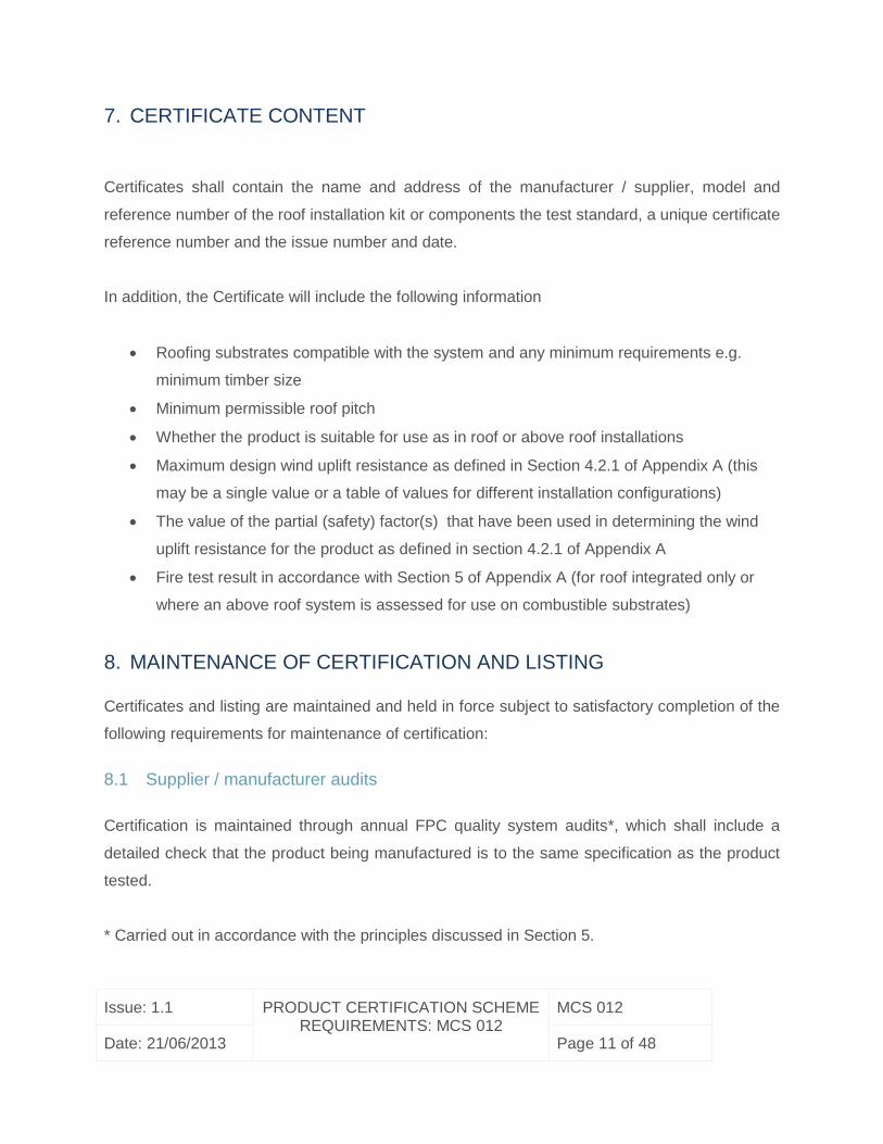
7. CERTIFICATE CONTENT
Certificates shall contain the name and address of the manufacturer / supplier, model and
reference number of the roof installation kit or components the test standard, a unique certificate
reference number and the issue number and date.
In addition, the Certificate will include the following information
Roofing substrates compatible with the system and any minimum requirements e.g.
minimum timber size
Minimum permissible roof pitch
Whether the product is suitable for use as in roof or above roof installations
Maximum design wind uplift resistance as defined in Section 4.2.1 of Appendix A (this
may be a single value or a table of values for different installation configurations)
The value of the partial (safety) factor(s) that have been used in determining the wind
uplift resistance for the product as defined in section 4.2.1 of Appendix A
Fire test result in accordance with Section 5 of Appendix A (for roof integrated only or
where an above roof system is assessed for use on combustible substrates)
8. MAINTENANCE OF CERTIFICATION AND LISTING
Certificates and listing are maintained and held in force subject to satisfactory completion of the
following requirements for maintenance of certification:
8.1 Supplier / manufacturer audits
Certification is maintained through annual FPC quality system audits*, which shall include a
detailed check that the product being manufactured is to the same specification as the product
tested.
* Carried out in accordance with the principles discussed in Section 5.

Issue: 1.1 PRODUCT CERTIFICATION SCHEME REQUIREMENTS: MCS 012
MCS 012
Date: 21/06/2013 Page 12 of 48
8.2 Product audits
Product audits will be conducted as follows:
8.2.1 review of the product technical data files including materials
8.2.2 review of end of line tests in accordance with the manufacturer's quality plan
8.2.3 repeat testing of elements from the product standard as appropriate to confirm that the
product continues to meet the requirements for certification and listing.
9. CERTIFICATION MARK AND LABELLING
All approved products listed under this scheme shall be traceable to identify that they have
(marked with a label to confirm that the product has) been tested and certificated in accordance
with the requirements of the test standard. See below for details.
The Supplier shall use (the) Certification Mark(s) (only) in accordance with the Certification
Bodies' instructions.
An example of the certification mark that can be used for this scheme is as follows:
Certificate Number MCS "XXX"
“Description of the Technology certificated”
Where ‘XXX’ is the certificate number and the logo of the certification body issuing the
certification would sit in the right hand box.
Companies may only use the mark while the certification is maintained

Issue: 1.1 PRODUCT CERTIFICATION SCHEME REQUIREMENTS: MCS 012
MCS 012
Date: 21/06/2013 Page 13 of 48

Issue: 1.1 PRODUCT CERTIFICATION SCHEME REQUIREMENTS: MCS 012
MCS 012
Date: 21/06/2013 Page 14 of 48
APPENDIX A
Pitched roof performance tests for solar thermal collectors &
PV modules
Issue: 1.1 PRODUCT CERTIFICATION SCHEME REQUIREMENTS: MCS 012
MCS 012
Date: 21/06/2013 Page 15 of 48
TABLE OF CONTENTS
1. INTRODUCTION .........................................................................................................17
2. SCOPE .......................................................................................................................17
3. INSTALLATION INSTRUCTIONS ...............................................................................18
4. RESISTANCE TO WIND UPLIFT ................................................................................19
4.1 Test method ........................................................................................... 19
4.2 Test criteria ............................................................................................ 20
4.2.1 Method.................................................................................................................20
4.2.2 Alternative methods .............................................................................................21
5. FIRE PERFORMANCE ...............................................................................................22
5.1 Roof integrated Systems ........................................................................ 22
5.2 Above-roof Systems ............................................................................... 23
6. WEATHERTIGHTNESS ..............................................................................................23
6.1 General .................................................................................................. 23
6.2 Test methods ......................................................................................... 25
6.2.1 Roof integrated systems ......................................................................................25
6.2.1.1 Test Procedure .................................................................................................25
6.2.1.2 Test criteria ......................................................................................................27
6.2.2 The performance of underlay penetrations. ..........................................................27
6.2.3 Above Roof Systems ...........................................................................................28
6.2.3.1 Weather-tightness of the penetrations through the outer surface ......................28
7. TEST REPORT ...........................................................................................................28
7.1 Product & System Details: ...................................................................... 29
7.2 Resistance to wind uplift ......................................................................... 30
7.3 Fire performance .................................................................................... 31
7.4 Weather tightness .................................................................................. 31
7.4.1 Roof integrated systems: .....................................................................................31
7.4.2 Underlay penetration (both roof integrated and above roof solar systems): ..........34
7.4.3 Above roof systems: ............................................................................................34
8. REFERENCES ............................................................................................................35
Issue: 1.1 PRODUCT CERTIFICATION SCHEME REQUIREMENTS: MCS 012
MCS 012
Date: 21/06/2013 Page 16 of 48
Appendix 1 ................................................................................................................................36
Test arrangement for carrying out tests to BS EN 14437 : 2004 ...................... 36
Appendix 2 ................................................................................................................................37
Annexes A & C of BS 476 -3 : 2004................................................................. 37
Appendix 3 ................................................................................................................................38
Test procedure for wind driven rain performance based upon prEN 15601 : 2006
38
1.1 Rain and Wind Driven Rain Effects .......................................................... 38
1.1.1 Test specimens .......................................................................................................38
1.1.2 Preparation of the test specimen .............................................................................39
1.1.3 Apparatus ................................................................................................................39
1.1.4 Pressure chamber ...................................................................................................39
1.1.5 Fan system .............................................................................................................40
1.1.6 Rain generating facility ............................................................................................41
1.1.7 Run-off water ..........................................................................................................41
1.1.8 Observation and measurement of leakage ..............................................................42
1.2 Test Procedure ........................................................................................ 42
Appendix 4 ................................................................................................................................44
An example of an underlay sealing ring in test for water-tightness .................. 44
Informative Annexes .................................................................................................................45
Annex 1.....................................................................................................................................45
Resistance to Wind Uplift ................................................................................ 45
REVISION OF MICROGENERATION CERTIFICATION SCHEME REQUIREMENTS .............47
AMENDMENTS ISSUES SINCE PUBLICATION ......................................................................48
Issue: 1.1 PRODUCT CERTIFICATION SCHEME REQUIREMENTS: MCS 012
MCS 012
Date: 21/06/2013 Page 17 of 48
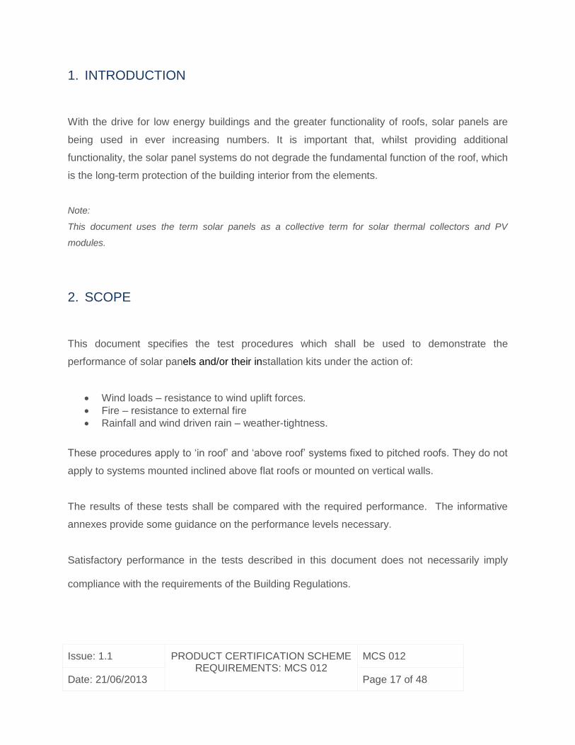
1. INTRODUCTION
With the drive for low energy buildings and the greater functionality of roofs, solar panels are
being used in ever increasing numbers. It is important that, whilst providing additional
functionality, the solar panel systems do not degrade the fundamental function of the roof, which
is the long-term protection of the building interior from the elements.
Note:
This document uses the term solar panels as a collective term for solar thermal collectors and PV
modules.
2. SCOPE
This document specifies the test procedures which shall be used to demonstrate the
performance of solar panels and/or their installation kits under the action of:
Wind loads – resistance to wind uplift forces.
Fire – resistance to external fire
Rainfall and wind driven rain – weather-tightness.
These procedures apply to ‘in roof’ and ‘above roof’ systems fixed to pitched roofs. They do not
apply to systems mounted inclined above flat roofs or mounted on vertical walls.
The results of these tests shall be compared with the required performance. The informative
annexes provide some guidance on the performance levels necessary.
Satisfactory performance in the tests described in this document does not necessarily imply
compliance with the requirements of the Building Regulations.

Issue: 1.1 PRODUCT CERTIFICATION SCHEME REQUIREMENTS: MCS 012
MCS 012
Date: 21/06/2013 Page 18 of 48
3. INSTALLATION INSTRUCTIONS
The product and installation kit must come with installation instructions. The installation
instructions must be followed when preparing the product and installation kit for test.

Issue: 1.1 PRODUCT CERTIFICATION SCHEME REQUIREMENTS: MCS 012
MCS 012
Date: 21/06/2013 Page 19 of 48
4. RESISTANCE TO WIND UPLIFT
4.1 Test method
In the absence of a test method specifically for assessing the uplift resistance of solar panels,
the test method shall follow the principles and, where appropriate, the details of BS EN 14437 :
2004 (Determination of the uplift resistance of installed clay or concrete tiles for roofing — Roof
system test method) (Reference 1). Note that a trial test, as specified in BS EN 14423 : 2004, is
not always necessary – this should be decided by the test house, depending on the system.
Appendix 1 shows a typical PV system under test.
The test shall determine the wind uplift resistance and the following details shall be followed:
I. Where the flashing or sealing kits provide any uplift resistance then these should be
included in the test.
II. The roof pitch shall be 45deg +/- 2 degrees.
III. A minimum of one solar panel should be tested (or two if shared components are
employed) and the test shall be repeated a minimum of three times with new fixings
each time.
IV. The uplift load shall be applied using a cable(s) or equivalent methods to provide uniform
loads. This\these may be fixed to the solar collector by drilling a hole(s) through the
collector or by using suction cup devices attached to the glass cover plate, as shown in
Appendix 1.
V. The detailed construction of the test rig in terms of the batten sizes, rafter spacing and
all fixings shall satisfy the minimum specification (worst case) of the
manufacturer/supplier of the solar panel and all materials shall be of a quality typical of
real construction. The minimum requirements of BS 5534 : 2003 shall also be satisfied.
VI. Where there is a choice of fixing positions, the most onerous (weakest) shall be tested.
VII. The test roof should include all components of typical construction, including the
adjacent tiles. Alternatively technical justification shall be provided as to why these are
omitted.

Issue: 1.1 PRODUCT CERTIFICATION SCHEME REQUIREMENTS: MCS 012
MCS 012
Date: 21/06/2013 Page 20 of 48
4.2 Test criteria
4.2.1 Method
The characteristic value(1) of the uplift resistance shall be determined (in kPa) from the
measured failure loads and reported in accordance with BS EN 14437 : 2004.
(1) The characteristic value has a prescribed probability of not being attained in a hypothetical
unlimited test series. This is defined in Annex D of BS EN 14437 : 2004 for a 5% confidence
limit.
For design purposes the characteristic uplift resistance load shall be divided by an appropriate
partial factor (safety factor) from the relevant Euro-Code:
For failure in steel or metal components – EN 1993-1-1 : 2005 Design of steel structures
— General rules and rules for buildings.
For failure in timber – EN 1995-1-1 : 2004 Design of timber structures — General rules
and rules for buildings.
The certificate shall declare the maximum design uplift resistance – the characteristic
resistance divided by the partial factor for the failure mode in the test.
In summary:
Ultimate Limit State (the system actually fails i.e. failure criteria a, b or c below):
For failure in a metal component the partial factor is 1.1
For pull out from a metal component (eg; self-tapping screw or rivet) the partial factor is
1.25
For failure in a timber component or pull out from a timber component the partial factor
for design against wind loads is 1.44(2)
(2) This value has taken into account the influence of load duration and other parameters in-line
with EN1995-1 Table 2.2 and clause 2.3.1.
Serviceability Limit State (no failure but the system is no longer fit for purpose i.e. failure
criteria d or e below).
The partial factor is 1.0

Issue: 1.1 PRODUCT CERTIFICATION SCHEME REQUIREMENTS: MCS 012
MCS 012
Date: 21/06/2013 Page 21 of 48
As written, the failure criteria specified in BS EN 14437 : 2004 are not appropriate to solar
systems and MCS012 failure criteria shall be taken as follows:
a) breakage of the mechanical fixing between the roofing element & the structure
b) pulling out or breakage of the connection of the mechanical fixing to the roof
c) breakage of covering elements
d) if the maximum displacement of any roofing element exposes the under-roof then the
maximum deflection shall be 75mm.
e) the remaining displacement of any roofing element after releasing the force to zero exceeds
5mm and degrades the weathertightness of the roof. (When the 5mm limit is achieved the test
should be continued until the applied load is at least 1.5 times the load measured at the 5mm
limit, or until ultimate failure occurs. This is to ensure that the design resistance derived does
not exceed the ultimate resistance divided by the appropriate partial factor).
Note:
1. Annex 1 gives guidance regarding the required uplift resistance for a given site
2. When assessing the adequacy of the system, partial factors must also be applied to the design
loads, increasing them in accordance with Tables A1.1 & A1.2 of EN 1990 : 2002. For the design
against wind uplift the partial factor for self-weight shall be 1.0 and for wind suction loads 1.5.
However, in normal use solar panels may be designated with a lower consequence of failure than
for the supporting building structure, in accordance with Table B1 of EN 1990 : 2002 + A1:2005
Consequence Class CC1. As a result the partial factor for design wind loads may be multiplied by
0.9 (Factor KFI for Reliability Class RC1 from Table B3 of EN 1990 : 2002 + A1 : 2005) giving a
net increase of 1.35 applied to the design wind suction loads.
4.2.2 Alternative methods
Where it can be demonstrated that alternative methods provide equivalent or conservative
(safe) values of the resistance to wind uplift then these may be used.
Depending upon the failure mode and the method of mounting other acceptable methods may
include:
i) DD CEN TS 15087 : 2005 “Determination of the uplift resistance of installed clay and concrete
interlocking tiles for roofing – Test method for mechanical fasteners.” (Reference 9)
Issue: 1.1 PRODUCT CERTIFICATION SCHEME REQUIREMENTS: MCS 012
MCS 012
Date: 21/06/2013 Page 22 of 48
Note:
This test method may be appropriate for some designs of roof integrated systems. It is not suitable for
above-roof systems.
ii) EN 12975-2 : 2006 Thermal solar systems and components — Solar Collectors — Test
methods, or BS EN 61215 : 2005 or EN 61646 : 2008 providing the mounting arrangement
complies with the requirements of clause 4.1 v) & vi) above.
iii) Validation by calculation alone
In some simple cases it may be possible to validate the system against wind loads by
calculation only. However, this is often not possible because, for instance: a) the failure modes
are not wholly predictable, b) tabulated fastener withdrawal loads from standards are often not
applicable due to the fastener diameter/timber thickness ratio.
5. FIRE PERFORMANCE
The test requirements are different for roof integrated and above roof systems.
5.1 Roof integrated Systems
Roof integrated systems shall be tested in accordance with BS 476-3 : 2004 (Reference 3) or
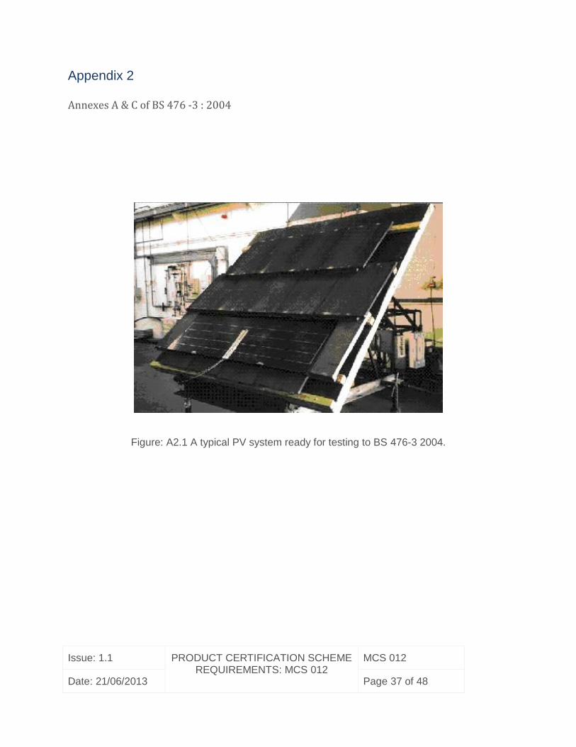
DD ENV 1187 : 2002 Test 4 (Reference 11), and the rating must be declared. Appendix 2
shows the test arrangement.
Note:
i) Applying this test to solar systems is not without its problems and guidance is provided in
Annex C (normative) of BS 476-3 : 2004.
ii) Past experience suggests that the flashings around and between the panels often pose the
greatest risk due to unprotected gaps.

Issue: 1.1 PRODUCT CERTIFICATION SCHEME REQUIREMENTS: MCS 012
MCS 012
Date: 21/06/2013 Page 23 of 48
iii) For large systems it may be necessary to test more than one section to ensure the most
vulnerable areas are all tested.
5.2 Above-roof Systems
If the solar system is only used on roofs whose outer covering is non-combustible, as defined in
the Building Regulations, then no external fire test is required, otherwise the solar system
together with the outer roof covering shall be tested in accordance with BS 476-3 : 2004 or DD
ENV 1187 : 2002 Test 4.
6. WEATHERTIGHTNESS
6.1 General
The presence of the solar panel system must not decrease the weather performance of the roof
covering or the roof structure.
The manufacturer/supplier shall declare which generic product classes their system can be
used with:
Profiled or flat single lapped tiles (profiled are recommended for test).
Plain tiles (double lapped product).
Double lapped slates (natural or synthetic).
Profiled metal sheets or standing seam roof coverings.
Any other generic roofing type.

Issue: 1.1 PRODUCT CERTIFICATION SCHEME REQUIREMENTS: MCS 012
MCS 012
Date: 21/06/2013 Page 24 of 48
Where a single flashing kit is specified for use with more than one generic class of roof
covering, then the class representing the worst case shall be tested. If the worst class is not
certain then other generic classes shall also be tested.
Note:
Based on past experience the biggest risks of water entry are as follows:
Roof integrated systems:
i) The risk of water entry over the flashing kit which is around, between and, in some
cases, under the panels. This water entry can be, for instance, at the interface with the roof
covering, at the interface with the panels, or through joints in the flashings.
ii) Water entry through the roof covering related to increased gapping of the roofing
elements due to the presence of the solar panel system, including its fixing system.
iii) Penetrations through the underlay can also pose a risk. Such penetrations must not
jeopardise the role of the underlay, as specified in BS 5534 : 2003 (Section 4.10) and should
therefore be sealed in an appropriate and durable manner, preferably with a purpose designed
product.
Above roof systems:
i) Water entry via the penetrations through the outer roof covering.
ii) Spray entry through any gaps in the outer-roof covering created by the mounting
arrangement.
iii) Penetrations through the underlay can also pose a risk. Such penetrations must not
jeopardise the role of the underlay, as specified in BS 5534 : 2003 (Section 4.10) and
should therefore be sealed in an appropriate and durable manner, preferably with a
purpose designed product.

Issue: 1.1 PRODUCT CERTIFICATION SCHEME REQUIREMENTS: MCS 012
MCS 012
Date: 21/06/2013 Page 25 of 48
6.2 Test methods
The test methods address the leakage mechanisms.
6.2.1 Roof integrated systems
6.2.1.1 Test Procedure
The principles of the draft European wind driven rain test for roofs (prEN 15601 : 2006) shall be
used to determine the wind driven rain performance of the roof integrated solar panel systems.
The test shall be carried out at the minimum pitch of the tile/solar panel combination.
prEN15601 : 2006 specifies 4 different wind-rain combinations (A – D), covering a range of
severe UK coastal conditions (referred to as N. European coastal in prEN 15601 : 2006). These
conditions are summarised in Appendix 3.
For solar panels, provided all unprotected gaps caused by the mounting and installation
arrangement are no greater than those pre-existing in the roof covering before the installation of
the solar panels then only Test D is mandatory; providing there is no reason to believe the
gapping will increase due to wind. Tests A – C are then optional.
Note:
Test D is the test with the largest rainfall rate (225mm / hour). Since the limit on the flashing is often the
water carrying capacity, this is a sensible compromise, addressing the highest risk leakage mechanism.
If only Test D is to be carried out then a simplified test facility may be used, which does not have the
pressure chamber, suction device, or fan system required in prEN 15601 : 2006.

Issue: 1.1 PRODUCT CERTIFICATION SCHEME REQUIREMENTS: MCS 012
MCS 012
Date: 21/06/2013 Page 26 of 48
If the installation of the system creates unprotected gaps larger than those pre-existing then, as
a minimum, wind-rain combinations B & D must be tested.
The test specimen shall be constructed in accordance with the manufacturer’s laying
specifications (complete with tiles or other outer roof covering elements) but without the roofing
underlay present, so that any water entry may be observed and collected. The tiles or roofing
elements used shall be well established in the market with known satisfactory field performance.
The test specimen shall be mounted in the test apparatus and subjected to the chosen wind-rain
combination. In the case of wind-rain combinations A, B & C, a uniform suction pressure is then
applied to the underside of the test specimen, in increasing steps (one step every 5 minutes)
until a leakage rate of 10g/m2/5min time step is observed. The amount of suction required to
bring about this level of leakage is the test result for that wind-rain combination and provides a
measure of the rain tightness of the system.
In the case of wind-rain combination D there is no applied suction, as this is simulating a zero
wind condition. The test specimen is subjected to the test D rainfall for 2 minutes and any water
entry is noted and weighed.
The quantity of water running onto the top of the solar panel (‘run-off water’) shall be adjusted to
simulate the worst case (widest panel and longest rafter length of roof). The minimum simulated
additional rafter length above the solar panel shall be 5m.
Note:
Due to the complexity and size of solar systems, it can be difficult to get a whole panel or panels onto the
test rig for test. It is often necessary to make up special samples which ensure the most vulnerable parts
of the solar array are tested. It is necessary to ensure that all joints and other vulnerable parts of the test
sample are representative of normal production. Alternatively, more than one configuration should be
tested in order to ensure that one of each joint and interface type are tested.

Issue: 1.1 PRODUCT CERTIFICATION SCHEME REQUIREMENTS: MCS 012
MCS 012
Date: 21/06/2013 Page 27 of 48
6.2.1.2 Test criteria
The performance of the surrounding roof covering elements which are unaffected by the
presence of the solar panels shall be taken as a benchmark against which to judge the
performance of the solar panels. To be acceptable the solar panel system shall have a level of
performance at least equal to that of the unaffected roofing elements, or equal to that of any
other roofing element of known acceptable performance. If necessary a reference test shall be
carried out with the test roof constructed wholly of roofing elements. The reference test must be
carried out at the same laboratory as the test on the solar panel system.
For wind-rain combinations A, B and C, the comparison shall be made on the basis of the level
of suction necessary to bring about a leakage rate of 10g/m2/5min time step.
For wind combination D the comparison shall be made on the basis of any water entry during
the 2 minute test period.
6.2.2 The performance of underlay penetrations.
The sealing arrangement for the underlay penetrations shall be tested for weather-tightness.
This shall be done with the underlay system fitted in place of the solar panel and tiles. The test
shall follow the same test procedure as the Test D of Section 6.2.1.1 but should use a rainfall
rate of 50mm/hr instead of 225mm/hr. In addition there should be no direct rainfall, only run-off
water applied at the top of the inclined roof rig, assuming a rafter length of 5m. The product
shall be deemed to have passed the test if there is no water leakage through the joint with the
underlay after 5 minutes.
Note: Appendix 4 shows an example of an underlay sealing device undergoing a test.
Issue: 1.1 PRODUCT CERTIFICATION SCHEME REQUIREMENTS: MCS 012
MCS 012
Date: 21/06/2013 Page 28 of 48
6.2.3 Above Roof Systems
Provided all unprotected gaps caused by the mounting and installation arrangement are no
greater than those pre-existing in the roof covering before the installation of the solar panels,
then only the weather-tightness of the outer surface penetrations and the underlay penetrations
need be tested.
The penetrations through the outer surface shall be tested in accordance with Section 6.2.3.1,
whilst the penetrations through the underlay shall be tested in accordance with Section 6.2.2.
If the installation of the system creates unprotected gaps lager than those pre-existing, then the
system, including the solar panels, shall be tested in accordance with Section 6.2.1.1 and no
separate test is required for the penetrations through the outer roof covering.
6.2.3.1 Weather-tightness of the penetrations through the outer surface
Carry out Test D (Section 6.2.1.1) on the outer roof covering, with one or more penetrations
installed but without the solar panel system in place. There should be no dripping from the
penetration into the batten space during the 2 minute test period.
For some designs of penetrations a simpler ‘impermeability test’ can be considered as
equivalent and sufficient. This simple test follows the principles of the water impermeability test
in BS EN 490 : 2011 or BS EN 491 : 2011 (European concrete tile standard and associated test
methods – References 7 & 8).
7. TEST REPORT
Issue: 1.1 PRODUCT CERTIFICATION SCHEME REQUIREMENTS: MCS 012
MCS 012
Date: 21/06/2013 Page 29 of 48
The test report shall include the following details:
7.1 Product & System Details:
Solar panel:
Manufacturer:
Model:
Dimensions:
o Specify roof integrated or above roof design:
Supplied by (company / person):
Date received:
Laying instructions – publication date/version/edition:
Flashing kit (where appropriate):
Manufacturer:
Model:
Supplied by (company / person):
Fitting instructions – publication date/version/edition:
Outer roof penetrations/fixings (where appropriate):
Manufacturer:
Model:
Supplied by (company / person):
Fitting instructions – publication date/version/edition:
Roof covering elements included in tests:
Manufacturer:
Model:

Issue: 1.1 PRODUCT CERTIFICATION SCHEME REQUIREMENTS: MCS 012
MCS 012
Date: 21/06/2013 Page 30 of 48
Performance parameters tested:
Yes / No Test dates
Resistance to wind uplift:
Fire performance:
Weather tightness:
7.2 Resistance to wind uplift
Specify all details of the system considered:
(All details influencing the uplift resistance are to be given, including all timber sizes,
fixings, roof covering elements and fixings of those.)
State method of assessment:
BS EN 14437 :
2004
DD CEN TS15087
: 2005
EN 12975-2 : 2006 or
EN 61215 : 2005 or EN
61646 : 2008
Calculation Other
State the results and conclusions including all failure modes found or considered. When an
appropriate EN standard or equivalent is used, the reporting shall be in accordance with that
standard.

Issue: 1.1 PRODUCT CERTIFICATION SCHEME REQUIREMENTS: MCS 012
MCS 012
Date: 21/06/2013 Page 31 of 48
7.3 Fire performance
Where required, report the results in accordance with BS 476-3 : 2004 or DD ENV 1187 : 2002
Test 4.
7.4 Weather tightness
7.4.1 Roof integrated systems:
State whether whole panels with flashing tested or sections:
(in the case of a section of a panel state the reason and the specific items tested)
Manufacturer’s declaration of generic product classes the system is suitable for:
Generic class Yes/No Minimum pitch specification
Profiled or flat single lapped tiles
Plain tiles
Double lapped slate (natural &
synthetic)
Profled metal sheets or standing seam
Any other generic class (state)
Roof covering elements used as a reference (manufacturer, model, pitch & headlap):

Issue: 1.1 PRODUCT CERTIFICATION SCHEME REQUIREMENTS: MCS 012
MCS 012
Date: 21/06/2013 Page 32 of 48

Issue: 1.1 PRODUCT CERTIFICATION SCHEME REQUIREMENTS: MCS 012
MCS 012
Date: 21/06/2013 Page 33 of 48
Gapping information:
Roof covering elements (without solar system):
Maximum unprotected gapping (mm to an accuracy of ±1.0mm):
Solar system:
Maximum unprotected gapping (mm to an accuracy of ±1.0mm):
Tests carried out & result:
Test Test pitch Test Result for
system
Test Result
for
Reference
product
A Applied suction (Pa) at
leakage rate at10g/m2/5min:
B Applied suction (Pa) at
leakage rate (Pa) at
10g/m2/5min:
C Applied suction (Pa) at
leakage rate (Pa) at
10g/m2/5min:
D Leakage observed after 2 min:
Additional Rafter length simulated (m):
Panel width simulated if greater than physical width of panel tested (m):
Performance assessment compared with test criteria:

Issue: 1.1 PRODUCT CERTIFICATION SCHEME REQUIREMENTS: MCS 012
MCS 012
Date: 21/06/2013 Page 34 of 48
7.4.2 Underlay penetration (both roof integrated and above roof solar systems):
Product specification (underlay seal):
Manufacturer of product used:
Model:
Supplied by (company/person):
Underlay used in the test (manufacturer/product name):
Test result:
7.4.3 Above roof systems:
If the whole system is tested then report in accordance with the roof integrated system.
If only the outer roof penetrations are tested then report as follows:
Gapping information:
Roof covering elements ( without solar system):
Maximum unprotected gapping (mm to an accuracy of ±1.0mm):
Solar system (roof covering elements with outer roof penetrations fitted):
Maximum unprotected gapping (mm to an accuracy of ±1.0mm):
Test carried out:
Test result:
Performance assessment compared with criteria:

Issue: 1.1 PRODUCT CERTIFICATION SCHEME REQUIREMENTS: MCS 012
MCS 012
Date: 21/06/2013 Page 35 of 48
8. REFERENCES
BS EN 14437 : 2004 Determination of the uplift resistance of installed concrete or clay
tiles for roofing-roofing system test method
BS 5534 : 2003 Code of practice for slating and tiling (including shingles)
BS 476-3 : 2004 Fire tests on building materials and structures — Classification and
method of test for external fire exposure to roofs
BS EN 13501-1 : 2007 Fire classification of construction products and building elements
— Classification using test data from reaction to fire tests
BS EN 13501-5 : 2005 Fire classification of construction products and building elements
— Classification using data from external fire exposure to roofs tests
prEN 15601 : 2006 Hygrothermal performance of buildings — Resistance to wind-driven
rain of roof coverings with discontinuously laid small elements — Test Method
BS EN 490 : 2011 Concrete roofing tiles and fittings for roof covering and wall cladding
— Product specifications
BS EN 491: 2011 Concrete roofing tiles and fittings for roof covering and wall cladding
— Test methods
DD CEN TS15087 : 2005 Determination of the uplift resistance of installed clay and
concrete interlocking tiles for roofing — Test method for mechanical fasteners
EN 12975-2 : 2006 Thermal solar systems and components — Solar collectors — Test
methods
DD ENV 1187 : 2002 Test methods for external fire exposure of roofs.
BS 6399-2 : 1997 Loading for buildings. Code of practice for wind loads.
EN 1991-1-4 : 2005 Eurocode 1. Actions on Structures. General actions. Wind loads.
BRE Digest 489 Wind loads on roof-based photovoltaic systems.

Issue: 1.1 PRODUCT CERTIFICATION SCHEME REQUIREMENTS: MCS 012
MCS 012
Date: 21/06/2013 Page 36 of 48
Appendix 1
Test arrangement for carrying out tests to BS EN 14437 : 2004
Figure A1.2 Typical PV System undergoing a wind uplift test according to the principles of BS
EN 14437 : 2004
Issue: 1.1 PRODUCT CERTIFICATION SCHEME REQUIREMENTS: MCS 012
MCS 012
Date: 21/06/2013 Page 37 of 48
Appendix 2
Annexes A & C of BS 476 -3 : 2004
Figure: A2.1 A typical PV system ready for testing to BS 476-3 2004.

Issue: 1.1 PRODUCT CERTIFICATION SCHEME REQUIREMENTS: MCS 012
MCS 012
Date: 21/06/2013 Page 38 of 48
Appendix 3
Test procedure for wind driven rain performance based upon prEN 15601 : 2006
Figure A3.1 A PV system laid ready for wind driven rain tests
1.1 Rain and Wind Driven Rain Effects
A solar energy specimen is fitted into the wind-driven rain apparatus, the external
surface of the specimen is exposed to wind and continuously sprayed with water and
run-off water is continuously applied at the top of the specimen. At the same time an
air pressure difference between the upper and lower sides of the test specimen is
increased or decreased in specific steps. Water leakage through the test specimen
which may occur at certain air pressure differences is observed and measured.
1.1.1 Test specimens
Samples for the test specimen shall comply with the product specifications and be
representative of normal production.
The dimensions of the test specimen shall be as large as necessary to be
representative of the intended use. The test specimen shall include at least one of
every type of joint between the solar energy specimen and the surrounding roof
surface (where appropriate). In some cases with large solar energy specimens, it
Issue: 1.1 PRODUCT CERTIFICATION SCHEME REQUIREMENTS: MCS 012
MCS 012
Date: 21/06/2013 Page 39 of 48
might not be possible to test all of the joints simultaneously in the same test. In such
cases the testing shall be repeated to ensure that each joint is fully tested. The
minimum number of tests shall be one. The test specimen shall include all
representative joints, where this is not possible then additional tests will be required
to test each joint separately.
1.1.2 Preparation of the test specimen
Construct the test specimen according to the manufacturer/supplier’s specification
representative of its intended use (such as roof pitch, fixing systems, etc). The test
specimen may be built in a surrounding frame to facilitate transport and fitting to the
opening of the driving rain test apparatus. The joint between test specimen and
surrounding frame shall be sealed to prevent water leakage during the test, without
disturbance to the normal occurring gaps in the specimen. If a frame is used, it shall
be able to resist the pressures applied during the test without deflecting to an extent
to influence the test results. The surround shall be prepared and installed so that any
water penetration through the test specimen is readily detectable.
1.1.3 Apparatus
The test apparatus shall consist of:
a pressure chamber sealed to the underside of the test specimen and
connected to a pressure generator, as specified in 1.1.4 below;
a fan system to create wind on the outside of the test specimen, as specified
in 1.1.5 below;
a facility for generating rain, as specified in 1.1.6 below;
provisions for creating run-off water as specified in 1.1.7 below; and
a facility for observation and measurement of leakage as specified in 1.1.8
below;
NOTE. Apparatus of different design may produce different wind driven rain test
results, but can produce consistent comparisons of performance between different
roof covering products.
1.1.4 Pressure chamber

Issue: 1.1 PRODUCT CERTIFICATION SCHEME REQUIREMENTS: MCS 012
MCS 012
Date: 21/06/2013 Page 40 of 48
The pressure generator connected to the pressure chamber shall be capable of
creating a stable negative or positive pressure difference, maintained for 5 minutes
±10s, across the test specimen. The pressure difference shall be measured to a
maximum inaccuracy of 1% or 2.5 Pa, whichever is greater. The volume of the
pressure chamber shall be sufficient to ensure uniform pressure conditions. A water
collector shall be provided connected to the pressure chamber capable of recording
the amount of leakage water during any pressure step in the test, to a maximum
inaccuracy of 2 % or 1 g, whichever is greater. The surfaces of the pressure chamber
shall allow leakage water to flow freely into the water collector.
1.1.5 Fan system
The fan system shall be capable of generating wind directed parallel to the
longitudinal axis of the test specimen. The wind flow may be horizontal or parallel to
the surface of the test specimen. The spatial variation of the wind speed shall be not
more than 10 % over the test specimen. Calibrate the fan system for spatial variation
of the wind speed, by taking measurements at not less than 9 positions uniformly
distributed at a height of 200 + 10 mm over a flat boarded area which replaces the
test specimen, at the relevant roof pitch. The calibration wind speed shall be 10 + 0.5
m/s at the centre of the test specimen.
The wind speed (Vi) shall be measured to a maximum inaccuracy of 0.5 m/s.
The turbulence intensity (t) in the oncoming wind shall be less than 10 %.
NOTE: The turbulence intensity t (%) is expressed as t = 100u/U, where u and U are
the RMS and mean wind speeds respectively, measured over a duration of not less
than 5 minutes for this purpose.
RMS (root mean square) wind speed 1
)(1
2
n
U
u
n
iiV
Mean wind speed n
U
n
iiV
1
Where Vi is the individual wind speed;

Issue: 1.1 PRODUCT CERTIFICATION SCHEME REQUIREMENTS: MCS 012
MCS 012
Date: 21/06/2013 Page 41 of 48
n is the number of measurements
1.1.6 Rain generating facility
The facility shall be capable of supplying a stable rain rate. The spatial variation shall
be not more than ±35% over the area of the test specimen during a time period of 5
min±10s. During the same time period of 5 min ±10s the rainfall rate shall vary by not
more than ±2%. The rain droplet size shall be representative of natural rain,
predominantly in the range of 0.6mm to 2.5mm diameter.
The variation of rainfall over the specimen can be measured using rain collectors with
an area of 0.10 m2 to 0.20 m2 in area and arranged so that they do not collect any
run-off water during calibration. To calibrate the rain falling directly on the test
specimen, replace the test specimen with a flat board which incorporates the rain
collectors in its upper surface. The calibration should be carried out for each wind-
rain combination used. The rain shall be measured to a maximum inaccuracy of 3%
or 0.2 mm/h, whichever is larger.
NOTE 1. Water droplets introduced into a high velocity air stream tend to break up
over distance. Accordingly it is recommended that the droplets are introduced far
enough above the test specimen for this process to be completed and for the
droplets to achieve the required velocity prior to impact with the test specimen.
NOTE 2: A variation of ±35% in wind driven rain distribution when combined with run-
off water (see 8.3.3.4) results in a combined variation of not more than 10%.
1.1.7 Run-off water
Run-off water shall be evenly distributed across the top of the test specimen. The
run-off rate shall not vary by more than 10 % over the width of the test specimen. The
quantity of run-off water shall be measured to a maximum inaccuracy of 3%.
The run-off rate Rro shall be calculated by the formula:
Rro = Rtest W L / 60
where:
Rro is the run-off rate, in l/m;

Issue: 1.1 PRODUCT CERTIFICATION SCHEME REQUIREMENTS: MCS 012
MCS 012
Date: 21/06/2013 Page 42 of 48
Rtest is the rainfall on the roof surface in mm/h;
W is the effective width of the test specimen, in m;
L is the simulated additional rafter length above the test specimen, in m.
Unless otherwise specified, L shall be not less than 5 m.
1.1.8 Observation and measurement of leakage
The pressure chamber shall be provided with:
a) a transparent under-surface for clear visual observation of the nature and position
of leakages which may appear on the underside of the test specimen during the test;
b) an apparatus to continuously collect and measure the amount (by weight or by
volume) of leakage water which may fall from the test specimen into the pressure
chamber during the test.
To minimize surface tension, absorption and retention of water on the internal
surfaces of the pressure chamber, the surfaces shall be smooth, non-absorbent and
inclined at a vertical angle of not less than 15° from the horizontal towards the lower
collecting apparatus during testing.
1.2 Test Procedure
Carry out the test in an environment with a temperature of between 5°C to 35°C with
the test specimen installed in the apparatus at the specified roof pitch. Seal the
edges of the test specimen as appropriate to prevent leakage of water or air into or
out of the pressure chamber. The test specimen shall be surface dry before each
test.
Select and continuously apply the relevant wind speed, rain-fall rate, and amount of
run-off water for each wind-rain combination as specified in Table 6.1
Table 6.1 Wind-rain conditions for Northern Europe Coastal climate zone
Climate zone Wind-rain
combination
Test conditions +

Issue: 1.1 PRODUCT CERTIFICATION SCHEME REQUIREMENTS: MCS 012
MCS 012
Date: 21/06/2013 Page 43 of 48
Approach Wind
speed
Vr (m/s)
Rainfall on horizontal
Rh (mm/h)
Northern
Europe Coastal
A 5 110
B 13 60
C 25 6
D 0 225
+ Note: See prEN 15601 : 2006 for the methodology to determine the wind and rain
over the roof surface, as a function of roof pitch.
In summary these combinations are:
Combination A: Low wind speed with severe rainfall rate;
Combination B: High wind speed with high rainfall rate;
Combination C: Severe wind speed with low rainfall rate;
Combination D: Maximum rainfall rate with no wind (deluge).
In the wind-rain combinations A, B and C, measure initially the pressure difference
with the pressure box closed and adopt this pressure difference as the reference
zero for subsequent pressure changes during the test. Then reduce the pressure in
the box in steps of not less than 5 Pa and maintain each pressure step for 5 minutes
+ 10 seconds, until leakage is observed. Measure the amount of leakage water at
each pressure step, or continuously, up to the reference leakage rate.
In the deluge test, combination D, apply the rainfall and run-off without wind and with
the pressure box open to the atmosphere, for 2 minutes + 10 seconds. Observe any
leakage and measure the amount of leakage water.
NOTE 1: The sub-test may be continued at greater pressure differences to observe
more leakage.
NOTE 2: Fine spray may leak through the joints in certain types of solar energy
specimens. Its occurrence should be recorded. Such fine spray may or may not be
regarded as leakage depending on the leakage criterion adopted.
Issue: 1.1 PRODUCT CERTIFICATION SCHEME REQUIREMENTS: MCS 012
MCS 012
Date: 21/06/2013 Page 44 of 48
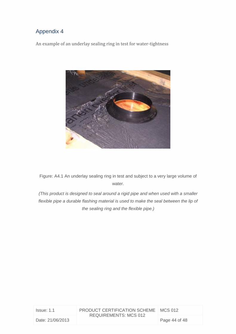
Appendix 4
An example of an underlay sealing ring in test for water-tightness
Figure: A4.1 An underlay sealing ring in test and subject to a very large volume of
water.
(This product is designed to seal around a rigid pipe and when used with a smaller
flexible pipe a durable flashing material is used to make the seal between the lip of
the sealing ring and the flexible pipe.)

Issue: 1.1 PRODUCT CERTIFICATION SCHEME REQUIREMENTS: MCS 012
MCS 012
Date: 21/06/2013 Page 45 of 48
Informative Annexes
Annex 1
Resistance to Wind Uplift
System Requirements
2 System requirement Design Loads
The method of mechanical fixing of the collectors to the roof, and the fixing
components, must be adequate to resist the design loads derived from the relevant
parts of BS 6399 or EN 1991-1. These design loads relate to dead and imposed
loads, wind loads and other environmental loads such as snow loads. The fixings
shall be capable of resisting these loads, preferably without maintenance for their full
service lifetime.
The test method described is intended to assess the adequacy of the fixings against
wind uplift loads only.
2.2 Design wind speed
The design wind speed (and wind dynamic pressure) is used to calculate the design
wind load and may either be:
a) determined using BS 6399-2 : 1997 or EN 1991-1-4 : 2005 for a particular site
in question.
Or
b) taken as a sensible upper estimate which will cover all buildings up to three
storeys in height anywhere in the UK, provided that topographical features
(eg; hills and valleys) are not significant. A 1 second gust wind speed with an
annual probability of 0.02 and equal to 58ms-1 is suggested.
Where topographical features are significant the design wind speed must be checked
using BS 6399-2 : 1997 or EN 1991-1-4 : 2005.
2.3 Design wind loads

Issue: 1.1 PRODUCT CERTIFICATION SCHEME REQUIREMENTS: MCS 012
MCS 012
Date: 21/06/2013 Page 46 of 48
BRE Digest 489 “Wind loads on roof-based photovoltaic systems” also provides
additional guidance on deriving the wind loads on the solar panels and their fixings.
The design wind load shall then be derived as follows:
I. For roof integrated designs
II. For air permeable roof integrated systems, which replace roof tiles, BS 5534 :
20031 may be used to derive the design wind loads acting on the collectors
and fixings. BS 5534 : 2003 takes account of the reduction in the wind loads
due to the air permeability of the installed panels and surrounding roof tiles.
BS 5534 : 2003 also presents the principles and a test methodology for
measuring the level of air permeability.
III. For non air permeable systems use BS 6399-2 : 1997 or BS EN 1991-1-4 :
2005 to derive the design wind loads.
IV. For on-roof systems, the wind loads shall be assessed using BS 6399-2 :
1997 or EN 1991-1-4 : 2005.
Additional guidance is given in BRE Digest 489
2.4 Other requirements not tested:
In addition the collector fixings have to:
possess sufficient shear strength to resist gravitational sliding of the panel
due to its weight and imposed snow loads.
withstand other effects such as fatigue loading due to variation in the wind
forces and differential thermal movements,
resist abrasion against roof tiles and other nearby materials,
be resistant to corrosion due to rain and accumulated debris.
These properties are not tested in the test method proposed.

Issue: 1.1 PRODUCT CERTIFICATION SCHEME REQUIREMENTS: MCS 012
MCS 012
Date: 21/06/2013 Page 47 of 48
REVISION OF MICROGENERATION CERTIFICATION SCHEME
REQUIREMENTS
REVISION OF MCS REQUIREMENTS
MCS scheme requirements will be revised by issue of revised editions or
amendments. Details will be posted on our website at
www.microgenerationcertification.org
Technical or other changes which affect the requirements for the approval or
certification of the product or service will result in a new issue. Minor or administrative
changes (e.g. corrections of spelling and typographical errors, changes to address
and copyright details, the addition of notes for clarification etc.) may be made as
amendments.
The issue number will be given in decimal format with the integer part giving the
issue number and the fractional part giving the number of amendments (e.g. Issue
3.2 indicates that the document is at Issue 3 with 2 amendments).
Users of this standard should ensure that they possess the latest issue and all
amendments.

Issue: 1.1 PRODUCT CERTIFICATION SCHEME REQUIREMENTS: MCS 012
MCS 012
Date: 21/06/2013 Page 48 of 48
AMENDMENTS ISSUES SINCE PUBLICATION
Document Number: Amendment Details: Date:
Issue 1.0 First Issue 16/03/2012
Issue 1.1 Update to date of
implementation from
16/09/2012 to 31/03/2013
21/06/2013
Top Related