


Languages
Pages
Legal


www.siemens.com
Published by and copyright © 2007:
Siemens AGPower GenerationFreyeslebenstrasse 191058 Erlangen, Germany
Oil & Gas andIndustrial ApplicationsWolfgang-Reuter-Platz47053 Duisburg, Germany
Siemens Industrial Turbomachinery, Inc.10730 Telge Road; HoustonTexas 77095, USA
www.siemens.com/agkkk
Order No. A96001-G90-B157-X-4A00Printed in Germany1387 WS 09072.5
All rights reserved.Subject to change without prior notice.Printed on Paper treated with chlorine-free bleach
Trademarks mentioned in this document arethe property of Siemens AG, its affilates, or theirrespective owners.
The information in this document contains general descriptions of the technical options available, whichmay not apply in all cases. The required technical options should therefore be specified in the contract.
Power GenerationPower Generation Oil & Gas and Industrial Applications
Pre-Designed Steam TurbinesMechanical drives and turbogenerators from 45 kW up to 10 MW

Experience You Can Trust
Pre-designed Steam Turbines: System Solutions
Do you require process heat in the form of steam for your manufacturing operation? Or would you like to tap the energy potential of available waste heat flows? For such requirements, we can provide the following:
n Turbine components matched to your specific needs and expectations
n Many years of experience in advising customers and implementing complete turbine installations, e.g., for co-generation, waste disposal or waste heat utilization applications
Your benefit: Proven and cost-efficient turbine solutions that will reduce your electricity bill dramatically while enabling you to obtain process steam.
The high quality of our turbine technology, and the trust placed in us by our satisfied clientele, have been demonstrated in a diverse range of applications.
We are committed to providing our customers with comprehensive advice and support in all project phases.
The following examples from our services portfolio attest to this ambition:
n Advice to match your requirements on machine design and possibilities for integrating our steam turbines into your application environment
n Determination of space needs before the start of fabrication
n Installation and commissioning carried out exclusively by experienced specialists
n Personnel training in turbine operation and maintenance
n Storage and shipping logistics geared to ensure rapid availability and fast spare part supplies
n Assistance in the form of economically priced status analyses throughout the equipment's
service life
Complete turbine installations – the easy way to superior cost efficiency
At your request, we can supply your steam turbine with all requisite ancillary equipment such as
n Transmission(s)
n Driven machinery (pump, compressor, generator)
n Condenser
n Monitoring and control systems
Having determined the right turbine size on the basis of your requirements, we can design and build the entire turbine installation right down to its handover, ready for service. All equipment characteristics will conform to DIN 4312 and meet key specifications of API 611/612.
We can also take care of issues such as a torsion analysis of the overall system, foundation ratings, and support with the integration of turbine controllers into an overall process management system
Industrial applications served by SiemensPre-designed Steam Turbinesfrom 45 kW up to 10 MW
2 3
Examples
Waste disposal
BiomassCo-generation
Gas expansion
Waste heat utilization
Mechanical power supply
ORC / Geothermics
Chemicals n n n n n
Petrochemicals /Refinery n n n n
Power supply n n n n n n
Waste disposal n
Metallurgy / Steel n n n n
Wood processing n n
Papermaking n n
IPP / Contracting n n n n n n
Equipment fabrication n n n n n n n
Driven machines n
Sugar industry n n
Palm oil industry n n n n
Textile industry n n
Foodstuffs processing n n
Marine / Offshore n
Gas industry n n
Steam turbine AFA 4 G5a as a gas expansion turbine in a German electricity supplier’s plant
Tandem turbogenerator delivering an electrical output of 4,000 kW in a co-generation facility

Arguments in Favour of our Steam Turbines
* Actual savings may vary depending on specific equipment characteristics.
n Low investment cost
n Optimized price/performance ratio
n Highest availability and minimal maintenance needs thanks to straightforward, time-tested design
n Very good part-load performance and broad load range due to nozzle group control
n Fast start-up capability from cold to fully operable state
n High degree of automation
n Outstanding user friendliness and ease of operation
n Low space requirement
n Minimum foundation needs
n Service life in excess of 25 years
n Fast, economically priced siemens-service
Steam turbine TWIN-AFA 66 turbogenerator in a co-generation plant delivering an electrical output of 3.7 MW
EUR 100,000 p.a.*through steam expansion
E.g. Food processing operation
Use of reducer stations to expand steam from the medium-pressure saturated state to 3-bar and 6-bar mains system level.
Our solution with turbogenerator set
Turbogenerators were arranged in paral-lel with the reducer stations. Expanding steam in these turbines produces an additional 500 kW of electrical power by co-generation.
EUR 960,000 p.a.*through power generation
E.g. Wood processing plant
Generation of process steam for impreg-nation, heating and drying - with supply of power into the public grid.
Additional gains with two turbogenerators
Two turbogenerators delivering 2.4 MW were installed, both supplying power into the public grid. Thanks to automati-cally actuated nozzle group valves, these units achieve high efficiencies even in part-load operation.
EUR 450,000 p.a.*through waste heat utilization
E.g. Glassmaking
Large amounts of high-temperature waste heat are available from the heated glass tank
Combination solution with waste heat boiler and a Siemens steam turbine
A waste heat boiler supplies high-pres-sure steam to a 1.6-MW turbine. At 8,000 operating hours per year, elec- tricity costs are reduced by EUR 1.0 mil-lion!The costs of this combination solution were recovered within 2 years.
4 5
Siemens Pre-designed Steam Turbines Technology Realizes Savings Potentials:

Siemens Pre-designed Steam Turbine Technology
Turbine shaft and impeller
The turbine shaft with its impeller consists of one integral forging. Each of these components is subjected to 100% testing using ultrasound and magnetic particle methods to demonstrate its freedom from flaws. As a general rule, the turbine shaft and impeller operate rotodynamically between the first and second natural bending frequency. The unit runs very smoothly thanks to its dynamic self-centering action in this range.The rotor can be mounted in small-diameter bearings so that lower peripheral speeds benefit the turbine‘s service life.
Thanks to our unrivalled technological expertise, our steam turbines are noted for an array of outstanding features:
nCustom turbine design based on modular flexibilitynHigh energy efficiency through innovative multi- stage technology, high volume flows and small enthalphy differentialsnBroad output rangenSimple and rugged, long-life design
Operating principle of Siemens Pre-designed steam turbines
The turbines operate on the impulse principle. The incoming steam is expanded in the nozzles, resulting in a conversion of thermal energy into kinetic energy. The latter is in turn transformed into mechanical energy as the steam flow is deflected by the impeller blades.From the impeller, energy is passed to the driven machine or generator via a gear transmission unit and coupling.
Quick start capability
The special configuration of the runner bearings permits an extremely fast start-up from cold to full operating r.p.m. As a result, our turbines are suitable for both continuous service and frequent start-up/shutdown cycles. The start-up time is limited by the mass moment of inertia of co-rotating parts and/or by the boiler‘s operating characteristics. A high degree of operating safety and ease of maintenance reduce operating costs substantially.
6 7
Characteristic data and ranges of our turbines: Power range: 45 kW up to 10 MW Live steam pressure: 3 - 131 bar abs.Live steam temperature (dry, saturated): up to 530 °C Outlet steam pressure: 0.08 to 29 bar abs. Speed: 500 - 23000 r.p.m.
Power generation through steam expansion
Operation of driven machinery (e.g., pumps, compressors)
Power generation through gas expansion
Power generation through expansion of organic fluids
Product Range of Siemens Pre-designed Steam Turbines
BF Page 8
AF Page 9
CFA Page 10
AFA Page 10
AFR Page 11
CFR Page 11
TWIN Page 12
Tandem Page 12
Gas expansion Page 14
ECM Page 15
EPM Page 16
ORC Page 17
Output in kW 250 500 750 1000 2000 3000 4000 5000 10000

AF
n Frequent start-up and shutdown
n Quick-start capability
n Straightforward, low-maintenance design
n Horizontal installation
n Single-ring turbine rotor
n Axial through-flow
n Integral transmission for optimum load matching
9
BF turbines are single-stage, direct drive, back-pressure steam turbines in which the flow passes axially through the blading.The impeller, nozzle system and shaft gland seal are easy to reach.Similarly, all transmission components are readily accessible for maintenance.
This BF series steam turbines come with an all-hydraulic speed governor as standard. A mechanical trip device protects the turbine against overspeeds.
All pressure-loaded parts are extensively tested, and each turbine is subjected to a trial run before delivery.
BF turbines are typically used as a stand-by unit, e.g., for feedwater supply in power stations.
Siemens Pre-designed Steam Turbines: Our Series
BF – standby turbine with quick-start capability for up to 300 kWBF
n Frequent start-up and shutdown
n Quick-start capability
n Straightforward, low-maintenance design
n Horizontal installation
n Vertical installation is supported by Type 3.5 units
n Single-ring turbine rotor
n Axial through-flow
n Direct drive or equipped with transmission
8
AF – standby turbine with quick-start capability for up to 750 kW
Design size AF 3,5 Gs AF 4 Gs
Output [kW] 300 750
Speed [r.p.m.] 11000 10500
Live steam pressure [bar abs.] 101 101
Live steam temperature [°C] 500 500
Outlet steam pressure [bar abs.] 1-17 1-17
All data represent characteristic (maximum) values
Steam turbine AF 4 Gs driving a pump
Typical space requirement: 1.2 x 1.5 x 1.3 m (L x W x H)
AF turbines are single-stage back-pressure steam turbines in which the flow passes axially through the blading. The impeller, nozzle system and shaft gland seal are easy to reach. Similarly, all trans- mission components are readily accessible for maintenance.
This AF 4 steam turbines come with a torsion bar speed governor as standard. Other governor sys-tems can also be connected. A bolt-type trip device protects the turbine against overspeeds.
All pressure-loaded parts are extensively tested, and each turbine is subjected to a trial run before delivery.
AF turbines are used e.g. as a power source for pumps or fans.
Design size BF 3.5 BF 4/80 BF 4/125
Output [kW] 45 250 300
Speed [r.p.m.] 4500 4500 4500
Live steam pressure [bar abs.] 101 46 26
Live steam temperature [°C] 500 500 430
Outlet steam pressure [bar abs.] 1-8 1-11 1-11
All data represent characteristic (maximum) values
Steam turbine BF 4/80 driving a pump in a biomass heating station
Typical space requirement: 1.0 x 1.0 x 1.3 m (L x W x H)

AFR, CFR
Siemens Pre-designed Steam Turbines: Our Series
AFA, CFACFA – the solution for high-pressuresteam expansion applications
10
The optimum solution for back-pressure turbines up to 6 MW
Our AFR and CFR series combine all design features and advantages of the AFA and CFA lines.
11
Design size AFR 3 CFR 3 CFR 5
Output [kW] 1500 2500 6000
Speed [r.p.m.] 24900 24900 16000
Live steam pressure [bar abs.] 65 65 65
Live steam temperature [°C] 480 480 480
Outlet steam pressure [bar abs.] 1-17 1-17 1-11
All data represent characteristic (maximum) values
n Radial Curtis rotor (CFR) or radial impulse wheel (AFR), both milled
nDirect-drive type or with integral single-stage spur gear unit
n Compact, space-saving design
n High mechanical efficiency due to low number of bearings
n Quick start without turbine preheating
n Automatic nozzle group control
Steam turbine CFR 5 G5a driving a generator in a wood processing plant.
Typical space requirement: 3.4 x 3.0 x 2.5 m (L x W x H)
Design size AFA 3.5 AFA 4 AFA 6 CFA 4
Output [kW] 600 2200 6000 1600
Speed [r.p.m.] 13600 18000 11400 10500
Live steam pressure [bar abs.] 101 131 41 41
Live steam temperature [°C] 500 530 450 450
Outlet steam pressure [bar abs.] 1-17 0,08-25 0,08-11 1-17
All data represent characteristic (maximum) values
n Curtis rotor (CFA) or axial wheel (AFA) made from solid material
n Direct-drive type or with integral single-stage spur gear unit
n Compact design
n High mechanical efficiency due to – Low number of bearing – Optimized runner diameter – Fitted blade height
n Automatic nozzle group control
n Quick start without turbine preheating
n Suitable for driving mechanical equipment or generators
AFA and CFA series turbines stand out by their rug-ged design and renowned reliability even under the most severe operating conditions.
AFA and CFA machines are ideal for saturated steam service. Their suitability for use as condensation or back-pressure turbines in combination with diverse transmission types opens up a broad application range.
Steam turbine CFR 3.5 G3a driving a pump set in a wood processing
plant in Argentina (application: waste heat utilization)
Typical space requirement: 2.7 x 2.2 x 2.1 m
(L x W x H)

TANDEM
13
This turbine concept permits a quick, low-cost and space-saving expansion of each unit. Tandem is the two-in-one solution!
In this machine configuration, output is increased by simply adding a second turbine. The genera-tor has two shaft ends and is placed between the low-pressure and high-pressure turbines. Electrical output can thus be boosted to as much as 10 MW.
An additional benefit of this tandem combination is that a controlled extraction feature, as required in co-generation heating plants, can be provided between the low-pressure and high-pressure units without additional cost.
At the customer‘s request we will design for a subsequent expansion already in the project phase even if only one turbine-generator set is initially installed.
n Reduction of high thermal gradients with good efficiency
n Pressure controlled supply for up to three steam systems
n Machines can be optionally supplied with an individual de-coupling capability for a flexible response to the customer‘s specific operating needs
n High flexibility through combination of individual steam turbine series
Tandem system comprising one TWIN-AFA 66 and one AFA 6 G6a in a biomass heating plant
Typical space requirement: 9.0 x 4.0 x 3.8 m (L x W x H)
Configuration example:
HP
LP
LP
Live steam40 bar abs. / 250°CF = 85 t/h
Live steam per ND turbine:5.5 bar abs. / 155°CF = 30 t/h
10300 KWe
Output steam 0.3 bar abs.
Output steam 0.3 bar abs.Process steam
extraction25 t/h
Siemens Pre-designed Steam Turbines: Our Variants
TWIN Multi-stage version for enhanced flexibility
12
HP
LP
Configuration example:
Live steam 27 bar abs. / 475°C
Controlled extraction (optional)
Condensation, extraction orback-pressure system, 0.1 bar abs.
2500 kWe
2 bar a / 228°C
The universal combination for superior output
Our multi-stage TWIN versions are noted for their particular cost efficiency and high performance. Proven turbine technology is enhanced by add-ing a second steam section. Thanks to the integral transmission, the compact design of each machine is preserved.
TWIN versions allow you to reduce high heat gradients while providing a controlled extraction capability. It is also possible to run the two turbines on different steam supplies.
The versatility of our turbine range can be further increased through a combination of tandem and TWIN versions. Such turbine configurations provide a pressure-controlled supply for up to three steam systems.
Steam turbine TWIN-CFR 55 driving the power generating system of a sugar mill (approx. 3.7 MW)
Typical space requirement: 3.6 x 2.4 x 2.8 m (L x W x H)
EPM
15
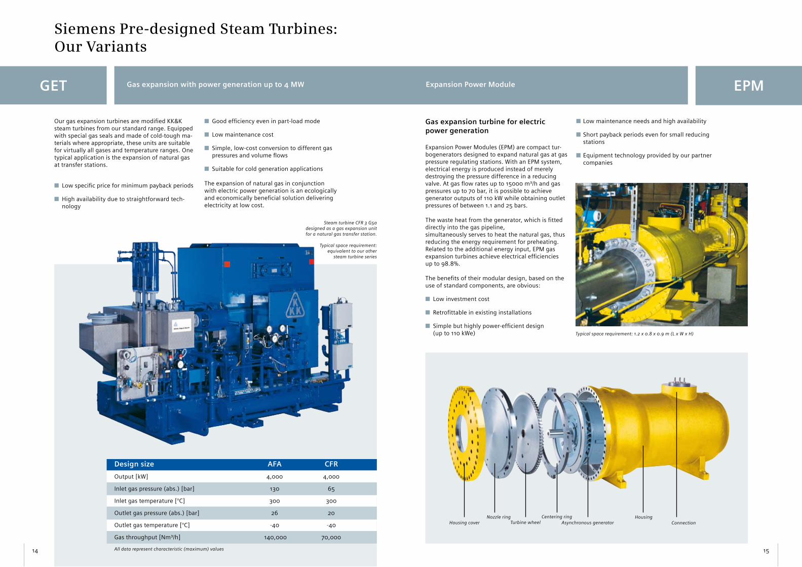
Gas expansion turbine for electric power generation
Expansion Power Modules (EPM) are compact tur-bogenerators designed to expand natural gas at gas pressure regulating stations. With an EPM system, electrical energy is produced instead of merely destroying the pressure difference in a reducing valve. At gas flow rates up to 15000 m³/h and gas pressures up to 70 bar, it is possible to achieve generator outputs of 110 kW while obtaining outlet pressures of between 1.1 and 25 bars.
The waste heat from the generator, which is fitted directly into the gas pipeline,simultaneously serves to heat the natural gas, thus reducing the energy requirement for preheating. Related to the additional energy input, EPM gas expansion turbines achieve electrical efficiencies up to 98.8%.
The benefits of their modular design, based on the use of standard components, are obvious:
n Low investment cost
n Retrofittable in existing installations
n Simple but highly power-efficient design (up to 110 kWe)
n Low maintenance needs and high availability
n Short payback periods even for small reducing stations
n Equipment technology provided by our partner companies
Typical space requirement: 1.2 x 0.8 x 0.9 m (L x W x H)
Housing coverNozzle ring
Turbine wheelCentering ring
Asynchronous generatorHousing
Connection
Siemens Pre-designed Steam Turbines: Our Variants
GET Gas expansion with power generation up to 4 MW
14
n Good efficiency even in part-load mode
n Low maintenance cost
n Simple, low-cost conversion to different gas pressures and volume flows
n Suitable for cold generation applications
The expansion of natural gas in conjunction with electric power generation is an ecologically and economically beneficial solution delivering electricity at low cost.
Our gas expansion turbines are modified KK&K steam turbines from our standard range. Equipped with special gas seals and made of cold-tough ma-terials where appropriate, these units are suitable for virtually all gases and temperature ranges. One typical application is the expansion of natural gas at transfer stations.
n Low specific price for minimum payback periods
n High availability due to straightforward tech- nology
Design size AFA CFR
Output [kW] 4,000 4,000
Inlet gas pressure (abs.) [bar] 130 65
Inlet gas temperature [°C] 300 300
Outlet gas pressure (abs.) [bar] 26 20
Outlet gas temperature [°C] -40 -40
Gas throughput [Nm³/h] 140,000 70,000
All data represent characteristic (maximum) values
Expansion Power Module
Steam turbine CFR 3 G5a designed as a gas expansion unit for a natural gas transfer station.
Typical space requirement: equivalent to our other
steam turbine series

ORC
17
For applications involving the generation of elec-tricity from renewable energies, e.g. geothermal systems in which heat is available at a low tem-perature level, we supply turbine technology that is based on steam power processes but relies on the use of organic operating media, i.e., the so-called organic rancine cycle (ORC).
In an ORC power system, a low-boiling organic operating medium circulates instead of water and ensures a maximum energy output at temperatures from 100°C upwards and pressures of less than 20 bar.
Our ORC turbines deliver electrical outputs of up to 1.5 MW and provide the same benefits as steam process systems (CRC).
n Simple technology involving low piping and equipment pressure ratings
n Easy-to-automate process sequences
n High efficiency
n Reduced investment and operating costs
n Low maintenance and servicing requirements
We supply solutions for this application type in cooperation with our partner company, GMK of Rostock/Germany.
Extraction well Injection well
Siemens Pre-designed steam turbine
Grid pump
Condenser
Feed pump
Evaporator
Electric power
Thermal power
Geothermally useful stratum
Generator
ORC application: geothermal plant
Siemens Pre-designed Steam Turbines: Our Variants
ECM Expansion Compression Module
16
Directly coupled compressor-turbine combination for power inputs up to 1500 kW
Each Expansion Compression Module (ECM) is a unitized combination of a compressor and a steam turbine mounted on a single shaft without any intermediate coupling. Each module comes with all mechanical and electrical control components.
Modules are built from standard pre-designed steam turbine and compressor assemblies.
The units are supplied rated for specific application requirements and are ready for connection.
Expanded compressor & turbine combi-nation options
Apart from ECMs we can supply a variety of integral compressor/turbine sets comprising compressors sourced from a member of our group and a driving turbine from our range.
Steam turbine AFA 6 Da driving a com-pressor for a refinery in Abu Dhabi
Compressor
Lubrication pump and oil cooler
Gear transmission
Turbine
ECMTypical space requirement: 2.2 x 2.0 x 2.6 m (L x W x H)
Organic Rancine Cycle
1
2
3
4
5
6
Turbine with generator Power data in kW
Recuperator Evaporator 9,700
Condenser Preheater 4,700
Evaporator and preheater Recuperator 2,800
Cooling tower Condenser 12,500
Grid coupling Generator 1,900

19
Measuring - Control - InstrumentationKK&K expertise for KK&K turbines
Gears and Electronics
Advanced electronic equipment contributes greatly to the performance of our turbine systems. We supply high-precision turbine control and monitor-ing technology. At the customer‘s request, we will advise on interfacing with overall process man-agement systems or can supply the entire turbine visualization system.
The above-mentioned services are based on DIN, EN, VDE and VDEW codes and standards. Planning and implementation will be handled in accordance with our proprietary electrical engineering guide-lines, taking existing customer specifications and national regulations into account.
Our range of electrical engineering products:
Terminal boxes, designed as
n Field interface boxes, mounted on equipment for
termination of actuators and sensors
Local control panels/consoles for
n Operation/MMI
n Control
n Monitoring
n Signal transfer and bus interfacing
Switchgear cabinets/panels for
n Operating and indicating functions
n Closed/open-loop control (PLC)
n Measuring and monitoring
n Electrical protection of turbogenerators
n Turbogenerator synchronization
n Mains and generator circuit breakers for low and
medium-voltage applications up to 12 kV
n Control and power supply for auxiliary drives
n Available in-house engineering
n Bus interfacing
n Remote maintenance
Operating and visualization stations
Siemens Pre-designed Steam Turbines: Spur Gear Transmissions
18
n High flexibility despite modular standardization
n Matched turbine and transmission technology based on our system competence
n Independence from external transmission vendors thanks to in-house fabrication
n Adaptability to diverse turbine speeds ensures high efficiency
n Transmission design and rating conforms to DIN 3990 and is based on calculations performed by our own engineers
n High manufacturing precision for maximum service life
n Worldwide customer support
We have accumulated many decades of experience in the fabrication of turbomachinery and transmis-sions. Over 12,000 transmissions built in-house by us have been delivered to satisfied customers to date.
Our single-stage spur gear units are capable of transmitting as much as 5 MW of power. Due to their rugged design, our transmissions can handle rotational speeds of up to 30,000 r.p.m. on the pinion shaft (depending on type) and are available with transmission ratios up to 1:17. Ground teeth, in conjunction with a correction of tooth contact sur-faces during assembly, ensure maximum operating smoothness and very low noise output in service. Their high mechanical precision and maintenance-free sliding bearings allow these gear units to oper-ate in both the subcritical and overcritical range.
Model G2a G3a G4a G5a G6a TWIN
Centre distance 225 321 399 544 630 1088-1154
Rotational speed (wheel shaft, max.) [r.p.m.] 10,000 5,000 4,000 3,600 3,600 3,000
Rotational speed (pinion, max.) [r.p.m.] 30,000 30,000 30,000 30,000 30,000 30,000
Transmission ratio 1.6-6.8 1.6-10.0 1.6-12.8 1.6-14.9 1.6-17.7 1.6-14.9
Power rating (max.) [kW] 2,000 2,000 2,500 3,000 4,000 5,000
Weight [kg] 1,100 1,350 1,700 2,500 3,000 2,750
Length [mm] 1,020 1,170 1,345 1,620 1,790 1,900
Width (not including coupling stubs) [mm] 650 650 650 650 650 650
Height [mm] 955 925 1,000 1,145 1,240 1,145
Measuring – Control – InstrumentationOur expertise for our steam turbines

Within this structure, optimized material flows and production workflows have given rise to the follow-ing key benefits:
nHigh content of „in-house“ manufactured components in every product
n Competitive price levels through domestic production („made in Germany“)
n Continuous expansion of know-how
n Maximum schedule reliability
nNo dependence on external suppliers
Our advanced, quality-focused production approach finds its outward expression in clean-cut and functionally structured manufacturing areas incorporating neatly arranged storage facilities for parts, jigs and fixtures.
Our overall concept and ongoing effort to ensure unsurpassed manufacturing precision is further supported by
n preventive equipment maintenance
ncoordinated repair strategies
21
Manufacturing Cells
Our steam turbines are produced by the most ad-vanced manufacturing technology in terms of both the equipment pool employed and the logistical control of all production workflows.
Component assembly or individual fabrication steps are performed or implemented in individual production cells operating on their own account.
The responsibility for organizing the specific process - e.g., planning, control, programming, resource management, manufacturing, testing and conveying - resides with the staff of each cell, whose key tasks specifically include quality control and time scheduling.
Given the high proportion of turbine components manufactured in-house, Siemens Pre-designed steam turbines achieve unsurpassed levels of qual-ity and reliability.
20
Advanced Production Technology with Quality Assurance

Quality, Service and Contacts
Each turbine or installation enjoys full global support based on our comprehensive range of after-sales services:
nFast spare part supplies
nRepairs and overhauls
nConversion and upgrading projects
nMaintenance and on-site erection
nMalfunction and vibration analysis
The reliability of this service derives from the following factors:
nSupport and execution by our own technicians
nAs-built documentation of all turbine installations
nAdvanced electronic aids and measuring technology
nExtensive know-how based on in-house fabrication
nCertified quality assurance
KK&K steam turbines:
Since November 2006 KK&K is part of Siemens, integrated into the division Oil&Gas and Industrial Applications.
Siemens Customer Support – Worldwide Reliability
23
Furthermore for the Customer support of our KK&K-machines the experienced experts are still available.
Individual agreements assure you of continuous maintenance support that will safeguard the longevity of your turbine equipment.
It may also be worth mentioning that we keep spare parts available for more than 30 years after the delivery of your machine.
Contact new units:
You can reach us during business hours Mon. - Fri. from 7:00 a.m. till 5:00 p.m.
Siemens TurbomachineryEquipment GmbHPre-designed Steam TurbinesHessheimer Strasse 267227 FrankenthalGermany
Phone +49 6233 85-2291Fax +49 6233 85-2660
E-mail: [email protected]
Contact also our website:www.siemens.com/agkkk
Certified Quality and Safety – for Every Machine
Our DIN EN ISO 9001 certified quality management system, backed up by a KTA 1401 qualification certificate, attests to our high quality standards for its products and services.
Quality assurance and test/inspection processes
Methods employed for quality assurance include the following:
• Dimensional testing (3D measurement, shape and position measurement, surface roughness measurement)• Electrical and mechanical run-out determination• Leak and pressure tests• Testing of mechanical properties• Material identity tests, chemical analysis, X-ray inspection, ultrasonic testing, surface crack tests (magnetic and by dye-penetration method)
Mechanical test run during final inspection
Each fully assembled unit must pass a no-load mechanical test run at full r.p.m.
The customer benefits through reduced on-site commissioning times.
Labour safety and environmental protection
We address health and labour safety as well as environmental impact issues with the same meticulous care as product quality. This commitment has won us SCC certification.
22
Contact service:
You can reach us during business hours Mon. - Fri. from 7:00 a.m. till 5:00 p.m.
On-site installation:Phone +49 6233 85-2314Fax +49 6233 85-2758
Customer support, after-sales service, spare parts store:Phone +49 6233 85-2418Fax +49 6233 85-2720
E-mail: [email protected]
Service Helpdesk (24 hours/day):+49 171 518 2610
Top Related