


Languages
Pages
Legal

Y-1954001
MKS Instruments Deutschland GmbH
Edition 2013-02
PR 4000B-S
Single Channel Controller
for Pressure Transducer,
Mass Flow Controller / Meter
Instruction Manual

MKS Products provided subject to the US Export Regulations. Diversion or transfer contrary to U.S. law is prohibited.
Copyright © 2008 by MKS Instruments Deutschland GmbH
All rights reserved. No part of this work may be reproduced or transmitted in any form or by any means, electronic or mechanical, including photocopying and recording, or by any information storage or retrieval system, except as may be expressly permitted in writing by MKS Instruments.
Printed in the Federal Republic of Germany

PR4000B-S Table of Contents
iii
Table of Contents
Safety Information ............................................................................................................................... 7
Symbols Used in This Instruction Manual ..................................................................................... 7
Safety Procedures and Precautions ............................................................................................. 8
Chapter 1: General Information ......................................................................................................... 9
1.1 General Description ........................................................................................................... 9
1.2 Customer Support ............................................................................................................. 9
1.3 Intended Use ................................................................................................................... 10
1.4 Symbols and Notes ......................................................................................................... 10
Chapter 2: Installation ...................................................................................................................... 11
2.1 Unpacking ....................................................................................................................... 11
2.2 Unpacking Checklist ........................................................................................................ 11
2.3 Cables ............................................................................................................................. 12
Interconnection Cables from MKS ................................................................................... 12
Generic Shielded Cable Description................................................................................ 13
2.4 Installation, Mounting ....................................................................................................... 14
Rack Mounting or Table Top? ......................................................................................... 14
Dimensions ...................................................................................................................... 15
Line Power and Fuses ..................................................................................................... 16
Connecting Cables .......................................................................................................... 16
2.5 Switching on the unit ....................................................................................................... 17
Chapter 3: Overview ........................................................................................................................ 19
3.1 Front Panel ...................................................................................................................... 19
3.2 Rear Panel ....................................................................................................................... 20
Connections..................................................................................................................... 20
3.3 Connectors ...................................................................................................................... 21
CHANNEL 1 .................................................................................................................... 21
EXTERN .......................................................................................................................... 21
ACCESS .......................................................................................................................... 22
RELAY ............................................................................................................................. 22
RS232 .............................................................................................................................. 22

Table of Contents PR4000B-S
iv
Chapter 4: Operation........................................................................................................................ 23
4.1. The operating concept ..................................................................................................... 23
Switching on Edit mode ................................................................................................... 23
Switching off Edit mode ................................................................................................... 23
Decimal point ................................................................................................................... 23
Switching the setpoint on and off ..................................................................................... 23
Programming via PC or terminal ..................................................................................... 24
Trigger functions .............................................................................................................. 24
Negative values ............................................................................................................... 24
4.2. Signal Processing ............................................................................................................ 24
4.3. Menus .............................................................................................................................. 25
Structure .......................................................................................................................... 25
Actual Value/Setpoint ...................................................................................................... 25
Actual Value/Bargraph ..................................................................................................... 26
Autozero .......................................................................................................................... 27
Setpoint/Range ................................................................................................................ 28
Gain/Offset ...................................................................................................................... 29
Input/Output-Voltage ....................................................................................................... 29
Maximum Limit/Minimum Limit ........................................................................................ 30
Limit Mode/Limit Memory ................................................................................................ 31
Limit Memory ................................................................................................................... 32
Reset Relays ................................................................................................................... 33
Signal Processing ............................................................................................................ 33
Sensor and Interface ....................................................................................................... 34
Device .............................................................................................................................. 35
Baud Rate and Parity ....................................................................................................... 35
Reset ............................................................................................................................... 36
Chapter 5: Special Functions ........................................................................................................... 37
5.1 Autozero .......................................................................................................................... 37
5.2 Process safeguarding ...................................................................................................... 37

PR4000B-S Table of Contents
v
Chapter 6: Typical Configurations .................................................................................................... 39
6.1. Mass Flow ....................................................................................................................... 39
How to configure and operate a Mass Flow Controller (MFC) for N2 .............................. 39
How to operate a MFC using the gas correction factor ................................................... 40
Master-Slave-Flow Ratio Control with two PR4000B-S ................................................... 41
6.2. Pressure .......................................................................................................................... 43
Chapter 7: External Communication ................................................................................................ 45
7.1. Interface RS 232 ............................................................................................................. 45
Parameters ...................................................................................................................... 45
7.2. Protocols.......................................................................................................................... 45
RS232 interface ............................................................................................................... 45
7.3. Commands ...................................................................................................................... 46
Structure of the Remote Interface Language .................................................................. 46
Special byte formats ........................................................................................................ 47
Status bytes of the PR4000 ............................................................................................. 48
Commands ...................................................................................................................... 49
Appendix A: Specifications .............................................................................................................. 67
MKS Worldwide Calibration & Service Centers ................................................................................ 69
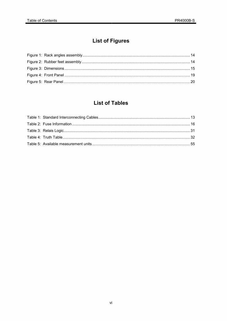
Table of Contents PR4000B-S
vi
List of Figures
Figure 1: Rack angles assembly ...................................................................................................... 14
Figure 2: Rubber feet assembly ....................................................................................................... 14
Figure 3: Dimensions ....................................................................................................................... 15
Figure 4: Front Panel ....................................................................................................................... 19
Figure 5: Rear Panel ........................................................................................................................ 20
List of Tables
Table 1: Standard Interconnecting Cables ....................................................................................... 13
Table 2: Fuse Information ................................................................................................................ 16
Table 3: Relais Logic........................................................................................................................ 31
Table 4: Truth Table ......................................................................................................................... 32
Table 5: Available measurement units ............................................................................................. 55

PR4000B-S Safety Information
7
Safety Information
Symbols Used in This Instruction Manual
Definitions of WARNING, CAUTION, and NOTE messages used throughout the manual.
Warning
The WARNING sign denotes a hazard. It calls attention to a
procedure, practice, condition, or the like, which, if not correctly
performed or adhered to, could result in injury to personnel.
Caution
The CAUTION sign denotes a hazard. It calls attention to an
operating procedure, practice, or the like, which, if not correctly
performed or adhered to, could result in damage to or destruction of
all or part of the product.
Note
The NOTE sign denotes important information. It calls attention to a
procedure, practice, condition, or the like, which is essential to highlight.

Safety Information PR4000B-S
8
Safety Procedures and Precautions
The following general safety precautions must be observed during all phases of operation of this
instrument. Failure to comply with these precautions or with specific warnings elsewhere in this
manual violates safety standards of intended use of the instrument and may impair the
protection provided by the equipment. MKS Instruments assumes no liability for the customer’s
failure to comply with these requirements.
DO NOT SUBSTITUTE PARTS OR MODIFY INSTRUMENT
Do not install substitute parts or perform any unauthorized modification to the instrument. Return the instrument to an MKS Calibration and Service Center for service and repair to ensure that all safety features are maintained.
SERVICE BY QUALIFIED PERSONNEL ONLY
Operating personnel must not remove instrument covers. Component replacement and internal adjustments must be made by qualified service personnel only.
GROUND THE PRODUCT AND USE PROPER ELECTRICAL FITTINGS
Dangerous voltages are contained within this instrument. All electrical fittings and cables must be of the type specified, and in good condition. All electrical fittings must be properly connected and grounded.
This product is grounded through the grounding conductor of the power cord. To avoid electrical shock, plug the power cord into a properly wired receptacle before connecting it to the product input or output terminals. A protective ground connection by way of the grounding conductor in the power cord is essential for safe operation.
DANGER ARISING FROM LOSS OF GROUND
Upon loss of the protective-ground connection, all accessible conductive parts (including knobs and controls that may appear to be insulating) can render an electrical shock.
USE THE PROPER POWER CORD
Use only a power cord that is in good condition and which meets the input power requirements specified in the manual.
Use only a detachable cord set with conductors that have a cross-sectional area equal to or greater
than 0.75 mm2. The power cable should be approved by a qualified agency such as VDE, Semko, or SEV.
PR4000B-S Chapter 1: General Information
9
Chapter 1: General Information
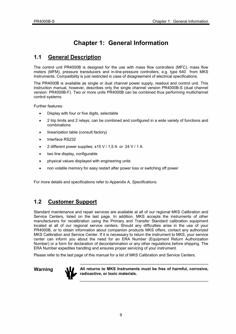
1.1 General Description
The control unit PR4000B is designed for the use with mass flow controllers (MFC), mass flow meters (MFM), pressure transducers and in-line-pressure controllers, e.g. type 640 from MKS Instruments. Compatibility is just restricted in case of disagreement of electrical specifications.
The PR4000B is available as single or dual channel power supply, readout and control unit. This instruction manual, however, describes only the single channel version PR4000B-S (dual channel version: PR4000B-F). Two or more units PR4000B can be combined thus performing multichannel control systems.
Further features:
• Display with four or five digits, selectable
• 2 trip limits and 2 relays, can be combined and configured in a wide variety of functions and combinations
• linearization table (consult factory)
• Interface RS232
• 2 different power supplies: ±15 V / 1,5 A or 24 V / 1 A
• two line display, configurable
• physical values displayed with engineering units
• non volatile memory for easy restart after power loss or switching off power
For more details and specifications refer to Appendix A, Specifications.
1.2 Customer Support
Standard maintenance and repair services are available at all of our regional MKS Calibration and Service Centers, listed on the last page. In addition, MKS accepts the instruments of other manufacturers for recalibration using the Primary and Transfer Standard calibration equipment located at all of our regional service centers. Should any difficulties arise in the use of your PR4000B, or to obtain information about companion products MKS offers, contact any authorized MKS Calibration and Service Center. If it is necessary to return the instrument to MKS, your service center can inform you about the need for an ERA Number (Equipment Return Authorization Number) or a form for declaration of decontamination or any other regulations before shipping. The ERA Number expedites handling and ensures proper servicing of your instrument.
Please refer to the last page of this manual for a list of MKS Calibration and Service Centers.
Warning
All returns to MKS Instruments must be free of harmful, corrosive,
radioactive, or toxic materials.

Chapter 1: General Information PR4000B-S
10
1.3 Intended Use
The PR4000B is a power supply and readout unit for operation of MKS mass flow meters, mass flow controllers, pressure transducers and in-line pressure controllers. Combination with units of other manufacturers may be possible given operating specifications that match MKS hardware requirements. However, MKS Instruments does not guarantee any warranty for these system configurations, and will not be liable for any consequential or incidental damages occurring through these combinations.
1.4 Symbols and Notes
1. The arrow → refers to a section, indicated in italics, in this manual which gives additional information.
2. N / A stands for ‚not applicable’.
3. Special versions are not described in this document.

PR4000B-S Chapter 2: Installation
11
Chapter 2: Installation
2.1 Unpacking
MKS has carefully packed the Type PR4000B unit so that it will reach you in perfect operating order. Upon receiving the unit, however, you should check for defects, cracks, broken connectors, etc., to be certain that damage has not occurred during shipment.
Note
Do not discard any packing materials until you have completed your
inspection and are sure the unit arrived safely.
If you find any damage, notify your carrier and MKS immediately. Please refer to the last page of this manual for a list of MKS calibration and service centers.
Caution
Only qualified individuals should perform the installation and any
user adjustments. They must comply with all the necessary ESD and
handling precautions while installing and adjusting the instrument.
Proper handling is essential when working with all highly sensitive
precision electronic instruments.
2.2 Unpacking Checklist
Standard Equipment:
• PR4000B-S power supply & readout unit
• 4 rubber feet for tabletop use
• 2 replacement fuses
• Power cable
• Instruction manual (this document)
Optional:
• Connection cable(s), e.g. for transducers, controllers etc.

Chapter 2: Installation PR4000B-S
12
2.3 Cables
The unit complies with the European standards and thus it is labeled with the CE-mark. To fulfill the above listed guidelines it is mandatory to use the appropriate interconnection cables.
Note
The instrument complies to EN 61326-2-2 with the requirements for industrial applications. Braided shielded cables must be used. We recommend to use the cables offered by MKS Instruments.
Cables which are in compliance with the CE guidelines are marked with an „E“ or „S“ (example: CB259E-... or CB259S-...).
Interconnection Cables from MKS
The following table lists the standard cables provided by MKS Instruments. They are all in compliance with the CE guidelines. If the cable needed for your particular instruments is not listed there then please contact your MKS center.
The cable length is 3 meters (standard length), 5 m or 10 m (optional).
For cable length greater than 10 m please contact your MKS center.
(continued on next page)

PR4000B-S Chapter 2: Installation
13
Cables for combination with the PR4000 with +/- 15 VDC power supply1
For pressure transducers or in-line pressure controllers
type or series
MKS-Cable Type
120
121
622, 623, 624, 625, 223, 122A
621, 626, 627, 628, 127, 128, 722A (with 15-pin type D connector)
722 (9-pin type D connector)
722 (terminal block)
CBE 120-96-3M
CBE 112-14-3M
CBE 112-2-3M
CBE 259-5-3M
CBE 700-1-3M
CBE 700-99-3M
CBE 259-5-3M
CBE147-12-3M
For mass flow meters (MFM) or mass flow controllers (MFC)
with 15-pin type D connector:
179, 1179, 2179,1479, 1259, 2259, 258, 358, 1359, 558, 1559, M100
with 9-pin type D connector:
1179, 2179, 1479, M200, M330
Table 1: Standard Interconnecting Cables for the PR 4000 with +/- 15 VDC power supply
Note
Flow controllers with 9-pin connector do not have the „Valve Close“ input (remotely closing of the control valve).
Generic Shielded Cable Description
MKS offers a full line of cables for all MKS equipment. Should you choose to manufacture your own cables, follow the guidelines listed below:
1. The cable must have a braided shield, covering all wires. Neither aluminum foil nor spiral shielding will be as effective; using either may nullify regulatory compliance.
2. The connectors must have a metal case which has direct contact to the cable’s shield on the whole circumference of the cable. The inductance of a flying lead or wire from the shield to the connector will seriously degrade the shield’s effectiveness. The shield should be grounded to the connector before its internal wires exit.
3. With very few exceptions, the connector(s) must make good contact to the device’s case (ground). “Good contact” is about 0.01 ohms; and the ground should surround all wires. Contact to ground at just one point may not suffice.
4. For shielded cables with flying leads at one end; it is important at such end, to ground the shield before the wires exit. Make this ground with absolute minimum length. After picking up the braid’s ground, keep wires and braid flat against the case. With very few exceptions, grounded metal covers are not required over terminal strips. If one is required, it will be stated in the Declaration of Conformity or in the instruction manual.
1 For connection cables fort the PR4000 with 24 VDC power supply please contact MKS.

Chapter 2: Installation PR4000B-S
14
5. In selecting the appropriate type and wire size for cables, consider:
a. The voltage ratings;
b. The cumulative I2R heating of all the conductors (keep them safely cool);
c. The IR drop of the conductors, so that adequate power or signal voltage gets to the device;
d. The capacitance and inductance of cables which are handling fast signals, (such as data lines or stepper motor drive cables); and
e. That some cables may need internal shielding from specific wires to others; please see the instruction manual for details regarding this matter.
2.4 Installation, Mounting
The PR4000B-S is designed for use in dry and warm environment with sufficient ventilation. The device must be installed in such a way that air can circulate free. Do not cover the openings at the instrument’s housing. If there are heat loss generating devices located next to the unit make sure that no excessive heat is transferred to the unit.
Rack Mounting or Table Top?
The PR4000B fits to a 19“ half rack or maybe used on top of a table. Three screws on each side allow disassembling of the rack angles. Rubber feet give the device a stable stand on a table. (Screws are TX10)
Figure 1: Rack angles assembly Figure 2: Rubber feet assembly
Note
Position the unit with proper clearance to allow air cooling, so that the unit can operate within the specified temperature as listed in appendix A. Do not cover the openings at the instrument’s housing.

PR4000B-S Chapter 2: Installation
15
Dimensions
241
226
18,85 203,3 18,85
76
,2
88
86
185
Figure 3: Dimensions
(above: Front and Rear Panel; below: Side View)
Chapter 2: Installation PR4000B-S
16
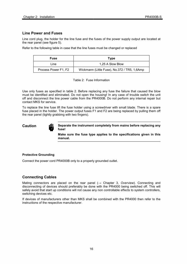
Line Power and Fuses
Line cord plug, the holder for the line fuse and the fuses of the power supply output are located at the rear panel (see figure 5).
Refer to the following table in case that the line fuses must be changed or replaced
Fuse Type
Line 1,25 A Slow Blow
Process Power F1, F2 Wickmann (Little Fuse), No.372 / TR5, 1,6Amp
Table 2: Fuse Information
Use only fuses as specified in table 2. Before replacing any fuse the failure that caused the blow must be identified and eliminated. Do not open the housing! In any case of trouble switch the unit off and disconnect the line power cable from the PR4000B. Do not perform any internal repair but contact MKS for service.
To replace the line fuse lift the fuse holder using a screwdriver with small blade. There is a spare fuse placed in the holder. The power output fuses F1 and F2 are being replaced by pulling them off the rear panel (tightly grabbing with two fingers).
Caution
Separate the instrument completely from mains before replacing any
fuse!
Make sure the fuse type applies to the specifications given in this
manual.
Protective Grounding
Connect the power cord PR4000B only to a properly grounded outlet.
Connecting Cables
Mating connectors are placed on the rear panel (→ Chapter 3, Overview). Connecting and disconnecting of devices should preferably be done with the PR4000 being switched off. This will safely avoid that start up conditions will not cause any non controllable effects to system controllers, switching devices etc.
If devices of manufacturers other than MKS shall be combined with the PR4000 then refer to the instructions of the respective manufacturer.

PR4000B-S Chapter 2: Installation
17
2.5 Switching on the unit
After all connections to the peripheral instruments, e.g. pressure transducer, mass flow controller etc. are properly done the unit can be switched on. Refer to the instructions for the peripheral units for proper installation, connection, set up and warm up.
Note
Before switching on the PR4000 make sure that this does not cause any negative effects to other instruments or to the system control. This is mostimportant when the unit is switched on the first time after installation.
After switching on via the main power switch on the rear panel or the button POWER on the front panel, respectively, the following readout appears after 2-3 seconds:
(shown: version 2.10 of June 18, 2008)
Then the unit switches automatically to the first window (display 1) for operation (→ chapter 4: Operation).
The control elements and their function are briefly described in the following chapter 3, Overview.
PR4000 1CHANNEL
V 2.10 Juni 18,08

Chapter 2: Installation PR4000B-S
18
This page left blank.

PR4000B-S Chapter 3: Overview
19
Chapter 3: Overview
3.1 Front Panel
On/off switches for setpoint
Power switch Enter key Escape key
ENTER
Arrow keys for dialog selection
OFF
PR4000B
POWER ESC
Display
ON
LED for setpoint
LED for remote operation
Contrast adjustment
CONTRAST
REMOTE
SETPOINT
Figure 4: Front Panel
Display: Two lines. Can be configured by user.
POWER Button switch toggles between standby and operation. For total separation from mains use switch on the rear side. The LED above indicates the device in operation. Setup is stored with power being switched off.
ENTER Accepts and stores entered data.
ESC (Escape) Switches stepwise back finally to display Actual Value/Setpoint
Arrow buttons Navigation in the menues
ON , OFF Switches the setpoint output to a mass flow controller or pressure controller.
SETPOINT LED, lit when setpoint output is active.
REMOTE LED, lit when unit is operated through serial interface.
CONTRAST Allows adjustment of display contrast.

Chapter 3: Overview PR4000B-S
20
3.2 Rear Panel
The rear panel provides all connectors, the fuse holder and the receptable for the line voltage cable.
ACCESS
EXTERN
RELAY
CHANNEL1
RS232
SERVICE
F1
F2
IO
MAIN PWR
LINE IN
FUSE
Figure 5: Rear Panel
Connections
ACCESS Connector ACCESS. Direct access to the pins for input and output signals, setpoint and controls of the connector CHANNEL 1.
EXTERN This connection is used to input external analog setpoint signal and to monitor the measurement signal.
RELAY Access to the contacts of both relays.
CHANNEL 1 Connection for pressure transducer, mass flow controller etc.
RS232 Serial Interface RS232
SERVICE Service and Diagnostics (used only by MKS)
LINE IN Receptable for line power cord
MAIN PWR I = On; unit can be toggled on and off by front panel button switch 0 = Off; front panel button switch disabled.
F1, F2 Fuses 1,6 A for power output ± 15 V or 24 V, respectively
FUSE Line fuse (compartment with replacement fuse)
For detailed information to fuses refer to chapter 2 Line Power and Fuses.
PR4000B-S Chapter 3: Overview
21
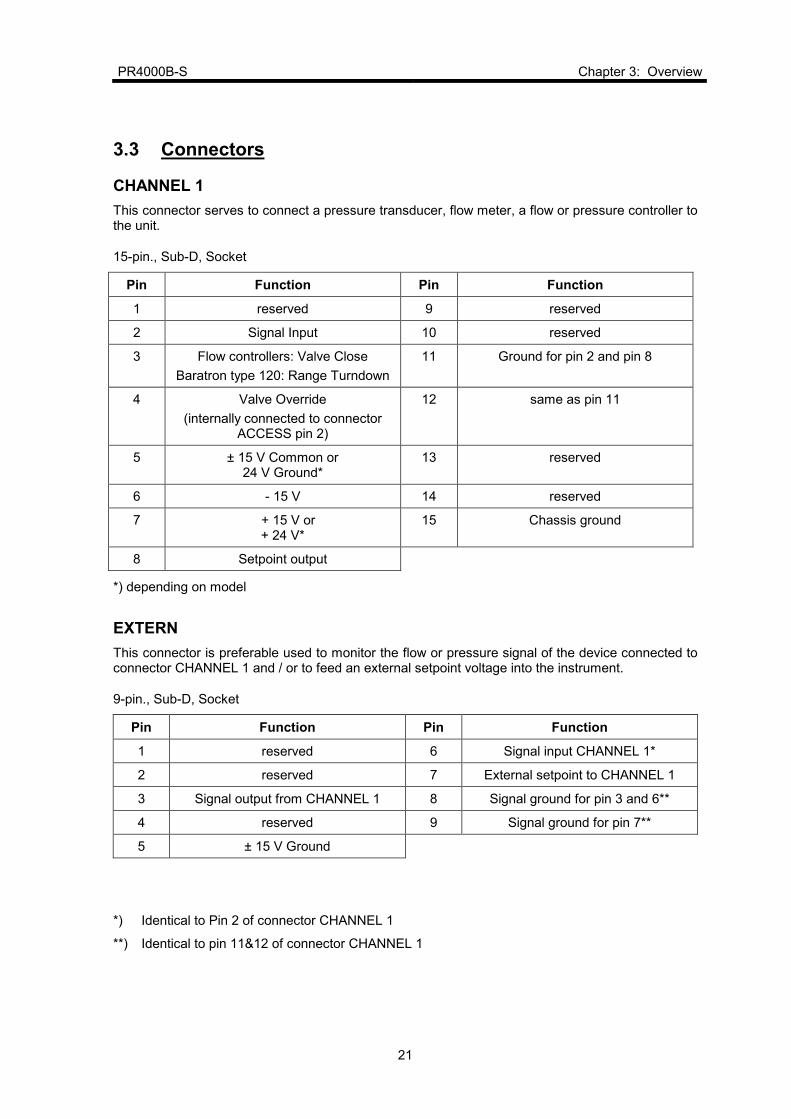
3.3 Connectors
CHANNEL 1
This connector serves to connect a pressure transducer, flow meter, a flow or pressure controller to the unit.
15-pin., Sub-D, Socket
Pin Function Pin Function
1 reserved 9 reserved
2 Signal Input 10 reserved
3 Flow controllers: Valve Close
Baratron type 120: Range Turndown
11 Ground for pin 2 and pin 8
4 Valve Override
(internally connected to connector ACCESS pin 2)
12 same as pin 11
5 ± 15 V Common or 24 V Ground*
13 reserved
6 - 15 V 14 reserved
7 + 15 V or + 24 V*
15 Chassis ground
8 Setpoint output
*) depending on model
EXTERN
This connector is preferable used to monitor the flow or pressure signal of the device connected to connector CHANNEL 1 and / or to feed an external setpoint voltage into the instrument.
9-pin., Sub-D, Socket
Pin Function Pin Function
1 reserved 6 Signal input CHANNEL 1*
2 reserved 7 External setpoint to CHANNEL 1
3 Signal output from CHANNEL 1 8 Signal ground for pin 3 and 6**
4 reserved 9 Signal ground for pin 7**
5 ± 15 V Ground
*) Identical to Pin 2 of connector CHANNEL 1
**) Identical to pin 11&12 of connector CHANNEL 1
Chapter 3: Overview PR4000B-S
22
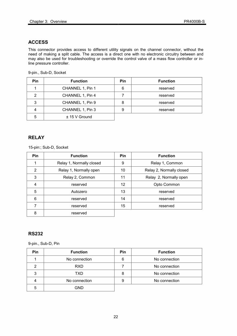
ACCESS
This connector provides access to different utility signals on the channel connector, without the need of making a split cable. The access is a direct one with no electronic circuitry between and may also be used for troubleshooting or override the control valve of a mass flow controller or in-line pressure controller.
9-pin., Sub-D, Socket
Pin Function Pin Function
1 CHANNEL 1, Pin 1 6 reserved
2 CHANNEL 1, Pin 4 7 reserved
3 CHANNEL 1, Pin 9 8 reserved
4 CHANNEL 1, Pin 3 9 reserved
5 ± 15 V Ground
RELAY
15-pin:; Sub-D, Socket
Pin Function Pin Function
1 Relay 1, Normally closed 9 Relay 1, Common
2 Relay 1, Normally open 10 Relay 2, Normally closed
3 Relay 2, Common 11 Relay 2, Normally open
4 reserved 12 Opto Common
5 Autozero 13 reserved
6 reserved 14 reserved
7 reserved 15 reserved
8 reserved
RS232
9-pin., Sub-D, Pin
Pin Function Pin Function
1 No connection 6 No connection
2 RXD 7 No connection
3 TXD 8 No connection
4 No connection 9 No connection
5 GND
PR4000B-S Chapter 4: Operation
23
Chapter 4: Operation
4.1. The operating concept
The PR4000 is operated and configured by means of menus (two-line LCD). The menus are
organized in a simple hierarchy (→ 4.3 Menus, Structure). All the menus can be accessed and displayed easily: you can step from one menu to another using the up/down arrow keys or return to the main menu at any time by pressing the ESC key.
Switching on Edit mode
Edit mode can be switched on or off in the menus. You can enter numeric values in Edit mode, alter variables, etc. There are two ways of switching on Edit mode:
1. With the ENTER key
2. With the left/right arrow keys
When you switch on Edit mode, the cursor appears as a flashing underscore below the first or last alphanumeric character. You can move the cursor within a line using the left/right arrow keys or change the preset values with the up/down arrow keys.
If '9' is displayed and you press the up/down arrow keys again to scroll the number, the display automatically creates two digits ('10'); the same applies analogously in the opposite direction.
If, when you exit Edit mode by pressing the ENTER key, the value you have set is outside the valid range, the highest or lowest permitted value is stored instead.
Switching off Edit mode
You can leave Edit mode again by pressing the ENTER key. The entered values are not stored until you press the ENTER key.
You can also exit Edit mode with the ESC key. In this case, however, the values are not stored.
Decimal point
The decimal point is needed to display floating-point numbers and can be set with the Range (RNG) function in the Setpoint menu. You can mark the decimal point in this menu with the left/right arrow keys and shift it with the up/down keys. The up arrow shifts the cursor to the left, while the down arrow shifts it to the right. The new decimal point setting takes effect in all the menus in which measured values or values directly referred to them are displayed. It does not affect device parameters, such as Gain.
Switching the setpoint on and off
You can switch the setpoint of a controller on and off with the ON and OFF keys. The OFF key has the highest priority of all keys for safety reasons. As soon as you switch off the setpoint, the output voltage becomes slightly negative (-0.5 V). This ensures that if a valve is fitted, it is closed.

Chapter 4: Operation PR4000B-S
24
Programming via PC or terminal
All the values which appear on the display refer to processes that are taking place at a particular instant in time. Values that are programmed with a PC or terminal (connected to the digital interface) are displayed immediately. Example: If the setpoint is reprogrammed via the interface, this change is displayed instantly in all the menus concerned.
The keypad can be locked while you program with a PC or terminal.
Trigger functions
Trigger functions (functions which trigger an immediate system response) are displayed immediately (DONE or FAIL). The display time is 0.5 seconds.
Negative values
Negative values are displayed with a preceding minus sign. To enter a negative value, you must continue scrolling when the value 'zero' is displayed. All values from then on will have a negative sign. You can change negative values to positive values in the same way.
4.2. Signal Processing
The signal processing program carries out the following steps:
1. The setpoint is normalized.
2. The measured value (input) is normalized and the binary value is converted to a floating-point number.
3. The measured value (normalized input) is corrected with the gain and offset factors and normalized according to the following formula:
Normalized actual value = GAIN * (normalized Input - OFFSET)
FSIN
4. The display mode of the actual value is defined (e.g. linear).
5. The setpoint is output, corrected with the gain, FSIN, FSOUT and offset factors and renormalized according to the following formula:
Output = (
normalized Setpoint + OFFSET
)* FSOUT
GAIN FSIN
6. The actual value is displayed.
If the setpoint then fails to reach a value greater than zero or if the setpoint switch is set to OFF, a constant output voltage of -500 mV is output. This ensures that if a valve is open, it is closed safely.

PR4000B-S Chapter 4: Operation
25
4.3. Menus
Structure
The PR4000 has the following menus:
1. Actual Value/Setpoint 9. Limit Mode/Limit Memory
2. Actual Value/Bargraph 10. Reset Relays
3. Autozero 11. Signal Processing Mode
4. Setpoin/Range 12. Sensor and Interface
5. Gain/Offset 13. Device
6. Linearization (optional) 14. Baudrate and Parity
7. Input/Output Voltage 15. Reset
8. Maximum Limit/Minimum Limit
The menu structure is linear; there are no branches to submenus.
To get quickly back from any menu to the main display Actual Value/Setpoint as shown next, simply press the button ESC (Escape)!
Actual Value/Setpoint
PRES 00.000 mbar
SETP 02.000 OFF
Actual Value/Setpoint menu
The first line shows the currently valid sensor value. The word 'PRES' indicates that the displayed value refers to the pressure of a pressure sensor. It is also possible to connect a flow controller (FLOW) or a temperature sensor (TEMP), etc. You can change the display mode in the Sensor menu.
The measured value is shown in millibar. You can set a different measurement unit in the Setpoint menu.
The second line allows you to switch the setpoint on and off. In this example the setpoint is set to OFF. You can also alter the value of the setpoint right here by switching on Edit mode (with the ENTER key) and then increasing or reducing the setpoint value with the up and down arrow keys, respectively.
Chapter 4: Operation PR4000B-S
26
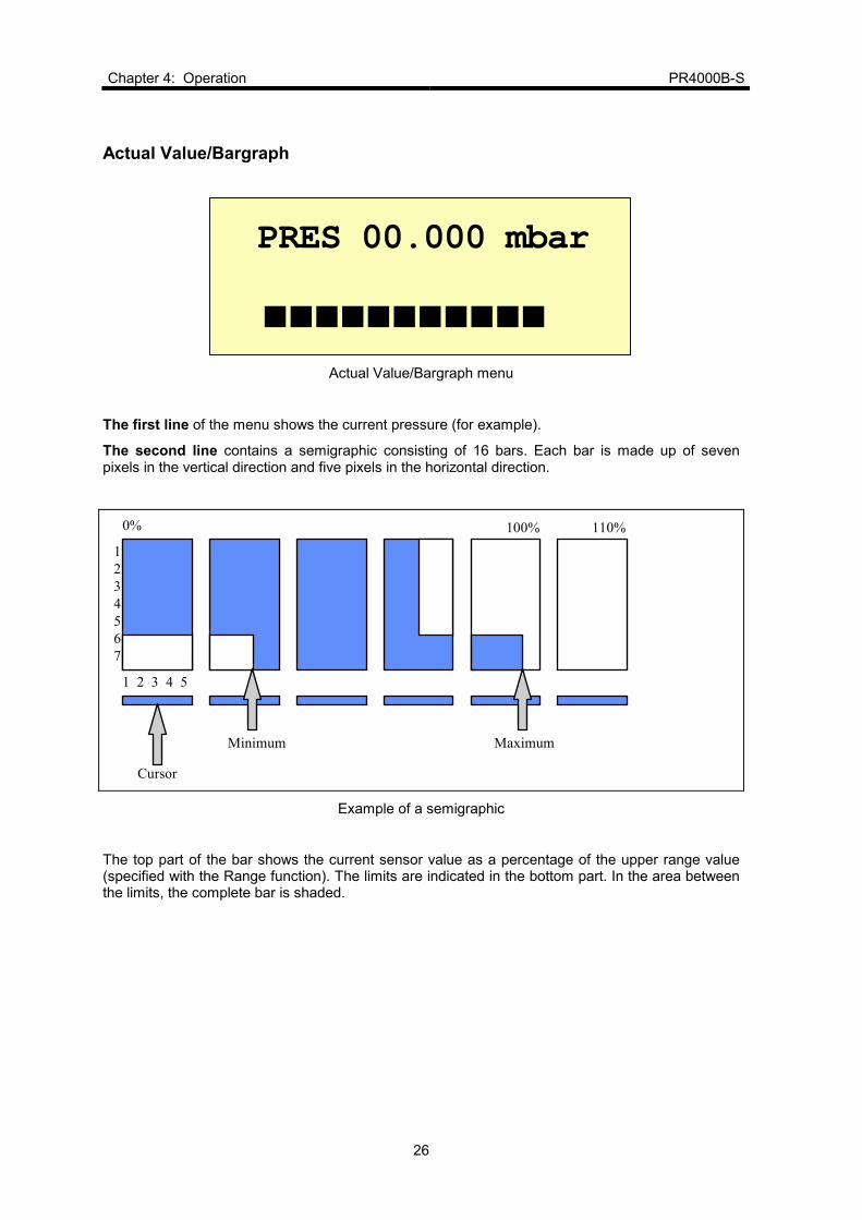
Actual Value/Bargraph
PRES 00.000 mbar
Actual Value/Bargraph menu
The first line of the menu shows the current pressure (for example).
The second line contains a semigraphic consisting of 16 bars. Each bar is made up of seven pixels in the vertical direction and five pixels in the horizontal direction.
1
2
3
4
5
6
7
1 2 3 4 5
Cursor
Minimum Maximum
0% 100% 110%
Example of a semigraphic
The top part of the bar shows the current sensor value as a percentage of the upper range value (specified with the Range function). The limits are indicated in the bottom part. In the area between the limits, the complete bar is shaded.

PR4000B-S Chapter 4: Operation
27
Autozero
AUTO ZERO
Autozero menu
The autozero function can be activated in this menu. To do so, switch on Edit mode and press the ENTER key. The system message 'DONE' then appears briefly to indicate that the autozero function was performed. You can only activate this function if the setpoint is switched off. If you attempt to activate autozero with the setpoint switched on, the word 'FAIL' will appear on the display.

Chapter 4: Operation PR4000B-S
28
Setpoint/Range
SETP 00.000 SCCM
RNG 00.000 SCCM
Setpoint/Range menu
You can set the value of the setpoint in the first line.
The measurement unit, the range value and the decimal point can be set in the second line.
You must switch on EDIT mode in order to change the measurement unit. You can then mark the unit and select a new one with the up/down arrow keys.
Changing the measurement unit
You can set the following measurement units in the second line:
Available measurement units
ubar mbar bar
mTor Torr kTorr
Pa kPa
mH2O cH2O PSI N/qm
SCCM SLM SCM SCFH SCFM
mA V % C
Setting the decimal point
For details of how to set the decimal point, please refer to chapter 4.1 The Operating Concept.
Note:
If you shift the decimal point, the change takes effect in all the menus in which measured values or values directly referred to them are displayed. It does not affect device parameters, such as Gain.

PR4000B-S Chapter 4: Operation
29
Gain/Offset
GAIN 0.0000
OFFS 0000 mV
Gain/Offset menu
You can define correction values in the Gain menu.
You can set the gain value (e.g. the gas correction factor) in the first line. This factor corrects the deviation of a gas flow controller if a gas other than N
2 is used.
The second line displays the value which is valid for the autozero function. You can also set the offset manually here. The offset is the fault voltage which is subtracted from the measured value.
Input/Output-Voltage
FSIN 10000 mV
FSOUT 10000 mV
Input/Output Voltage menu
You can set the value of the voltage that corresponds to the full-scale of the device connected to the connector CHANNEL1.
FSIN line: full scale voltage in milliVolts of the device (normally shown on its label).
FSOUT line: full scale voltage of the setpoint output in milliVolts.

Chapter 4: Operation PR4000B-S
30
Maximum Limit/Minimum Limit
MAXL 00.000 bar
MINL 00.000 bar
The Maximum Limit/Minimum Limit menu
This menu serves to define the limit values (maximum and minimum) for limit monitoring (relays).
You can only set the values here, not the engineering units.

PR4000B-S Chapter 4: Operation
31
Limit Mode/Limit Memory
LIMIT MODE SLEEP
LIMIT MEMORY OFF
Limit Mode/Limit Memory menu
In the first line the limit mode can be set to one of the following:
SLEEP, LIMIT, or BAND.
SLEEP
No processes are monitored in SLEEP mode.
LIMIT
LIMIT mode is used to monitor the gas flow, to make sure it remains within the permitted operating limits. If the gas flow rises above the maximum limit or falls below the minimum limit, the corresponding relay is activated. The device interprets limit values as absolute values in LIMIT mode.
BAND
This mode is similar to LIMIT mode, except that the limit values are interpreted as deviations from the setpoint. The minimum limit represents a negative deviation.
Monitoring starts two seconds after a mode has been selected.
The relay logic depends on the active monitoring mode:
Mode Relay condition
SLEEP Relay 1 (low relay) represents the (valve) status of the channel.
Relay 2 (high relay) is always inactive.
BAND Relay 1 (low relay) represents the (valve) status of the channel.
Relay 2 (high relay) is activated if the actual gas flow is outside the defined band.
LIMIT Relay 1 (low relay) is activated as soon as the gas flow falls below the specified minimum limit.
Relay 2 (high relay) is activated as soon as the gas flow rises above the specified maximum limit.
Table 3: Relais Logic

Chapter 4: Operation PR4000B-S
32
Mode Relay Valve Minimum
limit
violated
Maximum
limit
violated
Relay
condition
SLEEP 1 OFF X X Inactive
SLEEP 1 ON X X Active
SLEEP 2 X X X Inactive
BAND 1 OFF X X Inactive
BAND 1 ON X X Active
BAND 2 X NO NO Inactive
BAND 2 X X YES Active
BAND 2 X YES X Active
LIMIT 1 X NO X Inactive
LIMIT 1 X YES X Active
LIMIT 2 X X NO Inactive
LIMIT 2 X X YES Active
Table 4: Truth Table
X = Any
There is a hysteresis of 0.5 % of full scale, before the relays will switch back.
Limit Memory
Limit Memory in the second line can be set to the ON or OFF status. This memory stores a non-recurrent limit violation. If the limit memory is set to ON, it registers a single violation of a limit value. Even if the limit is exceeded several times, only one violation is registered.
The meanings of the states ON / OFF are as follows:
Limit memory OFF The relays reflect the actual condition. They are activated if the limit value is exceeded. If the measured value returns to within the permitted limits, the relays are deactivated again.
Limit memory ON If the limit value is violated just once in either direction, a relay is activated and remains active. It can be reset with the reset function in the Reset Relays menu.

PR4000B-S Chapter 4: Operation
33
Reset Relays
RESET RELAYS
Reset Relays menu
Activating RESET RELAYS causes the trip limit relays to be reset (trigger function) if the limit memory option is set to ON in the Limit Mode/Limit Memory menu.
Signal Processing
SIG.MODE INDEP.
DISPLAY DIRECT
Processing Mode menu
The signal processing mode (SIG. MODE) can be set in the first line to either independent (INDEP.) or external (EXTERNAL). EXTERNAL means that the setpoint is preset externally as an analog value via the EXTERNAL interface (pin 7). INDEP. means that the setpoint (SETP) is preset via the keyboard or via the digital interface.
The second line can not be changed.

Chapter 4: Operation PR4000B-S
34
Sensor and Interface
SENSOR PRES
IFACE RS232
Sensor and Interface menu
The following sensor types can be set in the first line:
Display for
PRES Pressure sensor
FLOW Flow controller
VOLT Voltage
TEMP Temperature sensor
VAL Any
No display
You can only change the sensor display mode in this menu. The sole purpose of the setting is to label the menu; it is not evaluated internally in any other way.
The sensor type is followed by the letter P (pressure) or F (flow). This letter indicates the connector assignment that has been configured in the PR4000.
The second line indicates the interface RS232.

PR4000B-S Chapter 4: Operation
35
Device
RS232 ADR. --
RS232 MODE --
Device menu
(no changes possible)
Baud Rate and Parity
BAUD RATE 9600 Bd
PARITY ----
Baud Rate and Parity menu
The following data transfer baud rates can be set in the first line:
110 1200 2400 4800 9600 19k2 38k4 57k6 76k8 115k
You cannot alter the baud rate of the OPTION interface.
In the second line you can set the parity. The parity can be NONE, EVEN or ODD.

Chapter 4: Operation PR4000B-S
36
Reset
RES: SYS LIN STS
STATUS: R
Reset menu
The first line (RES) indicates which parameters can be reset. You must return to Edit mode in order to do so.
Display Result
SYS Resets the complete system to the default parameters
LIN Resets the linearization parameters, i.e. sets a straight line
STS Resets the status bits in the second line
Error displays can only be reset by means of STS.
The following STATUS can be shown in the second line:
Display Meaning
T Transmission error (on the serial interface)
O Overflow error (the AD converter has reached its saturation limit)
R Range error (value outside 0 - 110 % range)
H High relay (active)
L Low relay (active)
The letters 'H' and 'L' for high and low relay are only displayed if the relays are active.

PR4000B-S Chapter 5: Special Functions
37
Chapter 5: Special Functions
5.1 Autozero
The autozero function can only be selected if the setpoint is set to OFF.
It causes the instantaneous measured value to be adopted as the offset. The zero value is corrected computationally with this offset (error). The correction algorithm is described in detail in section 4.2 Signal Processing.
You can activate the autozero function via the digital interface (only if the setpoint is set to OFF).
5.2 Process safeguarding
When the device is switched on (e.g. when the POWER switch on the front panel is set to ON), all the interface signals present at this time are initially inactive (the setpoint is set to -0.5 V and the relays remain inactive).
When the device is switched off (e.g. when the Power switch on the front panel is set to OFF), all the output channels are deactivated and remain inactive.

Chapter 5: Special Functions PR4000B-S
38
This page left blank.

PR4000B-S Chapter 6: Typical Configurations
39
Chapter 6: Typical Configurations
The following examples show typical configurations, combinations and operations of the PR4000B-S with some (but not all) instruments. In any case the user is obliged to read and understand also the instructions in the manuals of the respective device the PR4000B-S is used with.
6.1. Mass Flow
How to configure and operate a Mass Flow Controller (MFC) for N2
• Device:
MFC: 1179, 1479, 1559, 1579, others with analog input/output
Range: 500 sccm (N2)
Output signal: 0-5 VDC
Process gas: N2 or Air
• Setup:
Connect the MFC to PR4000 via the cable CBE259-5XM. In case of MKS MFC’s with 9-pin D-connector the cable type CBE147-12-XX must be used.
• Settings:
- in the menu SETPOINT the RNG to 500.00 SCCM and SETP to the desired gas flow, in this example to 100.00 sccm:
- in the menu GAIN the value of GAIN to 1.0000
- in the menu INPUT/OUTPUT-VOLTAGE set FSIN and FSOUT to 05000 mV
- in the menu SIGNAL PROCESSING MODE set SIG.MODE to INDEP .
- in the menu SENSOR AND INTERFACE set SENSOR to FLOW
FSIN 05000mV FSOUT 05000mV
GAIN 1.0000 OFFS 0000 mV
SETP 100.00 SCCM RNG 500.00 SCCM
SIG.MODE INDEP. DISPLAY DIRECT
SENSOR FLOW F IFACE RS232
PR4000
N2
CB259-5-3M
MFC

Chapter 6: Typical Configurations PR4000B-S
40
• Zero Adjustment:
Allow the MFC to thermally stabilize (refer to the MFC’s manual). Ensure that no gas flow occurs. When both requirements are fullfilled you can perform the zero adjustment in the menu AUTOZERO by means of the autozero function. Alternatively the zeroing can be done manually in the menu GAIN, line OFFS by entering an appropriate value.
• Start/Stop:
Start or stop gas flow either by pushing the ON/OFF button or by using the menu ACTUAL VALUE/SETPOINT, line SET.
How to operate a MFC using the gas correction factor
• Device:
MFC: 1179, 1479, 1559, 1579, others with analog input/output
Range: 500 sccm (N2)
Output signal: 0-5 VDC
Process gas: CO2
• Setup
Connect the MFC to PR4000 via the cable CBE259-5XM. In case of MKS MFC’s with 9-pin D-connector the cable type CBE147-12-XX must be used.
• Settings:
Use the same settings as in the previous example but use the menu GAIN to apply the correction factor for the gas in use. For CO2 you find in the manual of the MFC the gas correction factor the value 0,70 (can be different depending of device). Set GAIN to this value.
This allows the PR4000 to display the gas flow and enter the setpoint directly in engineering units without the need for further conversion. In this example the full scale range of the MFC is now limited to 500 sccm x 0,7 = 350sccm. As the PR4000 allows the operation up to 110 % the useable range however is 350 sccm x 1,1 = 385 sccm.
GAIN 0.7000 OFFS 0000 mV
PR4000
CO2
CB259-5-3M
MFC

PR4000B-S Chapter 6: Typical Configurations
41
Master-Slave-Flow Ratio Control with two PR4000B-S
PR4000 Master PR4000 Slave
MFC1
MFC2
CO2
2N
2CO 2/N
CB259-5-3M
• Device :
two MFC’s type 1179, V.
Ranges: a) Master 500 SCCM
b) Slave 200 SCCM
Output signal: 0-5 VDC
Process gases: a) Master CO2
b) Slave N2
Controllers: two PR4000B-S
Cables: two CBE259-5-3M
Interconnecting cable from master to slave
• Setup:
Connect each MFC to its PR4000 control unit and connect the PR4000 slave to the PR4000 master as shown:
PR4000 Master PR4000 Slave
EXTERN EXTERN
Pin Pin
analog out 3 7 external setpoint
signal GND 8 9 signal GND
power GND 5 5 power GND

Chapter 6: Typical Configurations PR4000B-S
42
• Settings:
Use the same settings as in the previous example with these exceptions for the slave:
• set in the menu SIGNAL PROCESSING MODE the SIG.MODE to EXTERN
This de-activates setpoint settings in the ACTUAL VALUE/SETPOINT menu. The display there however, shows now the value of the external setpoint combined with the scalingfactor SCL. Note: Choosing the external control signal changes SETPOINT in the SETPOINT menu to SCL.
• Calculation of the scaling factor SCL:
Formula:
Master full scale range x Master/Slave – Ratio = Scaling factor SCL (Slave)
Examples for flow ratio calculation:
Master MFC full scale: 350 sccm CO2 Slave MFC full scale: 200 sccm N2
a) Desired ratio: Master 100 sccm / Slave 100 sccm
Ratio = 1
Set setpoint at PR4000-Master to 100 sccm
Set scaling factor SCL at PR4000-Slave to 350 sccm
b) Desired ratio: Master 250 sccm / Slave 50 scc
Ratio = 1/ 5
Set setpoint at PR4000-Master to 250 sccm
Set setpoint at PR4000-Slave to 70 sccm
SIG.MODE EXTERN DISPLAY DIRECT
PR4000B-S Chapter 6: Typical Configurations
43
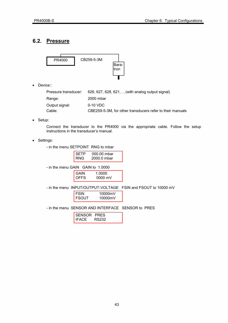
6.2. Pressure
• Device::
Pressure transducer: 626, 627, 628, 621, V(with analog output signal)
Range: 2000 mbar
Output signal: 0-10 VDC
Cable: CBE259-5-3M, for other transducers refer to their manuals
• Setup:
Connect the transducer to the PR4000 via the appropriate cable. Follow the setup instructions in the transducer’s manual.
• Settings:
- in the menu SETPOINT RNG to mbar
- in the menu GAIN GAIN to 1.0000
- in the menu INPUT/OUTPUT-VOLTAGE FSIN and FSOUT to 10000 mV
- in the menu SENSOR AND INTERFACE SENSOR to PRES
FSIN 10000mV FSOUT 10000mV
GAIN 1.0000 OFFS 0000 mV
SETP 000.00 mbar RNG 2000.0 mbar
SENSOR PRES IFACE RS232
PR4000 CB259-5-3M
Bara- tron
Chapter 6: Typical Configurations PR4000B-S
44
Zero adjust of the pressure transducer (refer also to the transducer’s manual)
To correctly adjust the zero signal of the pressure transducer the following conditions must be fulfilled:
1. transducer mounted in its final position
2. thermally stabilized
3. zero pressure exists, e.g. in case of an absolute gage the transducer must be evacuated below its resolution ( typically 0,01 % of full scale or 0,001 % of full scale, depending of type). In case of a differential pressure transducer equal pressure must exist at both ports.
When all requirements are fulfilled you can perform the zero adjustment in the menu AUTOZERO by means of the autozero function. Alternatively the zeroing can be done manually in the menu GAIN, line OFFS by entering an appropriate value.
Note
When editing the zero offset value in the GAIN menu the setting will be stored after switching off the unit. For most types of capacitance manometers however, it is recommended to check the zero signal after re-powering and re-adjust if necessary.
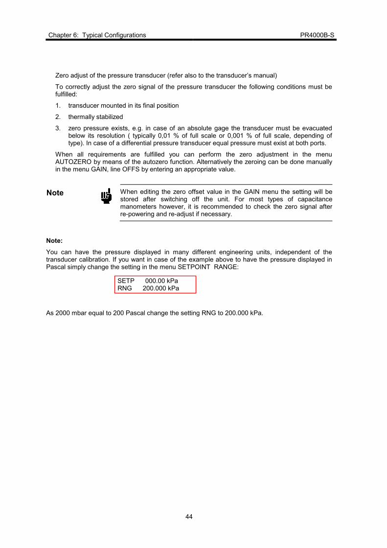
Note:
You can have the pressure displayed in many different engineering units, independent of the transducer calibration. If you want in case of the example above to have the pressure displayed in Pascal simply change the setting in the menu SETPOINT RANGE:
As 2000 mbar equal to 200 Pascal change the setting RNG to 200.000 kPa.
SETP 000.00 kPa RNG 200.000 kPa

PR4000B-S Chapter 7: External Communication
45
Chapter 7: External Communication
7.1. Interface RS 232
The RS 232 interface is standard on each PR4000B-S.
Parameters
Address (Device menu): Not used Mode (Device menu): Not used Baud rate (Baud Rate and Parity menu): Used Parity (Baud Rate and Parity menu): Used 7 data bits and 1 stop bit
Requests and commands are always transferred in blocks, rather than as individual characters.
Refer to chapter 7 for detailed user information.
7.2. Protocols
RS232 interface
The protocol is a simple command/answer sequence with no buffering. The various commands and answers are described in detail in chapter 7.3 Commands. If the language definition does not include a defined answer, a dummy answer is sent: CR (carriage return, hex 0x0D).
A command answer, CR (carriage return, hex 0x0D) is returned. The carriage return is also used as a tail character. The maximum message length is 12 characters; separators such as blanks, tabs, etc. are not allowed. It is advisable to keep strictly to the ASCII formats.
An RS232 telegram consists of a send text, a received text and a tail character:
stxt CR
rtxt CR

Chapter 7: External Communication PR4000B-S
46
7.3. Commands
Structure of the Remote Interface Language
The Remote Interface Language allows to communicate with the PR4000 via the actual interface by for example a PC. This language has a simple command reply structure. All commands may be transmitted either in (a special) binary format or as ASCII code.
The elements of the syntax description is shown here:
stxt: Send text (from PC)
rtxt: Received text (to PC)
[[[[]]]] Optional element (e.g. [A] means A is optional) | Alternative of different elements (e.g. A|B means A or B)
@xxx: Bytes with fixed format (e.g. @cmd) (float): Binary format of a value 0x0004 Hexadecimal numeric format
Examples for ASCII formats:
BYTE: 000 Decimal string of three characters WORD: +00000 Decimal string of five characters and a sign LONG: 000000.0000 Floating point with eleven characters FLOAT: +0.00000 Floating point with six characters and a sign
How to handle byte formats:
p d6 d5 d4 d3 d2 d1 d0
The first bit of each byte is the parity bit and cannot be reprogrammed. The second bit is normally a one, in order to get a printable character. The bits d5 to d0 can be used for programming.
If, for example, the bits d4 and d2 should be set, you get this binary representation: 01010100b which is equal to the hexadecimal value: 0x54. If go through a ASCII table with this value, you will get the character ‘T’, which may be entered right on the command line. Some simple parameters are shown as hex. Constants, e.g. 0x31. In this case enter the corresponded ASCII character ‘1’ on the command line.

PR4000B-S Chapter 7: External Communication
47
Special byte formats
@cmd:
p 1 d5 d4 d3 d2 d1 d0
Only one of bits d5 - d2 is allowed to be set at any given time. If several bits are set, only the one with the highest priority is taken into account. Bit d5 has the highest priority and bit d2 the lowest priority.
The bits have the following meanings when set:
p: Parity bit
d5: Actual value sent
d4: Setpoint (external) sent
d3: Totalized value (total gas flow over a defined period of time) displayed
d2: Digital I/O sent
d1. Setpoint set to ON or OFF
d0: Totalizer (gas counter) reset
A total of four bytes are available for binary transfers - one header byte and three useful data bytes.
Special binary format
@head
p 1 b3d7 b3d6 b2d7 b2d6 b1d7 b1d6
@byte 1
p 1 b1d5 b1d4 b1d3 b1d2 b1d1 b1d0
@byte 2
p 1 b2d5 b2d4 b2d3 b2d2 b2d1 b2d0
@byte 3
p 1 b3d5 b3d4 b3d3 b3d2 b3d1 b3d0
The header byte is filled with:
bits 7 and 6 of byte 3 = bits 5 and 6,
bits 7 and 6 of byte 2 = bits 3 and 4,
bits 7 and 6 of byte 1 = bits 1 and 2.
Chapter 7: External Communication PR4000B-S
48
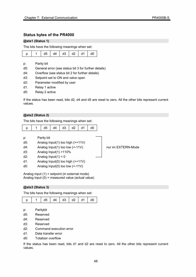
Status bytes of the PR4000
@sts1 (Status 1)
The bits have the following meanings when set:
p 1 d5 d4 d3 d2 d1 d0
p: Parity bit
d5: General error (see status bit 3 for further details)
d4: Overflow (see status bit 2 for further details)
d3: Setpoint set to ON and valve open
d2: Parameter modified by user
d1. Relay 1 active
d0: Relay 2 active
If the status has been read, bits d2, d4 and d5 are reset to zero. All the other bits represent current values.
@sts2 (Status 2)
The bits have the following meanings when set:
p 1 d5 d4 d3 d2 d1 d0
p: Parity bit
d5: Analog Input(1) too high (>+11V)
d4: Analog Input(1) too low (<-11V) nur im EXTERN-Mode
d3: Analog Input(1) >110%
d2: Analog Input(1) < 0
d1. Analog Input(0) too high (>+11V)
d0: Analog Input(0) too low (<-11V)
Analog input (1) = setpoint (in external mode) Analog input (0) = measured value (actual value)
@sts3 (Status 3)
The bits have the following meanings when set:
p 1 d5 d4 d3 d2 d1 d0
p: Paritybit
d5: Reserved
d4: Reserved
d3: Reserved
d2: Command execution error
d1. Data transfer error
d0: Totalizer overflow
If the status has been read, bits d1 and d2 are reset to zero. All the other bits represent current values.

PR4000B-S Chapter 7: External Communication
49
@sts4 (Status 4)
The bits have the following meanings when set:
p 1 d5 d4 d3 d2 d1 d0
p: Parity bit
d5: Digital input 5, reserved
d4: Digital input 4, reserved
d3: Digital input 3, start leak test
d2: Digital input 2, reset integrator
d1. Digital input 1, autozero
d0: Digital input 0, valve ON/OFF
d0 to d5 are the actual digital inputs.
The digital inputs are also transferred together with the measured value by the command 0x22 (direct access).
Commands
Command syntax
The binary float format conforms to IEEE 754. The command syntax and notation are described in more detail in chapter 7.3. Structure of the Remote Interface Language. Commands and answers are represented as follows in this chapter:
stxt: Text sent by master
rtxt: Answer from PR4000
Commands begin with the hexadecimal number corresponding to an ASCII character (e.g. 0x23). This is followed by the ASCII character itself (e.g. (#)) and finally a plain text description of the command ('Start signal processing').
Bytes in commands are abbreviated as 'b'. Example: setpoint.b3 denotes byte 3.
In the command 'head, setpoint.b3, setpoint.b2, 0x00head, setpoint.b1, setpoint.b0, 0x00', 'setpoint' consists of 8 bytes: 2x@head, setpoint.b3, setpoint.b2, setpoint.b1, setpoint.b0, 2x 0x00, whereby the value of the last byte is zero because it is not used.
Example:
The master (PC) sends 10 bytes in this example: command, @cmd, 8 bytes for the setpoint (optional). The binary format of the setpoint consists of 4 bytes (floating-point number in accordance with IEEE 754). The following answers are possible, depending on the bits which are set in @cmd:
measured value (actual value) or setpoint or DigOutDigIn or optionally the totalized value.

Chapter 7: External Communication PR4000B-S
50
General commands
0x21 (!) Update all values
stxt: 0x21@cmd [setpoint]
txt: @sts1 [actual value]|[setpoint]|[DigOut/DigIn]|[totalized value]
Setpoint:
Binär (float): @head, setpoint.b3, setpoint.b2, 0x00 @head, setpoint.b1, setpoint.b0, 0x00
ASCII FLOAT
Measured value (actual value):
Binär (float): @head, actual value.b3, actual value.b2, 0H, @head, actual value.b1, actual value.b0, 0x00
ASCII FLOAT
Setpoint:
Binär (float): @head, setpoint.b3, setpoint.b2, 0x00, @head, setpoint.b1, setpoint.b0, 0x00
ASCII FLOAT
DigOut/DigIn (8 bits DigOut, 8 bits DigIn):
Binär (unsigned): @head, 0x00, DigOut/DigIn
ASCII: WORD
DigIn Bit
VALVE ON/OFF db0
AUTOZERO db1
RESET TOTALIZER db2
START LEAK TEST db3
ONE|OUT db4
FLOW|PRES db5
OPTIONAL db6
OPTIONAL db7
DigOut Bit
RELAY0 db0
RELAY1 db1
CAL SWITCH0 db2
CAL SWITCH1 db3
OPTIONAL db4
CLOSE VALVE db5
OPTIONAL(PDR) db6
OPTIONAL(PDR) db7
Totalized value (optional):
Binary: Cf. ASCII
ASCII: LONG

PR4000B-S Chapter 7: External Communication
51
0x22 (“) Direct access to sensors
This command writes directly in the digital/analog converter and stops signal processing. A restart can be initiated with command 0x23.
stxt: 0x22 Outgoing data
rtxt: Incoming data
Outgoing data:
ASCII Not applicable
out = Output channel 1 out2 = Output channel 2
Incoming data:
Binary (float): @head, in.b1, in.b0, DigIn, @head, in2.b1, in2.b0, @
ASCII Not applicable
in = Input channel 1 in2 = Input channel 2 0x000 = Full-scale deflection; 0xFFFF = + full-scale deflection.
0x23 (#) Start signal processing
stxt: 0x23
rtxt: CR (carriage return; no return)
Commands 0x21 and 0x24 also start signal processing.
0x24 ($) Update sensor
stxt: 0x24 Setpoint
rtxt: Measured value (actual value)
Setpoint:
Binary (float): @head, setpoint.b3, setpoint.b2, 0x00, @head, setpoint.b1, setpoint.b0, 0x00
ASCII FLOAT
Measured value (actual value):
Binary (float): @head, actual value.b3, actual value.b2, 0x00, @head, actual value.b1, actual value.b0, 0x00
ASCII FLOAT

Chapter 7: External Communication PR4000B-S
52
0x25 (%) Change format
This command switches the format between binary and ASCII.
stxt: 0x25 nfrmt
rtxt: CR (carriage return; no return)
nfrmt:
0x30 = Binary (special binary format)
0x31 = ASCII
0x26 (&) Read status byte 1
stxt: 0x26
rtxt: @sts1
0x27 (‘) Read status byte 2
stxt: 0x27
rtxt: @sts2
0x28 (() Read status byte 3
stxt: 0x28 Reset when the byte is read
rtxt: @sts3
0x29 ()) Read status byte 4
stxt: 0x29 Reset when the byte is read
rtxt: @sts4
0x2A(*) Reset system to default values
stxt: 0x2A
rtxt: CR (carriage return; no return)
0x2B(+) Reset linearization (optional)
stxt: 0x2B
rtxt: CR (carriage return; no return)
0x2C (,) Reset relay
stxt: 0x2C
rtxt: CR (carriage return; no return)

PR4000B-S Chapter 7: External Communication
53
0x2D (-) Reset status 3
stxt. 0x2D
rtxt: CR (carriage return; no return)
0x2E (.) Reset totalizer
stxt: 0x2E
rtxt: CR (carriage return; no return)
0x2F (/) Start leak test
stxt: 0x2F
rtxt: CR (carriage return; no return)
0x30 (0) Autozero
This function interprets the actual measured value as zero and calculates a new offset.
stxt: 0x30
rtxt: CR (carriage return; no return)
0x31 (1) Autofullscale
This function interprets the actual measured value as the full-scale deflection and calculates a new gain.
stxt: 0x31
rtxt: CR (carriage return; no return)
0x32 (2) Autolinearization
This function interprets the actual measured value as the Y-value for linearization (optional).
stxt: 0x32 Interpolation point
rtxt: CR (carriage return; no return)
Interpolation point:
Binary, ASCII: (@ + value)
X-value for linearization
Chapter 7: External Communication PR4000B-S
54
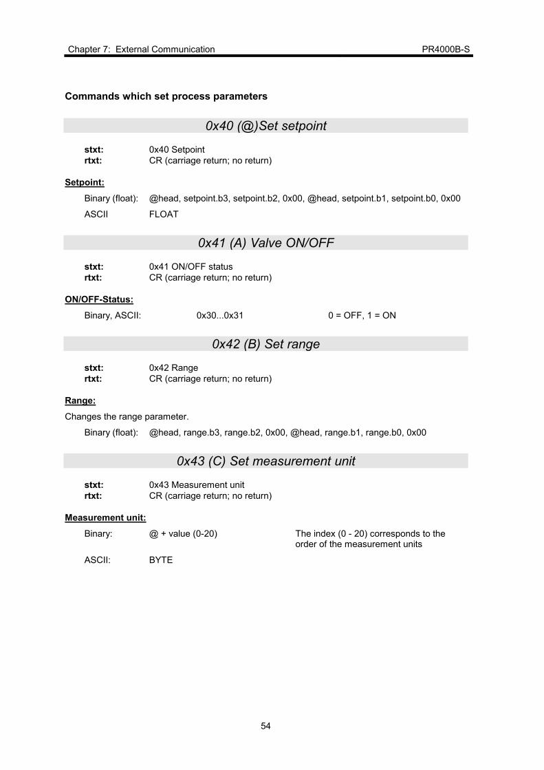
Commands which set process parameters
0x40 (@)Set setpoint
stxt: 0x40 Setpoint
rtxt: CR (carriage return; no return)
Setpoint:
Binary (float): @head, setpoint.b3, setpoint.b2, 0x00, @head, setpoint.b1, setpoint.b0, 0x00
ASCII FLOAT
0x41 (A) Valve ON/OFF
stxt: 0x41 ON/OFF status
rtxt: CR (carriage return; no return)
ON/OFF-Status:
Binary, ASCII: 0x30...0x31 0 = OFF, 1 = ON
0x42 (B) Set range
stxt: 0x42 Range
rtxt: CR (carriage return; no return)
Range:
Changes the range parameter.
Binary (float): @head, range.b3, range.b2, 0x00, @head, range.b1, range.b0, 0x00
0x43 (C) Set measurement unit
stxt: 0x43 Measurement unit
rtxt: CR (carriage return; no return)
Measurement unit:
Binary: @ + value (0-20) The index (0 - 20) corresponds to the order of the measurement units
ASCII: BYTE

PR4000B-S Chapter 7: External Communication
55
You can set the following measurement units:
Available measurement units
µbar=0 mbar=1 bar=2
mTorr=3 Torr=4 kTorr=5
Pa=6 kPa=7
mH2O=8 cH2O=9 PSI=10 N/qm=11
SCCM/CC=12 SLM/L=13 SCM/CM=14 SCFH/CF=15 SCFM/CF=16
mA=17 V=18 %=19 C=20
Table 5: Available measurement units
mHG == kTorr, mmHg == Torr CC = cubic centimeter, L = liter, CM = cubic meter, CF = cubic foot
0x44 (D) Set gain
stxt: 0x44 Gain
rtxt: CR (carriage return; no return)
Gain:
Binary (float): @head, gain.b3, gain.b2, 0x00, @head, gain.b1, gain.b0, 0x00
ASCII: FLOAT
0x45(E) Set offset
stxt: 0x45 Offset
rtxt: CR (carriage return; no return)
Offset:
Binary (integer): @head, 0x00, offs.b1, offs.b0
ASCII: WORD
0x46 (F) Set linearization table (optional)
stxt: 0x46 Reference Y-axis
rtxt: CR (carriage return; no return)
Reference:
Binary: (@+ value) X-value for linearization (0 - 10)
ASCII: BYTE
Important: This reference format is mandatory!
Y-axis:
Binary (float): @head, ylin.b3, ylin.b2, 0x00, @head, ylin.b1, ylin.b0, 0x00
ASCII: FLOAT

Chapter 7: External Communication PR4000B-S
56
0x47 (G) Set full-scale deflection for input voltage
stxt: 0x47 fsin Changes the FSIN parameter
rtxt: CR (carriage return; no return)
Input voltage:
Binary (unsigned): @head, 0x00, fsin.b1, fsin.b0
ASCII: WORD
0x48 (H) Set measurement unit for input voltage
stxt: 0x48 Measurement unit
rtxt: CR (carriage return; no return)
Input voltage measurement unit:
Binary. ASCII: 0x30...0x36
You can set the following measurement units for FSIN (input voltage):
mV µµµµA µµµµA 2 µµµµA 5 µµµµA 4 µµµµA 24 µµµµA 54
100Ω 200Ω 500Ω 100Ω 200Ω 500Ω
0 - 20 mA interface 4 - 20 mA interface
The index (0 - 6) corresponds to the order of the units.
0x49 (I) Set full-scale deflection for output voltage
stxt: 0x49 fsout
rtxt: CR (carriage return; no return)
Output voltage:
Changes the FSOUT parameter
Binary (unsigned @head, 0x00, fsout.b1, fsout() ASCII: WORD
0x4A (J) Set measurement unit for output voltage
stxt: 0x48 Measurement unit of output voltage
rtxt: CR (carriage return; no return)
Output voltage measurement unit:
Binary. ASCII: 0x30...0x31 mV and µA are the valid measurement units for FSOUT
PR4000B-S Chapter 7: External Communication
57
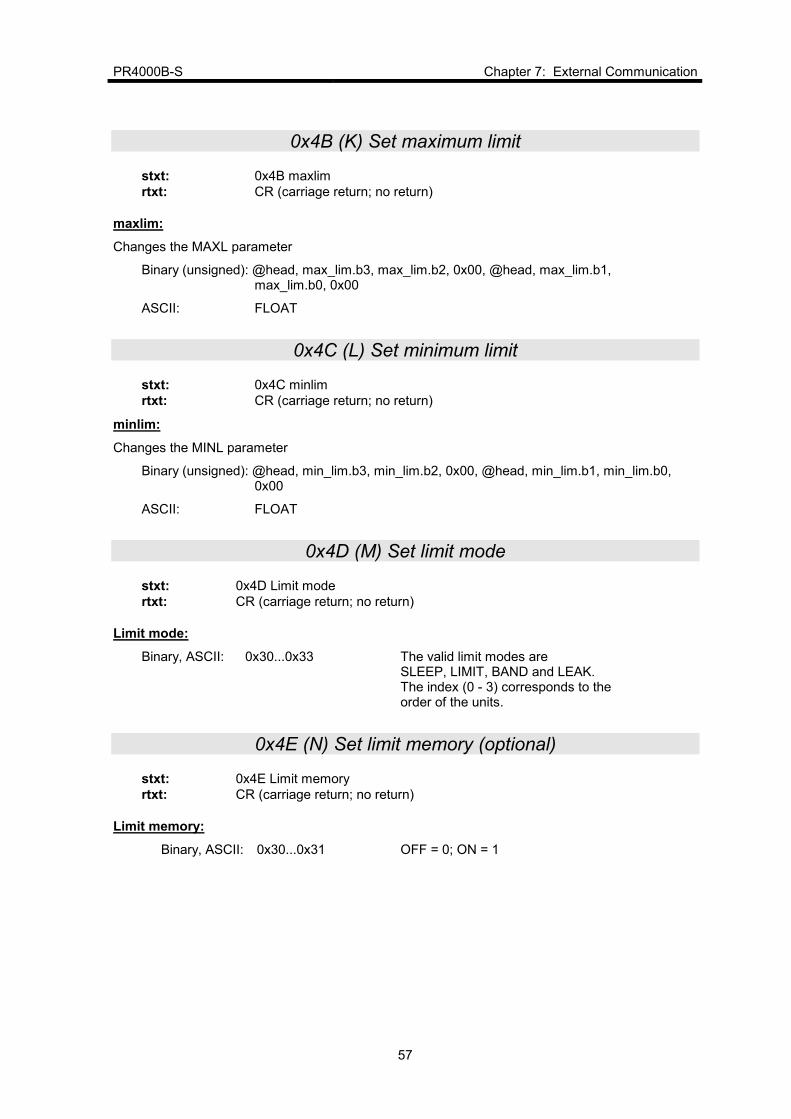
0x4B (K) Set maximum limit
stxt: 0x4B maxlim
rtxt: CR (carriage return; no return)
maxlim:
Changes the MAXL parameter
Binary (unsigned): @head, max_lim.b3, max_lim.b2, 0x00, @head, max_lim.b1, max_lim.b0, 0x00
ASCII: FLOAT
0x4C (L) Set minimum limit
stxt: 0x4C minlim
rtxt: CR (carriage return; no return)
minlim:
Changes the MINL parameter
Binary (unsigned): @head, min_lim.b3, min_lim.b2, 0x00, @head, min_lim.b1, min_lim.b0, 0x00
ASCII: FLOAT
0x4D (M) Set limit mode
stxt: 0x4D Limit mode
rtxt: CR (carriage return; no return)
Limit mode:
Binary, ASCII: 0x30...0x33 The valid limit modes are SLEEP, LIMIT, BAND and LEAK. The index (0 - 3) corresponds to the order of the units.
0x4E (N) Set limit memory (optional)
stxt: 0x4E Limit memory
rtxt: CR (carriage return; no return)
Limit memory:
Binary, ASCII: 0x30...0x31 OFF = 0; ON = 1

Chapter 7: External Communication PR4000B-S
58
0x4F (O) Set timeout (optional)
stxt: 0x4F Timeout in seconds
rtxt: CR (carriage return; no return)
Timeout
Binary (unsigned): @head, 0x00, timeout.b1, timeoutb
ASCII: WORD
0x50 (P) Set signal processing mode
stxt: 0x50 Signal processing mode
rtxt: CR (carriage return; no return)
Signal processing mode:
Binary, ASCII: 0x30...0x31 Index for signal processing mode: 0 = independent, 1 = extern
0x51 (Q) Set display mode
stxt: 0x51 Display
rtxt: CR (carriage return; no return)
Display:
Binary, ASCII: 0x30...0x31 Index for display mode (0..1) 0 = direct; 1 = linearized
0x52 (R) Set sensor type
stxt: 0x52 Sensor type
rtxt: CR (carriage return; no return)
Day of measured value:
Binary, ASCII: 0x30...0x36 Index for sensor type (0)
You can set the following sensor types:
Display Sensor type Setting
PRES Pressure sensor 0
FLOW Flow controller 1
VOLT Voltage 2
CURR Current 3
TEMP Temperature sensor 4
VAL Any 5
No display 6
PR4000B-S Chapter 7: External Communication
59
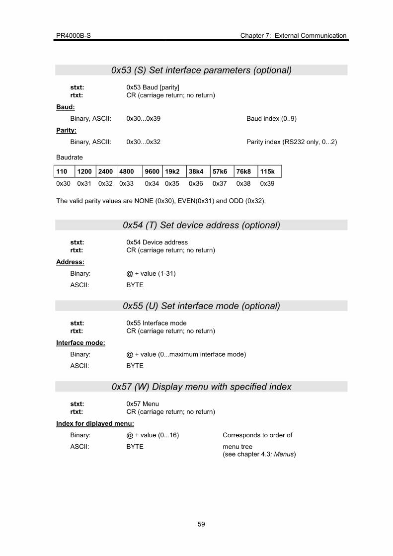
0x53 (S) Set interface parameters (optional)
stxt: 0x53 Baud [parity]
rtxt: CR (carriage return; no return)
Baud:
Binary, ASCII: 0x30...0x39 Baud index (0..9)
Parity:
Binary, ASCII: 0x30...0x32 Parity index (RS232 only, 0...2)
Baudrate
110 1200 2400 4800 9600 19k2 38k4 57k6 76k8 115k
0x30 0x31 0x32 0x33 0x34 0x35 0x36 0x37 0x38 0x39
The valid parity values are NONE (0x30), EVEN(0x31) and ODD (0x32).
0x54 (T) Set device address (optional)
stxt: 0x54 Device address
rtxt: CR (carriage return; no return)
Address:
Binary: @ + value (1-31)
ASCII: BYTE
0x55 (U) Set interface mode (optional)
stxt: 0x55 Interface mode
rtxt: CR (carriage return; no return)
Interface mode:
Binary: @ + value (0...maximum interface mode)
ASCII: BYTE
0x57 (W) Display menu with specified index
stxt: 0x57 Menu
rtxt: CR (carriage return; no return)
Index for diplayed menu:
Binary: @ + value (0...16) Corresponds to order of
ASCII: BYTE menu tree (see chapter 4.3; Menus)
Chapter 7: External Communication PR4000B-S
60
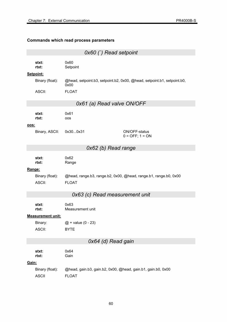
Commands which read process parameters
0x60 (`) Read setpoint
stxt: 0x60
rtxt: Setpoint
Setpoint:
Binary (float): @head, setpoint.b3, setpoint.b2, 0x00, @head, setpoint.b1, setpoint.b0, 0x00
ASCII: FLOAT
0x61 (a) Read valve ON/OFF
stxt: 0x61
rtxt: oos
oos:
Binary, ASCII: 0x30...0x31 ON/OFF-status 0 = OFF; 1 = ON
0x62 (b) Read range
stxt: 0x62
rtxt: Range
Range:
Binary (float): @head, range.b3, range.b2, 0x00, @head, range.b1, range.b0, 0x00
ASCII: FLOAT
0x63 (c) Read measurement unit
stxt: 0x63
rtxt: Measurement unit
Measurement unit:
Binary: @ + value (0 - 23)
ASCII: BYTE
0x64 (d) Read gain
stxt: 0x64
rtxt: Gain
Gain:
Binary (float): @head, gain.b3, gain.b2, 0x00, @head, gain.b1, gain.b0, 0x00
ASCII FLOAT

PR4000B-S Chapter 7: External Communication
61
0x65 (e) Read offset
stxt: 0x65
rtxt: Offset
Setpoint:
Binary: (int) @head, 0x00, offs.b1, offs.b0
ASCII: FLOAT
0x66 (f) Read linearization table
stxt: 0x66 Reference
rtxt: ylin
Reference:
Binär: @ + value (0...23) Inverse curve from K onwards
ASCII. BYTE
ylin:
Binary (float): @head, ylin.b3, ylin.b2, 0x00, @head, ylin.b1, ylin.b0, 0x00
ASCII: FLOAT
0x67 (g) Read full-scale deflection of input voltage
stxt: 0x67
rtxt: Full-scale deflection of input voltage
Full-scale deflection of input voltage:
Binary (integer): @head, 0x00, fsin.b1, fsin.b0
ASCII: WORD
0x68 (h) Read measurement unit of input voltage
stxt: 0x68
rtxt: Measurement unit of input voltage
Measurement unit of input voltage:
Binary, ASCII: 0x30...0x36 The index (0 - 6) corresponds to the order of the units.
The valid measurement units for FSIN (input voltage) are listed in the table under 0x48 (H) Set measurement unit for input voltage.

Chapter 7: External Communication PR4000B-S
62
0x69 (i) Read FSOUT
stxt: 0x69
rtxt: FSOUT
FSOUT:
Binary (integer): @head, 0x00, fsout.b1, fsout.b0
ASCII: FLOAT
0x6A (j) Read measurement unit of output voltage
stxt: 0x6A
rtxt: Measurement unit of output voltage
Measurement unit of output voltage:
Binary, ASCII: 0x30...0x31
mV and µA are the valid measurement units for FSOUT (output voltage).
0x6B (k) Read maximum limit (MAXL)
stxt: 0x6B
rtxt: maxlim
maxlim:
Binary (float): @head, max_lim.b3, max_lim.b2, 0x00 @head, max_lim.b1, max_lim.b0, 0x00
ASCII: FLOAT
0x6C (l) Read minimum limit (MINL)
stxt: 0x6C
rtxt: minlim
minlim:
Binary (float): @head, min_lim.b3, min_lim.b2, 0x00 @head, min_lim.b1, min_lim.b0, 0x00
ASCII: FLOAT
0x6D (m) Read limit mode
stxt: 0x6D
rtxt: Limot mode
Limit mode:
Binary, ASCII: 0x30...0x33 Index for limit mode (0...3) The valid limit modes are SLEEP, LIMIT, BAND and LEAK

PR4000B-S Chapter 7: External Communication
63
0x6E (n) Read limit memory
stxt: 0x6E
rtxt: Limit memory
Limit memory:
Binary, ASCII: 0x30...0x31 Index for limit memory 0 = OFF, 1 = ON
0x6F (o) Read timeout
stxt: 0x6F
rtxt: Timeout
Timeout:
Binary (unsigned): @head, 0x00; timeout.b1, timeout.b0 Timeout in seconds ASCII: WORD
0x70 (p) Read signal processing mode
stxt: 0x70
rtxt: Signal processing mode
Signal processing mode:
Binary, ASCII: 0x30, 0x31 Index for signal processing mode 0 = independent, 1 = external
0x71(q) Read display mode
stxt: 0x71
rtxt: Display
Display:
Binary, ASCII: 0x30, 0x31 Index for display mode 0 = direct; 1 = linearized
0x72 (r) Read sensor type
stxt: 0x72
rtxt: Sensor type
Day of measured value (actual value):
Binary, ASCII: 0x30...0x36 Index for day of measured value (0...6)
The valid settings for the sensor type are listed in the table under 0x52 (R) Set sensor type.
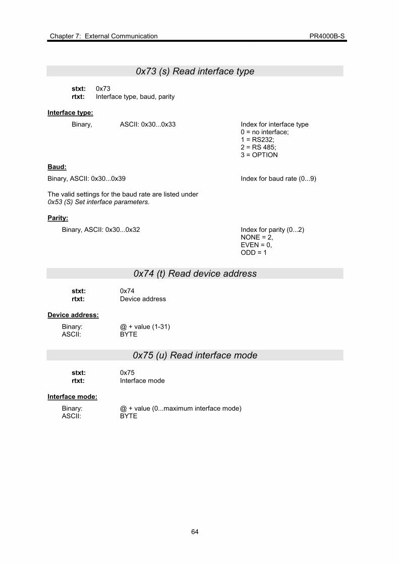
Chapter 7: External Communication PR4000B-S
64
0x73 (s) Read interface type
stxt: 0x73
rtxt: Interface type, baud, parity
Interface type:
Binary, ASCII: 0x30...0x33 Index for interface type 0 = no interface; 1 = RS232; 2 = RS 485; 3 = OPTION
Baud:
Binary, ASCII: 0x30...0x39 Index for baud rate (0...9)
The valid settings for the baud rate are listed under 0x53 (S) Set interface parameters.
Parity:
Binary, ASCII: 0x30...0x32 Index for parity (0...2) NONE = 2, EVEN = 0, ODD = 1
0x74 (t) Read device address
stxt: 0x74
rtxt: Device address
Device address:
Binary: @ + value (1-31) ASCII: BYTE
0x75 (u) Read interface mode
stxt: 0x75
rtxt: Interface mode
Interface mode:
Binary: @ + value (0...maximum interface mode) ASCII: BYTE

PR4000B-S Chapter 7: External Communication
65
0x76 (v) Read ID
stxt: 0x76
rtxt: ID string
0x7B () Lock keyboard
stxt: 0x7B
rtxt: CR (carriage return; no return)
0x7D() Unlock keyboard
stxt: 0x7D
rtxt: CR (carriage return; no return)

Chapter 7: External Communication PR4000B-S
66
This page left blank.

PR4000B-S Appendix A: Specifications
67
Appendix A: Specifications
Number of channels 1 input for flow or pressure signal
1 input for external setpoint
1 output for setpoint
1 output for signal monitoring
Accuracy 0,01% ± 1 Digit
Temperature coefficient Input:
Output:
0,1 mV / K (Ra < 1 Ω)
0,075 mV / K
Display format and resolution Two line LCD, 16 places per line , configurable:
4-digits: 0000 – 9999 (12 bit resolution)
5-digits: 00000 - 99999 (16 bit resolution)
Conversion rate Mode: EXTERN not EXTERN
Rate: 5 Hz at 16 bit 20 Hz at 12 bit
20 Hz
Signal input range (all) ±11 V, scaled in steps of 1 V
Signal output range (all) ±11 V, scaled in steps of 1 V
Relays 2 Relays, SPDT; nominal switching capacity (resistive load): 1A 30VDC, 0.5A 25VAC eff.
Interface RS232
Power output Standard:
Option:
±15 V; 1,5 A
24 V; 1 A
Input power 85 - 265 V; 47 - 63 Hz
Operation temperature 15 – 40 °C
CE yes (ref. to section 2.3 Cables)
RoHS yes
Housing ½ x 19” Rack Mounting or top on table use
241 mm x 185 mm x 88 mm (WxDxH)
Weight: 2,4 kg

Appendix A: Specifications PR4000B-S
68
This page left blank.

PR4000B-S MKS Worldwide Calibration & Service Centers
69
MKS Worldwide Calibration & Service Centers
UNITED STATES MKS Instruments, Inc.
Corporate Service Center 90 Industrial Way Wilmington, MA 01887-4610 Tel (978) 284-4000 Fax (978) 284-4303
MKS Instruments, Inc.
HPS Division,
Vacuum Components,
Valves & Gauging 5330 Sterling Drive Boulder, CO 80301 Tel (303) 449-9861 Fax (303) 449-2003
CANADA MKS Instruments, Canada Ltd. 30 Concourse Gate Nepean, Ontario, Canada K2E 7V7 (613) 723-3386 Tel (800) 267-3551 (CAN only) Fax (613) 723-9160
FRANCE MKS Instruments, France s.a. 43, Rue du Commandant Rolland B.P. 41 F-93352 Le Bourget, Cedex, France Tel 33(1)48.35.39.39 Telex 233817 F Fax 33(1)48.35.32.52
DENMARK MKS Denmark ApS Ndr. Strandvej 119G
DK-3150 Hellebæk Tel 45-44 92 92 99 Fax 45-44 92 94 99 Email: [email protected]
TAIWAN MKS Instruments, Taiwan 10F, No.93, Shoei-Yuan Street Hsinchu City 300 Taiwan, R.O.C. Tel 886-3-575 3040 Fax 886-3-575 3048
GERMANY/BENELUX MKS Instruments,
Deutschland GmbH Schatzbogen 43 D-81829 München Tel 49-89-420008-0 Fax 49-89-42-41-06 Email: [email protected]
ITALY G. Gambetti Kenologia Srl. Via A. Volta No. 2 20082 Binasco (MI), Italy Tel 39-2-90093082 Fax 39-2-905.2778
JAPAN MKS Japan, Inc. Harmonize Building 5-17-13, Narita-Higashi Suginami-Ku, Tokyo 166, Japan Tel 81-3-3398-8219 Fax 81-3-3398-8984
KOREA MKS Korea Co., Ltd. 1
st Floor DK Plaza-I
375-1 Geumgok-dong Bundang-gu,Seongnam Kyonggi-do Korea 463-805 Tel 82-31-717-9244 Fax 82-31-714-9244
UNITED KINGDOM MKS Instruments, U.K. Ltd. 1 Anchorage Court Caspian Road Altrincham, Cheshire WA14 5HH, England Tel 44-161-929-5500 Fax 44-161-929-5511
SINGAPUR MKS Instruments, Inc. BLK 4010 Techplace I #01-08/09 Ang Mo Kio Avenue 10 Singapore 569623 Tel (65) 6451 1062 Fax (65) 6451 0172
Top Related