


Languages
Pages
Legal

SINTEF ICT
Communication Systems 2015-03-10
PDSPDS
SINTEF A26762 - Unrestricted
Report
Wireless Instrumentation for Safety Critical Systems
Technology, Standards, Solutions and Future Trends
Author(s) Stig Petersen
Niels Aakvaag
PROJECT NO. 102001186
REPORT NO. SINTEF A26762
VERSION 2.0
2 of 50
Document history
VERSION DATE VERSION DESCRIPTION
1.0 2014-10-15 Draft for comments from PDS members
2.0 2015-03-10 Final version

PROJECT NO. 102001186
REPORT NO. SINTEF A26762
VERSION 2.0
3 of 50
Preface This report is a deliverable from the research project: "Tools and guidelines for integrated barrier
management and reduction of major accident risk in the petroleum industry" (2012-15). The project has
been funded by the PETROMAKS2 programme for petroleum research at the Research Council of Norway
and industry participants of PDS forum.
PDS forum is a co-operation between oil companies, engineering companies, drilling contractors,
consultants, vendors and researchers, with a special interest in safety instrumented systems in the petroleum
industry. The main objective is to maintain a professional meeting place for:
• Exchange of experience and ideas related to design and operation of Safety Instrumented Systems (SIS)
• Exchange of information on new field developments and SIS application areas
• Developing guidelines for the use of new standards on safety and control systems
• Developing methods and tools for calculating the reliability of SIS
• Exchange and use of reliability field data
Participants PDS forum
Oil companies / Operators:
A/S Norske Shell
BP Norge AS
ConocoPhillips Norge
Eni Norge AS
GDF SUEZ E&P
Odfjell Drilling & Technology
Marathon Petroleum Company (Norway) LLC
Talisman Energy Norge
Teekay Petrojarl ASA
Statoil ASA
Total E&P Norge AS
Governmental bodies (observers):
The Norwegian Maritime Directorate
The Petroleum Safety Authority Norway
Control and Safety System Vendors:
ABB AS
FMC Kongsberg Subsea AS
Honeywell AS
Kongsberg Maritime AS
Origo Solutions AS
Siemens AS
Simtronics ASA
Consultants / Engineering companies:
Aker Engineering & Technology AS
Aker Subsea AS
DNV GL Norge AS
Fabricom AS
Lilleaker Consulting AS
Safetec Nordic AS Lloyd's Register Consulting
http://www.sintef.no/PDS

PROJECT NO. 102001186
REPORT NO. SINTEF A26762
VERSION 2.0
4 of 50
Table of contents 1 Introduction .................................................................................................................................. 8
1.1 Background .................................................................................................................................... 8
1.2 Content of report ........................................................................................................................... 8
2 Wireless sensor networks .............................................................................................................. 9
2.1 History ............................................................................................................................................ 9
2.2 Technology ................................................................................................................................... 10
2.2.1 Wireless sensor node ....................................................................................................... 10
2.2.2 Network topologies ......................................................................................................... 11
2.2.3 Routing ............................................................................................................................. 12
2.2.4 Time-division multiple access and frequency-division multiple access .......................... 13
2.2.5 Security ............................................................................................................................ 14
3 International standards ............................................................................................................... 15
3.1 IEEE 802.15.4 ................................................................................................................................ 15
3.2 ZigBee / ZigBee PRO / ZigBee IP ................................................................................................... 15
3.3 6LoWPAN ..................................................................................................................................... 16
3.4 WirelessHART ............................................................................................................................... 16
3.5 ISA100.11a ................................................................................................................................... 16
3.6 WIA-PA ......................................................................................................................................... 17
3.7 WirelessHART vs ISA100.11a ....................................................................................................... 17
3.7.1 Flexibility .......................................................................................................................... 17
3.7.2 Protocol support .............................................................................................................. 18
3.7.3 Coexistence ...................................................................................................................... 18
3.7.4 Quality of Service ............................................................................................................. 19
3.7.5 Security ............................................................................................................................ 20
3.7.6 Suitability for safety applications .................................................................................... 20
4 Wireless instrumentation in the oil and gas industry .................................................................... 22
4.1 Financial and operational drivers................................................................................................. 24
4.1.1 Greenfield ........................................................................................................................ 24
4.1.2 Brownfield ....................................................................................................................... 25
4.1.3 General ............................................................................................................................ 25
4.2 Requirements ............................................................................................................................... 26
4.2.1 Technical requirements ................................................................................................... 26
4.2.2 Application specific requirements ................................................................................... 27
4.2.3 Operational considerations ............................................................................................. 28
4.3 Current status .............................................................................................................................. 30

PROJECT NO. 102001186
REPORT NO. SINTEF A26762
VERSION 2.0
5 of 50
5 Wireless instrumentation in safety critical systems....................................................................... 31
5.1 Standards ..................................................................................................................................... 31
5.1.1 General safety standards ................................................................................................. 31
5.1.2 Fieldbus communication ................................................................................................. 31
5.1.3 PROFIsafe ......................................................................................................................... 33
5.2 Important definitions ................................................................................................................... 33
5.2.1 Process Safety Time (PST) ................................................................................................ 34
5.2.2 Safety function response time (SFRT) .............................................................................. 34
5.2.3 Availability and probability of failure on demand ........................................................... 34
5.3 Availability calculation ................................................................................................................. 35
6 Comparison wired and wireless detector systems......................................................................... 37
6.1 Difference between wired and wireless detector systems ......................................................... 37
6.2 Reliability Assessment .................................................................................................................. 38
6.2.1 Example case ................................................................................................................... 38
6.2.2 Example Reliability Block Diagrams ................................................................................. 39
6.2.3 Safety Unavailability Calculation ..................................................................................... 41
7 Case Study: GasSecure ................................................................................................................. 44
7.1 Timing issues ................................................................................................................................ 44
7.2 Communication considerations ................................................................................................... 44
8 Future trends .............................................................................................................................. 46
8.1 Safety topology ............................................................................................................................ 46
8.2 Short cycle time ........................................................................................................................... 47
9 Summary and conclusions ............................................................................................................ 48
References ........................................................................................................................................... 49
PROJECT NO. 102001186
REPORT NO. SINTEF A26762
VERSION 2.0
6 of 50
Table of figures Figure 1: Wireless sensor node ........................................................................................................................ 11 Figure 2: Examples of network topologies: a) star, b) mesh, c) hybrid star-mesh .......................................... 12 Figure 3: Examples of graph routing ............................................................................................................... 12 Figure 4: TDMA timeslots, frames and superframes ...................................................................................... 13 Figure 5: Data transmission and acknowledgment within a timeslot .............................................................. 13 Figure 6: Communication Protocol Stacks ...................................................................................................... 15 Figure 7: Evolution of field device communication technologies – simplified architecture ........................... 22 Figure 8: Field instrumentation application areas and usage classes............................................................... 23 Figure 9: Commuication contribution to PFD ................................................................................................. 33 Figure 10: Availability calculation .................................................................................................................. 36 Figure 11: Wired and Wireless communication Graph ................................................................................... 38 Figure 12: Reliability block diagrams for wired detector system .................................................................... 39 Figure 13: Reliability block diagram for wireless detector system ................................................................. 40 Figure 14: GasSecure SafeWireless ................................................................................................................ 45 Figure 15: End-to-end versus proxy based safety............................................................................................ 47

PROJECT NO. 102001186
REPORT NO. SINTEF A26762
VERSION 2.0
7 of 50
List of abbreviations ACK Acknowledgment Packet
CAPEX Capital Expenditure
CCA Clear Channel Assessment
DiffServ Differentiated Services
DL Down Link (from controller to device)
DLL Data Link Layer
DSN Distributed Sensor Network
HCF HART Communication Foundation
IEC International Electrotechnical Commission
IntServ Integrated Services
ISA International Society of Automation
I/O Input/Output
LR-WPAN Low-Rate Wireless Personal Area Network
MAC Medium Access Control Layer
PCDA Process Control and Data Acquisition
PER Packet Error Rate
PHY Physical Layer
PFD Probability of Failure on Demand
PFH Probability of Failure per Hour
PRR Packet Reception Rate
PST Process Safety Time
QoS Quality of Service
RF Radio Frequency
SFF Safe Failure Fraction
SIL Safety Integrity Level
SIS Safety Instrumented System
TDMA Time Division Multiple Access
UL Up Link (from device to controller)
WSN Wireless sensor networks
6LoWPAN IPv6 over Low power Wireless Personal Area

PROJECT NO. 102001186
REPORT NO. SINTEF A26762
VERSION 2.0
8 of 50
1 Introduction
1.1 Background
The current report has been developed as part of the PETROMAKS innovation project “Tools and guidelines
for overall barrier management and reduction of major accident risk in the petroleum industry”, funded by
the Norwegian Research Council and the members of the PDS forum1. The work has mainly been carried out
by SINTEF and may therefore not express the views of all the PDS participants.
This project started autumn 2012 and will be running throughout 2015. A main goal of the project is to
develop a practical industry guideline for barrier management, covering all relevant lifecycle phases and
activities.
As part of this project, one activity is related to considering how new technology may influence the integrity
of the barriers. Wireless instrumentation used in safety critical applications has here been selected as a
specific case since recent developments are pushing the boundaries of this technology from its current usage
area in non-critical monitoring towards safety-critical applications such as fire & gas detection. The frontier
of this change is driven by the Norwegian company GasSecure which has developed the world's first
wireless hydrocarbon gas detector with SIL2 certification. The wireless gas sensor is currently undergoing
technology qualification for use within the petroleum industry.
1.2 Content of report
This report is structured as follows: Section 2 provides an introduction to wireless sensor networks (WSNs),
the underlying technology for wireless instrumentation, presenting the history and basic technology enabling
the recent development of low-power sensors and actuators with robust and resilient wireless
communication. Section 3 gives an overview of the different international standards for WSNs, with special
focus on the two specifications specifically targeting the process industries; namely WirelessHART and
ISA100.11a. Furthermore, Section 4 summarizes the current status of wireless instrumentation within the oil
and gas industry, including the financial and operational drivers for going wireless, along with the technical
requirements which must be fulfilled for a successful adoption of this new technology. Moreover, Section 5
covers the use of wireless instrumentation in safety critical systems, using the GasSecure sensor as a case.
Finally, a discussion on the consequences of using wireless instrumentation in safety critical systems can be
found in Section 6
1 PDS is a Norwegian acronym for "reliability of safety instrumented systems". For more information about PDS see:
www.sintef.no/pds

PROJECT NO. 102001186
REPORT NO. SINTEF A26762
VERSION 2.0
9 of 50
2 Wireless sensor networks
A wireless sensor network (WSN) can be defined as a collection of distributed, autonomous sensor devices
which collaborate to monitor physical or environmental phenomena such as temperature, pressure, vibration,
noise, gas and smoke. The sensor devices communicate wirelessly with each other, and a WSN typically
consists of numerous sensor devices and a network administrator which collects the sensor data from the
network.
2.1 History
Wireless sensor networks (WSNs) are a rather new technology, with its origins tracing back to the early
1980s through the Distributed Sensor Networks (DSNs) program at the Defense Advanced Research Project
Agency (DARPA) of the US Department of Defense [1]. DSNs were imagined to consist of many spatially
distributed, autonomous and low-cost sensing nodes that collaborated to gather information about their
surroundings. However, in the 1980s, the technology was not quite ready for this application. The sensors
were too large and expensive and the communication was not yet associated with wireless connectivity.
In the late 1990s, advances in computing, communication and micro-electromechanical technologies caused
a shift in DSN research, bringing it closer to achieving the original vision. The "second wave" of DSN
activities started in 1998, and it attracted large international involvement and attention. New networking
techniques and networked information processing suitable for the dynamic ad-hoc environments found in
sensor networks were the initial focus, with the goal of enabling the required complex applications to run on
resource-constrained sensors [1]. The sensors themselves also evolved with new technology, reducing both
their cost and size. In addition, advances in wireless technology enabled robust and reliable wireless
communication ideally suited for wireless distributed sensor networks. DARPA was again the pioneer,
leading the efforts of sensor network research. They initiated a research program which provided new
insights into ad-hoc networking, dynamic querying and tasking, reprogramming and multi-tasking [1]. At
the same time, IEEE started to note the potential of WSNs, and begun work on a specification for low-rate
wireless personal area networks.
The work of IEEE was finalized in 2003, when the IEEE 802.15.4 specification [2] was ratified, defining the
physical layer (PHY) and medium access control layer (MAC) for Low-Rate Wireless Personal Area
Networks (LR-WPAN). The higher layers of the protocol stack are out of scope of the specification. Offering
features such as low power, low complexity and low cost, it is ideally suited for WSN applications. With a
growing number of solutions based on the IEEE Std. 802.15.4 appearing in the years since its release, it has
become the de facto standard for WSNs. The ZigBee specification [3], originally released in 2004, was the
first full standard to appear based on the IEEE Std. 802.15.4. ZigBee defines the Network Layer and
Application Layer on top of the IEEE Std. 802.15.4 PHY and MAC.
Early research and evaluation of the IEEE Std. 802.15.4 identified several potential issues related to
information security, in addition to other minor bugs and errors. A new version of the standard was released
in 2006, IEEE Std. 802.15.4-2006 [4], which addressed these shortcomings. The original standard from 2003
is referred to as IEEE Std. 802.15.4-2003, to distinguish the two versions. Shortly after the ratification of
IEEE Std. 802.15.4-2006, the ZigBee Alliance released a new version of the ZigBee standard, ZigBee-2006
[5]. The original ZigBee standard is referred to as ZigBee-2004. ZigBee-2006 included improvements for,
among other things, addressing issues leading to scalability problems for large networks. However, it is
important to note that ZigBee-2006 was still based on IEEE Std. 802.15.4-2003, and not on the new IEEE
Std. 802.15.4-2006. Hence the security issues of IEEE Std. 802.15.4-2003 were still present in ZigBee-2006.
In 2007, the HART Communication Foundation (HCF) released the HART Field Communication Protocol
Specification, Revision 7.0 [6], which included a definition of a wireless interface to field devices, referred
to as WirelessHART. WirelessHART was the first specification to be released which was specifically
PROJECT NO. 102001186
REPORT NO. SINTEF A26762
VERSION 2.0
10 of 50
designed for process automation applications. With features such as self-healing and self-configuring multi-
hop mesh networks, WirelessHART offers a viable wireless alternative for the traditionally wired industrial
field instrumentation. WirelessHART was approved by the International Electrotechnical Commission (IEC)
as international standard IEC 62591 Ed. 1.0 for wireless communication in process automation [7] in March
2010.
The ZigBee specification was initially designed to address applications within home automation and
consumer electronics. A ZigBee network operates on the same, user defined channel throughout its entire
lifetime. This makes it susceptible both to interference from other networks operating on the same frequency
and to noise from electrical equipment and machinery in the environment. As a result, ZigBee has not been
regarded as robust enough for harsh industrial environments [8]. To combat this challenge, the ZigBee
Alliance released the ZigBee PRO specification [9] in 2007. ZigBee PRO is specifically aimed at the
industrial market, having enhanced security features and a frequency agility concept where the entire
network may change its operating channel when faced with large amounts of noise and/or interference.
Despite these innovations, ZigBee has not yet been fully adopted by the industry.
Parallel to HCF's work on WirelessHART, the International Society of Automation (ISA) initiated work on a
family of standards for wireless systems for industrial automation applications. This resulted in the
ratification of the ISA100.11a standard in September 2009 [10]. Like WirelessHART, ISA100.11a aims to
provide secure and reliable wireless communication for non-critical monitoring and control applications in
the process automation industries. A new version of the ISA100.11a was released in 2011 [11], addressing
minor faults and errors in the initial specification.
A third specification addressing wireless communication for the process automation industries, WIA-PA,
was accepted by the IEC in 2009 as IEC 62601 [12]. WIA-PA was developed by the Chinese Industrial
Wireless Alliance (CIWA) under the urgent requirements of process automation. In 2007, CIWA was
established by Shenyang Institute of Automation, along with more than 10 universities, academies, and
companies. The scope of WIA-PA is to provide a system architecture and protocol stack for use in industrial
monitoring, measurement and control applications. However, at the time of writing, no products supporting
WIA-PA are readily available on the market.
In April 2012, the IEEE 802.15.4e [13] was released as an amendment to the IEEE 802.15.4 specification. It
provides additional MAC behaviour and frame formats which allow IEEE 802.15.4 devices to support
industrial applications such as process control and factory automation. At the time of writing, no devices
supporting IEEE 802.15.4e has yet been released.
2.2 Technology
The following section presents some of the components, network topologies and communication protocol
capabilities often encountered in WSNs. This information is a restructured and modified version of
previously published material by the author [14].
2.2.1 Wireless sensor node
A wireless sensor device consists of several elements, as illustrated in Figure 1.

PROJECT NO. 102001186
REPORT NO. SINTEF A26762
VERSION 2.0
11 of 50
Power Memory / Storage
ProcessingSensing Communication
Figure 1: Wireless sensor node
The sensing unit measures a physical phenomenon (e.g. temperature or pressure), and an analogue-to-digital
converter quantifies and convers the measurement to the digital representation needed for further processing
and communication. The processing unit analyses the sensor data and encapsulates it in data packets
according to the communication protocol. The processing unit is also responsible for handling and
scheduling the communication. The communication unit provides the wireless interface, and handles
transmission and reception of data packets. It consists of an antenna and a Radio-Frequency (RF) transceiver.
The memory and storage are used for temporary and permanent storage of firmware, configuration
parameters and sensor data. The power unit is normally a battery, and it provides power to all other
components of the wireless sensor device.
One of the main challenges of WSNs is to combine long battery lifetime (i.e. low power consumption) while
simultaneously supporting complex communication protocols running on low power microcontrollers with
limited processing power and resources. The long battery lifetime requirement will normally preclude the use
of wireless actuators, and systems with wireless actuation are therefore not considered in this report.
2.2.2 Network topologies
Depending on the communication protocol and the routing capabilities of the network devices, network
topologies in a WSN may range from star to (full) mesh. In a star topology, all devices communicate with a
central coordinator, as illustrated in Figure 2a. In this setting, the sensor devices are not capable of
communicating with each other. In a mesh topology, on the other hand, all devices are capable of
communicating with all other devices within radio range, creating the topology shown in Figure 2b. It is also
possible to have a combination of a star and mesh topology, called star-mesh. In a star-mesh there is a kernel
mesh network created by router devices, and an outer network of sensors connecting to the routers. An
example of a star-mesh topology is depicted in Figure 2c.

PROJECT NO. 102001186
REPORT NO. SINTEF A26762
VERSION 2.0
12 of 50
S
R
GGateway /
Network Administrator
Router
Sensor
G
S
S
S
S
G
R
R
R
R
R
R
R
G
R
R
R
S
S
S
S
S
SS
a) b) c)
Figure 2: Examples of network topologies: a) star, b) mesh, c) hybrid star-mesh
2.2.3 Routing
Routing can be defined as the process of selecting the best communication paths in a network. In packet
switching networks encountered in WSNs, routing algorithms are responsible for directing data packets from
their source to their destination, potentially through one or more intermediate nodes. There are two different
routing algorithms which are used for routing data packets within WSN; graph and source routing.
A graph route is a list of transmission paths that connect network end points. A network may have multiple,
overlapping graphs, and a device may have multiple graphs going through it. An example of graph routing is
presented in Figure 3. Here, device A communicates with device F using Graph 1. To send a packet to device
F, device A can transmit either via device B or C, which in turn will forward the packet according to their
own graph routing configurations. The following routes from A to F are possible using Graph 1: A-B-D-F,
A-C-D-F or A-C-E-F. Similarly, to communicate with device D, device A sends packets according to Graph
2.
A
F
E
D
C
B Graph 1 (A to F)
Graph 2 (A to D)
Figure 3: Examples of graph routing
PROJECT NO. 102001186
REPORT NO. SINTEF A26762
VERSION 2.0
13 of 50
Unlike graph routes, a source route is a single directed route between a source and a destination device, and
it defines the specific path a packet must take when travelling from its source to its destination. If any of the
links in a source route fails, the packet is lost. This is not the case for graph routes, where each device has
multiple associated neighbours to which they may send packets, ensuring redundancy and enhancing
reliability compared to source routing.
The routes in a network are configured by the network manager based on periodic health reports from
devices indicating the historical quality of the wireless connectivity to their neighbours.
2.2.4 Time-division multiple access and frequency-division multiple access
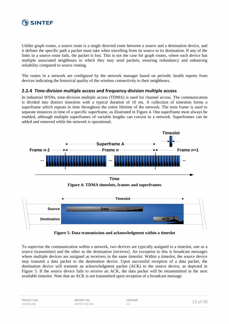
In industrial WSNs, time-division multiple access (TDMA) is used for channel access. The communication
is divided into distinct timeslots with a typical duration of 10 ms. A collection of timeslots forms a
superframe which repeats in time throughout the entire lifetime of the network. The term frame is used to
separate instances in time of a specific superframe, as illustrated in Figure 4. One superframe must always be
enabled, although multiple superframes of variable lengths can coexist in a network. Superframes can be
added and removed while the network is operational.
... ... ...
Time
Timeslot
Frame nFrame n-1 Frame n+1
Superframe A
Figure 4: TDMA timeslots, frames and superframes
Data
ACK
Timeslot
Source
Destination
Figure 5: Data transmission and acknowledgment within a timeslot
To supervise the communication within a network, two devices are typically assigned to a timeslot, one as a
source (transmitter) and the other as the destination (receiver). An exception to this is broadcast messages
where multiple devices are assigned as receivers in the same timeslot. Within a timeslot, the source device
may transmit a data packet to the destination device. Upon successful reception of a data packet, the
destination device will transmit an acknowledgment packet (ACK) to the source device, as depicted in
Figure 5. If the source device fails to receive an ACK, the data packet will be retransmitted in the next
available timeslot. Note that an ACK is not transmitted upon reception of a broadcast message.
PROJECT NO. 102001186
REPORT NO. SINTEF A26762
VERSION 2.0
14 of 50
Combined with these TDMA mechanisms, industrial WSNs also employ frequency hopping. The
communication is therefore divided into a two-dimensional matrix consisting of timeslots and frequency
channels. A link is thus specified by a superframe, a timeslot offset (relative to the first timeslot of the
superframe), and a channel offset. In consecutive superframes, a link will always have the same timeslot
offset, while the communication channel will change according to a pseudo-random hop sequence. As an
example, for a given link, communication may occur on Channel 19 in timeslot k in frame n of superframe A,
and on Channel 13 in timeslot k in frame n+1 of the same superframe. Combining TDMA and frequency
hopping in this manner allows for multiple devices to transmit data at the same time on different channels
without generating intra-network interference. Note however, that a single device may only participate in
communication on one channel (link) per timeslot.
2.2.5 Security
To ensure data confidentiality, authenticity and integrity, wireless protocols must implement sufficient
security mechanisms and algorithms. However, for WSNs with limited resources (e.g. processing power and
memory capacity), traditional security solutions can not necessarily guarantee security requirements in
industrial wireless networks [15]. The following list illustrates various security issues that wireless networks
are susceptible to:
Accidental Association: Unintentional access to a wireless network by a foreign computer or
device.
Malicious Association: Access to a wireless network is obtained by hackers in order to steal user
information, passwords or data, or to launch other attacks and install malicious software.
Identity Theft: Hacker which is able to impersonate an authorized device or user by listening to
credential traffic.
Man-in-the-Middle Attacks: Hackers gaining access to a network with Malicious Association, and
transparently monitor network traffic and/or provide false information and data to other network
users.
Denial of Service: A target device or gateway is flooded with bogus protocol messages and data in
an attempt to reduce or suspend its responsiveness and ability to perform regular functions.
Intentional jamming of a wireless communication channel falls under this category.
Network Injection: Accessing access points / gateways to introduce bogus network configuration
commands that may affect routers, switches and intelligent hubs. The network devices may crash,
shutdown, restart or even require reprogramming.
Byzantine Attack: Attack where an intruder reprograms a collection of compromised sensors,
whereby they send fictitious sensor readings to the control room.
Radio Interference: Interference from other wireless networks operating in the same frequency
bands.
Noise: Wireless networks might be negatively influenced by industrial machines and equipment
emitting electromagnetic radiation.
Solar flares: The sun occasionally ejects electrons, ions and atoms into space through large and
concentrated releases of energy called solar flares. These solar flares produce radiation across all
wavelengths of the electromagnetic spectrum, and have historically been known to disturb radio
communication and to disable energy networks when targeting the Earth.
The main tasks of the security mechanisms in WSN protocols are to provide protection against the attacks
mentioned above by ensuring secure communication between devices, and to provide message authenticity
and data confidentiality.
PROJECT NO. 102001186
REPORT NO. SINTEF A26762
VERSION 2.0
15 of 50
3 International standards
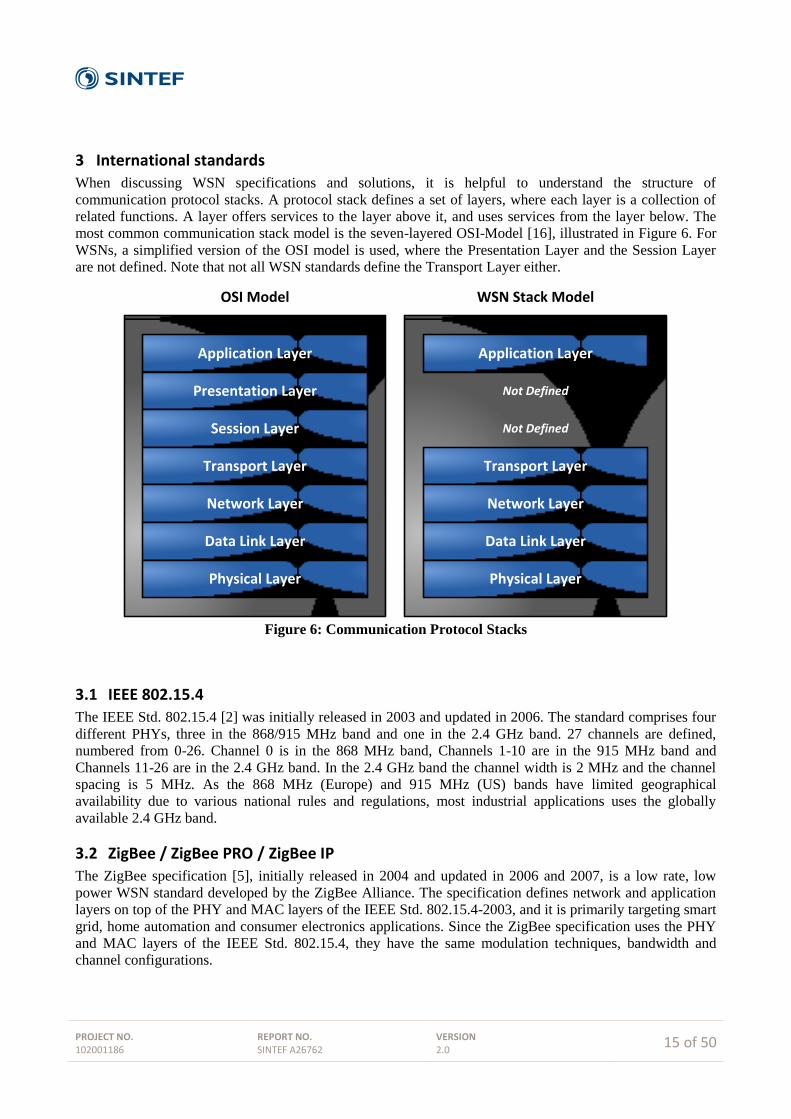
When discussing WSN specifications and solutions, it is helpful to understand the structure of
communication protocol stacks. A protocol stack defines a set of layers, where each layer is a collection of
related functions. A layer offers services to the layer above it, and uses services from the layer below. The
most common communication stack model is the seven-layered OSI-Model [16], illustrated in Figure 6. For
WSNs, a simplified version of the OSI model is used, where the Presentation Layer and the Session Layer
are not defined. Note that not all WSN standards define the Transport Layer either.
Application Layer
Presentation Layer
Session Layer
Transport Layer
Network Layer
Data Link Layer
Physical Layer
Application Layer
Transport Layer
Network Layer
Data Link Layer
Physical Layer
WSN Stack ModelOSI Model
Not Defined
Not Defined
Figure 6: Communication Protocol Stacks
3.1 IEEE 802.15.4
The IEEE Std. 802.15.4 [2] was initially released in 2003 and updated in 2006. The standard comprises four
different PHYs, three in the 868/915 MHz band and one in the 2.4 GHz band. 27 channels are defined,
numbered from 0-26. Channel 0 is in the 868 MHz band, Channels 1-10 are in the 915 MHz band and
Channels 11-26 are in the 2.4 GHz band. In the 2.4 GHz band the channel width is 2 MHz and the channel
spacing is 5 MHz. As the 868 MHz (Europe) and 915 MHz (US) bands have limited geographical
availability due to various national rules and regulations, most industrial applications uses the globally
available 2.4 GHz band.
3.2 ZigBee / ZigBee PRO / ZigBee IP
The ZigBee specification [5], initially released in 2004 and updated in 2006 and 2007, is a low rate, low
power WSN standard developed by the ZigBee Alliance. The specification defines network and application
layers on top of the PHY and MAC layers of the IEEE Std. 802.15.4-2003, and it is primarily targeting smart
grid, home automation and consumer electronics applications. Since the ZigBee specification uses the PHY
and MAC layers of the IEEE Std. 802.15.4, they have the same modulation techniques, bandwidth and
channel configurations.
PROJECT NO. 102001186
REPORT NO. SINTEF A26762
VERSION 2.0
16 of 50
A ZigBee network operates on the same, user defined channel throughout its entire lifetime. This makes it
susceptible both to interference from other networks operating on the same frequency and to noise from
other sources in the environment. As a result, ZigBee has not been regarded as robust enough for harsh
industrial environments [17]. To combat this challenge, the ZigBee Alliance released the ZigBee PRO
specification [9] in 2007 in the shape of what is defined as another feature set. ZigBee PRO is specifically
aimed at the industrial market, having enhanced security features and a frequency agility concept where the
entire network may change its operating channel when faced with large amounts of noise and/or interference.
Despite these innovations, ZigBee has not yet been fully adopted by the industry.
The ZigBee Alliance announced in April 2009 that it will incorporate standards from the Internet
Engineering Task Force (IETF) into future ZigBee releases, thereby opening up for IP-based communication
in ZigBee networks. Of special interest for the ZigBee Alliance is the 6loWPAN working group which has
created a Request for Comments (RFC4944) investigating the transmission of IPv6 packets over IEEE Std.
802.15.4 networks. This work resulted in the ratification of the ZigBee IP specification in February 2013
[18].
3.3 6LoWPAN
6LoWPAN (IPv6 over Low power Wireless Personal Area Networks) specifies the transmission of IPv6
packets on IEEE 802.15.4 networks. The 6LoWPAN overview, assumptions, problem statement and goals
are defined in RFC4919 “IPv6 over Low-Power Wireless Personal Area Networks (6LoWPANs): Overview,
Assumptions, Problem Statement, and Goals” [19], while RFC4944 “Transmission of IPv6 Packets over
IEEE 802.15.4 Networks” [20] describes the frame format for transmission of IPv6 packets and the method
of forming IPv6 link-local addresses and auto-configured addresses on IEEE 802.15.4 networks. A simple
header compression scheme for IEEE 802.15.4 mesh networks is also defined.
The 6LoWPAN definition may be used as a standalone specification for WSNs, but it is more often found as
an integrated part of the network layer of other specifications, e.g. ISA100.11a.
3.4 WirelessHART
WirelessHART is a part of the HART Field Communication Specification, Revision 7.0 [6], which was
ratified in September 2007. WirelessHART enables wireless transmission of HART messages, and was the
first standard to be released which specifically targets industrial applications. WirelessHART was approved
as IEC standard 62591 in 2010.
WirelessHART is based on the IEEE Std. 802.15.4 PHY and MAC, although the MAC has been modified to
allow for frequency hopping. Furthermore, WirelessHART only operates in the 2.4 GHz band, which allows
for global availability. TDMA with frequency hopping is used as channel access method, and with a full
mesh network topology, WirelessHART offers self-configuring and self-healing multi-hop communication.
3.5 ISA100.11a
The ISA100 standards committee of ISA aims to deliver a family of standards for wireless systems for
industrial automation. ISA100.11a [11] was the first standard to emerge, being ratified in 2009 and updated
in 2011. ISA100.11a is designed for secure and reliable wireless communication for non-critical monitoring
and control applications. Critical applications are planned to be addressed in later releases of the standard.
ISA100.11a is based on the IEEE Std. 802.15.4 PHY and MAC, but the MAC has been adopted to allow for
frequency hopping and extended security mechanisms. ISA100.11a only defines operation in the 2.4 GHz
band.
PROJECT NO. 102001186
REPORT NO. SINTEF A26762
VERSION 2.0
17 of 50
TDMA with frequency hopping is used as the channel access mechanism. ISA100.11a supports both routing
and non-routing devices, so network topologies can be either star, star-mesh or full mesh depending on the
configuration and capabilities of the devices in the network.
An ISA100.11a network is able to carry multiple fieldbus protocols, such as Foundation Fieldbus,
PROFIBUS and HART. There is also integrated support for IPv6 traffic and routing in the network layer.
3.6 WIA-PA
WIA-PA [12] is a specification for system architecture and communication protocol. It is built upon the
IEEE 802.15.4 PHY and MAC. WIA-PA was developed by the Chinese Industrial Wireless Alliance
(CIWA) under the urgent requirements of the process automation industries. WIA-PA became a Public
Available Specification (PAS) of IEC via IEC voting on October 31, 2008 with number IEC/PAS 62601.
The WIA-PA network topology is formed using cluster heads as essential device types. Each cluster head
forms a local star network. Only devices belonging to the specific cluster head can become cluster members.
The cluster members are typically field devices, i.e. sensors and actuators. Field devices are solely
input/output devices, with no routing capability. As a consequence, network topology is limited to a star-
mesh configuration. Redundancy is achieved at the cluster head, by adding a redundant cluster head. In this
manner, the local star network as a whole benefits from redundancy. However, there is no alternative route
for broken links from field device to cluster head.
At present, we are not aware of any industrial versions of wireless instrumentation employing WIA-PA.
3.7 WirelessHART vs ISA100.11a
Although WirelessHART and ISA100.11a have many more similarities than differences, there are still some
key technical properties that are different in the two standards. In the following sections, a breakdown of
some of the most prominent features that separate WirelessHART and ISA100.11a are presented.
3.7.1 Flexibility
WirelessHART and ISA100.11a are inherently different regarding the operational flexibility and
configuration possibilities that the specifications allow for. WirelessHART is a rather "simple" specification
with very few optional or configurable parameters. ISA100.11a on the other hand, is a complex and
comprehensive specification with many configurable and optional parameters found in different stack layers.
These features are both strengths and weaknesses depending on the specific needs and requirements of the
target applications and usage scenarios.
The strict and limited approach of WirelessHART ensures that practically all WirelessHART devices will
have identical behavior, regardless of design and implementation choices made by the equipment providers.
This should easily facilitate interoperability between multiple vendors, as all products adhering to the
standard should be equal. This naturally comes at the cost of a lack of possibility to adapt and tailor the
device and network behavior to specific application requirements.
The wide range of available optional and configurable parameters in ISA100.11a allows for great flexibility
for adapting network behavior to various application requirements. However, it may lead to interoperability
issues if different vendors choose to implement different features of the standard. To combat this,
ISA100.11a must define application profiles. A profile is a cross-layer specification that defines which
options are mandatory in the different protocol layers. Although profile definitions help with possible
interoperability issues, it still requires extensive compliance testing and verification to achieve full vendor
flexibility.
PROJECT NO. 102001186
REPORT NO. SINTEF A26762
VERSION 2.0
18 of 50
3.7.2 Protocol support
WirelessHART is a wireless extension of the wired HART Field Communication Protocol Specification, and
is naturally confined to using the command-based HART protocol for message exchange. All information
and data in a WirelessHART network must be transmitted in the shape of HART Commands.
The ISA100.11a application layer is object oriented, and implements tunneling features that allow devices to
encapsulate foreign protocols and transport them through the network. Although successful tunneling of
protocols depends upon how well ISA100.11a meets the technical requirements of the foreign protocol, it
still opens up the possibility of transferring a multitude of wired protocols over an ISA100.11a network.
3.7.3 Coexistence
Since WirelessHART and ISA100.11a operates in the popular 2.4 GHz band, they are likely to be subjected
to interference from other wireless networks operating in the same frequency band. In recent years, IEEE
802.11-based infrastructure has become commonplace in many process plants and facilities, and it is
expected that most wireless instrumentation deployments will share the frequency spectrum with IEEE
802.11-based access points and mobile devices. Practical experiments have shown that the performance of
IEEE Std. 802.15.4-based networks will be degraded when coexisting with IEEE 802.11 networks [21], and
since WirelessHART and ISA100.11a inherits their physical layer from IEEE Std. 802.15.4, they will be
subjected to such interference as well.
To mitigate the effects of interference, wireless protocols may employ various coexistence mechanisms. In
WirelessHART and ISA100.11a, clear channel assessment (CCA) and channel blacklisting are the weapons
of choice to combat the degrading influence from other wireless networks. However, the two standards have
chosen to implement the two features in slightly different ways. WirelessHART employs manual channel
blacklisting, where a network operator must manually configure which channels are available and which
channels are blocked. ISA100.11a has an adaptive blacklisting mechanism, where each device in a network
may autonomously blacklist channels which suffer from noise and/or interference. Furthermore, ISA100.11a
defines four different CCA modes, where modes 1-3 are defined by IEEE Std. 802.15.4:
0. No CCA: CCA is disabled, and not conducted prior to transmission.
1. Energy Above Threshold: CCA reports a busy medium upon detecting any energy above a
configurable threshold.
2. Carrier Sense Only: CCA reports a busy medium if a signal compliant with IEEE Std. 802.15.4
PHY modulation and spreading characteristics is detected.
3. Carrier Sense with Energy Above Threshold: CCA reports a busy medium using a logical
AND/OR combination of Modes 1 and 2.
WirelessHART on the other hand, has fixed its CCA mechanism to mode 2.
With the correct configuration, ISA100.11a should be somewhat better equipped to handle coexistence with
IEEE 802.11 networks. While WirelessHART only listen to activity from other IEEE Std. 802.15.4
networks, ISA100.11a will by employing either CCA modes 1 or 3 report a busy medium if any energy
above a threshold is detected. If there is activity from a nearby IEEE 802.11 access point or client, the
ISA100.11a device will back off and delay its transmission to the next available timeslot. This will naturally
result in increased latency, but no power is wasted trying to transmit a message that will most likely not be
received correctly by the destination device. In addition, the adaptive channel blacklisting mechanism of
ISA100.11a can dynamically remove this problem completely by not using channels which show high IEEE
802.11 activity.

PROJECT NO. 102001186
REPORT NO. SINTEF A26762
VERSION 2.0
19 of 50
3.7.4 Quality of Service
Although Quality of Service (QoS) is a term with various meanings and interpretations depending on the
context, it can here be accepted as a measure of the service quality that a network offers to applications
and/or users [22]. With QoS comes the ability to control the resource sharing of a network by giving
different priorities to various applications and data packets depending on their requirements. Higher
performance levels can then be provided to specific applications and data packets through a set of
measureable service parameters such as latency, jitter, packet loss, reliability and availability [23].
Support for QoS in wired networks is generally obtained by over-provisioning and/or traffic engineering
[22]. With over-provisioning, extra resources are added to the network so that it is able to provide
satisfactory services to all applications. As all users are served at the same service class, over-provisioning
may become unpredictable during peak traffic. For resource-constrained WSNs, over-provisioning is not an
ideal QoS method as the network often does not have the capacity to provide the required resources. In
traffic engineering, users and applications are assigned a different priority through a set of defined service
classes. This method is also called service differentiation, and it is a widely adopted scheme for both wired
and wireless networks to provide QoS guarantees [23]. For traditional wired computer networks there are
two main models for service differentiation; integrated services (IntServ) [24] and differentiated services
(DiffServ) [25]. The IntServ model maintains service on a per-flow basis, while the DiffServ model
maintains service on a per-packet basis. For the packet-based nature of WSNs, DiffServ is the best suited
mechanism for service differentiation [26]. In the DiffServ model, the source devices know the criticality of
the data packets is it sending, and this criticality is translated into predefined priority levels. Other devices in
the network also select the appropriate service level for data packets based on their priority.
WirelessHART defines four different priority levels on the DLL [6]:
Command (highest priority). The Command priority is used for packets containing network-related
diagnostics, configuration or control information.
Process Data. Packets containing either process data or network statistics shall be classified as
Process Data priority. Only the control of the network is more important than the delivery of sensor
data measurements from field transmitters or set-point information to actuators.
Normal. If a DLPDUs does not meet the criteria for any of the other three priority levels (Command,
Process Data or Alarm), it shall be classified with Normal priority.
Alarm (lowest priority). Packets containing only network alarm and network event information shall
have a priority of Alarm.
These priority levels are primarily used for flow control and to mitigate potential network congestion points
in the event of either a process upset or noise/interference deteriorating the RF channel(s). With the
abovementioned mechanisms, network management packets have full priority while propagated through the
network, allowing the network manager to keep the network operational. Network-induced alarms have a
restricted flow through the network, ensuring that alarm floods do not disrupt or hinder the network
operation. All other network traffic flows through the network as bandwidth and internal buffer spaces on the
devices allows. Unfortunately there is only one priority level reserved for process data, which means that all
sensors and/or actuators in a WirelessHART network share the same priority level, regardless of the
requirements and criticality of the application they are serving.
ISA100.11a uses contracts to define the setup and requirement of communication between two devices in a
network. A contract is an agreement between the system manger and a device in the network that involves
the allocation of network resources by the system manager to support the communication requirements of the
device. All contracts are unidirectional, and they are established by the system manager upon reception of a
contract request. ISA100.11a supports two priority levels, contract priority and message priority. The

PROJECT NO. 102001186
REPORT NO. SINTEF A26762
VERSION 2.0
20 of 50
contract priority is the base priority for all messages sent using a specific contract. Four contract priorities
are supported [11]:
Network control (highest priority): May be used for critical management of the network by the
system manager.
Real time buffer: May be used for periodic communications in which the message buffer is
overwritten whenever a newer message is generated.
Real time sequential: May be used for applications such as voice or video that need sequential
delivery of messages.
Best effort queued (lowest priority): May be used for client-server communications.
The message priority establishes priority within a contract using two messages priorities: high and low. The
contract priority is specified by the application, during contract establishment time, in its contract request. It
may be used by the system manager to establish preferred routes for high priority contracts and for load
balancing the network. The combined contract and message priority is used to resolve contention for scarce
resources when these messages are forwarded through the network.
3.7.5 Security
Both WirelessHART and ISA100.11a rely on a centralized security manager for the authentication of new
devices, and the generation and management of security keys throughout the lifetime of the network. This
means that the loss of the security manager will cause the loss of security mechanisms in the network. New
releases of WirelessHART and ISA100.11a networks are combating this issue by offering redundant network
and security manager solutions with automatic and transparent handover from the primary to the secondary
system in case of failure.
In WirelessHART, all security features are mandatory, while ISA100.11a defines many security mechanisms
as optional. Considering that security algorithms require additional processing time, memory, and power,
making them mandatory means that devices that may not require strict security policies cannot disable them
to achieve benefits such as extended battery life. On the other hand, the ISA100.11a concept of having
optional security features may be a security threat in itself, and also an issue when it comes to
interoperability. Vendors might not choose to implement the full security suite, and different vendors might
choose to implement different parts of the optional security features.
3.7.6 Suitability for safety applications
In safety applications, reliability and timeliness are the main requirements for the communication between
sensors and the safety system. As opposed to control-loops, rapid update rates are normally not required, but
safety communication must have mechanisms which ensure that data packets arrive within a specific
deadline. For most safety systems, a query-based data delivery model is used where the safety controller
periodically requests data from the sensors.
Safety systems in the process industries are subject to comply with a certain Safety Integrity Levels (SIL).
The standard IEC 61508 [27] defines SIL from a set of requirements that both accomplish hardware safety
integrity and system safety integrity. There are four SIL levels (1-4), where SIL 4 is defined as the most
dependable and SIL 1 as the least. Neither WirelessHART nor ISA100.11a directly supports the necessary
certified SIL safety mechanisms as an integrated part of their specifications. A workaround for this is to use
an already established and certified end-to-end communication protocol, such as PROFIsafe [28], which is
designed to be implemented on top of the PROFINet fieldbus [29].
PROJECT NO. 102001186
REPORT NO. SINTEF A26762
VERSION 2.0
21 of 50
The recent development of the world's first wireless hydrocarbon gas detection system has proven that it is
possible to achieve SIL2 end-to-end communication between a safety controller and a wireless sensor by
tunnelling PROFIsafe over ISA100.11a [30]. For WirelessHART on the other hand, limitations in currently
available HART commands at the application layer, makes it impossible to implement the tunnelling
mechanisms needed for full PROFIsafe support. PROFIsafe over WirelessHART will thus not be available
before a potential modification and new release of the HART Field Communication Protocol Specification is
available.
A more in-depth analysis of the suitability of WirelessHART and ISA100.11a for safety applications is
presented in chapter 5.
PROJECT NO. 102001186
REPORT NO. SINTEF A26762
VERSION 2.0
22 of 50
4 Wireless instrumentation in the oil and gas industry
Wireless instrumentation is defined as the merger of wireless sensor network (WSN) technologies with
process automation disciplines. A wireless field instrument is typically a traditional, formerly wired, sensor
or actuator equipped with an additional radio transmitter, antenna and power supply (battery). The
instrument parts (i.e. sensor or actuator elements) are the same as for a wired instrument, and they have the
same measurement performance characteristics and accuracies.
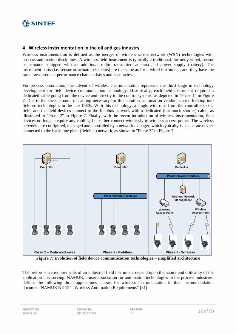
For process automation, the advent of wireless instrumentation represents the third stage in technology
development for field device communication technology. Historically, each field instrument required a
dedicated cable going from the device and directly to the control systems, as depicted in "Phase 1" in Figure
7. Due to the sheer amount of cabling necessary for this solution, automation vendors started looking into
fieldbus technologies in the late 1980s. With this technology, a single wire runs from the controller to the
field, and the field devices connect to the fieldbus network with a dedicated (but much shorter) cable, as
illustrated in "Phase 2" in Figure 7. Finally, with the recent introduction of wireless instrumentation, field
devices no longer require any cabling, but rather connect wirelessly to wireless access points. The wireless
networks are configured, managed and controlled by a network manager, which typically is a separate device
connected to the backbone plant (fieldbus) network, as shown in "Phase 3" in Figure 7.
Phase 3 - WirelessPhase 2 - FieldbusPhase 1 – Dedicated wires
Controller Controller Controller
Wireless Network
Management
Wireless
Access Point
Wireless
Access Point
Figure 7: Evolution of field device communication technologies – simplified architecture
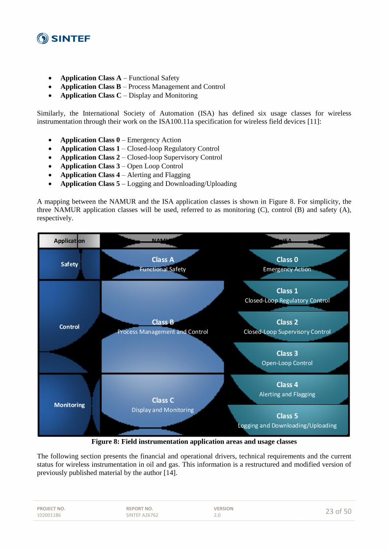
The performance requirements of an industrial field instrument depend upon the nature and criticality of the
application it is serving. NAMUR, a user association for automation technologies in the process industries,
defines the following three applications classes for wireless instrumentation in their recommendation
document NAMUR NE 124 "Wireless Automation Requirements" [31]:
PROJECT NO. 102001186
REPORT NO. SINTEF A26762
VERSION 2.0
23 of 50
Application Class A – Functional Safety
Application Class B – Process Management and Control
Application Class C – Display and Monitoring
Similarly, the International Society of Automation (ISA) has defined six usage classes for wireless
instrumentation through their work on the ISA100.11a specification for wireless field devices [11]:
Application Class 0 – Emergency Action
Application Class 1 – Closed-loop Regulatory Control
Application Class 2 – Closed-loop Supervisory Control
Application Class 3 – Open Loop Control
Application Class 4 – Alerting and Flagging
Application Class 5 – Logging and Downloading/Uploading
A mapping between the NAMUR and the ISA application classes is shown in Figure 8. For simplicity, the
three NAMUR application classes will be used, referred to as monitoring (C), control (B) and safety (A),
respectively.
Class 0Emergency Action
Monitoring
Control
Safety
Class 1Closed-Loop Regulatory Control
Class 2Closed-Loop Supervisory Control
Class 3Open-Loop Control
Class 4Alerting and Flagging
Class 5Logging and Downloading/Uploading
Application ISANAMUR
Class AFunctional Safety
Class BProcess Management and Control
Class CDisplay and Monitoring
Figure 8: Field instrumentation application areas and usage classes
The following section presents the financial and operational drivers, technical requirements and the current
status for wireless instrumentation in oil and gas. This information is a restructured and modified version of
previously published material by the author [14].

PROJECT NO. 102001186
REPORT NO. SINTEF A26762
VERSION 2.0
24 of 50
4.1 Financial and operational drivers
The financial and operational drivers for wireless instrumentation in the oil and gas industry can be divided
into three categories; Greenfield (new facilities), Brownfield (existing facilities) and general.
4.1.1 Greenfield
As the discovery rate of larger oil fields is decreasing rapidly, future developments (Greenfield) need to
focus more and more on cost-effective solutions for marginal fields. To achieve an acceptable break-even,
many of these production facilities are planned as limited-, or even unmanned facilities. At a marginal field,
the production process is more often subject to changes compared to a larger field. A change in the
production process may require a change in instrumentation. The flexibility that is provided by wireless
instrumentation opens for the planning of dynamic production environments to a much larger degree
compared to traditional plant designs with wired instruments.
For Greenfield projects in general, CAPEX (capital expenditure) related to engineering, commissioning and
installation represent the major cost savings for wireless instrumentation through the elimination of local
field cable and associated field-run cable trays to local remote-I/O cabinets.
The number of instruments in a wireless network installed in a traditional offshore platform environment will
be influenced both by the layout of the facility and by the limitation of the technology. A wireless network
comprises field instruments (wireless sensors) and a reception point, commonly referred to as the wireless
gateway. The number of wireless instruments per gateway will depend on:
Update rate per wireless instrument; a fast update rate will occupy more time slots in the fixed-
length superframe than a slow update rate (see section 2.2), thus reducing the maximum number of
devices in the network.
The physical environment. For example, radio transmission is not possible between neighbouring
spaces that are shielded from each other by metal partitions, since a metal partition is an effective RF
shield.
It is possible to calculate estimated cost savings for wireless instrumentation networks, assuming a network
with e.g. 30 wireless instruments per gateway. The cost estimate includes the following parameters:
Cost savings related to cable and cable tray installations
Reduced costs due to no need for circuit drawings
Added cost for the wireless instrument due to an estimated 30% higher purchase cost compared to
the equivalent wired version
Gateway cost (shared by 30 wireless instruments)
By using typical vendor prices, and cost estimates on work load and hours from former Statoil projects, the
total cost saving per wireless instrument is approximately USD 3,300. Note that the cost saving per
instrument will increase with an increased number of wireless sensors per gateway, and vice versa [14].
For offshore facilities, weight savings is also a preferred advantage introduced by wireless instrumentation.
In addition to the facilities’ total weight, logistics and freight weights from onshore supply bases to offshore
facilities also affect the weight budget. The main contributions to weight savings for wireless instrumentation
comes from the elimination of cabling, cable trays, junction boxes, I/O cabinets and similar. A weight budget
estimate carried out by Statoil takes into account the following parameters:
PROJECT NO. 102001186
REPORT NO. SINTEF A26762
VERSION 2.0
25 of 50
Weight savings related to cable and cable trays, including supporting installations
Added weight from cabling, including trays and support for the wireless gateway
Added weight from wireless gateway
For Greenfield projects, calculations performed by Statoil show that the net weight saving per wireless
instrument is approximately 31 kg. The base for the calculations is again a wireless network with 30 wireless
instruments per gateway, and the weight saving per instrument will increase with an increased number of
wireless sensors per gateway, and vice versa.
4.1.2 Brownfield
In modification projects (Brownfield), it is assumed that cost and weight savings will be even higher than for
Greenfield. The added value from wireless instrumentation in Brownfield is due to:
Existing installations do not have the remote I/O architecture required to support additional
instrumentation. For this reason, installing supplementary wired instrumentation will require pulling
cables all the way from instrument to local equipment room
Pulling cables to local equipment room will in most cases require junction boxes on the way
Terminating the signal in local equipment room will require marshalling cabinets
The savings will vary among installations as a result of:
Distance between instrument and local equipment room
Spare capacity on cable trays
Spare capacity in junction boxes
Spare I/O channels
Size of planned wireless network, i.e. more instruments per gateway equals a lower cost per
instrument
For typical monitoring instruments (pressure, temperature, etc), cost savings are estimated to 2-3 times
higher compared to Greenfield projects with remote I/O, i.e. in the area of USD 6,600 to USD 9,900. For
vibration monitoring instruments, the cost savings are estimated to be somewhat higher.
4.1.3 General
In the above sections on Greenfield and Brownfield considerations, cost savings and weight savings have
been presented as the major drivers for implementing wireless instrumentation in the oil & gas industry.
However, there are additional drivers and motivational factors for going wireless, including:
Simplified upgrades and/or replacements due to reduction of time and complexity
Easy installation of temporary instrumentation, e.g. added monitoring capability in a part of the
process plant during special conditions
A wireless infrastructure allows for mobile instrumentation, for example portable field instruments
used during maintenance and modification tasks
Practical experience shows that for existing installations (Brownfield), the process of taking the initial
decision to install wireless instrumentation is subject to most assessments and discussions, and thus becomes
the most time consuming part of the process. Once the wireless instrumentation infrastructure is established,
new application areas and new field instruments rapidly emerge. A good example is Statoil’s Gullfaks field,
which back in 2007 started with one wireless sensor network serving 13 wireless temperature transmitters at
PROJECT NO. 102001186
REPORT NO. SINTEF A26762
VERSION 2.0
26 of 50
Gullfaks A. Today, the three Gullfaks facilities (A, B and C) have several wireless sensor networks serving
about 140 temperature and pressure transmitters, used for different monitoring applications (Class C).To
date, the networks have been performing adequately, providing the required sensor data in a reliable and
timely manner.
New development projects should plan with a wireless strategy in mind. Even though development projects
traditionally rely on well proven technology, this is also the case for instrumentation. However, the time has
definitely come to offer wireless technology the attention it deserves in the planning process. Although at the
planning stage all application areas or possibilities of wireless technology may not be obvious, designing the
plant with a strategy for wireless instrumentation and also preparing for a wireless infrastructure should be a
part of the design specification.
4.2 Requirements
The requirements for wireless instrumentation in the oil & gas industry can be divided into two categories;
technical requirements which are not application depended and apply to all wireless instrumentation, and
application specific requirements related to instrument usage classes. In addition there are general
operational considerations which must be addressed in order to achieve successful deployment of wireless
instrumentation in process plants.
4.2.1 Technical requirements
The following technical requirements for wireless instrumentation have been established by the oil and gas
industry, regardless of application class.
Unlicensed frequency bands
The radio spectrum is a limited natural resource, and as a result, the frequency band usage is strongly
regulated by the authorities. Most frequencies are licensed for specific applications and technologies, but
there are still some portions of the frequency bands which are open for free, unlicensed operation. These
bands are called ISM-bands (industrial, scientific and medical), and their availability varies by country and
region.
The most common ISM-band for short-range wireless communication is the 2.4 GHz band, which has the
benefit of being globally available.
Friendly coexistence with other wireless solutions
Wireless technologies are becoming more commonplace, even in industrial facilities. When two or more
wireless systems are deployed within radio range of each other, it is imperative that they are capable of
friendly coexistence. This means that neither system should suffer critical performance degradation during
operation.
Most wireless instrumentation solutions operate in the globally available 2.4 GHz band, which is also
occupied by the popular IEEE 802.11-based wireless local area networks (also known as Wi-Fi). The
widespread adoption of Wi-Fi has also reached the process industries, and it is expected that most wireless
instrumentation deployments will be in an area that is under influence from a nearby Wi-Fi access point.
Standardized and open solutions
Standardized and open communication protocols provide the industry with the flexibility and freedom to
choose between multiple vendors while having guaranteed interoperability. Standardized solutions also have
the added benefit of longer lifespans for component availability and support compared to proprietary
solutions, while at the same time preventing commitment to a single supplier.

PROJECT NO. 102001186
REPORT NO. SINTEF A26762
VERSION 2.0
27 of 50
Protection from cyber-attacks and threats
Wireless instruments transmit information over the air, which make them more vulnerable to eavesdropping
and other security breaches than their wired counterparts. To ensure data confidentiality, authenticity and
integrity, the wireless protocols must implement sufficient security mechanisms and algorithms to prevent
unintentional and malicious threats and attacks (see section 2.2.5 for more information on security).
Quantifiable network performance
The performance of wireless communication networks is susceptible to environmental changes in the
deployment area. Factors such as mobile equipment and personnel, electromagnetic noise and interference
from machinery, interference from other wireless systems, variations in temperature and humidity, and
weather (e.g. rain and snow) might influence the quality of a wireless communication link. It is therefore
important to be able to quantify within reasonable accuracy the expected and operational performance with
regards to availability and reliability of wireless solutions.
Specific requirements for the network performance parameters will vary according to the usage class.
Typical measurement parameters for quantifying the network performance are:
Latency. Latency should be defined as the end to end delay of data delivery, measured from the
sampling instant of a sensor till the sensor data is received at the data consumer (typically the control
room software). As most wireless instrumentation deployments have a wired connection from the
wireless gateway to the control room, the latency should include the whole communication chain,
i.e. starting from the originating sensor, through the wireless network and to the gateway, and over
the wired fieldbus to the final application. The latency from the wireless transmission will as such
only be a part of the total latency, although it should be possible to measure and report the specific
latency for each data packet traversing the wireless network.
Packet Error Rate (PER). The packet error rate (PER) is the percentage of packages which are lost
in transmission. PER is registered by the transmitting device when an ACK is not received from the
destination device, and it is measured on a link to link basis. PER is used as a quality measure for
links, and is the foundation for the self-healing and self-configuring capabilities of WSNs. Links
which suffer from high PER over a period of time will be reported as bad, and the routing protocols
will be updated in order to reduce their usage.
Packet Reception Rate (PRR). The packet reception rate (PRR) is defined as the percentage of data
packets which reach their final destination in a timely manner, i.e. within a certain time deadline. It
is worth noting that in WSNs it is possible to have a high PRR even in networks which suffer from
high PER, due to the fact that lost packets are retransmitted, possible over different routes. (see
Chapter 5.4)
4.2.2 Application specific requirements
The following requirements apply only to the specific application class for wireless instrumentation.
Monitoring applications (Class C)
Monitoring applications includes tasks which, by definition, are not of any immediate operational
consequence, nor affect plant safety in any regard. As a result, the network performance requirements for
wireless instrumentation applied in monitoring applications are quite relaxed. However, it is still of interest
to maintain a certain level of service quality in order for the application to be of any benefit. To maintain a
proper data update and application value, it should be expected that wireless instrumentation for monitoring
applications to have a high PRR (~99%), and a latency level which is not too high compared to the
measurement rate.

PROJECT NO. 102001186
REPORT NO. SINTEF A26762
VERSION 2.0
28 of 50
Control applications (Class B)
In control applications, the main challenge is to be able to provide sensor and actuator data in a timely and
regular manner. Latency should be kept as low as possible, and it must naturally be relative to the sampling
rate of the process. In addition to low latency, it is of high importance to have low jitter (defined as the
variance of the latency of consecutive data updates), as it is challenging to design control algorithms which
are capable of handling aperiodic reception of sensor data. To achieve low latency and jitter, it is
recommended to implement proper fieldbus interfaces (e.g. PROFIBUS or Foundation Fieldbus) on the
wired side of the wireless gateway and on the instrumentation backbone networks.
Another advantage, if not a strict requirement, for control applications is to have a common timing domain
for all components in the system. This means that the clocks of wireless sensors and actuators and the
wireless gateway should be synchronized with the clocks of the controllers and control system. Propagating
time information through the wireless network should be possible, as a clock accuracy of 1 ms is already
required for all wireless devices in order for the TDMA timeslot structure to work properly according to
todays' wireless standards.
Safety applications (Class A)
In safety applications, the main challenges are found in reliability and timeliness for the communication. As
opposed to for example control loops, rapid update rates (in the millisecond range) are normally not the
important issue. On the contrary, safety applications require mechanisms that ensure that data packets arrive
at the designated destination within a well-defined timeout window. For most safety systems continuous
monitoring is required, and in case a sensor reading is above a specified threshold value, a well-defined
response to the control system is required.
Safety instrumented systems in the oil & gas industry are subject to comply with a certain Safety Integrity
Levels (SIL). The standard IEC 61508 [33] defines SIL from a set of requirements that both accomplish
hardware safety integrity and system safety integrity. There are four SIL levels (1-4), where SIL 4 is defined
as the most dependable and SIL 1 as the least.
4.2.3 Operational considerations
For a successful deployment of wireless instrumentation, the following operational considerations must be
adequately addressed:
Battery lifetime
The elimination of cables is one of the main benefits and motivational drivers for wireless instrumentation.
Unfortunately, this means that the power needed to operate the wireless instruments must originate from a
local power source, typically a battery. It is also possible for the devices to harvest and scavenge energy from
the environment (e.g. through harvesting energy from the sun, vibration, temperature fluctuations and so on),
but currently available energy harvesting technologies have some limitations in the amount of energy it is
possible to generate.
The battery lifetime of a wireless instrument depends on the update rate of the sensor measurements. With
current solutions, a battery lifetime of 5-10 years can be achieved with update rates at 15 seconds or more.
For the fastest applications with an update rate of 1 second, the battery lifetime is somewhere between 6
months to 1 year, depending on the manufacturer. The battery lifetime is also affected by ambient weather
conditions, where low temperatures decreases battery capacity while higher temperatures increases the
capacity. The standard rating for battery capacity is at room temperature, defined as 25°C / 77°F.

PROJECT NO. 102001186
REPORT NO. SINTEF A26762
VERSION 2.0
29 of 50
The battery packs for wireless instrumentation are designed to be replaceable in the field, and have the same
EX-classification as the wireless instruments.
Redundancy
The wireless gateway represents a single point of failure. For most industrial applications, it is preferable
with redundant gateway systems providing automatic fail-over in the case of loss of one gateway. For control
and safety systems this should be an absolute requirement. It is preferable with gateway systems that
integrate directly with the PCDA (Process Control and Data Acquisition) system, for example in the form of
CPU modules that fits directly into the controller node. This way, only the radio module or antenna needs to
be installed in the process area. For hazardous environments, such architecture is preferred because it
simplifies ATEX issues for the wireless gateway. “All-in-one” gateway solutions has proved to be difficult
to design in intrinsic safe versions according to ATEX zone 1 requirements, due to inherent power
requirements for the CPU boards.
Operation in harsh and hazardous environments
Process plants are found in practically any environment and climate in the world, and the deployment
condition for wireless instruments may range from cold winter with snow and ice in arctic regions, to
extreme heat and sand in desert regions. The electronic and mechanical components must be designed and
encapsulated in order to withstand any external influences, and the wireless communication link must also be
able to handle these conditions. Furthermore, most process plants are classified as hazardous areas, where
stringent requirements apply to any installed equipment. Regulations and classifications for equipment
operating in hazardous areas vary from country to country. In the European Union it is governed by directive
94/9/EC [32] and for the US and Canada it follows the North American Hazardous Locations Installation
Codes. The hazardous locations certification documents and standards from the International
Electrotechnical Commission (IEC) are used by most other countries in the world.
Commissioning, engineering, provisioning and integration
Wireless instrumentation for industrial applications should provide identical electric and mechanical
interfaces as wired systems. As wireless instrumentation is expected to live side by side to wired systems in
the foreseeable future, it is imperative that the integration to existing networks, fieldbuses and back-end
systems is made as smooth as possible. The mechanical quality and expected lifetime of a wireless
instrument should be equivalent to a wired instrument, including the radio communication part of the device.
Mounting brackets and other mechanical details, as well as the quality of these, should also be identical to
those of wired instruments. Wireless gateways should be mechanically designed to sustain harsh
environments, while providing easy mounting and termination of field cables.
Wireless instruments need to be configured before they can join a wireless network. The process of
configuring new devices to join an existing network, commonly referred to as provisioning, should be
implemented as straight forward as possible in order to ensure this becomes a simple task in the field.
Work processes
Meeting the technical requirements is just one step towards a successful implementation of wireless
instrumentation. It is important not to overlook the human factor when adoption new technology, and it is
imperative to study and plan for how new solutions can be incorporated into existing work processes.
Although wireless instrumentation will eliminate the need for manual labour in relation to maintenance,
inspection and operation (e.g. physical inspections and manual data acquisition), the introduction of new
work processes is unavoidable. This includes new procedures and tasks for installation, remote
configuration, battery replacements and maintenance of wireless transducers and communication systems. A
key requirement in this regard is to hide the complex radio-frequency issues related to security, infrastructure

PROJECT NO. 102001186
REPORT NO. SINTEF A26762
VERSION 2.0
30 of 50
reliability and wireless transmission issues (e.g. noise and interference) from the field worker. Wireless
instrumentation systems are designed to be self-configuring and self-healing to adapt dynamically to
frequency disturbances, and they incorporate an easily implementable but fully functional security suite, so
that they reduce the complexity of work.
4.3 Current status
To date, most wireless instrumentation deployments in the oil & gas industry have been limited to non-
critical monitoring applications. Previous research and experience from theoretical studies, laboratory
experiments and pilot installations on offshore installations has shown that wireless instrumentation is fully
capable of providing sufficient operational performance for non-critical monitoring applications [34][35]. As
a result, several oil & gas producing companies has approved wireless instrumentation for non-critical
monitoring purposes, and, within these limitations, wireless instrumentation is ready for adoption at scale in
the industry. Wireless instrumentation technology is still not considered mature enough for other application
areas, as the currently available solutions are not able to fulfil the more stringent requirements for control
and safety applications. However, recent research and development of a SIL 2 compliant wireless gas
detection system might lead to the approval of wireless instruments for safety applications in the near future
[30]. Wireless instrumentation in safety critical systems will be addressed in more detail in the next chapter.

PROJECT NO. 102001186
REPORT NO. SINTEF A26762
VERSION 2.0
31 of 50
5 Wireless instrumentation in safety critical systems
Safety instrumentation falls into one of two operation modes: continuous and low demand mode.
Continuous, or high demand mode, devices are evaluated according to their Probability of Failure per Hour
(PFH), i.e. what is the probability of failure in one hour of operation. The low demand mode devices are
evaluated according to their Probability of Failure on Demand (PFD).
In the discussion below, both cases are considered. Arguments can be made for either, depending on the type
of equipment and the way it is used. The sensor itself can normally be assumed to be low demand mode if it
is not an active part of a control loop and that its safe operation is called upon only occasionally. However, if
the wireless communication fails for a prolonged period (exceeding the process safety time) the device will
not be able to perform its safety function. A communication failure is therefore a "dangerous detected"
failure in that any missing packets will be discovered immediately. In the below calculations we consider the
contribution to the PFD/PFH of the communication system as a function of repeated packet failure.
It is worth noting that the PROFIsafe standard explicitly allows for wireless communication, detailing the
use of WLAN or Bluetooth as carriers. These standards are therefore considered sufficiently robust and
secure to provide functional safety over a wireless link. The argument used to support this claim is that
PROFIBUS can be used with bit error rates (not packet error rates) up to 10-2
, and that this is easily
achievable over wireless. The relevant part of the PROFIsafe specification also notes that the primary
challenge of wireless in not achieving the required safety, but in the system availability. WirelessHART and
ISA100.11a contain similar security mechanisms as WLAN and Bluetooth and they operate in the same
frequency band. In addition they are designed for low power consumption, making them better suited for
battery operation.
5.1 Standards
5.1.1 General safety standards
The fundamental standards for safety instrumented systems in the process industry are IEC 61508 [36] and
IEC 61511 [37]. The former handles all applications where electronic or programmable electronic devices
are used to perform safety functions. It is a generic specification and is independent of the final application.
It defines the necessary documentation that needs to be developed and maintained as well as the probabilities
of failure (PFD or PFH) that need to be achieved to obtain a certain SIL (safety integrity level) level. Its
various parts cover hardware, software, and guidelines on how the development shall be performed. It is
aimed at manufacturers of equipment.
The latter standard is aimed specifically at the process industry. It takes a more system oriented approach and
considers the inclusion of all sorts of equipment (including "proven-in-use") into an over-all view of the
process. It is aimed more at integrators and process operators.
5.1.2 Fieldbus communication
The fieldbus communication aspects of safety instrumented systems (SIS) are detailed in IEC61784-3 [38].
This standard considers the communication from the sensor, through the controller, to the actuator. In
particular it lists the possible causes of communication error and the required mechanisms that need to be put
in place in order to mitigate them. This is summarised in the below table:
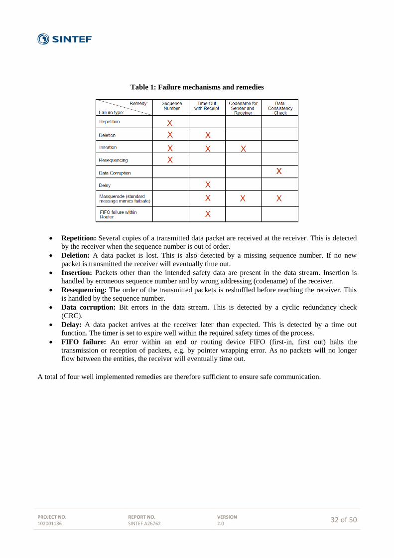
PROJECT NO. 102001186
REPORT NO. SINTEF A26762
VERSION 2.0
32 of 50
Table 1: Failure mechanisms and remedies
Repetition: Several copies of a transmitted data packet are received at the receiver. This is detected
by the receiver when the sequence number is out of order.
Deletion: A data packet is lost. This is also detected by a missing sequence number. If no new
packet is transmitted the receiver will eventually time out.
Insertion: Packets other than the intended safety data are present in the data stream. Insertion is
handled by erroneous sequence number and by wrong addressing (codename) of the receiver.
Resequencing: The order of the transmitted packets is reshuffled before reaching the receiver. This
is handled by the sequence number.
Data corruption: Bit errors in the data stream. This is detected by a cyclic redundancy check
(CRC).
Delay: A data packet arrives at the receiver later than expected. This is detected by a time out
function. The timer is set to expire well within the required safety times of the process.
FIFO failure: An error within an end or routing device FIFO (first-in, first out) halts the
transmission or reception of packets, e.g. by pointer wrapping error. As no packets will no longer
flow between the entities, the receiver will eventually time out.
A total of four well implemented remedies are therefore sufficient to ensure safe communication.

PROJECT NO. 102001186
REPORT NO. SINTEF A26762
VERSION 2.0
33 of 50
Figure 9: Commuication contribution to safety unavilability
The standard also specifies that the communication channels should contribute to no more than 1 % of the
acceptable PFD/PFH each. This is shown in Figure 9. Any communication system possessing the above
characteristics can, in theory at least, be used for a SIS.
5.1.3 PROFIsafe
IEC61784-3-3 [39] defines PROFIsafe as one of several safety protocols that can be used to achieve
functional safety. PROFIsafe has implemented the four safety measures described in the above section. An
implementation using PROFIsafe therefore facilitates the SIL certification of a product or system.
The implementation of the four remedies is specific to PROFIsafe.
Sequence number: The sequence number is an eight bit unsigned integer that increases
monotonically and wraps at 255. It is not sent over the air, but used as a basis for calculating the
CRC. This maintains the functionality, reduces overhead, and makes masquerading more difficult.
Timeout: Every entity in a transmitter-receiver relationship keeps a local version of the timer. It is
cleared whenever a safe packet is transmitted and is incremented with a 1ms time resolution. It is
represented in a 16 bit unsigned number, implying that the maximum timeout limit the protocol
supports is approximately 65 seconds.
Codename: The codename is chosen by the user as a 16 bit identifier.
CRC: The CRC is designed to provide sufficient protection against bit errors. There are two
versions: 24 bit and 32 bit. The shorter is used with short data packets (not longer than 12 bytes).
Longer packets need the increased protection given by the long CRC.
It is worth keeping in mind that a wireless communication system will have additional checks such as CRC
and codename. The remedies put in place by the safety layer thus come in addition to those already
implemented in the radio stack.
5.2 Important definitions
Below are a set of definitions from different standards needed to calculate the availability of safety systems
using wireless communication.
PROJECT NO. 102001186
REPORT NO. SINTEF A26762
VERSION 2.0
34 of 50
5.2.1 Process Safety Time (PST)
The process safety time (PST) is defined in [36] as the:
Period of time between a failure, that has the potential to give rise to a hazardous event occurring at the
EUC (Equipment Under Control) or EUC control system, and the time by which action has to be
completed in the EUC to prevent the hazardous event from occurring.
The PST represents the absolute maximum time delay for suitable safety action. The PST is highly
application dependent, and it will naturally affect the acceptable latency in the communication chain. It will
often be established based on what is possible with the available equipment, and will include the detection
time (DT), the Time to Safe State (TSS), and a margin to compensate for additional delays.
Examples of PSTs include:
Gas sensors: 60 seconds (IEC 60079-29-1)
Boiler control: 5-10 seconds (typically, API Recommended Practice 538)
Pressure valves: 5 seconds or lower (typically, application dependent)
5.2.2 Safety function response time (SFRT)
An additional parameter of interest is the safety function response time (SFRT). It is defined in [38] as:
Worst case elapsed time following an actuation of a safety sensor connected to a fieldbus, before the
corresponding safe state of its safety actuator(s) is achieved in the presence of errors or failures in the safety
function channel
This definition explicitly allows for problems occurring in the communication medium. In the PROFIsafe
standard [39] PST and SFRT are closely linked. Clearly the PST includes also the time taken to detect the
failure, a figure that is not implied by the SFRT. Contrary to the PST, the SFRT is often quoted by the
manufacturers of equipment as its worst case response time whereas the PST is application dependent.
5.2.3 Availability and probability of failure on demand
Availability can be defined [36] as follows:
Availability 1:
Probability for an automated system that for a given time there are no unsatisfactory system conditions
such as loss of production.
In IEC 61508 availability is not explicitly defined, but referred to as being the probability of an item
functioning at a given instant (e.g. IEC 61508-4, section 3.4.6). With reference to the new ISO-TR 12489 the
term is defined as:
Availability 2:
Probability for an item to be in a state to perform as required at a given instant
The TR points out that for non-repairable systems reliability and availability becomes identical. It should be
noted that in PDS the (safety) availability is the major concern, i.e. what is the probability that the
component or the system functions upon a demand.
PROJECT NO. 102001186
REPORT NO. SINTEF A26762
VERSION 2.0
35 of 50
The probability of failure on demand (PFD) for low demand systems is linked to the availability. In [36] it is
defined as:
Safety unavailability of an E/EE/PE safety-related system to perform the specified safety function when a
demand occurs from the EUC or EUC control system
5.3 Availability calculation
Recall from the discussion in section 5.2.3 that there are several definitions of availability .We will apply the
second of the two cited, where availability is related to safety and is defined as the probability of an item
(wireless instrument in our case) to perform its intended function upon a demand.
As also discussed above, most failures in the communication can be assumed detected by the safety protocol
(Dangerous Detected (DD) failures) and will not contribute significantly to the safety unavailability given
that appropriate measures are taken upon an alarm.
A wireless instrument is no longer able perform its required function when the data no longer gets across the
air interface as expected. All wireless protocols contain mechanisms for retransmissions, so single errors do
not constitute loss of availability assuming the retransmission is fast enough. We shall assume that a wireless
instrument is considered unavailable if the time elapsed between two successive up-link (UL) transmissions
exceeds the PST. The availability for a given instrument thus depends on the application in addition to the
packet error rate (PER), the frequency of UL transmit opportunities and the fading statistics of the channels.
With a suitable design of the network the PER will be almost guaranteed less than 1 % in the absence of
fading and interference. This is achieved by ensuring an appropriate received signal strength, which is
specified by the radio vendors as the radio receiver sensitivity. The radio sensitivity is a term specified in [4]
for standardised IEEE 802.15.4 packets. In the example calculation we shall assume that the probability of
packet failure of a wireless system is
𝑃𝑝 = 10−2
In chapter 6 the independence of successive packets was discussed. Static fading may affect some channels,
but not all in a well-designed network. Denote by 𝑃𝑓𝑎𝑑𝑒 the probability that a given channel is affected by
fading. We shall assume that any faded channel will block communication completely. This is conservative
as in practice fading will adversely affect the PER for a given channel without necessarily increasing to 1.
But with this conservative approach and assuming that the channels are independent, the probability of a
successful transmission can be expressed as:
𝑃𝑠𝑢𝑐𝑐𝑒𝑠𝑠 = (1 − 𝑃𝑝)(1 − 𝑃𝑓𝑎𝑑𝑒)
Equivalently, the probability of no successful transmissions during the PST can be expressed as:
𝑃𝑓𝑎𝑖𝑙,𝑁 = (𝑃𝑓𝑎𝑑𝑒 + 𝑃𝑝(1 − 𝑃𝑓𝑎𝑑𝑒))𝑁
where N is the number of UL transmit opportunities during PST. The graph below evaluates the availability
as a function of N for different values of fading probability. We see clearly that the availability approaches

PROJECT NO. 102001186
REPORT NO. SINTEF A26762
VERSION 2.0
36 of 50
1.0 asymptotically with increasing N. Obtaining the required availability is thus a question of assuring
sufficient UL transmit opportunities within the PST.
Figure 10: Availability calculation
The above availability calculation does not consider possible loss of communication due to the gateway.
Gateway failure rates will vary between vendors and the detrimental effect of gateway failure can be
mitigated by using a redundant gateway architecture. A detailed discussion of the implications of this
solution is beyond the scope of this document.
PROJECT NO. 102001186
REPORT NO. SINTEF A26762
VERSION 2.0
37 of 50
6 Comparison wired and wireless detector systems
6.1 Difference between wired and wireless detector systems
A communication system, be it wired or wireless, may introduce errors and unpredictable delays. If the safe
communication layer is designed according to the above standards, no malfunction of the communication
system will result in a dangerous undetected (DU) error. The mechanisms incorporated to avoid DUs are
listed above in section 5.1.2 and detailed in [38], and the discussion below assumes that such a system is
implemented in the devices. As described above, this can be done using PROFIsafe [39] or some other safe
communication protocol such as Foundation Fieldbus, Interbus, CIP, or other. But even if the
communication system does not alter the diagnostic coverage, errors may affect the system availability and
hence the PFD/PFH.
The main difference between wired and wireless communication systems is the way uncertainty is
introduced in the system. Wired systems may suffer packet loss due to severe electromagnetic interference or
other errors on the transmission medium. The errors can be temporary or permanent, giving either a random
delay or a constant loss of availability. Wireless systems have additional sources of error, the main ones
being listed below.
1. Packets can be lost due to a weak RF signal. This can be mitigated by adding more transmitters,
more signal power, or using directional antennas. This source of error can therefore normally be
controlled by network design.
2. Packets may be lost due to interference, in particular from WLANs operating in the same 2.4GHz
band. ISA100.11a [11] and WirelessHART [6] can both handle a certain amount of interference
without significant loss of performance [35]. But when the interference becomes excessive, the
performance will suffer. The successful operation of a wireless safety system therefore requires
control of the use of any co-located WLAN or other interference in the 2.4 GHz range.
3. The device may find itself in a local static fade, i.e. a location where several reflections of the RF
signal combine destructively. This fading is frequency selective so that a frequency hopping system
(such as both ISA100 and WirelessHART) will still be able to operate. Successive transmission
attempts will be statistically independent as long as the channel separation is larger than the
coherence bandwidth (CB), where CB can be defined as the bandwidth over which the channel
response can be considered flat.
4. Physical obstructions may temporarily block the line of sight between two wireless units. This may
reduce the quality of communication and force rerouting of the data traffic. Typically, this results in
increased packet latency.
Thus, the use of wireless communication in SISs requires that system operators have sufficient control over
resident WLANs and other emitting sources. In addition, care must be taken to adhere to the relevant
installation guidelines with respect to signal strength and quality, and also in keeping the process area free
from harmful obstructions.
A fault caused by malfunctioning wireless communication can be classified using the PDS handbook [40] as
either installation failure (in case installation procedure has not been respected) or operational failure (in case
of fading or interference). In both cases there is a potential element of common cause in that neighbouring
devices will tend to experience similar transmission conditions.
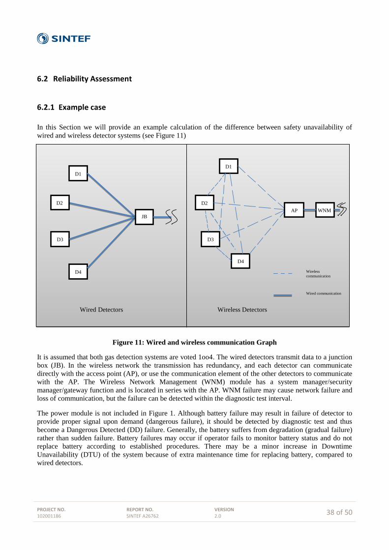
PROJECT NO. 102001186
REPORT NO. SINTEF A26762
VERSION 2.0
38 of 50
6.2 Reliability Assessment
6.2.1 Example case
In this Section we will provide an example calculation of the difference between safety unavailability of
wired and wireless detector systems (see Figure 11)
Figure 11: Wired and wireless communication Graph
It is assumed that both gas detection systems are voted 1oo4. The wired detectors transmit data to a junction
box (JB). In the wireless network the transmission has redundancy, and each detector can communicate
directly with the access point (AP), or use the communication element of the other detectors to communicate
with the AP. The Wireless Network Management (WNM) module has a system manager/security
manager/gateway function and is located in series with the AP. WNM failure may cause network failure and
loss of communication, but the failure can be detected within the diagnostic test interval.
The power module is not included in Figure 1. Although battery failure may result in failure of detector to
provide proper signal upon demand (dangerous failure), it should be detected by diagnostic test and thus
become a Dangerous Detected (DD) failure. Generally, the battery suffers from degradation (gradual failure)
rather than sudden failure. Battery failures may occur if operator fails to monitor battery status and do not
replace battery according to established procedures. There may be a minor increase in Downtime
Unavailability (DTU) of the system because of extra maintenance time for replacing battery, compared to
wired detectors.
D1
D2
D3
D4
JB
D3
D2
D1
D4
AP WNM
Wired Detectors Wireless Detectors
Wireless
communication
Wired communication

PROJECT NO. 102001186
REPORT NO. SINTEF A26762
VERSION 2.0
39 of 50
6.2.2 Example Reliability Block Diagrams
The Reliability Block Diagram (RBD) of wired and wireless systems are shown in Figure 12 and Figure 13,
respectively. The RBD shows how component reliability contributes to the success or failure of a complex
system and is drawn as a series of blocks connected in parallel or series. Each block represents a component
of the system with a failure rate. Parallel paths are redundant, meaning that all of the parallel paths must fail
for the system to fail.
D1
CCFDet
D2
D3
D4
Di: Failure Detecting element i
CCF Det: Common Cause Failure detecting elements
Figure 12: Reliability block diagrams for wired detector system
In the RBD for wireless detector, each wireless detector is split into two elements; the detector element Di
and the detector communication element Ci. It is assumed that the failure rate of the detector element is
independent of the detector communication element. As each detector (Di) in the wireless network has a
communication element (Ci) which can communicate directly with the access point (AP), or can
communicate indirectly with the AP via another communication element (represented with the element Ci-j),
the RBD for wireless detector system becomes more complex than the wired detector system.
In the RBD, the communication path between detectors are not taken into consideration and it is assumed
that each detector communicates with other detectors directly (i.e. without any intermediate block). This
assumption reduces the complexity of the calculations and the effects are negligible as long as the system has
redundant communication paths.
Common Cause Failures (CCF) are important for both systems. CCF of detecting element (CCFDet) and
communication elements (CCFCom) may be caused by hardware related failure, software faults, installation
failure, excessive stress, and operational failures (e.g same operating environment, same vulnerability with
regard to security related risk, same communication protocol, etc. ). One important factor influencing the
reliability of a wireless network is programing of the network protocol which may cause various failure
modes. For instance, a programming error may cause the diagnostic testing to enter into a loop.
There are reported failures in traditional hardwired detectors that are caused by water intrusion in the
Junction boxes (JB) and freezing inside the JB. In wireless detectors the elimination of wires causes
exclusion of the “Junction box”, and consequently no failure of this type.

PROJECT NO. 102001186
REPORT NO. SINTEF A26762
VERSION 2.0
40 of 50
D1
C1-2
C1
C1-3
C1-4
C2
C3
C4
CCFDet
CCFCom
AP WNM
D2
C2-1
C2
C2-3
C2-4
C1
C3
C4
D3
C3-1
C3
C3-2
C3-4
C1
C2
C4
D4
C4-1
C4
C4-2
C4-3
C1
C2
C3
Di: Failure Detecting element i
Ci: Failure Communication element i
Ci-j: Failure Communication element between i and j
CCF Det: Common Cause Failure detecting elements
CCF Com: Common Cause failuree communication elements
AP: Failure Access Point
WNM: Failure Network Monitor
Figure 13: Reliability block diagram for wireless detector system

PROJECT NO. 102001186
REPORT NO. SINTEF A26762
VERSION 2.0
41 of 50
6.2.3 Safety Unavailability Calculation
According to PDS handbook, the calculation of Critical Safety Unavailability (CSU - the probability that the
system fails to automatically carry out successful safety action on the occurrence of a hazardous event) is the
sum of PFD, DTU, and PTIF (probability of test independent failure).
In both a wired and wireless system, the occurrence of one common cause detector failure (CCFDet) will
cause failure upon demand. In a wireless configuration, also the occurrence of one failure of either AP,
WNM, or a common cause communication failure (CCFCom) will cause failure upon demand.
Wired detector system
We can directly apply the PDS model of a 1oo4 voting to calculate PFD, DTU and PTIF. But first we specify
the required input data.
Data on wired IR detector failures are available in the PDS Data handbook. It is noted that the given beta
factor for CCF is comparable to the β-values obtained when using the CCF-checklist in IEC61508-6 [33].
The junction box has for simplicity been assumed to be part of the common cause failure rate of the detector
since the junction box does not have any function besides joining detector wires into one common wire.
Table 2 shows the input parameters applied in the PFD and DTU calculation.
Table 2 Input Parameters
The PDS Handbook now provides the following results for a 1oo4 system of wired detectors. First
𝑃𝐹𝐷𝑤𝑖𝑟𝑒𝑑 ≈ 𝐶1𝑜𝑜4 ∙ 𝛽 ∙ 𝜆𝐷𝑈 ∙ 𝜏2⁄ +
1
5(𝜆𝐷𝑈 ∙ 𝜏)4
Here, of course the first term dominates; this equals 0.3 ∙ 0.06 ∙ 0.6E-6 ∙ 4320/2 ≈ 2.33 × 10⁻⁵, and actually
in total
𝑃𝐹𝐷𝑊𝑖𝑟𝑒𝑑 ≈ 2.3 ∙ 10−5
Next
𝐷𝑇𝑈𝑤𝑖𝑟𝑒𝑑 ≈ 𝐶1𝑜𝑜4 ∙ 𝛽 ∙ 𝜆𝐷𝐷 ∙ 𝑀𝑇𝑇𝑅 + (𝑁(1 − 𝐻𝑁𝛽)𝜆𝐷𝐷 ∙ 𝑀𝑇𝑇𝑅) ∙ (𝐶1𝑜𝑜3 ∙ 𝛽 ∙ 𝜆𝐷𝑈 ∙ 𝜏2⁄ )
Again the first terms dominates, giving 𝐷𝑇𝑈𝑤𝑖𝑟𝑒𝑑 ≈ 0.3∙0.06∙3.4E-6∙3 ≈ 1.84 E-7, and in total
𝐷𝑇𝑈𝑤𝑖𝑟𝑒𝑑 ≈ 2 ∙ 10−7
Finally
𝑃𝑇𝐼𝐹 = 𝐶1𝑜𝑜4 ∙ 𝛽 ∙ 10−3
Detector:
λDU
(per hour)
Detector:
λDD
(per hour)
β
C1004
C1003
H4
𝜏 (hours) MTTR
(hours)
PTIF
(1oo1)
0.6E-6 3.4E-6 0.06 0.3 0.5 1.8 4320 3 0.001

PROJECT NO. 102001186
REPORT NO. SINTEF A26762
VERSION 2.0
42 of 50
Giving (for 1oo4, wired)
𝑃𝑇𝐼𝐹 = 1.8 ∙ 10−5
The estimated CSU for wired detectors voted 1oo4 thus equals:
2.3310−5 + 2 10−7 + 1.8 10−5 ≈ 4.1×10⁻⁵
.
It should be noted that in this example, the contribution from DTU is insignificant compared to the
contributions from PFD and PTIF.
Wireless detector system
For evaluation of PFD for wireless detectors, we restrict to calculating the contributions of the CCFs; which
quite obviously provides the dominating term. In addition to the input data given in Table 2, we need the DU
and DD failure rates for the communication element (C).
The DU failure rate of the communication element is based on the following assumptions and expert
judgments:
There are four opportunities to send a data packet within 1 minute.
If four data packets in sequence are lost, this gives a dangerous failure of the wireless system,
(response time should be less than 1 minute).
The data packets are considered independent; i.e. loss of one data packet has no impact on the failure
of the others.
It is estimated that there is a constant probability of 0.01 for the loss of a specific data packet.
Diagnostic test coverage for the communication element (C), (detection of failure in network) is
assumed to be 85%, i.e. similar to detectors’ test coverage. In fact, the diagnostic test coverage for C
is probably higher than this number, but using 85% will result in a more "conservative" PFD for
wireless systems.
So based on experience from other wireless network and input from experts, the probability of a data packet
loss is estimated to equal 0.01. This probability is an average figure and is highly dependent of the number of
opportunities to send data. The failure rate for the communication element (C) can now be estimated. A
dangerous failure of the system is assumed to occur if four data packets in sequence are lost, and the
probability four packets in sequence being lost now equals 10-8
. As we have 240 packets sent in one hour, the
(upper limit of the) dangerous failure rate will then be 240∙10-8
per hour; (i.e. the rate of losing four data
packets in series during one hour). So for C we get λD = 2.4∙10-6
per hour. Since the diagnostic test coverage
is assumed to be 85%, we get for a C element:
λDU = 0,36∙10-6
per hour
λDD = 2,04∙10-6
per hour
Regarding the betas, the β1 for the detector element (corresponding to CCFDet) is assumed to be identical for
wired and wireless sensors. Estimating β2 for the communication element (corresponding to CCFCom) using
the IEC61508 checklist [33] is challenging. In this CCF-checklist, a major portion of questions and scoring
are relevant for wired gas detection system, but apparently irrelevant for wireless ("common wiring", etc.).
Hence, it is decided to choose β2 for C equal to the β1 for detectors, (equal to the β given in Error!
Reference source not found.).
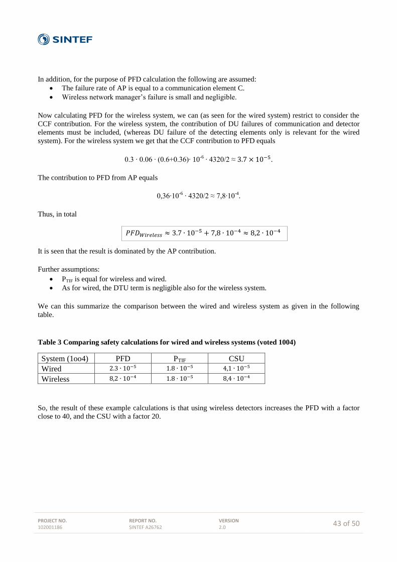
PROJECT NO. 102001186
REPORT NO. SINTEF A26762
VERSION 2.0
43 of 50
In addition, for the purpose of PFD calculation the following are assumed:
The failure rate of AP is equal to a communication element C.
Wireless network manager’s failure is small and negligible.
Now calculating PFD for the wireless system, we can (as seen for the wired system) restrict to consider the
CCF contribution. For the wireless system, the contribution of DU failures of communication and detector
elements must be included, (whereas DU failure of the detecting elements only is relevant for the wired
system). For the wireless system we get that the CCF contribution to PFD equals
0.3 ∙ 0.06 ∙ (0.6+0.36)∙ 10-6
∙ 4320/2 ≈ 3.7 × 10⁻⁵.
The contribution to PFD from AP equals
0,36∙10-6
∙ 4320/2 ≈ 7,8∙10-4
.
Thus, in total
𝑃𝐹𝐷𝑊𝑖𝑟𝑒𝑙𝑒𝑠𝑠 ≈ 3.7 ∙ 10−5 + 7,8 ∙ 10−4 ≈ 8,2 ∙ 10−4
It is seen that the result is dominated by the AP contribution.
Further assumptions:
PTIF is equal for wireless and wired.
As for wired, the DTU term is negligible also for the wireless system.
We can this summarize the comparison between the wired and wireless system as given in the following
table.
Table 3 Comparing safety calculations for wired and wireless systems (voted 1004)
System (1oo4) PFD PTIF CSU
Wired 2.3 ∙ 10−5 1.8 ∙ 10−5 4,1 ∙ 10−5
Wireless 8,2 ∙ 10−4 1.8 ∙ 10−5 8,4 ∙ 10−4
So, the result of these example calculations is that using wireless detectors increases the PFD with a factor
close to 40, and the CSU with a factor 20.
PROJECT NO. 102001186
REPORT NO. SINTEF A26762
VERSION 2.0
44 of 50
7 Case Study: GasSecure
The gas detector is considered a low demand mode instrument. Hence, the considerations from chapter 5
apply. The aim is to design an instrument with SIL2 rating.
7.1 Timing issues
In NORSOK S-001 [41] it is stated that the time from gas exposure until alarm activation should be less than
7 seconds. This time is calculated as the summation of detection time, i.e. 5 seconds, and 2 seconds of
transmitting the data to controller and activation of alarm. In practice, the GS01 uses less than 2 seconds on
detection, but may use more time on the communication depending on the number of retransmission
required. However, care has been taken to keep the total time less than 7 seconds and still comply with the
SIL2 requirements for probability of failure on demand.
The PST for gas detectors is 60 seconds. Recall that this is the time between a dangerous failure and the
rectification to prevent event from occurring. In other words, the control system needs to be aware of any
faulty device well within this time limit.
7.2 Communication considerations
The wireless communication in the GasSecure detector GS01 is handled by ISA100 whereas the safety
communication is covered by PROFIsafe. PROFIsafe covers all the necessary mechanisms to achieve SIL
certification: code name of sender and receiver, CRC verification of data integrity, sequence numbering, and
timeout control.
The safe data exchange takes place between a safety controller and the GS01. The wireless gateway and
possible intermediate routing nodes in the wireless network are considered part of a black channel, i.e. the
elements transport the safety packets only, and the quality of this channel is unknown. The black channel
approach allows safe exchange of data over unqualified communication channels. A prerequisite is that the
contents of the safe data packets are not tampered with by entities in the channel. Retransmissions and FIFOs
are acceptable as long as the incurred delay is not excessive.
The gas detector needs both low power consumption (battery operation) and fast response, to detected gas.
These seemingly contradictory requirements are achieved by delaying the response uplink (UL: GS01 to
controller) to a safe downlink (DL: controller to GS01) request. Having received the DL request, the GS01 is
said to be armed and can respond quickly to the presence of gas. If no gas or other alarm situations are
detected the GS01 responds after a significant part of the process safety time. An example of this mode of
operation in the absence of gas is shown in the below figure.
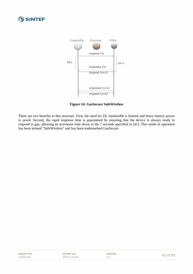
PROJECT NO. 102001186
REPORT NO. SINTEF A26762
VERSION 2.0
45 of 50
Figure 14: GasSecure SafeWireless
There are two benefits to this structure. First, the need for DL bandwidth is limited and hence battery power
is saved. Second, the rapid response time is guaranteed by ensuring that the device is always ready to
respond to gas, allowing an activation time down to the 7 seconds specified in [41]. This mode of operation
has been termed "SafeWireless" and has been trademarked GasSecure.

PROJECT NO. 102001186
REPORT NO. SINTEF A26762
VERSION 2.0
46 of 50
8 Future trends
8.1 Safety topology
GasSecure achieves SIL2 certification using a black channel approach over ISA100.11a, i.e. that the
PROFIsafe entity in the controller communicates directly with the corresponding entity in the GS01 and no
assumptions are made on the design and performance of the communication channel. The future release of
the WirelessHART standard [6] will reportedly also support functional safety, but may use a different model.
Here, the safe entity in the controller will interact with a data storage and -handling entity in the gateway,
known as a proxy. Seen from the controller, the proxy will behave like the end device. The proxy will
receive the data from the devices and make it available to the controller. It is responsible for the verification
of the integrity and timeliness of the data. The proxy is a software entity in the gateway that keeps a
connection open with the end device and offers all the device specific data to the controller.
This deviation from the black channel approach has the clear advantage that there is no need to redesign
existing WirelessHART devices to achieve SIL2 certification. All that is needed is to install new gateways
with a certified proxy. This is a significant simplification for the manufacturers as well as for the device
vendors. It will require a gateway that is developed according to the desired SIL level, because the gateway
with the proxy is now an active part in the safety implementation.
However, it will require a strict certification of the implementation of the WirelessHART protocol. It needs
to be verified that all the possible error conditions (bit errors, packet loss, repetition, masquerading, etc.) are
covered by the protocol and that the implementation of the proxy guarantees that any irregularity is
adequately detected and reported. It is not certain that SIL2 certification can be given on this basis, but there
is a strong industrial interest in getting it done.
The two approaches are fundamentally different. One supports safety all the way to the end device, whereas
the other relies on an intermediate proxy. The pros and cons of both should be clear from the above
discussion. Which approach will eventually dominate remains to be seen and is primarily a question of
industry acceptance.
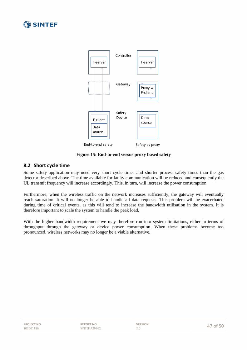
PROJECT NO. 102001186
REPORT NO. SINTEF A26762
VERSION 2.0
47 of 50
Figure 15: End-to-end versus proxy based safety
8.2 Short cycle time
Some safety application may need very short cycle times and shorter process safety times than the gas
detector described above. The time available for faulty communication will be reduced and consequently the
UL transmit frequency will increase accordingly. This, in turn, will increase the power consumption.
Furthermore, when the wireless traffic on the network increases sufficiently, the gateway will eventually
reach saturation. It will no longer be able to handle all data requests. This problem will be exacerbated
during time of critical events, as this will tend to increase the bandwidth utilisation in the system. It is
therefore important to scale the system to handle the peak load.
With the higher bandwidth requirement we may therefore run into system limitations, either in terms of
throughput through the gateway or device power consumption. When these problems become too
pronounced, wireless networks may no longer be a viable alternative.
PROJECT NO. 102001186
REPORT NO. SINTEF A26762
VERSION 2.0
48 of 50
9 Summary and conclusions
The report considers pros and cons of wireless communication in Safety Instrumented Systems (wireless
SIS) in the oil and gas industry. Basic technology and international standards for wireless instrumentation
have been investigated along with the technical requirements which must be fulfilled for a successful
adoption of this new technology.
Main benefits of wireless SIS are substantial reductions in installation cost combined with increased
flexibility in operation.
Wireless SIS is best suited in applications characterized by relatively long cycle times and modest
response time requirements.
Application of wireless SIS requires careful design and consideration in terms of bandwidth
utilization, power consumption, SIL level, and response time.
SIL certification of wireless SIS may be obtained by documenting sufficient control over the
environment in terms of interference and physical obstacles.
Several standard safety protocols such as PROFIsafe can be used to achieve functional safety and
SIL certification.
Functional safety of wireless SIS may also be achieved without a standard protocol, but any solution
will have to prove that it has implemented the four basic elements: data integrity, timeout control,
sequence numbering, and device codename.
Modern wireless techniques such as ISA100 and WirelessHART are capable of handling safety data.
ISA100 can be used 'as is' whereas WirelessHART will need to have some announced safety features
included in the official standard. WLAN and Bluetooth have already been qualified for use with
PROFIsafe.
Main performance limitations inherent to wireless SIS are packet loss and low data bandwidth.
However, these limitations can be overcome with careful consideration of the system's physical
environment.
A serious challenge for battery powered applications is energy consumption at high update rates.
Rapid update cycles require the radio and sensing circuitry to be active for prolonged periods of time
and will drain the batteries. Short battery replacement cycles will tend to negatively affect the
usability of the safety system.

PROJECT NO. 102001186
REPORT NO. SINTEF A26762
VERSION 2.0
49 of 50
References
[1] Chong, C. Y. and Kumar, S. P., "Sensor Networks: Evolution, opportunities and challenges", Proceedings
of the IEEE, Vol. 91, No. 8, Aug. 2003.
[2] IEEE Standard for Information Technology – Telecommunications and information exchange between
systems – Local and Metropolitan networks – Specific requirements – Part 15.4: Wireless Medium
Access Control (MAC) and Physical Layer (PHY) Specifications for Low Rate Wireless Personal Area
Networks (LR-WPANs), IEEE Computer Society, Oct. 2003.
[3] ZigBee Alliance, ZigBee Specification Version 1.0, Dec. 2004.
[4] IEEE Standard for Information Technology – Telecommunications and information exchange between
systems – Local and Metropolitan networks – Specific requirements – Part 15.4: Wireless Medium
Access Control (MAC) and Physical Layer (PHY) Specifications for Low Rate Wireless Personal Area
Networks (LR-WPANs), IEEE Computer Society, 2006.
[5] ZigBee Alliance, ZigBee-2006 Specification, Dec. 2006.
[6] HART Field Communication Protocol Specification, Revision 7.0, HART Communication Foundation,
Sept. 2007.
[7] Industrial Communication Networks – Wireless Communication Network and Communication Profiles –
WirelessHART, International Electrotechnical Commission (IEC) 62591, 2010.
[8] Lennvall, T., Svensson, S. and Hekland, F., "A Comparison of WirelessHART and ZigBee for Industrial
Applications", in Proc. IEEE International Workshop on Factory Communication Systems, May 2008,
pp. 85-88.
[9] ZigBee Alliance, ZigBee PRO Specification, Oct. 2007.
[10] Wireless Systems for Industrial Automation: Process Control and Related Applications, ISA100.11a-
2009, 2009.
[11] Wireless Systems for Industrial Automation: Process Control and Related Applications, ISA100.11a-
2011, 2011.
[12] Industrial Communication Networks – Fieldbus Specifications – WIA-PA Communication Network and
Communication Profile, International Electrotechnical Commission (IEC) 62601, 2009.
[13] IEEE Standard for Local and metropolitan area networks – Part 15.4: Low-Rat Wireless Personal Area
Networks (LR-WPANs) – Amendment 1: MAC sublayer, IEEE Computer Society, April 2012.
[14] Petersen, S. and Carlsen, S., "Wireless Instrumentation in the Oil & Gas Industry - From Monitoring to
Control and Safety Applications", SPE Intelligent Energy International 2012, Utrecht, The Netherlands,
March 27-29, 2012, pp. 1-14.
[15] Radmand, P., Talevski, A., Petersen, S. and Carlsen, S., ”Taxonomy of Wireless Sensor Network Cyber
Security Attacks in the Oil and Gas Industries”, Proceedings of the 24th International Conference on
Advanced Information Networking and Applications, Perth, Western Australia, April 20-23, 2010, pp.
949-957.
[16] Information Technology – Open Systems Interconnection – Basic Reference Model: The Basic Model,
ITU-T X.200 (07/94), 1994.
[17] S. Petersen, P. Doyle, S. Vatland et al., “Requirements, Drivers and Analysis of Wireless Sensor
Network Solutions for the Oil & Gas Industry”, Proc. of the IEEE Conference on Emerging
Technologies and Factory Automation, pp. 219-226, 2007.
[18] ZigBee Alliance, ZigBee IP Specification, Feb. 2013.
[19] Internet Engineering Task Force (IETF) – Request For Comments (RFC) 4911 – IPv6 over Low-Power
Wireless Personal Area Networks (6LoWPANs): Overview, Assumptions, Problem Statement, and
Goals, 2007
[20] Internet Engineering Task Force (IETF) – Request For Comments (RFC) 4944 – Transmission of IPv6
Packets over IEEE 802.15.4 Networks, 2007
[21] L. Angrisani, M. Bertocco, D. Fortin, and A. Sona, ‘‘Experimental study of coexistence issues between
IEEE 802.11b and IEEE Std. 802.15.4 wireless networks,’’ IEEE Trans. Instrum. Meas., vol. 53, no. 8,
pp. 1514–1523, Aug 2008.
PROJECT NO. 102001186
REPORT NO. SINTEF A26762
VERSION 2.0
50 of 50
[22] D. Chen and P. K. Varshney, "QoS Support in Wireless Sensor Networks: A Survey", Communication
13244, 2004, pp. 227–233.
[23] M. A. Yigitel, O. D. Incel and C. Ersoy, "QoS-aware MAC protocols for wireless sensor networks: A
survey", Computer Networks 55, 2011, pp. 1982-2004.
[24] R. Braden, D. Clark and S. Shenker, "Integrated services in the internet architecture – An overview",
IETF RFC 1663, June 1994.
[25] S. Blake et.al, "An architecture for differentiated services", IETF RFC 2475, Dec. 1998.
[26] S. Bhatnagar, B. Deb and B. Nath, "Service differentiation in Sensor Networks", Proc. of Int.
Symposium on Wireless Personal Multimedia Communications, Aalborg, Denmark, Sept. 9-12, 2001.
[27] International Electrotechnical Commission (IEC), IEC 61508 – Functional safety of
electrical/electronic/programmable electronic safety-related systems - ALL PARTS, 2010.
[28] International Electrotechnical Commission (IEC), IEC 61784-3-3 – Industrial communication networks
– Profiles – Part 3-3: Functional safety fieldbuses – Additional specifications for CPF 3, 2007.
[29] International Electrotechnical Commission (IEC), IEC 61158 – Industrial communication networks –
Fieldbus specifications, 2007.
[30] Ikram, W. et al., "Towards the Development of a SIL Compliant Wireless Hydrocarbon Leakage
Detection System", Proceedings of the International Conference on Emerging Technologies and Factory
Automation, Cagliari, Italy, Sept. 10-13, 2013, pp. 1-8.
[31] NAMUR NE 124:2010, “Wireless Automation Requirements”, 2010.
[32] European Parliament and the Council, Directive 94/9/EC, 1994.
[33] International Electrotechnical Commission (IEC), IEC 61508 – Functional safety of
electrical/electronic/programmable electronic safety-related systems - ALL PARTS, 2010.
[34] Carlsen, S., Skavhaug, A., Petersen, S. and Doyle, P., “Wireless sensor network installed on a North Sea
platform”, World Oil, Vol. 230, No. 9, Sept. 2009, pp. 93-97.
[35] Petersen, S. and Carlsen, S., “Performance Evaluation of WirelessHART for Factory Automation”,
Proceedings of the 14th IEEE International Conference on Emerging Technologies and Factory
Automation, Palma, Mallorca, Spain, Sept. 22-26, 2009, pp. 1-9.
[36] Functional safety of electrical/electronic/programmable electronic safety-related systems, Edition 2.0.,
International Electrotechnical Commission (IEC) 61508, 2010.
[37] Functional safety – Safety instrumented systems for the process industry sector, International
Electrotechnical Commission (IEC) 61511, 2004.
[38] Industrial Communication Networks – Profiles – Part 3: Functional safety Fieldbuses – General rules and
profile definitions, Edition 2.0, International Electrotechnical Commission (IEC) 61784-3, 2010.
[39] Industrial Communication Networks – Profiles – Part 3-3: Functional safety Fieldbuses – Additional
Specifications for CPF 3, Edition 2.0, International Electrotechnical Commission (IEC) 61784-3-3, 2010.
[40] PDS Method Handbook, 2013
[41] NORSOK S-001

Technology for a better society
www.sintef.no
Top Related