


Languages
Pages
Legal

Polarization Tools Selection GuidePages 974-994
Polarization Measurement and Control■ PAX5700 Series – High-Precision and High-Power Range Polarimeter
(Page 976)– Available for the Wavelength Range of 400nm to 1700nm
■ DPC5500 Series – Deterministic Polarization Controller (Page 979)– Polarization can be Deterministically Set Within 150µs (Typically) and
Locked to a Specific State, Which is Independent of the Input Polarization ■ IPM5300 – In-Line Fiber Polarimeter (Page 980)
– Operating Wavelength Range of 1200nm to 1700nm– Calibrated for the C and L Bands
■ PL100 Series – SOP Locker (Page 982)– Allows State of Polarization (SOP) Adjustment Manually via the Front
Panel– Does Not Depend on the Input Polarization
■ Manual Polarization Controllers (Page 983)– These Devices Provide Manual Polarization Control for Fiber Based
Experiment
PMD5000 Series – PMD PDL Measurement Systems■ These systems are preconfigured for most industry and research applications.
User configurations for already installed fiber applications as well as PMDmonitoring of busy fibers are available.
See Pages 984-987
Polarization Accessories■ Achromatic Wave Plates■ Zero-Order Wave Plates■ Multi-Order Wave Plates■ Telecom Wave Plates■ Fiber U-Bench Polarization Controller■ Soleil-Babinet Compensator■ Glan-Laser Calcite Polarizers■ Glan-Taylor Calcite Polarizers■ Polarizing Prism Mounts■ Depolarizers
See Pages 988-994
974 www.thorlabs.com
PMD/PDLMeasurements
PolarizationAccessories
PolarizationMeasurement & Control
CONTROLLERWAVELENGTH ANALYZER MANUAL AUTOMATIC TYPE MODEL APPLICATIONS
400-700nm Rotating PAX5710 Series Polarimetry, Retardance700-1000nm
✔Wave Plate PAX5720 Series Measurements, ER-
1000-1350nm Measurements on PMF, 1300-1700nm PMD, PDL Measurements1200-1700nm
✔In-Line IPM5300 Polarimetry, PMD/PDL
Module & Benchtop Measurements1200-1700nm In-Line DPC5500 Polarimetry, SOP Control &
✔ ✔ Module & Benchtop Scrambling, PMD/PDLMeasurements
1200-1700nm✔ ✔
In-Line PL100S/PL100P SOP Control andSOP Lockers Scrambling
Fiber Dependent ✔ In-Line FPC Series SOP Control
140-400nm Retarder SBC Series Retardance Measurement,
400-1000nm ✔ Soleil-Babinet Ellipsometry, Birefringence
1000-2000nm Compensator Compensation
Polarimeter Selection Table
1_PolMeas_Cont 974-983.qxd.P 7/20/07 2:16 PM Page 974
PMD/PDL MeasurementsPMD5000 Series – Polarization Measurement Systems■ Analyze Highly Accurate Polarization Related Effects in Fiber Optic
Systems Based on Jones Matrix■ Powerful and Flexible Solution for all Kinds of PMD/PDL Related
Measurements
See Pages 984-987
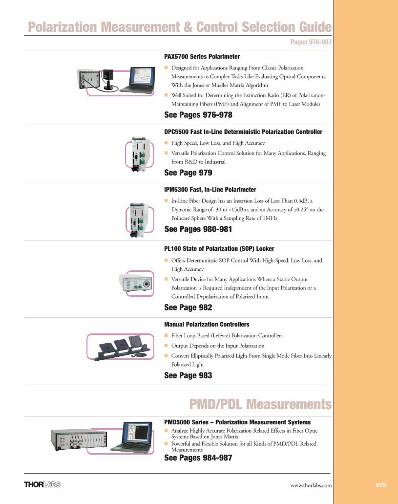
PAX5700 Series Polarimeter
■ Designed for Applications Ranging From Classic Polarization
Measurements to Complex Tasks Like Evaluating Optical Components
With the Jones or Mueller Matrix Algorithm
■ Well Suited for Determining the Extinction Ratio (ER) of Polarization-
Maintaining Fibers (PMF) and Alignment of PMF to Laser Modules
See Pages 976-978
DPC5500 Fast In-Line Deterministic Polarization Controller
■ High Speed, Low Loss, and High Accuracy
■ Versatile Polarization Control Solution for Many Applications, Ranging
From R&D to Industrial
See Page 979
IPM5300 Fast, In-Line Polarimeter
■ In-Line Fiber Design has an Insertion Loss of Less Than 0.5dB, a
Dynamic Range of -30 to +15dBm, and an Accuracy of ±0.25° on the
Poincaré Sphere With a Sampling Rate of 1MHz
See Pages 980-981
PL100 State of Polarization (SOP) Locker
■ Offers Determinitstic SOP Control With High-Speed, Low Loss, and
High Accuracy
■ Versatile Device for Many Applications Where a Stable Output
Polarization is Required Independent of the Input Polarization or a
Controlled Depolarization of Polarized Input
See Page 982
Manual Polarization Controllers
■ Fiber Loop-Based (Lefévre) Polarization Controllers
■ Output Depends on the Input Polarization
■ Convert Elliptically Polarized Light From Single Mode Fiber Into Linearly
Polarized Light
See Page 983
975www.thorlabs.com
Polarization Measurement & Control Selection GuidePages 976-987
1_PolMeas_Cont 974-983.qxd.P 7/20/07 12:22 PM Page 975
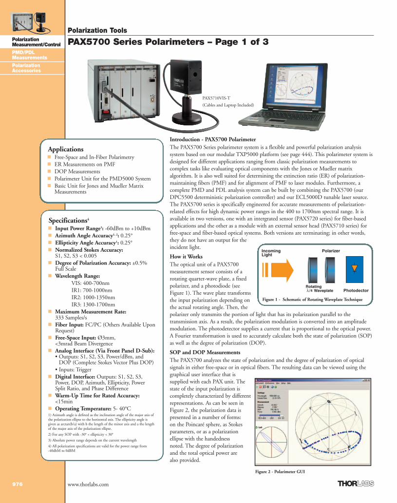
Introduction - PAX5700 PolarimeterThe PAX5700 Series polarimeter system is a flexible and powerful polarization analysissystem based on our modular TXP5000 platform (see page 444). This polarimeter system isdesigned for different applications ranging from classic polarization measurements tocomplex tasks like evaluating optical components with the Jones or Mueller matrixalgorithm. It is also well suited for determining the extinction ratio (ER) of polarization-maintaining fibers (PMF) and for alignment of PMF to laser modules. Furthermore, acomplete PMD and PDL analysis system can be built by combining the PAX5700 (ourDPC5500 deterministic polarization controller) and our ECL5000D tunable laser source.The PAX5700 series is specifically engineered for accurate measurements of polarization-related effects for high dynamic power ranges in the 400 to 1700nm spectral range. It isavailable in two versions, one with an intergrated sensor (PAX5720 series) for fiber-basedapplications and the other as a module with an external sensor head (PAX5710 series) forfree-space and fiber-based optical systems. Both versions are terminating; in other words,they do not have an output for theincident light.
How it WorksThe optical unit of a PAX5700measurement sensor consists of arotating quarter-wave plate, a fixedpolarizer, and a photodiode (see Figure 1). The wave plate transformsthe input polarization depending onthe actual rotating angle. Then, thepolarizer only transmits the portion of light that has its polarization parallel to thetransmission axis. As a result, the polarization modulation is converted into an amplitudemodulation. The photodetector supplies a current that is proportional to the optical power.A Fourier transformation is used to accurately calculate both the state of polarization (SOP)as well as the degree of polarization (DOP).
SOP and DOP MeasurementsThe PAX5700 analyzes the state of polarization and the degree of polarization of opticalsignals in either free-space or in optical fibers. The resulting data can be viewed using thegraphical user interface that issupplied with each PAX unit. Thestate of the input polarization iscompletely characterized by differentrepresentations. As can be seen inFigure 2, the polarization data ispresented in a number of forms: on the Poincaré sphere, as Stokesparameters, or as a polarization ellipse with the handedness noted. The degree of polarization and the total optical power are also provided.
Polarization Tools
976
PolarizationMeasurement/Control
PMD/PDLMeasurements
PolarizationAccessories
www.thorlabs.com
PAX5700 Series Polarimeters – Page 1 of 3
Figure 1 - Schematic of Rotating Waveplate Technique
Figure 2 - Polarimeter GUI
Specifications4
■ Input Power Range3: -60dBm to +10dBm■ Azimuth Angle Accuracy1, 2: 0.25°■ Ellipticity Angle Accuracy1: 0.25°■ Normalized Stokes Accuracy:
S1, S2, S3 < 0.005■ Degree of Polarization Accuracy: ±0.5%
Full Scale■ Wavelength Range:
VIS: 400-700nmIR1: 700-1000nmIR2: 1000-1350nmIR3: 1300-1700nm
■ Maximum Measurement Rate:333 Samples/s
■ Fiber Input: FC/PC (Others Available UponRequest)
■ Free-Space Input: Ø3mm, <3mrad Beam Divergence
■ Analog Interface (Via Front Panel D-Sub):• Outputs: S1, S2, S3, Power/dBm, and
DOP (Complete Stokes Vector Plus DOP) • Inputs: Trigger
■ Digital Interface: Outputs: S1, S2, S3,Power, DOP, Azimuth, Ellipticity, PowerSplit Ratio, and Phase Difference
■ Warm-Up Time for Rated Accuracy:<15min
■ Operating Temperature: 5- 40°C1) Azimuth angle is defined as the inclination angle of the major axis ofthe polarization ellipse to the horizontal axis. The ellipticity angle isgiven as arctan(b/a) with b the length of the minor axis and a the lengthof the major axis of the polarization ellipse.
2) For any SOP with -30° < ellipticity < 30°
3) Absolute power range depends on the current wavelength
4) All polarization specifications are valid for the power range from -40dbM to 0dBM
Applications■ Free-Space and In-Fiber Polarimetry■ ER Measurements on PMF■ DOP Measurements■ Polarimeter Unit for the PMD5000 System■ Basic Unit for Jones and Mueller Matrix
Measurements
PAX5710VIS-T
(Cables and Laptop Included)
1_PolMeas_Cont 974-983.qxd.P 7/13/07 1:21 PM Page 976
Polarization Tools
977
PolarizationMeasurement/Control
PMD/PDLMeasurements
PolarizationAccessories
www.thorlabs.com
PAX5700 Series Polarimeters – Page 2 of 3Long-Term Polarization MeasurementsAnother standard feature is the scope mode, whichlooks similar to an oscilloscope display. Thepolarization can be examined continuously over timeor initiated with a software or hardware trigger signal.The number of data points to be acquired can bechosen by the user. Another feature is the pre-triggerfunction, which can be activated in each triggermode. A user-configurable number of samples arestored in a ring buffer until the trigger pulse is given.All acquired data before and after the trigger pulse aredisplayed in a diagram. Therefore, a real-timemonitoring of the system's polarization behavior canbe realized with the PAX measurement system. Themeasured data can be stored in an ASCII format file(CSV). The data file contents can be viewed with anytext editor and can be further processed using third-party software packages such as MathCAD,Mathematica, or Excel.
Software FeaturesThe software for the PAX system includes drivers forLabVIEW™, LabWindows™/CVI™, MSVC, andBorland C. These drivers enable you to write yourown applications to adapt the polarimeter into acomplete optical setup. Included in the software arefeatures specifically geared for extinction ratio (ER)measurements (see below).
System ConfigurationsDue to its modular design and the various modelsavailable, the PAX system is an ideal tool for varioustypes of polarization-related measurement tasks inR&D laboratories as well as for final inspection inmanufacturing. The PAX5700 series can be used forfree-space and fiber-based applications covering the400 to 1700nm wavelength range. See the followingpage for ordering information.
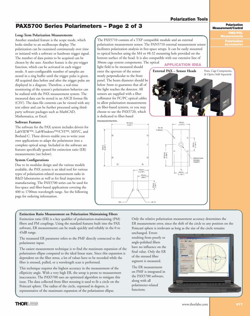
The PAX5710 consists of a TXP compatible module and an externalpolarization measurement sensor. The PAN5710 external measurement sensorfacilitates polarization analysis in free-space setups. It can be easily mountedto optical benches using the M4 or #8-32 mounting hole provided on thebottom surface of the head. It is also compatible with our extensive line of30mm cage system components. The opticallight field to be measured shouldenter the aperture of the sensornearly perpendicular to the frontpanel. The beam diameter should bebelow 3mm to guarantee that all ofthe light reaches the detector. Allsensors are supplied with a fibercollimator for FC/PC optical cablesto allow polarization measurementson fiber-based systems, or you maychoose to use the PAX5720, whichis dedicated to fiber-basedmeasurements.
Posts, Cage Components, & Optics Sold Separately
Extinction Ratio Measurement on Polarization Maintaining FibersExtinction ratio (ER) is a key qualifier of polarization-maintaining (PM)fibers and PM couplings. Using the standard features built into the PAXsoftware, ER measurements can be made quickly and reliably in the 0 to45dB range.
The measured ER parameter refers to the PMF directly connected to thepolarimeter input.
The easiest measurement technique is to find the maximum expansion of thepolarization ellipse compared to the ideal linear state. Since this expansion isdependent on the fiber stress, a lot of values have to be recorded while thefiber is stressed, pulled, or a wavelength scan is performed.
This technique requires the highest accuracy in the measurement of theellipticity angle. With a very high ER, the setup is prone to measurementinaccuracies. The PAX5700 uses an optimized algorithm to mitigate thisissue. The data collected from fiber stressing is used to fit a circle on thePoincaré sphere. The radius of the circle, expressed in degrees, isrepresentative of the maximum expansion of the polarization ellipse.
Only the relative polarization measurement accuracy determines the ER measurement error, since the shift of the circle to any position on thePoincaré sphere is irrelevant as long as the size of the circle remainsunchanged. Errorsresulting from poorly orangle-polished fibershave no influence on thefinal value. Only the ERof the stressed fibersegment is measured.
The ER measurementon PMF is integrated inthe PAX5700 software,along with allpolarimeter-relatedfunctions.
External PAX – Sensor Heads
APPLICATION IDEA
1_PolMeas_Cont 974-983.qxd.P 7/13/07 1:22 PM Page 977
Polarization Tools
978
PolarizationMeasurement/Control
PMD/PDLMeasurements
PolarizationAccessories
www.thorlabs.com
PAX5700 Series Polarimeters (Selection & Pricing Guide )
ITEM# $ £ € RMB DESCRIPTION
PAX5710VIS-T $ 7,788.00 £ 4,906.40 € 7.242,80 ¥ 74,375.40 TXP Polarimeter w/ External Sensor (400-700nm )PAX5710IR1-T $ 7,788.00 £ 4,906.40 € 7.242,80 ¥ 74,375.40 TXP Polarimeter w/ External Sensor (700-1000nm) PAX5710IR2-T $ 7,788.00 £ 4,906.40 € 7.242,80 ¥ 74,375.40 TXP Polarimeter w/ External Sensor (1000-1350nm) PAX5710IR3-T $ 7,788.00 £ 4,906.40 € 7.242,80 ¥ 74,375.40 TXP Polarimeter w/ External Sensor (1300-1700nm)
PAX5710VIS-TCables, External Sensor Head, and Laptop Included (All Sensor Heads are Factory Calibrated)
PAX5720VIS-TCables, Internal Sensor, andLaptop Included
ITEM# $ £ € RMB DESCRIPTION
PAX5720VIS-T $ 7,788.00 £ 4,906.40 € 7.242,80 ¥ 74,375.40 TXP Polarimeter w/ Internal Sensor (400-700nm) PAX5720IR1-T $ 7,788.00 £ 4,906.40 € 7.242,80 ¥ 74,375.40 TXP Polarimeter w/ Internal Sensor (700-1000nm) PAX5720IR2-T $ 7,788.00 £ 4,906.40 € 7.242,80 ¥ 74,375.40 TXP Polarimeter w/ Internal Sensor (1000-1350nm) PAX5720IR3-T $ 7,788.00 £ 4,906.40 € 7.242,80 ¥ 74,375.40 TXP Polarimeter w/ Internal Sensor (1300-1700nm )
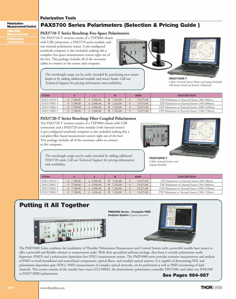
PAX5710-T Series Benchtop Free-Space PolarimetersThe PAX5710-T versions consist of a TXP5004 chassiswith USB connection, a PAX5710 series module, andone external polarimeter sensor. A pre-configurednotebook computer is also included, making this acomplete free-space measurement system right out ofthe box. This package includes all of the necessarycables to connect to the sensor and computer.
Putting it All Together
The PMD5000 Series combines the modularity of Thorlabs’ Polarization Measurement and Control System with a powerful tunable laser source tooffer a powerful and flexible solution to measurement tasks. With their specialized software package, they form a versatile polarization modedispersion (PMD) and a polarization dependent loss (PDL) measurement system. The PMD5000 series provides extensive measurement and analysisof PMD on both broadband and narrowband components, optical fibers, and installed optical systems. It is capable of determining PDL andpolarization dependent gain (PDG). PMD measurements of complex optical networks can be performed as well as PMD monitoring of darkchannels. This system consists of the tunable laser source ECL5000D, the deterministic polarization controller DPC5500, and either our IPM5300or PAX5720IR3 polarimeters.
The wavelength range can be easily extended by purchasing new sensorheads or by adding additional module and sensor heads. Call ourTechnical Support for pricing information and availability.
The wavelength range can be easily extended by adding additionalPAX5720 cards. Call our Technical Support for pricing informationand availability.
See Pages 984-987
PMD5000 Series - Complete PMDAnalysis System (Laptop Included)
PAX5720-T Series Benchtop Fiber Coupled PolarimetersThe PAX5720-T versions consist of a TXP5004 chassis with USBconnection and a PAX5720 series module (with internal sensor).A pre-configured notebook computer is also included making this acomplete fiber based measurement system right out of the box!This package includes all of the necessary cables to connectto the computer.
1_PolMeas_Cont 974-983.qxd.P 7/20/07 12:40 PM Page 978
Polarization Tools
979
PolarizationMeasurement/Control
PMD/PDLMeasurements
PolarizationAccessories
www.thorlabs.com
from the polarimeter and drives the non-deterministic SOP controller,which is comprised of a multitude of piezoelectric based fibersqueezers. A simple yet robust calibration algorithm accounts for theinherent nonlinearities in the piezoelectric elements and allows foraccurate and stable deterministic SOP control.
This facilitates SOP control at a user-defined location in theoptical system such that the SOP can be varied to accurately andprecisely follow a prescribed path on the Poincaré sphere (seeFigure 1).
Comparison to Existing Systems The DPC5500 eliminates the inadequacies of mostcommercially available SOP controllers whose output SOPdepends on the input SOP. Any input SOP change willimplicitly lead to a corresponding output SOP rotation. Inaddition, most commercial high-speed SOP controllers are trial and error controllers and suffer from drift andhysteresis effects. They are non-deterministic and aredependent on environmental and prior conditions. This all-fiber technology provides deterministic control with verylow insertion loss. The desired SOP may either be defined via its azimuth/ellipticity parameters or its corresponding Stokes values, which are graphically defined by a point on thePoincaré sphere or electronically defined by supplying afeedback signal from a control loop.
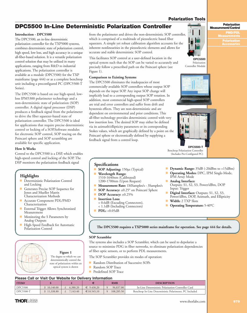
Introduction - DPC5500The DPC5500, an in-line deterministicpolarization controller for the TXP5000 systems,combines deterministic state of polarization control,high speed, low loss, and high accuracy in a uniqueall-fiber-based solution. It is a versatile polarizationcontrol solution that may be utilized in manyapplications, ranging from R&D to industrialapplications. The polarization controller isavailable as a module (DPC5500) for the TXPmainframe (page 444) or as a complete benchtopunit including a preconfigured PC (DPC5500-TSeries).
The DPC5500 is based on our high-speed, low-loss IPM5300 polarimeter technology and anon-deterministic state of polarization (SOP)controller. A digital signal processor (DSP)produces a feedback signal from the polarimeterto drive the fiber squeezer-based state ofpolarization controller. The DPC5500 is idealfor applications that require precise deterministiccontrol or locking of a SOP.Software modulesfor electronic SOP control, SOP tracing on thePoincaré sphere and SOP scrambling areavailable for specific application.
How It WorksCentral to the DPC5500 is a DSP, which enableshigh-speed control and locking of the SOP. TheDSP monitors the polarization feedback signal
SOP ScramblerThe systems also includes a SOP Scrambler, which can be used to depolarize asource to minimize PDG in fiber networks, to eliminate polarization dependenciesof fiber optic sensors, or to perform PDL measurements.
The SOP Scrambler provides six modes of operation:
■ Random Distribution of Successive SOPs■ Random SOP Trace■ Predefined SOP Trace
ITEM# $ £ € RMB DESCRIPTION
DPC5500 $ 10,140.00 £ 6,388.20 € 9.430,20 ¥ 96,837.00 In-Line Deterministic Polarization Controller CardDPC5500-T $ 11,338.80 £ 7,143.40 €10.545,10 ¥ 108,285.50 Benchtop In-Line Deterministic Polarimeter, PC Included
Please Call or Visit Our Website for Delivery Information
Highlights■ Deterministic Polarization Control
and Locking■ Generates Precise SOP Sequence for
Jones and Mueller MatrixCharacterization Methods
■ Accurate Component PDL/PMDCharacterization
■ External Trigger Allows SynchronizedMeasurement
■ Monitoring the S Parameters byAnalog Outputs
■ High-Speed Feedback for AutomaticPolarization Control
DPC5500 In-Line Deterministic Polarization Controller
Figure 1The degree to which we candeterministically control the
state of polarization within anoptical system is shown
Specifications■ SOP Adjusting: 150µs (Typical)■ Wavelength Range:
1510-1640nm (Calibrated)1200-1700nm (Upon Request)
■ Measurement Rate: 1MSamples/s - 3Samples/s■ SOP Accuracy: ±0.25° on Poincaré Sphere ■ DOP Accuracy: ±0.25% ■ Insertion Loss:
< 0.6dB (Excuding Connectors),< 1.1dB (Including Connectors)
■ PDL: <0.05dB
■ Dynamic Range: 35dB (-20dBm to +15dBm)■ Operating Modes: DPC, IPM Single-Mode,
IPM Array Mode■ Analog Interface:
Outputs: S1, S2, S3, Power/dBm, DOPInput: Trigger
■ Digital Interface: Outputs: S1, S2, S3,Power/dBm, DOP, Azimuth, and Ellipticity
■ Width: 2 TXP Slots ■ Operating Temperature: 5-40°C
The DPC5500 requires a TXP5000 series mainframe for operation. See page 444 for details.
DPC5500Polarization
Controller Module
DPC5500-TBenchtop Polarization Controller
(Includes Pre-Configured PC)
1_PolMeas_Cont 974-983.qxd.P 7/13/07 1:23 PM Page 979
Polarization Tools
980
PolarizationMeasurement/Control
PMD/PDLMeasurements
PolarizationAccessories
www.thorlabs.com
IPM5300 In-Line Polarimeter – Page 1 of 2Introduction - IPM5300 Fast In-Line PolarimeterThe IPM5300 fiber optic polarimeter module enables high-speed measurements of the state ofpolarization (SOP). The in-line fiber design has an insertion loss of less than 0.6dB, a dynamic range of45dBm, and an accuracy of ±0.25° on the Poincaré sphere with a sampling rate of 1MHz. TheIPM5300 series is available as a module for the TXP mainframe (page 444) or as a complete benchtopunit including preconfigured PC (IPM5300-T series).
This all fiber polarimeter is based on patented FBG technology. It provides a novel combinationof in-line polarimetric measurement, low insertion loss, high speed, and accuracy that enables
unprecedented measurement control of the SOP in fiber optic applications.
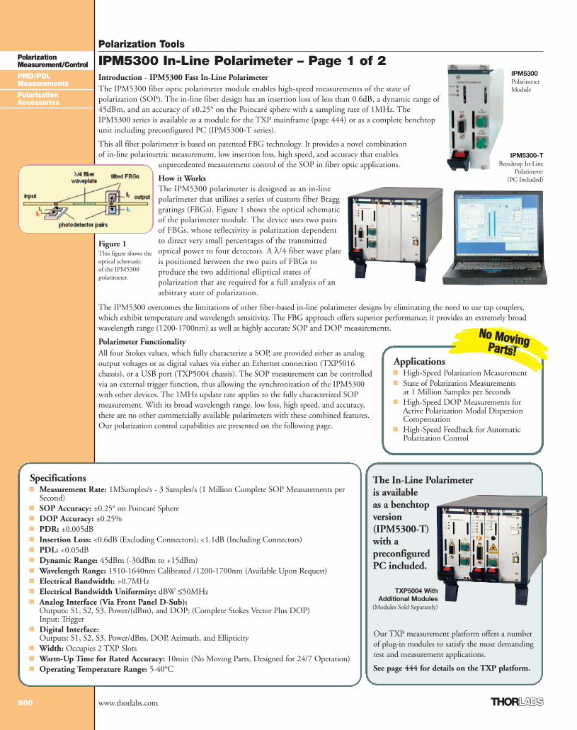
How it WorksThe IPM5300 polarimeter is designed as an in-linepolarimeter that utilizes a series of custom fiber Bragggratings (FBGs). Figure 1 shows the optical schematicof the polarimeter module. The device uses two pairsof FBGs, whose reflectivity is polarization dependentto direct very small percentages of the transmittedoptical power to four detectors. A λ/4 fiber wave plateis positioned between the two pairs of FBGs toproduce the two additional elliptical states ofpolarization that are required for a full analysis of anarbitrary state of polarization.
The IPM5300 overcomes the limitations of other fiber-based in-line polarimeter designs by eliminating the need to use tap couplers,which exhibit temperature and wavelength sensitivity. The FBG approach offers superior performance; it provides an extremely broadwavelength range (1200-1700nm) as well as highly accurate SOP and DOP measurements.
Polarimeter FunctionalityAll four Stokes values, which fully characterize a SOP, are provided either as analogoutput voltages or as digital values via either an Ethernet connection (TXP5016chassis), or a USB port (TXP5004 chassis). The SOP measurement can be controlledvia an external trigger function, thus allowing the synchronization of the IPM5300with other devices. The 1MHz update rate applies to the fully characterized SOPmeasurement. With its broad wavelength range, low loss, high speed, and accuracy,there are no other commercially available polarimeters with these combined features.Our polarization control capabilities are presented on the following page.
Specifications■ Measurement Rate: 1MSamples/s - 3 Samples/s (1 Million Complete SOP Measurements per
Second)■ SOP Accuracy: ±0.25° on Poincaré Sphere■ DOP Accuracy: ±0.25%■ PDR: ±0.005dB■ Insertion Loss: <0.6dB (Excluding Connectors); <1.1dB (Including Connectors)■ PDL: <0.05dB■ Dynamic Range: 45dBm (-30dBm to +15dBm)■ Wavelength Range: 1510-1640nm Calibrated /1200-1700nm (Available Upon Request)■ Electrical Bandwidth: >0.7MHz■ Electrical Bandwidth Uniformity: dBW ≤50MHz■ Analog Interface (Via Front Panel D-Sub):
Outputs: S1, S2, S3, Power/(dBm), and DOP; (Complete Stokes Vector Plus DOP)Input: Trigger
■ Digital Interface:Outputs: S1, S2, S3, Power/dBm, DOP, Azimuth, and Ellipticity
■ Width: Occupies 2 TXP Slots■ Warm-Up Time for Rated Accuracy: 10min (No Moving Parts, Designed for 24/7 Operation)■ Operating Temperature Range: 5-40°C
Figure 1This figure shows theoptical schematicof the IPM5300polarimeter.
Our TXP measurement platform offers a numberof plug-in modules to satisfy the most demandingtest and measurement applications.
See page 444 for details on the TXP platform.
Applications■ High-Speed Polarization Measurement■ State of Polarization Measurements
at 1 Million Samples per Seconds■ High-Speed DOP Measurements for
Active Polarization Modal DispersionCompensation
■ High-Speed Feedback for AutomaticPolarization Control
NNoo MMoovviinnggPPaarrttss!!
The In-Line Polarimeter is available as a benchtop version (IPM5300-T) with apreconfigured PC included.
TXP5004 With Additional Modules
(Modules Sold Separately)
IPM5300Polarimeter Module
IPM5300-TBenchtop In-Line
Polarimeter(PC Included)
1_PolMeas_Cont 974-983.qxd.P 7/13/07 1:23 PM Page 980
Polarization Tools
981
PolarizationMeasurement/Control
PMD/PDLMeasurements
PolarizationAccessories
www.thorlabs.com
ITEM# $ £ € RMB DESCRIPTION
IPM5300 $ 8,760.00 £ 5,518.80 € 8.146,80 ¥ 83,658.00 In-Line Polarimeter CardIPM5300-T $ 9,958.80 £ 6,274.00 € 9.261,70 ¥ 95,106.50 Benchtop In-Line Polarimeter, Including Preconfigured PC
High-Speed In-Line Polarimeter Module and Chassis
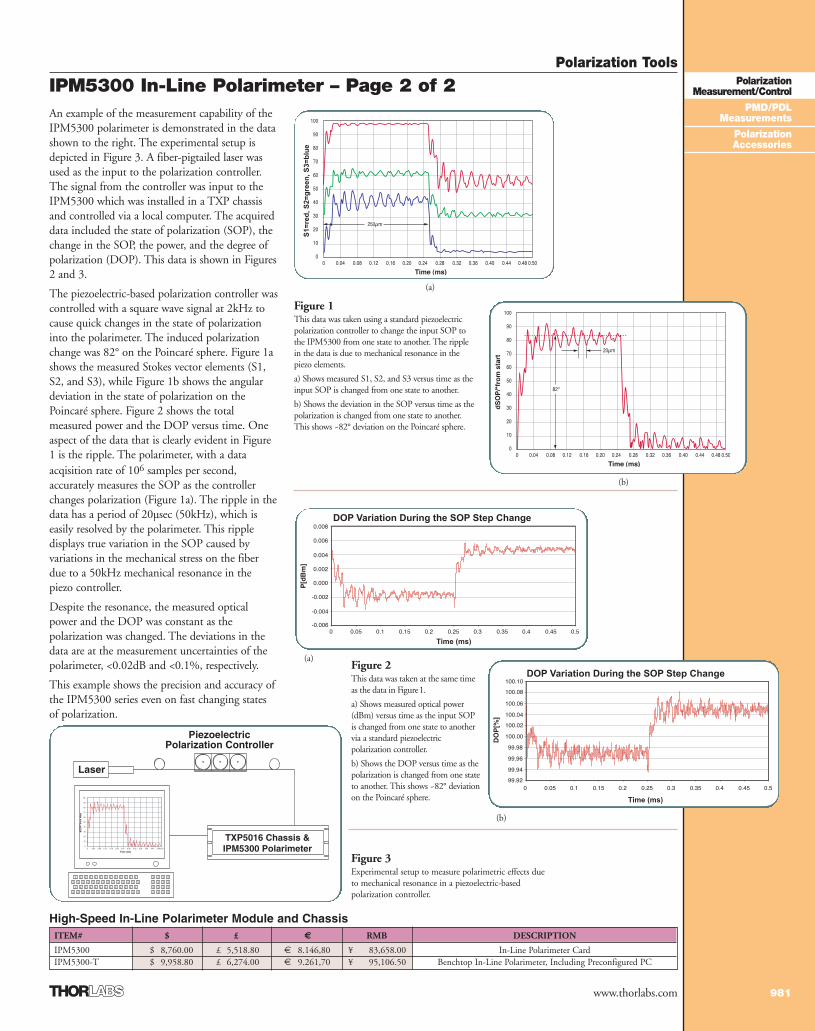
An example of the measurement capability of theIPM5300 polarimeter is demonstrated in the datashown to the right. The experimental setup isdepicted in Figure 3. A fiber-pigtailed laser wasused as the input to the polarization controller.The signal from the controller was input to theIPM5300 which was installed in a TXP chassisand controlled via a local computer. The acquireddata included the state of polarization (SOP), thechange in the SOP, the power, and the degree ofpolarization (DOP). This data is shown in Figures2 and 3.
The piezoelectric-based polarization controller wascontrolled with a square wave signal at 2kHz tocause quick changes in the state of polarizationinto the polarimeter. The induced polarizationchange was 82° on the Poincaré sphere. Figure 1ashows the measured Stokes vector elements (S1,S2, and S3), while Figure 1b shows the angulardeviation in the state of polarization on thePoincaré sphere. Figure 2 shows the totalmeasured power and the DOP versus time. Oneaspect of the data that is clearly evident in Figure1 is the ripple. The polarimeter, with a dataacqisition rate of 106 samples per second,accurately measures the SOP as the controllerchanges polarization (Figure 1a). The ripple in thedata has a period of 20µsec (50kHz), which iseasily resolved by the polarimeter. This rippledisplays true variation in the SOP caused byvariations in the mechanical stress on the fiberdue to a 50kHz mechanical resonance in thepiezo controller.
Despite the resonance, the measured opticalpower and the DOP was constant as thepolarization was changed. The deviations in thedata are at the measurement uncertainties of thepolarimeter, <0.02dB and <0.1%, respectively.
This example shows the precision and accuracy ofthe IPM5300 series even on fast changing statesof polarization.
Figure 1This data was taken using a standard piezoelectricpolarization controller to change the input SOP tothe IPM5300 from one state to another. The ripplein the data is due to mechanical resonance in thepiezo elements.
a) Shows measured S1, S2, and S3 versus time as theinput SOP is changed from one state to another.
b) Shows the deviation in the SOP versus time as thepolarization is changed from one state to another.This shows ~82° deviation on the Poincaré sphere.
Figure 3Experimental setup to measure polarimetric effects dueto mechanical resonance in a piezoelectric-basedpolarization controller.
DOP Variation During the SOP Step Change
Time (ms)
Figure 2This data was taken at the same timeas the data in Figure1.
a) Shows measured optical power(dBm) versus time as the input SOPis changed from one state to anothervia a standard piezoelectricpolarization controller.
b) Shows the DOP versus time as thepolarization is changed from one stateto another. This shows ~82° deviationon the Poincaré sphere.
(b)
(a)
DOP Variation During the SOP Step Change
Time (ms)
(b)
S1=
red
, S2=
gre
en, S
3=b
lue
(a)
IPM5300 In-Line Polarimeter – Page 2 of 2
TXP5016 Chassis &IPM5300 Polarimeter
PiezoelectricPolarization Controller
Laser
1_PolMeas_Cont 974-983.qxd.P 7/13/07 1:23 PM Page 981
Polarization Tools
982
PolarizationMeasurement/Control
PMD/PDLMeasurements
PolarizationAccessories
www.thorlabs.com
ITEM# $ £ € RMB DESCRIPTION
PL100S $ 9,600.00 £ 6,048.00 € 8.928,00 ¥ 91,680.00 SOP Locker for SMF FC/APC Connectors*PL100P $ 9,000.00 £ 5,670.00 € 8.370,00 ¥ 85,950.00 SOP Locker for PMF FC/APC Connectors*
Specifications■ Wavelength Range: 1200-1700nm■ SOP Accuracy: ±0.25° on Poincaré
Sphere■ DOP Accuracy: ±0.25%■ Insertion Loss: <1.1dB■ PDL: <0.05dB■ Dynamic Range: 35dBm
(-20dBm to +15dBm)■ Operating Temperature: 5-40°C
Applications■ Deterministic Polarization Control
and Locking■ Replacement for the Looped Fiber
(Paddle) Controllers■ SOP Scrambler (PL100S)■ Coupling Into PM Fiber (PL100P)
IntroductionThe PL100 Series SOP Locker is an in-line, deterministic polarization controller.This benchtop device is based on the IPM and DPC technology and offersdeterministic state of polarization control, high speed, low loss, and high accuracy. It is a versatile polarization control solution that may be utilized in manyapplications where a stable output polarization is required independent from theinput polarization. The SOP Locker is an alternative solution for Lefèvre loops(paddles). In contrast to the existing polarization controllers, which determine onlythe polarization transformation, the SOP Locker controls and locks the outputpolarization.
How It WorksSimilar to the DPC5500, the SOP Locker consists of a deterministic SOPcontroller, which is comprised of a multitude of piezoelectric-based fiber squeezers, afast in-line polarimeter (which measures the actual polarization), and a digital signalprocessor, which realizes the feedback loop and enables high speed control andlocking of the SOP. The user can easily calibrate this device with the built-incalibration routine.
BenefitsThis benchtop instrument comes in two models. The PL100P has a polarizationmaintaining fiber (PMF) output. The PL100P transforms the input polarizationinto a linear polarization that is then coupled into the slow axis of the PMF. Theorthogonal state (coupling into the fast axis) can be easily accessed at the push of abutton located on the front panel.
The PL100S is equipped with a standard single mode fiber (SMF) output. ThePL100S can be used as a replacement for the looped fiber (paddle) controllers.
State of Polarization Locker
A set of buttons on the front panel allows thecontrol of the polarization. Each point on thePoincaré sphere can be set in a grid of 1 degree.Furthermore, there is a scrambling modeintegrated in this model.
Both SOP Lockers have the capability to releasethe locking state. In this state, the outputpolarization is dependent on the input SOP. Aspecial precision mode maintains the accuracy forlow power signals. The SOP Locker has to becalibrated for the actual optical system. Thecalibration routine can be started via a buttonlocated on the front panel. The only requirementis to connect the light source to the input.
The SOP Locker can also be controlled via USB.Drivers for LabVIEW™, LabWindows™/CVI™,MSVC, and Borland C are included.
...TogetherECL5000DT
Putting It All *Other connectors available upon request.
PL100 SERIES In-Line Deterministic SOP Locker
Tunable lasers for basic research, industrialR&D, and high precision manufacturing.See Page 535
1_PolMeas_Cont 974-983.qxd.P 7/13/07 1:23 PM Page 982
Polarization Tools
983
PolarizationMeasurement/Control
PMD/PDLMeasurements
PolarizationAccessories
www.thorlabs.com
Fiber Polarization Controller
If your application includes single mode fiber and requires linearlypolarized light, the FPC Series Polarization Controllers can beeasily implemented to convert elliptically polarized light in a singlemode fiber into another state of polarization, including linearlypolarized light. This polarization conversion is acheived by loadingthe three paddles with a prescribed number of fiber loops andadjusting their positions to control the output polarization state.
These polarization controllers utilize stress-induced birefringence tocreate three independent fractional wave plates to alter thepolarization of the transmitted light in the single mode fiber bylooping the fiber into three independent spools.
The amount of birefringence induced in the fiber is a function ofthe fiber cladding diameter, the spool diameter (fixed), the numberof fiber loops per spool, and the wavelength of the light. The fastaxis of the fiber, which is in the plane of the spool, is adjusted withrespect to the transmitted polarization vector by manually rotatingthe paddles. Items FPC031, FPC032, FPC561, and FPC562 arefiber polarization controllers that come preloaded with fiber. Seethe table for fiber and connectorization details.
NOTE: The FPC030 works well with all of our single mode fibers.For fibers with higher bend loss (e.g. Corning’s SMF-28e), usemodel FPC560.
D5 Fiber isCompatiblewith SMF-28
FPC030
FPC560For Bend Sensitive Fibers
OPERATINGITEM# $ £ € RMB FIBER WAVELENGTH CONNECTORS BEND LOSSFPC030 $ 186.20 £ 117.30 € 173,20 ¥ 1,778.20 None N/A N/A N/AFPC031 $ 227.80 £ 143.50 € 211,90 ¥ 2,175.50 D51 1310-1550nm FC/PC ≤ 0.1dBFPC032 $ 286.00 £ 180.20 € 266,00 ¥ 2,731.30 D51 1310-1550nm FC/APC ≤ 0.1dBFPC560 $ 207.00 £ 130.40 € 192,50 ¥ 1,976.90 None N/A N/A N/AFPC561 $ 248.60 £ 156.60 € 231,20 ¥ 2,374.10 SMF-28e* 1310-1550nm FC/PC ≤ 0.1dBFPC562 $ 306.80 £ 193.30 € 285,30 ¥ 2,929.90 SMF-28e* 500-1600nm FC/APC ≤ 0.1dB
The ERM100 is an Extinction Ratio Meterbased on the rotating polarizer technique. Thisbenchtop device offers a fast and simple way tomeasure the ER of PM fibers. It is an easy-to-usedevice that may be utilized in many applicationswhere the alignment of polarization maintainingfibers is required.
How it works
The ERM100 Extinction Ratio Meter contains a rotatingpolarizer followed by a detector, which generates a photocurrent.In general, this photocurrent will be a sinusoidal function in timewith a DC offset. By simultaneously analyzing the DC offset andthe depth of modulation, the meter is able to determine the degreeto which the light field is linearly polarized, thereby yielding theextinction ratio (ER).
PM Alignment Application
The ERM100 Extinction Ratio Meter can be used to align the axisof a PM fiber with the polarization axis of the linearly polarizedincident light. This process is not trivial because the PM fiberexhibits stress induced birefringence that affects the ellipticity of thepolarization state outputted from the fiber. As a result, properalignment of the fiber axis requires that a time varying stress beapplied to the PM fiber while maximizing the extinction ratio of thetransmitted light. As the alignment between the fiber axis and thepolarization axis of the incident light field is improved, the effect ofthe time varying stress will be reduced, thereby stabilizing the ER.At this point, the axis of the PM fiber will be optimally aligned withthe polarization axis of the linearly polarized incident light.
Benefits
This benchtop instrument is an easyto use measurement device for anykind of PM fiber alignmentapplication. A set of buttons and theLC display on the front panel allowa quick adjustment andmeasurement procedure. Any PMalignment task can be performedefficiently.
The ERM100 is factory calibratedand provides the ER, themisalignment angle, and the power.It can also be controlled via USB.Drivers for LabVIEW™,LabWindows™/CVI™, MSVC,and Borland C are included.
ITEM# $ £ € RMB DESCRIPTION
ERM100 $ 2,500.00 £ 1,575.00 € 2.325,00 ¥ 23,875.00 Extinction Ratio Meter (110-230V)
Specifications■ Wavelength Range: 800-1700nm■ Max. ER1: >40dB■ ER Accuracy1: 0.5dB■ ER Resolution: 0.1dB■ Angle Accuracy1: 0.5°■ Angle Resolution: 0.1°■ Dynamic Range2: 50dB
(-40 to +10dBm)■ Operating Temperature: 5 to 40 °C■ Line Voltage:
100V, 115V, 230V +15% / -10%1) For input power > -30dBm
2) Dynamic Range depends on specific wavelength
ERM100
Extinction Ratio Meter
Applications■ Extinction Ratio (ER) Measurements of
Polarization Maintaining (PM) Fibers■ Alignment of PM Fiber to Connector Key■ Alignment of PM Fiber to Laser Source
NNeeww ffoorr 22000077!!
*D5 is a Lucent fiber that has a low bend loss.
1_PolMeas_Cont 974-983.qxd.P 7/19/07 5:48 PM Page 983
Polarization Tools
984
PolarizationMeasurement/Control
PMD/PDLMeasurements
PolarizationAccessories
www.thorlabs.com
PMD / PDL Measurement Systems (Page 1 of 4)
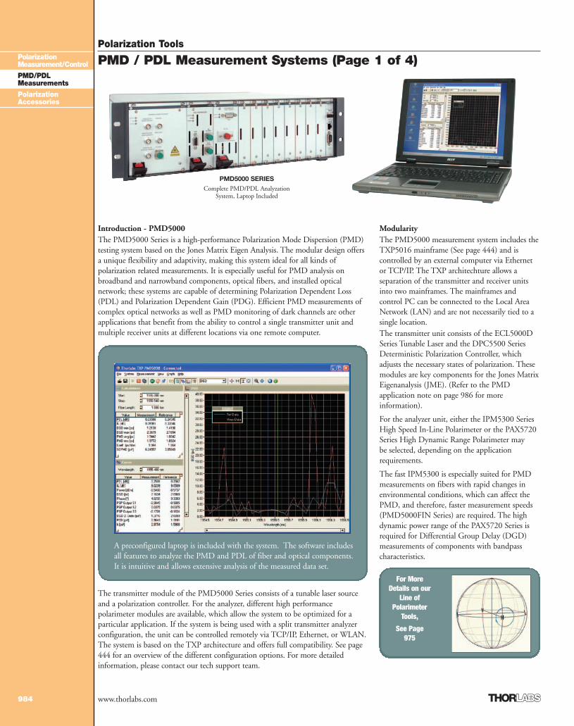
Introduction - PMD5000The PMD5000 Series is a high-performance Polarization Mode Dispersion (PMD)testing system based on the Jones Matrix Eigen Analysis. The modular design offersa unique flexibility and adaptivity, making this system ideal for all kinds ofpolarization related measurements. It is especially useful for PMD analysis on broadband and narrowband components, optical fibers, and installed opticalnetwork; these systems are capable of determining Polarization Dependent Loss(PDL) and Polarization Dependent Gain (PDG). Efficient PMD measurements ofcomplex optical networks as well as PMD monitoring of dark channels are otherapplications that benefit from the ability to control a single transmitter unit andmultiple receiver units at different locations via one remote computer.
The transmitter module of the PMD5000 Series consists of a tunable laser sourceand a polarization controller. For the analyzer, different high performancepolarimeter modules are available, which allow the system to be optimized for aparticular application. If the system is being used with a split transmitter analyzerconfiguration, the unit can be controlled remotely via TCP/IP, Ethernet, or WLAN.The system is based on the TXP architecture and offers full compatibility. See page444 for an overview of the different configuration options. For more detailedinformation, please contact our tech support team.
ModularityThe PMD5000 measurement system includes theTXP5016 mainframe (See page 444) and iscontrolled by an external computer via Ethernetor TCP/IP. The TXP architechture allows aseparation of the transmitter and receiver unitsinto two mainframes. The mainframes andcontrol PC can be connected to the Local AreaNetwork (LAN) and are not necessarily tied to asingle location.The transmitter unit consists of the ECL5000DSeries Tunable Laser and the DPC5500 SeriesDeterministic Polarization Controller, whichadjusts the necessary states of polarization. Thesemodules are key components for the Jones MatrixEigenanalysis (JME). (Refer to the PMDapplication note on page 986 for moreinformation).
For the analyzer unit, either the IPM5300 SeriesHigh Speed In-Line Polarimeter or the PAX5720Series High Dynamic Range Polarimeter may be selected, depending on the applicationrequirements.
The fast IPM5300 is especially suited for PMDmeasurements on fibers with rapid changes inenvironmental conditions, which can affect thePMD, and therefore, faster measurement speeds(PMD5000FIN Series) are required. The highdynamic power range of the PAX5720 Series isrequired for Differential Group Delay (DGD)measurements of components with bandpasscharacteristics.
A preconfigured laptop is included with the system. The software includesall features to analyze the PMD and PDL of fiber and optical components.It is intuitive and allows extensive analysis of the measured data set.
PMD5000 SERIESComplete PMD/PDL Analyzation
System, Laptop Included
For MoreDetails on our
Line ofPolarimeter
Tools,
See Page975
2_PMD-PDLMeas 984-987.qxd.P 7/13/07 1:24 PM Page 984
Polarization Tools
985
PolarizationMeasurement/Control
PMD/PDLMeasurements
PolarizationAccessories
www.thorlabs.com
PMD / PDL Measurement Systems (Page 2 of 4)
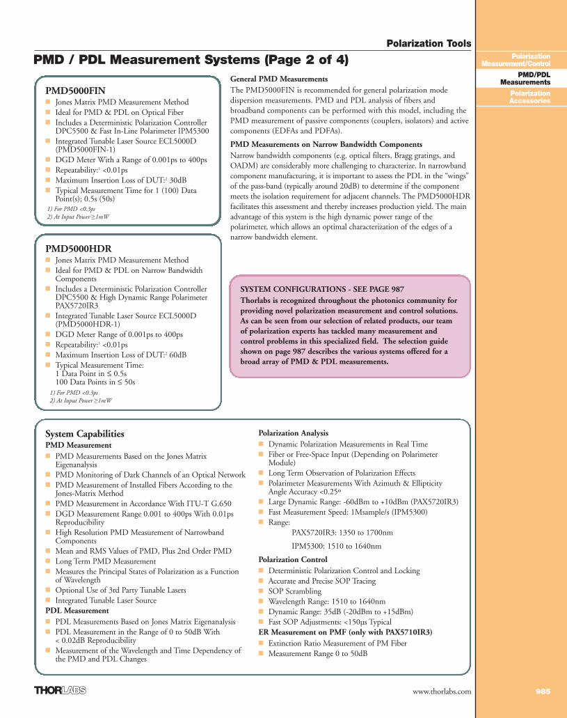
PMD5000FIN■ Jones Matrix PMD Measurement Method■ Ideal for PMD & PDL on Optical Fiber■ Includes a Deterministic Polarization Controller
DPC5500 & Fast In-Line Polarimeter IPM5300■ Integrated Tunable Laser Source ECL5000D
(PMD5000FIN-1)■ DGD Meter With a Range of 0.001ps to 400ps■ Repeatability:1 <0.01ps■ Maximum Insertion Loss of DUT:2 30dB■ Typical Measurement Time for 1 (100) Data
Point(s); 0.5s (50s)
PMD5000HDR■ Jones Matrix PMD Measurement Method■ Ideal for PMD & PDL on Narrow Bandwidth
Components■ Includes a Deterministic Polarization Controller
DPC5500 & High Dynamic Range PolarimeterPAX5720IR3
■ Integrated Tunable Laser Source ECL5000D(PMD5000HDR-1)
■ DGD Meter Range of 0.001ps to 400ps■ Repeatability:1 <0.01ps■ Maximum Insertion Loss of DUT:2 60dB■ Typical Measurement Time:
1 Data Point in ≤ 0.5s100 Data Points in ≤ 50s
SYSTEM CONFIGURATIONS - SEE PAGE 987Thorlabs is recognized throughout the photonics community forproviding novel polarization measurement and control solutions.As can be seen from our selection of related products, our teamof polarization experts has tackled many measurement andcontrol problems in this specialized field. The selection guideshown on page 987 describes the various systems offered for abroad array of PMD & PDL measurements.
General PMD MeasurementsThe PMD5000FIN is recommended for general polarization modedispersion measurements. PMD and PDL analysis of fibers andbroadband components can be performed with this model, including thePMD measurement of passive components (couplers, isolators) and activecomponents (EDFAs and PDFAs).
PMD Measurements on Narrow Bandwidth ComponentsNarrow bandwidth components (e.g. optical filters, Bragg gratings, andOADM) are considerably more challenging to characterize. In narrowbandcomponent manufacturing, it is important to assess the PDL in the “wings”of the pass-band (typically around 20dB) to determine if the componentmeets the isolation requirement for adjacent channels. The PMD5000HDRfacilitates this assessment and thereby increases production yield. The mainadvantage of this system is the high dynamic power range of thepolarimeter, which allows an optimal characterization of the edges of anarrow bandwidth element.
System CapabilitiesPMD Measurement■ PMD Measurements Based on the Jones Matrix
Eigenanalysis■ PMD Monitoring of Dark Channels of an Optical Network■ PMD Measurement of Installed Fibers According to the
Jones-Matrix Method■ PMD Measurement in Accordance With ITU-T G.650■ DGD Measurement Range 0.001 to 400ps With 0.01ps
Reproducibility■ High Resolution PMD Measurement of Narrowband
Components■ Mean and RMS Values of PMD, Plus 2nd Order PMD■ Long Term PMD Measurement ■ Measures the Principal States of Polarization as a Function
of Wavelength■ Optional Use of 3rd Party Tunable Lasers■ Integrated Tunable Laser SourcePDL Measurement■ PDL Measurements Based on Jones Matrix Eigenanalysis■ PDL Measurement in the Range of 0 to 50dB With
< 0.02dB Reproducibility■ Measurement of the Wavelength and Time Dependency of
the PMD and PDL Changes
Polarization Analysis■ Dynamic Polarization Measurements in Real Time■ Fiber or Free-Space Input (Depending on Polarimeter
Module)■ Long Term Observation of Polarization Effects■ Polarimeter Measurements With Azimuth & Ellipticity
Angle Accuracy <0.25º■ Large Dynamic Range: -60dBm to +10dBm (PAX5720IR3)■ Fast Measurement Speed: 1Msample/s (IPM5300)■ Range:
PAX5720IR3: 1350 to 1700nm
IPM5300: 1510 to 1640nm
Polarization Control■ Deterministic Polarization Control and Locking■ Accurate and Precise SOP Tracing■ SOP Scrambling■ Wavelength Range: 1510 to 1640nm■ Dynamic Range: 35dB (-20dBm to +15dBm)■ Fast SOP Adjustments: <150µs TypicalER Measurement on PMF (only with PAX5710IR3)■ Extinction Ratio Measurement of PM Fiber■ Measurement Range 0 to 50dB
1) For PMD <0.3ps2) At Input Power ≥1mW
1) For PMD <0.3ps2) At Input Power ≥1mW
2_PMD-PDLMeas 984-987.qxd.P 7/13/07 1:24 PM Page 985
Polarization Tools
986
PolarizationMeasurement/Control
PMD/PDLMeasurements
PolarizationAccessories
www.thorlabs.com
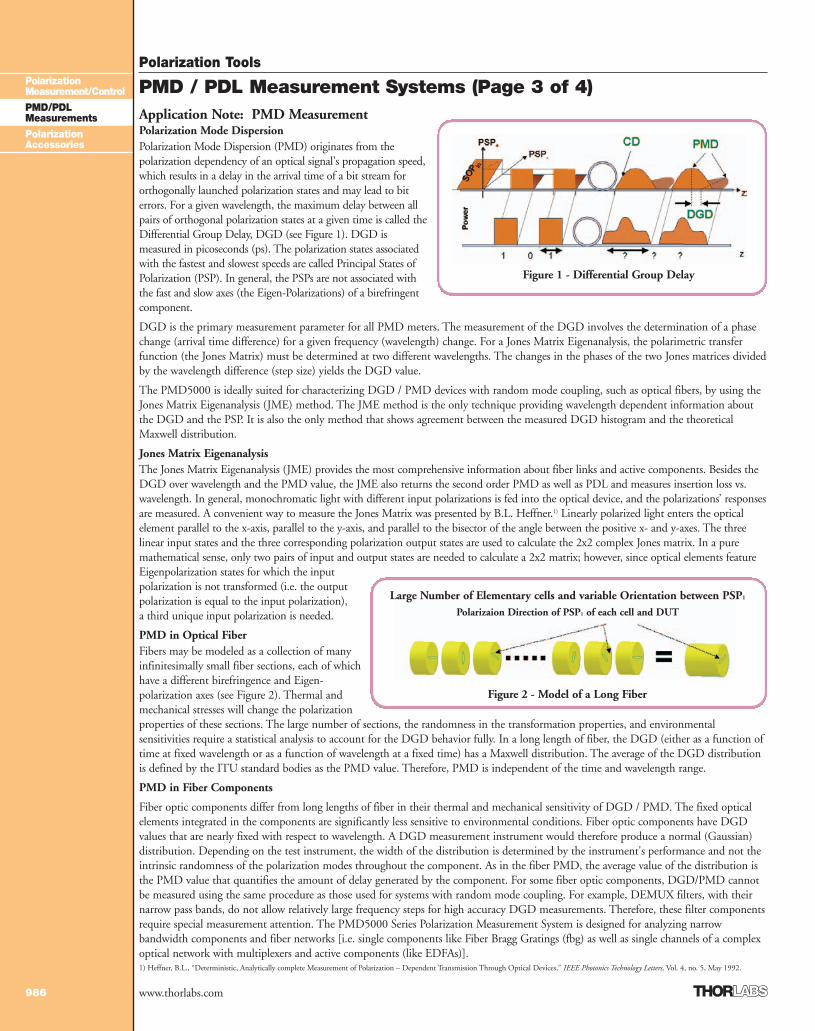
Application Note: PMD Measurement Polarization Mode DispersionPolarization Mode Dispersion (PMD) originates from thepolarization dependency of an optical signal's propagation speed,which results in a delay in the arrival time of a bit stream fororthogonally launched polarization states and may lead to biterrors. For a given wavelength, the maximum delay between allpairs of orthogonal polarization states at a given time is called theDifferential Group Delay, DGD (see Figure 1). DGD ismeasured in picoseconds (ps). The polarization states associatedwith the fastest and slowest speeds are called Principal States ofPolarization (PSP). In general, the PSPs are not associated withthe fast and slow axes (the Eigen-Polarizations) of a birefringentcomponent.
DGD is the primary measurement parameter for all PMD meters. The measurement of the DGD involves the determination of a phasechange (arrival time difference) for a given frequency (wavelength) change. For a Jones Matrix Eigenanalysis, the polarimetric transferfunction (the Jones Matrix) must be determined at two different wavelengths. The changes in the phases of the two Jones matrices dividedby the wavelength difference (step size) yields the DGD value.
The PMD5000 is ideally suited for characterizing DGD / PMD devices with random mode coupling, such as optical fibers, by using theJones Matrix Eigenanalysis (JME) method. The JME method is the only technique providing wavelength dependent information aboutthe DGD and the PSP. It is also the only method that shows agreement between the measured DGD histogram and the theoreticalMaxwell distribution.
Jones Matrix EigenanalysisThe Jones Matrix Eigenanalysis (JME) provides the most comprehensive information about fiber links and active components. Besides theDGD over wavelength and the PMD value, the JME also returns the second order PMD as well as PDL and measures insertion loss vs.wavelength. In general, monochromatic light with different input polarizations is fed into the optical device, and the polarizations’ responsesare measured. A convenient way to measure the Jones Matrix was presented by B.L. Heffner.1) Linearly polarized light enters the opticalelement parallel to the x-axis, parallel to the y-axis, and parallel to the bisector of the angle between the positive x- and y-axes. The threelinear input states and the three corresponding polarization output states are used to calculate the 2x2 complex Jones matrix. In a puremathematical sense, only two pairs of input and output states are needed to calculate a 2x2 matrix; however, since optical elements featureEigenpolarization states for which the inputpolarization is not transformed (i.e. the outputpolarization is equal to the input polarization),a third unique input polarization is needed.
PMD in Optical FiberFibers may be modeled as a collection of manyinfinitesimally small fiber sections, each of whichhave a different birefringence and Eigen-polarization axes (see Figure 2). Thermal andmechanical stresses will change the polarizationproperties of these sections. The large number of sections, the randomness in the transformation properties, and environmentalsensitivities require a statistical analysis to account for the DGD behavior fully. In a long length of fiber, the DGD (either as a function oftime at fixed wavelength or as a function of wavelength at a fixed time) has a Maxwell distribution. The average of the DGD distributionis defined by the ITU standard bodies as the PMD value. Therefore, PMD is independent of the time and wavelength range.
PMD in Fiber Components
Fiber optic components differ from long lengths of fiber in their thermal and mechanical sensitivity of DGD / PMD. The fixed opticalelements integrated in the components are significantly less sensitive to environmental conditions. Fiber optic components have DGDvalues that are nearly fixed with respect to wavelength. A DGD measurement instrument would therefore produce a normal (Gaussian)distribution. Depending on the test instrument, the width of the distribution is determined by the instrument's performance and not theintrinsic randomness of the polarization modes throughout the component. As in the fiber PMD, the average value of the distribution isthe PMD value that quantifies the amount of delay generated by the component. For some fiber optic components, DGD/PMD cannotbe measured using the same procedure as those used for systems with random mode coupling. For example, DEMUX filters, with theirnarrow pass bands, do not allow relatively large frequency steps for high accuracy DGD measurements. Therefore, these filter componentsrequire special measurement attention. The PMD5000 Series Polarization Measurement System is designed for analyzing narrowbandwidth components and fiber networks [i.e. single components like Fiber Bragg Gratings (fbg) as well as single channels of a complexoptical network with multiplexers and active components (like EDFAs)].
Figure 2 - Model of a Long Fiber
Figure 1 - Differential Group Delay
PMD / PDL Measurement Systems (Page 3 of 4)
1) Heffner, B.L., “Deterministic, Analytically complete Measurement of Polarization – Dependent Transmission Through Optical Devices,” IEEE Photonics Technology Letters, Vol. 4, no. 5, May 1992.
Large Number of Elementary cells and variable Orientation between PSP1
Polarizaion Direction of PSP1 of each cell and DUT
2_PMD-PDLMeas 984-987.qxd.P 7/13/07 1:25 PM Page 986
Polarization Tools
987
PolarizationMeasurement/Control
PMD/PDLMeasurements
PolarizationAccessories
www.thorlabs.com
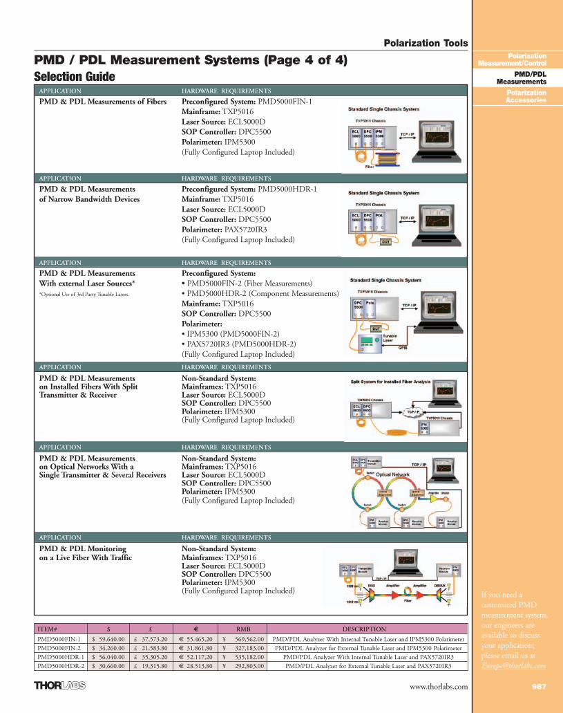
Selection GuideAPPLICATION HARDWARE REQUIREMENTS
PMD & PDL Measurements of Fibers Preconfigured System: PMD5000FIN-1Mainframe: TXP5016Laser Source: ECL5000DSOP Controller: DPC5500Polarimeter: IPM5300(Fully Configured Laptop Included)
APPLICATION HARDWARE REQUIREMENTS
PMD & PDL Measurements Preconfigured System: PMD5000HDR-1of Narrow Bandwidth Devices Mainframe: TXP5016
Laser Source: ECL5000DSOP Controller: DPC5500Polarimeter: PAX5720IR3(Fully Configured Laptop Included)
APPLICATION HARDWARE REQUIREMENTS
PMD & PDL Measurements Preconfigured System:With external Laser Sources* • PMD5000FIN-2 (Fiber Measurements)*Optional Use of 3rd Party Tunable Lasers. • PMD5000HDR-2 (Component Measurements)
Mainframe: TXP5016SOP Controller: DPC5500Polarimeter:• IPM5300 (PMD5000FIN-2)• PAX5720IR3 (PMD5000HDR-2)(Fully Configured Laptop Included)
APPLICATION HARDWARE REQUIREMENTS
PMD & PDL Measurements Non-Standard System:on Installed Fibers With Split Mainframes: TXP5016 Transmitter & Receiver Laser Source: ECL5000D
SOP Controller: DPC5500Polarimeter: IPM5300(Fully Configured Laptop Included)
APPLICATION HARDWARE REQUIREMENTS
PMD & PDL Measurements Non-Standard System:on Optical Networks With a Mainframes: TXP5016Single Transmitter & Several Receivers Laser Source: ECL5000D
SOP Controller: DPC5500Polarimeter: IPM5300(Fully Configured Laptop Included)
APPLICATION HARDWARE REQUIREMENTS
PMD & PDL Monitoring Non-Standard System:on a Live Fiber With Traffic Mainframes: TXP5016
Laser Source: ECL5000D SOP Controller: DPC5500Polarimeter: IPM5300 (Fully Configured Laptop Included) If you need a
customized PMDmeasurement system,our engineers areavailable to discussyour application;please email us [email protected]
ITEM# $ £ € RMB DESCRIPTION
PMD5000FIN-1 $ 59,640.00 £ 37,573.20 € 55.465,20 ¥ 569,562.00 PMD/PDL Analyzer With Internal Tunable Laser and IPM5300 PolarimeterPMD5000FIN-2 $ 34,260.00 £ 21,583.80 € 31.861,80 ¥ 327,183.00 PMD/PDL Analyzer for External Tunable Laser and IPM5300 PolarimeterPMD5000HDR-1 $ 56,040.00 £ 35,305.20 € 52.117,20 ¥ 535,182.00 PMD/PDL Analyzer With Internal Tunable Laser and PAX5720IR3 PMD5000HDR-2 $ 30,660.00 £ 19,315.80 € 28.513,80 ¥ 292,803.00 PMD/PDL Analyzer for External Tunable Laser and PAX5720IR3
PMD / PDL Measurement Systems (Page 4 of 4)
2_PMD-PDLMeas 984-987.qxd.P 7/13/07 1:25 PM Page 987
Polarization Accessories
988
PolarizationMeasurement/Control
PMD/PDLMeasurements
PolarizationAccessories
www.thorlabs.com
Achromatic Wave Plates
Mounted Achromatic Wave Plates
GLAN-LASERPrism Polarizers10mm x 10mm Aperture
See Page 816
RELATED PRODUCT
ACHROMATIC ACHROMATICQuarter-Wave Plate Half-Wave Plate $ £ € RMB DESCRIPTION
AQWP05M-630 AHWP05M-630 $ 780.00 £ 491.40 € 725,40 ¥ 7,449.00 450-800nmAQWP05M-950 AHWP05M-950 $ 780.00 £ 491.40 € 725,40 ¥ 7,449.00 690-1200nmAQWP05M-1430 AHWP05M-1430 $ 780.00 £ 491.40 € 725,40 ¥ 7,449.00 1200-1650nm
Specifications■ Substrate Material: Crystalline
Quartz & Magnesium Fluoride■ Diameter:
12.7mm ±0.1mm Unmounted25.4mm Mounted
■ Retardance Accuracy (typ):<λ/150 RMS Over Spectral Range
■ Beam Deviation: <10arcsec
■ Transmitted Wavefront Error:<λ/4
■ Clear Aperture: Ø0.38" (Ø9.6mm)
■ Surface Quality: 40-20 Scratch-Dig
■ Reflectance: <0.5% Per Surface■ Damage Limit:
2J/cm2 @ 10ns 1.064µm
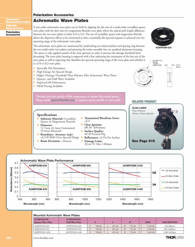
Achromatic Wave Plate Performance
Ret
ard
ance
(Wav
es)
Thorlabs provides quality OEM components at volume discounted prices.Please email: [email protected] to request a quote specific to your needs.
AQWP05M-630
A zero-order achromatic wave plate can be built by aligning the fast axis of a multi-order crystalline quartzwave plate with the slow axis of a magnesium fluoride wave plate where the optical path length differencebetween the two wave plates is either λ/4 or λ/2. The use of crystalline quartz and magnesium fluorideallows the dispersive effects to be minimized so that a nominally flat spectral response is achieved over theoperating range of the achromatic wave plate.
The achromatic wave plates are constructed by sandwiching an etched stainless steel spacing ring betweenthe two multi-order wave plates and epoxying the entire assembly into an anodized aluminum housing.The epoxy is only applied outside of the clear aperture in order to prevent the damage threshold fromdecreasing. The wave plate housing is engraved with a line indicating the orientation of the fast axis of thewave plate as well as engraving that identifies the spectral operating range of the wave plate and whether itis a λ/4 or λ/2 wave plate.
■ Spectrally Flat Retardance■ High Energy Air-Spaced Design■ Higher Damage Threshold Than Polymer Film Achromatic Wave Plates■ Quarter- and Half-Wave Available■ Improved IR Performance■ OEM Pricing Available
3_PolarizAccess 988-994.qxd.P 7/13/07 2:54 PM Page 988
Polarization Accessories
989
PolarizationMeasurement/Control
PMD/PDLMeasurements
PolarizationAccessories
www.thorlabs.com
Zero-Order Wave Plates
Mounted Zero-Order WavePlatesQUARTER-WAVE PLATE HALF-WAVE PLATEITEM# ITEM# $ £ € RMB COATING
WPQ05M-266 WPH05M-266 $ 407.00 £ 256.40 € 378,50 ¥ 3,886.90 AR Coated 266nmWPQ05M-308 WPH05M-308 $ 407.00 £ 256.40 € 378,50 ¥ 3,886.90 AR Coated 308nmWPQ05M-355 WPH05M-355 $ 407.00 £ 256.40 € 378,50 ¥ 3,886.90 AR Coated 355nmWPQ05M-488 WPH05M-488 $ 407.00 £ 256.40 € 378,50 ¥ 3,886.90 AR Coated 488nmWPQ05M-514 WPH05M-514 $ 407.00 £ 256.40 € 378,50 ¥ 3,886.90 AR Coated 514nmWPQ05M-532 WPH05M-532 $ 407.00 £ 256.40 € 378,50 ¥ 3,886.90 AR Coated 532nmWPQ05M-546 WPH05M-546 $ 407.00 £ 256.40 € 378,50 ¥ 3,886.90 AR Coated 546nmWPQ05M-633 WPH05M-633 $ 407.00 £ 256.40 € 378,50 ¥ 3,886.90 AR Coated 633nmWPQ05M-670 WPH05M-670 $ 407.00 £ 256.40 € 378,50 ¥ 3,886.90 AR Coated 670nmWPQ05M-780 WPH05M-780 $ 407.00 £ 256.40 € 378,50 ¥ 3,886.90 AR Coated 780nmWPQ05M-808 WPH05M-808 $ 407.00 £ 256.40 € 378,50 ¥ 3,886.90 AR Coated 808nmWPQ05M-830 WPH05M-830 $ 407.00 £ 256.40 € 378,50 ¥ 3,886.90 AR Coated 830nmWPQ05M-980 WPH05M-980 $ 407.00 £ 256.40 € 378,50 ¥ 3,886.90 AR Coated 980nmWPQ05M-1053 WPH05M-1053 $ 407.00 £ 256.40 € 378,50 ¥ 3,886.90 AR Coated 1053nmWPQ05M-1064 WPH05M-1064 $ 407.00 £ 256.40 € 378,50 ¥ 3,886.90 AR Coated 1064nmWPQ05M-1310 WPH05M-1310 $ 407.00 £ 256.40 € 378,50 ¥ 3,886.90 AR Coated 1310nmWPQ05M-1550 WPH05M-1550 $ 407.00 £ 256.40 € 378,50 ¥ 3,886.90 AR Coated 1550nm
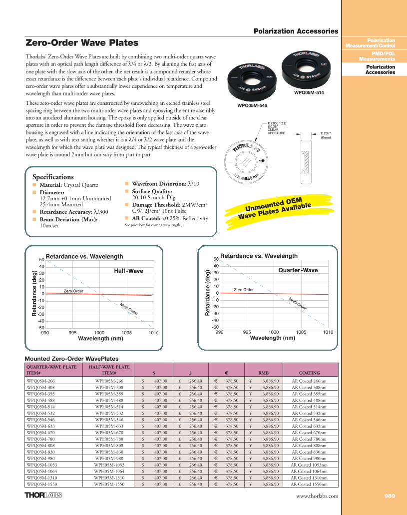
Thorlabs' Zero-Order Wave Plates are built by combining two multi-order quartz waveplates with an optical path length difference of λ/4 or λ/2. By aligning the fast axis ofone plate with the slow axis of the other, the net result is a compound retarder whoseexact retardance is the difference between each plate's individual retardence. Compoundzero-order wave plates offer a substantially lower dependence on temperature andwavelength than multi-order wave plates.
These zero-order wave plates are constructed by sandwiching an etched stainless steelspacing ring between the two multi-order wave plates and epoxying the entire assemblyinto an anodized aluminum housing. The epoxy is only applied outside of the clearaperture in order to prevent the damage threshold from decreasing. The wave platehousing is engraved with a line indicating the orientation of the fast axis of the waveplate, as well as with text stating whether it is a λ/4 or λ/2 wave plate and thewavelength for which the wave plate was designed. The typical thickness of a zero-orderwave plate is around 2mm but can vary from part to part.
-Wave -Wave
Specifications■ Material: Crystal Quartz■ Diameter:
12.7mm ±0.1mm Unmounted25.4mm Mounted
■ Retardance Accuracy: λ/300■ Beam Deviation (Max):
10arcsec
■ Wavefront Distortion: λ/10■ Surface Quality:
20-10 Scratch-Dig■ Damage Threshold: 2MW/cm2
CW, 2J/cm2 10ns Pulse■ AR Coated: <0.25% ReflectivitySee price box for coating wavelengths.
0.237"(6mm)
WPQ05M-546
WPQ05M-514
Unmounted OEM
Wave Plates Available
3_PolarizAccess 988-994.qxd.P 7/13/07 2:54 PM Page 989
Polarization Accessories
990
PolarizationMeasurement/Control
PMD/PDLMeasurements
PolarizationAccessories
www.thorlabs.com
Multi-Order Wave Plates
Specifications■ Material: Crystal Quartz■ Diameter:
12.7mm +0.00/-0.01Unmounted25.4mm Mounted
■ Retardation: λ/200
■ Wavefront Distortion: λ/10■ Surface Quality:
10-5 Scratch-Dig■ Damage Threshold: 2MW/cm2
CW, 2J/cm2 10ns Pulse■ AR Coated: <0.25% ReflectivitySee price box for coating wavelengths.Thorlabs' multi-order wave plates are made
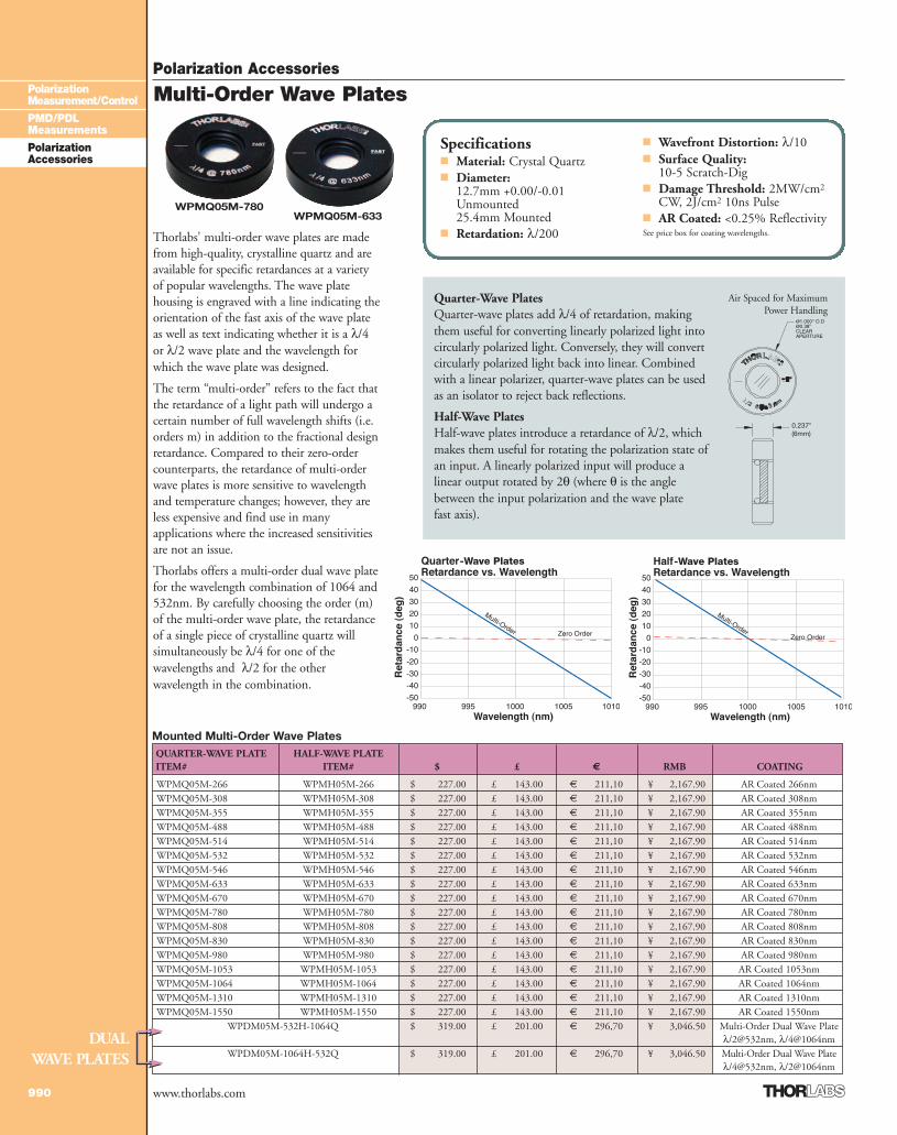
from high-quality, crystalline quartz and areavailable for specific retardances at a varietyof popular wavelengths. The wave platehousing is engraved with a line indicating theorientation of the fast axis of the wave plateas well as text indicating whether it is a λ/4or λ/2 wave plate and the wavelength forwhich the wave plate was designed.
The term “multi-order” refers to the fact thatthe retardance of a light path will undergo acertain number of full wavelength shifts (i.e.orders m) in addition to the fractional designretardance. Compared to their zero-ordercounterparts, the retardance of multi-orderwave plates is more sensitive to wavelengthand temperature changes; however, they areless expensive and find use in manyapplications where the increased sensitivitiesare not an issue.
Thorlabs offers a multi-order dual wave platefor the wavelength combination of 1064 and532nm. By carefully choosing the order (m)of the multi-order wave plate, the retardanceof a single piece of crystalline quartz willsimultaneously be λ/4 for one of thewavelengths and λ/2 for the otherwavelength in the combination.
Mounted Multi-Order Wave PlatesQUARTER-WAVE PLATE HALF-WAVE PLATEITEM# ITEM# $ £ € RMB COATING
WPMQ05M-266 WPMH05M-266 $ 227.00 £ 143.00 € 211,10 ¥ 2,167.90 AR Coated 266nmWPMQ05M-308 WPMH05M-308 $ 227.00 £ 143.00 € 211,10 ¥ 2,167.90 AR Coated 308nmWPMQ05M-355 WPMH05M-355 $ 227.00 £ 143.00 € 211,10 ¥ 2,167.90 AR Coated 355nmWPMQ05M-488 WPMH05M-488 $ 227.00 £ 143.00 € 211,10 ¥ 2,167.90 AR Coated 488nmWPMQ05M-514 WPMH05M-514 $ 227.00 £ 143.00 € 211,10 ¥ 2,167.90 AR Coated 514nmWPMQ05M-532 WPMH05M-532 $ 227.00 £ 143.00 € 211,10 ¥ 2,167.90 AR Coated 532nmWPMQ05M-546 WPMH05M-546 $ 227.00 £ 143.00 € 211,10 ¥ 2,167.90 AR Coated 546nmWPMQ05M-633 WPMH05M-633 $ 227.00 £ 143.00 € 211,10 ¥ 2,167.90 AR Coated 633nmWPMQ05M-670 WPMH05M-670 $ 227.00 £ 143.00 € 211,10 ¥ 2,167.90 AR Coated 670nmWPMQ05M-780 WPMH05M-780 $ 227.00 £ 143.00 € 211,10 ¥ 2,167.90 AR Coated 780nmWPMQ05M-808 WPMH05M-808 $ 227.00 £ 143.00 € 211,10 ¥ 2,167.90 AR Coated 808nmWPMQ05M-830 WPMH05M-830 $ 227.00 £ 143.00 € 211,10 ¥ 2,167.90 AR Coated 830nmWPMQ05M-980 WPMH05M-980 $ 227.00 £ 143.00 € 211,10 ¥ 2,167.90 AR Coated 980nmWPMQ05M-1053 WPMH05M-1053 $ 227.00 £ 143.00 € 211,10 ¥ 2,167.90 AR Coated 1053nmWPMQ05M-1064 WPMH05M-1064 $ 227.00 £ 143.00 € 211,10 ¥ 2,167.90 AR Coated 1064nmWPMQ05M-1310 WPMH05M-1310 $ 227.00 £ 143.00 € 211,10 ¥ 2,167.90 AR Coated 1310nmWPMQ05M-1550 WPMH05M-1550 $ 227.00 £ 143.00 € 211,10 ¥ 2,167.90 AR Coated 1550nm
WPDM05M-532H-1064Q $ 319.00 £ 201.00 € 296,70 ¥ 3,046.50 Multi-Order Dual Wave Plateλ/2@532nm, λ/4@1064nm
WPDM05M-1064H-532Q $ 319.00 £ 201.00 € 296,70 ¥ 3,046.50 Multi-Order Dual Wave Plateλ/4@532nm, λ/2@1064nm
Quarter-Wave PlatesQuarter-wave plates add λ/4 of retardation, makingthem useful for converting linearly polarized light intocircularly polarized light. Conversely, they will convertcircularly polarized light back into linear. Combinedwith a linear polarizer, quarter-wave plates can be usedas an isolator to reject back reflections.
Half-Wave PlatesHalf-wave plates introduce a retardance of λ/2, whichmakes them useful for rotating the polarization state ofan input. A linearly polarized input will produce alinear output rotated by 2θ (where θ is the anglebetween the input polarization and the wave plate fast axis).
-Wave Plates -Wave Plates
DUALWAVE PLATES
Air Spaced for MaximumPower Handling
0.237"(6mm)
WPMQ05M-780WPMQ05M-633
3_PolarizAccess 988-994.qxd.P 7/13/07 2:54 PM Page 990
Polarization Accessories
991
PolarizationMeasurement/Control
PMD/PDLMeasurements
PolarizationAccessories
www.thorlabs.com
WollastonPrisms
Double Glan-TaylorPolarizers
Wire GridPolarizers
RELATED PRODUCTSRELATED PRODUCTSFor More Complete Selection of our POLARIZATION OPTICS See Pages 809-824For More Complete Selection of our POLARIZATION OPTICS See Pages 809-824
See Page818
See Page817
See Page820
Telecom Wave Plates
Specifications■ Material: Crystalline Quartz■ Size (mm):
2.0 x 2.0 or 5.0 x 5.0■ Retardance Accuracy: λ/500■ Flatness: λ/10
■ Surface Quality: 10-5 Scratch-Dig
■ Parallelism: 10arcsec■ Damage Threshold: 2MW/cm2
CW, 2 J/cm2 10ns YAG Pulse■ AR Coated:
R < 0.25% Reflectivity
ITEM# $ £ € RMB THICKNESS DESCRIPTION
WPQ201 $ 62.00 £ 39.10 € 57,70 ¥ 592.10 137µm Quarter-Wave Plate, 1550nm Center Wavelength, 2mm Sq.WPH202 $ 62.00 £ 39.10 € 57,70 ¥ 592.10 91µm Half-Wave Plate, 1550nm Center Wavelength, 2mm Sq.WPQ501 $ 82.00 £ 51.70 € 76,30 ¥ 783.10 137µm Quarter-Wave Plate, 1550nm Center Wavelength, 5mm Sq.WPH502 $ 82.00 £ 51.70 € 76,30 ¥ 783.10 91µm Half-Wave Plate, 1550nm Center Wavelength, 5mm Sq.
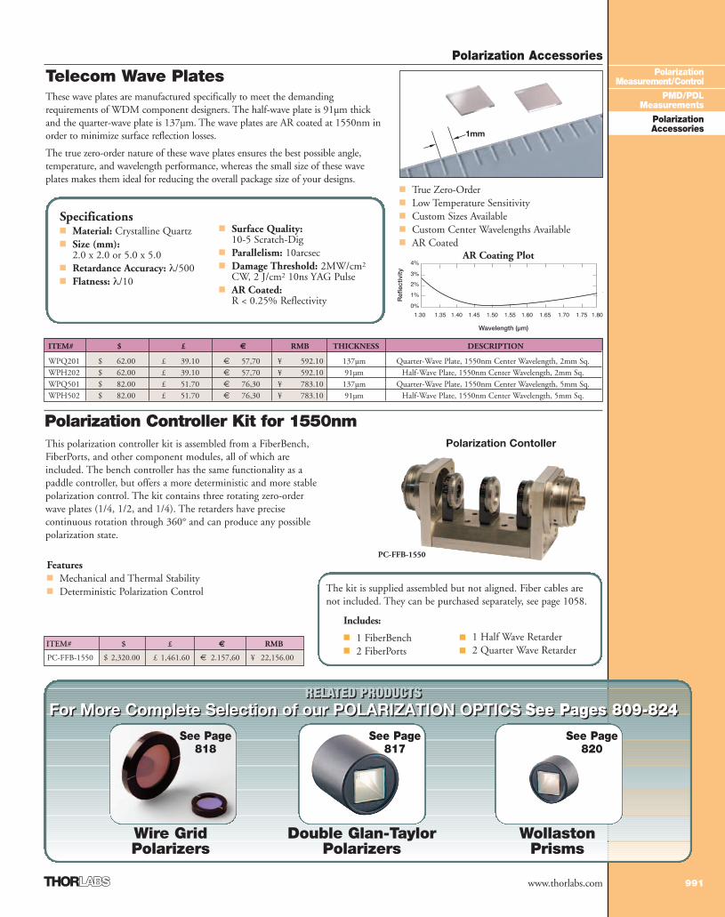
These wave plates are manufactured specifically to meet the demandingrequirements of WDM component designers. The half-wave plate is 91µm thickand the quarter-wave plate is 137µm. The wave plates are AR coated at 1550nm inorder to minimize surface reflection losses.
The true zero-order nature of these wave plates ensures the best possible angle,temperature, and wavelength performance, whereas the small size of these waveplates makes them ideal for reducing the overall package size of your designs.
Wavelength (µm)
Ref
lect
ivity
■ True Zero-Order■ Low Temperature Sensitivity■ Custom Sizes Available■ Custom Center Wavelengths Available■ AR Coated
AR Coating Plot
1mm
Polarization Controller Kit for 1550nmThis polarization controller kit is assembled from a FiberBench,FiberPorts, and other component modules, all of which areincluded. The bench controller has the same functionality as apaddle controller, but offers a more deterministic and more stablepolarization control. The kit contains three rotating zero-orderwave plates (1/4, 1/2, and 1/4). The retarders have precisecontinuous rotation through 360° and can produce any possiblepolarization state.
Includes:
■ 1 FiberBench■ 2 FiberPorts
ITEM# $ £ € RMB
PC-FFB-1550 $ 2,320.00 £ 1,461.60 € 2.157,60 ¥ 22,156.00
Features■ Mechanical and Thermal Stability ■ Deterministic Polarization Control
Polarization Contoller
PC-FFB-1550
The kit is supplied assembled but not aligned. Fiber cables arenot included. They can be purchased separately, see page 1058.
■ 1 Half Wave Retarder■ 2 Quarter Wave Retarder
3_PolarizAccess 988-994.qxd.P 7/19/07 5:51 PM Page 991
Polarization Accessories
992
PolarizationMeasurement/Control
PMD/PDLMeasurements
PolarizationAccessories
www.thorlabs.com
Polarization Accessories
992
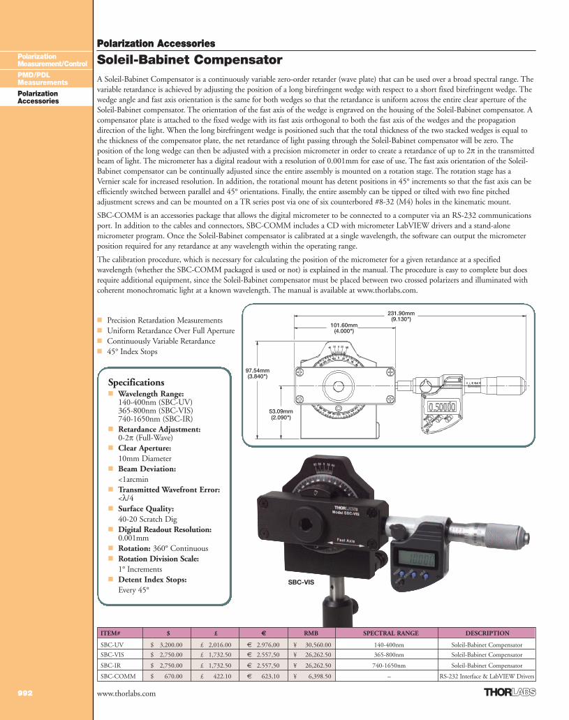
A Soleil-Babinet Compensator is a continuously variable zero-order retarder (wave plate) that can be used over a broad spectral range. Thevariable retardance is achieved by adjusting the position of a long birefringent wedge with respect to a short fixed birefringent wedge. Thewedge angle and fast axis orientation is the same for both wedges so that the retardance is uniform across the entire clear aperture of theSoleil-Babinet compensator. The orientation of the fast axis of the wedge is engraved on the housing of the Soleil-Babinet compensator. Acompensator plate is attached to the fixed wedge with its fast axis orthogonal to both the fast axis of the wedges and the propagationdirection of the light. When the long birefringent wedge is positioned such that the total thickness of the two stacked wedges is equal tothe thickness of the compensator plate, the net retardance of light passing through the Soleil-Babinet compensator will be zero. Theposition of the long wedge can then be adjusted with a precision micrometer in order to create a retardance of up to 2� in the transmittedbeam of light. The micrometer has a digital readout with a resolution of 0.001mm for ease of use. The fast axis orientation of the Soleil-Babinet compensator can be continually adjusted since the entire assembly is mounted on a rotation stage. The rotation stage has aVernier scale for increased resolution. In addition, the rotational mount has detent positions in 45° increments so that the fast axis can beefficiently switched between parallel and 45° orientations. Finally, the entire assembly can be tipped or tilted with two fine pitchedadjustment screws and can be mounted on a TR series post via one of six counterbored #8-32 (M4) holes in the kinematic mount.
SBC-COMM is an accessories package that allows the digital micrometer to be connected to a computer via an RS-232 communicationsport. In addition to the cables and connectors, SBC-COMM includes a CD with micrometer LabVIEW drivers and a stand-alonemicrometer program. Once the Soleil-Babinet compensator is calibrated at a single wavelength, the software can output the micrometerposition required for any retardance at any wavelength within the operating range.
The calibration procedure, which is necessary for calculating the position of the micrometer for a given retardance at a specifiedwavelength (whether the SBC-COMM packaged is used or not) is explained in the manual. The procedure is easy to complete but doesrequire additional equipment, since the Soleil-Babinet compensator must be placed between two crossed polarizers and illuminated withcoherent monochromatic light at a known wavelength. The manual is available at www.thorlabs.com.
■ Precision Retardation Measurements■ Uniform Retardance Over Full Aperture■ Continuously Variable Retardance■ 45° Index Stops
Soleil-Babinet Compensator
Specifications■ Wavelength Range:
140-400nm (SBC-UV)365-800nm (SBC-VIS)740-1650nm (SBC-IR)
■ Retardance Adjustment:0-2� (Full-Wave)
■ Clear Aperture: 10mm Diameter
■ Beam Deviation: <1arcmin
■ Transmitted Wavefront Error:<λ/4
■ Surface Quality: 40-20 Scratch Dig
■ Digital Readout Resolution:0.001mm
■ Rotation: 360° Continuous■ Rotation Division Scale:
1° Increments■ Detent Index Stops:
Every 45°
ITEM# $ £ € RMB SPECTRAL RANGE DESCRIPTION
SBC-UV $ 3,200.00 £ 2,016.00 € 2.976,00 ¥ 30,560.00 140-400nm Soleil-Babinet Compensator
SBC-VIS $ 2,750.00 £ 1,732.50 € 2.557,50 ¥ 26,262.50 365-800nm Soleil-Babinet Compensator
SBC-IR $ 2,750.00 £ 1,732.50 € 2.557,50 ¥ 26,262.50 740-1650nm Soleil-Babinet Compensator
SBC-COMM $ 670.00 £ 422.10 € 623,10 ¥ 6,398.50 – RS-232 Interface & LabVIEW Drivers
SBC-VIS
(4.000")101.60mm
(9.130")231.90mm
(2.090")53.09mm
(3.840")97.54mm
3_PolarizAccess 988-994.qxd.P 7/13/07 2:55 PM Page 992
Polarization Accessories
993
PolarizationMeasurement/Control
PMD/PDLMeasurements
PolarizationAccessories
www.thorlabs.com
Polarization Accessories
993
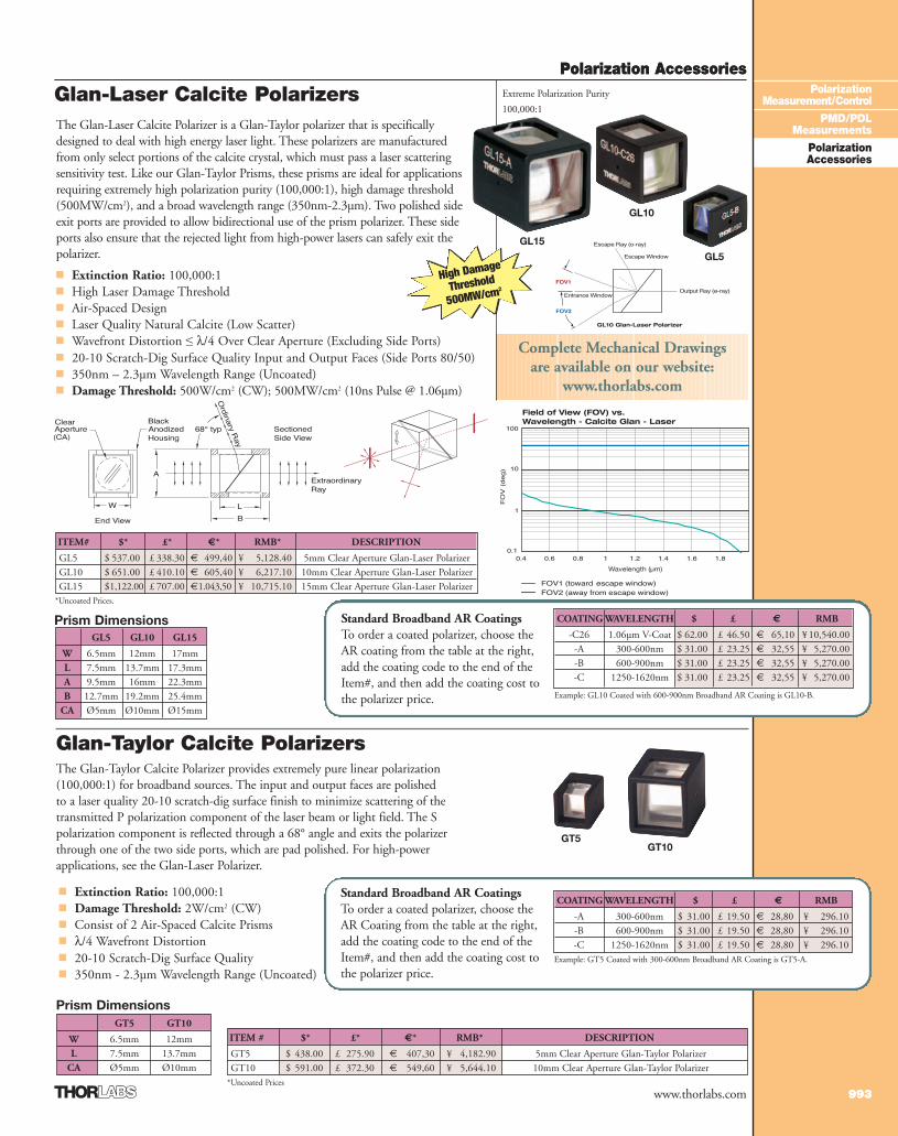
Glan-Laser Calcite Polarizers
Prism DimensionsGT5 GT10
W 6.5mm 12mmL 7.5mm 13.7mm
CA Ø5mm Ø10mm
■ Extinction Ratio: 100,000:1■ Damage Threshold: 2W/cm2 (CW)■ Consist of 2 Air-Spaced Calcite Prisms■ λ/4 Wavefront Distortion■ 20-10 Scratch-Dig Surface Quality■ 350nm - 2.3µm Wavelength Range (Uncoated)
The Glan-Taylor Calcite Polarizer provides extremely pure linear polarization(100,000:1) for broadband sources. The input and output faces are polishedto a laser quality 20-10 scratch-dig surface finish to minimize scattering of thetransmitted P polarization component of the laser beam or light field. The Spolarization component is reflected through a 68° angle and exits the polarizerthrough one of the two side ports, which are pad polished. For high-powerapplications, see the Glan-Laser Polarizer.
ITEM # $* £* €* RMB* DESCRIPTION
GT5 $ 438.00 £ 275.90 € 407,30 ¥ 4,182.90 5mm Clear Aperture Glan-Taylor PolarizerGT10 $ 591.00 £ 372.30 € 549,60 ¥ 5,644.10 10mm Clear Aperture Glan-Taylor Polarizer
The Glan-Laser Calcite Polarizer is a Glan-Taylor polarizer that is specificallydesigned to deal with high energy laser light. These polarizers are manufacturedfrom only select portions of the calcite crystal, which must pass a laser scatteringsensitivity test. Like our Glan-Taylor Prisms, these prisms are ideal for applicationsrequiring extremely high polarization purity (100,000:1), high damage threshold(500MW/cm2), and a broad wavelength range (350nm-2.3µm). Two polished sideexit ports are provided to allow bidirectional use of the prism polarizer. These sideports also ensure that the rejected light from high-power lasers can safely exit thepolarizer.
■ Extinction Ratio: 100,000:1 ■ High Laser Damage Threshold■ Air-Spaced Design■ Laser Quality Natural Calcite (Low Scatter)■ Wavefront Distortion ≤ λ/4 Over Clear Aperture (Excluding Side Ports)■ 20-10 Scratch-Dig Surface Quality Input and Output Faces (Side Ports 80/50)■ 350nm – 2.3µm Wavelength Range (Uncoated)■ Damage Threshold: 500W/cm2 (CW); 500MW/cm2 (10ns Pulse @ 1.06µm)
Prism DimensionsGL5 GL10 GL15
W 6.5mm 12mm 17mmL 7.5mm 13.7mm 17.3mmA 9.5mm 16mm 22.3mmB 12.7mm 19.2mm 25.4mm
CA Ø5mm Ø10mm Ø15mm
ITEM# $* £* €* RMB* DESCRIPTION
GL5 $ 537.00 £ 338.30 € 499,40 ¥ 5,128.40 5mm Clear Aperture Glan-Laser PolarizerGL10 $ 651.00 £ 410.10 € 605,40 ¥ 6,217.10 10mm Clear Aperture Glan-Laser PolarizerGL15 $1,122.00 £ 707.00 €1.043,50 ¥ 10,715.10 15mm Clear Aperture Glan-Laser Polarizer
Field of View (FOV) vs.Wavelength - Calcite Glan - Laser
Wavelength (µm)
GL10 Glan-Laser Polarizer
Glan-Taylor Calcite Polarizers
*Uncoated Prices.
Complete Mechanical Drawingsare available on our website:
www.thorlabs.com
COATING WAVELENGTH $ £ € RMB
-C26 1.06µm V-Coat $ 62.00 £ 46.50 € 65,10 ¥ 10,540.00-A 300-600nm $ 31.00 £ 23.25 € 32,55 ¥ 5,270.00-B 600-900nm $ 31.00 £ 23.25 € 32,55 ¥ 5,270.00-C 1250-1620nm $ 31.00 £ 23.25 € 32,55 ¥ 5,270.00
Example: GL10 Coated with 600-900nm Broadband AR Coating is GL10-B.
Standard Broadband AR Coatings To order a coated polarizer, choose theAR coating from the table at the right,add the coating code to the end of theItem#, and then add the coating cost tothe polarizer price.
COATING WAVELENGTH $ £ € RMB
-A 300-600nm $ 31.00 £ 19.50 € 28,80 ¥ 296.10-B 600-900nm $ 31.00 £ 19.50 € 28,80 ¥ 296.10-C 1250-1620nm $ 31.00 £ 19.50 € 28,80 ¥ 296.10
Example: GT5 Coated with 300-600nm Broadband AR Coating is GT5-A.
Standard Broadband AR Coatings To order a coated polarizer, choose theAR Coating from the table at the right,add the coating code to the end of theItem#, and then add the coating cost tothe polarizer price.
High Damage
Threshold
500MW/cm2
GT5 GT10
*Uncoated Prices
GL5
GL10
GL15
Extreme Polarization Purity
100,000:1
3_PolarizAccess 988-994.qxd.P 7/13/07 2:56 PM Page 993
Polarization Accessories
994
PolarizationMeasurement/Control
PMD/PDLMeasurements
PolarizationAccessories
www.thorlabs.com
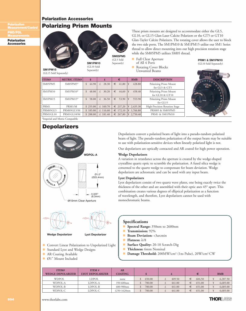
These prism mounts are designed to accommodate either the GL5,GL10, or GL15 Glan-Laser Calcite Polarizers or the GT5 or GT10Glan-Tayler Calcite Polarizers. The rotating cover allows the user to blockthe two side ports. The SM1PM10 & SM1PM15 utilize our SM1 Seriesthread to allow direct mounting into our high precision rotation stagewhile the SM05PM5 utilizes SM05 thread.
■ Full Clear Apertureof All 4 Ports
■ Rotating Cover BlocksUnwanted Beams
ITEM# METRIC ITEM# $ £ € RMB DESCRIPTION
SM05PM5 SM05PM5* $ 44.90 £ 28.30 € 41,80 ¥ 428.80 Polarizing Prism Mountfor GL5 & GT5
SM1PM10 SM1PM10* $ 48.00 £ 30.20 € 44,60 ¥ 458.40 Polarizing Prism Mountfor GL10 & GT10
SM1PM15 SM1PM15* $ 58.00 £ 36.50 € 53,90 ¥ 553.90 Polarizing Prism Mountfor GL15
PRM1 PRM1/M $ 255.00 £ 160.70 € 237,20 ¥ 2,435.30 High-Precision Rotation StagePRM05GL5 PRM05GL5/M $ 185.00 £ 116.60 € 172,10 ¥ 1,766.80 PRM05 & SM05PM5PRM1GL10 PRM1GL10/M $ 288.00 £ 181.40 € 267,80 ¥ 2,750.40 PRM1 & SM1PM10
PRM1 & SM1PM10 (GL10 Sold Separately)
Polarizing Prism Mounts
SM1PM15(GL15 Sold Separately)
SM1PM10(GL10 SoldSeparately)
SM05PM5(GL5 SoldSeparately)
DepolarizersDepolarizers convert a polarized beam of light into a pseudo-random polarizedbeam of light. The pseudo-random polarization of the output beam may be suitableto use with polarization-sensitive devices when linearly polarized light is not.
Our depolarizers are optically contacted and AR coated for high power operation.
Wedge DepolarizersA variation in retardance across the aperture is created by the wedge-shapedcrystalline quartz optic to scramble the polarization. A fused silica wedge iscemented to the quartz wedge to compensate for beam deviation. Wedgedepolarizers are achromatic and can be used with any input beam.
Lyot DepolarizersLyot depolarizers consist of two quartz wave plates, one being exactly twice thethickness of the other and are assembled with their optic axes 45° apart. Thiscombination creates various degrees of elliptical polarization as a functionof wavelength, and therefore, Lyot depolarizers cannot be used withmonochromatic beams.
Wedge Depolarizer Lyot Depolarizer
■ Convert Linear Polarization to Unpolarized Light■ Standard Lyot and Wedge Designs■ AR Coating Available■ Ø1" Mount Included
Specifications■ Spectral Range: 350nm to 2600nm■ Transmission: 92%■ Beam Deviation: <3arcmin■ Flatness: λ/8■ Surface Quality: 20-10 Scratch-Dig■ Thickness: 6mm Nominal■ Damage Threshold: 200MW/cm2 (1ns Pulse), 20W/cm2 CW
ITEM# ITEM # ARWEDGE DEPOLARIZER LYOT DEPOLARIZER COATING $ £ € RMB
WDPOL LDPOL none $ 650.00 £ 409.50 € 604,50 ¥ 6,207.50WDPOL-A LDPOL-A 350-600nm $ 700.00 £ 441.00 € 651,00 ¥ 6,685.00WDPOL-B LDPOL-B 600-900nm $ 700.00 £ 441.00 € 651,00 ¥ 6,685.00WDPOL-C LDPOL-C 1250-1620nm $ 700.00 £ 441.00 € 651,00 ¥ 6,685.00
*Imperial and Metric Compatible
WDPOL-A
3_PolarizAccess 988-994.qxd.P 7/13/07 2:56 PM Page 994
Top Related