


Languages
Pages
Legal

Assets Delivery Group Infrastructure Design Branch
PIPELINE SELECTION GUIDELINES
Selection Criteria for Pipe, Pipe Fittings and Interconnection with
New and Legacy Corporation Pipelines
VERSION 1
REVISION 0
APRIL 2017

Pipeline Selection Guidelines
Selection Criteria for Pipe, Pipe Fittings and Interconnection with New and Legacy Corporation Pipelines
Uncontrolled if Printed Page 2 of 63 Ver 1 Rev 0
© Copyright – Water Corporation 2017
FOREWORD
The intent of Design Standards and associated Guidance Manuals is to specify requirements, related guidance and
information that assure effective design and delivery of fit for purpose Water Corporation infrastructure assets for
best whole-of-life value with least risk to Corporation service standards and safety. Design standards and Guidance
Manuals are intended to promote uniformity of approach by asset designers, drafters and constructors to the design,
construction, commissioning and delivery of water infrastructure and to the compatibility of new infrastructure
with existing like infrastructure.
Design Standards and Guidance Manuals draw on the asset design, management and field operational experience
gained and documented by the Corporation and by the water industry generally over time. They are intended for
application by Corporation staff, designers, constructors and land developers to the planning, design, construction
and commissioning of Corporation infrastructure including water services provided by land developers for takeover
by the Corporation.
Nothing in this Guidance Manual diminishes the responsibility of designers and constructors for applying the
requirements of WA OSH Regulations 1996 (Division 12, Construction Industry – consultation on hazards and
safety management) to the delivery of Corporation assets. Information on these statutory requirements may be
viewed at the following web site location:
http://www.commerce.wa.gov.au/WorkSafe/Content/Industries/Construction/Further_information/National_standard_for_construction.html
Enquiries and informed feedback relating to the technical content of this Guidance Manual should be directed to
the Principal Engineers, Wastewater and Conveyance Sections, Infrastructure Design Branch. Future changes to the
Guidance Manual will be notified to registered users as and when published.
Manager, Infrastructure Design Branch
This document is prepared without the assumption of a duty of care by the Water Corporation. The document is not intended
to be nor should it be relied on as a substitute for professional engineering design expertise or any other professional advice.
Users should use and reference the current version of this document.
© Copyright – Water Corporation: This standard and software is copyright. With the exception of use permitted by the
Copyright Act 1968, no part may be reproduced without the written permission of the Water Corporation.

Pipeline Selection Guidelines
Selection Criteria for Pipe, Pipe Fittings and Interconnection with New and Legacy Corporation Pipelines
Uncontrolled if Printed Page 3 of 63
Ver 1Rev 0
© Copyright Water Corporation 2017
DISCLAIMER
This Guidance Manual is intended solely for application to the acquisition of water infrastructure in Operating
Areas in Western Australia where the Water Corporation has been licensed to provide water services subject to the
terms and conditions of its Operating License.
This Manual is provided for application by a suitably qualified professional design engineer who applies the skill,
knowledge and experience necessary to understand the risks involved and undertake all infrastructure, selection
design and installation specification preparation work.
Any interpretation of anything in this Manual that deviates from the requirements specified in a project design brief
drawing, construction specification or in design process requirements should be resolved by reference to and
determination by the design engineer.
The Corporation accepts no liability for any loss or damage that arises from anything in the Manual including loss
or damage that may arise due to the errors and omissions of any person.

Pipeline Selection Guidelines
Selection Criteria for Pipe, Pipe Fittings and Interconnection with New and Legacy Corporation Pipelines
Uncontrolled if Printed Page 4 of 63
Ver 1Rev 0
© Copyright Water Corporation 2017
REVISION STATUS
The revision status of this manual is shown section by section below:
REVISION STATUS
SECT. VER./
REV.
DATE PAGES
REVISED
REVISION DESCRIPTION
(Section, Clause, Sub-Clause)
RVWD. APRV.
1 1/0 20.04. 17 All New Version/Revision KR KP
2 1/0 20.04. 17 All New Version/Revision KR KP
3 1/0 20.04. 17 All New Version/Revision KR KP
4 1/0 20.04. 17 All New Version/Revision KR KP
Pipeline Selection Guidelines
Selection Criteria for Pipe, Pipe Fittings and Interconnection with New and Legacy Corporation Pipelines
Uncontrolled if Printed Page 5 of 63
Ver 1Rev 0
© Copyright Water Corporation 2017
PIPELINE SELECTION GUIDELINES Selection Criteria for Pipe, Pipe Fittings and Interconnection with
New and Legacy Corporation Pipelines
CONTENTS Section Page
1 PURPOSE AND SCOPE .............................................................................................................. 7
1.1 Purpose .......................................................................................................................................... 7
1.2 Scope .............................................................................................................................................. 7
2 REFERENCED DOCUMENTS .................................................................................................. 7
2.1 Corporation Design Standards ................................................................................................... 7
2.2 Industry Standards and Guidelines ............................................................................................ 9
2.3 Product Specifications ............................................................................................................... 10
2.4 Strategic Products Register ....................................................................................................... 13
3 LEGACY PIPELINE CHARACTERISTICS .......................................................................... 14
4 APPLICATION BY DESIGNERS ............................................................................................ 14
4.1 Pipeline Selection Considerations ............................................................................................. 15 4.1.1 Material and Application Comparison ......................................................................................... 15
4.1.2 Trenchless Application Comparison ............................................................................................ 20
4.2 Flexible Pipe Characteristics ..................................................................................................... 23 Table 4.2 - Indicative Characteristics of Plastics Pressure Pipes
4, 5, 6, 7 ............................................................. 23
Table 4.3 – Indicative Characteristics of MSCL Pipe ...................................................................................... 25
Table 4.4 – Indicative Characteristics of DICL Pipe ........................................................................................ 26
4.3 Asset Performance Requirements ............................................................................................ 27 4.3.1 Material and Engineering Properties ............................................................................................ 27
4.3.2 Location and Environment ........................................................................................................... 27
4.3.3 System Pressure Constraints and Re-rating ................................................................................. 28
4.3.4 Field Testing ................................................................................................................................ 28
4.3.5 Pipeline System Inter-connectibility ............................................................................................ 29
4.3.6 System Accessibility, Safety, Operability and Maintainability ................................................... 29
4.4 Design Selection Justification .................................................................................................... 30 Table 4.5 - Pressure Re-rating Design Factors for Plastics & Metallic Pipes
9, 10, 11 ......................................... 31
Table 4.6 - Pressure Pipeline System Inter-connectibility ................................................................................ 33
Table 4.7 - Non-pressure Pipeline System Inter-connectibility ........................................................................ 33

Pipeline Selection Guidelines
Selection Criteria for Pipe, Pipe Fittings and Interconnection with New and Legacy Corporation Pipelines
Uncontrolled if Printed Page 6 of 63
Ver 1Rev 0
© Copyright Water Corporation 2017
APPENDIX A .................................................................................................................................................. 35
Table A1 Pipeline Material, Engineering and Jointing Characteristics ............................................... 35
Table A2 Pipeline Longevity, Installation and Testing Characteristics18
............................................. 39
APPENDIX B .................................................................................................................................................. 42
Table B1 Typical Outside Diameter Dimension Data for CIOD and Metric Pipe (DN 50 - 900) ........ 42
APPENDIX C LEGACY PIPELINE CHARACTERISTICS .............................................................. 45
C1 General ........................................................................................................................................ 45
C2 Cast Iron ..................................................................................................................................... 45
C3 Asbestos Cement ........................................................................................................................ 46
C4 Steel ............................................................................................................................................. 47 C4.1 Mains ............................................................................................................................................ 47
C4.2 Services ........................................................................................................................................ 47
C4.3 Stainless Steel .............................................................................................................................. 48
C5 Concrete ...................................................................................................................................... 48
C6 Vitrified Clay .............................................................................................................................. 48
C7 Plastics ......................................................................................................................................... 49 C7.1 Polyethylene ................................................................................................................................. 49
C7.2 PVC .............................................................................................................................................. 49
C7.3 GRP .............................................................................................................................................. 50
APPENDIX D .................................................................................................................................................. 51
Table D1 Steel Pipes - Dimensions (Vintage 1975 to Current) ............................................................... 51
Table D2 Steel Pipes - Dimensions & Weight (Vintage pre-1975) .......................................................... 55
APPENDIX E .................................................................................................................................................. 59
Table E1 Reinforced Concrete Pressure Pipe - Dimensions - MWSS & DD ....................................... 59
Table E2 RC Pressure Pipe Dimensions - Humes Ltd ............................................................................ 60
APPENDIX F .................................................................................................................................................. 61
Table F1 Standard Asbestos Cement Pipes 1959 to 1981 ....................................................................... 61
Table F2 Maximum Working Pressures for Special Asbestos Cement Pipe ........................................ 62
Pipeline Selection Guidelines
Selection Criteria for Pipe, Pipe Fittings and Interconnection with New and Legacy Corporation Pipelines
Uncontrolled if Printed Page 7 of 63
Ver 1Rev 0
© Copyright Water Corporation 2017
1 Purpose and Scope
1.1 Purpose
The purpose of this Manual is to provide guidance to designers and specifiers of pipeline infrastructure
systems to be owned, operated and maintained by the Corporation and to designers and specifiers of
pipeline systems to be taken over by the Corporation in accordance with agreed business processes
and commercial arrangements.
1.2 Scope
This Manual is intended to provide information and guidance on conveyance pipeline system
characteristics, selection criteria, usage constraints and limitations in one place. This is aimed at
selecting pipeline system components that are best for Corporation business, having due regard to:
Material, size, engineering performance and in-service performance;
Market availability in the desired sizes and quantities, compatibility with new and legacy pipelines
and ready availability of pipeline spares and repair components for all pipeline applications;
Optimal whole of asset and service life value for money.
Constructability, operability, maintainability and longevity performance in Western Australia;
Timely establishment of the pipeline requirements baseline to be delivered throughout pipeline
project planning, design, installation, commissioning and hand over to operators.
The Manual includes references to recognised design, material, product and related installation
standards and specifications that are acceptable to the Corporation, as asset owner and operator. Its
coverage references physical, longevity and installability performance characteristics for many pipe
materials - including some that are neither preferred nor authorised for general use at present. These
include, for example, ABS and DI pipes. The guidance provided is intended to enable comparison of
performance characteristics across a broad range of preferred and non-preferred pipe materials covered
by current Australian pipe manufacturing standards. The Manual references the Strategic Products
Register where commonly used pipe and pipe fitting brands have been listed as authorised for use, on
the basis of compliance with Corporation business requirements.
Any perceived conflict between information or guidance in the Manual and requirements mandated in
currently published Design Standards should be referred to the appropriate project Design Manager for
clarification.
2 Referenced Documents The Corporation has documented engineering and operational performance requirements for its
strategic infrastructure in a suite of engineering standards and product specifications, based on over a
century of service experience in the water industry. These are subject to periodic review and change -
including the addition of new standards and specifications - from time to time in accordance with best
for business priorities.
Corporation project planners, designers and specifiers should make application for access to the
published standards and product specifications that are referenced in project documents as being
relevant to project scope. Formal access should be on the basis of legitimate involvement in
Corporation capital, operational and land development infrastructure projects. Applicants should liaise
with project design managers to ensure that applications for access to particular
standards/specifications are appropriate to the particular project to be delivered.
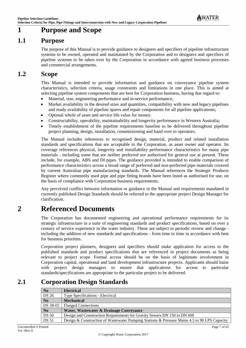
2.1 Corporation Design Standards
No Electrical
DS 26 Type Specifications - Electrical
No Mechanical
DS 38-02 Flanged Connections
No Water, Wastewater & Drainage Conveyance
DS 50 Design and Construction Requirements for Gravity Sewers DN 150 to DN 600
DS 51 Design & Construction of Wastewater Pumping Stations & Pressure Mains 4.5 to 90 LPS Capacity

Pipeline Selection Guidelines
Selection Criteria for Pipe, Pipe Fittings and Interconnection with New and Legacy Corporation Pipelines
Uncontrolled if Printed Page 8 of 63
Ver 1Rev 0
© Copyright Water Corporation 2017
DS 53 Vacuum Sewerage Standard
DS 60 Water Supply Distribution Standard - Pipelines Other Than Reticulation
DS 63 Water Reticulation Pipelines DN 250 and Smaller
DS 63-01 Water Reticulation Standard - Supplement - Dual Water Supply Systems
DS 65 Pipe Fittings Standard Drawings
DS 66 Urban Main Drainage Standard
DS 101 Asset Identification and Pipeline Warning Signage
No Safety
S151 Prevention of Falls
DS 100 Suspended Flooring (Grid Mesh and Chequer Plate)
SPN 1 Strategic Practice Note - Reinforced Concrete Practice
No Drafting
DS 80 WCX CAD Standard
No Welding & Corrosion Prevention
WS-1 Metal Arc Welding
WS-2 Welding Joining Specification Thermoplastics
DS 91 Selection, Design and Monitoring of Cathodic Protection (CP) Systems
DS 95 Standard for the selection , preparation, application, inspection and testing of Protective Coatings
on Water Corporation Assets
Sub-ref. Description of Surface Preparation & Protective Coating Specifications (DS 95 Table 5)
A1 Surface Preparation for the Application of Protective Coatings on Steel or Cast Iron
A2 Surface Preparation for the Application of Protective Coatings on Stainless Steel
A3 Surface Preparation for the Application of Protective Coatings on Galvanised Steel
A4 Surface Preparation for the Application of Protective Coatings on Aluminium
A5 Surface Preparation for the Application of Protective Coating on Concrete
A6 Surface Preparation for the Application of Protective Coating on Plastics
A7 Surface Preparation for the Application of Protective Coating on Fusion Bonded Polyethylene (e.g.
Sintakote®)
B1 Inorganic Zinc Silicate Coating on Steel or Cast Iron
B2 Inorganic Zinc Silicate, Epoxy Primer Tie-Coat, Acrylic top Coating on Steel or Cast Iron
C1 Zinc Rich Epoxy primer Coating on Steel or Cast Iron
C2 Zinc Rich Epoxy primer Epoxy Mastic Coat, Polyurethane top Coat on Steel or Cast Iron
C3 Zinc Rich Epoxy primer Epoxy Mastic Coat, on Steel or Cast Iron
C4 Zinc Rich Epoxy primer , Polyurethane top Coat on Steel or Cast Iron
D1 High Build Epoxy Coating on Steel or Cast Iron
D2 High Build Epoxy Coating on Butterfly Valves
D3 High Build Epoxy Coating on New Old Concrete
E1 Epoxy Mastic Coating on Steel or Cast Iron
E2 Epoxy Mastic Coating on Non-Return, Control Valves (New & Existing Valves)
E3 Epoxy Mastic Polyurethane top Coat on Steel or Cast Iron
E4 Epoxy Mastic Polyurethane top Coat on Galvanised Steel
E5 Epoxy Mastic Polyurethane top Coat on Fusion Bonded Polyethylene (Sintakote)
F1 Glass Flake Epoxy Mastic Coating
F2 High Build Ceramic Filled Epoxy Coating on Existing Control Valves
F3 High Build Ceramic Filled Epoxy Coating on New and Existing Pumps
G1 Thermostatically Applied Polyester Powder Coating for Aluminium Sheet Metal Cabinets
G2 Thermal Bonded Polymeric Coating on Valves and Fittings for Water Industry Purposes
H1 Repair of Galvanised Coating
H2 Galvanised Coating of Steel Structures
I1 Elastomeric Polyurethane Protective Coating on Concrete
J1 Anti-Graffiti Coating on New and Old Steel Structures
J2 Anti-Graffiti Coating on New and Old Concrete Structures
K1 Aesthetic Finish Coating on above Ground PVC Pipes and Fittings
L1 Tape Wrapping Procedure
L2 Heat Shrink Sleeve
M1 Coating Procedure for Pipe Transition (Below to Above Ground)
M2 Coating Procedure for Sintakote Pipe and Steel Pipe Joints
M3 Coating Procedure for Clean Skin Pipe Permanently Exposed to Atmosphere
M4 Coating Procedure for Coupling Jointed Pipes
M5 Coating Procedure for Steel Pipe at the Concrete Interface

Pipeline Selection Guidelines
Selection Criteria for Pipe, Pipe Fittings and Interconnection with New and Legacy Corporation Pipelines
Uncontrolled if Printed Page 9 of 63
Ver 1Rev 0
© Copyright Water Corporation 2017
M6 Coating Procedure for Sintakote Pipe at the Concrete Interface
M7 Coating Procedure on galvanised steel for the decorative purposes
M8 Cement Mortar Lining Requirement
2.2 Industry Standards and Guidelines
No Plastics Industry Pipe Association (PIPA) Guidelines
POP001 Electrofusion Jointing of PE Pipe and Fittings for Pressure Applications
POP002 Polyethylene (PE) Pipes and Fittings for Compressed Air
POP003 Butt Fusion Jointing of PE Pipes and Fittings - Recommended Parameters
POP004 Polyethylene Pipe and Fittings Compounds
POP004A Supplementary List - Materials Specific to Electrofusion and Moulded Fittings
POP005 Packaging, Handling and Storage of Polyethylene Pipes and Fittings
POP006 Derating Requirements for Fittings (Manufactured Polyethylene Pipe Fittings)
POP007 Metal Backing Flanges for use With Polyethylene (PE) Pipe Flange Adaptors
POP008 Striping of Polyolefin Pipes
POP009 Polyethylene Rural and Flood Pipe
POP010A Part 1: Polyethylene Pressure Pipes Design for Dynamic Stresses
POP010B Part 2: Fusion Fittings for use With Polyethylene Pressure Pipes Design for Dynamic Stresses
POP011 AS/NZS 5065 Polyethylene (PE) and Polypropylene (PP) Pipes & Fittings for Drainage and
Sewerage Applications has replaced POP011
POP013 Temperature Rerating of PE Pipes
POP014 Assessment of Polyethylene Welds
POP015 Design Guidance for Polypropylene Structured Wall Pipes
POP101 PVC Pressure Pipes Design for Dynamic Stresses
POP102 Solvent Cement Jointing of PVC Pipe
POP103 Depth of Engagement for PVC Pipes
POP104 PVC Pipe Equivalence
POP105 PVC Pipes In Bore Casings
POP106 Verification Guidelines for Best Environmental Practice PVC Pipe and Fittings
POP107 Measuring the PVC content in PVC pipes and fittings
POP201 Resistance of Plastics Pipes and Fittings to Water and Wastewater Chemicals
POP202 PVC and PE Pressure Pipe Installation on Curved Alignments
POP203 Identification of Buried Pipe Systems
POP204 Expected Service Life of Elastomeric Pipe Seals
POP205 Water Jet Cleaning of Plastics Pipes
POP206 Thermal Insulation of Hot Water Pipes for Plumbing Applications
POP207 Installation of Potable Watermains In Contaminated Ground
No Technical Information
TC4130 AS/NZS 4130 Polyethylene Pipes (PE) for Pressure Applications
No Technical Manuals
TM001 PE Pipe System Maintenance Guide
TM002 PVC Pressure Pipe System Maintenance Guide
No Technical Note
TN001 Electrofusion Jointing of Polyethylene (PE) Pipe and Fittings for Pressure Applications
TN002 Weathering of PE Pipes
TN003 Temperature Derating of PVC Pipes for Pressure Applications
TN004 Polyethylene - The Optimum Gas Material?
TN005 Notes on Field Pressure Testing
TN006 Weathering of PVC Pipes and Fittings
TN007 PVC and Polyethylene Pipe Systems for Food Transport Applications
TN008 Chlorine Dioxide Disinfectant for Drinking Water – Effect on Pipe and Seal Materials
TN009 Field Butt Welding of Rural Or Thin Wall Poly Pipe
TN010 Explanation of Material / SDR Relationship
TN011 Polyethylene Compressed Air Pipe Guidance Note
TN012 PVC Pipes At Low Operating Temperatures
TN013 Life Expectancy for Plastics Pipes
TN014 PVC Tops Pipe Joints Performance Test
TN015 Modified PVC Pressure Pipes
TN016 Non Destructive Examination of PE Welds - Emerging Techniques

Pipeline Selection Guidelines
Selection Criteria for Pipe, Pipe Fittings and Interconnection with New and Legacy Corporation Pipelines
Uncontrolled if Printed Page 10 of 63
Ver 1Rev 0
© Copyright Water Corporation 2017
No Technical Papers
TP001 PVC Technical Information (Resistance of elastomeric seal pipe joints to tree root penetration)
TP002 Pipeline Replacement Using Relining
TP003 Specifying Butt Welding of Polyethylene Pipe Systems
TP004 Plastics Pipe In Water and Waste Water infrastructure
TP005 Flexible Pipe Design
TP006 Long Term Performance of PVC Pressure Pipe
No Test Method
SM001 Method for Assessing The Resin Dispersion In PVC Pipes
SM002 Low Pressure Air Testing of Pipelines
No Other Information
N/A Polyethylene for Horizontal Directional Drilling Published by The Plastics Pipe Institute (USA)
N/A History of Plastics Pipe Systems In Australia
No WSAA Water Industry Standards
WSA 113 Reinforced Concrete Pipes with Flexible Thermoplastic Linings
WSA 115 Post-Formed Variable Bend PVC Fittings for Non-Pressure Pipelines (Refer DS 50)
WSA 117 ABS Compounds, Pipes and Fittings for Water Supply and Sewerage (non-preferred at present)
No WSAA Technical Notes
WSA-TN1 PE squeeze-off
WSA-TN2 Guidelines for the use of non-metallic pipes with ductile iron elastomeric joint fittings and
interactive spreadsheet calculator
WSA-TN3 Guidelines for the pipe ring bending stiffness and allowable deflection of ductile iron pipe
WSA-TN4 Guidelines for design of pressure pipeline systems for water supply using PVC-M and PVC-O
pipes.
WSA-TN5 Guidelines for installation of pressure pipe systems for water supply using PVC-M and PVC-O
pipes
WSA-TN6 Guidelines for the use of cement mortar linings in sewerage applications
WSA-TN7 Guidelines for Pressure Pipeline Data Cleansing
WSA-TN8 Assessing the Likelihood of Aqueous Corrosion
WSAA Terminology Reference
TP001 Pipeline Acronyms and Classifications Guideline
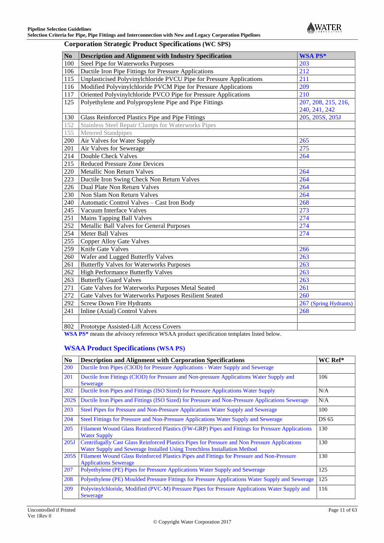
2.3 Product Specifications
Corporation Strategic Product Specifications (SPS) detail the minimum product engineering, supply,
quality assurance and compliance performance characteristics required to deliver Corporation water
infrastructure at least whole-of-life cost and least risk to service standards and safety. Many Strategic
Product Specifications align generally with published WSAA product performance specification
templates for water supply and sewerage network infrastructure components.
WSAA Product Specification templates are typically based on water industry product fitness-for-
purpose and risk criteria and on recognised Australian and international standards. Adapting WSAA
Product Specification templates to Corporation applications requires incorporation of Corporation
stakeholder agreed configuration options and commercial compliance requirements to assure sound
business outcomes, where proposed for use in project procurement and contractual documents.
Product specifications provide a documented performance specification baseline for:
Procurement of manufactured products and materials for water supply and sewerage networks;
Reference in project installation and construction specifications and tender documents;
Evaluating/auditing compliance of strategic branded products with Corporation performance
requirements and authorisation of compliant products in the Strategic Products Register.
Currently published Strategic Product Specifications are listed below for reference. WSAA Product
Specifications are also listed as potential templates for developing specifications for products not
currently covered by Corporation Strategic Product Specifications, by agreement with the Corporation.
Pipeline Selection Guidelines
Selection Criteria for Pipe, Pipe Fittings and Interconnection with New and Legacy Corporation Pipelines
Uncontrolled if Printed Page 11 of 63
Ver 1Rev 0
© Copyright Water Corporation 2017
Corporation Strategic Product Specifications (WC SPS)
No Description and Alignment with Industry Specification WSA PS*
100 Steel Pipe for Waterworks Purposes 203
106 Ductile Iron Pipe Fittings for Pressure Applications 212
115 Unplasticised Polyvinylchloride PVCU Pipe for Pressure Applications 211
116 Modified Polyvinylchloride PVCM Pipe for Pressure Applications 209
117 Oriented Polyvinylchloride PVCO Pipe for Pressure Applications 210
125 Polyethylene and Polypropylene Pipe and Pipe Fittings 207, 208, 215, 216,
240, 241, 242
130 Glass Reinforced Plastics Pipe and Pipe Fittings 205, 205S, 205J
152 Stainless Steel Repair Clamps for Waterworks Pipes
155 Metered Standpipes
200 Air Valves for Water Supply 265
201 Air Valves for Sewerage 275
214 Double Check Valves 264
215 Reduced Pressure Zone Devices
220 Metallic Non Return Valves 264
223 Ductile Iron Swing Check Non Return Valves 264
226 Dual Plate Non Return Valves 264
230 Non Slam Non Return Valves 264
240 Automatic Control Valves – Cast Iron Body 268
245 Vacuum Interface Valves 273
251 Mains Tapping Ball Valves 274
252 Metallic Ball Valves for General Purposes 274
254 Meter Ball Valves 274
255 Copper Alloy Gate Valves
259 Knife Gate Valves 266
260 Wafer and Lugged Butterfly Valves 263
261 Butterfly Valves for Waterworks Purposes 263
262 High Performance Butterfly Valves 263
263 Butterfly Guard Valves 263
271 Gate Valves for Waterworks Purposes Metal Seated 261
272 Gate Valves for Waterworks Purposes Resilient Seated 260
292 Screw Down Fire Hydrants 267 (Spring Hydrants)
241 Inline (Axial) Control Valves 268
802 Prototype Assisted-Lift Access Covers WSA PS* means the advisory reference WSAA product specification templates listed below.
WSAA Product Specifications (WSA PS)
No Description and Alignment with Corporation Specifications WC Ref* 200 Ductile Iron Pipes (CIOD) for Pressure Applications - Water Supply and Sewerage
201 Ductile Iron Fittings (CIOD) for Pressure and Non-pressure Applications Water Supply and
Sewerage
106
202 Ductile Iron Pipes and Fittings (ISO Sized) for Pressure Applications Water Supply N/A
202S Ductile Iron Pipes and Fittings (ISO Sized) for Pressure and Non-Pressure Applications Sewerage N/A
203 Steel Pipes for Pressure and Non-Pressure Applications Water Supply and Sewerage 100
204 Steel Fittings for Pressure and Non-Pressure Applications Water Supply and Sewerage DS 65
205 Filament Wound Glass Reinforced Plastics (FW-GRP) Pipes and Fittings for Pressure Applications
Water Supply
130
205J Centrifugally Cast Glass Reinforced Plastics Pipes for Pressure and Non Pressure Applications
Water Supply and Sewerage Installed Using Trenchless Installation Method
130
205S Filament Wound Glass Reinforced Plastics Pipes and Fittings for Pressure and Non-Pressure
Applications Sewerage
130
207 Polyethylene (PE) Pipes for Pressure Applications Water Supply and Sewerage 125
208 Polyethylene (PE) Moulded Pressure Fittings for Pressure Applications Water Supply and Sewerage 125
209 Polyvinylchloride, Modified (PVC-M) Pressure Pipes for Pressure Applications Water Supply and
Sewerage
116

Pipeline Selection Guidelines
Selection Criteria for Pipe, Pipe Fittings and Interconnection with New and Legacy Corporation Pipelines
Uncontrolled if Printed Page 12 of 63
Ver 1Rev 0
© Copyright Water Corporation 2017
210 Polyvinylchloride, Oriented (PVC-O) Pressure Pipes for Pressure Applications Water Supply and
Sewerage
117
211 Polyvinylchloride, Unplasticised (PVC-U) Pressure Pipes for Pressure Applications Water Supply
and Sewerage
115
212 Ductile Iron Fittings (CIOD) for Plastics Pressure Pipe for Pressure and Non Pressure Applications -
Water Supply and Sewerage
106
213 PVC Pressure Fittings, Moulded and Post-formed for Pressure Applications Water Supply and
Sewerage
214 Copper (Cu) Property Service Pipes for Pressure Applications Water Supply
215 Polyethylene (PE) Property Service Pipes for Pressure Applications Water Supply 125
216 Polyethylene (PE) Fabricated Fittings for Pressure Applications Water Supply and Sewerage 125
217 Acrylonitrile Butadiene Styrene (ABS) Pipes for Pressure Applications Water Supply and Sewerage NP
230 Polyvinylchloride, Unplasticised (PVC-U) Pipes and Fittings for Non Pressure Applications
Sewerage and Drainage
231 Vitrified Clay (VC) Pipes and Fittings for Non Pressure Applications Sewerage NP
233 Reinforced Concrete (RC) Plastics lined Pipes for Non Pressure Applications Sewerage
235 Couplings, Metal-Banded Flexible, for Non Pressure Applications Sewerage
236 Variable Bend, Post-formed PVC-U Fittings for Non Pressure Applications Sewerage
237 Centrifugally Cast Glass Reinforced Plastics Pipes and Fittings (ISO Sized) for Pressure and Non
Pressure Applications Water Supply
N/A
237S Centrifugally Cast Glass Reinforced Plastics (CC-GRP) Pipes and Fittings (ISO Sized) for Pressure
and Non-Pressure Applications Sewerage
N/A
238 Acrylonitrile Butadiene Styrene (ABS) Pipes and Fittings for Non-Pressure Applications –
Sewerage
N/A
240 Polypropylene (PP), Ribbed Construction, Pipe and Fittings for Non Pressure Applications
Sewerage
125
241 Polyethylene (PE), Ribbed Construction, Pipes and Fittings for Non Pressure Applications Sewerage 125
242 Polyethylene (PE), Plain Wall, Pipes and Fittings for Non Pressure Applications Sewerage 125
243 Polyvinylchloride, Unplasticised (PVC-U) Fittings (EN 1401) for Non Pressure Applications
Sewerage
244 Ductile Iron Fittings (CIOD) with Restrained Flexible Joints for Pressure and Non-Pressure
Applications Water Supply and Sewerage
245 Ductile Iron Fittings with Restrained Flexible Joints for Polyethylene Pipe of Nominal Sizes 90 to
1000 in Pressure Applications Water Supply and Sewerage
246 Pre-Tapped Connectors for Pressure Applications Water Supply N/A
260 Gate Valves, Resilient Seated for Pressure Applications Water Supply and Sewerage 260
261 Gate Valves, Metal Seated for Pressure Applications Water Supply and Sewerage 261
262 Extension Spindles for Gate Valves CA01-1-4
263 Butterfly Valves for Pressure Applications Water Supply 260-263
264 Non-Return (Reflux) Valves for Pressure Applications Water Supply and Sewerage 214/220/223&
226/230
265 Air Valves for Pressure Applications Water Supply 200
266 Knife Gate Valves for Pressure Applications Water Supply and Sewerage 259
267 Hydrants (Spring) for Pressure Applications Water Supply N/A
268 Automatic Control Valves for Pressure Applications – Water Supply 240/241
269 Extension Spindles for Valves (Other than Gate Valves) CA01-1-4
270 Mechanical Couplings, Non-End Thrust Restraint for Pressure Applications – Water Supply and
Sewerage
271 Couplings, End Thrust Restraint for Pressure Applications – Water Supply and Sewerage
273 Vacuum Interface Valves for Pressure Applications – Sewerage 245
274 Ball Valves for Pressure Applications – Water Supply and Sewerage 251, 252, 254
275 Air Valves for Pressure Applications - Sewerage 201
278 Gate Valves, Resilient Seated, with Integral Polyethylene (PE) Ends for Pressure Applications –
Water Supply and Sewerage
279 European Gate Valves, Resilient Seated for Pressure Applications – Water Supply
290 Ductile Iron Access Covers and Frames for Water Supply and Sewerage to WSA 132
291 Ductile Iron Access Covers and Frames for Water Supply and Sewerage to EN 124 N/A

Pipeline Selection Guidelines
Selection Criteria for Pipe, Pipe Fittings and Interconnection with New and Legacy Corporation Pipelines
Uncontrolled if Printed Page 13 of 63
Ver 1Rev 0
© Copyright Water Corporation 2017
292 Macro-Composite Access Covers and Frames for Water Supply and Sewerage to WSA 133 N/A
310 Tapping Bands – Mechanical for Pressure Applications – Water Supply
312 Flange Gaskets and O-Rings DS 38-02
313 Repair and off-Take Clamps for Pressure Applications – Water Supply 152
314 Steps for Underground Man Entry Chambers – Water Supply and Sewerage N/A
315 Fixed Ladders for Man Entry Structures – Water Supply and Sewerage N/A
318 Marking Tape, Detectable
319 Marking Tape, Non-Detectable
320 Sleeving, Polyethylene (PE) for Ductile Iron Pipes and Fittings – Water Supply and Sewerage NP
321 Maintenance Shafts (MS) – Polyvinychloride, Unplasticised (PVC-U) for Non-Pressure
Applications – Gravity Sewerage
322 Maintenance Shafts (MS) – Polyethylene (PE) for Non-Pressure Applications – Gravity Sewerage
323 Maintenance Holes (MH) – Pre-Cast Concrete for Non-Pressure Applications – Gravity Sewerage
327 Tapping Bands, Mechanical for use with Polyethylene (PE) Mains for Pressure Applications –
Water Supply
329 Tapping Bands, Electrofusion for use with Polyethylene (PE) Mains for Pressure Applications –
Water Supply and Pressure Sewerage
331 Maintenance Chambers (MC) - Pre-Cast Concrete for Non-Pressure Applications – Gravity
Sewerage
333 Pre-Cast Concrete Conical Bases for Concrete Maintenance Holes (MH) for Non-Pressure
Applications – Gravity Sewerage
334 Vitrified Clay (VC) Maintenance Holes (MH), Maintenance Chambers (MC) and Maintenance
Shafts (MS) for Non-Pressure Applications – Gravity Sewerage
N/A
335 Pipeline Cold-Applied Liquid Adhesives and Prefabricated Tapes DS 95
336 Pipeline Heat-Shrinkable, Cross-Linked Polyolefin Coatings DS 95
337 Maintenance Chambers (MC) – Polypropylene (PP) for Non-Pressure Applications – Gravity
Sewerage
N/A
338 Maintenance Chambers (MC) – Polyethylene (PE) for Non-Pressure Applications – Gravity
Sewerage
N/A
341 Maintenance Shafts (MS) – Polypropylene (PP) for Non-Pressure Applications – Gravity Sewerage
WC Ref * means the DS and SPS that specify Corporation requirements corresponding to various advisory WSAA reference
product specification guidance templates as listed above
NP and N/A respectively mean “non-preferred” in and “not applicable” - to Corporation infrastructure applications
Access to relevant current Strategic Product Specifications (SPS) and Design Standards (DS) may be
arranged by contacting [email protected]. WSAA Standards and
Product Specifications (WSA & WSA PS ***) may be purchased and downloaded from the WSAA
web site at www.wsaa.asn.au for reference. They should be referenced only as industry information
sources of typical broad national compliance requirements. Their use to specify product performance
requirements - in the absence of current Corporation published specifications - should necessarily be
supplemented by appropriate documented references to Corporation requirements that have been
agreed in consultation with Corporation asset stakeholders.
2.4 Strategic Products Register
The Strategic Products Register (Corporation document reference #8759032) lists proprietary
(branded) pipeline products of a strategic nature that have been authorised on the basis of compliance
with nominated product standards and performance requirements. The Register is typically reviewed
and updated at publication intervals between one and two years. Accordingly, the primary evidence
of product authorisation should be the formal Corporation letter of authorisation.
Selection and use of a potentially strategic product that has not yet been submitted for Corporation
authorisation should be strictly subject to a project based evaluation of:
compliance with the engineering, lifecycle value, sustainability and service safety performance
requirements nominated for the project(s) under consideration;
compatibility with overall good business value credentials, on a project by project basis;

Pipeline Selection Guidelines
Selection Criteria for Pipe, Pipe Fittings and Interconnection with New and Legacy Corporation Pipelines
Uncontrolled if Printed Page 14 of 63
Ver 1Rev 0
© Copyright Water Corporation 2017
Formal submission of a product or product range for general use in Corporation infrastructure should
comply with the “Supplier Submission Guidelines” (Corporation document reference #9818098).
Designers and specifiers should support and assure the selection of acceptable products by validating
product supplier authorisation credentials, prior to selecting and representing those products in
pipeline designs or drawings. The objectives should be to:
verify pipeline component authorisation status and any applicable usage limitations;
record/validate demonstrable field performance characteristics for (as yet) unauthorised pipeline
components in good time, prior to recommending them for acceptance and selection;
assure pipeline component availability in the required sizes, pressure ratings, stiffness ratings and
quantities on a project-by-project basis, by timely reference to the marketplace;
make appropriate and timely provision for informing those charged with tendering, scheduling the
construction of and delivering pipeline infrastructure of significant limitations on pipeline
component authorisation status or availability in the required sizes and quantities.
3 Legacy Pipeline Characteristics Appendix C contains information on the material, configuration, vintage and history of Corporation
(and predecessor organisation) pipeline networks installed over the last century in significant detail.
The information provided is intended to form an essential reference resource for the purpose of
selecting and designing new best-for-business pipelines to replace, extend or interconnect with legacy
pipelines.
4 Application by Designers A high level outline of the required pipeline project deliverables and locations (e.g. a planning report),
having due regard to site heritage and environmental constraints, will usually be provided as the
starting point for establishing the initial (approved) project requirements baseline or ARB. Designers
should select pipeline components that match ARB requirements on the basis of best-for-business and
whole of pipeline installation and operating life economics. Designers should apply the guidance
information provided to identify and evaluate the comparative feasibility, service longevity and life
cost effectiveness of potential pipeline component options. Key guidance information and data have
been tabulated in:
Clause 4.1 Pipeline Selection Considerations - including tabulated selection filters:
Table 4.1.1 Pipeline Material and Application Criteria;
Table 4.1.2 Trenchless Application Risk Criteria;
Tables 4.2/4.3/4.4 Indicative Characteristics of Plastics, MSCL and DICL Pipe;
Table 4.5 Pressure Re-rating Design Factors for Plastics & Metallic Pipes;
Tables 4.6, 4.7 Pressure and Non-pressure Pipeline System Inter-connectibility;
Table A1 Pipeline Material, Engineering and Jointing Characteristics;
Table A2 Pipeline Longevity, Installation and Testing Characteristics;
The Notes and other guidance associated with these Tables;
Designers should also establish the market availability of pipeline components and the lead time
constraints for the pipe sizes and quantities to be supplied for particular projects, prior to selection.
Designers should ensure that new pipeline project design documents clearly identify and nominate the
key design basis parameters and assumptions including those necessary for its safe construction and
commissioning. These are pre-requisite to pipeline tender preparation, construction and operation by
‘downstream’ project delivery and operational stakeholders and should include:
Safety and risk considerations pre-requisite to construction, installation and operations activities;
The pipeline material strength, load, pressure and stiffness classes selected;
The pipeline embedment material, grading, density and compaction parameters selected and the
known (investigated) geotechnical environment of pipelines to be buried;
The pipeline system design pressure, maximum allowable pipeline system pressure (MAOP) and
recommended baseline (at 20ºC) field test pressure values (ASTP) nominated;
The embedment design parameters that underlie thrust block dimensions and the bearing capacity
of surround materials to resist thrusts due to pipeline operating, test and surge pressures.
Pipeline Selection Guidelines
Selection Criteria for Pipe, Pipe Fittings and Interconnection with New and Legacy Corporation Pipelines
Uncontrolled if Printed Page 15 of 63
Ver 1Rev 0
© Copyright Water Corporation 2017
4.1 Pipeline Selection Considerations
References to “Carrier Pipe” mean the primary – usually fluid bearing – pressure or non-pressure pipe.
References to “Sleeve” mean a secondary conduit or encasement pipe, larger than the carrier pipe, that
contains or encases the carrier pipe and enables carrier pipe installation, operation and repair without
disrupting or disturbing the soil or structures below, above or through which the encasing sleeve has
been installed.
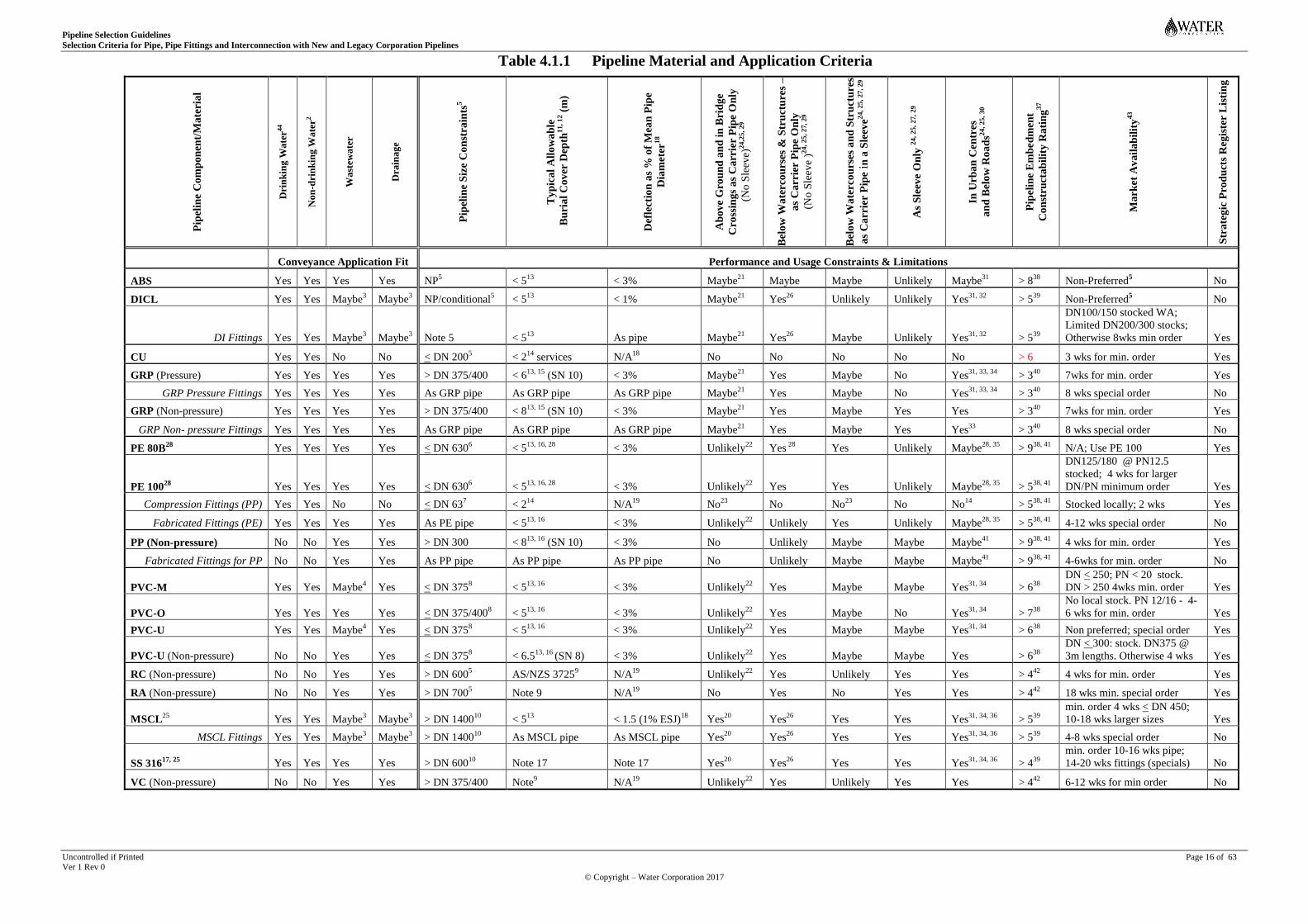
4.1.1 Material and Application Comparison
Table 4.1.1 outlines default material criteria for comparing and selecting pipe, pipe fitting and
associated jointing system materials, that are commonly available in WA, for particular pipeline
project applications. Table 4.1.1 should be read in conjunction with the supplementary guidance in
“Notes for Table 4.1.1”.
Pipeline Selection Guidelines
Selection Criteria for Pipe, Pipe Fittings and Interconnection with New and Legacy Corporation Pipelines
Uncontrolled if Printed Page 16 of 63 Ver 1 Rev 0
© Copyright – Water Corporation 2017
Table 4.1.1 Pipeline Material and Application Criteria
Pip
elin
e C
om
po
nen
t/M
ate
ria
l
Dri
nk
ing
Wa
ter4
4
No
n-d
rin
kin
g W
ate
r2
Wa
stew
ate
r
Dra
ina
ge
Pip
elin
e S
ize
Co
nst
rain
ts5
Ty
pic
al
All
ow
ab
le
Bu
ria
l C
ov
er D
epth
11,
12 (
m)
Def
lect
ion
as
% o
f M
ean
Pip
e
Dia
met
er18
Ab
ov
e G
rou
nd
an
d i
n B
rid
ge
Cro
ssin
gs
as
Ca
rrie
r P
ipe
On
ly
(No
Sle
eve)
24,2
5, 29
Bel
ow
Wa
terco
urs
es &
Str
uct
ure
s –
as
Ca
rrie
r P
ipe
On
ly
(No
Sle
eve
)24, 25
, 27,
29
Bel
ow
Wa
terco
urs
es a
nd
Str
uct
ure
s
as
Ca
rrie
r P
ipe
in a
Sle
eve
24, 25
, 27
, 29
As
Sle
eve O
nly
24,
25
, 27,
29
In U
rb
an
Cen
tres
an
d B
elo
w R
oa
ds2
4,
25,
30
Pip
elin
e E
mb
ed
men
t
Co
nst
ruct
ab
ilit
y R
ati
ng
37
Ma
rket
Av
ail
ab
ilit
y43
Str
ate
gic
Pro
du
cts
Reg
iste
r L
isti
ng
Conveyance Application Fit Performance and Usage Constraints & Limitations
ABS Yes Yes Yes Yes NP5 < 5
13 < 3% Maybe
21 Maybe Maybe Unlikely Maybe
31 > 8
38 Non-Preferred
5 No
DICL Yes Yes Maybe3 Maybe
3 NP/conditional
5 < 5
13 < 1% Maybe
21 Yes
26 Unlikely Unlikely Yes
31, 32 > 5
39 Non-Preferred
5 No
DI Fittings Yes Yes Maybe3 Maybe
3 Note 5 < 5
13 As pipe Maybe
21 Yes
26 Maybe Unlikely Yes
31, 32 > 5
39
DN100/150 stocked WA;
Limited DN200/300 stocks;
Otherwise 8wks min order Yes
CU Yes Yes No No < DN 2005 < 2
14 services N/A
18 No No No No No > 6 3 wks for min. order Yes
GRP (Pressure) Yes Yes Yes Yes > DN 375/400 < 613, 15
(SN 10) < 3% Maybe21
Yes Maybe No Yes31, 33, 34
> 340
7wks for min. order Yes
GRP Pressure Fittings Yes Yes Yes Yes As GRP pipe As GRP pipe As GRP pipe Maybe21
Yes Maybe No Yes31, 33, 34
> 340
8 wks special order No
GRP (Non-pressure) Yes Yes Yes Yes > DN 375/400 < 813, 15
(SN 10) < 3% Maybe21
Yes Maybe Yes Yes > 340
7wks for min. order Yes
GRP Non- pressure Fittings Yes Yes Yes Yes As GRP pipe As GRP pipe As GRP pipe Maybe21
Yes Maybe Yes Yes33
> 340
8 wks special order No
PE 80B28
Yes Yes Yes Yes < DN 6306 < 5
13, 16, 28 < 3% Unlikely
22 Yes
28 Yes Unlikely Maybe
28, 35 > 9
38, 41 N/A; Use PE 100 Yes
PE 10028
Yes Yes Yes Yes < DN 6306 < 5
13, 16, 28 < 3% Unlikely
22 Yes Yes Unlikely Maybe
28, 35 > 5
38, 41
DN125/180 @ PN12.5
stocked; 4 wks for larger
DN/PN minimum order Yes
Compression Fittings (PP) Yes Yes No No < DN 637 < 2
14 N/A
19 No
23 No No
23 No No
14 > 5
38, 41 Stocked locally; 2 wks Yes
Fabricated Fittings (PE) Yes Yes Yes Yes As PE pipe < 513, 16
< 3% Unlikely22
Unlikely Yes Unlikely Maybe28, 35
> 538, 41
4-12 wks special order No
PP (Non-pressure) No No Yes Yes > DN 300 < 813, 16
(SN 10) < 3% No Unlikely Maybe Maybe Maybe41
> 938, 41
4 wks for min. order Yes
Fabricated Fittings for PP No No Yes Yes As PP pipe As PP pipe As PP pipe No Unlikely Maybe Maybe Maybe41
> 938, 41
4-6wks for min. order No
PVC-M Yes Yes Maybe4 Yes < DN 375
8 < 5
13, 16 < 3% Unlikely
22 Yes Maybe Maybe Yes
31, 34 > 6
38
DN < 250; PN < 20 stock.
DN > 250 4wks min. order Yes
PVC-O Yes Yes Yes Yes < DN 375/4008 < 5
13, 16 < 3% Unlikely
22 Yes Maybe No Yes
31, 34 > 7
38
No local stock. PN 12/16 - 4-
6 wks for min. order Yes
PVC-U Yes Yes Maybe4 Yes < DN 375
8 < 5
13, 16 < 3% Unlikely
22 Yes Maybe Maybe Yes
31, 34 > 6
38 Non preferred; special order Yes
PVC-U (Non-pressure) No No Yes Yes < DN 3758 < 6.5
13, 16 (SN 8) < 3% Unlikely
22 Yes Maybe Maybe Yes > 6
38
DN < 300: stock. DN375 @
3m lengths. Otherwise 4 wks Yes
RC (Non-pressure) No No Yes Yes > DN 6005 AS/NZS 3725
9 N/A
19 Unlikely
22 Yes Unlikely Yes Yes > 4
42 4 wks for min. order Yes
RA (Non-pressure) No No Yes Yes > DN 7005 Note 9 N/A
19 No Yes No Yes Yes > 4
42 18 wks min. special order Yes
MSCL25
Yes Yes Maybe3 Maybe
3 > DN 1400
10 < 5
13 < 1.5 (1% ESJ)
18 Yes
20 Yes
26 Yes Yes Yes
31, 34, 36 > 5
39
min. order 4 wks < DN 450;
10-18 wks larger sizes Yes
MSCL Fittings Yes Yes Maybe3 Maybe
3 > DN 1400
10 As MSCL pipe As MSCL pipe Yes
20 Yes
26 Yes Yes Yes
31, 34, 36 > 5
39 4-8 wks special order No
SS 31617, 25
Yes Yes Yes Yes > DN 60010
Note 17 Note 17 Yes20
Yes26
Yes Yes Yes31, 34, 36
> 439
min. order 10-16 wks pipe;
14-20 wks fittings (specials) No
VC (Non-pressure) No No Yes Yes > DN 375/400 Note9 N/A
19 Unlikely
22 Yes Unlikely Yes Yes > 4
42 6-12 wks for min order No

Pipeline Selection Guidelines
Selection Criteria for Pipe, Pipe Fittings and Interconnection with New and Legacy Corporation Pipelines
Uncontrolled if Printed Page 17 of 63 Ver 1Rev 0
© Copyright Water Corporation 2017
Notes for Table 4.1.1
1 The following are essential considerations in a pipeline selection process intended to shortlist pipeline component options that are likely to be appropriate and feasible in terms of:
Mutual assurance by the suppliers of different pipeline components that the integrity of a planned pipeline system will not be compromised by the poor or non-compliant performance of any individual component;
Compatibility of component material, engineering and jointing characteristics with installability, operability and service longevity requirements;
Impacts of elevated temperature, frequent cyclic pressure fluctuations and creep (loss of strength/stiffness over time) on pipe material (e.g. plastics) and, hence, pipe sensitivity to poor quality/uncontrolled pipeline embedment;
Inter-connectibility of pressure and non-pressure pipeline components under consideration with adjoining new and legacy conveyance pipeline system components;
Added whole of Corporation pipeline system ownership, operational and maintenance business value, over the designated pipeline life;
Market availability of pipeline components in the project specific sizes and quantities and within the planned project materials supply lead times;
Specific provision for component operational, repair and maintenance spares aimed at minimizing service disruptions and outages in the context of Operating Licence services flow, pressure and continuity requirements;
2 Non-drinking water means any water other than drinking water - including wastewater, storm-water, bore water, ground water, lake or river water - which has been treated to meet a qualitative standard defined by the appropriate
Regulator and which complies with the requirements for its intended end use.
3 General Portland cement lined pipes and pipe fittings should not be used for non-pressure wastewater applications. Their use in pressure wastewater applications - including consideration of AS 4321 or AS/NZS 4158 compliant
MDPE or FBE lining or AS/NZS 2280 compliant calcium aluminate cement mortar lining - should be supported by an evaluation that assures lining longevity and maintainability wherever exposed to pipeline borne fluids and
gases. An assurance of (absolute) minimum steady state positive head values > 7.5 kPa within a pressure pipeline system throughout its operational life may be a significant element of assuring the required longevity performance.
4 The superior fatigue performance of PVC-O as a pressure pipe material, coupled with limited market availability of PVC-M or PVC-U pipe of an appropriately high pressure rating, is likely to render the selection of PVC-M and
PVC-U pressure pipe commercially unviable for applications that routinely involve frequent pressure cycling (e.g. wastewater pumping applications) and elevated temperatures, having due regard to Table 4.5 data.
5 General consideration of pipeline sizes other than those shown in the Table should be supported by acceptable evidence of their prior satisfactory use on agreed trial projects in accordance with a control process that evaluates and
documents the quality of all elements of pipeline system design, manufacture, supply, delivery, installation and serviceability performance. In some cases, non-preferred pipe materials and sizes (e.g. ABS and DI pipe of any size
and CU pipe for other than property service applications) should not be considered for selection for new pipeline projects, in the absence of prior technical, business and risk justification that is acceptable to and authorised by the
Corporation for general infrastructure use.
6 Refer Table A1 for background to the service constraint and operating licence risks associated with the selection of PE pipe sizes larger than DN 630 for Corporation services.
7 Compression fittings are available for PE pipe larger than DN 63 but have been associated with incomplete joint sealing where formal installer training is not a documented requirement and where the execution of installation
practices that are poorly controlled/supervised or not subjected to ongoing performance compliance auditing of substance.
8 Some product standards designate DN 375 Series 2 PVC pressure pipe as DN 400, albeit the same nominal size. Where DN 450 non-pressure (AS/NZS 1260) PVC pipe is not commonly manufactured, DN 450 PVC pressure pipe
may be considered subject, as always, to market availability (from eastern states), agreed minimum purchase quantities and appropriate management/control of long distance handling and transportation logistics and risks.
9 Design of RC, RA and VC pipeline systems including loadings, cover depth and bedding factors for alternative embedment arrangements should be in accordance with the requirements and guidance respectively set out in AS/NZS
3725:2007 “Design for installation of buried concrete pipes” and AS 4060-1992 “Loads on buried vitrified clay pipes” and associated Supplements AS/NZS 3725 Supp 1:2007 “Design for installation of buried concrete pipes –
Commentary” and AS 4060 Supp 1-1992 “Loads on buried vitrified clay pipes – Commentary”, respectively
10 Table 4.2 sets out indicative mechanical characteristics for steel pipes < DN 1400. Consideration of larger sizes is noted elsewhere in Table 4.1.1 Notes.
11 The indicative pipeline cover depth values shown are for comparison purposes. Designers should determine maximum burial cover depth values for individual applications by calculating the capacity of pipeline material,
dimensions, pressure/stiffness classes and allowable pipe hoop stress/strain values to resist, subject to appropriate design (or safety) factors:
deflection or diametral deformation in excess of the values shown within 30 days of installation and burial, notwithstanding the values shown in AS/NZS 2566.2 Table 5.6 for an assumed high quality embedment installation
and compaction. The application of additional design (safety) factors may be required to address inferior and unsupervised embedment work expectations;
buckling, having due regard to the potential for occurrence of positive or negative internal pressure extremes and external soil and hydrostatic loads, simultaneously or not;
imposed embankment (as distinct from trench) condition loads.
12 Structurally unprotected pipe burial cover depth should generally exceed 0.75 - where unpaved - or 0.6m - where paved to an acceptable paving and paving support structural specification - as an absolute minimum. Shallower
cover depths may be considered by exception where engineering and risk analyses of pipeline/embedment design clearly assure safe structural, operational and service feasibility. Deeper burial cover depths may apply where a
buried pipeline is to be exposed to:
unavoidable conflict with other buried services or service alignments;
vehicular and other imposed surface loads - including construction equipment loads - during pipeline installation work;
change of direction involving constructed thrust block supports;
horizontal or vertical proximity to other existing or proposed structural or built assets whose integrity or stability may be compromised by pipeline installation and - particularly in the case of viscoelastic (e.g. PE/PP) pressure
pipe - its expansion and contraction in service and during pipeline field pressure testing operations.
The use of concrete bulkhead/trench stop thrust restraints or cement stabilised embedment in accordance with the provisions of AS/NZS 2566.2 may be considered to provide structural stability where fill strength is poor, where
cover depths are shallow and where pipeline gradients are steep.
13 Where any pipe selection is under consideration for depths exceeding the typical cover depth values shown, designers should verify the design basis and safety margin against failure due to excessive deflection (ring bending) or
buckling where subject to trench and embankment loading conditions as applicable, by calculation and by reference to the pipe manufacturer as necessary. Higher cover depths may be considered where supported by (i) embedment
and structural design calculations using appropriate design/safety factors and (ii) by an acceptable specification for pipeline installation including appropriate (embedment/compaction) quality inspection and testing controls.

Pipeline Selection Guidelines
Selection Criteria for Pipe, Pipe Fittings and Interconnection with New and Legacy Corporation Pipelines
Uncontrolled if Printed Page 18 of 63 Ver 1Rev 0
© Copyright Water Corporation 2017
Notes for Table 4.1.1 (continued)
14 Small bore PE and copper pipelines with compression and silver brazed joints respectively are intended for use at shallow depths away from paved roads e.g. property services. The use of PE pipeline compression fittings in buried
applications should be limited to shallow off-road verge applications where the impacts of poor embedment quality are lower risk.
15 Where GRP pipe is under consideration, designers should, in particular, consider the comparatively limited ring bending strain capacity of GRP pipe.
16 The typical burial cover depths values shown for PE pressure and PP/PVC non-pressure pipe may be increased in conveyance applications where pipeline structure, stiffness, embedment and pipe deflection design calculations
together with appropriate installation performance control specifications are provided to the Corporation and are shown to safely support the higher values.
17 Consideration of SS pipeline systems for conveyance applications should be determined on a project by project basis, subject to project justification including specific material (e.g. 316L or super duplex SS) need, the corrosive
characteristics of pipeline borne fluids & gases, the extent of external exposure to corrosive environments, structural longevity performance and pipeline system life economics.
18 The typical allowable vertical pipe deflection values shown are lower than the 30 day values shown in AS/NZS 2566.2 Table 5.6 to address the risk of inferior, untested or unproven embedment work except where appropriate high
quality installation, inspection and testing performance verification practices are demonstrably assured. Where steel pipeline joints are to be elastomerically sealed, allowable deflection values are generally lower (< 1%) than (<
1.5%) where pipeline joints are welded in accordance with WS-1.
19 No vertical deflection criteria are nominated, given other application constraints on the location of Cu pipe and compression fittings for PE pipe and the need to constrain RC, RA and unreinforced VC (rigid) pipe loads and crack
development by virtue of a well-designed and tested pipeline/embedment in accordance with an assured embedment performance specification.
20 "Yes" indicates materials that should be prime candidates for above ground and bridge crossing applications, given appropriate design of pipeline structure, coating & protection systems, expansion/contraction potential and
associated thrust restraint systems.
21 "Maybe" indicates materials that may be potential candidates for above ground and bridge crossing applications, provided that the mechanical/structural feasibility and economic viability of pipeline structure, protection systems
and thrust restraint systems are supported by acceptable design basis assumptions including design factor selection that safely assures the required longevity performance.
22 "Unlikely" indicates pipeline materials that, except where justified by particular project needs and risk analyses, are unlikely to provide the required service duration and least risk performance in above ground and bridge crossing
applications. Risk considerations include thermal and creep characteristics, material/coating/lining susceptibility to heat and UV damage and in-service performance of pipe structure and jointing (thrust restrained or not) systems.
23 The use of compression jointed fittings under watercourses, significant structures or buried/concealed hard-to-access locations would present significant risk in the event of failures.
24 An engineering design basis, of an acceptable rigour, should be documented to support the:
Selection, engineering evaluation and design of carrier and sleeve encasement/containment pipelines in terms of structural viability, buckling resistance and joint integrity over designated pipeline service life;
Design and specification of embedment performance parameters for open cut/trenched applications and system control and installation methodology for trenchless applications (Refer Table 4.1.2 and Table 4.1.2 Notes).
25 The designer is accountable for evaluating the extent, if any, exposure of metallic pipeline to high voltage (> 11kV) transmission lines and cables where continuously welded and for designing the pipeline to mitigate the associated
risk of corrosion, in accordance with the guidance in DS 91 and requirements of DS 23 as appropriate.
26 Where DI or steel pipe may be under consideration as part of a carrier pipeline or sleeve (encasement) under watercourses or significant structures, its selection/design should provide for corrosion prevention measures including
tested coating and wrapping systems (in accordance with DS 95) to assure the required longevity performance and address pipeline exposure to external atmospheric and subterranean electrolytes over its designated service life.
27 The acceptability of pipe materials and pipe jointing systems for sleeve and carrier applications (i.e. for stand-alone carrier pipe, carrier pipe inside a sleeve or structural sleeve for a carrier pipe), using open cut/fill or trenchless
techniques beneath a significant watercourse, structure or obstacle, should be specifically demonstrated in terms of:
Whole of sleeve/carrier longevity, engineering, installability, in-service risks and value for money (Table 4.1.2 provides guidance on the selection of and risk rating criteria for pipeline materials in trenchless applications);
Pipeline and soil embedment structural stability, safety, security and durability during installation and during subsequent sleeve/carrier operations and maintenance over the designated service life, given the community impacts
of premature sleeve/carrier pipe failure or instability and the logistics of pipeline repair and replacement operations;
Durability, stability and security of un-grouted carrier pressure pipe within a non-corrodible permanent sleeve pipe - typically by means of non-corrodible sleeve/casing spacers, spiders or supports of an acceptable design -
where located beneath designated (existing and future) freeways, highways, railways and environmentally sensitive areas, given the impracticability - and unacceptability to asset owners - of open cut/fill installation techniques
and the unacceptable impacts of premature carrier pipe failure (e.g. traffic disruption, carrier pipe repair/replacement logistics and service outages;
The need to structurally grout sleeve/carrier pipeline annulus (A) where located beneath designated freeways, highways, railways and environmentally sensitive areas or otherwise, (B) where a selected sleeve pipe material is
corrodible (e.g. carbon steel) or may be incapable of safely bearing imposed loads or outlasting its inner carrier pipe and (C) where a selected carrier pipe material and may be structurally unstable (e.g. PE pipe).
The complexity (high cost and high failure risk) of future repair or replacement, where a carrier pipe with protruding, cast, moulded, fabricated or socketed (e.g. fusion) fittings is being considered for installation in a sleeve;
The improbability of RC as a viable carrier pipe material, where considered for installation in a sleeve pipe of RC or another material;
The improbability of flexibly (elastomeric seal) jointed pipe (e.g. DI, PVC, GRP) as a viable/acceptable carrier pipeline beneath significant watercourses, structures or obstacles, given pipeline inherent lack of structural,
hydraulic continuity or (unanchored) axial restraint capability and given the impracticability of pipeline joint installation, pressure testing and repair or replacement in place.

Pipeline Selection Guidelines
Selection Criteria for Pipe, Pipe Fittings and Interconnection with New and Legacy Corporation Pipelines
Uncontrolled if Printed Page 19 of 63 Ver 1Rev 0
© Copyright Water Corporation 2017
Notes for Table 4.1.1 (continued)
28 Consideration of PE pipe for selection should provide for market availability/supply constraints, inherent welding/handling/installation inefficiencies, thermal movement characteristics and related economic impacts, including:
Repairability constraints due to the impracticability of lengthy service shutdowns for repair (emptying, drying, fusion heating and cooling time) and availability of axially restrained mechanical coupling systems together with
accompanying (mandatory) split stainless steel stiffeners for insertion into the PE pipe spigots to be mechanically jointed;
The constructability, cost inefficiencies and safety risks that are certain to arise where PE pipe is proposed for installation in an open cut trench traversed by multiple closely spaced utility services - due to the need to fusion joint
PE pipe in many short lengths in a confined trench, as compared with its installation in long lengths (fusion jointed on the surface) where conflicting utility services are lesser in number and farther apart;
Need to select pipe SDR values, that are higher (e.g. > 10% thicker walled) than required to withstand calculated pipeline design pressures, for trenchless installation where potentially exposed to sharp or angular soil particles;
The logistical practicability (or not) of establishing - and dis-establishing - pipe transportation, joint alignment, surface preparation and fusion equipment in remote locations - particularly for large PE pipelines;
The expansive/uplift effects of visco-elastic (e.g. PE) pipe where buried below overlying road and other built structures, particularly for large pipe sizes, small cover depths and fluctuating low/high service/field test pressures.
Allowable PE pipeline pressures should be calculated by reference to this Table, Tables 4.2, 4.5, A1 and A2 and associated Table Notes. The “informative” service (design) coefficient values in AS/NZS 4130:2009 Table C1
should not be applied as a basis for re-rating allowable PE pipeline pressure values for water or wastewater conveyance applications.
29 The selection of pipeline materials and jointing systems for trenchless applications should be on the basis of least risk or specified risk mitigation measures, in accordance with the guidance in Table 4.1.2 and associated Notes.
30 Selection of new pipeline components for use in buried urban centres, heavily trafficked roads, narrow road reserves, paved urban laneways and other areas with multiple utility services should include:
Compliance with requirements in the Utility Providers Code of Practice for service locations, depths and alignment corridors;
Planned mitigation measures to minimize the disturbance impacts and risks to existing Corporation and other utility services that rely on existing undisturbed soil to bear existing unbalanced pipeline thrusts;
Planned measures to address the site logistics of lengthy pipe 'strings' & sections of open trench, bulky (transportation & fusion) equipment space requirements as well as installation feasibility and economics.
31 The use of elastomeric seal jointed pressure pipe - particularly in larger (> DN 250) sizes - may require thrust blocks that are not physically nor economically constructible within prescribed service alignments and depths. In
general, pipeline thrust restraint options – including designed thrust blocks - should be selected on the basis of structural stability, given the risk of de-stabilizing of other utility services that may adjoin them and the risk of poor/no
quality control where others undertake sub-surface work and where there are multiple services and alignment constraints. The limited use (on agreed projects only) of non-preferred Series 1 solvent weld jointed plastics pipe should
be considered only where justified on the basis of substantial (proven) life cost advantage in comparison with other pipe material and joint configuration options.
32 The use of (corrosion protected) flanged - in lieu of flexible socketed - jointing of DI pipeline components may be justifiable on the basis of life cost advantage when compared with other pipe material and joint configuration
options, provided that the impracticability of field DI welding and induced electrical voltage potential are adequately evaluated and provided for in project cost/risk analyses.
33 The use of butt & strap - in lieu of flexible socketed - jointing of GRP pipeline components may be justifiable on the basis of life cost advantage, compared with other pipe material and joint configuration options.
34 Straight flexibly socketed pipeline 'runs' may be supplemented with sections of flanged, welded (e.g. DI/MS) or 'butt & strapped' (e.g. GRP) components for a sufficient length on both 'sides' of pipeline direction changes to
obviate the need for thrust blocks, where justified on the basis of life cost advantage, compared with other pipe material and joint configuration options.
35 Justification for the use of fusion jointed PE pipeline components should include consideration of the logistical impacts and the practicability of installing lengthy pipe 'strings' in open cut trenches where road/lane reserves are
narrow and services congested, given the bulk and maneuverability requirements of fusion, re-rounding, positioning and preparation equipment as well as the need to efficiently and economically manage wet pipeline conditions,
work duration and logistics of fusion joint heating, cooling and proof testing.
36 Steel pipeline welding, welder competencies and conformity of weld and welder accreditation should be (and shown on project records to be) in accordance with WS-1 requirements.
37 Pipeline selection & design should include justification for the constructability of pipeline materials and their relative sensitivity to the poor quality pipeline embedment design, installation and compliance testing. Constructability
is ranked to reflect the relative importance of good embedment quality design/specifications, embedment installation and its quality assurance by inspection and compliance testing. Embedment sensitivity to sub-standard, non-
compliant and infrequent (or no) quality testing is ranked on a scale of 1 (insensitive) to 10 (very sensitive), to reflect the selection, design, installation and embedment compliance testing rigour required.
38 As plastics pipe materials are very sensitive to creep induced stiffness reduction, load and thermal induced deflection, ovality and scratch/notch induced damage, pipeline embedment should be designed and installed in compliance
with a (nominated) high quality pipeline embedment specification that assures an acceptable service longevity. As shown in Table 4.2, the short & long term stiffness of PVC-O pipe is much lower than for like PVC-M or PVC-U
pipe. PVC pipe should be installed only by PVC pipe-layers who have been formally accredited by a Registered Training Organization in accordance with industry training modules that are nominated by the Corporation.
39 The flexibility of DI, MS & SS pipeline shell materials, although comparatively rigid, renders them moderately sensitive to poor embedment design, installation and compliance testing practices. More critically, poor embedment
quality could potentially lead to excessive DI/MS pipe cement mortar lining strain and excessive pipe ovality which would, in turn, cause flexible joints to fail where joint (but not pipe barrel) deflection capacity is exceeded.
40 The low ring bending strain capacity of GRP pipe material renders it sensitive to deflection induced failure - particularly in embankment - as distinct from trench - conditions.
41 PP and PE pipeline components are exceptionally sensitive to poor embedment design, installation performance testing and compliance practices. They also perform poorly where exposed to on-site handling and fusion welding -
practices undertaken by other than experienced welders and welding service providers who have been duly qualified and accredited in accordance with WS-2.
42 The sensitivity of rigid (RC, RA and VC) pipelines to strain related cracking should be addressed by assuring good embedment design & installation (to AS/NZS 3725 and AS 4060 respectively) and compliance testing practices.
43 The information on pipe component availability is indicative only and can vary significantly from time to time and from one supplier to another. It is likely to be very dependent on project quantum needs and timing. Availability
for particular projects and applications should be evaluated by designers well in advance of a final selection for nomination on project drawings. Market enquiries should be particularly pro-active where potential project orders
could involve larger (> DN 250) pipe sizes, short pipeline lengths (i.e. product volumes small relative to a commercial pipe production run) and correspondingly long supply lead times.
44 All pipeline components in contact with drinking water should comply with AS/NZS4020 for an acceptable minimum component surface to water volume ratio (or scaling factor).
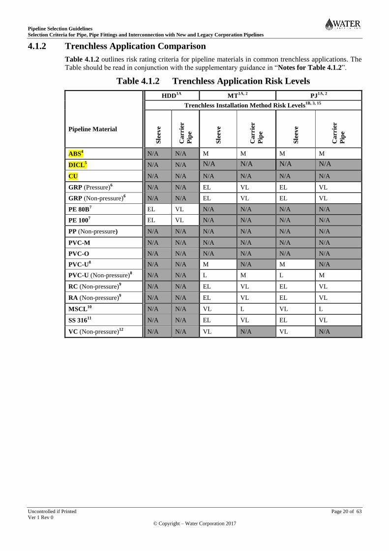
Pipeline Selection Guidelines
Selection Criteria for Pipe, Pipe Fittings and Interconnection with New and Legacy Corporation Pipelines
Uncontrolled if Printed Page 20 of 63 Ver 1 Rev 0
© Copyright – Water Corporation 2017
4.1.2 Trenchless Application Comparison
Table 4.1.2 outlines risk rating criteria for pipeline materials in common trenchless applications. The
Table should be read in conjunction with the supplementary guidance in “Notes for Table 4.1.2”.
Table 4.1.2 Trenchless Application Risk Levels
HDD1A
MT1A, 2
PJ1A, 2
Trenchless Installation Method Risk Levels1B, 3, 15
Pipeline Material
Sle
eve
Ca
rrie
r
Pip
e
Sle
eve
Ca
rrie
r
Pip
e
Sle
eve
Ca
rrie
r
Pip
e
ABS4 N/A N/A M M M M
DICL5 N/A N/A N/A N/A N/A N/A
CU N/A N/A N/A N/A N/A N/A
GRP (Pressure)6 N/A N/A EL VL EL VL
GRP (Non-pressure)6 N/A N/A EL VL EL VL
PE 80B7 EL VL N/A N/A N/A N/A
PE 1007 EL VL N/A N/A N/A N/A
PP (Non-pressure) N/A N/A N/A N/A N/A N/A
PVC-M N/A N/A N/A N/A N/A N/A
PVC-O N/A N/A N/A N/A N/A N/A
PVC-U8 N/A N/A M N/A M N/A
PVC-U (Non-pressure)8 N/A N/A L M L M
RC (Non-pressure)9 N/A N/A EL VL EL VL
RA (Non-pressure)9 N/A N/A EL VL EL VL
MSCL10
N/A N/A VL L VL L
SS 31611
N/A N/A EL VL EL VL
VC (Non-pressure)12
N/A N/A VL N/A VL N/A
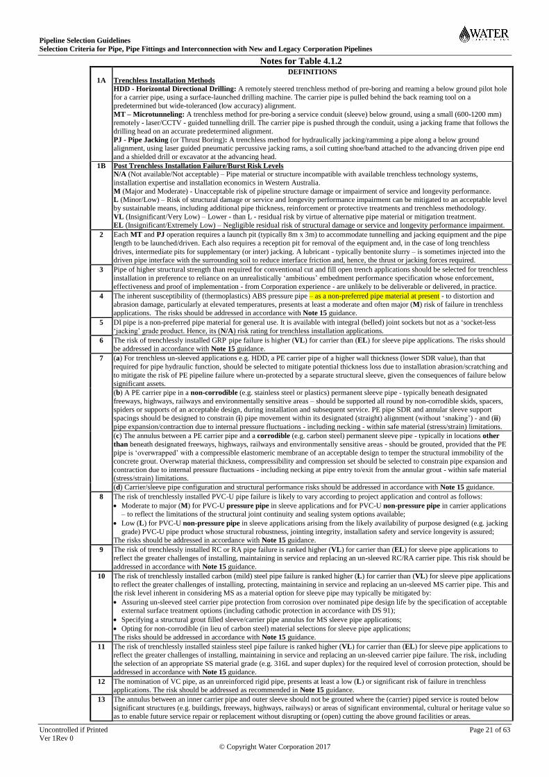
Pipeline Selection Guidelines
Selection Criteria for Pipe, Pipe Fittings and Interconnection with New and Legacy Corporation Pipelines
Uncontrolled if Printed Page 21 of 63
Ver 1Rev 0
© Copyright Water Corporation 2017
Notes for Table 4.1.2
1A
DEFINITIONS
Trenchless Installation Methods
HDD - Horizontal Directional Drilling: A remotely steered trenchless method of pre-boring and reaming a below ground pilot hole for a carrier pipe, using a surface-launched drilling machine. The carrier pipe is pulled behind the back reaming tool on a
predetermined but wide-toleranced (low accuracy) alignment.
MT – Microtunneling: A trenchless method for pre-boring a service conduit (sleeve) below ground, using a small (600-1200 mm) remotely - laser/CCTV - guided tunnelling drill. The carrier pipe is pushed through the conduit, using a jacking frame that follows the
drilling head on an accurate predetermined alignment.
PJ - Pipe Jacking (or Thrust Boring): A trenchless method for hydraulically jacking/ramming a pipe along a below ground alignment, using laser guided pneumatic percussive jacking rams, a soil cutting shoe/band attached to the advancing driven pipe end
and a shielded drill or excavator at the advancing head.
1B Post Trenchless Installation Failure/Burst Risk Levels
N/A (Not available/Not acceptable) – Pipe material or structure incompatible with available trenchless technology systems,
installation expertise and installation economics in Western Australia.
M (Major and Moderate) - Unacceptable risk of pipeline structure damage or impairment of service and longevity performance. L (Minor/Low) – Risk of structural damage or service and longevity performance impairment can be mitigated to an acceptable level
by sustainable means, including additional pipe thickness, reinforcement or protective treatments and trenchless methodology.
VL (Insignificant/Very Low) – Lower - than L - residual risk by virtue of alternative pipe material or mitigation treatment. EL (Insignificant/Extremely Low) – Negligible residual risk of structural damage or service and longevity performance impairment.
2 Each MT and PJ operation requires a launch pit (typically 8m x 3m) to accommodate tunnelling and jacking equipment and the pipe
length to be launched/driven. Each also requires a reception pit for removal of the equipment and, in the case of long trenchless
drives, intermediate pits for supplementary (or inter) jacking. A lubricant - typically bentonite slurry – is sometimes injected into the driven pipe interface with the surrounding soil to reduce interface friction and, hence, the thrust or jacking forces required.
3 Pipe of higher structural strength than required for conventional cut and fill open trench applications should be selected for trenchless
installation in preference to reliance on an unrealistically ‘ambitious’ embedment performance specification whose enforcement,
effectiveness and proof of implementation - from Corporation experience - are unlikely to be deliverable or delivered, in practice.
4 The inherent susceptibility of (thermoplastics) ABS pressure pipe – as a non-preferred pipe material at present - to distortion and abrasion damage, particularly at elevated temperatures, presents at least a moderate and often major (M) risk of failure in trenchless
applications. The risks should be addressed in accordance with Note 15 guidance.
5 DI pipe is a non-preferred pipe material for general use. It is available with integral (belled) joint sockets but not as a ‘socket-less
‘jacking’ grade product. Hence, its (N/A) risk rating for trenchless installation applications.
6 The risk of trenchlessly installed GRP pipe failure is higher (VL) for carrier than (EL) for sleeve pipe applications. The risks should be addressed in accordance with Note 15 guidance.
7 (a) For trenchless un-sleeved applications e.g. HDD, a PE carrier pipe of a higher wall thickness (lower SDR value), than that
required for pipe hydraulic function, should be selected to mitigate potential thickness loss due to installation abrasion/scratching and
to mitigate the risk of PE pipeline failure where un-protected by a separate structural sleeve, given the consequences of failure below significant assets.
(b) A PE carrier pipe in a non-corrodible (e.g. stainless steel or plastics) permanent sleeve pipe - typically beneath designated
freeways, highways, railways and environmentally sensitive areas – should be supported all round by non-corrodible skids, spacers,
spiders or supports of an acceptable design, during installation and subsequent service. PE pipe SDR and annular sleeve support
spacings should be designed to constrain (i) pipe movement within its designated (straight) alignment (without ‘snaking’) - and (ii)
pipe expansion/contraction due to internal pressure fluctuations - including necking - within safe material (stress/strain) limitations.
(c) The annulus between a PE carrier pipe and a corrodible (e.g. carbon steel) permanent sleeve pipe - typically in locations other
than beneath designated freeways, highways, railways and environmentally sensitive areas - should be grouted, provided that the PE
pipe is ‘overwrapped’ with a compressible elastomeric membrane of an acceptable design to temper the structural immobility of the concrete grout. Overwrap material thickness, compressibility and compression set should be selected to constrain pipe expansion and
contraction due to internal pressure fluctuations - including necking at pipe entry to/exit from the annular grout - within safe material
(stress/strain) limitations.
(d) Carrier/sleeve pipe configuration and structural performance risks should be addressed in accordance with Note 15 guidance.
8 The risk of trenchlessly installed PVC-U pipe failure is likely to vary according to project application and control as follows:
Moderate to major (M) for PVC-U pressure pipe in sleeve applications and for PVC-U non-pressure pipe in carrier applications – to reflect the limitations of the structural joint continuity and sealing system options available;
Low (L) for PVC-U non-pressure pipe in sleeve applications arising from the likely availability of purpose designed (e.g. jacking
grade) PVC-U pipe product whose structural robustness, jointing integrity, installation safety and service longevity is assured; The risks should be addressed in accordance with Note 15 guidance.
9 The risk of trenchlessly installed RC or RA pipe failure is ranked higher (VL) for carrier than (EL) for sleeve pipe applications to
reflect the greater challenges of installing, maintaining in service and replacing an un-sleeved RC/RA carrier pipe. This risk should be
addressed in accordance with Note 15 guidance.
10 The risk of trenchlessly installed carbon (mild) steel pipe failure is ranked higher (L) for carrier than (VL) for sleeve pipe applications to reflect the greater challenges of installing, protecting, maintaining in service and replacing an un-sleeved MS carrier pipe. This and
the risk level inherent in considering MS as a material option for sleeve pipe may typically be mitigated by:
Assuring un-sleeved steel carrier pipe protection from corrosion over nominated pipe design life by the specification of acceptable external surface treatment options (including cathodic protection in accordance with DS 91);
Specifying a structural grout filled sleeve/carrier pipe annulus for MS sleeve pipe applications;
Opting for non-corrodible (in lieu of carbon steel) material selections for sleeve pipe applications;
The risks should be addressed in accordance with Note 15 guidance.
11 The risk of trenchlessly installed stainless steel pipe failure is ranked higher (VL) for carrier than (EL) for sleeve pipe applications to reflect the greater challenges of installing, maintaining in service and replacing an un-sleeved carrier pipe failure. The risk, including
the selection of an appropriate SS material grade (e.g. 316L and super duplex) for the required level of corrosion protection, should be
addressed in accordance with Note 15 guidance.
12 The nomination of VC pipe, as an unreinforced rigid pipe, presents at least a low (L) or significant risk of failure in trenchless applications. The risk should be addressed as recommended in Note 15 guidance.
13 The annulus between an inner carrier pipe and outer sleeve should not be grouted where the (carrier) piped service is routed below
significant structures (e.g. buildings, freeways, highways, railways) or areas of significant environmental, cultural or heritage value so as to enable future service repair or replacement without disrupting or (open) cutting the above ground facilities or areas.

Pipeline Selection Guidelines
Selection Criteria for Pipe, Pipe Fittings and Interconnection with New and Legacy Corporation Pipelines
Uncontrolled if Printed Page 22 of 63
Ver 1Rev 0
© Copyright Water Corporation 2017
14 The Strategic Products Register lists authorised products in some jacking grade pipe materials and designs on the basis of acceptable
design and installation methodology proposals. New proposals to nominate other pipe systems for trenchless applications should be
duly supported by an acceptable design basis for materials, engineering, installation and service durability performance
15 Trenchless application risk should be mitigated by prior submission of a justified feasibility, supply, installation and control methodology proposal that proves acceptable to the Corporation as prospective asset owner. The proposal should clearly identify all
pipeline components proposed for selection and should establish the design, installation and service performance risks, including:
The scope of trenchless (as compared with open cut) installation components in terms of net added benefits and asset life value, mindful of the logistics and economics of trenchlessly installed pipeline repair or replacement in the future;
Pipe material and structural grade selection, duly justified by an original pipe manufacturer, by a third party structural designer, or both where an original pipe is modified to produce a final jacking pipe product;
Successful field installation trials for pipe of the nominated 'jacking grade', strength class and service performance, demonstrated eligibility for its authorisation on the Strategic Products Register together with its market availability and supply lead times;
Pipe coating and lining structural performance during application of jacking, driving and abrasion forces – particularly where lining (e.g. cement mortar) may become unevenly or eccentrically loaded beyond its safe limits - and pipeline longevity performance,
subject to its level of exposure to corrosive installed environments over pipeline service life.
Structural integrity and continuity of pipe jointing system, fitness of trenchless drive attachments and directional precision of drive alignment control equipment and technology;
Pipe selection and trenchless installation feasibility and economics, duly informed in consultation with the owners of significant structures (e.g. buildings, freeways, highways, railways) or areas below which trenchless pipeline installation is proposed, with
regulatory authorities and with experienced trenchless constructors/installers, as appropriate;
Summary of line, level, structural and longevity performance parameters for a trenchlessly installed pipeline, clearly defined and
supported by a documented engineering basis of an appropriate rigour.
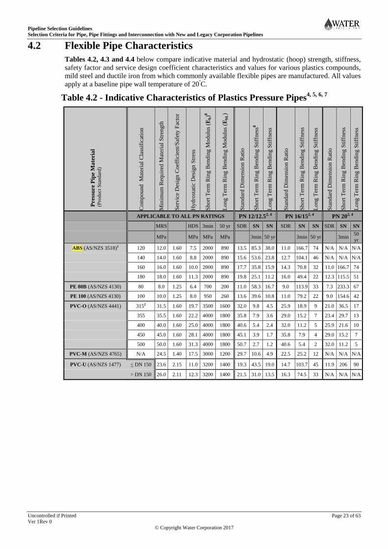
Pipeline Selection Guidelines
Selection Criteria for Pipe, Pipe Fittings and Interconnection with New and Legacy Corporation Pipelines
Uncontrolled if Printed Page 23 of 63
Ver 1Rev 0
© Copyright Water Corporation 2017
4.2 Flexible Pipe Characteristics
Tables 4.2, 4.3 and 4.4 below compare indicative material and hydrostatic (hoop) strength, stiffness,
safety factor and service design coefficient characteristics and values for various plastics compounds,
mild steel and ductile iron from which commonly available flexible pipes are manufactured. All values
apply at a baseline pipe wall temperature of 20ºC.
Table 4.2 - Indicative Characteristics of Plastics Pressure Pipes4, 5, 6, 7
P
ress
ure
Pip
e M
ate
ria
l (P
rodu
ct S
tand
ard
)
Co
mp
ou
nd
M
ater
ial
Cla
ssif
icat
ion
Min
imu
m R
equ
ired
Mat
eria
l S
tren
gth
Ser
vic
e D
esig
n C
oef
fici
ent/
Saf
ety
Fac
tor
Hy
dro
stat
ic D
esig
n S
tres
s
Sh
ort
Ter
m R
ing
Ben
din
g M
odu
lus
(Eb)8
Lo
ng
Ter
m R
ing
Ben
din
g M
od
ulu
s (E
bL)
Sta
nd
ard D
imen
sio
n R
atio
Sh
ort
Ter
m R
ing
Ben
din
g S
tiff
nes
s8
Lo
ng
Ter
m R
ing
Ben
din
g S
tiff
nes
s
Sta
nd
ard D
imen
sio
n R
atio
Sh
ort
Ter
m R
ing
Ben
din
g S
tiff
nes
s
Lo
ng
Ter
m R
ing
Ben
din
g S
tiff
nes
s
Sta
nd
ard D
imen
sio
n R
atio
Sh
ort
Ter
m R
ing
Ben
din
g S
tiff
nes
s
Lo
ng
Ter
m R
ing
Ben
din
g S
tiff
nes
s
APPLICABLE TO ALL PN RATINGS PN 12/12.52, 4 PN 16/152, 4
PN 202, 4
MRS HDS 3min 50 yr SDR SN SN SDR SN SN SDR SN SN
MPa MPa MPa MPa 3min 50 yr 3min 50 yr 3min 50
yr
ABS (AS/NZS 3518)1 120 12.0 1.60 7.5 2000 890 13.5 85.3 38.0 11.0 166.7 74 N/A N/A N/A
140 14.0 1.60 8.8 2000 890 15.6 53.6 23.8 12.7 104.1 46 N/A N/A N/A
160 16.0 1.60 10.0 2000 890 17.7 35.8 15.9 14.3 70.8 32 11.0 166.7 74
180 18.0 1.60 11.3 2000 890 19.8 25.1 11.2 16.0 49.4 22 12.3 115.5 51
PE 80B (AS/NZS 4130) 80 8.0 1.25 6.4 700 200 11.0 58.3 16.7 9.0 113.9 33 7.3 233.3 67
PE 100 (AS/NZS 4130) 100 10.0 1.25 8.0 950 260 13.6 39.6 10.8 11.0 79.2 22 9.0 154.6 42
PVC-O (AS/NZS 4441) 3152 31.5 1.60 19.7 3500 1600 32.0 9.8 4.5 25.9 18.9 9 21.0 36.5 17
355 35.5 1.60 22.2 4000 1800 35.8 7.9 3.6 29.0 15.2 7 23.4 29.7 13
400 40.0 1.60 25.0 4000 1800 40.6 5.4 2.4 32.0 11.2 5 25.9 21.6 10
450 45.0 1.60 28.1 4000 1800 45.1 3.9 1.7 35.8 7.9 4 29.0 15.2 7
500 50.0 1.60 31.3 4000 1800 50.7 2.7 1.2 40.6 5.4 2 32.0 11.2 5
PVC-M (AS/NZS 4765) N/A 24.5 1.40 17.5 3000 1200 29.7 10.6 4.9 22.5 25.2 12 N/A N/A N/A
PVC-U (AS/NZS 1477) < DN 150 23.6 2.15 11.0 3200 1400 19.3 43.5 19.0 14.7 103.7 45 11.9 206 90
> DN 150 26.0 2.11 12.3 3200 1400 21.5 31.0 13.5 16.3 74.5 33 N/A N/A N/A
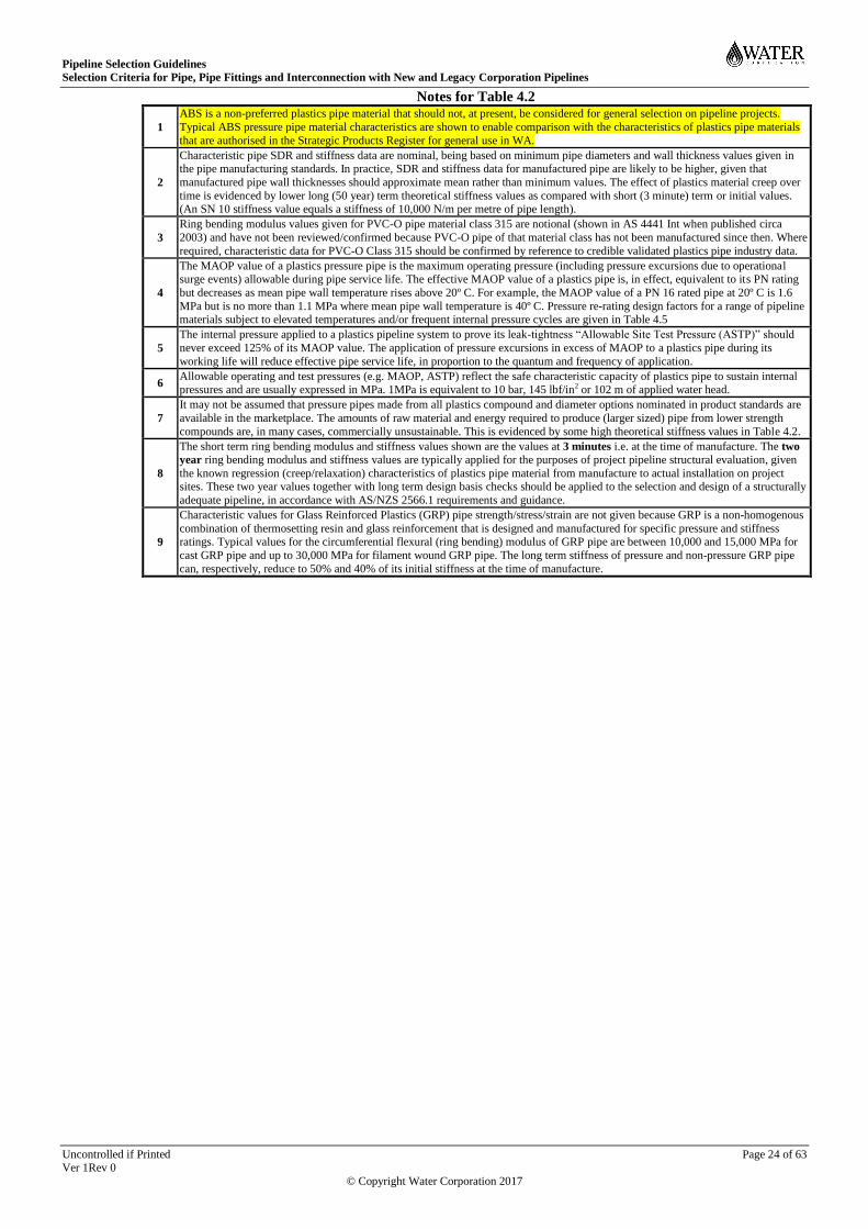
Pipeline Selection Guidelines
Selection Criteria for Pipe, Pipe Fittings and Interconnection with New and Legacy Corporation Pipelines
Uncontrolled if Printed Page 24 of 63
Ver 1Rev 0
© Copyright Water Corporation 2017
Notes for Table 4.2
1
ABS is a non-preferred plastics pipe material that should not, at present, be considered for general selection on pipeline projects.
Typical ABS pressure pipe material characteristics are shown to enable comparison with the characteristics of plastics pipe materials
that are authorised in the Strategic Products Register for general use in WA.
2
Characteristic pipe SDR and stiffness data are nominal, being based on minimum pipe diameters and wall thickness values given in the pipe manufacturing standards. In practice, SDR and stiffness data for manufactured pipe are likely to be higher, given that
manufactured pipe wall thicknesses should approximate mean rather than minimum values. The effect of plastics material creep over
time is evidenced by lower long (50 year) term theoretical stiffness values as compared with short (3 minute) term or initial values. (An SN 10 stiffness value equals a stiffness of 10,000 N/m per metre of pipe length).
3
Ring bending modulus values given for PVC-O pipe material class 315 are notional (shown in AS 4441 Int when published circa
2003) and have not been reviewed/confirmed because PVC-O pipe of that material class has not been manufactured since then. Where
required, characteristic data for PVC-O Class 315 should be confirmed by reference to credible validated plastics pipe industry data.
4
The MAOP value of a plastics pressure pipe is the maximum operating pressure (including pressure excursions due to operational surge events) allowable during pipe service life. The effective MAOP value of a plastics pipe is, in effect, equivalent to its PN rating
but decreases as mean pipe wall temperature rises above 20º C. For example, the MAOP value of a PN 16 rated pipe at 20º C is 1.6
MPa but is no more than 1.1 MPa where mean pipe wall temperature is 40º C. Pressure re-rating design factors for a range of pipeline materials subject to elevated temperatures and/or frequent internal pressure cycles are given in Table 4.5
5
The internal pressure applied to a plastics pipeline system to prove its leak-tightness “Allowable Site Test Pressure (ASTP)” should
never exceed 125% of its MAOP value. The application of pressure excursions in excess of MAOP to a plastics pipe during its
working life will reduce effective pipe service life, in proportion to the quantum and frequency of application.
6 Allowable operating and test pressures (e.g. MAOP, ASTP) reflect the safe characteristic capacity of plastics pipe to sustain internal
pressures and are usually expressed in MPa. 1MPa is equivalent to 10 bar, 145 lbf/in2 or 102 m of applied water head.
7
It may not be assumed that pressure pipes made from all plastics compound and diameter options nominated in product standards are
available in the marketplace. The amounts of raw material and energy required to produce (larger sized) pipe from lower strength
compounds are, in many cases, commercially unsustainable. This is evidenced by some high theoretical stiffness values in Table 4.2.
8
The short term ring bending modulus and stiffness values shown are the values at 3 minutes i.e. at the time of manufacture. The two
year ring bending modulus and stiffness values are typically applied for the purposes of project pipeline structural evaluation, given
the known regression (creep/relaxation) characteristics of plastics pipe material from manufacture to actual installation on project sites. These two year values together with long term design basis checks should be applied to the selection and design of a structurally
adequate pipeline, in accordance with AS/NZS 2566.1 requirements and guidance.
9
Characteristic values for Glass Reinforced Plastics (GRP) pipe strength/stress/strain are not given because GRP is a non-homogenous
combination of thermosetting resin and glass reinforcement that is designed and manufactured for specific pressure and stiffness ratings. Typical values for the circumferential flexural (ring bending) modulus of GRP pipe are between 10,000 and 15,000 MPa for
cast GRP pipe and up to 30,000 MPa for filament wound GRP pipe. The long term stiffness of pressure and non-pressure GRP pipe
can, respectively, reduce to 50% and 40% of its initial stiffness at the time of manufacture.

Pipeline Selection Guidelines
Selection Criteria for Pipe, Pipe Fittings and Interconnection with New and Legacy Corporation Pipelines
Uncontrolled if Printed Page 25 of 63
Ver 1Rev 0
© Copyright Water Corporation 2017
Table 4.3 – Indicative Characteristics of MSCL Pipe
Pip
e N
om
inal
Dia
met
er
Pip
e O
uts
ide
Dia
met
er
Ste
el P
ipe
Sh
ell
Th
ickn
ess
Cem
ent
Mo
rtar
Lin
ing
Th
ickn
ess
Lin
ed P
ipe
Insi
de
Dia
met
er
Ste
el M
inim
um
Yie
ld S
tren
gth
(M
YS
)
Rin
g S
tren
gth
at
90
% M
YS
All
ow
able
Sit
e T
est
Pre
ssu
re (
AS
TP
)
Ser
vic
e D
esig
n C
oef
fici
ent
Max
imu
m A
llo
wab
le O
per
atin
g
Pre
ssu
re (
MA
OP
) at
72%
MY
S
Lin
ed P
ipe
Rin
g B
end
ing S
tiff
nes
s
DN mm mm mm mm MPa MPa6
MPa6 SN3
(Max) ASTP2, 5 MAOP2, 5
MYS @ 90% MYS @ 72% MYS
100 114 4.8 9 86.4 300 8.51 1.25 6.8
1 2470
150 168 5 9 140 300 8.51 1.25 6.8
1 823
200 219 5 9 191 300 8.51 1.25 6.8
1 364
250 273 5 9 245 300 8.51 1.25 6.8
1 185
300 324 5 12 290 300 8.3 1.25 6.7 128
400 406 5 12 372 300 6.7 1.25 5.3 64
500 508 5 12 474 300 5.3 1.25 4.3 32
600 610 6 12 574 300 5.3 1.25 4.2 29
700 711 6 12 675 300 4.6 1.25 3.6 19
800 813 7 16 767 300 4.6 1.25 3.7 21
900 914 7 16 868 300 4.1 1.25 3.3 15
1000 1016 8 16 968 300 4.3 1.25 3.4 15
1200 1220 9 16 1170 250 3.3 1.25 2.7 12
1400 1422 11 19 1362 300 4.2 1.25 3.3 13
1400 1422 11 19 1362 2507 3.5 1.25 2.8
7 13
Notes for Table 4.3
1
The strength, pressure and stiffness values given for DN 100 to 250 steel pipe are nominal, being much lower than the actual values
derived from pipe dimensions, in order to facilitate sustainable compliance pressure testing of finished steel pipe product, using test equipment, processes and parameters that are logistically achievable and economically viable.
2
The nominated MAOP and ASTP values apply to steel pipelines with manufacturer supplied elastomeric seal sockets and some steel
that have fully WS-1 compliant welded joints (e.g. WJ-PE). The MAOP capacity of a weld-restrained elastomeric seal joint (RRJ-
WR) is considerably lower e.g. < 2.1 MPa (< DN 600) and < 1.6 MPa (DN 700 -1000). Joint configurations are defined in DS 60.
3 Steel pipe stiffness values are as nominated by the pipe manufacturer and reflect composite cement lining/steel pipe stiffnesses. Bare (unlined) steel pipe shell stiffness generally tends to be between 52% and 63% of lined pipe stiffness pipe across the size range.
4 The MAOP value of steel pipe is the maximum operating pressure (including pressure excursions due to operational surge events)
allowable during pipe service life. The PN rating of a pipe is, in effect, its MAOP value X 10 (e.g. MAOP of 2.8 MPa = PN 28
5 The pressure applied to prove steel pipeline system leak-tightness “Allowable Site Test Pressure” should not exceed the nominated
pipe ASTP value, to avoid induction of any steel pipe wall stress higher than 90% of its MYS value.
6
Allowable operating and test pressures (e.g. MAOP, ASTP) reflect the safe capacity of steel pipe to sustain internal pressures and are usually expressed in MPa. 1MPa is equivalent to 10 bar, 145 lbf/in2 or 102 m of applied water head and 2.8 MPa is equivalent to 28
bar, 406 lbf/in2 or 285.6 m of applied water head.
7
Steel pipe material of a higher yield strength (MAOP of 3.3 MPa) has, in the past, been selected for use on particular projects and
may be considered for future steel pipeline projects, subject to demonstrated value for money and proven material strength test certification.
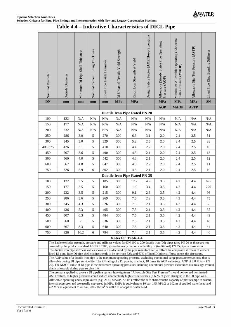
Pipeline Selection Guidelines
Selection Criteria for Pipe, Pipe Fittings and Interconnection with New and Legacy Corporation Pipelines
Uncontrolled if Printed Page 26 of 63
Ver 1Rev 0
© Copyright Water Corporation 2017
Table 4.4 – Indicative Characteristics of DICL Pipe
No
min
al D
iam
eter
Ou
tsid
e D
iam
eter
Min
imu
m D
I P
ipe
Sh
ell
Th
ickn
ess
No
min
al C
emen
t L
inin
g T
hic
kn
ess
Lin
ed P
ipe
Insi
de
Dia
met
er
DI
Un
iax
ial
Ten
sile
Yie
ld S
tren
gth
Rin
g/H
oop
Str
eng
th a
t Y
ield
Des
ign
Saf
ety
Fac
tor
(AO
P/H
oop
Str
eng
th)
All
ow
able
(S
tead
y S
tate
) P
ipe
Oper
atin
g
Pre
ssu
re (
AO
P)
Max
imu
m A
llo
wab
le O
per
atin
g (
Ab
no
rmal
Sta
te)
Pre
ssu
re (
MA
OP
)
All
ow
able
Sit
e T
est
Pre
ssu
re (
AS
TP
)
Lin
ed P
ipe
Rin
g B
end
ing S
tiff
nes
s
DN mm mm mm mm MPa MPa MPa MPa MPa SN
AOP MAOP ASTP
Ductile Iron Pipe Rated PN 20
100 122 N/A N/A N/A N/A N/A N/A N/A N/A N/A N/A
150 177 N/A N/A N/A N/A N/A N/A N/A N/A N/A N/A
200 232 N/A N/A N/A N/A N/A N/A N/A N/A N/A N/A
250 286 3.0 5 270 300 6.3 3.1 2.0 2.4 2.5 51
300 345 3.0 5 329 300 5.2 2.6 2.0 2.4 2.5 28
400/375 426 3.1 5 410 300 4.4 2.2 2.0 2.4 2.5 16
450 507 3.6 5 490 300 4.3 2.1 2.0 2.4 2.5 13
500 560 4.0 5 542 300 4.3 2.1 2.0 2.4 2.5 12
600 667 4.8 5 647 300 4.3 2.2 2.0 2.4 2.5 11
750 826 5.9 6 802 300 4.3 2.1 2.0 2.4 2.5 10
Ductile Iron Pipe Rated PN 35
100 122 3.5 5 105 300 17.2 4.9 3.5 4.2 4.4 695
150 177 3.5 5 160 300 11.9 3.4 3.5 4.2 4.4 220
200 232 3.5 5 215 300 9.1 2.6 3.5 4.2 4.4 96
250 286 3.6 5 269 300 7.6 2.2 3.5 4.2 4.4 75
300 345 4.3 5 326 300 7.5 2.1 3.5 4.2 4.4 63
400 426 5.3 5 405 300 7.5 2.1 3.5 4.2 4.4 55
450 507 6.3 5 484 300 7.5 2.1 3.5 4.2 4.4 49
500 560 7 5 536 300 7.5 2.1 3.5 4.2 4.4 48
600 667 8.3 5 640 300 7.5 2.1 3.5 4.2 4.4 44
750 826 10.2 6 794 300 7.4 2.1 3.5 4.2 4.4 40
Notes for Table 4.4
The Table excludes strength, pressure and stiffness values for DN 100 to 200 ductile iron (DI) pipes rated PN 20 as these are not
covered by the product standard AS/NZS 2280, given the ready market availability of (traditional) PN 35 pipe in those sizes.
The ductile iron pipe stiffness values shown are as declared by the pipe manufacturer to reflect the composite stiffness of cement lined DI pipe. Bare DI pipe shell stiffness tends to be between 32% and 67% of lined DI pipe stiffness across the size range.
The AOP value of a ductile iron pipe is the maximum operating pressure, excluding operational surge pressure excursions, that is
allowable during DI pipe service life. The PN rating of a DI pipe is, in effect, 10 times its AOP value (e.g. AOP of 2.0 MPa = PN
20). The MAOP value of DI pipe is the maximum operating pressure (including operational pressure excursions due to surge events) that is allowable during pipe service life.
The pressure applied to prove a DI pipeline system leak-tightness “Allowable Site Test Pressure” should not exceed nominated
ASTP values, as higher pressures could induce unacceptably high tensile stresses (> 60% of yield strength) in the DI pipe wall.
Allowable operating and test pressures (e.g. AOP, MAOP, ASTP ) reflect the safe characteristic capacity of plastics pipe to sustain
internal pressures and are usually expressed in MPa. 1MPa is equivalent to 10 bar, 145 lbf/in2 or 102 m of applied water head and 4.2 MPa is equivalent to 42 bar, 609.2 lbf/in2 or 428.3 m of applied water head.

Pipeline Selection Guidelines
Selection Criteria for Pipe, Pipe Fittings and Interconnection with New and Legacy Corporation Pipelines
Uncontrolled if Printed Page 27 of 63
Ver 1Rev 0
© Copyright Water Corporation 2017
4.3 Asset Performance Requirements
Pipeline designers, having identified potential pipeline options by reference to Tables 4.1.1 and 4.1.2
default criteria, should match pipeline asset configuration and system characteristics, selected for each
specific project, to optimal whole of asset and service performance life value. The value for money
and functional performance of the selected asset (i.e. mutually integrated pipeline components)
over its service life should be validated by the pipeline designer. The basis for asset performance
acceptance should be supported by documented value for money and engineering design
analyses of an acceptable rigour. A mutually consistent whole of asset performance warranty -
across all pipeline component manufacturers – should be pre-requisite, including:
4.3.1 Material and Engineering Properties
Typical characteristics outlined in Table 4.1.1 and associated Notes, including:
Fitness for application e.g. drinking water, non-drinking water, wastewater or drainage;
Size availability and supply lead time constraints for the pipeline sizes and quantities involved;
Maximum burial cover depth within safe buckling and nominated deflection limits;
Suitability for above ground or bridge crossing applications where relevant;
Suitability for below watercourse or structure applications where relevant;
Suitability for urban centres (e.g. congested services) and heavy road traffic load applications;
Pipeline embedment constructability rating in terms of the quality of material and compaction
specifications and of embedment work compliance, inspection and test records;
Project risk level where (selected) pipeline components have not been subjected to product
appraisal and field testing (e.g. where not registered in the Strategic Products Register).
Failure risk mitigation where pipelines are proposed for trenchless installation, mindful of the
guidance in Table 4.1.2 and associated Notes, namely:
Justification of trenchless (vs open cut) installation on basis of net value added over pipeline life;
Selection for trenchless installation of pipe class, coating, lining and jointing systems that have
been ‘proven’ - by engineering evaluation and calculation - for the structural and environmental
longevity performance required for the trenchless applications and locations;
Market availability of and supply lead times for (duly authorised) pipe of the required class/grade;
Compliance of trenchless drive alignment and control systems with required directional precision;
Justification of trenchless installation feasibility, economics and risk mitigation, duly documented
in a formal installation/methodology proposal;
Typical characteristics outlined in Table A1 and associated Notes, including:
Compliance of components with nominated reference specifications and suitability for application;
Diameter series compatibility with existing pipelines and selected size range availability;
Adequacy of rated pressures and stiffnesses for the proposed MAOP, embedment specification and
quality of embedment work inspection and testing records;
Constraints on use of standard pipe lengths or long (e.g. welded) pipe ‘strings’ where installation
space is limited and services are congested;
Adequacy of pipeline jointing specification (unrestrained/restrained) for required system integrity;
Adequacy of pipeline protection from UV and thermal radiation embrittlement
4.3.2 Location and Environment
Typical characteristics outlined in Table A2 and associated Notes, including:
Adequacy of pipeline abrasion resistance for project applications and service longevity;
Durability and long term corrosion resistance of pipeline materials, coatings & linings to corrosion,
contaminants, chemicals and high/low pH fluids;
Adequacy of metallic pipe insulation/isolation from unsafe levels of induced electrical voltage;
Pipeline material and joint seal resistance to permeation by contaminants (e.g. hydrocarbons and
solvents) by selecting non-permeable pipeline materials and more chemically resistant seal
materials (e.g. NBR or SBR in lieu of EPDM) for contaminated, gaseous (e.g. wastewater
conveyance) and undesirable taste/tainting environments, for example;
Pipeline Selection Guidelines
Selection Criteria for Pipe, Pipe Fittings and Interconnection with New and Legacy Corporation Pipelines
Uncontrolled if Printed Page 28 of 63
Ver 1Rev 0
© Copyright Water Corporation 2017
Adequacy of pipeline installation and embedment design provisions and specifications for
expansion/contraction arising from exposure to temperature variations;
Verification of pipeline joint seal adequacy for exposure to ‘full’ vacuum applications;
Adequacy of field/site acceptance test specifications for pipeline material selections;
Pipeline hydraulic profile for given site topography and subsurface geotechnical characteristics;
Environmental and heritage constraints in the vicinity of pipeline location;
Alignment with Utility Providers Code of Practice for WA constraints and requirements;
Adequacy of easement/reserve width for future pipeline access and replacement (5m to > 20m);
Prevention of pipeline flotation due to its depth and potential/seasonal ground water levels;
Practicability and cost of delivering pipeline embedment performance of the required quality where
sub-surface conditions and instability risks are high and where services are congested;
Adequacy of design provisions to protect built infrastructure above a proposed visco-elastic (e.g.
PE) pipeline, given the extent of linear & radial pipeline movement during installation and testing.
4.3.3 System Pressure Constraints and Re-rating
Characteristic pressure attributes as outlined in Tables 4.2, 4.3 & 4.4:
The different approaches in pipe product standards to defining pipeline system pressure capabilities
- MAOP (maximum allowable dynamic – i.e. including operating surge - pressure) and ASTP
(allowable site test pressure required - to prove system leak-tightness and general integrity), being:
MAOP
PN rating divided by 10 (MPa) for plastics pipelines at a baseline temperature of 20º C;
Pressure that stress pipe wall by no more than 72% of its strength (MYS) for steel pipelines;
PN rating divided by 8.33 (MPa) for ductile iron pipelines. DI pipe allowable steady state
operating pressure AOP is equivalent to its PN rating divided by 10 (MPa), and
ASTP
Site test pressure value selected so as to never exceed:
125% of pipeline MAOP for plastics pipelines (duly re-rated for temperatures above 20º C);
Pressures that stress pipe wall by more than 90% of its strength (MYS) for steel pipelines;
125% of pipeline AOP for ductile iron pipe (ductile iron pipe MAOP is 120% of its AOP).
Need to assign a system MAOP lower than the MAOP of any single pipeline system component;
Need to design pipeline thrust blocks to resist the highest lifetime pressure (e.g. ASTP), based on
supporting soil bearing strength, overburden resistance to uplift & a realistic design safety margin;
Typical pressure re-rating values outlined in Table 4.5 and associated Notes:
Decreased plastics pipe MAOP capability, as mean wall temperatures rise above 20º C;
Decreased MAOP capability in line with cyclic pressure event frequency over pipe lifetime;
Residual MAOP - lower than ‘as new’ MAOP - of existing (legacy) PVC pipelines arising from
exposure to frequent cyclic pressure events over the years since installation.
Residual MAOP – considerably lower than ‘as new’ MAOP - of existing (legacy) AC pipelines
arising from deterioration of pipe cementitious material over the years since installation.
Decreased effective pipe MAOP where to be installed by trenchless techniques, including:
Adequate design margin between pulling/jacking forces & permissible pipe stress/strain values;
Adequate design ratio of effective to actual pipe wall thicknesses (e.g. < 90%) to cover risks due
to potential damage by angular soil particles during installation by pipe pulling or driving.
4.3.4 Field Testing
Typical characteristics outlined in Tables A2, 4.5 and associated Notes, including:
Selection and nomination on design drawings of appropriate (allowable) pipeline system pressures
(e.g. MAOP and ASTP) for the purposes of field or site pressure proof (leak-tightness) testing;
Nomination of an ASTP value based on the appropriate pipeline MAOP value at 20º C, calculated
at the lowest elevation of a pipeline section to be tested, in accordance with the guidance in 4.3.3;
Adjustment or re-rating, by field testing operatives, of the nominated ASTP value (at 20º C) to
safely provide for mean pipe wall temperatures exceeding 20ºC at the location and time of testing;
Pipeline Selection Guidelines
Selection Criteria for Pipe, Pipe Fittings and Interconnection with New and Legacy Corporation Pipelines
Uncontrolled if Printed Page 29 of 63
Ver 1Rev 0
© Copyright Water Corporation 2017
Use of the General Pressure Test (Technical) defined in AS/NZS 2033 (the constant pressure test)
as the required field/site pressure test for proving PE pipeline hydraulic integrity, in accordance
with the requirements of WS-2 the Corporation standard for thermoplastics welding and joining;
It should be noted that the application of field/site test pressures (ASTP) will exceed pipeline MAOP
(or AOP in the case of a DI pipeline) where a design pressure greater than 80% of pipeline MAOP is
selected for a project. The inevitable consequence of a pressure event that exceed pipeline MAOP is a
shortening or impairment of pipeline engineering life, however insignificant. Its significance is greater
for plastics than for metallic pipelines but is mitigated by (field testing) event frequency which should
generally be constrained to a single post-installation pre-commissioning occurrence.
4.3.5 Pipeline System Inter-connectibility
Typical characteristics outlined in Tables 4.6 & 4.7 and associated Notes, including:
Predominance of CIOD (Cast Iron Outside Diameter) diameter compatibility in (non- steel/PE)
Corporation pressure pipelines in preference to ISO (metric) diameters, as explained in Section 3;
Selection of pipeline diameter size series (e.g. Series 2, CIOD) and joint disposition that most
effectively align with existing pipeline network configurations and pipeline spares inventory;
Selection of pipe manufacturer supplied jointing systems as an absolute preference over the use of
third party supplied pipe couplings for new pipeline work except where justified for closure joints;
Restrained joint design justification and installation methodology specification, with restrained and
unrestrained sections of pipeline clearly differentiated on design and as constructed drawings. Joint
axial restraint - e.g. by welding or mechanical ‘grips’ – should be of an acceptable design;
Design provision for external steel pipe weld grinding (to a flush surface) and corrosion protection of
exposed steel to assure adequate seal at the interface between pipe and joint couplings or fittings;
Selection of standard backing ring sizes and PCDs for PE pipeline stub flanges so as to directly
align and interconnect with other Corporation pipeline system flanges;
Specification of appropriate anti-seize treatments (e.g. PTFE or molybdenum disulphide) on
fastener threads to mitigate galling (micro welding) of – particularly SS – threaded joints.
4.3.6 System Accessibility, Safety, Operability and Maintainability
Compatibility of component material, mechanical and dimensional performances with pipeline
operability and maintainability needs over its nominated service life;
Need to undertake planning, design and construction activities associated with projects that involve
(legacy) AC pipelines in accordance with Standard S131 Asbestos in the Workplace;
Need to evaluate the residual cyclic fatigue viability of existing (legacy) PVC-pipelines, where they
are proposed for integration into new pipeline system projects
Need for optimal owner access across the land area above pipelines for the purpose of safe pipeline
operation, upkeep and replacement e.g. inspection access for venting, flushing and scouring
operations and (right angle) crossing of urban road reserves;
Compliance with the technical specifications and installation requirements for (pipeline) asset
identification and pipeline warning signage defined in DS 101;
Proximity to existing utility services and the risk of consequential disruption of or damage to those
services due to ground erosion or loss of support to structures supported by eroded ground e.g.
railway, reservoir or road embankment, bridge abutment, retaining wall or river crossings;
Justification of trenchless installation methodology selection in terms of impaired owner access to
trenchlessly installed pipelines for condition inspection, repair or replacement.
Pipeline component repairability constraints including, typically, the maximum acceptable service
outage duration and the ready availability of acceptable repair products (e.g. mechanical pipe
couplings, repair clamps, pipe spool pieces of an appropriate OD throughout) in Corporation stock
holdings to facilitate rapid deployment for ‘emergency’ repair operations;
Adequacy of operational and repair/maintenance spares to assure pipeline service continuity after
takeover, duly reviewed on each project and provided for in project baseline requirements.
Identification of all potential construction, operation and maintenance hazards and their
elimination or mitigation by design measures wherever practicable;
Pipeline Selection Guidelines
Selection Criteria for Pipe, Pipe Fittings and Interconnection with New and Legacy Corporation Pipelines
Uncontrolled if Printed Page 30 of 63
Ver 1Rev 0
© Copyright Water Corporation 2017
4.4 Design Selection Justification
Pipeline designers should, by reference to the guidance in, including the foregoing “Performance
Requirements” section:
Apply an appropriate level of professional engineering skills, calculations and expertise to the
evaluation of potential pipeline delivery options;
Document the pipeline component selections made and the design basis for each selection, for the
information of the pipeline owner, constructor and operator. Typically, design selection
justification should be clearly documented in the relevant project engineering summary reports.

Pipeline Selection Guidelines
Selection Criteria for Pipe, Pipe Fittings and Interconnection with New and Legacy Corporation Pipelines
Uncontrolled if Printed Page 31 of 63 Ver 1 Rev 0
© Copyright – Water Corporation 2017
Table 4.5 - Pressure Re-rating Design Factors for Plastics & Metallic Pipes9, 10, 11
Table 4.5 outlines acceptable multiplier values (design re-rating factors) for application to nominal pressure ratings where mean pipes temperature over
its lifetime deviates from a 20ºC baseline norm. Table 4.5 should be read in conjunction with the supplementary guidance in the “Notes for Table 4.5”
that follow the Table.
Pipe Material (A) Re-rating factors for pipe temperatures1 of: (B) Re-rating factors for exposure to pressure cycle numbers
7:
Plastics 20ºC 25ºC 30ºC 35ºC 40ºC 45ºC6 50ºC
6 27k 100k 200k 500k 1M 2.5M 5M 10M
ABS2 1.00 0.90 0.82 0.73 0.64 0.54 0.50 1.00 1.00 1.00 > 0.98 > 0.95 > 0.94 > 0.93 > 0.90
GRP3 1.00 1.00 1.00 1.00 0.85 0.75 0.60 1.00 1.00 1.00 1.00 > 0.98 > 0.96 > 0.94 > 0.90
PE 80B4 1.00 1.00 0.88 0.80 0.75 0.70 0.65 1.00 1.00 1.00 0.95 0.88 0.81 0.74 0.68
PE 1004 1.00 1.00 0.94 0.89 0.84 0.80 0.76 1.00 1.00 1.00 0.95 0.88 0.81 0.74 0.68
PVC-M5 1.00 0.94 0.87 0.78 0.70 0.64 0.58 1.00 0.67 0.54 0.41 0.33 0.25 0.25 0.25
PVC-O5 1.00 0.94 0.87 0.78 0.70 0.64 0.58 1.00 0.75 0.66 0.56 0.49 0.41 0.41 0.41
PVC-U5 1.00 0.94 0.87 0.78 0.70 0.64 0.58 1.00 1.00 0.81 0.62 0.50 0.38 0.38 0.38
Metals
MSCL 1.00 1.00 1.00 1.00 1.00 1.00 N/A6 1.00 1.00 1.00 1.00 > 0.95
8 > 0.95
8 > 0.95
8 > 0.95
8
SS 1.00 1.00 1.00 1.00 1.00 1.00 N/A6 1.00 1.00 1.00 1.00 > 0.95
8 > 0.95
8 > 0.95
8 > 0.95
8
DI 1.00 1.00 1.00 1.00 1.00 1.00 N/A6 1.00 1.00 1.00 1.00 > 0.98
8 > 0.98
8 > 0.98
8 > 0.98
8
CU 1.00 1.00 1.00 1.00 1.00 1.00 N/A6 1.00 1.00 1.00 1.00 > 0.95
8 > 0.95
8 > 0.95
8 > 0.95
8
The re-rating factors for PE in this Table apply to PE pipe fittings that are generally injection-moulded in accordance with AS/NZS 4129 requirements. They exclude
consideration of the fabrication geometry of non-injection-moulded PE pipe fittings which require (additional) de-rating/re-rating in accordance with the guidance in
Note 4.
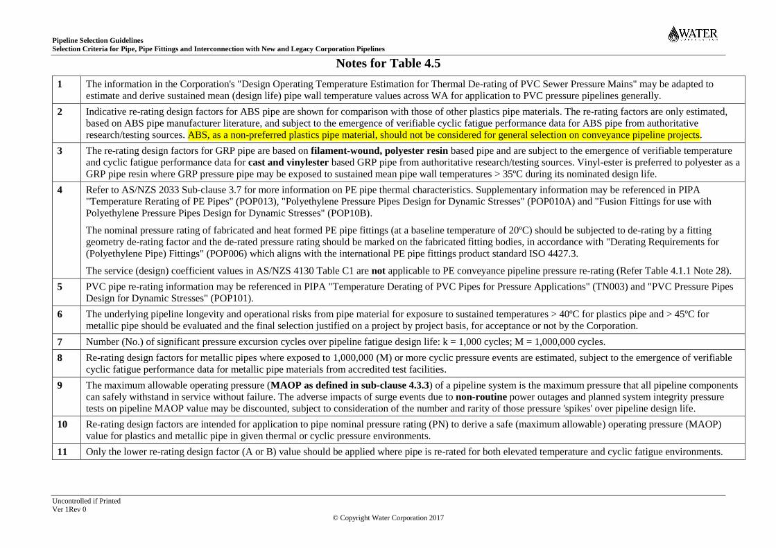
Pipeline Selection Guidelines
Selection Criteria for Pipe, Pipe Fittings and Interconnection with New and Legacy Corporation Pipelines
Uncontrolled if Printed Page 32 of 63 Ver 1Rev 0
© Copyright Water Corporation 2017
Notes for Table 4.5
1 The information in the Corporation's "Design Operating Temperature Estimation for Thermal De-rating of PVC Sewer Pressure Mains" may be adapted to
estimate and derive sustained mean (design life) pipe wall temperature values across WA for application to PVC pressure pipelines generally.
2 Indicative re-rating design factors for ABS pipe are shown for comparison with those of other plastics pipe materials. The re-rating factors are only estimated,
based on ABS pipe manufacturer literature, and subject to the emergence of verifiable cyclic fatigue performance data for ABS pipe from authoritative
research/testing sources. ABS, as a non-preferred plastics pipe material, should not be considered for general selection on conveyance pipeline projects.
3 The re-rating design factors for GRP pipe are based on filament-wound, polyester resin based pipe and are subject to the emergence of verifiable temperature
and cyclic fatigue performance data for cast and vinylester based GRP pipe from authoritative research/testing sources. Vinyl-ester is preferred to polyester as a
GRP pipe resin where GRP pressure pipe may be exposed to sustained mean pipe wall temperatures > 35ºC during its nominated design life.
4 Refer to AS/NZS 2033 Sub-clause 3.7 for more information on PE pipe thermal characteristics. Supplementary information may be referenced in PIPA
"Temperature Rerating of PE Pipes" (POP013), "Polyethylene Pressure Pipes Design for Dynamic Stresses" (POP010A) and "Fusion Fittings for use with
Polyethylene Pressure Pipes Design for Dynamic Stresses" (POP10B).
The nominal pressure rating of fabricated and heat formed PE pipe fittings (at a baseline temperature of 20ºC) should be subjected to de-rating by a fitting
geometry de-rating factor and the de-rated pressure rating should be marked on the fabricated fitting bodies, in accordance with "Derating Requirements for
(Polyethylene Pipe) Fittings" (POP006) which aligns with the international PE pipe fittings product standard ISO 4427.3.
The service (design) coefficient values in AS/NZS 4130 Table C1 are not applicable to PE conveyance pipeline pressure re-rating (Refer Table 4.1.1 Note 28).
5 PVC pipe re-rating information may be referenced in PIPA "Temperature Derating of PVC Pipes for Pressure Applications" (TN003) and "PVC Pressure Pipes
Design for Dynamic Stresses" (POP101).
6 The underlying pipeline longevity and operational risks from pipe material for exposure to sustained temperatures > 40ºC for plastics pipe and > 45ºC for
metallic pipe should be evaluated and the final selection justified on a project by project basis, for acceptance or not by the Corporation.
7 Number (No.) of significant pressure excursion cycles over pipeline fatigue design life: k = 1,000 cycles; M = 1,000,000 cycles.
8 Re-rating design factors for metallic pipes where exposed to 1,000,000 (M) or more cyclic pressure events are estimated, subject to the emergence of verifiable
cyclic fatigue performance data for metallic pipe materials from accredited test facilities.
9 The maximum allowable operating pressure (MAOP as defined in sub-clause 4.3.3) of a pipeline system is the maximum pressure that all pipeline components
can safely withstand in service without failure. The adverse impacts of surge events due to non-routine power outages and planned system integrity pressure
tests on pipeline MAOP value may be discounted, subject to consideration of the number and rarity of those pressure 'spikes' over pipeline design life.
10 Re-rating design factors are intended for application to pipe nominal pressure rating (PN) to derive a safe (maximum allowable) operating pressure (MAOP)
value for plastics and metallic pipe in given thermal or cyclic pressure environments.
11 Only the lower re-rating design factor (A or B) value should be applied where pipe is re-rated for both elevated temperature and cyclic fatigue environments.
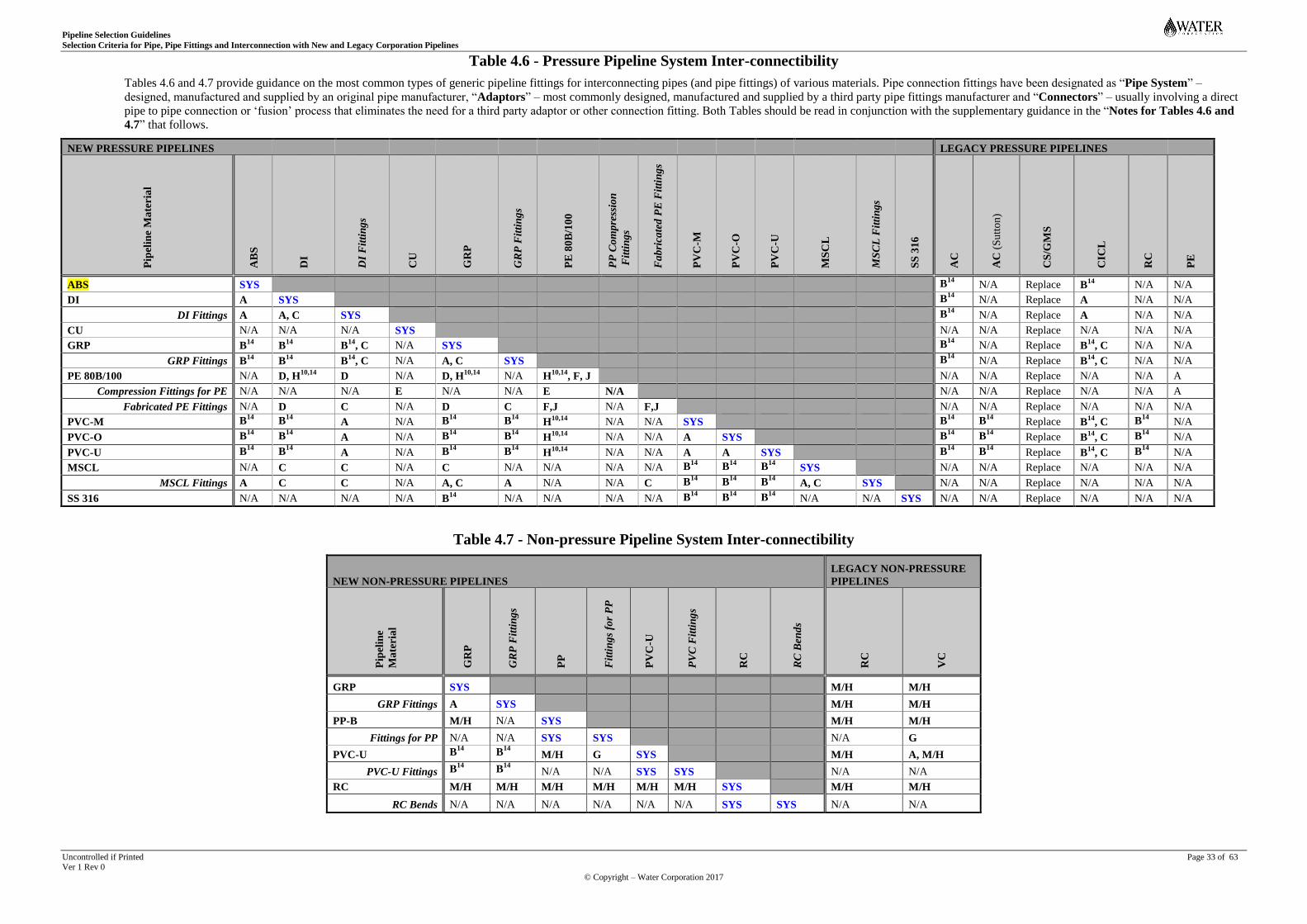
Pipeline Selection Guidelines
Selection Criteria for Pipe, Pipe Fittings and Interconnection with New and Legacy Corporation Pipelines
Uncontrolled if Printed Page 33 of 63 Ver 1 Rev 0
© Copyright – Water Corporation 2017
Table 4.6 - Pressure Pipeline System Inter-connectibility
Tables 4.6 and 4.7 provide guidance on the most common types of generic pipeline fittings for interconnecting pipes (and pipe fittings) of various materials. Pipe connection fittings have been designated as “Pipe System” –
designed, manufactured and supplied by an original pipe manufacturer, “Adaptors” – most commonly designed, manufactured and supplied by a third party pipe fittings manufacturer and “Connectors” – usually involving a direct
pipe to pipe connection or ‘fusion’ process that eliminates the need for a third party adaptor or other connection fitting. Both Tables should be read in conjunction with the supplementary guidance in the “Notes for Tables 4.6 and
4.7” that follows.
NEW PRESSURE PIPELINES LEGACY PRESSURE PIPELINES
Pip
elin
e M
ate
ria
l
AB
S
DI
DI
Fit
tin
gs
CU
GR
P
GR
P F
itti
ng
s
PE
80
B/1
00
PP
Co
mp
ress
ion
Fit
tin
gs
Fa
bri
cate
d P
E F
itti
ng
s
PV
C-M
PV
C-O
PV
C-U
MS
CL
MS
CL
Fit
tin
gs
SS
31
6
AC
AC
(S
utt
on
)
CS
/GM
S
CIC
L
RC
PE
ABS SYS B14 N/A Replace B
14 N/A N/A
DI A SYS B14 N/A Replace A N/A N/A
DI Fittings A A, C SYS B14 N/A Replace A N/A N/A
CU N/A N/A N/A SYS N/A N/A Replace N/A N/A N/A
GRP B14
B14
B14
, C N/A SYS B14 N/A Replace B
14, C N/A N/A
GRP Fittings B14
B14
B14
, C N/A A, C SYS B14 N/A Replace B
14, C N/A N/A
PE 80B/100 N/A D, H10,14
D N/A D, H10,14
N/A H10,14
, F, J N/A N/A Replace N/A N/A A
Compression Fittings for PE N/A N/A N/A E N/A N/A E N/A N/A N/A Replace N/A N/A A
Fabricated PE Fittings N/A D C N/A D C F,J N/A F,J N/A N/A Replace N/A N/A N/A
PVC-M B14 B
14 A N/A B14 B
14 H10,14
N/A N/A SYS B14 B
14 Replace B14
, C B14 N/A
PVC-O B14 B
14 A N/A B14 B
14 H10,14
N/A N/A A SYS B14 B
14 Replace B14
, C B14 N/A
PVC-U B14 B
14 A N/A B14 B
14 H10,14
N/A N/A A A SYS B14 B
14 Replace B14
, C B14 N/A
MSCL N/A C C N/A C N/A N/A N/A N/A B14 B
14 B14 SYS N/A N/A Replace N/A N/A N/A
MSCL Fittings A C C N/A A, C A N/A N/A C B14 B
14 B14 A, C SYS N/A N/A Replace N/A N/A N/A
SS 316 N/A N/A N/A N/A B14
N/A N/A N/A N/A B14 B
14 B14 N/A N/A SYS N/A N/A Replace N/A N/A N/A
Table 4.7 - Non-pressure Pipeline System Inter-connectibility
NEW NON-PRESSURE PIPELINES
LEGACY NON-PRESSURE
PIPELINES
Pip
elin
e
Ma
teria
l
GR
P
GR
P F
itti
ng
s
PP
Fit
tin
gs
for
PP
PV
C-U
PV
C F
itti
ng
s
RC
RC
Ben
ds
RC
VC
GRP SYS M/H M/H
GRP Fittings A SYS M/H M/H
PP-B M/H N/A SYS M/H M/H
Fittings for PP N/A N/A SYS SYS N/A G
PVC-U B14 B
14 M/H G SYS M/H A, M/H
PVC-U Fittings B14 B
14 N/A N/A SYS SYS N/A N/A
RC M/H M/H M/H M/H M/H M/H SYS M/H M/H
RC Bends N/A N/A N/A N/A N/A N/A SYS SYS N/A N/A
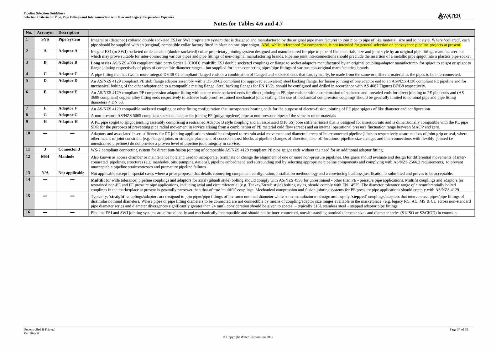
Pipeline Selection Guidelines
Selection Criteria for Pipe, Pipe Fittings and Interconnection with New and Legacy Corporation Pipelines
Uncontrolled if Printed Page 34 of 63 Ver 1Rev 0
© Copyright Water Corporation 2017
Notes for Tables 4.6 and 4.7
No. Acronym Description
1 SYS Pipe System Integral or (detached) collared double socketed ESJ or SWJ proprietary system that is designed and manufactured by the original pipe manufacturer to join pipe to pipe of like material, size and joint style. Where ‘collared’, each
pipe should be supplied with an (original) compatible collar factory fitted in place on one pipe spigot. ABS, whilst referenced for comparison, is not intended for general selection on conveyance pipeline projects at present.
2 A Adaptor A Integral ESJ (or SWJ) socketed or detachable (double socketed) collar proprietary jointing system designed and manufactured for pipe to pipe of like materials, size and joint style by an original pipe fittings manufacturer but
which may prove suitable for inter-connecting various pipes and pipe fittings of non-original manufacturing brands. Pipeline joint interconnections should preclude the insertion of a metallic pipe spigot into a plastics pipe socket.
3 B Adaptor B Long series AS/NZS 4998 compliant third party Series 2 (CIOD) 'multifit' ESJ double socketed couplings or flange to socket adaptors manufactured by an original coupling/adaptor manufacturer- for spigot to spigot or spigot to
flange jointing respectively of pipes of compatible diameter ranges - but supplied for inter-connecting pipes/pipe fittings of various non-original manufacturing brands.
4 C Adaptor C A pipe fitting that has two or more integral DS 38-02 compliant flanged ends or a combination of flanged and socketed ends that can, typically, be made from the same or different material as the pipes to be interconnected.
5 D Adaptor D An AS/NZS 4129 compliant PE stub flange adaptor assembly with a DS 38-02 compliant (or approved equivalent) steel backing flange, for fusion jointing of one adaptor end to an AS/NZS 4130 compliant PE pipeline and for
mechanical bolting of the other adaptor end to a compatible mating flange. Steel backing flanges for PN 16/21 should be configured and drilled in accordance with AS 4087 Figures B7/B8 respectively.
6 E Adaptor E An AS/NZS 4129 compliant PP compression adaptor fitting with one or more socketed ends for direct jointing to PE pipe ends or with a combination of socketed and threaded ends for direct jointing to PE pipe ends and (AS
3688 compliant) copper alloy fitting ends respectively to achieve leak-proof restrained mechanical joint sealing. The use of mechanical compression couplings should be generally limited to nominal pipe and pipe fitting
diameters < DN 63.
7 F Adaptor F An AS/NZS 4129 compatible socketed coupling or other fitting configuration that incorporates heating coils for the purpose of electro-fusion jointing of PE pipe spigots of like diameter and configuration.
8 G Adaptor G A non-pressure AS/NZS 5065 compliant socketed adaptor for joining PP (polypropylene) pipe to non-pressure pipes of the same or other materials
9 H Adaptor H A PE pipe spigot to spigot jointing assembly comprising a restrained Adaptor B style coupling and an associated (316 SS) bore stiffener insert that is designed for insertion into and is dimensionally compatible with the PE pipe
SDR for the purposes of preventing pipe radial movement in service arising from a combination of PE material cold flow (creep) and an internal operational pressure fluctuation range between MAOP and zero.
10 ▬ ▬ Adaptors and associated insert stiffeners for PE jointing applications should be designed to restrain axial movement and diametral creep of interconnected pipeline joints to respectively assure no loss of joint grip or seal, where
other means of joint constraint (e.g. flanged joints or strategic placement of concrete thrust blocks at pipeline changes of direction, take-off locations, pipeline size changes and interconnections with flexibly jointed i.e
unrestrained pipelines) do not provide a proven level of pipeline joint integrity in service.
11 J Connector J WS-2 compliant connecting system for direct butt-fusion jointing of compatible AS/NZS 4129 compliant PE pipe spigot ends without the need for an additional adaptor fitting.
12 M/H Manhole Also known as access chamber or maintenance hole and used to incorporate, terminate or change the alignment of one or more non-pressure pipelines. Designers should evaluate and design for differential movements of inter-
connected pipelines, structures (e,g, manholes, pits, pumping stations), pipeline embedment and surrounding soil by selecting appropriate pipeline components and complying with AS/NZS 2566.2 requirements, to prevent
unacceptable pipeline strains/stresses and premature pipeline failures.
13 N/A Not applicable Not applicable except in special cases where a prior proposal that details connecting component configuration, installation methodology and a convincing business justification is submitted and proves to be acceptable.
14 ▬ ▬ Multifit (or wide tolerance) pipeline couplings and adaptors for axial (gibault style) bolting should comply with AS/NZS 4998 for unrestrained - other than PE - pressure pipe applications. Multifit couplings and adaptors for
restrained non-PE and PE pressure pipe applications, including axial and circumferential (e.g. Teekay/Straub style) bolting styles, should comply with EN 14525. The diameter tolerance range of circumferentially bolted
couplings in the marketplace at present is generally narrower than that of true ‘multifit’ couplings. Mechanical compression and fusion jointing systems for PE pressure pipe applications should comply with AS/NZS 4129.
15 ▬ ▬ Typically, ‘straight’ couplings/adaptors are designed to join pipes/pipe fittings of the same nominal diameter while some manufacturers design and supply ‘stepped’ couplings/adaptors that interconnect pipes/pipe fittings of
dissimilar nominal diameters. Where pipes or pipe fitting diameters to be connected are not connectible by means of coupling/adaptor size ranges available in the marketplace (e.g. legacy RC, AC, MS & CU across non-standard
pipe diameter series and diameter divergences significantly greater than 24 mm), consideration should be given to special – typically 316L stainless steel – stepped adaptor pipe fittings.
16 ▬ ▬ Pipeline ESJ and SWJ jointing systems are dimensionally and mechanically incompatible and should not be inter-connected, notwithstanding nominal diameter sizes and diameter series (S1/ISO or S2/CIOD) in common.

Pipeline Selection Guidelines
Selection Criteria for Pipe, Pipe Fittings and Interconnection with New and Legacy Corporation Pipelines
Uncontrolled if Printed Page 35 of 63 Ver 1 Rev 0
© Copyright – Water Corporation 2017
APPENDIX A
Table A1 Pipeline Material, Engineering and Jointing Characteristics
Pip
e M
ate
ria
l1
Acr
on
ym
Ref
eren
ce
Sp
ecif
ica
tio
n3
Dia
met
er S
erie
s (S
1-
ISO
/Met
ric
or
S2
- C
IOD
)5
Dia
met
er R
an
ge
(DN
)1
Pre
ssu
re R
ati
ng
(P
N)1
0 o
r
No
n-p
ress
ure
(N
P)
Sti
ffn
ess
Ra
tin
g11
Sta
nd
ard
Pip
e L
eng
th (
m)
Pip
e C
oa
tin
g S
pec
ific
ati
on
45
( P
E o
r F
BE
22)
Pip
e L
inin
g S
pec
ific
ati
on
45
(CL
or
FB
E23)
Pip
e J
oin
tin
g S
pec
ific
ati
on
25,
28
Un
rest
rain
ed
(UR
)
or
Res
tra
ined
(R
)44
NEW PIPES
Acronitrile Butadiene Styrene ABS AS/NZS 3518 S2 AS/NZS 3518 Table 3.4 (A & B) 12, 15 & 20 Refer Table 4.2 6 UR
DN 100 to 7506 None None Note 26
Cast Ductile Iron Pipe DI AS/NZS 2280 S2 DN 300 to 750 16 (FLCL12), 20 & 35 Refer Table 4.4 5 Uncoated CL Notes 26, 30 UR
Pipe Fittings DI SPS 106 S2 AS/NZS 2280 16/3513 N/A N/A FBE FBE Note 26, 30 UR
Copper CU AS 1432 Type A
DN 20 to 25 AS 1432 Table C2 N/A 3, 6 None None Notes 33, 34 UR
AS 1432 Type A DN 32 to 200 AS 1432 Table C2 N/A 3, 6 None None Note 33 UR
Glass reinforced plastic (Pressure) GRP SPS 130 S2 DN 375 to 2400 16 to 35 SN 10 to 20 6, 12 None None Note 26 UR
Glass reinforced plastic (Non-pressure) GRP SPS 130 S2 DN 375 to 2400 NP (PN 3 to 6)14 SN 10 to 20 6, 12 None None Note 26 UR
Pipe Fittings GRP SPS 130 As pipe To match pipe To match pipe SN 10 N/A None None Note 26 UR
Polyethylene PE 80B SPS 125 S1 DN 125 to 6307 12.5, 16 Refer Table 4.2 6, 12 None None Note 32 R
PE 100 SPS 125 S1 DN 125 to 6307 12.5, 16 Refer Table 4.2 6, 12 None None Note 32 R
Compression Pipe Fittings PP-B SPS 125 S1 DN 25 to 63 16 > Pipe SN N/A None None Note 31 R
Fabricated Pipe Fittings PE SPS 125 S1 DN 125 to 6307 Table 4.515 > Pipe SN N/A None None Note 32 R
Polypropylene43 (Non-pressure) PP-B SPS 125 S1 DN 375/400 to 630 NP SN 10 6 None None Note 26 UR
Pipe Fittings GRP/PVC SPS 125 S1 DN 375/400 to 630 NP > Pipe SN N/A None None Note 26 UR
Polyvinyl Chloride Modified PVC-M SPS 116 S2 AS/NZS 4765 Table 4.2 12, 16 & 20 Refer Table 4.2 6 None None Note 26 UR
DN 100 to 375
Biaxial Molecular Oriented PVC-O SPS 117 S2 AS/NZS 4441 Table ZZ1A S2 12, 16 & 20 Refer Table 4.2 6 None None Note 26 UR
DN 100 to 375
Unplasticised (Pressure) PVC-U SPS 115 S2 AS/NZS 1477 Table 4.2 (B) 12, 16 & 20 Refer Table 4.2 6 None None Note 26 UR
DN 100 to 375
Unplasticised (Non-pressure) PVC-U AS/NZS 1260 (Plain Wall/Sandwich) S1 DN 10026 NP SN 6, 10, 1627 6 None None Note 26 R
AS/NZS 1260 (Structured/Profile) S1 DN 10026 NP SN 8, 1627 6 None None Note 26 R
AS/NZS 1260 (All Structural Forms) S1 DN 150 to 30026 NP SN 8, 1627 6 None None Note 26 R
AS/NZS 1260 (All Structural Forms) S1 DN 37526 NP SN 8, 1627 6 None None Note 26 UR
Pipe Fittings PVC-U AS/NZS 1260 S1 DN 100 to 37526 NP SN 627 N/A None None Note 26 As pipe
Reinforced Concrete (Non-pressure) RC AS/NZS 4058 N/A DN 750 to 2250 NP Load Classes 4, 6, 8 & 10 2.44 Uncoated Plastics lined25 Note 35 UR
Polymer Resin Concrete2 (Non-pressure) RA ISO 18672-1 N/A DN 800 to 2000 NP 2720 to 13830 kN44 3 None None UR
Mild (Carbon) Steel MS(CL) SPS 100 S1 DN 100 to DN 1400 68 - 28 (Table 4.3) Refer Table 4.3 6, 12 PE to AS 4321 CL to AS 1281 Notes 26,/36 UR/R
Pipe Fittings MS(CL) DS 654 S1 DN 100 to DN 1400 16, 21 & 35 N/A PE to AS 4321 CL to AS 1281 Note 36 R
Stainless Steel Tube SS 316 ASTM A312 S1 DN 20 to 200 10S: 254 to 4216 SN 10000 to 8516 6 None None Note 36 R
40S: 369 to 9316 SN 28000 to 95016
Stainless Steel Pipe SS 316 ASTM A312 S1 DN 250 to 6008 10S: 38 to 2516 SN 60 to 1816 None None Note 36 R
40S: 84 to 3816 SN 700 to 6516

Pipeline Selection Guidelines
Selection Criteria for Pipe, Pipe Fittings and Interconnection with New and Legacy Corporation Pipelines
Uncontrolled if Printed Page 36 of 63 Ver 1Rev 0
© Copyright Water Corporation 2017
Pip
e M
ate
ria
l1
Acr
on
ym
Ref
eren
ce
Sp
ecif
ica
tio
n3
Dia
met
er S
erie
s (S
1-
ISO
/Met
ric
or
S2
- C
IOD
)5
Dia
met
er R
an
ge
(DN
)1
Pre
ssu
re R
ati
ng
(P
N)1
0 o
r
No
n-p
ress
ure
(N
P)
Sti
ffn
ess
Ra
tin
g11
Sta
nd
ard
Pip
e L
eng
th (
m)
Pip
e C
oa
tin
g S
pec
ific
ati
on
45
( P
E o
r F
BE
22)
Pip
e L
inin
g S
pec
ific
ati
on
45
(CL
or
FB
E23)
Pip
e J
oin
tin
g S
pec
ific
ati
on
25,
28
Un
rest
rain
ed
(UR
)
or
Res
tra
ined
(R
)44
LEGACY PIPES CTS or HDS Rating17
Asbestos Cement AC AS 1711 S2 DN 58 (WA only) Class C/D/E = PN9/12/15 23.5 Mpa (CTS11) 4 Uncoated Unlined Note 37 UR
(Mazza/Magnani processes 1951 to 1975) DN 80 to 600; 4
DN 75 to 600 4
DN 75 to 300 4
Special High Strength Pipe AC AS A41 & AS 1711 S2 Project specific only PN 14/16 (DN 200 to 600)18 Cl. C Codes 28/3118 4 Uncoated Unlined Note 37 UR
PN 18/20 (DN 200 to 300)18 Cl. D Codes 28/3118 4
Asbestos Cement
(Sutton process 1929 to 1951) AC None N/A DN 100, 150 Not recorded Not nominated19 3.35, 4 Uncoated Unlined Note 37 UR
Carbon steel (black iron)24 CS AS A125 S1 DN 20 to DN 150 Not recorded Not nominated19 6.5 Uncoated Unlined Note 38 R
Galvanised mild steel (tube)24 GMS AS B105, AS 1074 S1 DN 20 to DN 150 25 (5 MPa proof test) Not nominated19 6.5 Galvanized24 Galvanized24 Note 38 R
Grey Cast Iron (1965 to circa 1986) CI(CL) AS A145, AS 2544 & AS/NZS 2544 S2 DN 80 to DN 1200 PN 14, 21 Not nominated19 5.5 Uncoated Cement Lined24 Notes 39, 40 UR
DN 80 to DN 600 PN 3513
Reinforced Concrete (Pressure) RC AS A124/AS 1392 Tables D1/D2 N/A DN 100 to 300 50 to 180 PSI (Table D2) Not nominated19 1.83, 2.44 Uncoated Unlined Note 39 UR
DN 300 to 900 (345 to 1241 KPa)
Reinforced Concrete (Non-pressure) RC AS A35/AS 1342 N/A DN 450 to 900 NP Load classes X, Y, Z20 1.83, 2.44 Uncoated Unlined Note 41 UR
Table VI AS A35
Vitreous Clay (Non-pressure) VC AS A164 N/A DN 150 to 375 NP AS A164 Table 1 0.91 to 1.83 None None Note 41 UR
AS 1741 AS 1741 Table 3.1
Polyethylene LDPE, HDPE, MDPE AS K119/AS 1159 S1 DN 25 to 110 (Classes) 9, 12 3, 5 & 8 Mpa21 6 & 100 (coil) None None Note 42 R

Pipeline Selection Guidelines
Selection Criteria for Pipe, Pipe Fittings and Interconnection with New and Legacy Corporation Pipelines
Uncontrolled if Printed Page 37 of 63 Ver 1Rev 0
© Copyright Water Corporation 2017
Notes for Table A1
1 Pipeline selection, design and specification should be based on the configuration, engineering performance, installibility of and operational constraints on the supplied pipe, pipe fittings and jointing systems, together with the market
availability (Refer Table 4.1.1) of all interconnected components.
2 Polymer (polyester) or resin aggregate (RA) concrete pipe is included because of its particular suitability for pipe jacking applications. Acceptable RA pipe product standards include EN 14636-1, DIN 54815-1/2, ASTM D6783-05 as
well as ISO 18672-1. The values under the "Stiffness" heading describe its working compressive strength in kilonewtons.
3 A pipeline product reference specification can include a Corporation developed strategic product standard (SPS), a national - including WSAA - or other (e.g. overseas) product standard or specification that has been agreed as fit for
purpose by the Corporation. Where a pipe reference specification (e.g. SPS 125) nominates pipe striping or jacket colour, the over-riding intent is to ensure that pipe for drinking water, non-drinking water, wastewater and drainage
applications is coloured or striped light blue, purple, cream and black respectively, notwithstanding colour shade or hue variations specified by different industry sectors e.g. WSAA, PIPA and individual water utilities.
4 Appendices A and B of SPS 100 specify enhanced requirements for steel pipe in seawater and brine applications. DS 65 shows standard shape, configuration and weld arrangements for mild steel (MS) pipe fittings. Welding work
requirements are specified in "Welding Specification - Metal Arc Welding" WS-1.
5 Some background information on Australian pipe alignment with imperial cast iron pipe (CIOD or Series 2) diameters, in the face of European trends toward the smaller metric (ISO or Series 1) pipe sizes, is provided in Section 3.
6 Acrylonitrile butadiene styrene (ABS) pipelines are not listed in Corporation records of conveyance assets, notwithstanding that ABS process pipework forms part of some treatment plants. ABS is a non-preferred plastics pipe material
that should not, at present, be considered for general selection on conveyance pipeline projects.
7 Projects for which PE pipeline sizes larger than DN 630 may be under consideration need to be supported by a prior operability & maintainability feasibility case, given the future service constraints and risk to the Corporation’s
Operating Licence associated with lengthy pipeline outages due to the logistics of large PE pipe fusion jointed repairs and unavailability of large AS/NZS 4129 compliant axially restrained mechanical joint couplings for PE pipe.
8 Corporation asset records do not acknowledge any stainless steel (SS) conveyance pipelines, notwithstanding that some treatment plants may include SS process pipework. Selection of SS pipe should be supported by a rational whole-
of-business justification.
9 Refer to Table 4.1.1 for high level general guidance on market availability considerations, prior to selecting pipeline components.
10 Pipe nominal pressure (PN) is rated for a baseline temperature of 20ºC. Its actual (allowable) pressure rating will decrease proportionately as mean pipe wall temperature rises above 20ºC. Refer Table 4.5
11 Pipe stiffnesses (resistances to deflection) are defined in terms of a stiffness number (SN), hydrostatic design strength (HDS) in MPa, structural load class e.g. RC pipe or circumferential tensile strength (CTS) e.g. AC pipe
12 The pressure rating of special flanged class (FLCL) DI pipe is determined by the (screwed) flange design as defined in AS/NZS 2280
13 The standard pressure rating for 'traditional' DI pipe fittings in accordance with AS/NZS 2280 is PN 35 except, as provided for in the standard, PN 16 'lightweight' fittings that are generally used in in smaller pipeline sizes (DN 100-250)
e.g. for water reticulation applications.
14 Non-pressure GRP pipe, albeit theoretically rated for internal hydraulic pressures between PN 3 and PN 6 to accommodate field test and operational surcharge pressures, is not intended for pressure applications.
15 Refer to Table 4.5 (Note 4) for guidance on the geometry de-rating of the nominal pressure rating of fabricated polyethylene pipe fittings and marking of the de-rated pressure rating on the fittings prior to their supply into projects.
16 The SS tube and pipe pressure rating and estimated stiffness values shown are indicative only, for comparison with the values for other pipe materials
17 Asbestos cement (AC) pipe pressure classes that applied at time of installation are likely to be lower today due to the impacts of fluid pH and other factors on the cement binder over time.
18 AC pipe special pressure classes (Codes 28 & 31) were designed to achieve a minimum circumferential tensile strength of 28 & 31 MPa respectively as compared with 23 MPa for standard AC pipe.
19 Stiffness values were not nominated for legacy AC, CS/GMS, CI and RC pipe, being rigid (not plastics) pipe.
20 Legacy RC pipe load classes X, Y & Z were equivalent to AS/NZS 4058 load or strength classifications 2, 3 & 4 respectively.
21 The minimum required long term strength (MRS) of legacy PE pipe - 3 to 8 Mpa - compares with 10 MPa for PE 100 to AS/NZS 4130
22 The pipe coating designations shown - PE and FBE - mean AS 4321 compliant MDPE and AS/NZS 4158 compliant fusion bonded epoxy respectively. Consideration of alternative coating systems e.g. AS/NZS 2280 compliant metallic
zinc coating or polyurethane coating should be supported by a prior pipe and coating performance evaluation that assures corrosion protection longevity and maintainability.
23 The pipe lining designations shown mean FBE - AS/NZS 4158 compliant fusion bonded epoxy and CL or cement mortar lining - AS/NZS 2280 compliant for DI pipe and AS 1281 compliant for MSCL pipe. Consideration of
alternative lining systems e.g. AS 4321 compliant MDPE lining, AS/NZS 2280 compliant calcium aluminate cement mortar lining and cement lining seal coat should be supported by a prior lining (and lining seal coat as appropriate)
evaluation that assures coating longevity and maintainability.
24 Legacy carbon steel (CS or black iron) and galvanised mild steel (GMS) pipe tended to have been respectively bitumen coated and galvanised in accordance with AS 1650. Grey iron pipe tended to have been coated with bitumen and
cement mortar lined in accordance with As 2544. Legacy 'iron' pipelines - particularly those smaller than DN 100 should be retired and replaced wherever cost effective project opportunities that involve them arise.
25 Non-pressure RC pipe should, for longevity (fully functional for > 25 years), be plastics lined in accordance with a proven lining specification acceptable to the Corporation - particularly for wastewater applications.
26 An integral or detachable unrestrained ESJ or SWJ jointing system that is generally fixed or fitted to the pipe or pipe fitting at the time of supply. Defined as "SYS" or "Adaptor A" respectively in Tables 4.6 and 4.7. Solvent
weld/cement jointing for sizes < DN 300 should be in accordance with AS 3879 and WS-2. PVC pipe sizes > 300 should be elastomerically seal jointed, to address the consistently elevated temperature conditions - and the consequent
impracticability of large diameter SWJ jointing - in WA climatic conditions. Integral pipeline jointing – including elastomeric seal –components should be supplied and/or the jointing compatibility and performance should be validated
by the original manufacturer or supplier of the pipeline components to be mated and jointed.
27 AS/NZS 1260 sets out requirements for DN 100 non-pressure PVC-U pipe in plain or sandwich form with stiffness values of SN 6 or 10 and in profile form with a stiffness value of SN 8. It also sets out requirements for DN 150 to 375
non-pressure PVC-U pipe in plain, sandwich or profile form with stiffness values of SN 8 or 16. Non-pressure PVC-U pipelines with a stiffness rating requirement < SN 16 may safely incorporate AS/NZS 1260 compliant injection
moulded pipe fittings with a nominal stiffness rating of SN 6 because the jointed pipeline system is manufactured to provide a composite stiffness no lower than that of the inter-connected pipe.

Pipeline Selection Guidelines
Selection Criteria for Pipe, Pipe Fittings and Interconnection with New and Legacy Corporation Pipelines
Uncontrolled if Printed Page 38 of 63 Ver 1Rev 0
© Copyright Water Corporation 2017
Notes for Table A1 (continued)
28 Flexible pipe jointing systems may not be assumed to have significant angular displacement capacity. Most PVC pressure pipe jointing systems are non-deflection, albeit with a 1° deflection tolerance without loss of seal performance.
Joint angular deflection capacity can vary considerably across pipe sizes and from one pipe manufacturer to another. Designers and specifiers, prior to specifying pipeline joint angular configurations, should determine the joint angular
deflection limitations to be applied on project drawings, by specific reference to the manufacturers (or suppliers) of the proposed pipes and jointing systems.
29 Flexible joint components (e.g. integral sockets, detachable collars and couplings) should incorporate elastomeric (or 'rubber ring') seals (ESJ or RRJ) in accordance with AS 1646/AS 681. Seals for wastewater applications should be
SBR as defined in AS 1646 (Refer to the Notes for Table A2).
30 Pipe/pipe fitting joint flanges should be generally supplied as integral (not screwed) flanges in accordance with AS/NZS 2280 and AS 4087 e.g. "Adaptor C" as defined in Table 4.6.
31 Mechanical compression (fittings) jointing systems should be in accordance with AS/NZS 4129 Section 2.
32 Refer to “Notes for Tables 4.6 and 4.7” for important guidance on the requirement to stiffen PE pipeline joint spigots by means of SS stiffener inserts (supplied by the PE pipe/pipe fitting supplier) where they are to be mechanically
(non-fusion) jointed (e.g. “Adaptor A/H). Fusion jointed (using butt-fusion and electro-fusion) fitting systems should be in accordance with AS/NZS 4129 and should be undertaken only by qualified thermoplastics welders who have
been duly accredited and have demonstrated sufficient fusion welding experience in accordance with the requirements of WS-2.
33 Welded jointing (Silver Brazing Alloy) system in accordance with AS 1167.1 Table 1 (< 0.05% cadmium) or AS 1167.1 Table 2 (> 5% silver).
34 Mechanical press-fit jointing system (e.g. Viega Propress or other system acceptable to the Corporation), using authorised system equipment, tooling and installation instructions.
35 Integral flexible jointing system that is generally supplied with the pipe, with 'belled' sockets DN < 1800 and in-wall sockets DN > 1800 as defined for "SYS" in Table 4.7.
36 Steel weld jointing (e.g. WJ-PE) systems for steel pipes and fittings should comply with the requirements of WS-1 (including AS 4041), DS 60 and DS 65. Designers should calculate steel pipeline MAOP in accordance with the
guidance in Table 4.3, having particular regard to limited strength joint configurations including weld restrained elastomeric seal (RRJ-WR) joints.
37 Detachable flexible (rubber ring) seal jointing system to the same performance standard as inter-connectible AS B26 CI pipe fittings and - from 1975 - AS 1646 compliant joint seals supplied as an integral part of pipe supply.
38 Threaded BSP, and later, AS 1722.1 steel socket coupling system, with applied thread sealing compounds
39 Round rubber ring jointing system, except most road/bridge crossings which, historically, were lead & hemp yarn jointed and cement mortar/yarn repaired
40 Flanged jointing system in accordance with AS B52 and, later AS 4087, supplied as an integral flange on the pipe.
41 Rigid cement mortar and, circa 1960's, flexible rolling or sliding rubber ring jointing system to AS A139 and, later, AS 1646
42 Mechanical compression (fittings) jointing system in accordance with AS 1460.
43 Polypropylene corrugated profile walled pipe and associated inter-connectible fittings (to AS/NZS 5065) are intended for non-pressure and relatively shallow applications. Design guidance for polypropylene structured wall pipe is
provided in PIPA Guideline POP015
44 Unrestrained (UR) means an axially unrestrained (typically. flexible) jointing system. Restrained (R) means an axially restrained jointing system by means of integral flanged (e.g. DI, MS, SS) in accordance with DS 38-02, fusion
welding (e.g. PE, MS & SS) in accordance with WS-2 & WS-1 respectively, solvent cement welding (e.g. non-pressure PVC) in accordance with AS/NZS 2032, compression friction grips (e.g. small bore PE & Cu) and threaded (e.g.
small bore Cu & iron/steel).
45 Pipeline materials, coatings and linings should be selected to provide the required asset longevity in accordance with guidance in Table A2 for the investigation and identification of potential risks from exposure to corrosive products
and contaminants.

Pipeline Selection Guidelines
Selection Criteria for Pipe, Pipe Fittings and Interconnection with New and Legacy Corporation Pipelines
Uncontrolled if Printed Page 39 of 63 Ver 1 Rev 0
© Copyright – Water Corporation 2017
Table A2 Pipeline Longevity, Installation and Testing Characteristics18
Pip
e M
ate
rial/
Acr
on
ym
Da
rmst
ad
t A
bra
sio
n W
ear
per
10
0,0
00
cy
cles
2
Res
ista
nce
to
Corr
osi
on
&
Co
nta
min
an
ts4,
5,
6
Co
effi
cien
t o
f T
her
mal
Ex
pa
nsi
on
(10
–5 m
/m p
er °
C)
Tra
nsi
ent
(Su
rge)
Pre
ssu
re
Ca
pa
bil
ity
Pip
elin
e S
eal
Su
ita
bil
ity
fo
r
Va
cuu
m S
yst
ems
Em
bed
men
t &
In
stall
ati
on
Ref
eren
ce S
pec
ific
ati
on
Fie
ld A
ccep
tan
ce T
est
Sp
ecif
ica
tio
n
ABS3 0.3-0.6 High
6 10.1 < MAOP SWJ, ESJ
13 AS/NZS 3690 AS/NZS 3690 Sub-clause 7.2.3 and
AS/NZS 2566.2 Sub-clauses 6.3.4.2 and M5
DICL7, 8
1-2 Limited6 1.1 < MAOP ESJ
13 AS/NZS 2566 & WSAA TN3 AS/NZS 2566 Sub-clauses 6.3.4.1 and M4
CU N/A Limited6 1.7 < 1.2 x AOP
11 N/A AS 4809 AS/NZS 3500.1 Sub-clause 16.3.1
15
GRP3 (Pressure) 0.2-0.8 High
6 2.5-3.0 < MAOP ESJ
13 AS/NZS 2566 AS/NZS 2566 Sub-clauses 6.3.4.1 and M4
GRP3 (Non-pressure) 0.2-0.8 High
6 2.5-3.0 N/A N/A AS/NZS 2566 Sub-clauses 6.4 and N4
PE 80B3 0.4-0.6 High
6 18 < MAOP SDR 9 Welded
14 AS/NZS 2033 AS/NZS 2033 Clause 7.2 including Sub-clause 7.2.4
16
PE 1003 0.2-0.5 High
6 20 < MAOP SDR < 11, Welded
14 AS/NZS 2033 AS/NZS 2033 Clause 7.2 including Sub-clause 7.2.4
16
Fabricated Fittings (PE3) N/A High
6 N/A < MAOP
12 SDR < 11, Welded
14 AS/NZS 2033 As part of Pipeline
PP3 (Non-pressure) 0.4-1 High
6 15 N/A N/A AS/NZS 2566 AS/NZS 2566 Sub-Clauses 6.4 and N4
PVC-M (Pressure)3 0.1-0.3 High
6 7 < MAOP
10 SWJ, ESJ
13 AS/NZS 2032 AS/NZS 2032 Sub-clause 7.2 and AS/NZS 2566 Sub-clauses 6.3.4.1 and M4,
for hydrostatic acceptance;
AS/NZS 2566.2 Sub-clauses 6.5 and Appendix O, for deflection acceptance PVC-O (Pressure)
3 0.1-0.3 High
6 7 < PFA (MAOP)
10 SWJ, ESJ
13 AS/NZS 2032
PVC-U (Pressure)3 0.1-0.3 High
6 7 < WP (MAOP)
10 SWJ, ESJ
13 AS/NZS 2032
PVC-U3 (Non-pressure) 0.1-0.3 High
6 7 N/A N/A AS/NZS 2032 AS/NZS 2032 Sub-Clause 7.3
RC7 (Non-pressure) 2-2.5 Limited
6 1 N/A N/A AS/NZS 3725 CPAA
17
RA1 (Non-pressure) < 0.5 High
6 N/A N/A BS EN 1610 BS EN 1610
17
MSCL7, 8
1-2 Limited6 1.2 < MAOP N/A AS/NZS 2566 AS/NZS 2566 Sub-clauses 6.3.4.1 and M4 - zero make-up water allowance
SS 3169 N/A Limited
6 1.5 < MAOP N/A AS/NZS 2566 AS/NZS 2566 Sub-clauses 6.3.4.1 and M4 - zero make-up water allowance

Pipeline Selection Guidelines
Selection Criteria for Pipe, Pipe Fittings and Interconnection with New and Legacy Corporation Pipelines
Uncontrolled if Printed Page 40 of 63 Ver 1 Rev 0
© Copyright – Water Corporation 2017
Notes for Table A2
1 Resin Aggregate (RA) pipe is better known as polymer concrete and is generally best suited to trenchless (jacked pipe) applications
2 The Darmstadt abrasion wear values shown are only broadly indicative of the comparative scale of the internal abrasion wear potential of different pipe materials. Reliable measured abrasion resistance test data should be provided by the
respective pipe manufacturers. DICL and MSCL values reflect lining rather than substrate or structural (DI, MS) pipe material wear.
3 ABS is a non-preferred conveyance pipeline material, at present. Some plastics pipe materials (PE and PVC) can be permeated by (usually petroleum based) volatile and aromatic hydrocarbons and organic solvents. In particular:
PVC tensile strength is reduced by exposure to esters, ketones, ethers and aromatic or chlorinated hydrocarbons.
PE strength and structural performance is susceptible to degradation by strong oxidants including halogens and inorganic acids and is known to be prone to permeation of BTEX (benzene, toluene, ethylbenzene & xylene) with
consequent 'tainting' of PE pipe contents which, in the case of drinking water, would be unacceptable. PE 100 - but not PE 80B - is the polymer of choice in the marketplace supplying the water industry.
GRP/FRP (polyester resin based) susceptibility to ozone, alkaline conditions (where pH < 10.5), chlorinated hydrocarbons, nitric acid and concentrated hydrofluosilicic acid.
4 Refer to AS 1646/AS 681 for material composition, technical standards and compliance information on elastomeric seal materials. The longevity performance of pipeline joint seal materials can be reduced significantly as follows:
EPDM - exposure to strong acids, alkalis, mineral oils, solvents and aromatic hydrocarbons;
NR & SBR - exposure to ozone, strong acids, fats, mineral oils, greases and most hydrocarbons;
CR - exposure to strong oxidising acids, esters, ketones and chlorinated, aromatic & nitro hydrocarbons;
NBR - exposure to ozone, ketones, esters, aldehydes and chlorinated & nitro hydrocarbons.
5 Notwithstanding default corrosion & contaminants resistance rate guidance shown in this Table, the potential risks from internal and external exposure to corrosive products and contaminants should be investigated, identified and
addressed by selecting pipeline (including flexible joint seal) components, materials, coatings and linings by reference to the geological, hydrogeological, chemical corrosivity and (soil) electrical resistivity characteristics of the pipeline
environment as appropriate. Investigations should reference manufacturer and relevant scientific data related to the corrosion and chemical resistance characteristics of pipeline components. Guidance on the “Investigation and identification
of acid sulfate soils and acidic landscapes” is available from the Department of Environment and Conservation. Guidance on the risk based management of acid sulfate soils. Asset installation and dewatering work in the vicinity of acid
sulfate soils may be referenced in “Water Corporation Acid Sulfate Soil and Dewatering Management Strategy” (aquaDOC #441876).
6 Guidance for protecting drinking water pipelines in contaminated ground is given in the UK Foundation for Water Research report “Laying Potable Water Pipelines in Contaminated Ground” available for purchase at www.fwr.org.
7 Unprotected concrete and GP cement based pipe linings are unsuitable for extended exposure to aggressive fluids and corrosive gases and should not be selected for
non-pressure wastewater and drainage applications with any potential for exposure to acidic, corrosive and trade/commercial waste fluids or gas environments;
exposure to negative pressures or to fluid flows bearing erosive/abrasive matter over pipeline design lifetime;
pressure wastewater applications where operating pressures could routinely fall below +10 KPa during pipeline design life;
Concrete and cement mortar pipeline surfaces should be protected against contact with aggressive/corrosive environments. Portland (GP) Cement based concrete surfaces can be thermo-plastically lined to prevent direct contact with
aggressive materials. Degradation of unprotected GP cement mortar lining alkalinity by internal carbonation, chloride attack or pH level fluctuation over time can be mitigated by using acceptable corrosion inhibiting coatings or corrosion
resistant base ingredients e.g. calcareous aggregate, calcium aluminate and sulfate resistant cement, as appropriate.
8 Ferro-metallic pipeline components and associated lining & coatings systems and treatments should be selected and designed to protect them against internal and external exposure to corrosive chemical, gaseous and active microbial
environments. DS 95 specifies protection requirements to secure & maintain metallic pipeline longevity. Appendices A and B of SPS 100 specify enhanced requirements for steel pipe in seawater and brine applications.
9 Notwithstanding a pitting resistance equivalent number (PREN) > 22, SS 316 pipe and tube material can be susceptible to crevice and pitting corrosion where:
in contact with fluids containing high (250 to 1000 mg/L) chloride levels - particularly (even at the lower chloride level values) - in the presence of oxidizing agents;
pipeline fluid velocities are routinely low (< 0.75 m/s) and where bacterial slimes and sediments can reside and nourish microbial growth activity;
pipeline borne fluid pH levels are between 4 and 10 (SS de-passivation range). Lower pH (< 4) levels are particularly corrosive and higher levels (> 10) are not significantly corrosive.
entrained gas and air/oxygen levels are significantly high e.g. where the pipeline fluid is subject to mechanical aeration;
the integrity of pipeline and joint welds may be inferior (e.g. porous, creviced or cracked);
pipeline components are supplied with adhesive information or identifying labels attached to the SS material surface.
Welded pipeline components should be made from 316L SS material as a minimum or, where a number of potentially corrosive agents are present, 'super-duplex' SS material with a PREN value > 40.
10 The terminology for maximum allowable operating (or working) pressure (MAOP) for PVC pipe differs in different Australian product standards, being "WP" in AS/NZS 1477, "MAOP" in AS/NZS 4765 and "PFA" in AS/NZS 4441.
11 AOP for copper pipe is the allowable steady state pressure excluding dynamic pressure excursions (surges) i.e. the safe working pressure as defined in AS 1432 Table C2
12 Polyethylene pipe fittings should be selected and supplied on the basis of declared pressure rating (i.e. guaranteed MAOP – at 20ºC) which should be expressly and clearly marked on each fitting. The marking of standard dimension ratio
(SDR) alone on a PE pipe fitting is not an acceptable nor safe basis for assuming or presuming a particular operating pressure rating in any application. Declared pressure rating values should be supported by documented records of fitting
design basis calculations and pressure testing by accredited (e.g. NATA) testing facilities in accordance with AS/NZS 4129 and POP006 "Derating Requirements for Fittings" as appropriate to moulded and fabricated fitting geometry (as
defined in POP 006). Fabricated PE pipe fittings include those manufactured in various geometric configurations from AS/NZS 4130 compliant pipe segments, sweep bends, pull-out tees, transition pieces and spigot ends - all as defined in
POP 006. PE pipe fitting pressure de-rating should be in accordance with the rules in POP 006 (including called up ISO 4427.3 requirements).
13 The acceptability of elastomeric seal joints (ESJ) for vacuum pipeline applications should be subject to written confirmation by the pipe joint manufacturer of their safe sealing performance capability for exposure to full vacuum (-100KPa)
pressures, given that pipe product standards generally specify joint seal performance testing for pressure values no lower than -80KPa.
14 The structural stiffness selected for PE pipeline components should safely sustain negative pressures and resist buckling in vacuum applications. They should be welded in accordance with the requirements of WS-2.
15 Site test pressure for Type A copper pipe should not exceed the Pt values shown for Type A in AS 1432 Table C2 (e.g. < 1.5 MPa for DN < 150). The selection/use of copper pipe is generally limited to property services applications.
16 PE pipe (particularly in larger diameters) should not be selected for pipeline sections that may underlie significant structures or built assets whose integrity or stability may be compromised by significant viscoelastic expansion and
contraction movement arising from pipeline internal pressure fluctuations in service and from PE pipeline field pressure testing operations

Pipeline Selection Guidelines
Selection Criteria for Pipe, Pipe Fittings and Interconnection with New and Legacy Corporation Pipelines
Uncontrolled if Printed Page 41 of 63 Ver 1 Rev 0
© Copyright – Water Corporation 2017
17 Field acceptance testing of RC pipe should be in accordance with Concrete Pipe Association of Australasia (CPAA) "Field Testing of Concrete Pipelines and Joints". Field acceptance testing of RA pipe should be in accordance with BS
EN 1610 or, where agreed with pipeline owner, ASTM D6783-05.
18 Refer to Table 4.1.1 and Sub-clause 4.3.6 for material and installation characteristics to be considered prior to pipeline component selection, installation design and specification and the pipeline warning signage requirements of DS 101.

Pipeline Selection Guidelines
Selection Criteria for Pipe, Pipe Fittings and Interconnection with New and Legacy Corporation Pipelines
Uncontrolled if Printed Page 42 of 63 Ver 1 Rev 0
© Copyright – Water Corporation 2017
APPENDIX B
Table B1 Typical Outside Diameter Dimension Data for CIOD and Metric Pipe (DN 50 - 900)
Pipe
Material:
Asbestos Cement Grey/Cast Iron Ductile
Iron
Steel Reinforced Concrete PVC
Blue
PVC
White
GRP PE Copper PVC PE; PP Asbestos Cement VC Grey Cast
Iron
GRP
Australian
Standard
AS 1711 AS 1723
AS 2544
AS/NZS
2280
AS1074 AS1579 AS/NZS 4058 AS/NZS 1477
AS/NZS 4765
AS 4441
AS
3571
AS/NZS
4130
AS 1432 AS 1260 AS 5065 AS 1712 AS 1741 AS 1631
EN 877
AS 3571.1
AS 3571.2
Pipe Diameter
Series
CIOD CIOD CIOD GWI Imperial Metric Maximum
Pressure CIOD
Series 2
Metric
Series 1 CIOD
Series 2
SH, SEH, 35 50 B CIOD
Pressure or
Stiffness
Class/Rating
A & B C & D B C & D PN
12/16
SN8,
SN16
PRESSURE PIPE NOMINAL SIZES and DIAMETERS NON-PRESSURE PIPE NOMINAL SIZES & ODS
Nominal
Diameter
Internal Diameter (ID) PSI Internal Diameter (ID) Internal Diameter (ID)
(DN) Mean Outside Diameter (OD) Mean Outside Diameter (OD) Mean Outside Diameter (OD)
20 25 20
25.15 19
25 32 25
32.15 25.3
50 50/2" 2" 50 63 65
67 60.3 60.4 63.3 63.4
80 58 65/2.5" 58 65 80
77.6 76 77.6 75.4 76.1
80 80/3" 80 90 90
88.8 88.9 90.45 88.8
80 80/3" 80/3" 80/3" 80/3" 80 100
95.6 95.6 95.5 95.5 96 101.5
100 100/4" 100 100 100 100/4" 100/4"
114.1 114.3 114.3 110.2 119.9 111.5
100 100/4" 100/4" 100/4" 100/4" 100 4" 100 125 125 100/4"
121.9 121.9 121.9 121.9 122 120.7 121.9 125.6 126.9 122.1
100 100/4" (Sutton)
134 1929-51
125 125/5" 125/5"
140.2 138.5
125 125/5" 125/5" 125 100/4"
149.9 149.9 140.2 140.2
150 4" 180 150
158.8 152.2
150 150/6" 150 100/4" 180 150 150 150/6"
165.1 168.3 160 160.3 160.2 163.5
150 150/6" 150/6" 150/6" 150/6" 150 6" 150 150/6" 150/6"
177.3 177.3 177.3 177.3 177 177.8 177.3 177.3 182.9
150 155 180 150/6"
168.3 180.85 194.6
200 175/7" 175/7" 150/6" 180 175 200 175 200/8"
204.7 204.7 210 200.3 203 200.3 210
200 200 195 200/8"

Pipeline Selection Guidelines
Selection Criteria for Pipe, Pipe Fittings and Interconnection with New and Legacy Corporation Pipelines
Uncontrolled if Printed Page 43 of 63 Ver 1 Rev 0
© Copyright – Water Corporation 2017
Pipe
Material:
Asbestos Cement Grey/Cast Iron Ductile
Iron
Steel Reinforced Concrete PVC
Blue
PVC
White
GRP PE Copper PVC PE; PP Asbestos Cement VC Grey Cast
Iron
GRP
Australian
Standard
AS 1711 AS 1723
AS 2544
AS/NZS
2280
AS1074 AS1579 AS/NZS 4058 AS/NZS 1477
AS/NZS 4765
AS 4441
AS
3571
AS/NZS
4130
AS 1432 AS 1260 AS 5065 AS 1712 AS 1741 AS 1631
EN 877
AS 3571.1
AS 3571.2
Pipe Diameter
Series
CIOD CIOD CIOD GWI Imperial Metric Maximum
Pressure CIOD
Series 2
Metric
Series 1 CIOD
Series 2
SH, SEH, 35 50 B CIOD
Pressure or
Stiffness
Class/Rating
A & B C & D B C & D PN
12/16
SN8,
SN16
PRESSURE PIPE NOMINAL SIZES and DIAMETERS NON-PRESSURE PIPE NOMINAL SIZES & ODS
Nominal
Diameter
Internal Diameter (ID) PSI Internal Diameter (ID) Internal Diameter (ID)
(DN) Mean Outside Diameter (OD) Mean Outside Diameter (OD) Mean Outside Diameter (OD)
219.1 219.1 229.6
200 200/8" 200/8" 200/8" 200/8" 200 8" 200 200 250 200/8" 225/9"
232.2 232.2 232.2 232.2 232 235 232.2 225.3 251.15 235.8 242
225 225/9" 225/9" 225/9" 225/9" 225 225 225 225 225/9" 225/9"
259.1 259.1 259.1 259.1 259 259.2 250.4 250.3 256.5 262.1
250 250 225/9" 50 250 250/10" 225/9"
273 279 280.4 283 277
250 250/10" 250/10" 250/10" 250/10" 250 10" 220/8.75" 135 250 315 250/10"
286 286 286 286 286 292.1 292 286.2 316.45 289.2
300 250/10" 75 300 300
318 315.5 315.4
215/8.5" 180
312
300 300 300/12"
323.9 323
300 300/12" 300/12" 250/10" 100 300/12" 300/12"
333.8 333.8 337 336.2 344.2
300 300/12" 300/12" 300 12" 350 300 300 355 300 300/12" 300
345.4 345.4 345 349.3 355.6 345.4 345 356.6 344 344.2 345
300 300/12" 50
362
11/11.5/12" 135
381
375 350/14" 350/14" 14" 400 375 350 375 350
386.6 399.3 390.5 406.4 400.5 399 400.5 399
375 375/15" 375/15" 375/15" 375/15" 375 15" 375 375 375 375/15" 375/15" 375/15" 400/16" 375
413 426.2 413 426.2 425 425.5 426.2 426 429 418.6 424.8 428 429 426
400 400/16" 16" 450 375/15" 50 400 400 450 400
453.1 441.3 457 445 450.5 453 452.05 453
450 450/18" 450/18" 450/18" 450/18" 450 18" 500 375/15" 120 450 450 450 500 475/19" 450 450/18" 450/18" 450
492.2 507 492.3 507 507 497.3 508 495 507 500.5 507 502.75 500.5 514 496.8 505 507
500 525/21" 525/21" 500/20" 500 21" 525/500 500 560 525/21"
571.5 571.5 560.3 560 568.3 560.3 560.5 562.5 576.1
500 525/21" 525/21" 525/21" 525/21" 21" 450/19.5" 75 525 525 525/21" 525/21" 525
571.5 587.2 571.5 587.2 577.9 597 587 601 576.1 585.3 587
450/17.5" 120
597
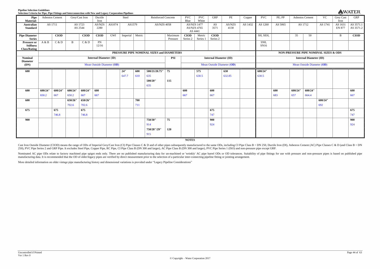
Pipeline Selection Guidelines
Selection Criteria for Pipe, Pipe Fittings and Interconnection with New and Legacy Corporation Pipelines
Uncontrolled if Printed Page 44 of 63 Ver 1 Rev 0
© Copyright – Water Corporation 2017
Pipe
Material:
Asbestos Cement Grey/Cast Iron Ductile
Iron
Steel Reinforced Concrete PVC
Blue
PVC
White
GRP PE Copper PVC PE; PP Asbestos Cement VC Grey Cast
Iron
GRP
Australian
Standard
AS 1711 AS 1723
AS 2544
AS/NZS
2280
AS1074 AS1579 AS/NZS 4058 AS/NZS 1477
AS/NZS 4765
AS 4441
AS
3571
AS/NZS
4130
AS 1432 AS 1260 AS 5065 AS 1712 AS 1741 AS 1631
EN 877
AS 3571.1
AS 3571.2
Pipe Diameter
Series
CIOD CIOD CIOD GWI Imperial Metric Maximum
Pressure CIOD
Series 2
Metric
Series 1 CIOD
Series 2
SH, SEH, 35 50 B CIOD
Pressure or
Stiffness
Class/Rating
A & B C & D B C & D PN
12/16
SN8,
SN16
PRESSURE PIPE NOMINAL SIZES and DIAMETERS NON-PRESSURE PIPE NOMINAL SIZES & ODS
Nominal
Diameter
Internal Diameter (ID) PSI Internal Diameter (ID) Internal Diameter (ID)
(DN) Mean Outside Diameter (OD) Mean Outside Diameter (OD) Mean Outside Diameter (OD)
600 24" 600 500/21/20.75" 75 575 630 600/24"
647.7 610 635 630.5 632.85 630.5
500/20" 115
635
600 600/24" 600/24" 600/24" 600/24" 600 600 600 600 600/24" 600/24" 600
650.2 667 650.2 667 667 667 667 683 657 664.4 667
600 650/26" 650/26" 700 600/24"
702.6 702.6 711 692
675 675 675 675 675
746.8 746.8 747 747
900 750/30" 75 900 900
914 924 924
750/28"/29" 120
915
NOTES
Cast Iron Outside Diameter (CIOD) means the range of ODs of Imperial Grey/Cast Iron (CI) Pipe Classes C & D and of other pipes subsequently manufactured to the same ODs, including CI Pipe Class B < DN 250, Ductile Iron (DI), Asbestos Cement (AC) Pipe Classes C & D (and Class B < DN
250), PVC Pipe Series 2 and GRP Pipe. It excludes Steel Pipe, Copper Pipe, RC Pipe, CI Pipe Class B (DN 300 and larger), AC Pipe Class B (DN 300 and larger), PVC Pipe Series 1 (ISO) and non-pressure pipe except GRP.
Nominated AC pipe ODs relate to factory machined pipe spigot ends only. There are no published manufacturing data for un-machined or 'wrinkly' AC pipe barrel ODs or OD tolerances. Suitability of pipe fittings for use with pressure and non-pressure pipes is based on published pipe
manufacturing data. It is recommended that the OD of older/legacy pipes are verified by direct measurement prior to the selection of a particular inter-connecting pipeline fitting or jointing arrangement.
More detailed information on older vintage pipe manufacturing history and dimensional variations is provided under “Legacy Pipeline Considerations”
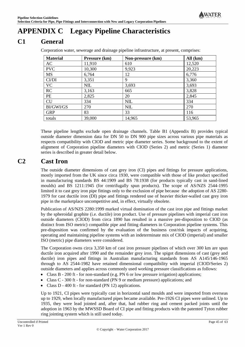
Pipeline Selection Guidelines
Selection Criteria for Pipe, Pipe Fittings and Interconnection with New and Legacy Corporation Pipelines
Uncontrolled if Printed Page 45 of 63 Ver 1 Rev 0
© Copyright – Water Corporation 2017
APPENDIX C Legacy Pipeline Characteristics
C1 General
Corporation water, sewerage and drainage pipeline infrastructure, at present, comprises:
Material Pressure (km) Non-pressure (km) All (km)
AC 11,910 610 12,520
PVC 10,300 9,923 20,223
MS 6,764 12 6,776
CI/DI 3,351 9 3,360
VC NIL 3,693 3,693
RC 3,163 665 3,828
PE 2,825 20 2,845
CU 334 NIL 334
BI/GWI/GS 270 NIL 270
GRP 83 33 116
totals 39,000 14,965 53,965
These pipeline lengths exclude open drainage channels. Table B1 (Appendix B) provides typical
outside diameter dimension data for DN 50 to DN 900 pipe sizes across various pipe materials as
respects compatibility with CIOD and metric pipe diameter series. Some background to the extent of
alignment of Corporation pipeline diameters with CIOD (Series 2) and metric (Series 1) diameter
series is described in greater detail below.
C2 Cast Iron
The outside diameter dimensions of cast grey iron (CI) pipes and fittings for pressure applications,
mostly imported from the UK since circa 1930, were compatible with those of like product specified
in manufacturing standards BS 44:1909 and BS 78:1938 (for products typically cast in sand-lined
moulds) and BS 1211:1945 (for centrifugally spun products). The scope of AS/NZS 2544-1995
limited it to cast grey iron pipe fittings only to the exclusion of pipe because the adoption of AS 2280-
1979 for cast ductile iron (DI) pipe and fittings rendered use of heavier thicker-walled cast grey iron
pipe in the marketplace uncompetitive and, in effect, virtually obsolete.
Publication of AS/NZS 2280:1999 marked virtual domination of the cast iron pipe and fittings market
by the spheroidal graphite (i.e. ductile) iron product. Use of pressure pipelines with imperial cast iron
outside diameters (CIOD) from circa 1890 has resulted in a massive pre-disposition to CIOD (as
distinct from ISO metric) compatible pipe and fitting diameters in Corporation pipeline systems. This
pre-disposition was confirmed by the evaluation of the business cost/risk impacts of acquiring,
operating and maintaining pipeline systems with an indeterminate mix of CIOD (imperial) and smaller
ISO (metric) pipe diameters were considered.
The Corporation owns circa 3,350 km of cast iron pressure pipelines of which over 300 km are spun
ductile iron acquired after 1990 and the remainder grey iron. The spigot dimensions of cast (grey and
ductile) iron pipes and fittings in Australian manufacturing standards from AS A145/146-1965
through to AS 2544-1982 have retained dimensional compatibility with imperial (CIOD/Series 2)
outside diameters and applies across commonly used working pressure classifications as follows:
Class B - 200 ft - for non-standard (e.g. PN 6 or low pressure irrigation) applications;
Class C - 300 ft - for non-standard (PN 9 or medium pressure) applications; and
Class D - 400 ft - for standard (PN 12) applications.
Up to 1921, CI pipes were typically cast in horizontal sand moulds and were imported from overseas
up to 1929, when locally manufactured pipes became available. Pre-1926 CI pipes were unlined. Up to
1935, they were lead jointed and, after that, had rubber ring and cement packed joints until the
adoption in 1963 by the MWSSD Board of CI pipe and fitting products with the patented Tyton rubber
ring jointing system which is still used today.
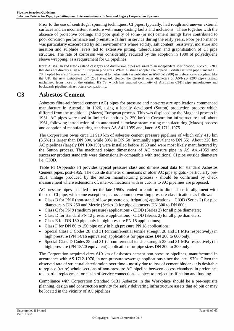
Pipeline Selection Guidelines
Selection Criteria for Pipe, Pipe Fittings and Interconnection with New and Legacy Corporation Pipelines
Uncontrolled if Printed Page 46 of 63 Ver 1 Rev 0
© Copyright – Water Corporation 2017
Prior to the use of centrifugal spinning techniques, CI pipes, typically, had rough and uneven external
surfaces and an inconsistent structure with many casting faults and inclusions. These together with the
absence of protective coatings and poor quality of some (or no) cement linings have contributed to
poor corrosion performance and premature failure in service during the early years. Poor performance
was particularly exacerbated by soil environments where acidity, salt content, resistivity, moisture and
aeration and sulphide levels led to extensive pitting, tuberculation and graphitisation of CI pipe
structure. The rate of corrosion was considerably reduced by the adoption in 1980 of polyethylene
sleeve wrapping, as a requirement for CI pipelines.
Note: Australian and New Zealand cast grey and ductile iron pipes are sized to an independent specification, AS/NZS 2280,
that does not directly align with European pipe sizes. While Australia adopted the imperial British cast iron pipe standard BS
78, it opted for a 'soft' conversion from imperial to metric units (as published in AS/NSZ 2280) in preference to adopting, like
the UK, the new metricated ISO 2531 standard. Hence, the physical outer diameters of AS/NZS 2280 pipes remain
unchanged from those of the original BS 78, which has enabled continuity of Australian CI/DI pipe manufacture and
backwards pipeline infrastructure compatibility.
C3 Asbestos Cement
Asbestos fibre-reinforced cement (AC) pipes for pressure and non-pressure applications commenced
manufacture in Australia in 1926, using a locally developed (Sutton) production process which
differed from the traditional (Mazza) European process. This was displaced by the Magnani process in
1951. AC pipes were used in limited quantities (< 250 km) in Corporation infrastructure until about
1961, following introduction of an automated autoclave steam curing manufacturing (Mazza) process
and adoption of manufacturing standards AS A41-1959 and, later, AS 1711-1975.
The Corporation owns circa 11,910 km of asbestos cement pressure pipelines of which only 415 km
(3.5%) is larger than DN 300, while 30% is DN 58 (nominally equivalent to DN 65). About 220 km
AC pipelines (largely DN 100/150) were installed before 1950 and were most likely manufactured by
the Sutton process. The machined spigot dimensions of AC pressure pipe in AS A41-1959 and
successor product standards were dimensionally compatible with traditional CI pipe outside diameters
i.e. CIOD.
Table F1 (Appendix F) provides typical pressure class and dimensional data for standard Asbestos
Cement pipes, post-1959. The outside diameter dimensions of older AC pipe spigots - particularly pre-
1951 vintage produced by the Sutton manufacturing process - should be confirmed by check
measurement where extensions of, inter-connections with or cut-ins to AC pipelines are proposed.
AC pressure pipes installed after the late 1950s tended to conform to dimensions in alignment with
those of CI pipe, with some exceptions, across common working pressure classifications as follows:
Class B for PN 6 (non-standard low pressure e.g. irrigation) applications – CIOD (Series 2) for pipe
diameters < DN 250 and Metric (Series 1) for pipe diameters DN 300 to DN 600;
Class C for PN 9 (medium pressure) applications - CIOD (Series 2) for all pipe diameters;
Class D for standard PN 12 pressure applications - CIOD (Series 2) for all pipe diameters;
Class E for DN 150 pipe only in high pressure PN 15 applications;
Class F for DN 80 to 150 pipe only in high pressure PN 18 applications;
Special Class C Codes 28 and 31 (circumferential tensile strength 28 and 31 MPa respectively) in
high pressure (PN 14/16 equivalent) applications for pipe sizes DN 200 to 600 only;
Special Class D Codes 28 and 31 (circumferential tensile strength 28 and 31 MPa respectively) in
high pressure (PN 18/20 equivalent) applications for pipe sizes DN 200 to 300 only.
The Corporation acquired circa 610 km of asbestos cement non-pressure pipelines, manufactured in
accordance with AS 1712-1976, in non-pressure sewerage applications since the late 1970s. Given the
observed rate of structural deterioration over time - mostly due to loss of cement binder - it is desirable
to replace (retire) whole sections of non-pressure AC pipeline between access chambers in preference
to a partial replacement or cut-in of service connections, subject to project justification and funding.
Compliance with Corporation Standard S131 Asbestos in the Workplace should be a pre-requisite
planning, design and construction activity for safely delivering infrastructure assets that adjoin or may
be located in the vicinity of AC pipelines.
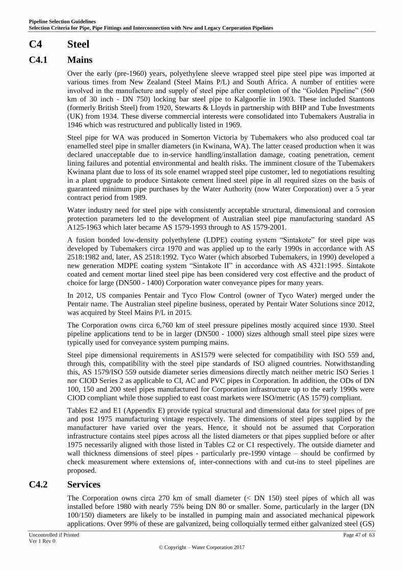
Pipeline Selection Guidelines
Selection Criteria for Pipe, Pipe Fittings and Interconnection with New and Legacy Corporation Pipelines
Uncontrolled if Printed Page 47 of 63 Ver 1 Rev 0
© Copyright – Water Corporation 2017
C4 Steel
C4.1 Mains
Over the early (pre-1960) years, polyethylene sleeve wrapped steel pipe steel pipe was imported at
various times from New Zealand (Steel Mains P/L) and South Africa. A number of entities were
involved in the manufacture and supply of steel pipe after completion of the “Golden Pipeline” (560
km of 30 inch - DN 750) locking bar steel pipe to Kalgoorlie in 1903. These included Stantons
(formerly British Steel) from 1920, Stewarts & Lloyds in partnership with BHP and Tube Investments
(UK) from 1934. These diverse commercial interests were consolidated into Tubemakers Australia in
1946 which was restructured and publically listed in 1969.
Steel pipe for WA was produced in Somerton Victoria by Tubemakers who also produced coal tar
enamelled steel pipe in smaller diameters (in Kwinana, WA). The latter ceased production when it was
declared unacceptable due to in-service handling/installation damage, coating penetration, cement
lining failures and potential environmental and health risks. The imminent closure of the Tubemakers
Kwinana plant due to loss of its sole enamel wrapped steel pipe customer, led to negotiations resulting
in a plant upgrade to produce Sintakote cement lined steel pipe in all required sizes on the basis of
guaranteed minimum pipe purchases by the Water Authority (now Water Corporation) over a 5 year
contract period from 1989.
Water industry need for steel pipe with consistently acceptable structural, dimensional and corrosion
protection parameters led to the development of Australian steel pipe manufacturing standard AS
A125-1963 which later became AS 1579-1993 through to AS 1579-2001.
A fusion bonded low-density polyethylene (LDPE) coating system “Sintakote” for steel pipe was
developed by Tubemakers circa 1970 and was applied up to the early 1990s in accordance with AS
2518:1982 and, later, AS 2518:1992. Tyco Water (which absorbed Tubemakers, in 1990) developed a
new generation MDPE coating system “Sintakote II” in accordance with AS 4321:1995. Sintakote
coated and cement mortar lined steel pipe has been considered very cost effective and the product of
choice for large (DN500 - 1400) Corporation water conveyance pipes for many years.
In 2012, US companies Pentair and Tyco Flow Control (owner of Tyco Water) merged under the
Pentair name. The Australian steel pipeline business, operated by Pentair Water Solutions since 2012,
was acquired by Steel Mains P/L in 2015.
The Corporation owns circa 6,760 km of steel pressure pipelines mostly acquired since 1930. Steel
pipeline applications tend to be in larger (DN500 - 1000) sizes although small steel pipe sizes were
typically used for conveyance system pumping mains.
Steel pipe dimensional requirements in AS1579 were selected for compatibility with ISO 559 and,
through this, compatibility with the steel pipe standards of ISO aligned countries. Notwithstanding
this, AS 1579/ISO 559 outside diameter series dimensions directly match neither metric ISO Series 1
nor CIOD Series 2 as applicable to CI, AC and PVC pipes in Corporation. In addition, the ODs of DN
100, 150 and 200 steel pipes manufactured for Corporation infrastructure up to the early 1990s were
CIOD compliant while those supplied to east coast markets were ISO/metric (AS 1579) compliant.
Tables E2 and E1 (Appendix E) provide typical structural and dimensional data for steel pipes of pre
and post 1975 manufacturing vintage respectively. The dimensions of steel pipes supplied by the
manufacturer have varied over the years. Hence, it should not be assumed that Corporation
infrastructure contains steel pipes across all the listed diameters or that pipes supplied before or after
1975 necessarily aligned with those listed in Tables C2 or C1 respectively. The outside diameter and
wall thickness dimensions of steel pipes - particularly pre-1990 vintage – should be confirmed by
check measurement where extensions of, inter-connections with and cut-ins to steel pipelines are
proposed.
C4.2 Services
The Corporation owns circa 270 km of small diameter (< DN 150) steel pipes of which all was
installed before 1980 with nearly 75% being DN 80 or smaller. Some, particularly in the larger (DN
100/150) diameters are likely to be installed in pumping main and associated mechanical pipework
applications. Over 99% of these are galvanized, being colloquially termed either galvanized steel (GS)

Pipeline Selection Guidelines
Selection Criteria for Pipe, Pipe Fittings and Interconnection with New and Legacy Corporation Pipelines
Uncontrolled if Printed Page 48 of 63 Ver 1 Rev 0
© Copyright – Water Corporation 2017
or galvanized wrought iron (GWI). Steel tubes (pipes) DN 150 and smaller in diameter were produced
in accordance with manufacturing standards AS B105:1951 through to AS 1074:1989 and were
originally in close alignment with BS 1387:1957.
The use of copper pipe (330 km from 1960 to 1990) and plastics from the late 1980s onward obviated
the demand for small diameter steel pipe and replaced considerable sections of steel pipe/tube that had
reached the end of their useful life. Copper pipelines were produced in accordance with copper tube
manufacturing standards AS B2:1928 through to AS 1432:2004. There were no formal documented
national standards for metallic (copper) pipe fittings nor for the installation and commissioning of
copper pipe and fittings until the publication of AS 3688:1994 and 4809:2003 respectively.
C4.3 Stainless Steel
The lengths of stainless steel tubing incorporated in process pipeline networks (e.g. treatment plants)
and – as pipework specials - in larger conveyance systems has not been specifically recorded by
Corporation GIS systems. Stainless steel (SS) tube/pipe is typically produced in accordance with
manufacturing standard ASTM A269 or ASTM A312 for general service - low temperature, non-
corrosive and schedule piping for high temperature applications respectively, using austenitic SS
material. Pipe for high temperature and corrosive fluid applications is usually ferritic or austenitic
(duplex or super-duplex) SS material e.g. ASTM A790, A789 or A928 as appropriate to the particular
fluid, chemical process, temperature and pressure applications.
C5 Concrete
The Corporation owns circa 3,170 km of RC pressure pipelines and 710 km of non-pressure RC
pipelines in DN375 to 2250 sizes. 90% of RC pressure pipelines are smaller than DN 225 and 99% of
all RC pipelines were acquired since 1950.
Tables D1 and D2 (Appendix D) provide typical structural and dimensional data for legacy RC
pressure pipe used for water conveyance up to the 1980s and beyond.
Non-pressure RC pipe dimensions have generally been as nominated by the pipe manufacturer (e.g.
Humes and Rocla) with ID values approximating nominal diameters (or DN) as nominated in the RC
pipe manufacturing standard AS/NZS 4058. The outside diameters of RC pressure pipes did not
generally conform to recognized (e.g. CIOD, ISO) water industry dimensions which existed from the
turn of the century. Given the extent and uncertainty of OD variation across the (buried) RC pressure
pipe legacy ‘population’, these should be confirmed by check measurement prior to detailing any
extension of, inter-connection with and cut-in to an RC pressure pipeline and prior to selecting pipe
fittings and associated inter-connectors or couplings.
C6 Vitrified Clay
The Corporation owns circa 3,690 km of vitrified (or vitreous) clay (VC) non-pressure pipelines in DN
100 to 450 sizes of which over 80% are in the DN 100 to 150 size range. VC pipelines were typically
used for ‘gravity’ sewerage applications from the 1920s with over 63% being installed between 1960
and 1990. Production of VC pipes for pressure applications did not prove commercially viable.
VC pipe dimensions generally conformed with VC pipe manufacturing standards from AS B57-1935
through to AS 1741-1991. VC pipe and fitting joints were traditionally rigid – typically cement mortar
packed – until the introduction of a 4” (DN 100) rubber ring joint design in AS A165-1968 to
accompany AS A164-1968 for pipe with both rigid and flexible joint sockets. Publication in 1975 of
manufacturing standard AS 1741, provided for flexible (or rubber ring) VC pipe and fitting joints
across all manufactured diameters. VC pipes are known to have been imported from the UK over the
years but little is known about when and where installed.
The outside diameters of VC pipes spigots do not directly align with those of other commonly used
non-pressure or pressure pipe materials. Imported VC pipe dimensions - typically manufactured to UK
standards – also differed from Australian Standard VC pipe dimensions. In the unlikely event that a
VC pipe spigot is to be directly connected to a pipe spigot of another pipe material, both ODs should
be verified prior to selecting inter-connection couplings.

Pipeline Selection Guidelines
Selection Criteria for Pipe, Pipe Fittings and Interconnection with New and Legacy Corporation Pipelines
Uncontrolled if Printed Page 49 of 63 Ver 1 Rev 0
© Copyright – Water Corporation 2017
Given the performance history of VC pipeline joint integrity including resistance to root intrusion, the
replacement of whole - in preference to partial - VC pipeline sections should be considered, subject to
project requirements justification and funding.
C7 Plastics
C7.1 Polyethylene
First generation PE pipe materials – low and high density polyethylene (LDPE & HDPE) – date back
to the early 1930s and 1950s respectively. Manufacturing standards AS K119-1962 through to AS
1159-1973, 1979 and 1988 classified pressure pipe made from these PE materials as Type 30 - LDPE
with a tensile strength of 3 MPa - and Type 50 - HDPE with a tensile strength of 5 MPa - respectively.
PE pressure pipe manufactured with second generation PE polymers – medium density polyethylene
(MDPE) – became available and was to dominate the PE pipe market in the late 1980s.
Minimum performance requirements for polyethylene (PE) compounds for Australian PE pressure
pipes and fittings were formally published in AS K125-1963, based on UK requirements in BS
1973:1953. These requirements were substantially upgraded in AS/NZS 4131:2001 and, later, in
AS/NZS4131:2003 to reflect the modern PE compounds market.
The availability of third generation polymers PE 80B (‘MDPE’) - with an 8 MPa tensile strength - and
PE 100 (‘HDPE’) with a 10 MPa tensile strength - led to the publication of AS/NZS 4130:2003 for PE
pressure pipe. The higher tensile strength, better resistance to slow crack growth and material
efficiency of PE 100 has resulted in its current dominance of the PE pressure pipe market.
Australian manufacturing and performance requirements for PE pressure pipe fittings were first
published in AS 1460-1973, followed by AS 1460-1989 and, in 1997, AS/NZS 4129 (Int). The latter
evolved into AS/NZS 4129:2000 which was modernized to AS/NZS 4129:2008.
The first documented national standard for installing PE pipelines, AS 2033, was published in 1977.
This was substantially revised and upgraded as AS/NZS 2033 in 2008. AS/NZS 2033 is the currently
accepted basis for installing PE pipe systems across the water industry nationally.
The Corporation owns circa 2,840 km of polyethylene (PE) pipelines of which 20 km represent non-
pressure pipelines including a (failed & decommissioned) cohort of ribbed profile PE sewers. PE
pressure pipes were installed mostly from 1980 onwards with nearly 90% being DN 100 or smaller.
Nearly 50% of PE pipelines are DN 63, the predominant size/material combination in urban cul-de-sac
service applications in preference to the older traditional DN 50 copper service pipe.
C7.2 PVC
Australian manufacturing and performance requirements for Unplasticised Polyvinyl Chloride (uPVC)
pressure and non-pressure pipes and fittings (with metric/ISO diameters) were first published in AS
K138-1963 and AS A159-1969 respectively. This was progressively revised between 1988 and 1990
and re-designated AS 1477, Parts 1 to 6 – 1973. Parts 1, 2, 4 & 6 were scoped for pressure applications
only. A new manufacturing standard AS 2977, Parts 1 to 3 (pipes, fittings and joints) was introduced
to cater for PVC pipe diameters with CIOD dimensions, given the dominance of cast iron pipe
diameters in legacy pipeline systems. AS/NZS 1477:1996 replaced the separate need for AS 1477 and
AS 2977 by designating Series 1 and Series 2 diameters for equivalence with metric/ISO and CIOD
dimensions respectively, whilst incorporating performance requirements for both in common. The
current PVC-U (uPVC) pressure pipe and fittings manufacturing standard is AS/NZS 1477:2006.
Instances of premature failure of uPVC pressure pipes - many related to impact resistance performance
and overall material sustainability of this relatively thick-walled product - resulted in the introduction
of modified PVC (PVC-M) pressure pipes and publication of a manufacturing standard AS/NZS 4765
(Int):2000. PVC-M pipes were thinner walled and exhibited more predictable rupture characteristics
by virtue of added impact modifiers. On the other hand, the higher ductility of PVC-M pipe material
and its consequently ‘poorer’ cyclic fatigue performance has limited its use to lower pumping
frequency applications, as compared with other plastics - including PVC-U and PVC-O pipe materials.
Although molecular-oriented PVC (PVC-O) pipe was introduced in Australia in the 1980s, its
competitive production was enabled only by comparatively recent advancements in PVC-O pipe

Pipeline Selection Guidelines
Selection Criteria for Pipe, Pipe Fittings and Interconnection with New and Legacy Corporation Pipelines
Uncontrolled if Printed Page 50 of 63 Ver 1 Rev 0
© Copyright – Water Corporation 2017
manufacturing technology. The early manufacturing standard for PVC-O pressure pipe AS/NZS 4441
(Int):1996 evolved into the current standard AS/NZS 4441:2008.
The limited resistance of PVC - particularly PVC-M and, to a lesser extent, PVC-U - pressure
pipelines to frequent cyclic pressure fluctuations – usually generated by pump and valve operations –
is unlikely to have been considered or quantified in the past by designers. The cyclic fatigue
characteristics and longevity of legacy PVC pipelines should accordingly be evaluated as a pre-
requisite of new pipeline system designs that incorporate legacy PVC pipe into new pipeline systems.
The Corporation owns circa 10,400 km of PVC pressure pipelines and 9,920 km of PVC non-pressure
(sewerage and drainage) pipelines. Virtually all were installed from the late 1980s onwards. 94% of
PVC pressure pipelines and 99% of PVC non-pressure pipelines are DN 300 or smaller.
C7.3 GRP
Manufacturing and performance requirements for Glass Reinforced thermo-Plastics (GRP) pipe
systems (with CIOD compatible diameters) were first published in AS 3571-1989. These formally
confirmed Australian performance requirements for centrifugally cast GRP pipes, produced under
licence from the (Swedish/Swiss) proprietors of the HOBAS GRP pipe system manufacturing process.
The manufacture of cast GRP pipes systems (HOBAS) ceased in Australia circa 2006, following the
establishment in Australia of a filament wound (Flowtite) GRP pipe manufacturing process. AS
3571.1:2009 and AS 3571.2:2009 were developed by Australian GRP pipe system users by adopting
GRP pipe system standards ISO 10467 and ISO 10639 respectively for drainage/sewerage and water
supply applications. An Australia-specific Appendix ZZ in both parts of AS 3571 includes provision
for CIOD compliant pipe diameters (Table 5) for Australian water industry applications.
The Corporation owns circa 83 km of GRP pressure pipelines and 33 km of GRP non-pressure
(sewerage and drainage) pipelines. Virtually all were installed from the early 1980s onwards. 96% of
GRP pressure pipelines and all GRP non-pressure pipelines are DN 375 or larger.

Pipeline Selection Guidelines
Selection Criteria for Pipe, Pipe Fittings and Interconnection with New and Legacy Corporation Pipelines
Uncontrolled if Printed Page 51 of 63 Ver 1 Rev 0
© Copyright – Water Corporation 2017
APPENDIX D
Table D1 Steel Pipes - Dimensions (Vintage 1975 to Current)
Dimensions
MAOP
Minimum
Yield
Strength
Paper
Record
Date DN O.D. Steel Plate
Thickness
I.D.
(Lined)
Cement
Mortar
Lining
Thickness
mm mm mm mm mm m MPa
100 114.00 4.80 86.00 9.00 >350 300 Nov-08
100 114.00 5.00 92.00 6.00 >300 Jan-78
100 120.65 92.08 9.53
Nov-75
100 121.00 5.00 95.00 8.00 >300 Apr-90
100 121.00 5.00 91.00 8.00 >300 1989
150 168.00 5.00 140.00 9.00 >350 300 Nov-08
150 178.00 5.00 152.00 8.00 >300 Apr-90
150 168.00 5.00 146.00 6.00 >300 Jan-78
150 177.80 4.76 149.23 9.53 Nov-75
150 178.00 5.00 148.00 8.00 >300 1989
200 219.00 5.00 191.00 9.00 >350 300 Nov-08
200 235.00 5.00 209.00 8.00 >300 Apr-90
200 219.00 5.00 197.00 6.00 >300 Jan-78
205 234.95 4.76 206.38 9.53 Nov-75
200 235.00 5.00 148 8 >300 1989
250 273.00 5.00 245.00 9.00 >350 300 Nov-08
250 273.00 5.00 243.00 10.00 >300 Jan-78
255 292.10 4.76 263.53 9.53 Nov-75
300 324.00 5.00 290.00 12.00 >350 300 Nov-08
300 324.00 5.00 294.00 10.00 >300 Apr-90
305 349.25 4.76 320.68 9.53 Nov-75
300 324.00 5.00 294.00 10.00 >300 1989
350 356.00 5.00 326.00 10.00 >300 Jan-78
380 425.45 4.76 390.53 12.70 Nov-75
400 406.00 5.00 372.00 12.00 >350 300 Nov-08
400 406.00 5.00 376.00 10.00 >300 1989
400 406.00 5.00 376.00 10.00 >300 Jan-78
450 457.00 5.00 427.00 10.00 >300 Jan-78
460 488.95 4.75 454.03 12.70 Nov-75
460 498.48 6.35 460.38 12.70 Nov-75

Pipeline Selection Guidelines
Selection Criteria for Pipe, Pipe Fittings and Interconnection with New and Legacy Corporation Pipelines
Uncontrolled if Printed Page 52 of 63 Ver 1 Rev 0
© Copyright – Water Corporation 2017
Dimensions
MAOP
Minimum
Yield
Strength
Paper
Record
Date DN O.D. Steel Plate
Thickness
I.D.
(Lined)
Cement
Mortar
Lining
Thickness
mm mm mm mm mm m MPa
500 508.00 5.00 474.00 12.00 >350 300 Nov-08
500 508.00 5.00 478.00 10.00 285 Jan-78
500 508.00 5.00 478.00 10.00 285 1989
535 568.33 4.76 533.40 12.70 Nov-75
535 571.50 6.35 533.40 12.70 Nov-75
535 577.85 9.53 533.40 12.70 Nov-75
600 610.00 6.00 574.00 12.00 >350 300 Nov-08
600 610.00 5.00 576.00 12.00 180 Jan-78
610 647.70 6.35 609.60 12.70
Nov-75
600 610.00 6.00 574.00 12.00 295 1989
700 711.00 6.00 675.00 12.00 >350 300 Nov-08
700 711.00 6.00 675.00 12.00 210 Apr-90
700 711.00 6.00 675.00 12.00 >350
700 711.00 7.00 673.00 12.00 300 Jan-78
700 711.00 6.00 675.00 12.00 210 1989
760 800.10 6.35 762.00 12.70 Nov-75
760 803.28 7.94 762.00 12.70 Nov-75
800 813.00 7.00 767.00 16.00 >350 300 Nov-08
800 813.00 6.00 769.00 16.00
Jan-78
800 813.00 7.00 767.00 16.00 225 Jan-78
800 813.00 8.00 765.00 16.00 300 Jan-78
800 813.00 7.00 767.00 16.00 225 1989
900 914.00 7.00 868.00 16.00 337 300 Nov-08
900 914.00 7.00 868.00 16.00 160 Apr-90
900 914.00 8.00 866.00 16.00 235 Apr-90
900 914.00 7.00 868.00 16.00 337 1989
900 914.00 7.00 868.00 16.00 160 Jan-78
900 914.00 8.00 866.00 16.00 235 Jan-78
900 914.00 9.00 864.00 16.00 300 Jan-78
900 914.00 7.00 868.00 16.00 160 1989
900 914.00 8.00 866.00 16.00 235 1989
915 965.20 9.53 914.40 15.88
Nov-75
1000 1016.00 8.00 968.00 16.00 300 Nov-08

Pipeline Selection Guidelines
Selection Criteria for Pipe, Pipe Fittings and Interconnection with New and Legacy Corporation Pipelines
Uncontrolled if Printed Page 53 of 63 Ver 1 Rev 0
© Copyright – Water Corporation 2017
Dimensions
MAOP
Minimum
Yield
Strength
Paper
Record
Date DN O.D. Steel Plate
Thickness
I.D.
(Lined)
Cement
Mortar
Lining
Thickness
mm mm mm mm mm m MPa
1000 1016.00 8.00 968.00 16.00 180 Apr-90
1000 1016.00 9.00 966.00 16.00 250 Apr-90
1000 1016.00 10.00 964.00 16.00 305 Jan-78
1000 1016.00 8.00 968.00 16.00 347
1000 1016.00 8.00 968.00 16.00 180 1989
1000 1016.00 9.00 966.00 16.00 250 1989
1065 1123.95 9.53 1066.80 19.05 Nov-78
1065 1127.12 11.11 1066.80 19.05 Nov-78
1200 1219.00 9.00 1169.00 16.00 271 Nov-08
1200 1220.00 9.00 1162.00 20.00 140 Apr-90
1200 1220.00 10.00 1160.00 20.00 210 Apr-90
1200 1219.00 9.00 1164.00 19.00 271
1200 1220.00 11.00 1158.00 20.00 255 Jan-78
1200 1220.00 12.00 1156.00 20.00 300 Jan-78
1220 1279.53 11.11 1219.20 19.05 Nov-75
1200 1220.00 9.00 1162.00 20.00 140 1989
1200 1220.00 10.00 1160.00 20.00 210 1989
1370 1428.75 9.53 1371.60 19.05 Nov-75
1370 1431.92 11.11 1371.60 19.05 Nov-75
1370 1433.50 11.91 1371.60 19.05 Nov-75
1370 1435.10 12.70 1371.60 19.05 Nov-75
1370 1436.69 13.50 1371.60 19.05 Nov-75
1370 1441.45 15.88 1371.60 19.05 Nov-75
1400 1422.00 11.00 1360.00 19.00 284 250 Nov-08
1400 1422.00 11.00 1360.00 19.00 340 300 Nov-08
1400 1420.00 11.00 1358.00 20.00 170 Jan-78
1400 1420.00 12.00 1356.00 20.00 220 Jan-78
1400 1420.00 13.00 1354.00 20.00 260 Jan-78
1400 1420.00 14.00 1352.00 20.00 300 Jan-78
1400 1420.00 12.00 1358.00 20.00 220 Apr-90
1400 1422.00 11.00 1360.00 19.00 284
1400 1420.00 11.00 1358.00 20.00 170 1989
1400 1420.00 12.00 1358.00 20.00 220 1989

Pipeline Selection Guidelines
Selection Criteria for Pipe, Pipe Fittings and Interconnection with New and Legacy Corporation Pipelines
Uncontrolled if Printed Page 54 of 63 Ver 1 Rev 0
© Copyright – Water Corporation 2017
Dimensions
MAOP
Minimum
Yield
Strength
Paper
Record
Date DN O.D. Steel Plate
Thickness
I.D.
(Lined)
Cement
Mortar
Lining
Thickness
mm mm mm mm mm m MPa
1400 1420.00 13.00 1354.00 20.00 260 1989
1520 1587.50 12.70 1524.00 19.05
Nov-75
1600 1620.00 12.00 1546.00 25.00 135 Jan-78
1600 1620.00 13.00 1544.00 25.00 185 Jan-78
1600 1620.00 14.00 1542.00 25.00 225 Jan-78
1600 1620.00 15.00 1540.00 25.00 260 Jan-78
1600 1620.00 16.00 1538.00 25.00 295 Jan-78
1600 1620.00 12.00 1546.00 25.00 135 1989
1600 1620.00 13.00 1544.00 25.00 185 1989
1600 1620.00 14.00 1542.00 25.00 225 1989
1600 1620.00 15.00 1540.00 25.00 260 1989
1675 1701.80 12.70 1676.40 0.00 Nov-75
1800 1872.00 16.00 1838.00 25.00 Apr-90
1830 1905.00 19.05 1828.80 19.05 Nov-75
1800 1872.00 16.00 1838.00 25.00 1989
1920 2057.40 19.05 1981.20 19.05 Nov-75
2090 2108.20 10.32 2087.56 0.00 Nov-75
Note 1: All data and data gaps shown have been transcribed from known historical paper records.
Note 2: Pipes were low density polyethylene (LDPE) coated prior to 1990 and, after this, medium density
polyethylene (MDPE). PE coating thickness ranged from 1.6 mm for DN < 250 to 3 mm for DN > 900.
Note 3: Cement mortar lining thickness tolerances ranged from + 3 mm for DN < 300 to + 4 mm for DN > 300.
Assumptions Standards
Density of steel 7850 kg.m
3
AS1579 - Arc Welding Steel Pipes
Density of concrete 2400kg/m
3
AS1281 - Cement Mortar Lining of Steel Pipes
Mass of Coating 925 kg/m
3
AS 4321 - Fusion Bonded medium Density PE
Coating
Pipe lengths
Standard length of all pipes = 12.3m (12m nominal) or 9m nominal
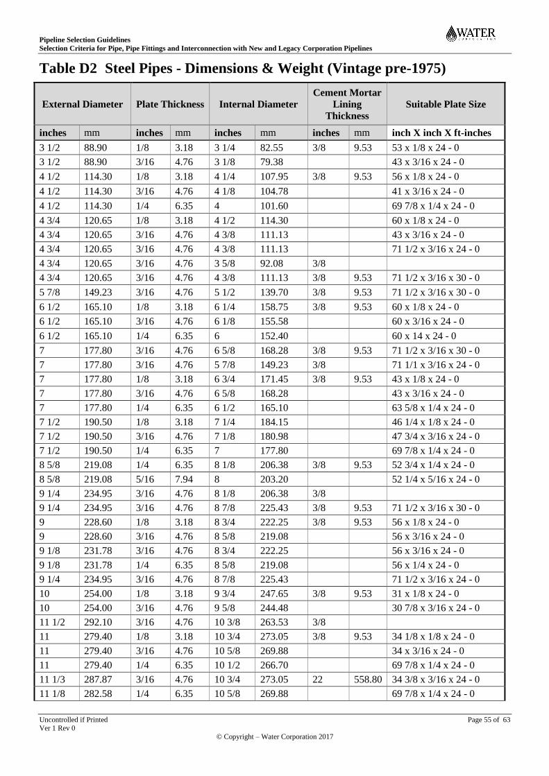
Pipeline Selection Guidelines
Selection Criteria for Pipe, Pipe Fittings and Interconnection with New and Legacy Corporation Pipelines
Uncontrolled if Printed Page 55 of 63 Ver 1 Rev 0
© Copyright – Water Corporation 2017
Table D2 Steel Pipes - Dimensions & Weight (Vintage pre-1975)
External Diameter Plate Thickness Internal Diameter
Cement Mortar
Lining
Thickness
Suitable Plate Size
inches mm inches mm inches mm inches mm inch X inch X ft-inches
3 1/2 88.90 1/8 3.18 3 1/4 82.55 3/8 9.53 53 x 1/8 x 24 - 0
3 1/2 88.90 3/16 4.76 3 1/8 79.38
43 x 3/16 x 24 - 0
4 1/2 114.30 1/8 3.18 4 1/4 107.95 3/8 9.53 56 x 1/8 x 24 - 0
4 1/2 114.30 3/16 4.76 4 1/8 104.78
41 x 3/16 x 24 - 0
4 1/2 114.30 1/4 6.35 4 101.60
69 7/8 x 1/4 x 24 - 0
4 3/4 120.65 1/8 3.18 4 1/2 114.30
60 x 1/8 x 24 - 0
4 3/4 120.65 3/16 4.76 4 3/8 111.13
43 x 3/16 x 24 - 0
4 3/4 120.65 3/16 4.76 4 3/8 111.13
71 1/2 x 3/16 x 24 - 0
4 3/4 120.65 3/16 4.76 3 5/8 92.08 3/8
4 3/4 120.65 3/16 4.76 4 3/8 111.13 3/8 9.53 71 1/2 x 3/16 x 30 - 0
5 7/8 149.23 3/16 4.76 5 1/2 139.70 3/8 9.53 71 1/2 x 3/16 x 30 - 0
6 1/2 165.10 1/8 3.18 6 1/4 158.75 3/8 9.53 60 x 1/8 x 24 - 0
6 1/2 165.10 3/16 4.76 6 1/8 155.58
60 x 3/16 x 24 - 0
6 1/2 165.10 1/4 6.35 6 152.40
60 x 14 x 24 - 0
7 177.80 3/16 4.76 6 5/8 168.28 3/8 9.53 71 1/2 x 3/16 x 30 - 0
7 177.80 3/16 4.76 5 7/8 149.23 3/8 71 1/1 x 3/16 x 24 - 0
7 177.80 1/8 3.18 6 3/4 171.45 3/8 9.53 43 x 1/8 x 24 - 0
7 177.80 3/16 4.76 6 5/8 168.28
43 x 3/16 x 24 - 0
7 177.80 1/4 6.35 6 1/2 165.10
63 5/8 x 1/4 x 24 - 0
7 1/2 190.50 1/8 3.18 7 1/4 184.15
46 1/4 x 1/8 x 24 - 0
7 1/2 190.50 3/16 4.76 7 1/8 180.98
47 3/4 x 3/16 x 24 - 0
7 1/2 190.50 1/4 6.35 7 177.80
69 7/8 x 1/4 x 24 - 0
8 5/8 219.08 1/4 6.35 8 1/8 206.38 3/8 9.53 52 3/4 x 1/4 x 24 - 0
8 5/8 219.08 5/16 7.94 8 203.20
52 1/4 x 5/16 x 24 - 0
9 1/4 234.95 3/16 4.76 8 1/8 206.38 3/8
9 1/4 234.95 3/16 4.76 8 7/8 225.43 3/8 9.53 71 1/2 x 3/16 x 30 - 0
9 228.60 1/8 3.18 8 3/4 222.25 3/8 9.53 56 x 1/8 x 24 - 0
9 228.60 3/16 4.76 8 5/8 219.08 56 x 3/16 x 24 - 0
9 1/8 231.78 3/16 4.76 8 3/4 222.25 56 x 3/16 x 24 - 0
9 1/8 231.78 1/4 6.35 8 5/8 219.08 56 x 1/4 x 24 - 0
9 1/4 234.95 3/16 4.76 8 7/8 225.43 71 1/2 x 3/16 x 24 - 0
10 254.00 1/8 3.18 9 3/4 247.65 3/8 9.53 31 x 1/8 x 24 - 0
10 254.00 3/16 4.76 9 5/8 244.48 30 7/8 x 3/16 x 24 - 0
11 1/2 292.10 3/16 4.76 10 3/8 263.53 3/8
11 279.40 1/8 3.18 10 3/4 273.05 3/8 9.53 34 1/8 x 1/8 x 24 - 0
11 279.40 3/16 4.76 10 5/8 269.88 34 x 3/16 x 24 - 0
11 279.40 1/4 6.35 10 1/2 266.70 69 7/8 x 1/4 x 24 - 0
11 1/3 287.87 3/16 4.76 10 3/4 273.05 22 558.80 34 3/8 x 3/16 x 24 - 0
11 1/8 282.58 1/4 6.35 10 5/8 269.88 69 7/8 x 1/4 x 24 - 0
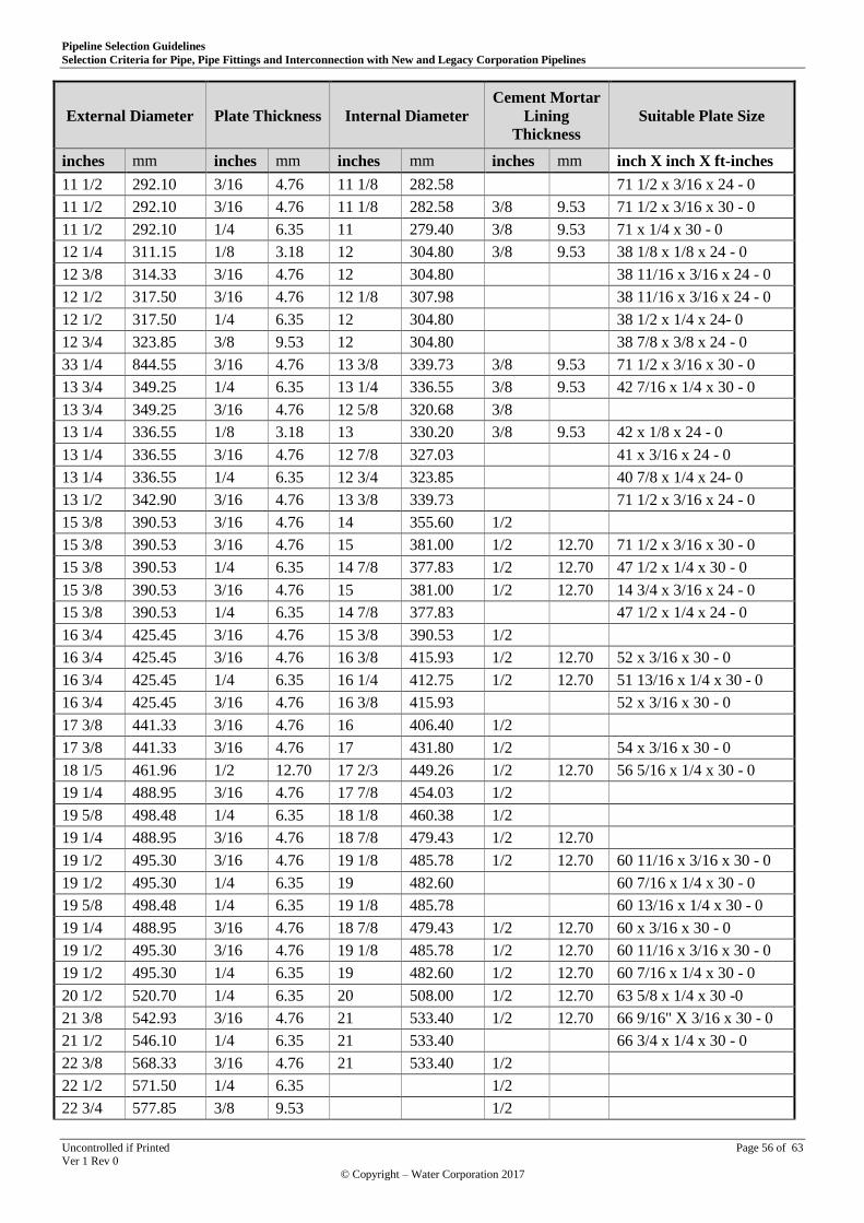
Pipeline Selection Guidelines
Selection Criteria for Pipe, Pipe Fittings and Interconnection with New and Legacy Corporation Pipelines
Uncontrolled if Printed Page 56 of 63 Ver 1 Rev 0
© Copyright – Water Corporation 2017
External Diameter Plate Thickness Internal Diameter
Cement Mortar
Lining
Thickness
Suitable Plate Size
inches mm inches mm inches mm inches mm inch X inch X ft-inches
11 1/2 292.10 3/16 4.76 11 1/8 282.58 71 1/2 x 3/16 x 24 - 0
11 1/2 292.10 3/16 4.76 11 1/8 282.58 3/8 9.53 71 1/2 x 3/16 x 30 - 0
11 1/2 292.10 1/4 6.35 11 279.40 3/8 9.53 71 x 1/4 x 30 - 0
12 1/4 311.15 1/8 3.18 12 304.80 3/8 9.53 38 1/8 x 1/8 x 24 - 0
12 3/8 314.33 3/16 4.76 12 304.80 38 11/16 x 3/16 x 24 - 0
12 1/2 317.50 3/16 4.76 12 1/8 307.98 38 11/16 x 3/16 x 24 - 0
12 1/2 317.50 1/4 6.35 12 304.80 38 1/2 x 1/4 x 24- 0
12 3/4 323.85 3/8 9.53 12 304.80 38 7/8 x 3/8 x 24 - 0
33 1/4 844.55 3/16 4.76 13 3/8 339.73 3/8 9.53 71 1/2 x 3/16 x 30 - 0
13 3/4 349.25 1/4 6.35 13 1/4 336.55 3/8 9.53 42 7/16 x 1/4 x 30 - 0
13 3/4 349.25 3/16 4.76 12 5/8 320.68 3/8
13 1/4 336.55 1/8 3.18 13 330.20 3/8 9.53 42 x 1/8 x 24 - 0
13 1/4 336.55 3/16 4.76 12 7/8 327.03 41 x 3/16 x 24 - 0
13 1/4 336.55 1/4 6.35 12 3/4 323.85 40 7/8 x 1/4 x 24- 0
13 1/2 342.90 3/16 4.76 13 3/8 339.73 71 1/2 x 3/16 x 24 - 0
15 3/8 390.53 3/16 4.76 14 355.60 1/2
15 3/8 390.53 3/16 4.76 15 381.00 1/2 12.70 71 1/2 x 3/16 x 30 - 0
15 3/8 390.53 1/4 6.35 14 7/8 377.83 1/2 12.70 47 1/2 x 1/4 x 30 - 0
15 3/8 390.53 3/16 4.76 15 381.00 1/2 12.70 14 3/4 x 3/16 x 24 - 0
15 3/8 390.53 1/4 6.35 14 7/8 377.83 47 1/2 x 1/4 x 24 - 0
16 3/4 425.45 3/16 4.76 15 3/8 390.53 1/2
16 3/4 425.45 3/16 4.76 16 3/8 415.93 1/2 12.70 52 x 3/16 x 30 - 0
16 3/4 425.45 1/4 6.35 16 1/4 412.75 1/2 12.70 51 13/16 x 1/4 x 30 - 0
16 3/4 425.45 3/16 4.76 16 3/8 415.93 52 x 3/16 x 30 - 0
17 3/8 441.33 3/16 4.76 16 406.40 1/2
17 3/8 441.33 3/16 4.76 17 431.80 1/2 54 x 3/16 x 30 - 0
18 1/5 461.96 1/2 12.70 17 2/3 449.26 1/2 12.70 56 5/16 x 1/4 x 30 - 0
19 1/4 488.95 3/16 4.76 17 7/8 454.03 1/2
19 5/8 498.48 1/4 6.35 18 1/8 460.38 1/2
19 1/4 488.95 3/16 4.76 18 7/8 479.43 1/2 12.70
19 1/2 495.30 3/16 4.76 19 1/8 485.78 1/2 12.70 60 11/16 x 3/16 x 30 - 0
19 1/2 495.30 1/4 6.35 19 482.60 60 7/16 x 1/4 x 30 - 0
19 5/8 498.48 1/4 6.35 19 1/8 485.78 60 13/16 x 1/4 x 30 - 0
19 1/4 488.95 3/16 4.76 18 7/8 479.43 1/2 12.70 60 x 3/16 x 30 - 0
19 1/2 495.30 3/16 4.76 19 1/8 485.78 1/2 12.70 60 11/16 x 3/16 x 30 - 0
19 1/2 495.30 1/4 6.35 19 482.60 1/2 12.70 60 7/16 x 1/4 x 30 - 0
20 1/2 520.70 1/4 6.35 20 508.00 1/2 12.70 63 5/8 x 1/4 x 30 -0
21 3/8 542.93 3/16 4.76 21 533.40 1/2 12.70 66 9/16" X 3/16 x 30 - 0
21 1/2 546.10 1/4 6.35 21 533.40 66 3/4 x 1/4 x 30 - 0
22 3/8 568.33 3/16 4.76 21 533.40 1/2
22 1/2 571.50 1/4 6.35 1/2
22 3/4 577.85 3/8 9.53 1/2

Pipeline Selection Guidelines
Selection Criteria for Pipe, Pipe Fittings and Interconnection with New and Legacy Corporation Pipelines
Uncontrolled if Printed Page 57 of 63 Ver 1 Rev 0
© Copyright – Water Corporation 2017
External Diameter Plate Thickness Internal Diameter
Cement Mortar
Lining
Thickness
Suitable Plate Size
inches mm inches mm inches mm inches mm inch X inch X ft-inches
22 3/8 568.33 3/16 4.76 22 558.80 1/2 12.70 60 x 3/16 x 29 x 0 1/2
22 1/2 571.50 1/4 6.35 22 558.80 1/2 12.70 69 7/8 x 1/74 x 30 - 0
22 3/4 577.85 3/8 9.53 22 558.80 1/2 12.70 72 x 3/8 x 23 - 6
22 3/8 568.33 3/16 4.76 22 558.80 1/2 12.70 60 x 3/16 x 29 - 0 1/2
22 1/2 571.50 1/4 6.35 22 558.80
68 7/8 x 1/4 x 30 - 0
22 3/4 577.85 1/4 6.35 22 1/4 565.15
70 5/8 x 1/4 x 30 - 0
22 3/4 577.85 3/8 9.53 22 558.80
72 3/8 x 23 - 6
24 1/2 622.30 1/4 6.35 24 609.60 1/2 12.70 72 x 1/4 x 25 - 4 1/2
25 1/2 647.70 1/4 6.35 25 635.00 1/2 12.70 72 x 1/4 x 26 -5 1/4
25 3/8 644.53 3/16 4.76 25 635.00 1/2 12.70 72 x 3/16 x 26 - 4 1/2
25 1/2 647.70 1/4 6.35 25 635.00 1/2 12.70 72 x 1/4 x 26 -5 1/4
25 1/2 647.70 1/4 6.35 24 609.60 1/2
28 1/2 723.90
27 685.80
30 1/2 774.70 1/4 6.35 30 762.00 1/2 12.70 72 x 1/4 x 23 - 9
30 3/4 781.05 5/16 7.94 30 762.00
72 x 5/16 x 23 -9 5/8
30 762.00 3/8 9.53 29 1/4 742.95 1/2 12.70 72 x 3/8 x 23 - 3 1/4
31 1/2 800.10 1/4 6.35 30 762.00 1/2
31 5/8 803.28 5/16 7.94 30 762.00 1/2
31 1/2 800.10 1/4 6.35 31 787.40 1/2 12.70 72 x 1/4 24 - 6 5/8
31 5/8 803.28 5/16 7.94 31 787.40 1/2 12.70 72 x 5/16 x 24 -7
31 3/4 806.45 3/8 9.53 31 787.40 1/2 12.70 72 x 3/8 x 24 - 7 3/4
31 1/2 800.10 1/4 6.35 31 787.40
72 x 5/16 x 24 - 6 5/8
31 5/8 803.28 1/4 6.35 31 1/8 790.58 1/2 12.70 72 x 1/4 x 24 - 7 5 3/4
31 5/8 803.28 5/16 7.94 31 787.40
72 x 5/16 x 24-7
31 3/4 806.45 5/16 7.94 31 1/8 790.58
72 x 5/16 x 24 -8 1/4
31 3/4 806.45 3/8 9.53 31 787.40
72 x 3/8 x 24 - 7 3/4
34 7/8 885.83 5/16 7.94 33 1/4 844.55 1/2
34 5/8 879.48 5/16 7.94 34 863.60 5/8 15.88 72 x 5/16 x 26 - 11 1/2
34 7/8 885.83 9/16 14.11 34 1/4 869.95
72 x 5/16 x 27 - 3/4
36 1/2 927.10 1/4 6.35 36 914.40 5/8 15.88 72 x 1/4 x 28 -5 3/4
36 5/8 930.28 5/16 7.94 36 914.40
72 x 5/16 X 28 - 6 1/4
36 3/4 933.45 3/8 9.53 36 914.40
72 x 3/8 x 19 - 0 1/2
37 3/4 958.85 1/4 6.35 37 1/4 946.15
72 x 1/4 x 19 - 7 5/8
37 3/4 958.85 3/16 4.76 37 1/8 942.98 5/8 15.88 72 x 5/16 x 29 - 4 1/8
37 3/4 958.85 3/8 9.53 37 939.80
72 x 3/8 x 19 - 6 7/8
37 1/4 946.15 5/16 7.94 37 1/4 946.15
72 x 5/16 x 19 - 8
37 3/4 958.85 1/4 6.35 37 1/4 946.15 5/8 15.88 72 x 1/4 x 19 - 7 5/8
37 3/4 958.85 3/8 9.53 37 939.80 5/8 15.88 72 x 3/8 x 19 -6 7/8
37 7/8 962.03 5/16 7.94 37 1/4 946.15 5/8 72 x 5/16 x 19 -8
38 965.20 3/8 9.53 36 914.40 5/8
38 965.20 3/8 9.53 37 1/4 946.15 5/8 15.88 72 x 3/8 x 19 - 8 1/2
38 3/8 974.73 9/16 14.29 37 1/4 946.15 72 x 9/16 x 19 - 9 1/2
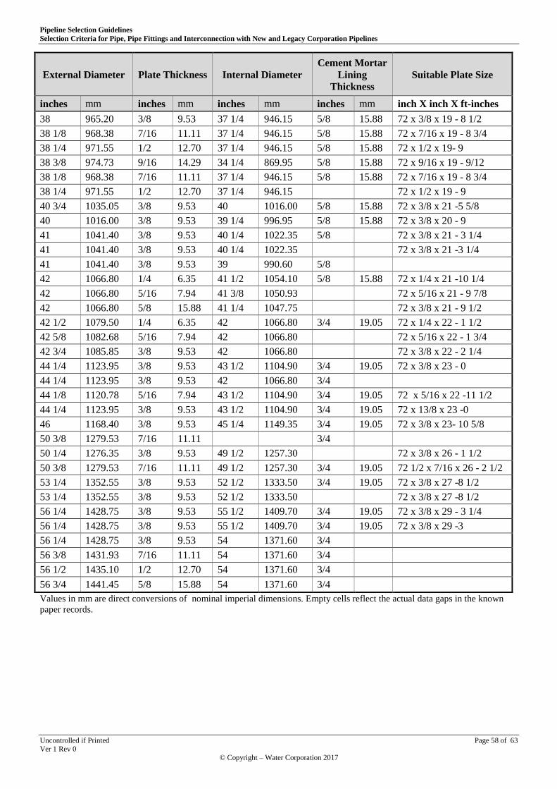
Pipeline Selection Guidelines
Selection Criteria for Pipe, Pipe Fittings and Interconnection with New and Legacy Corporation Pipelines
Uncontrolled if Printed Page 58 of 63 Ver 1 Rev 0
© Copyright – Water Corporation 2017
External Diameter Plate Thickness Internal Diameter
Cement Mortar
Lining
Thickness
Suitable Plate Size
inches mm inches mm inches mm inches mm inch X inch X ft-inches
38 965.20 3/8 9.53 37 1/4 946.15 5/8 15.88 72 x 3/8 x 19 - 8 1/2
38 1/8 968.38 7/16 11.11 37 1/4 946.15 5/8 15.88 72 x 7/16 x 19 - 8 3/4
38 1/4 971.55 1/2 12.70 37 1/4 946.15 5/8 15.88 72 x 1/2 x 19- 9
38 3/8 974.73 9/16 14.29 34 1/4 869.95 5/8 15.88 72 x 9/16 x 19 - 9/12
38 1/8 968.38 7/16 11.11 37 1/4 946.15 5/8 15.88 72 x 7/16 x 19 - 8 3/4
38 1/4 971.55 1/2 12.70 37 1/4 946.15 72 x 1/2 x 19 - 9
40 3/4 1035.05 3/8 9.53 40 1016.00 5/8 15.88 72 x 3/8 x 21 -5 5/8
40 1016.00 3/8 9.53 39 1/4 996.95 5/8 15.88 72 x 3/8 x 20 - 9
41 1041.40 3/8 9.53 40 1/4 1022.35 5/8 72 x 3/8 x 21 - 3 1/4
41 1041.40 3/8 9.53 40 1/4 1022.35 72 x 3/8 x 21 -3 1/4
41 1041.40 3/8 9.53 39 990.60 5/8
42 1066.80 1/4 6.35 41 1/2 1054.10 5/8 15.88 72 x 1/4 x 21 -10 1/4
42 1066.80 5/16 7.94 41 3/8 1050.93 72 x 5/16 x 21 - 9 7/8
42 1066.80 5/8 15.88 41 1/4 1047.75 72 x 3/8 x 21 - 9 1/2
42 1/2 1079.50 1/4 6.35 42 1066.80 3/4 19.05 72 x 1/4 x 22 - 1 1/2
42 5/8 1082.68 5/16 7.94 42 1066.80 72 x 5/16 x 22 - 1 3/4
42 3/4 1085.85 3/8 9.53 42 1066.80 72 x 3/8 x 22 - 2 1/4
44 1/4 1123.95 3/8 9.53 43 1/2 1104.90 3/4 19.05 72 x 3/8 x 23 - 0
44 1/4 1123.95 3/8 9.53 42 1066.80 3/4
44 1/8 1120.78 5/16 7.94 43 1/2 1104.90 3/4 19.05 72 x 5/16 x 22 -11 1/2
44 1/4 1123.95 3/8 9.53 43 1/2 1104.90 3/4 19.05 72 x 13/8 x 23 -0
46 1168.40 3/8 9.53 45 1/4 1149.35 3/4 19.05 72 x 3/8 x 23- 10 5/8
50 3/8 1279.53 7/16 11.11 3/4
50 1/4 1276.35 3/8 9.53 49 1/2 1257.30 72 x 3/8 x 26 - 1 1/2
50 3/8 1279.53 7/16 11.11 49 1/2 1257.30 3/4 19.05 72 1/2 x 7/16 x 26 - 2 1/2
53 1/4 1352.55 3/8 9.53 52 1/2 1333.50 3/4 19.05 72 x 3/8 x 27 -8 1/2
53 1/4 1352.55 3/8 9.53 52 1/2 1333.50 72 x 3/8 x 27 -8 1/2
56 1/4 1428.75 3/8 9.53 55 1/2 1409.70 3/4 19.05 72 x 3/8 x 29 - 3 1/4
56 1/4 1428.75 3/8 9.53 55 1/2 1409.70 3/4 19.05 72 x 3/8 x 29 -3
56 1/4 1428.75 3/8 9.53 54 1371.60 3/4
56 3/8 1431.93 7/16 11.11 54 1371.60 3/4
56 1/2 1435.10 1/2 12.70 54 1371.60 3/4
56 3/4 1441.45 5/8 15.88 54 1371.60 3/4
Values in mm are direct conversions of nominal imperial dimensions. Empty cells reflect the actual data gaps in the known
paper records.

Pipeline Selection Guidelines
Selection Criteria for Pipe, Pipe Fittings and Interconnection with New and Legacy Corporation Pipelines
Uncontrolled if Printed Page 59 of 63 Ver 1 Rev 0
© Copyright – Water Corporation 2017
APPENDIX E
Table E1 Reinforced Concrete Pressure Pipe - Dimensions - MWSS & DD
Nominal
Diameter
(Inches)
Test Pressure
PSI
Internal
Diameter
(Inches)
External Diameter
OD (Inches/mm)
Effective
Length
(Feet)
total length
(Feet & Inches)
Weight
(lbs)
in mm
4 50, 75, 100, 115, 120, 135, 180 4 6 1/4 158.75 6 6 - 2 1/2 138
6 50, 75, 100, 115, 120, 135 6 8 1/4 209.55 6 6 - 2 1/2 190
6 180 5 1/2 8 1/4 209.55 6 6- 2 1/2
8 50, 75, 100, 115, 120, 135 8 3/4 11 1/2 292.10 6 6 - 2 3/4
180 8 1/2 12 1/4 311.15 6 6-3 1/4
10 50, 75 10 12 1/2 317.50 6 6-2 3/4 328
100 10 13 1/4 336.55 6 6-3" 446
12 50, 75 12 15 381.00 6 0-3 475
100, 115 11 1/2 15 381.00 6 6-3"
120 11 1/2 15 381.00 8 8-3"
135 11 15 381.00 8 8-3"
15 50 15 17 1/2 444.50 8 8-2 3/4 611
120 15 19 1/2 495.30 8 8-3" 1188
18 50, 75 18 23 1/2 596.90 8 8- 3 1/2 1780
115, 120 17 1/2 23 1/2 596.90 8 8 - 3 1/2
21 50, 75 20 3/4 25 635.00 8 8-3 1/2
100, 115 20 25 635.00 8 8-3 1/2 1685
24 50 24 28 1/2 723.90 8 8 - 3 1/2 1812
80 23 3/4 28 1/2 723.90 8 8-3 1/2 2058
100 23 3/4 30 762.00 8 8- 4 1/4 2716
115, 120 23 1/2 30 762.00 8 8-4 1/4
30 50 30 34 863.60 8 8-3 7/8
75 28 7/8 34 863.60 8 8-3 7/8 2465
100 29 36 914.40 8 8-3 7/8 3410
Equivalent metric values are direct conversions of nominal imperial values.

Pipeline Selection Guidelines
Selection Criteria for Pipe, Pipe Fittings and Interconnection with New and Legacy Corporation Pipelines
Uncontrolled if Printed Page 60 of 63 Ver 1 Rev 0
© Copyright – Water Corporation 2017
Table E2 RC Pressure Pipe Dimensions - Humes Ltd
Equivalent Metric Dimensions Imperial Dimensions
External
Diameter
Internal
Diameter
Wall
Thickness
Test Pressure Effective
Length
Internal
Diameter
Wall
Thickness
Test Pressure Effective
Length
mm mm mm KPa m Inches Inches PSI Feet
160 102 29 930 1.83 4 1 1/8 135 6
160 102 29 1241 1.83 4 1 1/8 180 6
210 152 29 930 1.83 6 1 1/8 135 6
210 140 35 1241 1.83 5 1/2 1 3/8 180 6
292 222 35 930 1.83 8 3/4 1 3/8 135 6
312 216 48 1241 1.83 8 1/2 1 7/8 180 6
381 305 38 345 2.44 12 1 1/2 50 8
380 292 44 827 2.44 11 1/2 1 3/4 120 8
381 279 51 930 2.44 11 2 135 8
597 495 51 517 2.44 19 1/2 2 75 8
596 444 76 827 2.44 17 1/2 3 120 8
635 527 54 345 2.44 20 3/4 2 1/8 50 8
636 508 64 689 2.44 20 2 1/2 100 8
724 610 57 345 2.44 24 2 1/4 50 8
725 597 64 517 2.44 23 1/2 2 1/2 75 8
761 603 79 689 2.44 23 3/4 3 1/8 100 8
763 597 83 827 2.44 23 1/2 3 1/4 120 8
864 762 51 345 2.44 30 2 50 8
914 762 76 517 2.44 30 3 75 8
915 737 89 689 2.44 29 3 1/2 100 8
915 711 102 827 2.44 28 4 120 8
1092 914 89 517 2.44 36 3 1/2 75 8
Equivalent metric values are direct conversions of nominal imperial values.
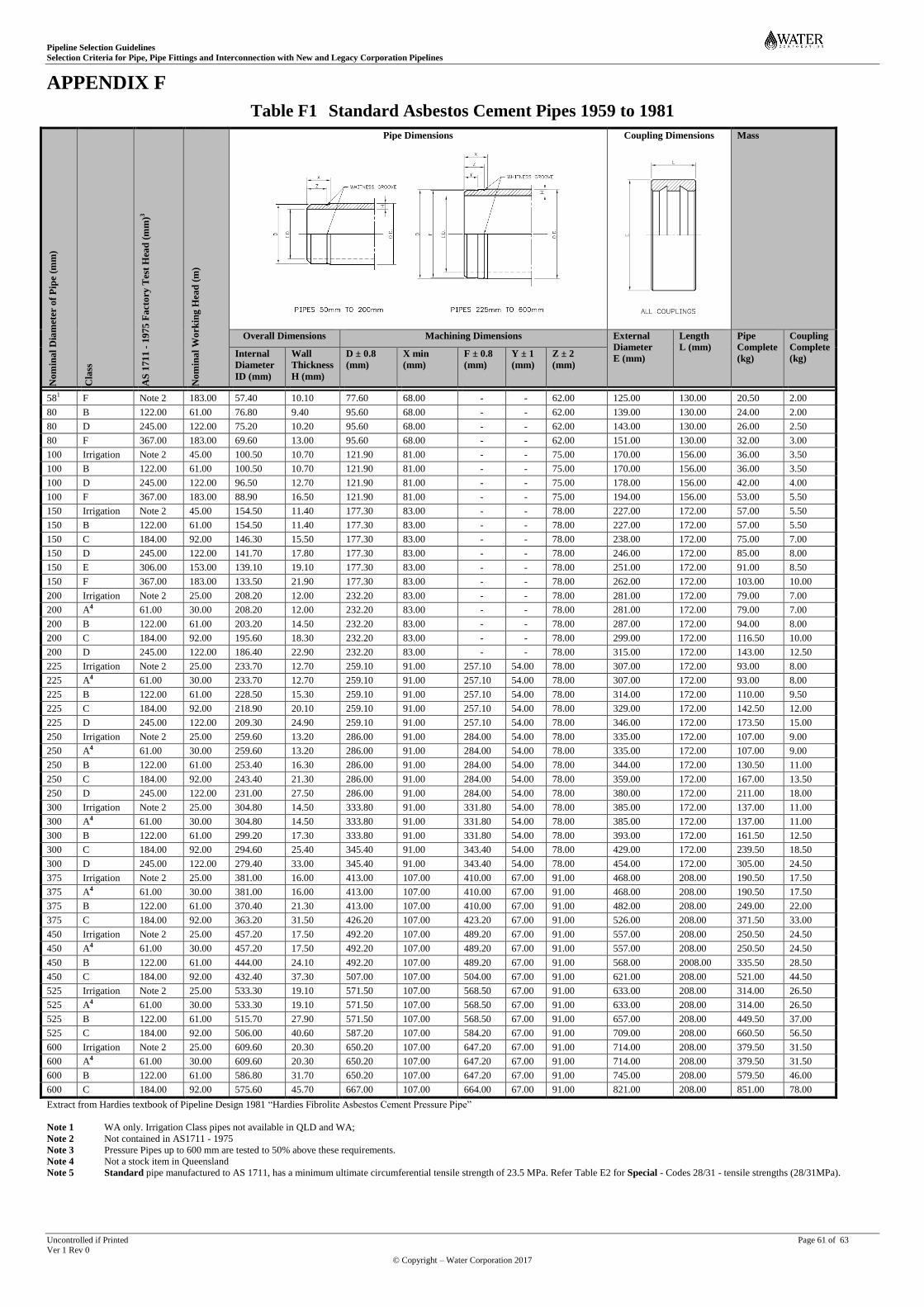
Pipeline Selection Guidelines
Selection Criteria for Pipe, Pipe Fittings and Interconnection with New and Legacy Corporation Pipelines
Uncontrolled if Printed Page 61 of 63 Ver 1 Rev 0
© Copyright – Water Corporation 2017
APPENDIX F
Table F1 Standard Asbestos Cement Pipes 1959 to 1981
No
min
al
Dia
met
er o
f P
ipe
(mm
)
Cla
ss
AS
171
1 -
19
75
Fa
cto
ry T
est
Hea
d (
mm
)3
No
min
al
Wo
rkin
g H
ead
(m
)
Pipe Dimensions
Coupling Dimensions
Mass
Overall Dimensions Machining Dimensions External
Diameter
E (mm)
Length
L (mm)
Pipe
Complete
(kg)
Coupling
Complete
(kg) Internal
Diameter
ID (mm)
Wall
Thickness
H (mm)
D ± 0.8
(mm)
X min
(mm)
F ± 0.8
(mm)
Y ± 1
(mm)
Z ± 2
(mm)
581 F Note 2 183.00 57.40 10.10 77.60 68.00 - - 62.00 125.00 130.00 20.50 2.00
80 B 122.00 61.00 76.80 9.40 95.60 68.00 - - 62.00 139.00 130.00 24.00 2.00
80 D 245.00 122.00 75.20 10.20 95.60 68.00 - - 62.00 143.00 130.00 26.00 2.50
80 F 367.00 183.00 69.60 13.00 95.60 68.00 - - 62.00 151.00 130.00 32.00 3.00
100 Irrigation Note 2 45.00 100.50 10.70 121.90 81.00 - - 75.00 170.00 156.00 36.00 3.50
100 B 122.00 61.00 100.50 10.70 121.90 81.00 - - 75.00 170.00 156.00 36.00 3.50
100 D 245.00 122.00 96.50 12.70 121.90 81.00 - - 75.00 178.00 156.00 42.00 4.00
100 F 367.00 183.00 88.90 16.50 121.90 81.00 - - 75.00 194.00 156.00 53.00 5.50
150 Irrigation Note 2 45.00 154.50 11.40 177.30 83.00 - - 78.00 227.00 172.00 57.00 5.50
150 B 122.00 61.00 154.50 11.40 177.30 83.00 - - 78.00 227.00 172.00 57.00 5.50
150 C 184.00 92.00 146.30 15.50 177.30 83.00 - - 78.00 238.00 172.00 75.00 7.00
150 D 245.00 122.00 141.70 17.80 177.30 83.00 - - 78.00 246.00 172.00 85.00 8.00
150 E 306.00 153.00 139.10 19.10 177.30 83.00 - - 78.00 251.00 172.00 91.00 8.50
150 F 367.00 183.00 133.50 21.90 177.30 83.00 - - 78.00 262.00 172.00 103.00 10.00
200 Irrigation Note 2 25.00 208.20 12.00 232.20 83.00 - - 78.00 281.00 172.00 79.00 7.00
200 A4 61.00 30.00 208.20 12.00 232.20 83.00 - - 78.00 281.00 172.00 79.00 7.00
200 B 122.00 61.00 203.20 14.50 232.20 83.00 - - 78.00 287.00 172.00 94.00 8.00
200 C 184.00 92.00 195.60 18.30 232.20 83.00 - - 78.00 299.00 172.00 116.50 10.00
200 D 245.00 122.00 186.40 22.90 232.20 83.00 - - 78.00 315.00 172.00 143.00 12.50
225 Irrigation Note 2 25.00 233.70 12.70 259.10 91.00 257.10 54.00 78.00 307.00 172.00 93.00 8.00
225 A4 61.00 30.00 233.70 12.70 259.10 91.00 257.10 54.00 78.00 307.00 172.00 93.00 8.00
225 B 122.00 61.00 228.50 15.30 259.10 91.00 257.10 54.00 78.00 314.00 172.00 110.00 9.50
225 C 184.00 92.00 218.90 20.10 259.10 91.00 257.10 54.00 78.00 329.00 172.00 142.50 12.00
225 D 245.00 122.00 209.30 24.90 259.10 91.00 257.10 54.00 78.00 346.00 172.00 173.50 15.00
250 Irrigation Note 2 25.00 259.60 13.20 286.00 91.00 284.00 54.00 78.00 335.00 172.00 107.00 9.00
250 A4 61.00 30.00 259.60 13.20 286.00 91.00 284.00 54.00 78.00 335.00 172.00 107.00 9.00
250 B 122.00 61.00 253.40 16.30 286.00 91.00 284.00 54.00 78.00 344.00 172.00 130.50 11.00
250 C 184.00 92.00 243.40 21.30 286.00 91.00 284.00 54.00 78.00 359.00 172.00 167.00 13.50
250 D 245.00 122.00 231.00 27.50 286.00 91.00 284.00 54.00 78.00 380.00 172.00 211.00 18.00
300 Irrigation Note 2 25.00 304.80 14.50 333.80 91.00 331.80 54.00 78.00 385.00 172.00 137.00 11.00
300 A4 61.00 30.00 304.80 14.50 333.80 91.00 331.80 54.00 78.00 385.00 172.00 137.00 11.00
300 B 122.00 61.00 299.20 17.30 333.80 91.00 331.80 54.00 78.00 393.00 172.00 161.50 12.50
300 C 184.00 92.00 294.60 25.40 345.40 91.00 343.40 54.00 78.00 429.00 172.00 239.50 18.50
300 D 245.00 122.00 279.40 33.00 345.40 91.00 343.40 54.00 78.00 454.00 172.00 305.00 24.50
375 Irrigation Note 2 25.00 381.00 16.00 413.00 107.00 410.00 67.00 91.00 468.00 208.00 190.50 17.50
375 A4 61.00 30.00 381.00 16.00 413.00 107.00 410.00 67.00 91.00 468.00 208.00 190.50 17.50
375 B 122.00 61.00 370.40 21.30 413.00 107.00 410.00 67.00 91.00 482.00 208.00 249.00 22.00
375 C 184.00 92.00 363.20 31.50 426.20 107.00 423.20 67.00 91.00 526.00 208.00 371.50 33.00
450 Irrigation Note 2 25.00 457.20 17.50 492.20 107.00 489.20 67.00 91.00 557.00 208.00 250.50 24.50
450 A4 61.00 30.00 457.20 17.50 492.20 107.00 489.20 67.00 91.00 557.00 208.00 250.50 24.50
450 B 122.00 61.00 444.00 24.10 492.20 107.00 489.20 67.00 91.00 568.00 2008.00 335.50 28.50
450 C 184.00 92.00 432.40 37.30 507.00 107.00 504.00 67.00 91.00 621.00 208.00 521.00 44.50
525 Irrigation Note 2 25.00 533.30 19.10 571.50 107.00 568.50 67.00 91.00 633.00 208.00 314.00 26.50
525 A4 61.00 30.00 533.30 19.10 571.50 107.00 568.50 67.00 91.00 633.00 208.00 314.00 26.50
525 B 122.00 61.00 515.70 27.90 571.50 107.00 568.50 67.00 91.00 657.00 208.00 449.50 37.00
525 C 184.00 92.00 506.00 40.60 587.20 107.00 584.20 67.00 91.00 709.00 208.00 660.50 56.50
600 Irrigation Note 2 25.00 609.60 20.30 650.20 107.00 647.20 67.00 91.00 714.00 208.00 379.50 31.50
600 A4 61.00 30.00 609.60 20.30 650.20 107.00 647.20 67.00 91.00 714.00 208.00 379.50 31.50
600 B 122.00 61.00 586.80 31.70 650.20 107.00 647.20 67.00 91.00 745.00 208.00 579.50 46.00
600 C 184.00 92.00 575.60 45.70 667.00 107.00 664.00 67.00 91.00 821.00 208.00 851.00 78.00
Extract from Hardies textbook of Pipeline Design 1981 “Hardies Fibrolite Asbestos Cement Pressure Pipe”
Note 1 WA only. Irrigation Class pipes not available in QLD and WA;
Note 2 Not contained in AS1711 - 1975
Note 3 Pressure Pipes up to 600 mm are tested to 50% above these requirements.
Note 4 Not a stock item in Queensland
Note 5 Standard pipe manufactured to AS 1711, has a minimum ultimate circumferential tensile strength of 23.5 MPa. Refer Table E2 for Special - Codes 28/31 - tensile strengths (28/31MPa).
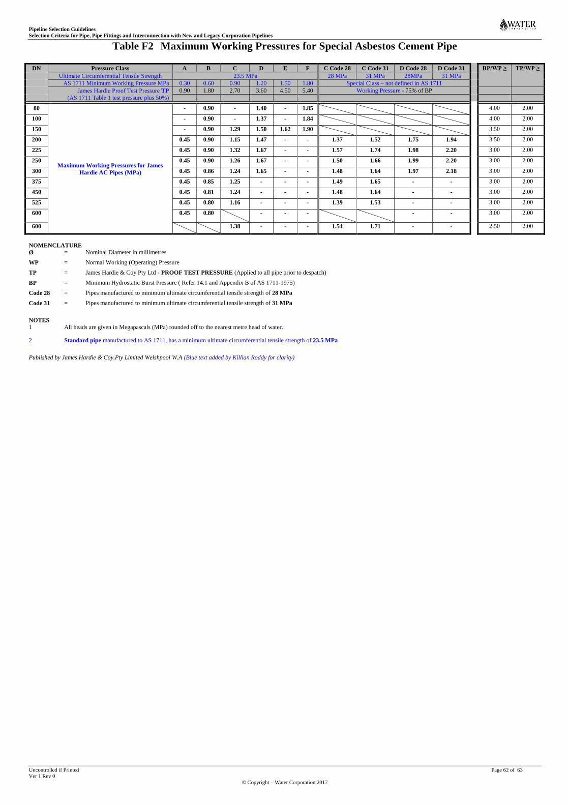
Pipeline Selection Guidelines
Selection Criteria for Pipe, Pipe Fittings and Interconnection with New and Legacy Corporation Pipelines
Uncontrolled if Printed Page 62 of 63 Ver 1 Rev 0
© Copyright – Water Corporation 2017
Table F2 Maximum Working Pressures for Special Asbestos Cement Pipe
DN Pressure Class A B C D E F C Code 28 C Code 31 D Code 28 D Code 31 BP/WP ≥ TP/WP ≥
Ultimate Circumferential Tensile Strength 23.5 MPa 28 MPa 31 MPa 28MPa 31 MPa
AS 1711 Minimum Working Pressure MPa 0.30 0.60 0.90 1.20 1.50 1.80 Special Class – not defined in AS 1711
James Hardie Proof Test Pressure TP
(AS 1711 Table 1 test pressure plus 50%)
0.90 1.80 2.70 3.60 4.50 5.40 Working Pressure - 75% of BP
80
Maximum Working Pressures for James
Hardie AC Pipes (MPa)
- 0.90 - 1.40 - 1.85 4.00 2.00
100 - 0.90 - 1.37 - 1.84 4.00 2.00
150 - 0.90 1.29 1.50 1.62 1.90 3.50 2.00
200 0.45 0.90 1.15 1.47 - - 1.37 1.52 1.75 1.94 3.50 2.00
225 0.45 0.90 1.32 1.67 - - 1.57 1.74 1.98 2.20 3.00 2.00
250 0.45 0.90 1.26 1.67 - - 1.50 1.66 1.99 2.20 3.00 2.00
300 0.45 0.86 1.24 1.65 - - 1.48 1.64 1.97 2.18 3.00 2.00
375 0.45 0.85 1.25 - - - 1.49 1.65 - - 3.00 2.00
450 0.45 0.81 1.24 - - - 1.48 1.64 - - 3.00 2.00
525 0.45 0.80 1.16 - - - 1.39 1.53 - - 3.00 2.00
600 0.45 0.80 - - - - - 3.00 2.00
600 1.38 - - - 1.54 1.71 - - 2.50 2.00
NOMENCLATURE
Ø = Nominal Diameter in millimetres
WP = Normal Working (Operating) Pressure
TP = James Hardie & Coy Pty Ltd - PROOF TEST PRESSURE (Applied to all pipe prior to despatch)
BP = Minimum Hydrostatic Burst Pressure ( Refer 14.1 and Appendix B of AS 1711-1975)
Code 28 = Pipes manufactured to minimum ultimate circumferential tensile strength of 28 MPa
Code 31 = Pipes manufactured to minimum ultimate circumferential tensile strength of 31 MPa
NOTES
1 All heads are given in Megapascals (MPa) rounded off to the nearest metre head of water.
2 Standard pipe manufactured to AS 1711, has a minimum ultimate circumferential tensile strength of 23.5 MPa
Published by James Hardie & Coy.Pty Limited Welshpool W.A (Blue text added by Killian Roddy for clarity)
Pipeline Selection Guidelines
Selection Criteria for Pipe, Pipe Fittings and Interconnection with New and Legacy Corporation Pipelines
Uncontrolled if Printed Page 63 of 63 Ver 1 Rev 0
© Copyright – Water Corporation 2017
END OF DOCUMENT
Top Related