


Languages
Pages
Legal

8/13/2019 Pipe Wall Thickness Calc IFA_A
http://slidepdf.com/reader/full/pipe-wall-thickness-calc-ifaa 1/32
FRONT END ENGINEERING DESIGN (FEED) MAKING
TOTAL PROJECT KAMOJANG UNIT 5 (1 x 30 MW) – WEST JAVA
CALCULATIONS OF PIPE WALL THICKNESS
AJune 26 ,
2012Issued for Approval RX GIB OOK TJA WDR
PREPARED CHECKED APPROVED CHECKED APPROVED
REV DATE DESCRIPTIONPT. LAPI ITB PT. PGE
STATUS CODE : IFR = Issued for Review, IFA = Issued for Approval, IFU = Issued for Use
Total or Partial Reproduction and/or utilization of this document are forbidden without prior written authorization of PT.PGE
DOCUMENT NUMBER REVISION STATUS
KMJ5-SG-PI-CSH-001 A IFA
8/13/2019 Pipe Wall Thickness Calc IFA_A
http://slidepdf.com/reader/full/pipe-wall-thickness-calc-ifaa 2/32
FRONT END ENGINEERING DESIGN (FEED) MAKINGTOTAL PROJECT KAMOJANG UNIT 5 (1 x 30 MW) –
WEST JAVA
TITLE DOCUMENT NUMBER PAGE
CALCULATION OF PIPE WALLTHICKNESS
KMJ5-SG-PI-CSH-001 2 OF 32
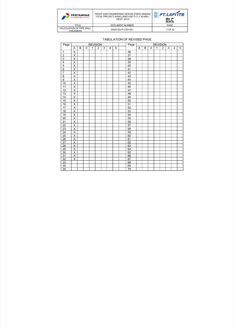
TABULATION OF REVISED PAGE
Page REVISION Page REVISION
A B 0 1 2 3 4 5 A B 0 1 2 3 4 5
1 X 36
2 X 37
3 X 38
4 X 39
5 X 40
6 X 41
7 X 42
8 X 43
9 X 44
10 X 4511 X 46
12 X 47
13 X 48
14 X 49
15 X 50
16 X 51
17 X 52
18 X 53
19 X 54
20 X 55
21 X 56
22 X 57
23 X 58
24 X 59
25 X 60
26 X 61
27 X 62
28 X 63
29 X 64
30 X 65
31 X 66
32 X 67
33 68
34 6935 70
8/13/2019 Pipe Wall Thickness Calc IFA_A
http://slidepdf.com/reader/full/pipe-wall-thickness-calc-ifaa 3/32
FRONT END ENGINEERING DESIGN (FEED) MAKINGTOTAL PROJECT KAMOJANG UNIT 5 (1 x 30 MW) –
WEST JAVA
TITLE DOCUMENT NUMBER PAGE
CALCULATION OF PIPE WALLTHICKNESS
KMJ5-SG-PI-CSH-001 3 OF 32
COMMENT SHEET
COMMENT:
NO
REFERENCE,
PARAGRAPH,
OR CHAPTER
COMMENT OF PT. PGE RESPONSE OF PT. LAPI ITB
COMPANY PT. PGE PT. LAPI ITB
BY <Name> <Name>
POSITION <Position> <Position>
DATE
DOCUMENT STATUS: IFR IFA IFU

8/13/2019 Pipe Wall Thickness Calc IFA_A
http://slidepdf.com/reader/full/pipe-wall-thickness-calc-ifaa 4/32
FRONT END ENGINEERING DESIGN (FEED) MAKINGTOTAL PROJECT KAMOJANG UNIT 5 (1 x 30 MW) –
WEST JAVA
TITLE DOCUMENT NUMBER PAGE
CALCULATION OF PIPE WALLTHICKNESS
KMJ5-SG-PI-CSH-001 4 OF 32
TABLE OF CONTENTS
1.
INTRODUCTION ..........................................................................................................5
2. PURPOSE ....................................................................................................................5
3. DEFINITION ..................................................................................................................5
4. CODE, STANDARD, DAN REFERENCES ..................................................................5
5. OPERATION DATA ......................................................................................................6
6. DESIGN DATA .............................................................................................................6
7. CALCULATION OF PIPE THICKNESS VERIFICATION .............................................7
7.1 CALCULATION OF PIPE WALL THICKNESS BASED ON ASME B31.1 TERMS
..........................................................................................................................7
7.2 MINIMUM THICKNESS (TMIN) OF PIPE WALL ................................................. 8
7.3 DESIGN PRESSURE (P) AND DESIGN TEMPERATURE (T) ......................... 8
7.4 PIPE OUTER DIAMETER (DO) .........................................................................8
7.5 ALLOWABLE STRESS VALUES BASED ON THE WORKING TEMPERATURE8
7.6
JOINT EFICIENCY (E) ......................................................................................8
7.7 CORROSION ALLOWANCES (CA) ..................................................................9
7.8 ADDITIONAL THICKNESS ...............................................................................9
7.9 MILL TOLERANCES .........................................................................................9
8. CALCULATION OF PIPE WALL THICKNESS RESULT AND PIPE SCHEDULE
SELECTION ............................................................................................................................. 9
PIPE WALL THICKNESS RESULT AND PIPE SCHEDULE SELECTION ...........................11
PIPE WALL THICKNESS CALCULATION SHEET ..............................................................12
8/13/2019 Pipe Wall Thickness Calc IFA_A
http://slidepdf.com/reader/full/pipe-wall-thickness-calc-ifaa 5/32
FRONT END ENGINEERING DESIGN (FEED) MAKINGTOTAL PROJECT KAMOJANG UNIT 5 (1 x 30 MW) –
WEST JAVA
TITLE DOCUMENT NUMBER PAGE
CALCULATION OF PIPE WALLTHICKNESS
KMJ5-SG-PI-CSH-001 5 OF 32
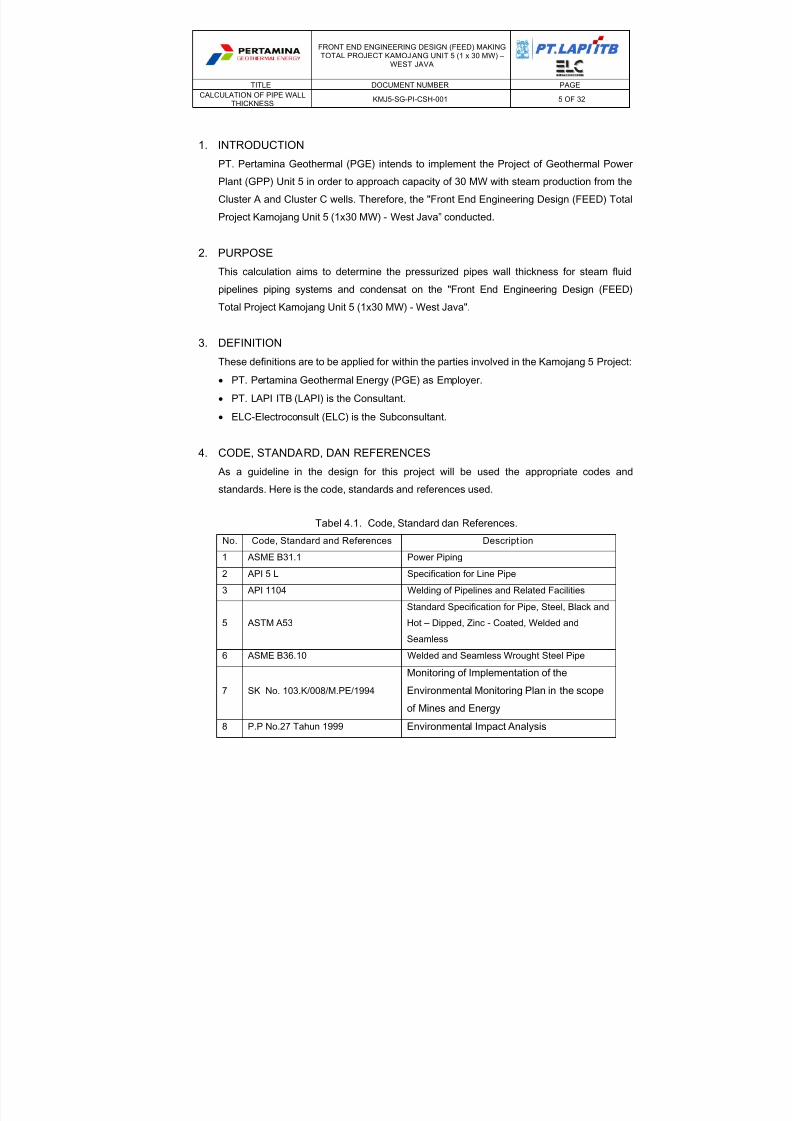
1. INTRODUCTION
PT. Pertamina Geothermal (PGE) intends to implement the Project of Geothermal Power
Plant (GPP) Unit 5 in order to approach capacity of 30 MW with steam production from the
Cluster A and Cluster C wells. Therefore, the "Front End Engineering Design (FEED) Total
Project Kamojang Unit 5 (1x30 MW) - West Java” conducted.
2. PURPOSE
This calculation aims to determine the pressurized pipes wall thickness for steam fluidpipelines piping systems and condensat on the "Front End Engineering Design (FEED)
Total Project Kamojang Unit 5 (1x30 MW) - West Java".
3. DEFINITION
These definitions are to be applied for within the parties involved in the Kamojang 5 Project:
PT. Pertamina Geothermal Energy (PGE) as Employer.
PT. LAPI ITB (LAPI) is the Consultant.
ELC-Electroconsult (ELC) is the Subconsultant.
4. CODE, STANDARD, DAN REFERENCES
As a guideline in the design for this project will be used the appropriate codes and
standards. Here is the code, standards and references used.
Tabel 4.1. Code, Standard dan References.
No. Code, Standard and References Descript ion
1 ASME B31.1 Power Piping
2 API 5 L Specification for Line Pipe
3 API 1104 Welding of Pipelines and Related Facilities
5 ASTM A53
Standard Specification for Pipe, Steel, Black and
Hot – Dipped, Zinc - Coated, Welded and
Seamless
6 ASME B36.10 Welded and Seamless Wrought Steel Pipe
7 SK No. 103.K/008/M.PE/1994
Monitoring of Implementation of the
Environmental Monitoring Plan in the scopeof Mines and Energy
8 P.P No.27 Tahun 1999 Environmental Impact Analysis
8/13/2019 Pipe Wall Thickness Calc IFA_A
http://slidepdf.com/reader/full/pipe-wall-thickness-calc-ifaa 6/32
FRONT END ENGINEERING DESIGN (FEED) MAKINGTOTAL PROJECT KAMOJANG UNIT 5 (1 x 30 MW) –
WEST JAVA
TITLE DOCUMENT NUMBER PAGE
CALCULATION OF PIPE WALLTHICKNESS
KMJ5-SG-PI-CSH-001 6 OF 32
No. Code, Standard and References Descript ion
9 API RP 581 Risk-Based Inspection Technology
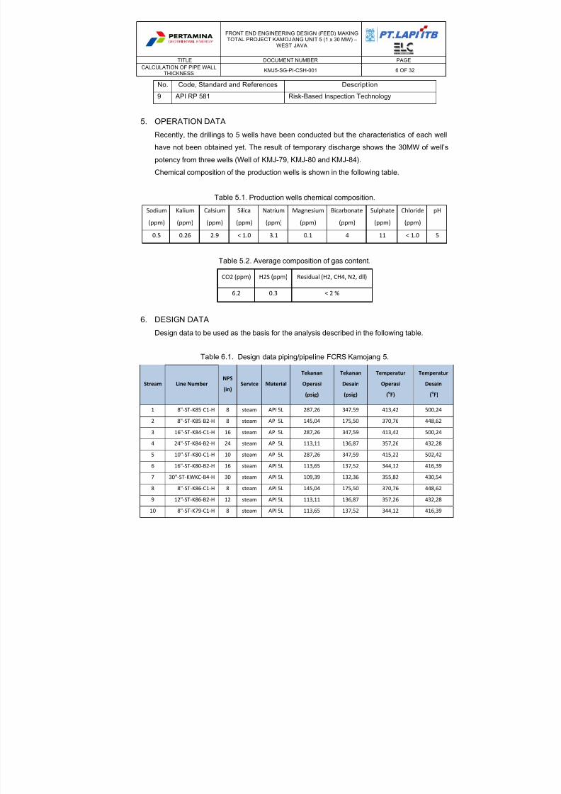
5. OPERATION DATA
Recently, the drillings to 5 wells have been conducted but the characteristics of each well
have not been obtained yet. The result of temporary discharge shows the 30MW of well’s
potency from three wells (Well of KMJ-79, KMJ-80 and KMJ-84).
Chemical composition of the production wells is shown in the following table.
Table 5.1. Production wells chemical composition.
Sodium
(ppm)
Kalium
(ppm)
Calsium
(ppm)
Silica
(ppm)
Natrium
(ppm)
Magnesium
(ppm)
Bicarbonate
(ppm)
Sulphate
(ppm)
Chloride
(ppm)
pH
0.5 0.26 2.9 < 1.0 3.1 0.1 4 11 < 1.0 5
Table 5.2. Average composition of gas content.
CO2 (ppm) H2S (ppm) Residual (H2, CH4, N2, dll)
6.2
0.3
< 2 %
6. DESIGN DATA
Design data to be used as the basis for the analysis described in the following table.
Table 6.1. Design data piping/pipeline FCRS Kamojang 5.
Stream Line Number NPS
(in) Service Material
Tekanan
Operasi
(psig)
Tekanan
Desain
(psig)
Temperatur
Operasi
(oF)
Temperatur
Desain
(oF)
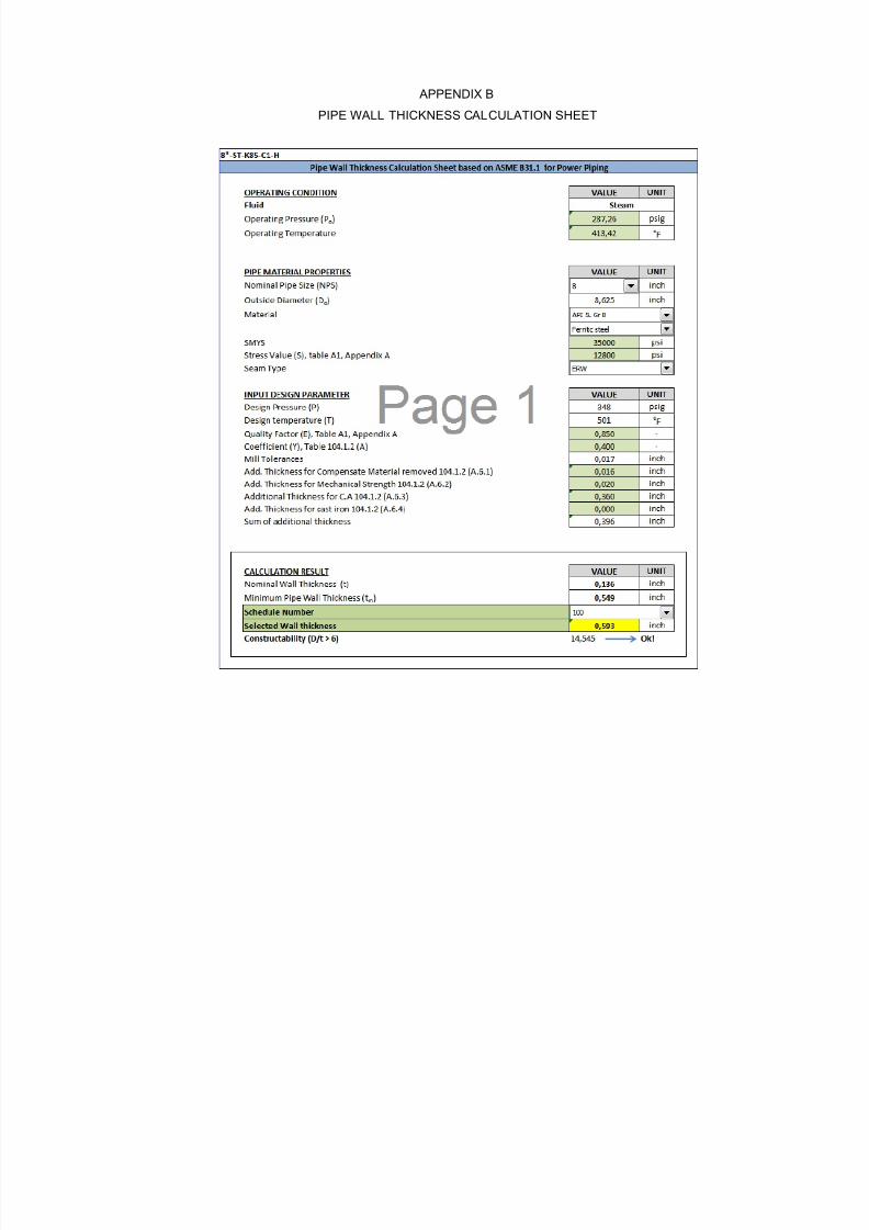
1 8"‐ST‐K85‐C1‐H 8 steam API 5L 287,26 347,59 413,42 500,24
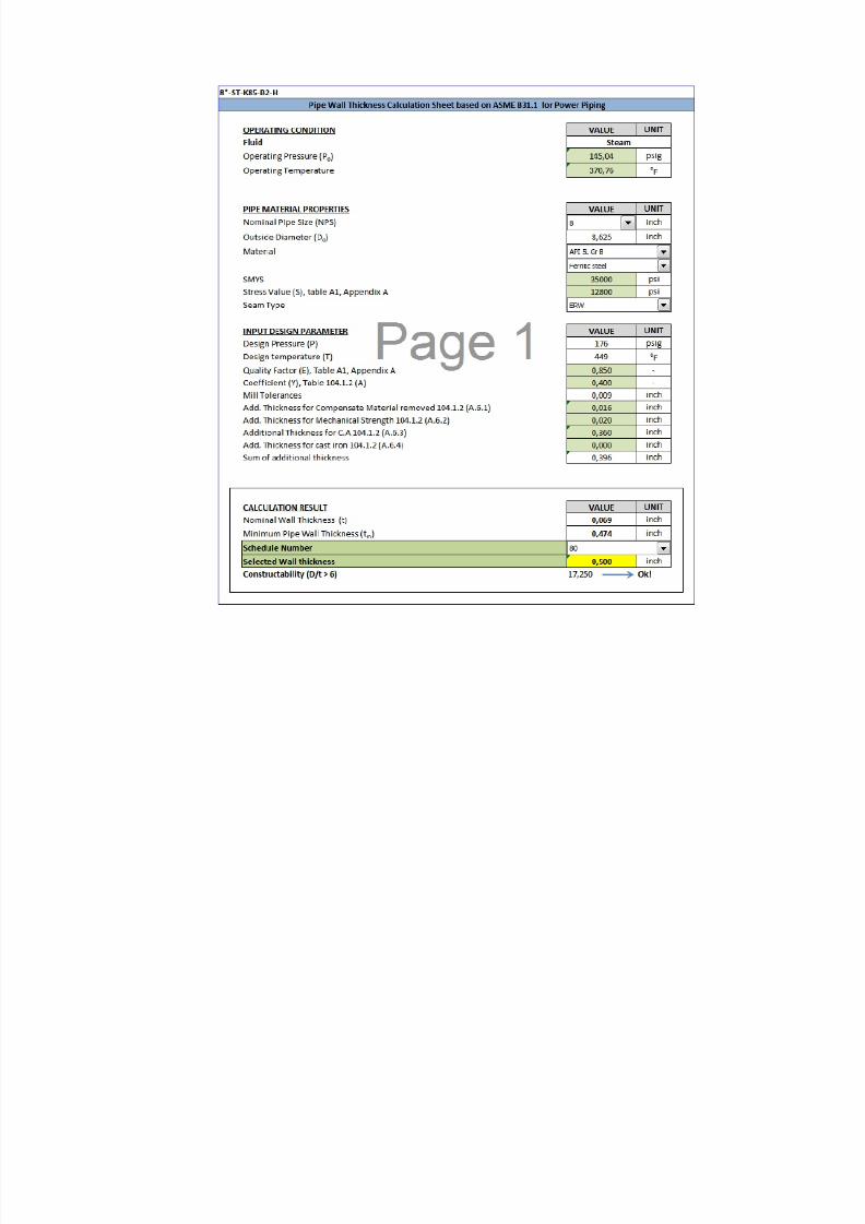
2 8"‐ST‐K85‐B2‐H 8 steam API 5L 145,04 175,50 370,76 448,62
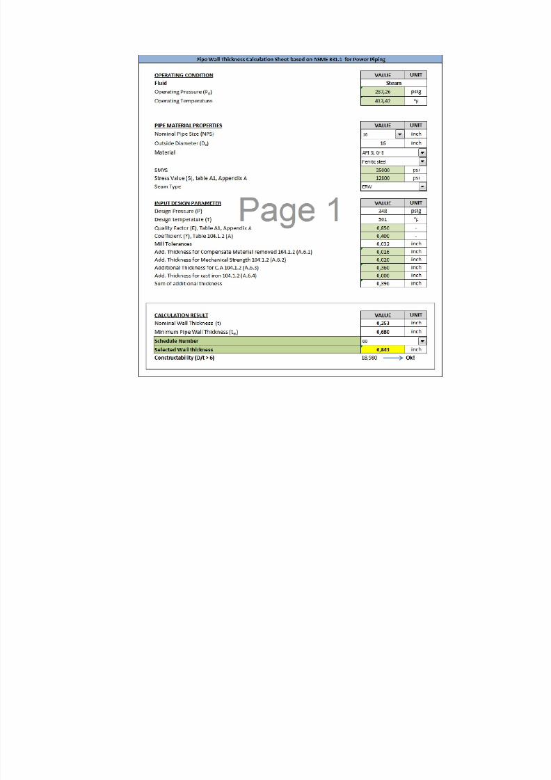
3 16"‐ST‐K84‐C1‐H 16 steam API 5L 287,26 347,59 413,42 500,24
4 24"‐ST‐K84‐B2‐H 24 steam API 5L 113,11 136,87 357,26 432,28
5 10"‐ST‐K80‐C1‐H 10 steam API 5L 287,26 347,59 415,22 502,42
6 16"‐ST‐K80‐B2‐H 16 steam API 5L 113,65 137,52 344,12 416,39
7 30"‐ST‐KWKC‐B4‐H 30 steam API 5L 109,39 132,36 355,82 430,54
8
8"‐
ST‐
K86‐
C1‐
H
8
steam API
5L 145,04 175,50 370,76
448,629 12"‐ST‐K86‐B2‐H 12 steam API 5L 113,11 136,87 357,26 432,28
10 8"‐ST‐K79‐C1‐H 8 steam API 5L 113,65 137,52 344,12 416,39
8/13/2019 Pipe Wall Thickness Calc IFA_A
http://slidepdf.com/reader/full/pipe-wall-thickness-calc-ifaa 7/32
FRONT END ENGINEERING DESIGN (FEED) MAKINGTOTAL PROJECT KAMOJANG UNIT 5 (1 x 30 MW) –
WEST JAVA
TITLE DOCUMENT NUMBER PAGE
CALCULATION OF PIPE WALLTHICKNESS
KMJ5-SG-PI-CSH-001 7 OF 32
Stream Line Number NPS
(in)
Service Material
Tekanan
Operasi
si
Tekanan
Desain
si
Temperatur
Operasi
oF
Temperatur
Desain
oF
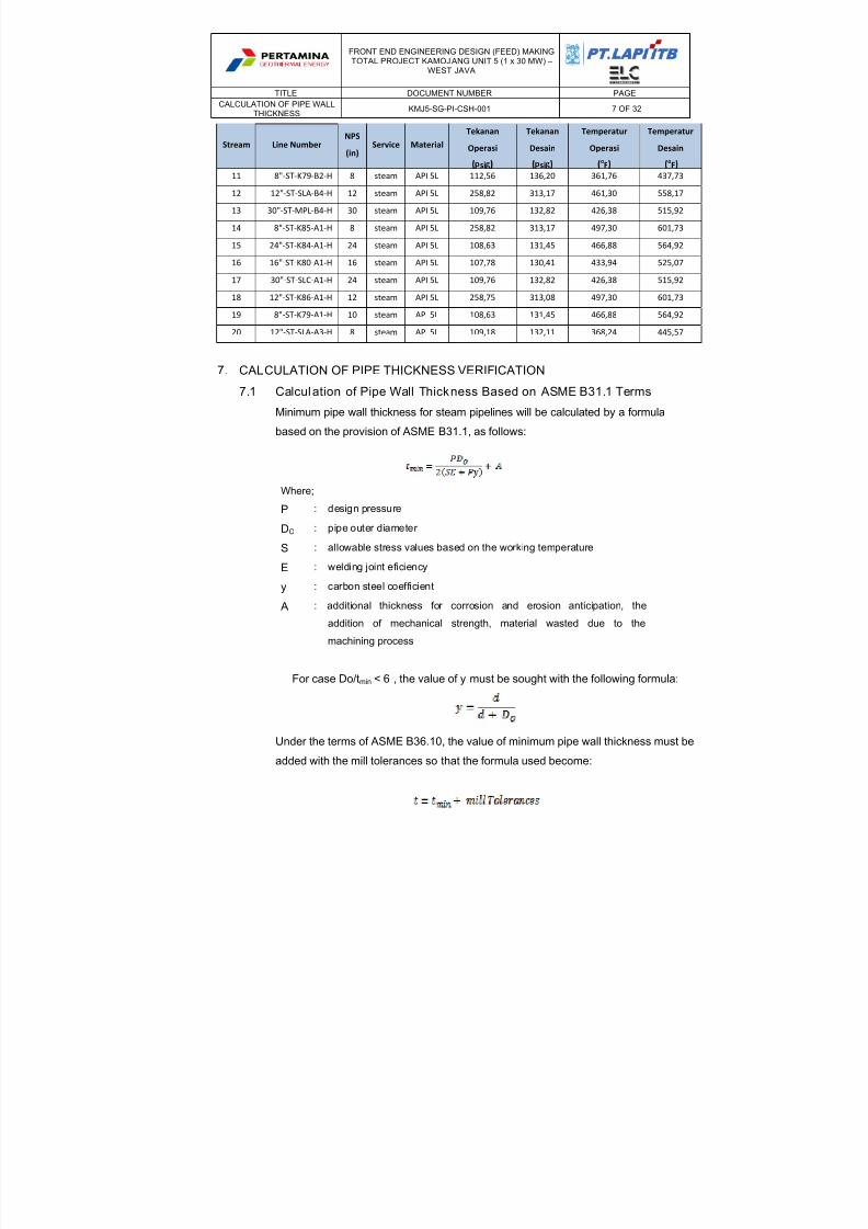
11 8"‐ST‐K79‐B2‐H 8 steam API 5L 112,56 136,20 361,76 437,73
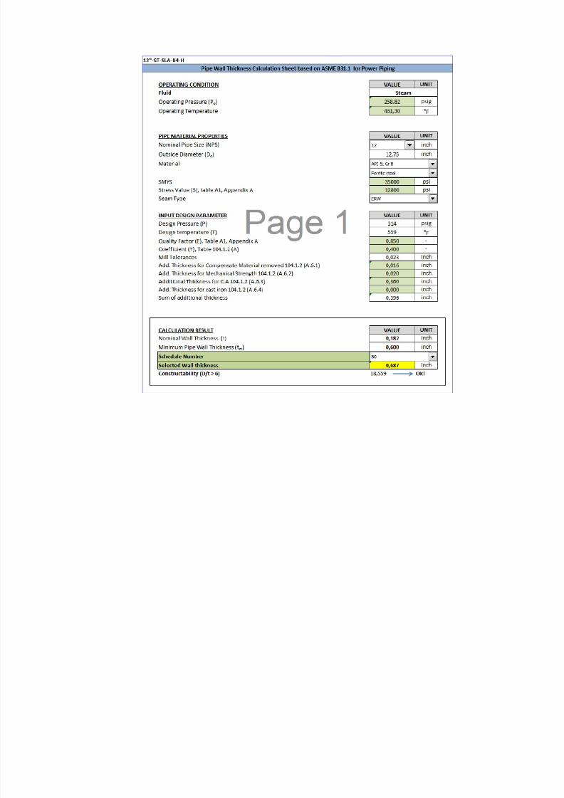
12 12"‐ST‐SLA‐B4‐H 12 steam API 5L 258,82 313,17 461,30 558,17
13 30"‐ST‐MPL‐B4‐H 30 steam API 5L 109,76 132,82 426,38 515,92
14 8"‐ST‐K85‐A1‐H 8 steam API 5L 258,82 313,17 497,30 601,73
15 24"‐ST‐K84‐A1‐H 24 steam API 5L 108,63 131,45 466,88 564,92
16 16"‐ST‐K80‐A1‐H 16 steam API 5L 107,78 130,41 433,94 525,07
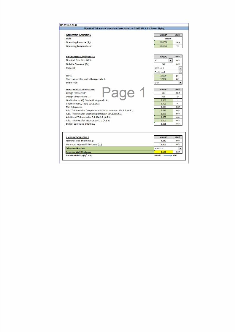
17 30"‐ST‐SLC‐A1‐H 24 steam API 5L 109,76 132,82 426,38 515,92
18 12"‐ST‐K86‐A1‐H 12 steam API 5L 258,75 313,08 497,30 601,73
19 8"‐ST‐K79‐A1‐H 10 steam API 5L 108,63 131,45 466,88 564,92
20 12"‐ST‐SLA‐A3‐H 8 steam API 5L 109,18 132,11 368,24 445,57
7. CALCULATION OF PIPE THICKNESS VERIFICATION
7.1 Calculation of Pipe Wall Thickness Based on ASME B31.1 Terms
Minimum pipe wall thickness for steam pipelines will be calculated by a formula
based on the provision of ASME B31.1, as follows:
Where;
P : design pressure
DO : pipe outer diameter
S : allowable stress values based on the working temperature
E : welding joint eficiency
y : carbon steel coefficient
A : additional thickness for corrosion and erosion anticipation, theaddition of mechanical strength, material wasted due to the
machining process
For case Do/tmin < 6 , the value of y must be sought with the following formula:
Under the terms of ASME B36.10, the value of minimum pipe wall thickness must be
added with the mill tolerances so that the formula used become:
8/13/2019 Pipe Wall Thickness Calc IFA_A
http://slidepdf.com/reader/full/pipe-wall-thickness-calc-ifaa 8/32
FRONT END ENGINEERING DESIGN (FEED) MAKINGTOTAL PROJECT KAMOJANG UNIT 5 (1 x 30 MW) –
WEST JAVA
TITLE DOCUMENT NUMBER PAGE
CALCULATION OF PIPE WALLTHICKNESS
KMJ5-SG-PI-CSH-001 8 OF 32
7.2 Minimum Thickness (Tmin) of Pipe Wall
Minimum pipe wall thickness is the thickness of the pipe requisite by ASME B31.1
by considering additional thickness because of the mechanical allowances for
anticipation and corrosion allowance, machining tolerances for the surface material
at machining and a depth threaded tolerance to the threaded pipe components.
7.3 Design Pressure (P) and Design Temperature (T)
Design pressure and design temperature that will be used for the calculation of the
pipe wall thickness is planned for 1.21 times the operating pressure and operating
temperature on each pipe that refers Design Basis and Hydraulic Analysis, Heat &
Material Balance.
7.4 Pipe Outer Diameter (Do)
Pipe outer diameter (DO) is the outer diameter of the pipe refers to the Line Sizing
document DNG-DTNK-PR-CSH-007 with a Nominal Pipe Size (NPS) obtained from
the sizing result using HYSYS software.
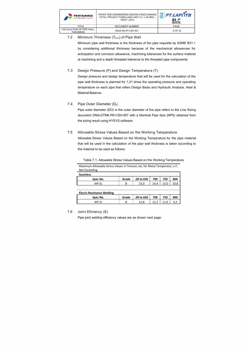
7.5 Allowable Stress Values Based on the Working Temperature
Allowable Stress Values Based on the Working Temperature for the pipe material
that will be used in the calculation of the pipe wall thickness is taken according to
the material to be used as follows:
Table 7.1. Allowable Stress Values Based on the Working Temperature.
Maximum Allowable Stress Values in Tension, ksi, for Metal Temperatur, o F,
Not Exceeding
Seamless
Spec No. Grade ‐20 to 650 700 750 800
API 5L B 15,0 14,4 13,0 10,8
Elecric Resistance Welding
Spec No. Grade ‐20 to 650 700 750 800
API 5L B 12,8 12,2 11,0 9,2
7.6 Join t Eficiency (E)
Pipe joint welding efficiency values are as shown next page:
8/13/2019 Pipe Wall Thickness Calc IFA_A
http://slidepdf.com/reader/full/pipe-wall-thickness-calc-ifaa 9/32
FRONT END ENGINEERING DESIGN (FEED) MAKINGTOTAL PROJECT KAMOJANG UNIT 5 (1 x 30 MW) –
WEST JAVA
TITLE DOCUMENT NUMBER PAGE
CALCULATION OF PIPE WALLTHICKNESS
KMJ5-SG-PI-CSH-001 9 OF 32
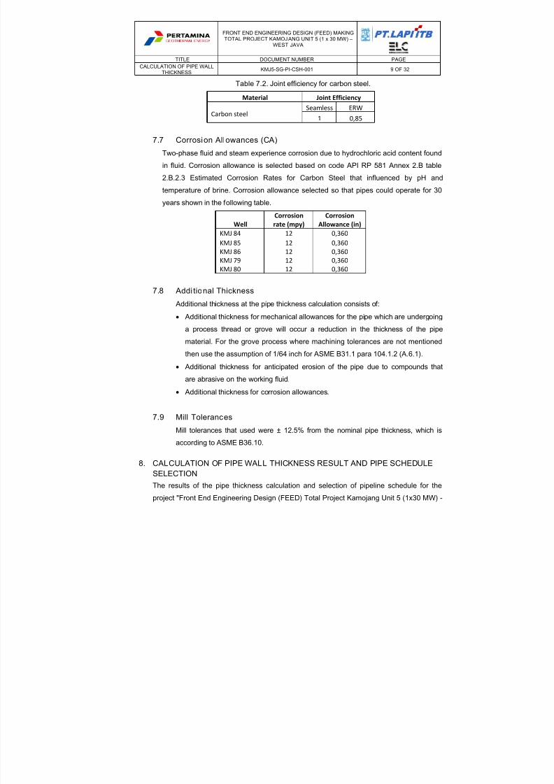
Table 7.2. Joint efficiency for carbon steel.
Material
Joint Efficiency
Carbon steel Seamless ERW
1 0,85
7.7 Corrosion Allowances (CA)
Two-phase fluid and steam experience corrosion due to hydrochloric acid content found
in fluid. Corrosion allowance is selected based on code API RP 581 Annex 2.B table
2.B.2.3 Estimated Corrosion Rates for Carbon Steel that influenced by pH and
temperature of brine. Corrosion allowance selected so that pipes could operate for 30years shown in the following table.
Well
Corrosion
rate (mpy)
Corrosion
Allowance (in)
KMJ 84 12 0,360
KMJ 85 12 0,360
KMJ 86 12 0,360
KMJ 79 12 0,360
KMJ 80 12 0,360
7.8 Addi tional Thickness
Additional thickness at the pipe thickness calculation consists of:
Additional thickness for mechanical allowances for the pipe which are undergoing
a process thread or grove will occur a reduction in the thickness of the pipe
material. For the grove process where machining tolerances are not mentioned
then use the assumption of 1/64 inch for ASME B31.1 para 104.1.2 (A.6.1).
Additional thickness for anticipated erosion of the pipe due to compounds that
are abrasive on the working fluid.
Additional thickness for corrosion allowances.
7.9 Mill Tolerances
Mill tolerances that used were ± 12.5% from the nominal pipe thickness, which is
according to ASME B36.10.
8. CALCULATION OF PIPE WALL THICKNESS RESULT AND PIPE SCHEDULE
SELECTION
The results of the pipe thickness calculation and selection of pipeline schedule for the
project "Front End Engineering Design (FEED) Total Project Kamojang Unit 5 (1x30 MW) -

8/13/2019 Pipe Wall Thickness Calc IFA_A
http://slidepdf.com/reader/full/pipe-wall-thickness-calc-ifaa 10/32
FRONT END ENGINEERING DESIGN (FEED) MAKINGTOTAL PROJECT KAMOJANG UNIT 5 (1 x 30 MW) –
WEST JAVA
TITLE DOCUMENT NUMBER PAGE
CALCULATION OF PIPE WALLTHICKNESS
KMJ5-SG-PI-CSH-001 10 OF 32
West Java" can be seen from the calculation resume table can be found in Appendix A.
Calculation sheet for calculation of pipe wall thickness can be found in Appendix B.
8/13/2019 Pipe Wall Thickness Calc IFA_A
http://slidepdf.com/reader/full/pipe-wall-thickness-calc-ifaa 11/32
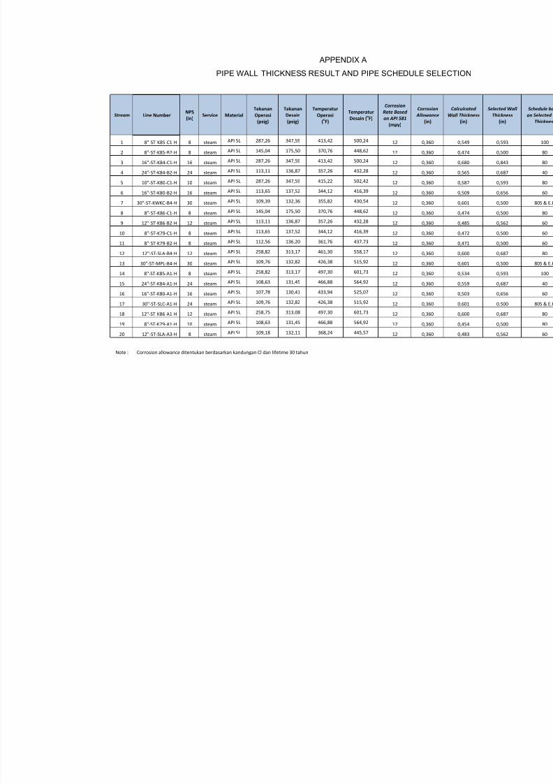
APPENDIX A
PIPE WALL THICKNESS RESULT AND PIPE SCHEDULE SELECTION
Stream Line Number NPS
(in) Service Material
Tekanan
Operasi
(psig)
Tekanan
Desain
(psig)
Temperatur
Operasi
(oF)
Temperatur
Desain (oF)
Corrosion Rate Based on API 581
(mpy)
Corrosion Allowance
(in)
Calculcat
Wall Thickn(in)
1 8"‐ST‐K85‐C1‐H 8 steam API 5L 287,26 347,59 413,42 500,24 12 0,360 0,549
2 8"‐ST‐K85‐B2‐H 8 steam API 5L 145,04 175,50 370,76 448,62 12 0,360 0,474
3 16"‐ST‐K84‐C1‐H 16 steam API 5L 287,26 347,59 413,42 500,24 12 0,360 0,680
4 24"‐ST‐K84‐B2‐H 24 steam API 5L 113,11 136,87 357,26 432,28 12 0,360 0,565
5 10"‐ST‐K80‐C1‐H 10 steam API 5L 287,26 347,59 415,22 502,42 12 0,360 0,587
6
16"‐ST
‐K80
‐B2
‐H
16
steam
API
5L
113,65
137,52
344,12
416,39
12
0,360
0,509
7 30"‐ST‐KWKC‐B4‐H 30 steam API 5L 109,39 132,36 355,82 430,54 12 0,360 0,601
8 8"‐ST‐K86‐C1‐H 8 steam API 5L 145,04 175,50 370,76 448,62 12 0,360 0,474
9 12"‐ST‐K86‐B2‐H 12 steam API 5L 113,11 136,87 357,26 432,28 12 0,360 0,485
10 8"‐ST‐K79‐C1‐H 8 steam API 5L 113,65 137,52 344,12 416,39 12 0,360 0,472
11 8"‐ST‐K79‐B2‐H 8 steam API 5L 112,56 136,20 361,76 437,73 12 0,360 0,471
12 12"‐ST‐SLA‐B4‐H 12 steam API 5L 258,82 313,17 461,30 558,17 12 0,360 0,600
13 30"‐ST‐MPL‐B4‐H 30 steam API 5L 109,76 132,82 426,38 515,92 12 0,360 0,601
14 8"‐ST‐K85‐A1‐H 8 steam API 5L 258,82 313,17 497,30 601,73 12 0,360 0,534
15 24"‐ST‐K84‐A1‐H 24 steam API 5L 108,63 131,45 466,88 564,92 12 0,360 0,559
16 16"‐ST‐K80‐A1‐H 16 steam API
5L
107,78
130,41
433,94
525,07
12 0,360 0,503
17 30"‐ST‐SLC‐A1‐H 24 steam API 5L 109,76 132,82 426,38 515,92 12 0,360 0,601
18 12"‐ST‐K86‐A1‐H 12 steam API 5L 258,75 313,08 497,30 601,73 12 0,360 0,600
19 8"‐ST‐K79‐A1‐H 10 steam API 5L 108,63 131,45 466,88 564,92 12 0,360 0,454
20 12"‐ST‐SLA‐A3‐H 8 steam API 5L 109,18 132,11 368,24 445,57 12 0,360 0,483
Note : Corrosion allowance ditentukan berdasarkan kandungan Cl dan lifetime 30 tahun
8/13/2019 Pipe Wall Thickness Calc IFA_A
http://slidepdf.com/reader/full/pipe-wall-thickness-calc-ifaa 12/32
APPENDIX B
PIPE WALL THICKNESS CALCULATION SHEET
8/13/2019 Pipe Wall Thickness Calc IFA_A
http://slidepdf.com/reader/full/pipe-wall-thickness-calc-ifaa 13/32
8/13/2019 Pipe Wall Thickness Calc IFA_A
http://slidepdf.com/reader/full/pipe-wall-thickness-calc-ifaa 14/32

8/13/2019 Pipe Wall Thickness Calc IFA_A
http://slidepdf.com/reader/full/pipe-wall-thickness-calc-ifaa 15/32

8/13/2019 Pipe Wall Thickness Calc IFA_A
http://slidepdf.com/reader/full/pipe-wall-thickness-calc-ifaa 16/32

8/13/2019 Pipe Wall Thickness Calc IFA_A
http://slidepdf.com/reader/full/pipe-wall-thickness-calc-ifaa 17/32

8/13/2019 Pipe Wall Thickness Calc IFA_A
http://slidepdf.com/reader/full/pipe-wall-thickness-calc-ifaa 18/32

8/13/2019 Pipe Wall Thickness Calc IFA_A
http://slidepdf.com/reader/full/pipe-wall-thickness-calc-ifaa 19/32

8/13/2019 Pipe Wall Thickness Calc IFA_A
http://slidepdf.com/reader/full/pipe-wall-thickness-calc-ifaa 20/32

8/13/2019 Pipe Wall Thickness Calc IFA_A
http://slidepdf.com/reader/full/pipe-wall-thickness-calc-ifaa 21/32

8/13/2019 Pipe Wall Thickness Calc IFA_A
http://slidepdf.com/reader/full/pipe-wall-thickness-calc-ifaa 22/32

8/13/2019 Pipe Wall Thickness Calc IFA_A
http://slidepdf.com/reader/full/pipe-wall-thickness-calc-ifaa 23/32
8/13/2019 Pipe Wall Thickness Calc IFA_A
http://slidepdf.com/reader/full/pipe-wall-thickness-calc-ifaa 24/32

8/13/2019 Pipe Wall Thickness Calc IFA_A
http://slidepdf.com/reader/full/pipe-wall-thickness-calc-ifaa 25/32

8/13/2019 Pipe Wall Thickness Calc IFA_A
http://slidepdf.com/reader/full/pipe-wall-thickness-calc-ifaa 26/32

8/13/2019 Pipe Wall Thickness Calc IFA_A
http://slidepdf.com/reader/full/pipe-wall-thickness-calc-ifaa 27/32

8/13/2019 Pipe Wall Thickness Calc IFA_A
http://slidepdf.com/reader/full/pipe-wall-thickness-calc-ifaa 28/32
8/13/2019 Pipe Wall Thickness Calc IFA_A
http://slidepdf.com/reader/full/pipe-wall-thickness-calc-ifaa 29/32

8/13/2019 Pipe Wall Thickness Calc IFA_A
http://slidepdf.com/reader/full/pipe-wall-thickness-calc-ifaa 30/32

8/13/2019 Pipe Wall Thickness Calc IFA_A
http://slidepdf.com/reader/full/pipe-wall-thickness-calc-ifaa 31/32

8/13/2019 Pipe Wall Thickness Calc IFA_A
http://slidepdf.com/reader/full/pipe-wall-thickness-calc-ifaa 32/32
Top Related