


Languages
Pages
Legal


HORIZONTAL – Report No. 22 (WP7 Part B)
Physical Properties
– Solidity, Thixotropic Behaviour and Piling Behaviour –
Desk Study K. Wichmann*, C. Thormählen*, E. Pasqualini**, E. Fratalocchi**, P. Battistoni**, L. Spinosa ***, E. Carniani** *Contractor: Technical University Hamburg-Harburg (TUHH), Germany; E-mail: [email protected] **Cooperation: Polytechnic University of Marche Region, Italy ***CNR c/o Commissariat for Env. Emerg. in Puglia Region, Italy
December 2003

2 HORIZONTAL – Report No. 22
Acknowledgement
This work has been carried out with financial support from the following EU Member States: UK, Germany, France, Italy, Spain, Nordic countries, Netherlands, Denmark, Austria, EU DG
XI and JRC, Ispra.

HORIZONTAL – Report No. 22 3
CONTENTS
LIST OF TABLES 6 LIST OF FIGURES 6 SUMMARY 7 1. INTRODUCTION 8 1.1 The Horizontal project 8 1.2 The Work Package 7 8 1.3 Desk studies subject 9 1.4 Evaluation of needs for control of operations and material characteristics 10 1.4.1 Evaluation of needs for control of operation 10 1.4.2 Material characteristics 11 1.4.2.1 Sewage sludge 11 1.4.2.2 Waterworks sludge 13 1.4.2.3 Bio-waste 14 1.4.2.4 Soil 16 1.5 Search for existing Standards and Methods 18 1.6 Basic informations 18 1.6.1 Solidity 18 1.6.2 Thixotropic behaviour of solid materials 20 1.6.3 Piling behaviour 21 2. EXISTING STANDARDS OR DRAFT STANDARDS 22 2.1 Flowability 22 2.2 Solidity 22 2.3 Thixotropic behaviour 23 2.4 Piling behaviour 23 3. EVALUATION OF DRAFTING A HORIZONTAL STANDARD 24 3.1 Solidity 24 3.1.1 Shearing apparatus 24 3.1.1.1 Standards analysed 24 3.1.1.2 Laboratory or field test feasibility 25 3.1.1.3 Apparatus 25 3.1.1.4 What is measured and how 25 3.1.1.5 Material to be examined 26 3.1.1.6 Feasibility of the methods to the materials for the Horizontal project 26 3.1.2 Vane testing apparatus 26 3.1.2.1 Standards and non-standardised methods analysed 26 3.1.2.2 Laboratory or field test feasibility 27 3.1.2.3 Apparatus 27 3.1.2.4 What is measured and how 29 3.1.2.5 Material to be examined 30 3.1.2.6 Feasibility of the methods to the materials for the Horizontal project 30 3.1.3 Penetrometer 30 3.1.3.1 Standards and non-standardised methods analysed 30 3.1.3.2 Laboratory or field test feasibility 33 3.1.3.3 Apparatus 33 3.1.3.4 What is measured and how 37

4 HORIZONTAL – Report No. 22
3.1.3.5 Material to be examined 38 3.1.3.6 Feasibility of the methods to the materials for the Horizontal project 39 3.2 Thixotropic behaviour of solid materials 40 3.2.1 Standards analysed 40 3.2.2 Laboratory or field test feasibility 41 3.2.3 Apparatus 41 3.2.4 What is measured and how 46 3.2.5 Material to be examined 46 3.2.6 Feasibility of the methods to the materials for the Horizontal project 46 3.3 Piling behaviour 47 3.3.1 Standards and non-standardised methods analysed 47 3.3.2 Laboratory or field test feasibility 48 3.3.3 Apparatus 48 3.3.4 What is measured and how 51 3.3.5 Material to be examined 51 3.3.6 Feasibility of the methods to the materials for the Horizontal project 51 4. CRITICAL POINT AND RECOMMENDATIONS 53 4.1 Solidity 53 4.1.1 Comparison (discussion: pro/contra) 53 4.1.2 Recommendations 56 4.1.2.1 Laboratory reference method 56 4.1.2.2 Field test 56 4.2 Thixotropic behaviour of solid materials 56 4.2.1 Comparison (discussion: pro/contra) 56 4.2.2 Recommendations 57 4.2.2.1 Laboratory reference method 57 4.2.2.2 Field test 57 4.3 Piling behaviour 57 4.3.1 Comparison (discussion: pro/contra) 57 4.3.2 Recommendation 58 4.3.2.1 Laboratory reference method 58 4.3.2.2 Field test 58 4.4 Summary of recommended methods 58 4.5 Research needs 59 4.5.1 Basics of methods 59 4.5.2 Applicability of methods to Horizontal materials 59 4.5.3 Questions to be answered 60 4.5.4 Route, how to answer them 60 4.5.5 Steps to be taken 60 4.6 Contacts with CEN/TC's/WG's 61 4.6.1 Actions 61 4.6.2 Comments received and incorporated 61 4.6.3 Official meetings 61 5. DRAFT STANDARD (CEN TEMPLATE) 62 5.1 Solidity 62 5.1.1 Laboratory reference method 62 5.1.1.1 Method 1 62 5.1.1.2 Method 2 62 5.1.1.3 Method 3 62 5.1.2 Field test 62

HORIZONTAL – Report No. 22 5
5.1.2.1 Method 1 62 5.1.2.2 Method 2 62 5.2 Thixotropic behaviour of solid materials 62 5.2.1 Laboratory reference method 62 5.2.1.1 Method 1 62 5.2.2 Field test 63 5.2.2.1 Method 1 63 5.2.2.2 Method 2 63 5.3 Piling behaviour 63 5.3.1 Laboratory reference method 63 5.3.1.1 Method 1 63 5.3.1.2 Method 2 63 5.3.2 Field test 63 5.3.2.1 Method 1 63 REFERENCES 64 ANNEX 1 68 ANNEX 2 69 ANNEX 3 70 ANNEX 4 71 ANNEX 5 72 ANNEX 6 73 ANNEX 7 74 ANNEX 8 75 ANNEX 9 76 ANNEX 10 77 ANNEX 11 78 ANNEX 12 79 ANNEX 13 80 ANNEX 14 81

6 HORIZONTAL – Report No. 22
LIST OF TABLES
Table 1: Particle size distribution of sewage sludges.................................................................. 11 Table 2: Rheological properties of sewage sludges .................................................................... 12 Table 3: Determination of the composition of sludge ................................................................. 13 Table 4: Particle size distribution of OFMSW............................................................................ 15 Table 5: Rheological properties of OFMSW aerobically or anaerobically treated ..................... 16 Table 6: Grain size of soils according to different classification systems................................... 17 Table 7: Standards for shearing apparatus................................................................................... 24 Table 8: Standards and non-standardised methods for vane testing apparatus ........................... 27 Table 9: Standards and non-standardised methods for penetrometer.......................................... 33 Table 10: Standards for thixotropic behaviour............................................................................ 41 Table 11: Standards and non-standardised methods for piling behaviour................................... 48 Table 12: Summary of the recommended apparatuses................................................................ 58
LIST OF FIGURES
Fig. 1: Collation between shearing strength and dry solid method [9]........................................ 12 Fig. 2: Comparison dry solid contents vs. laboratory vane shear strength [12] .......................... 14 Fig. 3: Schematic stress-strain curve of solid materials [28]....................................................... 19 Fig. 4: Thixotropy in viscosity-time-graph ([29] modified)........................................................ 20 Fig. 5: Thixotropy in flow curve graph and viscosity curve ([30] modified).............................. 20 Fig. 6: Test samples in single and double shear (shear box) [32] ............................................... 25 Fig. 7: Triaxial compression test showing test pressure and assumed plane of failure AB [33] . 25 Fig. 8: Vane shear apparatus and geometry of field vanes [33, 34] ............................................ 28 Fig. 9: Vane torque spring, electrical transducer details geometry and miniature vane blade
geometry [35].......................................................................................................... 28 Fig. 10: Laboratory vane shear apparatus [23]............................................................................ 29 Fig. 11: Pocket vane shear apparatus [15]................................................................................... 29 Fig. 12: Soil cone penetrometer [36]........................................................................................... 34 Fig. 13: Vicat apparatuses [37].................................................................................................... 34 Fig. 14: Apparatus for measuring consistency by penetration [38]............................................. 35 Fig. 15: Penetrometer with standard and optional penetration cone (dim. in mm) [39, 40]........ 35 Fig. 16: Magnesium penetrometer cone [41] .............................................................................. 36 Fig. 17: Pocket penetrometer after Neuschäfer [23] ................................................................... 36 Fig. 18: Pocket cylinder penetrometer [42]................................................................................. 37 Fig. 19: Consistometer (Vebe meter, dimensions in mm) [43] ................................................... 42 Fig. 20: Flow table [44]............................................................................................................... 42 Fig. 21: Flow table and conical mould (dimensions in mm) [45] ............................................... 43 Fig. 22:Vibrating table (dimensions in millimetre) [46] ............................................................. 44 Fig. 23: Compaction rig assembly with vibrating hammer (dimensions mm) [47]..................... 45 Fig. 24: Forms of slump [49]....................................................................................................... 48 Fig. 25: Compacting factor apparatus [50].................................................................................. 49 Fig. 26: Oedometer [48] .............................................................................................................. 49 Fig. 27: Device for loading [48].................................................................................................. 50 Fig. 28: Cubic Piling Box at start of test (closed sidewalls) [48]................................................ 50 Fig. 29: Cubic Piling Box at the end of test (opened sidewalls) [48].......................................... 50 Fig. 30: Relation between the parameter K and the apex angle b of the cone ............................ 54 Fig. 31: Comparison penetrometer bearing capacity vs. laboratory vane shear strength [16] .... 55

HORIZONTAL – Report No. 22 7
SUMMARY
The “Horizontal” project has the objective to develop horizontal and harmonised European standards in the fields of sludge, bio-waste and soil to facilitate regulation of these major streams in the multiple decisions related to different uses and disposal governed by EU Directives. The Horizontal Project includes the Work Package 7 “Mechanical properties” consisting in the development of Desk Studies on physical consistency, because it is recognized that this property is very important for the characterization of sludge, since it affects almost all treatment, utilization and disposal operations, such as storage, pumping, transportation, handling, land-spreading, dewatering, drying, landfilling. The importance of the physical consistency is also true for the characterization of bio-waste and soil. Also handling and utilization of many other materials, such as cement and asphalt are strictly depending on their physical consistency. The needs for control of operations and also material characteristics are described. The first action carried out is consisted in searching for existing standards to be possibly used or adapted for utilisation in the specific field of consistency evaluation. The complete list of standards is reported in Annex 1, from which it can be seen that more than 250 standards and non-standardised methods are potentially applicable to consistency evaluation. On the basis of the selected list of standards and non-standardised methods for further consideration the methods for the determination of solidity, thixotropic behaviour and piling behaviour of sludge, bio-waste and soil have been divided into several groups, according to the instruments used for measuring: • Solidity: Shearing apparatus, Vane testing apparatus and Penetrometers • Thixotropic behaviour: It should be investigated a combination of methods for determination
of the solidity like penetration, etc. and an energy-input in terms of "flow" apparatus to simulate the shear stress.
• Piling behaviour: Slump test apparatus, Compacting apparatus, Cubic Piling Box (CPB) and "Turned Box".
For each group was evaluated the laboratory or field test feasibility. Apparatuses of the measuring procedures and existing applications to different materials were described. On this basis the applicability of the described methods to the materials for the Horizontal Project was evaluated and documented in the lists of analysed standards (Chapter 3). The recommended methods are for solidity the “Laboratory vane shear apparatus” and “Vicat needle” as laboratory reference and the pocket penetrometers for field test. The penetrometers in general could be used for both laboratory reference method and field test. Also for determination of the thixotropic behaviour the penetrometer is together with an energy-input in terms of a vibrating table or a hammer a suitable instrument. For measuring the piling behaviour the Cubic Piling Box (CPB) and the Oedometer are the recommended methods, whereby the CPB could be used in both laboratory and field while the Oedometer could be used only in the laboratory. For the research needs first the basics of methods are explicated. Also the applicability of methods to Horizontal materials is clarified. The questions to be answered (precision, repeatability, reliability, etc.), the route, how to answer them and finally the steps to be taken are important for following procedures within the Horizontal project. The results of the circulation within the consulting CEN/TC's/WG's/TG’s – Committee's are documented by means of listed actions, comments, which were received, and official meetings, which amount up to four WP7 meetings and two CEN/TC308/WG1 and CEN/TC308/WG1/TG3 meetings each so far. In the Horizontal-Report No. 22 a total of 11 proposals for draft standards are given, consisting of six laboratory methods and five field tests.

8 HORIZONTAL – Report No. 22
1. INTRODUCTION
1.1 The Horizontal project The revision of the Sewage Sludge Directive 86/278/EEC, the upcoming Composting Directive on the biological treatment of biodegradable waste and the Soil Monitoring Directive call for standards on sampling, hygienic and biological parameters, methods for inorganic and organic contaminants, and for mechanical properties of these materials. In addition, when materials cannot be utilized, landfilling becomes important, in which case leaching becomes an issue as stipulated by the Council Directive 1999/31/EC on the landfill of waste. More recently, a Council Decision establishing criteria and procedures for the acceptance of waste at landfills, pursuant to Article 16 and Annex II of mentioned Directive on the landfill of waste was issued (16/12/02) with physical consistency being one basic parameter of interest. The “Horizontal” project has the objective to develop horizontal and harmonised European standards in the fields of sludge, bio-waste and soil to facilitate regulation of these major streams in the multiple decisions related to different uses and disposal governed by EU Directives. Part of the work to be carried out will focus on co-normative work with an emphasis on horizontal standardization starting from existing standards developed for the same parameter in the fields of sludge, bio-waste and soil. Another part of the work will focus on pre-normative research required to develop standards lacking at this point and needed in the next revision of the regulations in these fields.
1.2 The Work Package 7 The Horizontal Project includes the Work Package 7 “Mechanical properties” consisting in the development of Desk Studies on physical consistency, because it is recognized that this property is very important for the characterization of sludge e.g., since it affects almost all treatment, utilization and disposal operations, such as storage, pumping, transportation, handling, land-spreading, dewatering, drying, landfilling. In fact, the selection of the most suitable equipment and procedure for land application, storage and transportation of sludge e.g. is strongly connected to its consistency. Similarly, compacting sludge in a landfill or forming a pile in composting is depending on sludge shear strength rather than on its solids concentration. In particular, with reference to the regulations requirements, according to the Sludge Directive 278/86, agricultural reused sludge must have agronomic interest, be healthy and easily usable, i.e. easily stored, transported, handled, and spread. In Council Directive 1999/31/EC (Landfill Directive), Article 2 (q) gives a definition of “liquid waste”, and Article 5 (3.a) does not allow a liquid waste to be landfilled, but a standardized method for this evaluation has to be developed yet. Further, Annex II (2. General principles) requires that “The composition, ... and general properties of a waste to be landfilled must be known as precisely as possible”, and Annex I (6. Stability) is referring to “... ensure stability of the mass of waste ... particularly in respect of avoidance of slippage”, so the shear strength and piling behaviour must be known. Article 2 (h) says, that “treatment means ... processes ... in order to … facilitate its handling”. Finally, Article 11 (1.b) asks for: “ – visual inspection of the waste at the entrance and at the point of deposit and, as appropriate, verification of conformity with the description provided in the document submitted by the holder”, so simple and easy tests to be carried out on the field and followed by the operators must be defined. Further, the Council Directive establishing criteria and procedures for the acceptance of waste at landfills, pursuant to Article 16 and Annex II of mentioned Directive on waste landfilling included “consistency” among the basic parameters to be evaluated for waste characterization before landfilling; for specific cases it is also demanded, that EU Member States must set criteria to ensure a sufficient physical stability and bearing capacity of waste.

HORIZONTAL – Report No. 22 9
It is also to be pointed out that in many analytical methods for sludge characterization (e.g. pH, dry matter, leachability, etc.) different procedures are indicated depending on whether the sample to be examined is liquid or not, is solid or not, but no procedures are given for evaluating such properties. The importance of the physical consistency is also true for the characterization of bio-waste and soil. For WP7 two desk studies were performed: No. 21 for the parameter "Flowability" and No. 22 for the parameters "Solidity", "Thixotropic Behaviour" and "Piling Behaviour". The work was coordinated in WP7 and done in cooperation of the involved teams. Therefore the reports No. 21 and No. 22 contain some chapters (1.1 – 1.5 and 2) and the list of standards and non-standardised methods (Annex 1) in common.
1.3 Desk studies subject The Task Group 3 (TG3) of CEN/TC308/WG1 defined 3 physical states for sludge (CEN/TC308/WG1/TG3, 2000):
a) Liquid: sludge flowing under the effect of gravity or pressure below a certain threshold. b) Paste-like: sludge capable of continuous flow under the effect of pressure above a certain
threshold and having a shear resistance below a certain threshold. c) Solid: sludge having a shear resistance above a certain threshold. This firstly involves the necessity to set up methods to measure values in the range of the boundary area between liquid and paste-like behaviours (limit of flowability) and that between solid and paste-like (limit of solidity). Further, the thixotropic behaviour of solid materials (from “the solid to the liquid state and vice versa”) must be evaluated, together with the piling behaviour referred both to “compaction and physical stability”. Also the CEN/TC292/WG2, in the method prEN 12457 for the characterisation of waste included in Annex B (Informative) the description of a test for determining whether waste is in the liquid state (CEN/TC292/WG2, 2002). Although the methods to be developed are partly known and used in other technology fields, e.g. soil mechanics, materials for construction works (concrete, suspensions), etc., widely accepted methodologies for the evaluation of above properties, able to give comparable and reliable results, are not available yet. It therefore follows the necessity to define simple and reliable measurement procedures to be applied in the field, together with those to be used as reference in laboratory. Standardisation procedures for Horizontal material examination will consist of - Sampling, transport, preservation, storage - Pre-treatment - Measurement and evaluation of results.

10 HORIZONTAL – Report No. 22
1.4 Evaluation of needs for control of operations and material characteristics
1.4.1 Evaluation of needs for control of operation The purpose of using characterisation standards is to control and ascertain the material amenability to handling and different operations. Materials considered are - Sewage sludge - Waterworks sludge - Bio-waste and - Soil. Materials, which cannot be utilised, are subjected as waste to the Landfill Directive (Council Directive 1999/31/EC), resp. the ordinances of the member states. The member states had to translate this directive into national law. In Germany e.g., there is the landfill ordinance, which became operative on 10.07.2002. Furthermore there does exist the waste disposal ordinance, it is a kind of adjustment resp. update of the German “TA Siedlungsabfall”. By this regulation among other things the limit value of ≥ 25 kN/m² for vane shear strength – termed here in the HORIZONTAL Report - was set. For this regulation it is not important, from where the materials come from. It is valid for different resp. all kinds of wastes: bio-waste, solidified wastes, soils, etc. For handling and operating these materials many parameters should have to be known; they include homogeneity, particles sizes and shape, solids (total, suspended, volatile) that, if available, could define the range of variation of variable considerations (i.e. viscosity, etc.). The parameters flowability is an overall parameter taking into account all above mentioned material properties or characteristics. In particular, the flowability evaluation for sludges, including wastewater, waterworks and similar sludges, is of fundamental importance in many operations such as pumping, transportation, storage, dewatering, stabilisation, spreading, etc. also considering the possible formation from a gel to a liquid (sol) and vice versa. Similarly, for bio-waste, including the shredded organic fraction of municipal solid waste (OFMSW), in operations such as handling, digestion, reuse, etc. the measure of the parameter flowability have to be considered. Finally, for fine-grained soils, the water content (and therefore consistency and flowability) has always been considered an important indication of their mechanical properties. Moreover in case of soil slurries it is very important to verify flowability as a measurement of their workability and time of setting. The solidity is also a parameter, which concerns all the material properties or characteristics mentioned above. The determination of this parameter is getting more important for handling of solid materials like dewatered sludge, other bio-waste – e.g. in terms of pieces (compost) – and soil, where the grain size distribution and water content have to be considered, during operations like pumping, transportation, storage, etc. The measurement of thixotropic behaviour for solid materials is especially for dewatered sludges like sewage, waterworks and related sludges relevant. By dewatering and storage the sludge will become solid. During operations such as transportation the sludge is getting due to the vibration of e.g. a truck in a liquid state. The piling behaviour evaluation is for dewatered sludge, particular bio-waste and soil of importance. The determination of the piling angle is a useful instrument to characterise the storage properties and calculate the space, which is needed for e.g. storage and transportation of the above materials. Together with the thixotropic behaviour the piling behaviour refers to the compaction and stability.

HORIZONTAL – Report No. 22 11
However, the development of reliable measurement procedures of all parameters is not a simple matter, because measurements are influenced by below described properties or characteristics. This means that those factors must be considered with great attention and methods defined by avoiding any negative interference with them during measuring procedures. For this reason, it is first necessary to select, if any, the most adapted standards or non-standardised methods applicable to sludge, bio-waste and soil, or to develop a new one, and then to carry out parallel tests to evaluate how they are affected by the other specific characteristics. In addition, these aspects require to be investigated for both laboratory methods, to be adopted as a reference, and simple tests to be applied in the field.
1.4.2 Material characteristics
1.4.2.1 Sewage sludge Sewage sludge can be produced from several processes (primary sedimentation, activated sludge process, aerobic or anaerobic digestion etc.). Their solid content cover a wide range from 1 to 30%, while different total volatile solids percentage on dry matter can vary from 75% to 45%. The presence of coarse particles is strongly related to the sieve adopted in head-works or external material used in some processes (anaerobic co-digestion, etc.). Sewage sludge covers a wide range of physical state from liquid to solid. Bibliography does not offer a characterization of particle size distribution of sewage sludge, a wide range of these characteristics is forecasting in relation to the process adopted (opening of sieves etc.) and different type of sewage sludge treated. Some indications are found for sewage sludges (see Table 1 [1]).
TS basis
% cumulative retained w.w.
TVS basis
% cumulative retained w.w.
Material
Process
5 mm 2 mm 0.84 mm 5 mm 2 mm 0.84 mm
Sewage sludges
WTS
Aerobic
process
0
3,7
9,4
0
4,7
8,4
Mixed primary
sludges
ADS
Mesophilic
anaerobic
digestion
0 10,5 18,5 0 15,5 30,5
Table 1: Particle size distribution of sewage sludges
Each kind of sludge was analysed for its particle size distribution by wet sieving, using three sieves with openings of 5,2 and 0.82 mm. According to these data the samples can be divided into four conventional classes: coarse (>5 mm), medium (from 5 to 2 mm), medium-fine (from 2 mm to 0.84 mm) and fine (<0.84 mm). It can be noted that the sewage sludges have no coarse particles but a different percentage of medium and fine particles. The most diffuse sludge characterization is that rheological, beside CST – capillary suction time, R specific resistance to filtration etc.. Rheological parameters (yield stress, viscosity and thixotropy) were originally applied to calculation of the head losses in sludge pumping operations, recently it has been shown that they can affect filtration, thickening [2], pumping [3, 4] and constitute useful on line control parameters for sludge conditioning and dewatering [5, 6, 7]. Rheological measurements of sewage sludges have been performed using commercial rotational viscometer. The rheological properties normally determined by using the Bingham plastic model are the yield stress (YS) (that is the stress required to start the material flowing) the

12 HORIZONTAL – Report No. 22
plastic viscosity (that is the internal resistance to flow under defined shear rate). The Thixotropy, determined by the hysteresis area, is only sometimes observed (Table 2) [8].
Sludge Process TS range TVS/TS YS Plastic viscosity
% Pa mPa*s
Mixed 3.0-14 0.52 1.90-185 30-630
Primary 7.0-16 0.43 1.0-49 20-320
Activated 3.0-9 0,73 5.0-214 70-1110
Mixed Sludges Aerobically
stabilized
4.0-10 0.53 0.07-58 10-410
Mixed Sludges Anaerobically
digested
4.0-9 0.59 1.0-112 20-390
Mixed sludges Mesophilic
anaerobic
digestion
3.5-5.0 0.5-0.6 0.4-1.6 8.0-24
Mixed sludges Thermophilic
anaerobic
digestion
3.5-5.0 0.5-0.6 0.1-0.5 11.0-17
Table 2: Rheological properties of sewage sludges
Mechanical properties of sewage sludge in solid state were studied with the aim to define the feasibility of landfill disposal; a correlation between shear strength and dry solid matter for sewage sludge was done using a Vane apparatus (Fig. 1) [9], sludges are suitable for landfilling if their shear strength is of 10 kN/m² at least (limit value in Italy).
Fig. 1: Collation between shearing strength and dry solid method [9]

HORIZONTAL – Report No. 22 13
1.4.2.2 Waterworks sludge In DVGW W221-1 [10] sludges are defined as solid-water suspensions capable of flowing after sedimentation, flotation or thickening. Dewatered sludges are sludges, which were dewatered by natural or mechanical treatments until they are no longer able to flow. Sludges from water treatment contain several phases differing by their physical state and/or chemical nature. The space distribution of these phases, as well as the physical-chemical interactions between them, gives to sludges their cohesion. A too low cohesion of sludges and/or its high fluctuation in the time commonly generates handling (shovelling- and spreading- ability) and storing difficulties. An orderly utilisation and disposal of waterworks sludges need the control of the mechanical properties in order to ensure a quality that is demanded for storage, transport and handling. The mechanical measurements are to be seen and done in connection with other measurements that have been or will be standardised. There are to be mentioned methods for chemical and physical parameters (chemical elements, dry solids, loss on ignition, pH-value) and operational methods (capillary suction time CST, specific filtration resistance). The different composition of waterworks sludges with inorganic (Fe, Ca, Al etc.) and organic (Algae, humid substances, powdered activated carbon etc.) substances depending on the source of raw water and water treatment processes must be considered. An inquiry from Wichmann et al (2002) [17] showed, that the waterworks sludges of different types in Germany amounted in 1998 to ca. 181.000 t DS (Lime sludge 40%, Iron sludge 14%, Fe-/Al-Flocculation sludge 13% and other 33%). The composition of the sludge can be determined after [11] (10 parameters) in Table 3.
Parameter Fraction [g/kg DS](Fictive value)
Conversion in: Fraction [g/kg DS]
Acid insoluble (= HClins.)
40 Insoluble components (e.g. sand, activated carbon)
40
TOC 30 Total organ. content (Factor: 2)
60
Mn 20 MnO2 (Factor: 1.58)
31.6
Mg 5 Mn(OH)2 (Factor: 2.,4)
12.0
Al 20 Al2O3 x H2O (Factor: 2.22)
44.4
SO4 5 CaSO4 (Factor: 1.42)
7.1 (Ca: 2.1)
CO3 (= TIC) 80 CaSO3 (Factor: 1.67)
138.6 (Ca: 57.6)
Ca –total- 65 - Residual-Ca 5.3 Ca3(PO4)2
(Factor: 2.58) 13.7
(PO4: 8.4) PO4 –total- 10 -
Residual-PO4 1.6 Fe(PO4) (Factor: 1.59)
2.5 (Fe: 0.94)
Fe –total- 415,7 - Residual-Fe 414.8 Fe2O3 x 1,5 H2O
(Factor: 1.67) 692.6
Total 1042.5 Table 3: Determination of the composition of sludge

14 HORIZONTAL – Report No. 22
The range of 0.2 to 80 % dry solids contents of waterworks sludges to be utilized is quiet wide, so that several different mechanical properties have to be measured. Possible measuring methods are coming mainly from the soil mechanical or rheological working fields. There are only few data on mechanical properties of waterworks sludges published. In Fig. 2 after Mc Tigue et al. (1990) [12] e.g. the result of 72 measurement data of different waterworks sludge types and dewatering processes are shown. A laboratory vane shear apparatus was used. The vertical line marks the dry solids concentration of 35 % that was given from LAGA (1979) [13] as a minimum value for disposal of wastes in landfills. Sludges with more than 35 % DS were than be considered to be qualified for landfilling. The horizontal line marks the minimum value of 25 kN/m2 for the vane shear strength that is now demanded from new regulations in the TA Siedlungsabfall (1993) [14]. Approximately 90 % of the waterworks sludges tested after mechanical dewatering could not fulfil the required minimum value.
Fig. 2: Comparison dry solid contents vs. laboratory vane shear strength [12]
1.4.2.3 Bio-waste Organic fraction of municipal solid waste (OFMSW) is utilized for anaerobic and composting treatment. Anaerobic digestion or co-digestion with sewage sludges is a well-known process where rheological parameters have been studied to control process.
TS basis
% cumulative retained w.w.
TVS basis
% cumulative retained w.w.
Material
Process
5 mm 2 mm 0.84 mm 5 mm 2 mm 0.84 mm
Fresh mechanically
sorted (F) OFMSW
Mesophilic
anaerobic
digestion
8,2 11,1 18,3 6,7 21 23,5
Pre-composted
mechanically sorted
( ) O S
Mesophilic
anaerobic
di i
19,7 26,1
0
5
10
15
20
25
30
35
40
0 5 10 15 20 25 30 35 40 45 50 55 60Dry Solid [% w/w]
Vane
She
ar S
treng
th [k
N/m
2 ]

HORIZONTAL – Report No. 22 15
(P) OFMSW digestion
Blend of source
sorted and
mechanically sorted
OFMSW
Mesophilic
anaerobic
digestion
6,6 11,5 18,3 12,7 16,8 24,2
Table 4: Particle size distribution of OFMSW
The OFMSW was analysed for its particle size distribution by wet sieving, using three sieves with openings of 5, 2 and 0.82 mm. According to these data the samples can be divided into four conventional classes: coarse (>5 mm), medium (from 5 to 2 mm), medium-fine (from 2 mm to 0.84 mm) and fine (<0.84 mm). The fresh mechanical sorted OFMSW show up to 18 and 24% of particles greater than fines for TS and TVS, respectively. The coarse particles are mainly extraneous materials (plastics, baggage, etc.), which have no influence on digester fluid-dynamic [21, 22].
Rheological measurements of OFMSW aerobically and anaerobically treated have been performed using commercial rotational viscometer. The rheological properties normally determined by using the Bingham plastic model are the yield stress (YS) (that is the stress required to start the material flowing) the plastic viscosity (that is the internal resistance to flow under defined shear rate). The Thixotropy, determined by the hysteresis area, is only sometimes observed (Table 5) [21, 22].
Sludge Process TS range TVS/TS YS Plastic
viscosity
Thixo-
tropy
% Pa mPa.s Pa/s
OFMSW
mechanically
sorted and pre-
composted
Thermophilic
anaerobic digestion
4.8-32.7 0.43-0.49 0.4-63 9-840
Fresh OFMSW
mechanically
sorted
Thermophilic
anaerobic digestion
6.8-25.2 0.47-0.50 0.1-102 17-1660
OFMSW
mechanically
sorted enriched
with source
sorted fraction
Thermophilic
anaerobic digestion
5.8-35.1 0.46-0.56 0.2-61 6-560
OFMSW Anaerobically
digested under
mesophilic and
4.4-18 0.52 0.25-1.2 8.0-54 12-125

16 HORIZONTAL – Report No. 22
semi-dry conditions
OFMSW Anaerobically
digested under
thermophilic and
semi-dry conditions
5.0-32.7 0.48 0.26-37.7 10-420 36-161
Table 5: Rheological properties of OFMSW aerobically or anaerobically treated
Bio-waste includes also compost, which is derived from aerobic decomposition of recycled plant waste, bio-solids, fish or other organic material. It is a mixture of decaying organic matter, as from leaves and manure, used to improve soil structure and provide nutrients. The sizes of compost pieces can vary within a wide range according to the type of compost e.g. organic municipal waste. From there the sampling and especially the pre-treatment are of great importance. For reliable measurements the grain size has to be uniform. If needed, the material has to be also compacted in order to avoid voids of higher dimensions, which could influence the results.
1.4.2.4 Soil Soils are particulate systems and can cover a wide range of physical state from liquid to solid, depending mainly on the size and mineralogy of the particles and on the water content. In particular, soils are divided into coarse-grained soils and fine-grained soils. The surface of the particles has a negative electrical charge, whose intensity depends on the soil mineral. These surface forces exist in addition to the volume forces of the particles and in fine-grained soils they play a dominant role in the mechanical and rheological behaviour. The surface forces strongly depend on the water content and more in general on the chemical composition of the interstitial fluid. For this reason, it is very important to set up standards that can define different physical states considering not only the water content but also the chemical composition of the pore fluid. The classification of a granular soil is completely defined by the grain distribution curve, the shape of particle and its specific volume. Whereas the procedure for particle size analysis is well defined and easy to perform (by a simple sieve analysis), a procedure for characterising the particle shape is not available and it should be defined as the particle shape strongly influence the mechanical behaviour of these type of soils. The behaviour of cohesive soils depends on its mineral composition, the water content, the degree of saturation and its structure. A fine-grained soil can be in a liquid, plastic, semi-solid or solid state, depending on its water content and this physical state is called consistency. The upper and lower limits of water content within which a clay element exhibits plastic behaviour are defined as liquid limit and plastic limit. The procedure is standardised (ASTM D4318) but it is recognised to be strongly affected by the operator experience. Typical values of liquid limit for natural fine-grained soils range from 40% up to 90% of water content and the plastic limit from 10%-50%. Many correlations have been proposed relating the mechanical characteristics of cohesive soils and the consistency limit; each of them is valid for the specific type of soil for which it was verified. Table 6 gives an overview of several grain distributions of different standards. The last one (British Standard) is also valid for Germany e.g. and other European countries.

HORIZONTAL – Report No. 22 17
Table 6: Grain size of soils according to different classification systems

18 HORIZONTAL – Report No. 22
1.5 Search for existing Standards and Methods The first action carried out is consisted in searching for existing standards and non-standardised methods to be possibly used or adapted for utilisation in the specific field of consistency evaluation. To this purpose, the following standardisation organisations were contacted:
• ISO at www.iso.ch
• ASTM at www.astm.org
• CEN at www.cenorm.be
• UNI at www.uni.com
• DIN at www.beuth.de
• AFNOR at www.afnor.fr/portail.asp
• BSI at www.bsi.org.uk
• ASAE at http://webstore.ansi.org/ansidocstore/default.asp
Other information was obtained through personal contacts with experts in the field. In addition, to obtain selected information, the following keywords were used for research in each web site (among other things): consistency, viscosity, flowability, shearing, sludge, soil, physical properties, flow properties, suspensions, and compactibility. The different materials resulted from the research were resins, plastic, lubricant, cement, asphalts/bitumen, etc. The complete list of standards is reported in Annex 1, from which it can be seen that more than 250 standards and non-standardised methods are potentially applicable to consistency evaluation.
1.6 Basic informations
1.6.1 Solidity Solidity is the state in which a substance has no tendency to flow under moderate stress, resists forces (such as compression) that tend to deform it, and retains a definite size and shape. It describes the consistency of a solid resp. the limit solid/ paste-like. For determination of solidity besides the resistance to pressure, the flexural resistance and tensile strength the “undrained shear strength cu” (compare Eq. 2) is an important parameter. Shear may be defined as the tendency of one part of e.g. a soil mass to slide with respect to the other. This tendency occurs on all planes throughout the soil mass. The singular plane of interest, however, is the plane of potential failure, called the plane of rupture. Shear strength, as measured along this plane of interest, is the ability of the mass to resist the occurrence of a shear failure between the soil above and below the plane. Masses, e.g. soils have the ability to develop strength in shear. Different material groups develop this strength in different ways. Generally the cohesion (c), as defined by the Geotechnics, has to be determined on basis of the evolution of the shear strength (τ) as a function of the applied axial strength (σ) using the Coulomb rule:
tancτ σ ϕ= + ⋅ (Eq. 1)

HORIZONTAL – Report No. 22 19
where ϕ is the angle of shearing resistance or friction angle. For sludges it has been observed that ϕ is near zero (Costet and Sanglerat, 1975 [24]). For this reason it is reasonable to equal τ and c (see Eq. 2). Furthermore, several authors (Gazbar, 1993 [25]; Tisot et al., 1997 [26]) considered that the yield stress (the stress above which the sludge is deformed) is equal to τ .
f ucτ = (Eq. 2)
where uc is the undrained cohesion or the undrained shear strength. The ability of a mass to support vertical loads and to resist the sliding effect of lateral loads is governed to a large extent by the shear strength of the material. It is therefore important to determinate accurately the shear strength of mass situated beneath and in close proximity to the proposed construction. There are several field and laboratory tests by which shear strength can be determined with reasonable accuracy: Triaxial compression tests, vane shear tests or direct shear tests. Besides the determination of the “bearing capacity” the “unconfined compression strength", which is determined as twice the undrained shear strength (Eq. 3), and the "California bearing ratio" are important parameters.
2u uq c= ⋅ (Eq. 3) Penetration apparatuses are also being suitable for measuring the consistency resp. shearing strength, which is determined in this case with the aid of a constant depending on the dimensions of the cone tip (see chapter 4.1.1, Eq. 7). In general the tension or compression tests consist in measuring the strain in relationship to the applied stress. From a conventional stress-strain curve (Fig. 3) it can be identify four different ways, in which the material behaves, depending on the induced strain [27]:
- Elastic behaviour: when the load acting on the material is removed, the sample returns to its original shape, (the stress is proportional to the strain),
- Yielding: a slight increase in stress above the elastic limit induces a breakdown of the material and cause it to deform permanently,
- Strain hardening: while the material is sheared, the deformation is permanent and there is no proportionality between the stress and the stress,
- Necking: a crack occurs in a localized region. Fig. 3: Schematic stress-strain curve of solid materials [28]

20 HORIZONTAL – Report No. 22
1.6.2 Thixotropic behaviour of solid materials Thixotropy or thixotropic behaviour is available, when the viscosity of a substance (shear rate γ! = const.) decreases with the time, but after a defined period of rest the initial value of the viscosity is reached again (Fig. 4, [29]). The reasons for this behaviour are special formed chem./phys. bonding forces, which influence the relocatability against each other of those components and which are destroyed by the shear strain and during the non-operated time are complete reversible regenerated. Distinctive thixotropic properties are founded e.g. for solid materials with polar surface in covalent matters.
Fig. 4: Thixotropy in viscosity-time-graph ([29] modified)
Fig. 5: Thixotropy in flow curve graph and viscosity curve ([30] modified) If the increasing curve in the flow curve graph (Fig. 5, left, I) is located above the decreasing curve (II), this behaviour is called thixotropic. The received Hysteresis area is a degree of intensity of the constructiveness forces (e.g. structure of gel). In general this area is termed "A" and has the unit "power" related to the sheared volume. If the power is multiplied by the shear time (I+II) the "work" is resulted, which is necessary in order to destroy the thixotropic structure of the bonding forces in the substance volume [30]:

HORIZONTAL – Report No. 22 21
A = τ ⋅ γ! 1Pas
⋅
2 3
N 1 N m 1Am s s m
⋅= ⋅ = ⋅
work 1 powerA
sheartime volume volume= ⋅ =
Beside the time-depended reduction of the viscosity (with a constant shear rate) there does exit a decrease of viscosity due to intensity of the shear rate (Fig. 5, right). If a material is anti-thixotropic, the position of the increasing curve in the flow curve graph is below the decreasing curve. This aspect is called "rheopexy" or also negative thixotropy. In practise it means the material is getting solid during the time of shear stress [29]. However, in this report only materials with a thixotropic behaviour are considered. In particular the value “shear strength”, which is mostly determined for the parameter “solidity”, is observed, whether it falls below the given threshold - because of shear stress - or not. Also waterwork and sewage sludges often show thixotropic behaviour. During shear stress the sludges change from the solid to the liquid state, which may hinder the utilization of the sludges during transport and handling. It must be ensured that dewatered sludges are not fluidized during transport and handling. Therefore it must be measured whether the material is behaving thixotropic and if so under which conditions.
1.6.3 Piling behaviour The materials of interest (sludge, bio-waste and soil) usually have to be stored during transportation or storage in e.g. piles or containers. To avoid problems with succeeding handling operations the pieces of these materials should undergo no major changes in form and consistence. From there it is of great importance to investigate the piling behaviour, which is displayed by the Horizontal materials. The "compactibility" or "compressibility" is a first supporting parameter for determination of the piling behaviour. These parameters could give informations about how much a stratum of piled material can settle due to the loading of the material placed above. The measurement of the "piling angle (angle of rest)" or "slope angle" is also a very helpful parameter to determinate the piling behaviour [48]. It is a new method, which is still in a development stage, but due to the easy measurement procedure and variability (compare chapter 3.3 et seq.) a promising tool for the investigation of all materials of interest. The instrument for measuring these parameters consists of a simple box with turnable sidewalls. After filling the box - where necessary compacting the material – and the sidewalls were turned over, the natural slope angle of the remaining material can be measured on each side of the sample remaining on the box base. Because of the average of four values the result are mostly reliable. A further important aspect is that the friction between the sidewalls and the material to be tested does not affect the final result.

22 HORIZONTAL – Report No. 22
2. EXISTING STANDARDS OR DRAFT STANDARDS
The research of existing and draft standards to be utilized as laboratory and field methods for Horizontal standardization has been carried out in cooperation of the teams involved in WP7 by consulting the web sites of standardization boards (cp. section 1.5). Besides these standards some non-standardised methods, which are also used in practice, were acquired. The keywords used for the research have included the possible field and relevant properties for which the standards may be applicable. The expert's of WP7 has submitted titles to a preliminary examination and the selected standards (considered for further discussion) have been acquired. They can be divided generally in to four parameter groups: flowability, solidity, thixotropic behaviour and piling behaviour.
2.1 Flowability Keywords beside the item flowability:
! Bitumen ! Cement/concrete ! Consistency ! Plasticity ! Plastics ! Sludge (sewage) ! Soil ! Slurry ! Thixotropy ! Viscosity ! Waste
In this group 129 standards and non-standardised methods have been found and 90 standards and non-standardised methods have been considered for further discussion.
2.2 Solidity Keywords beside the item solidity:
! Cement ! Concrete ! Cone ! Consistency ! Mechanical properties ! Needle ! Penetrometer ! Plasticity ! Road materials ! Shearing strength ! Sludge (sewage) ! Soil ! Soil properties ! Vane ! Waste (solid)
In this group 68 standards and non-standardised methods have been found and 32 standards and non-standardised methods have been considered for further discussion.

HORIZONTAL – Report No. 22 23
2.3 Thixotropic behaviour Keywords beside the item thixotropic behaviour:
! Cementitious & concrete materials ! Concrete ! Consistency ! Fluidity ! Penetration ball ! Road material ! Sludge (sewage)
In this group 15 standards have been found and 9 standards have been considered for further discussion.
2.4 Piling behaviour Keywords beside the item piling behaviour:
! Cement ! Cementitious & concrete materials ! Concrete ! Consistency ! Flowability ! Oedometer ! Piling box ! Plasticity ! Soil ! Waste (solid)
In this group 13 standards and non-standardised methods have been found and 8 standards and non-standardised methods have been considered for further discussion. The list of the collected titles is reported in Annex 1. The list of standards considered for further discussion is presented in chapter 3.
24 HORIZONTAL – Report No. 22
3. EVALUATION OF DRAFTING A HORIZONTAL STANDARD
On the basis of the selected list of standards and non-standardised methods for further consideration the methods for the determination of solidity, thixotropic behaviour and piling behaviour of sludge, bio-waste and soil have been divided into several groups, according to the instruments used for measuring:
3.1 Solidity
o Shearing apparatus o Vane testing apparatus o Penetrometers
3.1.1 Shearing apparatus The shearing apparatuses in this section include among other things the apparatuses for direct shear tests, triaxial compression tests and for tests for determination of unconfined compression strength.
3.1.1.1 Standards analysed The examined standard methods for the determination of solidity of different substances by shearing apparatus are reported in Table 7: Method Material Para-
meter Appara- tus
Standard range
Physical meaning/purpose
Utility/ field Evaluation
ASTM D3080-98 Standard Test Method for Direct Shear Test of Soils Under Consolidated Drained Conditions
Soil material
Consolidated drained shear strength
Shear device, shear box, porous inserts, loading devices, etc.
Normal stress, moisture environment (field conditions)
1. Wetting and draining of the test sample (normal stress); 2. Displacing one frame horizontally, measuring the shearing force and horizontal displacement
Considered and found not appropriate
ASTM D5311: 1992 (1996) Standard Test Method for Load Controlled Cyclic Triaxial Strength of Soil (cp. ASTM D2850)
Saturated soils in either undisturbed or reconstituted states
Cyclic strength
Triaxial equipment
Pressure: usually 100 kN/m²
The cyclic strength of a soil is evaluated relative to a number of factors, including: the development of axial strain, magnitude of applied cyclic stress, number of cycles of stress application, development of excess pore-water pressure, and state of effective stress
Evaluating the ability of a soil to resist the shear stresses induced in a soil mass due to earthquake or other cyclic loading
Considered and found not appropriate
ASTM D6243: 1998 Standard Test Method for Determining the Internal and Interface Shear Resistance of Geosynthetic Clay Liner by the Direct Shear Method
Geosynthetic Clay Liner (GCL)
Internal and Interface Shear Resistance
Shear Device; Normal Stress and Shear Force Loading Device and other miscellaneous lab. equipment
-
This Test Method measures the total resistance to shear within a GCL or between a GCL and adjacent material. The shear force is recorded as a function of the horizontal displacement of the moving section of the shear box.
Considered and found not appropriate
Table 7: Standards for shearing apparatus

HORIZONTAL – Report No. 22 25
3.1.1.2 Laboratory or field test feasibility Most of these tests are performed in the laboratory, because the shear devices often require in parts large space, thermostatic conditions, special force loading devices, which need electrical power, etc.
3.1.1.3 Apparatus The tests examined use the following types of shearing apparatus: - Shear devices (shear box) (Fig. 6) - Triaxial equipment (Fig. 7)
Fig. 6: Test samples in single and double shear (shear box) [32]
Fig. 7: Triaxial compression test showing test pressure and assumed plane of failure AB [33]
3.1.1.4 What is measured and how For the determination of shear strength by direct shear test described in ASTM D3080 first moisten and drain the test sample under normal stress. Then unlock the frames that hold the test sample, and displace one frame from the shear device (shear box) horizontally and measure the shearing force and horizontal displacement. For the determination of the load controlled cyclic triaxial strength described in ASTM D5311 a number of factors have to be consider. It is a very expensive procedure to determine the shearing strength (ASTM D2850). That is why this test method will be discussed no further.

26 HORIZONTAL – Report No. 22
The test method for determining the shear resistance of Geosynthetic clay liner (GCL) described in ASTM 6243 measures the total resistance to shear within a GCL or between a GCL and adjacent material. The shear force is recorded as a function of the horizontal displacement of the moving section of the shear box.
3.1.1.5 Material to be examined The tests are mainly employed for the following materials - Soil material (e.g. saturated soils in either undisturbed or reconstituted states) - Lime treated material - Geosynthetic clay liner (GCL) In general the materials are in solid forms.
3.1.1.6 Feasibility of the methods to the materials for the Horizontal project In these existing standards only soil materials are investigated. For application to other materials like sludge or bio-waste these materials must have a certain threshold of the consistency to produce reasonable results. For solid material, however, the shearing apparatus can be a reliable laboratory reference method to determinate the shear strength and thus the consistency. Especially the direct shear test method is suited for relatively rapid determination of consolidated drained strength properties, because the drainage paths through the test sample are short, thereby allowing excess pore pressure to be dissipated more rapidly than with other drained stress tests. As the methods have to be suitable for the whole range of materials and not only for soil materials the shearing apparatuses seem not appropriate for the Horizontal-Project.
3.1.2 Vane testing apparatus Vane testing apparatus are used to measure the vane shear and determine the shearing strength of compact materials like direct shear test or triaxial compression test. For the investigated materials it is important that these materials are cohesive, because otherwise no shearing strength occurs.
3.1.2.1 Standards and non-standardised methods analysed The examined methods for the determination of solidity of different substances by vane testing apparatus are reported in Table 8: Method Material Para-
meter Appara- tus
Standard range
Physical meaning/purpose
Utility/ field Evaluation
ASTM D2573: 2001 Standard Test Method for Field Vane Shear Test in Cohesive Soil
Soft, saturated, cohesive soils
Shear strength of soil
Four bladed vane
-
Determination of the torsional force required causing a cylindrical surface by the vane; this force is then converted to a unit shearing resistance of the cylindrical surface.
Testing shear strength of clayey soils for engineering design and construction
Considered and found not appropriate
ASTM D4648: 2000 Laboratory Miniature Vane Shear Test for Saturated Fine- Grained Clayey Soil
Saturated fine-grained clayey soil
Shear strength
Vane blade Vane device with torque measuring system
Applied torque: 60-90°/min
Determination of torque required causing a cylindrical surface to be sheared by vane. The torque is converted in shear resistance by a calibration constant. (Method A: Conv. calibr. torque spring unit. Method B: electrical torque transducer units)
Testing consistency and shear strength of clay soils for engineering design and construction.
Considered for further investigation

HORIZONTAL – Report No. 22 27
DIN 4094-4:2002-01 Subsoil – Field testing – Part4: Field vane test
Saturated, fine-grained soils (clay, silt and organic soils (DIN 4022-1, DIN 18196);
Consistency:
Shear vane apparatus (four bladed vane)
Consistency0 ≤ Ic ≤ 1,0 (paste-like (pulpy)/solid(stiff)) Soft soils: major vane; stiff soils: minor vane
Determination of torque required causing a cylindrical surface to be sheared by vane.
Testing shear strength of saturated, fine-grained soils for engineering design and construction
Considered and found not appropriate
ATV- Work report/ ATV-Arbeitsbericht [23]
Sludges Vane shear strength
Laboratory vane shear apparatus
Cohesive materials
Determination of horizontal torque by the angle of rotation indicated by the apparatus and then converting the torque into a shearing strength with the aid of a spring constant.
Investigation of sludges for landfilling/disposal
Considered for further investigation
Mechanical properties of waterworks’ sludges – Shear strength [15]
Waterworks’ sludges
Vane shear strength
Pocket vane shear apparatus, several vanes of different sizes
-
Measuring of a value, which is converted to a shearing strength with the aid of a constant: The manufacturer of the apparatus has given scaling factors to transform the measured values to shearing strength.
Investigation of mechanical properties of waterworks’ sludges
Considered and found not appropriate
Table 8: Standards and non-standardised methods for vane testing apparatus
3.1.2.2 Laboratory or field test feasibility In general vane shear tests are applicable for both laboratory and field test. There are simple apparatus for measuring in the field and special apparatus for vane shear tests as laboratory reference. The laboratory apparatus can be driven by electric power or manually.
3.1.2.3 Apparatus The tests examined use the following types of vane testing apparatus: - Shear vane apparatus (four bladed vane; in situ; Fig. 8) - Vane device with torque measuring system (laboratory miniature vane; Fig. 9) Besides these apparatuses another types of apparatuses, which are not reported in the standards, but may be considered as a promising tool to test the solidity of the analysed materials - like concentrated sludges e.g.-, are the following apparatuses: - Laboratory vane shear apparatus (Fig. 10) - Pocket vane shear apparatus (Fig. 11)

28 HORIZONTAL – Report No. 22
Fig. 8: Vane shear apparatus and geometry of field vanes [33, 34]
Fig. 9: Vane torque spring, electrical transducer details geometry and miniature vane blade geometry [35]

HORIZONTAL – Report No. 22 29
Fig. 10: Laboratory vane shear apparatus [23] pointer carrier spring vane No. 1 vane No. 2 vane No. 3 vane Fig. 11: Pocket vane shear apparatus [15]
3.1.2.4 What is measured and how Vane shear testing described in ASTM D2573 and DIN 4094-4 is one of the most common in-situ methods for the estimation of the undrained shear strength of the soil. The vane is introduced into the borehole to the depth where the measurement of the undrained shear strength is required. Then it is rotated and the torsional force required to cause shearing is calculated. The Laboratory miniature vane shear test described in ASTM D4648 may be used to obtain estimates of the shear strength of fine-grained soils. The vane assembly shall consist of four rectangular blades. The vane inserted in a cylindrical tube containing the sample that is rotated at a constant rate of 60 to 90°/min by a motorised vane device.
82.5 mm

30 HORIZONTAL – Report No. 22
A torque transducer measures the torque required to cause a cylindrical surface to be sheared by the vane. The torque is then converted to a unit shearing resistance (Pa) of the cylindrical surface area by means of a vane blade calibration constant. For determination shearing strength by laboratory vane shearing apparatus described in the ATV-Arbeitsbericht (1989) [23] first prepare the sample (e.g. after DIN 18127 (1997) [31]): The material – in this case sludge e.g. – is filled into the small Proctor vessel in three equal portions and is compressed with ten knocks by the small Proctor hammer (2.5 kg weight). Then the horizontal torque form shearing the sample through the penetrated vane is determined. The vane consists of four rectangular blades. The vane apparatus, which is connected with the display over a torque spring, is manually or electrically rotated and the vane cuts a cylindrical sample. The torque is determined by the angle of rotation and the spring constant. When the sample shears, the angle of rotation and the applied max. torque is kept by the scale. The torque is then converted to a shearing strength with the aid of a constant. The pocket vane shear apparatus described in the publication Mechanical properties of waterworks’ sludges [15] has only a height of 82,5mm and does not need electrical power. Because of the small size this apparatus is capable for simple field tests. It consists of a shear apparatus with several vanes of different sizes, which can be applied for a wide range of materials. The pointer and carrier of the display indicate the value, which is converted to a shearing strength with the aid of a constant: The manufacturer of the apparatus has given scaling factors to transform the measured values to shearing strength. These factors are developed for soil measurements.
3.1.2.5 Material to be examined The tests are mainly employed for the following materials - Soft saturated, cohesive soils - Saturated fine-grained clayey soils - Saturated fine-grained soils (clay, silt and organic soils) - Sewage sludges for landfilling - Waterworks’ sludges
3.1.2.6 Feasibility of the methods to the materials for the Horizontal project In general the vane shear test is a test whose use is limited to the testing of cohesive materials and cannot be used on coarse-grained materials. For soil materials e.g. it is not suitable for clays containing any appreciable amount of silt or sand. Most of the materials, which should be investigated in the Horizontal project, have this property. The described standards and investigations in the past [23, 15] showed the feasibility of the vane shearing test methods for cohesive materials like soils and sludges. For bio-waste and related wastes of interest further investigations are necessary.
3.1.3 Penetrometer A lot of standard and non-standardised methods are provided for testing the consistency of a wide range of materials from fluid fresh mortars to solid soils by measuring the resistance to penetration of cylindrical, conical or spicular tips. The methods can also be used to establish a relationship between penetrometer resistance and water content of samples of identical materials.
3.1.3.1 Standards and non-standardised methods analysed The examined methods for the determination of solidity of different substances by penetrometer are reported in Table 9:

HORIZONTAL – Report No. 22 31
Method Material Para- meter
Appara- tus
Standard range
Physical meaning/purpose
Utility / field Evaluation
ASAE S313.2 (94) ASAE S313.3 (99) Soil cone penetrometer
Soil Penetration resistance
Cone penetrometer (hand operated)
-
Measuring of the Cone index: The force per unit base area required to push the penetrometer through a specified very small increment of soil. Values max be reported as X kPa at Y mm depth or […]
-
Considered for further investigation
ASTM C187-98 Standard test method for normal consistency of hydraulic cement
Hydraulic cement
Consistency
Vicat Apparatus, Weights and Weighing Devices
Temp. : 20 -27.5°C (mixing water: 23±1.7°C; Procedure: <30s
Determination of the amount of water required to prepare hydraulic cement pastes for testing
-
Considered for further investigation
ASTM C405-82 (1997) Standard practice for estimating consistency of wet-mixed thermal insulating cement
Thermal insulating cements
Consistency
Penetration Tester (Three pointed steel rods/spears)
Sample Preparation: 21-24°C; average difference < ± 25.4 mm.
Measure the depth of penetration of each of the spears 30s later, and take the average depth of penetration of the three spears as the measure of the consistency for that test.
Estimation of the proper amount of water to be used in mixing insulating cement.
Considered and found not appropriate
ASTM C 807 - 99 Time of Setting of Hydraulic Cement Mortar by Modified Vicat Needle
Hydraulic Cement Mortar
Consistency
Mod. Vicat apparatus
-
Time required to obtain the stipulate penetration of the sample
Determination of the time of setting of cement expansive
Considered for further investigation
ASTM D1883-99 Standard Test Method for CBR (California Bearing Ratio) of Laboratory Compacted Soils
Soils (pavement subgrade, subbase and base/course material
CBR (California Bearing ratio)
Bearing Ratio Test Apparatus (Loading Machine, Mould, spacer disc, etc.) Penetration Piston
Max. particle sizes less than ¾ in. (19mm)
Curves of Load-Penetration-relation; Determination of the Water Content (D 698 or D 1557) -
Considered and found not appropriate
ASTM D217-97 (-82) Standard test method for cone penetration of lubricating grease (Compare ASTM D937)
Lubricating greases
Consistency
Penetrometer, Standard Cone
Water or air bath: 25 ±0.5°C; freely drop for 5s; Classification of Penetration (table) => several cones
Determination of the depth, in tenth of a millimetre, that the standard cone penetrates the sample under prescribed conditions of weight, time, and temperature
Measurement of unworked, worked, prolonged worked, and block penetration
Considered for further investigation
ASTM D2884: 1993 (1998) Standard test method for yield stress of heterogeneous propellants by cone penetration method
Heterogeneous propellants (gel and emulsion types, containing 0-70% soil additives)
Yield stress
Magnesium penetration cone and cup
42-60 mm of cone penetration at 25°C
Penetration of the cone after 5s. The yield stress is calculated by the use of a proper equation
The yield stress is a measure of the forces required to initiate and maintain flow
Considered for further investigation
ASTM D3441-98 Standard test method for deep, quasi-static, cone and friction-cone penetration tests of soil
Soil and soft rocks
Penetration resistance (end bearing and side friction)
Field cone and friction cone penetrometer Mechanical and electric types
-
Penetration resistance with depth during the steady slow penetration of a pointed rod into soil
Engineering properties of soil related to design a. construct. of earthworks and foundations for structures
Considered and found not appropriate
ASTM D5778-95 Standard test method for
Subsurface soils at a slow,
Resistance to penetrati
Friction cone penetromet
- Cone tip projected area is commonly referred to in
Evaluation of site stratigraphy,
Considered and found not

32 HORIZONTAL – Report No. 22
performing electronic friction cone and piezocone penetration testing of soils
steady rate
on er with several cone tips
centimetres for convenience. The values stated in each system are not equivalents; therefore each system must be used independently of the other.
homogeneity and depth of firm layers, voids or cavities, and other discontinuities
appropriate
ASTM D937-97 Standard test method for cone penetration of petrolatum
Petrolatum Consistency (empirical)
Penetrometer, Cone, Oven (sample preparation)
Temperature: 25 ± 0.5°C (water bath)
Cone penetration is a means of measuring with the firmness or consistency of petrolatum
These measurements are useful for selecting or specifying, or both, a petrolatum of a particular consistency or firmness.
Considered for further investigation
BS 2000-49:1993 Methods of test for petroleum and its products. Part49: Determination of needle penetration of bituminous material
Semi-solid and solid bituminous material
Consistency
Pene-tration apparatus, timing device, penetration needle, water bath, etc.
Normal conditions: test temperature 25°C, applied load 100g, duration of loading 5s
This consistency is expressed as the distance in tenth of a millimetre that a standard needle penetrates vertically into a sample of the material under specified conditions of temperature, load and duration of loading
-
Considered for further investigation
BS 3712: Part 1: 1991 Building and construction sealants: Part 1. Methods of test for homogeneity, relative density and penetration
Sealants Methods of test for penetration
Penetrometer, penetration cones andneedles
-
The primary aim of these test methods is to enable the properties of sealants to be assessed and for their quality to be controlled, particularly in relation to their compatibility with other materials and their suitability for application to building joints.
Providing a body of test methods suitable for the wide range of sealants of different types and properties now available on the market.
Considered for further investigation
CEN 00227146 prEN 13880-2 Hot applied joint sealants – Part 2: Test method for the determination of cone penetration at 25°C
Hot applied joint sealants
Consistency (cone penetration value)
Pene-trometer, suitable penetration cone, water bath, etc
Test conditions: temperature 25±0.3°C, applied load 150±0.1mg, duration of loading 5±0.1s
Value: Depth to which a standard cone penetrates the test sample under defined conditions of mass, time and temperature
-
Considered for further investigation
DIN 1168-2:1975-07 Building Plasters; Requirements, Testing, Control
Building Plasters
Beginning of stiffening
Vicat apparatus with cone (form of a needle)
Temperature 18-25°C
Measure of the duration (in minutes) the cone sticks at a defined depth
-
Considered for further investigation
DIN 51580:1989-04 Testing of petroleum waxes; Determination of cone penetration
Petroleum waxes
Consistency (Cone penetration)
Penetrometer, Pene-tration Cone, etc.
Test conditions: temperature 25°C, applied load (weight of penetration cone) 150g, duration of loading 5±0.1s
Evaluation and qualification of the usability for determined application. Measurement: tenth of millimetre.
-
Considered for further investigation
BS EN 1426:1999 Bitumen and bituminous binders – Determination of needle penetration
Bitumen and bituminous binders
Consistency
Penetrometer, Penetration needle, water bath, etc.
Normal range: 500x0.1 mm, 25°C, applied load 100g, and duration of
Consistency, expressed as depth in tenth of millimetre which a stand. needle under determined conditions (temperature, load and
-
Considered for further investigation

HORIZONTAL – Report No. 22 33
loading 5s. Penetration > 500x0.1: 15°C
duration of load) vertical in a sample relines.
ISO/DIS 13765-1:2001-12 Refractory mortars - Part 1: Determination of consistency using the penetrating cone
Refractory mortars
Consistency
Penetrometer, cone, container for the sample, etc.
Test conditions: applied load/mass of the cone 150±0.25g,
The consistency of a refractory mortar is assessed by the depth of penetration of a specified cone into the sample
-
Considered for further investigation
ISO 2137:1985-11 (DIN ISO 2137:1997-08) Petroleum products – Lubricating grease and petrolatum. Determination of cone penetration
Lubricating greases and petroleum
Consistency
Penetrometer, Cones (standard and optional, cp. range), etc.
Test conditions: temperature 25°C, duration of loading 5s
The distance that a standard cone penetrates into a test portion under standardized conditions of load, time, and temperature
Measure-ment of unworked, worked, prolonged worked, and block penetration
Considered for further investigation
ATV-Arbeitsbericht (ATV-Work Report) [23]
Sludges Shear strength
Pocket penetrometer
-
After putting manually a force via a spring on the sample the penetration resistance can be read directly from the scale. With the aid of a nomogram (and a regression line) the shearing strength can be determined.
Investigation of sludges for landfilling/disposal
Considered for further investigation
Geotester Soils, water work sludges
Shear strength
Pocket cylinder penetrometer with several cylinders (plungers) of different sizes
-
Measuring the force required for shearing the material. (It is loaded in compression to failure). Calculating the stress by dividing the force by the surface area of the cylinder.
Subsoil; investigation of mechanical properties of waterworks’ sludges
Considered for further investigation
Table 9: Standards and non-standardised methods for penetrometer
3.1.3.2 Laboratory or field test feasibility Laboratory penetrometers are quite simple instruments, which could also be used for field tests as they do not request electric power supply and can operate at room temperature. The field soil penetrometers are specific apparatus designed to supply data on engineering properties of soil and include cone and friction-cone penetrometers of both mechanical and electric types.
3.1.3.3 Apparatus The tests examined use the following types of penetrometer: - Soil cone penetrometer (Fig. 12) - Vicat apparatus with different forms of needles (Fig. 13) - Laboratory penetration tester with three pointed steel rods/spears (Fig. 14) - Penetration piston, loading machine (CBR) - Penetrometer, standard cone and other forms of cone tips (Fig. 15) - Magnesium cone penetrometer for yield stress measurements (Fig. 16) - Field soil penetrometer (Field cone and friction cone penetrometer) Besides these apparatuses another types of apparatuses, which are not reported in the standards, but may be considered as a promising tool to test the solidity of the analysed materials - like concentrated sludges -, are the following apparatuses:

34 HORIZONTAL – Report No. 22
- Pocket penetrometer after Neuschäfer (Fig. 17) - Pocket cylinder penetrometer (Fig. 18)
Fig. 12: Soil cone penetrometer [36]
Fig. 13: Vicat apparatuses [37]

HORIZONTAL – Report No. 22 35
Fig. 14: Apparatus for measuring consistency by penetration [38]
Fig. 15: Penetrometer with standard and optional penetration cone (dim. in mm) [39, 40]

36 HORIZONTAL – Report No. 22
Fig. 16: Magnesium penetrometer cone [41]
Fig. 17: Pocket penetrometer after Neuschäfer [23]

HORIZONTAL – Report No. 22 37
Fig. 18: Pocket cylinder penetrometer [42]
3.1.3.4 What is measured and how The Soil Cone Penetrometer described in ASAE S313.2 / ASAE S313.3, which is operated by hand, has two cone base sizes. After selection the adequate cone is pushed into the soil at a uniform rate of approximately 30 mm/s. The surface reading is measured at the instant the base of the cone is flush with the soil surface. Marking on the shaft of the cone penetrometer indicates the depths. Five to seven readings should be taken to establish the cone index and to verify the presence of unique layers in the soil profile. For determination of consistency by Vicat apparatuses described in ASTM C187, ASTM C807 and DIN 1168-2 first the sample is prepared. Contact the needle with the surface of the sample and then release the needle. For the standard ASTM C187 the paste shall be a normal consistency if the rod settles to a point 10 ± 1mm below the orig. surface in 30s after being released. For the standard ASTM C807 the Vicat apparatus is modified and the preparation is much more complex. Settlement for 30s, then determine the penetration of the needle at this time and every 30 min until the needle fails to penetrate to the bottom of the mould (time of setting). In the standard DIN 1168-2 the duration (in minutes) the cone sticks at a defined depth is measured. The beginning of stiffening is reached if the needle remains in the sample at 18±2mm above the bottom. The duration is measured from the filling in the mould till sticking in the sample. The tips can also be in form of a plunger. The penetration tester described in ASTM C405 consists of three pointed steel rods resp. spears. After preparation of the sample release the spears by means of the electrical switch. Measuring the depth of penetration of each of the spears 30s later, and take the average depth of penetration of the three spears as the measure of the consistency for that test. For the determination of the California bearing ratio (CBR) described in ASTM 1883 use laboratory compacted samples. The test apparatus consists of a penetration piston and loading machine. Measuring of curves of load-penetration-relation and determination of the water content is performed. For measuring the consistency with the (standard cone) penetrometer partly described in ASTM D217, ASTM D937, BS 2000-49, BS 3712, prEN 13880-2, DIN 51580, DIN EN 1426, ISO/DIS 13765-1 and ISO 2137, determine the depth, in tenth of a millimetre, that the needle or cone (in part several cone tips of different sizes) penetrates the sample under specific conditions of weight/load (~150mg-150g depending on the analysed material), time (fixed duration of ~5s), and temperature (~25°C); mostly classification of penetration range, e.g. 500x0.1mm. The method for yield stress measurement of heterogeneous propellant makes use of a standard magnesium cone penetrometer described in ASTM D2884. This method is similar to the previous described methods. The penetration is determined at 25°C by releasing the cone-test

38 HORIZONTAL – Report No. 22
rod assembly from the penetrometer and allowing the assembly to drop for 5s. The cone will essentially be at the rest in less than this time, so the exact timing is not critical. The yield stress is the measure of the maximum shear stress that can be applied without causing permanent deformation and is expressed in Pa. This value is calculated by measuring the cone penetration depth and by using a proper equation that takes into consideration the balance of involved forces. In the standard test method for deep, quasi-static, cone and friction-cone penetration tests of soil described in ASTM D3441 the end bearing and side friction component penetration resistance is measured, which are developed during the steady slow penetration of a pointed rod into soil. The apparatus uses both cone and friction-cone tips and may be mechanical or electric type. The mechanical penetrometer uses a set of inner rods to operate a telescoping penetrometer tips and to transmit the components of penetration resistance to the surface for measurements. The electric penetrometer uses electric-force transducers built into a non-telescoping penetrometer tip for measuring the components of penetration resistance. The results are reported as cone and friction-cone resistance expressed in 100 kPa with depth in metres. In the same way operates the standard test method for performing electronic friction cone and piezocone penetration testing of soils described in ASTM D5778: A penetrometer tip with a conical point having a 60° apex angle and a cone base area of 10 or 15 cm² is advanced though the soil at a constant rate of 20mm/s. The force on the conical point (cone) required to penetrate the soil is measured by electrical methods, at a minimum of every 50mm of penetration. Stress is calculated by dividing the measured force (total cone force) by the cone base area to obtain cone resistance. A friction sleeve is present on the penetrometer immediately behind the cone tip, and the force exerted on the friction sleeve is measured by electrical methods at a minimum of every 50 mm of penetration. Stress is calculated by dividing the measured force by the surface area of the friction sleeve to determinate friction sleeve resistance. The pocket penetrometer after Neuschäfer (CT-421) described in the ATV-Arbeitsbericht (1989) [23] has a diameter of ca. 2cm, a length of ca. 18cm and a weight of ca. 200g. Manually a force will be put via a spring on the sample. The penetration resistance can be read directly from the scale. For an exact determination several cones (adapters) according to the consistency of the investigated materials exist. The adapters have a relation diameter to height of 1:1. For determination of consistency three penetrations in the same sample are necessary. Then the penetrometer bearing is determined by a nomogram; the number of the cone size and the indicated value from scale are the input values. The penetration bearing is converted in this case by empirical regression line into a vane shearing strength. The pocket cylinder penetrometer (Geotester) is originally capable for measuring the unconfined compression strength (cp. ASTM D2166 and ASTM D5102), angle of internal friction φ and the cohesion C. The sample is loaded in compression to failure: The force required for shearing the material is measured, it could be read directly from the scale. Stress is calculated by dividing the measured force by the surface area of the cylinder (plunger) to determinate penetration resistance. Like the penetrometer after Neuschäfer there do exist several cylinders of different sizes according to the consistency of the materials.
3.1.3.5 Material to be examined The tests are mainly employed for the following materials - Thermal insulating cements - Hydraulic cement (mortar) - Building plasters - Refractory mortars - Soil material (soil and soft rocks) - Heterogeneous propellants (gel and emulsion type)

HORIZONTAL – Report No. 22 39
- Lubricating greases and petroleum - Petrolatum - Petroleum waxes - Bitumen and bituminous binders - Semi-solid and solid bituminous material - Hot applied joint sealants - Sewage sludges - Waterwork sludges
3.1.3.6 Feasibility of the methods to the materials for the Horizontal project The penetrometers and Vicat apparatuses designed to test the consistency can be used to test the solidity of substances like concentrated sludge, sludges at higher dry content or other materials as they may assume a paste-like or solid consistency. The Penetration tester and the CBR method are not as suitable as the methods described before. The apparatus are specialised for the investigated materials like cement and soil respectively, therefore a modification for determination the consistency of the Horizontal materials could be much more complicated. The cone and friction-cone penetration tests of described in ASTM D3441 and ASTM D5778 provide a good test method for determining the bearing capacity of soils. Most of the friction-cone apparatuses request electrical power and are due to their sizes not easy to handle. Therefore these test methods won’t be further investigated.

40 HORIZONTAL – Report No. 22
3.2 Thixotropic behaviour of solid materials For the determination of the thixotropic behaviour of solid materials especially for the Horizontal materials a standard method does not exist. From there it should be investigated a combination of methods for determination of the solidity like penetration, etc. and an energy-input in terms of "flow" apparatus to simulate the shear stress.
3.2.1 Standards analysed The examined standard methods for the determination of thixotropic behaviour of different substances are reported in Table 10: Method Material Para-
meter Appara-tus
Standard range
Physical meaning/purpose
Utility / field Evaluation
ASTM D 2196 - 81 Rheological Properties of Non-Newtonian Materials by Rotational Viscometer
Non-Newtonian liquids
Rheological properties
Met. A: Brookfield viscometerMet. B: Brookfield viscometerMet. C: Brookfield viscometer
Shear rate 0.1-50 s-1 Shear rate 0.1-50 s-1 Shear rate 0.1-50 s-1
Apparent viscosity Shear thinning and thixotropy Shear thinning of sheared mat. -
Considered and found not appropriate
BS EN 12350-3:2000 Testing fresh concrete. Vebe test
Fresh concrete
Consistency
Vebe meter/ Consistometer (container, mould, disc, vibrating table, etc.)
Max. particle size 63mm; Vebe time: 5-30s. Moving assembly (rod, disc, weight) 2750±50g
Measure of the time taken for the surface of a disc to be fully in contact with the grout (Vebe time) -
Considered and found not appropriate
BS EN 12350-4:2000 Testing fresh concrete. Degree of compactibility
Fresh concrete
Consistency (Degree of Compactibility)
Container, means of compacting the concrete (internal vibrator, vibrating table), etc.
Max. particle size 63mm; Degree of Compactibility: 1,04-1,46
The concrete is compacted by vibration and the distance from the surface of the compacted concrete to the upper edge of the container is used to determine the degree of compactibility.
-
Considered and found not appropriate
BS EN 12350-5:2000 Testing fresh concrete –Part 5: Flow table test
Fresh concrete
Consistency
Flow table, mould, Compacting bar, etc.
Not applicable to foamed concrete or no-fines concrete, max. aggregate size 63 mm
Measuring the spread of concrete (diameter) on a flat plate, which is subjected to jolting. -
Considered and found not appropriate
BS EN 13395-1:2002 Products and systems for the protection and repair of concrete structures. Test methods. Determination of workability. Test for flow of thixotropic mortars
Trowel-grade hydraulic cement mortars CC, polymer modified hydraulic cement mortars PCC, polymer bound mortars PC
Workability (consistence)
Mortar mixer or concrete mixer, flow table and truncated conical mould, etc. -
Measure of the spread(diameter) of a defined test sample when placed on a flow table, with the spread being achieved by a set number of jolts. (EN 1015-3)
Protection and repair of concrete
Considered and found not appropriate
CEN 00227124 prEN 13286-4 Unbound and hydraulically bound mixtures – Part 4:
Unbound and hydraulically bound mixtures
Laboratory reference density and
Mould, detachable baseplate and removable
Contain not more than 30% by mass retained on
Mixture in CBR-type mould using an electrically powered vibrating hammer over a range of water
Application to mixtures used in road construction
Considered for further investigation

HORIZONTAL – Report No. 22 41
Test methods for laboratory reference density and water content - Vibrating hammer
water content (+relationship)
extension piece, Vibrating hammer (elec.),
the 20 mm sieve; not more than 10% by mass of the mixture retained on the 40 mm test sieve.
contents. The range includes the optimum water content at which the maximum dry density for the specified degree of compaction is obtained.
CEN 00227125 prEN 13286-5 Unbound and hydraulically bound mixtures – Part 5: Test methods for laboratory reference density and water content - Vibrating table
Unbound and hydraulically bound mixtures (cohesionless material)
Max. dry density and water content
Vibrating table, moulds, Surcharge base plate, etc.
Up to 12% mass fines (< 0.063 mm), max. particle size of the materials to be tested is 80 mm.
The mixture is compacted in a mould by means of a load on the top of the mixture. The laboratory dry density and corresponding water content are determined.
Application to mixtures used in road material.
Considered for further investigation
DIN 1168-2:1975-07 Building Plasters, Requirements, Testing, Control
Building Plasters
Among other things: Water-gypsum-value
Mixer, table, table, etc.
Temperature: 18-25°C;
Measure of the diameter of the water-building plaster-mixture after it has been spread by operation (several impacts) of the table.
-
Considered and found not appropriate
ISO 13765-2:2001-12 Refractory mortars - Part 2: Determination of consistency using the reciprocating flow table
Refractory mortars
Consistency
Flow tables and mould, mixer, etc.
-
The consistency of a refractory mortar is assessed by the increase in diameter of a sample, when subject to mechanical agitation using a reciprocating flow table
-
Considered and found not appropriate
Table 10: Standards for thixotropic behaviour
3.2.2 Laboratory or field test feasibility Due to the fact that many methods require large space and electrical power, the test methods have to be generally simulated in the laboratory. The energy-input resp. the vibration of the described apparatus mimics the transport conditions. For simple field test methods could be created a small-sized robust design of the laboratory method, which is driven electrically, if electric power is available, or manually by a hammer e.g.
3.2.3 Apparatus The tests examined use the following types of apparatus: - Vebe meter (Consistometer) (Fig. 19) - Flow table (Fig. 20; Fig. 21) - Vibrating table (Fig. 22) - Vibrating hammer (Fig. 23)

42 HORIZONTAL – Report No. 22
Fig. 19: Consistometer (Vebe meter, dimensions in mm) [43]
Fig. 20: Flow table [44]

HORIZONTAL – Report No. 22 43
Fig. 21: Flow table and conical mould (dimensions in mm) [45]

44 HORIZONTAL – Report No. 22
Fig. 22:Vibrating table (dimensions in millimetre) [46]

HORIZONTAL – Report No. 22 45
Fig. 23: Compaction rig assembly with vibrating hammer (dimensions mm) [47]
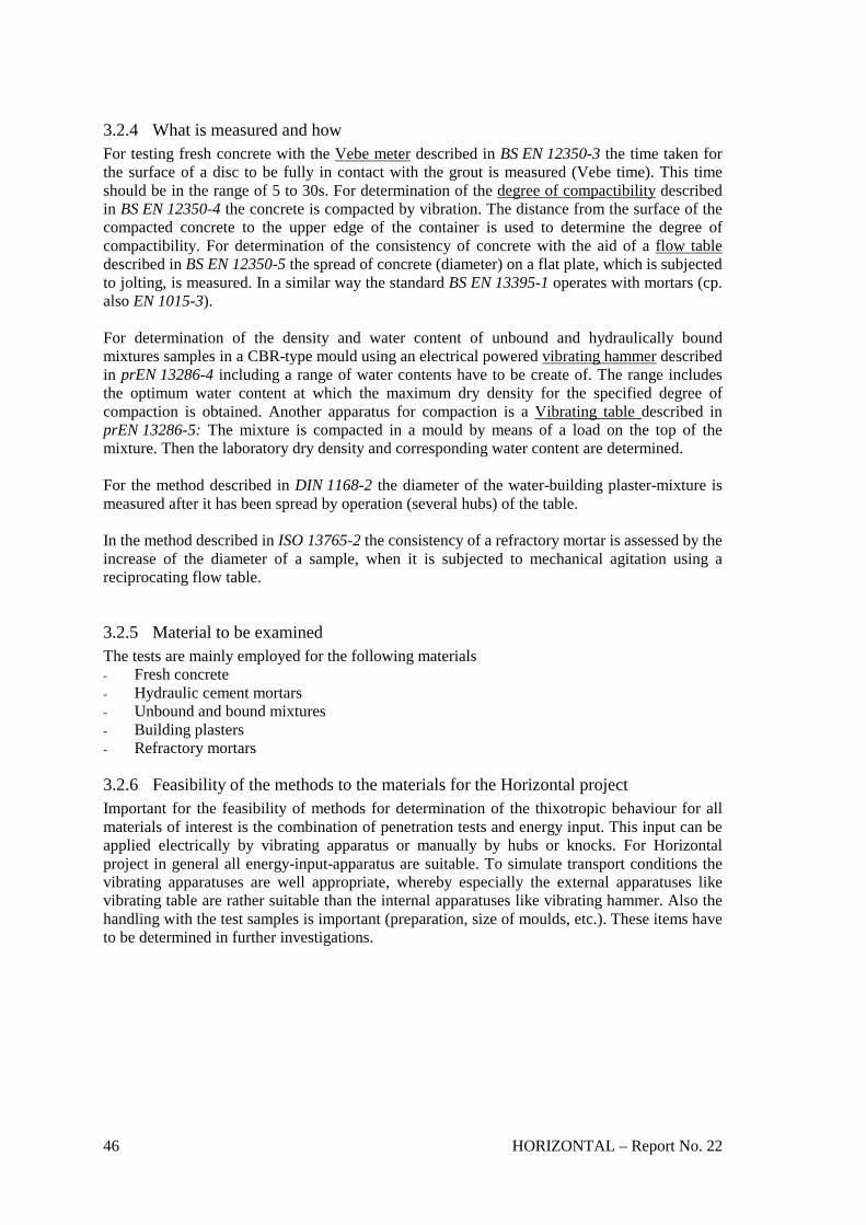
46 HORIZONTAL – Report No. 22
3.2.4 What is measured and how For testing fresh concrete with the Vebe meter described in BS EN 12350-3 the time taken for the surface of a disc to be fully in contact with the grout is measured (Vebe time). This time should be in the range of 5 to 30s. For determination of the degree of compactibility described in BS EN 12350-4 the concrete is compacted by vibration. The distance from the surface of the compacted concrete to the upper edge of the container is used to determine the degree of compactibility. For determination of the consistency of concrete with the aid of a flow table described in BS EN 12350-5 the spread of concrete (diameter) on a flat plate, which is subjected to jolting, is measured. In a similar way the standard BS EN 13395-1 operates with mortars (cp. also EN 1015-3). For determination of the density and water content of unbound and hydraulically bound mixtures samples in a CBR-type mould using an electrical powered vibrating hammer described in prEN 13286-4 including a range of water contents have to be create of. The range includes the optimum water content at which the maximum dry density for the specified degree of compaction is obtained. Another apparatus for compaction is a Vibrating table described in prEN 13286-5: The mixture is compacted in a mould by means of a load on the top of the mixture. Then the laboratory dry density and corresponding water content are determined. For the method described in DIN 1168-2 the diameter of the water-building plaster-mixture is measured after it has been spread by operation (several hubs) of the table. In the method described in ISO 13765-2 the consistency of a refractory mortar is assessed by the increase of the diameter of a sample, when it is subjected to mechanical agitation using a reciprocating flow table.
3.2.5 Material to be examined The tests are mainly employed for the following materials - Fresh concrete - Hydraulic cement mortars - Unbound and bound mixtures - Building plasters - Refractory mortars
3.2.6 Feasibility of the methods to the materials for the Horizontal project Important for the feasibility of methods for determination of the thixotropic behaviour for all materials of interest is the combination of penetration tests and energy input. This input can be applied electrically by vibrating apparatus or manually by hubs or knocks. For Horizontal project in general all energy-input-apparatus are suitable. To simulate transport conditions the vibrating apparatuses are well appropriate, whereby especially the external apparatuses like vibrating table are rather suitable than the internal apparatuses like vibrating hammer. Also the handling with the test samples is important (preparation, size of moulds, etc.). These items have to be determined in further investigations.

HORIZONTAL – Report No. 22 47
3.3 Piling behaviour
o Slump test apparatus o Compacting apparatus (e.g. Oedometer) o CPB- Cubic piling box (after E. Pasqualini [48]) o "Turned Box"
3.3.1 Standards and non-standardised methods analysed The examined methods for the determination of piling behaviour of different substances are reported in Table 11: Method Material Para-
meter Appara- tus
Standard range
Physical meaning/purpose
Utility/ field Evaluation
ASTM C143/C143M-00 Standard Test Method for Slump of Hydraulic-Cement Concrete ASTM C143-74 (-78)
Hydraulic cement concrete
Consistency (slump)
Mould Up to 37,5 mm in size, not applicable to non-plastic and non-cohesive concrete
Concrete is placed and compacted in a mould. The mould is raised, and the concrete allowed subsiding. The vertical distance between the original and displaced position of the centre of the top surface of the concrete is measured and reported as the slump of the concrete.
Laboratory and field method to test the consistency of hydraulic cement concrete
Considered and found not appropriate
BS 1881-102:1983 Testing Concrete – Part 102: Method for determination of slump
Concrete Slump (Consistency),
Mould, etc. Slump 5-175 mm, max. particle size 40mm
Filling the mould in three layers, tamping each layer, raising the mould vertically. Measuring the slump: determination of the difference between the height of the mould and the highest point of the sample being tested
Classification of the workability (table)
Considered and found not appropriate
BS 1881-103:1993 Testing Concrete – Part 103: Method for determination of compacting factor
Concrete Compacting factor (Consistency),
Sampling tray, Compacting factor apparatus, etc.
Max. particle size 40mm, compacting factor: 0.70-0.98; > 30 strokes per layer
After preparation weigh the cylinder and its contents. Mixing with concrete of the same sample, place in a cylinder and compact each layer by using compacting apparatus; weigh the cylinder. Compact the sample once more. Calculate the ratio: mass of the partially-compacted concrete / mass of the fully compacted concrete.
Classification of the workability (table)
Considered and found not appropriate
BS EN 1170-1:1998 Precast concrete products – Test method for glass-fibre reinforced cement. Part 1: Measuring the consistency of the matrix – "Slump test" method
Glass-fibre reinforced cement
Consistency,
Plastic or metallic tube, flat plate with nine numbered concentric circles etc.
Sample (200cm³) is filled in the tube, lift the tube vertically; after 30s read the number of the circle reached by the spreading matrix
water-cement ratio (suitability for pumping and compaction)
Considered and found not appropriate
ASTM D2435-96 Standard test method for one-dimensional
Soil Compression index, Young
Oedometer
Minimum sample diameter-to-height ratio =
Soil is placed into a mould and then subjected to incrementally applied
Compressibility and settlement evaluation /
Considered for further investigation

48 HORIZONTAL – Report No. 22
consolidation properties of soils
modulus 2.5 Minimum diameter = 5 cm
controlled-stress vertical loading. Settlements are measured. Primary and secondary compressibility is determined, as well as rate of consolidation.
in the laboratory
CPB test: Cubic piling box [48]
Particular and lightly compacted materials (soil, waste, etc.)
Piling behaviour
Cubic piling box
Minimum dimensions are related to the grain size of the material to be tested
Material is placed into the box and then the sidewalls are overturned. The natural slope angle of the remaining material is assessed
Determination of the piling angle of loose materials
Considered for further investigation
"Turned Box" [Method in France]
Piling behaviour
Rectangular Box
Comment: Further informations are necessary.
Table 11: Standards and non-standardised methods for piling behaviour
3.3.2 Laboratory or field test feasibility These test methods are mostly performed in the laboratory, because they require a lot of preparation. Special field test methods for determination of the piling behaviour don’t exist so far. But for some apparatuses it is possible to create for simple field tests a small-sized robust design of the laboratory apparatus according to the analysed material.
3.3.3 Apparatus The tests examined use the following types of apparatus: - Moulds, if needed: laboratory tools (results: Fig. 24) - Compacting apparatus (e.g. Oedometer) (Fig. 25; Fig. 26; Fig. 27) - Plastic or metallic tube, flat plate Besides these apparatuses another types of apparatuses, which are not reported in the standards, but may be considered as a promising tool to test the piling behaviour of the analysed materials, are the following apparatuses: - Cubic Piling Box (CPB) (Fig. 28; Fig. 29) - "Turned Box"
Fig. 24: Forms of slump [49]

HORIZONTAL – Report No. 22 49
Fig. 25: Compacting factor apparatus [50] A special form of compacting apparatus is the Oedometer
Fig. 26: Oedometer [48]
porous disk
porous disk
rigid mould
load cap
Sample

50 HORIZONTAL – Report No. 22
base
hing
sidewall
Fig. 27: Device for loading [48]
Fig. 28: Cubic Piling Box at start of test (closed sidewalls) [48]
Fig. 29: Cubic Piling Box at the end of test (opened sidewalls) [48]
Micrometer
Oedometer
Load

HORIZONTAL – Report No. 22 51
3.3.4 What is measured and how For the determination of the slump of hydraulic cement and concrete the sample is placed and compacted in a mould. The mould is raised, and the concrete allowed subsiding. The vertical distance between the original and displaced position of the centre of the top surface of the concrete is measured and reported as the slump of the concrete. For the determination of the Compacting factor within 150s of placing the sample in the upper hopper from the compacting apparatus the cylinder and its contents are weighted. After that, the concrete in the upper hopper is mixed with concrete of the same sample, place in a cylinder in six layers and compact each layer by using either the compacting bar or the vibrator (hammer); weight the cylinder again. Stroking with the compacting bar or use Vibrating hammer/ table. Calculate the ratio of the mass of partially compacted concrete dividing by the mass of fully compacted concrete. Another variant to determine the slump is following method: The sample (200cm³) is filled in a tube placed on a table with several circles, then the tube is lifted vertically; after 30s read the number of the circle reached by the spreading matrix. This test method needs a special flow table with some circles; due to the spreading the slump is determined “horizontally”, not “vertically” like the other slump test methods. The Oedometer test method covers procedures for determining the magnitude and rate of consolidation of soils when it is restrained laterally and drained axially while subjected to incrementally applied controlled stress loading. According to the standard procedure, the test is performed with constant load increment duration of 24 h. The specific loading schedule will depend on the purpose of the test. Each stress increment is maintained until excess pore water pressure is completely dissipated. During the consolidation process, measurements are made of change in the sample height and these data are used to determine the relationship between the effective stress and void ratio or strain, and the rate at which consolidation can occur by evaluating the coefficient of consolidation. The data from the consolidation test are used to estimate the magnitude and the rate of settlement of structures and embankments. The test method with the aid of the Cubic Piling Box (CPB) can be used for determining the piling angle (angle of rest) of pieces. The particular material is placed into the box and, if necessary, it can be compacted. Then the sidewalls are suddenly overturned and the stable final configuration is surveyed. The natural slope angle of the remaining material can be measured on each side of the sample remaining on the box base.
3.3.5 Material to be examined The tests are mainly employed for the following materials - Hydraulic cement (concrete) - Concrete - Glass-fibre reinforced cement - (Fine-grained) soils - (Solid) waste
3.3.6 Feasibility of the methods to the materials for the Horizontal project The standardised methods like slump tests require a certain threshold of consistency of the materials of interest. For determination of the piling behaviour new methods were developed, for example the "Turned Box" and the "Cubic Piling Box", which were created in France and Italy [48] respectively.

52 HORIZONTAL – Report No. 22
As far as piling behaviour is concerned, the Oedometer test can be used to characterize the compressibility of the material and to have an indication of how much a stratum of piled material can settle due to the loading of the material placed above. For piling behaviour, the selection of the loading schedule (maximum value, load increments and the duration of each increment) will be defined on the basis of the total height of piling and of the piling sequence. In particular, the maximum load will be necessarily lower that that used according to the standard for soils. The size of the mould that contains the sample can vary on the basis of the maximum grain size of the material to be tested. The CPB test [48] can be easily performed on particular pieces like dewatered sludges, waste and soils, etc. as well as on cohesive materials e.g. compacted materials. As far as piling behaviour is concerned, the CPB can be used to immediately and easily assess the natural slope angle of a material.

HORIZONTAL – Report No. 22 53
4. CRITICAL POINT AND RECOMMENDATIONS
In this section mainly the methods with the expression “Considered for further investigation” in the column “Evaluation” in chapter 3 are discussed. Standardisation procedures for Horizontal material examination will consist of
- Sampling, transport, preservation, storage - Pre-treatment - Measurement and evaluation of results.
4.1 Solidity
4.1.1 Comparison (discussion: pro/contra) Laboratory vane shear apparatus In general the “Vane shear strength” is one of the most commonly used parameter in the field of soil mechanics. There do exist a lot of standards. In Germany e.g. also exists such a parameter in the field of waste disposal / landfilling: For landfilling of wastes the TA Siedlungsabfall (1993) [14] gives a minimum value for the solidity of 25 kN/m². The vane shear strength of sewage sludge depends in some extent on the dry solid content, but there does exist no good correlation for different sludges. For the laboratory method there are two similar apparatus described in ASTM D4648 and ATV-Arbeitsbericht [35, 23]. Contra: For reliable measurements of the vane shear strength the investigated materials have to be cohesive. Therefore the vane testing apparatus can't be applied for non-cohesive materials like coarse-grained soils. Pro: Due to the fact that some investigations with sewage and waterworks sludges made by the laboratory vane shear apparatus (ATV-Arbeitsbericht and Wichmann et al. [23, 15]), this method should be preferred as the laboratory reference method. The calculation of the shear strength - after sample preparation and measurement -consists of the following equations after Zweck 1969 [51]):
[ / ²]vM kN mK
τ = (Eq. 4)
where M: max. torque in [kN m],
K: 2 3(1 )[ ]2 3
dd h mh
π ⋅ ⋅ ⋅ + (Eq. 5)
where d: diameter of the sheared cylinder = width of the vane, h: height of the vane. The shear strength vτ is equal to the cohesion uc of the undrained soil by (fast) shearing. For h = d:
3
32v
Md
τπ⋅=
⋅ ⋅ (Eq. 6)
For a constant shear rate the vane should be driven electrically e.g. with a velocity of 10 degree per minute, because the measured shear strength is influenced by the shear rate.

54 HORIZONTAL – Report No. 22
The characteristics of this apparatus are [16]: - length of time: ca. 60 minutes (for 3 measurements) - good handling (motorised test procedure) - reproducibility of test values (average +/- 10 %) - measuring range: 1- 180 kN/m2.
Another investigated vane testing apparatus - pocket vane shear apparatus - with several vanes of different sizes was not as suitable as other methods for determining the shear strength of materials with lower dry solids content. This aspect was pointed out by investigations performed with waterwork sludges (Wichmann et al. [15]). Penetrometer The described apparatuses are suitable to obtain reliable results of the measurements in both laboratory and field. Contra: The procedures with penetrometers are time-dependent. The measurement has to be carrying out within a fixed duration of e.g. 5 seconds. This aspect affords a precise test execution. Pro: The advantage is the great variation of the penetrometer tip according to the investigated material. There does exist a range of different tips in form of a plunger, a cone or a needle. That is why several methods are considered for further investigations. Explicit determinations, what kind of tip for a special material is the best, have to be investigated in further experiments. The procedure of calculation is quite simple: According to Hansbo (1957) [55] the sludge cohesion (undrained shear strength cu) can be derived from the cone penetration depth using the empirical equation:
2 1uK m g hc
i i⋅ ⋅ = ⋅ +
(Eq. 7)
where m: mass of the cone, g: acceleration of gravity, i: depth of penetration (indentation), h: distance between cone apex and soil surface when the cone is dropped
(normally h = 0), K: function of the apex angle of the cone (Fig. 30).
Fig. 30: Relation between the parameter K and the apex angle b of the cone

HORIZONTAL – Report No. 22 55
Further advantages are[16]: - length of time: ca. 5 minutes (for 3 measurements) - very good handling - reproducibility of test values (average +/- 10 %) - costs: ca. 40 % of the Laboratory Vane Shear Apparatus
Vicat apparatus The Vicat apparatus is a special kind of a penetration apparatus and has a tip in terms of a needle. In particular the beginning and end of solidification is measured, that means it could be verify shear strength. This aspect has to be developed in further investigations; it is one part of research needs in the field of determining solidity. Contra: Because of the shape of the penetration tip this apparatus could be only suitable for solid materials like dewatered sludges, particular bio-waste and soil. In further investigations this assumption has to be confirmed. Pro: The Vicat apparatus is a special penetration apparatus, which operates time-independent. For the measuring procedure there is a fixed depth, which the needle has to be reached. For determining the consistency of materials this aspect could be much more comfortable during the measurements. Pocket penetrometer Pro: A promising tool for simple field tests – determination of the penetrometer bearing capacity Pp – is the pocket penetrometer after Neuschäfer. After sample preparation and performance the value of penetration resistance can be read directly on the scale of the penetrometer. The penetrometer bearing capacity is determined with the aid of a nomogram, whereby the average of the values, which are indicated by the scale within three measurements, and the factor of the cone tip (see Fig. 17) are the input values. Furthermore the obtained value can be converted to the parameter “vane shear strength vτ ” by a regression line e.g. for waterworks sludges (Fig. 31). In general the equation for the regression line [23] is determined as
( 0,56) 0,156v Ppτ = − + ⋅ (Eq. 8)
0
50
100
150
200
250
300
350
400
450
500
0 20 40 60 80 100Laboratory Vane Shear Strength [kN/m2]
Pene
trom
eter
Bea
ring
Cap
acity
[kN
/m2 ]
Al-Flocculation Sludge Fe-Flocculation Sludge Iron Sludge Lime Sludge
not taken into account
coefficient of correlation r = 0,97
Fig. 31: Comparison penetrometer bearing capacity vs. laboratory vane shear strength [16]

56 HORIZONTAL – Report No. 22
Further advantages of this method are [16]: - consisting several cone tips for a wide range of materials - length of time: ca. 5 minutes (for 3 measurements) - good handling - reproducibility of test values (average +/- 8 %) - measuring range: 0 - ca. 90 kN/m2 (Vane Shear Strength) - low costs: ca. 8 % of the Laboratory Vane Shear Apparatus.
Pocket cylinder penetrometer Contra: Only a few investigations were carried out in the past. For certain conclusions further investigations will be necessary. Pro: However, this penetrometer can be also a capable apparatus for field tests, in this case for measuring the unconfined compression strength uq . The TA Siedlungsabfall (1993) [14] gives for landfilling of wastes a minimum value for the unconfined compression strength of 50 kN/m² with an axial deformation of max. 20%. It could be a helpful tool for the choice of the best suitable instrument, that there do exist such default values. The unconfined compression strength is related to the undrained shear strength uc in terms of Eq. 3 (compare chapter 1.6.1):
2u uq c= ⋅ . Further characteristics are [16]: - length of time: ca. 5 minutes (for 3 measurements) - very good handling - reproducibility of test values (average +/- 8 %) - low costs: ca. 6 % of the Laboratory Vane Shear Apparatus
4.1.2 Recommendations For the determination of the shear strength it is recommended that the triaxial test should be the absolute laboratory reference method (e.g. after DIN 18137-2 [52]).
4.1.2.1 Laboratory reference method Method 1: Laboratory vane shear apparatus (ATV-Arbeitsbericht 1989) Method 2: Penetrometer (cone or needle) Method 3: Vicat apparatus
4.1.2.2 Field test Method 1: Pocket penetrometer after Neuschäfer Method 2: Pocket cylinder penetrometer
4.2 Thixotropic behaviour of solid materials
4.2.1 Comparison (discussion: pro/contra) For standardisation of the thixotropic behaviour of solid materials a combination of standardised methods will be determined. Because of the experiences of the experts committee the combination "Penetrometer + energy-input" will be preferred. The advantage of penetrometers was already explicated in section 4.1.1. The energy input can be applied electrically by vibrating apparatus or manually by hubs or knocks. In the following only the apparatuses for the energy-input are described:

HORIZONTAL – Report No. 22 57
Contra: Vibrating hammer The vibrating hammer is an internal apparatus. During the measurement of the thixotropic behaviour this instrument could influence the procedure and therefore the results would be not certain. Pro: Vibrating table To simulate transport conditions the vibrating apparatuses, especially external apparatuses, are rather suitable than the internal apparatuses or the hand-made methods. For laboratory reference the apparatus can be more exact and thus more complex than a simple field method. For simple field test methods could be create a small-sized robust design of the laboratory method, which is driven electrically, if electric power is available, or manually by a hammer e.g.
4.2.2 Recommendations
4.2.2.1 Laboratory reference method Method 1: Penetrometers + energy-input (e.g. vibrating table)
4.2.2.2 Field test Method 1: Penetrometers + energy-input (e.g. vibrating table: small-sized apparatus, which should be easy to operate) Method 2: Penetrometers + energy input (e.g. by a hammer, if electric power is not available; adequate mould)
4.3 Piling behaviour
4.3.1 Comparison (discussion: pro/contra) Oedometer The strain condition of a material due to piling are different from those in the Oedometer, where lateral strain are prevented. Nevertheless, if the material is piled in lifts that are large enough in comparison with their height (three times at least), oedometic strains can be considered as representative. The settlement of the lower portion of the material can be evaluated. The minimum sample diameter and height should be 20 cm in order to test a representative volume of material. To avoid or reduce the friction at the interface between the material and the ring as negligible a film of grease should be placed on the internal wall of the mould before placing the sample. A compaction mould for Proctor compaction (ASTM D698-91 [53]) can be used as well. Pro: Important advantages of this method are that the procedure is well known – it is a Standard in France and USA and an overall method in practise in many other countries - and it is easy to handle. From there this method should be preferred as an additional laboratory reference method. Cubic Piling Box (CPB) The Cubic Piling Box should be preferable to the French method (No ref. 256, cp. Annex 1) because the friction between the sidewalls and the material to be tested does not affect the final result in terms of slope angle. The influence of the CPB dimension on the slope angle should be negligible provided that the side of the box is much greater of the maximum grain size of the sample. This method was originally proposed for solid waste materials having a maximum grain size of about 5 cm (Pasqualini et al., 2003 [48]). In that case, the sides of the cubic box were equal to 60 cm. For other materials a minimum of 30 cm x 30 cm should be considered in order to test a representative volume of material. The dimension of the cubic box should be at least 5

58 HORIZONTAL – Report No. 22
times greater than the maximum grain size of the sample to be tested. For detailed results of other materials for Horizontal project further investigations are necessary. Pro: Important advantages of this method are the very simple handling, the feasibility to both in the laboratory and in situ, no specialised personnel and the great variability due to the different sizes of the Cubic Piling Box related to the grain size of the material.
4.3.2 Recommendation
4.3.2.1 Laboratory reference method Method 1: Cubic Piling box (CPB) Method 2: Oedometer
4.3.2.2 Field test Method 1: Cubic Piling Box (CPB)
4.4 Summary of recommended methods The following Table 12 gives an overview of the recommended apparatuses and methods for determination of the solidity, thixotropic behaviour and piling behaviour.
Method (Apparatus) Solidity
Thixotropic behaviour of solid
materials
Piling behaviour
Penetrometer Shear strength (Lab / field)
Shear strength (Lab*/field+/**)
Vicat apparatus Shear strength (Lab)
Laboratory vane shear apparatus
Vane shear strength (Lab)
Pocket penetrometer (Neuschäfer)
Bearing capacity 1
(Field)
Pocket cylinder penetrometer
Unconfined compression strength 2 (Field)
Vibrating table Shear strength (Lab*/ field+)
Hammer (manual) Shear strength (Field**)
Cubic piling box (CPB) Piling angle (Lab/field)
Oedometer Compactibility (Lab)
Combinations for thixotropic behaviour: *+*; +++; **+** 1 Conversion into shear strength is possible 2 Conversion into undrained shear strength is possible. Table 12: Summary of the recommended apparatuses

HORIZONTAL – Report No. 22 59
4.5 Research needs
4.5.1 Basics of methods The mechanical property "solidity" can be determined directly by the shear strength or by the penetration bearing capacity resp. the unconfined compression strength, which could be both converted into shear strength. The measure of the shear strength during an energy-input in terms of vibration should describe the “thixotropic behaviour”. For the “piling behaviour” it is recommended to measure the compactibility and/or piling angle. The proposed methods for determining the parameters mentioned above are either existing standards, methods used in practise or methods, which are still in a development stage. However, for improvement of the methodologies most of the procedures and used apparatuses have to be optimised by further examinations, especially for the materials, which are discussed in the Horizontal project. For all parameter do exist methods for both laboratory and field, whereby the field test results will be compared with laboratory ones used as reference.
4.5.2 Applicability of methods to Horizontal materials Within the scope of this project the proposed methods should be applicable to the whole range of Horizontal materials (sludge, bio-waste and soil). Investigations in the past were often carried out only for several materials like sewage sludge or waterworks sludges for the parameter solidity or solid, particular bio-wastes for the parameter piling behaviour e.g.. But during these performed tests the influences of the material properties (grain size and shape, dry solids, etc.) were exhibit. By means of this knowledge it is possible to assume behaviour in general by using a special method. For adaptation of methods for all materials mentioned above or for a more exact measure it is possible to vary the dimensions of the apparatuses: For example the cone size and shape or weight of the penetrometer tip according to the consistency of the investigated sample. Another example is to vary the size of the sidewalls of the Cubic Piling Box (CPB) according to the grain size of the investigated material. These variations are promising tools for optimisation the measuring procedures. Further examinations of the proposed methods, which have to be carried out in the future, should confirm the theoretical considerations. Another item is the pre-treatment of the samples before carrying out the investigations. Especially a rough determination of the consistency before application of a special method could be advantageous for the measurement. Different types of sampling and pre-treatment are required for each method. Important for the pre-treatment are the parameters: - particle size of the material, - dimensions of the mould, - compaction of the materials, - moreover the density of the sample. For example the pre-treatment for measuring the vane shear strength is explained as follows [23]: (1) The material – if needed, dewatered – is reduced to small pieces with particle sizes of about
10 mm (2) The mould – in this case the small Proctor vessel – has an internal diameter of 100 mm und
a height of 120 mm. (3) The material is filled into the Proctor vessel in three equal portions (each about 100 mm
before compaction) and is compressed with ten knocks by the small Proctor hammer (falling weight of 2.5 kg, height of falling 300 mm, diameter of the plunger 50 mm, diameter of compensating plate 99,5 mm, compare DIN 18127 [31]).

60 HORIZONTAL – Report No. 22
(4) After finishing emplacement and before test performance the density have to determined for a uniform starting position.
The procedure mentioned above could be transmitted to the pre-treatment of measuring the shear strength or related parameters - penetration bearing capacity and unconfined compression strength – in common and also for examination of the thixotropic behaviour, whereby the shear strength is measured during shear stress. For determination of the piling behaviour (piling angle) a pre-treatment in terms of reducing to small pieces with a uniform particle size - regarding the size of the sidewalls of the Cubic Piling Box (CPB) – is proposed. It should be a similar pre-treatment like the method for the shear strength, but instead of the Proctor vessel and hammer the CPB and, if needed, according compaction apparatuses are used. For further considerations it could be helpful to cooperate with the WP 2 "Sampling".
4.5.3 Questions to be answered Research must define through interlaboratory tests precision, repeatability and reliability of methods proposed, where: - Repeatability is defined as the ability of a method to reproduce a measurement while being
tested under an unchanging set of conditions. This does not imply that the obtained value is correct, but rather that it is the same every time;
- Reproducibility is the same as repeatability, but at a different set of conditions. It is therefore a more realistic indication of a method to reproduce a measurement, whenever a predefined set of conditions is recreated.
However, as far as these methods are concerned the use of fresh sludge could be required, so the following problems arise: - the sludge characteristics change with time of storage, also considered that any preservation
practice (e.g. freezing) makes things worse; - the sludge characteristics are strongly affected by transport and handling; - fresh sludge requires particular precautions and authorization for transport by ordinary
delivering systems.
4.5.4 Route, how to answer them A protocol of validation of physical parameters will be prepared (Protocol for validation of physical parameter methods – CEN/TC308/WG1/TG3 – N29 (ref. [54] to be followed).
4.5.5 Steps to be taken ! Laboratory tests (cp. 4.5.4) ! Evaluation (cp. 4.5.4) ! Final proposal methods to be standardised (Research Report, Version 1) ! Consulting with CEN/TC's/WG's, etc. ! Revision of proposal for methods to be standardised (Research Report, Version 2) ! Interlaboratory tests included evaluation ! Final draft for methods to be standardised

HORIZONTAL – Report No. 22 61
4.6 Contacts with CEN/TC's/WG's
4.6.1 Actions - 01.08.2003: Circulation of the first draft of "Physical Properties – Solidity, Thixotropic
Behaviour and Piling Behaviour – Desk Study" (Horizontal report No. 22) with the list of standards researched (see Annex 1), proposals for draft standards (see Annex 2 – 12) and a cover letter (see Annex 13) to the members of - CEN/TC308/WG1, - CEN/TC308/WG1/TG3 and - Aldo Giove (member of the CEN/TC292/WG2). The comments, which were received until 08/20/2003, listed in Annex 14 with according comments from our side.
- 29.08.2003: Discussion of the first draft of Horizontal reports No. 21 and No. 22 during the
CEN/TC308/WG1/TG's-meeting resp. the final CEN/TC308/WG1-meeting in Hamburg. Releasing the final versions of the first drafts of Horizontal reports No. 21 and No. 22; they were circulated in professional groups and available for comments until 17.10.2003.
4.6.2 Comments received and incorporated - 05.08.2003: Comments received from J-C. Baudez: (see Annex 14, commented) - 06.10.2003: Comments received from A. Giove: (see Annex 14, commented) - 15.10.2003: Comments received from J. Winkler (see Annex 14, commented)
4.6.3 Official meetings WP7-Meetings - 12.02.2003 in Bergamo - 04.04.2003 in Ancona - 03-06.07.2003 in Ancona - 24-28.07.2003 in Bari CEN/TC308/WG1 – Meetings - 26-28.03.2003 in Oslo - 29.08.2003 in Hamburg CEN/TC308/WG1/TG3 – Meetings - 26-28.03.2003 in Oslo - 28.08.2003 in Hamburg

62 HORIZONTAL – Report No. 22
5. DRAFT STANDARD (CEN TEMPLATE)
Note: For writing horizontal standards the structure of p. 14 of the guideline was used.
5.1 Solidity
5.1.1 Laboratory reference method
5.1.1.1 Method 1 Physical properties – Determination of solidity – "Vane shear strength": Laboratory reference method by 'Laboratory vane shear apparatus' The proposal for this standard is documented in Annex 2.
5.1.1.2 Method 2 Physical properties – Determination of solidity – "Shear strength": Laboratory reference method by 'Penetrometer' The proposal for this standard is documented in Annex 3.
5.1.1.3 Method 3 Physical properties – Determination of solidity – “Shear strength”: Laboratory reference method by 'Vicat apparatus' The proposal for this standard is documented in Annex 4.
5.1.2 Field test
5.1.2.1 Method 1 Physical properties – Determination of solidity – "Bearing capacity": Field test by 'Pocket penetrometer' The proposal for this standard is documented in Annex 5.
5.1.2.2 Method 2 Physical properties – Determination of solidity – “Unconfined compression strength”: Field test by 'Pocket cylinder penetrometer' The proposal for this standard is documented in Annex 6.
5.2 Thixotropic behaviour of solid materials
5.2.1 Laboratory reference method
5.2.1.1 Method 1 Physical properties – Determination of thixotropic behaviour – "Solid materials": Laboratory reference method by combination of 'Penetrometer and Vibrating table'

HORIZONTAL – Report No. 22 63
The proposal for this standard is documented in Annex 7.
5.2.2 Field test
5.2.2.1 Method 1 Physical properties – Determination of thixotropic behaviour – "Solid materials": Field test by combination of 'Penetrometer and Vibrating table' The proposal for this standard is documented in Annex 8.
5.2.2.2 Method 2 Physical properties – Determination of thixotropic behaviour – "Solid materials": Field test by combination of 'Penetrometer and Hammer ' The proposal for this standard is documented in Annex 9.
5.3 Piling behaviour
5.3.1 Laboratory reference method
5.3.1.1 Method 1 Physical properties – Determination of piling behaviour – "Piling angle": Laboratory reference method by 'Cubic Piling Box (CPB)' The proposal for this standard is documented in Annex 10.
5.3.1.2 Method 2 Physical properties – Determination of piling behaviour – "Compactibility": Laboratory reference method by 'Oedometer test' The proposal for this standard is documented in Annex 11.
5.3.2 Field test
5.3.2.1 Method 1 Physical properties – Determination of piling behaviour – "Piling angle": Field test by 'Cubic Piling Box (CPB)' The proposal for this standard is documented in Annex 12.

64 HORIZONTAL – Report No. 22
REFERENCES
1. P. Battistoni, "Pre-treatment, measurements execution procedures and waste characteristics in the rheology of sewage sludges and the digested organic fraction of municipal solid wastes". Water Science and Technology, Vol. 36. N°11, pp 33-41, 1997 2. G.A. Carthew, C.A. Goehring, J.E. Teylingen, Development od dynamic head loss criteria for raw sludge pumping. Journal of the water Poll. Contr. Fed., 55, 472 (1983) 3. M.C. Mulbarger, S.R. Copas,J.R. . Kordic, F.M. Cash, Pipeline friction losses for wastewater sludges, J. Wat. Poll. Con. Fed., 53, 1303 (1981) 4. R.C. Frost, J.A. Ovens. A method of estimating viscosity and designing poumping system for thickened heterogeneous sludges.8th Int. Conf. on the Hydraulic Transport of Solids in Pipes, Johannesburg 25-27 August, 1982, 485 5. A. Valioulis. Relationship between settling, dewatering and rheology properties of activated sludges. Master thesis. Cornell University, Ithaca, N.Y., 1985, USA 6. Campbell H.W., Crescuolo P.J. The use of rheology for sludge characterization, wat. Sc. And Techn., 14, 475, (1982) 7. CEN/TC308/WG1/TG3: Usefulness of rheological measurement – Report No. 02 (1999) 8. P. Battistoni, G. Fava, Maria L. Ruello, "Rheology of sewage sludge (1): Development of a standardised methodology for rheological properties measurements. Ingegneria Sanitaria, N°2/90 9. Loll U., Measurement of laboratory vane shear strength as community standard of reference method for testing the suitability of dewatered sludges for use as landfill. Recycling Int., Thomè-Kozmiensky (ed.),2, 855-860,(1989) 10. DVGW-Arbeitsblatt W 221-1: Nebenprodukte und Rückstände aus Wasseraufbereitungs-anlagen: Teil 1: Grundsätze und Planungsgrundlagen, September 1999, WVGW, Bonn 11. DVGW-Arbeitsblatt W 221-3: Nebenprodukte und Rückstände aus Wasseraufbereitungsan-lagen: Teil 3: Vermeidung, Verwertung, Beseitigung, Februar 2000, WVGW, Bonn 12. Mc Tigue, N. E. and Koppers, H. M. M. and Cornwell D. A. (1990). Regulations, Characteristics, and Analytical Considerations, in: Slib, Schlamm, Sludge. Cornwall, D. A. (ed.), Koppers, H.M.M. (ed.) American Water Works Association Research Foundation (AWWARF) und Keuringsinstituut voor Waterleidingartikelen (KIWA), Denver 13. LAGA (1979). Die geordnete Ablagerung von Abfällen, Merkblatt. 14. TA Siedlungsabfall (1993): Dritte allgemeine Verwaltungsvorschrift zum Abfallgesetz, Bundesanzeiger 15. Wichmann, K; Riehl, A.: Mechanical properties of waterwork sludges – Shear strength, Wat. Sci. Tech., 1997, Vol.36, No 11, pp 43-50

HORIZONTAL – Report No. 22 65
16. L. Spinosa with the cooperation of M. Remy and K. Wichmann (2003): Measurement of sludge "Physical consistency" – Technical Report 17. Wichmann K., Akkiparambath A., Schneider S. (2002): Mengen, Zusammensetzung und Entsorgung von Wasserwerksrückständen im Jahr 1998 sowie zukünftige Datenerfassung (Auswertung der Umfrage von 1999); GWF, Wasser Abwasser, 143 Nr. 10 18. Schneider, S. (1995): Rückstände aus der Trinkwasseraufbereitung in Deutschland: Mengen, Zusammensetzung und Entsorgungswege, Abschlußbericht, ESWE-Institut, Wiesbaden 19. Meyer, E. and Dammann, E. (1995). Verwertung von Eisenhydroxidschlämmen aus der Trinkwasseraufbereitung in der Baustoffindustrie, Schlussbericht, Forschungsgemeinschaft für Wasserwirtschaft und Wasserversorgung an der Technischen Universität Hamburg-Harburg, Hamburg 20. Handbuch Wasserversorgungs- und Abwassertechnik (Band 2: Wassergewinnungs- und Wasseraufbereitungstechnik: 6.Ausgabe 21. P. Battistoni, G. Fava, F. Cecchi and P. Pavan, "Rheology of sludge from semi-dry anaerobic digestion of municipal solid waste". Environmental Technology, Vol. 12, pp 897-905, 1991 22. P. Battistoni, G. Fava, C. Stanzini, F. Cecchi and A. Bassetti, "Feed characteristics and digester operative conditions as parameters affecting the rheology of digested municipal solid wastes". Water Science Technology, Vol. 27, N°2, pp 37-45, 1993 23. ATV-Arbeitsbericht: Die Bestimmung der Deponierfähigkeit von Schlämmen mit der Referenzmethode „Laborflügelscherfestigkeit“, ATV-Fachausschuss 3.2 und 3.6, Gesellschaft zur Förderung der Abwassertechnik e.V. (GFA), 53773 Hennef: Korrespondenz Abwasser (1989), 36 (8), S. 903-909 24. Costet G, Sanglerat G., 1975: Cours pratique de mécanique des sols (tomes 1 et 2), 2ième
édition, Dunod 25. Gazbar S., 1993: Evaluation et amélioration des performances des procédés de
déshydratation mécanique des boues résiduaires. Thèse de doctorat de l’institut polytechnique de Lorraine
26. Tisot J-P, Abadie J-M., 1997: Characterisation of sludge and geochemical properties, in:
International Association on water quality, water research institute, specialist group on sludge management eds. The rheology of sludges. Congès de Bari (It)
27. J-C. Baudez: Consistency, Journal of Rheology, Vol. ?, No ?, (2002 or 2003?) 28. 29. Gehm, L.: Rheologie, Praxisorientierte Grundlagen und Glossar; Vincentz Verlag, Hannover 1998 (Coatings Compendien) 30. Schramm, G.: Einführung in Rheologie und Rheometrie; Haake Rheometer, Gebrüder Haake GmbH, Karlsruhe 1995 31. DIN 18127 (1997): Proctorversuch, Beuth-Verlag, Berlin 32. ASTM D 3080-90: Standard test method for direct shear test of soils under consolidated

66 HORIZONTAL – Report No. 22
drained conditions, Annual Book of ASTM Standards, Vol. 04.08 33. Duncan, Chester I. Jr.: Soils and Foundations for Architects and Engineers, Second Edition; Kluwer Academic Publishers; Boston/London/Dordrecht 1998 34. ASTM D2573-72 (1978): Standard test method for field vane shear test in cohesive soil, Annual Book of ASTM Standards, Vol. 04.08 35. ASTM D 4648-00: Standard test method for laboratory miniature vane shear test for saturated fine-grained clayey soil, Annual Book of ASTM Standards, Vol. 04.08 36. ASAE S313.2 (1994): Soil cone penetrometer, ASAE Standards 37. DIN 1168-2 (1975): Baugipse: Anforderungen, Prüfungen, Überwachung; Beuth-Verlag, Berlin 38. ASTM C405-82: Standard practice for estimating consistency of wet-mixed thermal insulating cement, Annual Book of ASTM Standards, Vol. 04.06 39. ASTM D217-82: Standard test methods for cone penetration of lubricating grease, Annual Book of ASTM Standards, Vol. 05.01 40. ISO 2137 (1985): Petroleum products – Lubricating grease and petrolatum – Determination of cone penetration, International Organization for Standardisation 41. ASTM D2884-93 (2002): Standard test method for yield stress of heterogeneous propellants by cone penetration method, Annual Book of ASTM Standards, Vol. 05.01 42. Fraccini (Company): Geotester (Pocket penetrometer)//Wichmann K., Riehl A.: Project: Mechanical properties of waterwork sludges – shear strength (unpublished). 43. BS EN 12350-3 (2000): Testing fresh concrete – Part 3: Vebe time, British Standard 44. BS EN 12350-5 (2000): Testing fresh concrete – Part 5: Flow table test, British Standard 45. ISO/DIS 13765-2: (Draft international standard): Refractory mortars – Part 2: Determination of consistency using the reciprocating flow table, International Organization for Standardisation 46. BS EN 13395-1: 2002: Products and systems for the protection and repair of concrete structures – Test methods – Determination of workability – Part1: Test for flow of thixotropic mortars, British Standard 47. European Committee for Standardisation (CEN): EN 13286-4 (2003): Unbound and hydraulically bound mixtures – Part 4: Test methods for laboratory reference density and water content – vibrating hammer, European Standard 48. Pasqualini E., Patacchini C., Stella M. (2003) Mechanical characterisation of municipal solid waste (in Italian). Proc. Annual Meeting of the Researchers in Geotechnics, IARG 2003. 49. BS 1881: Part 102 (1983): Testing concrete-Part 102: Method for determination of slump, British Standard 50. BS 1881-103 (1993): Testing concrete – Part 103: Method for determination of compacting factor, British Standard 51. Zweck, H.: Baugrunduntersuchung d. Sonden, Verlag Ernst + Sohn, Berlin/München (1969)

HORIZONTAL – Report No. 22 67
52. DIN 18137-2 (1990): Baugrund, Versuche und Versuchsgeräte; Bestimmung der Scherfestigkeit; Triaxialversuch, Beuth-Verlag, Berlin 53. ASTM D698-00a: Standard Test Methods for Laboratory Compaction Characteristics of Soil Using Standard Effort (12,400 ft-lbf/ft3 (600 kN-m/m3)), Annual Book of ASTM Standards, Vol. 04.08 54. Protocol for validation of physical parameter methods – CEN/TC308/WG1/TG3 – N29 (2003) 55. Hansbo, S. (1994): Foundation Engineering, Developments in Geotechnical Engineering, 75, Elsevier

68 HORIZONTAL – Report No. 22
ANNEX 1
List of standards and non-standardised methods

n° ref standard method title / description keyword on webstatus / comments Solidity Flowability
Thixotropic behaviour
Piling behaviour
1 ASAE EP542 FEB99 Procedures for Using and Reporting Data Obtained with the Soil Cone Penetrometer Soil webstore.ansi.org x (-)
2 ASAE S313.2 DEC94 Soil Cone Penetrometer Soil webstore.ansi.org x (+)3 ASAE S313.3 FEB99 Soil Cone Penetrometer Soil webstore.ansi.org x (+)4 ASTM C110-02 physical testing of quicklime*
5 ASTM C1170-91 (1998) e1Standard Test Methods for Determining Consistency and Density of Roller-Compacted Concrete Using a Vibrating Table
Cementitious & concrete materials; Consistency
www.astm.org; www.beuth.dex (-) x (-)
6 ASTM C1176-92 (1998)Standard Practice for Making Roller-Compacted Concrete in Cylinder Molds Using a Vibrating Table
Cementitious & concrete materials
www.astm.org; x (-)
7 ASTM C1339-02Standard Test Method for FLOWABILITY and Bearing Area of Chemical-Resistant Polymer Machinery Grouts Flowability www.astm.org
8 ASTM C1362-97 (2002) flow of ... concrete x (+)
9 ASTM C143/C143M-00 Standard Test Method for Slump of Hydraulic Cement Concrete
Cementitious & concrete materials; cement
www.astm.org; webstore.ansi.org x (+) x (+)
10 ASTM C1437-01 Standard Test Method for Flow of Hydraulic Cement Mortar
Cementitious & concrete materials; cement
www.astm.org; webstore.ansi.org x (+)
11 ASTM C143-74Standard test method for slump of portland cemente concrete** (used for waste consistency) Consistency www.astm.org; x (+)
12 ASTM C1444-00 Flowability x (-)
13 ASTM C1445-99 Standard Test Method for Measuring Consistency of Castable Refractory Using a Flow Table Consistency webstore.ansi.org x (+)
14 ASTM C187-98 Standard Test Method for Normal CONSISTENCY of Hydraulic Cement* Consistencywww.astm.org;
x (+)
15 ASTM C191a:2001Standard Test Method for Time of Setting of Hydraulic Cement by Vicat Needle Needle www.beuth.de x (-)
16 ASTM C230/C230M-98e2 Standard Specification for Flow Table for Use in Tests of Hydraulic Cement Cement; flowabilitywebstore.ansi.org; www.astm.org x (+)
17 ASTM C405-82 (1997) Standard Practice for Estimating Consistency of Wet-Mixed Thermal Insulating Cement Consistency
webstore.ansi.org; www.beuth.de x (+) x (+)
18 ASTM C472-99 physical testing of gypsum x (+)19 ASTM C639-01 flow properties of elastomeric sealants x (+)
20 ASTM C807:1999Standard Test Method for Time of Setting of Hydraulic Cement Mortar by Modified Vicat Needle Needle www.beuth.de x (+) x (+)
21 ASTM C939-97 (opp '99 opp '02)Standard Test Method for Flow of Grout for Preplaced-Aggregate Concrete (Flow Cone Method)
Cementitious & concrete materials; flowability www.astm.org x (+)
22 ASTM C995-01Standard Test Method for Time of Flow of Fiber-Reinforced Concrete Through Inverted Slump Cone
Cementitious & concrete materials; flowability www.astm.org x (+)
23 ASTM D1084-97 viscosity of adhesives* x (+)24 ASTM D1092-99 viscosity of lubricating greases x (-)25 ASTM D1238-00 Melt flow index www.cdcmp.it/testing.html x (+)26 ASTM D1321a:2002 Standard Test Method for Needle Penetration of Petroleum Waxes* Needle www.beuth.de
27 ASTM D1338-99 Standard Practice for Working Life of Liquid or Paste Adhesives by Consistency and Bond Strength* Consistency webstore.ansi.org
28 ASTM D1556-90Standard test method for Density and Unit Weight of soil in place by the Sand-Cone Method Soil www.astm.org x (-)
29 ASTM D1558-99 Standard Test Method for Moisture Content Penetration Resistance Relationships of Fine-Grained Soils Soil webstore.ansi.org x (+)
HorizontalNo21No22Anx1 101203 1/9

30 ASTM D1586-99 Standard Test Method for Penetration Test and Split-Barrel Sampling of Soils Soil webstore.ansi.org x (-)
31 ASTM D1601-99 Standard Test Method for Dilute Solution VISCOSITY of Ethylene Polymers Viscosity www.astm.org x (+)32 ASTM D1725-62 (1996)e1 viscosity of resin solutions x (+)
245 ASTM D1883-99 (-94 )Standard Test Method for CBR (California Bearing Ratio) of Laboratory-Compacted Soils x (+)
33 ASTM D2161-93 (1999)e2Standard Practice for Conversion of Kinematic VISCOSITY to Saybolt Universal VISCOSITY or to Saybolt Furol VISCOSITY Viscosity www.astm.org x (-)
247 ASTM D2166: 2000Standard Test Method for Unconfined Compressive Strength of Cohesive Soil
Unconfined compression strength www.beuth.de x (+)
34 ASTM D2170-01 a viscosity of asphalts x (+)35 ASTM D2171-01 viscosity of asphalts by vacuum capillary viscometers x (+)36 ASTM D217-97 cone penetration of lubricant grease x (+)
37 ASTM D2196-81Standard test methods for rheological properties of non-Newtonian materials by rotational (Brookfield type) viscometer*** x (+) x (+)
38 ASTM D2217:1985 (1998)Standard Practice for Wet Preparation of Soil Samples for Particle-Size Analysis and Determination of Soil Constants Soil www.beuth.de x (-)
39 ASTM D2270-93 (1998) Standard Practice for Calculating VISCOSITY Index From Kinematic VISCOSITY at 40 and 100°C Viscosity www.astm.org x (+)
254 ASTM D 2435-96 Standard test method for one-dimensional consolidation properties of soils Oedometer www.astm.org x (+)40 ASTM D2556-93 a(1997) viscosity of adhesives ... shear rate dependent flow properties* x (+)41 ASTM D2573:2001 Standard Test Method for Field Vane Shear Test in Cohesive Soil Soil, Vane
webstore.ansi.org; www.beuth.de x (+)
248 ASTM D2850: 2003Standard Test Method for Unconsolidated-Undrained Triaxial CompressionTest on Cohesive Soils Triaxial strength www.beuth.de x (+)
42 ASTM D2857-95 (2001) Standard Practice for Dilute Solution VISCOSITY of Polymers Viscosity www.astm.org x (+)
43 ASTM D2884:1993 (1998)Standard Test Method for Yield Stress of Heterogeneous Propellants by Cone Penetration Method Cone www.beuth.de x (+) x (+)
44 ASTM D2983-02a viscosity of lubricants ... brookfield viscometers x (+)
244 ASTM D3080-90Standard Test Methods for Direct Shear Test of Soil Under Consolidated Drained Condition Solidity x (+)
45 ASTM D3441-98 Standard Test Method for Deep, Quasi-Static, Cone and Friction-Cone Penetration Tests of Soil Soil webstore.ansi.org x (+) x (+)
46 ASTM D3668:1978 (1985)Standard Test Method for Bearing Ratio of Laboratory Compacted Soil-Lime Mixtures Soil www.beuth.de x (-) x (-)
47 ASTM D3999-91 (1996) Standard Test Methods for the Determination of the Modulus and Damping Properties of Soils Using the Cyclic Triaxial Apparatus* Soil www.beuth.de x (-)
243 ASTM D4016-93 Standard Test Methods for Viscosity of Chemical Grouts by Brookfield Viscometer (laboratory method) Viscosity x (+)
48 ASTM D421:1985 (1998)Standard Practice for Dry Preparation of Soil Samples for Particle-Size Analysis and Determination of Soil Constants Soil www.beuth.de x (-)
49 ASTM D424-59 (reapproved 1971) Standard Test Methods for Plastic Limit and Plasticity Index of SOILs**changed in D4318 / 1983
50 ASTM D4283-98 viscosity of silicone fluids x (-)
51 ASTM D4318-00Standard Test Methods for Liquid Limit, Plastic Limit, and Plasticity Index of SOILs* Soil; plasticity www.astm.org x (+)
52 ASTM D4320:1993Standard Test Method for Laboratory Preparation of Chemically Grouted Soil Specimens for Obtaining Design Strength Parameters Soil www.beuth.de x (-)
53 ASTM D445-01 viscosity of transparent and opaque liquids x (+)54 ASTM D4452:1985(2002)e1 Standard Test Methods for X-Ray Radiography of Soil Samples Soil www.beuth.de55 ASTM D446-00 kapillary kinematic viscometers* x (+)56 ASTM D4624-93 (1998) viscosity by capillary viscometer* x (+)
HorizontalNo21No22Anx1 101203 2/9

57 ASTM D4648:2000Standard Test Method for Laboratory Miniature Vane Shear Test for Saturated Fine-Grained Clayey Soil Vane www.beuth.de x (+) x (+)
58 ASTM D4682-87 (2002)Standard Specification for Miscibility with Gasoline and FLUIDITY of Two-Stroke-Cycle Gasoline Engine Lubricants Fluidity www.astm.org x (-)
59 ASTM D4684-02a viscosity of engine oils x (+)60 ASTM D4843-88 (1999) wetting and drying test of solid wastes*61 ASTM D4957-95 viscosity of asphalt ... by vacuum capillary viscometers* x (+)62 ASTM D4989-90 a(1999) apparent viscosity (flow) of bitumens (plastometers)* x (-)63 ASTM D5099-93 (1998) rubber ... processing properties using capillary rheometry x (+)
64 ASTM D5102:1996Standard Test Method for Unconfined Compressive Strength of Compacted Soil-Lime Mixtures Soil www.beuth.de x (+)
65 ASTM D5183:1995(1999)e1Standard Test Method for Determination of the Coefficient of Friction of Lubricants Using the Four-Ball Wear Test Machine
Mechanical properties www.beuth.de
66 ASTM D5225-98Standard Test Method for Measuring Solution VISCOSITY of Polymers with a Differential Viscometer Viscosity www.astm.org x (+)
67 ASTM D5311:1992 (1996) Standard Test Method for Load Controlled Cyclic Triaxial Strength of Soil Soil www.beuth.de x (+)68 ASTM D5422-00 flow properties ... by screw-extrusion capillary rheometer* x (+)
69 ASTM D5478:1998Standard Test Methods for Viscosity of Materials by a Falling Needle Viscometer* Needle www.beuth.de x (-) x (+)
70 ASTM D5520-94(2001)Standard Test Method for Laboratory Determination of Creep Properties of Frozen Soil Samples by Uniaxial Compression Soil www.beuth.de x (-)
71 ASTM D5574:1994(1999)e1Standard Test Methods for Establishing Allowable Mechanical Properties of Wood-Bonding Adhesives for Design of Structural Joints
Mechanical properties www.beuth.de
72 ASTM D558:1996Standard Test Methods for Moisture-Density Relations of Soil-Cement Mixtures Soil www.beuth.de
73 ASTM D562-01 Standard Test Method for Consistency of Paints Measuring Krebs Unit (KU) Visosity Using the Stormer-Type Viscometer Consistency webstore.ansi.org x (+)
74 ASTM D5778:1995(2000)Standard Test Method for Performing Electronic Friction Cone and Piezocone Penetration Testing of Soils Soil www.beuth.de x (+)
75 ASTM D5873:2000Standard Test Method for Determination of Rock Hardness by Rebound Hammer Method Soil, properties www.beuth.de x (-)
76 ASTM D6067:1996e1Standard Guide for Using the Electronic Cone Penetrometer for Environmental Site Characterization Soil, properties www.beuth.de x (-)
77 ASTM D6080-97 viscosity of hydraulic fluids* x (+)78 ASTM D6103-97 consistency of controlled low strength material* x (+)79 ASTM D6204-01 rubber ... rheological properties ... rotorless shear rheometers x (+)
80 ASTM D6243:1998Standard Test Method for Determining the Internal and Interface Shear Resistance of Geosynthetic Clay Liner by the Direct Shear Method Shearing strength www.beuth.de x (+)
81 ASTM D6351-99 fluidity and appearance of hydraulic fluids* x (+)
82 ASTM D6351-99Standard Test Method for Determination of Low Temperature FLUIDITY and Appearance of Hydraulic Fluids Fluidity www.astm.org x (-)
83 ASTM D6467:1999Standard Test Method for Torsional Ring Shear Test to Determine Drained Residual Shear Strength of Cohesive Soils Soil, properties www.beuth.de x (-)
84 ASTM D6496:1999
Standard Test Method for Determining Average Bonding Peel Strength Between the Top and Bottom Layers of Needle-Punched Geosynthetic Clay Liners Needle www.beuth.de x (-)
85 ASTM D6528:2000Standard Test Method for Consolidated Undrained Direct Simple Shear Testing of Cohesive Soils Soil www.beuth.de x (-)
86 ASTM D6572:2000Standard Test Methods for Determining Dispersive Characteristics of Clayey Soils by the Crumb Test Soil, properties www.beuth.de
87 ASTM D666Method for Conversion of Kinematic VISCOSITY of Saybolt Furol VISCOSITY (Withdrawn 1961), Replaced By D2161 Viscosity www.astm.org
88 ASTM D6682-01 Flowability x (-)89 ASTM D6773-02 Flowability x (-)90 ASTM D6821-02 viscosity of lubricants in constant shear stress viscometers x (+)
HorizontalNo21No22Anx1 101203 3/9

91 ASTM D937-97 Standard test method for cone penetration of petrolatum x (+)92 ASTM D97-66 Pour Point of Petroleum oils Sliding www.astm.org
93 ASTM F1080-93(2002) Standard Test Method for Determining the Consistency of Viscous Liquids Using a Consistometer * Consistency
webstore.ansi.org; www.beuth.de x (+)
94 ASTM F1470-02 fastener sampling ... mechanical properties
95 BS 1881-102: 1983 Testing concrete. Method for determination of slumpConsistency; concrete www.bsi.org.uk
Current, Superseded x (+) x (+)
96 BS 1881-103:1993 Testing concrete. Method for determination of compacting factor Concrete www.bsi.org.ukCurrent, Superseded x (+)
97 BS 1881-104:1983 Testing concrete. Method for determination of Vebe timeConsistency; concrete www.bsi.org.uk
Current, Superseded x (-) x (-)
98 BS 1881-105:1984 Testing concrete. Method for determination of flowConsistency; concrete www.bsi.org.uk
Current, Superseded x (+)
99 BS 2000-179:1993Methods of test for petroleum and its products. Determination of cone penetration of petrolatum Consistency www.bsi.org.uk Current x x (-)
100 BS 2000-49:1993Methods of test for petroleum and its products. Determination of needle penetration of bituminous material Consistency www.bsi.org.uk
Withdrawn, Superseded x (+) x (+)
101 BS 2000-50:1993Methods of test for petroleum and its products. Determination of cone penetration of lubricating grease Consistency www.bsi.org.uk Current x x (-)
102 BS 3712:Part 1:1991Building and construction sealants. Methods of test for homogeneity, relative density, extrudability, penetration Consistency www.bsi.org.uk
Withdrawn, Revised x (+) x (+)
103 BS 4550:Part 3:Section 3.5:1978Methods of testing cement. Physical tests. Determination of standard consistence Consistency www.bsi.org.uk
Withdrawn, Superseded x (-)
104 BS EN 1015-3:1999Methods of test for mortar for masonry. Determination of consistence of fresh mortar (by flow table) Concrete www.bsi.org.uk Current x (+)
105 BS EN 1015-4:1999Methods of test for mortar for masonry. Determination of consistence of fresh mortar (by plunger penetration)
Consistency; concrete www.bsi.org.uk Current x (-)
106 BS EN 1170-1:1998Precast concrete products. Test method for glass-fibre reinforced cement. Measuring the consistency of the matrix. 'Slump test' method
Consistency; plasticity www.bsi.org.uk Current x (+)
107 BS EN 12274-3:2002 Slurry surfacing. Test methods. Consistency Consistency; slurry www.bsi.org.uk Current x (+)
108 BS EN 12350-2:2000 Testing fresh concrete. Slump testConsistency; concrete www.bsi.org.uk x
109 BS EN 12350-3:2000 Testing fresh concrete. Vebe testConsistency; concrete www.bsi.org.uk Current x (+) x (+)
110 BS EN 12350-4:2000 Testing fresh concrete. Degree of compactabilityConsistency; concrete www.bsi.org.uk Current x (+) x (+)
111 BS EN 12350-5:2000 Testing fresh concrete. Flow table testConsistency; concrete www.bsi.org.uk Current x (+) x (+)
112 BS EN 13395-1:2002
Products and systems for the protection and repair of concrete structures. Test methods. Determination of workability. Test for flow of thixotropic mortars Consistency www.bsi.org.uk Current x (+)
246 BS EN 196-3:1995 Part 3. Determination of setting time and soundness Consistency; concrete www.bsi.org.uk Current x (+)
113 BS EN 535:1991 Method for determination of flow time of paints by use of flow cups Consistency www.bsi.org.ukWithdrawn, Superseded x (-)
114 CEN 00104206 prEN 14117 viscosity of cementitious products* x (+)115 CEN 00193033 prEN ISO 14678 adhesives resistance to flow* x (-)116 CEN 00193070 prEN 14256 adhesives resistance to static load117 CEN 00227124 prEN 13286-4 vibrating hammer Road materials x (+)118 CEN 00227125 prEN 13286-5 vibrating table Road materials x (+)119 CEN 00227146 prEN 13880-2 cone penetration Road materials x (+)120 CEN 00227149 prEN 13880-5 flow resistance* Road materials x (+)121 CEN 00249471 prEN ISO 307rev determination of viscosity x (-)
122 CEN 00249479 prEN ISO 1628 rev viscosity ... capillary viscometers** x (-)
HorizontalNo21No22Anx1 101203 4/9

123 CEN 00249494 IS=/DIS 12058-2 viscosity ... falling ball x (-)124 CEN 00249531 prEN ISO 307 rev determination of viscosity x (-)125 CEN 00336005 bitumen ...consistency* x (-)126 CEN 00336024 prEN 13702-1 cone and plate viscometer127 CEN 00336025 prEN 13702-2 coaxial viscometer x (+)128 CEN 00336034 prEN 13302 rotating spindle apparatus x (+)
129 CNR UNI 10014:1964 Prove sulle terre. Determinazione dei limiti di consistenza (o di Atterberg) di una terra. Consistency; soil www.uni.com
130 DIN 1048-1: 1991-06 Testing concrete; testing of fresh concrete Consistency www.beuth.de x (-)
131 DIN 1168-2:1975-07 Building Plasters; Requirements, Testing, Control Festigkeit (Solidity) www.beuth.de x (+) x (+)
132 DIN 18122-1:1997-07Soil, investigation and testing - Consistency limits - Part 1: Determination of liquid limit and plastic limit (FOREIGN STANDARD) Consistency; soil
webstore.ansi.org ; www.beuth.de x (-)
133 DIN 18125-1:1997-08 Soil, investigation and testing - Determination of density of soil - Part 1: Laboratory tests Soil, properties www.beuth.de x (-)
134 DIN 18125-2:1999-08Soil investigation and testing - Determination of density of soil - Part 2: Field tests Soil, properties www.beuth.de x (-)
135 DIN 4094-4:2002-01 Subsoil - Field testing - Part 4: Field vane test Vane www.beuth.de x (+)
136 DIN 51350-6: 1984-01Testing of lubricants - Testing in the Shell four-ball tester - Part 6: Determination of shear stability of lubricating oils containing polymers Consistency www.beuth.de
137 DIN 51382: 1996-08
Testing of lubricants - Determination of shear stability of lubricating oils containing polymers - Method with Diesel injection nozzle, relative viscosity loss due to shear Shearing strength www.beuth.de
138 DIN 51389-3:1998-10
Determination of lubricants - Mechanical testing of hydraulic fluids in the vane-cell-pump - Part 3: Method B for aqueous not easily inflammable hydraulic fluids Vane www.beuth.de
139 DIN 51580:1989-04 Testing of petroleum waxes; determination of cone penetration Cone www.beuth.de x (+)
140 DIN 53018-1 Viscometry; Measurement of the Dynamic Viscosity of Newtonian Fluids with Rotational Viscometers; Principles (FOREIGN STANDARD) Viscosity webstore.ansi.org x (-)
141 DIN 53018-2
Viscometry; Measurement of the Dynamic Viscosity of Newtonian Fluids with Rotational Viscometers; Sources of Errors and Corrections concerning Cylinder; Rotation Viscometers (FOREIGN STANDARD) Viscosity webstore.ansi.org x (-)
142 DIN 53019-2
Viscosimetry - Determination of viscosity and flow curves with rotational viscosimeters - Part 2: Viscosimeter calibration and determination of the uncertainty of measurement (FOREIGN STANDARD) Viscosity webstore.ansi.org x (-)
143 DIN 53735 Melt flow index www.cdcmp.it/testing.html x (-)
144 DIN EN 1015-3: 1999-04
Methods of test for mortar for masonry - Part 3: Determination of consistence of fresh mortar (by flow table); German version EN 1015-3:1999 Consistency www.beuth.de x (-)
145 DIN EN 1015-4: 1998-12
Methods of test for mortar for masonry - Part 4: Determination of consistence of fresh mortar (by plunger penetration); German version EN 1015-4:1998 Consistency www.beuth.de x (-)
146 DIN EN 1170-1
Precast concrete products - Test method for glass-fibre reinforced cement - Part 1: Measuring the consistency of the matrix by the 'Slump test' method (FOREIGN STANDARD) Consistency webstore.ansi.org x (-)
147 DIN EN 12274-3 Slurry surfacing - Test method - Part 3: Consistency; English version of DIN EN 12274-3 (FOREIGN STANDARD) Consistency; slurry webstore.ansi.org
148 DIN EN 13395-1:2002-09
Products and systems for the protection and repair of concrete structures - Test methods; Determination of workability - Part 1: Test for flow of thixotropic mortars; German version EN 13395-1:2002 Thixotropic www.beuth.de x (-)
149 DIN EN 13395-2:2002-09
Products and systems for the protection and repair of concrete structures - Test methods; Determination of workability - Part 2: Test for flow of grout or mortar; German version EN 13395-2:2002 www.beuth.de
HorizontalNo21No22Anx1 101203 5/9

150 DIN EN 13395-3:2002-09
Products and systems for the protection and repair of concrete structures - Test methods; Determination of workability - Part 3: Test for flow of repair concrete; German version EN 13395-3:2002 www.beuth.de
151 DIN EN 1426:1999-12Bitumen and bituminous binders - Determination of needle penetration; German version EN 1426:1999 Needle www.beuth.de x (+)
152 DIN EN 2243-6: 1997-02Aerospace series - Structural adhesives, test methods - Part 6: Determination of shear stress and shear strain Shearing strength www.beuth.de Draft standard x (-) x (-)
153 DIN EN 3801:1995-06Aerospace series - Anaerobic polymerisable compounds - Torque strength 5 Nm; thixotropic index 8 Thixotropic www.beuth.de Draft standard x (-) x (-)
154 DIN ISO 2137:1997-08Petroleum products - Lubricating grease and petrolatum Determination of cone penetration (ISO 2137:1985) Cone www.beuth.de x (+)
155 FD X33-011 December 2002 Characterisation of sludges - Sludge management in relation to use or disposal Sludge www.afnor.fr/portail.asp
Status: Documentation sheet
156 ISO 1099:1975-11 Metals; Axial load fatigue testing Mechanical properties www.beuth.de
157 ISO 11443:1995 February 1995Plastics. Determination of the fluidity of plastics using capillary and slit-die rheometers. Viscosity www.afnor.fr/portail.asp
Status : International standard x (+)
158 ISO 12058:1997 Part1 and Part 2 plastics viscosity falling ball x (+)159 ISO 12115:1997 fibre-reinforced plastics ... flowability x (+)
160 ISO 13765-2:2001-12 Refractory mortars. Part 2: Determination of consistency using the reciprocating flow table Consistency www.beuth.de Draft standard x (+)
161 ISO 1433:1995-12 Rubber, vulcanized - Preferred gradations of properties Physical properties www.beuth.de162 ISO 14446:1999 binders for paints viscosity163 ISO 1599:1990 December 1991 French equivalent standard(s) : NF EN ISO 1599 Viscosity www.afnor.fr/portail.asp x (+)
164 ISO 1658:1994-02 Natural rubber (NR); evaluation procedure Physical properties www.beuth.de
249 ISO 2039-1: 2001-12 Plastics - Determination of hardness - Part 1: Ball indentation method Penetration ball www.beuth.de x
165 ISO 2137:1985-11Petroleum products; Lubricating grease and petrolatum; Determination of cone penetration Cone www.beuth.de x (+)
166 ISO 2307:1990 ropes mechanical properties
167ISO 2431/ Technical Corrigendum 1:1994-06
Paints and varnishes - Determination of flow time by use of flow cups; Technical Corrigendum 1 Consistency www.beuth.de x (+)
168ISO 2431/Technical Corrigendum 2:1999-04
Paints and varnishes - Determination of flow time by use of flow cups; Technical Corrigendum 2 Consistency www.beuth.de x (+)
169 ISO 2431:1993-02 Paints and varnishes; determination of flow time by use of flow cups Consistency www.beuth.de x (+)170 ISO 2555:1989 liquid resins viscosity* x (+)
171 ISO 2884-1:1999-10 Paints and varnishes - Determination of viscosity using rotary viscometers - Part 1: Cone-and-plate viscometer operated at a high rate of shear www.beuth.de
172 ISO 289-1:1994-07Rubber, unvulcanized - Determinations using a shearing-disc viscometer - Part 1: Determination of Mooney viscosity Shearing strength www.beuth.de
173 ISO 3049:1974 gypsum physical properties x (-)
174 ISO 3051:1974-07 Gypsum plasters; Determination of mechanical properties Festigkeit (Solidity) www.beuth.de x (-)175 ISO 3104:1994 petroleum products viscosity* x (+)
176 ISO 3219:1993 October 1993
Plastics - Polymers/resins in the liquid state or as emulsions or dispersions - Determination of viscosity using a rotational viscometer with defined shear rate * Viscosity
webstore.ansi.org; www.afnor.fr/portail.asp
Status : International standard x (+)
177 ISO 3666:1998 water viscosity*
HorizontalNo21No22Anx1 101203 6/9

178 ISO 4103:1979 June 1979 Concrete -- Classification of consistency * Consistency
webstore.ansi.org; www.afnor.fr/portail.asp; www.beuth.de
Status : International standard x (-) x (+)
179 ISO 4109:1980 February 1980 Determination of the consistence of fresh concrete -- Slump test Consistency
webstore.ansi.org ; www.afnor.fr/portail.asp; www.beuth.de
Status : International standard x
180 ISO 4110:1979 December 1979 Fresh concrete. Determination of the consistency. Vebe test. Consistency; flowability
www.afnor.fr/portail.asp; webstore.ansi.org; www.beuth.de
Status : International standard x (-)
181 ISO 4111:1979 December 1979 Fresh concrete. Determination of consistency. Degree of compactibility (compaction index). *
Consistency; flowability
www.afnor.fr/portail.asp; webstore.ansi.org; www.beuth.de
Status : International standard x
182 ISO 5270:1998 pulps physical properties* x (-) x (-)183 ISO 5530-1:1997 wheat flour physical properties
184 ISO 556:1980-11 Coke (greater than 20 mm in size); Determination of mechanical strength Mechanical properties www.beuth.de x (-)
185 ISO 6388:1989 surface active agents flow properties
186 ISO 6721-10:1999 plastics mechanical propertiesMechanical properties www.beuth.de
187 ISO 8130-5:1992 coating powders flow properties
188 ISO/DIS 1099:2002-11Metallic materials - Fatigue testing - Axial force controlled method (Revision of ISO 1099:1975)
Mechanical properties www.beuth.de Draft standard
189 ISO/DIS 11273-1:1995-11Soil quality - Determination of aggregate strength - Part 1: Tensile strength measurement (crushing test) Soil, properties www.beuth.de Draft standard
190 ISO/DIS 13737:1996-02Petroleum products - Lubricating greases - Determination of low-temperature cone penetration Cone www.beuth.de Draft standard x
191 ISO/DIS 13765-1:2001-12 Refractory mortars. Part 1: Determination of consistency using the penetrating cone Consistency www.beuth.de Draft standard x (+)
192 ISO/DIS 2884:1997-11 Paints and varnishes - Determination of viscosity at a high rate of shear by a cone-and-plate viscometer (Revision of ISO 2884:1974) www.beuth.de Draft standard x (-)
193 ISO/DIS 35:2001-10Natural rubber latex concentrate - Determination of mechanical stability (Revision of ISO 35:1995)
Mechanical properties www.beuth.de Draft standard x (-)
194 ISO/FDIS 2884-2:2002-10 Paints and varnishes - Determination of viscosity using rotary viscometers - Part 2: Disc or ball viscometer operated at a specified speed www.beuth.de Draft standard x (+)
195 ISO/TR 7517:1983-12 Coke; Comparison of different tests used to assess the physical strength Festigkeit (Solidity) www.beuth.de x (-)
196 NF EN 1015-3 Methods of test for mortar for masonry. Part 3 : determination of consistence of fresh mortar (by flow table). Consistency www.afnor.fr/portail.asp
Status : Certified standard x (-)
197 NF EN 1015-4 October 1999 Methods of test for mortar for masonry. Part 4 : determination of consistence of fresh mortar (by plunger penetration). Consistency www.afnor.fr/portail.asp
Status : Certified standard
198 NF EN 1170-1 May 1998 Precast concrete products. Test method for glass-fibre reinforced cement. Part 1 : measuring the consistency of the matrix, "Slump test" method. Consistency www.afnor.fr/portail.asp
Status : Certified standard
199 NF EN 12350-3 December 1999 Testing fresh concrete - Part 3 : Vebe test Consistency www.afnor.fr/portail.asp
Status : Certified standard x (-)
200 NF EN 12350-4 March 2001 Testing fresh concrete - Part 4 : degree of compactability Consistency www.afnor.fr/portail.asp
Status : Certified standard
201 NF EN 12350-5 December 1999 Testing fresh concrete - Part 5 : flow table test Consistency www.afnor.fr/portail.asp
Status : Certified standard x (-)
HorizontalNo21No22Anx1 101203 7/9

202 NF EN ISO 3219 November 1994
Plastics. Polymers/resins in the liquid state or as emulsions or dispersions. Determination of viscosity using a rotational viscometer with defined shear rate. Viscosity www.afnor.fr/portail.asp
Status : Certified standard x (-)
203 NF P18-507 November 1992 Additions for concrete. Water retention. Method for measurement of fluidity by flowing with the "cone de marsh".
Consistency; fluidity; Cone
www.afnor.fr/portail.asp; www.beuth.de
Status : Certified standard x (+)
204 NF P94-051 March 1993 Soil : inverstigation and testing. Determination of Atterberg's limits. Liquid limit test using cassagrande apparatus. Plastic limit test on rolled thread.
Consistency; plasticity www.afnor.fr/portail.asp
Status : Certified standard
205 NF P94-052-1 November 1995 Soil : investigation and testing. Atterberg limit determination. Part 1 : liquid limit. Cone penetrometer method. Consistency www.afnor.fr/portail.asp
Status : Certified standard x (-) x (+)
206 NF T30-029 October 1980 Paints. Method of use a rotational viscosimeter for measuring the apparent dynamic viscosity of varnishes, paints and similar preparations. Viscosity www.afnor.fr/portail.asp
Status : Documentation sheet x (+)
207 NF T30-601 November 1977 Paints. Paint coatings for indoor use. Measurement of consistency by penetrometer. Consistency www.afnor.fr/portail.asp
Status : Documentation sheet x (-)
208 NF T66-033 November 1991 Tests on mastic asphalt. Determination of workability value. Bernard-brunel test. Consistency www.afnor.fr/portail.asp
Status : Certified tandard
209 NF T77-104 April 1986 Basic silicones for industrial use. Pastes, greases and non fluid gels. Determination of cone penetration. Consistometry. Consistency www.afnor.fr/portail.asp
Status : Certified tandard x (-)
210 P15-437 June 1987 Hydraulic binders. Testing technics. Characterization of cements by fluidity measurement under mortar vibration. Fluidity www.afnor.fr/portail.asp
Status : Documentation sheet x (-)
211 P18-358 July 1985 Admixtures for concretes, mortars and grouts. Routine grouts for prestressing ducts. Measurement of fluidity and water reduction. Fluidity www.afnor.fr/portail.asp
Status : Tentative standard x (+)
212 PR FD CR 13983 December 2000
Characterisation of sludges - Good practice for sludge utilisation in land reclamationHarmonised standard complying with an EC Directive : DI 86/278/EEC 01/06/1986 Council directive on the protection of the environment, and in particular of the soil, when sewage sludge IS used in agriculture. Sludge www.afnor.fr/portail.asp
Status : Draft standard
213 SAE AIR 1168/9:1991-10Thermophysical Properties of the Natural Environment, Gases, Liquids, and Solids Physical properties www.beuth.de
214 SAE AMS 3077:1988-10 Compound, Corrosion Preventive, Soft Film, Thixotropic, Cold Application Thixotropic www.beuth.de x215 UNI 20065:1997 Sliding www.uni.com x (+)216 UNI 5640 Melt flow index www.cdcmp.it/testing.html
217 UNI 5656:1965 Waterproofing of Roofs - Asphalt Mastics - Determination of the Flow on a Sloping Plane Sliding www.uni.com x (+)
218 UNI 5662:1965 Waterproofing of Roofs - Asphalt Grouts - Determination of the Flow on a Sloping Plane Sliding www.uni.com x (+)
219 UNI 7044:1972 Determination of Consistency of Cement Mortars Using a Flow Table Concrete www.uni.com
220 UNI 7123:1972 Concrete - Determination of Starting and Finish Setting Times by the Measure of Penetration Resistance Concrete www.uni.com
221 UNI 8361:1982 Paints and Varnishes - Determination of Consistency of Road Paints for Horizontal Signals Consistency www.uni.com
222 UNI 8701-3:1986 Epoxide Resins - Test Methods - Determination of Viscosity by Means of Rotational Viscometers Viscosity www.uni.com x (+)
223 UNI 8997:1987 Preblended Expansive Mortars for Grouting - Superplastic Mortars - Determination of Consistency by a Flow Apparatus Consistency www.uni.com x (+)
224 UNI 9417:1989 Fresh Concrete - Classification of Consistency Consistency; concrete www.uni.com x (+)
HorizontalNo21No22Anx1 101203 8/9

225 UNI 9846:1991 Pigments and Extenders for Paints and Varnishes - Determination of Flow Point Sliding www.uni.com
226 UNI EN 1015-3:2000 Methods of Test for Mortars for MasornyDetermination of Consistence of Fresh Mortar (by Flow Table) Consistency www.uni.com
227 UNI EN 1015-4:2000 Methods of Test for Mortars for MasornyDetermination of Consistence of Fresh Mortar (by Plunger Penetration) Consistency www.uni.com x (+)
228 UNI EN 1170-1:2001
Precast Concrete ProductsTest Method for Glass-Fibre Reinforced CementMeasuring the Consistency of the Matrix "Slump Tests Method".
Consistency; concrete www.uni.com
229 UNI EN 12350-2:2001 Testing Fresh ConcreteSlump Test Concrete www.uni.com
230 UNI EN 12350-3Testing Fresh ConcreteVebe Test Cone www.uni.com x (+)
231 UNI EN 12350-4:2001 Testing Fresh ConcreteDegree of Compactability Concrete www.uni.com
232 UNI EN 12350-5Testing Fresh ConcreteFlow Table Test Concrete www.uni.com
233 UNI EN 1308:2000 Adhesives for TilesDetermination of Slip Sliding www.uni.com
234 UNI EN 13179-1:2002 Test for Filler Aggregates Used in Bituminous MixturesDelta Ring and Ball Test Bitumen www.uni.com
235 UNI EN 445Grout for Prestressing TendonsTest Methods Cement www.uni.com x (+)
236 UNI EN 933-6:2003 Tests for the Determination of Surface Characteristcs of Aggregates - Evaluation of Surface Characteristics - Flow Coefficient of Aggregates Sliding www.uni.com
237 UNI EN ISO 1133:2001 Plastics - Determination of Mass Fluidity Index and of Volume Fluidity Index of Thermoplastic Materials
Fluidity; melt flow index
www.uni.com; www.cdcmp.it/testing.html
238 UNI EN ISO 12115:1999
Fibre Reinforced PlasticsThermosetting Moulding Compounds and PrepregsDetermination of Flowability, Maturation and Shelf Life Sliding www.uni.com x (+)
239 UNI EN ISO 3104
Petroleum ProductsTransparent and Opaque LiquidsDetermination of Kinematic Viscosity and Calculation of Dynamic Viscosity Viscosity www.uni.com x (+)
240 UNI EN ISO 7808:2000
PlasticsThermosetting Moulding MaterialsDetermination of Transfer Flow Fluidity www.uni.com x (+)
241 UNI ISO 4534:1992 Vitreous and Porcelain Enamels - Determination of Fluidity Behaviour - Fusion Flow Test Sliding www.uni.com x (+)
242 XP T51-213 November 1995
Plastics. Polymers, resins in liquid, emulsion or dispersion state, varnishes, paints, oils. Determination of the dynamic viscosity under low shear rate by vertical ball falling. Viscosity www.afnor.fr/portail.asp
Status : Tentative standard x (+)
250 Schulze von B., et al., 1991 Kasumeter Flowability x (+)
251ATV- Work report/ATV-Arbeitsbericht, 1989 Laboratory vane shear apparatus Vane x (+)
252 Wichmann et al., 1997 Pocket vane shear apparatus Vane x (+)
253ATV- Work report/ATV-Arbeitsbericht, 1989 Pocket penetrometer (Neuschäfer) Penetrometer x (+)
255 IARG 2003/Pasqualini et al. (2003) Cubic piling box (CPB) / piling behaviour of solid waste Piling box x (+)
256 "Turned Box" [Method in France] Further informatons are necessary x (-)
257 Coussot P. et al. ; 1994 Inclined plane Flowability x (+)
258 Jean -Christophe Baudez et al.; 2002Modified slump test Flowability x (+)
HorizontalNo21No22Anx1 101203 9/9

HORIZONTAL – Report No. 22 69
ANNEX 2

Document type: European Standard Document subtype: Document stage: CEN Enquiry Document language: E
HORIZONTAL – Report No. 22 (Annex 2) Date:
CEN
Secretariat:
Physical properties – Determination of solidity – "Vane shear strength": Laboratory reference method by 'Laboratory vane shear apparatus' Physikalische Eigenschaften – Bestimmung der Festigkeit – "Flügelscherfestigkeit": Laborreferenzmethode mit der 'Laborflügelsonde'
Propriétés […] – Détermination de […] – : […]
ICS:
Descriptors:

(E)
2
Contents
Foreword......................................................................................................................................................................3 Introduction .................................................................................................................................................................4 1 Scope ..............................................................................................................................................................5 2 Standards and other normative references ................................................................................................5 3 Terms and definitions ...................................................................................................................................6 4 Principle..........................................................................................................................................................6 5 Equipment ......................................................................................................................................................6 5.1 Laboratory vane shear apparatus ................................................................................................................6 6 Test sample(s)................................................................................................................................................6 7 Working instructions.....................................................................................................................................7 8 Calculations and expression of results.......................................................................................................7 9 Test report ......................................................................................................................................................8 Annex A (informative) Laboratory vane shear apparatus .....................................................................................9 Bibliography ..............................................................................................................................................................10

(E)
3
Foreword
This document has been prepared by HORIZONTAL-Committee // CEN /TC /…, " […]".
This document is currently submitted to the HORIZONTAL Enquiry.
Other parts of this European Standard /HORIZONTAL Standards – Physical Properties are:
[…] - Determination of bulk density;
[…] - Determination of dry matter;
[…] - Determination of thixotropic behaviour;
[…] - Determination of piling behaviour;
[…] - Determination of flowability

(E)
4
Introduction
This document is developed in the project 'Horizontal'. It is the result of desk study "Physical properties – Solidity, Thixotropic Behaviour and Piling Behaviour" in the project and aims at a laboratory reference method for determining the solidity of sludge, soil, bio-waste and related wastes by means of the laboratory vane shear apparatus. After discussion with all parties concerned in CEN and selection of a number of test methods described in this study will be developed further as an modular horizontal method and validated in the project 'Horizontal'.
Until now test methods determining properties of materials were often prepared in Technical Committees (TC's) working on specific products or specific sectors. In those test methods often steps as sampling, extraction, release or other processing, analyses, etc were included. In this approach it was necessary to develop, edit and validate similar procedural steps over and over again for each other product. Consequently this resulted in a lot of duplicate work. To avoid such duplication of work for parts of a testing procedure often was referred to parts of test methods from other TC's. However following problems are often encountered while using references in this way:
1) The referenced parts are often not edited in a way that they could easily be referred to, 2) the referenced parts are often not validated for the other type of material and 3) the updates of such test standards on products might lead to inadequate references.
In the growing amount of product and sector oriented test methods it was recognised that many steps in test procedures are or could be used in test procedures for many products, materials and sectors. It was supposed that, by careful determination of these steps and selection of specific questions within these steps, elements of the test procedure could be described in a way that they can be used for all materials and products or for all materials and products with certain specifications.
Based on this hypothesis a horizontal modular approach is being investigated and developed in the project 'Horizontal'. 'Horizontal' means that the methods can be used for a wide range of materials and products with certain properties. 'Modular' means that a test standard developed in this approach concerns a specific step in a test procedure and not the whole test procedure.
The texts of the chapters [x,x, and x] are normative; chapter [x, x] are informative chapters; annexes are normative or informative, as stated in the top lines of the annexes.

(E)
5
1 Scope
This Part of this European standard specifies a laboratory reference method for determining the parameter vane shear strength of sludge, soil, bio-waste and related wastes by means of the laboratory vane shear apparatus.
This Part of this European Standard is applicable to sludge, soil, bio-waste and related wastes from:
storm water handling
urban wastewater collecting systems
urban wastewater treatment plants
treating industrial wastewater similar to urban wastewater (as defined in Directive 91/271/EEC)
water supply treatment plants
soil
bio-waste (OFMSW, compost, etc. …).
This method is also applicable to sludge, soil, bio-waste and related wastes of other origin.
2 Standards and other normative references
This European Standard incorporates by dated or undated reference, provisions from other publications. These normative references are cited at the appropriate places in the text and the publications are listed hereafter. For dated references, subsequent amendments to or revisions of any of these publications apply to this European Standard only when incorporated in it by amendment or revision. For undated references the latest edition of the publication referred to applies (including amendments).
ASTM D4648: Standard Test Method for Laboratory Miniature Vane Shear Test for Saturated Fine-Grained Clayey Soil
Other Horizontal Standards:
[…], Sampling (in-situ and during transport) — […]
[…], Sample pre-treatment — […]
[…], Composition — Inorganic constituents — […]
[…], Composition — Organic constituents — […]
[…], Hygienic parameters — […]
[…], Biological parameters — […]
[…], Leaching — […]
[…], Vocabulary — […]
ATV-Arbeitsbericht (1989) [1]

(E)
6
3 Terms and definitions
For the purposes of this Part of this European Standard, the terms and definitions as stated in […], Vocabulary — […] and the following terms and definitions apply.
Vane shear strength special shear strength, which is determined with the aid of laboratory or field vane, whereby the dimensions of the vane and the measured torque have to be declare.
4 Principle
After preparation of the sample the horizontal torque from shearing the sample through the penetrated vane is determined.
The vane apparatus, which is connected with the display over a torque spring, is manually or electrically rotated and the vane cuts a cylindrical shaped sample. The torque is determined by the angle of rotation and the spring constant. The torque is then converted to a shearing strength with the aid of a constant.
5 Equipment
5.1 Laboratory vane shear apparatus
5.1.1 Proctor vessel
5.1.2 Proctor hammer
6 Test sample(s)
For the pre-treatment for measuring the vane shear strength the steps have to be taken as follows:
(1) The material – if needed, dewatered – is reduced to small pieces with particle sizes of about 10 mm
(2) The mould – in this case the small Proctor vessel – has an internal diameter of 100 mm und a height of 120 mm.
(3) The material is filled into the Proctor vessel in three equal portions (each about 100 mm before compaction) and is compressed with ten knocks by the small Proctor hammer (falling weight of 2.5 kg, height of falling 300 mm, diameter of the plunger 50 mm, diameter of compensating plate 99,5 mm, compare DIN 18127 Proctor test [2]).
(4) After finishing emplacement and before test performance the density have to determined for a uniform starting position (Proctor density)
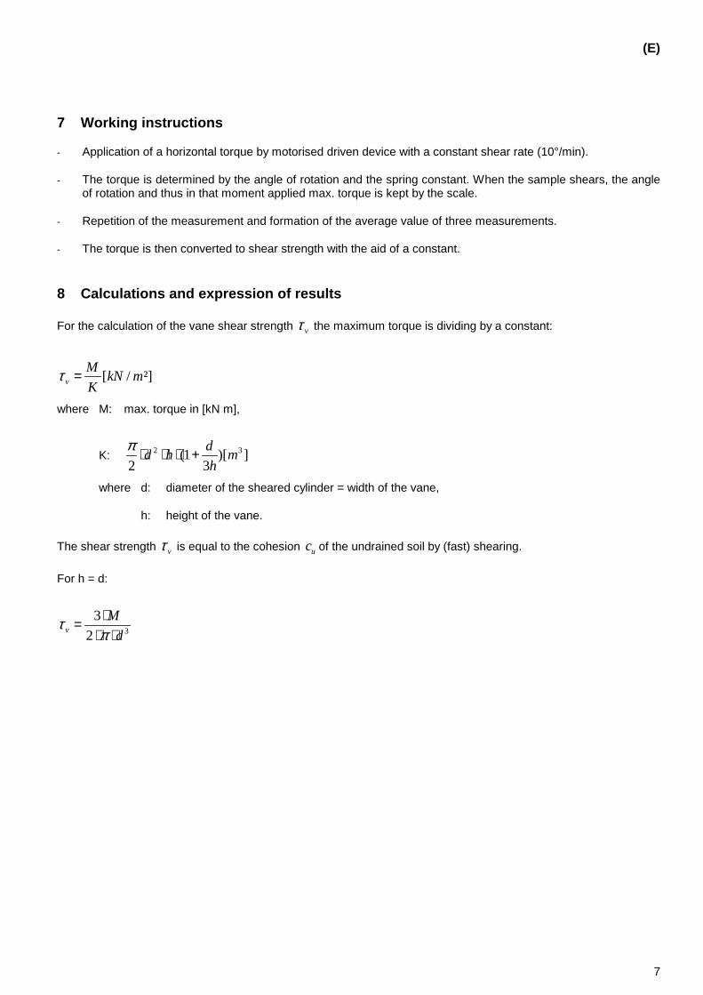
(E)
7
7 Working instructions
- Application of a horizontal torque by motorised driven device with a constant shear rate (10°/min).
- The torque is determined by the angle of rotation and the spring constant. When the sample shears, the angle of rotation and thus in that moment applied max. torque is kept by the scale.
- Repetition of the measurement and formation of the average value of three measurements.
- The torque is then converted to shear strength with the aid of a constant.
8 Calculations and expression of results
For the calculation of the vane shear strength vτ the maximum torque is dividing by a constant:
[ / ²]vM kN mK
τ =
where M: max. torque in [kN m],
K: 2 3(1 )[ ]2 3
dd h mh
π ⋅ ⋅ ⋅ +
where d: diameter of the sheared cylinder = width of the vane,
h: height of the vane.
The shear strength vτ is equal to the cohesion uc of the undrained soil by (fast) shearing.
For h = d:
3
32v
Md
τπ⋅=
⋅ ⋅

(E)
8
9 Test report
The test report shall include the following informations:
a) The standard under consideration and its date of publication (e.g. EN xxxx:2003)
b) Information about the character of the material and the identity of the specific sample(s) to be tested
c) Testing date or period
d) Information on external circumstances
e) All calculation results
f) Identification of the standards used in the total test procedure
g) Optionally: The test results obtained by field test
h) Always finish the report with: ‘Where the test is not carried out in accordance with this standard, reference may only be made to EN xxxx:2003 in the report in case all deviations from the procedures prescribed in this standard are indicated in the report stating the reasons for deviation'.

(E)
9
Annex A (informative)
Laboratory vane shear apparatus
Figure A.1 — Laboratory vane shear apparatus [1]

(E)
10
Bibliography
[1] ATV-Arbeitsbericht: Die Bestimmung der Deponierfähigkeit von Schlämmen mit der Referenzmethode „Laborflügelscherfestigkeit“, ATV-Fachausschuss 3.2 und 3.6, Gesellschaft zur Förderung der Abwassertechnik e.V. (GFA), 53773 Hennef: Korrespondenz Abwasser (1989), 36 (8), S. 903-909
[2] DIN 18127 (1997): Proctorversuch, Beuth-Verlag, Berlin
[3]
[4]

70 HORIZONTAL – Report No. 22
ANNEX 3

Document type: European Standard Document subtype: Document stage: CEN Enquiry Document language: E
HORIZONTAL – Report No. 22 (Annex 3) Date:
CEN
Secretariat:
Physical properties – Determination of solidity – "Shear strength": Laboratory reference method by 'Penetrometer' Physikalische Eigenschaften – Bestimmung der Festigkeit – Scherfestigkeit": Laborreferenzmethode mit dem 'Penetrometer'
Propriétés […] – Détermination de la […] – Partie 1: […]
ICS:
Descriptors:

(E)
2
Contents
Foreword......................................................................................................................................................................3 Introduction .................................................................................................................................................................4 1 Scope ..............................................................................................................................................................5 2 Standards and other normative references ................................................................................................5 3 Terms and definitions ...................................................................................................................................6 4 Principle..........................................................................................................................................................6 5 Equipment ......................................................................................................................................................6 5.1 Penetrometer..................................................................................................................................................6 5.1.1 Carrier .............................................................................................................................................................6 5.1.2 Cone tips.........................................................................................................................................................6 6 Test sample(s)................................................................................................................................................6 7 Working instructions.....................................................................................................................................7 8 Calculations and expression of results.......................................................................................................7 9 Test report ......................................................................................................................................................8 Annex A (informative) Penetrometer .........................................................................................................................9 Bibliography ..............................................................................................................................................................10

(E)
3
Foreword
This document has been prepared by HORIZONTAL-Committee // CEN /TC /…, " […]".
This document is currently submitted to the HORIZONTAL Enquiry.
Other parts of this European Standard /HORIZONTAL Standards – Physical Properties are:
[…] - Determination of bulk density;
[…] - Determination of dry matter;
[…] - Determination of thixotropic behaviour;
[…] - Determination of piling behaviour;
[…] - Determination of flowability

(E)
4
Introduction
This document is developed in the project 'Horizontal'. It is the result of desk study "Physical properties – Solidity, Thixotropic Behaviour and Piling Behaviour" in the project and aims at a laboratory reference method for determining the solidity of sludge, soil, bio-waste and related wastes by means of the penetrometer. After discussion with all parties concerned in CEN and selection of a number of test methods described in this study will be developed further as an modular horizontal method and validated in the project 'Horizontal'.
Until now test methods determining properties of materials were often prepared in Technical Committees (TC's) working on specific products or specific sectors. In those test methods often steps as sampling, extraction, release or other processing, analyses, etc were included. In this approach it was necessary to develop, edit and validate similar procedural steps over and over again for each other product. Consequently this resulted in a lot of duplicate work. To avoid such duplication of work for parts of a testing procedure often was referred to parts of test methods from other TC's. However following problems are often encountered while using references in this way:
1) The referenced parts are often not edited in a way that they could easily be referred to, 2) the referenced parts are often not validated for the other type of material and 3) the updates of such test standards on products might lead to inadequate references.
In the growing amount of product and sector oriented test methods it was recognised that many steps in test procedures are or could be used in test procedures for many products, materials and sectors. It was supposed that, by careful determination of these steps and selection of specific questions within these steps, elements of the test procedure could be described in a way that they can be used for all materials and products or for all materials and products with certain specifications.
Based on this hypothesis a horizontal modular approach is being investigated and developed in the project 'Horizontal'. 'Horizontal' means that the methods can be used for a wide range of materials and products with certain properties. 'Modular' means that a test standard developed in this approach concerns a specific step in a test procedure and not the whole test procedure.
The texts of the chapters [x,x, and x] are normative; chapter [x, x] are informative chapters; annexes are normative or informative, as stated in the top lines of the annexes.

(E)
5
1 Scope
This Part of this European standard specifies a laboratory reference method for determining the parameter shear strength of sludge, soil, bio-waste and related wastes by means of the penetrometer.
This Part of this European Standard is applicable to sludge, soil, bio-waste and related wastes from:
storm water handling
urban wastewater collecting systems
urban wastewater treatment plants
treating industrial wastewater similar to urban wastewater (as defined in Directive 91/271/EEC)
water supply treatment plants
soil
bio-waste (OFMSW, compost, etc. …).
This method is also applicable to sludge, soil, bio-waste and related wastes of other origin.
2 Standards and other normative references
This European Standard incorporates by dated or undated reference, provisions from other publications. These normative references are cited at the appropriate places in the text and the publications are listed hereafter. For dated references, subsequent amendments to or revisions of any of these publications apply to this European Standard only when incorporated in it by amendment or revision. For undated references the latest edition of the publication referred to applies (including amendments).
ISO 2137 — […]
ASTM D217
ASTM D937
BS 2000-49
BS 3712
prEN 13880-2
DIN 51580
DIN EN 1426
ISO/DIS 13765-1
Other Horizontal Standards:
[…], Sampling (in-situ and during transport) — […]
[…], Sample pre-treatment — […]
[…], Composition — Inorganic constituents — […]
[…], Composition — Organic constituents — […]

(E)
6
[…], Hygienic parameters — […]
[…], Biological parameters — […]
[…], Leaching — […]
[…], Vocabulary — […]
3 Terms and definitions
For the purposes of this Part of this European Standard, the terms and definitions as stated in […], Vocabulary — […] and the following terms and definitions apply.
4 Principle
For determining the undrained shear strength uc with the penetrometer the depth - in tenth of a millimetre -, which the needle or cone (in part several cone tips of different sizes) penetrates the sample under specific conditions of weight of the cone and time, is measured.
The undrained shear strength uc is then calculated by the weight of the cone, the penetration depth and the constant K.
5 Equipment
5.1 Penetrometer
5.1.1 Carrier
5.1.2 Cone tips
6 Test sample(s)
For the pre-treatment for measuring the shear strength the steps have to be taken as follows:
(1) The material – if needed, dewatered – is reduced to small pieces with particle sizes of about 10 mm
(2) The mould – in this case the small Proctor vessel – has an internal diameter of 100 mm und a height of 120 mm.
(3) The material is filled into the Proctor vessel in three equal portions (each about 100 mm before compaction) and is compressed with ten knocks by the small Proctor hammer (falling weight of 2.5 kg, height of falling 300 mm, diameter of the plunger 50 mm, diameter of compensating plate 99,5 mm, compare DIN 18127 Proctor test [2]).
(4) After finishing emplacement and before test performance the density have to determined for a uniform starting position (Proctor density)

(E)
7
7 Working instructions
- Contact the tip of the penetrometer with the surface of the sample (h = 0) and then release the cone or needle.
- After a fixed duration of 5s the depth, which is penetrated by the cone tip or needle, is measured. According to the consistency of the analysed material several cone tips or needles of different sizes and weights (150mg – 150g) have to be used.
- The temperature during the measurements should be 25 C.
- Repetition of the measurement and formation of the average value of three measurements.
- The undrained shear strength uc is then calculated by the weight of the cone, the penetration depth and the constant K.
8 Calculations and expression of results
The undrained shear strength uc is calculated by the weight of the cone, the penetration depth and the constant K:
2 1uK m g hc
i i⋅ ⋅ = ⋅ +
where m: mass of the cone,
g: acceleration of gravity,
i: depth of penetration (indentation),
h: distance between cone apex and soil surface when the cone is dropped (normally h = 0),
K: function of the apex angle of the cone (Fig. 1).
Fig. 1: Relation between the parameter K and the apex angle bbbb of the cone

(E)
8
9 Test report
The test report shall include the following informations:
a) The standard under consideration and its date of publication (e.g. EN xxxx:2003)
b) Information about the character of the material and the identity of the specific sample(s) to be tested
c) Testing date or period
d) Information on external circumstances
e) All calculation results
f) Identification of the standards used in the total test procedure
g) Optionally: The test results obtained by field test
h) Always finish the report with: ‘Where the test is not carried out in accordance with this standard, reference may only be made to EN xxxx:2003 in the report in case all deviations from the procedures prescribed in this standard are indicated in the report stating the reasons for deviation'.

(E)
9
Annex A (informative)
Penetrometer
Figure A.1 — Penetrometer

(E)
10
Bibliography
[1] Hansbo, S. (1994): Foundation Engineering, Developments in Geotechnical Engineering, 75, Elsevier
[2] DIN 18127 (1997): Proctorversuch, Beuth-Verlag, Berlin
[3]

HORIZONTAL – Report No. 22 71
ANNEX 4

72 HORIZONTAL – Report No. 22
ANNEX 5

HORIZONTAL – Report No. 22 73
ANNEX 6

74 HORIZONTAL – Report No. 22
ANNEX 7

HORIZONTAL – Report No. 22 75
ANNEX 8

76 HORIZONTAL – Report No. 22
ANNEX 9

HORIZONTAL – Report No. 22 77
ANNEX 10

Document type: European Standard Document subtype: Document stage: CEN Enquiry Document language: E
HORIZONTAL – Report No. 22 (Annex 10) Date:
CEN
Secretariat:
Physical properties – Determination of piling behaviour – "Piling angle": Laboratory reference method by 'Cubic Piling Box (CPB)' Physikalische Eigenschaften – Bestimmung des Schüttverhaltens – "Schüttwinkel": Laborreferenzmethode mit dem 'kubischen Schüttkasten'
Propriétés […] – Détermination de la […] – […]
ICS:
Descriptors:

(E)
2
Contents
Foreword......................................................................................................................................................................3 Introduction .................................................................................................................................................................4 1 Scope ..............................................................................................................................................................5 2 Standards and other normative references ................................................................................................5 3 Terms and definitions ...................................................................................................................................6 4 Principle..........................................................................................................................................................6 5 Equipment ......................................................................................................................................................6 5.1 Cubic Piling Box (CPB) .................................................................................................................................6 6 Test sample(s)................................................................................................................................................6 7 Working instructions.....................................................................................................................................7 8 Calculations and expression of results.......................................................................................................7 9 Test report ......................................................................................................................................................7 Annex A (informative) Cubic Piling Box (CPB).......................................................................................................8 Bibliography ................................................................................................................................................................9

(E)
3
Foreword
This document has been prepared by HORIZONTAL-Committee // CEN /TC /…, " […]".
This document is currently submitted to the HORIZONTAL Enquiry.
Other parts of this European Standard /HORIZONTAL Standards – Physical Properties are:
[…] - Determination of bulk density;
[…] - Determination of dry matter;
[…] - Determination of solidity;
[…] - Determination of thixotropic behaviour;
[…] - Determination of flowability

(E)
4
Introduction
This document is developed in the project 'Horizontal'. It is the result of desk study "Physical properties – Solidity, Thixotropic Behaviour and Piling Behaviour" in the project and aims at a laboratory reference method for determining the piling behaviour of sludge, soil, bio-waste and related wastes by means of the Cubic Piling Box (CPB). After discussion with all parties concerned in CEN and selection of a number of test methods described in this study will be developed further as an modular horizontal method and validated in the project 'Horizontal'.
Until now test methods determining properties of materials were often prepared in Technical Committees (TC's) working on specific products or specific sectors. In those test methods often steps as sampling, extraction, release or other processing, analyses, etc were included. In this approach it was necessary to develop, edit and validate similar procedural steps over and over again for each other product. Consequently this resulted in a lot of duplicate work. To avoid such duplication of work for parts of a testing procedure often was referred to parts of test methods from other TC's. However following problems are often encountered while using references in this way:
1) The referenced parts are often not edited in a way that they could easily be referred to, 2) the referenced parts are often not validated for the other type of material and 3) the updates of such test standards on products might lead to inadequate references.
In the growing amount of product and sector oriented test methods it was recognised that many steps in test procedures are or could be used in test procedures for many products, materials and sectors. It was supposed that, by careful determination of these steps and selection of specific questions within these steps, elements of the test procedure could be described in a way that they can be used for all materials and products or for all materials and products with certain specifications.
Based on this hypothesis a horizontal modular approach is being investigated and developed in the project 'Horizontal'. 'Horizontal' means that the methods can be used for a wide range of materials and products with certain properties. 'Modular' means that a test standard developed in this approach concerns a specific step in a test procedure and not the whole test procedure.
The texts of the chapters [x,x, and x] are normative; chapter [x, x] are informative chapters; annexes are normative or informative, as stated in the top lines of the annexes.

(E)
5
1 Scope
This Part of this European standard specifies a laboratory reference method for determining the parameter piling angle of sludge, soil, bio-waste and related wastes by means of the Cubic Piling Box (CPB).
This Part of this European Standard is applicable to sludge, soil, bio-waste and related wastes from:
storm water handling
urban wastewater collecting systems
urban wastewater treatment plants
treating industrial wastewater similar to urban wastewater (as defined in Directive 91/271/EEC)
water supply treatment plants
soil
bio-waste (OFMSW, compost, etc. …)
This method is also applicable to sludge, soil, bio-waste and related wastes of other origin.
2 Standards and other normative references
This European Standard incorporates by dated or undated reference, provisions from other publications. These normative references are cited at the appropriate places in the text and the publications are listed hereafter. For dated references, subsequent amendments to or revisions of any of these publications apply to this European Standard only when incorporated in it by amendment or revision. For undated references the latest edition of the publication referred to applies (including amendments).
[…] — […]
Other Horizontal Standards:
[…], Sampling (in-situ and during transport) — […]
[…], Sample pre-treatment — […]
[…], Composition — Inorganic constituents — […]
[…], Composition — Organic constituents — […]
[…], Hygienic parameters — […]
[…], Biological parameters — […]
[…], Leaching — […]
[…], Vocabulary — […]
[…] — […]

(E)
6
3 Terms and definitions
For the purposes of this Part of this European Standard, the terms and definitions as stated in […] and the following terms and definitions apply.
Slope angle Inclination of a slope referring to horizontal (i.e. angle at the toe). Piling angle Slope angle of a material at rest.
4 Principle
This method can be used for determining the piling angle (angle of rest) of loose materials.
After placing the material into the box, the sidewalls are suddenly overturned and the stable final configuration is surveyed. The natural slope angle of the remaining material can be measured on each side of the sample remaining on the box base.
The CPB can be used to immediately and easily assess the natural slope angle of a material.
The influence of the CPB dimension on the slope angle should be negligible provided that the side of the box is much greater than the maximum grain size of the sample.
Important advantages of this method are that it is very simple, easy to do both in the laboratory and in the field and that no specialised personnel is requested.
5 Equipment
5.1 Cubic Piling Box (CPB)
5.1.1 A cubic box made of corrosion resistant material, without the upper side (see Figure A.1). The sidewalls must be overturn able so that the material inside can freely fall down (see Figure A.2).
5.1.2 A rigid support must be provided under the box in order to let the sidewalls overturn almost completely (see Figure A.2).
5.1.3 A device to measure the slope angle. To this purpose a total topographical station is the best way to have precise measurements and automatic data acquisition.
6 Test sample(s)
The CPB test can be easily performed on loose materials (soils, waste, etc.) as well as on cohesive materials (e.g. compacted materials).
This method was proposed for solid waste materials having a maximum grain size of about 5 cm [1] . In that case, the sides of the cubic box were equal to 60 cm.
The minimum dimensions of the cubic box can be related to the grain size of the material to be tested. A minimum of 30 cm x 30 cm should be considered in order to test a representative volume of material.

(E)
7
7 Working instructions
The material to be tested can be placed into the box by pouring it or it can be placed in layers that can be compacted according to procedures similar to the Standard Proctor procedure [2].
If poured, the material must be left for at least 24 hours in order to let it consolidate under self-weight.
Then the sidewalls are suddenly overturned and the stable final configuration is surveyed.
The natural slope angle of the remaining material can be measured on each side of the sample remaining on the box base.
8 Calculations and expression of results
If the material is homogeneous, the slope will have the same angle. This is the angle to be measured.
In case of non-homogeneous material, each of the four angles must be measured and all the values must be expressed as results.
9 Test report
The test report shall include the following informations:
a) The standard under consideration and its date of publication (e.g. EN xxxx:2003)
b) Information about the character of the material and the identity of the specific sample(s) to be tested
c) Testing date or period
d) Information on external circumstances
e) All calculation results
f) Identification of the standards used in the total test procedure
g) The test results obtained by field test
h) Always finish the report with: ‘Where the test is not carried out in accordance with this standard, reference may only be made to EN xxxx:2003 in the report in case all deviations from the procedures prescribed in this standard are indicated in the report stating the reasons for deviation'.

(E)
8
base
hing
sidewall
Annex A (informative)
Cubic Piling Box (CPB)
Figure A.1 — Cubic Piling Box (CPB); closed sidewalls []
Figure A.2 — Cubic Piling Box (CPB); open sidewalls []

(E)
9
Bibliography
[1] Pasqualini E., Patacchini C., Stella M. (2003) Mechanical characterisation of municipal solid waste (in Italian). Proc. Annual Meeting of the Researchers in Geotechnics, IARG 2003.
[2] ASTM D698-91. Test method for laboratory compaction characteristics of soil using standard effort. ASTM Standards, Volume 04.08 Soil and Rock (I).

78 HORIZONTAL – Report No. 22
ANNEX 11

Document type: European Standard Document subtype: Document stage: CEN Enquiry Document language: E
HORIZONTAL – Report No. 22 (Annex 11) Date:
CEN
Secretariat:
Physical properties – Determination of piling behaviour – "Compactibility": Laboratory reference method by 'Oedometer test' Physikalische Eigenschaften – Bestimmung des Schüttverhaltens – "Verdichtbarkeit": Laborreferenzmethode mit dem 'Oedometer Test'
Propriétés […] – Détermination de la […] – […]
ICS:
Descriptors:

(E)
2
Contents
Foreword......................................................................................................................................................................3 Introduction .................................................................................................................................................................4 1 Scope ..............................................................................................................................................................5 2 Standards and other normative references ................................................................................................5 3 Terms and definitions ...................................................................................................................................6 4 Principle..........................................................................................................................................................6 5 Equipment ......................................................................................................................................................6 5.1 Oedometer ......................................................................................................................................................6 6 Test sample(s)................................................................................................................................................6 7 Working instructions.....................................................................................................................................7 8 Calculations and expression of results.......................................................................................................7 9 Test report ......................................................................................................................................................7 Annex A (informative) Oedometer ...........................................................................................................................8 Bibliography ..............................................................................................................................................................10

(E)
3
Foreword
This document has been prepared by HORIZONTAL-Committee // CEN /TC /…, " […]".
This document is currently submitted to the HORIZONTAL Enquiry.
Other parts of this European Standard /HORIZONTAL Standards – Physical Properties are:
[…] - Determination of bulk density;
[…] - Determination of dry matter;
[…] - Determination of solidity;
[…] - Determination of thixotropic behaviour;
[…] - Determination of flowability

(E)
4
Introduction
This document is developed in the project 'Horizontal'. It is the result of desk study "Physical properties – Solidity, Thixotropic Behaviour and Piling Behaviour" in the project and aims at a laboratory reference method for determining the piling behaviour of sludge, soil, bio-waste and related wastes by means of the Oedometer test. After discussion with all parties concerned in CEN and selection of a number of test methods described in this study will be developed further as an modular horizontal method and validated in the project 'Horizontal'.
Until now test methods determining properties of materials were often prepared in Technical Committees (TC's) working on specific products or specific sectors. In those test methods often steps as sampling, extraction, release or other processing, analyses, etc were included. In this approach it was necessary to develop, edit and validate similar procedural steps over and over again for each other product. Consequently this resulted in a lot of duplicate work. To avoid such duplication of work for parts of a testing procedure often was referred to parts of test methods from other TC's. However following problems are often encountered while using references in this way:
1) The referenced parts are often not edited in a way that they could easily be referred to, 2) the referenced parts are often not validated for the other type of material and 3) the updates of such test standards on products might lead to inadequate references.
In the growing amount of product and sector oriented test methods it was recognised that many steps in test procedures are or could be used in test procedures for many products, materials and sectors. It was supposed that, by careful determination of these steps and selection of specific questions within these steps, elements of the test procedure could be described in a way that they can be used for all materials and products or for all materials and products with certain specifications.
Based on this hypothesis a horizontal modular approach is being investigated and developed in the project 'Horizontal'. 'Horizontal' means that the methods can be used for a wide range of materials and products with certain properties. 'Modular' means that a test standard developed in this approach concerns a specific step in a test procedure and not the whole test procedure.
The texts of the chapters [x,x, and x] are normative; chapter [x, x] are informative chapters; annexes are normative or informative, as stated in the top lines of the annexes.

(E)
5
1 Scope
This Part of this European standard specifies a laboratory reference method for determining the parameter compactibility of sludge, soil, bio-waste and related wastes by means of the Oedometer test.
This Part of this European Standard is applicable to sludge, soil, bio-waste and related wastes from:
storm water handling
urban wastewater collecting systems
urban wastewater treatment plants
treating industrial wastewater similar to urban wastewater (as defined in Directive 91/271/EEC)
water supply treatment plants
soil
bio-waste (OFMSW, compost, etc. …)
This method is also applicable to sludge, soil, bio-waste and related wastes of other origin.
2 Standards and other normative references
This European Standard incorporates by dated or undated reference, provisions from other publications. These normative references are cited at the appropriate places in the text and the publications are listed hereafter. For dated references, subsequent amendments to or revisions of any of these publications apply to this European Standard only when incorporated in it by amendment or revision. For undated references the latest edition of the publication referred to applies (including amendments).
ASTM D2435 — Standard test method for one-dimensional consolidation properties of soils
XP P94-091 — Soil : investigation and testing. Swelling test with oedometer. Determination of deformations by loading several test pieces.
Other Horizontal Standards:
[…], Sampling (in-situ and during transport) — […]
[…], Sample pre-treatment — […]
[…], Composition — Inorganic constituents — […]
[…], Composition — Organic constituents — […]
[…], Hygienic parameters — […]
[…], Biological parameters — […]
[…], Leaching — […]
[…], Vocabulary — […]
[…] — […]

(E)
6
3 Terms and definitions
For the purposes of this Part of this European Standard, the terms and definitions as stated in […] and the following terms and definitions apply.
Compressibility Property of a material pertaining to its susceptibility to decrease in volume when subjected to load.
4 Principle
The oedometer test can be used to characterize the compressibility of the material and to have an indication of how much a stratum of piled material can settle due to the loading of the material placed above.
For piling behaviour, the selection of the loading schedule (maximum value, load increments and the duration of each increment) will be defined on the basis of the total height of piling and of the piling sequence. In particular, the maximun load will be necessarily lower than that used according to the standard for soils [1].
The straining condition of a material due to piling are different from those in the oedometer, where lateral strains are prevented. Nevertheless, if the material is piled in lifts that are large enough in comparison with their height (three times at least), oedometic strains can be considered as representative. Settlements of the lower portion of the material can be evaluated.
Important advantages of this method are that the procedure is well known and it is easy to do.
5 Equipment
5.1 Oedometer
5.1.1 A cylindrical mould containing the sample (see Figure A.1), that is placed on a porous disk
5.1.2 A porous disk placed upon the sample (see Figure A.2.), having a diameter 0.2 to 0.5 mm less than the inside diameter of the mould.
5.1.3 Both porous disks shall be fine enough to prevent intrusion of material into the pores; their permeability must be at least one order of magnitude higher that that of the sample.
5.1.4 A device for applying vertical loads or total stresses; it should permit quick application of a given load increment without significant impact (see Figure A.3)
5.1.5 A deformation indicator, to measure changes in sample height, with a readability of 2 µm.
6 Test sample(s)
This method is most commonly performed on undisturbed samples of fine grained soils naturally sedimented in water [1]; the basic test procedure can be also applicable to residual (weathered or chemically altered) soils or to specimens of compacted materials.
The sample is restrained laterally and loaded axially with vertical stress increments. No horizontal deformation of the sample is permitted but only a vertical strain. The size of the mold that contains the specimen can vary on the basis of the maximum grain size of the material to be tested. Minimum specimen diameter and height should be 20 cm in order to test a representative volume of material. The minimum specimen diameter to height ratio shall be 2.5 in order to avoid significant influence of the friction along the lateral surface between the sample and the mould.

(E)
7
7 Working instructions
The inner surface of the mould shall be highly polished or shall be coated with a low friction material (e.g. silicone grease)
The material must be placed into the mould and then a prefixed sequence of loads must be applied.
The material can be compacted into the mould (for example according to the standard Proctor procedure [2]) or it can be simply poured, depending on its nature.
Each load must be placed suddenly and left on the specimen for 24 hours in order to let it consolidate completely.
8 Calculations and expression of results
Vertical deformations must be measured for each load increment. The vertical deformation for a given load is calculated referring to the height of the specimen at the previous load.
Vertical deformations must be plotted versus vertical pressures in order to obtain the compression curve of the material. For each load increment the Young modulus can be calculated as the ratio between the current vertical pressure increment and axial deformation.
9 Test report
The test report shall include the following informations:
a) The standard under consideration and its date of publication (e.g. EN xxxx:2003)
b) Information about the character of the material and the identity of the specific sample(s) to be tested
c) Testing date or period
d) Information on external circumstances
e) All calculation results
f) Identification of the standards used in the total test procedure
g) The test results obtained by field test
h) Always finish the report with: ‘Where the test is not carried out in accordance with this standard, reference may only be made to EN xxxx:2003 in the report in case all deviations from the procedures prescribed in this standard are indicated in the report stating the reasons for deviation'.

(E)
8
Annex A (informative)
Oedometer
Figure A.1 — Cylindrical mould
Figure A.2 — Oedometer
porous disk
porous disk
rigid mould
load
cap
Sample
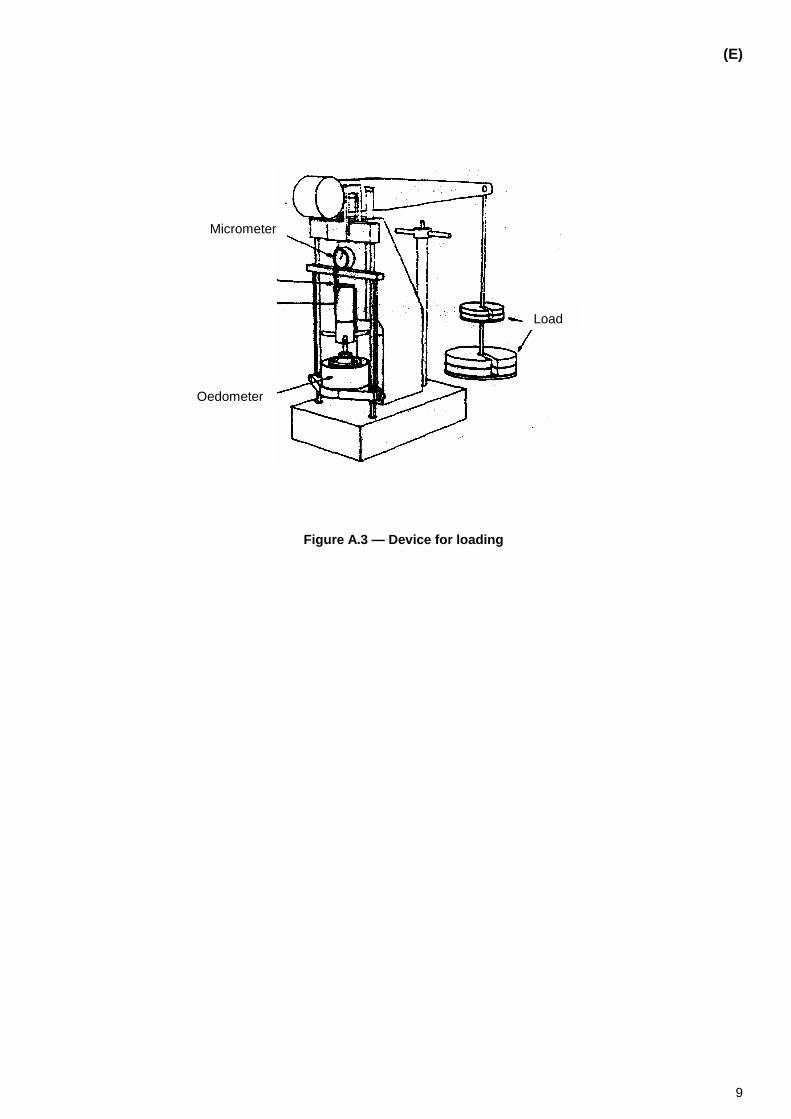
(E)
9
Figure A.3 — Device for loading
Micrometer
Oedometer
Load

(E)
10
Bibliography
[1] ASTM D2435-96. Standard test method for one-dimensional consolidation properties of soils. ASTM Standards, Volume 04.08 Soil and Rock (I).
[2] ASTM D698-91. Test method for laboratory compaction characteristics of soil using standard effort. ASTM Standards, Volume 04.08 Soil and Rock (I).
[3]
[4]

HORIZONTAL – Report No. 22 79
ANNEX 12

Document type: European Standard Document subtype: Document stage: CEN Enquiry Document language: E
HORIZONTAL – Report No. 22 (Annex 12) Date:
CEN
Secretariat:
Physical properties – Determination of piling behaviour – "Piling angle": Field test by 'Cubic Piling Box (CPB)' Physikalische Eigenschaften – Bestimmung des Schüttverhaltens – "Schüttwinkel": Felduntersuchung mit dem 'kubischen Schüttkasten'
Propriétés […] – Détermination de la […] – […]
ICS:
Descriptors:

(E)
2
Contents
Foreword......................................................................................................................................................................3 Introduction .................................................................................................................................................................4 1 Scope ..............................................................................................................................................................5 2 Standards and other normative references ................................................................................................5 3 Terms and definitions ...................................................................................................................................6 4 Principle..........................................................................................................................................................6 5 Equipment ......................................................................................................................................................6 5.1 Cubic Piling Box (CPB) .................................................................................................................................6 6 Test sample(s)................................................................................................................................................6 7 Working instructions.....................................................................................................................................7 8 Calculations and expression of results.......................................................................................................7 9 Test report ......................................................................................................................................................7 Annex A (informative) Cubic Piling Box (CPB).......................................................................................................8 Bibliography ................................................................................................................................................................9

(E)
3
Foreword
This document has been prepared by HORIZONTAL-Committee // CEN /TC /…, " […]".
This document is currently submitted to the HORIZONTAL Enquiry.
Other parts of this European Standard /HORIZONTAL Standards – Physical Properties are:
[…] - Determination of bulk density;
[…] - Determination of dry matter;
[…] - Determination of solidity;
[…] - Determination of thixotropic behaviour;
[…] - Determination of flowability
(E)
4
Introduction
This document is developed in the project 'Horizontal'. It is the result of desk study "Physical properties – Solidity, Thixotropic Behaviour and Piling Behaviour" in the project and aims at a field test for determining the piling behaviour of sludge, soil, bio-waste and related wastes by means of the Cubic Piling Box (CPB). After discussion with all parties concerned in CEN and selection of a number of test methods described in this study will be developed further as an modular horizontal method and validated in the project 'Horizontal'.
Until now test methods determining properties of materials were often prepared in Technical Committees (TC's) working on specific products or specific sectors. In those test methods often steps as sampling, extraction, release or other processing, analyses, etc were included. In this approach it was necessary to develop, edit and validate similar procedural steps over and over again for each other product. Consequently this resulted in a lot of duplicate work. To avoid such duplication of work for parts of a testing procedure often was referred to parts of test methods from other TC's. However following problems are often encountered while using references in this way:
1) The referenced parts are often not edited in a way that they could easily be referred to, 2) the referenced parts are often not validated for the other type of material and 3) the updates of such test standards on products might lead to inadequate references.
In the growing amount of product and sector oriented test methods it was recognised that many steps in test procedures are or could be used in test procedures for many products, materials and sectors. It was supposed that, by careful determination of these steps and selection of specific questions within these steps, elements of the test procedure could be described in a way that they can be used for all materials and products or for all materials and products with certain specifications.
Based on this hypothesis a horizontal modular approach is being investigated and developed in the project 'Horizontal'. 'Horizontal' means that the methods can be used for a wide range of materials and products with certain properties. 'Modular' means that a test standard developed in this approach concerns a specific step in a test procedure and not the whole test procedure.
The texts of the chapters [x,x, and x] are normative; chapter [x, x] are informative chapters; annexes are normative or informative, as stated in the top lines of the annexes.

(E)
5
1 Scope
This Part of this European standard specifies a field test for determining the parameter piling angle of sludge, soil, bio-waste and related wastes by means of the Cubic Piling Box (CPB).
This Part of this European Standard is applicable to sludge, soil, bio-waste and related wastes from:
storm water handling
urban wastewater collecting systems
urban wastewater treatment plants
treating industrial wastewater similar to urban wastewater (as defined in Directive 91/271/EEC)
water supply treatment plants
soil
bio-waste (OFMSW, compost, etc. …)
This method is also applicable to sludge, soil, bio-waste and related wastes of other origin.
2 Standards and other normative references
This European Standard incorporates by dated or undated reference, provisions from other publications. These normative references are cited at the appropriate places in the text and the publications are listed hereafter. For dated references, subsequent amendments to or revisions of any of these publications apply to this European Standard only when incorporated in it by amendment or revision. For undated references the latest edition of the publication referred to applies (including amendments).
[…] — […]
Other Horizontal Standards:
[…], Sampling (in-situ and during transport) — […]
[…], Sample pre-treatment — […]
[…], Composition — Inorganic constituents — […]
[…], Composition — Organic constituents — […]
[…], Hygienic parameters — […]
[…], Biological parameters — […]
[…], Leaching — […]
[…], Vocabulary — […]
[…] — […]

(E)
6
3 Terms and definitions
For the purposes of this Part of this European Standard, the terms and definitions as stated in […] and the following terms and definitions apply.
Slope angle Inclination of a slope referring to horizontal (i.e. angle at the toe). Piling angle Slope angle of a material at rest.
4 Principle
This method can be used for determining the piling angle (angle of rest) of loose materials.
After placing the material into the box, the sidewalls are suddenly overturned and the stable final configuration is surveyed. The natural slope angle of the remaining material can be measured on each side of the sample remaining on the box base.
The CPB can be used to immediately and easily assess the natural slope angle of a material.
The influence of the CPB dimension on the slope angle should be negligible provided that the side of the box is much greater than the maximum grain size of the sample.
Important advantages of this method are that it is very simple, easy to do both in the laboratory and in the field and that no specialised personnel is requested.
5 Equipment
5.1 Cubic Piling Box (CPB)
5.1.1 A cubic box made of corrosion resistant material, without the upper side (see Figure A.1). The sidewalls must be overturn able so that the material inside can freely fall down (see Figure A.2).
5.1.2 A rigid support must be provided under the box in order to let the sidewalls overturn almost completely (see Figure A.2).
5.1.3 A device to measure the slope angle. To this purpose a total topographical station is the best way to have precise measurements and automatic data acquisition.
6 Test sample(s)
The CPB test can be easily performed on loose materials (soils, waste, etc.) as well as on cohesive materials (e.g. compacted materials).
This method was proposed for solid waste materials having a maximum grain size of about 5 cm [1] . In that case, the sides of the cubic box were equal to 60 cm.
The minimum dimensions of the cubic box can be related to the grain size of the material to be tested. A minimum of 30 cm x 30 cm should be considered in order to test a representative volume of material.

(E)
7
7 Working instructions
The material to be tested can be placed into the box by pouring it or it can be placed in layers that can be compacted according to procedures similar to the Standard Proctor procedure [2].
If poured, the material must be left for at least 24 hours in order to let it consolidate under self-weight.
Then the sidewalls are suddenly overturned and the stable final configuration is surveyed.
The natural slope angle of the remaining material can be measured on each side of the sample remaining on the box base.
8 Calculations and expression of results
If the material is homogeneous, the slope will have the same angle. This is the angle to be measured.
In case of non-homogeneous material, each of the four angles must be measured and all the values must be expressed as results.
9 Test report
The test report shall include the following informations:
a) The standard under consideration and its date of publication (e.g. EN xxxx:2003)
b) Information about the character of the material and the identity of the specific sample(s) to be tested
c) Testing date or period
d) Information on external circumstances
e) All calculation results
f) Identification of the standards used in the total test procedure
g) The test results obtained by laboratory reference method
h) Always finish the report with: ‘Where the test is not carried out in accordance with this standard, reference may only be made to EN xxxx:2003 in the report in case all deviations from the procedures prescribed in this standard are indicated in the report stating the reasons for deviation'.

(E)
8
base
hing
sidewall
Annex A (informative)
Cubic Piling Box (CPB)
Figure A.1 — Cubic Piling Box (CPB); closed sidewalls [1]
Figure A.2 — Cubic Piling Box (CPB); open sidewalls [1]

(E)
9
Bibliography
[1] Pasqualini E., Patacchini C., Stella M. (2003) Mechanical characterisation of municipal solid waste (in Italian). Proc. Annual Meeting of the Researchers in Geotechnics, IARG 2003.
[2] ASTM D698-91. Test method for laboratory compaction characteristics of soil using standard effort. ASTM Standards, Volume 04.08 Soil and Rock (I).

80 HORIZONTAL – Report No. 22
ANNEX 13
Cover Letter 1.Aug. 2003

Postanschrift Telefon E-mail D - 21071 Hamburg ++49 (40) 428 78-3917 [email protected] Besucheranschrift Fax Schwarzenbergstraße 95 ++49 (40) 428 78-2999 21073 Hamburg www.tu-harburg.de
Hamburg, 01.08.03 Th
Horizontal WP 7 "Physical Parameters" 1. Draft Report of Desk Study No. 22 "Solidity, Thixotropic Behaviour and Piling Behaviour" Dear all, in the annex "HorizontalNo22_010803.pdf" , "annex1_010803.pdf" and "annex2_010803.pdf" you will find the first draft of our desktop study report on "Solidity, Thixotropic Behaviour and Piling Behaviour". Please give us your comments until Wednesday, 20. August 2003 by email to below address. All the comments received will be discussed at the Hamburg meeting of CEN/TC308/WG1/TG3 on 28.08.03 and of CEN/TC308/WG1 on 29.08.03. The final version will be prepared at the end of the WG1 meeting in order to be sending to the coordinators on HORIZONTAL by 31. August 03 (absolute deadline). Many thanks for your cooperation. Kind regards, K. Wichmann / C. Thormählen
CEN/TC308/WG1 CEN/TC308/WG1/TG3 M. Aldo Giove
ARBEITSBEREICHWASSERWIRTSCHAFT UND
WASSERVERSORGUNG
PROF. DR.-ING. KNUT WICHMANN
TUHH Wasserwirtschaft D-21071 Hamburg

HORIZONTAL – Report No. 22 81
ANNEX 14
Comments received and commented

Date: 2003-09-01 CEN, ISO, NSB, MS and AS enquiry on DESK STUDIES 2
CEN ISO TC SC WG TG Secretary/Project Leader: Project HORIZONTAL DESK STUDY: HORIZONTAL No 22 Annex 14
Page 1 Project HORIZONTAL
General questions (highest score 5): 1 2 3 4 5 How do you value the horizontal standardisation approach as presented in project HORIZONTAL? How do you value this particular desk study? Can you largely endorse the recommendations for the next phase of this part of the work? Yes No How were you informed on how to obtain the desk study reports? Letter of circulation to experts of TG3 Do you have suggestions to improve the consultation process? Name: Baudez, Jean-Christophe Affiliation: Cemagref (F) Date: 2003-08-05 Email: [email protected]

Date: 2003-09-01 CEN, ISO, NSB, MS and AS enquiry on DESK STUDIES 2
CEN ISO TC SC WG TG Secretary/Project Leader: Project HORIZONTAL DESK STUDY: HORIZONTAL No 22 Annex 14
Page 2 Project HORIZONTAL
Table of comments and proposed decisions
Chapter/ Section/ Clauses
Initiator of
comment
t,e1
Comments
Proposed change Proposal from Secretary and/or
Project Leader on each comment
P.20 (old version) t About thixotropy (p 20), […] there is a misunderstanding between thixotropy and viscoelasticity. In the Report was written […] "it changes from the liquid to the solid state and vice versa ... many polymers are thixotropic". Many polymers are viscoelastic, defined by three regions: first, a linear viscelastic behaviour, then, a non-linear viscoelastic behaviour, and finally, depending the structure, a viscous behaviour or a rupture. (Pasty sewage sludge exhibits similar behaviour, Baudez and Coussot, 2001, in Journal of Rheology).
The text passage about the polymers was deleted and in chapter 1.6.2 some items about thixotropic behaviour resp. thixotropy in general (measuring procedures, etc.) were added. Furthermore the material behaviour in stress-strain relationship was integrated in chapter 1.6.1 about solidity.
The comment from J.C. Baudez was considered and integrated in the Report No 22 for the following circulation (beginning of September)
1 t = technical 2 NSB – national Standardization bodies and mirror committees; 3 Please fill appropriate desk study number (one table file per e = editorial MS – Member states; - AS Accession States study; change to be made under - View - Headers and Footers)

Date: 2003-09-01 CEN, ISO, NSB, MS and AS enquiry on DESK STUDIES 2
CEN ISO TC SC WG TG Secretary/Project Leader: Project HORIZONTAL DESK STUDY: HORIZONTAL No 22 Annex 14
Page 3 Project HORIZONTAL
general t For the Vane Shear Strength, […] the strain (or rotation angle) should be recorder with time during each experiment. Some solid sludge must be elastic, and recording the shear strain during with the vane test is one of the methods to highlight this behaviour.
Proposal for incorporated text (p.54): “Furthermore it is recommended […] to integrate a time-measuring device in the test procedure to record the strain (or rotation angle) depending on the time. This method can highlight the elastic behaviour, which is shown by some solid sludge.”
The comment was accepted and the Report No 22 was amended. For some operations like transportation or pumping it makes sense to integrate a time-measuring device to display the material behaviour during the shear period.
t, e What […] it is meant by "flow table"? The inclined plane test? If so, […] read a paper written by P Coussot in Rheologica Acta, in 1995 […].
These aspects will be included in the Horizontal Report No 21.
t About slump test, please, find in attached file a paper which summarize the principles and uses.
These aspects will be included in the Horizontal Report No 21.

Date: 2003-09-01 CEN, ISO, NSB, MS and AS enquiry on DESK STUDIES 2
CEN ISO TC SC WG TG Secretary/Project Leader: Project HORIZONTAL DESK STUDY: HORIZONTAL No 22 Annex 14
Page 4 Project HORIZONTAL
Proposals for changes in text of desk study report / draft standard in case more extended information must be provided (please indicate page nr, section number or any other relevant indication to allow proper placement of the text, if accepted)

Date: 2003-09-01 CEN, ISO, NSB, MS and AS enquiry on DESK STUDIES 2
CEN ISO TC SC WG TG Secretary/Project Leader: Project HORIZONTAL DESK STUDY: HORIZONTAL No 22 Annex 14
Page 5 Project HORIZONTAL
General questions (highest score 5): 1 2 3 4 5 How do you value the horizontal standardisation approach as presented in project HORIZONTAL? How do you value this particular desk study? Can you largely endorse the recommendations for the next phase of this part of the work? Yes No How were you informed on how to obtain the desk study reports? Letter of circulation to Aldo Giove as member of CEN TC292 Do you have suggestions to improve the consultation process? Name: Aldo Giove Affiliation: ENEL Produzione - Ricerca member of both CEN TC292 and several of its WGs, and member of UNI GL5 "Soil and waste" working group Date: 2003-10-06 Email: [email protected]

Date: 2003-09-01 CEN, ISO, NSB, MS and AS enquiry on DESK STUDIES 2
CEN ISO TC SC WG TG Secretary/Project Leader: Project HORIZONTAL DESK STUDY: HORIZONTAL No 22 Annex 14
Page 6 Project HORIZONTAL
Table of comments and proposed decisions
Chapter/ Section/ Clauses
Initiator of
comment
t,e2
Comments
Proposed change Proposal from Secretary and/or
Project Leader on each comment
t […] this piece of work will be useful for the purposes of standardization in the waste characterization field, because in some cases standards for assessing the "solid", "paste-like" or "liquid" characteristics of samples are necessary for the execution of further testing. As an example, EN 12457 (parts 1 to 4) currently include an annex named "Test for determining whether waste is in the liquid state". For the forthcoming work on this field, […] the availability of simple and quick "yes/no" tests for assessing the liquid state of a material is really needed; actually […] you are already aware of this […].
Note (only for information): The example, which is given in the comment (prEN 12457), was also mentioned in the desk studies (common chapter 1.3).
t t
2 t = technical 2 NSB – national Standardization bodies and mirror committees; 3 Please fill appropriate desk study number (one table file per e = editorial MS – Member states; - AS Accession States study; change to be made under - View - Headers and Footers)

Date: 2003-09-01 CEN, ISO, NSB, MS and AS enquiry on DESK STUDIES 2
CEN ISO TC SC WG TG Secretary/Project Leader: Project HORIZONTAL DESK STUDY: HORIZONTAL No 22 Annex 14
Page 7 Project HORIZONTAL
Proposals for changes in text of desk study report / draft standard in case more extended information must be provided (please indicate page nr, section number or any other relevant indication to allow proper placement of the text, if accepted)

Date: 2003-09-01 CEN, ISO, NSB, MS and AS enquiry on DESK STUDIES 2
CEN ISO TC SC WG TG Secretary/Project Leader: Project HORIZONTAL DESK STUDY: HORIZONTAL No 22 Annex 14
Page 8 Project HORIZONTAL
General questions (highest score 5): 1 2 3 4 5 How do you value the horizontal standardisation approach as presented in project HORIZONTAL? How do you value this particular desk study? Can you largely endorse the recommendations for the next phase of this part of the work? No How were you informed on how to obtain the desk study reports? ........................ Do you have suggestions to improve the consultation process? After implementation of the comments by the Project team have another 3 – 6 months consultation and vote by correspondence by national mirror committees. Name: ON (Austria) Affiliation: Date: 2003-10-15 Email: [email protected]

Date: 2003-09-01 CEN, ISO, NSB, MS and AS enquiry on DESK STUDIES 2
CEN ISO TC SC WG TG Secretary/Project Leader: Project HORIZONTAL DESK STUDY: HORIZONTAL No 22 Annex 14
Page 9 Project HORIZONTAL
Table of comments and proposed decisions
Chapter/ Section/ Clauses
Initiator of
comment
t,e3
Comments
Proposed change Proposal from Secretary and/or
Project Leader on each comment
general ON (Austria)
t The standards cited are not used for the determination of usual wastes; the methods cited are only useable for sludge. There is no horizontal approach because there is no information about e.g. solidified wastes.
The statement is wrong resp. isn’t justifiable. In chapter 4.1.1 e.g., it is already mentioned, that the proposed method (measuring the vane shear strength) is applicable for (treated bio-) waste.
The comment isn’t accepted; but to make the issue more clear, some sentences are added in the introduction (chapter 1.4.1) and summary of the report; content (basical) see also *
3 t = technical 2 NSB – national Standardization bodies and mirror committees; 3 Please fill appropriate desk study number (one table file per e = editorial MS – Member states; - AS Accession States study; change to be made under - View - Headers and Footers)

Date: 2003-09-01 CEN, ISO, NSB, MS and AS enquiry on DESK STUDIES 2
CEN ISO TC SC WG TG Secretary/Project Leader: Project HORIZONTAL DESK STUDY: HORIZONTAL No 22 Annex 14
Page 10 Project HORIZONTAL
Proposals for changes in text of desk study report / draft standard in case more extended information must be provided (please indicate page nr, section number or any other relevant indication to allow proper placement of the text, if accepted) * Materials, which cannot be utilised, are subjected to the Landfill Directive (Council Directive 1999/31/EC), resp. the ordinances of the member states. The member states had to translate this directive into national law. In Germany e.g., there is the landfill ordinance, which became operative on 10.07.2002. Furthermore there does exist the waste disposal ordinance, it is a kind of adjustment resp. update of the German “TA Siedlungsabfall”. By this regulation the limit values of ≥ 25 kN/m² for vane shear strength – termed in the HORIZONTAL Report - and ≥ 50 kN/m² for 1-dim. axial compression strength with 20% axial deformation were set. For this regulation it is not important, from where the materials come from. It is valid for different/all kinds of wastes: treated bio-waste, solidified wastes, soils, etc.
Top Related