


Languages
Pages
Legal

Phoenix Missile Hypersonic Testbed Phoenix Missile Hypersonic Testbed (PMHT)(PMHT)
Project Concept Overview
(ARTIST’S RENDITION)
Thomas JonesNASA Dryden Flight Research Center
SAE Aerospace Control and Guidance Systems Committee Meeting #99, Boulder, COMarch 1, 2007

Need and Goals• Need:
– A low cost hypersonic research flight test capability to increase the amount of hypersonic flight data to help bridge the large developmental gap between ground testing/analysis and major flight demonstrator X-planes
• Goals: – Develop an air launched missile booster research
testbed to: • Accurately deliver research payloads • Through programmable guidance • To hypersonic test conditions • At low cost• With a high flight rate

Objectives• 5.5 ft3 of payload capacity
• Exceed (with different trajectories): – Mach 5 with at least 500 psf dynamic pressure
or– Dynamic pressure of 2000 psf with at least Mach 3
• Unit test cost under $500K
• Test flight rate minimum of 2 flights/year
• Utilize surplus air launched missiles and NASA aircraft

PMHT Concept
PMHT would be air-launched from NASA F-15B using F-14 launch hardware from within F-15B flight envelope and internally guided to
test condition
• Utilize surplus AIM-54 Phoenix missiles from US NAVY as booster for Supersonic/ Hypersonic Flight Research
• Utilize surplus F-14 hardware to mount Phoenix missile to NASA F-15B
• NASA F-15B operates from Dryden Flight Research Center
• F-15B transits to Pacific Missile Test Range at specified launch conditions (alt/Mach)
• Missile launch from F-15B and internally guided to test condition(s)
• Missile descent and splashdown into the Pacific
• Alternate mission profile could be operated over land within restricted airspace and impact the ground for payload recovery

Theoretical Research Payload Capability Diameter - 15 inches Length - 89 inches Effective Volume - ~7 cu ft. Allowable Weight - ~250 lbs.
PMHT Configuration
Utilize experience with F-15B flight test fixtures such as PFTF
Utilize surplus flight-proven F-14 hardware
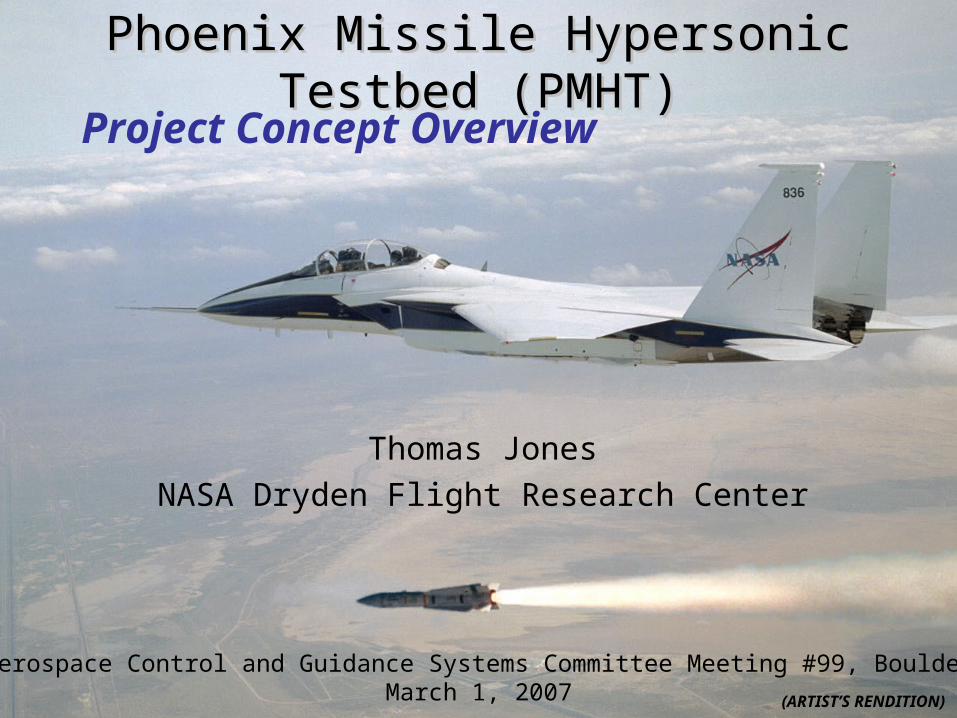
AIM-54 Internal Hardware Schematic
• All internal components removed from guidance and armament sections to make space for payload and new guidance computer and INU
• Components to be removed include warhead, old guidance computer, and radar tracker
GuidanceSection(184 lb)
Armament Section(184 lb)
Propulsion Section(511 lb)
ControlSection(144 lb)
13 feet
15 inches

Basic Payload Concept
Radome
Guidance Section
Armament Section
Propulsion Section
Control SectionWings
Control Surfaces
PrimaryPayloadSection
SecondaryPayloadSection
Rear Payload Volume TBD
New GuidanceSection
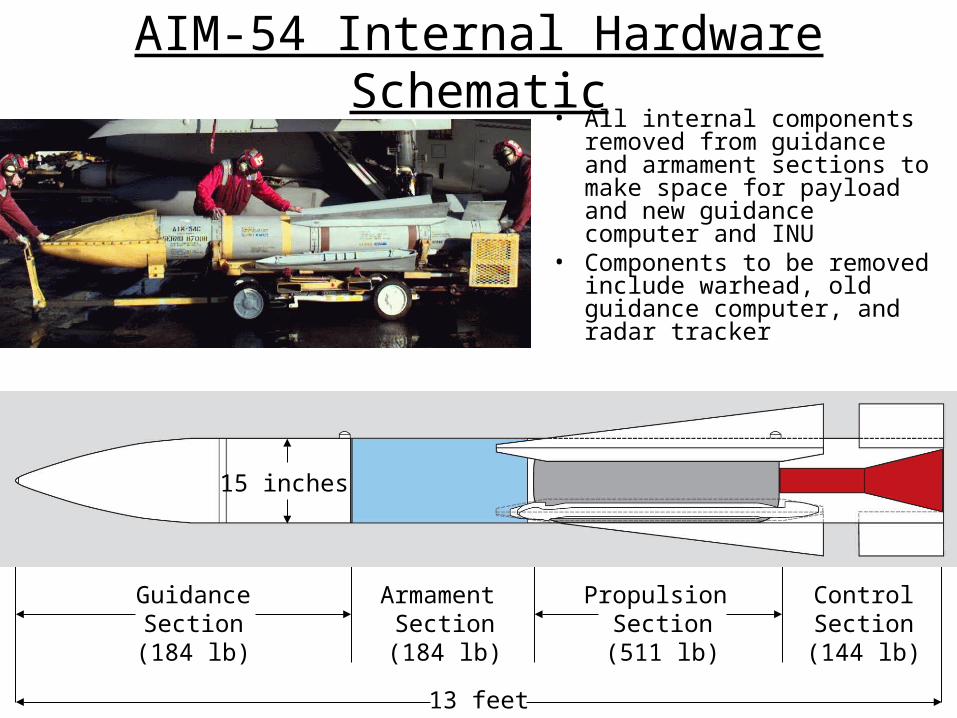
New Guidance and Armament Section Profiles
• Payload volume consists of two areas (primary and secondary) separated by a bulkhead at the location of a launch lug
• All internals of guidance and armament sections removed
• Secondary payload immediately aft of primary • Length of secondary payload is TBD, but in
the neighborhood of 12-18 inches
Primary Payload
SecondaryPayload
New GuidanceSection
~57 ~12 ~20
Former Guidance Section Former Armament Section
All dimensions in inches, unless noted otherwise
Guidance &Armament Sections
15
Missile LaunchLug
Bulkhead
• Payload instrumentation and power interfaces are TBD

Missile Preflight Activities• Mount the payload-integrated missile on the aircraft• Power aircraft using external ground power• Power Phoenix on external power via cockpit switched
power relay• Connect Ground Servicing Equipment (eg. Laptop) to
Phoenix GSE port– Upload guidance waypoints for planned trajectory– Upload controller and/or payload constants– Collect Phoenix telemetry via hardwire to GSE
• Verify system health and safety monitoring from aircraft rear cockpit display– Payload and missile systems instrumentation data available
through on-missile data bus• Verify INS performance• Command MOAT (Mission on Aircraft Test) from rear
cockpit• Ready A/C for takeoff

Notional Ground Path
Tanker
LAUNCHPOINT
Missile data is telemetered through Western Missile Pacific Test Range to Control Room for Immediate Data Review

0
0.5
1
1.5
2
2.5
3
x 105
Downrange Distance
Alt
itu
de,
ft High AltitudeHigh Altitude
0 ~300
1
2
3
4
5
Time, sec
Mac
h
High SpeedHigh Speed
0 ~3000
2000
4000
6000
8000
10000
Time, sec
Dyn
amic
Pre
ssu
re, p
sf
High QHigh Q
Sample Theoretical Trajectories
• The missile is capable of reaching useful high-speed test conditions
– 8 seconds > mach 5.0– 50 seconds > mach 4.5– Weight reductions improve performance
• High altitude test conditions in excess of 300kft are also kinetically possible
– Controllability of the store will limit this to <150kft without additional control mechanisms
• High dynamic pressure test conditions are also kinetically possible
– Structural and actuator authority limitations will reduce capability from kinetic theory

F-15B / Phoenix Missile Fit-check
November 14, 2006

Phoenix Adapter PylonF-15 Centerline Pylon Phoenix Interface Plate
Phoenix Adapter Pylon
Modified Inert Phoenix Missile

Possible Research Program Participants
• University Collaboration– Interested in utilizing the ARMD NASA Research
Announcement (NRA)• Industry Collaboration • NASA Specific
– ARMD– ESMD– SMD
• Other Government Agencies– DoD– DARPA– etc.

Possible Payloads• Propulsion
– Super/hypersonic inlet flight validation– Scramjet engine component validation including combustors and isolators– Fundamental combustion and flameholding
• Aerodynamics– Boundary layer laminar to turbulent transition experiment– External burning for transonic drag reduction– Supersonic parachute testing
• Systems– High speed flush air data system (FADS) validation– Avionics system flight validation
• Materials & Structures– High temperature seals– High temp leading edge validation– High temp instrumentation– TPS validation
• Guidance, Navigation, and Controls– Hypersonic control law validation– High speed GPS testing
• Science– High altitude research
• Others?

Estimated Development Milestone Schedule
• Evaluation of system performance envelope (prelim. estimates complete)• Aircraft/missile separation analysis (prelim. estimates complete)• Aircraft/adapter pylon hardware interface design and fit check (complete 10/14/06)• Aircraft performance analysis with captive missile (prelim. estimates complete)• Development of 6-DOF Simulation (in progress)• System requirements definition (in progress)• Aircraft/missile GVT (Mar 07)• System Requirements Review (SRR) (Mar 07)• Aircraft/adapter pylon electrical interface definition (Apr 07)• Miniaturized guidance & flight control computer prelim. design (Apr 07)• FTS and TM system prelim. design (Apr 07)• Prelim. navigation & control law development (Apr 07)• Preliminary Design Review (PDR) (May 07)• Initial envelope expansion & performance flights with captive inert missile (Jun 07)• Critical Design Review (CDR) (Nov 07)• HIL/VIL V&V ground testing (FY08 Q2)• Aircraft/missile separation flight test (FY08 Q3)• Live fire flight test (FY08 Q4)• Research payload flight tests (as nec. In FY09 and out)

Phoenix Fills Gaps in Flight Test Envelopes
• Bridges the large developmental gap between ground testing/analysis and major flight demonstrator X-planes and
PhoenixPlatform
• Provides subscale flight research data beyond the envelopes of existing piloted/ unpiloted flight test platforms to increase the amount of relevant flight data
• Air-launch allows launch altitude, attitude, and location to be flexible
• Guided testbed allows placement of payload at desired conditions
• Research payload can be checked-out in a captive-carry flight environment at altitudes
• Leverages NASA Dryden’s existing aircraft assets and NAWC Weapons Division’s operational experience
• Bridges the gap between envelopes of existing piloted/ unpiloted flight test platforms

Questions?
Top Related