


Languages
Pages
Legal


F. Meyer1), M. Eineder2), R. Brcic2), K. Papathanassiou3), J.-S. Kim3) , P. Rosen4)
1)Geophysical Institute, University of Alaska Fairbanks2)Remote Sensing Technology Institute, German Aerospace Center (DLR)
3)Microwaves and Radar Institute, German Aerospace Center (DLR)4)Jet Propulsion Laboratory, Pasadena
Performance Requirements for Correction of Ionospheric
Signals in L-band SAR Data
Collaborating Organizations:
F. MeyerAugust 2010, Zurich, CH 2
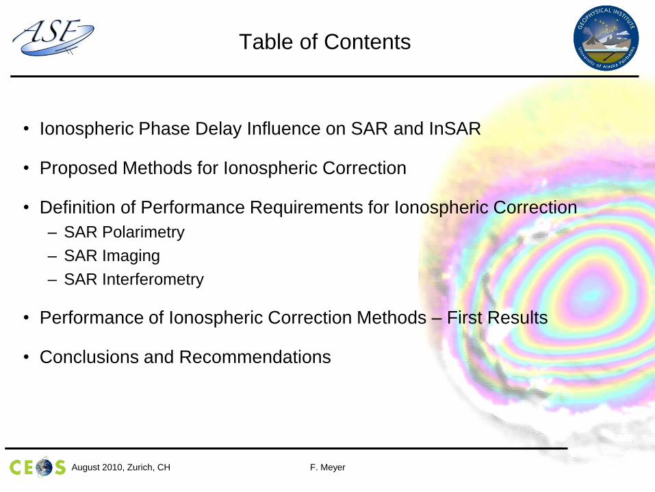
Table of Contents
• Ionospheric Phase Delay Influence on SAR and InSAR
• Proposed Methods for Ionospheric Correction
• Definition of Performance Requirements for Ionospheric Correction
– SAR Polarimetry
– SAR Imaging
– SAR Interferometry
• Performance of Ionospheric Correction Methods – First Results
• Conclusions and Recommendations
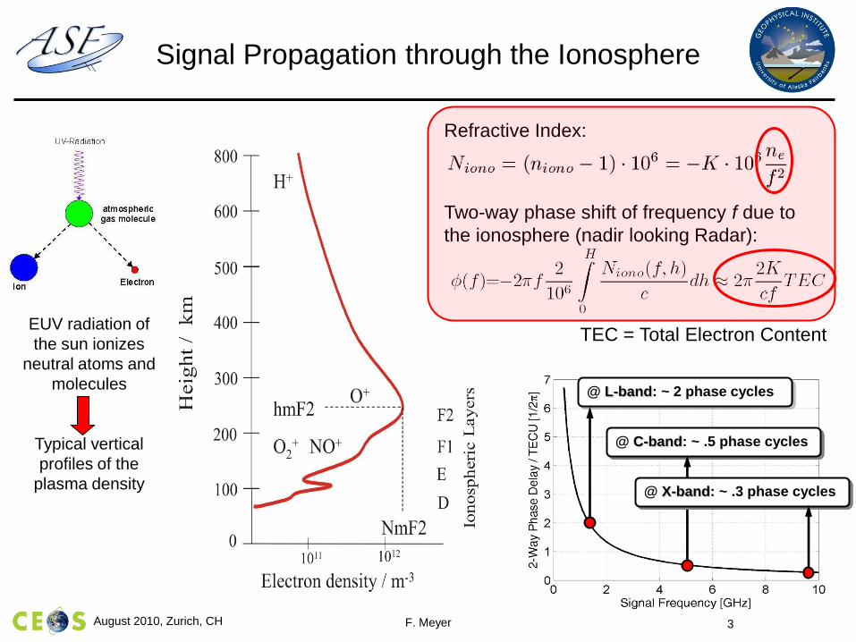
Signal Propagation through the Ionosphere
EUV radiation of
the sun ionizes
neutral atoms and
molecules
Typical vertical
profiles of the
plasma density
Refractive Index:
Two-way phase shift of frequency f due to
the ionosphere (nadir looking Radar):
TEC = Total Electron Content
@ L-band: ~ 2 phase cycles
@ C-band: ~ .5 phase cycles
@ X-band: ~ .3 phase cycles
F. Meyer 3August 2010, Zurich, CH
F. MeyerAugust 2010, Zurich, CH 4
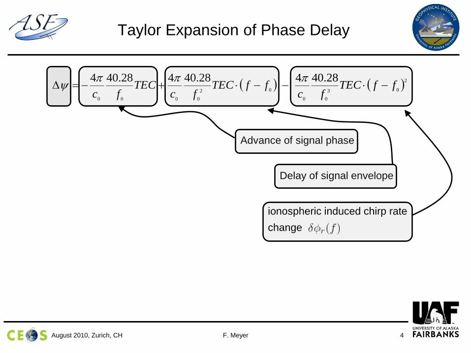
Taylor Expansion of Phase Delay
2
03
00
02
0000
28.40428.40428.404ffTEC
fcffTEC
fcTEC
fc
Advance of signal phase
Delay of signal envelope
ionospheric induced chirp rate
change
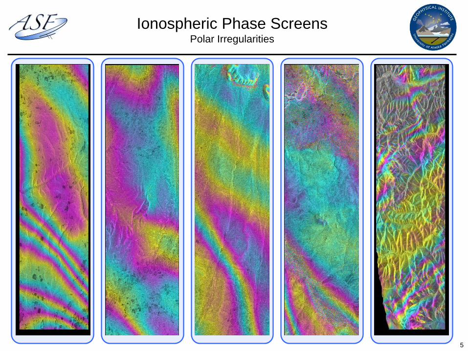
Ionospheric Phase ScreensPolar Irregularities
5
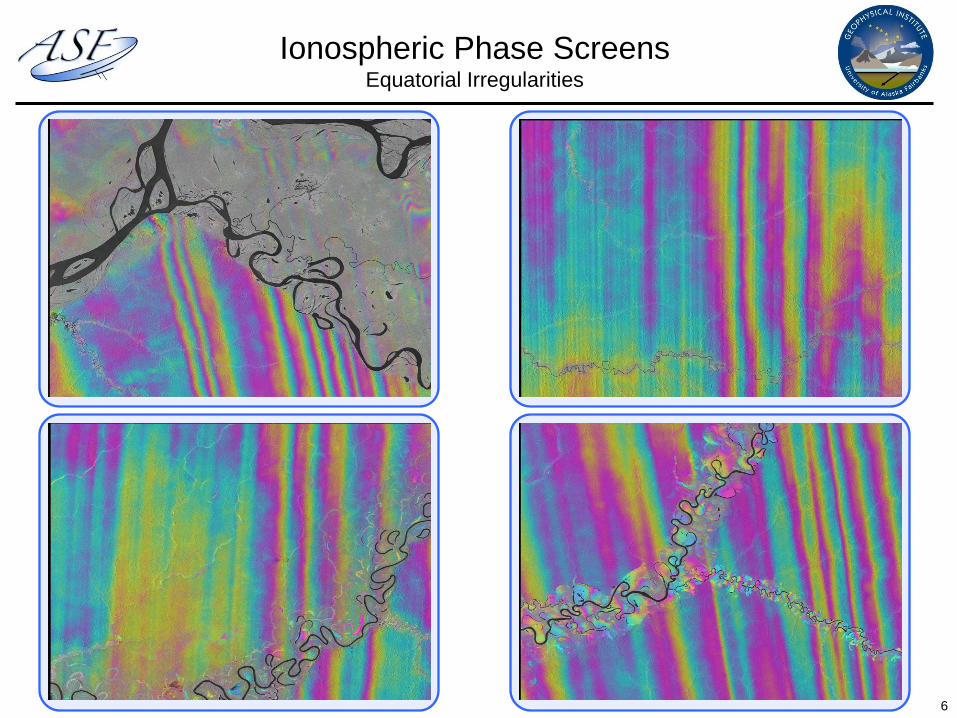
Ionospheric Phase ScreensEquatorial Irregularities
6

F. MeyerAugust 2010, Zurich, CH 7
Faraday Rotation
• Faraday Rotation changes polarimetric angle with which a system observes the earth surface
• Currently -10º - 10º in L-band but increase to ~25º expected at solar max.
• In P-band, W may be subject to wrapping
Transmitted signal Signal at ground level
WTECB
f
KW seccos
2
Magnetic field intensity &
angle with observation direction
F. MeyerAugust 2010, Zurich, CH 9
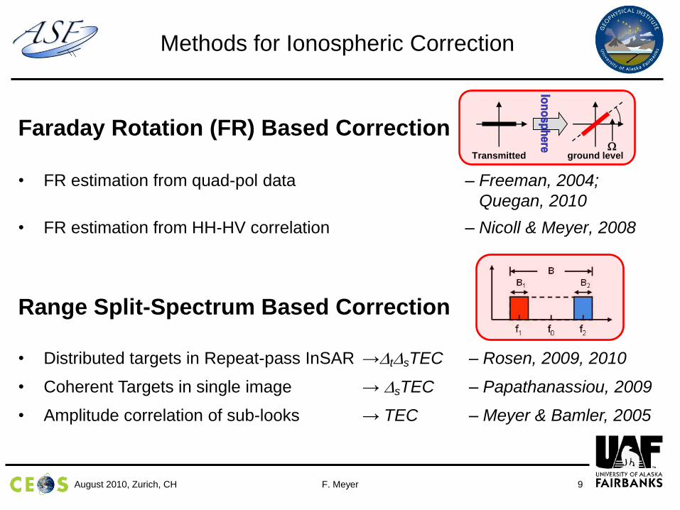
Methods for Ionospheric Correction
Faraday Rotation (FR) Based Correction
• FR estimation from quad-pol data – Freeman, 2004;
Quegan, 2010
• FR estimation from HH-HV correlation – Nicoll & Meyer, 2008
Range Split-Spectrum Based Correction
• Distributed targets in Repeat-pass InSAR →tsTEC – Rosen, 2009, 2010
• Coherent Targets in single image → sTEC – Papathanassiou, 2009
• Amplitude correlation of sub-looks → TEC – Meyer & Bamler, 2005
Transmitted ground levelW

F. MeyerAugust 2010, Zurich, CH 10
Methods for Ionospheric Correction
Azimuth Autofocus Based Correction
• Contrast maximization for point targets – several authors
• Coherent AF: Phase Curvature analysis – Papathanassiou, 2008
• Incoherent AF: Sub-look co-registration (MLR) – Meyer & Nicoll, 2008
Hybrid Methods
• Combination of range and phase offsets in InSAR – Meyer, 2005
• Two dimensional phase signature of point targets – Papathanassiou
• …

F. MeyerAugust 2010, Zurich, CH 11
Problem Statement
• Question to Answer:
How accurate does correction have to be?
• This paper defines requirements for ionospheric correction based on
calibration specifications
• Requirements will be derived for SAR Polarimetry, SAR Imaging, and SAR
Interferometry
• Notes:
• Given a set of calibration specs, the maximum allowable error in ionospheric
correction is calculated
• is calculated such that 95% of all corrected image pixels will fulfill
calibration specs (2 sigma law)
max,W
max,W
F. MeyerAugust 2010, Zurich, CH 12
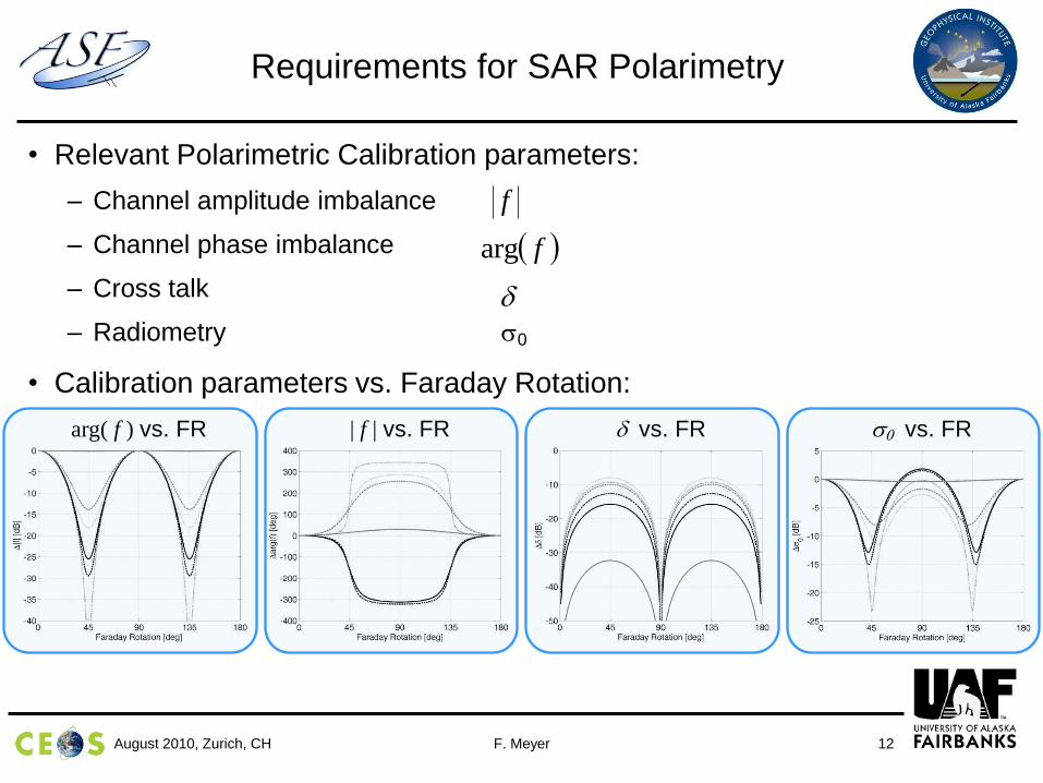
Requirements for SAR Polarimetry
• Relevant Polarimetric Calibration parameters:
– Channel amplitude imbalance
– Channel phase imbalance
– Cross talk
– Radiometry 0
• Calibration parameters vs. Faraday Rotation:
f
farg
arg( f ) vs. FR | f | vs. FR vs. FR 0 vs. FR
F. MeyerAugust 2010, Zurich, CH 13
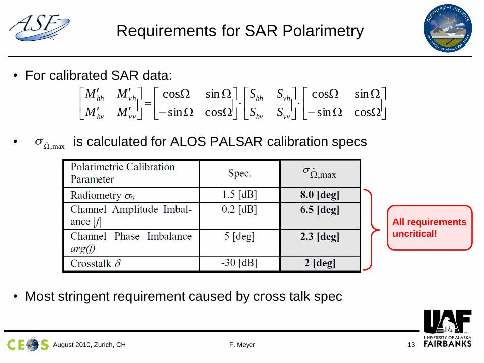
Requirements for SAR Polarimetry
• For calibrated SAR data:
• is calculated for ALOS PALSAR calibration specs
• Most stringent requirement caused by cross talk spec
WW
WW
WW
WW
cossin
sincos
cossin
sincos
vvhv
vhhh
vvhv
vhhh
SS
SS
MM
MM
max,W
All requirements
uncritical!
F. MeyerAugust 2010, Zurich, CH 14
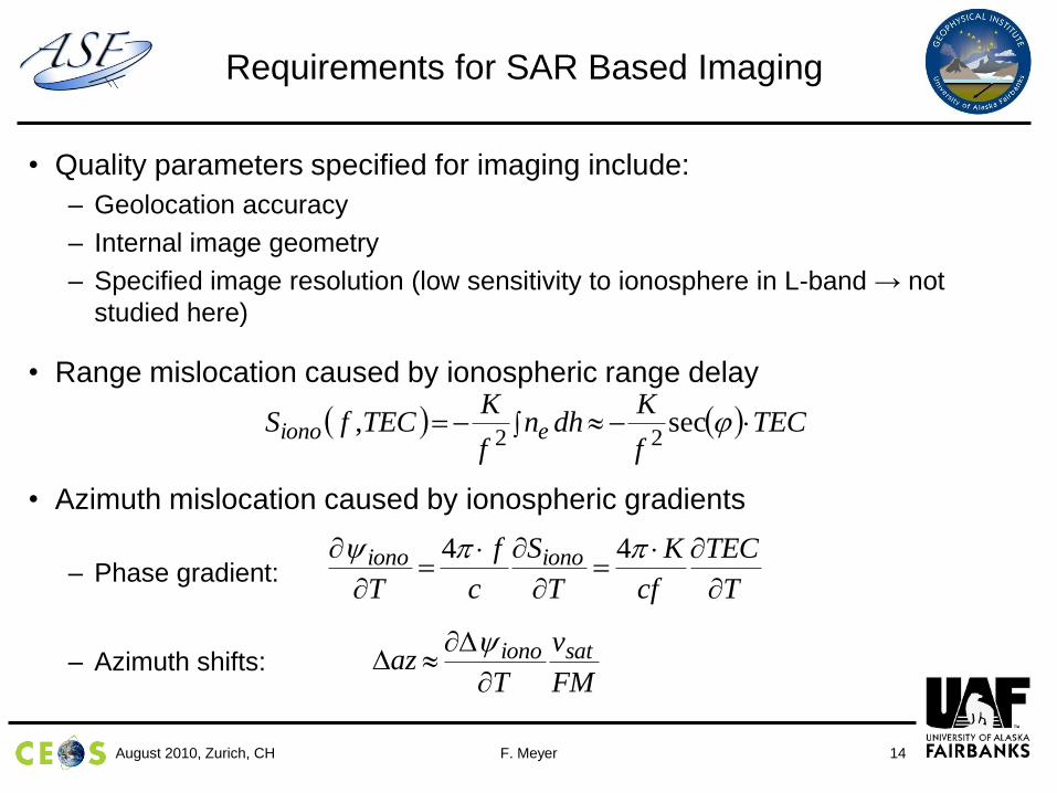
Requirements for SAR Based Imaging
• Quality parameters specified for imaging include:
– Geolocation accuracy
– Internal image geometry
– Specified image resolution (low sensitivity to ionosphere in L-band → not
studied here)
• Range mislocation caused by ionospheric range delay
• Azimuth mislocation caused by ionospheric gradients
– Phase gradient:
– Azimuth shifts:
T
TEC
cf
K
T
S
c
f
T
ionoiono
44
TECf
Kdhn
f
KTECfS eiono sec,
22
FM
v
Taz sationo
F. MeyerAugust 2010, Zurich, CH 15
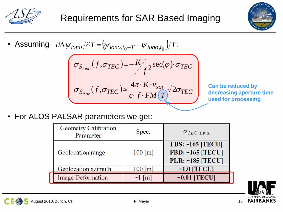
Requirements for SAR Based Imaging
• Assuming :
• For ALOS PALSAR parameters we get:
TT tionoTtionoiono 00 ,,
TECTECSf
Kfiono
sec, 2
TECsat
TECSTFMfc
vKf
az
2
4,
Can be reduced by
decreasing aperture time
used for processing

F. MeyerAugust 2010, Zurich, CH 16
Requirements for SAR Interferometry
• Ionosphere induced interferometric phase component at pixel k
corresponds to:
• Main applications of InSAR:
– Topographic mapping
– Deformation monitoring
ktkionoktionok TECf
K
c
sec
4,,
kkk
ktopo H
R
B
sin
4 ,
kdefo r
4
TECk
k
kH
Bf
KRk
2tan
,2
TEC
k
rf
Kk
2cos2
F. MeyerAugust 2010, Zurich, CH 17
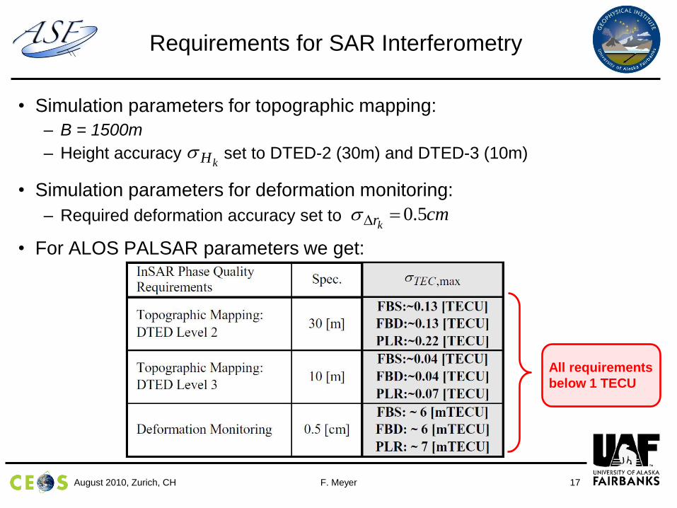
Requirements for SAR Interferometry
• Simulation parameters for topographic mapping:
– B = 1500m
– Height accuracy set to DTED-2 (30m) and DTED-3 (10m)
• Simulation parameters for deformation monitoring:
– Required deformation accuracy set to
• For ALOS PALSAR parameters we get:
kH
cmkr
5.0
All requirements
below 1 TECU
F. MeyerAugust 2010, Zurich, CH 18
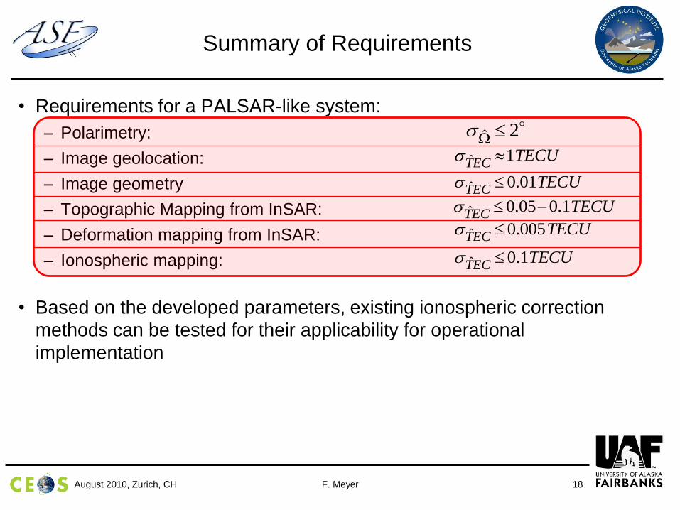
• Requirements for a PALSAR-like system:
– Polarimetry:
– Image geolocation:
– Image geometry
– Topographic Mapping from InSAR:
– Deformation mapping from InSAR:
– Ionospheric mapping:
• Based on the developed parameters, existing ionospheric correction
methods can be tested for their applicability for operational
implementation
Summary of Requirements
TECUECT
1ˆ
2ˆ W
TECUECT
01.0ˆ
TECUECT
1.005.0ˆ
TECUECT
005.0ˆ
TECUECT
1.0ˆ
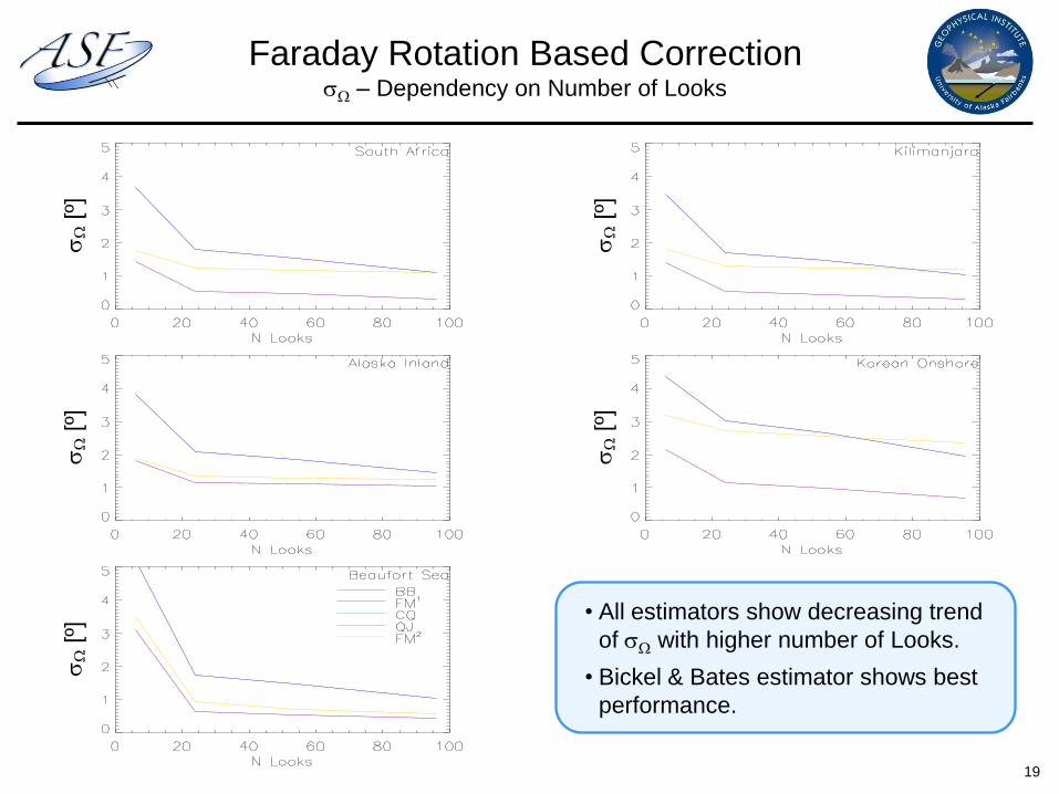
Faraday Rotation Based CorrectionW – Dependency on Number of Looks
• All estimators show decreasing trend
of W with higher number of Looks.
• Bickel & Bates estimator shows best
performance.
19
W
[º]
W
[º]
W
[º]
W
[º]
W
[º]
F. MeyerAugust 2010, Zurich, CH 20
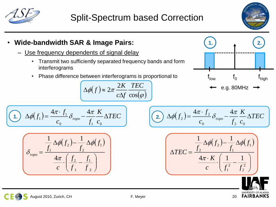
• Wide-bandwidth SAR & Image Pairs:
– Use frequency dependents of signal delay
• Transmit two sufficiently separated frequency bands and form
interferograms
• Phase difference between interferograms is proportional to
Split-Spectrum based Correction
cos
22
TEC
fc
Kf
f0flow fhigh
e.g. 80MHz
TECc
K
fc
ff topo
010
1
1
44
TEC
c
K
fc
ff topo
020
2
2
44
2
1
1
2
1
2
2
1
4
11
f
f
f
f
c
ff
ff
topo
2
2
2
1
1
1
2
2
114
11
ffc
K
ff
ff
TEC
2.1.
1. 2.
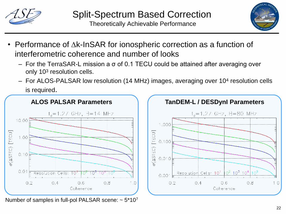
Split-Spectrum Based CorrectionTheoretically Achievable Performance
• Performance of k-InSAR for ionospheric correction as a function of
interferometric coherence and number of looks
– For the TerraSAR-L mission a σ of 0.1 TECU could be attained after averaging over
only 103 resolution cells.
– For ALOS-PALSAR low resolution (14 MHz) images, averaging over 104 resolution cells
is required.
22
ALOS PALSAR Parameters TanDEM-L / DESDynI Parameters
Number of samples in full-pol PALSAR scene: ~ 5*107
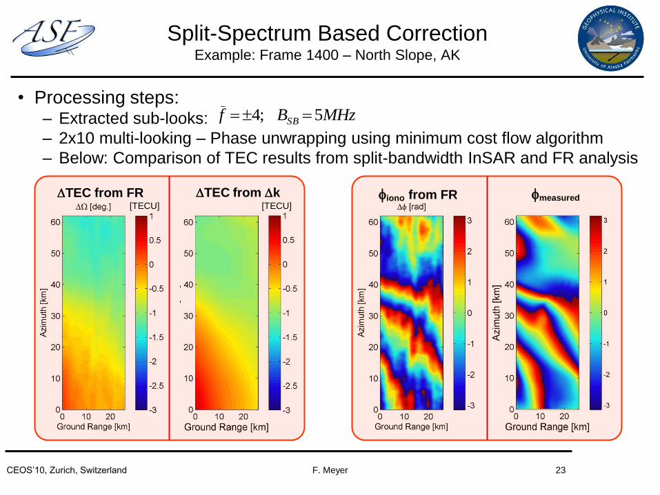
• Processing steps:– Extracted sub-looks:
– 2x10 multi-looking – Phase unwrapping using minimum cost flow algorithm
– Below: Comparison of TEC results from split-bandwidth InSAR and FR analysis
Split-Spectrum Based CorrectionExample: Frame 1400 – North Slope, AK
MHzBf SB 5;4
[TECU] [TECU]
TEC from FR TEC from k iono from FR measured
F. MeyerCEOS’10, Zurich, Switzerland 23
F. MeyerAugust 2010, Zurich, CH 24
• Requirements for ionospheric correction were derived
• Requirements were defined such that corrected data meets calibration
specs and advertised system capabilities
• InSAR applications require strictest correction quality
• First analyzes and example show operational feasibility of correction
techniques
• Theoretically achievable performance parameters were derived
• Improved (integrated) correction methodology under development
Conclusions
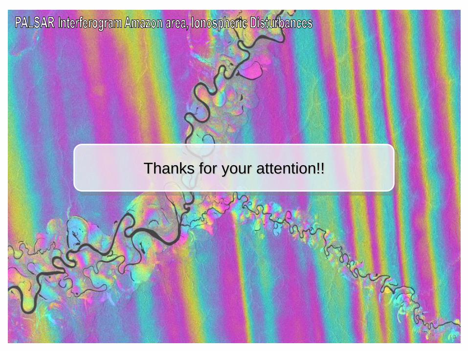
Thanks for your attention!!
Top Related