


Languages
Pages
Legal


Percutaneous MV Repair
Steven A. Goldstein MD FACC, FASEDirector, Noninvasive CardiologyMedstar Heart InstituteWashington Hospital CenterTuesday, October 11, 2016

DISCLOSURE
I have N O relevant financial relationships

3D-TEE in Mitral Interventions
• Surgical mitral valve repair (Operating Rm)
• Edge-to-edge repair of mitral regurgitation
• Transcatheter MV insertion (TMVI)(e.g.,Tendyne)
• Closure of paravalvular mitral regurgitation
• Valve-in-valve implantation
• Balloon mitral valvuloplasty (mitral stenosis)

Echo for MV Disease• Mitral valve anatomy/pathology
• Quantitation of MR
• Procedural guidance
Mechanism(s) of MV disease

Unlike AS singular pathology
MR highly variable etiologies

MV anatomy/pathology

Dilatation
Mitral Valve ApparatusLeft atrium
Annulus
Leaflets
Chordae tendinae
Papillarymuscles
LV freewall
DilatationCalcificationProlapseRedundancyThickeningPerforationCleftCommissural fusionAbnormal insertionElongationRuptureThickening/fusionIschemiaFibrosisRupture
Lateral displacement(ischemia, fibrosis, dilatation)

Septo-Lateral distance
Tenting Height
Coaptationlength
Inter-commissural distance
Coapt Displ
Aorta
Tent Vol

LeafletOverlap

Tenting areaLeafletoverlap
Coaptation depth

Normal
Restricted PML
Dilated anulus
Ruptured pap muscle
Prolapse
Mechanisms of Mitral Regurgitation
ApicalTethering

Ruptured cords

Case 1Ruptured cords P2

Ruptured cord P2
Case 2

MVP

Normal
Restricted PML
Dilated anulus
Ruptured pap muscle
Prolapse
Mechanisms of Mitral Regurgitation
ApicalTethering

Mitral Valve Prolapse
Case 4

Functional MR

Normal
Restricted PML
Dilated anulus
Ruptured pap muscle
Prolapse
Functional Mitral Regurgitation
ApicalTethering

Morphologic Changes in Heart Failure
Bolling J Heart Valve Dis 11:S28(2002)
Papillary muscles displaced apically and laterally

Functional Mitral Regurgitation -Mechanisms
• Global LV dysfunction• Regional LV dysfunction• Increased sphericity of LV• Excessive pap muscle displacement• Decreased overlap of leaflets• LA enlargement• Loss of systolic mitral annular contraction• Increased “tenting” area• Delayed activation of P-M pap muscle (dyssynchrony)
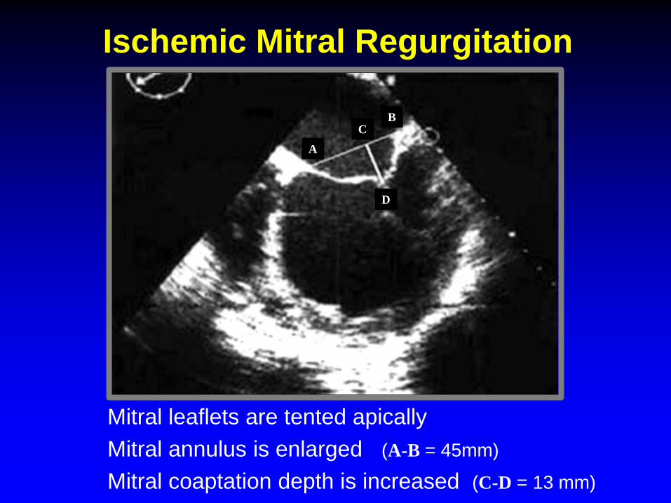
AC
B
D
Ischemic Mitral Regurgitation
Mitral leaflets are tented apicallyMitral annulus is enlarged (A-B = 45mm)
Mitral coaptation depth is increased (C-D = 13 mm)

Procedural Guidance

Wánghòu
Queen ofStructural Heart Disease

Essentials for Echo-Guidance
• Pre-procedure strategy b/w echocardiographer
• Common understanding of appropriate and
• Presentation of echo images on main monitor
and interventionalist
necessary echo views
NOTE: Fluoro limited b/c MV has no calcium
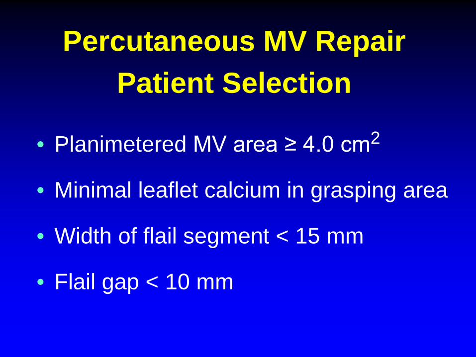
Percutaneous MV RepairPatient Selection
• Planimetered MV area ≥ 4.0 cm2
• Minimal leaflet calcium in grasping area
• Width of flail segment < 15 mm
• Flail gap < 10 mm

adapted from Cavalcante JACC CV Imaging 2012;5:733-746
Functional MR Degenerative MR
Flail Gap<10 mm
Flail Width< 15 mm
CoaptationLength ≥2 mm
CoaptationDepth <11 mm
Eligibility Criteria for MitraClip

MitraClip ProcedureIdeal MV Morphology
• MR originating from mid-portion of MV
• Lack of calcification in the grasping area• MV area > 4 cm2• Length of posterior leaflet ≥10 mm• Non-rheumatic or non-endocarditic MVD• Flail width < 15 mm; flail gap < 10 mm• Sufficient leaflet tissue for coaptation
(degenerative or functional etiology)
(coaptation depth < 11 mm; coaptation length >2 mm)

The Mitral Valve and Subvalve Apparatus
Note lack of chordae in mid-portion of anterior leaflet

MitraClip ProcedureLess-than-Ideal MV Morphology
• Perforated MV leaflets; cleft MV leaflets
• Severe calcification in the grasping area
• Hemodynamically relevant mitral stenosis
• Length of posterior leaflet < 7 mm
• Rheumatic valve disease
• Gap between leaflets > 10 mm

Suitability for MitraClip Therapy
• Location/extent of flail/prolapsing segment
• Determine flail gap (<10 mm)
• Width of the flail segment (<15 mm)
• Coaptation depth (≤ 11 mm)
• Coaptation length (≥ 2 mm)
(distance from tip of flail segment to opposing leaflet)
DM
RFM
R
Classical EVEREST Criteria

Suitability for MitraClip Therapy
• Signif. Leaflet calcification in grasping area
• Very short posterior leaflet
• Rigidity of leaflets
• Extensive thickening of leaflets (Barlow’s)
• Significant cleft
• Perforation of leaflet
Unsuitable Valve Morphology

Suitability for MitraClip Therapy
• Pathology in segments 1 or 3 of either leaflet
• Mild calcification outside the grasping area
• MV area between 3 cm2 and 4 cm2
• Flail width > 15 mm – amenable to multiple clips
• Coaptation depth ≥ 11 mm
• Mobile post. leaflet length b/w 6-7 and 10 mm
“Conditionally” Suitable Valve Morphology

MitraClip ProcedureEcho Guidance

Guidance of the Procedure1. Transseptal puncture
2. Steerable guide catheter (SGC) insertion into LA
3. Advancement of Clip Delivery System through the
4. Steering/positioning MitraClip in the LA above MV
5. Advancing MitraClip into the LV
6. Grasping the leaflets/verifying proper insertion
7. Assessment of result before clip detachment
8. Clip detachment
SGC into the LA

1. Transseptal Puncture
• Optimal puncture site important for MitraClip
• Facilitates steering maneuvers
• Minimizes complexity and duration of procedure
• Preferred site superior-posterior portion offossa ovalis
continued . . .

1. Transseptal Puncture
• Short-axis view at base (~30-50º)
• Long-axis view (bicaval) - (~90-120º)
• Four-chamber view (~0º)
(anterior-posterior orientation)
(superior-inferior orientation)
(correct height above mitral valve)
3D X-plane can present SAX and long-axis simultaneously

1. Transseptal PunctureEcho Guidance
• Too low too close to MV
• High preferred want the approach to beperpendicular to the MV
superior and posterior

IVC
Aorta
LAA
Posterior (over coaptation line)
Anterior (not ideal)
Fossa
A1
A2
A3P1
P2
P3
Direction of Transseptal
Standard from IVC through center of fossa ovalis too anteriorPreferred for MitraClip posterior (over the coaptation line)

1. Transseptal Puncture
Tip of transseptal needle creates “tenting” of the atrial septum toward LA
5.0 cm

4.4 cm

1. Transseptal Puncture
• Primary MV disease 4-5 cm above annulus
• Secondary MR ~ 3.5 cm
Provides space to maneuver the MitraClipdelivery system within the LA
Optimal site above MV differs for primary (degenerative) vs secondary (functional) MR
Tenting results in a shift in position of closure line to below the mital annulus

2. Steerable Guide Catheter (SGC) Insertion into the LA
• Exchange guidewire placed in LUPV
• SGC gently advanced over the guidewire
• Done with fluoro and TEE guidance
• SGC catheter has echo-bright double ring
• SGC securely placed ~ 2-3cm within LA
that can be seen by TEE needs to be in LA
(to avoid injury to free LA wall)
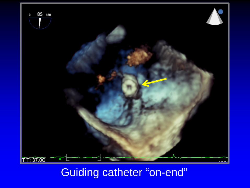
Guiding catheter “on-end”

3. Advancement of Clip Delivery System (CDS) through the SGC into LA
• CDS advanced thru the Steerable Guide
• Tip of clip reaches tip of SGC (fluoro)
• CDS then further advanced into LA
• Clip should be free from LA wall and MV
Catheter (SGC)

• Align clip perpendicular to mitral valve
• Move in small iterations • Center over origin of MR jet
• X-Plane images:
• If only 2D-TEE available transgastric SAX
coaptation line (≈1 cm above valve)
(direct tip of clip towards largest PISA)
4. Steering/Positioning MitraClipin the LA above the MV
- Intercommissural view- LVOT view

4. Steering Clip Perpendicular to Coaptation Line - Echo Guidance
• Align clip arms perpendicular to the
• Maintain clip open to at 180º to help
• Advance clip into LV just below the
line of coaptation
visualize the clip arms
leaflet edges prior to grasping

Steering and Positioning the MitraClip above the MV
Wunderlich and Siegel Eur Heart J: CV Imaging 2013;;14:935-949
• Align clip perpendicular to plane of mitral annulus• Align clip arms perpendicular to coaptation line• Align clip parallel to antegrade flow• Move in small iterations • Center over origin of MR jet

5. Advancing MitraClip into the LV• System advanced across MV into LV
• Usually clip is fully opened• Reassess orientation of the clip
• X-plane imaging is best:• Correct positioning:
(≈ 2 cm below the MV)
- Intercommissural view- LVOT view
- Perpendicular to line of MV coaptation- Both leaflets move freely above the clip- Clip splits the MR jet
(Clip may rotate during “dive” into LV)

6. Grasping of LeafletsVerification of Adequate Leaflet Insertion
• Grip arms placed in grasping position (≈120º)
• Pull back during systole to capture leaflets• Verify both leaflets inserted into the clip• Limited leaflet mobility relative to tips of clip arms• Adequate degree of MR reduction
• Creation of a double MV orifice• Degree of MS
(if not adequate move clip or place 2nd clip)
Midesophageallong-axis view

Leaflets need to move freely above the arms

Beigel J Am Coll Cardiol 2014;64(4):2688-2700
MitraClip System - Dimensions

6. Grasping of the Leaflets
PML AML

6. Assessment of Leaflet CaptureEcho Guidance
• Clip partially closed to secure insertion
• Carefully assess the grasp
of leaflets into the clip
leaflets: - Adequacy of leaflet insertion- Resultant degree of MR
Then, close the clip incrementally under echo-guidance

7. Assess Results before Clip Release
• Adequate leaflet insertion
• Degree of MR
• Degree of MS:
• Achievement of double orifice
(Currently no consensus
- MV area > 1.5 cm2
- Mean gradient ≤ 5 mm Hg
guidelines or validated studies on how to best evaluate residual MR)

8. Clip Release
• Reconfirm stable clip position
• Reassess grade of residual MR
• Achievement of double orifice
• Check for pericardial effusion
• Degree of shunting through the transseptalpuncture site (iatrogenic ASD)
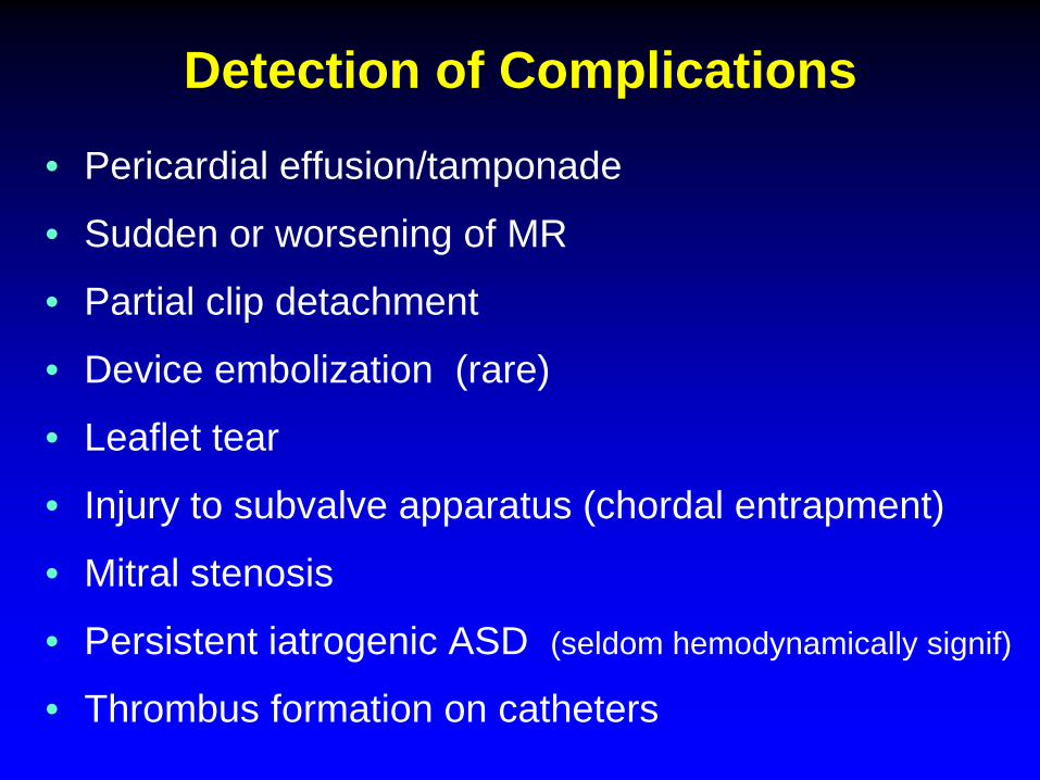
Detection of Complications• Pericardial effusion/tamponade
• Sudden or worsening of MR
• Partial clip detachment
• Device embolization (rare)
• Leaflet tear
• Injury to subvalve apparatus (chordal entrapment)
• Mitral stenosis
• Persistent iatrogenic ASD (seldom hemodynamically signif)
• Thrombus formation on catheters
Case 26TTE 1 day post MitraClip insertion


TranscatheterMV Insertion (TMVI)

Blanke J Am Coll Cardiol Img. 2015;8(10):1191-1208.
Tiara FORTIS Tendyne
CardiAQ
Transcatheter Mitral Valves Currently in Human Trials

Blanke J Am Coll Cardiol Img. 2015;8(10):1191-1208.
Various TMVI Anchoring Mechanisms
Tabs Paddles Barbs Tether(Neocord)

Percutaneous MV Replacement (TMVR)
• In a phase of product development
• Limited clinical experience
• Greater obstacles/challenges than TAVI

Challenges to Percutaneous TMVR Devices• Asymmetrical saddle-shaped annulus• Large annulus size large devices• Dynamic changes in annulus size during cardiac cycle• No stable calcified structure for anchoring (most cases)• Irregular geometry of mitral leaflets• Obstruction of LV outflow tract• Preservation of subvalve apparatus mandatory to
preserve LV geometry• Thrombogenicity of a bulky device• Perforation of adjacent structures• Potential for:
• Even mild paravalve leak may result in hemolysis
- occlusion of left circumflex artery- compression of coronary sinus- conduction system disruption
Top Related