


Languages
Pages
Legal


Parts and Accessories.Installation Instructions.
Rear-View Camera RetrofitBMW 7 Series (E 65 and E 66)
These installation instructions are only valid for cars with SA 609 (navigation system).
Retrofit kit No.: 84 21 0 302 940
Installation timeThe installation time is approx 3.0 - 3.5 hours, but this may vary depending on the condition of the car and the equipment in it.
Important information These installation instructions are primarily designed for use within the BMW dealership organisation and by authorised BMW service companies;
In any event the target group for these installation instructions is specialist personnel trained on BMW cars with the appropriate specialist knowledge.
All work must be completed using the latest BMW repair manuals, circuit diagrams, servicing manuals and work instructions in a rational order using the prescribed tools (special tools) and observing current health and safety regulations.
Ensure that the cables/lines are not kinked or damaged as you install them in the car. The costs incurred as a result of this will not be reimbursed by BMW AG.
Additional cables/lines that you install must be secured with cable ties.
If the specified PIN chambers are occupied, bridges, double crimps or twin-lead terminals must be used.
Before you install the retrofit system, test the control module status with the CIP (coding, customising, programming) test program. If the test detects incorrect statuses in one or more control modules, these must be updated first using the �Load software� function.
All the figures show LHD cars, proceed accordingly on RHD cars.
Pictograms:
denotes instructions that draw your attention to dangers.
denotes instructions that draw your attention to special features.
! denotes the end of the instruction or caution text.
See the EBA CD or Aftersales Portal for explanations of the pictograms.
Do not archive the hard copy of these installation instructions since daily updates are made by Aftersales Portal.
Subject to technical modifications.
!
© BMW AG, München EBA-Nr.: 01 29 0 300 852 Stand: 06.2003 EN/1

List of special equipmentThe following special equipment must be taken into consideration when installing the retrofit kit:
SA 609 Navigation system
Special tools requiredNone
EN/2© BMW AG, München EBA-Nr.: 01 29 0 300 852 Stand: 06.2003
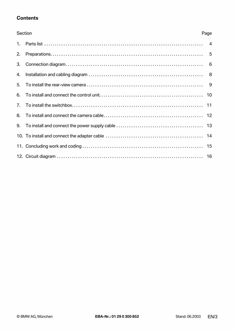
Contents
Section Page
1. Parts list . . . . . . . . . . . . . . . . . . . . . . . . . . . . . . . . . . . . . . . . . . . . . . . . . . . . . . . . . . . . . . . . . . . . . . . . . . . 4
2. Preparations. . . . . . . . . . . . . . . . . . . . . . . . . . . . . . . . . . . . . . . . . . . . . . . . . . . . . . . . . . . . . . . . . . . . . . . . 5
3. Connection diagram. . . . . . . . . . . . . . . . . . . . . . . . . . . . . . . . . . . . . . . . . . . . . . . . . . . . . . . . . . . . . . . . . 6
4. Installation and cabling diagram . . . . . . . . . . . . . . . . . . . . . . . . . . . . . . . . . . . . . . . . . . . . . . . . . . . . . . 8
5. To install the rear-view camera . . . . . . . . . . . . . . . . . . . . . . . . . . . . . . . . . . . . . . . . . . . . . . . . . . . . . . . 9
6. To install and connect the control unit. . . . . . . . . . . . . . . . . . . . . . . . . . . . . . . . . . . . . . . . . . . . . . . . . 10
7. To install the switchbox. . . . . . . . . . . . . . . . . . . . . . . . . . . . . . . . . . . . . . . . . . . . . . . . . . . . . . . . . . . . . . 11
8. To install and connect the camera cable. . . . . . . . . . . . . . . . . . . . . . . . . . . . . . . . . . . . . . . . . . . . . . . 12
9. To install and connect the power supply cable . . . . . . . . . . . . . . . . . . . . . . . . . . . . . . . . . . . . . . . . . 13
10. To install and connect the adapter cable . . . . . . . . . . . . . . . . . . . . . . . . . . . . . . . . . . . . . . . . . . . . . . 14
11. Concluding work and coding . . . . . . . . . . . . . . . . . . . . . . . . . . . . . . . . . . . . . . . . . . . . . . . . . . . . . . . . . 15
12. Circuit diagram . . . . . . . . . . . . . . . . . . . . . . . . . . . . . . . . . . . . . . . . . . . . . . . . . . . . . . . . . . . . . . . . . . . . . 16
EN/3© BMW AG, München EBA-Nr.: 01 29 0 300 852 Stand: 06.2003
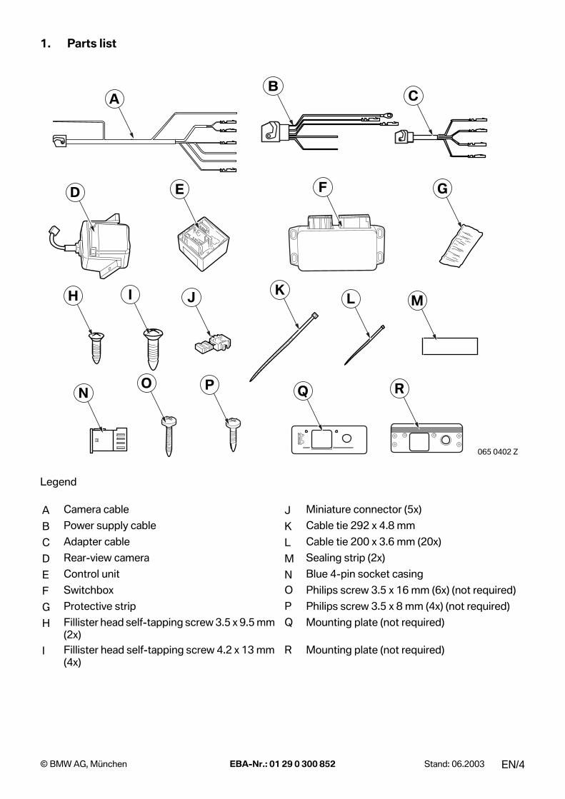
1. Parts list
Legend
A Camera cable J Miniature connector (5x)
B Power supply cable K Cable tie 292 x 4.8 mm
C Adapter cable L Cable tie 200 x 3.6 mm (20x)
D Rear-view camera M Sealing strip (2x)
E Control unit N Blue 4-pin socket casing
F Switchbox O Philips screw 3.5 x 16 mm (6x) (not required)
G Protective strip P Philips screw 3.5 x 8 mm (4x) (not required)
H Fillister head self-tapping screw 3.5 x 9.5 mm (2x)
Q Mounting plate (not required)
I Fillister head self-tapping screw 4.2 x 13 mm (4x)
R Mounting plate (not required)
065 0402 Z
BA C
D E F G
H I LJ KM
N RO P Q
EN/4© BMW AG, München EBA-Nr.: 01 29 0 300 852 Stand: 06.2003
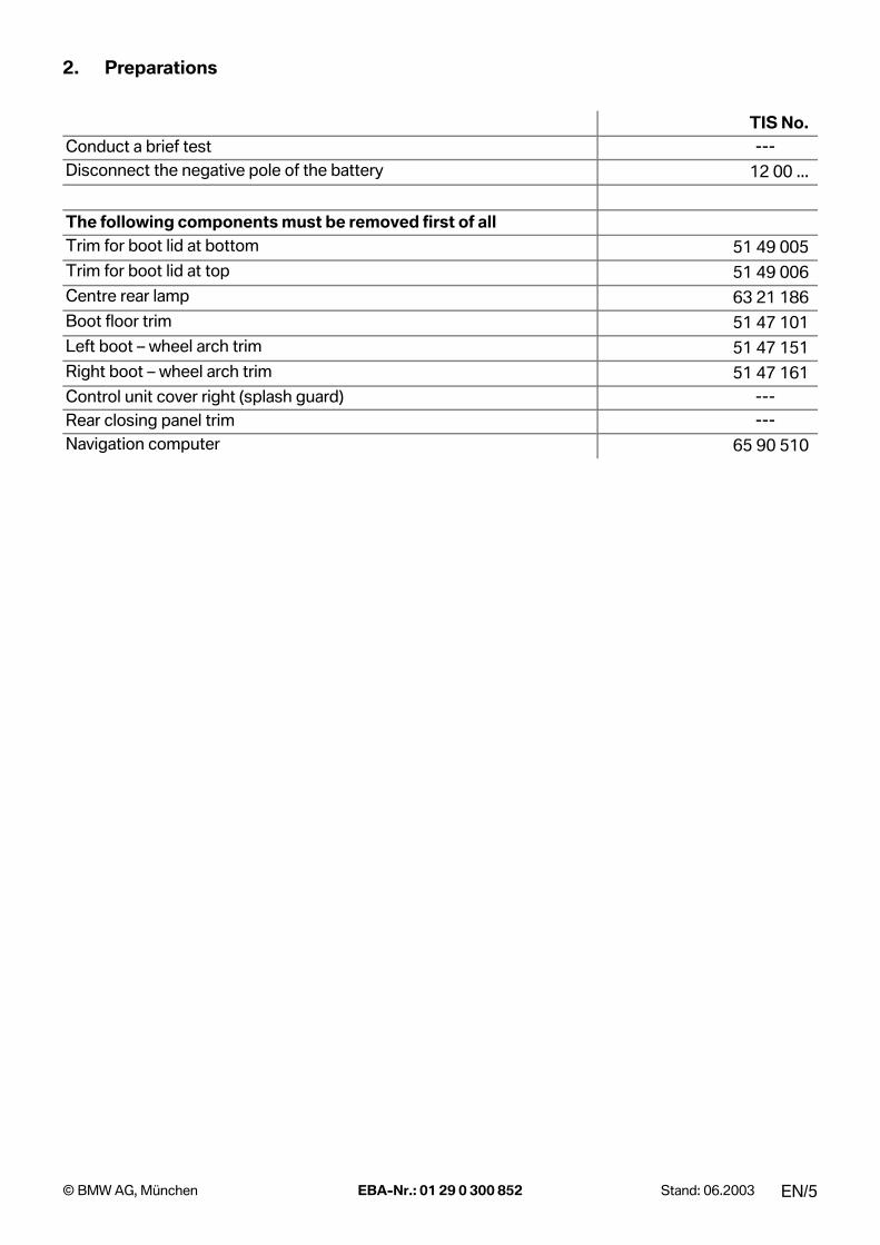
2. Preparations
TIS No.Conduct a brief test ---Disconnect the negative pole of the battery 12 00 ...
The following components must be removed first of allTrim for boot lid at bottom 51 49 005Trim for boot lid at top 51 49 006Centre rear lamp 63 21 186Boot floor trim 51 47 101Left boot � wheel arch trim 51 47 151Right boot � wheel arch trim 51 47 161Control unit cover right (splash guard) ---Rear closing panel trim ---Navigation computer 65 90 510
EN/5© BMW AG, München EBA-Nr.: 01 29 0 300 852 Stand: 06.2003
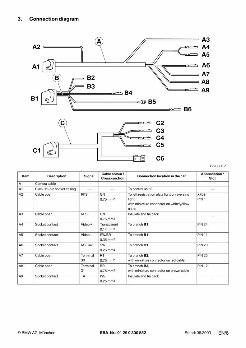
3. Connection diagram
Item Description SignalCable colour / Cross-section
Connection location in the carAbbreviation /
Slot
A Camera cable --- --- --- ---
A1 Black 12-pin socket casing --- --- To control unit E ---
A2 Cable open RFS GN0.75 mm2
To left registration plate light or reversing light,with miniature connector on white/yellow cable
X709PIN 1
A3 Cable open RFS GN0.75 mm2
Insulate and tie back---
A4 Socket contact Video + Transparent0.14 mm2
To branch B1 PIN 24
A5 Socket contact Video - SW/BR0.35 mm2
To branch B1 PIN 11
A6 Socket contact RSF inv SW0.25 mm2
To branch B1 PIN 23
A7 Cable open Terminal 30
RT0.75 mm2
To branch B2,with miniature connector on red cable
PIN 25
A8 Cable open Terminal 31
BR0.75 mm2
To branch B3,with miniature connector on brown cable
PIN 12
A9 Socket contact TA WS0.25 mm2
Insulate and tie back---
065 0386 Z
B1
B2
B3 B4
B5 B6
C1
C2 C3 C4 C5
C6
B
C
A1A7A8A9
A5
A6
A2A3A4
A
EN/6© BMW AG, München EBA-Nr.: 01 29 0 300 852 Stand: 06.2003

3. Connection diagram
Item Description SignalCable colour / Cross-section
Connection location in the carAbbreviation /
Slot
B Power supply cable --- --- --- ---
B1 Blue 26-pin socket casing --- --- To switchbox F ---
B2 Cable open Terminal 30
RT0.75 mm2
To branch A7,with miniature connector on red cable
---
B3 Cable open Terminal 31
BR0.75 mm2
To branch A8,with miniature connector on brown cable
---
B4 Socket contact Terminal 30
RT0.75 mm2
Terminal 30 joint connector, behind module holder
X1889
B5 Eyelet M6 Terminal 31
BR0.75 mm2
Terminal 31 joint connector,below left tail light
X13094
B6 Socket contact Terminal R VI/WS0.50 mm2
To power module A71 X1856PIN 18
C Adapter cable --- --- --- ---
C1 18-pin natural socket casing --- --- To switchbox F ---
C2 Socket contact NAVR WS/RT 0.35 mm2
To navigation unit plug A112 X1312PIN 3
C3 Socket contact NAVG WS/GN0.35 mm2
To navigation unit plug A112 X1312PIN 4
C4 Socket contact NAVB VI0.35 mm2
To navigation unit plug A112 X1312PIN 5
C5 Socket contact NAV_31 Shield To navigation unit plug A112 X1312PIN 13
C6 Blue 4-pin plug casing--- ---
To disconnected cables in car,with socket casing N
---
065 0386 Z
B1
B2
B3 B4
B5 B6
C1
C2 C3 C4 C5
C6
B
C
A1A7A8A9
A5
A6
A2A3A4
A
EN/7© BMW AG, München EBA-Nr.: 01 29 0 300 852 Stand: 06.2003

4. Installation and cabling diagram
Legend
A Camera cable
B Power supply cable
C Adapter cable
D Rear-view camera
E Control unit
F Switchbox
1 Power module A71, plug X1856
2 Navigation computer A112
3 Terminal 30 joint connector X1889
4 Terminal 31 joint connector X13094
E65E65
065 0369 Z
1
FC
A
E
2
3 4 B
D
EN/8© BMW AG, München EBA-Nr.: 01 29 0 300 852 Stand: 06.2003
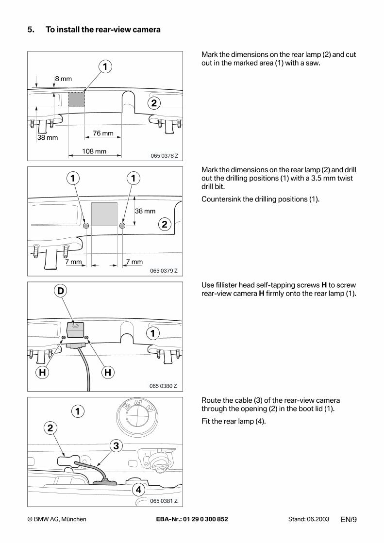
5. To install the rear-view camera
Mark the dimensions on the rear lamp (2) and cut out in the marked area (1) with a saw.
Mark the dimensions on the rear lamp (2) and drill out the drilling positions (1) with a 3.5 mm twist drill bit.
Countersink the drilling positions (1).
Use fillister head self-tapping screws H to screw rear-view camera H firmly onto the rear lamp (1).
Route the cable (3) of the rear-view camera through the opening (2) in the boot lid (1).
Fit the rear lamp (4).
065 0378 Z
76 mm38 mm
8 mm
108 mm
2
1
065 0379 Z
7 mm
38 mm
7 mm
2
1 1
065 0380 Z
1
H
D
H
065 0381 Z
1
4
3
2
EN/9© BMW AG, München EBA-Nr.: 01 29 0 300 852 Stand: 06.2003
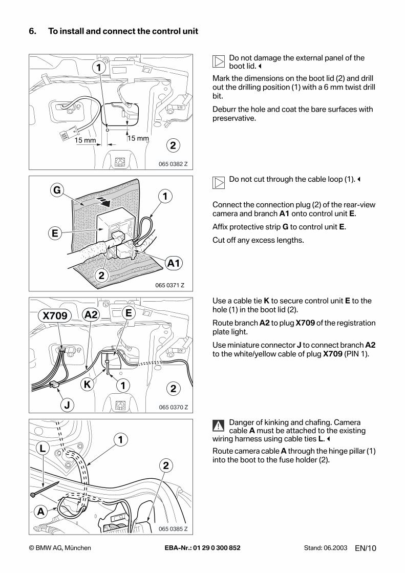
6. To install and connect the control unit
Do not damage the external panel of the boot lid.!
Mark the dimensions on the boot lid (2) and drill out the drilling position (1) with a 6 mm twist drill bit.
Deburr the hole and coat the bare surfaces with preservative.
Do not cut through the cable loop (1).!
Connect the connection plug (2) of the rear-view camera and branch A1 onto control unit E.
Affix protective strip G to control unit E.
Cut off any excess lengths.
Use a cable tie K to secure control unit E to the hole (1) in the boot lid (2).
Route branch A2 to plug X709 of the registration plate light.
Use miniature connector J to connect branch A2 to the white/yellow cable of plug X709 (PIN 1).
Danger of kinking and chafing. Camera cable A must be attached to the existing
wiring harness using cable ties L.!
Route camera cable A through the hinge pillar (1) into the boot to the fuse holder (2).
065 0382 Z
15 mm15 mm2
1
E
1
2
G
A1
065 0371 Z
065 0370 Z
21K
J
EX709 A2
065 0385 Z
L
A
2
1
!
EN/10© BMW AG, München EBA-Nr.: 01 29 0 300 852 Stand: 06.2003

7. To install the switchbox
Depending on the equipment in the car, there are two possible ways of installing switchbox F.!
Affix sealing strip M to the rear of switchbox F.
First possibility
Place switchbox F against the front base support system (1) and transfer two holes.
Drill through the front base support system (1) with a 3.5 mm twist drill bit.
Screw switchbox F on firmly using fillister head self-tapping screws I.
Second possibility
Place switchbox F against the holder (1) and transfer three holes.
Drill through the holder (1) with a 3.5 mm twist drill bit.
Screw switchbox F on firmly using fillister head self-tapping screws I.
065 0403 Z
F M
I
F
1
065 0383 Z
065 0384 Z
I
1
F
I
EN/11© BMW AG, München EBA-Nr.: 01 29 0 300 852 Stand: 06.2003

8. To install and connect the camera cable
Route camera cable A to the right side of the boot.
Route camera cable A to switchbox F.
Remove the draw-in tool (1).
Insulate branch A3, green cable, and branch A9, white cable, and tie them back.
Connect branches A4 � A6 to branch B1, blue plug, as follows:
- Branch A4, transparent cable, in PIN 24
- Branch A5, black/brown cable, in PIN 11
- Branch A6, black cable, in PIN 23
Connect branches A7 and A8 to branch B1, blue plug, as follows:
- Branch A7, red cable, with miniature connector J to branch B2, red cable (PIN 25)
- Branch A8, brown cable, with miniature connector J to branch B3, brown cable (PIN 12)
065 0372 Z
A
A 1
F065 0400 Z
065 0373 Z
A4-A6
B1
A3 A9
B1
4
A7-A8B2
J
065 0374 Z
B3
EN/12© BMW AG, München EBA-Nr.: 01 29 0 300 852 Stand: 06.2003
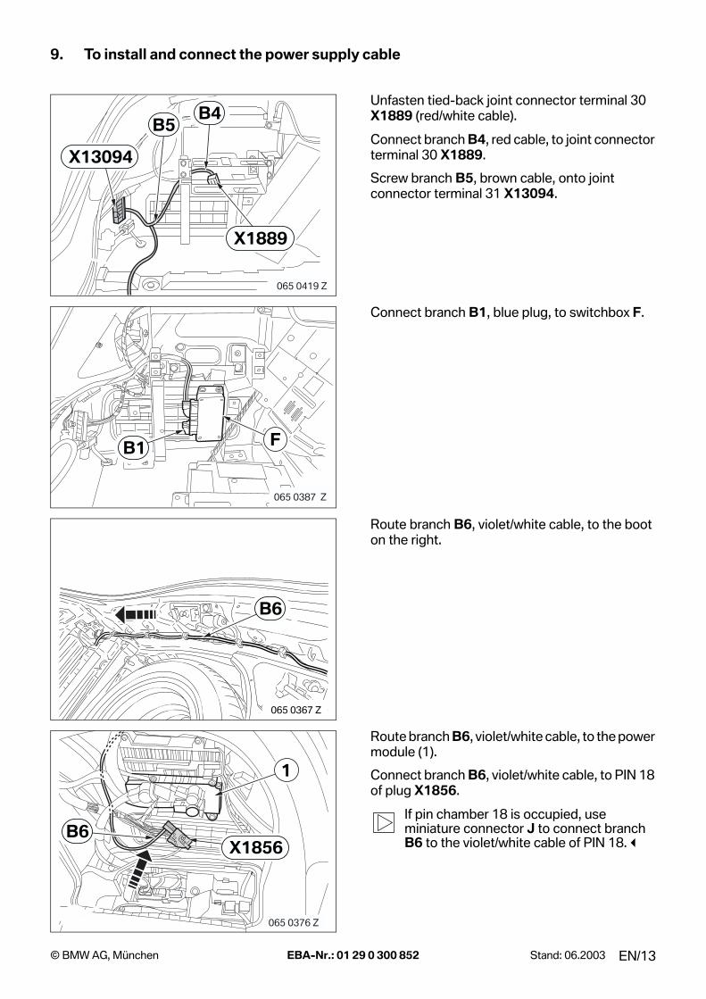
9. To install and connect the power supply cable
Unfasten tied-back joint connector terminal 30 X1889 (red/white cable).
Connect branch B4, red cable, to joint connector terminal 30 X1889.
Screw branch B5, brown cable, onto joint connector terminal 31 X13094.
Connect branch B1, blue plug, to switchbox F.
Route branch B6, violet/white cable, to the boot on the right.
Route branch B6, violet/white cable, to the power module (1).
Connect branch B6, violet/white cable, to PIN 18 of plug X1856.
If pin chamber 18 is occupied, use miniature connector J to connect branch B6 to the violet/white cable of PIN 18.!
X13094
X1889
B4B5
065 0419 Z
FB1
065 0387 Z
065 0367 Z
B6
1
X1856B6
065 0376 Z
EN/13© BMW AG, München EBA-Nr.: 01 29 0 300 852 Stand: 06.2003

10. To install and connect the adapter cable
Disconnect the following cables (1) from plug X1312 of the navigation computer (2):
- Red cable from PIN 3
- Green cable from PIN 4
- Blue cable from PIN 5
- Shield from PIN 13
Connect the disconnected cables into socket casing N as follows:
- Red cable in PIN 3
- Green cable in PIN 1
- Blue cable in PIN 2
- Shield in PIN 4
Connect branches C2 � C5 as follows to plugX1312 of the navigation computer (1):
- Branch C2, white/red cable, in PIN 3
- Branch C3, white/green cable, in PIN 4
- Branch C4, violet cable, in PIN 5
- Branch C5, shield, in PIN 13
Connect socket casing N to branch C6, blue plug.
Connect branch C1, natural colour plug, to switchbox F.
065 0388 Z
2
1 N
X1312
065 0389 Z
1
X1312
C2-C5
N
F
C6
C1
065 0390 Z
EN/14© BMW AG, München EBA-Nr.: 01 29 0 300 852 Stand: 06.2003

11. Concluding work and coding
This retrofit system does not require coding.
- Connect the battery
- Conduct a brief test
Check the function of the rear-view camera as follows:
- Switch on the ignition
- Deactivate the help texts in the Settings menu
- Select the Navigation menu
- Select full-screen display in the Navigation menu
- Engage reverse; an image must appear on the on-board monitor
- Disengage reverse gear
The on-board monitor must switch over after about 5 seconds.
- Re-assemble the car
EN/15© BMW AG, München EBA-Nr.: 01 29 0 300 852 Stand: 06.2003
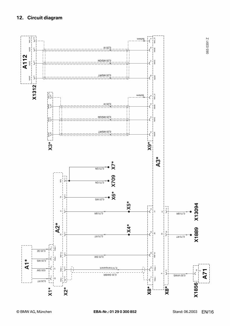
12. Circuit diagram
A1
12
NA
VR
06
5 0
39
1 Z
X1
85
6
X1
31
2
18
3 18
4 17
5 16
13
9
Schirm
A7
1
NA
VR
NA
VG
NA
VB
NA
V_3
1
X8
*
A3
*V
ideo
-
24
25
12
23
R
X2
*
X7
09
X6
*
0,75 RT x
0,75 BR x
0,25 SW x
0,35 SW/BR x
0,75 GN x
0,25 WS x
21
56
12
4
11
30
3
1R
SF
inv
Vid
eo +
Vid
eo -
RF
ST
A
30
31
RS
F in
vV
ideo
+
x
3
X7
*
NA
VB
NA
VG
NA
VB
NA
V_3
1N
AV
RN
AV
GN
AV
_31
0,35 WS/RT
0,35 WS/GN
0,35 VI
0,14 transparent
0,75 GN x
A1
*
X1
*035 SW
0,35 WS
0,35 GE
31
24
31
Vid
eo -
Vid
eo +
30
0,35 RTx
xx
x
3 15
1 14
2 13
4 6
Schirm
0,35 WS/RT
0,35 WS/GN
0,35 VI
NA
VR
NA
VG
NA
VB
NA
V_3
1
X3
*
X9
*
26
13
10
R
30
X1
88
9X
13
09
4
31
0,50 VI/WS x
0,75 RT x
0,75 BR x
X8
*
A2
*
X4
*X
5*
EN/16© BMW AG, München EBA-Nr.: 01 29 0 300 852 Stand: 06.2003

12. Circuit diagram
Legend
All the designations marked with an asterisk (*) apply only to these installation instructions or this circuit diagram
Cable colours
A1* Rear-view cameraA2* Control unitA3* Switchbox
A112 Navigation computerA71 Power module
X1* Black 4-pin socket casingX2* Black 12-pin socket casingX3* Blue 4-pin socket casingX4* Miniature connectorX5* Miniature connectorX6* Socket contactX7* Cable openX8* Blue 26-pin socket casingX9* 18-pin natural socket casing
X709 Blue 3-pin plugX1312 Black 20-pin plugX1856 Black 18-pin plugX1889 Terminal 30 joint connectorX13094 Terminal 31 joint connector
BL BlueBR BrownGE YellowGN GreenGR GreyRT RedSW BlackVI VioletWS White
EN/17© BMW AG, München EBA-Nr.: 01 29 0 300 852 Stand: 06.2003
Top Related