


Languages
Pages
Legal

Innovative Materials Testing Technologies, Inc.
1
2008 NDT Symposium Sponsored by Lockheed Martin NDT Working Group March 24-26, 2008
FG RFEC Technique for Thick Multilayer Aircraft Structures
Inspection
Part II Crack Detection
Yushi SunInnovative Materials Testing Technologies, Inc.
3141 W. Torreys Peak DriveSuperior, CO 80027Tel: 303 554 8000Fax: 303 554 8001
Email. [email protected]
Innovative Materials Testing Technologies, Inc.
2
2008 NDT Symposium Sponsored by Lockheed Martin NDT Working Group March 24-26, 2008
Part II – Deeply hidden crack detection
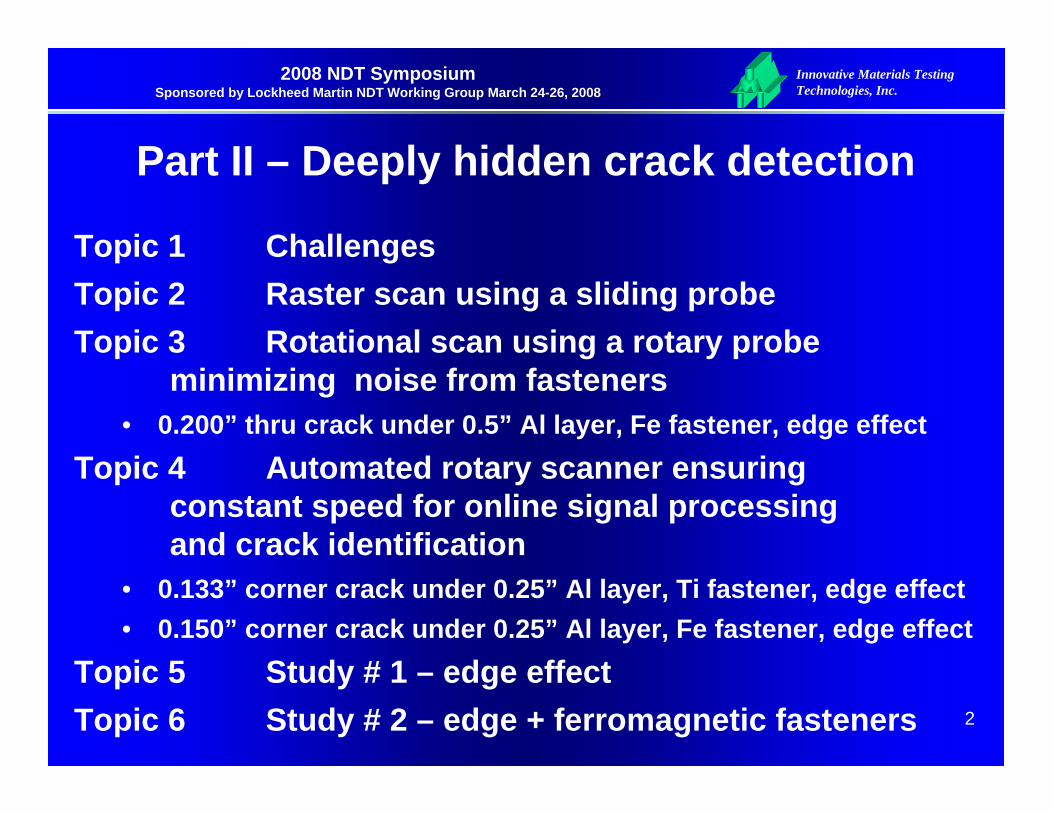
Topic 1 ChallengesTopic 2 Raster scan using a sliding probeTopic 3 Rotational scan using a rotary probe
minimizing noise from fasteners• 0.200” thru crack under 0.5” Al layer, Fe fastener, edge effect
Topic 4 Automated rotary scanner ensuring constant speed for online signal processing and crack identification
• 0.133” corner crack under 0.25” Al layer, Ti fastener, edge effect• 0.150” corner crack under 0.25” Al layer, Fe fastener, edge effect
Topic 5 Study # 1 – edge effectTopic 6 Study # 2 – edge + ferromagnetic fasteners
Innovative Materials Testing Technologies, Inc.
3
2008 NDT Symposium Sponsored by Lockheed Martin NDT Working Group March 24-26, 2008
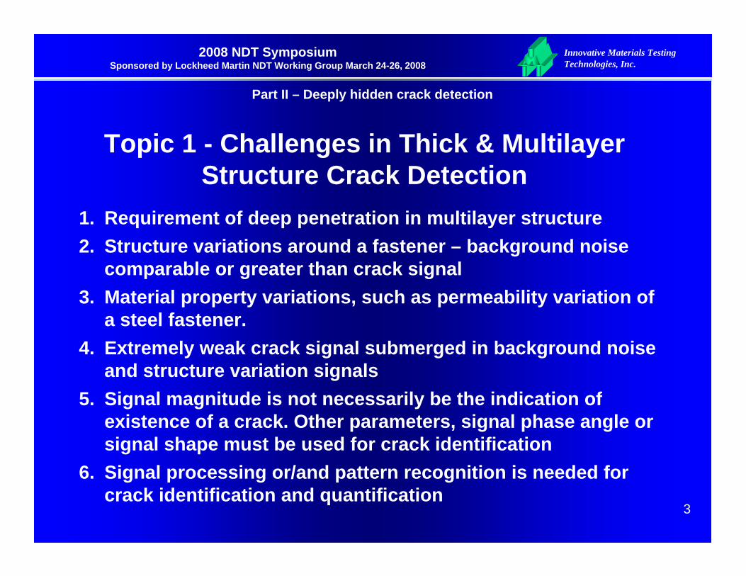
Topic 1 - Challenges in Thick & Multilayer Structure Crack Detection
1. Requirement of deep penetration in multilayer structure2. Structure variations around a fastener – background noise
comparable or greater than crack signal3. Material property variations, such as permeability variation of
a steel fastener.4. Extremely weak crack signal submerged in background noise
and structure variation signals5. Signal magnitude is not necessarily be the indication of
existence of a crack. Other parameters, signal phase angle or signal shape must be used for crack identification
6. Signal processing or/and pattern recognition is needed for crack identification and quantification
Part II – Deeply hidden crack detection

Innovative Materials Testing Technologies, Inc.
4
2008 NDT Symposium Sponsored by Lockheed Martin NDT Working Group March 24-26, 2008
Topic 2 - Raster Scan Using a Sliding Probe
A. Photos of FG RFEC Sliding Probes for Crack Detection
RF4 V3Footprint: 0.85” x 2.15”
Coil Center-to-Center Distance, CCD = 1.15”
RF2 V3Footprint: 0.3” x 0.62”
Coil Center-to-Center Distance, CCD = 0.3”
Part II – Deeply hidden crack detection

Innovative Materials Testing Technologies, Inc.
5
2008 NDT Symposium Sponsored by Lockheed Martin NDT Working Group March 24-26, 2008
Sliding Probe Example 1Detecting 2nd Layer Notches in 0.25” + 0.25” Thick
B-52 Wing Spar Structure
181716
Y
Xx5x1
14 Scan Area
15 19
Edge Cutx0
29 mmX – Scan direction
19.7 mm
Excitation coil
Pickup coilFastener
15 – 2nd layer notches (0.100” & 0.245”)16-17 – 1st layer notch18-19 – 2nd layer notch
Part II – Deeply hidden crack detection

Innovative Materials Testing Technologies, Inc.
6
2008 NDT Symposium Sponsored by Lockheed Martin NDT Working Group March 24-26, 2008
Detecting Crack in 0.25” + 0.25” Thick B-52 Wing Spar Structure
15: 2nd layer vertical notches (0.100” & 0.245”)
16-17: 1st layer
Other holes
f = 100 Hz, EFD = 19.7 mm
Part II – Deeply hidden crack detection

Innovative Materials Testing Technologies, Inc.
7
2008 NDT Symposium Sponsored by Lockheed Martin NDT Working Group March 24-26, 2008
Limitation of Sliding Probe Raster Scan -Strong Noise from Fasteners
Signal from deep crack submerged by noise
Part II – Deeply hidden crack detection
Innovative Materials Testing Technologies, Inc.
8
2008 NDT Symposium Sponsored by Lockheed Martin NDT Working Group March 24-26, 2008
Part II – Deeply hidden crack detection
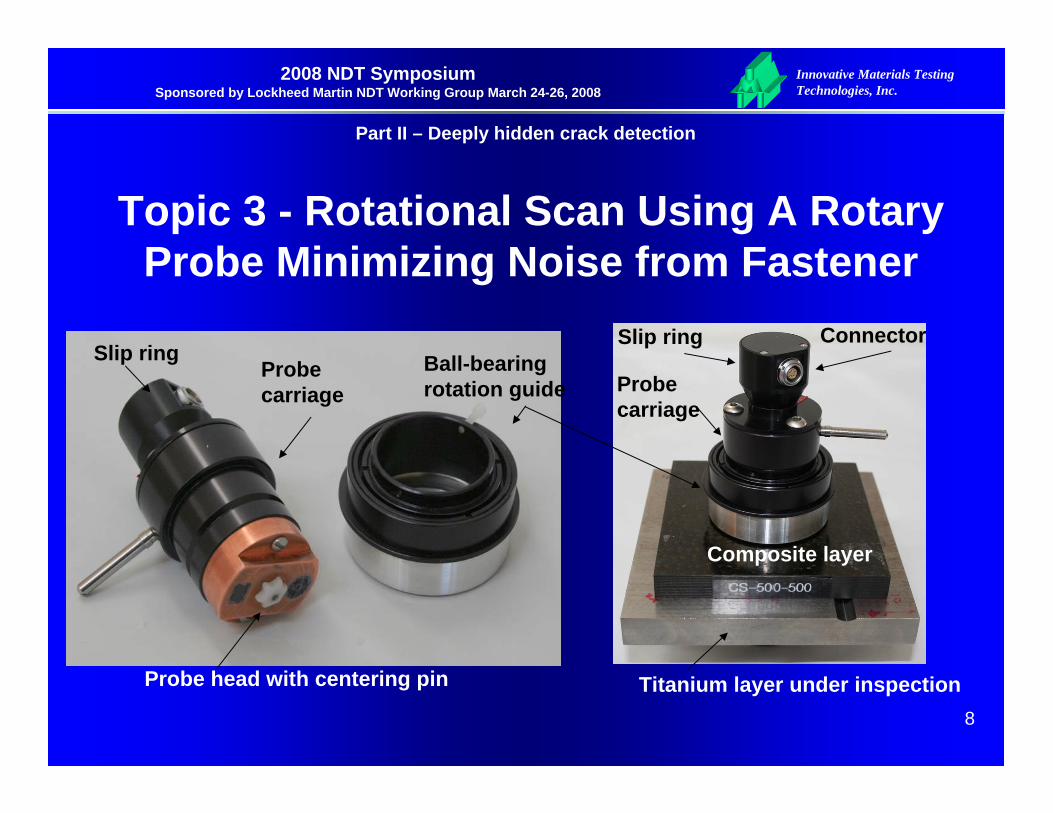
Topic 3 - Rotational Scan Using A Rotary Probe Minimizing Noise from Fastener
Ball-bearing rotation guide
Slip ring Connector
Probe carriage
Composite layer
Titanium layer under inspection
Slip ringProbe carriage
Probe head with centering pin

Innovative Materials Testing Technologies, Inc.
9
2008 NDT Symposium Sponsored by Lockheed Martin NDT Working Group March 24-26, 2008
Rotational Scan – Minimizing noise from fastener
Part II – Deeply hidden crack detection
-+ -+
Diff Sensors
Fastener- head Excitation Coil
Diff Sensors
Fastener- head Excitation Coil
Probe 2 – No signal unless there is a crack
FastenerSensor
Drive coil
FastenerSensor
Drive coil
Probe 1 – Constant signal unless there is a crack

Innovative Materials Testing Technologies, Inc.
10
2008 NDT Symposium Sponsored by Lockheed Martin NDT Working Group March 24-26, 2008
Success Example 1 Detecting Cracks in Raised-Head Fastener holes
Specimen
A pocket closely
matches fastener
head
FG RFEC Probe
Additional Guide for
Probe Rotation Test
Specimen
A round probe head serves as a guide for probe rotation
Part II – Deeply hidden crack detection

Innovative Materials Testing Technologies, Inc.
11
2008 NDT Symposium Sponsored by Lockheed Martin NDT Working Group March 24-26, 2008
0.100” rivet head overhang
Rotorcraft - Detection of Second Layer Cracks Topside
0
0.1
0.2
0.3
0.4
0.5
0.6
0.7
0.8
0.91
0 0.02 0.04 0.06 0.08 0.1 0.12
Flaw Length (in.)
Prob
abili
ty o
f Det
ectio
n
Phasec/Walking Probe Insp. #1 Phasec/Walking Probe Insp. # 2Phasec/Walking Probe Insp. # 3 Foerster-Rivet Check w/Custom ProbeRemote Field Eddy Current Concave Probe Insp. #1Concave Probe Insp. #2
Comparison of POD with other NDI TechniquesCarried out by FAA AANC, Sandia Labs
Part II – Deeply hidden crack detection

Innovative Materials Testing Technologies, Inc.
12
2008 NDT Symposium Sponsored by Lockheed Martin NDT Working Group March 24-26, 2008
Success Example 2 Detecting Lower Layer Cracks in Boeing 723 Lap-Joint
Part II – Deeply hidden crack detection
Innovative Materials Testing Technologies, Inc.
13
2008 NDT Symposium Sponsored by Lockheed Martin NDT Working Group March 24-26, 2008
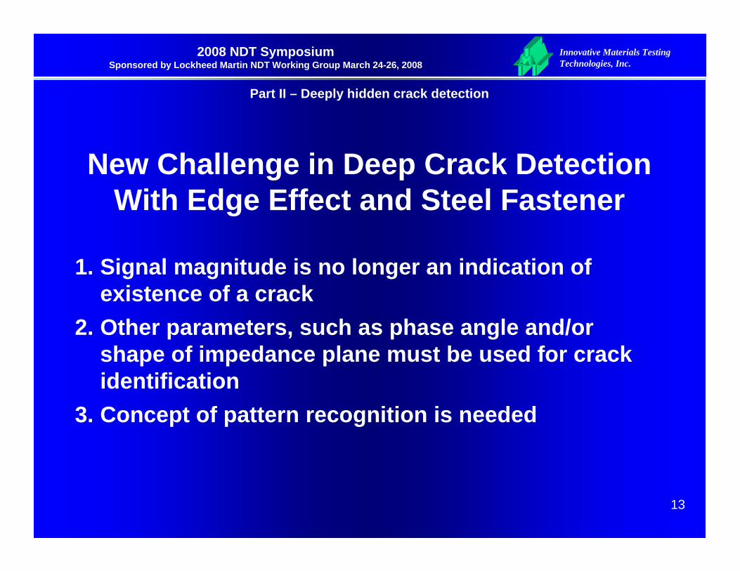
New Challenge in Deep Crack DetectionWith Edge Effect and Steel Fastener
1. Signal magnitude is no longer an indication of existence of a crack
2. Other parameters, such as phase angle and/or shape of impedance plane must be used for crack identification
3. Concept of pattern recognition is needed
Part II – Deeply hidden crack detection
Innovative Materials Testing Technologies, Inc.
14
2008 NDT Symposium Sponsored by Lockheed Martin NDT Working Group March 24-26, 2008
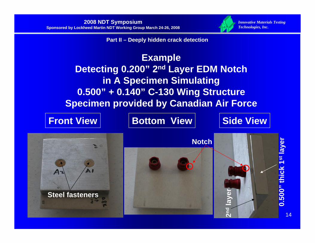
Example Detecting 0.200” 2nd Layer EDM Notch
in A Specimen Simulating0.500” + 0.140” C-130 Wing Structure
Specimen provided by Canadian Air Force
Notch
Steel fasteners
0.50
0” th
ick
1stla
yer
2nd
laye
r
Front View Bottom View Side View
Part II – Deeply hidden crack detection

Innovative Materials Testing Technologies, Inc.
15
2008 NDT Symposium Sponsored by Lockheed Martin NDT Working Group March 24-26, 2008
Topic 4- Rotational Scan: Result of the Example Crack free
Observation:In deep crack detection signal magnitude is no longer the indication of existence of a crack, other parameters, such as phase angle and/or shape of impedance plane must be used for crack identification. Concept of pattern recognition is needed.
Part II – Deeply hidden crack detection

Innovative Materials Testing Technologies, Inc.
16
2008 NDT Symposium Sponsored by Lockheed Martin NDT Working Group March 24-26, 2008
Step motor inside
Motor controller inside
Probe carriage
Probe head
Connectors
Probe carriage
Rotation guide with suction base
Ball bearing rotation guide with suction base
Probe head
Sealing rubber tube
Vacuum area
Topic 4 - Automated Rotary ScannerEnsuring Constant Speed for Online Signal
Processing & Crack Identification
Part II – Deeply hidden crack detection

Innovative Materials Testing Technologies, Inc.
17
2008 NDT Symposium Sponsored by Lockheed Martin NDT Working Group March 24-26, 2008
Computerized SSEC InstrumentEnabling Online Signal Processing
InstrumentSSEC II-S
Rotary Scanner
LaptopSpecimen
under inspection
Part II – Deeply hidden crack detection
Innovative Materials Testing Technologies, Inc.
18
2008 NDT Symposium Sponsored by Lockheed Martin NDT Working Group March 24-26, 2008
Topic 5 - Study # IEdge effect
Part II – Deeply hidden crack detection
Innovative Materials Testing Technologies, Inc.
19
2008 NDT Symposium Sponsored by Lockheed Martin NDT Working Group March 24-26, 2008
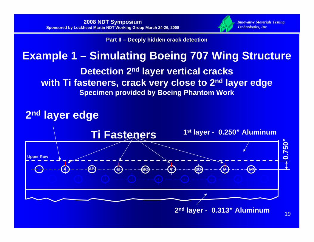
Example 1 – Simulating Boeing 707 Wing Structure Detection 2nd layer vertical cracks
with Ti fasteners, crack very close to 2nd layer edgeSpecimen provided by Boeing Phantom Work
A AB BC CD D0B C D
Upper Row
1st layer - 0.250” Aluminum
2nd layer - 0.313” Aluminum
0.75
0”
2nd layer edge
Ti Fasteners
Part II – Deeply hidden crack detection

Innovative Materials Testing Technologies, Inc.
20
2008 NDT Symposium Sponsored by Lockheed Martin NDT Working Group March 24-26, 2008
No EDM Notch
Increase of EDM Notch Size
0.200”X0.267” 0.220”X0.293” 0.250”X0.293” 0.300”X0.313”0.170”X0.227”0.150”X0.200”0.133”X0.173”0.100”X0.133”
Example 1 - Impedance plane & ellipse fitting2nd Layer Crack near 2nd Layer Edge Non-ferromagnetic Fastener
Observation: without signal processing reliably detected EDM notch size > 0.250”(L)
Part II – Deeply hidden crack detection

Innovative Materials Testing Technologies, Inc.
21
2008 NDT Symposium Sponsored by Lockheed Martin NDT Working Group March 24-26, 2008
* These are post-processing data. Real-time processing is also working, but more verification is needed.
Example 1 - Signal Rotation Angle2nd Layer Crack near 2nd Layer Edge Non-ferromagnetic Fastener
0 5 1 0 1 5-2 0
0
2 0
4 0
6 0
8 0
f a s te n e rs
angl
e (d
egre
e) S N R a t C : 3 .5 3ED M : 0 .1 5 0 " ( W ) x 0 .2 0 0 " ( D )
R o w : T L
A -
0.10
0”(L
)X0.
133”
(D)
B -
0.13
3”(L
)X0.
173”
(D)
C -
0.15
0”(L
)X0.
200”
(D)
D -
0.17
0”(L
)X0.
227”
(D)
E -0
.200
”(L)
X0.2
67”(
D)
F -0
.220
”(L)
X0.2
93”(
D)
G -
0.25
0”(L
)X0.
313”
(D)
H -
0.30
0”(L
)X0.
313”
(D)
AB
–N
o ED
M N
otch
D0
–N
o ED
M N
otch
EF –
No
EDM
Not
ch
FG –
No
EDM
Not
ch
GH
–N
o ED
M N
otch
BC
–N
o ED
M N
otch
CD
–N
o ED
M N
otch
H0
–N
o ED
M N
otch
Observation: with signal processingreliably detected EDM notch size ≥ 0.133”(L)
Part II – Deeply hidden crack detection
Innovative Materials Testing Technologies, Inc.
22
2008 NDT Symposium Sponsored by Lockheed Martin NDT Working Group March 24-26, 2008
Topic 5 - Study # 2
Edge + Ferromagnetic Fastener
Part II – Deeply hidden crack detection

Innovative Materials Testing Technologies, Inc.
23
2008 NDT Symposium Sponsored by Lockheed Martin NDT Working Group March 24-26, 2008
Example 2 – Simulating Boeing 707 Wing Structure Detection 2nd layer vertical cracks
with Steel fasteners, crack very close to 2nd layer edge
A AB BC CD D0B C D
Upper Row
1st layer - 0.250” Aluminum
2nd layer - 0.313” Aluminum
0.75
0”
2nd layer edge
Steel Fasteners
Part II – Deeply hidden crack detection

Innovative Materials Testing Technologies, Inc.
24
2008 NDT Symposium Sponsored by Lockheed Martin NDT Working Group March 24-26, 2008
Example 2Detection 2nd layer vertically aligned cracks
with steel fasteners & crack close to 2nd layer edge
Challenges:1. Unlike the case of Example 1 where the fasteners are made of
non-ferromagnetic material, in Example 3 the fastener is made of steel. In this particular case crack signal DECREASES with increase of notch size as shown in next page.
2. The underline physics of this phenomenon so far remains unknown.
3. A notch can not be identified by any single parameter of detected signal. A Shape Factor P, which is a combination of a few features of the shape of the impedance plane, is used for identification of a notch.
Part II – Deeply hidden crack detection
Innovative Materials Testing Technologies, Inc.
25
2008 NDT Symposium Sponsored by Lockheed Martin NDT Working Group March 24-26, 2008
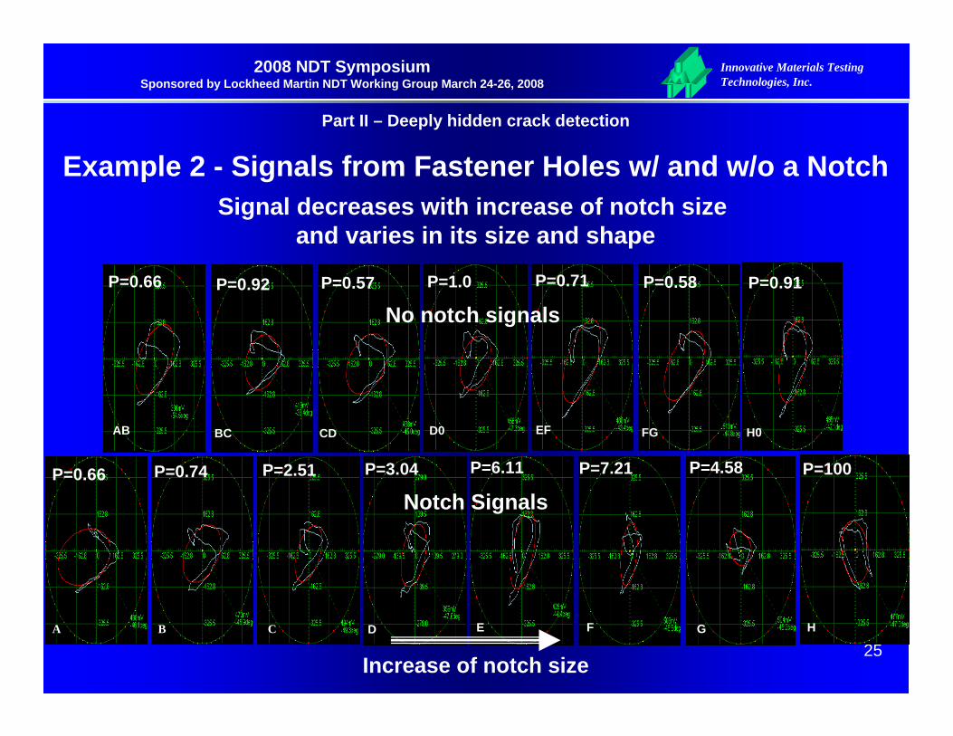
Example 2 - Signals from Fastener Holes w/ and w/o a NotchSignal decreases with increase of notch size
and varies in its size and shape
Part II – Deeply hidden crack detection
AB
P=0.66
BC
P=0.92
CD
P=0.57
EF
P=0.71
FG
P=0.58
H0
P=0.91
A
P=0.66
B
P=0.74
C
P=2.51
F
P=7.21
G
P=4.58
H
P=100
D0
P=1.0
D
P=3.04
E
P=6.11
No notch signals
Notch Signals
Increase of notch size

Innovative Materials Testing Technologies, Inc.
26
2008 NDT Symposium Sponsored by Lockheed Martin NDT Working Group March 24-26, 2008
0.2” EDM notch
Shape Factor P=6.11
without notch
Shape Factor P=0.57
Example 2 - Signals from Fastener Holes w/ and w/o a NotchSignal decreases with increase of notch size
and varies in its size and shape
Part II – Deeply hidden crack detection
Innovative Materials Testing Technologies, Inc.
27
2008 NDT Symposium Sponsored by Lockheed Martin NDT Working Group March 24-26, 2008
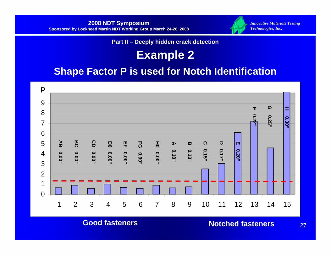
0123456789
10
1 2 3 4 5 6 7 8 9 10 11 12 13 14 15
Notched fastenersGood fasteners
C 0.15”
D 0.17”
E 0.20”
F 0.22”
G 0.25”
H 0.30”
P
B 0.13”
A 0.10”
AB
0.00”
BC
0.00”
CD
0.00”
D0 0.00”
EF 0.00”
FG 0.00”
H0 0.00”
Example 2Shape Factor P is used for Notch Identification
Part II – Deeply hidden crack detection

Innovative Materials Testing Technologies, Inc.
28
2008 NDT Symposium Sponsored by Lockheed Martin NDT Working Group March 24-26, 2008
Summary on Study #21. Signal obtained in detection 2nd layer vertically
oriented crack that is close to a 2nd layer edge has abnormal behavior. The signal decreases with the increase of 2nd layer crack size.
2. It is impossible to identify a crack using a conventional approach of signal processing and crack identification.
3. The concept of pattern recognition is utilized in this case.
4. Automated rotary RF_RFEC probe provides highly repeatable signal that enables the use of online signal processing and pattern recognition.
Part II – Deeply hidden crack detection
Top Related