


Languages
Pages
Legal


Paralex: An
Ozalp
ABSTRACT
Environment for Parallel Programming in
Distributed Systems*
labao~lu
Renzo
Lorenzo Alvisi Alessandro Amoroso
Davoli Luigi Alberto Giachini
Department of Mathematics
University of Bologna
Piazza Porta S. Donato, 5
40127 Bologna, Italy
Modern distributed systems consisting of powerful
workstations and high-speed interconnection networks
are an economical alternative to special-purpose su-
per computers. The technical issues that need to be
addressed in exploiting the parallelism inherent in a
distributed system include heterogeneity, high-latency
communication, fault tolerance and dynamic load bal-
ancing. Current software systems for parallel program-
ming provide little or no automatic support towards
these issues and require users to be experts in fault-
tolerant distributed computing. The Paralex system is
aimed at exploring the extent to which the parallel ap-
plication programmer can be liberated from the com-
plexities of distributed systems. Paralex is a complete
programming environment and makes extensive use of
graphics to define, edit, execute and debug parallel sci-
entific applications. All of the necessary code for dis-
tributing the computation across a network and repli-
cating it to achieve fault tolerance and dynamic load
balancing is automatically generated by the system. In
this paper we give an overview of Paralex and present
our experiences with a prototype implementation,
1 Introduction
There is general agreement that significant future
increases in computing power will be possible only
through exploiting parallelism. One of the many ad-
“This work was supported in part by the Commission of Eu-
ropean Communities under ESPRIT Programme Basic Research
Action Number 3092 (Predictably Dependable Computing Sys-
tems), the United States Office of Naval Research under contract
NOO014-91-J-1219, IBM Corporation and the Italian Ministry of
University, Research and Technology.
Permission to copy without fee sII or part of this material is
granted provided that the copies are not made or distributed for
direct commercial advantage, the ACM copyright notice and the
title of the publication and its date appear, and notice is given
that copying is by permission of the Association for Computing
Machinery. To copy otherwise, or to republish, requires a fee
and/or specific permission.ICS ‘92-7 /921D.C., USA
~ 1992 ACM 0-89791 -485-6/92 /0007 /0178 . ..$1 .50
vantages of distributed systems is their potential for
true parallel execution across multiple processing ele-
ments, In fact, the amount of raw computing power
that is present in a typical modern distributed system
with dozens, if not hundreds, of general-purpose work-
stations may be comparable to an expensive, special-
purpose super computer. Thus, it is tempting to try to
harness the massive parallelism available in these sys-
tems for single, compute-intensive applications. There
are, however, several obstacles that remain before net-
works of workstations can become ‘(a poor man’s super-
computer.”
Distributed systems differ from special-purpose par-
allel computers in that they (i) exhibit asynchrony with
respect to computation and communication, (ii) com-
municate over relatively low-bandwidth, high-latency
networks, (iv) lack architectural and linguistic homo-
geneity, (v) exhibit increased probability of communica-
tion and processor failures, and (vi) fall under multiple
administrative domains.
As a consequence, developing parallel programs in
such systems requires expertise not only in distributed
computing, but also in fault tolerance. A large number
of important applications (e.g., genome analysis) require
days or weeks of computations on a network with dozens
of workstations [14]. In these applications, many hours
of computation can be wasted not only if there are gen-
uine hardware failures, but also if one of the processors
is turned off, rebooted or disconnected from the net-
work. Given that the most common components of a
distributed system are workstations and that they are
typically under the control of multiple administrative
domains (typically individuals who “own” them), these
events are much more plausible and frequent than real
hardware failures.
We claim that current software technology for paral-
lel programming in distributed systems is comparable
to assembly language programming for traditional se-
quential systems — the user must resort to low-level
primitives to accomplish data encodingldecoding, com-
munication, remote execution, synchronization, failure
178
detection and recovery. It is our belief that reasonable
technologies already exist to address each of these prob-
lems individually. What remains a challenge is the task
of integrating these technologies in software support en-
vironments that permit easy development of reliable ap-
plications to exploit the parallelism and fault tolerance
offered by distributed systems.
The Paralex project has been undertaken to explore
the extent to which the parallel application program-
mer can be isolated from the complexities of distributed
systems. Our goal is to realize an environment that
will encompass all phases of the programming activity
and provide automatic support for distribution, fault
tolerance and heterogeneity in distributed and parallel
applications. Paralex makes extensive use of graphics
for expressing computations, controlling execution and
debugging. The programming paradigm supported by
Paralex promotes the view of parallel computations as
collages of ordinary sequential programs. The “glue”
necessary for combining computations consists of inter-
dependencies and data flow relations that are expressed
using a graphical notation. In the limit, interesting new
parallel programs can be constructed by reusing exist-
ing sequential software and without having to rewrite
a single line of traditional code. As such, Paralex also
addresses the issue of “software reusability” [10].
2 The Paralex Programming Paradigm
The choices made for programming paradigm and no-
tation are fundamental in harnessing parallelism in a
particular application domain [11]. The programming
paradigm supported by Paralex can be classified as
static data flow [1]. A Paralex program is composed
of nodes and links. Nodes correspond to computations
(functions, procedures, programs) and the links indi-
cate flow of (typed) data. Thus, Paralex programs can
be thought of as directed graphs (and indeed are visu-
alized as such on the screen) representing the data flow
relations plus a collection of ordinary sequential code
fragments to indicate the computations.
Unlike claasical data flow, nodes of a Paralex pro-
gram carry out significant computations. This so-called
large-grain data flow model [6] is motivated by the high-
latency, low-bandwidth network that is available for
communication in distributed systems. Only by keeping
the communication-to-computation ratio to reasonable
levels can we expect reasonable performance from par-
allel applications in such systems.
While extremely simple, the above programming
paradigm has several desirable properties. First, appli-
cation parallelism is explicit in its notation — all nodes
that have no data interdependencies can execute in par-
allel. Second, the small number of abstractions that
the programmer has to deal with are familiar from se-
quential programming. In particular, there are no new
linguistic constructs for communication or synchroniza-
tion. Finally, composing parallel programs by intercon-
necting sequential computations allows automatic sup-
port for heterogeneity and fault tolerance and facilitates
soft ware reuse as discussed in subsequent sections.
2.1 Computation Nodes
The basic computational unit of a Paralex program is
a multi-junction mapping some number of inputs to
outputs. The graphical representation for the multi-
function itself is a node and that of the inputs and out-
puts are incoming and outgoing links, respectively. The
semantics associated with this graphical syntax obeys
the so-called “strict enabling rule” of data-driven com-
putations in the sense that when all of the incoming
links contain values, the computation associated with
the node starts execution transforming the input data
to outputs. Paralex functions must be “pure” in that
they can have no side effects. In particular, persistent
internal state or interactions with external components
such as files, devices and other computations are not
permitted.
The actual specification of the computation may be
done using whatever appropriate notation is available,
including sequential programming languages such as C,
C++, Fortran, Pascal, Modula or Lisp 1. It is also pos-
sible for computations to be carried out through com-
piled binaries or library functions subject to architec-
tural compatibility as discussed in Section 3.3.
How multiple outputs are specified for multi-functions
depends on the language being used to program the
nodes. One possibility is to implement the functions as
procedures and return results through call-by-reference
parameters. Another possibility is to use simple func-
tions and pack multiple results into composite data
types such as structures, records or arrays. We pursue
this option in the next section.
2.2 Filter Nodes
Filters permit multi-functions to be implemented using
simple functions. They allow the single (structured) re-
sult to be picked apart to produce multiple outputs. In
this manner, subsets of the data produced by the func-
tion may be sent to different destinations in the com-
putation graph. This is a principal paradigm for data-
parallel computing. For example, a single large matrix
produced by some node in the computation may be “fil-
tered” by extracting each of the quadrants to produce
four sub-matrixes to be processed in parallel at the next
level.
1 The exact list of programming languages permissible for node
computations is determined by type and calling convention com-
patibility with C
179
Conceptually, filters are defined and manipulated just
as regular nodes and their “computations” are specified
through sequential programs. In practice, however, all
of the data filtering computations are executed in the
context of the single process that produced the data
rather than as separate processes. Associating filters
with the producer of the data not only saves network
bandwidth, it also economizes on data buffers necessary
at the consumers.
elettra spare, SunOS, rel=4, rev=l, fpu, gfxn2, specG21
xenia spare, SunOS, rel=4, rev=l, fpu, spec=13
fyodor spare, SunOS, rel=4, rev=l, fpu, gfx, spec=10
nabucco mips, fpu, gfx, color, spec=18
tosca m68020-Sun OS, SunOS, rel=4, rev=O, fpu, spec=9
violetta m68020-A/UX, spec=5
turandot RS6000, AIX, fpu, spec=12
carmen vax, gfx, memory= 16, spec=6
jago fyodor
2.3 Subgraph Nodes
Paralex computation graphs may be structured hier-
archically. Any node may contain a graph structure
rather than sequential code to carry out its computa-
tion. These sulrgraph nodes obey the same semantics as
primitive multi-function nodes and may be further de-
composed themselves. Subgraphs are to Paralex what
procedures are to sequential programs — a structur-
ing abstraction that renders programs not only easier
to understand, but also easier to construct using pre-
programmed components.
2.4 Cycle Nodes
At the inter-node level, Paralex computation graphs are
acyclic. Any single node of the graph, however, can
be invoked repetitively during execution as long as its
outputs match (in number and type) exactly its inputs.
The termination condition for the cycle can be dynamic
as it is defined explicitly by the user as a function of the
node inputs.
The Paralex cycle construct has a “while-loop” se-
mantics and operates as follows. If the termination
function evaluates to false, the node computation is
skipped and the input values appear as output. Oth-
erwise, the outputs produced by the node computation
are “wrapped around” and become inputs for the next,
iteration. While the cycle is active, external input to
tile node is blocked.
3 Overview of Paralex
Paralex consists of four logical components: A gral)ljlcs
editor for program development, a compiler. an exec u-
tor aud a runtime support environment The first t II ree
comrjonents are in[egratmi within a single graphical ]Jro-
gra!uliling enviroril~ie]~t. It is, however, possible to edit,
(’ollll)ll~ or eX(3CUt,f ~’iMalFX prO~riiJTIS dSO frOl”ll IllaC])i I IFS
WI(II 110 graphics support, II) this section we illust ritl e
MJI]I<-,of the principal ollaracterisLics of the user interface
i Ill ougb example.,.
3.1 Site Definition
The distributed systel)l 011 wllicb Paralex is to rllll is
cleiined through a iIlc ( allt,d paralex site. Tills iilv
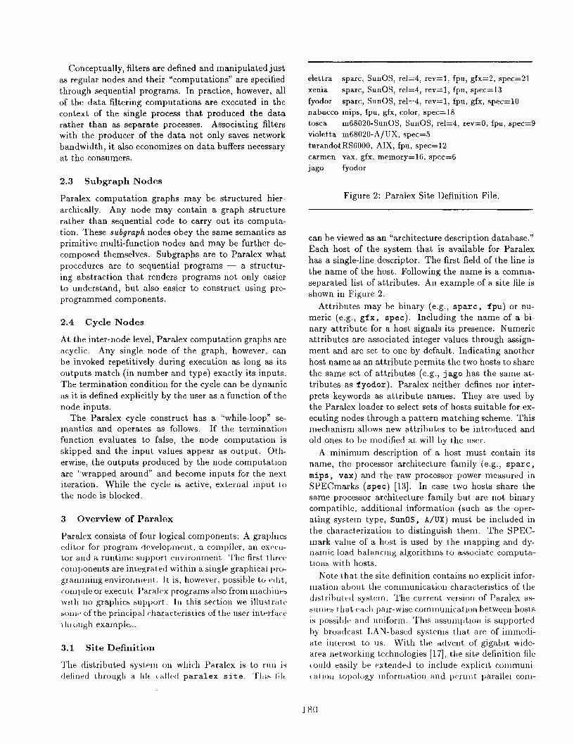
Figure 2: Paralex Site Definition File,
can be viewed as an “architecture description database.”
Each host of the system that is available for Paralex
has a single-line descriptor. The first field of the line is
the name of the host. Following the name is a comma-
separated list of attributes. An example of a site file is
shown in Figure 2.
Attributes may be binary (e.g., spare, fpu) or nu-
meric (e.g., gfx, spec). Including the name of a bi-
nary attribute for a host signals its presence, Numeric
attributes are associated integer values through assign-
ment and are set to one by default. Indicating another
host name as an attribute permits the two hosts to share
the same set of attributes (e.g., j ago has the same at-
tributes as f yodor). Paralex neither defines nor inter-
prets keywords as attribute names. They are used by
the Paralex loader to select sets of hosts suitable for ex-
ecuting nodes through a pattern matching scheme. This
mechanism allows new attributes to be introduced and
old ones to be modified at will by the user.
A minimum description of a host must contain its
name, the processor architecture family (e.g., spare,
mips, vax) and the raw processor power measured in
SPECmarks (spec) [13]. In case two hosts share the
same processor architecture family but are not binary
compatible, additional information (such as the oper-
ating system type, SunOS, A/UX ) must be included in
the chrrracterizatioll to distinguish them. The SPEC-
mark value of a host is used by the Inapping and dy-
nalriic load balancing algorithms to associate computa-
tlous with hosts.
Note t]] at the site definition contains no explicit infor-
rnatio]l abol]t the communication characteristics of the
distributt,d systeln. The current velsion of Paralex as-
sulllc~ t hat vach pair-wise communicant u-m between hosts
is possil)lv and uniform. This assumljt,ron is supported
by broadcast LAN-based systenls that are of immedi-
ate interest to us. With the dvent ot’ gigabit wide-
area Iletworliing technologies [17], the site definition file
~ould easily be exteuded to include expliclt communi-
( atlojl Lopology information and pfirlll]t parallel coni-
180
puting over non-uniform and long-haul
networks.
3.2 The Graphics Editor
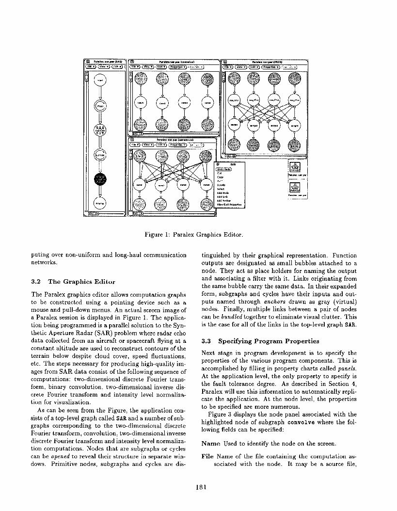
Figure 1: Paralex Graphics Editor.
communication
The Paralex graphics editor allows computation graphs
to be constructed using a pointing device such as a
mouse and pull-down menus. An actual screen image of
a Paralex session is displayed in Figure 1, The applica-
tion being programmed is a parallel solution to the Syn-
thetic Aperture Radar (SAR) problem where radar echo
data collected from an aircraft or spacecraft flying at a
constant altitude are used to reconstruct contours of the
terrain below despite cloud cover, speed fluctuations,
etc. The steps necessary for producing high-quality im-
ages from SAR data consist of the following sequence of
computations: two-dimensional discrete Fourier trans-
form, binary convolution, two-dimensional inverse dis-
crete Fourier transform and intensity level normaliza-
tion for visualization.
As can be seen from the Figure, the application con-
sists of a top-level graph called SAR and a number of sub-
graphs corresponding to the two-dimensional discrete
Fourier transform, convolution, two-dimensional inverse
discrete Fourier transform and intensity level normaliza-
tion computations. Nodes that are subgraphs or cycles
can be opened to reveal their structure in separate win-
dows. Primitive nodes, subgraphs and cycles are dis-
tinguished by their graphical representation. Function
out-puts are designa~ed ‘as small bubbles attached to a
node, They act as place holders for naming the output
and associating a filter with it, Links originating from
the same bubble carry the same data. In their expanded
form, subgraphs and cycles have their inputs and out-
puts named through anchors drawn as gray (virtual)
nodes. Finally, multiple links between a pair of nodes
can be bundled together to eliminate visual clutter. This
is the case for all of the links in the top-level graph SAR.
3.3 Specifying Program Properties
Next stage in program development is to specify the
properties of the various program components, This is
accomplished by filling in property charts called panels.
At the application level, the only property to specify is
the fault tolerance degree. As described in Section 4,
Paralex will use this information to automatically repli-
cate the application. At the node level, the properties
to be specified are more numerous.
Figure 3 displays the node panel associated with the
highlighted node of subgraph convolve where the fol-
lowing fields can be specified:
Name Used to identify the node on the screen.
File Name of the file containing the computation as-
sociated with the node. It may be a source file,
181

11-
)1,.F4
cmm
t
e,.lnm
9yJ“.,,4 ,,.
0,,!!,.,
9 %04, Fropm !,.
N,nl. c0n”2
File <*”.1.4 <m
I.dud. $81 h m
LlbrMv
Head,, (am! Wmvol”mrwlx mat <0”st 2)
WI. L* I,I!. I . . . . .
O*PW $1,. WN/PARbLLELi5M
Obl D,tiow K“.. N(SUrOSw -1.3))
Prelmm,d $ u
Node Tvm Functlm [ Simrm ] CWE(Subwmh)
T,d at!., - -wok.+ dir, /.mUBv.dW.z.ldP. P.dP.”1.
a@D@ED@5MW1”d,<!, dlo. h>h{wl.d. bath, h>
(,* Point4Y-@nt ,wwlvtim of the <“W ad 4at* mtrt x=o second mr$mter indicates Wch strip w we wking tith
& x .C.nwlwtit, s)~%1g, m,c
[(Wlstw {“t { , j,ml” d.ta[N/PMAL1f L15Ml[N]:
road.data(d,ta, ,),?., [i -0, i ‘ N/wm11EL15H. I*)
‘“’(’ -0’ ‘ <‘; i-’.at[{l(jl - OllP .Wltipl,(mt [11[j], .ia Ca[ll [j]):retur”(nat),
)
pm orotitof two [email protected] .tiw ‘/
<*1*Wml,x.mlt, vly(a, b)~glstw ml. a. b:
,,gi, ter <ml. !mu;
MP, ... r.obro-a.m ‘b)mtm.1. - *,{. . b,r, ... c, . b.lmr,c”r”(tenv),
1
“01 d-r..d.dst.(d.t..s,,!,)<mol. dUil[H/P.W16LLC LlSR1 [N];!“? st,l D:,
FILE -W, %<, %mn<);WI <t,, 1“, f, 1.
fw - fqen[,lusrlulozal pl%arldataf,eal ., . ,.):m . fnmn .lusrf.!oz*l Plsar/dattiImg,.ar ., r.),
[ [f,oak[fw. lmg)(.t, !P.(N, N/PMALLEL15W,s z,of[flmt)). 0>fseck[fP~ . [l Mg)(,t, !P. (N,N/PMALLE1lW.,{ Z60f(P1.St)). 0>F., c, . 0; I * wwtmrw. w]
for[j .0: j ‘N, j+!) ,dam[ll[j .,, - <tlmt154t<(tOr1:dati
Note that the code is ordinary sequential C and con- 3.5 Executing Paralex Programs
tains nothing having to do with remote communication,
synchronization or fault tolerance.
The attributes of a filter are specified and edited ex-
actly in the same manner as an ordinary node through
a panel associated with the output bubble. The only
difference is that most of the fields in the filter panel
are inherited from the parent node and are not modi-
fiable, Finally, a link panel is used to name the input
parameter of the destination function that is to receive
the data value.
3.4 Compiling Paralex Programs
Once the user has fully specified the Paralex program by
drawing the data flow graph and supplying the compu-
tations to be carried out by the nodes, the program can
be compiled. The textual representation of the Paralex
program along with all of the source code for the node
computations are fed as input to the compiler. Although
the compiler may be invoked manually as a command,
it is typically invoked from the graphical interface where
the program was composed.
The first pass of the Paralex compiler is actually a
precompiled to generate all of the necessary stubs to
wrap around the node computations to achieve data
representation independence, remote communication,
replica management and dynamic load balancing. Type
checking across links is also performed in this phase.
Currently, Paralex generates all of the stub code as or-
dinary C. As the next step, a collection of standard
compilers are invoked: C compiler for the stubs, per-
haps others for the node computations. For each node,
the two components are linked together to produce an
executable module.
The compiler must also address the two aspects of
heterogeneity — data representation and instruction
sets. Paralex uses the ISIS toolkit [9] as the infrastruc-
ture to realize a universal data representation. All data
that is passed from one node to another during the com-
putation are encapsulated as ISIS messages. Paralex
automatically generates all necessary code for encoding-
decoding basic data types (integer, real, character) and
linearizing arrays of these basic types. The user must
supply routines to linearize all other data types.
Heterogeneity with respect to instruction sets is han-
dled by invoking remote compilations on the machines
of interest and storing multiple executable for the
nodes. Versions of the executable code corresponding
to the various architectures are stored in subdirectories
(named with the architecture class) of the current pro-
gram. A network file server that is accessible by all of
the hosts acts as the repository for the executable.
The Paralex executor consists of a loader, controller and
debugger. The debugger is incorporated into the graph-
ical interface and uses the same display as the editor. It
is described in [5]. The loader takes the output of the
compiler and the textual representation of the computa-
tion graph as input and launches the program execution
in the distributed system. As with the compiler, the
loader can be invoked either manually as a command or
through the graphical interface.
Before a Paralex program can be executed, each of
the nodes (and their replicas, in case fault tolerance
is required) must be associated with a host of the dis-
tributed system. Intuitively, the goals of this mapping
problem are to improve performance by maximizing par-
allel execution and minimizing remote communication,
to distribute the load evenly across the network, and
to satisfy the fault tolerance and heterogeneity require-
ments. Since an optimal solution to this problem is
computationally intractable, Paralex bases its mapping
decisions on simple heuristics described in [4].
The units of our mapping decision are chains de-
fined as sequences of nodes that have to be executed
sequentially due to data dependence constraints. The
initial mapping decisions, as well as modifications dur-
ing execution, try to keep all nodes of a chain mapped
to the same host. Since, by definition, nodes along a
chain have to execute sequentially, this choice minimizes
remote communication without sacrificing parallelism.
Each node is executed as a Unix process that contains
both the computation for the node and all of its associ-
ated filters.
4 Fault Tolerance
One of the primary characteristics that distinguishes a
distributed system from a special-purpose super com-
puter is the possibility of partial failures during com-
putations. As noted earlier, these may be due to real
hardware failures or, more probably, as consequences
of administrative interventions. To render distributed
systems suitable for long-running parallel computations,
automatic support for fault tolerance must be provided.
The Paralex run-time system contains the primitives
necessary to support fault tolerance and dynamic load
balancing.
As part of the program definition, Paralex permits
the user to specify a fault tolerance level for the compu-
tation graph. Paralex will generate all of the necessary
code such that when a graph with fault tolerance k is
executed, each of its nodes will be replicated at k + 1
distinct hosts to guarantee success for the computation
despite up to k failures. Failures that are tolerated are
of the benign type for processors (i.e., all processes run-
ning on the processor simply halt) and communication
183

Figure 4: Replication and Group Communication for Fault Tolerance.
components (i.e., messages may be lost). There is no
attempt to guard against more malicious processor fail-
ures nor against failures of non-replicated components
such as the network interconnect.
Paralex uses passive replication as the basic fault tol-
erance technique. Given the application domain (par-
allel scientific computing) and hardware platform (net-
works of workstations), Paralex favors efficient use of
computational resources over fast recovery times in the
presence of failures. Passive replication not only satis-
fies this objective, it provides a uniform mechanism for
dynamic load balancing through late binding of compu-
tations to hosts as discussed in Section 5.
Paralex uses the ISIS coordinator-cohort toolkit to im-
plement passive replication. Each node of the compu-
tation that requires fault tolerance is instantiated as a
process group consisting of replicas for the node. One
of the group members is called the coordinator in that it
will actively compute. The other members are cohorts
and remain inactive other than receiving broadcasts ad-
dressed to the group. When ISIS detects the failure of
the coordinator, it automatically promotes one of the
cohorts to the role of coordinator.
Data flow from one node of a Paralex program to an-
other results in a broadcast from the coordinator of the
source group to the destination process group, Only the
coordinator of the destination node will compute with
the data value while the cohorts simply buffer it in an
input queue associated with the link. When the coordi-
nator completes computing, it broadcasts the results to
the process groups at the next level and signals the co-
horts (through another intra-group broadcast) so that
they can discard the buffered data item corresponding
to the input for the current invocation. Given that Par-
alex nodes implement pure functions and thus have no
internal state, recovery from a failure is trivial — the
cohort that is nominated the new coordinator simply
starts computing with the data at the head of its input
queues.
Figure 4 illustrates some of these issues by consider-
ing a 3-node computation graph shown at the top as an
example, The lower part of the figure shows the pro-
cess group representation of the nodes based on a fault
tolerance specification of 2. Arrows indicate message
arrivals with time running down vertically. The gray
process in each group denotes the current coordinator.
Note that in the case of node A, the initial coordinator
fails during its computation (indicated by the X). The
process group is reformed and the right replica takes
over as coordinator. At the end of its execution, the co-
ordinator performs two broadcasts. The first serves to
communicate the results of the computation to the pro-
cess group implementing node C and the second is an
internal group broadcast. The cohorts use the message
of this internal broadcast to conclude that the current
buffered input will not be needed since the coordina-
tor successfully computed with it. Note that there is a
small chance the coordinator will fail after broadcasting
the results to the next node but before having informed
the cohorts. The result of this scenario would be multi-
ple executions of a node with the same (logical) input.
This is easily prevented by tagging each message with
184

an iteration number and ignoring any input messages
with duplicate iteration numbers.
The execution depicted in Figure 4 may appear de-
ceptively simple and orderly. In a distributed system,
other executions with inopportune node failures, mes-
sage losses and event orderings may be equally possible.
What simplifies the Paralex run-time system immensely
is structuring it on top of ISIS that guarantees “virtual
synchrony” with respect to message delivery and other
asynchronous events such as failures and group mem-
bership changes. Paralex cooperates with ISIS toward
this goal by using a reliable broadcast communication
primitive that respects causality [19].
6 1 ,
4-way +——8-way -+--
5.05 , *,
~-- .,,.- ~..
+-~”’ . . .,’ ~.
a 4. . .
{’ . . .4 1’ s.,00 ,/’ s.
‘.42 3 -’ f
, 2.7
,’)’
2
1 1!
64 128 256 512 1024
5 Dynamic Load Balancing
To achieve failure independence, each member of a
process group representing a replicated node must be
mapped to a different host of the distributed system.
Thus, the computation associated with the node can be
carried out by any host where there is a replica. To
the extent that nodes are replicated for fault tolerance
reasons, this mechanism also allows us to dynamically
shift the load imposed by Paralex computations from
one host to another.
As part of stub generation, Paralex produces the ap-
propriate ISIS calls so as to establish a coordinator for
each process group just before the computation proper
commences. The default choice for the coordinator will
be as determined by the mapping algorithms at load
time, This choice, however, can be modified later on by
the Paralex run-time system based on changes observed
in the load distribution on the network. This situation is
depicted in Figure 4 where the coordinator for the pro-
cess group representing node C is switched from the left
(default) to the right replica just before execution be-
gins. By delaying the establishment of a coordinator to
just before computation, we effectively achieve dynamic
binding of nodes to hosts, to the extent permitted by
having replicas around.
Perhaps the most dramatic effects of our dynamic
load balancing scheme are observed when the compu-
tation graph is executed not just once, but repetitively
on different input data. This so-called “pipelined oper-
ation” offers further performance gains by overlapping
the execution of different iterations [5]. Whereas be-
fore, the nodes of a chain executed strictly sequentially,
now they may all be active simultaneously working on
different instances of the input.
6 Performance Results
The Synthetic Aperture Radar application described in
Section 3.2 was compiled and run on a network of Sun-
4/60 (SparcStation 1) hosts, each with 16 Megabytes of
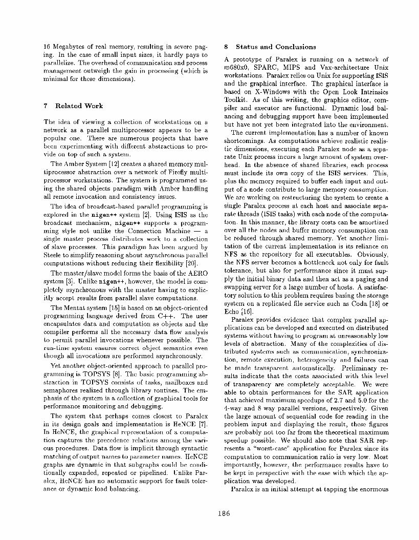
Input Dimension
Figure 5: SAR Speedup for 4-way (5 Processors) and
8-way (9 Processors) Parallelism.
real memory. The communication medium was a stan-
dard 10-Megabit Ethernet connecting several hundred
other hosts typical of an academic installation.
Experiments were performed to compare the perfor-
mance of the 4- and 8-way parallel implementations of
SAR with that of a sequential version coded in C. The
resulting speedup is displayed in Figure 5 as a func-
tion of the input dimension ranging from 64 x 64 to
1024 x 1024 matrixes. The experiments were conducted
with the hosts configured and running as if in normal
use but with no external users logged in. The hosts
involved in the experiment were not isolated from the
rest of the network, which continued to serve the normal
Departmental traffic. The program was run with fault
tolerance set to zero, thus disabling replication and pro-
hibiting the possibility for dynamic load balancing. The
mapping for the parallel executions were as follows: the
input and output (display) nodes mapped to one host
while the internal nodes, grouped into vertical chains,
mapped to a different host associated with that chain.
This resulted in the 4- and the 8-way parallel implemen-
tations using 5 and 9 hosts, respectively.
The results confirm our expectations — the larger
the data size, the more significant the speedup. The
fact that performance degrades for the largest input
size is totally an artifact of thrashing due to paging.
Note that in the case of a 1024 x 1024 image, the input
data (radar signal and filter matrixes of complex num-
bers with 8 bytes per entry) amount to more than 16
Megabytes. Furthermore, even in the parallel versions,
the input and output nodes are strictly sequential and
have to process the entire radar signal and gray-scale
matrixes, respectively. As a consequence, the host to
which they are mapped has to support a demand for
virtual memory significantly greater than the available
185
16 Megabytes of real memory, resulting in severe pag-
ing. In the case of small input sizes, it hardly pays to
parallelize. The overhead of communication and process
management outweigh the gain in processing (which is
minimal for these dimensions).
7 Related Work
The idea of viewing a collection of workstations on a
network as a parallel multiprocessor appears to be a
popular one. There are numerous projects that have
been experimenting with different abstractions to pro-
vide on top of such a system.
The Amber System [12] creates a shared memory mul-
tiprocessor abstraction over a network of Firefly multi-
processor workstations, The system is programmed us-
ing the shared objects paradigm with Amber handling
all remote invocation and consistency issues.
The idea of broadcast-based parallel programming is
explored in the nigen++ system [2]. Using ISIS as the
broadcast mechanism, nigen++ supports a program-
ming style not unlike the Connection Machine — a
single master process distributes work to a collection
of slave processes. This paradigm has been argued by
Steele to simplify reasoning about asynchronous parallel
computations without reducing their flexibility [20].
The master/slave model forms the basis of the AERO
system [3]. Unlike nigen++, however, the model is com-
pletely asynchronous with the master having to explic-
itly accept results from parallel slave computations.
The Mentat system [15] is based on an object-oriented
programming language derived from C++. The user
encapsulates data and computation as objects and the
compiler performs all the necessary data flow analysis
to permit parallel invocations whenever possible. The
run-time system ensures correct object semantics even
though all invocations are performed asynchronously.
Yet another object-oriented approach to parallel pro-
gramming is TOPSYS [8]. The basic programming ab-
straction in TOPSYS consists of tasks, mailboxes and
semaphores realized through library routines. The em-
phasis of the system is a collection of graphical tools for
performance monitoring and debugging.
The system that perhaps comes closest to Paralex
in its design goals and implementation is HeNCE [7].
In HeNCE, the graphical representation of a computa-
tion captures the precedence relations among the vari-
ous procedures. Data flow is implicit through syntactic
matching of output names to parameter names. HeNCE
graphs are dynamic in that subgraphs could be condi-
tionally expanded, repeated or pipelined. Unlike Par-
alex, HeNCE has no automatic support for fault toler-
ance or dynamic load balancing.
8 Status and Conclusions
A prototype of Paralex is running on a network of
m680x0, SPARC, MIPS and Vax-architecture Unix
workstations. Paralex relies on Unix for supporting ISIS
and the graphical interface, The graphical interface is
based on X-Windows with the Open Look Intrinsic
Toolkit. As of this writing, the graphics editor, com-
piler and executor are functional. Dynamic load bal-
ancing and debugging support have been implemented
but have not yet been integrated into the environment.
The current implementation has a number of known
shortcomings. As computations achieve realistic realis-
tic dimensions, executing each Paralex node as a sepa-
rate Unix process incurs a large amount of system over-
head. In the absence of shared libraries, each process
must include its own copy of the ISIS services. This,
plus the memory required to buffer each input and out-
put of a node contribute to large memory consumption.
We are working on restructuring the system to create a
single Paralex process at each host and associate sepa-
rate threads (ISIS tasks) with each node of the computa-
tion. In this manner, the library costs can be amortized
over all the nodes and buffer memory consumption can
be reduced through shared memory. Yet another limi-
tation of the current implementation is its reliance on
NFS as the repository for all executable. Obviously,
the NFS server becomes a bottleneck not only for fault
tolerance, but also for performance since it must sup-
ply the initial binary data and then act as a paging and
swapping server for a large number of hosts. A satisfac-
tory solution to this problem requires basing the storage
system on a replicated file service such as Coda [18] or
Echo [16] .
Paralex provides evidence that complex parallel ap-
plications can be developed and executed on distributed
systems without having to program at unreasonably low
levels of abstraction. Many of the complexities of dis-
tributed systems such M communication, synchroniza-
tion, remote execution, heterogeneity and failures can
be made transparent automatically. Preliminary re-
sults indicate that the costs associated with this level
of transparency are completely acceptable. We were
able to obtain performances for the SAR application
that achieved maximum speedups of 2.7 and 5.0 for the
4-way and 8-way parallel versions, respectively. Given
the large amount of sequential code for reading in the
problem input and displaying the result, these figures
are probably not too far from the theoretical maximum
speedup possible. We should also note that SAR rep-
resents a “worst-case” application for Paralex since its
computation to communication ratio is very low. Most
importantly, however, the performance results have to
be kept in perspective with the ease with which the ap-
plication was developed.
Paralex is an initial attempt at tapping the enormous
186

parallel computing resource that a network of work-
stations represents. Further experience is necessary to
demonstrate its effectiveness as a tool to solve real prob-
lems.
Acknowledgements Giuseppe Serazzi and his group
at the University of Milan contributed to early dis-
cussions on the mapping and dynamic load balancing
strategies. Ken Birman and Keshav Pingali of Cornell
University were helpful in clarifying many design and
implementation issues. Dave Forslund of Los Alamos
provided valuable feedback on an early prototype of the
system, Alberto Baronio, Marco Grossi, Susanna Lam-
bertini, Manuela Prati, Alessandro Predieri and Nicola
Samoggia of the Paralex group at Bologna contributed
to the various phases of the coding. We are grateful to
all of them.
REFERENCES
[1] W. B. Ackerman. Data Flow Languages. IEEE
Computer, February 1982, pp. 15-22.
[2] R. Anand, D. Lea and D. W. Forslund. Using
nigen++. Technical Report, School of Computer
and Information Science, Syracuse University, Jan-
uary 1991.
[3] D. P. Anderson. The AERO Programmer’s Manual.
Technical Report, CS Division, EECS Department,
University of California, Berkeley, October 1990.
[4] O. Babao~lu, L. Alvisi, A. Amoroso and R. Davoli.
Mapping Parallel Computations onto Distributed
Systems in Paralex. In Proc. IEEE CompEuro ’91
Conference, Bologna, Italy, May 1991.
[5] O. Babao@u, L. Alvisi, A. Amoroso, R. Davoli
and L. A. Giachini. Run-time Support for Dynamic
Load Balancing and Debugging in Paralex, Depart-
ment of Computer Science, Technical Report TR
91-1251, Cornell University, Ithaca, New York, De-
cember 1991,
[6] R. G. Babb II. Parallel Processing with Large-
Grain Data F1OW Techniques. IEEE Computer-,
July 1984, pp. 55-61.
[7] A. Beguelin, J. J. Dongarra, G. A. Geist, R.
Manchek and V. S. Sunderam. Graphical Develop-
ment Tools for Network-Based Concurrent Super-
computing. In Proc. Supercompuiing ’91, Novem-
ber 1991, Albuquerque, New Mexico.
[8] T. Bemmerl, A. Bode, et al. TOPSYS – Tools for
Parallel Systems. SFB-Bericht 342/9/90A, Tech-
nische Universitat Miinchen, Munich, Germany,
January 1990.
[9] K. Birman and K. Marzullo. ISIS and the META
Project. Sun Technology, vol. 2, no, 3 (Summer
1989), pp. 90-104.
[10] J. C. Browne, T. Lee and J. Werth. Experimental
Evaluation of a Reusability-Oriented Parallel Pro-
gramming Environment. IEEE Trans. on Software
Engtneertng, vol. 16, no. 2, February 1990, pp. 111-
120,
[11] N. Carriero and D. Gelernter. How to Write Par-
allel Programs: A Guide to the Perplexed. ACM
Computing Surveys, vol. 21, no. 3, September 1989,
pp. 323-358.
[12] J. S. Chase, F. G. Amador, E. D. Lazowska, H.
M. Levy and R. J. Littlefield. The Amber Sys-
tem: Parallel Programming on a Network of Multi-
processors. University of Washington, Department
of Computer Science Technical Report 89-04-01,
April 1989,
[13] K. Dixit. Speculations: Defining the SPEC
Benchmark. Sun Tech Journal, vol. 4, no. 1, Jan-
uary 1991, pp. 53–65.
[14] E. Fairfield. Private communication. Los Alamos
National Laboratory, New Mexico.
[15] A. S. Grimshaw. An Introduction to Parallel
Object-Oriented Programming with Mentat. Tech-
nical Report No. TR-9 1-07, Department of Com-
puter Science, University of Virginia, April 1991.
[16] A, Hisgen, A. Birrell, C. Jerian, T. Man, M,
Schroeder and G. Swart. Granularity and Seman-
tic Level of Replication in the Echo File System,
In Proc. Workshop on Management of Replicated
Data, Houston, IEEE CS Press 2085, November
1990, pp. 5-1o.
[17] IEEE Special Report. Gigabit Network Testbeds.
IEEE Computer, vol. 23, no. 9, September 1990,
pp. 77-80.
[18] J. Kistler and M, Satyanarayanan. Disconnected
Operation in the Coda File system. In Proc. 13th
ACM Symposium on Operating Systems Principles,
Asilomar, Pacific Grove, California, October 1991.
[19] L. Lamport. Time, clocks and the ordering of
events in a distributed system. Communications of
the ACM, vol. 21, no. 7, July 1978, pp. 558-565.
[20] G. L. Steele Jr. Making Asynchronous Parallelism
Safe for the World. In. Proc. 17th Annual ACM
Symposium on Principles of Programming Lan-
guages, 1990, pp. 218-231.
187
Top Related