


Languages
Pages
Legal


Para la instalación, manejo y mantenimiento de la máquina es necesario leer minuciosamente las instrucciones It is absolutely necessary to read carefully the following instructions for the installation handling and maintenance of the machine Vor Inbetriebnahme ist es unbedingt erforderlich, die nachstehenden Bedienungsanleitungen eingehend zu studieren Il est absolutement necessaire de lire avec attention les instructions données pour l’installation, manoeuvre et entretien de la machine
Modelo/Model/Modell/Modèle
Nº de la máquina/Machine number/Maschinen-Nr/Nº de la machine
Potencia motor/Machine power/Motorleistung/Puissance moteur
Voltaje/Voltage/Spannung/Voltage
Fecha de verificación/Verification date/Abnahmedatum/Date de verification
CLIENTE/CUSTOMER/KUNDE/CLIENT
NOTA IMPORTANTE/ IMPORTANT NOTE/ WITCHIGE HINWEISE/ AVIS IMPORTANT
Para piezas de recambio es necesario señalar:/ It is necessary to state for spare parts: Für die entsprechenden Ersatzteile muss folgendes angegeben werden:/ Pour pièces de rechange il est necessaire de mentioner:
- Modelo de máquina/ Machine model/ Maschinenmodell/ Modèle de machine - Nº de máquina/ Machine number/ Machinen-Nr./ Numéro de machine - Nº de pieza/ Piece reference/ Ersatzteil-Nr./ Reference de la pièce
CONSTRUCCIONES MECANICAS ERLO, S.A. - P.O. BOX 19 - 20720 AZKOITIA (SPAIN)
Tel. (34) /943.851858 - Fax: (34) 943.85 71 28 E-mail: [email protected]

TS-32/35 1IMPORTANTE: Antes de hacer la instalación se deberá de leer detenidamente este libro de instrucciones.
PAUTAS A SEGUIR
• Manipulación y Transporte de la Máquina. • Puesta en servicio. • Utilización y reglaje. • Operaciones de Mantenimiento y Reparación más importantes.
DESCRIPCION DE DICHAS PAUTAS
• MANIPULACION Y TRANSPORTE DE LA MAQUINA.
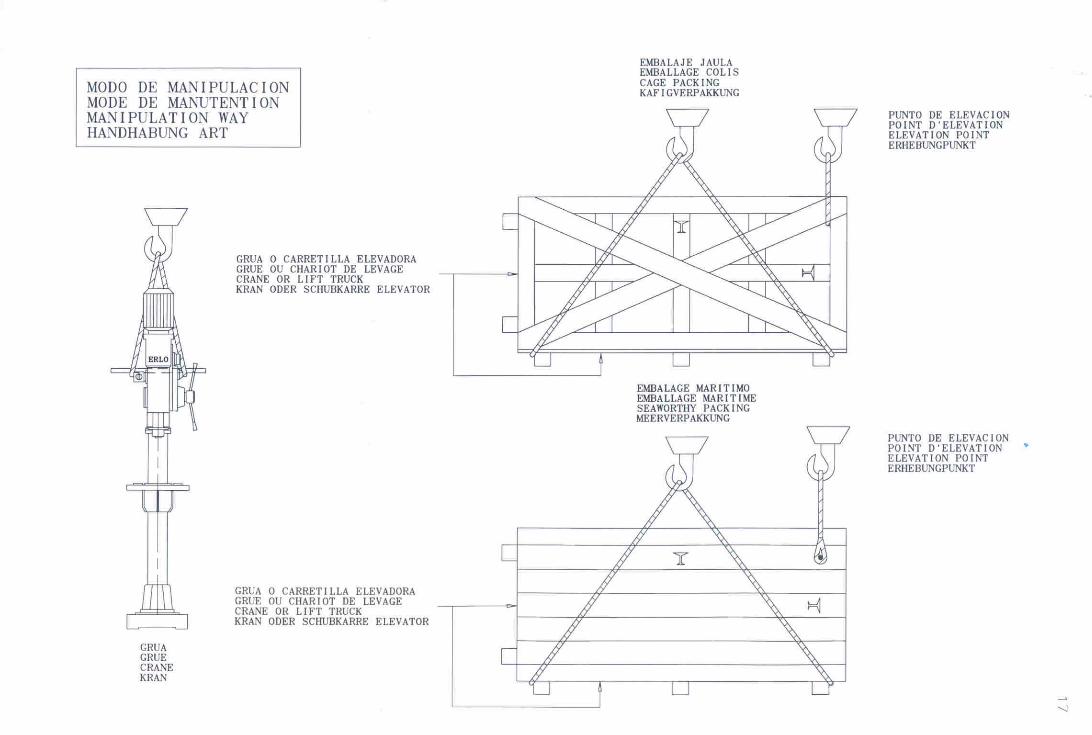
La manipulación de la máquina desde el suelo al medio de transporte y desde el medio de transporte al suelo o a otro medio de transporte, se efectúa con grúas y elementos auxiliares de elevación, que deben tener capacidad de carga suficiente, incluyendo los coeficientes de seguridad reglamentarios, para manipular la carga con seguridad. En este mismo libro de instrucciones se indica como se tienen que hacer las operaciones de manipulación. (Ver hoja modo manipulación página 13).
• PUESTA EN SERVICIO.
La instalación de la máquina se efectuará en un local protegido de las inclemencias del tiempo y en lugar idóneo con relación al proceso productivo. El suelo tendrá la capacidad de carga suficiente para soportar el peso de la máquina, además tendrá la suficiente rigidez para soportar la máquina sin deformaciones inadmisibles que impidan el correcto funcionamiento de la misma, además se deberán impedir que las vibraciones generadas durante el trabajo de la máquina se transmitan al suelo o a la estructura del local. Deberá preverse una superficie suficiente para facilitar el trabajo de la máquina, la manipulación del material, el mantenimiento de la máquina y el paso del personal. Para la puesta en servicio de la máquina, se deberá tener en cuenta lo siguiente: • El personal que efectúe los trabajos de puesta en servicio debe estar adecuadamente formado y utilizar en
caso necesario las prendas de protección y las herramientas adecuadas en aquellos trabajos que tenga que efectuar bajo tensión.
• La superficie mínima necesaria con y sin mesas auxiliares que se requieren para que pueda desarrollarse correctamente el trabajo de la máquina y se pueda efectuar el mantenimiento y la reparación de forma fácil y segura.
• Los datos de las fundaciones y de los sistemas antivibratorios que requiere (página 7). • La tensión de alimentación. • Asegurarse que la corriente que se va a utilizar, coincide con el voltaje del taladro. • En las máquinas de conexión trifásica se han de conectar los cables a las bornas TIERRA, RST y N, si
necesitara (N= Neutro). • Comprobar que el sentido de giro del eje principal y de la bomba de refrigeración (si llevara) es el correcto
según indica la placa de mandos.
• UTILIZACION Y REGLAJE
1. Colocación de la herramienta.
Asegurarse siempre que la máquina está parada. Se sujeta con la mano derecha el mando de bajada del eje y con la mano izquierda se introduce en el cono del eje la herramienta mediante un golpe seco, teniendo en cuenta que la lengüeta de la herramienta y el alojamiento del eje para dicha lengüeta estén en posición correcta. Deberá también tenerse en cuenta que las máquinas que lleven expulsor automático de brocas, tanto al introducir la herramienta como al estar la máquina trabajando en automático o en manual el seguro del expulsor, deberá estar introducido en la parte interior o en la posición "A". S/dibujo adjunto nº 2 (página 4).
2. Regulación de la altura de la mesa y giro conjunto soporte.
Desbloquear los mandos de blocaje nº 10 (página 7) del soporte de la mesa y con el mando de desplazamiento vertical del soporte columna nº 14 (página 7), regular la altura de la mesa. Bloquear de nuevo los mandos de blocaje nº 10 (página 7) del soporte de la mesa.
3. Regulación de la inclinación del brazo giratorio de la mesa. (Equipamiento extra).
Aflojar las tres tuercas nº 22 (página 7) y regular la inclinación del brazo giratorio según los grados necesarios e indicados en la regla graduada del brazo giratorio.

TS-32/35 2Una vez terminada la regulación, volver a apretar las tres tuercas.
4. Regulación giro mesa. (Equipamiento extra).
Desbloquear el mando de blocaje nº 21 (página 7) del brazo giratorio y regular el giro de la mesa. Bloquear de nuevo el mando de blocaje nº 21 (página 7) del brazo giratorio.
Advertencia: Asegurarse de que durante los procesos de trabajo los mandos y tornillos de blocaje estén bloqueados.
5. Cambio de velocidades.
Los mandos señalados con el nº 3 (página 7) son los que se utilizan para cambiar las velocidades. Las diferentes velocidades se indican en las placas situadas al lado de estos mandos. Es importante que antes de hacer un cambio de velocidades se asegure que el eje está completamente parado para no dañar los engranes de transmisión.
6. Profundidad de taladrado.
Para regular la profundidad de taladrado, aflojar el tornillo de blocaje nº 5 (página 7) y girar el mando regulador del índice de profundidad nº 18 en un sentido u otro. La flecha indicadora nº 12 (página 7), nos indicará en mm. o pulgadas, la profundidad de taladrado. Una vez terminada la regulación, volver a apretar el tornillo de blocaje nº 5 (página 7).
7. Expulsor automático de la herramienta.
Tirar del mando nº 3 y colocar en la posición "B", s/dibujo nº 2 (página 4), sujetar con la mano izquierda la herramienta y con la mano derecha dar un golpe seco en sentido horario con el mando nº 2 (página 4) en la parte superior del recorrido del eje principal. S/dibujo adjunto nº 3 (página 4).
Advertencia: Es importante que el mando nº 3 (página 4) esté siempre en la posición "A", para las operaciones de trabajo. (Ver dibujo nº 2).
• AVERIAS MÁS COMUNES
Rotura del muelle de recuperación.
Quitar la tapa de protección y extraer el muelle para la reposición, colocar el extremo central del muelle en la ranura del eje y sujetando el otro extremo del muelle con una mordaza Grip, hacerla girar en sentido antihorario hasta conseguir la tensión adecuada, una vez esto, introducir el tornillo en el alojamiento de sujeción del muelle. S/dibujo adjunto nº 1 (página 4)
• MANTENIMIENTO
Los trabajos de mantenimiento consisten en el engrase manual o semiautomático de los diferentes mecanismos, la forma de efectuarlos y la periodicidad de las mismas está indicado en este libro de instrucciones (página 5 y 6).
Operaciones que puedan ocasionar algún nivel de riesgo.
Taladrado.
• Todas las piezas a mecanizar como los elementos de sujeción deberán estar siempre bien amarrados a la mesa de trabajo.
• Todos los mandos de sujeción de soporte, mesa y columna deberán estar siempre bien bloqueados. • Se deberán tener en cuenta siempre todas las placas indicadoras de peligro. • El mando del dispositivo del expulsor automático de la herramienta deberá estar siempre en la posición "A",
s/dibujo nº 2 (página 4). • Se deberá tener siempre en cuenta, tanto trabajando en avance manual como en automático, los posibles
golpes que pueda ocasionar el mando nº 4 (página 7) debido a la energía elástica del muelle de recuperación del eje principal.
Reparación y mantenimiento.
Todas las operaciones de reparación y mantenimiento, han de realizarse por personal capacitado y tomando las medidas de seguridad pertinentes.
• DEPOSITO DE REFRIGERANTE
La base del taladro se utiliza como depósito de refrigerante, que tiene una capacidad de:
TSR.32 / TSR.35 / TSAR.32 / TSER.32 7 litros

TS-32/35 1IMPORTANT: Before starting with the installation, you should read this operation handbook carefully.
STEPS TO FOLLOW
• Machine handling and transport • Machine start-up. • Operation and adjustment. • Most important maintenance and repairs operations.
DESCRIPTION OF THE ABOVE STEPS
• MACHINE HANDLING AND TRANSPORT.
Machine handling from floor-transport-floor or another transport, is carried out with suitable cranes and lifting auxiliary items, which must assure enough loading capacity to lift the load safely. This handbook also shows how the handling operations must be performed (see page 13).
• MACHINE START-UP.
The machine should be installed in a place, which is protected against inclement weather. The foundation should have enough capacity to support the weight of the machine and it should also be tough enough to support the machine without inadmissible deformations, which prevent the correct function of the machine. Besides you should avoid the transmission of any vibration to the floor or structure of the place. You should provide enough room around the machine to ease the operation, handling of materials, machine maintenance and staff safety. Before the start up of the machine, please note the following: • Skilled workers, equipped with the correct clothing and tools should carry out the start-up. • Make sure that the machine has enough space with or without auxiliary tables to allow and ease the safe,
working, and maintenance and repair operations. • Ensure that the machine foundation and vibration proof system is adequate (page 7) • Check the supply voltage. • Make sure that the current to be used is the same as the drilling voltage. • On machines with three phase connection, the connection should be EARTH, RST and if required N
(N=Neutral). • Test that the main spindle and the coolant pump (it is has) are running in the correct direction, as per
indicated on the command plate.
• OPERATION AND ADJUSTMENT
1. TOOL SETTING.
Always make sure that the machine is stopped. Grip the spindle downward command with the right hand and with the left hand insert the tool into the spindle taper with a dead blow. Take into account that the tool releasing tongue and the shaft housing are in the correct position. As per drawing nº2 (page 4).
2. TABLE SUPPORT HEIGHT AND TURNING ADJUSTMENT.
Unlock the locking command nº10 (page 7) of the table support and with command of table support vertical displacement nº14 (page 7) adjust the table height. Lock again the locking commands nº10 (page 7) of the table support. Advise: Make sure that during the working process all the locking commands and screws are well locked.
3. TABLE ROTATING ARM INCLINATION ADJUSTMENT (Extra equipment).
Loosen the three nuts nº22 (page 7) and adjust the rotating arm inclination, as per the necessary degrees, which are shown in the arm ruler. Once finished the adjustment, loosen again the three nuts.
4. TABLE TURNING ADJUSTMENT (Extra equipment).
Unlock the locking command nº21 (page 7) of the rotating arm and adjust the table rotation. Lock again the locking command nº21 (page 7) of the rotating arm.
5. SPEEDS CHANGE.
The commands shown with nº3 (page 7) are the ones that we use to change the speeds. The different speeds are shown in the plates placed at one side of these commands. Advise: Before the speed change, make sure that the spindle is completely stopped.
6. DRILLING DEPTH
To adjust the drilling depth, loosen the locking screw nº5 (page 7) and turn the adjusting command of the depth index nº18 in one or another direction. The indexing arrow nº12 (page 7), will show us in millimetres or inches the drilling depth. Once the regulation is over, retighten the locking nuts nº5 (page 7).

TS-32/35 27. AUTOMATIC TOOL EJECTOR.
Pull from command nº3 and place in “B” position, as per drawing nº2 (page 4), adjust the tool with your left hand and with your right hand give a dead blow in clockwise sense with command nº2 (page 4). Advise: It is important that the command nº3 is always in “A” position for working operations. (See drawing nº2 page 4).
• MORE COMMON FAILURES
BREAKAGE OF THE RETURN SPRING.
Remove the protection cover and withdraw the spring for its replacement, place the central end of the spring in the shaft slot, holding the other end with a Grip vice. Rotate the grip vice in the anticlockwise direction until the suitable tension is obtained. After this, introduce the screw in the spring holding housing, as per drawing nº1 (page 4).
• MAINTENANCE
The maintenance of the machine consists in the manual or semi-automatic lubrication of the different mechanisms. This handbook shows the way and the frequency to carry out the lubrication (page 5 and 6).
OPERATIONS THAT CAN CAUSE SOME KIND OF RISK.
DRILLING.
• All the pieces to be machines as well as the holding items should always be well secured to the working table.
• The locking command of the head should always be well locked. • The danger indicating plates should always be taken into account. • The automatic tool ejector device command should always be in “A” position as per drawing nº2 (page 4). • Take special care with command nº9 (page 7) when it returns, due to the elastic energy of the return spring
of the main spindle.
REPAIR AND MAINTENANCE.
All the repair and maintenance operations, must be carried out by skilled staff and taking the necessary safety measures.
• COOLANT TANK
The base of the drilling machine is used as a coolant tank, with a capacity of: TS.32/35 7 litres TSAR.32/35 7 litres TSER.32/35 7 litres

DIBUJO 1
DRAWING
MORDAZA GRIP VICE
DIBUJO 2DRAWING 2
DIBUJO 3
DRAWING 3
4
O.K
O K
2
3
A
B

TS-32
723550
470
9
0
0
0
0
0
0
0
0
0
0
0
0
0
0
1
1
4
3
1
1
1
5
1
1
2
3
1
0
TS-32/35ENGRASEGREASING
SCHMIRUNGGRAISSAGE

INSTRUCCIONES DE ENGRASE GREASING INSTRUCTIONS
INSTRUCTIONS DE GRAISSAGE SCHMIERPLAN
1. Punto de engrase semanal. Engrase por aceite (con engrasador) Weekly greasing point. Oil greasing (with greaser) Point de graissage chaque semaine. Graissage par huile (avec graisseur) Wöchentliche fettschmierstelle. Delschierung (mit Schmiernippel)
2. Punto de engrase 48 horas. Engrase por aceite (con engrasador) Greasing point every 48 hours. Oil greasing (with greaser) Point de graissage chaque 48 heures. Graissage par huile (avec graisseur) Fettschmierstelle alle 48 styden. Delschierung (mit Schmiernippel)
3. Punto de engrase semanal. Engrase por grasa (a mano) Weekly greasing point. Greasing by grease (by hand) Point de graissage chaque semaine. Graissage par huile (a la main) Wöchentliche fettschmierstelle. Fettschmierung (mit der hand)
4. Punto de engrase semanal. Engrase por aceite (a mano con movimiento del soporte) Weekly greasing point. Oil greasing (by hand with support movement) Point de graissage chaque semaine. Graissage par huile (a la main avec mouvement du support) Wöchentliche fettschmierstelle. Fettschmierung (mit der hand beim haltersbewegen)
5. Engrase caja de mecanismos (cambio de aceite anual). Gearbox greasing (oil tobe changed yearly). Graissage boîte de mecanismes (changement d’huile annuel). Schmierung des Spindelkopfes (Der Olwechsel ist järlirfich unter der Voraussetzung del einschichtigen Betriebes).
Capacidad/Capacity/Capacité/Fassungsvolumen Cabezal / Headstock / Poupée / Kopfstuck
TS.32/TS.35/TSA.32/TSA.35/TSE.32/TSE.35 1 l TS.25/TS.30/TSA.25/TSA.30/TF.30 2.75 l TC.25/TC.30/TC.32/TC.35/ TCA.60/TCA.70/TCA.60BV/TCA.70BV 5 l TCA.25/TCA.30/TCA.32/TCA.35/TF.35 8 l V.40/V.45/TCA.40/TCA.45/TCA.50/TCA.45BV 4 l
Caja desplazamiento cabezal / Headstock displacement box / Boîte de deplacement de la poupée / Totverschiebung Dose
TCA.45BV/TCA.60BV/TCA.70BV 7 l TF.30/TF.35/TCA.35BV 0.5 l
Punto 1-2-4 Viscosidad mm2/seg (cst) a 40ºC, DIN 51.519-10±1. Simbolo DIN 51502 Point 1-2-4 Viscosity mm2/seg (cst) to 40ºC, DIN 51.519-10±1. Symbol as DIN 51.502 Punto 5 Viscosidad mm2/seg (cst) a 40ºC, DIN 51.519-68±6.8. Simbolo DIN 51502 Point 5 Viscosity mm2/seg (cst) to 40ºC, DIN 51.519-68±6.8. Symbol as DIN 51.502 Punto 3 Grasa. Penetración –265/295. Consistencia NLGI-2. Simbolo DIN 51502 Point 3 Grease. Penetration –265/295. Consistency NLGI-2. Symbol as DIN 51.502
SUMINISTRADOR SUPPLIER
Punto 1, 2 y 4 Point 1, 2 and 4
Aceite - Oil
Punto 5 Point 5
Aceite - Oil
Punto 3 Point 3
Grasa - Grease
Aral-Vitam GF 10 Aral-Degol BG 68 Aralub-HL-2
BP-Energol HLP-D 10 BP-Energol-GR-XP 68 BP-Energol Grease LS-2
Nuto H-10 Spartan EP 68 Beacon-2
Fina-Cirkan 10 Fina-Giran 68 Fina Marson L-2
Renolin MR-3 Renolin-MR-20 Renolit FWA-160
Crucolan 10 Lamora 68 Centoplex-2
Mobil DTE-11 Mobil Gear 626 Mobilux-2
Tellus C-10 Omala OL-68 Alvania-2
Rando Oil HDZ-15 Meropa 68 Multifak-2

TS-32
1437
00
20
0
0
0
0
0
0
0
0
0
0
0
0
0
0
0
0
00
0
0
19
0
0
4
70
6
13
0
0
0
0
0
0
0
0 0
2233
3
917
1211
1 2
16
3
1410
8
15 15
1526
M. 12
150 17
0
655
492
4625
350
2546
5030
050
188 334.5 132.5
655
132.5 400 122.5
2535
025
5030
050
SIN refrigeracionWITHOUT coolant system
CON refrigeracionWITH coolant system
5
18
TS-32/35DESCRIPCIÓN DE LA MÁQUINA
MACHINE DESCRIPTIONBESCHREIBUNG DER MASCHINEDESCRIPTION DE LA MACHINE


64230015300003
6201013
6011039
3011205
640901130112066413015
6417006
64090113011272
64310026200015
62020126400004
5910105 (TS-32)5910106 (TS-35)5300003
2532001
Cod LIBROS/TS-32-35-Cabezal
253206325320646200007
6507001
2532215 (mm)2532217 (Pulgadas)
2532072 (TS-32)2532073 (TSR-32)2532074 (TS-35)2532075 (TSR-35)
6507004
651000965100046510012
60111116203007
62000072532221
25322206200006
6422005
401106862000142532042
63000026410005
2511047
6203003640000262020022532070
40116286427001
6206002
2532041
62050044011032
2511067
64220012501092
30112606207001
6011110
401107525010466011010
2501023
60111186011119
64130076416002
64220046011045
642900960110504511669
40110756011010
64000036203004
64210013011203
620201264000043011202
6200014
25322216200007
45116774511677
64210016200007
65070162532064
6402005
451167761070046110001
9
7523515070100
650050325
60
N° S.
50
40
30
20
0
00
90
80
70
60
50
40
30
20
0
0
0
0
0
0
0
0
0
0
0
00
0
20
30
40
50
60
STO
0
TSR 32
OIL
OIL
II
IIII
64270016202002
25010856405017
45116792532206
4511668
301120362000146421001
3011202
6200014
6300005
2532207
6410004
6300012
2532013
3011208
6413005
3011207
6409008
6409023
3011209
6413005
3011210
64090093011211
641303030112163011215
6409009
6300005250101864240096424009
6205004
6202005
620310264030026303001
4511658
3011217
2532208
30112222532205
251106762050044011032642200164040012501092
6011099
4011631
64280014511660
6427001
6427001
6424016630300463000066424021
6409019
2501086
2532222
40116094011077
6200017
6429012451165725110196300011
64090236409024
80110356200007
64060016518001
4011632
64040016203003
253220462000486200048


7012106
2532204
4
12
48
24
45126624512666
4512654
20
19
37
332
29
4512663
8
2532204
3212040
25
27
10
9
4512661
45126782532005
4
460
27
7012095
244512681
601111115
331
31
4512655
28
330
425
25320047012095
65
45126802532100
2532100

cod. DESCRIPCION DESCRIPTION DESCRIPTION BESCHREIBUNG2532004 Columna Column Colonne Säule2532204 Brida columna Column flange Bride colonne Säulenflansch2532005 Soporte mesa Support table Support tacle Säulenstutze2532100 Base Base Base Basis3212040 Tornillo soporte Support screw Vis de support Standerschraube4512654 Manivela Handle Manivelle Handkurbel4512655 Tapa del depósito Tank lid Couvercle du reservoir Tankdeckel4512661 Engrane del soporte Support gear Engrenage du support Ständereingriff4512662 Sin fin del soporte Continuous of the support Sans fin du support Ständerchnecke4512663 Bulón del soporte Support pin Boulon du support Ständerboltzen4512666 Casquillo del soporte Support bushing Bague du support Standerbuschse4512678 Pitón salida taladrina plato Drilling oil peg outlet Tuyau sortie huile percage plateau Scheicenbohröll alausfstift4512680 Pitón entrada taladrina Drilling oil peg entry Tuyau entrée huile de percage Bohröllzuflustiff4512681 Pitón salida taladrina bomba Drilling oil peg pump outlet Tuyau sortie huile de percage pompe Pumpenbohröll ablaufstift6011111 Porta grifo Faucet holder Porte tuyau Griffshalter7012095 Cremallera Toothed rack Cremaillière Zahnsatange7012106 Tapa pequeña del soporte Lid small support Petit couvercle du reservoir Tanksdeckel
4 Abrazadera Mikalor 26x29 Mikalor clamp 26x29 Anneau Mikalor 26x29 Mikalor klammer 26x295 Tornillo c/hexagonal M14x40 Hexagaonal head screw M14x40 Vis tête hexagonal M14x40 Secgcjugerfiof schraube M14x406 Arandela plana M14 Washer M14 Rondelle M14 Scheibe M148 Engrasador de bola Ø6 Ball greaser Ø6 Graiseur à bille Ø6 Kugelöler Ø69 Pasador cónico Ø7x70 Taper pin Ø7x70 Goujon conique Ø7x70 Kegelstift Ø7x7010 Espárrago M8x25 Stud M8x25 Goujon M8x25 Allen Bolzen M8x2512 Motobomba tipo AX-85 Motor pump AX-85 Motor pompe type AX-85 Motorpumpe AX-8515 Tuerca M14 Nut M14 Ecrou M14 Schraubenmutter M1419 Pasador cónico Ø6x60 Taper pin Ø6x60 Goujon conique Ø6x60 Kegelstift Ø6x6020 Manilla giratoria M10x80 Rotating handle M10x80 Poignée tournante M10x80 Schwenkbarerhandgrift M10x8024 Abrazadera Mikalor 12x20 Mikalor clamp 12x20 Anneau Mikalor 12x20 Mikalor klammer 12x2025 Tuerca M8 Nut M8 Ecrou M8 Schraubenmutter M827 Manilla BTH M14 Handle BTH M14 Poignée BTH M14 Handarirf BTH M1428 Manguera de plástico Ø14x18x1800 mm Plastic hose of Ø14x18x1800 mm Tuyau d'arrosage en plastique Ø14x18x1800 mm ikschlauch Ø14x18x1800 mm29 Bola cónica M6x25 Conical ball M6x25 Bille conique M6x25 Kegelförmigekugel M6x2531 Tuerca M6 Nut M6 Ecrou M6 Schaubenmutter M637 Tornillo gota de sebo M4x7 (PHILIPS) Grooved head screw M4x7 (PHILIPS) Vis a tête M4x7 (PHILIPS) Vielzahnschraube M4x7 (PHILIPS)48 Tornillo Allen M6x15 Allen screw M6x15 Vis Allen M6x15 Schraube M6x15330 Manguera de 4x1x1600 mm Hose of 4x1x1600 mm Tuyau d'arrosage 4x1x1600 mm Schlauch 4x1x1600 mm331 Lazapitón de 400 mm Peg suttle 400 mm Lance tuyau de 400 mm Stiftwefer 400 mm332 Espárrago M6x95 Stud M6x95 Goujon M6x95 Bolzen M6x95425 Tornillo Allen M14x40 Allen screw M14x40 Vis Allen M14x40 Schraube Allen M14x40460 Tubo tatay Ø20xØ26 Tube tatay Ø20xØ26 Tube tatay Ø20xØ26 Rohr tatay Ø20xØ26
RELACION DE PIEZAS DEL SOPORTE COLUMNA / COLUMN SUPPORT PARTS LIST / LISTE DE PIECES DE LA SUPPORT COLONNE / ERSATZTEILVERZEICHNISTS-32/35

TS-25/30 260 Kg
SE-25/30
NOTA: Los pesos que se indican son aproximados
19
MODELS
MACHINE EMBALLAGECOLIS
Les poids indique sont approximatifs
TC/TCA
TCA-EMEL
TCM/TCMA
TCMA-EMEL
MAQUINA
200 Kg 230 Kg 270 Kg
255 Kg 320 Kg290 Kg
270 Kg 350 Kg310 Kg
EMBALAJEJAULA
270 Kg 310 Kg 350 Kg
317 Kg 417 Kg370 Kg
480 Kg 610 Kg560 Kg
560 kg 720 Kg640 Kg
660 Kg 835 Kg750 Kg
850 Kg 1090 Kg970 Kg
1040 Kg 1370 Kg1155 Kg
1150 Kg 1390 Kg1270 Kg
1350 Kg 1850 Kg1600 Kg
1500 Kg 2300 Kg1900 Kg
2120 Kg
MODELOS
3000 Kg2560 Kg
750 Kg 1150 Kg950 Kg
910 Kg 1400 Kg1155 Kg
680 Kg 870 Kg775 Kg
1025 Kg 1300 Kg1160 Kg
1050 Kg 1350 Kg1200 Kg
MODEL
T/TZ/TM/TR/S/SR/SG/SM/C/CR
TRV/TMV-18
MODELL
MACHINE
S/SR-30
C/CR-30
TS/TSA/TSE-32
MASCHINE
CAGRPACKING
25/30
32/35
40/45
50
60
KAFIGVERPAKKUNG
70
The shown weights are approximateDie zweckmassig gewichte sind annahernd
TCA-BV
45-BV
60-BV
70-BV
TF30
35
EMBALAJEMARITIMO
EMBALLAGEMARITIMESEAWORTHYPACKINGMEERVERPAKKUNG
25/30
32/35
40/45
Kg Kg Kg Kg
1825
Ref. Ref. Ref. Ref.
EQUIPAMIENTO EXTR A
EXTR A EQUIPMENT
EQUIPEMEN T SU PLEMENTAIRE
SONDERAUSR USTU NG
Top Related
