


Languages
Pages
Legal


This presentation does not contain any proprietary, confidential, or otherwise restricted information
Overcharge Protection for PHEV Batteries
Guoying Chen and Thomas J. Richardson Lawrence Berkeley National Lab
May 09, 2011
Project ID: ES037

Overview
Timeline
• Start date: March 2009
• End date: ongoing
• Percent complete: ongoing
Budget
• Total project funding
- FY09 $190K- FY10 $190K- FY11 $250K
Partners
• ANL, BNL, INL, and SNL
• Berkeley program lead: Venkat Srinivasan
Barriers Addressed
• Cycle life
• Abuse tolerance for PHEV Li-ion batteries

Objectives\Milestones
• Develop a reliable, inexpensive overcharge protection system.
• Use electroactive polymer for internal, self-actuating protection.
• Minimize cost, maximize rate capability and cycle life of overcharge protection for high-energy Li-ion batteries for PHEV applications.
Objectives
Milestones
• Report the properties of alternative high-voltage electroactivepolymer candidates (July 2011).
• Report overcharge protection performance of modified polymercomposite separators and cell configurations (September 2011).

• Batteries are overcharged for a variety of reasons:- Cell imbalance due to manufacturing inconsistencies or temperature/
pressure variations during cycling- Charging at normal rates exceeding electrode capacity- Charging at a rate too high for one electrode (commonly the anode) without
exceeding the maximum voltage- Over-voltage excursions for short or long periods- Low-temperature operation under high internal resistance
• Overcharging Li-ion batteries can lead to:- Cathode degradation, metal ion dissolution, O2 evolution- Electrolyte breakdown, CO2 evolution- Li deposition on anode, H2 evolution - Overheating, breakdown of anode SEI layer and thermal runaway- Current collector corrosion- Explosion, fire, toxics released- Accelerated capacity/power fade, shortened battery life
Why Overcharge Protection
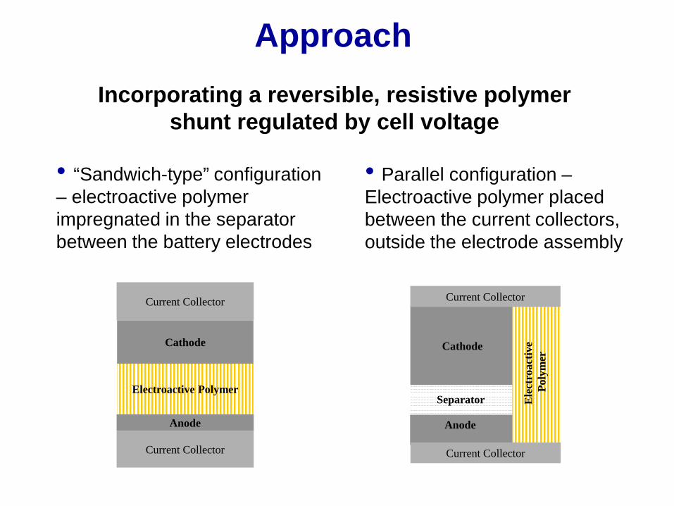
• “Sandwich-type” configuration – electroactive polymer impregnated in the separator between the battery electrodes
• Parallel configuration –Electroactive polymer placed between the current collectors, outside the electrode assembly
Approach
Anode
Cathode
Current Collector
Current Collector
Electroactive Polymer
Anode
Cathode
Current Collector
Separator
Current CollectorCurrent Collector
Ele
ctro
activ
ePo
lym
er
Incorporating a reversible, resistive polymer shunt regulated by cell voltage

Advantages of Our Approach• Advantages over external methods (such as integrated control circuits)
- Inexpensive as only a small amount of polymer needed- Minimum weight and volume - Self-actuated internally for cell balancing
• Advantages over internal methods (such as redox shuttles)- Good rate capability- No interference with the cell chemistry- No solubility and volatility issues - Versatile as cell holding potential is varied by the choice of polymer, polymer morphology and distribution, system configuration - Capable of low temperature protection, no diffusion limitation

Reversible redox couple SOC dependent conductivity
Electroactive Polymers
-10
-8
-6
-4
-2
0
3
3.2
3.4
3.6
3.8
4
4.2
4.4
0 0.05 0.1 0.15 0.2 0.25 0.3 0.35State of Charge
Open C
ircuit Voltage (V)
log
(con
duct
ivity
/Scm
-1)
Neutral polymer: 10-9
Oxidized polymer: 0.1Poly (3-butylthiophene)
(P3BT)
• Unique properties of electroactive polymers make them suitable for overcharge protection.

P3BT film
Pt
(+)(-)Li
• Polymer is capable of carrying a large amount of current.
Overcharge Protection Mechanism
• At positive electrode, polymer is not fully oxidized but highly conductive.• At negative electrode, polymer remains in neutral state, where most of the potential drop occurs.
incr
easi
ng o
xida
tion

• Highly reversible redox couple situated above the end-of-charge voltage of 4 V class cathodes
• Rapid change in electronic conductivity during the redox process to establish a steady state potential and create negligible self-discharge
• High conductivity at oxidized state for high rate capability (2C and above)
• Compatible with cell chemistry, no side reactions
• Stable under aging and cycling conditions for long battery life (15 year life, 300,000 Cycles)
• Low cost
Polymer Requirements for PHEV Protection

Redox Potential and Stability
Poly(9,9-dioctylfluorene) (PFO)
n
• Onset oxidation voltage is 4.1 V.• Good reversibility at high voltage.

Redox Potential and StabilityPoly[(9,9-dioctylfluorenyl-2,7-
diyl)-co-(1,4-phenylene)] (PFOP)
• Onset oxidation voltage is 4.25 V.• Slightly improved stability at low voltage.
2.5 3.0 3.5 4.0 4.5
Voltage (V)
Curre
nt (m
A)
1.5
1.0
-0.5
0.0
0.5
0.0 0.5 1.0 1.5 2.0 2.5 3.0
Voltage (V)
Curre
nt (m
A)
0.1
-0.3
-0.1
0.2
-0.2
0.0
5 mV/s, 30 cycles
Cycle number

Morphology and Rate Capability
• Polymer impregnated into the separator by solution casting. • Simple process but non-uniform distribution and poor utilization of the polymer.
Celgard 2500 PFOP/Celgard 2500

P3BT
• Aligned nanorods extend the full thickness of the AAO template prepared by electrochemical deposition.• Each polymer nanorod is capable of providing a direct, high-current path between the electrodes.
PFO
Morphology and Rate Capability

• Polymer fibers prepared on Al substrate by electrospinning.• Aspect ratio of the fibers are easily adjusted by synthesis conditions.• Process is easy to scale up.
Morphology and Rate Capability

• Polymer nanotubes electrochemically deposited in AAO template.• Pore size and length of the nanotubes tunable.
Morphology and Rate Capability

• Rate capability improved with new polymer morphologies.• Highest sustainable current density achieved in the nanotube composite. • Ten times improvement compared to the previous morphology.
Morphology and Rate Capability
LiPolymer composite
+ -
0.0 1.0 2.0 3.0 4.0 5.03.3
3.6
3.9
4.2
4.5
4.8
Cell h
oldi
ng v
olta
ge(V
)
Current density (mA/cm2)
Solution cast Celgard composite Nanofilber/AAO composite Nanotube/AAO composite
0 5 10 15 20 25 302.0
3.0
4.0
5.0
6.0
7.0
0.50.20.1Volta
ge (V
)
Time (min)
5
12
0.8
10 mA/cm2
Nanotube/AAO composite

10% P3BT 20% P3BT
40% P3BT 30% P3BT • P3BT/P(VDF-HFP) composite membranes prepared by solution casting.• Polymer ratio has minimal impact on separator morphology.• Need to increase density for use as separators.
Polymer Composite Membranes

0.0 1.0 2.0 3.0 4.0 5.03.6
3.9
4.2
4.5
4.8
5.1
5.4
5.7
20% 30% 40% 50%
Cell h
oldi
ng v
olta
ge(V
)
Current density (mA/cm2)
• Best rate capability achieved with 40% of electroactive polymer.• Further optimization is planned. • The process will be applied to make composite membranes incorporating fibers and nanotubes of the electroactive polymers.
Polymer Composite Membranes
5 10 15 20 25 302.0
3.0
4.0
5.0
6.0
7.0
8.0
Volta
ge (V
)
Time (min)
3
5 mA/cm2
20.1 0.2 0.5 0.8 1
40% P3BT

0 2 4 6 8 1040
60
80
100
120
140
160
180
Spec
ific c
apac
ity (m
Ah/g
)
Cycle number
Charge Disharge
Overcharge Protection – Spinel
• Overcharge protection with single electroactive polymer.• C/4 rate, 20% overcharged at a holding voltage of 4.3 V.• Long term stability is under further evaluation.
Li
Li1.05Mn1.95O4
Current Collector
Current Collector
PFOP/Celgard
0 10 20 30 40 50 60 702.5
3.0
3.5
4.0
4.5
5.0
Volta
ge (V
)
Time (h)
“Swagelok-type” Cell

0 20 40 60 80 100 120 1402.5
3.0
3.5
4.0
4.5
5.0
0.13 mA/cm2
0.26 mA/cm2
0.51 mA/cm2
1.0 mA/cm2
Volta
ge (V
)
Specific capacity (mAh/g)
Overcharge Protection – Spinel
• Slightly higher discharge capacity in the protected cell. • No self-discharge observed.• Rate capability up to 1 mA/cm2 (2C).
0 20 40 60 80 100 120 1402.5
3.0
3.5
4.0
4.5
5.0
Volta
ge (V
)
Specific capacity (mAh/g)
0.13 mA/cm2
0.26 mA/cm2
0.51 mA/cm2
1.0 mA/cm2

10 20 30 40 50 60 70 802.0
2.5
3.0
3.5
4.0
4.5
5.0
5.5
6.0
Volta
ge (V
)
Time (h)
0 10 20 30 40 50 60 702.0
2.5
3.0
3.5
4.0
4.5
5.0
5.5
6.0
Volta
ge (V
)
Time (h)
Overcharge Protection – Gen 2
Li
LiNi0.8Co0.15Al0.05O2
Current Collector
Current Collector
PFOP/Celgard
• C/12 rate, 20% overcharged at a holding voltage of 4.4 V.
“Swagelok-type” Cell

50 60 70 80 90 1002.0
2.5
3.0
3.5
4.0
4.5
5.0
Volta
ge (V
)
Time (h)
110 120 130 140 150 160 1702.0
2.5
3.0
3.5
4.0
4.5
5.0
Volta
ge (V
)
Time (h)
Overcharge Protection – Pouch CellPouch Cell
“sandwich-type” configuration
• C/7 rate, 20% overcharged at a holding voltage of 4.6 V.• Initial test showed overcharge protection for over ten cycles.
Li
Li1.05Mn1.95O4
Current Collector
Current Collector
PFOP/Celgard3 cm
4 cm

10 20 30 40 502.0
2.5
3.0
3.5
4.0
4.5
5.0
5.5
6.0
Volta
ge (V
)
Time (h)
Overcharge Protection – Pouch Cell
• Area ratio between the polymer and the electrode is 40:60.• C/6 rate, 20% overcharged at a holding voltage of 4.4 V.• Lower internal resistance in the parallel configuration.
Li
Li1.05Mn1.95O4
Current Collector
Current CollectorCurrent Collector
PFOP/CelgardCelgard
0 2 4 6 8 10 12 14 162.8
3.2
3.6
4.0
4.4
4.8
"Sandwich-type" Parallel
Volta
ge (V
)
Time (h)
Pouch Cell parallel configuration

Collaborations
• Robert Kostechi (LBNL) – Raman and FTIR Spectroscopy
• John Kerr (LBNL) – TGA and DSC
• Vince Battaglia, Marca Doeff (LBNL) – Electrode fabrication
• Gao Liu (LBNL) – Polymer synthesis
• Yueguang Zhang (Molecular Foundry) - Electrospining

Future Work
• Prepare composite separators with electroactive polymer fibers and nanotubes, and evaluate their rate capability and cycle life.
• Investigate other high-voltage electroactive polymers that may be suitable for overcharge protection for PHEV batteries. Optimize their morphology for maximum protection.
• Explore other cell configurations that may lead to improved protection and lowered cost.
• Investigate practical issues in “scaling-up” the concept.

Summary• A high-voltage polymer was found to have improved
stability at low voltage. It provided overcharge protection for various battery chemistries.
• Polymer nanotubes were found to carry higher current densities compared to other morphologies.
• Ways to cast composite separators incorporating electroactive polymer were explored.
• Overcharge protection was achieved in pouch cells in both “sandwich-type” and parallel configurations. The latter was found to have lowered holding potential due to reduced internal resistance.

Technical Back-Up Slide

Poly(3-butylthiophene)(P3BT, Vonset = 3.2 V)
S n
Poly(3-phenylthiophene) (P3PT, Vonset = 3.9 V)
S nS n
O
MeOn
Poly[2-methoxy-5-(2’-ethylhexyloxy)-1,4-phenylenevinylene]
(MEH-PPV, Vonset = 3.6 V)
Poly(9,9-dioctylfluorene) (PFO, Vonset = 4.1 V)
n
Polydiphenylamine(PDP, Vonset = 3.7 V)
HN
n
Polytriphenylamine(PTPAn, Vonset = 3.8 V)
N
n
Poly(4-bromo triphenylamine)
(PBTPAn, Vonset = 3.7 V)
N
n
Br
Oxidation Potentials of Studied Polymers
Poly[(9,9-dioctylfluorenyl-2,7-diyl)-co-(1,4-phenylene)]
(PFOP, Vonset= 4.25 V)
Top Related