


Languages
Pages
Legal


OPTISONIC 3400OPTISONIC 3400OPTISONIC 3400OPTISONIC 3400 Technical DatasheetTechnical DatasheetTechnical DatasheetTechnical Datasheet
Multi purpose, all-round, ultrasonic flowmeter for liquids
• Measurement of (non-) conductive, low and high viscous liquids, from -200° C to +250°C media temperature
• Accurate bi-directional measurement that starts from zero flow• Advanced signal converter, covering all I/O 's and communication protocols
© KROHNE 11/2013 - 4002037602 TD OPTISONIC 3400 R02 en

CONTENTS
2 www.krohne.com 11/2013 - 4002037602 TD OPTISONIC 3400 R02 en
OPTISONIC 3400
1 Product features 4
1.1 Multipurpose, all round ultrasonic flow meter in all process industries ....................... 41.2 Variants............................................................................................................................. 61.3 Features on request ......................................................................................................... 71.4 Measuring principle.......................................................................................................... 8
2 Technical data 9
2.1 Technical data................................................................................................................... 92.2 Dimensions and weights ................................................................................................ 21
2.2.1 Variants ................................................................................................................................. 212.2.2 Standard flow sensor DN300 and smaller ........................................................................... 222.2.3 Standard flow sensor DN350 and larger.............................................................................. 262.2.4 Flow sensor variant DN350 and larger................................................................................ 282.2.5 Signal converter housing ...................................................................................................... 29
3 Installation 30
3.1 Intended use ................................................................................................................... 303.2 General notes on installation ......................................................................................... 303.3 Vibration.......................................................................................................................... 303.4 Installation requirements signal converter ................................................................... 303.5 Installation conditions .................................................................................................... 31
3.5.1 Inlet and outlet ...................................................................................................................... 313.5.2 Bends in 2 or 3 dimensions................................................................................................... 313.5.3 T-section ............................................................................................................................... 313.5.4 Bends .................................................................................................................................... 323.5.5 Open feed or discharge......................................................................................................... 323.5.6 Position of pump ................................................................................................................... 333.5.7 Control valve ......................................................................................................................... 333.5.8 Down going pipeline over 5 m /16 ft length.......................................................................... 343.5.9 Insulation............................................................................................................................... 343.5.10 Mounting ............................................................................................................................. 353.5.11 Flange deviation .................................................................................................................. 353.5.12 Mounting position................................................................................................................ 35
4 Electrical connections 36
4.1 Safety instructions.......................................................................................................... 364.2 Signal cable (remote versions only)............................................................................... 364.3 Power supply .................................................................................................................. 374.4 Inputs and outputs, overview ......................................................................................... 38
4.4.1 Combinations of the inputs/outputs (I/Os) ........................................................................... 384.4.2 Description of the CG number .............................................................................................. 394.4.3 Fixed, non-alterable input/output versions.......................................................................... 404.4.4 Alterable input/output versions............................................................................................ 41
5 Applications 42

CONTENTS
3www.krohne.com11/2013 - 4002037602 TD OPTISONIC 3400 R02 en
OPTISONIC 3400
5.1 Device Configuration Form ............................................................................................ 42
6 Notes 44

1 PRODUCT FEATURES
4
OPTISONIC 3400
www.krohne.com 11/2013 - 4002037602 TD OPTISONIC 3400 R02 en
1.1 Multipurpose, all round ultrasonic flow meter in all process industries
The OPTISONIC 3400 OPTISONIC 3400 OPTISONIC 3400 OPTISONIC 3400 flowmeter is an unique, 3-beam, inline, ultrasonic flowmeter, designed especially for measuring homogeneous conductive and non-conductive liquids, with high accuracy and reproducibility, over a long period of time. KROHNE is a main supplier for ultrasonic in-line process flowmeters for liquids with the largest installed base / proven record in terms of robustness and measurement accuracy.
Building on vast knowledge and expertise, KROHNE now introduces the OPTISONIC 3400 OPTISONIC 3400 OPTISONIC 3400 OPTISONIC 3400 . This flowmeter is able to measure:
• conductive and non-conductive liquids• cryogenic - and high process temperatures• standard and straightforward applications and applications that require high performance• non-viscous aqueous liquids and extreme viscous liquids• low pressure ratings and extreme pressure ratings
The OPTISONIC 3400 OPTISONIC 3400 OPTISONIC 3400 OPTISONIC 3400 ...features advanced meter diagnostics. This provides extensive self-checking of internal circuits and information regarding the health of the measuring sensor, but just as importantly, vital information about the process and process conditions.
Fieldbusses are, HART®7, Foundation Fieldbus, Profibus PA and Modbus, all with NAMUR NE 107. These advanced diagnostic features makes process life comfortable, reliable and accurate over a long period of time.
The OPTISONIC 3400 OPTISONIC 3400 OPTISONIC 3400 OPTISONIC 3400 ...features velocity of soundAnother unique feature of the OPTISONIC 3400 is the free of charge measurement of velocity of sound per acoustic path. For instance, this can supply information about pollution in the liquid, or changes in the process conditions.
1 High performance signal converter for all applications2 Robust body without moving parts
PRODUCT FEATURES 1
5
OPTISONIC 3400
www.krohne.com11/2013 - 4002037602 TD OPTISONIC 3400 R02 en
Highlights• Advanced signal converter with full range of I/O 's and communication protocols• Diagnostic functions according to NAMUR NE107• Improved user interface: optical- and push buttons• Completely welded construction, wear and maintenance free• Full bore, unobstructed sensor tube, without pressure loss and without moving parts• Accurate bi-directional flow measurement, with three beams to measure continuously, and
starts measurement at nearly zero flow• Multipurpose, all round, ultrasonic flowmeter for single phase liquids
Industries• Chemicals• Petrochemicals• Oil & Gas• Energy• Water (utilities)
Applications• Conductive and non-conductive liquids• Cryogenic- and high process temperature, low and extreme high pressure range • Expanded applicability; for standard and high performance applications• Measuring aqueous liquids as well as extreme viscous oils• High turn down ratio; e.g. transportation pipeline measurements• Broad pressure and temperature range (e.g. midstream oil measurements)• Multiple products; e.g. allocation measurements in on/off loading• Water utilities in all process industries; make-up water, boiler feed water, demineralized
water

1 PRODUCT FEATURES
6
OPTISONIC 3400
www.krohne.com 11/2013 - 4002037602 TD OPTISONIC 3400 R02 en
1.2 Variants
An OPTISONIC 3400OPTISONIC 3400OPTISONIC 3400OPTISONIC 3400 flowmeter consists of an OPTISONIC 3000 flow sensor and an UFC 400 signal convertor. The standard version is available as a compact and remote version. Next to standard, also variants for demanding applications can be supplied.
OPTISONIC 3000OPTISONIC 3000OPTISONIC 3000OPTISONIC 3000
Flow sensor variants for demanding applicationsFlow sensor variants for demanding applicationsFlow sensor variants for demanding applicationsFlow sensor variants for demanding applications
A full range of flow sensors to cover simple to difficult applications, such as:
1. For extended process temperatures up to 250°C / 482°F (remote version)2. Cryogenic version: for extreme low process temperatures, as low as -200°C / [-328°F (remote
version, IP68)3. High viscous liquids: range from 100...1000 cSt4. High pressure rating
1 2 3 4 (e.g images )
• CompactCompactCompactCompact version up to 140°C / 284 °F• Aluminium or stainless steel housing
UFC 400UFC 400UFC 400UFC 400• Remote;
Aluminium or stainless steel housing
• RemoteRemoteRemoteRemote version up to 180°C / 356 °F
• Aluminium or stainless steel housing Ex and non-Ex IP66/IP67

PRODUCT FEATURES 1
7
OPTISONIC 3400
www.krohne.com11/2013 - 4002037602 TD OPTISONIC 3400 R02 en
1.3 Features on request
Including heating jacketIncluding heating jacketIncluding heating jacketIncluding heating jacket
• for steam or thermal oil tracing of the flowmeter• suitable for standard and variant for extended
process temperatures (remote)
Flangeless, weld-in connectionsFlangeless, weld-in connectionsFlangeless, weld-in connectionsFlangeless, weld-in connections
• greenfield• flexibility in innerpipe diameters

1 PRODUCT FEATURES
8
OPTISONIC 3400
www.krohne.com 11/2013 - 4002037602 TD OPTISONIC 3400 R02 en
1.4 Measuring principle
• Like canoes crossing a river, acoustic signals are transmitted and received along a diagonal measuring path.
• A sound wave going downstream with the flow travels faster than a sound wave going upstream against the flow.
• The difference in transit time is directly proportional to the mean flow velocity of the medium.
Figure 1-1: Measuring principle
1 Transducer A2 Transducer B3 Flow velocity4 Angle of incidence5 Velocity of sound of liquid6 Path length7 Inner diameter

TECHNICAL DATA 2
9
OPTISONIC 3400
www.krohne.com11/2013 - 4002037602 TD OPTISONIC 3400 R02 en
2.1 Technical data
• The following data is provided for general applications. If you require data that is more relevant to your specific application, please contact us or your local sales office.
• Additional information (certificates, special tools, software,...) and complete product documentation can be downloaded free of charge from the website (Download Center).
Measuring systemMeasuring principle Ultrasonic transit time
Application range Flow measurement of (non) conductive fluids
Measured valueMeasured valueMeasured valueMeasured value
Primary measured value Transit time
Secondary measured values Volume flow, mass flow, flow speed, flow direction, velocity of sound, gain, signal to noise ratio, reliability of flow measurement, totalised volume or mass
DesignFeatures 3 parallel acoustic path fully welded.
Modular construction The measurement system consists of a measuring sensor and a signal converter.
Compact version OPTISONIC 3400
Remote version OPTISONIC 3000 F with UFC 400 signal converter
Nominal diameter DN25...3000 / 1...120"
Measurement range 0.3...20 m/s / 0.98...65 ft/s
Signal converterSignal converterSignal converterSignal converter
Inputs / outputs Current (incl. HART®), pulse, frequency and/or status output, limit switch and/or control input (depending on the I/O version)
Totaliser 2 (optional 3) internal totalisers with a max. of 8 digits (e.g. for totalising volume and/or mass units)
Verification and self-diagnostics Integrated verification, diagnostic functions: measuring device, process, measured values, device configuration, etc.
Communication interfaces Modbus RS485, HART® 7, Foundation Fieldbus ITK6, Profibus PA Profile 3.02

2 TECHNICAL DATA
10
OPTISONIC 3400
www.krohne.com 11/2013 - 4002037602 TD OPTISONIC 3400 R02 en
Display and user interfaceDisplay and user interfaceDisplay and user interfaceDisplay and user interface
Graphic display LC display, backlit white
Size: 128x64 pixels, corresponds to 59x31 mm = 2.32"x1.22"
Display turnable in 90° steps.
Operating elements 4 optical and push buttons for operator control of the signal converter without opening the housing.
Option: Infrared interface (GDC)
Remote operation PACTwareTM including Device Type Manager (DTM)
HART® handheld communicator (Emerson), AMS (Emerson), PDM (Siemens)
All DTM's and drivers will be available at the internet homepage of the manufacturer.
Display functionsDisplay functionsDisplay functionsDisplay functions
Operating menu Programming of parameters at 2 measured value pages, 1 status page, 1 graphic page (measured values and descriptions adjustable as required)
Language of display texts English, French, German
Measurement functions Units:Units:Units:Units: Metric, British and US units selectable as desired from lists for volume/mass flow and counting, velocity, temperature.
Measured values:Measured values:Measured values:Measured values: volume flow, mass flow, flow speed, velocity of sound, gain, signal to noise ratio, flow direction, diagnostics
Diagnostic functions Standards:Standards:Standards:Standards: VDI/NAMUR NE 107
Status messages:Status messages:Status messages:Status messages: Output of status messages via display, current and/or status output, HART® or via other bus interface
Sensor diagnostics:Sensor diagnostics:Sensor diagnostics:Sensor diagnostics: per acoustic path velocity of sound, flow speed, gain, signal to noise ratio
Process diagnostics:Process diagnostics:Process diagnostics:Process diagnostics: empty pipe, signal integrity, cabling, flow conditions
Signal converter diagnostics:Signal converter diagnostics:Signal converter diagnostics:Signal converter diagnostics: data bus monitoring, I/O connections, electronics temperature, parameter and data integrity
Measuring accuracyReference conditions Reference conditions Reference conditions Reference conditions
Medium Water
Temperature 20°C / 68°F
Pressure 1 bar / 14.5 psi
Inlet section 10 DN
Maximum measuring errorMaximum measuring errorMaximum measuring errorMaximum measuring error
Standard: ±0.3% ±2 mm/s of actual measured flow rate
Repeatability ±0.2%

TECHNICAL DATA 2
11
OPTISONIC 3400
www.krohne.com11/2013 - 4002037602 TD OPTISONIC 3400 R02 en
Operating conditionsTemperatureTemperatureTemperatureTemperature
Process temperature Compact version:Compact version:Compact version:Compact version: -45...+140°C / -49...+284°F(for stainless steel housing at ambient temperature ≤ 45°C / +113°F)
Remote version:Remote version:Remote version:Remote version: -45...+180°C / -49...+356°F
Extended temperature version:Extended temperature version:Extended temperature version:Extended temperature version: -45...+250°C / -49...+482°F (only remote version)
Cryogenic version:Cryogenic version:Cryogenic version:Cryogenic version: -200...+180°C / -328...+356°F (only remote version, IP68, complete stainless steel)
Carbon steel flanges; minimal process temperatures acc. to EN1092: -10°C / +14°F; ASME: -29°C / -20°F
Ambient temperature Depending on the version and combination of outputs
-40…+65°C / -40…+149°F
Option (stainless steel converter housing): -40...+60°C / -40...+140°F
Ambient temperatures below -25°C / -13°F may affect the readability of the display.
Protect inside electronics against self-heating (increasing of the electronics temperature will lead to a reduction of the corresponding service life by a factor 2 for each step of 10°C / 50°F increase). Protect the signal converter from external heat sources such as direct sunlight, as higher temperatures reduce the life cycle of all electronic components.
Storage temperature -50…+70°C / -58…+158°F
PressurePressurePressurePressure
Atmospheric
EN 1092-1 DN25…50: PN 40
DN100…150: PN 16
DN200…1000: PN 10
DN1200…2000: PN 6
DN2200...3000: PN 2.5
Higher pressure ratings on request
ASME B16.5 1…24": 150 lb RF
1…24": 300 lb RF
1…24": 600 lb RF
1...24": 900 lb RF
Larger diameters on request.
JIS DN25...40: 20K
DN50...300: 10K
Properties of mediumProperties of mediumProperties of mediumProperties of medium
Physical condition Liquid, single phase (well mixed, rather clean)
Permissible gas content ≤ 2% (volume)
Permissible solid content ≤ 5% (volume)
Viscosity Standard:Standard:Standard:Standard: Up to 100 cSt (for all diameters)
Option:Option:Option:Option: High viscosity variant up to 1000 cSt

2 TECHNICAL DATA
12
OPTISONIC 3400
www.krohne.com 11/2013 - 4002037602 TD OPTISONIC 3400 R02 en
Installation conditionsInstallation conditionsInstallation conditionsInstallation conditionsInstallation For detailed information refer to Installation on page 30.
Inlet run Minimal 5 DN (straight inlet)
If no details are known, minimal 10 DN recommended
Outlet run Minimal 3 DN (straight outlet)
If no details are known, minimal 5 DN recommended
Dimensions and weights For detailed information refer to Dimensions and weights on page 21.
MaterialsMaterialsMaterialsMaterialsMeasuring sensorMeasuring sensorMeasuring sensorMeasuring sensor
Flanges (wetted)
DN25...65 / 1"...2.5 ": Stainless steel 1.4404 (AISI 316L)
DN80...3000 / 3"...120": Carbon steel
Other materials on request.
Measuring Tube (wetted)
DN25...300 / 1"...12": Stainless steel 1.4404 (AISI 316L), some 316Ti / 1.4571
DN350..3000 / 14"...120": Carbon steel
Other materials on request.
Measuring sensor housing DN25...65 / 1"...2.5": Stainless steel 1.4404 (AISI 316L)
DN80...3000 / 3"...120": Carbon steel
Transducer
Transducers (wetted) Stainless steel 1.4404 (AISI 316L)
Other materials on request.
Transducer holdersincl. caps
DN350...3000 / 14"...120"; Stainless steel 1.4404 (AISI 316L) (same material as flanges)
Tube transducer cabling Stainless steel 1.4404 (AISI 316L)
Connection box and connection box support(remote version only)
Standard: Die-cast aluminium; polyurethane coated
Option: Stainless steel 316 (1.4408)
Coating (measuring sensor) Standard: Polyurethane
Option: Offshore coating
NACE conformity On request; wetted materials conform NACE MR 175/103
Signal converterSignal converterSignal converterSignal converter
Housing Versions C and F: Die-cast aluminium
Option: Stainless steel 316 (1.4408)
Coating Standard: Polyurethane
Option: Offshore coating

TECHNICAL DATA 2
13
OPTISONIC 3400
www.krohne.com11/2013 - 4002037602 TD OPTISONIC 3400 R02 en
Electrical connectionsElectrical connectionsElectrical connectionsElectrical connectionsDescription of used abbreviations; Q=xxx; Imax = maximum current; Uin = xxx; Uint = internal voltage; Uext = external voltage; Uint, max = maximal internal voltage
General Electrical connection is carried out in conformity with the VDE 0100 directive "Regulations for electrical power installations with line voltages up to 1000 V" or equivalent national specifications.
Power supply Standard: 100…230 VAC (-15% / +10%), 50/60 Hz
Option: 24 VAC/DC (AC: -15% / +10%; DC: -25% / +30%)
Power consumption AC: 22 VA
DC: 12 W
Signal cable (remote version only)
MR06 (shielded cable with 6 coax cores): Ø 10.6 mm / 0.4"
5 m / 16 ft
Option: 10...30 m / 33...98 ft
Cable entries Standard: M20 x 1.5 (8...12 mm)
Option: ½" NPT, PF ½
Inputs and outputsGeneral All outputs are electrically isolated from each other and
from all other circuits.
All operating data and output values can be adjusted.
Description of used abbreviations Uext = external voltage; RL = load + resistance; U0 = terminal voltage; Inom = nominal currentSafety limit values (Ex i):Ui = max. input voltage; Ii = max. input current; Pi = max. input power rating;Ci = max. input capacity; Li = max. input inductivity

2 TECHNICAL DATA
14
OPTISONIC 3400
www.krohne.com 11/2013 - 4002037602 TD OPTISONIC 3400 R02 en
Current outputCurrent outputCurrent outputCurrent output
Output data Measurement of volume flow, mass flow, flow speed, velocity of sound, gain, SNR, diagnostics 1, 2, NAMUR NE107, HART® communication.
Temperature coefficient Typically ±30 ppm/K
Settings Without HARTWithout HARTWithout HARTWithout HART®
Q = 0%: 0…20 mA; Q = 100%: 10…20 mA
Error identification: 3…22 mA
With HARTWith HARTWith HARTWith HART®
Q = 0%: 4…20 mA; Q = 100%: 10…20 mA
Error identification: 3…22 mA
Q = 100%: 10…20 mA
Error identification: 3…22 mA
Operating data Basic I/OsBasic I/OsBasic I/OsBasic I/Os Modular I/OsModular I/OsModular I/OsModular I/Os Ex iEx iEx iEx i
Active Uint, nom = 24 VDC
I ≤ 22 mA
RL ≤ 1 kΩ
Uint, nom = 20 VDC
I ≤ 22 mA
RL ≤ 450 Ω
U0 = 21 VI0 = 90 mAP0 = 0.5 WC0 = 90 nF / L0 = 2 mHC0 = 110 nF / L0 = 0.5 mH
Passive Uext ≤ 32 VDC
I ≤ 22 mA
U0 ≥ 1.8 V
RL, max = (Uext - U0 / Imax
Uext ≤ 32 VDC
I ≤ 22 mA
U0 ≥ 4 V
RL, max = (Uext - U0 / Imax
Ui = 30 VIi = 100 mAPi = 1 WCi = 10 nFLi ~ 0 mH

TECHNICAL DATA 2
15
OPTISONIC 3400
www.krohne.com11/2013 - 4002037602 TD OPTISONIC 3400 R02 en
HARTHARTHARTHART®
Description HART® protocol via active and passive current output
HART® version: V7
Universal HART® parameter: completely integrated
Load ≥ 250 Ω t HART® test point:Note maximum load for current output!
Multidrop Yes, current output = 4 mA
Multidrop addresses adjustable in operation menu 1...15
Device drivers DD for FC 375/475, AMS, PDM, DTM for FDT
Pulse or frequency outputPulse or frequency outputPulse or frequency outputPulse or frequency output
Output data Volume flow, mass flow
Function Adjustable as pulse of frequency output
Pulse rate/frequency 0.01...10000 pulses/s or Hz
Settings For Q = 100%: 0.01... 10000 pulses per second or pulses per unit volume.
Pulse width: adjustable as automatic, symmetric or fixed (0.05...2000 ms)
Operating data Basic I/Os Modular I/Os Ex i
Active - Unom = 24 VDC -
fmax in operating menu set to: ffffmaxmaxmaxmax ≤ 100 Hz: 100 Hz: 100 Hz: 100 Hz:
I ≤ 20 mA
RL, max = 47 kΩ
open:I ≤ 0.05 mA closed: U0,nom = 24 V at I = 20 mA
Fmax in operating menu set to: 100 Hz < f100 Hz < f100 Hz < f100 Hz < fmaxmaxmaxmax ≤ 10 10 10 10 kHz:kHz:kHz:kHz:
I ≤ 20 mA
RL ≤ 10 kΩ for f ≤ 1 kHzRL ≤ 1 kΩ for f ≤ 10 kHz
open: I ≤ 0.05 mA closed: U0,nom = 22.5 V at I = 1 mA U0,nom = 21.5 V at I = 10 mA U0,nom = 19 V at I = 20 mA

2 TECHNICAL DATA
16
OPTISONIC 3400
www.krohne.com 11/2013 - 4002037602 TD OPTISONIC 3400 R02 en
Passive Uext ≤ 32 VDC -
fmax in operating menu set to: ffffmaxmaxmaxmax ≤ 100 Hz: 100 Hz: 100 Hz: 100 Hz:
I ≤ 100 mA
RL, max = 47 kΩRL, max = (Uext - U0) / Imax
open: I ≤ 0.05 mA at Uext = 32 VDC closed: U0, max = 0.2 V at I ≤ 10 mA U0, max = 2 V at I ≤ 100 mA
fmax in operating menu set to:100 Hz < f100 Hz < f100 Hz < f100 Hz < fmaxmaxmaxmax ≤ 10 kHz: 10 kHz: 10 kHz: 10 kHz:
I ≤ 20 mA
RL ≤ 10 kΩ for f ≤ 1 kHzRL ≤ 1 kΩ for f ≤ 10 kHzRL, max = (Uext - U0) / Imax
open: I ≤ 0.05 mA at Uext = 32 VDC closed: U0, max = 1.5 V at I ≤ 1mA U0, max = 2.5 V at I ≤ 10 mA U0, max = 5.0 V at I ≤ 20 mA
NAMUR - Passive to EN 60947-5-6
open: Inom = 0.6 mA closed: Inom = 3.8 mA
Passive to EN 60947-5-6
open: Inom = 0.43 mA closed: Inom = 4.5 mA
Ui = 30 V Ii = 100 mA Pi = 1 W Ci = 10 nF Li = 0 mH

TECHNICAL DATA 2
17
OPTISONIC 3400
www.krohne.com11/2013 - 4002037602 TD OPTISONIC 3400 R02 en
Status output / limit switchStatus output / limit switchStatus output / limit switchStatus output / limit switch
Function and settings Adjustable as automatic measuring range conversion, display of flow direction, overflow, error, switching point
Valve control with activated dosing function
Operating data Basic I/Os Modular I/Os Ex i
Active - Uint = 24 VDC
I ≤ 20 mA
RL, max = 47 kΩ
open: I ≤ 0.05 mA closed: U0, nom = 24 V at I = 20 mA
-
Passive Uext ≤ 32 VDC
I ≤ 100 mA
RL, max = 47 kΩ RL, max = (Uext - U0) / Imax
open: I ≤ 0.05 mA at Uext = 32 VDC closed: U0, max = 0.2 V at I ≤ 10 mA U0, max = 2 V at I ≤ 100 mA
Uext = 32 VDC
I ≤ 100 mA
RL, max = 47 kΩ RL, max = (Uext - U0) / Imax
open: I ≤ 0.05 mA at Uext = 32 VDC closed: U0, max = 0.2 V at I ≤ 10 mA U0, max = 2 V at I ≤ 100 mA
-
NAMUR - Passive to EN 60947-5-6
open: Inom = 0.6 mA closed: Inom = 3.8 mA
Passive to EN 60947-5-6
open: Inom = 0.43 mA closed: Inom = 4.5 mA
Ui = 30 V Ii = 100 mA Pi = 1 W Ci = 10 nF Li = 0 mH

2 TECHNICAL DATA
18
OPTISONIC 3400
www.krohne.com 11/2013 - 4002037602 TD OPTISONIC 3400 R02 en
Control inputControl inputControl inputControl input
Function Hold value of the outputs (e.g. for cleaning work), set value of the outputs to "zero", counter and error reset, stop counter, range conversion, zero calibration
Start of dosing when dosing function is activated.
Operating data Basic I/Os Modular I/Os Ex i
Active - Uint = 24 VDC
Terminals open: U0, nom = 22 V
Terminals bridged: Inom = 4 mA
On: U0 ≥ 12 V with Inom = 1.9 mA
Off: U0 ≤ 10 V with Inom = 1.9 mA
-
Passive Uext ≤ 32 VDC
Imax = 6.5 mA at Uext ≤ 24 VDC
Imax = 8.2 mA at Uext ≤ 32 VDC
Contact closed (On): U0 ≥ 8 V with Inom = 2.8 mA
Contact open (Off): U0 ≤ 2.5 V with Inom = 0.4 mA
Uext ≤ 32 VDC
Imax = 9.5 mA at Uext ≤ 24 V
Imax = 9.5 mA at Uext ≤ 32 V
Contact closed (On): U0 ≥ 3 V with Inom = 1.9 mA
Contact open (Off): U0 ≤ 2.5 V with Inom = 1.9 mA
Uext ≤ 32 VDC
I ≤ 6 mA at Uext = 24 V I ≤ 6.6 mA at Uext = 32 V
On: U0 ≥ 5.5 V or I ≥ 4mA Off: U0 ≤ 3.5 V or I ≤ 0.5 mA
Ui = 30 V Ii = 100 mA Pi = 1 W Ci = 10 nF Li = 0 mH
NAMUR - Active to EN 60947-5-6
Contact open: U0, nom = 8.7 V
Contact closed (On): Inom = 7.8 mA
Contact open (off): U0, nom = 6.3 V with Inom = 1.9 mA
Identification for open terminals: U0 ≥ 8.1 V with I ≤ 0.1 mA
Identification for short circuited terminals: U0 ≤ 1.2 V with I ≥ 6.7 mA
-

TECHNICAL DATA 2
19
OPTISONIC 3400
www.krohne.com11/2013 - 4002037602 TD OPTISONIC 3400 R02 en
PROFIBUS PAPROFIBUS PAPROFIBUS PAPROFIBUS PA
Description Galvanically isolated acc. to IEC 61158
Profile version: 3.02
Current consumption: 10.5 mA
Permissible bus voltage: 9...32 V; in Ex application 9...24 V
Bus interface with integrated reverse polarity protection
Typical error current FDE (Fault Disconnection Electronic): 4.3 mA
Bus address adjustable via local display on the measuring device
Function blocks 6 x analogue input, 3 x totaliser
Output data Volume flow, mass flow, velocity of sound, flow speed, gain, SNR, electronic temperature, power supply
(Further meas. values and diagnostic data is available via acyclic access)
FOUNDATION FieldbusFOUNDATION FieldbusFOUNDATION FieldbusFOUNDATION Fieldbus
Description Galvanically isolated acc. to IEC 61158
Current consumption: 10.5 mA
Permissible bus voltage: 9...32 V; in Ex application 9...24 V
Bus interface with integrated reverse polarity protection
Link Master function (LM) supported
Tested with Interoperable Test Kit (ITK) version 6.0
Function blocks 1 x analogue input, 2 x integrator, 1 x PID
Output data Volume flow, mass flow, flow speed, electronic temperature, velocity of sound, gain, SNR Diagnostic data
MODBUSMODBUSMODBUSMODBUS
Description Modbus RTU, Master / Slave, RS485
Address range 1…247
Supported function codes 01, 02, 03, 04, 05, 08, 16, 43
Supported Baudrate 1200, 2400, 4800, 9600, 19200, 38400, 57600, 115200 Baud

2 TECHNICAL DATA
20
OPTISONIC 3400
www.krohne.com 11/2013 - 4002037602 TD OPTISONIC 3400 R02 en
Approvals and certificatesCECECECE
This device fulfills the statutory requirements of the EC directives. The manufacturer certifies successful testing of the product by applying the CE mark.
Electromagnetic compatibility Directive: 2004/108/EC, NAMUR NE21/04
Harmonized standard: EN 61326-1 : 2006
Low voltage directive Directive: 2006/95/EC
Harmonized standard: EN 61010 : 2001
Pressure equipment directive Directive: 97/23/EC
Category I, II, III or SEP
Fluid group 1, table 6
Production module H
NAMUR NE 21,43,53,80,107
Other approvals and standardsOther approvals and standardsOther approvals and standardsOther approvals and standards
Non-Ex Standard
Hazardous areasHazardous areasHazardous areasHazardous areas
Ex zone 1 - 2 For detailed information, please refer to the relevant Ex documentation.
According to European Directive 94/4 EC (ATEX 100a)
IECEx Approval number; IECEx DEK13.0023 X
ATEX DEKRA 13ATEX0092X
cCSACSACSACSAus; class 1 Div. 1 and 2 Approval number; 2593926
NEPSI Approval number; [pending]
Protection category acc. to IEC 529 / EN 60529
Signal converterSignal converterSignal converterSignal converter
Compact (C): IP66/67 (NEMA 4X/6)
Field (F): IP66/67 (NEMA 4X/6)
All flow sensorsAll flow sensorsAll flow sensorsAll flow sensors
IP67 (NEMA 6)
Option: IP68 (NEMA 6P)
Shock resistance IEC 68-2-27
30 g for 18 ms
Vibration resistance IEC 68-2-6; 1g up to 2000 Hz
IEC 60721; 10g

TECHNICAL DATA 2
21
OPTISONIC 3400
www.krohne.com11/2013 - 4002037602 TD OPTISONIC 3400 R02 en
2.2 Dimensions and weights
2.2.1 Variants
For all dimensions and options; see tables on next pages (tables not final)
Note; the cCSAus versions ( DN25...65 / 1...2.5") are manufactured with a heavy duty neck (SS) which is 3.6 mm / 0.14 inch higher.
Remote versionRemote versionRemote versionRemote version a = 88 mm / 3.5"
b = 139 mm / 5.5" 1
c = 106 mm / 4.2"
Total height = H + a 2
Compact versionCompact versionCompact versionCompact version a = 155 mm / 6.1"
b = 230 mm / 9.1" 1
c = 260 mm / 10.2"
Total height = H + a 2
1 The value may vary depending on the used cable glands.2 The value depends on version
Standard version and Standard version and Standard version and Standard version and Extended temperature - Extended temperature - Extended temperature - Extended temperature - High Viscosity - High Viscosity - High Viscosity - High Viscosity - Cryogenic versions;Cryogenic versions;Cryogenic versions;Cryogenic versions; ≤ DN300 / 12" DN300 / 12" DN300 / 12" DN300 / 12"
DIN: L= 250...500 mm / 9.8"...19.7"
ANSI: L= 250...500 mm / 9.8"...19.7"
* for Cryo - HV - XXT versions;ANSI: L= 250...550 mm / 9.8"...21.7"
Standard version;Standard version;Standard version;Standard version; ≥ DN350 / 14" DN350 / 14" DN350 / 14" DN350 / 14"
DIN: L= 500..600 mm / 19.7"...23.6"
ANSI: L= 500...800 mm / 19.7"...31.5"
Extended temperature - Extended temperature - Extended temperature - Extended temperature - High Viscosity - High Viscosity - High Viscosity - High Viscosity - Cryogenic version; Cryogenic version; Cryogenic version; Cryogenic version; ≥ DN350 / 14" DN350 / 14" DN350 / 14" DN350 / 14"
DIN: L= 500...700 mm / 19.7"...27.6"
ANSI: L= 550...850 mm / 21.7"...33.5"
2 TECHNICAL DATA
22
OPTISONIC 3400
www.krohne.com 11/2013 - 4002037602 TD OPTISONIC 3400 R02 en
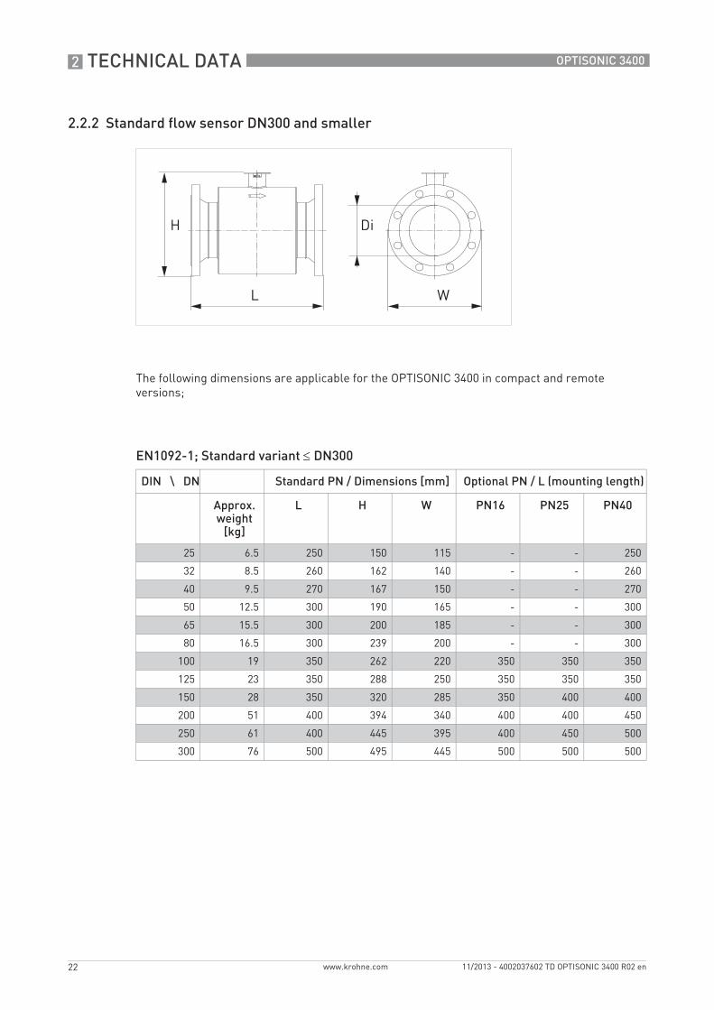
2.2.2 Standard flow sensor DN300 and smaller
The following dimensions are applicable for the OPTISONIC 3400 in compact and remote versions;
EN1092-1; Standard variant ≤ DN300
DIN \ DN Standard PN / Dimensions [mm] Optional PN / L (mounting length)
L H W PN16 PN25 PN40Approx. weight
[kg]
25 6.5 250 150 115 - - 250
32 8.5 260 162 140 - - 260
40 9.5 270 167 150 - - 270
50 12.5 300 190 165 - - 300
65 15.5 300 200 185 - - 300
80 16.5 300 239 200 - - 300
100 19 350 262 220 350 350 350
125 23 350 288 250 350 350 350
150 28 350 320 285 350 400 400
200 51 400 394 340 400 400 450
250 61 400 445 395 400 450 500
300 76 500 495 445 500 500 500

TECHNICAL DATA 2
23
OPTISONIC 3400
www.krohne.com11/2013 - 4002037602 TD OPTISONIC 3400 R02 en
ASME 150 lb
ASME 300 lb
Nominal size
Approx. weight Dimensions in mm and inch
L H W Di
[lb] [kg] [inch] [mm] [inch] [mm] [inch] [mm] [inch] [mm]
1 15 7 9.84 250 5.98 152 4.25 108 1.05 26.7
1¼ 19 9 10.24 260 6.14 156 4.65 118 1.38 35.1
1½ 21 10 10.63 270 6.34 161 5.0 127 1.61 40.9
2 27 12 11.81 300 7.36 187 5.98 152 2.07 52.5
2½ 31 15 11.81 300 8.54 217 7.01 178 2.47 62.7
3 41 19 13.78 350 9.25 235 7.48 190 3.07 77.9
4 54 24 13.78 350 10.47 266 9.02 229 4.03 102.3
5 65 29 13.78 350 11.42 290 10.0 254 5.05 128.2
6 84 38 15.75 400 12.48 317 10.98 279 6.07 154.1
8 146 66 15.75 400 15.71 399 14.41 366 7.98 202.7
10 167 76 19.69 500 18.03 458 16.54 420 10.04 255
12 236 107 19.69 500 20.55 522 19.02 483 12.01 305
Nominal size
Approx. weight Dimensions in mm and inch
L H W Di
[lb] [kg] [inch] [mm] [inch] [mm] [inch] [mm] [inch] [mm]
1 18 8 9.84 250 6.30 160 4.88 124 1.05 26.7
1¼ 20 9 10.24 260 6.46 164 5.24 133 1.38 35.1
1½ 24 11 10.63 270 6.89 175 6.10 155 1.61 40.9
2 33 15 11.81 300 7.60 193 6.50 165 2.07 52.5
2½ 42 19 11.81 300 8.11 206 7.48 190 2.47 62.7
3 51 23 13.78 350 9.61 244 8.27 210 3.07 77.9
4 77 35 15.75 400 10.98 279 10.0 254 4.03 102.3
5 97 44 15.75 400 11.93 303 10.98 279 5.05 128.2
6 126 57 17.72 450 13.31 338 12.60 320 6.07 154.1
8 205 93 17.72 450 16.46 418 15.00 381 7.98 202.7
10 287 130 19.69 500 18.78 477 17.48 444 10.04 255
12 399 181 23.62 600 21.3 541 20.51 521 12.01 305

2 TECHNICAL DATA
24
OPTISONIC 3400
www.krohne.com 11/2013 - 4002037602 TD OPTISONIC 3400 R02 en
ASME 600 lb
ASME 900 lb
Nominal size
Approx. weight Dimensions in mm and inch
L H W Di
[lb] [kg] [inch] [mm] [inch] [mm] [inch] [mm] [inch] [mm]
1 15 7 10.63 270 6.30 160 4.88 124 1.05 26.7
1½ 22 10 11.42 290 6.89 175 6.14 156 1.61 40.9
2 33 15 12.99 330 7.60 193 6.50 165 2.07 52.6
3 62 28 15.75 400 9.61 244 8.27 210 2.90 73.7
4 106 48 15.75 400 11.34 288 10.75 273 3.83 97.3
6 207 94 19.69 500 13.98 355 14.02 356 5.76 146.3
8 326 148 19.69 500 17.24 438 16.50 419 7.63 193.8
10 547 248 23.62 600 20.04 509 20.0 508 9.33 237.8
12 644 292 23.62 600 22.05 560 22.1 559 11.37 288.8
Nominal size
Approx. weight Dimensions in mm and inch
L H W Di
[lb] [kg] [inch] [mm] [inch] [mm] [inch] [mm] [inch] [mm]
3 95 43 17.72 450 10.24 260 9.49 241 2.62 66.6
4 146 66 17.72 450 11.73 298 11.50 292 3.44 87.3
6 304 138 23.62 600 14.49 368 15.00 381 5.19 131.7

TECHNICAL DATA 2
25
OPTISONIC 3400
www.krohne.com11/2013 - 4002037602 TD OPTISONIC 3400 R02 en
EN1092-1; Extended temperature, High Viscosity & Cryogenic variant ≤ DN300
ASME B16.5; Extended temperature, High Viscosity & Cryogenic variant ≤ 12".
DIN \ DN Standard PN / Dimensions [mm] Optional PN / L (mounting length)
L H W PN16 PN25 PN40Approx. weight
[kg]
25 6.5 250 150 115 - - 250
32 8.5 260 162 140 - - 260
40 9.5 270 167 150 - - 270
50 12.5 300 190 165 - - 300
65 15.5 300 200 185 - - 300
80 16.5 300 239 200 - - 300
100 19 350 262 220 350 350 350
125 23 350 288 250 350 350 350
150 28 350 320 285 350 400 400
200 47 450 394 340 450 - 500
250 63 500 445 395 500 - 550
300 72 500 495 445 500 - 550
ASME size Standard (PN 150 lb) / Dimensions [inch]
Optional PN / L (mounting length)
L H W 300 lb 600 lb 900 lbApprox. weight [lb]
1 14 9.84 5.98 4.25 9.84 10.63 11.42
1¼ 16 10.24 6.14 4.65 10.24 - 11.81
1½ 20 10.63 6.34 5.0 10.63 11.42 11.81
2 24 11.81 7.4 6.0 11.81 12.99 14.57
2½ 30 11.81 8.5 7.0 11.81 - 15.35
3 40 13.78 9.3 7.5 13.78 15.75 17.72
4 54 13.78 10.5 9.0 15.75 15.75 17.72
5 66 13.78 11.4 10.0 15.75 - 19.69
6 84 15.75 12.5 11.0 17.72 19.69 23.62
8 146 17.72 15.7 14.5 19.69 21.65 31.5
10 166 21.65 18.0 16.5 21.65 25.59 31.5
12 236 21.65 20.6 19.0 23.62 27.56 35.43

2 TECHNICAL DATA
26
OPTISONIC 3400
www.krohne.com 11/2013 - 4002037602 TD OPTISONIC 3400 R02 en
2.2.3 Standard flow sensor DN350 and larger
The following dimensions are applicable for the OPTISONIC 3400 in compact and remote versions;
EN1092-1; Standard variant ≥ DN350.
ASME 150 lb
DIN \ DN Standard PN / Dimensions [mm] Optional PN / L (mounting length)
L H W PN16 PN25 PN40Approx. weight
[kg]
350 69 500 540 505 500 500 600
400 90 600 595 565 600 600 700
450 97 600 646 615 600 600 800
500 118 600 697 670 600 700 800
600 151 600 802 780 700 800 800
Nominal size
Approx. weight Dimensions in mm and inch
L H W Di
[lb] [kg] [inch] [mm] [inch] [mm] [inch] [mm] [inch] [mm]
14 283 128 27.56 700 20.91 531 20.98 533 13.27 337
16 355 161 31.50 800 23.15 588 23.50 597 15.28 388
18 396 181 31.50 800 24.88 632 25.00 635 17.24 438
20 537 244 31.50 800 27.28 693 27.48 698 19.25 489
24 704 320 31.50 800 31.54 801 32.01 813 23.25 591

TECHNICAL DATA 2
27
OPTISONIC 3400
www.krohne.com11/2013 - 4002037602 TD OPTISONIC 3400 R02 en
ASME 300 lb
ASME 600 lb
Nominal size
Approx. weight Dimensions in mm and inch
L H W Di
[lb] [kg] [inch] [mm] [inch] [mm] [inch] [mm] [inch] [mm]
14 513 233 27.56 700 22.05 560 22.99 584 13.13 333
16 683 306 31.50 800 24.29 617 25.51 648 15.00 381
18 850 387 31.50 800 26.54 674 27.99 711 16.87 428
20 1009 456 31.50 800 28.78 731 30.51 775 18.81 478
24 1459 663 31.50 800 33.54 852 35.98 914 22.64 575
Nominal size
Approx. weight Dimensions in mm and inch
L H W Di
[lb] [kg] [inch] [mm] [inch] [mm] [inch] [mm] [inch] [mm]
14 803 365 27.56 700 22.4 569 23.74 603 12.13 308
16 1140 518 31.50 800 25.0 636 27.01 686 13.94 354
18 1303 592 31.50 800 27.17 690 29.25 743 16.12 409
20 1800 818 35.43 900 29.53 750 32.01 813 17.44 443
24 2355 1070 35.43 900 34.06 865 37.01 940 21.65 550

2 TECHNICAL DATA
28
OPTISONIC 3400
www.krohne.com 11/2013 - 4002037602 TD OPTISONIC 3400 R02 en
2.2.4 Flow sensor variant DN350 and larger
The following dimensions are applicable for; Extended temperature , High Viscosity and Cryogenic variants
EN1092-1; Extended Temperature, High Viscosity & Cryogenic variant ≥ DN350.
ASME B16.5; Extended temperature, High Viscosity & Cryogenic variant 14"...24"
DIN \ DN Standard PN / Dimensions [mm] Optional PN / L (mounting length)
L H W PN16 PN25 PN40Approx. weight
[kg]
350 88 500 540 505 - - -
400 109 600 595 565 - - -
450 125 600 646 615 - - -
500 146 650 697 670 - - -
600 189 700 802 780 - - -
ASME size Standard PN / Dimensions [inch] Optional PN / L (=mounting length)
L H W 300 lb 600 lb 900 lbApprox. weight [lb]
14 290 27.56 20.9 21.0 27.6 29.5 35.4
16 365 31.50 23.2 23.5 31.5 31.5 39.4
18 410 31.50 24.9 25.0 31.5 33.5 39.4
20 510 31.50 27.3 27.5 31.5 35.4 39.4
24 680 33.47 32.4 32.0 33.5 37.4 51.2

TECHNICAL DATA 2
29
OPTISONIC 3400
www.krohne.com11/2013 - 4002037602 TD OPTISONIC 3400 R02 en
2.2.5 Signal converter housing
Dimensions and weights in mm and kg
Dimensions and weights in inch and lb
1 Compact housing (C)2 Field housing (F)
Version Dimensions [mm] Weight [kg]
a b c d e g h
C 202 120 155 260 137 - - 4.2
F 202 120 155 - - 295.8 277 5.7
Version Dimensions [inch] Weight [lb]
a b c d e g h
C 7.75 4.75 6.10 10.20 5.40 - - 9.30
F 7.75 4.75 6.10 - - 11.60 10.90 12.60

3 INSTALLATION
30
OPTISONIC 3400
www.krohne.com 11/2013 - 4002037602 TD OPTISONIC 3400 R02 en
3.1 Intended use
The OPTISONIC 3400OPTISONIC 3400OPTISONIC 3400OPTISONIC 3400 is designed exclusively for measurements on conductive and / or non-conductive fluids, in closed completely filled pipeline circuits. Excess of contaminations (gas, particles, 2 phases) disturb the acoustic signal and thus must be avoided.
The overall functionality of the OPTISONIC 3400OPTISONIC 3400OPTISONIC 3400OPTISONIC 3400 flowmeter, is the continuous measurement of actual volume flow, mass flow, flow speed, velocity of sound, gain, SNR, totalized flow mass and diagnosis values.
3.2 General notes on installation
3.3 Vibration
3.4 Installation requirements signal converter
• Allow 10…20 cm / 3.9…7.9" of space at the sides and rear of the signal converter to permit free air circulation.
• Protect signal converter against direct solar radiation, install a sunshield if necessary.• Signal converters installed in switchgear cabinets require adequate cooling, e.g. by fan or
heat exchanger.• Do not expose the signal converter to intense vibration.
Responsibility for the use of the measuring devices with regard to suitability, intended use and corrosion resistance of the used materials against the measured fluid lies solely with the operator.
The manufacturer is not liable for any damage resulting from improper use or use for other than the intended purpose.
Inspect the cartons carefully for damages or signs of rough handling. Report damage to the carrier and to the local office of the manufacturer.
Do a check of the packing list to make sure that you have all the elements given in the order.
Look at the device nameplate to ensure that the device is delivered according to your order. Check for the correct supply voltage printed on the nameplate.
Figure 3-1: Avoid vibrations
In case of expected vibrations, please install a field version.

INSTALLATION 3
31
OPTISONIC 3400
www.krohne.com11/2013 - 4002037602 TD OPTISONIC 3400 R02 en
3.5 Installation conditions
3.5.1 Inlet and outlet
3.5.2 Bends in 2 or 3 dimensions
3.5.3 T-section
Figure 3-2: Recommended inlet and oulet
1 Refer to chapter "Bends in 2 or 3 dimensions"2 ≥ 3 DN
Figure 3-3: 2 and 3 dimensional bends, in front of flowmeter
1 Bends in 2 dimensions: ≥ 5 DN; bends in 3 dimensions: ≥ 10 DN
Figure 3-4: Distance behind a T-section
1 ≥ 5 DN

3 INSTALLATION
32
OPTISONIC 3400
www.krohne.com 11/2013 - 4002037602 TD OPTISONIC 3400 R02 en
3.5.4 Bends
3.5.5 Open feed or discharge
Install meter on a lowered section of the pipe to ensure a full pipe condition through the meter.
Figure 3-5: Installation in bending pipes
Figure 3-6: Installation in bending pipes
Figure 3-7: Open discharge

INSTALLATION 3
33
OPTISONIC 3400
www.krohne.com11/2013 - 4002037602 TD OPTISONIC 3400 R02 en
3.5.6 Position of pump
3.5.7 Control valve
Never install flowmeter at a pump suction side in order to avoid cavitation or flashing in the flowmeter.
Figure 3-8: Position of pump
1 ≥ 15 DN
Figure 3-9: Installation in front of a control valve
1 ≥ 20 DN

3 INSTALLATION
34
OPTISONIC 3400
www.krohne.com 11/2013 - 4002037602 TD OPTISONIC 3400 R02 en
3.5.8 Down going pipeline over 5 m /16 ft length
Install air vent downstream of the flowmeter to prevent vacuum. Although this will not harm the meter, it may cause gases to come out of solution (cavitate) and interfere with proper measurements.
3.5.9 Insulation
For devices used in hazardous area, additional maximum temperature and insulation precautions apply. Please refer to the Ex documentation!
Figure 3-10: Down going pipeline over 5 m / 16 ft length
1 ≥ 5 m / 16 ft2 Install air vent
Figure 3-11: Insulation
1 Connection box2 Insulation area
The flow sensor can be insulated completely, except for the connection box.(Ex: maximum temperature, refer to Ex supplement)
INSTALLATION 3
35
OPTISONIC 3400
www.krohne.com11/2013 - 4002037602 TD OPTISONIC 3400 R02 en
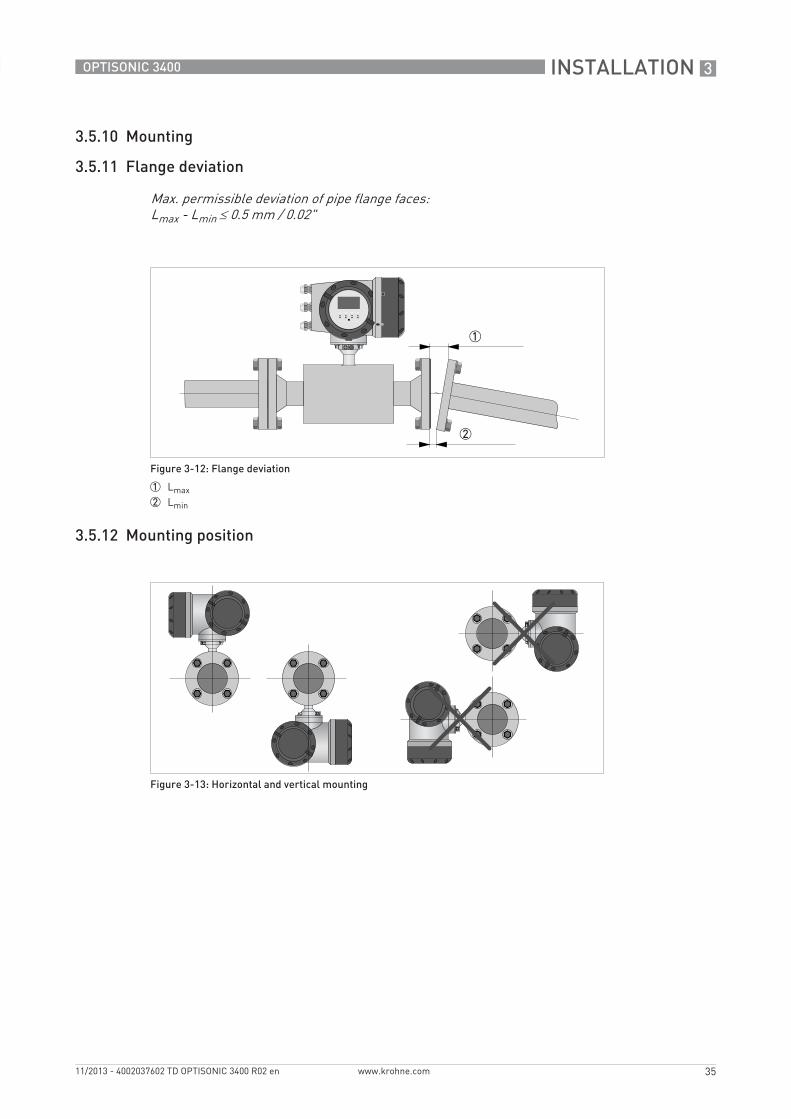
3.5.10 Mounting
3.5.11 Flange deviation
3.5.12 Mounting position
Max. permissible deviation of pipe flange faces: Lmax - Lmin ≤ 0.5 mm / 0.02"
Figure 3-12: Flange deviation
1 Lmax2 Lmin
Figure 3-13: Horizontal and vertical mounting

4 ELECTRICAL CONNECTIONS
36
OPTISONIC 3400
www.krohne.com 11/2013 - 4002037602 TD OPTISONIC 3400 R02 en
4.1 Safety instructions
4.2 Signal cable (remote versions only)
The flow sensor is connected to the signal converter via one signal cable, with 6 (labeled) inner coax cables for the connection of three acoustic paths.
All work on the electrical connections may only be carried out with the power disconnected. Take note of the voltage data on the nameplate!
Observe the national regulations for electrical installations!
For devices used in hazardous areas, additional safety notes apply; please refer to the Ex documentation.
Observe without fail the local occupational health and safety regulations. Any work done on the electrical components of the measuring device may only be carried out by properly trained specialists.
Look at the device nameplate to ensure that the device is delivered according to your order. Check for the correct supply voltage printed on the nameplate.
Figure 4-1: Construction of field version
1 Signal converter2 Open connection box3 Tool for releasing connectors4 Marking on cable5 Insert cable(s) into terminal compartment
Connect the cable on connector with similar numeral marking

ELECTRICAL CONNECTIONS 4
37
OPTISONIC 3400
www.krohne.com11/2013 - 4002037602 TD OPTISONIC 3400 R02 en
4.3 Power supply
100…230 VAC• Connect the protective ground conductor PE of the mains power supply to the separate
terminal in the terminal compartment of the signal converter.• Connect the live conductor to the L terminal and the neutral conductor to the N terminal.
24 VAC/DC• Connect a functional ground FE to the separate U-clamp terminal in the terminal
compartment of the signal converter.• When connecting to functional extra-low voltages, provide a facility for protective separation
(PELV) (VDE 0100 / VDE 0106 and/or IEC 364 / IEC 536 or relevant national regulations).
When this device is intended for permanent connection to the mains. It is required (for example for service) to mount an external switch or circuit breaker near the device for disconnection from the mains. It shall be easily reachable by the operator and marked as the disconnecting the device for this equipment.The switch or circuit breaker and wiring has to be suitable for the application and shall also be in accordance with the local (safety) requirements of the (building) installation(e.g. IEC 60947-1 / -3)
The power terminals in the terminal compartments are equipped with additional hinged lids to prevent accidental contact.
1 100...230 VAC (-15% / +10%), 22 VA2 24 VAC/DC (AC: -15% / +10%; DC: -25% / +30%), 22 VA or 12 W
The device must be grounded in accordance with regulations in order to protect personnel against electric shocks.

4 ELECTRICAL CONNECTIONS
38
OPTISONIC 3400
www.krohne.com 11/2013 - 4002037602 TD OPTISONIC 3400 R02 en
4.4 Inputs and outputs, overview
4.4.1 Combinations of the inputs/outputs (I/Os)
This signal converter is available with various input/output combinations.
Basic version• Has 1 current output, 1 pulse output and 2 status outputs / limit switches.• The pulse output can be set as status output/limit switch and one of the status outputs as a
control input.
Ex i version• Depending on the task, the device can be configured with various output modules.• Current outputs can be active or passive.• Optionally available also with Foundation Fieldbus and Profibus PA
Modular version• Depending on the task, the device can be configured with various output modules.
Bus systems• The device allows intrinsically safe and non intrinsically safe bus interfaces in combination
with additional modules.• For connection and operation of bus systems, please note the separate documentation.
Ex option• For hazardous areas, all of the input/output variants for the housing designs C and F with
terminal compartment in the Ex d (pressure-resistant casing) or Ex e (increased safety) versions can be delivered.
• Please refer to the separate instructions for connection and operation of the Ex-devices.

ELECTRICAL CONNECTIONS 4
39
OPTISONIC 3400
www.krohne.com11/2013 - 4002037602 TD OPTISONIC 3400 R02 en
4.4.2 Description of the CG number
The last 3 digits of the CG number (5, 6 and 7) indicate the assignment of the terminal connections. Please refer to the following examples.
Examples for CG number
Description of abbreviations and CG identifier for possible optional moduleson terminals A and B
Figure 4-2: Marking (CG number) of the electronics module and input/output variants
1 ID number:2 ID number: 0 = standard3 Power supply option4 Display (language versions)5 Input/output version (I/O)6 1st optional module for connection terminal A7 2nd optional module for connection terminal B
CG 350 11 100 100...230 VAC & standard display; basic I/O: Ia or Ip & Sp/Cp & Sp & Pp/Sp
CG 350 11 7FK 100...230 VAC & standard display; modular I/O: Ia & PN/SN and optional module PN/SN & CN
CG 350 81 4EB 24 VDC & standard display; modular I/O: Ia & Pa/Sa and optional module Pp/Sp & Ip
Abbreviation Identifier for CG No. Description
Ia A Active current output
Ip B Passive current output
Pa / Sa C Active pulse output, frequency output, status output or limit switch (changeable)
Pp / Sp E Passive pulse output, frequency output, status output or limit switch (changeable)
PN / SN F Passive pulse output, frequency output, status output or limit switch acc. to NAMUR (changeable)
Ca G Active control input
Cp K Passive control input
CN H Active control input to NAMURSignal converter monitors cable breaks and short circuits acc. to EN 60947-5-6. Errors indicated on LC display. Error messages possible via status output.
- 8 No additional module installed
- 0 No further module possible
4 ELECTRICAL CONNECTIONS
40
OPTISONIC 3400
www.krohne.com 11/2013 - 4002037602 TD OPTISONIC 3400 R02 en
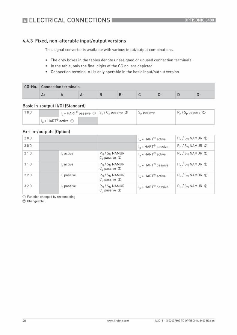
4.4.3 Fixed, non-alterable input/output versions
This signal converter is available with various input/output combinations.
• The grey boxes in the tables denote unassigned or unused connection terminals.• In the table, only the final digits of the CG no. are depicted.• Connection terminal A+ is only operable in the basic input/output version.
CG-No. Connection terminals
A+ A A- B B- C C- D D-
Basic in-/output (I/O) (Standard)1 0 0 Ip + HART® passive 1 Sp / Cp passive 2 Sp passive Pp / Sp passive 2
Ia + HART® active 1
Ex-i in-/outputs (Option)2 0 0 Ia + HART® active PN / SN NAMUR 2
3 0 0 Ip + HART® passive PN / SN NAMUR 2
2 1 0 Ia active PN / SN NAMURCp passive 2
Ia + HART® active PN / SN NAMUR 2
3 1 0 Ia active PN / SN NAMURCp passive 2
Ip + HART® passive PN / SN NAMUR 2
2 2 0 Ip passive PN / SN NAMURCp passive 2
Ia + HART® active PN / SN NAMUR 2
3 2 0 Ip passive PN / SN NAMURCp passive 2
Ip + HART® passive PN / SN NAMUR 2
1 Function changed by reconnecting2 Changeable

ELECTRICAL CONNECTIONS 4
41
OPTISONIC 3400
www.krohne.com11/2013 - 4002037602 TD OPTISONIC 3400 R02 en
4.4.4 Alterable input/output versions
This signal converter is available with various input/output combinations.
• The grey boxes in the tables denote unassigned or unused connection terminals.• In the table, only the final digits of the CG no. are depicted.• Term. = (connection) terminal
CG no. Connection terminals
A+ A A- B B- C C- D D-
Modular IOs (option)4 _ _ max. 2 optional modules for term. A + B Ia + HART® active Pa / Sa active 1
8 _ _ max. 2 optional modules for term. A + B Ip + HART® passive Pa / Sa active 1
6 _ _ max. 2 optional modules for term. A + B Ia + HART® active Pp / Sp passive 1
B _ _ max. 2 optional modules for term. A + B Ip + HART® passive Pp / Sp passive 1
7 _ _ max. 2 optional modules for term. A + B Ia + HART® active PN / SN NAMUR 1
C _ _ max. 2 optional modules for term. A + B Ip + HART® passive PN / SN NAMUR 1
PROFIBUS PAD _ _ max. 2 optional modules for term. A + B PA+ (2) PA- (2) PA+ (1) PA- (1)
FOUNDATION Fieldbus (option)E _ _ max. 2 optional modules for term. A + B V/D+ (2) V/D- (2) V/D+ (1) V/D- (1)
Modbus (option)G _ _ 2 max. 2 optional modules for term. A + B Commo
nSign. B (D1)
Sign. A (D0)
1 changeable2 not activated bus terminator
5 APPLICATIONS
42
OPTISONIC 3400
www.krohne.com 11/2013 - 4002037602 TD OPTISONIC 3400 R02 en
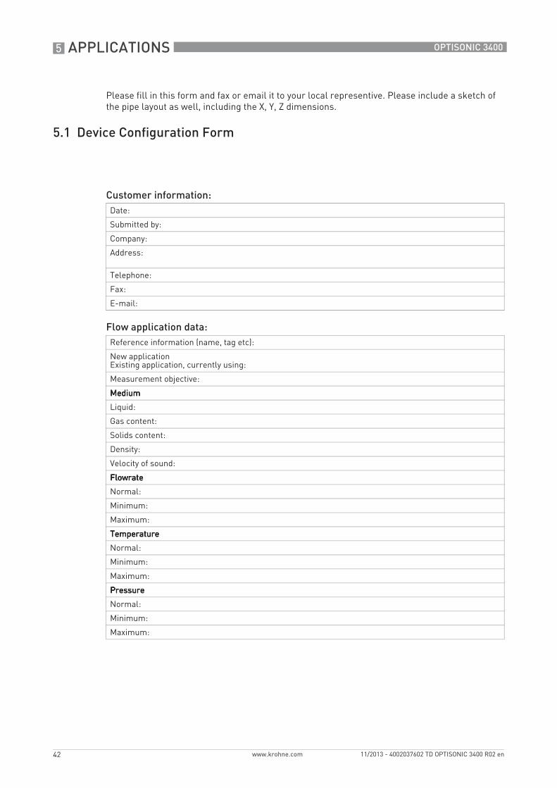
Please fill in this form and fax or email it to your local representive. Please include a sketch of the pipe layout as well, including the X, Y, Z dimensions.
5.1 Device Configuration Form
Customer information:Date:
Submitted by:
Company:
Address:
Telephone:
Fax:
E-mail:
Flow application data:Reference information (name, tag etc):
New applicationExisting application, currently using:
Measurement objective:
MediumMediumMediumMedium
Liquid:
Gas content:
Solids content:
Density:
Velocity of sound:
FlowrateFlowrateFlowrateFlowrate
Normal:
Minimum:
Maximum:
TemperatureTemperatureTemperatureTemperature
Normal:
Minimum:
Maximum:
PressurePressurePressurePressure
Normal:
Minimum:
Maximum:
APPLICATIONS 5
43
OPTISONIC 3400
www.krohne.com11/2013 - 4002037602 TD OPTISONIC 3400 R02 en
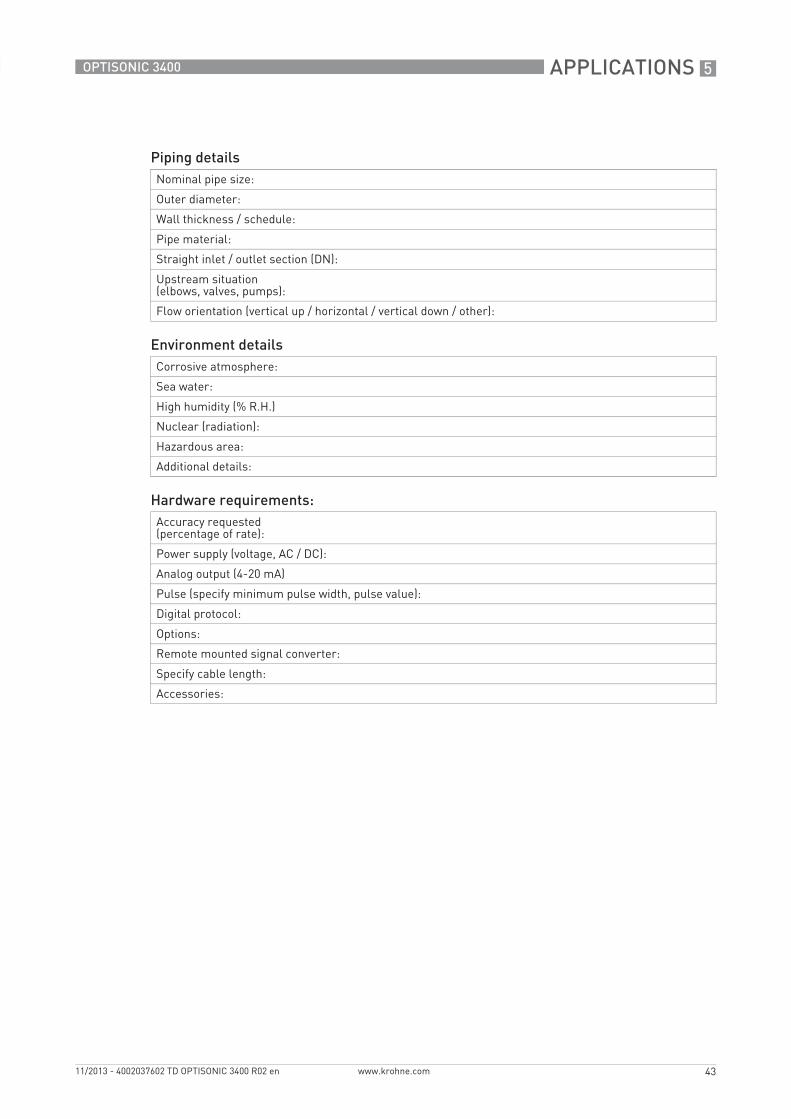
Piping detailsNominal pipe size:
Outer diameter:
Wall thickness / schedule:
Pipe material:
Straight inlet / outlet section (DN):
Upstream situation (elbows, valves, pumps):
Flow orientation (vertical up / horizontal / vertical down / other):
Environment detailsCorrosive atmosphere:
Sea water:
High humidity (% R.H.)
Nuclear (radiation):
Hazardous area:
Additional details:
Hardware requirements:Accuracy requested (percentage of rate):
Power supply (voltage, AC / DC):
Analog output (4-20 mA)
Pulse (specify minimum pulse width, pulse value):
Digital protocol:
Options:
Remote mounted signal converter:
Specify cable length:
Accessories:

KROHNE product overview
• Electromagnetic flowmeters
• Variable area flowmeters
• Ultrasonic flowmeters
• Mass flowmeters
• Vortex flowmeters
• Flow controllers
• Level meters
• Temperature meters
• Pressure meters
• Analysis products
• Products and systems for the oil & gas industry
• Measuring systems for the marine industry
Head Office KROHNE Messtechnik GmbHLudwig-Krohne-Straße 547058 Duisburg (Germany)Tel.:+49 203 301 0Fax:+49 203 301 103 89 [email protected]
© K
RO
HN
E 11
/201
3 -
4002
0376
02 T
D O
PTI
SON
IC 3
400
R02
en
- Su
bjec
t to
chan
ge w
ithou
t not
ice.
The current list of all KROHNE contacts and addresses can be found at:www.krohne.com
Top Related