


![STANDOX PEUGEOT 2010 [Kompatibilitätsmodus] · PEUGEOT MODELS / MODELLE 01 VIN / TYPENSCHILD 106 106 Electric 107 205 205 Cabrio 206 206+ 206 CC 206 Iran 207 207 Coupé 207 SW 207](https://static.fdocuments.in/doc/165x107/5eb93d842c6ab2124e1d96ca/standox-peugeot-2010-kompatibilittsmodus-peugeot-models-modelle-01-vin-typenschild.jpg)
Languages
Pages
Legal


OPERATOR’S MANUAL
WORK SAFELY AT ALL TIMES
WITH QUALIFIED OPERATORS ONLY.
MODEL SERIAL#
We, the undersigned, have read and understand the OPERATOR�S MANUAL.
QUALIFIED OPERATORS
NAME SHIFT DA TE
Safety glasses are required when operating or observing this machine. Modification or alteration of this
machine may be hazardous. Do not modify or alter this machine without Scotchman�s written
permission. Lesser quality parts may lead to injury.
SCOTCHMAN INDUSTRIES, INC.
P.O. BOX 850180 E. HIGHWAY 14
PHILIP, S.D. 57567-0850
(605) 859-2542 FAX # (605) 859-2499
MODEL 207

SCOTCHMAN
INDUSTRIES, INC.
MODEL
207
OPERATOR’S
MANUAL
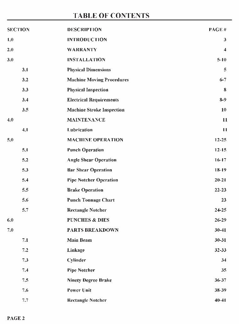
TABLE OF CONTENTS
SECTION DESCRIPTION PAGE #
1.0 INTRODUCTION 3
2.0 WARRANTY 4
3.0 INSTALLATION 5-10
3.1 Physical Dimensions 5
3.2 Machine Moving Procedures 6-7
3.3 Physical Inspection 8
3.4 Electrical Requirements 8-9
3.5 Machine Stroke Inspection 10
4.0 MAINTENANCE 11
4.1 Lubrication 11
5.0 MACHINE OPERATION 12-25
5.1 Punch Operation 12-15
5.2 Angle Shear Operation 16-17
5.3 Bar Shear Operation 18-19
5.4 Pipe Notcher Operation 20-21
5.5 Brake Operation 22-23
5.6 Punch Tonnage Chart 23
5.7 Rectangle Notcher 24-25
6.0 PUNCHES & DIES 26-29
7.0 PARTS BREAKDOWN 30-41
7.1 Main Beam 30-31
7.2 Linkage 32-33
7.3 Cylinder 34
7.4 Pipe Notcher 35
7.5 Ninety Degree Brake 36-37
7.6 Power Unit 38-39
7.7 Rectangle Notcher 40-41
PAGE 2

1.0 INTRODUCTION
The Scotchman Ironworker is a versatile, multi-purpose, shearing, punching and forming machine en-
gineered for trouble free operation. The design of the machine combines simplicity of operation with
smooth, full stroke control. The ability of the operator to control the machine�s direction of movement at
any point in the stroke (stop, jog or reverse) gives the Scotchman Ironworker a tremendous advantage
over mechanical machines. There is no chance of the Scotchman Ironworker being "accidentally
tripped". The hydraulic system operates at a maximum pressure of 1,500 PSI and is protected from
overload by a pilot operated relief valve.
PAGE 3

2.0 WARRANTY
Scotchman Industries, Inc. will, within one (I) year of date of purchase, replace F.O.B. the factory or
refund the purchase price for any goods which are defective in materials and workmanship, provided
that the buyer returns the warranty registration card within thirty (30) days of purchase date and, at the
seller�s option, returns the defective goods freight and delivery prepaid to the seller, which shall be the
buyer�s sole and exclusive remedy for defective goods. Hydraulic and electrical components are subject to
their respective manufacturer�s warranties. This warranty does not apply to machines and/or
components which have been altered, changed or modified in any way or subjected to abusive and
abnormal use, inadequate maintenance and lubrication or subjected to use beyond seller�s recommended
capacities and specifications. In no event shall seller be liable for labor costs expended on such goods or
consequential damages. Seller shall not be liable to purchaser or any other person for loss or damage,
directly or indirectly arising from the use of the goods or from any other cause. No officer, employee or
agent of seller is authorized to make any oral representations or warranty of fitness or to waive any of the
foregoing terms of sale and none shall be binding on the seller .
PAGE 4

3.0 INSTALLATION
Ö CAUTION: THIS SECTION DISCUSSES INSTALLATION AND SET-UP PROCEDURES.
PLEASE READ THOROUGHLY BEFORE OPERATING THIS IRONWORKER.
3.1 PHYSICAL DIMENSIONS
HEIGHT 48 INCHES
LENGTH 33 INCHES
WIDTH 24 INCHES
WEIGHT 550 POUNDS
PAGE 5
FIGURE 1

3.2 MACHINEMOVING PROCEDURES
There are two recommended methods of moving the Model 207.
Ö CAUTION: MAKE SURE THAT ANY LIFTING DEVICE HAS ADEQUATE CAPACITY
BEFORE ATTEMPTING TO PICK UP THE MACHINE.
The 207 does not have to be level or stationary to operate. FIGURE 2 demonstrates the use of a forklift.
For safety purposes, the forks should be spread so as to fit just inside the legs of the machine. Lift only on
the square tubing side rails or under the 2 x 4 skids. Do not back away from the machine with the forks
tilted up, as this could cause interior damage to the machine.
PAGE 6
FIGURE 2

FIGURE 3 demonstrates an overhead lift for the Model 207.
* NOTE: The lift must not be made on the beam by wrapping the chain or strap between the pivot pin
and the top angle blade holder area of the beam, as that may damage the control linkage or .move it
out of adjustment.
To lift the 207, hook one end of a chain in the vertical plate welded on top of the beam support ears. Re-
.move the hold down roller and run the other end of the chain through the right hand hold down bracket,
Place the right hand allen wrench back in its place, passing through one of the chain links, to hold it in
place. The chain may now be used to lift the 207.
PAGE 7
FIGURE 3

3.3 PHYSICAL INSPECTION
Any damage to the machine during shipment should be reported to the delivery carrier immediately and
a damage report made out so that a claim can be placed. The carrier is responsible for shipping damage,
but it is the customer�s responsibility to report damages, external or internal, immediately.
After the machine has been located, the shroud on the operator�s side of the machine should be removed
and an inspection made of the interior of the machine for missing or damaged parts.
CHECK SPECIFICALLY:
A. The foot pedal linkage should operate freely, all pins and keys in place.
B. The spool should work freely in the valve.
C. Check all nuts, especially on the base of the motor and pump, to be sure that they are tight.
D. Check the hydraulic oil level in the tank. It should be 1-1/2 to 2-1/2 inches below the top of the tank.
E. The machine should be received with the punch in the down position, the punch being inserted in the
die. This insures that the punch and die have not been knocked out of alignment in shipment. If the
punch is in the up position when you receive your machine, align your punch and die before
operating your 207. For instructions, SEE SECTION B ON PAGE 13.
3.4 ELECTRICAL REQUIREMENTS
All machines are wired 230V -3 Phase-60 Hz unless order is specified otherwise. (Motors are dual voltage
230-460 and may be rewired for higher voltage per instructions on the motor. Switch boxes are NOT dual
voltage and a new box must be supplied with a voltage changeover.)
Ö CAUTION: TO PREVENT DAMAGE TO THE MOTOR AND DANGER TO THE OPERATOR,
ALL ELECTRICAL CONNECTIONS SHOULD BE MADE BY A LICENSED ELECTRICIAN.
For supply cords ten foot or shorter, we recommend at least 12 gauge and preferably, 10 gauge. For
longer cords, use at least 10 gauge and preferably, 8 gauge. After connecting the electrical power and
making physical inspection, remove all objects (tools, wrenches etc.) away from the work area on the
machine. Turn the machine on momentarily and note the rotation of the motor and pump. Rotation is
indicated on the pump. If the rotation is not correct, the electrician will have to switch two of the three
input wires.
MOTOR VOLTAGE (V AC) FULL LOAD CURRENT (AMPS)
208/3 ph 9.7
230/3 ph 8.8
460/3 ph 4.4
220/1 ph 19.5
PAGE 8

PAGE 9
FIGURE 4

3.5 MACHINE STROKE INSPECTION
The OVERALL STROKE on the 207 has been pre-set correctly at the factory, but should be checked to
see that the linkage has not worked loose or damage occurred during shipment. Set the stroke adjustment
handles as far apart as possible. (For parts identification, SEE FIGURE 5.) With the machine running,,
set the select lever to PUNCH mode. Be sure that 2 x 2 x 1/4 angle iron will fit into the angle shear. If not,
loosen the bolt on the stroke adjustment block and raise the block until adequate clearance, to just let
the 2 x 2 x 1/4 angle pass through freely, is obtained. Now, set the select lever to SHEAR mode. The
blades should be open about 1/8" at the closest point. If there is not at least 1/8" opening, the clearance on
the 2 x 2 x 1/4 angle has been set too great and the stroke adjustment block will have to be lowered.
PAGE 10
FIGURE 5

4.0 MAINTENANCE
The Scotchman Ironworker is an exceptionally �rugged� machine designed for long life with a minimum
.amount of maintenance. A regular program of servicing will extend the machine�s life and prevent costly
downtime.
4.1 LUBRICATION
Ü IMPORT ANT: Before operating the 207, apply oil to the bar shear blades, the angle shear blades
and the punch and die.
Re-oil punches and dies every five to ten cuts and blades every 10 to 15 cuts. The oil will allow the
machine to shear, punch and strip more easily and increase tool life considerably. We recommend cutting
oil or motor oil swabbed on with a small brush or applied with a squirt can or a spray applicator. Apply
.oil to the clevis pin.
LUBRICATION CHART
ONCE PER DAY:
1. Grease the zerk on the beam pivot pin.
2. Grease the four zerks, located around the angle shear on the operator�s side of the machine.
3. Grease the two zerks on the pressure plate ( one in each end).
ONCE PERWEEK:
1. Grease the zerk in the pressure block on top of the punch ram.
2. Grease the zerk on the side of the punch barrel guide.
3. Apply grease to the surface of the beam guide wear plates on the outer end of the main beam (parts
3 and 4 on page 24).
ONCE PER YEAR:
Change the hydraulic oil. Disconnect the hydraulic hose that runs from the tank to the pump at the
bottom of the tank and allow it to drain. Refill with approximately ten quarts of medium weight, non-
foaming hydraulic oil. The oil level needs to be 1-1/2" to 2" from the top of the tank.
PAGE 11

5.0 MACHINE OPERATION
Each operator should familiarize himself with the following practices and safety precautions.
5.1 PUNCH OPERATION
A. SELECT THE PROPER PUNCH AND DIE.
The 207 Ironworker uses the #20 punches and dies that have a built-in clearance of 1/32 of an inch.
Under normal punching conditions, a punch will use a corresponding die stamped the same size.
(A 3/8" punch will be used with a die stamped 3/8".) In some cases, when punching 1/2" thick steel or
material harder than mild steel, it may be desirable to use a 1/16" larger die, which will reduce the
tonnage requirements and provide less shock.
PAGE 12
FIGURE 6 (PUNCH PART IDENTIFICATION)

B. INSTALLING PUNCHES AND DIES.
1. Turn the machine on and put the changeover lever in SHEAR position. This will run the punch
down into the die, which is necessary for the proper alignment of the new punch and die.
2. Remove the stripper guard and the stripper.
3. Completely loosen the two bolts that hold the die holder in place. Raise the die holder and remove
the 1/2" spacer plate from under it. Now the die holder can be removed from the machine.
4. Loosen the set screw in the front side of the die holder and remove the die. Insert the new die so that
the ground flat area aligns with the set screw. Then, tighten the screw.
5. Remove the punch retaining nut and punch. Install the new punch and tighten it firmly in place. (If
a square or slot punch is being used, do not tighten the retaining nut until after the die holder is put
back into place. This is necessary to obtain proper alignment.)
6. Place the die holder so that the punch enters the die, then lift it up to allow the 1/2" spacer plate to
be put back under the die holder. Adjust the die holder so that there is equal clearance between the
punch and die on all sides. Tighten the two die holder bolts firmly. (Tighten the punch retaining nut
at this time, if a square or slot punch is being used.)
7. Install the stripper, stripper washers and guard. The washers are used to reduce the clearance be-
tween the stripper and the material being punched. The stripper should be lowered so that the mate-
rial will just pass under it freely. This will reduce stripping time. If a variety of material thicknesses
will be punched, no washers should be installed.
8. Adjust the stroke control handles to provide the minimum stroke required for each job. This will de-
crease cycle time.
C. LUBRICATE THE PUNCH AND DIE.
Oil should be applied before the first hole is punched and every 5 to 10 cuts, thereafter. This will in-
crease punch life considerably and allow the machine to punch and strip more easily.
D. CHECK PUNCHING TOOLS FOR TIGHTNESS.
Tools should be checked at the start of each operation and intermittently during the day. Check the
punch securing nut, stripper, die and die holder. Tools tend to loosen under punching shock. Keep
them tight to prevent punch to die contact.
E. CONTACT BOTH SIDES OF THE STRIPPER. Material to be punched must contact or straddle
both sides of the stripper. An unbalanced stripping load will occur, causing punch breakage, if this
practice is not observed.
PAGE 13

F . SPECIAL STRIPPERS MAY BE NEEDED FOR CERT AIN JOBS.
The standard stripper has been designed to work in as many applications as possible, but you may
have to fabricate your own strippers for some materials, small channel for example. The important
consideration is to keep material level through the stripping action. When punching thin strap iron,
the material will tend to draw up into the stripper. To prevent this, a large washer can be welded
across the bottom of the stripper to force materials to strip off level. This type of stripper will also
allow you to punch in the corner of metal pieces.
G. SMALL ANGLE IRON MAY DAMAGE THE PUNCH RETAINING NUT.
Ö CAUTION: WHEN PUNCHING ANGLEWITH AN UPRIGHT LEG OF 1 TO 2-1/2", AS THE
PUNCH COMES DOWN, THE RETAINING NUT MAY STRIKE THE UPRIGHT LEG,
DAMAGING THE NUT.
H. STAYWITHIN RA TED PUNCHING CAPACITIES.
* NOTE: 1/2" material is the maximum thickness for punching.
Your Scotchman Ironworker is designed to operate in mild steel. Within conservative limits, it can
also operate in medium carbon annealed steel and some forms of abrasion resistant steels.
Conditions of high shock can be encountered in the punching of alloyed steels and accordingly, the
machine rating must be reduced.
I. DO NOT PUNCHMATERIAL THICKER THAN THE DIAMETER OF THE PUNCH.
This "rule of thumb" is a safety factor. If the material is thicker than the punch size, breakage is
very likely.
PAGE 14
MAXIMUM PUNCH SIZES IN MILD STEEL
Thickness of Steel Diameter of Punch
1/2" 1/2"
3/8" 21/32"
1/4" 1"
3/16" 1-1/4"
FIGURE 7

I. PUNCH FULL, COMPLETE HOLES. DO NOT PUNCH PARTIAL HOLES OR PAST THE
EDGE OF THE MATERIAL.
The side thrust encountered in punching a partial hole can force the punch over and strike the die,
causing punch or die breakage. (If long slots need to be punched requiring three or more strokes,
punch both ends out first, leaving the center section for the last stroke.) Special nibbling punch and
die sets are available for punching into the edge of material. Call Scotchman Industries for
quotations.
J. MAINTAIN SUFFICIENT MATERIAL BETWEEN THE PUNCHED HOLE AND THE EDGE OF
THEWORKPIECE.
If a hole is punched very near the edge of the material, it will deform the workpiece. A rule of
thumb is �Do not punch closer to the edge of the material than a distance equal to the material
thickness�.
K. DO NOTWORKWITH DULL OR DAMAGED TOOLING.
Working with damaged punches or dies will increase the tonnage requirements and tend to
overwork the machine. It will also produce less desirable holes.
PAGE 15
FIGURE 8

5.2 ANGLE SHEAR OPERATION
A. LUBRICATE THE BLADES.
Oil should be applied to the upper and lower blades before the first cut is made and every 10 to 15
cuts, thereafter. This will reduce cutting pressures and increase blade life.
B. SHEARWITHIN RA TED CAPACITIES.
The 207 angle shear is designed to shear a maximum of 1/4" material.
C. TO INSURE A SQUARE CUT: Adjust the angle cutting guide for each change in angle thickness.
D. UNEQUAL LEG ANGLE CAN BE SHEAREDWITHOUT SPECIAL BLADES.
E. WHEN LARGE QUANTITIES OF LIGHT ANGLE ARE BEING CUT:
The stroke control handles should be set to provide minimum stroke, which will save time.
F. DO NOTWORKWITH DULL OR DAMAGED BLADES OR ALLOW EXCESSIVE GAP
BETWEEN THE BLADES.
If blades become chipped or dull, they should be replaced. Lower angle blades may be turned once
to expose a new cutting edge. For best results, about .005 inch clearance per side should be
maintained between the upper and lower blades. Shim behind the lower blades to reduce clearance.
PAGE 16
FIGURE 9 (ANGLE SHEAR PARTS IDENTIFICATION)

G . KE EP THE CUTOFF AREA CLEAR.
Shortcuts and slivers will tend to build up on the cutoff side. These pieces must be cleared off to
prevent buildup. To prevent unnecessary wear, the clevis pin may be removed from the beam when
the angle shear is not in use.
H. CHANGING BOTTOM ANGLE BLADES:
1. Loosen, but. do not remove, the two flathead screws holding the blades to the angle blade holder.
2. Remove the blade holder from the frame by unscrewing the three flathead screws holding it.
3. Remove both blades from the angle blade holder and reverse them, moving the top blade to the bot-
tom position and vise versa, so that the new cutting edges are exposed. If the blades have already
been turned once, replace them with new blades. Tighten the screws finger tight, to hold the blades
in place.
4. Put the plate, with the blades attached, back on the machine and re-tighten the three flathead screws
by hand.
5. Make sure that the bottom of the blades are seated flat in the frame and that no gap exists between
the two blades.
6. Tighten all five screws with a wrench.
I. CHANGING THE TOP ANGLE SHEAR BLADE:
1. Remove the angle guide.
2. Turn the machine on, switch the select lever to PUNCH and run the machine forward until the top
blade is completely visible. Shut the machine off in this position.
3. Remove the flathead allen screw.
4. Remove the blade from the beam.
5. With a clean grease rag and an air nozzle, blow away and clean all dirt and foreign matter that
could keep the blade from lying flat in the beam cavity.
6. Insert the new blade and tighten it securely.
7. Remove all foreign objects from the shear and punch area. Start the machine and jog it slowly for-
ward, making sure that the blade does not overlap with the bottom blades.
8. Turn off the machine and attach the angle guide.
* NOTE: The cutting edge of the top blade and the cutting edge of the bottom blade should be parallel
when the top and bottom are 1/8" apart. If not, the blades should be loosened and adjusted top
provide the best cuts.
PAGE 17

5.3 BAR SHEAR OPERATION
A. LUBRICATE THE BLADES. Apply oil to the blades before making the first cut and every 10 to 15
cuts, thereafter. This will reduce cutting tonnage and increase blade life.
B. LESS DISTORTION AT OUTER END OF BLADES. Bar blades on the 207 do not have a fixed
rake and, therefore, have less distortion toward the outer end. For minimum distortion, it may be
desirable to shear thinner metal as far to the right hand side as capacity will allow. Thicker pieces
will have to be sheared closer to the pivot area, to provide required tonnage.
C. ROUNDS AND SQUARES MAY BE CUT ON THE BAR SHEAR. Round rods, square bars and
other shapes may be sheared on the standard bar blades, but a slight amount of distortion will
occur, a flattening on one side of the rod. This type of cut is satisfactory for most welding purposes,
but cannot be threaded or fed through a tight clearance without first grinding. To cut many shapes
with minimum distortion, notched bar blades that will fit in the bar shear area are available. For
diagrams, SEE FIGURE 10 ON THE FOLLOWING PAGE.
D. MAINTAIN PROPER BLADE CLEARANCE. A clearance of .005 inch should be maintained
between the bar blades, the full length of the blades. Clearance is reduced by placing shims behind
the lower blade. If the beam moves away from the lower blade on each stroke, it is necessary to ad-
just or shim the beam guide located on the back side, outer end of the beam, to guide the beam down
in a straight line.
E. HARD MATERIALS MAY DAMAGE BLADES. The 207 is designed for shearing mild steel, SAE-
1020. Within conservative limits, it can also operate in medium carbon annealed steel, some stainless
and some forms of abrasion resistant steels. Shearing capacities will be reduced as these materials
shear harder. Some materials, such as hardened tool steel, will damage or break blades and should
not be sheared. Concrete reinforcement bar can be sheared, but has hard spots and will cause the
blades to wear more rapidly.
F. KEEP THE CUT -OFF AREA CLEAR. Short cuts and slivers will tend to build up when sheared on
the bar shear. These pieces should be cleared off before buildup develops.
G. BAR SHEAR CAPACITIES.
Maximum Shearing Capacity in Mild Steel:
Thickness of Steel Length of Cut
1/2" 3"
3/8" 5"
1/4" 7"
PAGE 18

PAGE 19
FIGURE 10
Figure 10 features SPECIAL NOTCHED BAR
BLADES FOR CUTTINGWITH MINIMUM
DISTORTION. These are some of the more common
notches we provide in blades, to produce minimum
distortion cuts. We will also build blades for other
shapes. If you have some material that you need to
cut without distortion, send us a sample or call us for
feasibility and price.
Figure 11 below features examples of various shapes that we can provide for hole punching. We also
custom build other shapes upon request. Send us samples or drawings of what you need and we will
quote price and delivery, if your operation is feasible.
FIGURE 11

5.4 PIPE NOTCHER
The Pipe Notcher is a component tool designed to saddle cut pipe or tubing for applications such as
railings. There are dies available to notch angles in tubes and pipe, also. For prices and availability,
contact your local dealer or the factory.
5.4A PIPE NOTCHER INSTALLATION
SEE FIGURE 11A ON THE FOLLOWING PAGE. The Pipe Notcher installs in the punch station on this
model. When installed in the punch station, the selector arm must be in the PUNCH position.
TO MOUNT THE PIPE NOTCHER IN THE PUNCH STATION:
1. Remove the die holder, die holder plate, stripper, punch and punch retaining nut.
2. Install the punch pusher (A) in the punch barrel.
3. Install the return springs, the upper die and the lower die in the pipe notcher housing.
4. Mount the pipe notcher so that the cutting dies face to the left, or right side of the machine. Use one
of the die holder bolts to anchor the tool in place. To assure proper slug removal, align the tool over
the slug hole in the bolster.
* NOTE: THE PUNCH PUSHERWILL NOT ALIGN DIRECTLY OVER THE PIPE NOTCHER.THIS IS OKA Y.
Ö CAUTION: WITH THE TOOL MOUNTED, IT IS NECESSARY TO SET THE DOWNSTROKEOF THE MACHINE TO PREVENT DAMAGE TO THE TOOL. THE UPPER DIE SHOULD NOTPASS THE LOWER DIE BY MORE THAN 1/32 OF AN INCH (.7MM).
5.4B PIPE NOTCHER OPERATION
The Pipe Notcher is a vendor item for Scotchman Industries. The following are the manufacturer�s
recommendations for maintenance and alignment of this tool.
Ü PLEASE READ CAREFULLY BEFORE USE OF TOOLING.
To achieve the best results from your unit, please observe these simple rules:
A. Keep the unit clean. Whenever dirt or metal chips accumulate, remove the 8mm limit screw located
in the center, at the rear of the punch. Lift out the punch holder and the two springs. Clean the unit
with solvent.
B. Never remove the M-10 dowel pin from the upper die.
C. Check the alignment of the unit. After cleaning the unit, always check the alignment of the punchand die. To check the alignment, insert the punch and die holder, without the springs, into thehousing and check the gap. SEE FIGURE 11B ON THE FOLLOWING P AGE. If proven correct,tighten the two M-10 socket head screws holding the lower die section in place. Apply some highpressure lube all around the inside of the housing. Reassemble the unit, reversing the aboveprocedures. Before operating, lubricate the back and sides of the upper die with way oil. Repeat thislubrication once daily. Apply cutting oil or motor oil to the cutting dies before the first cut and everyten to fifteen cuts, thereafter.
PAGE 20

5.4C PIPE NOTCHER CAPACITIES
One and one half inch (1-1/2") schedule 80 pipe is the maximum thickness that can be cut. Lighter weight
tubing may be cut, but will probably require different dies for best cutting results. Separate dies .are
required for each size of pipe or tubing being notched.
Ö CAUTION: ALWAYS REMOVE THIS TOOLWHEN IT IS NOT IN USE.
PAGE 21

5.5 BRAKE OPERATION
A. INSTALLATION:
1. The brake is installed in the punch station. Remove the die holder and spacer, the stripper, punch
and retaining nut.
2. Install the upper die in place of the punch, but do not tighten the retaining nut at this time.
3. Bolt the brake base in place of the die holder, using the two bolts from the die holder. Do not tighten
at this time.
4. Put the lower brake die in the base and jog the beam down carefully, until the dies come together.
Rotate the upper die and move the base until the dies are aligned, then shut the machine off and
tighten the retaining nut on the upper die and bolts in the base.
5. Set the upper stroke control handle to prevent constant bottoming out of the dies. The stroke control
handle can be reset later, to provide the desired degree of bend on your material. The lower die may
be rotated to accommodate various thicknesses of material.
B. CAPACITIES:
1/4 x 6" is the maximum capacity. Narrower materials up to 3/8" thick may be bent by using a
wider, lower die and a larger radius or upper die.
C. CENTER MATERIAL: It is necessary to always center-load the material in the brake; otherwise,
damage will occur to the upper die.
PAGE 22

PAGE 23
FIGURE 12 (PUNCH TONNAGE CHART)

5.6 RECTANGLE NOTCHER
The Rectangle Notcher is a component tool designed to make rectangle and vee notches in angle iron and
flat stock. The maximum capacity of this tool is 2 by 1-3/4 inches (50 x 45mm) rectangle notch in 1/4 inch
(6mm) material or a 1-1/2 inch (38mm) vee notch.
5.6A RECTANGLE NOTCHER INSTALLATION
SEE FIGURE 13 ON THE FOLLOWING PAGE.
1. Place the selector arm in the PUNCH position and allow the cylinder to completely retract.
2. Remove the die holder, die holder plate, stripper, punch and punch retaining nut.
3. Insert the notcher ram (A) into the die (B) and place the tool on the punch bolster.
4. Start the punch retaining nut in the punch bolster.
5. Raise the die (B) and install the riser (C) under the die.
6. Start the mounting bolts (D) in the die and tighten the punch retaining nut.
7. Align the upper and lower dies and tighten the mounting bolts (D).
5.6B RECTANGLE NOTCHER OPERATION
Ö CAUTION: BEFORE OPERATING, THIS TOOL, SET THE DOWNSTROKE OF THE
MACHINE SO THAT THE FRONT OF THE TOP BLADE JUST PASSES THE LOWER
BLADES, APPROXIMATELY 1/8 INCH (.3MM). FAILURE TO SET THE STROKEWILL
RESULT IN DAMAGE TO THE TOOL AND POSSIBLE INJURY TO THE OPERATOR.
1. Lubricate the upper and lower dies before the first cut and every ten to fifteen cuts, thereafter.
2. Place the material to be notched between the upper and lower dies and make the cut.
3. After the cut is made, remove the material before releasing the foot pedal.
Ö CAUTION: ALWAYS REMOVE THIS TOOLWHEN IT IS NOT IN USE.
PAGE 24

PAGE 25
FIGURE 13

8.0 PUNCHES & DIES
#20 ROUND PUNCHES & DIES
1/8, 5/32, 3/16, 7/32, 1/4, 9/32,
5/16, 11/32, 3/8,13/32, 7/16,15/32,1/2,
17/32, 9/16, 19/32, 5/8, 21/32, 11/16,
23/32, 3/4,25/32, 13/16, 27/32,
7/8, 29/32, 15/16, 31/32,
1, 1-1/32, 1-1/16, 1-1/8, 1-3/16, 1-1/4
5mm, 6mm, 7mm, 8mm, 9mm, 10mm, 11mm, 12mm
13mm, 14mm, 15mm, 16mm, 17mm, 18mm, 19mm
20mm, 21mm, 22mm, 23mm, 24mm, 25mm
26mm, 27mm, 28mm, 29mm, 30mm, 31mm, 32mm
#20 ROUND OVERSIZED PUNCHES & DIES
(USE 2-5/8" DIE HOLDER)
1-9/32 � UP TO 2 �
#20 ROUND OVERSIZED PUNCHES & DIES
(USE 4 x 6 DIE)
2-1/32" UP TO 2-1/4"
#20 SQUARE PUNCHES & DIES
9/32, 3/8, 13/32, 7/16, 15/32, 1/2,
17/32, 9/16, 5/8, 21/32, 11/16, 3/4,
25/32, 13/16, 7/8, 1
PAGE 26

#20 OVAL SLOT PUNCHES & DIES
1/4 x 1/2, 9/32 x 1/2, 1/4 x 3/4, 9/32 x 3/4, 5/16 x 3/4,
11/32 x 3/4, 3/8 x 3/4,13/32 x 3/4, 7/16 x 3/4, 15/32 x 3/4,
1/2 x 3/4,17/32 x 3/4, 9/16 x 3/4,1/4 x 1, 9/32 x 1, 5/16 x 1,
11/32 x 1, 3/8 x 1, 13/32 x 1, 7/16 x 1, 15/32 x 1,1/2 x 1,
17/32 x 1, 9/16 x 1, 5/8 x 1, 21/32 x 1,11/16 x 1, 3/4 x 1,
25/32 x 1, 13/16 x 1,1/4 x 1-1/4, 5/16 x 1-1/4, 3/8 x 1-1/4,
13/32 x 1-1/4, 7/16 x 1-1/4, 15/32 x 1-1/4,1/2 x 1-1/4,
9/16 x 1-1/4, 5/8 x 1-1/4, 21/32 x 1-1/4,11/16 x 1-1/4,
3/4 x 1-1/4,25/32 x 1-1/4, 13/16 x 1-1/4
#20 OVAL SLOT OVERSIZED PUNCHES & DIES
(USE 2-5/8" DIE HOLDER)
1-9/32" UP TO 2"
#20 OVAL SLOT OVERSIZED PUNCHES & DIES
(USE 4 x 6 DIE)
2-1/32" UP TO 2-1/4"
PAGE 27

#20 PICKET PUNCHES & DIES
5/8 SQUARE TUBING MAX. ON 314-C6 & 4014-TM
3/4 SQUARE TUBING MAX. ON 4014-CM
#82 ECCENTRIC DIES FOR PUNCHING NEXT TOWEB OF ANGLE IRON
NOTE: ALL #82 ECCENTRIC DIES ARE 1/32" LARGER THAN PUNCH
SIZE.WHEN ORDERING, MUST SPECIFY PUNCH SIZE. EXAMPLE:
#20 1/2" PUNCHWILL NEED #82 17/32" ECCENTRIC DIE.
9/32, 5/16, 11/32, 3/8, 13/32, 7/16, 15/32, 1/2, 17/32, 9/16, 19/32,
5/8, 21/32, 11/16, 23/323/4, 25/32, 13/16, 27/32, 7/8, 29/32
#20 HEXAGON PUNCHES & DIES
(USE STANDARD 2" DIE HOLDER)
1/4" UP TO 1-1/16"
ALL SIZES ARE SPECIALS
#20 TRIMMING & CUTOFF PUNCHES & DIES
1" SIZE IN STOCK ONLY
DIE IS 2-5/8" O.D.
(OVERSIZED DIE HOLDER IS REQUIRED)
PAGE 28

#20 CORNER TURNING PUNCHES & DIES
AVAILABLE IN THE FOLLOWING SIZES ONLY:
1/2"
3/4" (MUST USE 2-5/8" DIE HOLDER)
#20 RECTANGLE PUNCHES & DIES AVAILABLE
CALL FOR PRICES AND DELIVERY
INFORMATION ON ORDERING PUNCHES & DIES
THE PUNCH & DIE SIZES LISTED ARE STANDARD SIZES KEPT IN STOCK
FOR YOUR CONVENIENCE.
FOR SPECIAL SIZES, INCLUDING METRIC, PLEASE CALL OR FAX
FOR QUOTATIONS AND DELIVERY.
#20 PUNCH & DIE SETS HAVE A 1/32" DIE CLEARANCE. WHEN ORDERING DIES, PLEASE
SPECIFY PUNCH SIZE BEING USED. ALSO, PLEASE SPECIFY THICKNESS AND TYPE OF
MATERIAL, TO ASSURE PROPER DIE CLEARANCE.
IN ADDITION TO THE SHAPES LISTED, WE MANUFACTURE TEARDROP, KEYHOLE,
KNOCK-OUT AND OTHER SPECIALTY PUNCHES & DIES.
PLEASE WRITE, CALL OR FAX FOR PRICES AND DELIVERY.
PAGE 29

6.0 PARTS LISTS
6.1 MAIN BEAM
ITEM PART # DESCRIPTION QTY. REQ.
1 002240 Pressure Plate 1
2 002160 207 Beam 1
3 000139 Wear Plate-Beam Guide 1
4 000133 Wear Plate-Beam 1
5 N/A Cylinder Clevis Pin 1
6 001030 7" Bar Shear Guard 1
7 001033 7" Hold-down Roller 1
8 002490 Shear Table 1
9 000097 7" Bar Shear Blades 2
000100 8" Bar Shear Blades
10 002280 Angle Guide 1
11 002120 Main Pin & Nut 1
12 002270 Lower Angle Blade Holder 1
13 002250 Top Blade-Angle Shear 1
14 002260 Lower Blade-Angle Shear 2
15 000672 Stripper Washers (Set of3) 1
16 000654 Stripper-Standard 1
17 400738 Stripper Guard 1
18 4 00726 Punch Plate I
19 Die
20 401470 Die Holder (2") 1
21 001572 Die Holder Plate 1
22 000624 Punch Retaining Nut 1
23 000627 Snap Ring (#20) 1
24 Punch
25 000633 Punch Barrel Guide 1
26 001559 Punch Barrel 1
27 002290 Drag Link 1
28 402284 Pressure Block 1
29 104225 & 116012 3/8 x 24 HHCS & Nut
30 130315 7/16 x 14 FSHCS
31 130330 7/16 x 14 FSHCS
PAGE 30

PAGE 31
FIGURE 14

6.2 LINKAGE
ITEM PART # DESCRIPTION QTY. REQ.
1 N/A Stroke Adjustment Block 1
2 N/A Slider Block Assembly 2
3 010061 Stroke Adjustment Handle 2
4 402455 Select Lever 1
5 010204 Select Lever Knob 1
6 002485 Select Lever Spring 1
7 002400 Switch-over Clevis Assembly 1
8 002410 Spring Spool 2
9 N/ A Roll Pin 2
10 002430 Stroke Adjustment Clevis 1
11 002475 Shear Pedal Assembly 1
12 402445 Pedal Bearing 2
13 002465 Punch Pedal Assembly 1
14 N/A Pedal Weldment 1
15 140415 Valve Link Clevis Pin 1
16 010202 Valve Link Clevis 1
17 N/A Valve Link 1
18 140215 Stroke Adjustment Clevis Pin I
19 N/A Stroke Adjustment 1
20 002415 Clevis Spring 1
21 N/A Stroke Control Assembly 1
PAGE 32

PAGE 33
FIGURE 15

6.3 CYLINDER
ITEM PART # DESCRIPTION QTY. REQ.
1
2
3
4
5
6 003081 Cylinder Seal Kit 1
7 N/A Cylinder (Complete) 1
PAGE 34
FIGURE 16

6.4 PIPE NOTCHER
ITEM PART # DESCRIPTION
A 001194 Solid Retaining Nut
C & F 001220 3/4" Upper & Lower Die
001222 1" Upper & Lower Die
001224 1-1/4" Upper & Lower Die
001226 1-1/2" Upper & Lower Die
D 001208 Die Spring
E 001195 Pipe Notcher Housing
G 001209 Guide Plates
H 212012 M-10 Washer
I 203225 M-10 HHCS
K 073420 M-8 Set Screw
PAGE 35
FIGURE 17

6.5 NINETY DEGREE BRAKE
ITEM PART # DESCRIPTION
A 001185 Upper Brake Die Stem
B 000624 Punch Retaining Nut
C 00 1179 Upper Brake Die (Includes A & B)
D 001188 Lower Die
E 001191 Base
F 001176 Complete Brake
PAGE 36

PAGE 37
FIGURE 18

6.6 POWER UNIT
ITEM PART # SIZE DESCRIPTION QTY. REQ.
1 N/A 13-1/2" Low Pressure Hose 1
2 N/A 5-1/2" Hydraulic Hose 1
3 N/A 15-1/2" Hydraulic Hose 2
4 N/A 25-1/2" Hydraulic Hose 1
5 N/A 3" Cylinder (2-Way) 1
6 355055 Main Valve 1
7 012135 5 GPM Pump (2-Way) 1
8 N/A 3.1 U.S. Gal. Reservoir 1
9 010670 010672 010674 Coupling (3 Pcs.) 1
ALL PRESSURE HOSES ARE 1/2 WITH 1/2 X 14 NPT RIGID CONNECTORS ON EACH END,
RATED AT A MINIMUM BURST PRESSURE OF 10,000 PSI.
PAGE 38

PAGE 39
FIGURE 19

6.7 RECTANGLE NOTCHER
ITEM PART # DESCRIPTION
A 000627 Snap Ring
B 340031 Stem
C 440013 Ram
D 218048 M-10 Set Screw
E 340003 Die
F 340032 Riser
G 221327 M-12 SHCS
H 440000 Complete Assembly
PAGE 40

PAGE 41
FIGURE 20
Top Related