


Languages
Pages
Legal

PVS 1200-460-DS-D-5QE-24KW-AC-DFL-
ACD-SFI-ICV Vacuum Dehydrator
Operating Manual S/N 36361
January 2010
Table of Contents
1.0 General Information 1.1 Introductory Information 1.2 Precautions 1.3 Fluid Compatibility 2.0 Installation and Preparation for Start Up
2.1 Unpacking 2.2 Mechanical Installation 2.3 Electrical Installation 2.3.1 Electrical Power Supply Connection 2.3.2 Motor Rotation
2.4 Vacuum Pump Pre-Start 2.5 Operating Instructions
3.0 Specification Sheet 4.0 Safety Instructions 4.1 Precautions- Oil contaminated with hazardous materials 4.2 Safety Labels 5.0 Trouble Shooting 6.0 Maintenance 6.1 Scheduled Maintenance 6.2 Vacuum Pump Oiler (DS Model Code) 6.3 Vacuum Chamber Dispersal Element (D Model Code) 6.3.1 Vacuum Chamber Dispersal Element (P Model Code) 6.4 Outlet Oil Filter Element 6.5 Vacuum Chamber Desiccant Air Breather Element 6.6 See separate operating manual for the vacuum pump 7.0 Spare Parts 8.0 Electrical Drawings 9.0 Unit Test Report 10.0 Warranty
1. General Information
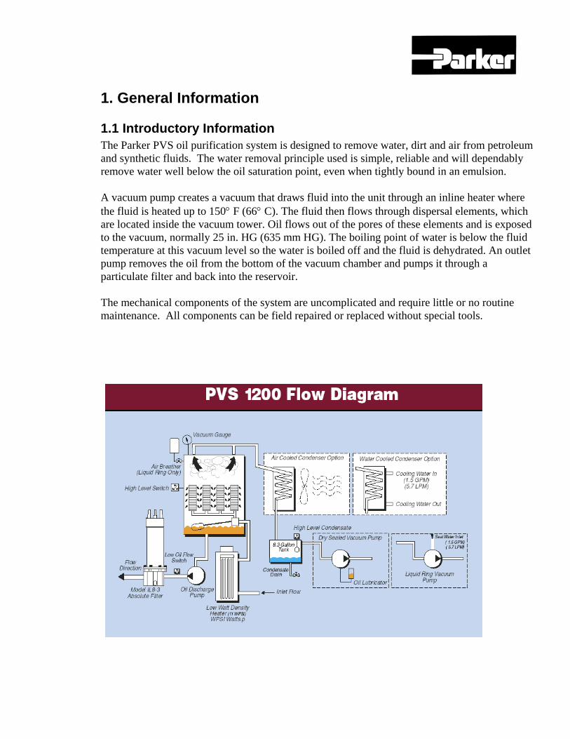
1.1 Introductory Information The Parker PVS oil purification system is designed to remove water, dirt and air from petroleum and synthetic fluids. The water removal principle used is simple, reliable and will dependably remove water well below the oil saturation point, even when tightly bound in an emulsion. A vacuum pump creates a vacuum that draws fluid into the unit through an inline heater where the fluid is heated up to 150° F (66° C). The fluid then flows through dispersal elements, which are located inside the vacuum tower. Oil flows out of the pores of these elements and is exposed to the vacuum, normally 25 in. HG (635 mm HG). The boiling point of water is below the fluid temperature at this vacuum level so the water is boiled off and the fluid is dehydrated. An outlet pump removes the oil from the bottom of the vacuum chamber and pumps it through a particulate filter and back into the reservoir. The mechanical components of the system are uncomplicated and require little or no routine maintenance. All components can be field repaired or replaced without special tools.
1.2 Precautions - Oil contaminated with hazardous materials If there is any possibility that the oil being purified contains a solvent or materials which could be considered hazardous, either with toxicant or flammable explosives, the purifier should not be used unless precautions are taken to vent the vapors in a safe manner according to local, state and federal codes. Of course, normal safety practices and common sense should be used at all times when operating this unit. This caution is necessary to prevent the possibility of fire, explosion, or toxic injury to persons and property. NOTE: THE PVS UNIT SHOULD NEVER BE USED TO REMOVE VOLITILES SUCH AS; DIESEL FUEL, GASOLINE OR OTHER PRODUCTS WITH LOW FLASH POINTS, EXPOLOSIVE IN NATURE OR TOXIC. FOR CLARIFICATION CONSULT YOUR FACTORY REPRESENTATIVE FOR DETAILED INFORMATION.
1.3 Fluid Compatibility The process fluid must be compatible with Viton™ seal material Viton™ is compatible for service with most petroleum-based oils. PVS Units may be ordered with EPR seals to provide compatibility with other fluids. Contact Parker Filter Division for special applications and pricing.
2.0 Installation and Startup Procedures 2.1 Unpacking The PVS dehydrator is shipped in a heavy cardboard shipping crate for maximum protection during shipment. Remove the top and sides of the crate to expose the PVS unit. Cut the shipping bands and use a forklift to raise the unit slightly. Use a forklift to lift the unit slightly, then slide the mounting skid away from the unit and lower the unit to the floor. Either roll it to the final location or use the forklift with the forks spread to wheel width. Note: The operational manuals are shipped with the unit and are located inside the electrical panel.
After the unit has been removed from it’s shipping crate it should be checked thoroughly for any damage that may have occurred during shipment. All damage attributed to the handling and shipping of the unit must be recorded and brought to the attention of the shipper immediately. This unit is insured for shipping related damage.
This unit has been thoroughly tested for a minimum of 8 hours (run time). Fluid used to test the unit is matched as closely as possible to that listed on the application sheet completed by the customer and supplied with the order. The unit has been thoroughly inspected for defects prior to shipment. However, all connections should be checked prior to operating this unit, vibration and/or rough handling during shipment could adversely effect component alignment and/or connection tightness.
2.2 Mechanical Installation With the PVS unit in place, connect the inlet and outlet hoses from the reservoir to the PVS unit. See the specification sheet in this manual for correct sizing and distance from the reservoir.
The inlet port has been sized to provide enough flow to operate the unit in the automatic mode using oil with a maximum viscosity of 1500 SSU (323 cSt). A hose diameter equal to inlet/outlet port size (see specification sheet) is required to provide adequate oil supply to this unit. Use of a smaller diameter line will restrict the flow, and will adversely effect the automatic operation of the unit.
The inlet and outlet connections have been sized for maximum hose lengths of 25 feet. Use of longer hose lengths must be approved by the factory prior to installation. Use of a “quick disconnect” on the inlet line is not recommended, they can restrict flow to the unit in specific applications.
Oil is drawn into the unit by vacuum created by the PVS unit and is capable of pulling in oil with up to 8-ft. (2.4 m) of negative head. For applications that exceed this please consult the factory. When placing the PVS unit below the reservoir by more than 4-ft. (1.2 m), a solenoid operated inlet shut-off valve is required. “If not installed the unit can overflow with oil when shut off”.
2.3 Electrical Installation 2.3.1 Electrical Power Supply Connection Attach a properly sized power cord to the unit. (Note: The PVS unit is not supplied from the factory with a power cord, as there are many different codes and preferences in different areas of the world). Size the cord for the load stated in the specification sheet found as part of this manual (See section, 3.0 Specification Sheet, of this manual for electrical specifications). The power leads should be connected to the labeled terminal points located in the electrical control panel. Note: It is important that the unit be grounded properly before operation. 2.3.2 Motor Rotation Electric motors are used to drive the outlet oil pump and the vacuum pump on this unit. These motors operate at the same time and in the same rotation. If the rotation of either motor is believed to be incorrect, both motors will be incorrect. Do not attempt to change rotation of one motor only. The unit has been tested for common rotation of these motors at the factory. Changes to the rotation of only one motor will result in damage to the system and will void the warranty. The PVS system is equipped with a “phase fail” electrical circuit that detects when the power supply is out of phase. When this condition exists the unit will not operate and a red light will illuminate on the control panel. To bring the unit into phase simply rotate the selector switch next to the light on the control panel to the opposite position, wait 5 seconds for the light to extinguish and the unit is ready for normal operation. 2.4 Vacuum Pump Pre-Start The vacuum pump used on the DS Model uses oil to lubricate the pump during operation. This oil is supplied from a reservoir located along side the vacuum pump. The oil reservoir must be maintained at a level shown on the side of the sight glass in order for the vacuum pump to operate to capacity. Prior to starting the unit it is important to inspect the vacuum pump reservoir for proper oil level. The recommended lubricant for this vacuum pump is Duratex 32. (The service bulletin from the vacuum pump manufacturer indicates the correct oil to be used. The oil reservoir used on the PVS unit holds one third of a quart (490-m/l) of oil, which typically lasts between 100-160 hours of continuous operation. Oil level should be checked daily. Hydraulic oil is not recommended and can cause damage to the vacuum pump if used.
2.5 Operating Instructions 1. Connect inlet and outlet hoses to supply oil reservoir. (Line size should be >1” diameter for
inlet and >1” for outlet, with a maximum of 25 feet in length) 2. Connect power supply cord to power source and activate power disconnect to “on” position. If
a red light illuminates labeled “phase failure”, rotate reversing switch to correct. 3. Open all inlet and outlet valves on the dehydrator and the oil supply reservoir. 4. Close all drain valves on the dehydrator. (Drain valves and connections are located at the
bottom of the outlet filter, condensate tank and a separate oil sample port valve on top of the outlet oil filter.
5. Press start button and hold until red “low flow” light is extinguished. (approximately 15-30
seconds) Be certain that the set point is reading on the heater controller is below 40°F before starting the unit. Damage can occur to the oil heaters if they are energized prior to oil filling the heater assemblies.
6. Energize the heater by pressing the “up arrow” located on the temperature controller.
Continue to press the “up arrow” until the desired temperature setting is reached. (140°F - 150°F) Note: The temperature controller has been programmed to prevent the heater setting to be raised manually above 180°F. Contact the factory for more instructions.
7. Observe the vacuum gauge pressure. Normal should be 25 “/hg, if not adjust pressure by
opening or closing the needle valve located just below the air breather near the top of the vacuum chamber. This adjustment is gradual and does not respond quickly, so there will be a 3-5 second delay in results when the adjustment is made.
8. Observe the liquid level gauge located at the bottom of the vacuum chamber. Visually check
the oil level while operating, it should normally run at about the half way mark in the gauge. (If the oil level is low this could mean the inlet oil line is too small or the dispersal elements located in the vacuum chamber are becoming dirty.) Note: When first starting the unit with cold oil it is common to see a “low level” in this sight glass. After the temperature has risen the oil level normally will rise to the half way mark.
9. To stop dehydrator, press “down “ arrow on heater controller to “OFF”, wait 10 – 15 minuets
and press stop button on control panel.
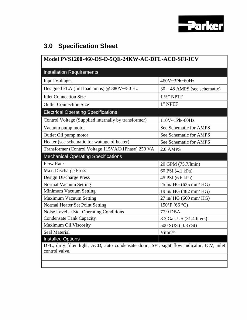
3.0 Specification Sheet Model PVS1200-460-DS-D-5QE-24KW-AC-DFL-ACD-SFI-ICV Installation Requirements
Input Voltage: 460V~3Ph~60Hz Designed FLA (full load amps) @ 380V~/50 Hz 30 – 48 AMPS (see schematic) Inlet Connection Size 1 ½” NPTF Outlet Connection Size 1” NPTF
Electrical Operating Specifications Control Voltage (Supplied internally by transformer) 110V~1Ph~60Hz Vacuum pump motor See Schematic for AMPS Outlet Oil pump motor See Schematic for AMPS Heater (see schematic for wattage of heater) See Schematic for AMPS Transformer (Control Voltage 115VAC/1Phase) 250 VA 2.0 AMPS Mechanical Operating Specifications Flow Rate 20 GPM (75.7/lmin) Max. Discharge Press 60 PSI (4.1 kPa) Design Discharge Press 45 PSI (6.6 kPa) Normal Vacuum Setting 25 in/ HG (635 mm/ HG) Minimum Vacuum Setting 19 in/ HG (482 mm/ HG) Maximum Vacuum Setting 27 in/ HG (660 mm/ HG) Normal Heater Set Point Setting 150°F (66 °C) Noise Level at Std. Operating Conditions 77.9 DBA Condensate Tank Capacity 8.3 Gal. US (31.4 liters) Maximum Oil Viscosity 500 SUS (108 cSt) Seal Material Viton™ Installed Options DFL, dirty filter light, ACD, auto condensate drain, SFI, sight flow indicator, ICV, inlet control valve.
4.0 Safety Instructions
The PVS unit has been examined for safety. The hazards have been identified and adequate protection provided when these instructions are followed.
4.1 Precautions - Oil contaminated with hazardous materials The PVS should not be used on liquids with a flash point below 200 °F (93 °C). If the possibility exists that the oil being purified is contaminated with a solvent, materials which could be considered hazardous, toxicant or flammable explosives, the purifier should not be used unless precautions are taken to vent the vapors in a safe manner according to local, state and federal codes. Of course, normal safety practices and common sense should be used at all times when operating this unit. This caution is necessary to prevent the possibility of fire, explosion, or toxic injury to persons and property.
4.2 Safety Labels
Danger High Voltage Turn Power Off Before Servicing The PVS unit has been manufactured to use 460V~3Ph~60Hz input electrical power. Supply power to the PVS unit should be disconnected before the electrical panel door is opened. Follow procedures for explosive environments.
Warning Electrical Hazard Authorized Personnel Only
460V~3Ph~60Hz is supplied to the PVS unit, only authorized and trained personnel should open the electrical cabinet to attempt service. Power disconnect on panel door should be off prior to opening the door. All electrical power to the unit should be terminated prior to opening the door.
CAUTION Hot Surface Do Not Touch The normal operating temperature for the PVS unit is 150°F (66°C). There are exposed areas of the heater housing which are hot to touch. While not normally hot enough to burn, it is uncomfortable and should be avoided.
5.0 Trouble Shooting
PROBLEM CAUSE
SOLUTION
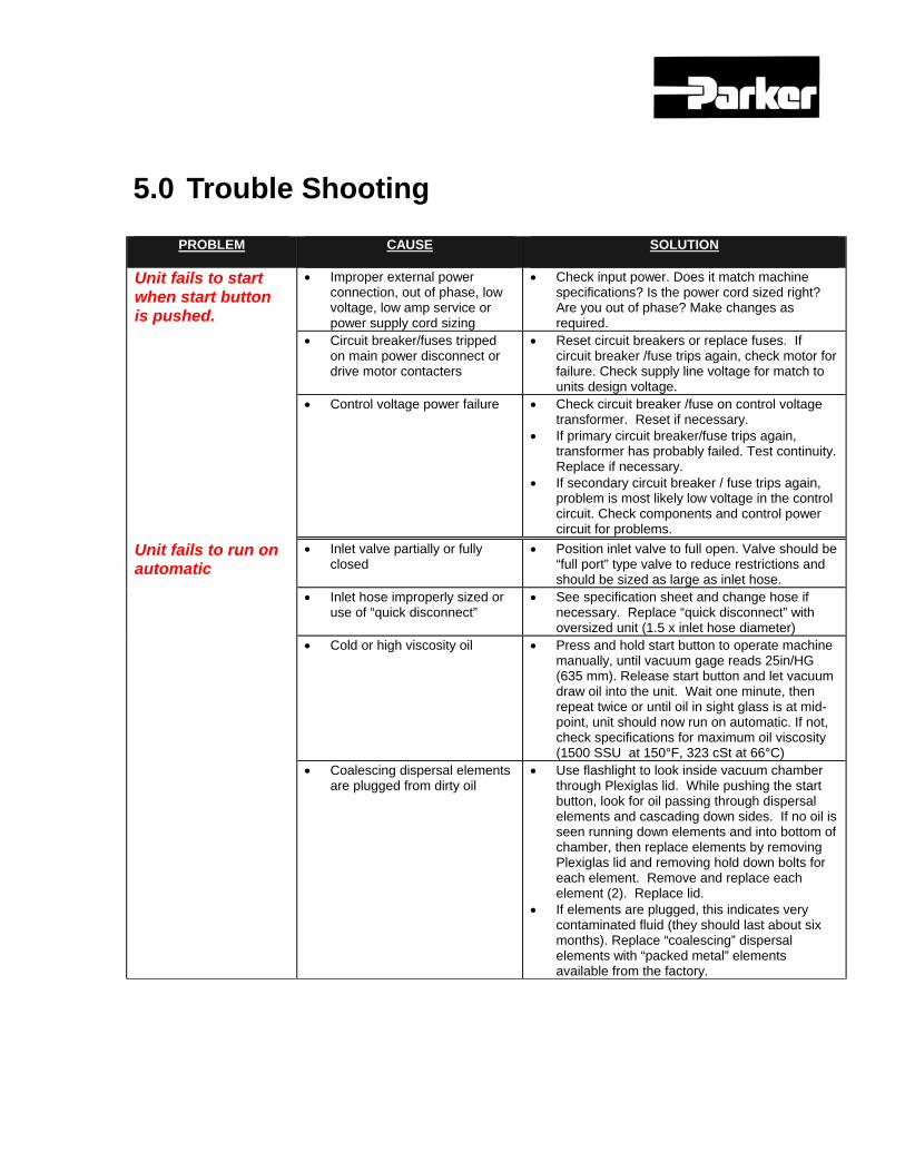
Unit fails to start when start button is pushed.
• Improper external power connection, out of phase, low voltage, low amp service or power supply cord sizing
• Check input power. Does it match machine specifications? Is the power cord sized right? Are you out of phase? Make changes as required.
• Circuit breaker/fuses tripped on main power disconnect or drive motor contacters
• Reset circuit breakers or replace fuses. If circuit breaker /fuse trips again, check motor for failure. Check supply line voltage for match to units design voltage.
• Control voltage power failure • Check circuit breaker /fuse on control voltage transformer. Reset if necessary.
• If primary circuit breaker/fuse trips again, transformer has probably failed. Test continuity. Replace if necessary.
• If secondary circuit breaker / fuse trips again, problem is most likely low voltage in the control circuit. Check components and control power circuit for problems.
Unit fails to run on automatic
• Inlet valve partially or fully closed
• Position inlet valve to full open. Valve should be “full port” type valve to reduce restrictions and should be sized as large as inlet hose.
• Inlet hose improperly sized or use of “quick disconnect”
• See specification sheet and change hose if necessary. Replace “quick disconnect” with oversized unit (1.5 x inlet hose diameter)
• Cold or high viscosity oil • Press and hold start button to operate machine manually, until vacuum gage reads 25in/HG (635 mm). Release start button and let vacuum draw oil into the unit. Wait one minute, then repeat twice or until oil in sight glass is at mid-point, unit should now run on automatic. If not, check specifications for maximum oil viscosity (1500 SSU at 150°F, 323 cSt at 66°C)
• Coalescing dispersal elements are plugged from dirty oil
• Use flashlight to look inside vacuum chamber through Plexiglas lid. While pushing the start button, look for oil passing through dispersal elements and cascading down sides. If no oil is seen running down elements and into bottom of chamber, then replace elements by removing Plexiglas lid and removing hold down bolts for each element. Remove and replace each element (2). Replace lid.
• If elements are plugged, this indicates very contaminated fluid (they should last about six months). Replace “coalescing” dispersal elements with “packed metal” elements available from the factory.
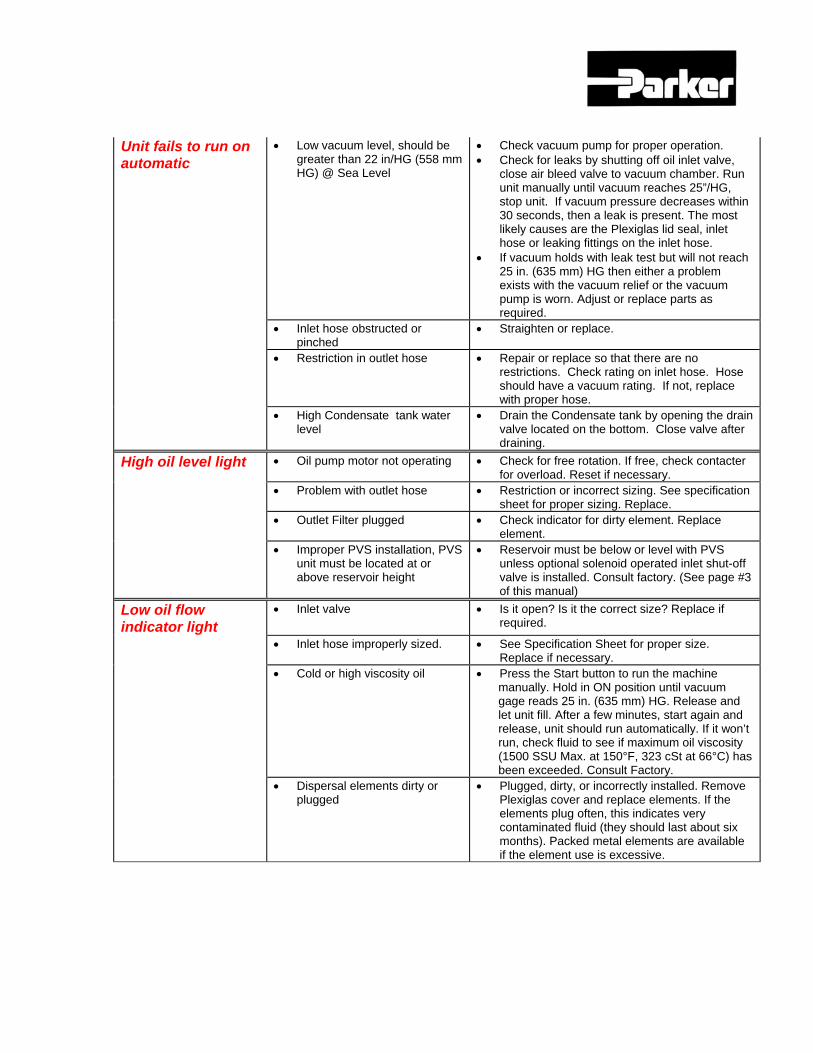
Unit fails to run on automatic
• Low vacuum level, should be greater than 22 in/HG (558 mm HG) @ Sea Level
• Check vacuum pump for proper operation. • Check for leaks by shutting off oil inlet valve,
close air bleed valve to vacuum chamber. Run unit manually until vacuum reaches 25”/HG, stop unit. If vacuum pressure decreases within 30 seconds, then a leak is present. The most likely causes are the Plexiglas lid seal, inlet hose or leaking fittings on the inlet hose.
• If vacuum holds with leak test but will not reach 25 in. (635 mm) HG then either a problem exists with the vacuum relief or the vacuum pump is worn. Adjust or replace parts as required.
• Inlet hose obstructed or pinched
• Straighten or replace.
• Restriction in outlet hose • Repair or replace so that there are no restrictions. Check rating on inlet hose. Hose should have a vacuum rating. If not, replace with proper hose.
• High Condensate tank water level
• Drain the Condensate tank by opening the drain valve located on the bottom. Close valve after draining.
High oil level light • Oil pump motor not operating • Check for free rotation. If free, check contacter for overload. Reset if necessary.
• Problem with outlet hose • Restriction or incorrect sizing. See specification sheet for proper sizing. Replace.
• Outlet Filter plugged • Check indicator for dirty element. Replace element.
• Improper PVS installation, PVS unit must be located at or above reservoir height
• Reservoir must be below or level with PVS unless optional solenoid operated inlet shut-off valve is installed. Consult factory. (See page #3 of this manual)
Low oil flow indicator light
• Inlet valve • Is it open? Is it the correct size? Replace if required.
• Inlet hose improperly sized. • See Specification Sheet for proper size. Replace if necessary.
• Cold or high viscosity oil • Press the Start button to run the machine manually. Hold in ON position until vacuum gage reads 25 in. (635 mm) HG. Release and let unit fill. After a few minutes, start again and release, unit should run automatically. If it won’t run, check fluid to see if maximum oil viscosity (1500 SSU Max. at 150°F, 323 cSt at 66°C) has been exceeded. Consult Factory.
• Dispersal elements dirty or plugged
• Plugged, dirty, or incorrectly installed. Remove Plexiglas cover and replace elements. If the elements plug often, this indicates very contaminated fluid (they should last about six months). Packed metal elements are available if the element use is excessive.
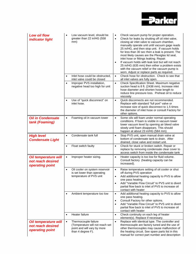
Low oil flow indicator light
• Low vacuum level, should be greater than 22 in/HG (558 mm)
• Check vacuum pump for proper operation. • Check for leaks by shutting off oil inlet valve,
closing air inlet valve to vacuum chamber, manually operate unit until vacuum gage reads 25 in/HG, and then stop unit. If vacuum holds for less than 30 sec then a leak is present. The most likely causes are the Plexiglas lid seal, inlet hose or fittings leaking. Repair.
• If vacuum holds with leak test but will not reach 25 in/HG (635 mm) then either a problem exists with the vacuum relief or the vacuum pump is worn. Adjust or replace parts as required.
• Inlet hose could be obstructed, inlet valve could be closed
• Check hose for obstruction. Check to see that all inlet valves are fully open.
• Improper PVS installation, negative head too high for unit
• Check Specification Sheet. Maximum negative suction head is 8 ft. (2438 mm). Increase inlet hose diameter and shorten hose length to reduce line pressure loss. Preheat oil to reduce viscosity
• Use of “quick disconnect” on inlet hose.
• Quick disconnects are not recommended. Replace with standard “full port” valve or increase size of quick disconnect to 1.5 times the diameter of inlet hose or consult Factory for other options.
Oil in Condensate tank (Foaming)
• Foaming oil in vacuum tower • Some oils will foam under normal operating conditions. If foam is visible in vacuum tower lower vacuum level by opening air bleed valve slowly until foam disappears. This should happen at about 23 in/HG (584 mm)
High level Condensate Light
• Condensate tank full • Stop PVS unit, open manual drain valve at bottom of condensate tank to drain. After drained, close valve and restart unit.
• Float switch faulty • Check for stuck or broken switch. Repair or replace by removing condensate clear cover to access switch from inside the condensate tank
Oil temperature will not reach desired operating point
• Improper heater sizing. • Heater capacity is too low for fluid volume. Consult factory (heating capacity can be increased).
• Oil cooler on system reservoir is set lower than operating temperature of PVS unit
• Raise temperature setting of oil cooler or shut off during PVS operation
• Add additional heating capacity to PVS to allow one pass heating.
• Add “Variable Flow Circuit” to PVS unit to divert partial flow back to inlet of PVS to increase oil contact with heater
• Ambient temperature too low • Add additional heating capacity to PVS to allow one pass heating.
• Consult Factory for other options. • Add “Variable Flow Circuit” to PVS unit to divert
partial flow back to inlet of PVS to increase oil contact with heater
• Heater failure • Check continuity on each leg of heater element(s). Replace if necessary.
Oil temperature will not reach desired operating point
• Thermocouple failure (Temperature will not reach set point and will vary by more than 4 degree F).
• Replace with identical type. The controller and thermocouple are factory tuned and the use of other thermocouples may cause malfunction of the heating circuit. See spare parts list in this manual for correct part number and description
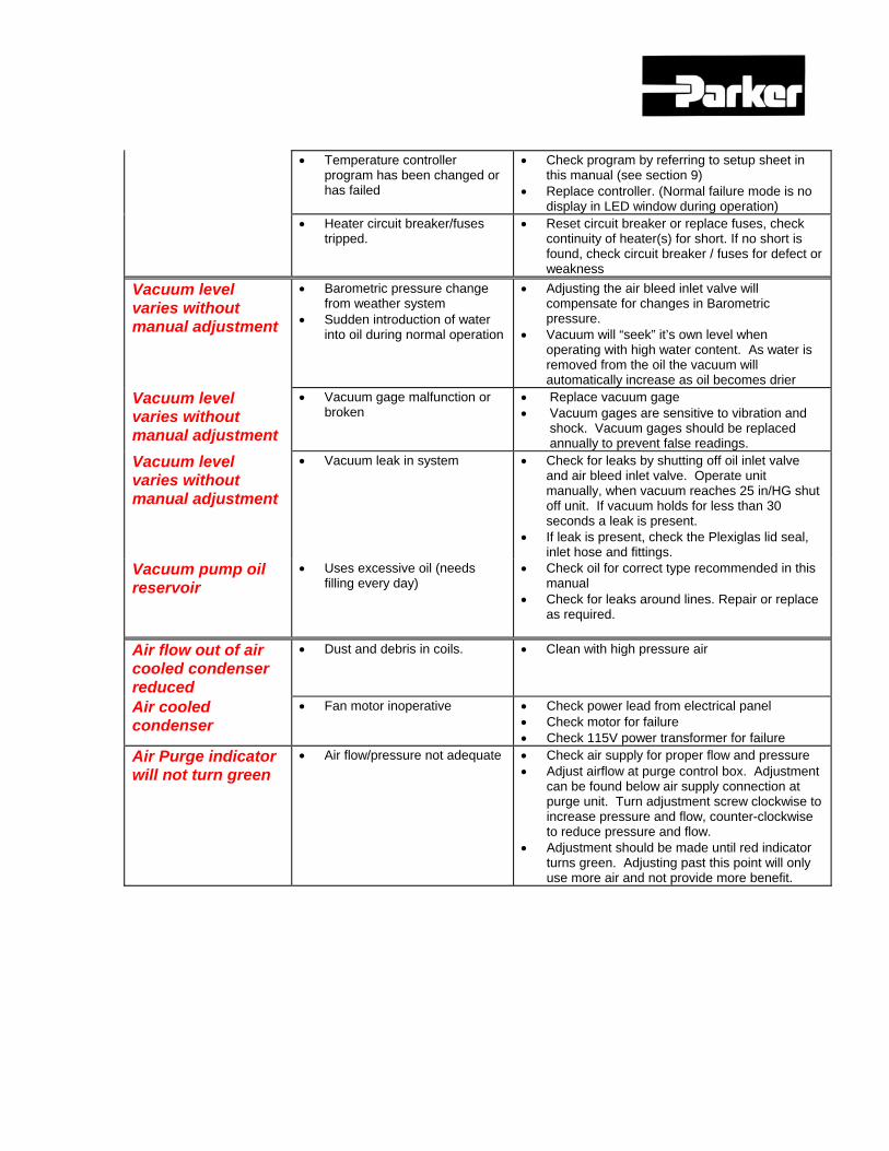
• Temperature controller
program has been changed or has failed
• Check program by referring to setup sheet in this manual (see section 9)
• Replace controller. (Normal failure mode is no display in LED window during operation)
• Heater circuit breaker/fuses tripped.
• Reset circuit breaker or replace fuses, check continuity of heater(s) for short. If no short is found, check circuit breaker / fuses for defect or weakness
Vacuum level varies without manual adjustment
• Barometric pressure change from weather system
• Sudden introduction of water into oil during normal operation
• Adjusting the air bleed inlet valve will compensate for changes in Barometric pressure.
• Vacuum will “seek” it’s own level when operating with high water content. As water is removed from the oil the vacuum will automatically increase as oil becomes drier
Vacuum level varies without manual adjustment
• Vacuum gage malfunction or broken
• Replace vacuum gage • Vacuum gages are sensitive to vibration and
shock. Vacuum gages should be replaced annually to prevent false readings.
Vacuum level varies without manual adjustment
• Vacuum leak in system • Check for leaks by shutting off oil inlet valve and air bleed inlet valve. Operate unit manually, when vacuum reaches 25 in/HG shut off unit. If vacuum holds for less than 30 seconds a leak is present.
• If leak is present, check the Plexiglas lid seal, inlet hose and fittings.
Vacuum pump oil reservoir
• Uses excessive oil (needs filling every day)
• Check oil for correct type recommended in this manual
• Check for leaks around lines. Repair or replace as required.
Air flow out of air cooled condenser reduced
• Dust and debris in coils. • Clean with high pressure air
Air cooled condenser
• Fan motor inoperative • Check power lead from electrical panel • Check motor for failure • Check 115V power transformer for failure
Air Purge indicator will not turn green
• Air flow/pressure not adequate • Check air supply for proper flow and pressure • Adjust airflow at purge control box. Adjustment
can be found below air supply connection at purge unit. Turn adjustment screw clockwise to increase pressure and flow, counter-clockwise to reduce pressure and flow.
• Adjustment should be made until red indicator turns green. Adjusting past this point will only use more air and not provide more benefit.
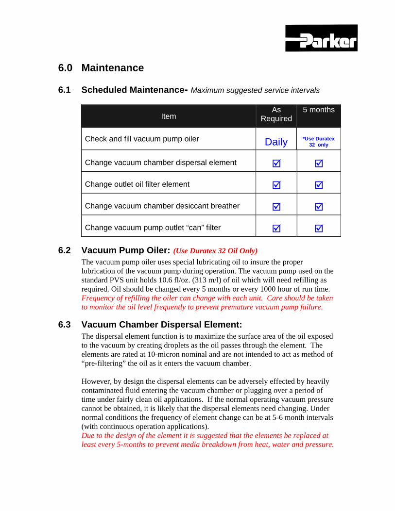
6.0 Maintenance
6.1 Scheduled Maintenance- Maximum suggested service intervals
Item As
Required 5 months
Check and fill vacuum pump oiler Daily *Use Duratex 32 only
Change vacuum chamber dispersal element
Change outlet oil filter element
Change vacuum chamber desiccant breather
Change vacuum pump outlet “can” filter
6.2 Vacuum Pump Oiler: (Use Duratex 32 Oil Only) The vacuum pump oiler uses special lubricating oil to insure the proper lubrication of the vacuum pump during operation. The vacuum pump used on the standard PVS unit holds 10.6 fl/oz. (313 m/l) of oil which will need refilling as required. Oil should be changed every 5 months or every 1000 hour of run time. Frequency of refilling the oiler can change with each unit. Care should be taken to monitor the oil level frequently to prevent premature vacuum pump failure.
6.3 Vacuum Chamber Dispersal Element: The dispersal element function is to maximize the surface area of the oil exposed to the vacuum by creating droplets as the oil passes through the element. The elements are rated at 10-micron nominal and are not intended to act as method of “pre-filtering” the oil as it enters the vacuum chamber. However, by design the dispersal elements can be adversely effected by heavily contaminated fluid entering the vacuum chamber or plugging over a period of time under fairly clean oil applications. If the normal operating vacuum pressure cannot be obtained, it is likely that the dispersal elements need changing. Under normal conditions the frequency of element change can be at 5-6 month intervals (with continuous operation applications). Due to the design of the element it is suggested that the elements be replaced at least every 5-months to prevent media breakdown from heat, water and pressure.
6.4 Outlet Oil Filter Element:
The outlet oil filter is equipped with a differential pressure indicator to alert the user when the element is ready to be changed. This indicator is set approximately 3 PSI lower than the bypass valve in the filter assembly to give the user time to shut the unit down prior to the filter entering a “bypass” state. If the element is not changed at indication the unit will continue to operate but the filter will be in “bypass”. Element change frequency can and will vary with every application and cannot be predicted very effectively. However, the filter has been oversized by approximately 6 times rated flow to maximize the life of the element under normal operating conditions. It is suggested that the element be changed every 5 or6 -months even if no indication is shown during that time. The filter media can become fatigued and fail due to flow surges, heat, water and pressure after continuous operation over a long period of time.
6.5 Vacuum Chamber Desiccant Breather Element: Metered outside air is used to control the vacuum pressure inside the vacuum chamber. This air passes through a desiccant breather to remove particulate and moisture from the air as it enters the vacuum chamber. The element can be plugged within a very short period of time if a large amount of moisture or air-borne contamination is present during operation. Under normal operating conditions and continuous operation, the air breather element will last approximately 3 months. It is suggested that the breather be changed at least every 5 months.
6.6 Vacuum Pump Maintenance
See separate operating manual for the vacuum pump.
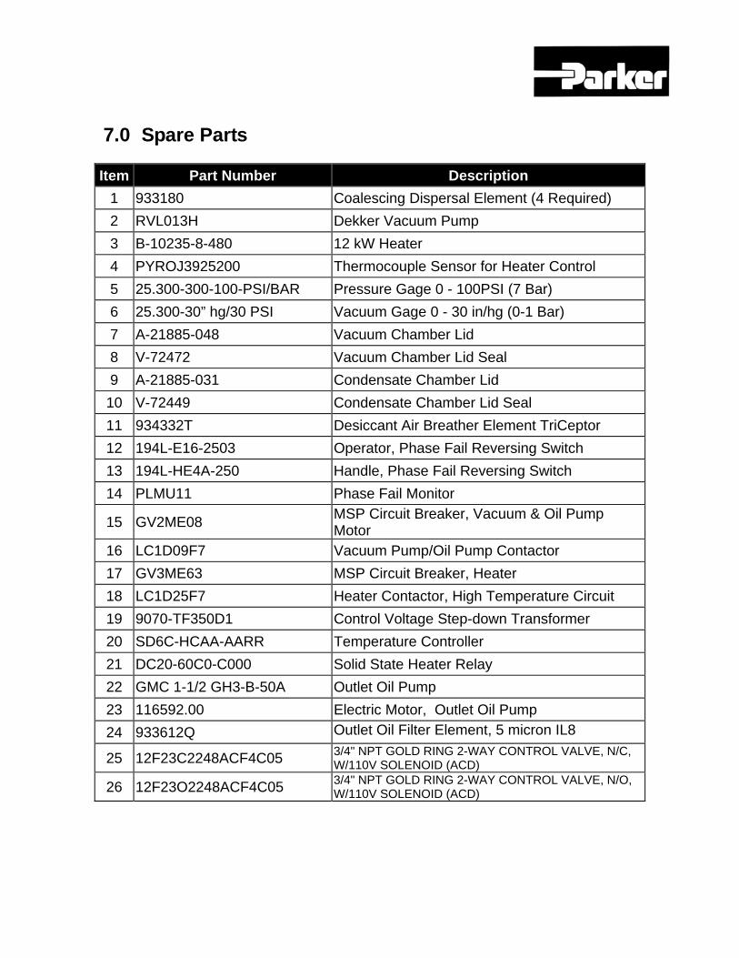
7.0 Spare Parts
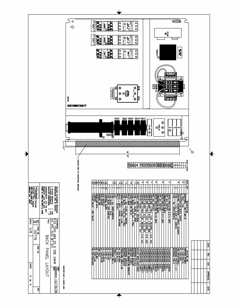
Item Part Number Description 1 933180 Coalescing Dispersal Element (4 Required) 2 RVL013H Dekker Vacuum Pump 3 B-10235-8-480 12 kW Heater 4 PYROJ3925200 Thermocouple Sensor for Heater Control 5 25.300-300-100-PSI/BAR Pressure Gage 0 - 100PSI (7 Bar) 6 25.300-30” hg/30 PSI Vacuum Gage 0 - 30 in/hg (0-1 Bar) 7 A-21885-048 Vacuum Chamber Lid 8 V-72472 Vacuum Chamber Lid Seal 9 A-21885-031 Condensate Chamber Lid 10 V-72449 Condensate Chamber Lid Seal 11 934332T Desiccant Air Breather Element TriCeptor 12 194L-E16-2503 Operator, Phase Fail Reversing Switch 13 194L-HE4A-250 Handle, Phase Fail Reversing Switch 14 PLMU11 Phase Fail Monitor
15 GV2ME08 MSP Circuit Breaker, Vacuum & Oil Pump Motor
16 LC1D09F7 Vacuum Pump/Oil Pump Contactor 17 GV3ME63 MSP Circuit Breaker, Heater 18 LC1D25F7 Heater Contactor, High Temperature Circuit 19 9070-TF350D1 Control Voltage Step-down Transformer 20 SD6C-HCAA-AARR Temperature Controller 21 DC20-60C0-C000 Solid State Heater Relay 22 GMC 1-1/2 GH3-B-50A Outlet Oil Pump 23 116592.00 Electric Motor, Outlet Oil Pump 24 933612Q Outlet Oil Filter Element, 5 micron IL8
25 12F23C2248ACF4C05 3/4" NPT GOLD RING 2-WAY CONTROL VALVE, N/C, W/110V SOLENOID (ACD)
26 12F23O2248ACF4C05 3/4" NPT GOLD RING 2-WAY CONTROL VALVE, N/O, W/110V SOLENOID (ACD)

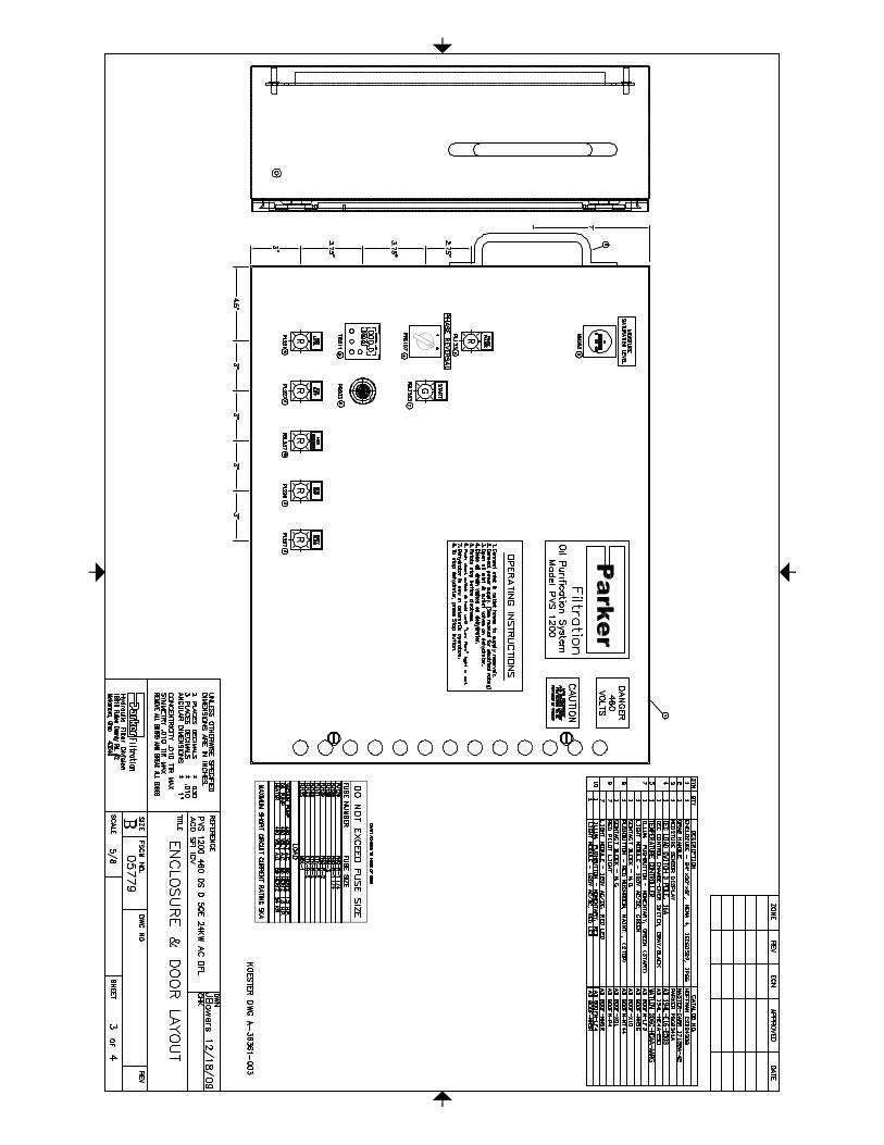
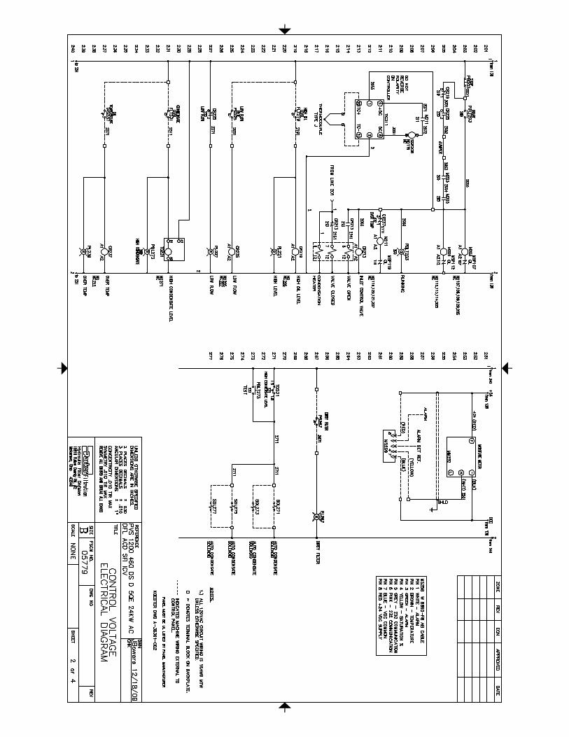
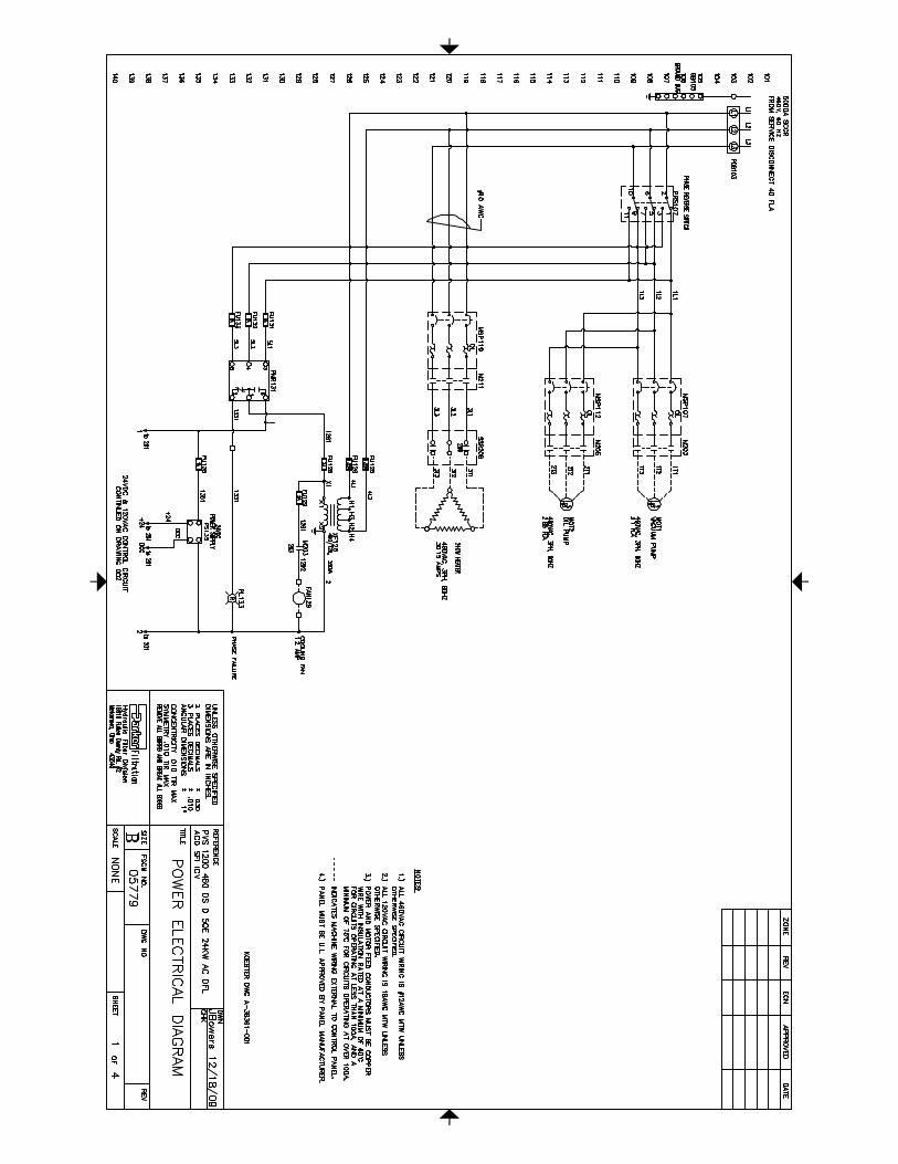
8.0 Electrical Drawings
The electrical prints for this PVS unit are located in this section.

9.0 Unit Test Report
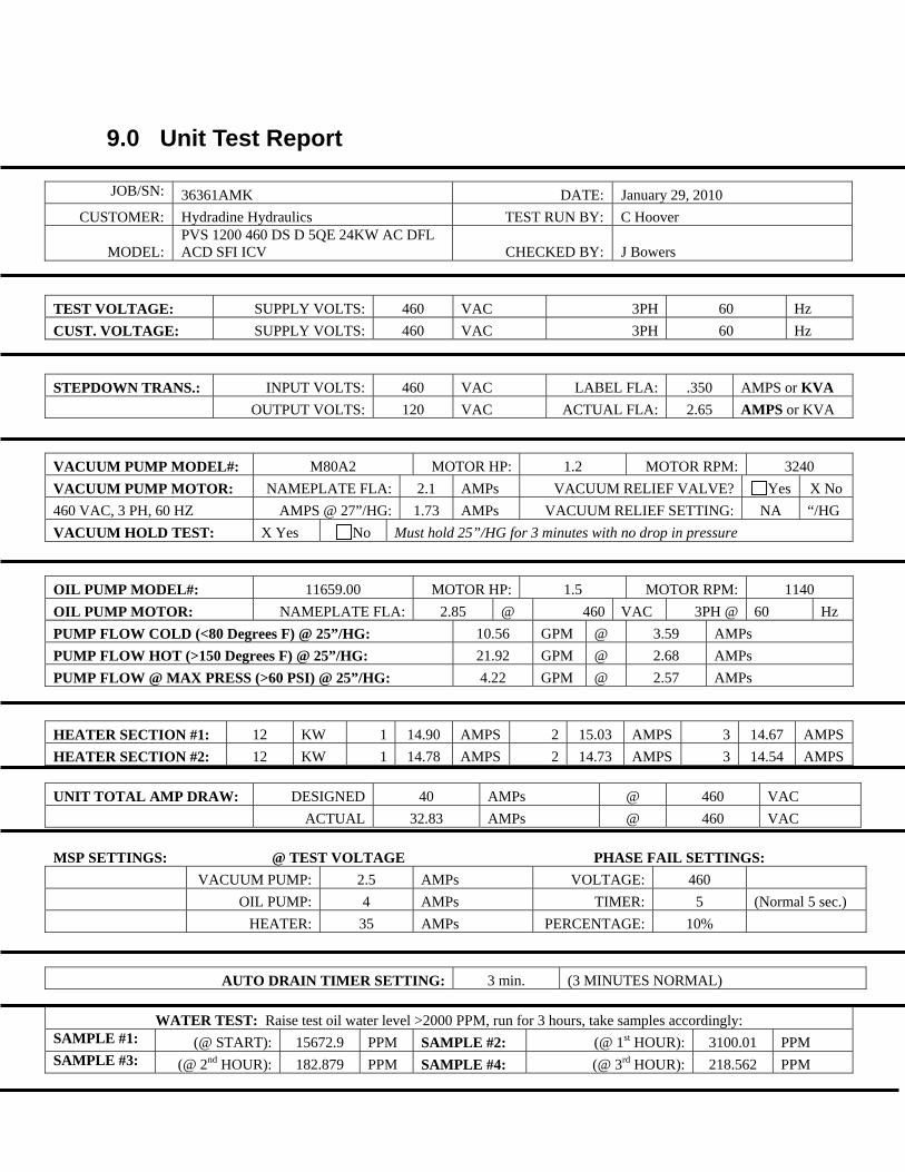
9.0 Unit Test Report
JOB/SN: 36361AMK DATE: January 29, 2010 CUSTOMER: Hydradine Hydraulics TEST RUN BY: C Hoover
MODEL: PVS 1200 460 DS D 5QE 24KW AC DFL ACD SFI ICV CHECKED BY: J Bowers
TEST VOLTAGE: SUPPLY VOLTS: 460 VAC 3PH 60 Hz CUST. VOLTAGE: SUPPLY VOLTS: 460 VAC 3PH 60 Hz STEPDOWN TRANS.: INPUT VOLTS: 460 VAC LABEL FLA: .350 AMPS or KVA OUTPUT VOLTS: 120 VAC ACTUAL FLA: 2.65 AMPS or KVA VACUUM PUMP MODEL#: M80A2 MOTOR HP: 1.2 MOTOR RPM: 3240 VACUUM PUMP MOTOR: NAMEPLATE FLA: 2.1 AMPs VACUUM RELIEF VALVE? Yes X No 460 VAC, 3 PH, 60 HZ AMPS @ 27”/HG: 1.73 AMPs VACUUM RELIEF SETTING: NA “/HG VACUUM HOLD TEST: X Yes No Must hold 25”/HG for 3 minutes with no drop in pressure OIL PUMP MODEL#: 11659.00 MOTOR HP: 1.5 MOTOR RPM: 1140 OIL PUMP MOTOR: NAMEPLATE FLA: 2.85 @ 460 VAC 3PH @ 60 Hz PUMP FLOW COLD (<80 Degrees F) @ 25”/HG: 10.56 GPM @ 3.59 AMPs PUMP FLOW HOT (>150 Degrees F) @ 25”/HG: 21.92 GPM @ 2.68 AMPs PUMP FLOW @ MAX PRESS (>60 PSI) @ 25”/HG: 4.22 GPM @ 2.57 AMPs HEATER SECTION #1: 12 KW 1 14.90 AMPS 2 15.03 AMPS 3 14.67 AMPS HEATER SECTION #2: 12 KW 1 14.78 AMPS 2 14.73 AMPS 3 14.54 AMPS UNIT TOTAL AMP DRAW: DESIGNED 40 AMPs @ 460 VAC ACTUAL 32.83 AMPs @ 460 VAC MSP SETTINGS: @ TEST VOLTAGE PHASE FAIL SETTINGS: VACUUM PUMP: 2.5 AMPs VOLTAGE: 460 OIL PUMP: 4 AMPs TIMER: 5 (Normal 5 sec.) HEATER: 35 AMPs PERCENTAGE: 10%
AUTO DRAIN TIMER SETTING: 3 min. (3 MINUTES NORMAL)
WATER TEST: Raise test oil water level >2000 PPM, run for 3 hours, take samples accordingly: SAMPLE #1: (@ START): 15672.9 PPM SAMPLE #2: (@ 1st HOUR): 3100.01 PPM SAMPLE #3: (@ 2nd HOUR): 182.879 PPM SAMPLE #4: (@ 3rd HOUR): 218.562 PPM
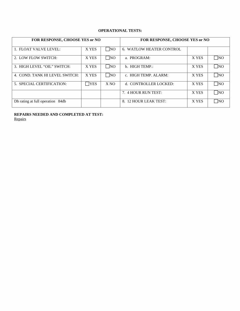
OPERATIONAL TESTS:
FOR RESPONSE, CHOOSE YES or NO FOR RESPONSE, CHOOSE YES or NO
1. FLOAT VALVE LEVEL: X YES NO 6. WATLOW HEATER CONTROL
2. LOW FLOW SWITCH: X YES NO a. PROGRAM: X YES NO
3. HIGH LEVEL “OIL” SWITCH: X YES NO b. HIGH TEMP.: X YES NO
4. COND. TANK HI LEVEL SWITCH: X YES NO c. HIGH TEMP. ALARM: X YES NO
5. SPECIAL CERTIFICATION: YES X NO d. CONTROLLER LOCKED: X YES NO
7. 4 HOUR RUN TEST: X YES NO
Db rating at full operation 84db 8. 12 HOUR LEAK TEST: X YES NO
REPAIRS NEEDED AND COMPLETED AT TEST: Repairs
10.0 Warranty
The items described in this document are hereby offered for sale at prices to be established by Parker Hannifin Corporation, its subsidiaries and its authorized distributors. This offer and its acceptance by any customer (“Buyer”) shall be governed by all of the following Terms and Conditions. Buyer’s order for any item described in its document, when communicated to Parker Hannifin Corporation, its subsidiary or an authorized distributor (“Seller”) verbally or in writing, shall constitute acceptance of this offer.
1. Terms and Conditions of Sale: All descriptions, quotations, proposals, offers, acknowledgments, acceptances and sales of Seller’s products are subject to and shall be governed exclusively by the terms and conditions stated herein. Buyer’s acceptance of any offer to sell is limited to these terms and conditions. Any terms or conditions in addition to, or inconsistent with those stated herein, proposed by Buyer in any acceptance of an offer by Seller, are hereby objected to. No such additional, different or inconsistent terms and conditions shall become part of the contract between Buyer and Seller unless expressly accepted in writing by Seller. Seller’s acceptance of any offer to purchase by Buyer is expressly conditional upon Buyer’s assent to all the terms and conditions stated herein, including any terms in addition to, or inconsistent with those contained in Buyer’s offer. Acceptance of Seller’s products shall in all events constitute such assent.
2. Payment: Payment shall be made by Buyer net 30 days from the date of delivery of the items purchased hereunder. Any claims by Buyer for omissions or shortages in a shipment shall be waived unless Seller receives notice thereof within 30 days after Buyer’s receipt of the shipment.
3. Delivery: Unless otherwise provided on the face hereof, delivery shall be made F.O.B. Seller’s plant. Regardless of the method of delivery, however, risk of loss shall pass to Buyer upon Seller’s delivery to a carrier. Any delivery dates shown are approximate only and Seller shall have no liability for any delays in delivery.
4. Warranty: Seller warrants that the item sold hereunder shall be free from defects in material or workmanship for a period of 547 days from the date of shipment to Buyer, or 3,000 hours of use, whichever expires first. THIS WARRANTY COMPRISES THE SOLE AND ENTIRE WARRANTY PERTAINING TO ITEMS PROVIDED HEREUNDER. SELLER MAKES NO OTHER WARRANTY, GUARANTEE, OR REPRESENTATION OF ANY KIND WHATSOEVER. ALL OTHER WARRANTIES, INCLUDING BUT NOT LIMITED TO, MERCHANTABILITY AND FITNESS FOR PURPOSE, WHETHER EXPRESS, IMPLIED, OR ARISING BY OPERATION OF LAW, TRADE USAGE, OR COURSE OF DEALING ARE HEREBY DISCLAIMED.
NOTWITHSTANDING THE FOREGOING, THERE ARE NO WARRANTIES WHATSOEVER ON ITEMS BUILT OR ACQUIRED WHOLLY OR PARTIALLY, TO BUYERS DESIGNS OR SPECIFICATIONS.
5. Limitation of Remedy: SELLER’S LIABILITY ARISING FROM OR IN ANY WAY CONNECTED WITH THE ITEMS SOLD OR THIS CONTRACT SHALL BE LIMITED EXCLUSIVELY TO REPAIR OR REPLACEMENT OF THE ITEMS SOLD OR REFUND OF THE PURCHASE PRICE PAID BY BUYER, AT SELLER’S SOLE OPTION IN NO EVENT SHALL SELLER BE LIABLE FOR ANY INCIDENTAL OR SEQUENTIAL OR SPECIAL DAMAGES OF ANY KIND OR NATURE WHATSOEVER, INCLUDING BUT NOT LIMITED TO LOST PROFITS ARISING FROM OR IN ANY WAY CONNECTED WITH THIS AGREEMENT OR ITEM SOLD HEREUNDER, WHETHER ALLEGED TO ARISE FROM BREACH OF CONTRACT, EXPRESS OR IMPLIED WARRANTY, OR IN TORT, INCLUDING WITHOUT LIMITATION, NEGLIGENCE, FAILURE TO WARN OR STRICT LIABILITY.
6. Changes, Reschedules and Cancellations: Buyer may request to modify the designs or specifications for the items sold hereunder as well as the quantities and delivery dates thereof, or may request to cancel all or part of this order, however, no such requested modification or cancellation shall become part of the contract between Buyer and Seller unless accepted by Seller in a written amendment to this Agreement. Acceptance of any such requested modification or cancellation shall be at Seller’s discretion, and shall be upon such terms and conditions as Seller may require.
7. Special Tooling: A tooling charge may be imposed for any special tooling, including without limitation, dies, fixtures, molds and patterns, acquired to manufacture items sold pursuant to this contract. Such special tooling shall be and remain Seller’s property notwithstanding payment of any charges by Buyer. In no event
will Buyer acquire any interest in apparatus belonging to Seller which is utilized in the manufacture of the items sold hereunder, even if such apparatus has been specially converted or adapted for such manufacture and notwithstanding any charges paid by Buyer. Unless otherwise agreed, Seller shall have the right to alter, discard or otherwise dispose of any special tooling or other property in its sole discretion at any time.
8. Buyer’s Property: Any designs, tools, patterns, materials, drawings, confidential information or equipment furnished by Buyer or any other items which become Buyer’s property, may be considered obsolete and may be destroyed by Seller after two (2) consecutive years have elapsed without Buyer placing an order for the items which are manufactured using such property. Seller shall not be responsible for any loss or damage to such property while it is in Seller’s possession or control.
9. Taxes: Unless otherwise indicated on the face hereof, all prices and charges are exclusive of excise, sales, use, property, occupational or like taxes which may be imposed by any taxing authority upon the manufacture, sale or delivery of the items sold hereunder. If any such taxes must be paid by Seller or if Seller is liable for the collection of such tax, the amount thereof shall be in addition to the amounts for the items sold. Buyer agrees to pay all such taxes or to reimburse Seller therefore upon receipt of its invoice. If Buyer claims exemption from any sales, use or other tax imposed by any taxing authority, Buyer shall save Seller harmless from and against any such tax, together with any interest or penalties thereon which may be assessed if the items are held to be taxable.
10. Indemnity For Infringement of Intellectual Property Rights: Seller shall have no liability for infringement of any patents, trademarks, copyrights, trade dress, trade secrets or similar rights except as provided in this Part 10. Seller will defend and indemnify Buyer against allegations of infringement of U.S. patents, U.S. trademarks, copyrights, trade dress and trade secrets (hereinafter ‘Intellectual Property Rights’). Seller will defend at its expense and will pay the cost of any settlement or damages awarded in an action brought against Buyer based on an allegation that an item sold pursuant to this contract infringes the Intellectual Property Rights of a third party. Seller’s obligation to defend and indemnify Buyer is contingent on Buyer notifying Seller within ten (10) days after Buyer becomes aware of such allegations of infringement, and Seller having sole control over the defense of any allegations or actions including all negotiations for settlement or compromise. If an item sold hereunder is subject to a claim that it infringes the Intellectual Property Rights of a third party, Seller may, at its sole expense and option, procure for Buyer the right to continue using said item, replace or modify said time so as to make it noninfringing, or offer to accept return of said item and return the purchase price less a reasonable allowance for depreciation. Notwithstanding the foregoing Seller shall have no liability for claims of infringement based on information provided by Buyer, or directed to items delivered hereunder for which the designs are specified in whole or part by Buyer, or infringements resulting from the modification, combination or use in a system of any item sold hereunder. The foregoing provisions of this Part 10 shall constitute Seller’s sole and exclusive liability and Buyer’s sole and exclusive remedy for infringement of Intellectual Property Rights.
If a claim is based on information provided by Buyer or if the design for an item delivered hereunder is specified in whole or in part by Buyer, Buyer shall defend and indemnify Seller for all costs, expenses or judgments resulting from any claim that such item infringes any patent, trademark, copyright, trade dress, trade secret or any similar right.
11. Force Majeure: Seller does not assume the risk of and shall not be liable for delay or failure to perform any of Seller’s obligations by reason of circumstances beyond the reasonable control of Seller (hereinafter ‘Events of Force Majeure’). Events of Force Majeure shall include without limitation, accidents, acts of God, strikes or labor disputes, acts, laws, rules or regulations of any government or government agency, fires, floods, delays or failures in delivery of carriers or suppliers, shortages of materials and any other cause beyond Seller’s control.
12. Entire Agreement/Governing Law: The terms and conditions set forth herein, together with any amendments, modifications and any different terms or conditions expressly accepted by Seller in writing, shall constitute the entire Agreement concerning the items sold, and there are no oral or other representations or agreements which pertain thereto. This Agreement shall be governed in all respects by the law of the State of Ohio. No actions arising out of the sale of the items sold hereunder or this Agreement may be brought by either party more than two (2) years after the cause of action accrues.
Top Related