


Languages
Pages
Legal

IJRET: International Journal of Research in Engineering and Technology eISSN: 2319-1163 | pISSN: 2321-7308
_______________________________________________________________________________________
Volume: 02 Issue: 11 | Nov-2013, Available @ http://www.ijret.org 322
OPERATING AND EMISSION CHARACTERSTICS OF A NOVEL
DESIGN FOUR CHAMBERS INFECTIOUS MEAT INCINERATOR
Hamdi A. Abdel Salam
Department of Mechanical Power Engineering, Mansoura University, Mansoura, Egypt 33516
Email: [email protected]; Tel: +2-012-22181181; Fax: +2-050-2248585
Abstract
This paper investigates the operation and emission characteristics of a novel design four chambers infectious meat incinerator. This incinerator is internally divided into primary, secondary, intermediate and heat exchanger chambers. In the primary chamber, the infectious meat is burned using 95–200 kW burner, the combustion products are then passed through the intermediate chamber, the secondary chamber, and eventually through the heat exchanger chamber. A 50 kW burner is installed in the secondary chamber to complete the combustion of CO and to destruct the dioxin. Fresh air is then introduced to the flue gases to dilute the emission concentrations and to reduce the flue gas temperature. The flue gas is finally cleaned using an activated coke filter which is installed before the incinerator stack. The incinerator has been field tested at varied charging capacities of infectious meat, varied air to fuel ratios, and different combustion chamber temperatures. The emission concentration of particulate matter (P.M.), carbon monoxide (CO), sulfur dioxide (SO2), nitrogen oxides (NOx,), heavy metals, and dioxin have been measured at the maximum charging capacity of the incinerator. As a result of this work, it is proved that this incinerator offers an accepted and permanent solution to waste pollution problems that caused by infectious meat. The measured emissions of this incinerator highly comply with the maximum permitted emission limits of the environmental law. The heat exchanger reduced the flue gas temperature to 160°C and increased the economic viability of the incinerator; about 50% of the fuel cost has been recovered by using the hot water in the slaughterhouse. Index Terms: Incineration, Slaughterhouse incinerators, Emission control by incineration.
--------------------------------------------------------------------***------------------------------- ---------------------------------------
1. INTRODUCTION
Disposal of infectious meat in large animals’ slaughterhouses represents a serious environmental pollution problem all over the world. Incineration is the only of the waste treatment methods in use that simultaneously ensures maximum destruction of the organic materials in the infectious meat, produce inert residual products of reduced volume which can safely be dumped in landfills, allows recovery of the generated energy, and causes no long-term pollution problems. The term “incineration” (i.e. direct combustion of waste) is the term generally used (rather than thermal treatment of waste) in the literature on human health effects, usually without specifying precisely what actual technology or process is in use [1]. Incineration is also an air pollution control process in which objectionable organic matter (solid or vapor) is converted to harmless carbon dioxide and water vapor [2]. Incineration produces a host of high-temperature that destroys liquid and gaseous wastes containing organic compounds and slats, or eliminates the odors or toxicity associated with such streams. This process is widely used in the petroleum refining, gas processing, petrochemical, chemicals and pharmaceutical industries. To ensure the success of this process, proper air pollution control is a must [3]. Incinerators may be divided into three categories as: (i) municipal waste incinerators, (ii) hospital waste
incinerators, and (iii) slaughterhouse incinerators. Also incinerators can be regarded as: (i) direct flame incinerators and (ii) catalytic-type incinerators. In direct flame incinerators which is under investigation in this study, the organic matter is destroyed under the proper conditions and temperatures in the presence of the flame. Incineration of waste requires high temperatures (i.e. 850°C to 1200°C) which can produce airborne stack emissions and ash as its final outputs [1]. The actual temperature required to do an effective job depends on the specific contaminants involved, and the design of the combustion chamber [4]. By optimizing the combustion process control and using an advanced flue-gas cleaning system, emissions from municipal waste incineration plants can be kept very low, for many pollutants below verifiable limits [5-10]. These incinerators offer a reliable and cost-effective approach, particularly in case where the heat value of the waste is sufficient and oxidizer can be operated without supplemental fuel. While, if the heat value is not sufficient, the needed destruction temperatures can be sustained by an auxiliary fuel such as gas or fuel oil [6]. In slaughterhouse incinerators, in which infectious meat is disposed of with combustion process control, fuel consumption can be highly economic, and pollutants in the flue gas can be kept very low. This may be attributed to the high heat value of meat. In medical waste incinerators, due to the hazardous characteristics of the waste, highly
IJRET: International Journal of Research in Engineering and Technology eISSN: 2319-1163 | pISSN: 2321-7308
_______________________________________________________________________________________
Volume: 02 Issue: 11 | Nov-2013, Available @ http://www.ijret.org 323
hazardous pollutants are produced. The major pollutants of concern from medical waste incinerators and the ways to control air pollutants from waste incinerators have been identified in several investigations [6-17]. Pollution control methods in incinerators are basically categorized into wet scrubbers, dry scrubbers and fabric filters [7]. In Germany, especially the emission levels for dioxins and heavy metals are limited by legislation; flue gas cleaning with activated coke represented a well-proven technology for complying with these emission levels [18]. Infectious meat is collected in many municipalities with municipal waste and is disposed of in landfills or in municipal waste incinerators. In the cases where there are no landfills or municipal waste incinerators, the infectious meat is dumped in uncontrolled dumps causing a serious environmental problem, and then the need for an infectious meat incineration is a must. This paper presents the operating and emission characteristics of a novel design four chambers infectious meat incinerator. For this purpose, an incinerator has been designed, manufactured, erected and field tested. 2. INCINERATOR DESIGN, ERECTION AND FIELD TEST OPERATION
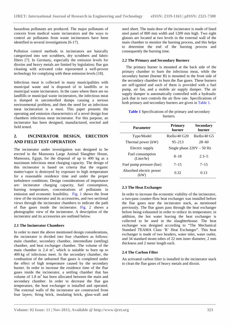
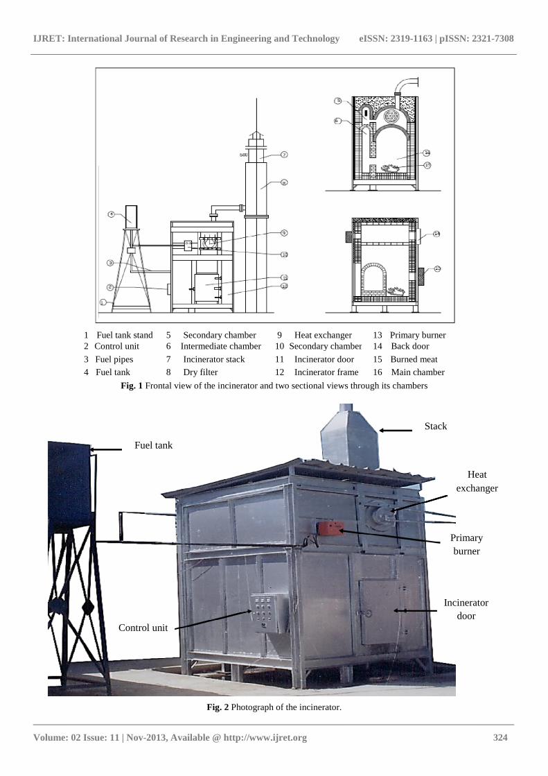
The incinerator under investigation was designed to be erected in the Mansoura Large Animal Slaughter House, Mansoura, Egypt, for the disposal of up to 400 kg as a maximum infectious meat charging capacity. The design of this incinerator is based on criteria that the organic matter/vapor is destroyed by exposure to high temperature for a reasonable residence time and under the proper turbulence conditions. Design considerations of importance are: incinerator charging capacity, fuel consumption, burning temperature, concentrations of pollutants in emission and economic feasibility. Fig. 1 shows the front view of the incinerator and its accessories, and two sectional views through the incinerator chambers to indicate the path of flue gases inside the incinerator. Fig. 2 shows a photographic view of the incinerator. A description of the incinerator and its accessories are outlined below.
2.1 The Incinerator Chambers
In order to meet the above mentioned design considerations, the incinerator is divided into four chambers as follows: main chamber, secondary chamber, intermediate (settling) chamber, and heat exchanger chamber. The volume of the main chamber is 2.4 m3, which is suitable to burn up to 400 kg of infectious meet. In the secondary chamber, the combustion of the unburned flue gases is completed under the effect of high temperature caused by the secondary burner. In order to increase the residence time of the flue gases inside the incinerator, a settling chamber that has volume of 1.8 m3 has been allocated between the main and secondary chamber. In order to decrease the flue gas temperature, the heat exchanger is installed and operated. The external walls of the incinerator are constructed from four layers; firing brick, insulating brick, glass-wall and
steel sheet. The main door of the incinerator is made of lined steel panel of 800 mm width and 1200 mm high. Two sight glasses are located at two levels in the external wall of the main chamber to monitor the burning process, and this helps to determine the end of the burning process and consequently the burning time.
2.2 The Primary and Secondary Burners
The primary burner is mounted at the back side of the primary chamber to burn the infectious meat, while the secondary burner (burner B) is mounted in the front side of the secondary chamber to burn the flue gases. These burners are self-ignited and each of them is provided with a fuel pump, air fan, and a mobile air supply damper. The air supply damper is automatically controlled with a hydraulic jack that in turn controls the air flow rate. Specifications of both primary and secondary burners are given in Table 1.
Table 1 Specifications of the primary and secondary
burners.
Parameter Primary burner
Secondary burner
Type/Model Riello/40 G20 Riello/40 G5
Thermal power (kW) 95–213 28–60
Electric supply Single phase 220V – 50 Hz
Fuel consumption (Liter/hr)
8–18 2.3–5
Fuel pump pressure (bar) 7–15 7–15
Absorbed electric power (kW)
0.32 0.13
2.3 The Heat Exchanger
In order to increase the economic viability of the incinerator, a two-pass counter-flow heat exchanger was installed before the flue gases near the incinerator stack, as mentioned previously. The flue gases pass through the heat exchanger before being exhausted in order to reduce its temperature; in addition, the hot water leaving the heat exchanger is collected to be used in the slaughterhouse. The heat exchanger was designed according to “The Mechanical Standard TEAMA Class ‘R’ Heat Exchanger”. This heat exchanger is made of two headers, water inlet, water outlet, and 34 standard steam tubes of 22 mm inner diameter, 2 mm thickness and 2 meter length each.
2.4 The Carbon Filter
An activated carbon filter is installed in the incinerator stack to clean the flue gases of heavy metals and dioxin.
IJRET: International Journal of Research in Engineering and Technology eISSN: 2319-1163 | pISSN: 2321-7308
_______________________________________________________________________________________
Volume: 02 Issue: 11 | Nov-2013, Available @ http://www.ijret.org 324
1 Fuel tank stand 5 Secondary chamber 9 Heat exchanger 13 Primary burner 2 Control unit 6 Intermediate chamber 10 Secondary chamber 14 Back door
3 Fuel pipes 7 Incinerator stack 11 Incinerator door 15 Burned meat
4 Fuel tank 8 Dry filter 12 Incinerator frame 16 Main chamber
Fig. 1 Frontal view of the incinerator and two sectional views through its chambers
Fig. 2 Photograph of the incinerator.
Fuel tank
Stack
Control unit
Incinerator door
Primary burner
Heat exchanger
IJRET: International Journal of Research in Engineering and Technology eISSN: 2319-1163 | pISSN: 2321-7308
_______________________________________________________________________________________
Volume: 02 Issue: 11 | Nov-2013, Available @ http://www.ijret.org 325
2.5 Measurement Instrumentations
Temperatures inside and at exits of all incinerator chambers, the flue gas, and the cooling water temperatures are measured using a thermocouple type K and a digital temperature recorder. Emission concentrations are measured using the ENERAC combustion analyzer (Model 2000). This analyzer has two channels for temperature measurement and five channels for NOx, CO, SO2. It is also provided with a software and SHARP computer printer (Model 1600) to compute CO2 concentration, excess air and combustion efficiency.
2.6 Incinerator Operating Procedures
Initially, before the startup of the incinerator operation, drying of the incinerator refractories has been undertaken according to certain temperature program to avoid any thermal shocks for these refractories during operation. This program included a step-wise increase of the temperature inside the incinerator for 12 hours operation and then a step-wise temperature decrease for 12 hours. The incinerator is of batch type and can be operated once or twice a day according to the following procedures: (a) the incinerator is charged with the infectious meat and the door is safely closed, (b) the secondary burner is operated for nearly twenty minutes before the primary burner is started; this ensures that the secondary temperature reaches 1000°C, then the primary burner is operated and consequently the burning process is started, (c) after the temperature inside the primary chamber reaches the desired value, measurement of temperature and emission are undertaken.
3. RESULTS AND DISSCUSIONS
Experimental data of incinerator operating characteristics has been recorded at different charges of the infectious meat and set out in Figs. 3 to 5. The incinerator operating characteristics included main chamber temperature, secondary chamber temperature, flue gas temperature, fuel consumption, and burning time. The incinerator emission characteristics included concentrations of carbon monoxide (CO), nitrogen oxides (NOx), sulfur dioxides (SOx), heavy metals, dioxin and Furan. The experimental data have been recorded at the operating parameters given in Table 2.
Table 2 Incinerator operating parameters
Parameter Unit Value
Infectious meat charge kg 100, 200, 300, and 400
Maximum main chamber temperature
°C 500, 600, 700, and 800
3.1 Incinerator operating characteristics
The incinerator operating characteristics as recorded during the experimental program are main and secondary chambers temperatures, flue gas temperature, fuel consumption, and burning time. These parameters are discussed below.
3.2 Main chamber temperature
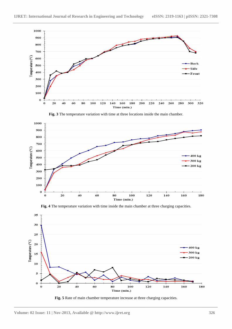
Initially, the incinerator is operated without infectious meat to determine the temperature distribution inside all the incinerator chambers. Fig. 3 shows the temperature variation with time at three locations inside the main chamber using the primary burner only and without infectious meat. It is clear in this figure that there are slight differences between the temperatures at the three locations inside the main chamber. Fig. 4 shows the temperature variation with time inside the main chamber at three charging capacities; 200 kg, 300 kg and 400 kg, and the rate of main chamber temperature increase at these capacities is shown in Fig. 5. It is clear in Fig. 4 that, initially the rate of the maximum main chamber temperature increase is high and then it decreases to a nearly constant value in a short time. This may be attributed to the fact that at the beginning of the operation of the primary burner, the drying of infectious meat takes place before its burning.
3.3 Secondary chamber temperature
The temperature of the secondary chamber is one of the most important design parameters; it must be high enough to ensure that the pollutants concentrations in the flue gas are below those limited by legislation. It is also important to note that the primary burner starts only when the secondary chamber temperature reaches 800°C. For this purpose, a control circuit is installed in the control panel of the incinerator. It may be remarked also that the secondary chamber temperature is adjusted at 1000°C to ensure that CO is completely burned and dioxin is destructed.
3.4 Flue gas temperature
The heat exchanger proved a useful method of reducing the flue gas temperature as well as increasing the economic viability of the incinerator as a heat recovery system; up to 10 m3 of hot water at temperature of 90°C can be obtained every operating day.
3.5 Fuel consumption
The fuel consumption at different charging capacities and varied maximum main chamber temperatures have been recorded. It may be remarked that lower fuel consumption is obtained at the highest value of maximum main chamber temperature at all incinerator-charging capacities. This may be attributed to at high temperatures, self- ignition of infectious meat takes places, and therefore, the accumulated shut off time of the primary burner is longer, and consequently the fuel consumption is reduced, and the burning time is shorter. However, it may be concluded that the average fuel consumption of the incinerator is 22 lit/hr.
3.6 Burning time
The burning time at different charging capacities and varied maximum main chamber temperatures have been recorded. It has been noticed that shorter burning time has been obtained at higher main chamber temperature. However, the average burning time of this incinerator is 1 hr/50kg. In other words, the hourly burning capacity of this incinerator is 50 kg of infectious meat.
IJRET: International Journal of Research in Engineering and Technology eISSN: 2319-1163 | pISSN: 2321-7308
_______________________________________________________________________________________
Volume: 02 Issue: 11 | Nov-2013, Available @ http://www.ijret.org 326
Fig. 3 The temperature variation with time at three locations inside the main chamber.
Fig. 4 The temperature variation with time inside the main chamber at three charging capacities.
Fig. 5 Rate of main chamber temperature increase at three charging capacities.
IJRET: International Journal of Research in Engineering and Technology eISSN: 2319-1163 | pISSN: 2321-7308
_______________________________________________________________________________________
Volume: 02 Issue: 11 | Nov-2013, Available @ http://www.ijret.org 327
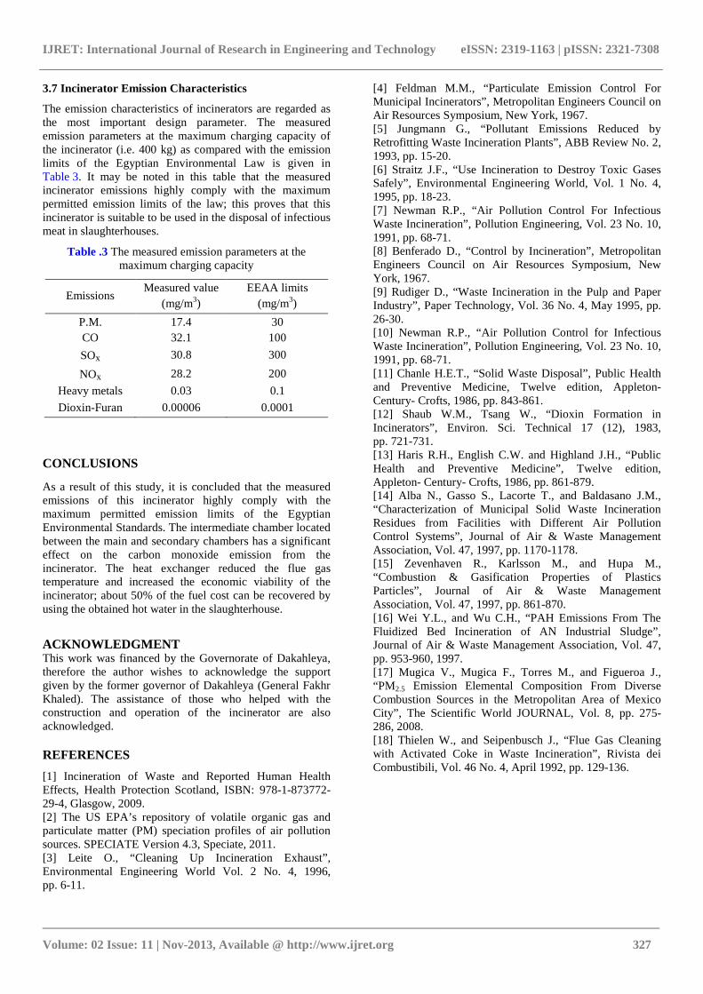
3.7 Incinerator Emission Characteristics
The emission characteristics of incinerators are regarded as the most important design parameter. The measured emission parameters at the maximum charging capacity of the incinerator (i.e. 400 kg) as compared with the emission limits of the Egyptian Environmental Law is given in Table 3. It may be noted in this table that the measured incinerator emissions highly comply with the maximum permitted emission limits of the law; this proves that this incinerator is suitable to be used in the disposal of infectious meat in slaughterhouses.
Table .3 The measured emission parameters at the maximum charging capacity
Emissions Measured value
(mg/m3) EEAA limits
(mg/m3)
P.M. 17.4 30 CO 32.1 100
SOx 30.8 300
NOx 28.2 200
Heavy metals 0.03 0.1
Dioxin-Furan 0.00006 0.0001
CONCLUSIONS
As a result of this study, it is concluded that the measured emissions of this incinerator highly comply with the maximum permitted emission limits of the Egyptian Environmental Standards. The intermediate chamber located between the main and secondary chambers has a significant effect on the carbon monoxide emission from the incinerator. The heat exchanger reduced the flue gas temperature and increased the economic viability of the incinerator; about 50% of the fuel cost can be recovered by using the obtained hot water in the slaughterhouse.
ACKNOWLEDGMENT This work was financed by the Governorate of Dakahleya, therefore the author wishes to acknowledge the support given by the former governor of Dakahleya (General Fakhr Khaled). The assistance of those who helped with the construction and operation of the incinerator are also acknowledged.
REFERENCES
[1] Incineration of Waste and Reported Human Health Effects, Health Protection Scotland, ISBN: 978-1-873772-29-4, Glasgow, 2009. [2] The US EPA’s repository of volatile organic gas and particulate matter (PM) speciation profiles of air pollution sources. SPECIATE Version 4.3, Speciate, 2011. [3] Leite O., “Cleaning Up Incineration Exhaust”, Environmental Engineering World Vol. 2 No. 4, 1996, pp. 6-11.
[4] Feldman M.M., “Particulate Emission Control For Municipal Incinerators”, Metropolitan Engineers Council on Air Resources Symposium, New York, 1967. [5] Jungmann G., “Pollutant Emissions Reduced by Retrofitting Waste Incineration Plants”, ABB Review No. 2, 1993, pp. 15-20. [6] Straitz J.F., “Use Incineration to Destroy Toxic Gases Safely”, Environmental Engineering World, Vol. 1 No. 4, 1995, pp. 18-23. [7] Newman R.P., “Air Pollution Control For Infectious Waste Incineration”, Pollution Engineering, Vol. 23 No. 10, 1991, pp. 68-71. [8] Benferado D., “Control by Incineration”, Metropolitan Engineers Council on Air Resources Symposium, New York, 1967. [9] Rudiger D., “Waste Incineration in the Pulp and Paper Industry”, Paper Technology, Vol. 36 No. 4, May 1995, pp. 26-30. [10] Newman R.P., “Air Pollution Control for Infectious Waste Incineration”, Pollution Engineering, Vol. 23 No. 10, 1991, pp. 68-71. [11] Chanle H.E.T., “Solid Waste Disposal”, Public Health and Preventive Medicine, Twelve edition, Appleton- Century- Crofts, 1986, pp. 843-861. [12] Shaub W.M., Tsang W., “Dioxin Formation in Incinerators”, Environ. Sci. Technical 17 (12), 1983, pp. 721-731. [13] Haris R.H., English C.W. and Highland J.H., “Public Health and Preventive Medicine”, Twelve edition, Appleton- Century- Crofts, 1986, pp. 861-879. [14] Alba N., Gasso S., Lacorte T., and Baldasano J.M., “Characterization of Municipal Solid Waste Incineration Residues from Facilities with Different Air Pollution Control Systems”, Journal of Air & Waste Management Association, Vol. 47, 1997, pp. 1170-1178. [15] Zevenhaven R., Karlsson M., and Hupa M., “Combustion & Gasification Properties of Plastics Particles”, Journal of Air & Waste Management Association, Vol. 47, 1997, pp. 861-870. [16] Wei Y.L., and Wu C.H., “PAH Emissions From The Fluidized Bed Incineration of AN Industrial Sludge”, Journal of Air & Waste Management Association, Vol. 47, pp. 953-960, 1997. [17] Mugica V., Mugica F., Torres M., and Figueroa J., “PM2.5 Emission Elemental Composition From Diverse Combustion Sources in the Metropolitan Area of Mexico City”, The Scientific World JOURNAL, Vol. 8, pp. 275-286, 2008. [18] Thielen W., and Seipenbusch J., “Flue Gas Cleaning with Activated Coke in Waste Incineration”, Rivista dei Combustibili, Vol. 46 No. 4, April 1992, pp. 129-136.

IJRET: International Journal of Research in Engineering and Technology eISSN: 2319-1163 | pISSN: 2321-7308
_______________________________________________________________________________________
Volume: 02 Issue: 11 | Nov-2013, Available @ http://www.ijret.org 328
BIOGRAPHY
Dr. Hamdi A. Abdel Salam is a faculty member at the Mechanical Power Eng. Dept., Mansoura University, Egypt since 1992. He is an accredited consultant in mechanical design by the Egyptian Engineering Syndicate since 1999.
Top Related