


Languages
Pages
Legal

1
PRIMERGY RX600 S2 Onboard SCSI RAID User’s Guide
Areas Covered
Before Reading This Manual
This section explains the notes for your safety and conventions used in this manual.
Chapter 1 Overview (Features / Note)
Explains the overview of the disk array and features of the SCSI array controller.
Chapter 2 How to Use WebBIOS
Explains WebBIOS setup procedures. WebBIOS is a basic utility to set up and manage the
onboard SCSI array controller. Read this chapter carefully before using WebBIOS.
Chapter 3 Installing Global Array Manager (GAM)
Explains how to install Global Array Manager (GAM) to use a SCSI array controller in a
Windows Server 2003, Windows 2000 Server, or Linux environment.
Chapter 4 How to Use GAM
GAM is a basic utility to manage the disk array. Read this chapter carefully before use.
Chapter 5 Replacing a Hard Disk
Explains maintenance related issues, such as hard disk replacement.
Appendix
Explains RAID level and list of GAM error codes.

2
Before Reading This Manual
Remarks
■ Symbols
Symbols used in this manual have the following meanings.
■ Key Descriptions / Operations
Keys are represented throughout this manual in the following manner.
E.g.: [Ctrl] key, [Enter] key, [→] key, etc.
The following indicate pressing several keys at once:
E.g.: [Ctrl] + [F3] key, [Shift] + [↑] key, etc.
■ Entering Commands (Keys)
Command entries are displayed in the following way.
• In the areas of the "↑" mark, press the [Space] key once.
• When using Windows or DOS OS, commands are not case sensitive.
• CD-ROM drive names are shown as [CD-ROM drive]. Enter your drive name according to your
environment.
[CD-ROM drive]:\setup.exe
■ Screen Shots and Figures
Screen shots and figures are used as visual aids throughout this manual. Windows, screens, and file
names may vary depending on the OS, software, or configuration of the server used. Figures in this
manual may not show cables that are actually connected for convenience of explanation.
■ Consecutive Operations
Consecutive operations are described by connecting them with arrows (→).
These sections explain prohibited actions and points to note when using this device. Make
sure to read these sections.
These sections explain information needed to operate the hardware and software properly.
Make sure to read these sections.
→ This mark indicates reference pages or manuals.
Example: Procedure of clicking the [Start] button, pointing to [Programs], and clicking [Accessories]
↓
Click [Start] → [Programs] → [Accessories].
3
PRIMERGY RX600 S2 Onboard SCSI RAID User’s Guide
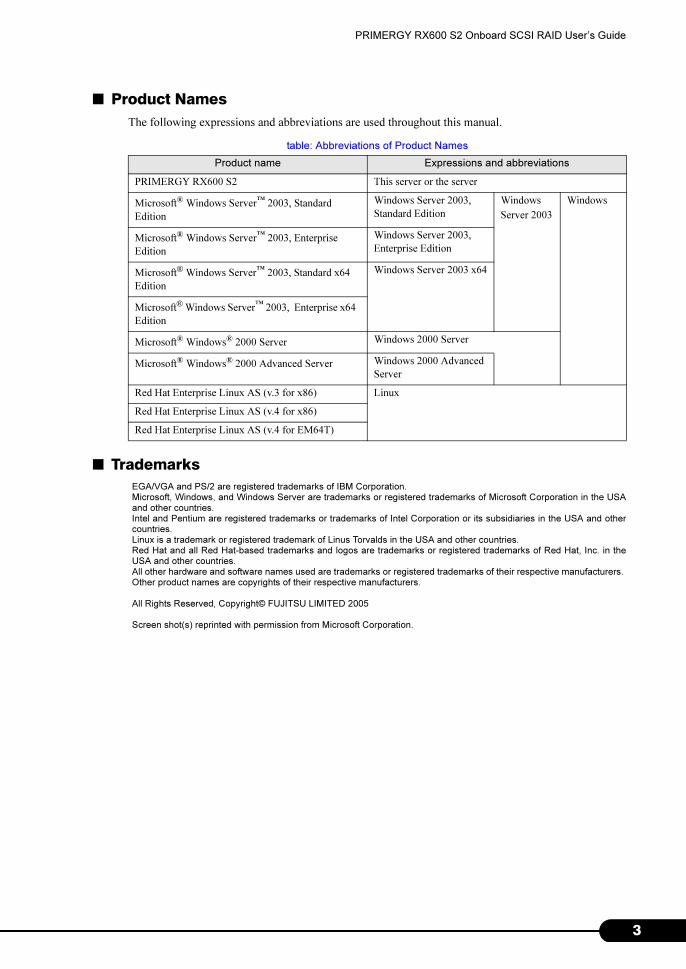
■ Product Names
The following expressions and abbreviations are used throughout this manual.
■ Trademarks
EGA/VGA and PS/2 are registered trademarks of IBM Corporation. Microsoft, Windows, and Windows Server are trademarks or registered trademarks of Microsoft Corporation in the USAand other countries.Intel and Pentium are registered trademarks or trademarks of Intel Corporation or its subsidiaries in the USA and othercountries.Linux is a trademark or registered trademark of Linus Torvalds in the USA and other countries.Red Hat and all Red Hat-based trademarks and logos are trademarks or registered trademarks of Red Hat, Inc. in theUSA and other countries.All other hardware and software names used are trademarks or registered trademarks of their respective manufacturers. Other product names are copyrights of their respective manufacturers.
All Rights Reserved, Copyright© FUJITSU LIMITED 2005
Screen shot(s) reprinted with permission from Microsoft Corporation.
table: Abbreviations of Product Names
Product name Expressions and abbreviations
PRIMERGY RX600 S2 This server or the server
Microsoft® Windows Server™ 2003, Standard
Edition
Windows Server 2003,
Standard Edition
Windows
Server 2003
Windows
Microsoft® Windows Server™ 2003, Enterprise
Edition
Windows Server 2003,
Enterprise Edition
Microsoft® Windows Server™ 2003, Standard x64
Edition
Windows Server 2003 x64
Microsoft® Windows Server™ 2003, Enterprise x64
Edition
Microsoft® Windows® 2000 Server Windows 2000 Server
Microsoft® Windows® 2000 Advanced Server Windows 2000 Advanced
Server
Red Hat Enterprise Linux AS (v.3 for x86) Linux
Red Hat Enterprise Linux AS (v.4 for x86)
Red Hat Enterprise Linux AS (v.4 for EM64T)

4
5
PRIMERGY RX600 S2 Onboard SCSI RAID User’s Guide
Contents
Chapter 1 Overview (Features / Note)
1.1 Overview . . . . . . . . . . . . . . . . . . . . . . . . . . . . . . . . . . . . . . . . . . . . 10
1.1.1 Onboard SCSI Array Controller . . . . . . . . . . . . . . . . . . . . . . . . . . . . . . . . .10
1.1.2 Disk Array . . . . . . . . . . . . . . . . . . . . . . . . . . . . . . . . . . . . . . . . . . . . . . . . . .10
1.1.3 RAID Level . . . . . . . . . . . . . . . . . . . . . . . . . . . . . . . . . . . . . . . . . . . . . . . . .10
1.1.4 Physical Pack and Logical Drive . . . . . . . . . . . . . . . . . . . . . . . . . . . . . . . . 11
1.1.5 Write Mode . . . . . . . . . . . . . . . . . . . . . . . . . . . . . . . . . . . . . . . . . . . . . . . . .12
1.1.6 Initializing a Logical Drive . . . . . . . . . . . . . . . . . . . . . . . . . . . . . . . . . . . . . .13
1.1.7 Rebuild . . . . . . . . . . . . . . . . . . . . . . . . . . . . . . . . . . . . . . . . . . . . . . . . . . . .14
1.1.8 Expand Capacity . . . . . . . . . . . . . . . . . . . . . . . . . . . . . . . . . . . . . . . . . . . .16
1.1.9 Consistency Check . . . . . . . . . . . . . . . . . . . . . . . . . . . . . . . . . . . . . . . . . .17
1.1.10 Patrol Read . . . . . . . . . . . . . . . . . . . . . . . . . . . . . . . . . . . . . . . . . . . . . . .17
Chapter 2 How to Use WebBIOS
2.1 Starting Up WebBIOS . . . . . . . . . . . . . . . . . . . . . . . . . . . . . . . . . . 20
2.1.1 How to Start Up WebBIOS . . . . . . . . . . . . . . . . . . . . . . . . . . . . . . . . . . . . .20
2.2 WebBIOS Window Layout . . . . . . . . . . . . . . . . . . . . . . . . . . . . . . 23
2.2.1 Main Menu . . . . . . . . . . . . . . . . . . . . . . . . . . . . . . . . . . . . . . . . . . . . . . . . .23
2.2.2 [Physical Drives] View . . . . . . . . . . . . . . . . . . . . . . . . . . . . . . . . . . . . . . . .24
2.2.3 [Logical Drives] View/[Configured Drives] View . . . . . . . . . . . . . . . . . . . . .24
2.3 Array Controller Properties Setting . . . . . . . . . . . . . . . . . . . . . . 25
2.3.1 SCSI Array Controller Properties Default Settings . . . . . . . . . . . . . . . . . .25
2.3.2 Viewing/Changing Array Controller Properties . . . . . . . . . . . . . . . . . . . . .27
2.3.3 How to View/Change SCSI Channel Properties . . . . . . . . . . . . . . . . . . . .27
2.4 Creating a Disk Array Configuration . . . . . . . . . . . . . . . . . . . . . 29
2.4.1 Overview of creating a disk array configuration . . . . . . . . . . . . . . . . . . . . .29
2.4.2 How to Create a Disk Array Configuration . . . . . . . . . . . . . . . . . . . . . . . . .29
2.5 Setting/Releasing a Spare Disk . . . . . . . . . . . . . . . . . . . . . . . . . 35
2.5.1 Setting a Spare Disk . . . . . . . . . . . . . . . . . . . . . . . . . . . . . . . . . . . . . . . . . .35
2.5.2 Releasing a Spare Disk . . . . . . . . . . . . . . . . . . . . . . . . . . . . . . . . . . . . . . .36
2.6 Deleting a Physical Pack . . . . . . . . . . . . . . . . . . . . . . . . . . . . . . . 37
2.7 Deleting Disk Array Configuration Information . . . . . . . . . . . . . 39
2.8 Initializing a Logical Drive . . . . . . . . . . . . . . . . . . . . . . . . . . . . . . 40
2.9 Consistency Check of Logical Drive Data . . . . . . . . . . . . . . . . . 42
2.10 Expanding Capacity of a Logical Drive . . . . . . . . . . . . . . . . . . . 44
2.11 Viewing Each Status . . . . . . . . . . . . . . . . . . . . . . . . . . . . . . . . . . 47
2.11.1 Viewing the Logical Drive Status . . . . . . . . . . . . . . . . . . . . . . . . . . . . . . .47
2.11.2 Viewing the Hard Disk Status . . . . . . . . . . . . . . . . . . . . . . . . . . . . . . . . . .49
2.12 Formatting a Hard Disk . . . . . . . . . . . . . . . . . . . . . . . . . . . . . . . 51

6
2.13 Checking a Background Task in Progress . . . . . . . . . . . . . . . . 52
2.14 Exiting WebBIOS . . . . . . . . . . . . . . . . . . . . . . . . . . . . . . . . . . . . . 53
Chapter 3 Installing Global Array Manager (GAM)
3.1 Overview / Product Requirements . . . . . . . . . . . . . . . . . . . . . . . 56
3.1.1 GAM Overview . . . . . . . . . . . . . . . . . . . . . . . . . . . . . . . . . . . . . . . . . . . . . . 56
3.1.2 Requirements for OS Drivers . . . . . . . . . . . . . . . . . . . . . . . . . . . . . . . . . . 56
3.1.3 Requirements for GAM . . . . . . . . . . . . . . . . . . . . . . . . . . . . . . . . . . . . . . . 57
3.2 Installing GAM . . . . . . . . . . . . . . . . . . . . . . . . . . . . . . . . . . . . . . . 58
3.2.1 How to Install GAM . . . . . . . . . . . . . . . . . . . . . . . . . . . . . . . . . . . . . . . . . . 58
3.2.2 Local Logon Setting on a Domain Controller . . . . . . . . . . . . . . . . . . . . . . 62
3.2.3 How to Uninstall GAM . . . . . . . . . . . . . . . . . . . . . . . . . . . . . . . . . . . . . . . . 63
3.3 Using GAM in a Linux Environment . . . . . . . . . . . . . . . . . . . . . . 65
3.4 Using GAM in a Multiple Server Environment . . . . . . . . . . . . . . 66
3.4.1 Interaction between ServerView and AlarmService . . . . . . . . . . . . . . . . . 66
Chapter 4 How to Use GAM
4.1 Overview of GAM . . . . . . . . . . . . . . . . . . . . . . . . . . . . . . . . . . . . . 70
4.1.1 About the access privileges to GAM . . . . . . . . . . . . . . . . . . . . . . . . . . . . . 70
4.2 Starting and Exiting GAM . . . . . . . . . . . . . . . . . . . . . . . . . . . . . . 71
4.2.1 Starting . . . . . . . . . . . . . . . . . . . . . . . . . . . . . . . . . . . . . . . . . . . . . . . . . . . . 71
4.2.2 Sign On (Log On) . . . . . . . . . . . . . . . . . . . . . . . . . . . . . . . . . . . . . . . . . . . 71
4.2.3 Exiting . . . . . . . . . . . . . . . . . . . . . . . . . . . . . . . . . . . . . . . . . . . . . . . . . . . . 72
4.3 Window Layout . . . . . . . . . . . . . . . . . . . . . . . . . . . . . . . . . . . . . . . 73
4.3.1 Startup Window Layout/Functions . . . . . . . . . . . . . . . . . . . . . . . . . . . . . . 73
4.3.2 [Controller View] Window Layout/Functions . . . . . . . . . . . . . . . . . . . . . . . 75
4.3.3 Menu Layout/Functions . . . . . . . . . . . . . . . . . . . . . . . . . . . . . . . . . . . . . . 77
4.3.4 Tool Bar Icons . . . . . . . . . . . . . . . . . . . . . . . . . . . . . . . . . . . . . . . . . . . . . . 79
4.4 Settings . . . . . . . . . . . . . . . . . . . . . . . . . . . . . . . . . . . . . . . . . . . . . 80
4.4.1 Server Group and Server Settings . . . . . . . . . . . . . . . . . . . . . . . . . . . . . . 80
4.4.2 Setting and Changing Controller Options . . . . . . . . . . . . . . . . . . . . . . . . . 81
4.4.3 Controller Options Window Layout/Functions . . . . . . . . . . . . . . . . . . . . . . 82
4.5 Creating and Operating a RAID Configuration . . . . . . . . . . . . . 84
4.5.1 Overview of RAID Assist . . . . . . . . . . . . . . . . . . . . . . . . . . . . . . . . . . . . . . 84
4.5.2 Creating a New RAID Configuration (New Configuration) . . . . . . . . . . . . 86
4.5.3 Adding a Logical Drive to the Existing RAID Configuration (Add Logical
Drive) . . . . . . . . . . . . . . . . . . . . . . . . . . . . . . . . . . . . . . . . . . . . . . . . . . . . . . . . . . 89
4.5.4 Expanding Capacity of a Logical Drive (Expand Array) . . . . . . . . . . . . . . 90
4.5.5 Deleting an Existing Logical Drive (Edit Configuration) . . . . . . . . . . . . . . 93
4.5.6 Setting and Releasing a Spare Disk (Edit Configuration) . . . . . . . . . . . . 94
4.5.7 Initializing a Logical Drive (Data Deletion) . . . . . . . . . . . . . . . . . . . . . . . . 95
4.5.8 Saving, Restoring and Deleting RAID Configuration Information . . . . . . 97

7
PRIMERGY RX600 S2 Onboard SCSI RAID User’s Guide
4.6 Viewing Information . . . . . . . . . . . . . . . . . . . . . . . . . . . . . . . . . . . 99
4.6.1 Event . . . . . . . . . . . . . . . . . . . . . . . . . . . . . . . . . . . . . . . . . . . . . . . . . . . . .99
4.6.2 RAID Controller . . . . . . . . . . . . . . . . . . . . . . . . . . . . . . . . . . . . . . . . . . . .101
4.6.3 Viewing Hard Disk Information . . . . . . . . . . . . . . . . . . . . . . . . . . . . . . . . .103
4.6.4 Displaying Logical Drive Information . . . . . . . . . . . . . . . . . . . . . . . . . . . .105
4.6.5 Displaying Request Sense Data / NVRAM Error Log . . . . . . . . . . . . . . .107
4.6.6 Checking the Progress of a Background Task . . . . . . . . . . . . . . . . . . . . .108
4.7 Maintenance Functions . . . . . . . . . . . . . . . . . . . . . . . . . . . . . . . 111
4.7.1 Consistency Check . . . . . . . . . . . . . . . . . . . . . . . . . . . . . . . . . . . . . . . . . 111
4.7.2 Rebuild . . . . . . . . . . . . . . . . . . . . . . . . . . . . . . . . . . . . . . . . . . . . . . . . . . . 112
Chapter 5 Replacing a Hard Disk
5.1 Replacing a Hard Disk . . . . . . . . . . . . . . . . . . . . . . . . . . . . . . . . 114
5.1.1 Replacing a Hard Disk during System Operation . . . . . . . . . . . . . . . . . . 114
5.1.2 Replacing a Hard Disk Using WebBIOS . . . . . . . . . . . . . . . . . . . . . . . . . 115
5.2 Preventive Replacement Procedure of a Hard Disk . . . . . . . . 117
5.2.1 Checking Applicability of Redundancy . . . . . . . . . . . . . . . . . . . . . . . . . . . 117
5.2.2 Preventive Replacement Procedure of a Hard Disk . . . . . . . . . . . . . . . . 118
Appendix
A RAID Level . . . . . . . . . . . . . . . . . . . . . . . . . . . . . . . . . . . . . . . . . 122A.1 RAID 1 (Mirroring) . . . . . . . . . . . . . . . . . . . . . . . . . . . . . . . . . . . . . . . . . . . .122
A.2 RAID 5 (Striping + Parity) . . . . . . . . . . . . . . . . . . . . . . . . . . . . . . . . . . . . . .123
A.3 RAID 10 (Mirroring + Striping) . . . . . . . . . . . . . . . . . . . . . . . . . . . . . . . . . .124
B List of GAM Error Codes . . . . . . . . . . . . . . . . . . . . . . . . . . . . . . 125

8

9
Chapter 1
Overview (Features / Note)
This chapter explains the overview of the disk
array and features of the SCSI array controller.
1.1 Overview . . . . . . . . . . . . . . . . . . . . . . . . . . . . . . . . . . . . 10

10
Chapter 1 Overview (Features / Note)
1.1 Overview
Explains the overview of the disk array and features of the SCSI array controller.
1.1.1 Onboard SCSI Array Controller
The following shows the SCSI array controller(MegaRAID SCSI 320-2E)explained in this manual.
� Battery for cache memory backup.
� Installation of TCP/IP and ServerView are required on all OSes, also please apply the latest Service
Pack to each OS.
� For the supported Linux distribution, refer to the latest system configuration chart.
1.1.2 Disk Array
A disk array or Redundant Array of Independent Disks (RAID) is a system that can improve
performance and reliability compared to a single hard disk, by using a disk controller and multiple hard
disks. Access to each hard disk is controlled by the disk controller, but different control methods are
used depending on the RAID level settings. It is also possible to give the disk redundancy so that the
system can be operated continuously without losing data even when one hard disk fails.
1.1.3 RAID Level
There are several types of RAID level, each of which has different characteristics. The RAID level
supported by the onboard SCSI array controller of this server is 1, 5, and 10. Depending on the RAID
level, the number of available hard disks, available capacity and applicability of redundancy are
different. The following briefly summarizes the characteristics of the supported RAID levels.
table: Performance of MegaRAID SCSI 320-2E
Items Contents
Number of SCSI channels 2
Battery Available
Cache size 256MB
OS Windows Server 2003 / Windows 2000 / Linux
table: Features of RAID Level
RAID LevelNumber of
hard disksAvailable capacity Redundancy
RAID 1 2 Capacity of 1 hard disk Applied
RAID 5 3 ~ 5 Capacity of 1 hard disk × (Number of hard disks -1) Applied
RAID 10 4 Capacity of 1 hard disk × (Number of hard disks /2) Applied
11
PRIMERGY RX600 S2 Onboard SCSI RAID User’s Guide
1
Overview
� Regardless of the applicability of redundancy, data backup should be performed as frequently as
possible just in case.
� It is recommended to specify a redundant RAID level (RAID 1, RAID 5 or RAID 10) during normal use.
With 4 or more hard disks, specify RAID 5 when priority is placed on capacity, or specify RAID 10 when
priority is placed on performance.
� For details of supported RAID levels, refer to "A RAID Level" (�pg.122).
1.1.4 Physical Pack and Logical Drive
■ Physical Pack
A physical pack is a group of physical hard disks that compose a disk array. It is not recognized by the
OS.
� A physical pack can consist of 2 to 5 hard disks.
� For hard disks in the same physical pack, use hard disks of the same model (with the same capacity
and speed) as a rule.
� Maximum capacity of one physical pack should not exceed 2TB.
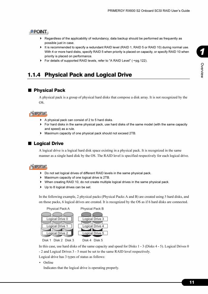
■ Logical Drive
A logical drive is a logical hard disk space existing in a physical pack. It is recognized in the same
manner as a single hard disk by the OS. The RAID level is specified respectively for each logical drive.
� Do not set logical drives of different RAID levels in the same physical pack.
� Maximum capacity of one logical drive is 2TB.
� When creating RAID 10, do not create multiple logical drives in the same physical pack.
� Up to 8 logical drives can be set.
In the following example, 2 physical packs (Physical Packs A and B) are created using 5 hard disks, and
on those packs, 6 logical drives are created. It is recognized by the OS as if 6 hard disks are connected.
In this case, use hard disks of the same capacity and speed for Disks 1 - 3 (Disks 4 - 5). Logical Drives 0
- 2 and Logical Drives 3 - 5 must be set to the same RAID level respectively.
Logical drive has 3 types of status as follows:
• Online
Indicates that the logical drive is operating properly.
Logical Drive 0
Physical Pack A Physical Pack B
Logical Drive 1
Logical Drive 2
Logical Drive 3
Logical Drive 4
Logical Drive 5
Disk 1 Disk 2 Disk 3 Disk 4 Disk 5

12
Chapter 1 Overview (Features / Note)
• Critical
Indicates that the redundant logical drive (RAID 1, RAID 5 or RAID 10) is operating without
redundancy due to a failure of 1 hard disk. In this case, replace the failed hard disk as immediately as
possible and perform the procedure to recover the status to "Online" (rebuild). For details, refer to
"1.1.7 Rebuild" (�pg.14).
• Offline
Indicates that the logical drive is not operating. This status occurs when 2 or more hard disks in a
physical pack fail. In this case, data in the logical drive will be lost.
In the case shown in the figure above, if Disk 1 in Physical Pack A fails for instance, the status of all
Logical Drives 0 - 2 becomes "Critical". If another disk (e.g. Disk 2 or 3) fails in addition, the status of
all Logical Drives 0 - 2 becomes "Offline". In this case, Logical Drives 3 - 5 of Physical Pack B remain
in "Online" status.
1.1.5 Write Mode
Write Mode or Write Cache is the mode for writing to cache memory. There are 2 modes of Write Mode:
Write Through and Write Back. The following explains these modes.
■ Write Through
In this mode, when an instruction to write data is issued from the system to a logical drive, completion of
writing instruction is reported to the system after data write to hard disk is completed.
■ Write Back
In this mode, when an instruction to write data is issued from the system to a logical drive, completion of
writing instruction is reported to the system at the same time as data is written to cache memory, and
data write to hard disk is performed later. Therefore, higher writing processing performance can be
obtained than Write Through, but risk of data loss becomes higher. This is because data that is not
written to hard disk may remain in cache memory after completion of writing instruction.

13
PRIMERGY RX600 S2 Onboard SCSI RAID User’s Guide
1
Overview
1.1.6 Initializing a Logical Drive
To use a logical drive in the optimum status, the logical drive needs to be initialized. There are 2
methods to initialize a logical drive as described below.
■ Initialization by WebBIOS
In this method, "0 (zero)" is written in all areas of logical drive to initialize before using the drive. This
requires a certain amount of time because writing operations are performed for all areas of all hard disks.
Execution time of initialization by WebBIOS per 1GB is as shown in the following table. For example,
capacity of a RAID 5 logical drive consisting of 3 units of 73GB hard disks is 146GB (= 73GB × (3 -
1)), which requires approximately 22 minutes (= approx. 9 sec./ GB × 146GB) to execute initialization.
However, the time may differ from the table depending on the configuration and hard disk type. Use the
table only as a guide.
■ Background Initialization
In this method, initialization of logical drive is performed in parallel with normal I/O access operations
from the host. If initialization by WebBIOS is not executed, background initialization is automatically
executed. This can save time for initialization by WebBIOS, but the following points must be noted.
� During background initialization, access to the hard disk may occur regardless of normal I/O access.
� When executing background initialization using a hard disk that may include data such as partition
information because of its previous use in another system, low level format of the hard disk on the
other system is required prior to physical connection (addition).
� Background initialization starts automatically when the SCSI array controller checks redundant logical
drives (RAID 1/RAID 5/RAID 10) and detects a drive that is not initialized. The SCSI array controller
checks uninitialized logical drives every 5 minutes.
� If the server is reset or turned off before completion of background initialization, background
initialization operations are stopped.
At the next restart, background initialization resumes from the block where the process stopped.
� Before completion of background initialization, I/O processing performance may be less sufficient
compared to the logical drives that have been initialized.
� During background initialization operations, the access LED of the hard disks that compose the target
logical drive remains on.
table: Estimated time of initialization by WebBIOS per 1GB
RAID level Number of hard disks Execution time per 1GB
RAID 1 2 units 18 sec./GB
RAID 53 units 9 sec./GB
5 units 3 sec./GB
RAID 10 4 units 11 sec./GB

14
Chapter 1 Overview (Features / Note)
When no normal I/O access is performed, execution time of background initialization per 1GB is as
shown in the following table. For example, capacity of a RAID 5 logical drive consisting of 3 units of
73GB hard disks is 146GB (= 73GB × (3 - 1)), which requires approximately 278 minutes (= 1.9 min./
GB × 146GB) to execute background initialization. However, if initialization is executed in parallel with
normal I/O access, longer time may be required. In addition, the time may differ from the table
depending on the configuration and hard disk type. Use the table only as a guide.
1.1.7 Rebuild
Even when 1 hard disk in a physical pack fails, if a logical drive in the physical pack has redundancy
(RAID 1, RAID 5 or RAID 10), the logical drive continues to operate in "Critical" status. However, if
another hard disk in the same physical pack fails in addition, the status of the logical drive becomes
"Offline". Rebuild is the operation to recover a logical drive in "Critical" status to "Online" status. There
are 2 methods of rebuild as described below.
■ Hot Spare (Standby) Rebuild
Hot Spare (Standby) Rebuild is rebuild performed automatically by having a spare hard disk installed in
advance. Hot Spare Rebuild is performed prior to replacement of a failed hard disk. The spare hard disk
prepared in advance is called a spare (standby) disk. The rebuild that is performed automatically prior to
replacement of the failed hard disk by having a spare hard disk installed in advance is called Hot Spare
(Standby) Rebuild. When a hard disk failure occurs, rebuild is immediately performed on the spare hard
disk, which minimizes the time in "Critical" status. This will improve system safety. The new hard disk
replaced with the failed hard disk is used as a spare disk. For how to replace hard disks, refer to "5.1
Replacing a Hard Disk" (�pg.114).
● Pay attention to the spare disk
This is required to perform a Hot Spare Rebuild. A spare disk is used as a substitute for a failed hard
disk. Pay attention to the following points.
• For the spare disk, use a hard disk of the same capacity and speed as the hard disk connected in the
physical pack.
• If a spare disk is set when multiple physical packs that use different hard disks exist, at least 1 spare
disk of the same capacity and speed must be set for each physical pack.
table: Estimated time of background initialization per 1GB
RAID level Number of hard disks Execution time per 1GB
RAID 1 2 units 2.9 min./GB
RAID 53 units 1.9 min./GB
5 units 1.2 min./GB
RAID 10 4 units 2.8 min./GB
Spare disk73GB73GB73GBPhysical
Pack A
147GB 147GB 147GBPhysical
Pack BSpare disk

15
PRIMERGY RX600 S2 Onboard SCSI RAID User’s Guide
1
Overview
■ Manual Rebuild
Manual Rebuild is rebuild performed by replacing a failed hard disk with a new hard disk. When no
spare disk is prepared, the disk array needs to be repaired through Manual Rebuild. Until replacement of
hard disks and rebuild completion, the logical drive continues to operate in "Critical" status. For how to
replace hard disks, refer to "5.1 Replacing a Hard Disk" (�pg.114).
When no normal I/O access is performed, execution time of rebuild per 1GB is as shown in the
following table. For example, capacity of a RAID 5 logical drive consisting of 3 units of 73GB hard
disks is 146GB (= 73GB × (3 - 1)), which requires approximately 219 minutes (= approx. 1.5 min./ GB
× 146GB) to execute rebuild. However, if rebuild is executed in parallel with normal I/O access, longer
time may be required. In addition, the time may differ from the table depending on the configuration and
hard disk type. Use the table only as a guide.
� The default of [Rebuild Rate] is "50%".
To reduce the time required for rebuild operation, change the [Rebuild Rate] to "100%". However, if I/O
load becomes high in 100% setting, set back the value to "50%".
After the rebuild operation is completed in 100%, restore the value to the default, "50%". [Rebuild
Rate] can be set from [Adapter Properties] of WebBIOS or from "4.4.2 Setting and Changing Controller
Options" (�pg.81) of GAM.
� If restart or shutdown is executed during the rebuild, rebuild resumes at the next launch starting from
the position where the process stopped.
table: Estimated time of manual rebuild per 1GB
RAID level Number of hard disksExecution time per 1GB
Rebuild Rate=50 Rebuild Rate=100
RAID 1 2 units 3.0 min./GB 0.4 min./GB
RAID 53 units 1.5 min./GB 0.3 min./GB
5 units 0.4 min./GB 0.2 min./GB
RAID 10 4 units 1.5 min./GB 0.3 min./GB

16
Chapter 1 Overview (Features / Note)
1.1.8 Expand Capacity
Expand Capacity is a function to expand capacity of physical packs by adding hard disks without
destroying existing data. The following figure shows an example of adding 2 hard disks to Physical Pack
A consisting of 3 hard disks. Re-striping is performed for 5 hard disks without destroying the data in the
logical drive, and the amount of capacity of the additional hard disks is added to the logical drive.
� Expand Capacity can be used only on Windows Server 2003 / Windows 2000 Server. When using
Linux, do not perform capacity expansion.
� Capacity of a RAID 10 logical drive cannot be expanded.
� When multiple logical drives are defined in a physical pack, capacity cannot be expanded.
When no normal I/O access is performed, execution time of capacity expansion per 1GB is as shown in
the following table (when 1 hard disk is added and when 3 hard disks are added). For example, capacity
of a RAID 5 logical drive consisting of 3 units of 73GB hard disks is 146GB (= 73GB × (3 - 1)), which
requires 584 minutes (= 4.0 min./ GB × 146GB) to execute capacity expansion by adding 1 hard disk.
However, if capacity expansion is performed in parallel with normal I/O access, longer time may be
required. In addition, the time may differ from the table depending on the configuration, hard disk type
and the number of added hard disks. Use the table only as a guide.
� Only capacity of logical drives is expanded by Expand Capacity. Capacity of partitions is not expanded.
table: About the RAID level after expand capacity
Current
RAID level
RAID level after capacity expansion
(When hard disk is added: RAID Migration (with addition))
RAID 1 RAID 5
RAID 5 RAID 5
RAID 10 Disabled
table: Estimated time of capacity expansion per 1GB
RAID level
before
expansion
Number of hard
disks
RAID level
after
expansion
Execution time per 1GB
When 1 unit is addedWhen 3 units are
added
RAID 1 2 units RAID 5 6.0 min./GB 3.3 min./GB
RAID 5 3 units RAID 5 4.0 min./GB 2.9 min./GB
5 units RAID 5 2.1 min./GB 1.9 min./GB
Physical Pack A Additional hard disks
Disk1 Disk2 Disk3 Disk4 Disk5
Logical Drive0
Physical Pack A
Disk1 Disk2 Disk3 Disk4 Disk5
Logical Drive0
17
PRIMERGY RX600 S2 Onboard SCSI RAID User’s Guide
1
Overview
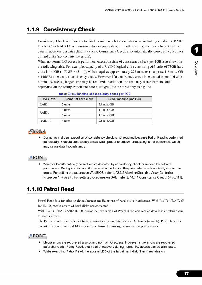
1.1.9 Consistency Check
Consistency Check is a function to check consistency between data on redundant logical drives (RAID
1, RAID 5 or RAID 10) and mirrored data or parity data, or in other words, to check reliability of the
data. In addition to a data reliability check, Consistency Check also automatically corrects media errors
of hard disks (not consistency errors).
When no normal I/O access is performed, execution time of consistency check per 1GB is as shown in
the following table. For example, capacity of a RAID 5 logical drive consisting of 3 units of 73GB hard
disks is 146GB (= 73GB × (3 - 1)), which requires approximately 278 minutes (= approx. 1.9 min./ GB
× 146GB) to execute a consistency check. However, if a consistency check is executed in parallel with
normal I/O access, longer time may be required. In addition, the time may differ from the table
depending on the configuration and hard disk type. Use the table only as a guide.
� During normal use, execution of consistency check is not required because Patrol Read is performed
periodically. Execute consistency check when proper shutdown processing is not performed, which
may cause data inconsistency.
� Whether to automatically correct errors detected by consistency check or not can be set with
parameters. During normal use, it is recommended to set the parameter to automatically correct the
errors. For setting procedures on WebBIOS, refer to "2.3.2 Viewing/Changing Array Controller
Properties" (�pg.27). For setting procedures on GAM, refer to "4.7.1 Consistency Check" (�pg.111).
1.1.10 Patrol Read
Patrol Read is a function to detect/correct media errors of hard disks in advance. With RAID 1/RAID 5/
RAID 10, media errors of hard disks are corrected.
With RAID 1/RAID 5/RAID 10, periodical execution of Patrol Read can reduce data loss at rebuild due
to media errors.
The Patrol Read function is set to be automatically executed every 168 hours (a week). Patrol Read is
executed when no normal I/O access is performed, causing no impact on performance.
� Media errors are recovered also during normal I/O access. However, if the errors are recovered
beforehand with Patrol Read, overhead at recovery during normal I/O access can be eliminated.
� While executing Patrol Read, the access LED of the target hard disk (1 unit) remains on.
table: Execution time of consistency check per 1GB
RAID level Number of hard disks Execution time per 1GB
RAID 1 2 units 2.9 min./GB
RAID 53 units 1.9 min./GB
5 units 1.2 min./GB
RAID 10 4 units 2.8 min./GB

18
Chapter 1 Overview (Features / Note)

19
Chapter 2
How to Use WebBIOS
This chapter explains WebBIOS setup
procedures. WebBIOS is a basic utility to set up
and manage the onboard SCSI array controller.
Read this chapter carefully before using
WebBIOS.
2.1 Starting Up WebBIOS . . . . . . . . . . . . . . . . . . . . . . . . . . . 20
2.2 WebBIOS Window Layout . . . . . . . . . . . . . . . . . . . . . . . . 23
2.3 Array Controller Properties Setting . . . . . . . . . . . . . . . . . . 25
2.4 Creating a Disk Array Configuration . . . . . . . . . . . . . . . . . 29
2.5 Setting/Releasing a Spare Disk . . . . . . . . . . . . . . . . . . . . 35
2.6 Deleting a Physical Pack . . . . . . . . . . . . . . . . . . . . . . . . . 37
2.7 Deleting Disk Array Configuration Information . . . . . . . . . 39
2.8 Initializing a Logical Drive . . . . . . . . . . . . . . . . . . . . . . . . 40
2.9 Consistency Check of Logical Drive Data . . . . . . . . . . . . . 42
2.10 Expanding Capacity of a Logical Drive . . . . . . . . . . . . . . . 44
2.11 Viewing Each Status . . . . . . . . . . . . . . . . . . . . . . . . . . . . 47
2.12 Formatting a Hard Disk . . . . . . . . . . . . . . . . . . . . . . . . . . 51
2.13 Checking a Background Task in Progress . . . . . . . . . . . . 52
2.14 Exiting WebBIOS . . . . . . . . . . . . . . . . . . . . . . . . . . . . . . 53
20
Chapter 2 How to Use WebBIOS
2.1 Starting Up WebBIOS
This section explains how to start up WebBIOS. Start of WebBIOS can be instructed
from the BIOS at system startup, regardless of whether the OS has been installed or
not on the computer to be used.
� To use the WebBIOS, the mouse needs to be connected. Before starting the WebBIOS, make sure the
mouse is connected. Also, to make available the mouse, press the [Ctrl] and [H] key in the onboard
SCSI RAID controller POST screen which is displayed as "Mega RAID SCSI 320-2E" on starting up
the WebBIOS.
Even if you install the SCSI RAID (PG-142E3) and press the [Ctrl] and [H] key in the PG-142E3 POST
screen, mouse is not available. Restart the system.
2.1.1 How to Start Up WebBIOS
Perform the following procedure to start up WebBIOS.
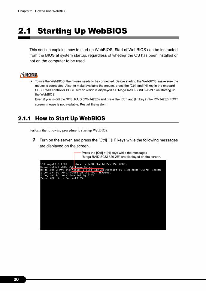
1 Turn on the server, and press the [Ctrl] + [H] keys while the following messages
are displayed on the screen.
Press the [Ctrl] + [H] keys while the messages
"Mega RAID SCSI 320-2E" are displayed on the screen.

21
PRIMERGY RX600 S2 Onboard SCSI RAID User’s Guide
2
How
to U
se W
ebB
IOS
� Press the [Ctrl] + [H] keys while the message "Press <CTRL><H> for WebBIOS" is displayed
in the last line on the screen.
� If the following error message is displayed during POST, the message "Press <CTRL><H> for
WebBIOS" is not displayed. The system is automatically restarted when POST completes and
configuration information of the hard disk is restored. Do not use WebBIOS.
� If the following error message is displayed during POST phase, stop the operation and contact
an office listed in the "Contact Information" of the "Start Guide".
The following message appears and WebBIOS starts up after system BIOS operations complete.
When WebBIOS starts, the [Adapter Selection] window of WebBIOS appears. If any other array
card is mounted at the same time, multiple SCSI array controllers are displayed.
� For the onboard SCSI array controller, [Type] in the window shown above is displayed as
"MegaRAID SCSI 320-2E".
Configuration of NVRAM and drives mismatch.
Press any key to enter the Configuration Utility.
Unresolved configuration mismatch between
disk(s)and NVRAM on the adapter
WebBIOS will be executed after POST is over

22
Chapter 2 How to Use WebBIOS
2 Select the SCSI array controller to be accessed, and click [Start].
The main window appears.

23
PRIMERGY RX600 S2 Onboard SCSI RAID User’s Guide
2
How
to U
se W
ebB
IOS
2.2 WebBIOS Window Layout
Start WebBIOS and select a SCSI array controller (when multiple SCSI array
controllers are installed). The main menu of WebBIOS will appear.
The main menu of WebBIOS consists of 3 areas.
2.2.1 Main Menu
This is the main menu of WebBIOS.
table: Main menu of WebBIOS
Menu Description
Adapter Properties Allows you to view/change the properties settings of the array controller.
Scan Devices Redetects the hard disks connected.
SCSI Channel Properties Configures the [SCSI Channel] properties.
Logical Drives This function is not supported. Do not use this function.
Physical Drives This function is not supported. Do not use this function.
Configuration Wizard Creates and adds/deletes RAID configurations.
Adapter Selection Switches array controllers.
Physical View Displays the [Configured Drives] view.
Logical View Displays the [Logical Drives] view.
Exit Exits WebBIOS.
"Physical Drives" View
"Logical Drives" View / "Configured Drives" ViewMain Menu

24
Chapter 2 How to Use WebBIOS
2.2.2 [Physical Drives] View
Displays all channels of SCSI array controllers and hard disks connected to each channel. Also displays
the status of each hard disk.
2.2.3 [Logical Drives] View/[Configured Drives] View
The [Logical Drives] view displays the relationship between a physical pack (Array) and logical drives.
This also displays the RAID level, capacity and status of logical drives.
The [Configured Drives] view displays the relationship between a physical pack and the hard disks that
compose the physical pack. This also displays the status and capacity of hard disks.
� The [Logical Drives] view and the [Configured Drives] view can be switched by selecting [Logical View]
or [Physical View] from the main menu.
� With RAID 10, the first logical drive is displayed as "RAID 1". Other logical drives are displayed as
"(Contd)".

25
PRIMERGY RX600 S2 Onboard SCSI RAID User’s Guide
2
How
to U
se W
ebB
IOS
2.3 Array Controller Properties Setting
Array controller settings can be checked using WebBIOS. Before creating an array
configuration, make sure to check the array controller settings.
2.3.1 SCSI Array Controller Properties Default Settings
The properties of the SCSI array controller need to be configured as follows. However, [Rebuild Rate]
and [ChkConst Restore] can be changed.
table: SCSI Array Controller Properties Default Settings
Properties Parameter Default setting
Adapter Properties Battery Backup Present (Fixed value)
RAM Size 256MB (Fixed value)
Cluster Mode Disabled
Initiator ID 7
Rebuild Rate 50
Flex RAID Power Fail Enabled
Alarm Control Disabled
Adapter BIOS Enabled
Set Factory Defaults No
ChkConst Restore Enabled
Force Boot Option On
Bios Stops on Error Off
BIOS Echoes Messages On
Bios Config Auto Selection DISK
Spin up Parameters 2 per 6 sec
Fast Initialization Disabled
PCI Delay Trans Enabled
Auto Rebuild Enabled
Class Emulation Mode Mass Storage
Temporary RAID Offline Enabled
SCSI Channel Properties
(both for Channel 0/Channel 1)
Termination Enabled
SCSI Capabilities U320

26
Chapter 2 How to Use WebBIOS
■ Property Details
The meaning of each parameter of Adapter Properties is shown in the table below.
table: meaning of each parameter of Adapter Properties
Parameter Meaning
Battery Backup Specifies whether a battery is installed or not. In this product, "Present" is fixed
values.
RAM Size Specifies the memory size of RAM for cache. In this product, "256MB" is fixed
values.
Cluster Mode This parameter is not supported. Do not change this.
Initiator ID Specifies the SCSI ID of the initiator. For this product, set this parameter to "7".
Rebuild Rate Specifies the priority of rebuilding.
The default value is 50. If it is changed to 100, rebuild time can be reduced.
Flex RAID Power Fail Specifies whether continued operation of capacity expansion is enabled/disabled
after power off. For this product, set this parameter to "Enabled".
Alarm Control Controls the speaker for alarm on the card of this product. For this product, set this
parameter to "Disabled".
Adapter BIOS Specifies whether BootBIOS in the card is enabled/disabled. The default value is
"Enabled".
Set Factory Defaults This parameter is used to restore when settings buying it. Do not use this during
normal use.
ChkConst Restore Specifies whether automatic correction of errors detected by consistency check is
performed or not. When set to "Disabled", detected errors are not corrected
automatically.
Force Boot Option Continues the startup process without waiting for key entry when startup is
available.
Bios Stops on Error Stops in POST when a problem is detected in configuration information during
startup.
BIOS Echoes Messages Specifies whether POST messages are displayed on screen or not.
When set to "Disabled", the message "press [Ctrl] [H]" is not displayed during
POST of MegaRAID. Although the message is not displayed, pressing [Ctrl] and
[H] allows entry to WebBIOS.
Bios Config Auto Selection Specifies the source to read array configuration information. For this product, set
this parameter to "DISK".
Spin up Parameters Specifies the number of hard disk drives that start rotating at the same time and the
parameter of rotation start between hard disk drives in sequence. For this product,
set this parameter to "2per6sec".
Fast Initialization This parameter is not supported. For this product, set this parameter to "Disabled".
PCI Delay Trans Specifies whether PCI delayed transfer is enabled/disabled. For this product, set
this parameter to "Enabled".
Auto Rebuild Specifies whether rebuild is performed automatically or not after detecting a failed
hard disk drive and installing a new hard disk drive.
Class Emulation Mode Only "Mass storage class" is supported. Set this parameter to "Mass Storage".
Temporary RAID Offline Specifies whether the function to handle a failed hard disk drive used for an array in
"Critical" status temporarily as "Online" is enabled/disabled. The default value is
"Enabled".
Termination Specifies whether termination of the SCSI array controller is enabled/disabled. For
this product, set this parameter to "Enabled".
SCSI Capabilities Specifies the SCSI transfer capability of the SCSI array controller. For this product,
set this parameter to "U320".

27
PRIMERGY RX600 S2 Onboard SCSI RAID User’s Guide
2
How
to U
se W
ebB
IOS
2.3.2 Viewing/Changing Array Controller Properties
Perform the following procedure to check properties of the SCSI array controller.
1 Select the array controller to set from the [Adapter Selection] window, and click
[Start].
2 Click [Adapter Properties]. The [Properties] window of the SCSI array controller
appears.
Check and change the settings for each option, referring to the table in "2.3.1 SCSI Array
Controller Properties Default Settings" (�pg.25).
3 Check that the settings are properly configured, and click [Submit].
The properties are committed with the settings currently displayed.
� Click [Home] to return to the main menu.
2.3.3 How to View/Change SCSI Channel Properties
Perform the following procedure to check the SCSI Channel properties. Configure the setting for each
channel (Channel 0/Channel 1).
1 Select the array controller to set from the [Adapter Selection] window, and click
[Start].
The main menu of WebBIOS appears.
28
Chapter 2 How to Use WebBIOS
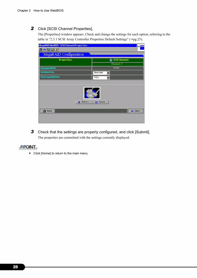
2 Click [SCSI Channel Properties].
The [Properties] window appears. Check and change the settings for each option, referring to the
table in "2.3.1 SCSI Array Controller Properties Default Settings" (�pg.25).
3 Check that the settings are properly configured, and click [Submit].
The properties are committed with the settings currently displayed.
� Click [Home] to return to the main menu.

29
PRIMERGY RX600 S2 Onboard SCSI RAID User’s Guide
2
How
to U
se W
ebB
IOS
2.4 Creating a Disk Array Configuration
This section explains how to create a disk array configuration.
2.4.1 Overview of creating a disk array configuration
An overview of procedures for creating a disk array configuration is as follows.
• Selecting creation of a new configuration or addition of configuration to the current configuration
• Creating a physical pack
• Selecting the RAID level
• Setting the Write mode
• Setting capacity of the logical drive
• Setting a spare disk
When using RAID 10, note the following points.
• RAID 10 logical drives cannot be created using GAM. Create them using WebBIOS.
• For RAID 10 logical drives, capacity expansion and RAID level conversion are not available.
• In a physical pack of RAID 10, multiple logical drives cannot be defined.
• Do not create a physical pack for RAID 1/RAID 5 at the same time as creating RAID 10.
2.4.2 How to Create a Disk Array Configuration
Perform the following procedure to set a disk array configuration.
1 Click [Configuration Wizard] from the main menu.
The [Configuration Wizard] window appears.
30
Chapter 2 How to Use WebBIOS
2 Select [New Configuration] when creating a new disk array configuration, or
[Add Configuration] when adding a logical drive to the current disk array
configuration. Then click [Next].
� If [New Configuration] is used when a disk array configuration already exists, the current con-
figuration is deleted. Note that data in the disk array is also deleted.
� To add a new logical drive while keeping the existing logical drive, use [Add Configuration].
� If [New Configuration] is selected when a RAID configuration already exists, the warning mes-
sage as shown below is displayed. If you want to delete the existing configuration, click [Yes] to
proceed.
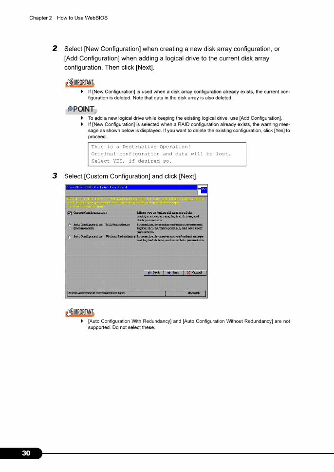
3 Select [Custom Configuration] and click [Next].
� [Auto Configuration With Redundancy] and [Auto Configuration Without Redundancy] are not
supported. Do not select these.
This is a Destructive Operation!
Original configuration and data will be lost.
Select YES, if desired so.
31
PRIMERGY RX600 S2 Onboard SCSI RAID User’s Guide
2
How
to U
se W
ebB
IOS
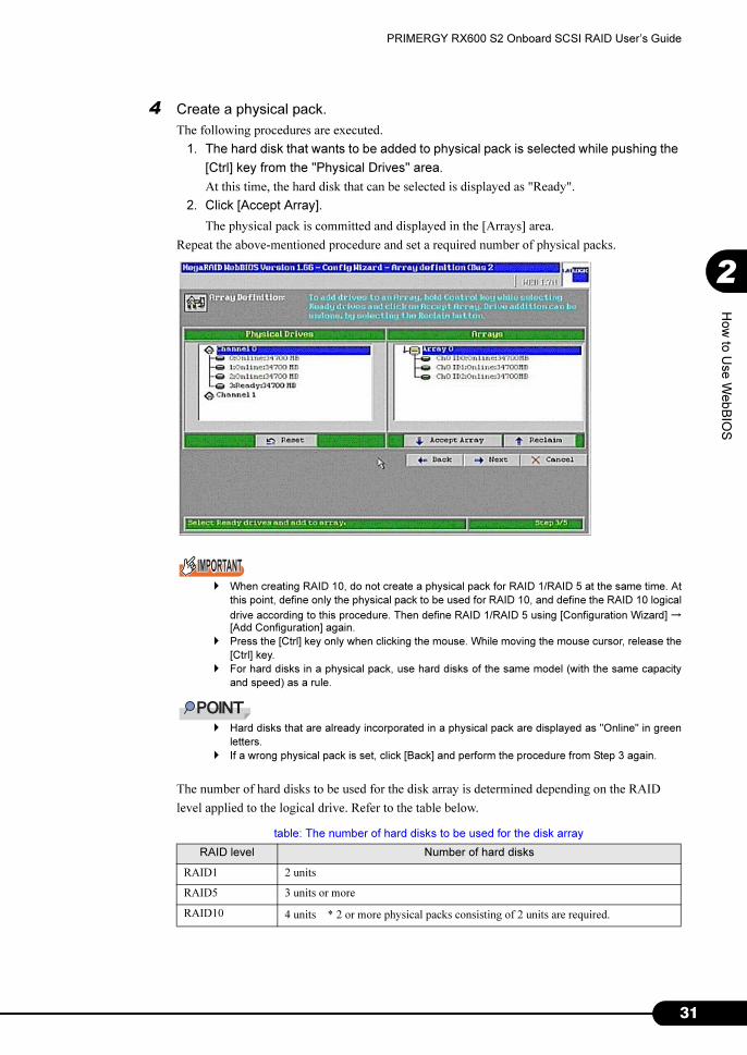
4 Create a physical pack.
The following procedures are executed.
1. The hard disk that wants to be added to physical pack is selected while pushing the
[Ctrl] key from the "Physical Drives" area.
At this time, the hard disk that can be selected is displayed as "Ready".
2. Click [Accept Array].
The physical pack is committed and displayed in the [Arrays] area.
Repeat the above-mentioned procedure and set a required number of physical packs.
� When creating RAID 10, do not create a physical pack for RAID 1/RAID 5 at the same time. At
this point, define only the physical pack to be used for RAID 10, and define the RAID 10 logical
drive according to this procedure. Then define RAID 1/RAID 5 using [Configuration Wizard] →[Add Configuration] again.
� Press the [Ctrl] key only when clicking the mouse. While moving the mouse cursor, release the
[Ctrl] key.
� For hard disks in a physical pack, use hard disks of the same model (with the same capacity
and speed) as a rule.
� Hard disks that are already incorporated in a physical pack are displayed as "Online" in green
letters.
� If a wrong physical pack is set, click [Back] and perform the procedure from Step 3 again.
The number of hard disks to be used for the disk array is determined depending on the RAID
level applied to the logical drive. Refer to the table below.
table: The number of hard disks to be used for the disk array
RAID level Number of hard disks
RAID1 2 units
RAID5 3 units or more
RAID10 4 units * 2 or more physical packs consisting of 2 units are required.

32
Chapter 2 How to Use WebBIOS
5 When defining of the physical pack is completed, click [Next].
The [Logical drive definition] window appears. Creates the logical drive from the physical pack
with the smallest number.
(For example, if the [Configuration] area has physical packs named "Array0" and "Array1,"
defining the logical drive starts from the physical pack "Array0.")
6 Select [RAID Level] to set for the logical drive.
� Do not create logical drives of different RAID levels in a single physical pack.
� Do not create logical drives of different RAID levels in a single physical pack.
Set [RAID Level] to RAID 1 when creating RAID 10 logical drives. This requires 2 or more
unused consecutive physical packs consisting of 2 hard disks.
7 Set [Stripe Size], [Read Policy] and [Cache Policy] as follows:
8 In [Select Size], enter capacity of the logical drive to be created in units of MB.
The maximum value of capacity that can be entered here is: the value displayed in [Without
Spanning] in case of RAID 1/RAID 5, and the value displayed in [With Spanning] in case of
RAID 10. When creating multiple logical drives in a physical pack, specify a value of the
maximum capacity or less so as to leave space for logical drives to be defined later.
table: Set value
Items Set value
Stripe Size 64KB
Read Policy No Read Ahead
Cache Policy Direct IO

33
PRIMERGY RX600 S2 Onboard SCSI RAID User’s Guide
2
How
to U
se W
ebB
IOS
� When creating a RAID 10 logical drive, the maximum value (the value displayed in [RAID 10
size] below [With Spanning]) must be set to [Select Size] and multiple RAID 10 logical drives
cannot be created in a physical pack.
9 Add the logical drive.
Click [Accept]. The logical drive is added under the physical pack in the [Configuration] area. If
capacity to set other logical drives remains or if there is a physical drive for which no logical
drive is set, the [Logical drive definition] window appears again. Return to Step 5, and define
logical drives until no free space remains in the physical pack. When there is no more free space
in the physical pack, the [Configuration Preview] window appears.
• Example of the window in case of RAID 1/RAID 5

34
Chapter 2 How to Use WebBIOS
• Example of the window in case of RAID 10
� The first logical drive of the logical drives included in RAID 10 is displayed as "RAID 1". Other
logical drives in RAID 10 are displayed as "(Contd)". All logical drives are displayed with the
same number, indicating that one logical drive consists of multiple logical drives.
10 Check the [Physical Drives] area and the [Logical Drives] area.
If no mistakes are found, click [Accept] to write the content that has been set. When the message
"Save this Configuration?" appears, click [Yes]. The message "Want to Initialize the New Logical
Drives?" appears.
11 Click [No] to perform background initialization, or click [Yes] to perform
foreground initialization.
� It is not necessary to perform initialization at this point, because background initialization is
supported.
If foreground initialization is performed by clicking [Yes], the array controller cannot be operated
until the initialization completes.
12 Click [Home] to return to the main menu.

35
PRIMERGY RX600 S2 Onboard SCSI RAID User’s Guide
2
How
to U
se W
ebB
IOS
2.5 Setting/Releasing a Spare Disk
This section explains how to set a hard disk in Ready state as a spare disk and how
to release an existing spare disk.
2.5.1 Setting a Spare Disk
Set a hard disk in Ready state as a spare disk according to the following procedure.
1 Click the hard disk in Ready state to be set as a spare disk from the [Physical
Drives] area in the main menu.
2 Select [Make Hotspare] from [Select an Operation] displayed at the bottom of
the window, and click [Go].
Check that [State] becomes "Hotspare".
3 Click [Home] to return to the main menu.

36
Chapter 2 How to Use WebBIOS
2.5.2 Releasing a Spare Disk
A hard disk in Hotspare state can be restored to the Ready state according to the following procedure.
1 Click the hard disk in Hotspare state to be restored to the Ready state from the
[Physical Drives] area in the main menu.
Check that [State] displayed in [Properties] is "Hotspare".
2 Select [Offline] from [Select an Operation] displayed at the bottom of the
window, and click [Go].
Check that [State] becomes "Ready".
3 Click [Home] to return to the main menu.

37
PRIMERGY RX600 S2 Onboard SCSI RAID User’s Guide
2
How
to U
se W
ebB
IOS
2.6 Deleting a Physical Pack
Deleting all of the logical drives that configure the physical pack can restore the hard
disks that compose the physical pack to the Ready state.
To delete a logical drive using WebBIOS, perform the following procedure.
� Only the logical drive with the largest ID can be deleted.
1 Display the [Logical Drives] view from the main menu.
If [Configured Drives] is displayed in the lower right area of the window, click [Logical View] in
the main menu to display the [Logical Drives] view.
2 Click the logical drive displayed at the bottom of the [Logical Drives] view.

38
Chapter 2 How to Use WebBIOS
3 Select [Delete] from the [Operations] area in the lower left of the window, and
click [Go].
4 If no mistakes are found, click [Yes].

39
PRIMERGY RX600 S2 Onboard SCSI RAID User’s Guide
2
How
to U
se W
ebB
IOS
2.7 Deleting Disk Array Configuration Information
To delete the entire current disk array configuration, use the [Clear Configuration]
function of [Configuration Wizard]. After the disk array configuration is deleted, data
currently contained in the hard disk cannot be accessed any more. Allocation
information in the disk array is completely deleted, and all hard disks are restored to
the Ready state.
� Do not use this function during normal use.
� If this function is used, the current settings on the array controller are deleted and data on all hard
disks connected to the array controller is also deleted. When using this option, make appropriate plans
and proceed carefully.
1 Click [Adapter Selection] from the main menu and select the array controller
whose disk array configuration is to be deleted.
When no other array controllers are installed, it is not necessary to select array controllers.
2 Click [Configuration Wizard] from the main menu.
3 Select [Clear Configuration] and click [Next].
When the following warning message appears, click [Yes].
4 When the [Configuration Preview] window appears, click the [Accept] button.
When the message "Save this Configuration?" appears, click [Yes]. Allocation of all logical
drives is deleted, and the state of all hard disks connected to the array controller becomes Ready.
This is Destructive Operation!
Original configuration and data will be lost.
Select Yes, if desired so.
40
Chapter 2 How to Use WebBIOS
2.8 Initializing a Logical Drive
This section explains how to initialize a logical drive using WebBIOS.
Disk arrays can usually be used immediately after disk array configuration is set,
because background initialization is supported.
� Note that initialization of a logical drive will delete the data in the target logical drive.
� It is not necessary to perform initialization using this function after creating a logical drive, because
background initialization is supported.
� While background initialization is being executed, this function cannot be used.
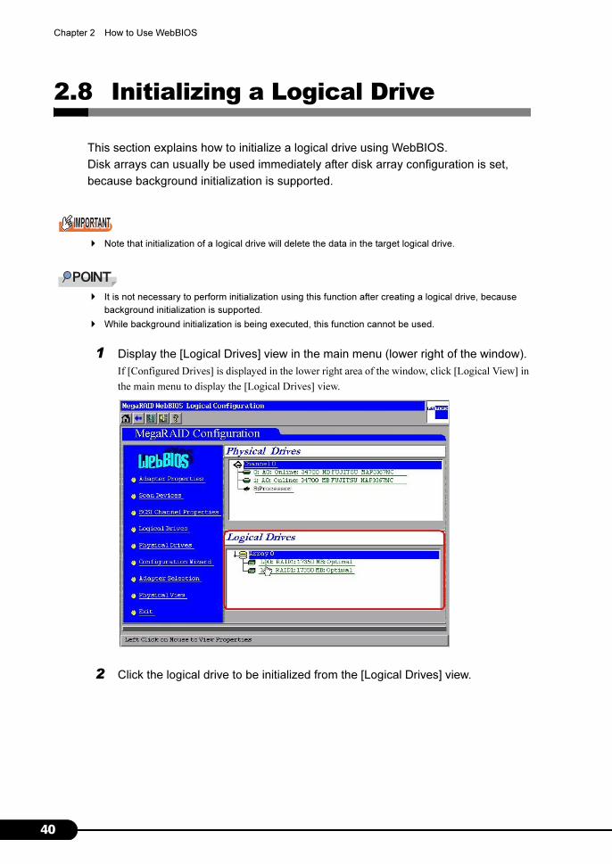
1 Display the [Logical Drives] view in the main menu (lower right of the window).
If [Configured Drives] is displayed in the lower right area of the window, click [Logical View] in
the main menu to display the [Logical Drives] view.
2 Click the logical drive to be initialized from the [Logical Drives] view.
41
PRIMERGY RX600 S2 Onboard SCSI RAID User’s Guide
2
How
to U
se W
ebB
IOS
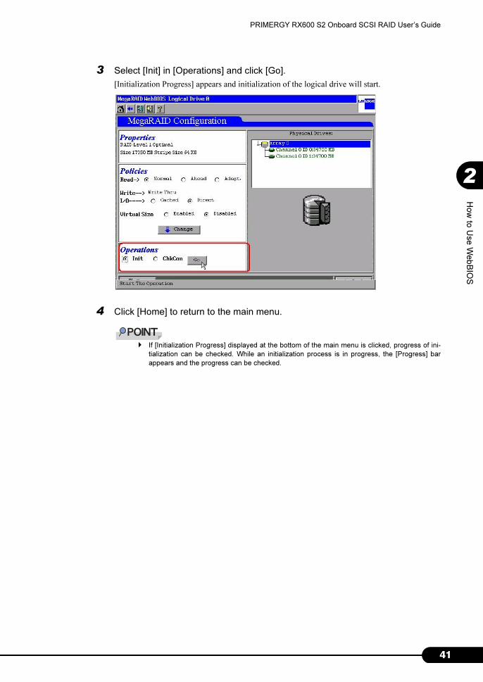
3 Select [Init] in [Operations] and click [Go].
[Initialization Progress] appears and initialization of the logical drive will start.
4 Click [Home] to return to the main menu.
� If [Initialization Progress] displayed at the bottom of the main menu is clicked, progress of ini-
tialization can be checked. While an initialization process is in progress, the [Progress] bar
appears and the progress can be checked.

42
Chapter 2 How to Use WebBIOS
2.9 Consistency Check of Logical Drive Data
Consistency Check of the logical drive is a function to check reliability of the data.
check the consistency between data on redundant logical drives and mirrored data or
parity data.
� Note that consistency checks can be performed on logical drives with redundancy such as Optimal
RAID 1/RAID 5/RAID 10 logical drives. Consistency checks cannot be performed on logical drives
without redundancy such as Degraded and Offline logical drives.
� In addition to the function to check consistency, Consistency Check also automatically corrects media
errors of hard disks (physical errors that can be recovered, not data consistency errors).
To execute a data consistency check of a logical drive using WebBIOS, perform the following
procedure.
1 Display the [Logical Drives] view from the main menu.
If [Configuration Drives] is displayed in the lower right area of the window, click [Logical View]
in the main menu to display the [Logical Drives] view.
2 Click the logical drive to check consistency from the [Logical Drives] view.
3 Select [ChkCon] from [Operations] in the lower left of the window, and click
[Go].
Consistency check starts and the progress is displayed.
43
PRIMERGY RX600 S2 Onboard SCSI RAID User’s Guide
2
How
to U
se W
ebB
IOS
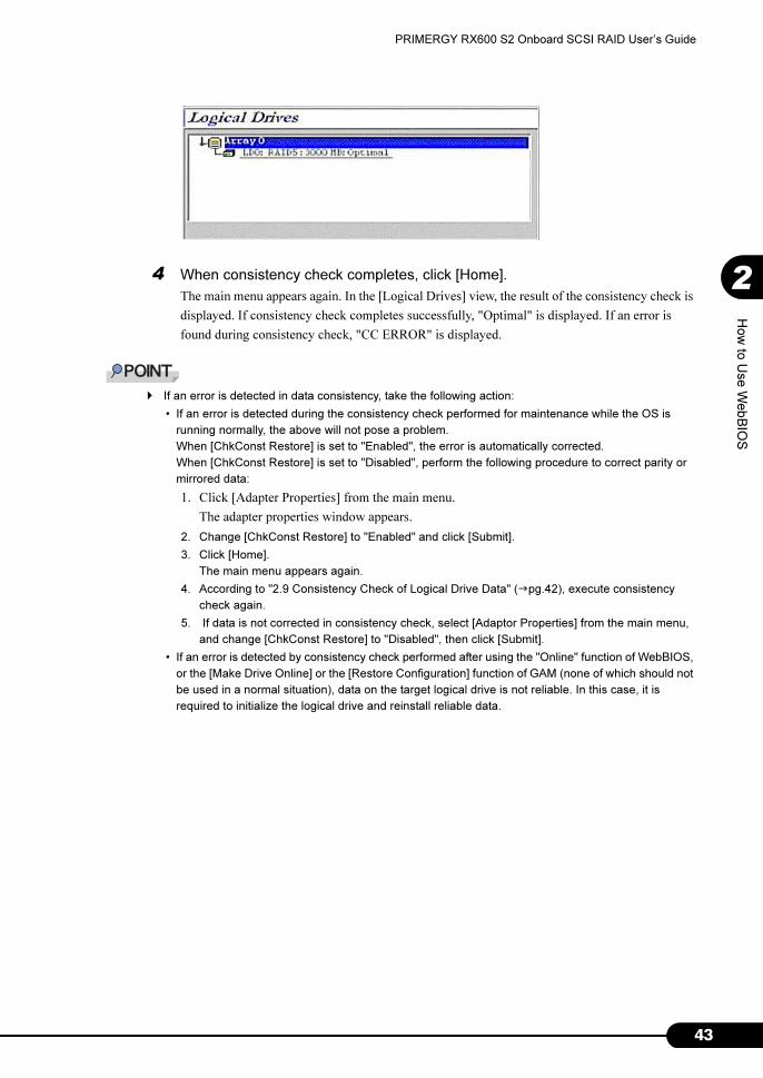
4 When consistency check completes, click [Home].
The main menu appears again. In the [Logical Drives] view, the result of the consistency check is
displayed. If consistency check completes successfully, "Optimal" is displayed. If an error is
found during consistency check, "CC ERROR" is displayed.
� If an error is detected in data consistency, take the following action:
• If an error is detected during the consistency check performed for maintenance while the OS is
running normally, the above will not pose a problem.
When [ChkConst Restore] is set to "Enabled", the error is automatically corrected.
When [ChkConst Restore] is set to "Disabled", perform the following procedure to correct parity or
mirrored data:
1. Click [Adapter Properties] from the main menu.
The adapter properties window appears.
2. Change [ChkConst Restore] to "Enabled" and click [Submit].
3. Click [Home].
The main menu appears again.
4. According to "2.9 Consistency Check of Logical Drive Data" (�pg.42), execute consistency
check again.
5. If data is not corrected in consistency check, select [Adaptor Properties] from the main menu,
and change [ChkConst Restore] to "Disabled", then click [Submit].
• If an error is detected by consistency check performed after using the "Online" function of WebBIOS,
or the [Make Drive Online] or the [Restore Configuration] function of GAM (none of which should not
be used in a normal situation), data on the target logical drive is not reliable. In this case, it is
required to initialize the logical drive and reinstall reliable data.
44
Chapter 2 How to Use WebBIOS
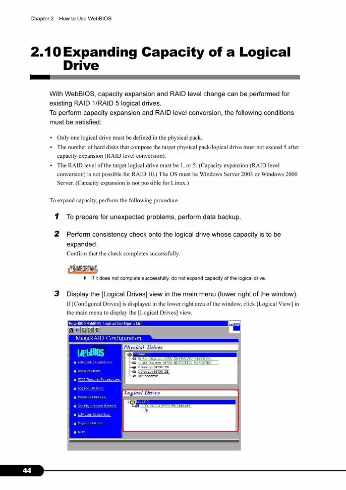
2.10Expanding Capacity of a Logical Drive
With WebBIOS, capacity expansion and RAID level change can be performed for
existing RAID 1/RAID 5 logical drives.
To perform capacity expansion and RAID level conversion, the following conditions
must be satisfied:
• Only one logical drive must be defined in the physical pack.
• The number of hard disks that compose the target physical pack/logical drive must not exceed 5 after
capacity expansion (RAID level conversion).
• The RAID level of the target logical drive must be 1, or 5. (Capacity expansion (RAID level
conversion) is not possible for RAID 10.) The OS must be Windows Server 2003 or Windows 2000
Server. (Capacity expansion is not possible for Linux.)
To expand capacity, perform the following procedure.
1 To prepare for unexpected problems, perform data backup.
2 Perform consistency check onto the logical drive whose capacity is to be
expanded.
Confirm that the check completes successfully.
� If it does not complete successfully, do not expand capacity of the logical drive.
3 Display the [Logical Drives] view in the main menu (lower right of the window).
If [Configured Drives] is displayed in the lower right area of the window, click [Logical View] in
the main menu to display the [Logical Drives] view.

45
PRIMERGY RX600 S2 Onboard SCSI RAID User’s Guide
2
How
to U
se W
ebB
IOS
4 Click the logical drive whose capacity is to be expanded from the [Logical
Drives] window.
The following window appears. To expand capacity by adding a new hard disk, select [RAID
Migration (with addition)] in the right side of the window. To expand capacity without adding a
new hard disk, select [RAID Migration only].
� Do not select [Remove physical drive].
5 Select the RAID level to be set after capacity expansion from the box in the
center of the right side of the window.
Select RAID5 to add the hard disk and enhance capacity when an existing logical drive is
composed of RAID1. If the drive has been already composed of RAID5, you do not need to
change the RAID level.
� Please do not select RAID0 in this product for the unsupport. Though "RAID0" is displayed
when the select the RAID level after capacity expansion.
6 In the lower right area of the window, a list of unused hard disks is displayed.
If [RAID Migration (with addition)] is selected, select a hard disk to be added to expand capacity.
� Multiple hard disks can be selected at a time with holding down the [Ctrl] key.
� Press the [Ctrl] key only when clicking the mouse. While moving the mouse cursor, release the
[Ctrl] key.
7 Click [Go] in the lower right of the window.
[Reconstruction Progress] appears and a capacity expansion process will start. Wait until the
process is completed.

46
Chapter 2 How to Use WebBIOS
� If the message "Unacceptable Reconstruction parameter" is displayed, the combination of the
RAID level after capacity expansion and the added hard disk may be inappropriate. Configure
the proper settings, referring to the table in Step 5.
� If the message "Failed to start operation on Logical Drive" is displayed, a background task may
be under execution. Perform capacity expansion after background task operations complete.
� While capacity expansion is in progress, do not turn off, reset or restart the server. Doing so
may cause loss of data on the target logical drive.
� If the server is turned off during the capacity expansion process, access to the hard disk
resumes automatically after the server restart. In this case, wait until the access lamp on the
hard disk turned off, ensure that no access is made to the hard disk, create an array configura-
tion again and then restore the data backed up before the task.
� If the RAID level of the logical drive after expansion is RAID 5, background initialization will be
performed after capacity expansion completes.
47
PRIMERGY RX600 S2 Onboard SCSI RAID User’s Guide
2
How
to U
se W
ebB
IOS
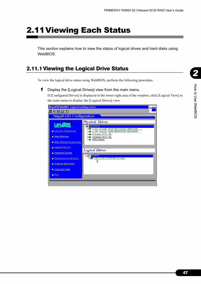
2.11Viewing Each Status
This section explains how to view the status of logical drives and hard disks using
WebBIOS.
2.11.1 Viewing the Logical Drive Status
To view the logical drive status using WebBIOS, perform the following procedure.
1 Display the [Logical Drives] view from the main menu.
If [Configured Drives] is displayed in the lower right area of the window, click [Logical View] in
the main menu to display the [Logical Drives] view.

48
Chapter 2 How to Use WebBIOS
2 Click the logical drive to be viewed from the [Logical Drives] area.
The status and the settings of the selected logical drive are displayed.
The following information is displayed in the [Properties] area.
• RAID level
• Logical drive status
• Logical drive size
• Stripe size
The logical drive status is as follows:
The current logical drive settings are displayed in the [Policies] area.
� The following 3 options displayed in the [Policies] area must be fixed to the values as shown
below without change:
Read → Normal
I/O → Direct
Virtual Size → Disabled
table: The logical drive status
Status Description
Optimal Online (normal)
Degraded Status without redundancy
Offline Offline (failed)

49
PRIMERGY RX600 S2 Onboard SCSI RAID User’s Guide
2
How
to U
se W
ebB
IOS
2.11.2 Viewing the Hard Disk Status
To view the hard disk status using WebBIOS, click the hard disk to be viewed from the [Physical Drives]
area in the main menu.
The following information is displayed in the [Properties] area.
• Size: Hard disk capacity
• State: Hard disk status
• SCSI Level: SCSI standard
p

50
Chapter 2 How to Use WebBIOS
The hard disk status is as follows.
The number of errors is displayed under [Health].
• Media Error: The number of media errors
• Non-Media Error: The number of other errors
• Predictive Failure: The number of predictive failures
� [SCSI-2 Command Tagging] must be fixed to "Enhanced QTag Scheduling" without change.
� Without instructions by our maintenance engineer, do not use the "Offline" function for a hard disk in
"Online" state.
� Without instructions by our maintenance engineer, do not use the "Online" function for a hard disk in
"Failed" state. Doing so may cause data loss.
table: The hard disk status
状態 説明
Online Online (normal)
Failed Offline (failed)
Rebuild Rebuild in progress
Ready Unused (available)
Hotspare Spare disk
Format Formatting

51
PRIMERGY RX600 S2 Onboard SCSI RAID User’s Guide
2
How
to U
se W
ebB
IOS
2.12Formatting a Hard Disk
This section explains how to perform a low level format on a hard disk using
WebBIOS.
When reusing a hard disk that has been used for another system, format the hard
disk according to the following procedure.
� When a hard disk is formatted, data on it is all deleted.
� Do not turn off or restart the server during formatting.
� Formatting of a hard disk can be executed only for hard disks in Ready state.
� Formatting of a hard disk takes time. Once started, it cannot be aborted. Perform it when you have
enough time.
� Multiple hard disks cannot be formatted simultaneously.
1 From the [Physical Drives] area in the main menu, click the hard disk in Ready
state to be formatted.
2 Select [Format] and click [Go].
3 Low level formatting of the hard disk starts.
Wait until the format is completed.
52
Chapter 2 How to Use WebBIOS
2.13Checking a Background Task in Progress
With WebBIOS, the status of a task currently running in the background can be
checked. This enables progress check of logical drive initialization, consistency
check, rebuild, etc.
While a task is being executed in the background, the task in progress is displayed at the bottom of the
main menu. Clicking buttons of each task enables progress check of the task being executed in the
background. The following tasks can be checked.
• Consistency check (Check Consistency Progress)
• Rebuild (Rebuild Progress)
• Initialization (Initialization Progress)
• Background initialization (Background Initialization Progress)
• Capacity expansion (Reconstruction Progress)
� Do not cancel background tasks in progress during normal use.
� The options such as Initialize/Check Consistency/Properties/Set Boot Drive displayed in the right side
of the window showing the progress of each task are not supported. Do not use these functions.
� If the button of the background task in progress is not displayed, it will be displayed by executing [Scan
Devices] from the main menu.

53
PRIMERGY RX600 S2 Onboard SCSI RAID User’s Guide
2
How
to U
se W
ebB
IOS
2.14Exiting WebBIOS
To exit WebBIOS, perform the following procedure.
1 Display the main menu.
2 Click [Exit].
3 When the message "Exit Application" appears, select [Yes].
4 When the message "Please Reboot your System" appears, the server can be
turned off.
5 Press the [Ctrl] + [Alt] + [Delete] keys to restart the server.

54
Chapter 2 How to Use WebBIOS

55
Chapter 3
Installing Global Array Manager (GAM)
This chapter explains how to install Global Array
Manager (GAM) to use a SCSI array controller in
a Windows Server 2003, Windows 2000 Server,
or Linux environment.
3.1 Overview / Product Requirements . . . . . . . . . . . . . . . . . . 56
3.2 Installing GAM . . . . . . . . . . . . . . . . . . . . . . . . . . . . . . . . . 58
3.3 Using GAM in a Linux Environment . . . . . . . . . . . . . . . . . 65
3.4 Using GAM in a Multiple Server Environment . . . . . . . . . . 66

56
Chapter 3 Installing Global Array Manager (GAM)
3.1 Overview / Product Requirements
This section explains Global Array Manager (hereafter referred to as GAM).
3.1.1 GAM Overview
Global Array Manager (GAM) is an application that allows you to manage a disk array system
connected to a SCSI array controller (RAID controller).
The functions of GAM are accomplished by the interaction of GAM Client with GAM Server.
• Monitoring function
GAM Server collects information about the status and resource usage of disk arrays and notices
them.
• Management function
GAM Client provides fault management, highly reliable messaging process, and excellent OS
support. GAM Client also manages maintenance of each disk array and hard disk and provides an
intuitive GUI.
� To ensure stable operation of PRIMERGY, install the GAM when using the onboard SCSI RAID.
The hard disk status cannot be monitored with the system operates when GAM is not installed. For
instance, the system down and the loss of data are caused due to leaving one hard disk breakdowns.
Install the GAM to detect malfunction at the stage where one hard disk breaks down.
3.1.2 Requirements for OS Drivers
The SCSI array controller setting must be configured in advance. When configuring the setting, refer to
"Chapter 2 How to Use WebBIOS" (�pg.19).
Make sure to complete the disk array setting as a preparation before installing the drivers and utilities as
described below.
Drivers and GAM must be installed with administrator privileges on each OS.
57
PRIMERGY RX600 S2 Onboard SCSI RAID User’s Guide
3
Insta
lling G
lobal A
rray M
anager (G
AM
)
3.1.3 Requirements for GAM
An appropriate server environment is required for using GAM Server and GAM Client properly. Use
hardware and software that meet the following conditions to create an environment best suited for use:
• OS: Windows Server 2003, Windows 2000 Server, Linux
• Hard disk free space: 20MB or more
• TCP/IP, SNMP service, and ServerView must be installed
� Apply the latest Service Pack to each OS.
� Make sure to install the specified drivers and GAM.
� Disk arrays are monitored by OS event logs that are noticed by ServerView. Because events that are
noticed from GAM (source: gamevlog) are not supported, ignore the events recorded by "gamevlog". If
any logs for a SCSI array controller are noticed by ServerView before or after the event, view the logs.
For the list of logs noticed by ServerView, refer to "Appendix B List of GAM Error Codes" (�pg.125).

58
Chapter 3 Installing Global Array Manager (GAM)
3.2 Installing GAM
This section explains how to install GAM. GAM must be installed for your safety.
� GAM cannot be overwrite-installed. Make sure to uninstall the existing GAM before reinstalling GAM.
� Depending on your system configuration, the SNMP service may be stopped after installing or
uninstalling GAM. Restart the OS after installing or uninstalling GAM.
� During GAM installation, you may be prompted to enter appropriate information. In such cases, follow
the window instructions to proceed.
3.2.1 How to Install GAM
Perform the following procedure to install GAM.
� To record events occurring to the OS event logs, install ServerView and configure the event logging
settings. For details, refer to "ServerView User Guide".
1 Log on with administrator privileges.
2 Before installing GAM, complete the following preparation:
• Check that TCP/IP is installed and working properly.
• Check that ServerView is installed and working properly.
• Insert the ServerStart CD-ROM into the CD-ROM drive.
• Exit all applications.
� Exit all applications before starting installation. Especially, if you install GAM while Event
Viewer or Computer Management is running, the installation may fail.
3 Click [Start] → [Run...]. Enter the following path and click [OK].
[CD-ROM drive name] :\PROGRAMS\GENERAL\LSI\GAM\install.bat
The Global Array Manager Setup wizard starts up.
4 In the [Welcome] window, click [Next].
The [Software License Agreement] window appears.

59
PRIMERGY RX600 S2 Onboard SCSI RAID User’s Guide
3
Insta
lling G
lobal A
rray M
anager (G
AM
)
5 Click [Yes].
The [Select Components] window appears.
Make sure the boxes next to [Global Array Manager Server] and [Global Array Manager Client]
are checked.
Uncheck [SANArray Manager Client].
� Do not install SANArray Manager Client because it is not supported.
6 Select [Global Array Manager Server] and click [Change].
The [Select Sub-components] window appears.
Make sure [Program Files] and [SNMP] are checked. If any items other than [Program Files] and
[SNMP] are displayed, uncheck them.
7 Click [Continue] after confirmation.
The [Select Components] window appears again.
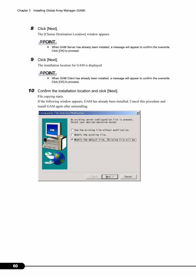
60
Chapter 3 Installing Global Array Manager (GAM)
8 Click [Next].
The [Choose Destination Location] window appears.
� When GAM Server has already been installed, a message will appear to confirm the overwrite.
Click [OK] to proceed.
9 Click [Next].
The installation location for GAM is displayed.
� When GAM Client has already been installed, a message will appear to confirm the overwrite.
Click [OK] to proceed.
10 Confirm the installation location and click [Next].
File copying starts.
If the following window appears, GAM has already been installed. Cancel this procedure and
install GAM again after uninstalling.

61
PRIMERGY RX600 S2 Onboard SCSI RAID User’s Guide
3
Insta
lling G
lobal A
rray M
anager (G
AM
)
11 Specify the client receiving events from GAM Server.
In the text box, enter the computer name on which GAM Client is being installed and click
[Next].
「The [Server Event Logging] window appears.
� If the IP address or computer name of Client is changed after GAM Server was installed,
events cannot be noticed correctly. In this case, GAM Server needs to be uninstalled first and
then installed again. (If the IP address is automatically obtained from the DHCP server, the IP
address may be changed depending on the timing of powering on/off or restarting the system.)
� To specify multiple clients receiving events, enter the computer names or IP addresses of serv-
ers, each separated by space. It is possible to specify up to 25 clients receiving events at a
time.
Make sure [Enable event logging on the server machine] is checked and click [Next].
12 Make sure [Enable event logging on the server machine] is checked and click
[Next].
� This option must be enabled.
13 When the full pathname of the configuration file appears, click [OK].
The [Setup Complete] window appears.
14 Click [Finish] to exit the GAM installation wizard.
15 Restart the system.
62
Chapter 3 Installing Global Array Manager (GAM)
16 Create the user account "gamroot" for GAM administrator privileges and a user
account for GAM user privileges (e.g. gamuser) as a Windows user account.
Assign the user account "gamroot" to the Administrators group.
� Create each user account as an OS user account.
� When creating the account for GAM administrator privileges, uncheck the following checkbox:
• [User must change password at next logon]
Also, check the following checkbox:
• [Password never expires]
If not making the above settings, you may not be able to log on to GAM.
3.2.2 Local Logon Setting on a Domain Controller
If Windows Server 2003 or Windows 2000 Server is used as a domain controller, it is necessary to set
the local logon rights to the user account with which you log on to GAM.
Configure the setting according to the following procedure.
� Attempting to log on to GAM with a user account that does not have the local logon rights will fail even
if the user name and password are entered correctly.
1 Click [Start] → [Programs] → [Administrative Tools] → [Domain Controller
Security Policy].
The [Domain Controller Security Policy] window appears.
2 Double-click [Security Settings].
3 Double-click [Local Policies].
4 Double-click [User Rights Assignment].
5 Double-click [Log on locally].
The [Security Policy Setting] window appears.
6 Click [Add].
7 Click [Browse].
8 Select the user account with which is to be logged on to GAM and click [Add].
9 Click [OK].
10 Click [OK].
The [Add User or Group] window closes.

63
PRIMERGY RX600 S2 Onboard SCSI RAID User’s Guide
3
Insta
lling G
lobal A
rray M
anager (G
AM
)
11 Click [OK].
The [Security Policy Setting] window closes.
12 Open [Command Prompt] and run the following command.
• For Windows Server 2003
• For Windows 2000 Server
3.2.3 How to Uninstall GAM
Perform the following procedure to uninstall GAM.
� Do not uninstall GAM Server/GAM Client during normal use.
■ Uninstalling GAM Client
1 Log on as Administrator.
2 Exit all programs before starting uninstallation.
If uninstalling GAM while Event Viewer or Computer Management is running, the uninstallation
will fail. Make sure to exit all programs.
3 Double-click [Add or Remove Applications] or [Add or Remove Programs].
4 Select [Mylex Global Array Manager Client v.n.nn-nn] from the application list
and click [Change/Remove].
The message "Are you sure you want to completely remove 'Mylex Global Array Manager Client
vn.nn-nn' and all of its components?" appears.
5 Click [Yes].
Uninstallation process starts.
6 When the uninstallation completes, click [OK].
■ Uninstalling GAM Server
1 Log on as Administrator.
2 Exit all programs before starting uninstallation.
If uninstalling GAM while Event Viewer or Computer Management is running, the uninstallation
will fail. Make sure to exit all programs.
C:\>gpupdate
C:\>secedit /refreshpolicy MACHINE_POLICY

64
Chapter 3 Installing Global Array Manager (GAM)
3 Click [Start] → [Settings] → [Control Panel] → [Add or Remove Applications].
4 Select [Mylex Global Array Manager Server v.n.nn-nn] from the application list
and click [Change/Remove].
The message "Are you sure you want to completely remove 'Mylex Global Array Manager
Server vn.nn-nn' and all of its components?" appears.
5 Click [Yes].
Uninstallation process starts.
6 When the uninstallation completes, click [OK].
7 Restart the system.

65
PRIMERGY RX600 S2 Onboard SCSI RAID User’s Guide
3
Insta
lling G
lobal A
rray M
anager (G
AM
)
3.3 Using GAM in a Linux Environment
To use GAM in a Linux environment, it is necessary to install device drivers and
GAM.
When using Linux on the server which has not bundled the Linux service, refer to the Fujitsu
PRIMERGY website (http://primergy.fujitsu.com).
� When GAM on a Linux server is monitored from GAM Client, GAM Client can only be installed on
servers or computers running Windows. Make considerations when creating system configuration
since GAM Client cannot be installed on a server running Linux.
The following figure shows a system configuration in which GAM Client on a Windows server manages
a Linux server.
� The following GAM Server and GAM Agent modules must be installed on the Linux server.
• gam-server-6.02-22.i386.rpm (GAM Server)
• gam-agent-6.02-22.i386.rpm (GAM Agent)
In addition, it is necessary to edit the configuration file to set the GAM event recipient and enable
storing event logs after the installation. For more details, refer to "Installation Guide" about Linux using
the above URL.
� If there is a firewall in the environment, it is necessary to configure network settings, such as disabling
blocking of the port used by the GAM protocol.
Windows server
GAM Client
GAM Server
GAM Agent
SCSI array controller
Monitor/configure
GAM status
Notify GAM event
Linux server

66
Chapter 3 Installing Global Array Manager (GAM)
3.4 Using GAM in a Multiple Server Environment
The following figure shows a system configuration in which GAM Client on the other
Windows server manages GAM Server.
� It is necessary to configure the server receiving GAM events during GAM installation. For more details,
refer to Step 12 in "3.2.1 How to Install GAM" (�pg.58).
� If there is a firewall in the environment, it is necessary to configure network settings, such as disabling
blocking of the port used by the GAM protocol.
3.4.1 Interaction between ServerView and AlarmService
The following figures show the interaction between AlarmService of ServerView and GAM Client on
the other Windows server manages GAM Server.
■ When Storing OS Event Logs on GAM Client
� ServerView must be installed on GAM Client.
� The OS event logs related to GAM events are stored on GAM Client.
GAM Client
GAM Server
GAM Agent
Windows server
Monitor/configure
GAM status
Windows server
Notify GAM event
SCSI array controller
GAM Client
GAM Server
GAM AgentServerView
AlarmService
OS event log
Windows server
Monitor/configure
GAM status
Windows server
SCSI array controller
Notify GAM event

67
PRIMERGY RX600 S2 Onboard SCSI RAID User’s Guide
3
Insta
lling G
lobal A
rray M
anager (G
AM
)
■ When Storing OS Event Logs on GAM Server
� ServerView must be installed on GAM Server.
� The OS event logs related to GAM events are stored on GAM Server.
GAM ClientGAM Server
GAM Agent
ServerViewAlarmService
Windows serverMonitor/configureGAM status
Windows server
Notify GAM event
OS event log
SCSI array controller

68
Chapter 3 Installing Global Array Manager (GAM)

69
Chapter 4
How to Use GAM
GAM is a basic utility to manage the disk array.
Read this chapter carefully before use.
4.1 Overview of GAM . . . . . . . . . . . . . . . . . . . . . . . . . . . . . . 70
4.2 Starting and Exiting GAM . . . . . . . . . . . . . . . . . . . . . . . . . 71
4.3 Window Layout . . . . . . . . . . . . . . . . . . . . . . . . . . . . . . . . 73
4.4 Settings . . . . . . . . . . . . . . . . . . . . . . . . . . . . . . . . . . . . . 80
4.5 Creating and Operating a RAID Configuration . . . . . . . . . 84
4.6 Viewing Information . . . . . . . . . . . . . . . . . . . . . . . . . . . . . 99
4.7 Maintenance Functions . . . . . . . . . . . . . . . . . . . . . . . . . . 111

70
Chapter 4 How to Use GAM
4.1 Overview of GAM
GAM is used for monitoring, management, maintenance and configuration of the
array controller, as well as hard disks and logical drives connected to it.
4.1.1 About the access privileges to GAM
It is necessary to log on (sign on) to GAM to use GAM functions: user authentication is made using the
user accounts registered in the OS. Note that available functions vary depending on the user account
used to log on (sign on). There are three access privileges as shown below:
■ GuestWhen using GAM with Guest privileges, it is not necessary to log on (sign on). With Guest privileges,
only the RAID status and occurring events can be checked. It is not possible to set or change parameters.
■ UserThis is mainly used to monitor the status of controllers and hard disks/logical drives. To use User
privileges, log on (sign on) with any of the user names and passwords registered in the OS. With User
privileges, in addition to using the functions made available with Guest privileges, several parameters
can be changed. It is also possible to view the detailed status of the controller and RAID subsystem
selected. Note that it is not possible to perform management such as changing a RAID configuration,
rebuilding drives, and changing parameters related to controllers and drivers.
� RAID configuration and data cannot be destroyed with User privileges. If GAM is used only for
purposes such as monitoring the RAID system or checking the status, it is recommended that using
User privileges.
■ AdministratorThis is used for management, maintenance and configuration of controllers and hard disks/logical
drives. To use Administrator privileges, log on (sign on) with "gamroot". In addition to the monitoring
functions made available with Guest or User privileges, it is possible to use all other functions including
creating/changing a RAID configuration, rebuilding drives, checking the consistency of logical drives,
and changing the drive status.
� When using GAM with Administrator privileges, depending on the operation, you may lose data in the
SCSI array controller. Read this Chapter and utilize GAM very carefully.
� If GAM information cannot be monitored from ServerView, there is a possibility that the network
settings are not proper. In this case, check the network settings again.
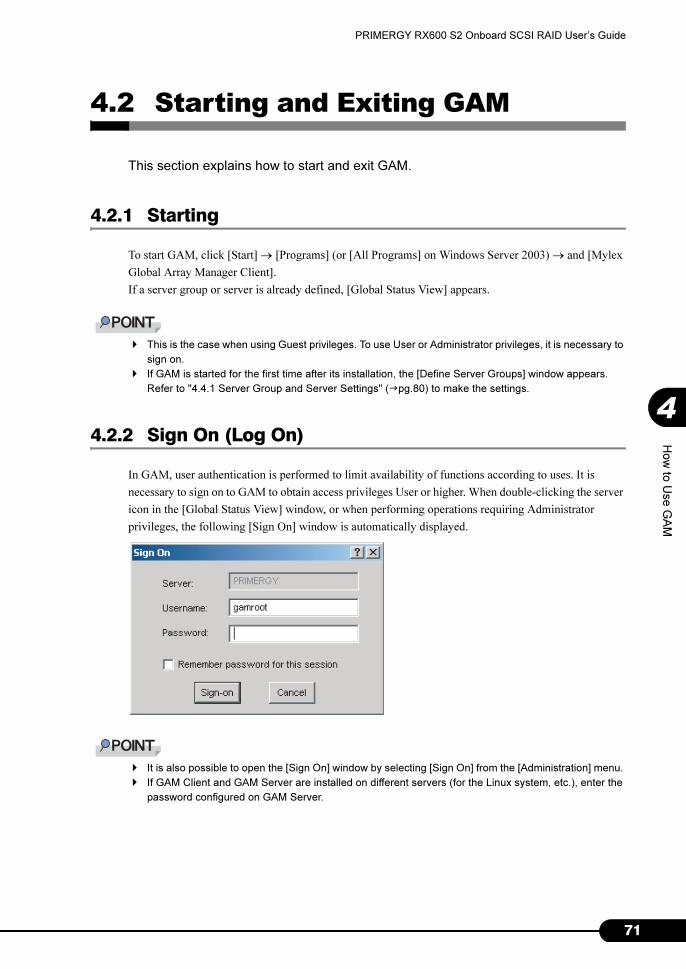
71
PRIMERGY RX600 S2 Onboard SCSI RAID User’s Guide
4
How
to U
se G
AM
4.2 Starting and Exiting GAM
This section explains how to start and exit GAM.
4.2.1 Starting
To start GAM, click [Start] → [Programs] (or [All Programs] on Windows Server 2003) → and [Mylex
Global Array Manager Client].
If a server group or server is already defined, [Global Status View] appears.
� This is the case when using Guest privileges. To use User or Administrator privileges, it is necessary to
sign on.
� If GAM is started for the first time after its installation, the [Define Server Groups] window appears.
Refer to "4.4.1 Server Group and Server Settings" (�pg.80) to make the settings.
4.2.2 Sign On (Log On)
In GAM, user authentication is performed to limit availability of functions according to uses. It is
necessary to sign on to GAM to obtain access privileges User or higher. When double-clicking the server
icon in the [Global Status View] window, or when performing operations requiring Administrator
privileges, the following [Sign On] window is automatically displayed.
� It is also possible to open the [Sign On] window by selecting [Sign On] from the [Administration] menu.
� If GAM Client and GAM Server are installed on different servers (for the Linux system, etc.), enter the
password configured on GAM Server.
72
Chapter 4 How to Use GAM
■ Procedure to sign on
Perform the following procedure to sign on.
1 Enter a user name.
• When signing on with User privileges
Enter any user name in [Username].
• When signing on with Administrator privileges
Enter "gamroot" in [Username].
2 Enter a password in [Password].
3 If [Remember password for this session] is checked, uncheck it.
� Note that if this option is checked, you can automatically sign on to different servers. To avoid
accessing servers automatically, it is recommended to keep this option unchecked.
4 Click [Sign-on].
� If Windows is used as a domain controller, it is necessary to set the local logon rights to the
user account used to sign on to GAM. If the local logon rights are not set, it is not possible to
sign on to GAM. Refer to "Chapter 3 Installing Global Array Manager (GAM)" (�pg.55).
� In GAM, availability of functions is limited according to access privileges. For access privileges,
refer to "4.1.1 About the access privileges to GAM" (�pg.70).
4.2.3 Exiting
To exit GAM, click [Exit] from [File] in the GAM menu bar.

73
PRIMERGY RX600 S2 Onboard SCSI RAID User’s Guide
4
How
to U
se G
AM
4.3 Window Layout
The following provides a description of windows, buttons, and menu items displayed
when using GAM.
4.3.1 Startup Window Layout/Functions
When GAM is started, a window consisting of [Global Status View] and [Log Information Viewer] will
appear.
■ Menu Bar
Allows you to perform GAM functions.
■ Tool Bar
Collection of buttons for frequently used functions on GAM.
■ Server Selection Box
Clicking ▼ displays a box listing the names of the server groups connected to the current client
workstation.
■ Global Status View
Displays servers in the currently selected server group.

74
Chapter 4 How to Use GAM
■ Controller Selection Box
Clicking ▼ displays the onboard SCSI array controller that connects to the currently selected server, or
the controller ID and type (e.g. MegaRAID SCSI 320-2E) of the SCSI array card.
■ Server Icon
Displays the server status. The following information is available:
• IP address (e.g. 10.1.19.100) or server name (e.g. ide40)
• Operating system running on the server (e.g. W2K3=Windows Server 2003, W2K=Windows 2000
Server)
• Server status (Green=normal, Yellow=critical, Red=failure or malfunction)
• Number and status of SCSI array controllers connected to the server (Green=normal, Yellow=critical,
Red=failure or malfunction)
■ Log Information Viewer
Displays an event that occurred.
table: Log Information Viewer
Event Details
Event ID Displays the level of an event to be reported using an icon that signifies information, caution,
warning, or others. Displays simultaneously the ID assigned to the event being reported.
Severity Priority level of the event.
Source IP address or name of the server that sent the event.
Source Time Time when the event occurred.
Device Address Other data regarding the channels linked, operations in question, and reason why this event
was sent.
Description Description of the event.
Sequence(Seq) Sequence number of the event.
Local Time Time when the event occurrence was signaled to GAM Client.
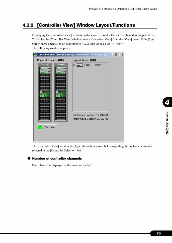
75
PRIMERGY RX600 S2 Onboard SCSI RAID User’s Guide
4
How
to U
se G
AM
4.3.2 [Controller View] Window Layout/Functions
Displaying the [Controller View] window enables you to monitor the status of hard disks/logical drives.
To display the [Controller View] window, select [Controller View] from the [View] menu. If the [Sign
On] window opens, sign on according to "4.2.2 Sign On (Log On)" (�pg.71).
The following window appears.
The [Controller View] window displays information shown below regarding the controller currently
selected in the [Controller Selection] box.
● Number of controller channels
Each channel is displayed as the tower on the left.

76
Chapter 4 How to Use GAM
● Hard disk
Displays the target ID, device capacity, device type and device status. The following shows the hard disk
status:
● Logical drive
Displays the logical drive number and capacity, RAID level set, and logical drive status. The following
shows the logical drive status:
● Enclosure
This function is not supported.
Double-clicking the icon of each hard disk/logical drive enables you to display more detailed
information. For more details, refer to "4.6 Viewing Information" (�pg.99).
table: Hard disk status icon
Icon Color Status
Green Normal (OnLine)
Red Failure (Dead)
Yellow Rebuild in progress (Rebuilding)
Green + white Spare drive (Hot Spare)
Yellow Failure expected (Critical)
State of PFA Count not 0
Not applied Unused and available (Unconfigured)
table: Logical drive status icon
Icon Color Status
Green Normal (OnLine)
Yellow Operating without redundancy (Critical)
Red Cannot be used (OffLine)
Green Checking consistency

77
PRIMERGY RX600 S2 Onboard SCSI RAID User’s Guide
4
How
to U
se G
AM
4.3.3 Menu Layout/Functions
The following explains the function of each menu item.
■ [File] Menu
� It is necessary to open [Controller View] to use the above menus.
� If [Open Configuration] or [Clear Configuration] is executed, all the existing array configurations and
data on the logical drives will be deleted. Do not perform the above operations unless directed by your
maintenance engineer.
■ [View] Menu
table: [File] Menu
Menu Function
Open Configuration Reads the disk array settings saved in the disk in advance and reflects these to the currently
selected controller. For more details, refer to "4.5.8 Saving, Restoring and Deleting RAID
Configuration Information" (�pg.97).
Save Configuration Saves the current RAID configuration in a file. For more details, refer to "4.5.8 Saving,
Restoring and Deleting RAID Configuration Information" (�pg.97).
Clear Configuration Clears all the RAID configurations of the currently selected SCSI array controller. For
more details, refer to "4.5.8 Saving, Restoring and Deleting RAID Configuration
Information" (�pg.97).
table: [View] Menu
Menu Function
Global Status View Displays the [Global Status View] window. By default, [Global Status View] is configured
to open at the time of GAM startup.
Controller View Displays the [Controller View] window. This window displays information of each device,
or displays the status of hard disks or logical drives connected to the controller selected in
the controller selection box.
Log Information
Viewer
Displays the [Log Information Viewer] window. This window displays events or errors
that occurred in the SCSI array controller. [Log Information Viewer] opens automatically
when GAM Client starts up.
Foreground
Initialize Status
Displays progress of on-going foreground initialization of a logical drive. This is selectable
only while foreground initialization is in progress.
Background
Initialize Status
Displays progress of the on-going background initialization of a logical drive. This is
selectable only while background initialization is in progress.
Rebuild Status Displays progress of the on-going rebuild. This is selectable only while a rebuild is in
progress.
Consistency Check
Status
Displays progress of the on-going consistency check. This is selectable only while
consistency check is in progress.
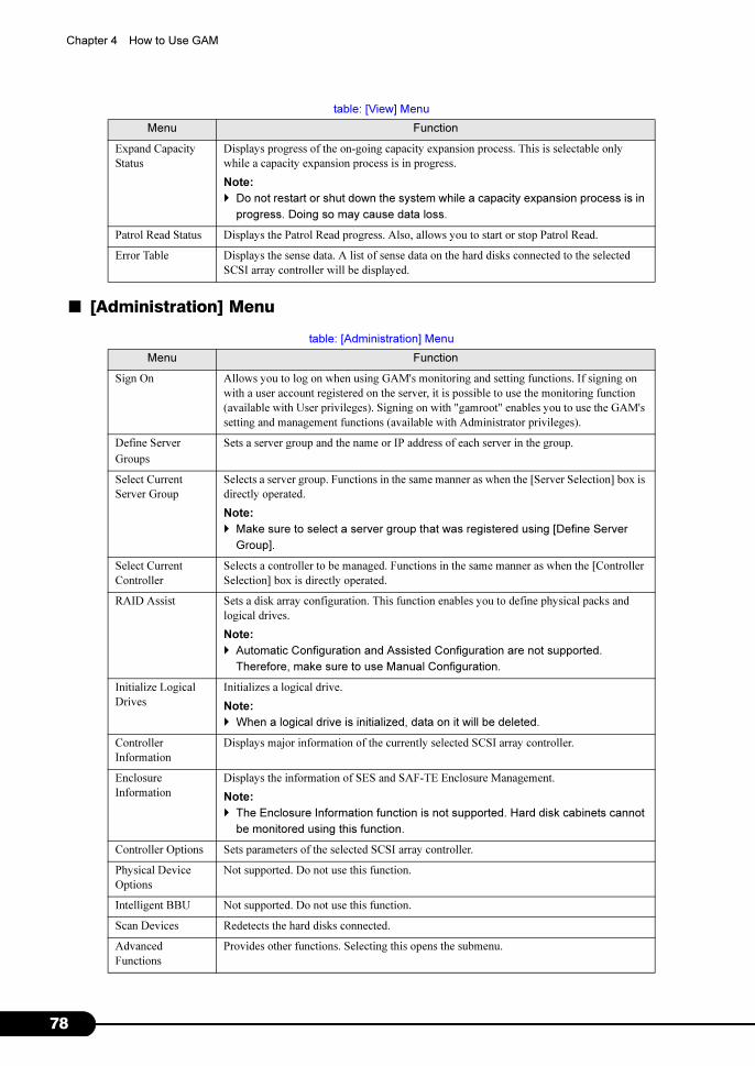
78
Chapter 4 How to Use GAM
■ [Administration] Menu
Expand Capacity
Status
Displays progress of the on-going capacity expansion process. This is selectable only
while a capacity expansion process is in progress.
Note:
� Do not restart or shut down the system while a capacity expansion process is in
progress. Doing so may cause data loss.
Patrol Read Status Displays the Patrol Read progress. Also, allows you to start or stop Patrol Read.
Error Table Displays the sense data. A list of sense data on the hard disks connected to the selected
SCSI array controller will be displayed.
table: [Administration] Menu
Menu Function
Sign On Allows you to log on when using GAM's monitoring and setting functions. If signing on
with a user account registered on the server, it is possible to use the monitoring function
(available with User privileges). Signing on with "gamroot" enables you to use the GAM's
setting and management functions (available with Administrator privileges).
Define Server
Groups
Sets a server group and the name or IP address of each server in the group.
Select Current
Server Group
Selects a server group. Functions in the same manner as when the [Server Selection] box is
directly operated.
Note:
� Make sure to select a server group that was registered using [Define Server
Group].
Select Current
Controller
Selects a controller to be managed. Functions in the same manner as when the [Controller
Selection] box is directly operated.
RAID Assist Sets a disk array configuration. This function enables you to define physical packs and
logical drives.
Note:
� Automatic Configuration and Assisted Configuration are not supported.
Therefore, make sure to use Manual Configuration.
Initialize Logical
Drives
Initializes a logical drive.
Note:
� When a logical drive is initialized, data on it will be deleted.
Controller
Information
Displays major information of the currently selected SCSI array controller.
Enclosure
Information
Displays the information of SES and SAF-TE Enclosure Management.
Note:
� The Enclosure Information function is not supported. Hard disk cabinets cannot
be monitored using this function.
Controller Options Sets parameters of the selected SCSI array controller.
Physical Device
Options
Not supported. Do not use this function.
Intelligent BBU Not supported. Do not use this function.
Scan Devices Redetects the hard disks connected.
Advanced
Functions
Provides other functions. Selecting this opens the submenu.
table: [View] Menu
Menu Function

79
PRIMERGY RX600 S2 Onboard SCSI RAID User’s Guide
4
How
to U
se G
AM
4.3.4 Tool Bar Icons
Tool bar icons at the top of the [Global Array Manager] window enable you to start up frequently used
functions.
Flash Utility Not supported. Do not use this function.
Settings Not supported. Do not use this function.
Alarm Sound Not supported. Do not use this function.
Consistency Check
with Restoration
Specifies whether data should be corrected or not during a consistency check. If set to
Enable, data will be corrected in the event it lacks consistency.
table: Tool bar Icons
Icon Function
Displays the [RAID Assist] window and starts creating a RAID configuration. Functions in the same
manner as when [RAID Assist] is selected from the [Administration] menu.
Rescans the devices. Functions in the same manner as when [Scan Devices] is executed from the
[Administration] menu.
Displays controller information. Functions in the same manner as when [Controller Information] is
selected from the [Administration] menu.
Displays sense data. Functions in the same manner as when [Error Table] is selected from the [View]
menu.
Displays the [Sign On] window. Functions in the same manner as when [Sign On] is selected from
the [Administration] menu.
This function is not supported.
Displays Help.
table: [Administration] Menu
Menu Function
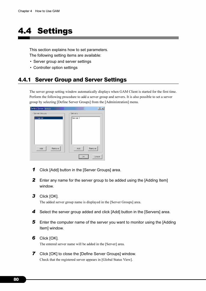
80
Chapter 4 How to Use GAM
4.4 Settings
This section explains how to set parameters.
The following setting items are available:
• Server group and server settings
• Controller option settings
4.4.1 Server Group and Server Settings
The server group setting window automatically displays when GAM Client is started for the first time.
Perform the following procedure to add a server group and servers. It is also possible to set a server
group by selecting [Define Server Groups] from the [Administration] menu.
1 Click [Add] button in the [Server Groups] area.
2 Enter any name for the server group to be added using the [Adding Item]
window.
3 Click [OK].
The added server group name is displayed in the [Server Groups] area.
4 Select the server group added and click [Add] button in the [Servers] area.
5 Enter the computer name of the server you want to monitor using the [Adding
Item] window.
6 Click [OK].
The entered server name will be added in the [Server] area.
7 Click [OK] to close the [Define Server Groups] window.
Check that the registered server appears in [Global Status View].

81
PRIMERGY RX600 S2 Onboard SCSI RAID User’s Guide
4
How
to U
se G
AM
4.4.2 Setting and Changing Controller Options
It is possible to check and change SCSI array controller options from [Controller Options] in the
[Administration] menu. The properties of the SCSI array controller need to be configured as follows.
However, [Rate] for [Enable Automatic Rebuild Management] can be changed.
� If settings are made improperly, correct operation may not be ensured. Make sure to check the
settings.
� If you temporarily change Rebuild Rate or Consistency Check Rate at the time of hard disk
replacement or consistency check, make sure to restore its value after finishing the task.
� For Background Initialization and Check Consistency, their rates cannot be specified independently.
Because operation is ensured by synchronizing the above rates with the setting for Automatic Rebuild
Management, make sure to change the rate set for Automatic Rebuild Management when specifying
the rates for Background Initialization and Check Consistency.
table: Properties of the SCSI array controller
Option type Parameter Setting
Global Parameters Enable Automatic Rebuild Management Enable
Rate 50
Enable Background Initialization Enable (Fixed)
Rate 0 (Fixed)
Check Consistency Rate 50
MORE Rate 0 (Fixed)
Enable Auto Drive Sizing Enable (Fixed)
Startup Parameters Disk Spin-up On Command (Fixed)
Devices Per Spins 2
Initial Delay 5 (Fixed)
Delay Between Spins 6
Clustering Parameters Enable Clustering Disable (Fixed)
Controller Host ID 7 (Fixed)
Advanced Temporarily Offline RAID Array Enabled
Device Health Monitoring(S.M.A.R.T/I.E.C) Enabled
Polling Interval 5
Patrol Read Enabled
Delay between Iterations 168

82
Chapter 4 How to Use GAM
4.4.3 Controller Options Window Layout/Functions
Open the [Controller Options] window from the [Administration] menu (�pg.78).
■ Global Parameters
• Enable Automatic Rebuild Management
Working with SAF-TE Disk Array Enclosure, detects a failed hard disk and automatically executes
the rebuild process after a new hard disk is installed. Sets the priority of rebuilding using [Rate].
Increasing the value performs the rebuild at a higher speed. Decreasing the value performs the
rebuild at a lower speed.
• Enable Background Initialization
Enables the background initialization function. This function is constantly enabled. This setting
cannot be changed.
• Check Consistency Rate
Sets the priority of a consistency check. Increasing the value in [Rate] performs consistency check at
a higher speed. Decreasing the value performs consistency check at a lower speed.

83
PRIMERGY RX600 S2 Onboard SCSI RAID User’s Guide
4
How
to U
se G
AM
• MORE Rate
Not supported.
• Enable Auto Drive Sizing
Automatically adjusts the size displayed for the hard disk capacity. This function is constantly
enabled. This option cannot be changed.
■ Start up Parameters
• Disk Spin-up
Sets how the hard disks start rotating. Fixed to "On Command".
• Devices per Spins
Sets the number of hard disks that start rotating at the same time. The smaller the number, the lighter
the loads on the power supply.
• Initial Delay
Fixed to 5 seconds. Cannot be changed.
• Delay Between Spins
Specifies the cycle of rotation start between hard disks that rotate in sequence.
■ Clustering Parameters (Specifying Clustering-related Parameters)
Not supported.
■ Advanced Options
• Temporarily Offline RAID Array
Of hard disks composing the array, if multiple hard disks become "Offline", treats the second or later
hard disks that become Offline as "temporarily Offline", changes their status to "Online" at the time
of the next system startup, and sets the status of the array to "Critical".
• Device Health Monitoring (S.M.A.R.T/I.E.C)
Enables the hard disk failure prediction function. Specifies a polling interval for S.M.A.R.T detection
at [Polling Interval].
• Patrol Read
If [Start Automatically on Start Up] is enabled, the Patrol Read function is automatically executed
when the system starts up. Specifies an interval of Patrol Read execution at [Delay between
Iterations]. The value is set by specifying a multiple of 4 between 0 and 1016.
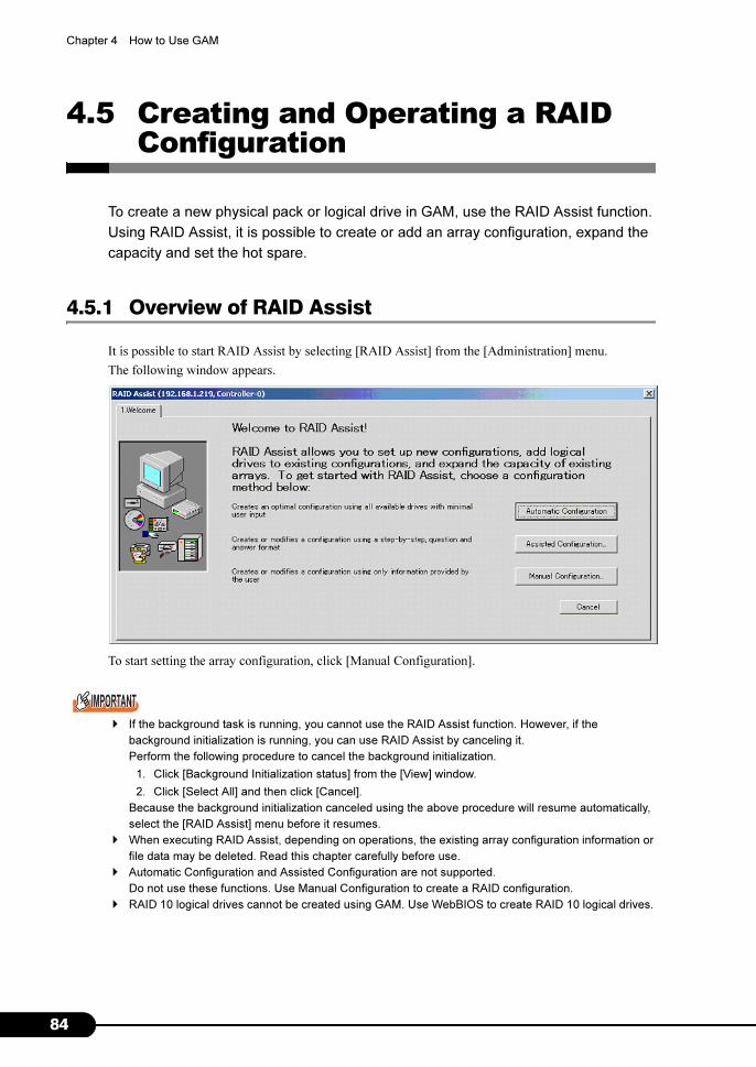
84
Chapter 4 How to Use GAM
4.5 Creating and Operating a RAID Configuration
To create a new physical pack or logical drive in GAM, use the RAID Assist function.
Using RAID Assist, it is possible to create or add an array configuration, expand the
capacity and set the hot spare.
4.5.1 Overview of RAID Assist
It is possible to start RAID Assist by selecting [RAID Assist] from the [Administration] menu.
The following window appears.
To start setting the array configuration, click [Manual Configuration].
� If the background task is running, you cannot use the RAID Assist function. However, if the
background initialization is running, you can use RAID Assist by canceling it.
Perform the following procedure to cancel the background initialization.
1. Click [Background Initialization status] from the [View] window.
2. Click [Select All] and then click [Cancel].
Because the background initialization canceled using the above procedure will resume automatically,
select the [RAID Assist] menu before it resumes.
� When executing RAID Assist, depending on operations, the existing array configuration information or
file data may be deleted. Read this chapter carefully before use.
� Automatic Configuration and Assisted Configuration are not supported.
Do not use these functions. Use Manual Configuration to create a RAID configuration.
� RAID 10 logical drives cannot be created using GAM. Use WebBIOS to create RAID 10 logical drives.

85
PRIMERGY RX600 S2 Onboard SCSI RAID User’s Guide
4
How
to U
se G
AM
The following window appears.
The buttons are used in the following situations.
■ Edit Configuration
Used for setting/releasing a hot spare disk or for deleting a logical drive.
� Do not use Edit Configuration for purposes other than to delete a logical drive or to set/release a hot
spare.
� When a logical drive is deleted, the data inside is also deleted. Thus, full planning is absolutely
required before using this function.
■ New Configuration
Deletes the old array configuration and data (if any) and applies a new array configuration to the SCSI
array controller. This function is used when no array configuration exists on the SCSI array controller, or
when a new array configuration is created after deleting the existing array configuration completely.
� Executing New Configuration deletes the existing configuration information. Use this function very
carefully since it will delete all the existing logical drives and data inside.
■ Add Logical Drive
Used for setting up an additional logical drive while keeping the existing array configuration as is. It is
necessary that one or more logical drives are set for the selected SCSI array controller, and that free
space remains in the physical pack or hard disks that are unused (Unconfigured).
■ Expand Array
To expand the logical drive's capacity, adds an unused (Unconfigured) hard disk to an existing physical
pack and reconfigure data in the drive. The data in the logical drive to be expanded will not be
destroyed.

86
Chapter 4 How to Use GAM
4.5.2 Creating a New RAID Configuration (New Configuration)
To newly create an array configuration or to create a new array configuration after deleting the existing
array configuration completely, perform the following procedure.
The following shows a procedure for executing New Configuration.
1 Start [RAID Assist] from the [Administration] menu.
�"4.5.1 Overview of RAID Assist" (pg.84)
2 Click [Manual Configuration].
3 Click [New Configuration].
The following window appears. At this point, create a physical pack.
The physical pack is displayed in the [Disk Arrays] area at the top left of the window.
A list of unused hard disks is displayed in the [Unused Disk Drives] area at the bottom left of the
window. Select an unused hard disk from the above list and drag and drop it to the [Disk Array
A0] area. The hard disk dragged and dropped will become part of the physical pack A0. A
maximum of 5 hard disks can be added to one physical pack.
� When you select unused hard disks, selecting while holding down the [Ctrl] key enables selec-
tion of multiple hard disks at a time.
In addition, drag and drop hard disks from the [Disk Arrays] area into the [Unused Disk Drives]
area to delete them from a physical pack.
Click [Clear All] if you want to make a physical pack setting from the beginning.
� At this point, do not use the [Add Array]. When multiple physical packs are created, use [Add
Logical Drive] after completing this procedure and make an addition.
� Use hard disks of the same capacity and type in one physical pack. If a mixture of different
hard disks are connected, check in advance according to "4.6.3 Viewing Hard Disk
Information" (�pg.103).

87
PRIMERGY RX600 S2 Onboard SCSI RAID User’s Guide
4
How
to U
se G
AM
4 When a spare disk is set, click [Make Spare] with the unused hard disk
selected.
The unused hard disk icon will be changed to a spare disk icon. To release a spare disk, select the
spare disk to be released and then click [Remove Spare].
� Do not drag and drop a hard disk whose status was set as a spare disk into the physical pack
area.
� Use a spare disk of the same capacity and type as hard disks in the physical pack.
� If a spare disk is set when multiple physical packs that use different hard disks exist, a spare
disk must be set for each type of hard disks.
5 Click the [Logical Drives] tab after creating the physical pack, and start setting
up a logical drive.
6 Select a RAID level to set for the logical drive.
Click ▼ of [RAID Level] and then select the RAID level to set for the logical drive from the list
displayed.
� RAID 10 logical drives cannot be created using GAM. Use WebBIOS to create RAID 10 logical
drives.
7 Enter the capacity of a logical drive to be created in [Capacity-Logical] or the
physical capacity to be used in [Capacity-Physical].
If only one logical drive is created in the disk array, or if the last logical drive in the physical pack
is created, do not change the default size. If creating multiple logical drives, enter a value smaller
than the entire capacity to leave the required capacity.
� The capacity of a logical drive may be adjusted to match the block size.
� It is recommended not to create multiple logical drives in a single physical pack.
If multiple logical drives are created in a single physical pack, it is not possible to expand the
capacity later using the [Expand Capacity] function.

88
Chapter 4 How to Use GAM
8 To initialize a logical drive that is created after creating the configuration, check
the [Init Drive] checkbox.
� Even if this option is not checked, the background initialization will be performed automatically.
9 Select [64KB] for the Stripe Size.
� [Stripe Size] must be set to [64KB].
10 Click [Add Drive] to register the new logical drive.
11 To create multiple logical drives in a single physical pack, repeat Steps 6
through 10 respectively.
� Do not set logical drives of different RAID levels in a single physical pack.
� Do not leave free space in the physical pack. (Do not change the capacity of the last created
logical drive in Step 7. In addition, check that "0" appears in the [Capacity] fields for both Logi-
cal and Physical after the last logical drive has been added.)
� Do not check the [Write Cache] checkbox.
12 After completing setup of all the logical drives, click [Apply] to enable the
configuration.
13 A final confirmation window appears. Enter "YES" and click [OK].
If a logical drive exists whose [Init Drive] has been checked in Step 8, the following window
displayed.
Click [YES] to perform foreground initialization, or click [No] to perform background
initialization.
� This window appears asking whether the redundant logical drive with [Init Drive] checked
should be initialized in the foreground or background.
This window does not appear for logical drives with [Init Drive] not checked.
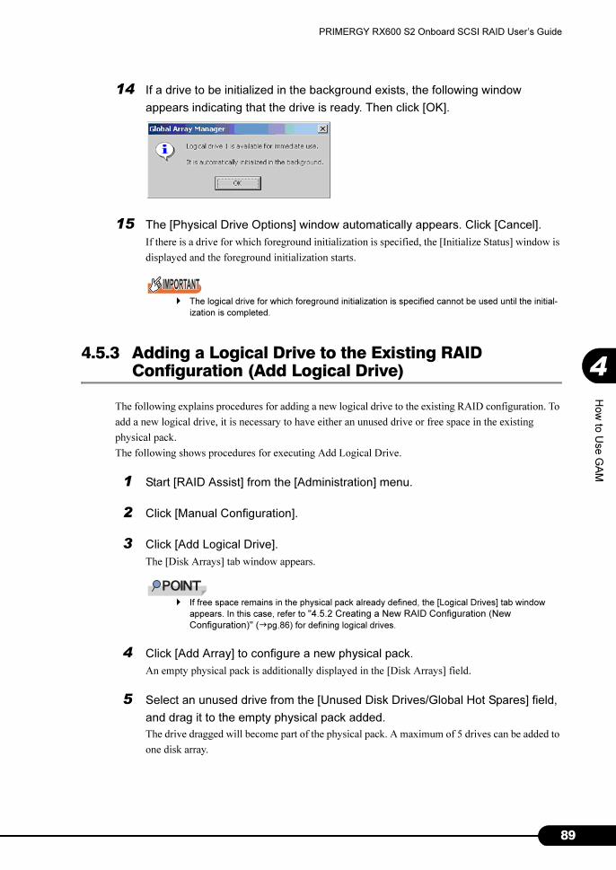
89
PRIMERGY RX600 S2 Onboard SCSI RAID User’s Guide
4
How
to U
se G
AM
14 If a drive to be initialized in the background exists, the following window
appears indicating that the drive is ready. Then click [OK].
15 The [Physical Drive Options] window automatically appears. Click [Cancel].
If there is a drive for which foreground initialization is specified, the [Initialize Status] window is
displayed and the foreground initialization starts.
� The logical drive for which foreground initialization is specified cannot be used until the initial-
ization is completed.
4.5.3 Adding a Logical Drive to the Existing RAID Configuration (Add Logical Drive)
The following explains procedures for adding a new logical drive to the existing RAID configuration. To
add a new logical drive, it is necessary to have either an unused drive or free space in the existing
physical pack.
The following shows procedures for executing Add Logical Drive.
1 Start [RAID Assist] from the [Administration] menu.
2 Click [Manual Configuration].
3 Click [Add Logical Drive].
The [Disk Arrays] tab window appears.
� If free space remains in the physical pack already defined, the [Logical Drives] tab window
appears. In this case, refer to "4.5.2 Creating a New RAID Configuration (New
Configuration)" (�pg.86) for defining logical drives.
4 Click [Add Array] to configure a new physical pack.
An empty physical pack is additionally displayed in the [Disk Arrays] field.
5 Select an unused drive from the [Unused Disk Drives/Global Hot Spares] field,
and drag it to the empty physical pack added.
The drive dragged will become part of the physical pack. A maximum of 5 drives can be added to
one disk array.
90
Chapter 4 How to Use GAM
� Do not add multiple disk arrays at a time. If an additional disk array is created, complete this
procedure, apply the configuration and execute Add Logical Drive again.
� Use hard disks of the same capacity and type in one physical pack. If a mixture of different
hard disks are connected, check in advance according to "4.6.3 Viewing Hard Disk
Information" (�pg.103).
6 When a spare disk is set, click [Make Spare] with the unused hard disk
selected.
The unused hard disk icon will be changed to a spare disk icon. To release a spare disk, select the
spare disk to be released and then click [Remove Spare].
� Please advance to the following procedure (procedure 7) after clicking [Make Spare] or
[Remove Spare] without fail only even when the spare disk is set.
A set content is not reflected as long as the content of procedure 7 is not executed.
� Do not drag and drop a hard disk whose status was set as a spare disk into the physical pack
area.
� Use a spare disk of the same capacity and type as hard disks in the physical pack.
� If a spare disk is set when multiple physical packs that use different hard disks exist, a spare
disk must be set for each type of hard disk.
7 Click the [Logical Drives] tab after configuring the physical pack and spare disk,
and start setting up a logical drive.
After this, refer to Steps 6 and later in "4.5.2 Creating a New RAID Configuration (New Configuration)"
(�pg.86) for defining logical drives.
4.5.4 Expanding Capacity of a Logical Drive (Expand Array)
The capacity of a logical drive can be expanded by adding a new hard disk at a later time to the existing
physical pack. To expand the capacity of a logical drive, the target logical drive needs to satisfy the
following conditions:
• Only one logical drive must be defined in the physical pack.
• The number of hard disks that compose the target physical pack/logical drive must not exceed 5 after
capacity expansion.
• The RAID level of the target logical drive must be 1, or 5. (Capacity expansion is not possible for
RAID 10.)
• The OS must be Windows 2000 Server or Windows Server 2003.

91
PRIMERGY RX600 S2 Onboard SCSI RAID User’s Guide
4
How
to U
se G
AM
1 To prepare for unexpected problems, perform data backup.
2 Perform consistency check onto the logical drive whose capacity is to be
expanded.
Confirm that the check completes successfully.
� If it does not complete successfully, do not perform capacity expansion.
3 Start [RAID Assist] from the [Administration] menu.
4 Click [Manual Configuration].
5 Click [Expand Array].
The following window appears. Select a logical drive to be expanded.
6 Click [OK].
The [Disk Arrays] tab window appears.

92
Chapter 4 How to Use GAM
7 Select an unused hard disk from the [Unused Disk Drives] area and drag and
drop it to the physical pack displayed at the top left of the window.
You can add hard disks until the total number of hard disks in the physical pack reaches 5.
� Keep the number of hard disks in the physical pack 5 or less.
� Use additional hard disks of the same capacity and type as the hard disks in the physical pack.
If a mixture of different hard disks are connected, check in advance according to "4.6.3
Viewing Hard Disk Information" (�pg.103).
8 Click the [Logical Drives] tab after adding a hard disk to the physical pack.
9 Select [RAID Level].
After the expansion, the RAID level of the logical drive will be converted to the RAID level
selected here. RAID 5 can be selected.
� Do not change Stripe Size.
� RAID 0 is not supported. Please do not select RAID 0.
10 Click [Apply].
When the following confirmation window appears, click [YES].
11 A final confirmation window appears.
Enter "YES" and click [OK].
A window showing the progress of capacity expansion appears and the expansion process starts. Wait
until the process is completed.
� While capacity expansion is in progress, do not turn off, reset or restart the server. Doing so may cause
loss of data on the target logical drive.
� If the server is turned off during the capacity expansion process, access to the hard disk resumes
automatically after the server restart. In this case, wait until the access lamp on the hard disk turned
off, ensure that no access is made to the hard disk, create an array configuration again and then
restore the data backed up before the task.
� If the RAID level of the logical drive after expansion is RAID 5, background initialization will be
performed after capacity expansion completes.
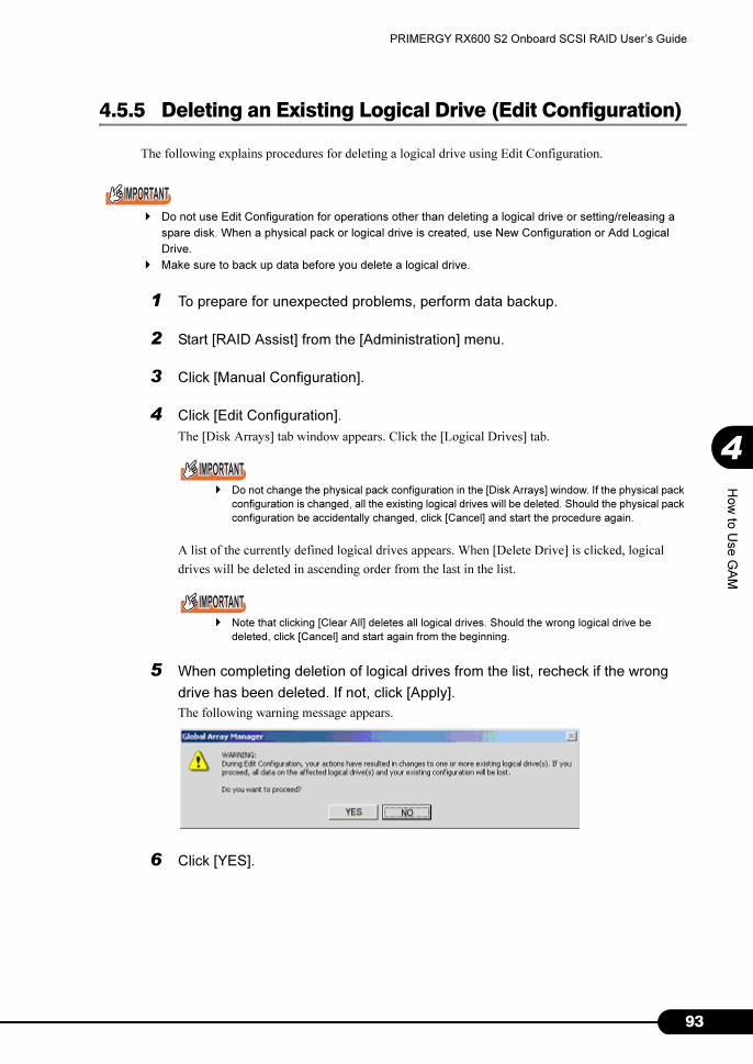
93
PRIMERGY RX600 S2 Onboard SCSI RAID User’s Guide
4
How
to U
se G
AM
4.5.5 Deleting an Existing Logical Drive (Edit Configuration)
The following explains procedures for deleting a logical drive using Edit Configuration.
� Do not use Edit Configuration for operations other than deleting a logical drive or setting/releasing a
spare disk. When a physical pack or logical drive is created, use New Configuration or Add Logical
Drive.
� Make sure to back up data before you delete a logical drive.
1 To prepare for unexpected problems, perform data backup.
2 Start [RAID Assist] from the [Administration] menu.
3 Click [Manual Configuration].
4 Click [Edit Configuration].
The [Disk Arrays] tab window appears. Click the [Logical Drives] tab.
� Do not change the physical pack configuration in the [Disk Arrays] window. If the physical pack
configuration is changed, all the existing logical drives will be deleted. Should the physical pack
configuration be accidentally changed, click [Cancel] and start the procedure again.
A list of the currently defined logical drives appears. When [Delete Drive] is clicked, logical
drives will be deleted in ascending order from the last in the list.
� Note that clicking [Clear All] deletes all logical drives. Should the wrong logical drive be
deleted, click [Cancel] and start again from the beginning.
5 When completing deletion of logical drives from the list, recheck if the wrong
drive has been deleted. If not, click [Apply].
The following warning message appears.
6 Click [YES].

94
Chapter 4 How to Use GAM
7 A final confirmation message appears. Enter "YES" and click [OK].
8 Click [Cancel] when the [Physical Device Options] window appears.
� Should the wrong logical drive be deleted, create an array configuration again and then restore
the data backed up before the task.
� If all logical drives in a physical pack are deleted, the physical pack will be automatically
deleted, and the hard disks that composed the physical pack will become unused.
4.5.6 Setting and Releasing a Spare Disk (Edit Configuration)
This section explains how to set and release a spare disk.
� Do not use Edit Configuration for operations other than deleting a logical drive or setting/releasing a
spare disk. When a physical pack or logical drive is created, use New Configuration or Add Logical
Drive.
1 Start [RAID Assist] from the [Administration] menu.
2 Click [Manual Configuration].
3 Click [Edit Configuration].
The [Disk Arrays] tab window appears.
4 Click [Make Spare] with the unused hard disk selected in the [Unused Disk
Drives] area.
The unused hard disk icon will be changed to a spare disk icon. To release a spare disk, select its
icon and then click [Remove Spare].
� If a physical pack exists that consists of hard disks with capacity larger than that of a hard disk
to set as a spare, the following message appears when [Make Spare] is clicked. Click [OK].
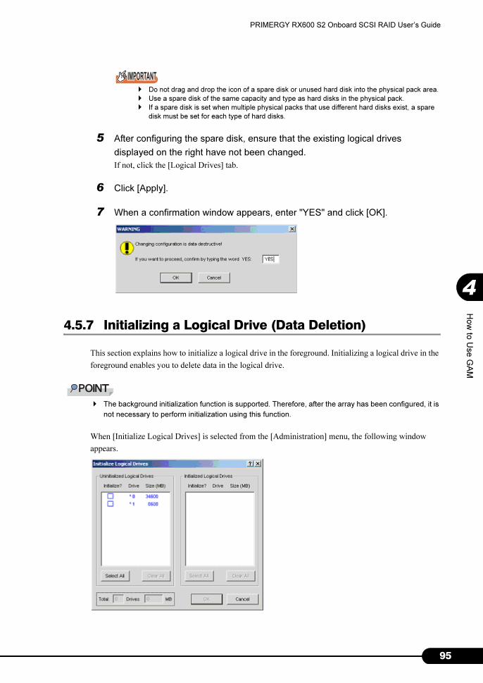
95
PRIMERGY RX600 S2 Onboard SCSI RAID User’s Guide
4
How
to U
se G
AM
� Do not drag and drop the icon of a spare disk or unused hard disk into the physical pack area.
� Use a spare disk of the same capacity and type as hard disks in the physical pack.
� If a spare disk is set when multiple physical packs that use different hard disks exist, a spare
disk must be set for each type of hard disks.
5 After configuring the spare disk, ensure that the existing logical drives
displayed on the right have not been changed.
If not, click the [Logical Drives] tab.
6 Click [Apply].
7 When a confirmation window appears, enter "YES" and click [OK].
4.5.7 Initializing a Logical Drive (Data Deletion)
This section explains how to initialize a logical drive in the foreground. Initializing a logical drive in the
foreground enables you to delete data in the logical drive.
� The background initialization function is supported. Therefore, after the array has been configured, it is
not necessary to perform initialization using this function.
When [Initialize Logical Drives] is selected from the [Administration] menu, the following window
appears.
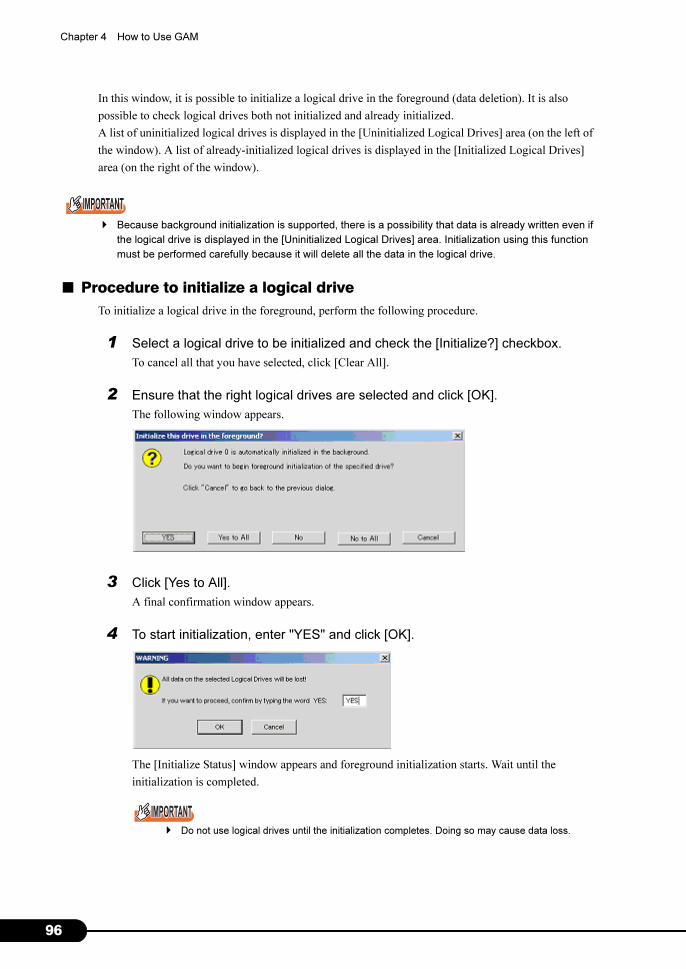
96
Chapter 4 How to Use GAM
In this window, it is possible to initialize a logical drive in the foreground (data deletion). It is also
possible to check logical drives both not initialized and already initialized.
A list of uninitialized logical drives is displayed in the [Uninitialized Logical Drives] area (on the left of
the window). A list of already-initialized logical drives is displayed in the [Initialized Logical Drives]
area (on the right of the window).
� Because background initialization is supported, there is a possibility that data is already written even if
the logical drive is displayed in the [Uninitialized Logical Drives] area. Initialization using this function
must be performed carefully because it will delete all the data in the logical drive.
■ Procedure to initialize a logical drive
To initialize a logical drive in the foreground, perform the following procedure.
1 Select a logical drive to be initialized and check the [Initialize?] checkbox.
To cancel all that you have selected, click [Clear All].
2 Ensure that the right logical drives are selected and click [OK].
The following window appears.
3 Click [Yes to All].
A final confirmation window appears.
4 To start initialization, enter "YES" and click [OK].
The [Initialize Status] window appears and foreground initialization starts. Wait until the
initialization is completed.
� Do not use logical drives until the initialization completes. Doing so may cause data loss.
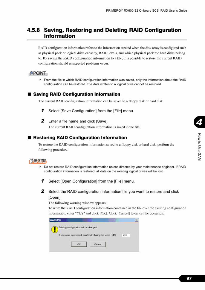
97
PRIMERGY RX600 S2 Onboard SCSI RAID User’s Guide
4
How
to U
se G
AM
4.5.8 Saving, Restoring and Deleting RAID Configuration Information
RAID configuration information refers to the information created when the disk array is configured such
as physical pack or logical drive capacity, RAID levels, and which physical pack the hard disks belong
to. By saving the RAID configuration information to a file, it is possible to restore the current RAID
configuration should unexpected problems occur.
� From the file in which RAID configuration information was saved, only the information about the RAID
configuration can be restored. The data written to a logical drive cannot be restored.
■ Saving RAID Configuration Information
The current RAID configuration information can be saved to a floppy disk or hard disk.
1 Select [Save Configuration] from the [File] menu.
2 Enter a file name and click [Save].
The current RAID configuration information is saved in the file.
■ Restoring RAID Configuration Information
To restore the RAID configuration information saved to a floppy disk or hard disk, perform the
following procedure.
� Do not restore RAID configuration information unless directed by your maintenance engineer. If RAID
configuration information is restored, all data on the existing logical drives will be lost.
1 Select [Open Configuration] from the [File] menu.
2 Select the RAID configuration information file you want to restore and click
[Open].
The following warning window appears.
To write the RAID configuration information contained in the file over the existing configuration
information, enter "YES" and click [OK]. Click [Cancel] to cancel the operation.

98
Chapter 4 How to Use GAM
■ Deleting RAID Configuration Information
The following explains how to delete RAID configuration information.
� Do not delete RAID configuration information unless directed by your maintenance engineer. All data
on the logical drives will be lost by this operation.
1 Select [Clear Configuration] from the [File] menu.
When the following confirmation window appears, click [YES].
If you want to stop deleting the RAID configuration information, click [NO].
When [YES] is clicked, a final confirmation window appears. Enter "YES" and click [OK].
If you want to exit without deleting the existing RAID configuration information, click [Cancel].

99
PRIMERGY RX600 S2 Onboard SCSI RAID User’s Guide
4
How
to U
se G
AM
4.6 Viewing Information
The following information can be viewed using GAM.
• Information of an event or error that occurred
• Array configuration or controller information
• Hard disk information
• Logical drive information
• Request Sense Data information
• Information of a task running in the background
4.6.1 Event
GAM monitors the behaviors of all hard disks and controllers connected to the server. If a behavior that
should be treated as an event (a serious event such as hard disk failure or an event related to spare disk
allocation) is found, that event is noticed to GAM.
Events such as errors, information, or management tasks in the RAID system are displayed in [Log
Information Viewer].
� To write the incidence of an event or error into event logs of the operating system, it is necessary to
install ServerView. Refer to "User's Guide" in the PRIMERGY Documents & Tools CD provided with
the server to install and configure ServerView.
� The GAM Server records detailed information on occurred events in the file "GAMEVLOG.LOG". This
file may be used when investigation is necessary.
The path where "GAMEVLOG.LOG" is stored is as follows, depending on the OS:
• Windows Server 2003 / Windows 2000 Server:
[%SystemRoot%¥System32¥Gamserv¥GAMEVLOG.LOG]
• Windows Server 2003 x64:
[%SystemRoot%¥Syswow64¥Gamserv¥GAMEVLOG.LOG]
• Linux:
[/var/log/gamevlog.log]
� While GAM Client is running, if the IP address of the server to be monitored is changed or the LAN
connection is disconnected, the "Lost connection to server, or server is down" message will be
recorded every 10 minutes.
� If the IP address or computer name of Client is changed after GAM Server was installed, events
cannot be noticed correctly. In this case, it is necessary to uninstall GAM Server first and then install it
again. (If the IP address is automatically obtained from the DHCP server, the IP address may be
changed depending on the timing of powering on/off or restarting the system.)

100
Chapter 4 How to Use GAM
■ Log Information Viewer
[Log Information Viewer] opens automatically when a SCSI array controller is detected at the time of
GAM Client startup.
� Event histories displayed in [Log Information Viewer] are stored in the GAM2CL.LOG file.
When [Log Information Viewer] is opened manually, select [Log Information Viewer] from the [View]
menu. For the meaning of each item displayed in [Log Information Viewer], refer to "4.3.1 Startup
Window Layout/Functions" (�pg.73).
■ Displaying Detailed Information of Each Event
When detailed information of an event displayed in [Log Information Viewer] is needed, display the
[Event ID] window.
Double-click the event displayed in [Log Information Viewer] to display the [Event ID] window.
Detailed information on the selected event is displayed.
Click [OK] to close the [Event ID] window.

101
PRIMERGY RX600 S2 Onboard SCSI RAID User’s Guide
4
How
to U
se G
AM
4.6.2 RAID Controller
The [Controller View] window enables you to view the status of the RAID controller and hard disks or
logical drives connected.
■ Starting Controller View
Double-click the server icon in [Global Status View] to start [Controller View]. If you have not signed
on to the server, the [Sign On] window appears. Sign on to the server using this window.
For details on icons in the [Controller View] window, refer to "4.3.2 [Controller View] Window Layout/
Functions" (�pg.75).

102
Chapter 4 How to Use GAM
■ Displaying RAID Controller Detailed Information
Click [Controller Information] from the [Administration] menu ("[Administration] Menu"�pg.78).
The [Controller Information] window appears. You can set controller options by clicking [Controller
Options].
Click [Close] to close the [Controller Information] window.
� The controller type of an SCSI array controller is displayed in the Model field. For the onboard array
controller, it is displayed as MegaRAID SCSI 320-2E, and for PG-142E3, it is displayed as MegaRAID
SCSI 320-2.
� The Serial Number field is not supported.
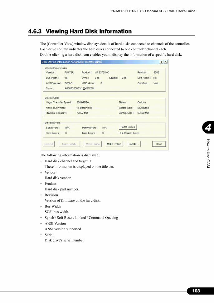
103
PRIMERGY RX600 S2 Onboard SCSI RAID User’s Guide
4
How
to U
se G
AM
4.6.3 Viewing Hard Disk Information
The [Controller View] window displays details of hard disks connected to channels of the controller.
Each drive column indicates the hard disks connected to one controller channel each.
Double-clicking a hard disk icon enables you to display the information of a specific hard disk.
The following information is displayed.
• Hard disk channel and target ID
These information is displayed on the title bar.
• Vendor
Hard disk vendor.
• Product
Hard disk part number.
• Revision
Version of firmware on the hard disk.
• Bus Width
SCSI bus width.
• Synch / Soft Reset / Linked / Command Queuing
• ANSI Version
ANSI version supported.
• Serial
Disk drive's serial number.

104
Chapter 4 How to Use GAM
• Nego. Transfer Speed / Nego. Bus Width
Current transfer speed (MB/second) and current transfer bus width.
� The transfer speed may become slower if an error temporarily occurs in the hard disk. Nor-
mally, if the status of the hard disk is not dead, this phenomenon does not pose any problem to
operation. However, if the performance is very low, the transfer speed is reconfigured by
restarting the system.
• Physical Capacity
Physical capacity of the hard disk.
• Config. size
Hard disk capacity available when connected.
• Sector size
Sector size.
• Status
Current status of the hard disk.
The hard disk status is as follows:
• Hard Errors / Misc Errors / PFA Count
Number of errors.
Errors is as follows:
• Hard Errors : Media errors
• Misc Errors : Errors other than media errors
• PFA Count : Failure expected
� Soft Error / Parity Error display is not supported.
� If PFA Count is Found, refer to "5.2 Preventive Replacement Procedure of a Hard Disk"
(�pg.117) to replace the hard disk.
� In the case of Hard Errors and Misc Errors, because the hard disk is restored using the recov-
ery function, there is no problem in continuing with the operation. If errors occur frequently,
please contact an your maintenance engineer.
The following operations can be performed using buttons.
• Rebuild button
When the hard disk status is "Dead", [Rebuild] is enabled, so that you can specify rebuilding of the
hard disk (�"4.7.2 Rebuild" (pg.112)).
table: The status of the hard disk
Status Meaning
OnLine Online (normal)
Dead Dead (failed)
Dead (absent) Dead (Drive not found)
Rebuilding Rebuild in progress
Unconfigured Unused and available
Hot Spare Spare disk
Critical State of failure being expected (PFA Count)
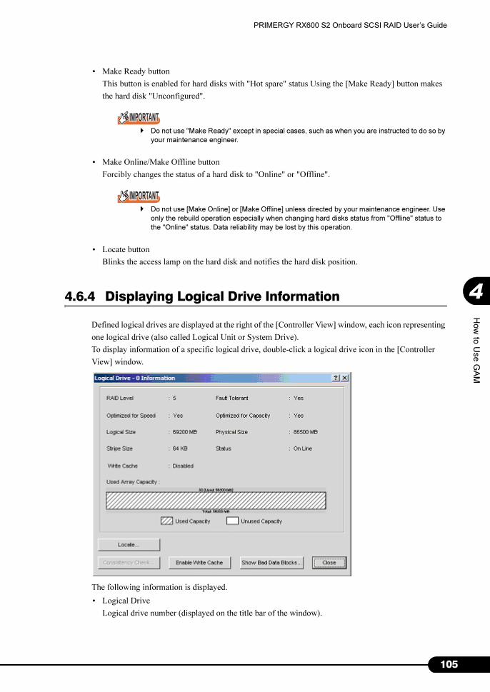
105
PRIMERGY RX600 S2 Onboard SCSI RAID User’s Guide
4
How
to U
se G
AM
• Make Ready button
This button is enabled for hard disks with "Hot spare" status Using the [Make Ready] button makes
the hard disk "Unconfigured".
� Do not use "Make Ready" except in special cases, such as when you are instructed to do so by
your maintenance engineer.
• Make Online/Make Offline button
Forcibly changes the status of a hard disk to "Online" or "Offline".
� Do not use [Make Online] or [Make Offline] unless directed by your maintenance engineer. Use
only the rebuild operation especially when changing hard disks status from "Offline" status to
the "Online" status. Data reliability may be lost by this operation.
• Locate button
Blinks the access lamp on the hard disk and notifies the hard disk position.
4.6.4 Displaying Logical Drive Information
Defined logical drives are displayed at the right of the [Controller View] window, each icon representing
one logical drive (also called Logical Unit or System Drive).
To display information of a specific logical drive, double-click a logical drive icon in the [Controller
View] window.
The following information is displayed.
• Logical Drive
Logical drive number (displayed on the title bar of the window).

106
Chapter 4 How to Use GAM
• RAID Level / Fault Tolerant
RAID level and applicability of redundancy.
• Optimized for Speed / Optimized for Capacity
Whether the speed set, capacity, or redundancy is optimized.
• Logical Size / Physical Size
Logical and physical sizes of the logical drive.
• Stripe Size / Cache Line Size
Stripe size the logical drive uses.
• Write Cache
Write back cache setting.
• Status
Current logical drive's operation status.
The meaning of each status is as follows:
• Used Array Capacity
Of the physical pack capacity, the capacity occupied by the current logical drive.
The following operations can be performed using buttons.
• Locate button
Blinks the access lamps on all the hard disks that compose the logical drive and notifies the hard
disk positions.
• Consistency Check button
If [Consistency Check] is enabled, it is possible manually to perform a consistency check on the
logical drive. For details on consistency check, refer to "4.7.1 Consistency Check" (�pg.111).
• Enable Write Cache / Disable Write Cache
Not supported.
• Show Bad Data Blocks
Not supported.
� On GAM, a RAID 10 logical drive is displayed as RAID 1. For a RAID 10 logical drive, two or more
physical packs are displayed in the Used Array Capacity graph.
table: Logical drive's operation status.
Status Meaning
OnLine Online (normal)
Critical Operating without redundancy
OffLine Offline (failed)

107
PRIMERGY RX600 S2 Onboard SCSI RAID User’s Guide
4
How
to U
se G
AM
4.6.5 Displaying Request Sense Data / NVRAM Error Log
To display hard disk sense information, select [Error Table] from the [View] menu.
The following window appears.
It is possible to save sense information to a file by clicking [Save File].
� Request Sense Data is data used for problem investigation.
� When the system is restarted, Request Sense Data is cleared.
Click the [NVRAM Error Log] tab to display NVRAM logs.
It is possible to save NVRAM logs to a file by clicking [Save File].
� Do not click the [Clear Log] button. Doing so deletes logs.
� NVRAM Error Log is data used for problem investigation.

108
Chapter 4 How to Use GAM
4.6.6 Checking the Progress of a Background Task
Background tasks include processes such as initialization, rebuild, consistency check and capacity
expansion. GAM enables you to check the progress of these tasks in graph form.
■ Foreground/Background Initialize Status
When the initialization of a logical drive is in progress, select [Foreground Initialize Status] or
[Background Initialize Status] from the [View] menu to check its progress.
It is possible to cancel the initialization of the target logical drive with checking the [Cancel] checkbox
of each logical drive and clicking [Cancel].
Click [Close] to close the [Initialize Status] window.
■ Rebuild Status
When a rebuild is in progress, it is possible to check its progress by selecting [Rebuild Status] from the
[View] menu.
Click [Close] to close the [Rebuild Status] window.
� Do not cancel the rebuild.

109
PRIMERGY RX600 S2 Onboard SCSI RAID User’s Guide
4
How
to U
se G
AM
■ Consistency Check Status
When consistency check is in progress, it is possible to check its progress by selecting [Consistency
Check Status] from the [View] menu.
Click [Close] to close the [Consistency Check Status] window.
■ Expand Capacity Status
When capacity expansion is in progress, it is possible to check its progress by selecting [Expand
Capacity Status] from the [View] menu.
Click [Close] to close the [Expand Capacity Status] window.
� Do not restart or shut down the system while a capacity expansion process is in progress. Doing so will
cause data loss.
■ Patrol Read Status
It is possible to check the progress of Patrol Read by selecting [Patrol Read Status] from the [View]
menu.
• Patrol Read Iterations Completed since start up:
Number of times Patrol Read has completed since system startup.
• Patrol Read completed in Current Iteration:
Progress of the on-going Patrol Read.

110
Chapter 4 How to Use GAM
� Click [Start] to force Patrol Read start.
� Click [Stop] to abort the currently running Patrol Read.
� Click [Close] to close the [Patrol Read Status] window.
111
PRIMERGY RX600 S2 Onboard SCSI RAID User’s Guide
4
How
to U
se G
AM
4.7 Maintenance Functions
The following are the functions that can be executed from GAM at the time of
maintenance.
• Logical drive consistency (parity) check (Consistency Check)
• Rebuilding Dead or Offline hard disks (Rebuild)
4.7.1 Consistency Check
Consistency Check is a function to check consistency between data on redundant logical drives and
mirrored data or parity data, in other words, to check reliability of the data.
� Note that consistency checks can be performed on logical drives with redundancy such as Online
RAID 1, RAID 5, and RAID 10 logical drives. Consistency checks cannot be performed on logical
drives without redundancy such as Critical and Offline logical drives.
� In addition to a data integrity check, Consistency Check also automatically corrects media errors of
hard disks (not consistency errors). Normally, media errors are periodically corrected by Patrol Read.
To check consistency, perform the following procedure.
1 Double-click the icon of a logical drive to be performed a consistency check
from the [Controller View] window.
2 Click [Consistency Check] in the [Logical Drive Information] window to start.
• When the consistency check completes successfully, the following log appears in [Log
Information Viewer]:
• If an error is found during the consistency check, the following log is displayed:
I-129 Consistency check is finished.
I-127 Consistency check is finished with errors.
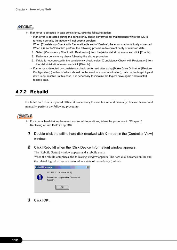
112
Chapter 4 How to Use GAM
� If an error is detected in data consistency, take the following action:
• If an error is detected during the consistency check performed for maintenance while the OS is
running normally, the above will not pose a problem.
When [Consistency Check with Restoration] is set to "Enable", the error is automatically corrected.
When it is set to "Disable", perform the following procedure to correct parity or mirrored data.
1. Select [Consistency Check with Restoration] from the [Administration] menu and click [Enable].
2. Perform a consistency check following the above procedure.
3. If data is not corrected in the consistency check, select [Consistency Check with Restoration] from
the [Administration] menu and click [Disable].
• If an error is detected by consistency check performed after using [Make Drive Online] or [Restore
Configuration] (neither of which should not be used in a normal situation), data on the target logical
drive is not reliable. In this case, it is necessary to initialize the logical drive again and reinstall
reliable data.
4.7.2 Rebuild
If a failed hard disk is replaced offline, it is necessary to execute a rebuild manually. To execute a rebuild
manually, perform the following procedure.
� For normal hard disk replacement and rebuild operations, follow the procedure in "Chapter 5
Replacing a Hard Disk" (�pg.113).
1 Double-click the offline hard disk (marked with X in red) in the [Controller View]
window.
2 Click [Rebuild] when the [Disk Device Information] window appears.
The [Rebuild Status] window appears and a rebuild starts.
When the rebuild completes, the following window appears. The hard disk becomes online and
the related logical drives are restored to a state of redundancy (online).
3 Click [OK].

113
Chapter 5
Replacing a Hard Disk
This chapter explains maintenance related
issues, such as hard disk replacement.
5.1 Replacing a Hard Disk . . . . . . . . . . . . . . . . . . . . . . . . . . . 114
5.2 Preventive Replacement Procedure of a Hard Disk . . . . . 117

114
Chapter 5 Replacing a Hard Disk
5.1 Replacing a Hard Disk
If a hard disk fails, it must be replaced with a new hard disk as soon as possible. The
following explains the procedure for replacing a hard disk. The explanation includes
the method for replacing it during system operation, and that for performing the same
using WebBIOS.
� For replacement, use a hard disk of the same model (with the same capacity and speed) as the disk
that has failed as a rule.
� When connecting a hard disk that was previously used in the disk array configuration to a general
SCSI adapter, perform a low level format on the hard disk connected to the SCSI adapter in advance.
� While the server is turned on, do not remove any hard disks except for when replacing a failed hard
disk. (Only the hard disks in Offline or Unconfigured state can be removed while the server is on.)
5.1.1 Replacing a Hard Disk during System Operation
You can replace a failed hard disk without turning off the system.
1 Check the channel and ID of the failed hard disk using Disk Drive Information of
GAM.
For more details, refer to "4.6.3 Viewing Hard Disk Information" (�pg.103)
If any hard disk is being rebuilt, wait until the process completes. After its completion, check the
failed hard disk using Disk Drive Information.
2 Locate the failed hard disk using its ID and channel checked by GAM.
Also, make sure that the Hard disk failure LED corresponding to the failed hard disk is lit.
3 Pull out the plastic lever 90 degrees towards you, and also pull out the failed
hard disk unit 1 to 3cm to disconnect it from the SCSI bus.
Do not pull out the hard disk unit completely from the server at this point.
4 Wait 1 minute or more.
Please wait until the rotation of the motor in the hard disk unit stops.
5 Pull out the failed hard disk from the hard disk bay.
6 Install a new hard disk in the hard disk bay where the failed hard disk was
previously installed.
115
PRIMERGY RX600 S2 Onboard SCSI RAID User’s Guide
5
Repla
cin
g a
Hard
Dis
k
7 Check the following.
The confirmation procedure differs depending on whether any spare disk had been set before the
hard disk failure.
If any spare disk had been set
A short while after installing a new hard disk, it automatically becomes a spare disk, and the Hard
disk failure LED corresponding to the hard disk turns off.
Make sure that the status of the replaced hard disk has changed to "Hot Spare" from "Dead" using
Disk Device Information of GAM.
If no spare disk had been set
A short while after installing a new hard disk, rebuilding is started automatically on the installed
hard disk. When rebuilding is started, the Hard disk failure LED corresponding to the hard disk
that was lit starts to blink, and turns off after rebuilding is completed.
After its completion, make sure that the status of the replaced hard disk has changed to "OnLine"
from "Dead" using Disk Device Information of GAM.
� If restart or shutdown is executed during the rebuild, rebuild resumes at the next launch starting from
the position where the process stopped.
5.1.2 Replacing a Hard Disk Using WebBIOS
1 Check the channel and ID of the failed hard disk using [Physical Devices] of
WebBIOS.
For more details, refer to "2.11.2 Viewing the Hard Disk Status" (�pg.49).
2 Locate the failed hard disk using its ID and channel checked by WebBIOS.
3 Make sure that the Hard disk failure LED corresponding to the failed hard disk
is lit.
4 Pull out the plastic lever 90 degrees towards you, and also pull out the failed
hard disk unit 1 to 3cm to disconnect it from the SCSI bus.
Do not pull out the hard disk unit completely from the server at this point.
5 Wait 1 minute or more.
Please wait until the rotation of the motor in the hard disk unit stops.
6 Pull out the failed hard disk from the hard disk bay.
7 Install a new hard disk in the hard disk bay where the failed hard disk was
previously installed.
116
Chapter 5 Replacing a Hard Disk
8 Check the following.
The confirmation procedure differs depending on whether any spare disk had been set before the
hard disk failure.
If any spare disk had been set
A short while after installing a new hard disk, it automatically becomes a spare disk, and the Hard
disk failure LED corresponding to the hard disk turns off.
Make sure that the status of the replaced hard disk has changed to "Hot Spare" from "Dead" using
Disk Device Information of WebBIOS.
If no spare disk had been set
A short while after installing a new hard disk, rebuilding is started automatically on the installed
hard disk. When rebuilding is started, the Hard disk failure LED corresponding to the hard disk
that was lit starts to blink, and turns off after rebuilding is completed.
After its completion, make sure that the status of the replaced hard disk has changed to "OnLine"
from "Dead" using Disk Device Information of WebBIOS.

117
PRIMERGY RX600 S2 Onboard SCSI RAID User’s Guide
5
Repla
cin
g a
Hard
Dis
k
5.2 Preventive Replacement Procedure of a Hard Disk
When the failure prediction function of the hard disk (PFA Count) reports the Critical
status of a hard disk, it may fail at a future date. If the Critical status is reported,
perform preventive replacement of the hard disk.
� For preventive replacement, use a hard disk of the same model (with the same capacity and speed) as
the likely-to-fail disk as a rule.
5.2.1 Checking Applicability of Redundancy
Perform the following procedure to check whether the array system including the hard disk targeted for
preventive replacement is redundant.
1 Right-click and select the logical drive icon displayed in the [Logical Drives]
field in the [Controller View] window of GAM.
The icons of the hard disks composing the logical drive appear in white.
� Right-clicking the logical drive icon again returns the display to its original status.
2 Check all the hard disks included in each logical drive.
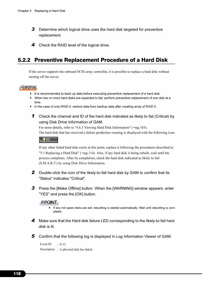
118
Chapter 5 Replacing a Hard Disk
3 Determine which logical drive uses the hard disk targeted for preventive
replacement.
4 Check the RAID level of the logical drive.
5.2.2 Preventive Replacement Procedure of a Hard Disk
If the server supports the onboard SCSI array controller, it is possible to replace a hard disk without
turning off the server.
� It is recommended to back up data before executing preventive replacement of a hard disk.
� When two or more hard disks are expected to fail, perform preventive replacement of one disk at a
time.
� In the case of only RAID 0, restore data from backup data after creating array of RAID 0.
1 Check the channel and ID of the hard disk indicated as likely to fail (Critical) by
using Disk Drive Information of GAM.
For more details, refer to "4.6.3 Viewing Hard Disk Information" (�pg.103).
The hard disk that has received a failure prediction warning is displayed with the following icon.
If any other failed hard disk exists at this point, replace it following the procedures described in
"5.1 Replacing a Hard Disk" (�pg.114). Also, if any hard disk is being rebuilt, wait until the
process completes. After its completion, check the hard disk indicated as likely to fail
(S.M.A.R.T.) by using Disk Drive Information.
2 Double-click the icon of the likely-to-fail hard disk by GAM to confirm that its
"Status" indicates "Critical".
3 Press the [Make Offline] button. When the [WARNING] window appears, enter
"YES" and press the [OK] button.
� If any hot spare disks are set, rebuilding is started automatically. Wait until rebuilding is com-
pleted.
4 Make sure that the Hard disk failure LED corresponding to the likely-to-fail hard
disk is lit.
5 Confirm that the following log is displayed in Log Information Viewer of GAM.
Event ID :S-12
Description :A physical disk has failed.
119
PRIMERGY RX600 S2 Onboard SCSI RAID User’s Guide
5
Repla
cin
g a
Hard
Dis
k
6 Pull out the plastic lever 90 degrees towards you, and also pull out the likely-to-
fail hard disk unit 1 to 3cm to disconnect it from the SCSI bus.
� Do not pull out the hard disk unit completely from the server at this point.
7 Wait 1 minute or more.
Please wait until the rotation of the motor in the hard disk unit stops.
8 Pull out the likely-to-fail hard disk from the hard disk bay.
9 Install a new hard disk in the hard disk bay where the likely-to-fail hard disk was
previously installed.
10 Check the following.
The confirmation procedure differs depending on whether any spare disk had been set before the
hard disk failure.
If any spare disk had been set
A short while after installing a new hard disk, it automatically becomes a spare disk, and the Hard
disk failure LED corresponding to the hard disk turns off.
Make sure that the status of the replaced hard disk has changed to "Hot Spare" using Disk Device
Information of GAM.
If no spare disk had been set
A short while after installing a new hard disk, rebuilding is started automatically on the installed
hard disk. When rebuilding is started, the Hard disk failure LED corresponding to the hard disk
that was lit starts to blink, and turns off after rebuilding is completed.
After its completion, make sure that the status of the replaced hard disk has changed to "OnLine"
using Disk Device Information of GAM.

120
Chapter 5 Replacing a Hard Disk

121
Appendix
This chapter explains RAID level and list of GAM
error codes.
A RAID Level . . . . . . . . . . . . . . . . . . . . . . . . . . . . . . . . . . . 122
B List of GAM Error Codes . . . . . . . . . . . . . . . . . . . . . . . . . 125
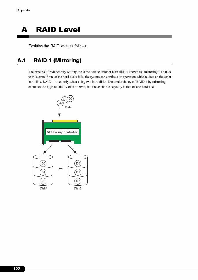
122
Appendix
A RAID Level
Explains the RAID level as follows.
A.1 RAID 1 (Mirroring)
The process of redundantly writing the same data to another hard disk is known as "mirroring". Thanks
to this, even if one of the hard disks fails, the system can continue its operation with the data on the other
hard disk. RAID 1 is set only when using two hard disks. Data redundancy of RAID 1 by mirroring
enhances the high reliability of the server, but the available capacity is that of one hard disk.
D1
D0D0 D0
D1
D2 D2
=
D2D1D0
Data
Disk1 Disk2
ka

123
PRIMERGY RX600 S2 Onboard SCSI RAID User’s Guide
Appendix
A
A.2 RAID 5 (Striping + Parity)
In addition to striping (the process distributing data across multiple hard disks), RAID 5 creates parity
data for redundancy. Parity data is derived via an algorithm from the original data. For example, when
writing six blocks of data (D0 - D5) with three hard disks, each data block and the calculated parity data
P (DX, DY) are distributed across the hard disks (see below figure). Because redundancy is achieved by
the parity data, a hard disk worth of capacity is used for the parity data.
D3
D0 D1
D2
D4 D5
P(D0,D1)
P(D2,D3)
P(D4,D5)
D5D4D3D2D1D0
Data
Disk1 Disk3Disk2

124
Appendix
A.3 RAID 10 (Mirroring + Striping)
In addition to striping (the process distributing data across multiple hard disks), RAID 10 mirrors the
data for redundancy. For example, when writing six blocks of data (D0 - D5) with three hard disks, each
data block and redundant data are distributed across the hard disks (see below figure). Reliability is
enhanced by writing the data across three hard disks, and redundancy is achieved with the redundant
data. Although only half of the capacity of all hard disks is available, it is better performance than RAID
5.
D3
D0 D1
D2
D4 D5
D0
D2
D4 D5
D1
D3
RAID1 RAID1
RAID0
D5D4D3D2D1D0
Data
Disk1 Disk3Disk2 Disk4
125
PRIMERGY RX600 S2 Onboard SCSI RAID User’s Guide
Appendix
A
B List of GAM Error Codes
By installing ServerView, errors that occur can be logged to Event Viewer. The
following is a list of logs written to the application log of Windows Event Viewer as
events of the "Fujitsu ServerView Service" source. The device address is logged at
the beginning of the event log (part within [ ]). The device address indicates where
the event occurred.
� Unless ServerView is installed, event logging to Event Viewer will not occur. Refer to "User's Guide" in
the PRIMERGY Documents & Tools CD provided with the server to install and configure ServerView.
The number within the brackets of the GAM ID is displayed in hexadecimal.
table: Meaning of event log's character strings
character strings Meaning
clt: Controller ID
chn: Channel
tgt: Target ID of the physical device
logdrv: Logical drive number
table: List of event log
GAM ID Severity Description Details Corrective action
1
(0x01)Info/1 A physical disk has
been placed online.A hard disk is now in
Online state. The following
are possible causes:
• Rebuilding completed.
• It was embedded into the
configuration.
• Make Online was
executed.
None.
2
(0x02)Info/1 Physical disk
added as hot spare.A hard disk was set as a hot
spare.
None.
3
(0x03)Warning/2 Physical disk error
found.
• A bad sector was found
on the media.
• A mechanical failure of
the device. The host
device detected an
invalid sequence.
Because the controller is
implementing a recovery, no
action is required as long as the
corresponding disk is Online.
However, if this occurs
frequently, it is recommended to
replace the disk as a
precautionary measure.
4
(0x04)Warning/2 Physical disk PFA
condition found;
this disk may fail
soon.
A failure was predicted for
the hard disk.
Refer to "5.2 Preventive
Replacement Procedure of a Hard
Disk" (�pg.117).

126
Appendix
5
(0x05)Info/1 An automatic
rebuild has started.Rebuild started. If there is a dead hot spare hard
disk, replace it with a new hard
disk.
6
(0x06)Info/1 A rebuild has
started.Rebuild started via a
command.
None.
7
(0x07)Info/1 Rebuild is over. Rebuild completed
successfully.
None.
8
(0x08)Warning/2 Rebuild is
cancelled.Rebuild was canceled. Re-execute the rebuild.
9
(0x09)Error/3 Rebuild stopped
with error.Rebuild terminated
abnormally.
Check the logs surrounding the
process and perform necessary
actions.
10
(0x0a)Error/3 Rebuild stopped
with error. New
device failed.
Rebuild terminated
abnormally due to a bad
hard disk for the rebuild.
Replace the hard disk again and
re-execute the rebuild process.
11
(0x0b)Error/3 Rebuild stopped
because logical
drive failed.
The source disk of the
rebuild failed.
Contact an office listed in the
"Contact Information" of "Start
Guide".
12
(0x0c)Error/3 Physical disk has
failed.A hard disk failed. Replace the Dead hard disk and
rebuild.
13
(0x0d)Info/1 A new physical
disk has been
found.
A new hard disk was
detected. This is logged in
the following situations:
• A hard disk was added.
• The controller was
powered on.
• A controller was added.
• The system was
rebooted.
None.
14
(0x0e)Info/1 A physical disk has
been removed.A hard disk was removed. None.
15
(0x0f)Info/1 A previously
configured disk is
now available.
A hard disk is now in
Unconfigured state.
None.
16
(0x10)Info/1 Expand Capacity
Started.The capacity expansion
process started.
None.
17
(0x11)Info/1 Expand Capacity
Completed.The capacity expansion
process completed.
None.
18
(0x12)Error/3 Expand Capacity
Stopped with error.Multiple hard disks failed
and the capacity expansion
process terminated
abnormally.
Recreate the array configuration
and restore the data from backup.
19
(0x13)Warning/2 SCSI command
timeout on hard
device.
A command timeout was
detected.
Because the firmware is
implementing a recovery, there is
no problem as long as there are
no Dead hard disks.
table: List of event log
GAM ID Severity Description Details Corrective action

127
PRIMERGY RX600 S2 Onboard SCSI RAID User’s Guide
Appendix
A
20
(0x14)Error/3 SCSI command
abort on hard disk.
• The user aborted the
command.
• The firmware aborted the
command to recover
from an error.
• A device aborted the
command.
Because the firmware is
implementing a recovery, there is
no problem as long as there are
no Dead hard disks.
21
(0x15)Warning/2 SCSI command
retried on hard
disk.
• The command timed out.
• A bus reset occurred.
• A device reset occurred.
Because the firmware is
implementing a recovery, there is
no problem as long as there are
no Dead hard disks.
22
(0x16)Warning/2 Parity error found. A parity error was detected. If the error occurs frequently,
replace the SCSI cable or SCSI
BP.
23
(0x17)Warning/2 Soft error found. An error was detected in a
hard disk, but it was
resolved.
No action is required.
If this frequently occurs, replace
the hard disk as a precautionary
measure.
24
(0x18)Warning/2 Misc error found. • A hard disk reported an
error.
• The Read/Write
command timed out.
• A hard disk is busy.
No action is required.
If this frequently occurs, replace
the hard disk as a precautionary
measure.
25
(0x19)Info/1 SCSI device reset. The firmware issued a reset
for recovery.
No action is required.
If this message occurs frequently,
check the logs surrounding the
process and perform necessary
actions.
28
(0x1c)Error/3 Request Sense
Data available.A hard disk reported sense
information.
Because the controller is
implementing a recovery, no
action is required as long as the
corresponding disk is Online.
29
(0x1d)Info/1 Initialization
started.The hard disk format
started.
Wait until the format is
completed.
30
(0x1e)Info/1 Initialization
completed.The hard disk format
completed.
None.
31
(0x1f)Warning/2 Initialization
failed.The hard disk format failed. Replace the hard disk.
32
(0x20)Error/3 Initialization
canceled.The hard disk format was
canceled.
Format the disk again.
33 ~ 41
(0x21)
~
(0x29)
Error/3 A physical disk
failed because...A hard disk failed. Replace the hard disk and
perform the rebuild process.
42
(0x2a)Error/3 A physical disk set
to failed state by
host.
Make Offline was executed. Replace the hard disk and
perform the rebuild process.
43 ~ 49
(0x2b)
~
(0x31)
Error/3 A physical disk
failed because...A hard disk failed. Replace the hard disk and
perform the rebuild process.
table: List of event log
GAM ID Severity Description Details Corrective action
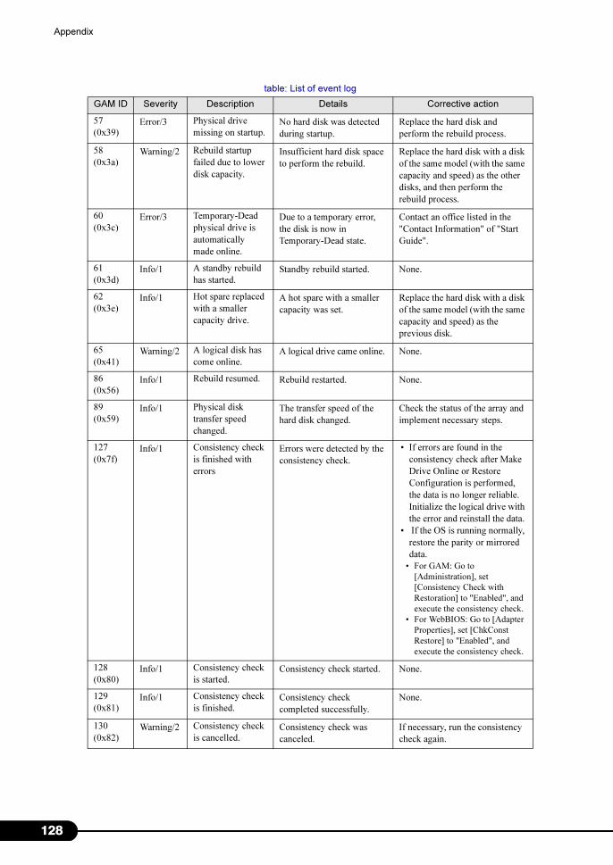
128
Appendix
57
(0x39)Error/3 Physical drive
missing on startup.No hard disk was detected
during startup.
Replace the hard disk and
perform the rebuild process.
58
(0x3a)Warning/2 Rebuild startup
failed due to lower
disk capacity.
Insufficient hard disk space
to perform the rebuild.
Replace the hard disk with a disk
of the same model (with the same
capacity and speed) as the other
disks, and then perform the
rebuild process.
60
(0x3c)Error/3 Temporary-Dead
physical drive is
automatically
made online.
Due to a temporary error,
the disk is now in
Temporary-Dead state.
Contact an office listed in the
"Contact Information" of "Start
Guide".
61
(0x3d)Info/1 A standby rebuild
has started.Standby rebuild started. None.
62
(0x3e)Info/1 Hot spare replaced
with a smaller
capacity drive.
A hot spare with a smaller
capacity was set.
Replace the hard disk with a disk
of the same model (with the same
capacity and speed) as the
previous disk.
65
(0x41)Warning/2 A logical disk has
come online.A logical drive came online. None.
86
(0x56)Info/1 Rebuild resumed. Rebuild restarted. None.
89
(0x59)Info/1 Physical disk
transfer speed
changed.
The transfer speed of the
hard disk changed.
Check the status of the array and
implement necessary steps.
127
(0x7f)Info/1 Consistency check
is finished with
errors
Errors were detected by the
consistency check.
• If errors are found in the
consistency check after Make
Drive Online or Restore
Configuration is performed,
the data is no longer reliable.
Initialize the logical drive with
the error and reinstall the data.
• If the OS is running normally,
restore the parity or mirrored
data.
• For GAM: Go to
[Administration], set
[Consistency Check with
Restoration] to "Enabled", and
execute the consistency check.
• For WebBIOS: Go to [Adapter
Properties], set [ChkConst
Restore] to "Enabled", and
execute the consistency check.
128
(0x80)Info/1 Consistency check
is started.Consistency check started. None.
129
(0x81)Info/1 Consistency check
is finished.Consistency check
completed successfully.
None.
130
(0x82)Warning/2 Consistency check
is cancelled.Consistency check was
canceled.
If necessary, run the consistency
check again.
table: List of event log
GAM ID Severity Description Details Corrective action
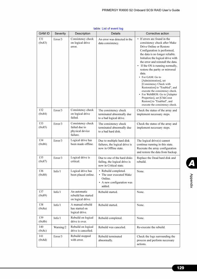
129
PRIMERGY RX600 S2 Onboard SCSI RAID User’s Guide
Appendix
A
131
(0x83)Error/3 Consistency check
on logical drive
error.
An error was detected in the
data consistency.
• If errors are found in the
consistency check after Make
Drive Online or Restore
Configuration is performed,
the data is no longer reliable.
Initialize the logical drive with
the error and reinstall the data.
• If the OS is running normally,
restore the parity or mirrored
data.
• For GAM: Go to
[Administration], set
[Consistency Check with
Restoration] to "Enabled", and
execute the consistency check.
• For WebBIOS: Go to [Adapter
Properties], set [ChkConst
Restore] to "Enabled", and
execute the consistency check.
132
(0x84)Error/3 Consistency check
on logical drive
failed.
The consistency check
terminated abnormally due
to a bad logical drive.
Check the status of the array and
implement necessary steps.
133
(0x85)Error/3 Consistency check
failed due to
physical device
failure.
The consistency check
terminated abnormally due
to a bad hard disk.
Check the status of the array and
implement necessary steps.
134
(0x86)Error/3 Logical drive has
been made offline.Due to multiple hard disk
failures, the logical drive is
now in Offline state.
The logical drive(s) cannot
continue running in this state.
Recreate the array configuration
and restore the data from backup.
135
(0x87)Error/3 Logical drive is
critical.Due to one of the hard disks
failing, the logical drive is
now in Critical state.
Replace the Dead hard disk and
rebuild.
136
(0x88)Info/1 Logical drive has
been placed online.
• Rebuild completed.
• The user executed Make
Online.
• A new configuration was
added.
None.
137
(0x89)Info/1 An automatic
rebuild has started
on logical drive.
Rebuild started. None.
138
(0x8a)Info/1 A manual rebuild
has started on
logical drive.
Rebuild started. None.
139
(0x8b)Info/1 Rebuild on logical
drive is over.Rebuild completed. None.
140
(0x8c)Warning/2 Rebuild on logical
drive is cancelled.Rebuild was canceled. Re-execute the rebuild.
141
(0x8d)Error/3 Rebuild stopped
with error.Rebuild terminated
abnormally.
Check the logs surrounding the
process and perform necessary
actions.
table: List of event log
GAM ID Severity Description Details Corrective action

130
Appendix
142
(0x8e)Error/3 Rebuild stopped
with error. New
device failed.
Rebuild terminated
abnormally due to a bad
hard disk for the rebuild.
Replace the hard disk again and
re-execute the rebuild process.
143
(0x8f)Error/3 Rebuild stopped
because logical
drive failed.
The source disk of the
rebuild failed.
Contact an office listed in the
"Contact Information" of "Start
Guide".
144
(0x90)Info/1 Logical drive
initialization
started.
The initialization of a
logical drive started.
None.
145
(0x91)Info/1 Logical drive
initialization done.The initialization of the
logical drive completed.
None.
146
(0x92)Warning/2 Logical drive
initialization
cancelled.
The initialization of the
logical drive was canceled.
Re-execute the initialization
process.
147
(0x93)Error/3 Logical drive
initialization failed.The initialization terminated
abnormally.
Replace the hard disk and
perform the rebuild process.
148
(0x94)Info/1 A logical drive has
been found.
• A new configuration was
added.
• The capacity expansion
process completed.
• A new controller was
added.
• The system was
rebooted.
None.
149
(0x95)Info/1 A logical drive has
been deleted.A logical drive was deleted. None.
150
(0x96)Info/1 Expand Capacity
Started.The capacity expansion
process started.
None.
151
(0x97)Info/1 Expand Capacity
Completed.The capacity expansion
process completed.
None.
152
(0x98)Error/3 Expand Capacity
stopped with error.The capacity expansion
process terminated
abnormally due to multiple
hard disks failed.
The logical drive(s) cannot
continue running in this state.
Recreate the array configuration
and restore the data from backup.
153
(0x99)Error/3 Bad Blocks found. A bad block was detected
during the consistency
check, rebuild, or capacity
expansion process.
• During consistency check/
capacity expansion process:
The bad block will be repaired,
so there is no problem.
• During rebuild: If a corrupted
file is found, restore it from the
backup.
154
(0x9a)Info/1 System drive size
changed.
• The capacity of the
logical drive changed.
• Additional capacity was
added by the capacity
expansion process.
None.
155
(0x9b)Info/1 System drive type
changed.A new configuration was
added with the completion
of the capacity expansion
process.
None.
table: List of event log
GAM ID Severity Description Details Corrective action
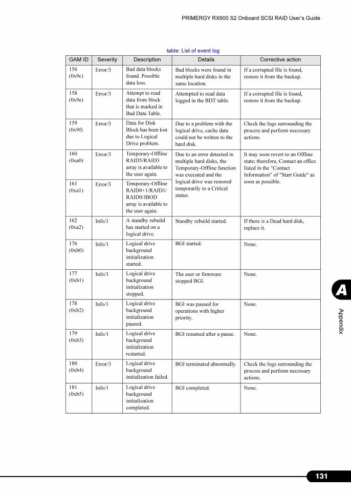
131
PRIMERGY RX600 S2 Onboard SCSI RAID User’s Guide
Appendix
A
156
(0x9c)Error/3 Bad data blocks
found. Possible
data loss.
Bad blocks were found in
multiple hard disks in the
same location.
If a corrupted file is found,
restore it from the backup.
158
(0x9e)Error/3 Attempt to read
data from block
that is marked in
Bad Data Table.
Attempted to read data
logged in the BDT table.
If a corrupted file is found,
restore it from the backup.
159
(0x9f)Error/3 Data for Disk
Block has been lost
due to Logical
Drive problem.
Due to a problem with the
logical drive, cache data
could not be written to the
hard disk.
Check the logs surrounding the
process and perform necessary
actions.
160
(0xa0)Error/3 Temporary-Offline
RAID5/RAID3
array is available to
the user again.
Due to an error detected in
multiple hard disks, the
Temporary-Offline function
was executed and the
logical drive was restored
temporarily to a Critical
status.
It may soon revert to an Offline
state; therefore, Contact an office
listed in the "Contact
Information" of "Start Guide" as
soon as possible. 161
(0xa1)Error/3 Temporary-Offline
RAID0+1/RAID1/
RAID0/JBOD
array is available to
the user again.
162
(0xa2)Info/1 A standby rebuild
has started on a
logical drive.
Standby rebuild started. If there is a Dead hard disk,
replace it.
176
(0xb0)Info/1 Logical drive
background
initialization
started.
BGI started. None.
177
(0xb1)Info/1 Logical drive
background
initialization
stopped.
The user or firmware
stopped BGI.
None.
178
(0xb2)Info/1 Logical drive
background
initialization
paused.
BGI was paused for
operations with higher
priority.
None.
179
(0xb3)Info/1 Logical drive
background
initialization
restarted.
BGI resumed after a pause. None.
180
(0xb4)Error/3 Logical drive
background
initialization failed.
BGI terminated abnormally. Check the logs surrounding the
process and perform necessary
actions.
181
(0xb5)Info/1 Logical drive
background
initialization
completed.
BGI completed. None.
table: List of event log
GAM ID Severity Description Details Corrective action
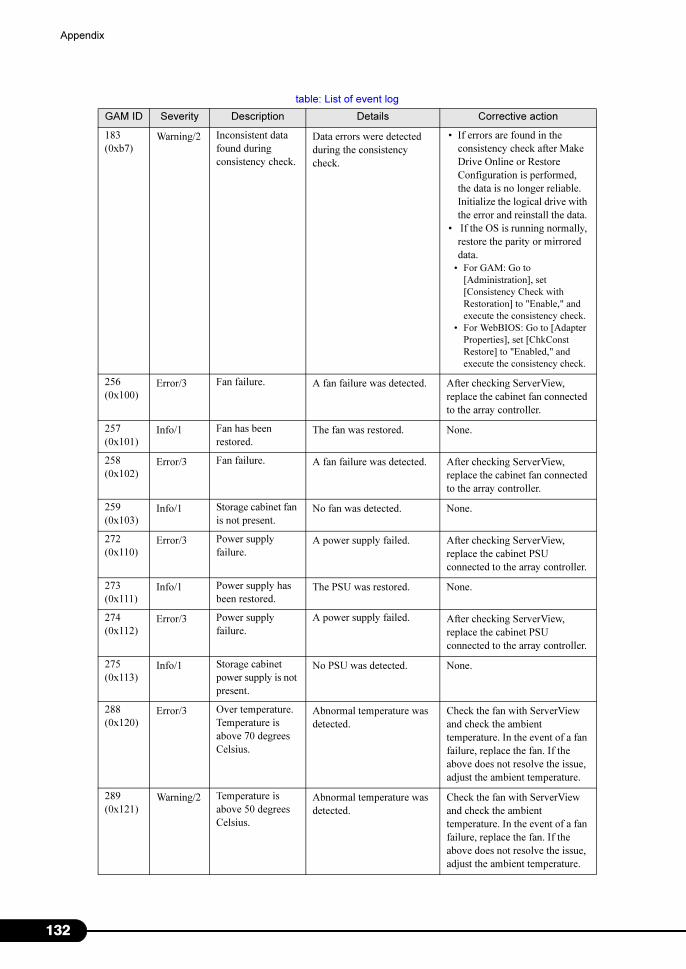
132
Appendix
183
(0xb7)Warning/2 Inconsistent data
found during
consistency check.
Data errors were detected
during the consistency
check.
• If errors are found in the
consistency check after Make
Drive Online or Restore
Configuration is performed,
the data is no longer reliable.
Initialize the logical drive with
the error and reinstall the data.
• If the OS is running normally,
restore the parity or mirrored
data.
• For GAM: Go to
[Administration], set
[Consistency Check with
Restoration] to "Enable," and
execute the consistency check.
• For WebBIOS: Go to [Adapter
Properties], set [ChkConst
Restore] to "Enabled," and
execute the consistency check.
256
(0x100)Error/3 Fan failure. A fan failure was detected. After checking ServerView,
replace the cabinet fan connected
to the array controller.
257
(0x101)Info/1 Fan has been
restored.The fan was restored. None.
258
(0x102)Error/3 Fan failure. A fan failure was detected. After checking ServerView,
replace the cabinet fan connected
to the array controller.
259
(0x103)Info/1 Storage cabinet fan
is not present.No fan was detected. None.
272
(0x110)Error/3 Power supply
failure.A power supply failed. After checking ServerView,
replace the cabinet PSU
connected to the array controller.
273
(0x111)Info/1 Power supply has
been restored.The PSU was restored. None.
274
(0x112)Error/3 Power supply
failure.
A power supply failed. After checking ServerView,
replace the cabinet PSU
connected to the array controller.
275
(0x113)Info/1 Storage cabinet
power supply is not
present.
No PSU was detected. None.
288
(0x120)Error/3 Over temperature.
Temperature is
above 70 degrees
Celsius.
Abnormal temperature was
detected.
Check the fan with ServerView
and check the ambient
temperature. In the event of a fan
failure, replace the fan. If the
above does not resolve the issue,
adjust the ambient temperature.
289
(0x121)Warning/2 Temperature is
above 50 degrees
Celsius.
Abnormal temperature was
detected.
Check the fan with ServerView
and check the ambient
temperature. In the event of a fan
failure, replace the fan. If the
above does not resolve the issue,
adjust the ambient temperature.
table: List of event log
GAM ID Severity Description Details Corrective action

133
PRIMERGY RX600 S2 Onboard SCSI RAID User’s Guide
Appendix
A
290
(0x122)Info/1 Normal
temperature has
been restored.
The temperature is now
normal.
None.
291
(0x123)Error/3 Over temperature. Abnormal temperature was
detected.
Check the fan with ServerView
and check the ambient
temperature. In the event of a fan
failure, replace the fan. If the
above does not resolve the issue,
adjust the ambient temperature.
292
(0x124)Info/1 Storage cabinet
temperature sensor
is not present.
No temperature sensor was
detected.
None.
306
(0x132)Info/1 Storage Works
enclosure reported
normal state.
The cabinet was restored to
a normal state.
None.
320
(0x140)Error/3 Fan failure. A fan failure was detected. After checking ServerView,
replace the cabinet fan connected
to the array controller.
321
(0x141)Info/1 Fan has been
restored.The fan was restored. None.
322
(0x142)Info/1 Fan is not present. No fan was detected. None.
323
(0x143)Error/3 Power supply
failure.A power supply failed. After checking ServerView,
replace the cabinet PSU
connected to the array controller.
324
(0x144)Info/1 Power supply has
been restored.The PSU was restored. None.
325
(0x145)Info/1 Power supply is
not present.No PSU was detected. None.
326
(0x146)Error/3 Temperature is
over safe limit.
Failure imminent.
Abnormal temperature was
detected.
Check the fan with ServerView
and check the ambient
temperature. In the event of a fan
failure, replace the fan. If the
above does not resolve the issue,
adjust the ambient temperature.
327
(0x147)Warning/2 Temperature is
above working
limit.
Abnormal temperature was
detected.
Check the fan with ServerView
and check the ambient
temperature. In the event of a fan
failure, replace the fan. If the
above does not resolve the issue,
adjust the ambient temperature.
328
(0x148)Info/1 Normal
temperature has
been restored.
The temperature is now
normal.
None.
329
(0x149)Info/1 Temperature
sensor is not
present.
No temperature sensor was
detected.
None.
330
(0x14a)Warning/2 Enclosure access
critical.An error occurred in the
access to the enclosure.
Replace the SCSI BP or SCSI
cable.
table: List of event log
GAM ID Severity Description Details Corrective action

134
Appendix
331
(0x14b)Info/1 Enclosure access
has been restored.Enclosure access was
restored.
None.
332
(0x14c)Error/3 Enclosure access is
offline.Could not access the
enclosure.
Replace the SCSI BP or SCSI
cable.
384
(0x180)Info/1 Array management
server software
started
successfully.
GAM Server started
successfully.
None.
385
(0x181)Error/3 Write back error Failed to write cache. Check the logs surrounding the
process and perform necessary
actions.
386
(0x182)Warning/2 Internal log
structures getting
full, PLEASE
SHUTDOWN
AND RESET THE
SYSTEM IN THE
NEAR FUTURE.
Due to many configuration
changes, the configuration
change table is full.
After successfully shutting down,
turn off and then turn on the
server.
If the same log is not deleted,
replace the controller.
388
(0x184)Error/3 Controller is dead.
System is
disconnecting from
this controller.
The controller failed. Replace the array controller.
389
(0x185)Warning/2 Controller has been
reset.The controller received a
reset command.
Because the firmware is
implementing a recovery, there is
no problem as long as there are
no Dead hard disks.
390
(0x186)Info/1 Controller is
found.
• A new controller was
detected.
• GAM Server restarted.
• The system was
rebooted.
None.
391
(0x187)Error/3 Controller is gone.
System is
disconnecting from
this controller.
• Power supplied to the
controller was cut off.
• The controller was
removed from the
system.
Check to see whether the array
controller is correctly installed to
the server.
If the above does not resolve the
issue, replace the following:
• Array controller
• Motherboard
392
(0x188)Info/1 BBU Present. A battery module was
detected.
None.
393
(0x189)Warning/2 BBU Power Low. The battery charge level is
under the warning
threshold.
No action is required if this
occurred during installation or
prolonged power off.
In other cases, replace the battery.
394
(0x18a)Info/1 BBU Power OK. The battery is fully charged.
(The charge level is above
the set threshold.)
None.
table: List of event log
GAM ID Severity Description Details Corrective action
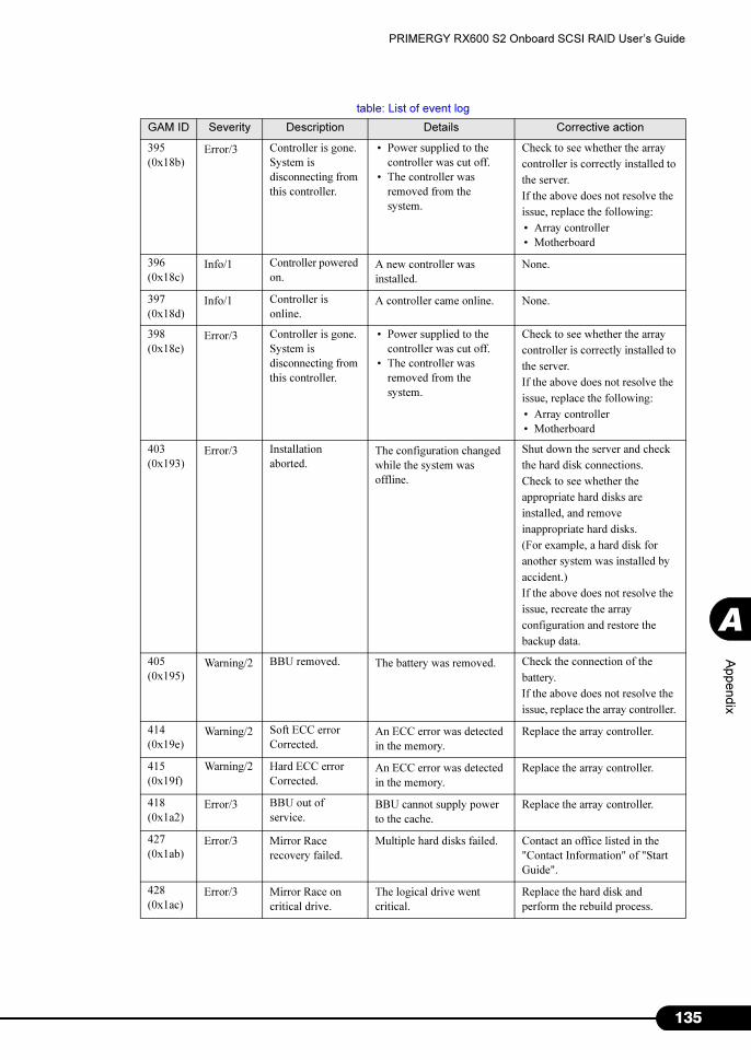
135
PRIMERGY RX600 S2 Onboard SCSI RAID User’s Guide
Appendix
A
395
(0x18b)Error/3 Controller is gone.
System is
disconnecting from
this controller.
• Power supplied to the
controller was cut off.
• The controller was
removed from the
system.
Check to see whether the array
controller is correctly installed to
the server.
If the above does not resolve the
issue, replace the following:
• Array controller
• Motherboard
396
(0x18c)Info/1 Controller powered
on.A new controller was
installed.
None.
397
(0x18d)Info/1 Controller is
online.A controller came online. None.
398
(0x18e)Error/3 Controller is gone.
System is
disconnecting from
this controller.
• Power supplied to the
controller was cut off.
• The controller was
removed from the
system.
Check to see whether the array
controller is correctly installed to
the server.
If the above does not resolve the
issue, replace the following:
• Array controller
• Motherboard
403
(0x193)Error/3 Installation
aborted.The configuration changed
while the system was
offline.
Shut down the server and check
the hard disk connections.
Check to see whether the
appropriate hard disks are
installed, and remove
inappropriate hard disks.
(For example, a hard disk for
another system was installed by
accident.)
If the above does not resolve the
issue, recreate the array
configuration and restore the
backup data.
405
(0x195)Warning/2 BBU removed. The battery was removed. Check the connection of the
battery.
If the above does not resolve the
issue, replace the array controller.
414
(0x19e)Warning/2 Soft ECC error
Corrected.An ECC error was detected
in the memory.
Replace the array controller.
415
(0x19f)
Warning/2 Hard ECC error
Corrected.An ECC error was detected
in the memory.
Replace the array controller.
418
(0x1a2)Error/3 BBU out of
service.BBU cannot supply power
to the cache.
Replace the array controller.
427
(0x1ab)Error/3 Mirror Race
recovery failed.
Multiple hard disks failed. Contact an office listed in the
"Contact Information" of "Start
Guide".
428
(0x1ac)Error/3 Mirror Race on
critical drive.
The logical drive went
critical.
Replace the hard disk and
perform the rebuild process.
table: List of event log
GAM ID Severity Description Details Corrective action

136
Appendix
431
(0x1af)Error/3 Controller
improperly
shutdown! Data
may have been
lost.
The consistency of the
logical drive was lost due to
an invalid shutdown
process.
Restore the parity or mirrored
data.
• For GAM: Go to the
[Administration] menu, set
[Consistency Check with
Restoration] to "Enabled", and
execute the consistency check.
After the process is completed,
"Disabled" the above setting.
• For WebBIOS: Go to [Adapter
Properties], set [ChkConst
Restore] to "Enabled", and
execute the consistency check.
After the process is completed,
"Disabled" the above setting.
442
(0x1ba)Info/1 Patrol Read
iteration
completed.
Patrol Read completed. None.
512
(0x200)Info/1 System started.- The server or GAM Server
started.
None.
514
(0x202)Info/1 User logged in.- The user logged in to the
server.
None.
515
(0x203)Info/1 User logged out.- The user logged out of the
server.
None.
516
(0x204)Info/1 Server alive. • Reconnected to the
server.
• The server rebooted.
None.
517
(0x205)Error/3 Lost connection to
server, or server is
down.
• The network connection
to the server was lost.
• The server shut down.
Check the network.
Check that the server is running.
640
(0x280)Warning/2 Channel Failed. The channel failed. Replace the SCSI BP or SCSI
cable.
If the issue is not resolved,
replace the array controller.
641
(0x281)Warning/2 Channel Online. The channel was restored. None.
800
(0x320)Warning/2 New Configuration
Received.
A new configuration was
set.
None.
801
(0x321)Warning/2 Configuration
Cleared.
The array configuration was
cleared.
None.
802
(0x322)Warning/2 Configuration
Invalid.
The array configuration
information is invalid.
Check to see whether the hard
disk is connected properly.
If the above does not resolve the
issue, recreate the array and
recover the backup data.
803
(0x323)Warning/2 Configuration On
Disk Access Error.
The array configuration
information could not be
read from the hard disk.
Recreate the array and recover
the backup data.
table: List of event log
GAM ID Severity Description Details Corrective action
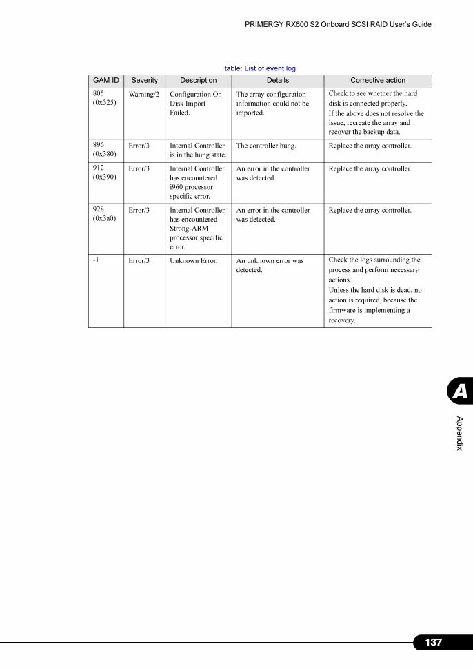
137
PRIMERGY RX600 S2 Onboard SCSI RAID User’s Guide
Appendix
A
805
(0x325)Warning/2 Configuration On
Disk Import
Failed.
The array configuration
information could not be
imported.
Check to see whether the hard
disk is connected properly.
If the above does not resolve the
issue, recreate the array and
recover the backup data.
896
(0x380)Error/3 Internal Controller
is in the hung state.
The controller hung. Replace the array controller.
912
(0x390)Error/3 Internal Controller
has encountered
i960 processor
specific error.
An error in the controller
was detected.
Replace the array controller.
928
(0x3a0)Error/3 Internal Controller
has encountered
Strong-ARM
processor specific
error.
An error in the controller
was detected.
Replace the array controller.
-1 Error/3 Unknown Error. An unknown error was
detected.
Check the logs surrounding the
process and perform necessary
actions.
Unless the hard disk is dead, no
action is required, because the
firmware is implementing a
recovery.
table: List of event log
GAM ID Severity Description Details Corrective action

138
Index
A
Add Logical Drive. . . . . . . . . . . . . . . . . . 85, 89
Administrator . . . . . . . . . . . . . . . . . . . . . . . . 70
Advanced options . . . . . . . . . . . . . . . . . . . . 83
AlarmService . . . . . . . . . . . . . . . . . . . . . . . . 66
B
Background initialize status . . . . . . . . . . . . 108
Background task . . . . . . . . . . . . . . . . . . . . 108
C
Clustering parameters . . . . . . . . . . . . . . . . . 83
Consistency Check . . . . . . . . . . . . 17, 42, 111
Check its progress . . . . . . . . . . . . . . . . 109
Consistency Check Status . . . . . . . . . . . . . 109
Controller options. . . . . . . . . . . . . . . . . . . . . 81
Advanced options. . . . . . . . . . . . . . . . . . 83
Clustering parameters . . . . . . . . . . . . . . 83
Global parameters . . . . . . . . . . . . . . . . . 82
Start up parameters . . . . . . . . . . . . . . . . 83
Window layout . . . . . . . . . . . . . . . . . . . . 82
Controller selection box . . . . . . . . . . . . . . . . 74
Controller View. . . . . . . . . . . . . . . . . . . 75, 101
Hard disk information . . . . . . . . . . . . . . 103
Logical drive information. . . . . . . . . . . . 105
D
Disk Array . . . . . . . . . . . . . . . . . . . . . . . 10, 29
Deleting configuration information . . . . . 39
How to create a configuration. . . . . . . . . 29
E
Edit Configuration . . . . . . . . . . . . . . 85, 93, 94
Enclosure. . . . . . . . . . . . . . . . . . . . . . . . . . . 76
Event . . . . . . . . . . . . . . . . . . . . . . . . . . . . . . 99
Expand Array . . . . . . . . . . . . . . . . . . . . . 85, 90
Expand Capacity . . . . . . . . . . . . . . . 16, 44, 90
Check its progress . . . . . . . . . . . . . . . . 109
Expand Capacity Status . . . . . . . . . . . . . . . 109
F
Foreground initialize status . . . . . . . . . . . . 108
G
GAM . . . . . . . . . . . . . . . . . . . . . . . . . . . 56, 70
Access privileges . . . . . . . . . . . . . . . . . . 70
Exiting . . . . . . . . . . . . . . . . . . . . . . . . . . 72
Initializing a logical drive. . . . . . . . . . . . . 95
Installing. . . . . . . . . . . . . . . . . . . . . . . . . 58
List of error codes . . . . . . . . . . . . . . . . 125
Local logon setting . . . . . . . . . . . . . . . . . 62
Maintenance functions . . . . . . . . . . . . . 111
RAID Assist . . . . . . . . . . . . . . . . . . . . . . 84
Requirements. . . . . . . . . . . . . . . . . . . . . 57
Setting and releasing a spare disk . . . . . 94
Sign on. . . . . . . . . . . . . . . . . . . . . . . . . . 71
Starting. . . . . . . . . . . . . . . . . . . . . . . . . . 71
Tool bar . . . . . . . . . . . . . . . . . . . . . . . . . 79
Uninstalling . . . . . . . . . . . . . . . . . . . . . . 63
Window layout . . . . . . . . . . . . . . . . . . . . 73
GAM Client . . . . . . . . . . . . . . . . . . . . . . . . . 56
Installing. . . . . . . . . . . . . . . . . . . . . . . . . 58
Server group and server settings . . . . . . 80
Uninstalling . . . . . . . . . . . . . . . . . . . . . . 63
GAM ID . . . . . . . . . . . . . . . . . . . . . . . . . . . 125
GAM Server. . . . . . . . . . . . . . . . . . . . . . . . . 56
Installing. . . . . . . . . . . . . . . . . . . . . . . . . 58
Uninstalling . . . . . . . . . . . . . . . . . . . . . . 63
Global Array Manager . . . . . . . . . . . . . . . . . 56
Global Parameters. . . . . . . . . . . . . . . . . . . . 82
Global Status View. . . . . . . . . . . . . . . . . . . . 73
Guest. . . . . . . . . . . . . . . . . . . . . . . . . . . . . . 70
H
Hard Disk
Checking applicability of redundancy . . 117
Displaying sense information . . . . . . . . 107
Formatting . . . . . . . . . . . . . . . . . . . . . . . 51
Logical drive. . . . . . . . . . . . . . . . . . . . . . 11
Physical pack . . . . . . . . . . . . . . . . . . . . . 11
Preventive replacement . . . . . . . . . . . . 117
RAID level . . . . . . . . . . . . . . . . . . . . . . . 10
Replacing. . . . . . . . . . . . . . . . . . . . . . . 114
Status icon . . . . . . . . . . . . . . . . . . . . . . . 76
View the status by WebBIOS . . . . . . . . . 49
Viewing information by Controller View 103
I
Installing
GAM . . . . . . . . . . . . . . . . . . . . . . . . . . . 58
GAM Client . . . . . . . . . . . . . . . . . . . . . . 58
GAM Server . . . . . . . . . . . . . . . . . . . . . . 58

139
PRIMERGY RX600 S2 Onboard SCSI RAID User’s Guide
L
List of GAM error codes . . . . . . . . . . . . . . 125
Log Information Viewer . . . . . . . . . . . . 74, 100
Logical Drive . . . . . . . . . . . . . . . . . . . . . . . . 11
Background initialization . . . . . . . . . . . . 13
Consistency check . . . . . 17, 42, 109, 111
Deleting. . . . . . . . . . . . . . . . . . . . . . . . . 93
Displaying information by Controller View
. . . . . . . . . . . . . . . . . . . . . . . . . . . . 105
Expand array. . . . . . . . . . . . . . . . . . . . . 90
Expand Capacity . . . . . . . . . . . . . . 44, 109
Initialization by WebBIOS . . . . . . . . . . . 13
Initializing . . . . . . . . . . . . . . . . . 13, 40, 95
Rebuild . . . . . . . . . . . . . . . . . . . . . . . . . 14
Status icon . . . . . . . . . . . . . . . . . . . . . . 76
View the status by WebBIOS. . . . . . . . . 47
M
MegaRAID SCSI 320-2E . . . . . . . . . . . . . . 10
N
New Configuration . . . . . . . . . . . . . . . . . . . 85
NVRAM Error Log. . . . . . . . . . . . . . . . . . . 107
P
Patrol Read. . . . . . . . . . . . . . . . . . . . . 17, 109
Check its progress. . . . . . . . . . . . . . . . 109
Patrol Read Status . . . . . . . . . . . . . . . . . . 109
Physical Pack . . . . . . . . . . . . . . . . . . . . . . . 11
Deleting. . . . . . . . . . . . . . . . . . . . . . . . . 37
Expand capacity . . . . . . . . . . . . . . . . . . 16
R
RAID Assist . . . . . . . . . . . . . . . . . . . . . . . . 84
Add logical drive . . . . . . . . . . . . . . . . . . 85
Edit configuration . . . . . . . . . . . . . . . . . 85
Expand array. . . . . . . . . . . . . . . . . . . . . 85
New configuration . . . . . . . . . . . . . . . . . 86
RAID Configuration
Adding a logical drive . . . . . . . . . . . . . . 89
Deleting. . . . . . . . . . . . . . . . . . . . . . . . . 98
New cofiguration . . . . . . . . . . . . . . . . . . 86
Restoring. . . . . . . . . . . . . . . . . . . . . . . . 97
Saving. . . . . . . . . . . . . . . . . . . . . . . . . . 97
RAID Controller. . . . . . . . . . . . . . . . . . . . . 101
Controller View . . . . . . . . . . . . . . . . . . 101
Displaying detailed information . . . . . . 102
RAID Level . . . . . . . . . . . . . . . . . . . . . 10, 122
RAID 1 (Mirroring) . . . . . . . . . . . . . . . . 122
RAID 10 (Mirroring + Striping) . . . . . . . 124
RAID 5 (Striping + Parity) . . . . . . . . . . 123
Rebuild . . . . . . . . . . . . . . . . . . . . . . . . 14, 112
Hot Spare (Standby) . . . . . . . . . . . . . . . .14
Manual Rebuild . . . . . . . . . . . . . . . . . . . .15
Status . . . . . . . . . . . . . . . . . . . . . . . . . .108
Rebuild Status . . . . . . . . . . . . . . . . . . . . . .108
Request sense data . . . . . . . . . . . . . . . . . .107
S
SCSI array controller
Controller options . . . . . . . . . . . . . . . . . .81
Performance . . . . . . . . . . . . . . . . . . . . . .10
Properties . . . . . . . . . . . . . . . . . . . . .25, 81
Sense information. . . . . . . . . . . . . . . . . . . .107
Server group and server settings . . . . . . . . .80
Server selection box . . . . . . . . . . . . . . . . . . .73
Server status icon . . . . . . . . . . . . . . . . . . . . .74
ServerView . . . . . . . . . . . . . . . . . . . . . . . . . .66
Spare Disk . . . . . . . . . . . . . . . . . . . . . . . . . .14
Releasing . . . . . . . . . . . . . . . . . . . . .36, 94
Setting . . . . . . . . . . . . . . . . . . . . . . .35, 94
Start up parameters . . . . . . . . . . . . . . . . . . .83
Status icon
Hard disk. . . . . . . . . . . . . . . . . . . . . . . . .76
Logical drive . . . . . . . . . . . . . . . . . . . . . .76
U
Uninstalling
GAM . . . . . . . . . . . . . . . . . . . . . . . . . . . .63
GAM Client . . . . . . . . . . . . . . . . . . . . . . .63
GAM Server . . . . . . . . . . . . . . . . . . . . . .63
User . . . . . . . . . . . . . . . . . . . . . . . . . . . . . . .70
W
WebBIOS . . . . . . . . . . . . . . . . . . . . . . . .13, 19
Checking a background task . . . . . . . . . .52
Exiting. . . . . . . . . . . . . . . . . . . . . . . . . . .53
Formatting a hard disk . . . . . . . . . . . . . .51
How to start up . . . . . . . . . . . . . . . . . . . .20
Main menu . . . . . . . . . . . . . . . . . . . . . . .23
Viewing the hard disk . . . . . . . . . . . . . . .49
Viewing the logical drive . . . . . . . . . . . . .47
Window layout . . . . . . . . . . . . . . . . . . . .23
Write Back . . . . . . . . . . . . . . . . . . . . . . . . . .12
Write Cache . . . . . . . . . . . . . . . . . . . . . . . . .12
Write Mode . . . . . . . . . . . . . . . . . . . . . . . . . .12
Write Through. . . . . . . . . . . . . . . . . . . . . . . .12

140

• The contents of this manual may be revised without prior notice.
• Fujitsu assumes no liability for damages to third party copyrights or other rights
arising from the use of any information in this manual.
• No part of this manual may be reproduced in any without the prior written
permission of Fujitsu.
PRIMERGY RX600 S2
Onboard SCSI RAID User's Guide
B7FH-3761-01ENZ0-00
Issued on
Issued by
September, 2005
FUJITSU LIMITED
Top Related