


Languages
Pages
Legal


BOEING is a trademark of Boeing Management Company.Copyright © 2009 Boeing. All rights reserved.
On-Orbit Performance of a Triple-Voted, COTS-Based Computer
Keith WilliamsonBoeing Space & Intelligence Systems
This document contains public domain information and technical data approved for public release. The technical data approved forpublic release is authorized for export in accordance with and under the authority of the U.S. Government's International Traffic in Arms Regulations (ITAR) 22 CFR 125.4(b)(13) and Directorate for Freedom of Information and Security Review (DFOISR) 00-S-0818. This document does not contain technical data as defined in the ITAR 22 CFR 120.10
9 December, 2009

Copyright © 2009 Boeing. All rights reserved.
Overview
Boeing Space & Intelligence Systems developed the SPACEWAY® satellite for Hughes Network Systems
Three satellites launched 2005 - 2007SPACEWAY-3 satellite is a key element of the HughesNetIP-over-Satellite Internet service
SPACEWAY payload electronics are based almost exclusively on terrestrial COTS technologies, using architectural approaches to SEU mitigation
Payload Control Computer (PCC) is based on COTS microprocessor, memories, and ASIC technology
Large performance advantages vs. Rad Hard By Process (RHBP) componentsOn-orbit PCCs have accumulated over 20 years of power-on time with zero service-affecting errors due to SEU (or any other source)SPACEWAY success with architectural SEU mitigation is driving current Boeing R&D in fault-tolerant spaceborne computing
2

Copyright © 2009 Boeing. All rights reserved.
SPACEWAY® Satellite PayloadRegenerative (demod/remod) payload with on-board digital signal processor and fast packet switchFull-mesh, single-hop connectivity at up to 16 Mbps per terminal
10 Gbps total capacityMassive frequency reuse via phased array spot beams
112 fixed uplink beams (FDMA/TDMA)24 agile, electronically steered and shaped downlink beams (TDMA) provide 784 microcells on ground
Payload Control Computer
Demod
Demod
Demod
Demod
Fast Packet Switch
Mod
Mod
Mod
Mod
Digital Signal Processor
RF Switch Matrix
Ka-BandDown Conv.
Receive PhasedArray
Antenna
Ka-BandUp
Conv.
Transmit PhasedArray
Antenna
SPACEWAY Communications Payload
SPACEWAY Digital Signal Processor
Channelization (FDM decoding)DemodulationError-correction decodingTDM descramblingPacket switchingTDM formattingRecoding,Remodulation
DSP Hardware Functions
~62 trillion operations/second
3
Copyright © 2009 Boeing. All rights reserved.
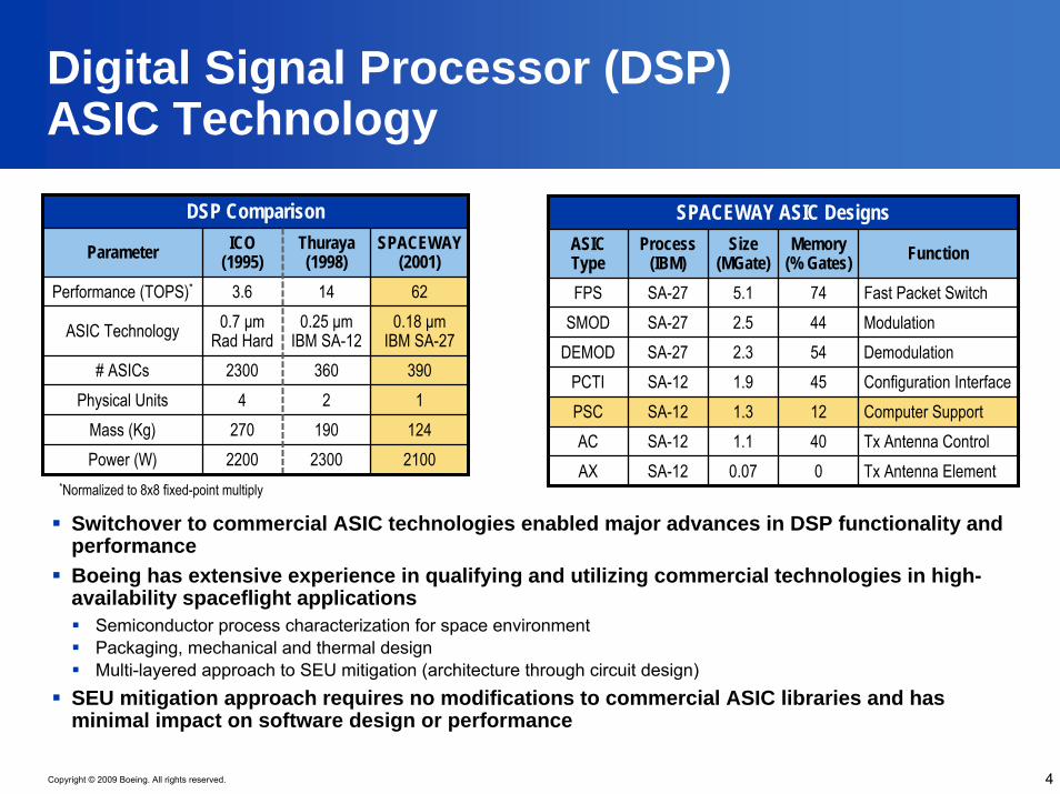
Digital Signal Processor (DSP)ASIC Technology
Switchover to commercial ASIC technologies enabled major advances in DSP functionality and performance Boeing has extensive experience in qualifying and utilizing commercial technologies in high-availability spaceflight applications
Semiconductor process characterization for space environmentPackaging, mechanical and thermal designMulti-layered approach to SEU mitigation (architecture through circuit design)
SEU mitigation approach requires no modifications to commercial ASIC libraries and has minimal impact on software design or performance
SPACEWAY ASIC DesignsASIC Type
Process (IBM)
Size (MGate)
Memory (% Gates) Function
FPS SA-27 5.1 74 Fast Packet SwitchSMOD SA-27 2.5 44 Modulation
DEMOD SA-27 2.3 54 DemodulationPCTI SA-12 1.9 45 Configuration InterfacePSC SA-12 1.3 12 Computer SupportAC SA-12 1.1 40 Tx Antenna ControlAX SA-12 0.07 0 Tx Antenna Element
DSP Comparison
Parameter ICO (1995)
Thuraya (1998)
SPACEWAY (2001)
Performance (TOPS)* 3.6 14 62
ASIC Technology 0.7 μm Rad Hard
0.25 μm IBM SA-12
0.18 μmIBM SA-27
# ASICs 2300 360 390Physical Units 4 2 1
Mass (Kg) 270 190 124Power (W) 2200 2300 2100
*Normalized to 8x8 fixed-point multiply
4

Copyright © 2009 Boeing. All rights reserved.
SPACEWAY® Payload Control Computer (PCC)
Uplink/downlink bandwidth management140K uplink bandwidth requests/allocations per second
User terminal accounting2 million-terminal database
General payload command and control functions
CPU Upsets per
Month *Spacecraft Operator Launch Date
Computer POH
(Master + Slave) Avg Max
2.2 567
2.33.4
SPACEWAY 1 DirecTV Apr 2005
Computer Failures
75,900 Hrs65,700 Hrs35,000 Hrs
0SPACEWAY 2 DirecTV Nov 2005 0SPACEWAY 3 HNS Aug 2007 0
PCC Software FunctionsPowerPC 750LPowerPC
750LPowerPC 750L
128 MB EDAC
SDRAM
128 KB Boot
PROM
Processor Support Chip
(PSC)
Application I/O
Application Memory
(EEPROM)
PCC Master
PowerPC 750LPowerPC
750LPowerPC 750L
128 MB EDAC
SDRAM
128 KB Boot
PROM
Processor Support Chip
(PSC)
PCC Slave
PCI Bus
PCC Hardware Architecture
On-Orbit SEU Performance
*Based on PSC voting logic telemetry5
Copyright © 2009 Boeing. All rights reserved.
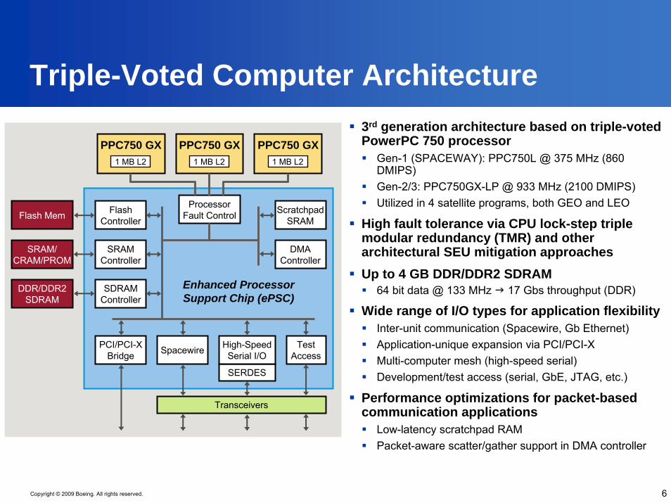
Triple-Voted Computer Architecture
Processor Fault Control Scratchpad
SRAM
DMA Controller
Flash Controller
SRAM Controller
SDRAM Controller
Flash Mem
SRAM/CRAM/PROM
DDR/DDR2SDRAM
SpacewirePCI/PCI-X Bridge
Test Access
SERDES
High-Speed Serial I/O
PPC750 GX1 MB L2
PPC750 GX1 MB L2
PPC750 GX1 MB L2
Transceivers
Enhanced Processor Support Chip (ePSC)
3rd generation architecture based on triple-voted PowerPC 750 processor
Gen-1 (SPACEWAY): PPC750L @ 375 MHz (860 DMIPS)Gen-2/3: PPC750GX-LP @ 933 MHz (2100 DMIPS)Utilized in 4 satellite programs, both GEO and LEO
High fault tolerance via CPU lock-step triple modular redundancy (TMR) and other architectural SEU mitigation approachesUp to 4 GB DDR/DDR2 SDRAM
64 bit data @ 133 MHz 17 Gbs throughput (DDR)
Wide range of I/O types for application flexibilityInter-unit communication (Spacewire, Gb Ethernet)Application-unique expansion via PCI/PCI-XMulti-computer mesh (high-speed serial)Development/test access (serial, GbE, JTAG, etc.)
Performance optimizations for packet-based communication applications
Low-latency scratchpad RAM Packet-aware scatter/gather support in DMA controller
6

Copyright © 2009 Boeing. All rights reserved.
CPU Fault RecoverySoftware controls the response to CPU faults, minimizing impact of recovery actions on system performance
Software schedules CPU “resync” operations to remove detected or latent errors in CPU stateResync can be periodic, on-demand, or bothSPACEWAY example:
– Resync once per 96 ms SPACEWAY “frame” period– 500 μs worst-case resync time; < 0.5% overhead
CPU resync is triggered with a software-controlled interrupt:
1. Interrupt service routine saves “majority” CPU state– CPU registers are saved to main memory– Caches are flushed to main memory
2. All CPUs are hard reset3. Boot code restores CPU registers and “returns”
from the resync interrupt
CPU/Memory SEU Mitigation
Processor Fault Control Scratchpad
SRAM
DMA Controller
Flash Controller
SRAM Controller
SDRAM Controller
Flash Mem
SRAM/CRAM/PROM
DDR/DDR2SDRAM
SpacewirePCI/PCI-X Bridge
Test Access
SERDES
High-Speed Serial I/O
PPC750 GX1 MB L2
PPC750 GX1 MB L2
PPC750 GX1 MB L2
Transceivers
Enhanced Processor Support Chip (ePSC)
7
Cycle-by-cycle majority voting of processor buses
Cycle-by-cycle majority voting of processor buses
Masking logic immediately disables faulted CPU, preventing error propagation
Masking logic immediately disables faulted CPU, preventing error propagation
Strong EDAC codes enable correction of double-device faults
Strong EDAC codes enable correction of double-device faults
Configurable background scrubbing to remove latent errors
Configurable background scrubbing to remove latent errors

Copyright © 2009 Boeing. All rights reserved.
Embedded Computing HardwareTrends & Challenges
NEEDS BARRIERS ENABLERS SOLUTIONS
Continual improvement in system performance
Highly diverse data processing
Performance sensitivity to memory latency & bandwidth
Product size/power constraints
Power impact of increased core frequency
Moore’s Law• Available die area
Advanced design & verification methods
On-chip integration• Memory controllers• Application-specific
accelerators• I/O interfaces
System on Chip (SoC) microprocessor products
Multicore SoCs
Compatible product families
Terrestrial Applications
COTS SoC utilization to reduce program costs
High reliability & availability
• Soft error tolerance
Evolutionary paths to avoid obsolescence issues
Lower real-time determinism due to shared resources
• Multicore!
Challenging verification, validation & certification
Fewer “hooks” for SEU mitigation
Industry cooperation• AVSI study for
aviation applications
Prevalence of SOI technology in SoC products
• Latchup immunity• Lower SEU rates
Aerospace Applications
Multiple approaches being studied for space applications
8
Copyright © 2009 Boeing. All rights reserved.
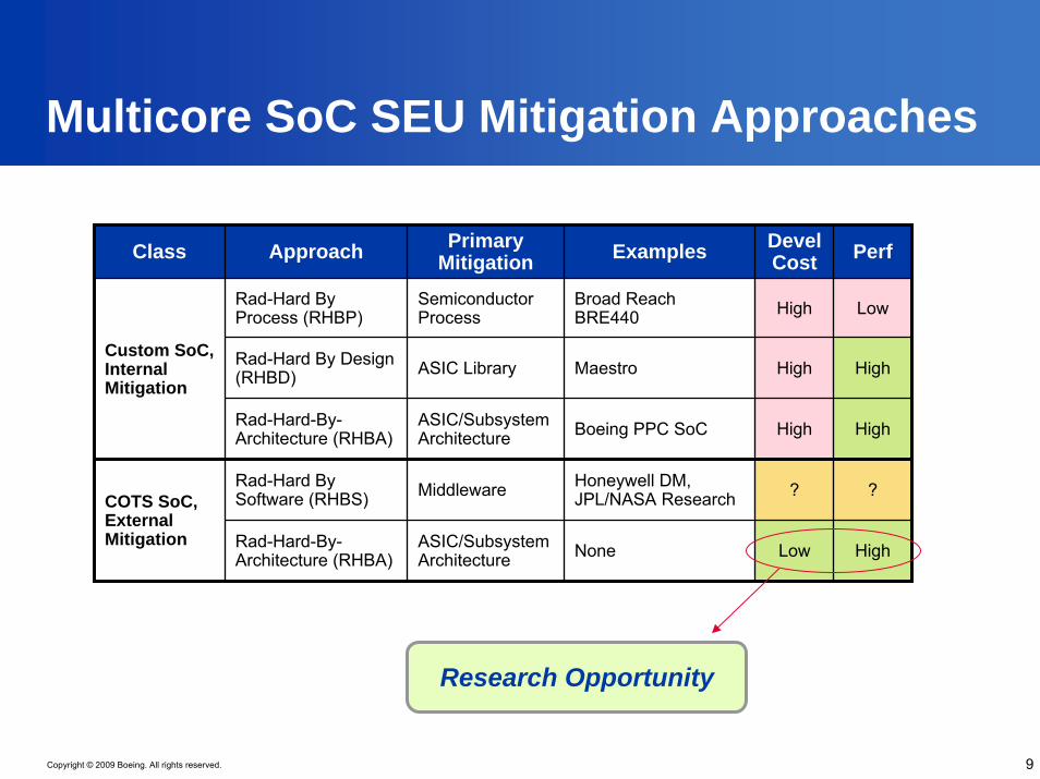
Multicore SoC SEU Mitigation Approaches
Class Approach Primary Mitigation Examples Devel
Cost Perf
Rad-Hard By Process (RHBP)
Semiconductor Process
ASIC Library
ASIC/Subsystem Architecture
Middleware
ASIC/Subsystem Architecture
Broad Reach BRE440 High Low
Rad-Hard By Design (RHBD) Maestro High High
Rad-Hard-By-Architecture (RHBA) Boeing PPC SoC High High
Rad-Hard By Software (RHBS)
Honeywell DM, JPL/NASA Research ? ?
Rad-Hard-By-Architecture (RHBA) None Low High
Custom SoC, Internal Mitigation
COTS SoC, External Mitigation
9
Research Opportunity

Copyright © 2009 Boeing. All rights reserved.
Conclusions
The SPACEWAY® payload computer continues to meet/exceed its mission requirements
20+ accumulated power-on years with 100% service availability
No other deployed spaceflight computer has demonstrated this level of fault tolerance and performance
10
Architectural SEU mitigation approach enables extensive leverage of terrestrial COTS components and technologiesThis approach provides a potential path to achieving much higher levels of performance using COTS multicore SoC technology

Copyright © 2009 Boeing. All rights reserved.
References
[1] Sunderland et al., “Second Generation Mega-gate ASICs for the SPACEWAY Satellite Communications Payload”, NASA Symposium on VLSI Design, May 2003
[2] Bickel, “Fault Tolerant Processing Architecture”, US Patent No. 6,938,183 B2, Boeing, Aug 2005
11

Copyright © 2009 Boeing. All rights reserved.
Contact Information
Keith WilliamsonEngineering Project Manager
Boeing Space & Intelligence SystemsEl Segundo, California(310) [email protected]
12
Top Related