


Languages
Pages
Legal


O I L F I R E D B O I L E R S
THIS MANUAL MUSTREMAIN WITH THEHOUSEHOLDER ONCOMPLETION OFINSTALLATION I.S. EN ISO 9002
I N S T A L L A T I O NC O M M I S S I O N I N GS E R V I C I N G &USER INSTRUCTIONS
S y s t e m R a n g e

CONTENTS
1
FOREWORD1. INTRODUCTION - P. 2 - 3
Health & SafetyFuel SpillageFirst Aid
2. OPERATING INSTRUCTIONS - P. 4 - 52a Boiler controls2b Operating procedure2c Burner lock out
3. INSTALLATION - P. 6 - 83a Standards & Regulations3b Installation in New Zealand and Australia3c Positioning Boiler3d Room Seald Balanced Flues
4. FLUE SYSTEMS - P. 9 - 174a Important notice4b Balanced flue systems4c Concentric flue systems4d Boiler siting regulations & Standards4e Ventilation and Combustion Air
1. Conventional Flue2. Balanced Flue
4.f Domestic Htc. & H.w. Systems electrical supply
5. OIL SUPPLY - P. 18 - 195a Oil storage tank siting5b Flexible oil pipe(s)5c Single pipe system5d Two pipe systems5e Tigerloop single pipe systems
6. COMMISSIONING - P. 206a Procedures6b Handing over
7. SERVICING - P. 217a Recommended service intervals7b The oil tank7c The boiler7d The Burner
8. FAULT FINDING - P. 22 & 239. TECHNICAL SPECIFICATIONS - P. 24 - 30
9a Boiler Dimensions9b Boiler Specifications & Recommendations Etc.9c Oil Burner Performance Specification9d & e Riello Oil Burner Specification & Technical Details9g & i Thermostat Control & Wiring
SYSTEM PART 2.Sealed System & Domestic Heating - Page 31 - 36
SYSTEM PART 3.10. SPARE PARTS - P. 37 - 48
10a Riello RDB burner illustration & parts10b Riello burner illustration & parts10c Pluming parts illustration10d Pluming parts description10e Boiler parts illustration - System Range 50/70 - 70/9010f Boiler parts description - System Range 50/70 - 70/9010g Boiler parts illustration - System Range 90/120 - 120/15010h Boiler parts description - System Range 90/120 - 120/15010i Boiler parts illustration - System Heat Pac 7010j Boiler parts illustration - System Heat Pac 70/9010k Boiler parts illustration - System Heat Pac 90/120 - 120/150
10. RECORDS & REPORTS - P. 49 - 51Commissioning record Page 49Service reports Page 50 & 51
2
FOREWORD 1 INTRODUCTION
This instruction manual is produced for the reference
and guidance of qualified installation engineers. EU
legislation governs the manufacture, operation and
efficiency of all domestic oil boilers. One effect of this
will be that boilers and burners will require to be
supplied as matched units tested and approved to
OFTEC Standard OFS Al00.
FIREBIRD Boilers are full manufacturing members of
OFTEC (Oil Firing Technical Association for the
Petroleum Industry) and are participating in its Boiler
testing and approvals programme to comply with OFS
A100 and EC Efficiency Directive.
Boilers must be installed, commissioned
and serviced by qualified and experienced
OFTEC approved personnel (U.K. only). It
should be noted that it is the
responsibility of the installer to ensure
that the boiler is properly commissioned.
Failure to do so may invalidate the boiler
guarantee and any extended warranty.
All appropriate OFTEC manuals and BS
Standards should be studied and their
requirements adhered to and used in
conjunction with these instructions. This
manual includes a list of some BS
Standards and Building Regulations.
OFTEC is conducting training and registration of
engineers and this is to be commended, as reading of
this manual alone for installation and servicing
procedures cannot replace the critical advantage
provided by training and years of experience.
The Firebird System Boiler Range is based on the ‘S’Range Boilers. All boilers in the range are designedand manufactured to meet all the latest Europeanstandards and the thermal efficiency requirements ofthe Boiler (efficiency) Regulations 1993. All Boilerscan be fitted to a conventional flue or easily adaptedto a room sealed unit by using a Firebird matchedbalanced flue kit.
The control panel can be easily accessed by thesimple removal of four screws, then this assembly canbe pulled forward for access to components.
Clean combustion with kitchen-quiet operation isassured by a highly efficient matching pressure jetburner which produces very low NOx emissions. TheCombi Range is a dedicated sealed system boilerhaving a 12 litre expansion vessel on the 50-70 and70-90 models, on the 90-120 model there is a 14 litreexpansion vessel, system filling kit and 3 bar safetyvalve all fitted within its cabinet.
A drain-off cock is fitted inside the boiler beside theburner and there are flow and return connectionsprovided under top lid of the boiler for connection tothe heating and hot water systems. As all servicing canbe carried out from the front, the boiler many befitted under a kitchen worktop.
GUARANTEE• All Firebird oil Boilers have a 2 yearcomprehensive warranty which extends to5 year on the boiler shell
• The Guarantee card must be fullycompleted and returned to firebird within28 day’s of installation.
• Consumable components, the nozzles andthe oil hose are excluded.
• The terms laid down on the Guaranteemust be adhered to.
NOTE: Some Firebird boilers are suitablefor conversion to gas. Conversion must onlybe undertaken by Firebird approved gastechnicians using a Firebird suppliedconversion kit suitable for the particularboiler.

Safe use of Kerosene and Gas Oil.
These fuels give off a flammable vapour when heatedmoderately. Vapour ignites easily, burns intensely andmay cause explosion. The vapour can follow along atground level for considerable distances from opencontainers and spillages collecting as an explosivemixture in drains, cellars, etc.
Fuels remove natural oils and fats from the skin andthis may cause irritation and cracking of skin. Barriercream containing lanolin is highly recommendedtogether with good personal hygiene.
Gas oil may also cause irreversible damage to healthon prolonged or repeated skin contact.
Always store fuels in a properly constructed andlabelled tank. Always handle fuel in open air or wellventilated space away from sources of ignition andrefrain from smoking.
Always drain fuel using a proper fuel retriever, funnelor mechanical siphon. Never apply heat to a fuel tank,container or pipework. Never siphon fuel throughtube by mouth. If accidentally swallowed contactdoctor immediately and do NOT induce vomiting.Avoid inhaling fuel vapour as this can cause lightheadedness and seriously impair judgement.
3
Under the Consumer Protection Act 1987 andSection 6 of the Health and Safety Act 1974, we arerequired to provide information on substanceshazardous to health.
INSULATION AND SEALSCeramic Fibre, Alumino - Silicone Fibre material areused for boards, ropes and gaskets. Known hazardsare that people may suffer reddening and itching ofthe skin. Fibre entering the eye will cause foreignbody irritation. It may also cause irritation to therespiratory tract.
Precautions should be taken by people with a historyof skin complaints or who may be particularlysusceptible to irritation. High dust levels are onlylikely to arise following harsh abrasion.
Generally, normal handling and use will not givediscomfort. Follow good hygiene practices, washhands before consuming food, drink or using thetoilet.
First Aid - Medical attention should be soughtfollowing eye contact or prolonged reddening of theskin.
The small quantities of adhesives and sealants used inthe product are cured. They present no knownhazards when used in the manner for which they areintended.
1. Switch off all electrical and other ignitionsources.
2. Remove all contaminated clothing to safeguardagainst fire risk and skin damage. Wash affectedskin throughly with soap and water and removeclothing to a safe well ventilated area and allowto air before cleaning.
3. Contain and smother the spill using sand orother suitable non-combustible material.
4. Do not allow fuel to escape into drains or watercourses. If this happens, contact Fire Brigadeand Local Water Authority.
5. Consult local Authority about disposal ofcontaminated soil.
If fuel is accidentally swallowed:-
* Seek medical attention immediately. Do NOTinduce vomiting.
If fuel is splashed into eyes:-
* Wash out with running water for at least tenminutes and seek medical attention.
1 FIRST AID
1 FUEL SPILLAGE
1 SAFETY
1 HEALTH & SAFETYINFORMATION
THIS PRODUCT HAS BEEN DESIGNEDTO THE FOLLOWING STANDARDS:
EMC Directive(Electromagnetic compatibility) 89/336/ECStandards:EN 61000-6-1: Electromagnetic Compatibility GenericStandard - Immunity for residential, commercial andlight industrial environments. (Feb.2001)
EN 61000-6-3: Electromagnetic Compatibility GenericStandard - Emission standard for residential,commercial and light industrial environments.(Feb.2001)
LV Directive(Low voltage) 73/23/EECStandard:IEC 60335-1: Household and similar electricalappliances - Safety (May 2001)
Boiler Efficiency Directive 92/42/EEC Standard:BSEN 304: Oil boilers with forced draft burners.
2 OPERATING INSTRUCTIONS
4
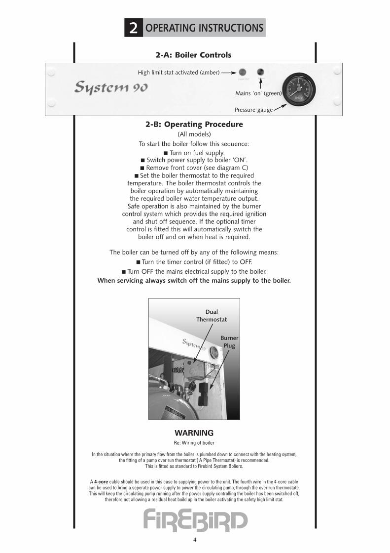
2-B: Operating Procedure(All models)
To start the boiler follow this sequence:� Turn on fuel supply.
� Switch power supply to boiler ‘ON’.� Remove front cover (see diagram C)
� Set the boiler thermostat to the requiredtemperature. The boiler thermostat controls theboiler operation by automatically maintainingthe required boiler water temperature output.
Safe operation is also maintained by the burnercontrol system which provides the required ignition
and shut off sequence. If the optional timercontrol is fitted this will automatically switch the
boiler off and on when heat is required.
The boiler can be turned off by any of the following means:� Turn the timer control (if fitted) to OFF.
� Turn OFF the mains electrical supply to the boiler.When servicing always switch off the mains supply to the boiler.
WARNINGRe: Wiring of boiler
In the situation where the primary flow from the boiler is plumbed down to connect with the heating system,the fitting of a pump over run thermostat ( A Pipe Thermostat) is recommended.
This is fitted as standard to Firebird System Boliers.
A 4-core cable should be used in this case to supplying power to the unit. The fourth wire in the 4-core cablecan be used to bring a seperate power supply to power the circulating pump, through the over run thermostate.This will keep the circulating pump running after the power supply controlling the boiler has been switched off,
therefore not allowing a residual heat build up in the boiler activating the safety high limit stat.
2-A: Boiler Controls
High limit stat activated (amber)
Mains ‘on’ (green)
Pressure gauge
DualThermostat
BurnerPlug
2 OPERATING INSTRUCTIONS
5
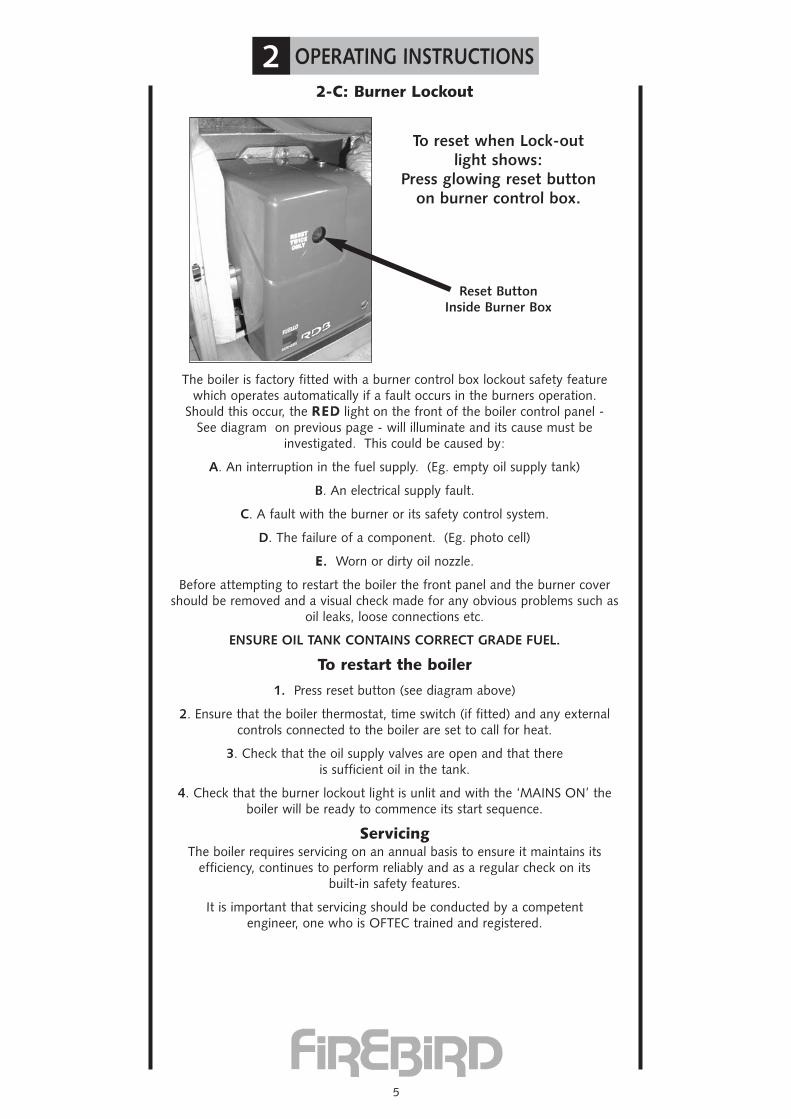
2-C: Burner Lockout
The boiler is factory fitted with a burner control box lockout safety featurewhich operates automatically if a fault occurs in the burners operation.
Should this occur, the RREEDD light on the front of the boiler control panel -See diagram on previous page - will illuminate and its cause must be
investigated. This could be caused by:
A. An interruption in the fuel supply. (Eg. empty oil supply tank)
B. An electrical supply fault.
C. A fault with the burner or its safety control system.
D. The failure of a component. (Eg. photo cell)
EE. Worn or dirty oil nozzle.
Before attempting to restart the boiler the front panel and the burner covershould be removed and a visual check made for any obvious problems such as
oil leaks, loose connections etc.
ENSURE OIL TANK CONTAINS CORRECT GRADE FUEL.
To restart the boiler
1. Press reset button (see diagram above)
2. Ensure that the boiler thermostat, time switch (if fitted) and any externalcontrols connected to the boiler are set to call for heat.
3. Check that the oil supply valves are open and that thereis sufficient oil in the tank.
4. Check that the burner lockout light is unlit and with the ‘MAINS ON’ theboiler will be ready to commence its start sequence.
ServicingThe boiler requires servicing on an annual basis to ensure it maintains its
efficiency, continues to perform reliably and as a regular check on itsbuilt-in safety features.
It is important that servicing should be conducted by a competentengineer, one who is OFTEC trained and registered.
To reset when Lock-outlight shows:
Press glowing reset buttonon burner control box.
Reset ButtonInside Burner Box
3 INSTALLATION
6
3-A: Standards & RegulationsTo ensure the highest standards of installation & safety, it is important
that the boiler be installed in compliance with the following regulationswhere applicable.
All CURRENT editions of the appropriate Building Regulations:-
Part G & J England & WalesPart F, Section III Scotland
Part L Northern IrelandPart J Republic of Ireland
BS 5410 Part 1 1997. Code of practice for Oil Firing Installations.BS 799 Part 5 1987. Specification for Oil Storage Tanks.
BS 4876 1984. Performance requirements for oil burning appliances.BS 5449 1990. Specification for Forced circulation hot water central heating
systems for domestic premises.BS 7074 Part 1 1989. Application, selection and installation of expansion
vessels and ancillary equipment for sealed water systems.BS 5446 1990. Installation of hot water supplies for domestic purposes.
BS 7593 1992. Code of Practice for treatment of water in heating systems.BS 715 1989. Metal flue pipes, fittings, terminals and accessories.
BS 1189 1989. Clay flue linings and flue terminals.BS 4543 part 3 1990. Factory made insulated chimneys for oil fired
appliances.BS 6700. Design, installation, testing and maintenance of Services supplying
water.BS 7671.
Current lEE Regulations.Local Water Undertaking Byelaws.
The Control of Pollution (Oil) Regulations.In addition, the work must comply with OFTEC Installation
Requirements for oil fired boilers and oil storage tanks.
The installer should also be aware of his/her responsibilities under TheHealth and Safety at Work Act. The interests of safety are best served if the
boiler is installed and commissioned by a competent engineer, OFTECtrained and Registered or trained to other recognised standards.
It is the responsibility of installer and everyone concerned with any aspectof installation to ensure that all applicable standards and regulations are
fully adhered to.OFTEC also publish excellent guides including:-
- Safe Working Practices for Oil Firing Technicians'- OFTEC Technical Book Three (Installation requirements for Oil Fired
Boilers and Oil Storage Tanks)- OFTEC Technical Book Four (Domestic Heating Systems)
and it is recommended that these should be adhered to.
Copies of British Standards may be purchased direct from:BSI (Customer Services), 389 Chiswick High Rd.,
London W4 4ALTel.: 0181-9967002 Fax: 0181-9967001
International and EC Standards are also available from above
OFTEC Publications are available from:-
OFTEC,Oil Firing Technical Association,Foxwood House, Dobbs Lane,
Kesgrave, Ipswich.IP5 2QQ
� �

3 INSTALLATION
7
3-B: Installation in New Zealand and Australia
This appliance has been manufactured in compliance with AS1690Domestic Oil Fired appliances Safe Design Code.
This appliance has a current Occupational Safety and Health (OSH)and Environmental Risk Management Association (ERMA)
Clean Air Approval number of 1079/03
This appliance and flue system has been tested by CRL Laboratories inNew Zealand ( Certificate number 07-41180 ) and can be
installed to meet the requirements of AS1691-1985Domestic Oil Fired Appliances Installation.
3.1 This includes suitability for zero clearance installation tocombustible surfaces.
Please ensure that this appliance and flue system is installed to comply withmanufacturers instructions and AS1691-1985 Domestic Oil fired
Appliances Installation.
Please ensure that the appliance is bolted to the floor for seismic restraint.
Firebird recommend the use of Firebird coaxial flue systems to achieve roomsealed operation. However, conventional flue systems are also suitable.
The installation of this appliance and fuel source will require a building consentfrom your local council.
This appliance is tuned to run on diesel fuel.
This appliance must be installed by experienced personnel.Failure to install correctly will invalidate the warranty.The warranty does not cover consequential damages.
If you have any queries with this product,please consult the distributor in New Zealand
Central Heating New Zealand Ltd11 Parkhouse Road
Christchurch0064 3357 1233
www.centralheating.co.nz

3 INSTALLATION
8
3-C: Positioning Boiler
Ensure that adequate clearance is available for makingthe water and flue connections.
As the boiler is serviced from the front,no headroom clearance is necessary but a clearance of 750mm must be
available at the front of the boiler.
No special hearth is required as the boiler is fully insulated, but the floormust be level and capable of supporting the weight of the boiler and its
water content.
Sound levels must also be a consideration. Whilst the Firebird Combi Rangeare one of the quietest boilers on the market, some householders areparticularly sensitive and the following points should be considered:
1. Tiled surfaces in a small room will amplify noise - particularly if the wallconstruction is hollow.
2. If a conventional flue passes through a bedroom it is capable oftransmitting noise.
3. Low level balanced flue terminals can produce exhaust noise on theoutside terminal and this should be considered when siting near adjacent
property.
4. The Firebird low level concentric flue kit has been specifically designedfor Firebird’s indoor boilers. The use of third party low level flue kits
is not recommended and may affect its warranty.
Allow a 25mmm clearance aroundthe flue from combustible surface.
Seal with flange or silicon toprevent ingress of moistureand combustion gas
25mmm 25mmm
Allow a 25mmm clearance aroundthe boiler from combustible surface.
4 FLUE SYSTEMS
9
4-A: Important NoticeBecause of the improved efficiencies of boilers under E.U. Efficiency requirements and
OFT A100 Standard, it is necessary to pay extra special attention to flues and chimneys.The improved efficiency figures achieved by modern oil boilers are attained by using
more of the heat (higher temperatures) heretofore allowed into flues and chimneys. Thispreviously wasted heat helped to keep bad and poorly operating and often uninsulatedflues and chimneys from condensing and causing problems. Please be fully aware of this
when replacing an existing boiler. An old and poorly operating flue may need to bereplaced to take full advantage of improved efficiencies and to avoid flue gases
condensing and appearing as white water vapour (pluming) at flue (chimney) outlet.
New flues and chimneys should be properly insulated and constructed to preventcondensation and draughting problems. Every individual concerned with any aspect ofinstallation should be aware of the foregoing and should have full knowledge of and
work to European, National and Local Govt. Standards and Buildingand Installation Regulations.
These manufactures instructions must not in any way be mis-interpreted as over-ridingthe above or any statutory regulations. It is absolutely essential that the boiler is properly
installed so that NO FLUE GASES can enter the building at any time. Flue pipes shouldbe safely sealed into the wall to prevent flue gases re-entering room or building
Refer also to page 16.
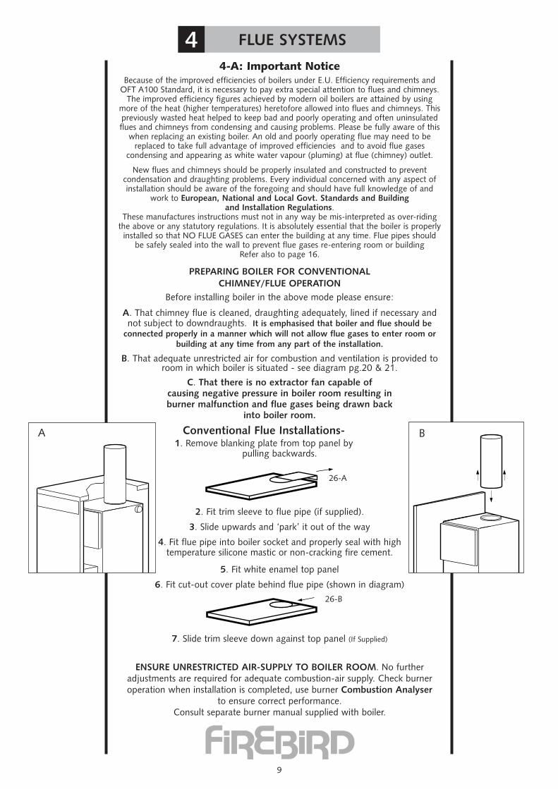
PREPARING BOILER FOR CONVENTIONALCHIMNEY/FLUE OPERATION
Before installing boiler in the above mode please ensure:
A. That chimney flue is cleaned, draughting adequately, lined if necessary andnot subject to downdraughts. It is emphasised that boiler and flue should be
connected properly in a manner which will not allow flue gases to enter room orbuilding at any time from any part of the installation.
B. That adequate unrestricted air for combustion and ventilation is provided toroom in which boiler is situated - see diagram pg.20 & 21.
C. That there is no extractor fan capable ofcausing negative pressure in boiler room resulting inburner malfunction and flue gases being drawn back
into boiler room.
Conventional Flue Installations-1. Remove blanking plate from top panel by
pulling backwards.
2. Fit trim sleeve to flue pipe (if supplied).
3. Slide upwards and ‘park’ it out of the way
4. Fit flue pipe into boiler socket and properly seal with high temperature silicone mastic or non-cracking fire cement.
5. Fit white enamel top panel
6. Fit cut-out cover plate behind flue pipe (shown in diagram)
7. Slide trim sleeve down against top panel (If Supplied)
ENSURE UNRESTRICTED AIR-SUPPLY TO BOILER ROOM. No further adjustments are required for adequate combustion-air supply. Check burneroperation when installation is completed, use burner Combustion Analyser
to ensure correct performance.Consult separate burner manual supplied with boiler.
B
26-A
26-B
A
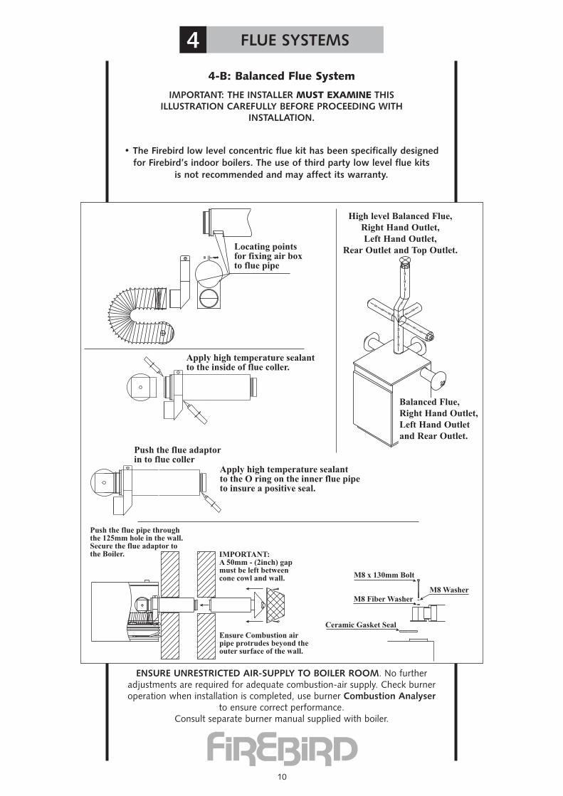
4-B: Balanced Flue System
IMPORTANT: THE INSTALLER MUST EXAMINE THISILLUSTRATION CAREFULLY BEFORE PROCEEDING WITH
INSTALLATION.
ENSURE UNRESTRICTED AIR-SUPPLY TO BOILER ROOM. No furtheradjustments are required for adequate combustion-air supply. Check burneroperation when installation is completed, use burner Combustion Analyser
to ensure correct performance.Consult separate burner manual supplied with boiler.
4 FLUE SYSTEMS
10
Locating pointsfor fixing air boxto flue pipe
Apply high temperature sealantto the inside of flue coller.
Push the flue adaptorin to flue coller
Apply high temperature sealantto the O ring on the inner flue pipeto insure a positive seal.
Push the flue pipe throughthe 125mm hole in the wall.Secure the flue adaptor tothe Boiler. IMPORTANT:
A 50mm - (2inch) gapmust be left betweencone cowl and wall.
Ensure Combustion airpipe protrudes beyond theouter surface of the wall.
M8 x 130mm Bolt
M8 Fiber Washer
Ceramic Gasket Seal
M8 Washer
GAS
GAS
GAS
GAS
GAS
GAS
GAS
GAS
GAS
GASGAS
GAS
GAS
GAS
GAS
GAS
High level Balanced Flue,Right Hand Outlet,Left Hand Outlet,
Rear Outlet and Top Outlet.
Balanced Flue,Right Hand Outlet,Left Hand Outletand Rear Outlet.
• The Firebird low level concentric flue kit has been specifically designedfor Firebird’s indoor boilers. The use of third party low level flue kits
is not recommended and may affect its warranty.
4 FLUE SYSTEMS
11
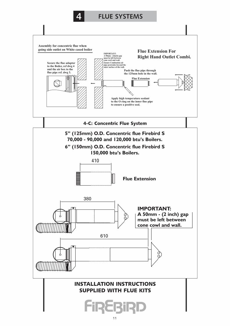
INSTALLATION INSTRUCTIONSSUPPLIED WITH FLUE KITS
5” (125mm) O.D. Concentric flue Firebird S70,000 - 90,000 and 120,000 btu’s Boilers.
6” (150mm) O.D. Concentric flue Firebird S150,000 btu’s Boilers.
IMPORTANT:A 50mm - (2 inch) gapmust be left betweencone cowl and wall.
Push the flue pipe throughthe 125mm hole in the wall.
IMPORTANT:A 50mm - (2inch) gapmust be left betweencone cowl and wall.
Ensure Combustion airpipe protrudes beyond theouter surface of the wall.
Apply high temperature sealantto the O ring on the inner flue pipeto ensure a positive seal.
Secure the flue adaptorto the Boiler, ref dwg 4and the air box to theflue pipe ref. dwg 3.
Flue Extension
Assembly for concentric flue when
going side outlet on White cased boiler Flue Extension For
Right Hand Outlet Combi.
Flue Extension
4-C: Concentric Flue System
4 FLUE SYSTEMS
12
Sli
mli
ne
Hea
t H
ac
(B.)
(D.)
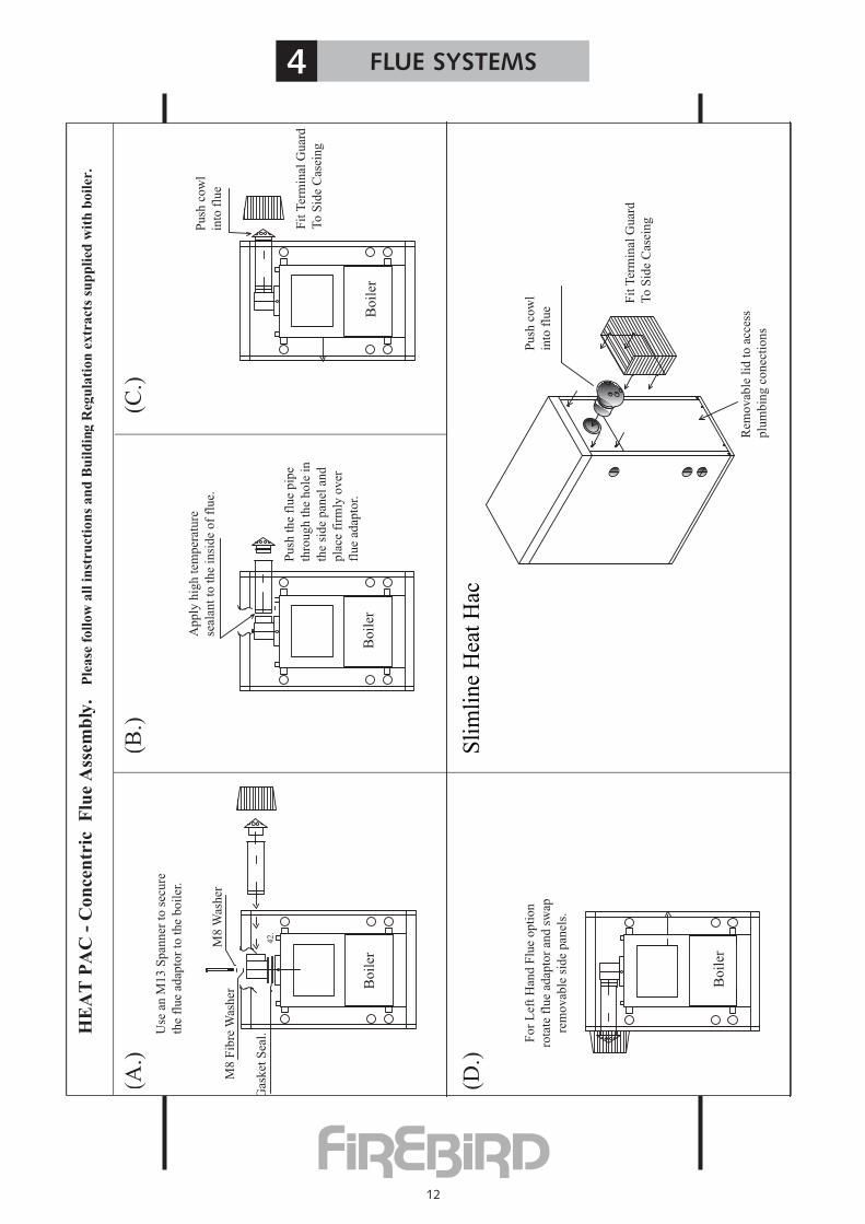
HE
AT
PA
C -
Con
cen
tric
F
lue
Ass
emb
ly.
Ple
ase
foll
ow
all
in
stru
ctio
ns
an
d B
uil
din
g R
egu
lati
on
extr
act
s su
pp
lied
wit
h b
oil
er.
42.
(A.)
M8
Fib
re W
ash
er
Gas
ket
Sea
l.
M8
Was
her
Boil
er
Use
an
M1
3 S
pan
ner
to
sec
ure
the
flue
adap
tor
to t
he
boil
er.
Ap
ply
hig
h t
emp
erat
ure
seal
ant
to t
he
insi
de
of
flue.
Pu
sh t
he
flu
e p
ipe
thro
ug
h t
he
ho
le i
n
the
sid
e p
anel
an
d
pla
ce f
irm
ly o
ver
flue
adap
tor.
Boil
er
(C.)
Boil
er
Pu
sh c
ow
l
into
flu
e
Fit
Ter
min
al G
uar
d
To
Sid
e C
asei
ng
Fo
r L
eft
Han
d F
lue
op
tio
n
rota
te f
lue
adap
tor
and
sw
ap
rem
ov
able
sid
e p
anel
s.
Boil
er
Pu
sh c
ow
l
into
flu
e
Fit
Ter
min
al G
uar
d
To
Sid
e C
asei
ng
Rem
ovab
le l
id t
o a
cces
s
plu
mbin
g c
onec
tions

4 FLUE SYSTEMS
13

4 FLUE SYSTEMS
14
4-D Balanced Flue Siting
Notes: 1. The terminal should be positioned to avoid combustionproducts entering the building or accumulating in stagnantpockets around buildings.
2. The terminal must be protected by a guard if it is less than 2 metres above ground level or in a position where any person has access to it (i.e. a balcony).
3. A heat protection shield should be fitted if the terminal is less than 850mm from a plastic or painted gutter or less than 450mm from painted eaves.
Always check for any Building Regulations amendments which mayhave been issued after the publication of this manual
A. Below a gutter orsanitary pipework.
B. Horizontal fromopening, airbrick,window etc.
C. Above ground orbalcony level.
D. Below eaves orbalcony
E. From an internalor external corner.
F. From a terminalfacing the terminal.
G. From a surfacefacing the terminal.
H. Vertical fromterminals onthe same wall.
I. Horizontal fromterminals on thesame wall.
J.Below an opening, airbrick, window etc.K. From vertical sanitary pipework.L. Vertical flue from wall.
Book three Nov. 1997
A B C D E F G H I J K
England & Wales 1991 - 600 - - 600 - - - - 600 -
Scotland 1990 Balanced* 600 - 600 600 600 600 600 1500 600 600 600Low level* 1000 - 600 1000 600 600 600 1500 600 600 1000
Northern Ireland 1994 - 600 - - 600 - - - - 600 -
Republic of Ireland 1997 - 600 - - 600 - - - - 600 -
*Where the terminal is within 1 metre of any plastic material, such material should be protected from theeffects of combustion products of fuel. There are additional general requirements in most Regulations and Standards that the flue must be positioned so that it does not cause a nuisance and permits the dispersal of
combustion products.
NOTE: The Buildings Regulations clearances shown above are minimum allowed. Account shouldalso be taken of prevailing site conditions, as the above minimums may in certain circumstances
need to be increased. If in doubt contact manufacturer for advice.
See note at foot of page
Building Regulations
� �

15
Minimum distances to terminals in millimetres as measured from top of the chimneyor the rim of a low level discharge opening
A Directly below an opening, air brick, window etc 600B Horizontally to an opening, air brick, window etc 600C Below a gutter, eaves or balcony with protection 75D Below a gutter or a balcony without protection 600E From vertical sanitary pipework 300F From an internal or external corner 300G Above ground or balcony level 300H From a surface or boundary facing the terminal 600J From a terminal facing the terminal 1200K Vertically from a terminal on the same wall 1500L Horizontally from a terminal on the same wall 750M Above the highest point of an intersection with the roof 600N From a vertical structure on the side of the terminal 7500 Above a vertical structure less than 750mm from the side of the terminal 600P From a ridge terminal to a vertical structure on the roof 1500
These notes form an integral part of the information shown above.1. Terminals should be positioned so as to avoid products of combustion accumulating in stagnant pockets
around the building or entering into buildings.2. Vertical structure in N, 0 and P include tank or lift rooms, parapets, dormers etc.3. Terminating positions A to L are only permitted for appliances that have been approved for low level flue
discharge when tested to OFS A1OO or A1O1.4. Terminating positions must be at least 1.8 metres distant from an oil storage tank unless a wall with at least
30 mins fire resistance and extending 300mm higher and wider than the tank is provided between the tank and the terminating position.
5. Where a flue is terminated less than 6OOmm away from a projection above it and the projection consistsof plastic or has a combustible or painted surface, then a heat shield of at least 750mm wide should befitted to protect these surfaces.
6. For terminals used with vapourising burners, a horizontal distance of at least 2300mm is required between the terminal and the roof line.
7. If the lowest part of the terminal is less than 2 metres above the ground, balcony, flat roof or other place to which any person has access, the terminal must be protected by a guard.
4 FLUE SYSTEMS
Clearances advised by the British Standards for Open,and Balanced Flues fitted to Oil Fired Boilers
4-D

4 FLUE SYSTEMS
16
4-E Ventilation and Combustion Air
1. Conventional Flue Boilers
An adequate supply of combustion and ventilation air is essential forefficient and safe boiler operation and the openings for this should be
positioned to cause least possible draught, with no possibility of beingaccidentally blocked.
Please note: The British Standard Code of Practice for Oil Firing BS5410:Part 1, requires a permanent air inlet opening of
550mm2 per kW (above 5 kW)of boiler rated output. (Note: 1kW = 3412 Btu/h).
Also, when the boiler is installed in a compartment or confined space,ventilation openings are required to ventilate and to avoid overheating in
the boiler area.
FULL TEXT of both BS 5410 Part 1: 1997 and appropriate BuildingRegulations for each country should be obtained and fully applied
N.B. Please Carefully Note:A. For boiler installations in domestic garages in Scotland, Part F of
Building Regulations permits only Room Sealed appliances to be used (Ref.OFTEC Bk. Three May 1999 page 1 (18).
B. Technical annex T1/127 to OFTEC Book Three, May 1999 page 2(19) Para. 1, 2 states “In Scotland and the Republic of Ireland only Room
Sealed Balanced Flue Appliances can be used in thatlocation” (i.e. domestic garages).
DefinitionsCombustion Air : Air required directly by boiler oil burner for combustion
process.Ventilation Air : Air required in room for ventilation, cooling, etc. and to
promote a healthy living environment.
Conventional open flue (a) or open flue low level discharge (b)
Combustion & Ventilation air supply for conventionalopen flue boilers
The figures shown are free areas of grilles in mm2 per kw of appliance rating (output).
� �
� �
4 FLUE SYSTEMS
17
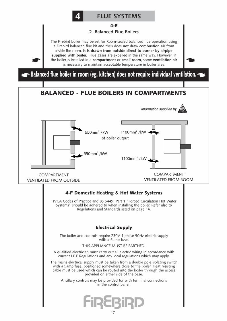
4-E2. Balanced Flue Boilers
The Firebird boiler may be set for Room-sealed balanced flue operation usinga Firebird balanced flue kit and then does not draw combustion air frominside the room. It is drawn from outside direct to burner by airpipe
supplied with boiler. Flue gases are expelled in the same way. However, ifthe boiler is installed in a compartment or small room, some ventilation air
is necessary to maintain acceptable temperature in boiler area
4-F Domestic Heating & Hot Water Systems
HVCA Codes of Practice and BS 5449: Part 1 “Forced Circulation Hot WaterSystems” should be adhered to when installing the boiler. Refer also to
Regulations and Standards listed on page 14.
Electrical Supply
The boiler and controls require 230V 1 phase 50Hz electric supplywith a 5amp fuse.
THIS APPLIANCE MUST BE EARTHED.
A qualified electrician must carry out all electric wiring in accordance withcurrent I.E.E Regulations and any local regulations which may apply.
The mains electrical supply must be taken from a double pole isolating switchwith a 5amp fuse, positioned somewhere close to the boiler. Heat resistingcable must be used which can be routed into the boiler through the access
provided on either side of the base.
Ancillary controls may be provided for with terminal connectionsin the control panel.
Balanced flue boiler in room (eg. kitchen) does not require individual ventilation.� �
� �
BALANCED - FLUE BOILERS IN COMPARTMENTS

5 OIL SUPPLY
18
• This boiler burner is factory set to use 35-second Gas Oil
5-A Oil Storage Tank SitingConsult OFTEC Manual
It is very unlikely that a fire should start from a domestic oil tank,however it does need to be protected from a fire which may originate
in a building nearby. For this reason, the tank should be located at least1.8 metres from any building and no closer than 760mm from any
boundary. If it must be closer than 1.8 metres, the building wallshould not have any openings other than ventilation openings. In addition,
the wall should have a half hour resistance to an internal fire andextend 1.8 metres from any part of the tank.
A non-combustible radiation barrier is an alternative but this must meet therequirements of BS 5410 Part 1: 1994, “clause 28” Section 6.4.
Steel tanks must be mounted on brick or block piers with a waterproofmembrane between the piers and tank.
Polyethylene tanks do not need pier supports and may be mounted on anyflat surface which can support the weight of the tank and its contents. They
also do not corrode and never require painting.
Oil storage tanks should not be sited close to boiler flue outlets.
Do not allow household waste or hot ashes container in vicinity of oilstorage tank or boiler flue outlet.
5-B Flexible Oil Pipe(s)A flexible burner oil hose is supplied with the boiler.
Please note: A filter must not be fitted inside the boiler and all joints inthe oil line must be oil-tight. Soldered joints are not permissible.
Before connecting to the boiler always flush the complete oil supplyline and ensure that oil supply is completely clean and free of any dirt
or foreign matter.
5-C Single Pipe SystemWhere installations have the bottom of the tank above the oil burner, a
single pipe system may be used.The oil burner should then be set for singlepipe operation - See also manufacturers oil burner manual
� �
5 OIL SUPPLY
19
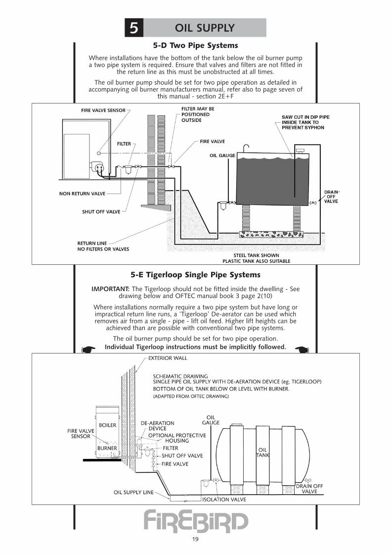
5-D Two Pipe Systems
Where installations have the bottom of the tank below the oil burner pumpa two pipe system is required. Ensure that valves and filters are not fitted in
the return line as this must be unobstructed at all times.
The oil burner pump should be set for two pipe operation as detailed inaccompanying oil burner manufacturers manual, refer also to page seven of
this manual - section 2E+F
5-E Tigerloop Single Pipe Systems
IMPORTANT: The Tigerloop should not be fitted inside the dwelling - Seedrawing below and OFTEC manual book 3 page 2(10)
Where installations normally require a two pipe system but have long orimpractical return line runs, a ‘Tigerloop’ De-aerator can be used whichremoves air from a single - pipe - lift oil feed. Higher lift heights can be
achieved than are possible with conventional two pipe systems.
The oil burner pump should be set for two pipe operation.Individual Tigerloop instructions must be implicitly followed.� �

6 COMMISSIONING
20
Note: Commissioning must be carried out by aOFTEC qualified service engineer. (U.K. Only)
It should be noted that it is the responsibility of the installer to ensurethat the boiler is properly commissioned. Failure to do so mayinvalidate the boiler guarantee and any extended warranty.
6-A: Procedures
1. Oil Tank
The installation of the oil tank and supply line should comply with all theinstructions shown earlier in this manual. Consult OFTEC Manual - Book
No. 3, Section 2.
If a single supply line is used ensure that the bottom of the tank is abovethe burner. A two pipe system should be used where the level of the oil in
the tank may fall below the level of the oil burner pump.
Check and ensure correct grade fuel oil has been supplied.
2. The Burner
A Tigerloop single pipe system may also be used in low-level tankinstallations. See page 21 Section 5. Please flush out oil pipe by drawing offsome oil before connecting fuel pipe to burner - otherwise there is a danger
of grit and dirt being forced into the burner pump, resulting in pumpblockage, damage and ‘lock-out’
3. The Boiler
A. Switch off the power supply, ensure that the boiler and system is full ofwater, all valves are open and that installation conforms with all Standards,
Regulations and Instructions.
B. Check that boiler baffles are correctly positioned.
C. Check the oil supply by disconnecting the oil supply hose at the burnerand running off a quantity to ensure it is free from air. then bleed air from
burner pump. Refer to section 2, page 7, sketch C, Item-E.
D. If fitted, check that the time switch is ‘ON’ and that both room andboiler thermostats are calling for heat.
E. Reconnect electrical supply and the boiler should start. If the burnerlock-out activates, this suggests air in the pump. Wait a minute or so and
try again. If lock-out occurs again, air must be bled from the pump pressuregauge connection point once more.
F. View the burner flame through the sight glass - it should be brightcream/yellow without any sign of smoke.
G. Run the boiler for about fifteen minutes then take a CO2 reading andadjust as necessary.
6-B: Handing OverA thorough check of the system should be made, then the householder
should receive a clear and concise demonstration of the boileroperation and any system controls.
This manual and burner manufacturers manual plus any otherinstructions should be handed over to the user, the guarantee cardshould be completed and posted, and the user advised about the
importance of annual servicing.Commissioning Record - Page 54 - should be completed and a copy
kept in engineers file.
7 SERVICING
21
Note: Servicing must be carried out by aOFTEC qualified engineer. (U.K. Only)
7-A: Recommended Service Intervals
28 second oil Once annually35 second oil Once annually
Before carrying out a service it is recommended that the followingis checked:
A). Smoke
B). CO2
C). The flue gas temperature
D). Oil pressure
E). Ensure flue is unrestricted & operating properly
At the same time check for oil and combustion leaks. Advance to serviceONLY after ensuring that both electric and oil supply to boiler is
disconnected.
7-B: The Oil TankDraw off any accumulated water and sludge from the tank by opening the
drain cock. Turn off the oil supply and remove the filter bowl, then wash theelement clean with kerosene.
7-C: The BoilerRemove combustion access door for access to baffles and to
clean heat exchanger.
Check insulation sealing and its silver foil lining in combustion access door -replacing when necessary. When refitting this door be careful not to dam-
age the foil and insulation by over tightening.
7-D: The BurnerCheck performance of oil-nozzle and replace as necessary.
Ensure correct specification replacement nozzle is used.
Check all oil filters and replace as necessary.
Remove burner and clean blast tube and ensure that airways are clear.
Ensure electrodes are clean, dry, not broken and are set as per burner speci-fications.
Clean fan and photocell.
Once again check flexible oil lines and connections for damage orleaks, replace as necessary.
Combustion Check
Carry out combustion analysis and ensure that boiler is performing to speci-fication outlined in manual. Flue conditions may cause deviation from these
figures.
Always kkeeeepp ccaarreeffuull rreeccoorrdd of flue gas analysis resultsincluding any verbal and written advice to customer (householder).
Always check carefully for restricted or blocked flue. If possible recordCCOO lleevveellss and advise customer of need to keep boiler room well
ventilated.
� �
� �

8 FAULT FINDING
22

8 FAULT FINDING
23
T
Repa
ir or
Repl
ace
Oil P
ump
r
No
9 TECHNICAL SPECIFICATION
24
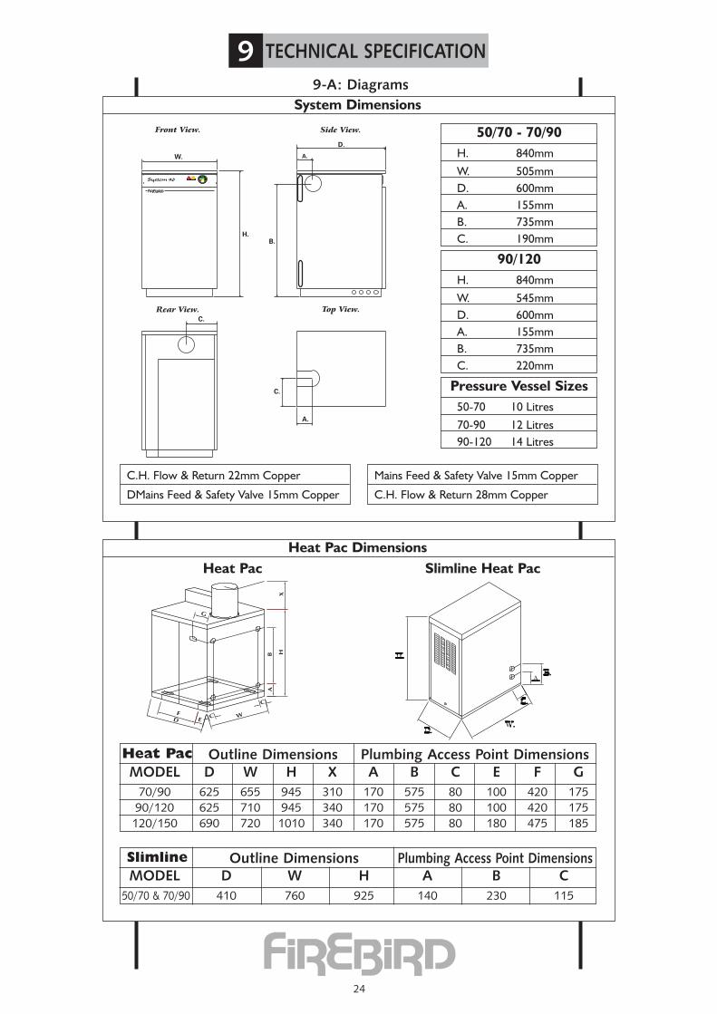
9-A: Diagrams
C.
A.
B.
D.
A.
H.
W.
C.
Rear View. Top View.
Front View. Side View.
System 90
System Dimensions
C.H. Flow & Return 22mm Copper
DMains Feed & Safety Valve 15mm Copper
Mains Feed & Safety Valve 15mm Copper
C.H. Flow & Return 28mm Copper
Heat Pac Dimensions
MODEL D W H X A B C E F G70/90 625 655 945 310 170 575 80 100 420 17590/120 625 710 945 340 170 575 80 100 420 175120/150 690 720 1010 340 170 575 80 180 475 185
Heat Pac Outline Dimensions Plumbing Access Point Dimensions
MODEL D W H A B C50/70 & 70/90 410 760 925 140 230 115
Slimline Outline Dimensions Plumbing Access Point Dimensions
Heat Pac Slimline Heat Pac
H. 840mm
W. 505mmD. 600mmA. 155mmB. 735mmC. 190mm
50/70 - 70/90
H. 840mm
W. 545mmD. 600mmA. 155mmB. 735mmC. 220mm
90/120
50-70 10 Litres
70-90 12 Litres90-120 14 Litres
Pressure Vessel Sizes
25
9 TECHNICAL SPECIFICATION
9-B: Technical Specifications and Recommendations
Heat Output 50-120,000 Btu/HrElectricity Supply 230 v - Boiler~50 Hz
To be fused at 5 ampSystem Pipe Connections (on boiler)Heating Flow 22 mm (28mm - 90-120,00 Btu/Hr)Heating Return 22 mm (28mm - 90-120,00 Btu/Hr)Mains Cold Water Boilerconnection for filling loop 15 mmSafety pressure Relief ValveOutlet 15 mmAll Copper Tube connections: BS 2871 Copper Tube
Pressure Jet Oil Burner Riello RDB or Ecoflam Flair or Bentone Sterling
Circulating Pumps Grundfos UPS 25/60Flue Pipe ConnectionConventional Flue Socket To take tail piece for 4”(100mm) & 5”(125mm)
S/S Flue PipeBalanced Flue Assembly 5”(125mm) Concentric FlueWeight (Dry) - Incl. Pallet 50-70btu’s - 160 Kg
70-90btu’s - 162 Kg90-120btu’s - 177 Kg
Water Content - Total 50-70btu’s - 59 Litres70-90btu’s - 59 Litres90-120btu’s - 68 Litres
ThermostatsBoiler Central heating Control(Adjustable) 65˚C - 85˚CBoiler Safety Limit 110˚CBoiler integral ExpansionVessel nominal capacity 10, 12 & 14 Litres pre-charged to 1 BarHeating System (Sealed) Fit in accordance with BS 7074
Part I, BS 5449, OFTECStandards, etc.
Max. Operating Pressure 2.5 Bar (Follow all BS & OFTEC Standards)Max. System Pressure (Cold) 1.5 Bar Min. System Pressure (Cold) 0.5 Bar + 0.3 BarBoiler Test Pressure 4.5 BarSafety Valve Operating Pressure 3 Bar Heating System Pressure Gauge(mains supply excepted) 0 - 6 Bar RangeFlue Draught Reqd.(Conventional Flue) Min: 0.040 In WG
Max: 0.15 ln WGWater side resistance-10˚C Diff 26.8 ins WG
-20˚C Diff 8.6 ins WG
9 TECHNICAL SPECIFICATION
26
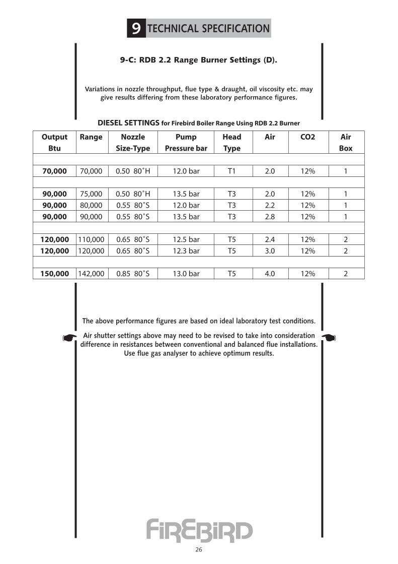
9-C: RDB 2.2 Range Burner Settings (D).
The above performance figures are based on ideal laboratory test conditions.
Air shutter settings above may need to be revised to take into considerationdifference in resistances between conventional and balanced flue installations.
Use flue gas analyser to achieve optimum results.
Variations in nozzle throughput, flue type & draught, oil viscosity etc. maygive results differing from these laboratory performance figures.
��
DIESEL SETTINGS for Firebird Boiler Range Using RDB 2.2 Burner
Output Range Nozzle Pump Head Air CO2 Air
Btu Size-Type Pressure bar Type Box
70,000 70,000 0.50 80˚H 12.0 bar T1 2.0 12% 1
90,000 75,000 0.50 80˚H 13.5 bar T3 2.0 12% 1
90,000 80,000 0.55 80˚S 12.0 bar T3 2.2 12% 1
90,000 90,000 0.55 80˚S 13.5 bar T3 2.8 12% 1
120,000 110,000 0.65 80˚S 12.5 bar T5 2.4 12% 2
120,000 120,000 0.65 80˚S 12.3 bar T5 3.0 12% 2
150,000 142,000 0.85 80˚S 13.0 bar T5 4.0 12% 2
9 TECHNICAL SPECIFICATION
27
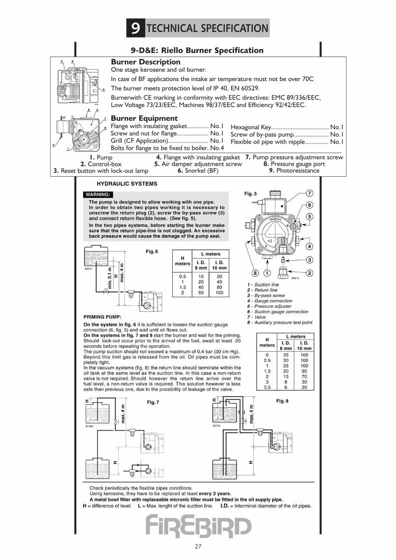
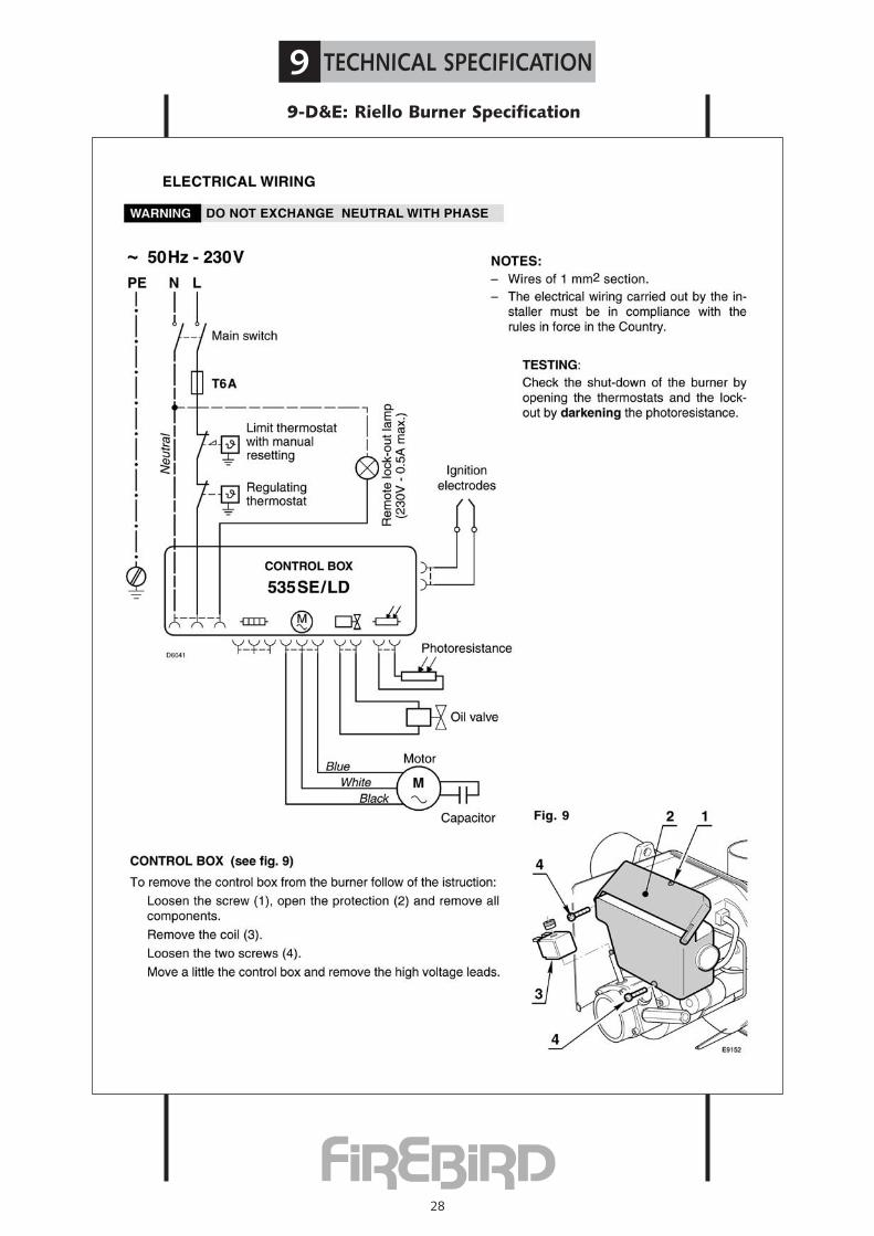
9-D&E: Riello Burner SpecificationBurner DescriptionOne stage kerosene and oil burner.In case of BF applications the intake air temperature must not be over 70CThe burner meets protection level of IP 40, EN 60529.Burnerwith CE marking in conformity with EEC directives: EMC 89/336/EEC,Low Voltage 73/23/EEC, Machines 98/37/EEC and Efficiency 92/42/EEC.
7. Pump pressure adjustment screw8. Pressure gauge port
9. Photoresistance
1. Pump2. Control-box
3. Reset button with lock-out lamp
4. Flange with insulating gasket5. Air damper adjustment screw
6. Snorkel (BF)
Burner EquipmentFlange with insulating gasket............. No.1Screw and nut for flange................... No.1Grill (CF Application)........................ No.1Bolts for flange to be fixed to boiler..No.4
Hexagonal Key................................... No.1Screw of by-pass pump..................... No.1Flexible oil pipe with nipple.............. No.1
9 TECHNICAL SPECIFICATION
28
9-D&E: Riello Burner Specification
9 TECHNICAL SPECIFICATION
29
9-D&E: Riello Burner Specification
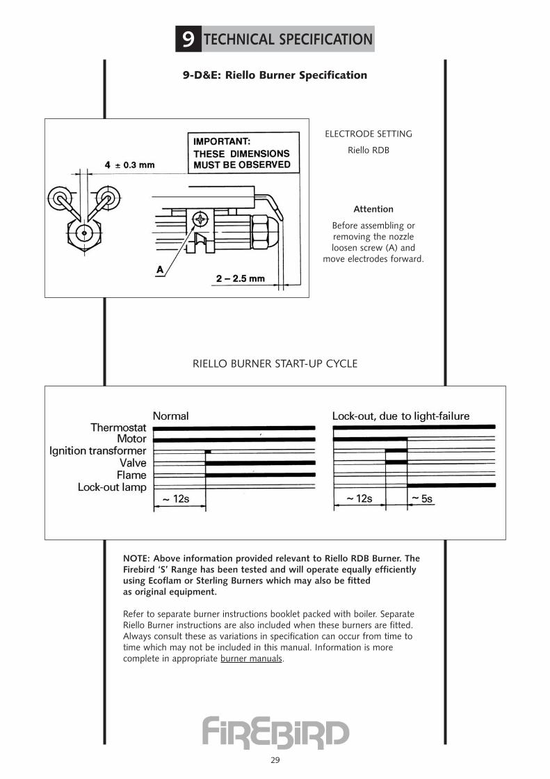
ELECTRODE SETTING
Riello RDB
RIELLO BURNER START-UP CYCLE
Attention
Before assembling orremoving the nozzleloosen screw (A) and
move electrodes forward.
NOTE: Above information provided relevant to Riello RDB Burner. TheFirebird ‘S’ Range has been tested and will operate equally efficientlyusing Ecoflam or Sterling Burners which may also be fittedas original equipment.
Refer to separate burner instructions booklet packed with boiler. SeparateRiello Burner instructions are also included when these burners are fitted.Always consult these as variations in specification can occur from time totime which may not be included in this manual. Information is morecomplete in appropriate burner manuals.
9 TECHNICAL SPECIFICATION
30
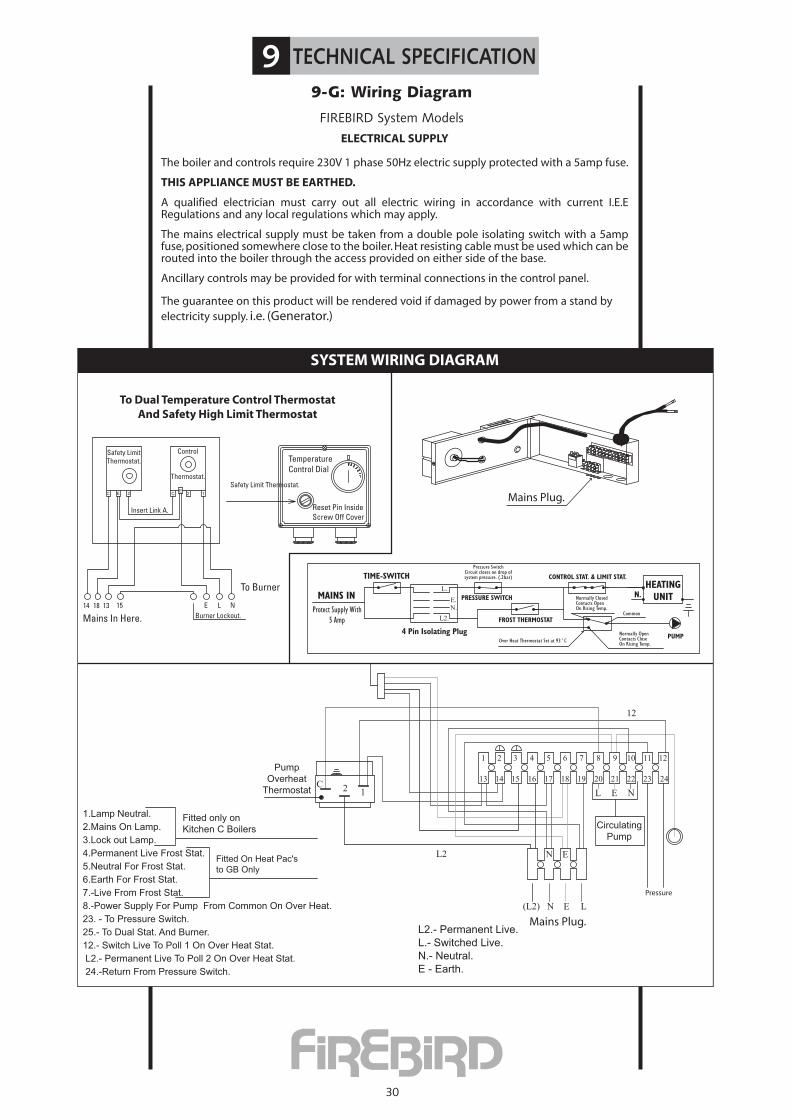
9-G: Wiring Diagram
FIREBIRD System ModelsELECTRICAL SUPPLY
The boiler and controls require 230V 1 phase 50Hz electric supply protected with a 5amp fuse.
THIS APPLIANCE MUST BE EARTHED.
A qualified electrician must carry out all electric wiring in accordance with current I.E.ERegulations and any local regulations which may apply.
The mains electrical supply must be taken from a double pole isolating switch with a 5ampfuse, positioned somewhere close to the boiler. Heat resisting cable must be used which can berouted into the boiler through the access provided on either side of the base.
Ancillary controls may be provided for with terminal connections in the control panel.
The guarantee on this product will be rendered void if damaged by power from a stand byelectricity supply. i.e. (Generator.)
7
19 20 21 22 23 2416 17 1813 14 15
121110
12C
12
Pressure
L2
1 4
L1
NEL
L
NL2
N(L2)
E
Mains Plug.E
C1 2
1 2 C E
2 E C
Safety LimitThermostat.
Control
Thermostat.
Insert Link A.
14 18 13 15 E NLBurner Lockout.
To Burner
Mains In Here.
Safety Limit Thermostat.
TemperatureControl Dial
Reset Pin InsideScrew Off Cover
To Dual Temperature Control ThermostatAnd Safety High Limit Thermostat
Firebird Kitchen C, System C & Heat Pac C' Wiring Diagram
Fitted only on
Kitchen C Boilers
1.Lamp Neutral.
2.Mains On Lamp.
3.Lock out Lamp.
4.Permanent Live Frost Stat.
5.Neutral For Frost Stat.
6.Earth For Frost Stat.
7.-Live From Frost Stat.
8.-Power Supply For Pump From Common On Over Heat.
23. - To Pressure Switch.
25.- To Dual Stat. And Burner.
12.- Switch Live To Poll 1 On Over Heat Stat.
L2.- Permanent Live To Poll 2 On Over Heat Stat.
24.-Return From Pressure Switch.
Fitted On Heat Pac's
to GB Only
L2.- Permanent Live.
L.- Switched Live.
N.- Neutral.
E - Earth.
Pump
Overheat
Thermostat
Circulating
Pump
E.N.
L.
L2.
N.
TIME-SWITCH
4 Pin Isolating PlugOver Heat Thermostat Set at 93˚C
Normally OpenContacts CloseOn Rising Temp.
PUMP
FROST THERMOSTAT
PRESSURE SWITCHMAINS INProtect Supply With
5 Amp
CONTROL STAT. & LIMIT STAT.HEATING
UNITNormally ClosedContacts OpenOn Rising Temp.
Common
Pressure SwitchCircuit closes on drop ofsystem pressure. (.2bar)
Mains Plug.
PUMP OVER HEAT THERMOSTATNOT IN KITCHEN MODELS
17 18 20 2114 1513 16 24232219
5 6 8 92 31 4 1211107
SYSTEM WIRING DIAGRAM

SystemOil Boiler
PART 2
System Filling
and Testing
31
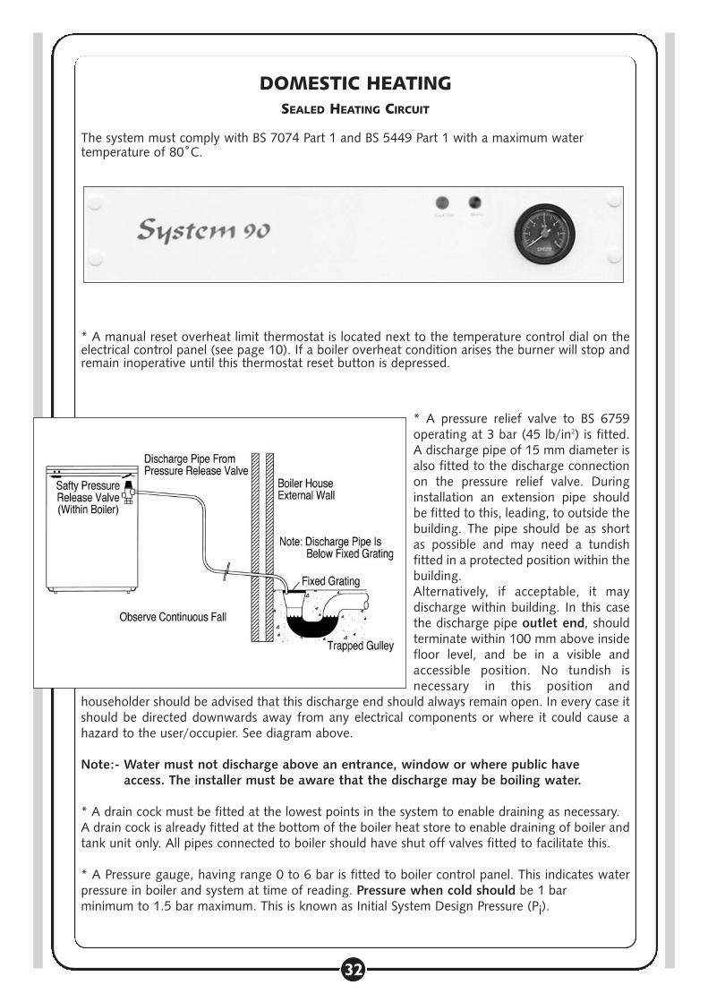
DOMESTIC HEATINGSEALED HEATING CIRCUIT
The system must comply with BS 7074 Part 1 and BS 5449 Part 1 with a maximum watertemperature of 80˚C.
* A manual reset overheat limit thermostat is located next to the temperature control dial on theelectrical control panel (see page 10). If a boiler overheat condition arises the burner will stop andremain inoperative until this thermostat reset button is depressed.
* A pressure relief valve to BS 6759operating at 3 bar (45 lb/in2) is fitted.A discharge pipe of 15 mm diameter isalso fitted to the discharge connectionon the pressure relief valve. Duringinstallation an extension pipe shouldbe fitted to this, leading, to outside thebuilding. The pipe should be as shortas possible and may need a tundishfitted in a protected position within thebuilding.Alternatively, if acceptable, it maydischarge within building. In this casethe discharge pipe outlet end, shouldterminate within 100 mm above insidefloor level, and be in a visible andaccessible position. No tundish isnecessary in this position and
householder should be advised that this discharge end should always remain open. In every case itshould be directed downwards away from any electrical components or where it could cause ahazard to the user/occupier. See diagram above.
Note:- Water must not discharge above an entrance, window or where public haveaccess. The installer must be aware that the discharge may be boiling water.
* A drain cock must be fitted at the lowest points in the system to enable draining as necessary.A drain cock is already fitted at the bottom of the boiler heat store to enable draining of boiler andtank unit only. All pipes connected to boiler should have shut off valves fitted to facilitate this.
* A Pressure gauge, having range 0 to 6 bar is fitted to boiler control panel. This indicates waterpressure in boiler and system at time of reading. Pressure when cold should be 1 barminimum to 1.5 bar maximum. This is known as Initial System Design Pressure (Pi).
32

A manually adjustable red pointer is also fitted on the protectiveglass of pressure gauge. This has a screwdriver slot. Whensystem is cold and filled to Initial Fill Pressure Pi this pointershould be rotated to read exactly as black pointer on dial.This should not be subsequently altered. If system pressure,as indicated on black pointer on dial, falls below that indi-cated by red pointer when system and boiler are cold thismeans that Initial System Fill Pressure has dropped. Refillsystem until indicated pressure rises to the same as redpointer indicates - in this case 0.7 bar, as shown onaccompanying pressure gauge sketch. Sketch also showsblack pointer indicating maximum final system designpressure (Pf).
N.B. Initial System Design Pressure (measured in bar) equals static head of system (measured in bar) plus 0.3.
* A 12 or 14 litre expansion vessel is fitted to boiler, precharged with air or nitrogen to 1 bar whichallows a system static head of 5 metres. If the static head is greater than this then the air chargein the vessel must be increased to balance the higher static head. The air charge should notexceed a pressure of 1.5 bar.
The Firebird Boiler with a built in Expansion Vessel’s having an initial air charge pressure of 1 bar.If total water content of system is greater than the capibilities of the vessel supplied then anadditional vessel will be required to be fitted to the return pipe as close as is practicable to theboiler. There should be no valves or restrictions between vessel and boiler.See page 34 for vessel sizes.
If static head is altered then it is also necessary to alter air charge pressure to equal static head(+ 0.3 Bar). This is necessary in order to keep system water from entering expansion vessel untilsystem is being heated and thus allow its maximum acceptance volume (V) to be used only toaccommodate the expansion of system water during boiler operation.
Remember that air charge pressure must be equal in both vessels (attached to the samesystem). In the above example this is 1 bar. Air charge pressure is the air pressure in expansionvessel before system is filled. It is measured with a tyre gauge attached to Schrader valve on thevessel.
N.B. N.B. With heating system up to full working temperature, if the final systemdesign pressure (Pf) reads more than 2.6 bar, as indicated on controlpanel pressure gauge, then it is likely that:
(a) Total system water content is greater than that calculated and ifadditional expansion vessel has been fitted it should be replacedwith a larger unitOR if integral boiler expansion vessel only is used then anadditional expansion vessel is required.
(b) Static head may be higher than calculated. In this case it isnecessary to re-measure static head and revise expansion vesselair charge pressure.
(C) Expansion vessel incorrect size or air charge pressure incorrect.
Refer to BS 7074 Part 1 and BS 5449 for further information.
33
B
A

DOMESTIC HEATING
EXPANSION VESSEL AND SYSTEM REQUIREMENTS
Safety Valve Setting 3 bar
Initial System Pressure 0.5 bar 1.0 bar 1.5 bar
Total Water Content of System TOTAL VESSEL VOLUME **
Litres Litres Litres Litres
25 2.1 2.7 3.9
50 4.2 5.4 7.8
75 6.3 8.2 11.7
100 8.3 10.9 15.6
125 10.4 13.6 19.5
150 12.5 ->[16.3]<- 23.4
175 14.7 19.1 27.2
200 16.7 21.8 31.2
225 18.7 24.5 35.1
250 20.8 27.2 39.0
FOR FURTHER INFORMATION CONSULT APPROPRIATE TRAINING MANUALSAND BS 7074 PART 1, BS 5449, ETC
* * When calculating size of any additional expansion vessel required, remember to deductthe boiler expansion vessel volume of 10 litres from the calculated
total system vessel volume required, as given in above table.
EXAMPLE: using above table
If ............................Total water content of system - 150 litresAnd ....................Initial system pressure required is - 1.0 barThen ..................Vessel volume required [from above table] - 16.3 litresBut ......................Vessel supplied with boiler - 10.0 litresTherefore ....Additional vessel required - 6.3 litres (minimum)
(For this system of 150 litres - total water volume)
..Nearest available stock size for additional vessel required, at 1 bar initial system pressure(taken from above table) is 8 Litres.
It is emphasised that the installer should be fully acquainted with sealed system installation andoperation, calculation of total system water volume, determining of initial system pressurerequired and calculation of any additional expansion vessel volume required.
NB .. Ensue that all expansion vessels in the same system are set at EQUAL air charge pressures.
34
� �
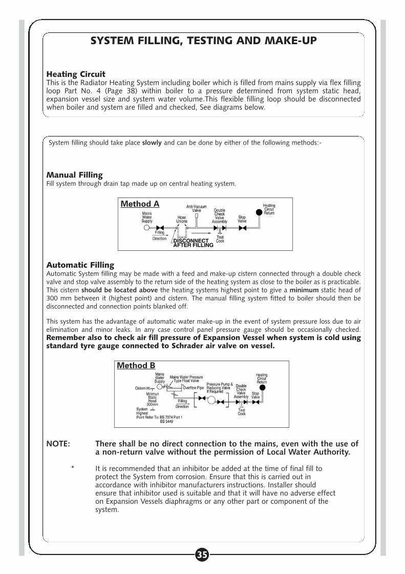
SYSTEM FILLING, TESTING AND MAKE-UP
Heating CircuitThis is the Radiator Heating System including boiler which is filled from mains supply via flex fillingloop Part No. 4 (Page 38) within boiler to a pressure determined from system static head,expansion vessel size and system water volume.This flexible filling loop should be disconnectedwhen boiler and system are filled and checked, See diagrams below.
35
System filling should take place slowly and can be done by either of the following methods:-
Manual FillingFill system through drain tap made up on central heating system.
Automatic FillingAutomatic System filling may be made with a feed and make-up cistern connected through a double checkvalve and stop valve assembly to the return side of the heating system as close to the boiler as is practicable.This cistern should be located above the heating systems highest point to give a minimum static head of300 mm between it (highest point) and cistern. The manual filling system fitted to boiler should then bedisconnected and connection points blanked off.
This system has the advantage of automatic water make-up in the event of system pressure loss due to airelimination and minor leaks. In any case control panel pressure gauge should be occasionally checked.Remember also to check air fill pressure of Expansion Vessel when system is cold usingstandard tyre gauge connected to Schrader air valve on vessel.
NOTE: There shall be no direct connection to the mains, even with the use ofa non-return valve without the permission of Local Water Authority.
* It is recommended that an inhibitor be added at the time of final fill toprotect the System from corrosion. Ensure that this is carried out inaccordance with inhibitor manufacturers instructions. Installer shouldensure that inhibitor used is suitable and that it will have no adverse effecton Expansion Vessels diaphragms or any other part or component of thesystem.
Method A
Method B

SYSTEM FILLING, TESTING AND COMMISSIONING
* Before proceeding to filling, ensure that electricity supply is switched off at mainsto avoid any possibility of time switch operating and passing power to applianceprior to filling.
Filling and Testing
Check that all connections, especially compression joints, are fully tightened. Re-check andensure that pressure vessel air charge is correct, then fill system with water via filling systemused. Turn off water supply before system pressure reaches safety valve operation point of3 bar. (Say 2 to 2.5 bar). Vent system via all manual air vents including circulating pumps,boiler, radiators, system high points. etc. Check that dust caps are loosened on auto air vents,keep constant check on system pressure gauge (fitted to control panel). If pressure has droppedreadmit water to above pressure. Ensure all appropriate boiler and system valves are open.
With water supply turned off, thoroughly flush out boiler and system to remove all foreignmatter before allowing boiler and pumps to operate. If in doubt drain system and repeat aboveprocedure. At this stage flushing-out water should be clean and clear of all foreignmatter.
Refill the system and again vent at all points as described above. Examine the complete systemfor water leaks having pressurised it to 1.5 - 2.5 bar. Correct any leaks, then check operation ofsafety valve by admitting further water until this valve operates. This should occur when systempressure rises to between 2.7 and 3.3 bar. When satisfied with valve operation, and with mainswater still turned off, draw off sufficient water until initial system design fill pressure (Pi). (coldfill) is established (0.5 - 1.5 bar - as calculated for system). The red pointer Bon pressure gauge should then be set at this initial system design pressure(Pi), i.e. system static head +0.3
Remember that initial cold fill pressure can only be checked whensystem water has properly cooled down. Check that finaloperating pressure (Pf) is under 2.5 bar with all radiators turnedon and up to highest working temperature. Should systemoperating pressure exceed this, check:
1. That initial cold fill pressure is correct and , if additionalexpansion vessel is fitted, that pressure is equal in each vessel,
2. That expansion vessels are sized correctly.
Special attention should be given to existing heating systems where a Firebird boilerhas replaced an existing unit. Extra effort should be made to ensure that all original pipework and radiators are repeatedly flushed. If possible use a proprietary cleansing agentsuitable for system as loosened scale and foreign matter canseriously reduce domestichot water performance and pump efficiency.
Use corrosion inhibitor of suitable type.
36
B
A
37
SystemOil Boiler
PART 3
Spare Parts

38
10 SPARE PARTS-BURNER
10-A Burner Parts IllustrationRiello RDB Burner
Riello RDB Burner PartsNo. Code Spare Parts Description
1 3008512 Gasket2 3006384 Flange3 3002433 Cup-Shaped Head3 3002447 Cup-Shaped Head4 3007513 Electrode Assembly5 3006552 Electrode Bracket6 3008642 Nozzle Holder7 3008878 Kit Seals8 3008643 Collar9 3008794 High Voltage Lead
10 3005708 Fan10 3008645 Fan11 3008647 Air Damper Assembly11 3008839 Air Damper Assembly12 3008646 P.E. Cell13 3008863 Lead14 3007479 Capacitor 4uf15 3007582 Needle Valve16 3008651 Regulator17 3000439 Pump Seal18 3008654 Pump19 3008653 Filter - O - Ring20 3007162 O - Ring21 3009068 Connector22 3007672 Flexible Oil Line23 3008644 Tube24 3008876 Pressure Gauge25 3000443 Joint26 3008650 Motor27 3008648 Coil28 3008879 Cover29 3008851 Lead Coil30 3008652 Control Box 535RSE/LD31 3008649 Projection

39
10 SPARE PARTS-BURNER
10-B Burner Parts IllustrationRiello Burner RDB 2.2 - (D)
17875003
••
••
AT
EK
SA
G2
4836003•
••
•E
GN
AL
F3
7052003•
AD
AE
H D
EP
AH
S - P
UC
37442003
•A
DA
EH
DE
PA
HS -
PU
C3
33 520 03•
•A
DA
EH
DE
PA
HS -
PU
C4
4978 003•
••
•A
DA
EL
EG
A TLO
V H
GIH
52556 003
••
••
TE
KC
AR
B E
DO
RT
CEL
E6
5588003•
••
•R
ED L
OH
ELZ
ZO
N7
54 880 03•
••
•C
RA
LL
OC
873 420 03
••
••
BY L
BM
ES
SA
RE
TLA
EH
98875 003
••
••
CN
AF01
7468003•
•C
YLB
ME
SS
A R
EP
MA
D RI
A01
9388003•
•C
YLB
ME
SS
A R
EP
MA
D RI
A11
64 680 03•
••
•A
LLE
C .E.P
2 1756 20 03
••
••
TE
KC
OS
ELO
P 4C
317382 003
••
••
Fµ
5,4
RO
TIC
AP
AC
B4 1
81 4700 3•
••
•G
ULP
NIP 4
5124 88003
••
••
RO
TC
EN
NO
C D
NA
EB
UT
6145 680 03
••
••
CP
MU
P7 1
344 00 03•
••
•A
TNI
OJ81
6382 003•
••
•C
RO
TIC
AP
AC
+ R
OT
OM
918 46 8003
••
••
BLI
OC
026588003
••
••
RO
TC
EN
NO
C12
946 8003•
••
•N
OIT
CE
TO
RP
2 2315 70 03
••
••
AYL
BM
ES
SA
ED
OR
TC
ELE
329788 003
••
••
RE
VO
C42
256 8003•
••
•B
XO
B LO
RT
NO
C52
1588003•
••
•LI
OC
DA
EL
62261 7003
••
••
AG
NIR-
O7 2
356 80 03•
••
•G
NIR-
O - R
ETL I
FA
822857 003
••
••
BE
VLA
V E
LD
EE
N92
156 8003•
••
•B
RO
TA
LU
GE
R03
9340003•
••
•A
LA
ES
PM
UP
13027 5003
••
••
AEL
B IX
ELF
2 3206 30 03
••
••
C4/1 - 8/3
RO
TC
EN
NO
C33
8609 003•
••
•C
8 /3 - 8 /3 R
OT
CE
NN
OC
43678 8003
••
••
CE
GU
AG
ER
US
SE
RP
538788003
••
••
SL
AE
S TI
K
NO I
TP I
RC
SE
D.
DO
C.
N
3515105351530535155053515506
ST
RA
P D
ESI
VD
A
**
sgni tti f
mum ini
m rof strap e rapS
=A
sgnitt if ytefa s cisab rof s tr ap erap
S =
B +
A sgnitt if ytefa s dedn
etxe ro f str ap erapS
=C
+ B
+ A
**
40
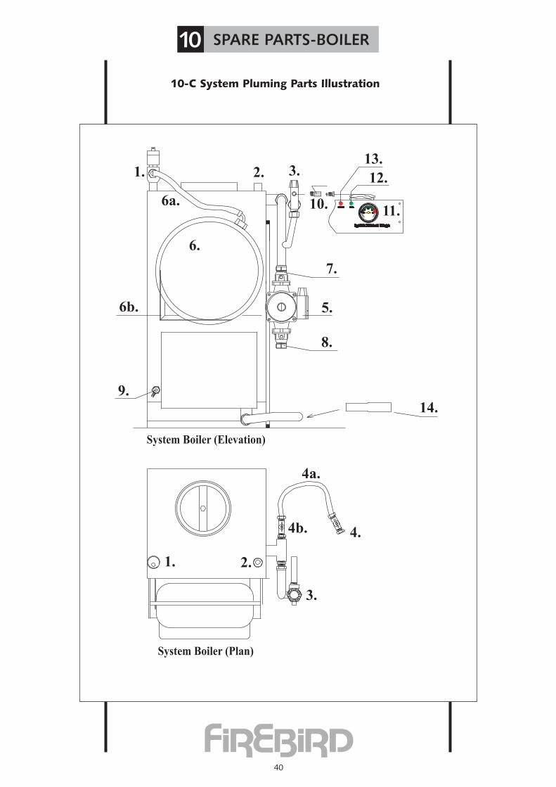
10-C System Pluming Parts Illustration
10 SPARE PARTS-BOILER
System Boiler (Elevation)
4b.
System Boiler (Plan)
4.
4a.
2.1.
3.
14.
9.
6b.
1.
6a.
6.
2. 3.
7.
5.
8.
10.
12.
13.
11.

41
10-D System Pluming Parts Description
10 SPARE PARTS-BOILER
ITEM COMPONENT 50-70 70-90 90-120 PART No.No.
1 Automatic air vent 1 1 1 FC 030102 Thermostat Pocket 1 1 1 FC 030202a Filler Spring 1 1 1 FC 03020a2b Locking Spring 1 1 1 FC 03020b3 Safety Valve 1 1 1 FC 030404 Filling loop isolating valve 1 1 1 FC 031004a Filling loop hose 1 1 14b Filling loop check valve 1 1 15 Circulating Pump 1 1 1 FC 031026 10 Ltr. Pressure Vessel 50/70 1 FC 0306070
12Ltr. Pressure Vessel 70/90 1 FC 030609014 Ltr. Pressure Vessel 90/120 1 FC 0306012
7 Pump Valve 22mm 2 2 1 FC 031018 Pump Valve 28mm 1 FC 03101289 1/2”drain cock 1 1 1 FC 0310310 1/4 M/Fm Check Valve 1 1 1 FC 03040CV11 Pressure Gauge 1 1 1 FC 0313411a Pressure Gauge Bracket 1 1 1 FC 0313511b Pressure Gauge Nut 1 1 1 FC0313612 Green Neon Light Indicator 1 1 1 FC0313813 Red Neon Light Indicator 1 1 1 FC 0314014 22mm to 28mm Copper 1 FC 032228
42
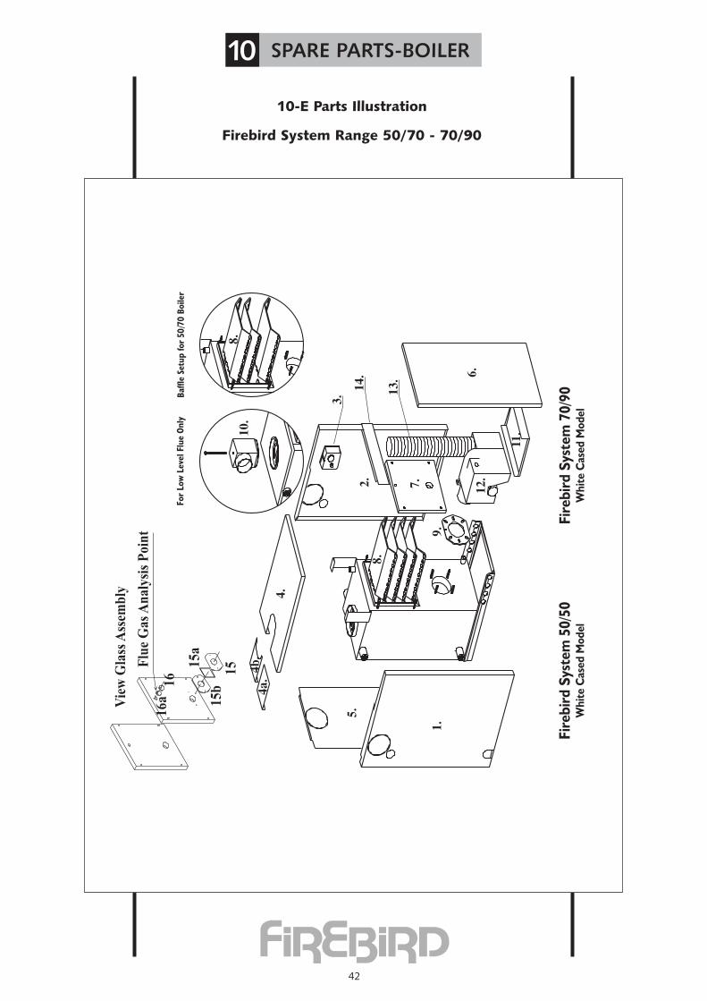
10-E Parts Illustration
Firebird System Range 50/70 - 70/90
10 SPARE PARTS-BOILER
Flu
e G
as
An
aly
sis
Po
int
Vie
w G
lass
Ass
emb
ly
15
a
15
b1
5
16
a1
6
Fire
bird
Sys
tem
50/
50W
hite
Cas
ed M
odel
Fire
bird
Sys
tem
70/
90W
hite
Cas
ed M
odel

10-F Parts Description
Firebird System Range 50/70 - 70/90
10 SPARE PARTS-BOILER
43
ITEM COMPONENT PART No. QtyNo. per boiler
1 Side Panel L H Side FC03118L 12 Side Panel R H Side FC03118R 13 Dual Stat IM TLSC 542764 14 Top Panel SS03121R 14a Flue Trim Plate FC03122 14b Conventional Trim Plate FC03123 16 Front Panel SS03120 17 Baffle Door - Door (3) FC0310890 18 Baffles (Gas Baffle) FS90 - R-09 49 Burner Mounting Flange R.D.B. 3006384 110 Flue Elbow FS90 - L-30 111 Drip Tray FS90 - L-31 112 Burner RDB 1 70190 (3513200) 113 Snorkel 3”snorkel pipe & jubilee clip 114 Instrument Panel SS70 - LS-L-46 115 Viewing glass bracket FC 03110 115a Viewing glass FC 03111 115b Viewing glass gasket P70-L-45 116 Flue gas analysis cover FC 03113 116a Flue gas analysis cover gasket FC 03114 1
1 Side Panel L H Side FC03118L 12 Side Panel R H Side FC03118R 13 Dual Stat IM TLSC 542764 14 Top Panel SS03121R 14a Flue Trim Plate FC03122 14b Conventional Trim Plate FC03123 16 Front Panel SS03120 17 Baffle Door - Door (3) FC0310890 18 Baffles (Gas Baffle) FS90 - R-09 49 Burner Mounting Flange R.D.B. 3006384 110 Flue Elbow FS90 - L-30 111 Drip Tray FS90 - L-31 112 Burner RDB 1 70190 (3513200) 113 Snorkel 3”snorkel pipe & jubilee clip 114 Instrument Panel SS70 - LS-L-46 115 Viewing glass bracket FC 03110 115a Viewing glass FC 03111 115b Viewing glass gasket P70-L-45 116 Flue gas analysis cover FC 03113 116a Flue gas analysis cover gasket FC 03114 1
Firebird System Range 50/70 White Cased Model
Firebird System Range 70/90 White Cased Model

44
10-G Parts Illustration
Firebird System Range 90/120 - 120/150 White Cased Model
10 SPARE PARTS-BOILER
Flu
e G
as
An
aly
sis
Poin
t
Vie
w G
lass
Ass
emb
ly
15a
15b
15
16a
16 Fi
rebi
rd S
yste
m 9
0/12
0W
hite
Cas
ed M
odel
Rem
ove
Seco
nd R
ow O
f Baf
fles
whe
nou
tput
is a
t low
er h
alf o
f ran
ge
Fire
bird
Sys
tem
120
/150
Whi
te C
ased
Mod
el

10-H Parts Description
Firebird System Range 90/120 - 120/150 White Cased Model
10 SPARE PARTS-BOILER
45
ITEM COMPONENT PART No. QtyNo. per boiler
1 Side Panel L H Side FC03118L 12 Side Panel R H Side FC03118R 13 Dual Stat IM TLSC 542764 14 Top Panel SS0312112 14a Flue Trim Plate FC03122 14b Conventional Trim Plate FC03123 15 Back Panel FS125 - BP-L-04 16 Front Panel SS0312012 17 Baffle Door FS125 - L-08 18 Baffles FS125 - L-09 89 Burner Mounting Flange See Burner Parts Book 110 Flue Elbow FS125 - L-30 111 Drip Tray FS125 - L-31 112 Burner RDB 2 (3513602) 113 Snorkel 3”snorkel pipe & jubilee clip 114 Instrument Panel FS125 - LS-L-46 115 Viewing glass bracket FC 03110 115a Viewing glass FC 03111 115b Viewing glass gasket P70-L-45 116 Flue gas analysis cover FC 03113 116a Flue gas analysis cover gasket FC 03114 1
1 Side Panel L H Side SS150 - LH-L-01 12 Side Panel R H Side SS150 - RH-L-02 13 Dual Stat IM TLSC 542764 14 Top Panel SS150 - TP-L-03 14a Flue Trim Plate SS150 - FTP-L-03 14b Conventional Trim Plate SS150 -CTGP-L-03 15 Back Panel SS150 - BP-L-04 16 Front Panel SS150 - FP-L-05 17 Baffle Door FS150 - L-08 18 Baffles FS150 - L-09 89 Burner Mounting Flange See Burner Parts Book 110 Flue Elbow FS150 - L-30 111 Drip Tray FS150 - L-31 112 Burner RDB 3 113 Snorkel 3”snorkel pipe & jubilee clip 114 Instrument Panel FS150 - LS-L-46 115 Viewing glass bracket FC 03110 115a Viewing glass FC 03111 115b Viewing glass gasket P70-L-45 1
Firebird System Range 90/120 White Cased Model
Firebird System Range 120/150 White Cased Model

46
10-I Parts Illustration
System Heat PAC 70
10 SPARE PARTS-BOILER
8.
13.7.11.
2.
6.
3.
1.
5.12.
17.
4.
9.
14.
16.15.
9a.
10.
Flue Gas Analysis Point
View Glass Assembly
18a
18b18
19a19
System Heat-Pac 70
10-I Parts Description
ITEM COMPONENT PART No. QtyNo. per boiler
1 Boiler HP70-L 12 Base HP70-L-101 13 Left side HP70-L-102 14 Right side HP70-L-102 15 Front HP70-L-103 16 Back HP70-L-104 17 Back flue outlet HP70-L-106 18 Top HP70-L-105 19 Boiler Door P70-L-08 19a Door Gasket P70-L-41 110 Baffles P90-L-09 311 Flue Kit HP70-L-14-3 112 Burner Riello G5X 113 Support Plate HP70-L-107 114 Thermostat IM TLSC542764 115 Frost stat. TLM 2257 116 Stat Mounting Bracket HP70-L-54 117 View glass18 Viewing glass bracket FC 03110 118a Viewing glass FC 03111 118b Viewing glass gasket P70-L-45 119 Flue gas analysis cover FC 03113 119a Flue gas analysis cover gasket FC 03114 1
47
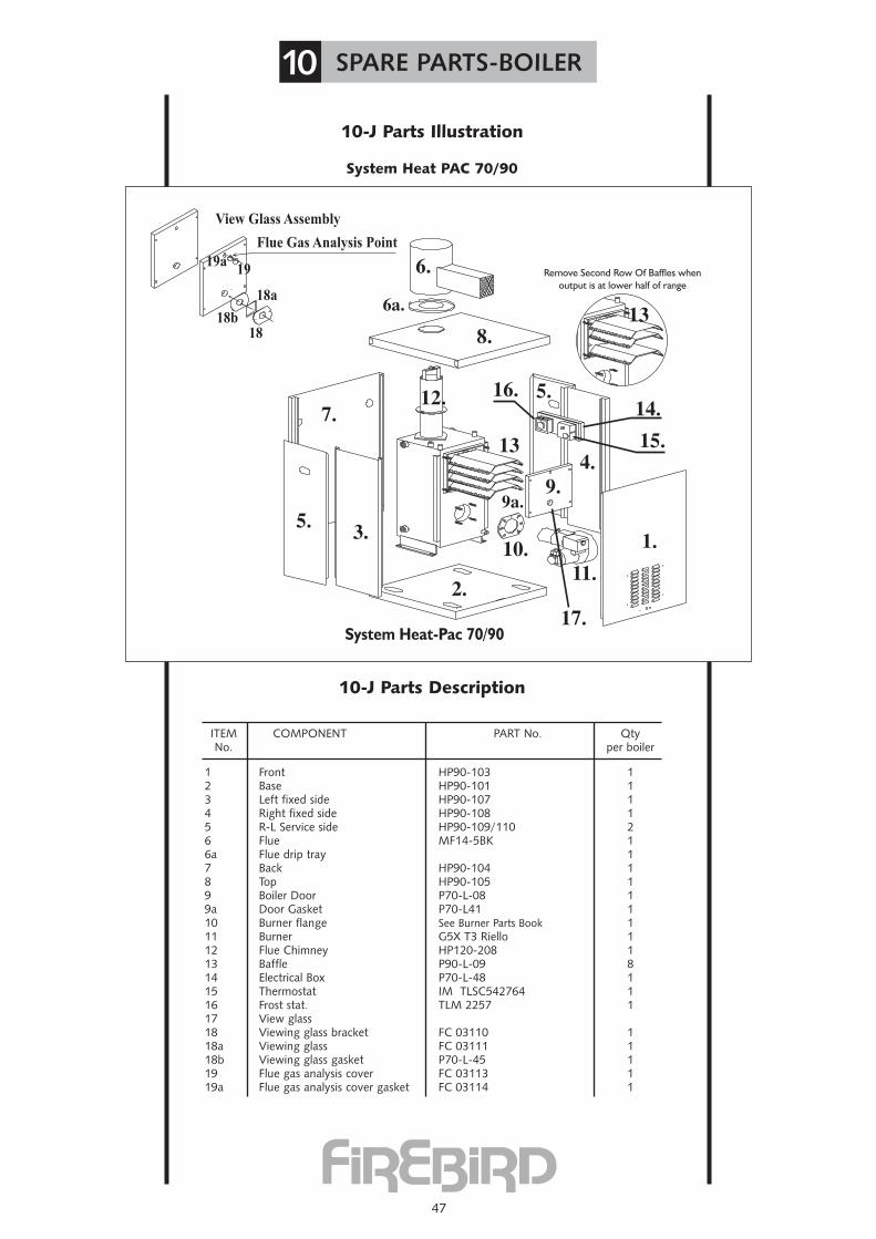
10-J Parts Illustration
System Heat PAC 70/90
10 SPARE PARTS-BOILER
Remove Second Row Of Baffles whenoutput is at lower half of range
System Heat-Pac 70/90
Flue Gas Analysis Point
View Glass Assembly
18a
18b18
19a19
10-J Parts Description
ITEM COMPONENT PART No. QtyNo. per boiler
1 Front HP90-103 12 Base HP90-101 13 Left fixed side HP90-107 14 Right fixed side HP90-108 15 R-L Service side HP90-109/110 26 Flue MF14-5BK 16a Flue drip tray 17 Back HP90-104 18 Top HP90-105 19 Boiler Door P70-L-08 19a Door Gasket P70-L41 110 Burner flange See Burner Parts Book 111 Burner G5X T3 Riello 112 Flue Chimney HP120-208 113 Baffle P90-L-09 814 Electrical Box P70-L-48 115 Thermostat IM TLSC542764 116 Frost stat. TLM 2257 117 View glass18 Viewing glass bracket FC 03110 118a Viewing glass FC 03111 118b Viewing glass gasket P70-L-45 119 Flue gas analysis cover FC 03113 119a Flue gas analysis cover gasket FC 03114 1
48
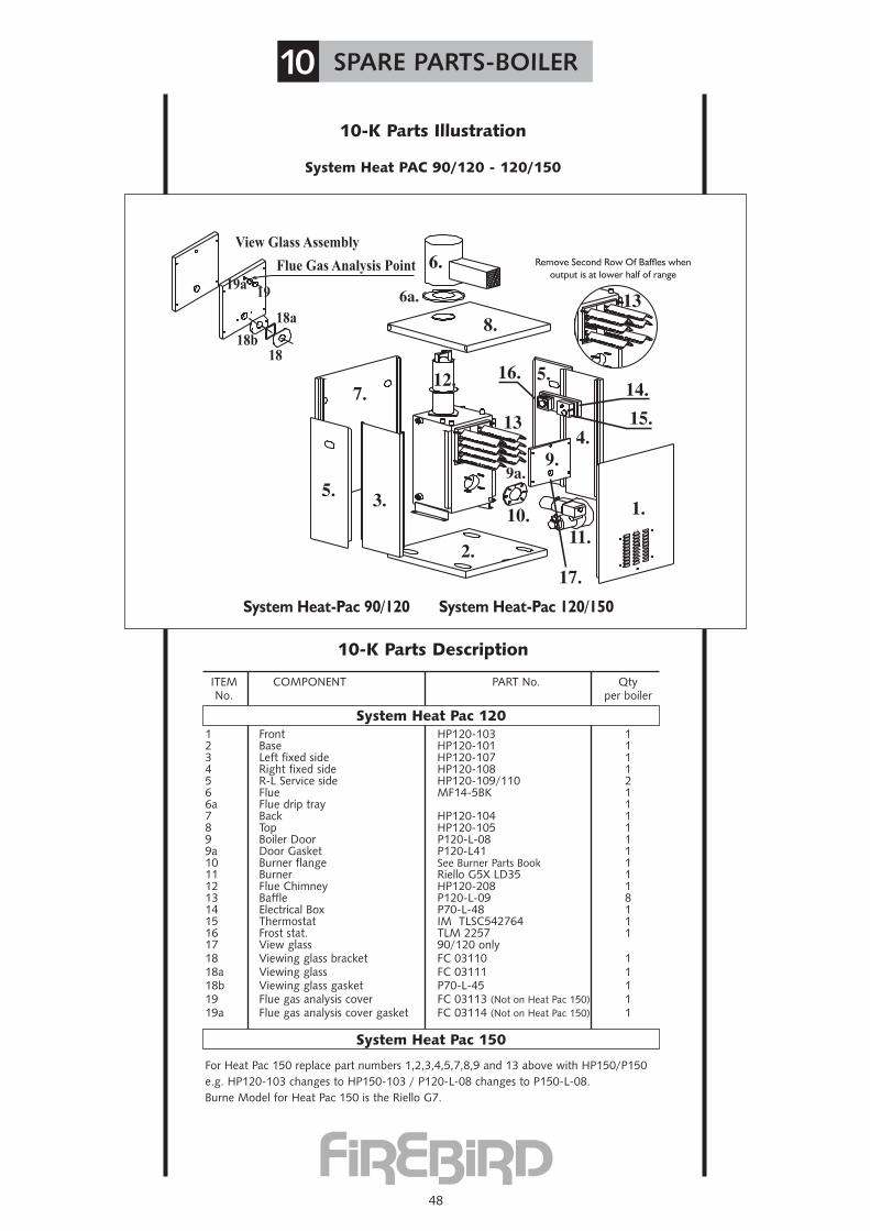
10-K Parts Illustration
System Heat PAC 90/120 - 120/150
10 SPARE PARTS-BOILER
Flue Gas Analysis Point
View Glass Assembly
18a
18b18
19a19
Remove Second Row Of Baffles whenoutput is at lower half of range
System Heat-Pac 90/120 System Heat-Pac 120/150
10-K Parts Description
ITEM COMPONENT PART No. QtyNo. per boiler
1 Front HP120-103 12 Base HP120-101 13 Left fixed side HP120-107 14 Right fixed side HP120-108 15 R-L Service side HP120-109/110 26 Flue MF14-5BK 16a Flue drip tray 17 Back HP120-104 18 Top HP120-105 19 Boiler Door P120-L-08 19a Door Gasket P120-L41 110 Burner flange See Burner Parts Book 111 Burner Riello G5X LD35 112 Flue Chimney HP120-208 113 Baffle P120-L-09 814 Electrical Box P70-L-48 115 Thermostat IM TLSC542764 116 Frost stat. TLM 2257 117 View glass 90/120 only18 Viewing glass bracket FC 03110 118a Viewing glass FC 03111 118b Viewing glass gasket P70-L-45 119 Flue gas analysis cover FC 03113 (Not on Heat Pac 150) 119a Flue gas analysis cover gasket FC 03114 (Not on Heat Pac 150) 1
For Heat Pac 150 replace part numbers 1,2,3,4,5,7,8,9 and 13 above with HP150/P150e.g. HP120-103 changes to HP150-103 / P120-L-08 changes to P150-L-08.Burne Model for Heat Pac 150 is the Riello G7.
System Heat Pac 120
System Heat Pac 150

Commissioning Record
49
This record should be carefully completed, remain in this manual and be left withhouseholder. A copy should be kept on file by engineer
NAME .................................................................................................................................................................................................................................................................................
ADDRESS .................................................................................................................................................................................................................................................................................
.................................................................................................................................................................................................................................................................................
POSTCODE .......................................................... TEL ..................................................................................................................................................................................................
BOILER MODEL ............................................................ OUTPUT ............................................................ SERIAL NUMBER ............................................................
INSTALLER/COMMISSIONING ENGINEER (In block capitals)
ADDRESS .......................................................................................................................
............................................................................................................................................
............................................................................................................................................
POSTCODE .................................... TEL .........................................................................
DATE ............................... NAME ..................................................................
COMMISSIONING COMPANY ....................................................................................
SIGNATURE .............................................................................................................
COMMISSIONING CHECK DETAILS
Burner Model � ...........................
Oil Type � ...........................
Nozzle Type � ...........................
Nozzle Size � ...........................
Nozzle Angle � ...........................
Pump Pressure � ...........................
Air � ...........................
Smoke Reading � ...........................
Flue Draft “W.g. � ...........................
CO2% � ...........................
F.G.T. ˚C � ...........................
Flue Seal � ...........................
Gaskets � ...........................
Fire Valve Location � ...........................
CHECK
Water � ...........................
All Connections � ...........................
Baffles � ...........................
Baffles in position and correct � ...........................
CHECK
D.M. Hot Water � ...........................
Central Heating � ...........................
Flow Switch � ...........................
Power Supply � ...........................
Notes: ......................................................................................................................................................................................................................
....................................................................................................................................................................................................................................
....................................................................................................................................................................................................................................
....................................................................................................................................................................................................................................
....................................................................................................................................................................................................................................

50
Service ReportNB All Information recorded hereunder should also be included in Engineers own filed service
reports. It is recommended that the boiler be serviced, at least once a year, and the details recorded below. Engineer should advise householder.
Burner Model � ...........................
Oil Type � ...........................
Nozzle Type � ...........................
Nozzle Size � ...........................
Nozzle Angle � ...........................
Pump Pressure � ...........................
Air � ...........................
Smoke Reading � ...........................
Flue Draft “W.g. � ...........................
CO2% � ...........................
F.G.T. ˚C � ...........................
Flue Seal � ...........................
Gaskets � ...........................
Fire Valve Location � ...........................
CHECK Water � ...........................
All Connections � ...........................
Baffles � ...........................
Baffles in position and correct � ...........................
CHECKD.M. Hot Water � ...........................
Central Heating � ...........................
Flow Switch � ...........................
Power Supply � ...........................
Date: ..................................
Service Engineer: ..................................
Tel. No: ..................................
Signature: ..................................
Comments: ..................................
..................................
..................................
..................................
� ...........................
� ...........................
� ...........................
� ...........................
� ...........................
� ...........................
� ...........................
� ...........................
� ...........................
� ...........................
� ...........................
� ...........................
� ...........................
� ...........................
� ...........................
� ...........................
� ...........................
� ...........................
� ...........................
� ...........................
� ...........................
� ...........................
..................................
..................................
..................................
..................................
..................................
..................................
..................................
..................................
� ...........................
� ...........................
� ...........................
� ...........................
� ...........................
� ...........................
� ...........................
� ...........................
� ...........................
� ...........................
� ...........................
� ...........................
� ...........................
� ...........................
� ...........................
� ...........................
� ...........................
� ...........................
� ...........................
� ...........................
� ...........................
� ...........................
..................................
..................................
..................................
..................................
..................................
..................................
..................................
..................................
� ...........................
� ...........................
� ...........................
� ...........................
� ...........................
� ...........................
� ...........................
� ...........................
� ...........................
� ...........................
� ...........................
� ...........................
� ...........................
� ...........................
� ...........................
� ...........................
� ...........................
� ...........................
� ...........................
� ...........................
� ...........................
� ...........................
..................................
..................................
..................................
..................................
..................................
..................................
..................................
..................................
1ST SERVICE 2ND SERVICE 3RD SERVICE 4TH SERVICE

51
Service ReportNB All Information recorded hereunder should also be included in Engineers own filed service
reports. It is recommended that the boiler be serviced, at least once a year, and the details recorded below. Engineer should advise householder.
Burner Model � ...........................
Oil Type � ...........................
Nozzle Type � ...........................
Nozzle Size � ...........................
Nozzle Angle � ...........................
Pump Pressure � ...........................
Air � ...........................
Smoke Reading � ...........................
Flue Draft “W.g. � ...........................
CO2% � ...........................
F.G.T. ˚C � ...........................
Flue Seal � ...........................
Gaskets � ...........................
Fire Valve Location � ...........................
CHECK Water � ...........................
All Connections � ...........................
Baffles � ...........................
Baffles in position and correct � ...........................
CHECKD.M. Hot Water � ...........................
Central Heating � ...........................
Flow Switch � ...........................
Power Supply � ...........................
Date: ..................................
Service Engineer: ..................................
Tel. No: ..................................
Signature: ..................................
Comments: ..................................
..................................
..................................
..................................
� ...........................
� ...........................
� ...........................
� ...........................
� ...........................
� ...........................
� ...........................
� ...........................
� ...........................
� ...........................
� ...........................
� ...........................
� ...........................
� ...........................
� ...........................
� ...........................
� ...........................
� ...........................
� ...........................
� ...........................
� ...........................
� ...........................
..................................
..................................
..................................
..................................
..................................
..................................
..................................
..................................
� ...........................
� ...........................
� ...........................
� ...........................
� ...........................
� ...........................
� ...........................
� ...........................
� ...........................
� ...........................
� ...........................
� ...........................
� ...........................
� ...........................
� ...........................
� ...........................
� ...........................
� ...........................
� ...........................
� ...........................
� ...........................
� ...........................
..................................
..................................
..................................
..................................
..................................
..................................
..................................
..................................
� ...........................
� ...........................
� ...........................
� ...........................
� ...........................
� ...........................
� ...........................
� ...........................
� ...........................
� ...........................
� ...........................
� ...........................
� ...........................
� ...........................
� ...........................
� ...........................
� ...........................
� ...........................
� ...........................
� ...........................
� ...........................
� ...........................
..................................
..................................
..................................
..................................
..................................
..................................
..................................
..................................
5TH SERVICE 6TH SERVICE 7TH SERVICE 8TH SERVICE

NOTES
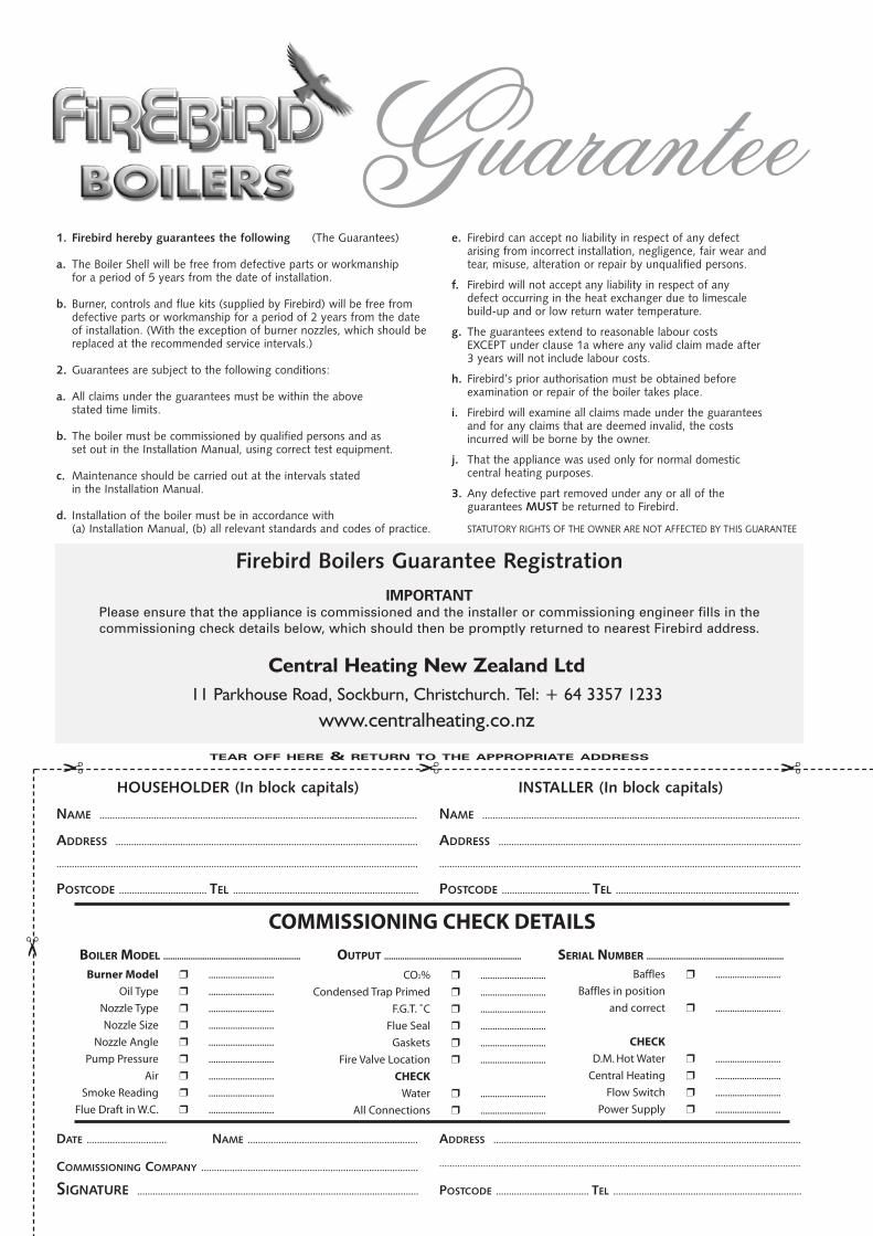
1. Firebird hereby guarantees the following (The Guarantees)
a. The Boiler Shell will be free from defective parts or workmanshipfor a period of 5 years from the date of installation.
b. Burner, controls and flue kits (supplied by Firebird) will be free fromdefective parts or workmanship for a period of 2 years from the dateof installation. (With the exception of burner nozzles, which should bereplaced at the recommended service intervals.)
2. Guarantees are subject to the following conditions:
a. All claims under the guarantees must be within the abovestated time limits.
b. The boiler must be commissioned by qualified persons and asset out in the Installation Manual, using correct test equipment.
c. Maintenance should be carried out at the intervals statedin the Installation Manual.
d. Installation of the boiler must be in accordance with(a) Installation Manual, (b) all relevant standards and codes of practice.
e. Firebird can accept no liability in respect of any defectarising from incorrect installation, negligence, fair wear andtear, misuse, alteration or repair by unqualified persons.
f. Firebird will not accept any liability in respect of anydefect occurring in the heat exchanger due to limescalebuild-up and or low return water temperature.
g. The guarantees extend to reasonable labour costsEXCEPT under clause 1a where any valid claim made after3 years will not include labour costs.
h. Firebird’s prior authorisation must be obtained beforeexamination or repair of the boiler takes place.
i. Firebird will examine all claims made under the guaranteesand for any claims that are deemed invalid, the costsincurred will be borne by the owner.
j. That the appliance was used only for normal domesticcentral heating purposes.
3. Any defective part removed under any or all of theguarantees MUST be returned to Firebird.
STATUTORY RIGHTS OF THE OWNER ARE NOT AFFECTED BY THIS GUARANTEE
TEAR OFF HERE & RETURN TO THE APPROPRIATE ADDRESS
Central Heating New Zealand Ltd 11 Parkhouse Road, Sockburn, Christchurch. Tel: + 64 3357 1233
www.centralheating.co.nz
IMPORTANTPlease ensure that the appliance is commissioned and the installer or commissioning engineer fills in thecommissioning check details below, which should then be promptly returned to nearest Firebird address.
Firebird Boilers Guarantee Registration
NAME ...........................................................................................................................
ADDRESS .....................................................................................................................
............................................................................................................................................
POSTCODE .................................. TEL ........................................................................
NAME ...........................................................................................................................
ADDRESS .....................................................................................................................
............................................................................................................................................
POSTCODE .................................. TEL .......................................................................
HOUSEHOLDER (In block capitals) INSTALLER (In block capitals)
ADDRESS .......................................................................................................................
............................................................................................................................................
POSTCODE .................................... TEL .........................................................................
DATE ............................... NAME ..................................................................
COMMISSIONING COMPANY ....................................................................................
SIGNATURE .............................................................................................................
���
�
BOILER MODEL ............................................................ OUTPUT ............................................................ SERIAL NUMBER ............................................................
COMMISSIONING CHECK DETAILS
Burner Model � ...........................
Oil Type � ...........................
Nozzle Type � ...........................
Nozzle Size � ...........................
Nozzle Angle � ...........................
Pump Pressure � ...........................
Air � ...........................
Smoke Reading � ...........................
Flue Draft in W.C. � ...........................
Baffles � ...........................
Baffles in position
and correct � ...........................
CHECK
D.M. Hot Water � ...........................
Central Heating � ...........................
Flow Switch � ...........................
Power Supply � ...........................
CO2% � ...........................
Condensed Trap Primed � ...........................
F.G.T. ˚C � ...........................
Flue Seal � ...........................
Gaskets � ...........................
Fire Valve Location � ...........................
CHECK
Water � ...........................
All Connections � ...........................
uaranteeG
................................................................................................................................................................................
................................................................................................................................................................................
................................................................................................................................................................................
................................................................................................................................................................................
................................................................................................................................................................................
AffixStampHere
For further information on Firebird Products please contact
© Copyright applies to all FIREBIRD products. Our policy is one of continual development and we therefore reservethe right to change without prior notice the specification of our products at any time and be without obligation to
make similar changes in products previously produced.
New Zealand Distributor
Central Heating New Zealand Ltd
11 Parkhouse Road,
Sockburn,
Christchurch,
+ 64 3357 1233
www.centralheating.co.nz
Central Heating New Zealand Ltd
52 Pilkington Way,
Wigram,
Christchurch.
PO Box 31-274
Top Related