


Languages
Pages
Legal


1 | P a g e
OFFICE OF MATERIALS AND TESTING
Testing Management Branch
Laboratory Soil Testing Technician
2021 Study Guide
2 | P a g e
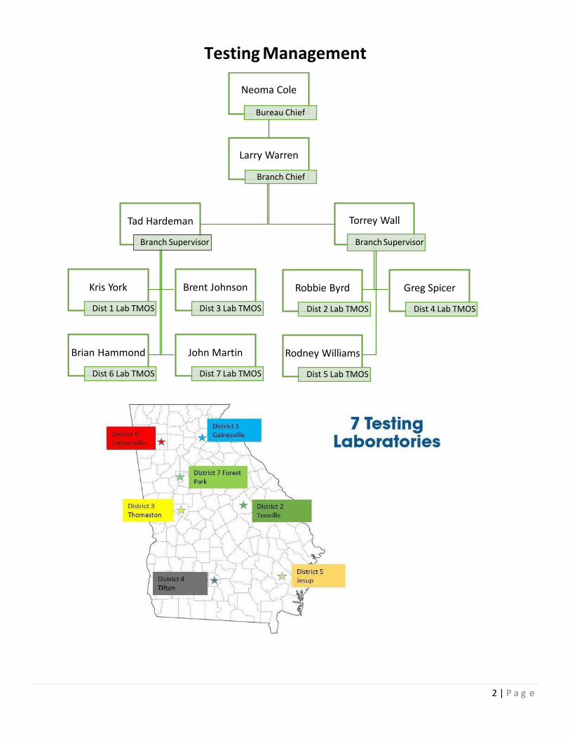
Testing Management
Neoma Cole
Bureau Chief
Larry Warren
Branch Chief
Tad Hardeman
Branch Supervisor
Kris York
Dist 1 Lab TMOS
Brent Johnson
Dist 3 Lab TMOS
Brian Hammond
Dist 6 Lab TMOS
John Martin
Dist 7 Lab TMOS
Torrey Wall
Branch Supervisor
Robbie Byrd
Dist 2 Lab TMOS
Greg Spicer
Dist 4 Lab TMOS
Rodney Williams
Dist 5 Lab TMOS

3 | P a g e
Table of Content
Laboratory Soil Testing Technician Certification Study Guide
Page Titles
4 Introduction 5-8 Program Information
9 Technical Sections
AASHTO Standards (Test Procedure Not Included)
10-13 R 58-11(2019) 14-18 T 89-13(2017) 19-22 T 90-20 23-25 T265-15(2019)
GDT Standards & Specifications 26-34 GDT 4 35-57 GDT 6 58-91
92-104 GDT 7 GDT 49
105-109 Specification Section 810 110-115 Specification Section 814
116-132 Appendix A Answers to Study Questions
4 | P a g e
INTRODUCTION
I. PURPOSE
The purpose of this study guide is to provide information that is required to learn the necessary procedures and standards
established by the Department to become qualified in Preparing and Testing Soils. The Sampling and Testing procedures
and Standards Specifications were established to ensure that high quality materials, that meet Specifications, are incor-
porated into the work. The evidence of testing is an “approved” test report.
The purpose and necessity for evidence of tests completed should be understood by all Contractors, Engineers and Tech-
nicians of the Department. It should not be thought that the purpose and only result of testing are test reports. However,
this evidence of testing is needed and important, for it is the record of performed tasks. A test report must give complete,
clear and precise results.
It is the Contractor’s responsibility to control the materials and construction in such a manner that the specifications are
met. It is the Materials Testing Technician and Engineer’s responsibility to evaluate materials and construction to verify
that Specifications are met.
All information included within this guide will aid in the success of Laboratory Testing Technicians becoming proficient
performing the essential tasks for Preparing, and Testing Soils used in roadway construction.

5 | P a g e
GEORGIA DEPARTMENT OF TRANSPORTATION
SOIL TESTING TECHNICIAN CERTIFICATION
CERTIFICATION PROGRAM
Definition:
A Soil Level 1 Testing Technician— is an individual who has demonstrated the knowledge and ability to properly per-
form, record, and report the results of basic laboratory procedures for soils.
Scope and Knowledge:
The program requires a working knowledge of the following:
AASHTO/ASTM standards:
▪ R 58-11(2019)—Standard Practice for Dry Preparation of Disturbed Soil and Soil-Aggregate Samples for Test
▪ T 89-13(2017)—Standard Method of Test for Determining the Liquid Limit of Soils
▪ T 90-20— Standard Method of Test for Determining the Plastic Limit and Plasticity Index of Soils
▪ T265-15(2019)—Standard Method of Test for Laboratory Determination of Moisture Content of Soils
❖ Note: Due to copyright laws, AASHTO Test Procedures are not provided. AASHTO Procedures may be obtained at
https://compass.astm.org
External Companies (Non-GDOT) must provide their employees their own copy of AASHTO Standards due to the copyright laws
GDOT Standards/Specifications:
▪ GDT 4—Determining Gradation of Soils
▪ GDT 6—Determining Volume Change of Soils
▪ GDT 7—Determining Maximum Density of Soils
▪ GDT 49--Determining the Theoretical Maximum of Dry Density of Materials containing > 25% retained on the no.
10 sieve using a 10-pound rammer and an 18-inch drop
▪ Section 810—Roadway Materials
▪ Section 814—Soil Base Materials
Certification Requirements:
GDOT will grant certification only to those applicants who meet both of the following requirements:
1. A passing grade on the GDOT written examination, and
2. Successful completion of the GDOT performance examination

6 | P a g e
Written Examination
The written examination is three hours, open-book, and consists of 100 multiple-choice
questions. To pass the written examination, both of the following conditions must be met:
1. At least 60% correct for each of the required standards, and
2. A minimum score of 75% overall.
The Technical College System of Georgia will administer the written examination. Examinees will be expected to pay a
testing fee when the written portion of the examination is administered.
The campus locations where the written examinations will be administered are as follows.

7 | P a g e
College Name Number Email
Albany Matt Trice 229-430-6618 [email protected]
Athens John Usry 706-357-0050 [email protected]
Atlanta Araceli Flores 404-225-4681 [email protected]
Augusta Laura Giddings 706-771-5705 [email protected]
Central Ga Melanie Bradley 478-2183289 [email protected]
Chattahoochee Tammy Huffstetler 770-528-4041 [email protected]
Coastal Pines Anna McCrea 912-287-5854 [email protected]
Columbus Michelle Shaw 706-649-1558 [email protected]
GA Northwestern Patty Hart 706-272-2980 [email protected]
GA Piedmont Angela Cooper 404-297-9522, ext.1829
Gwinnett Gwen Moran 678-226-6609 [email protected]
Lanier Joan Lee 770-5336995 [email protected]
North GA Leslie Foster 706-754-7715 [email protected]
Oconee Fall Line Katrina Veal 478-275-6592 [email protected]
Ogeechee Kristen Waters 912-871-1693 [email protected]
Savannah Lisa Kuyk 912-443-4148 [email protected]
South GA Tami Blount 912-931-2040 [email protected]
Southeastern Susan Rustin 912-538-3197 [email protected]
Southern Crescent Steve Hendrix 678-972-9443 [email protected]
Southern Regional (Moultrie campus)
Jena Willis 229-217-4257 [email protected]
Southern Regional (Bain- bridge campus)
Susanne Reynolds 229-243-3011 [email protected]
Southern Regional (Thom- asville campus)
Ruby Barron 229-227-2579 [email protected]
West GA NO TESTING n/a n/a
Wiregrass Christy Cobb 229-468-2218 [email protected]
8 | P a g e
Performance Examination
The performance examination will be administered by the Georgia Department of Transportation’s Office of Materials and
Testing staff at the Central Laboratory in Forest Park, Georgia, or at the Branch Laboratory associated with each of the
Department’s Field Districts.
The performance examination is closed-book and requires actual demonstration of the required standards. The examinee
is judged on his/her ability to correctly perform or describe all the required procedures for the 8 standards listed. No
performance examination is required for specifications Section. The performance examination must be passed within 90
days of passing the written examination.
During the examination the examinee will be judged on their ability to perform or describe all required procedures for
each of the AASHTO or GDOT standards based on the criteria in the Performance Examination Checklists. Omission or
incorrect performance on one or more of the prescribed procedures will constitute failure of that trial. The examinee will
be allowed up to (2) trials on the day of the examination for each GDOT/AASHTO Standard. If during one trial the examinee
feels an error has been made, he or she may suspend that trial and begin the procedure over. A voluntary suspension of a
trial is not counted as a failure. Failure on any of the prescribed standards after two trials will constitute failure of the
performance examination. The performance examination is graded on a pass/fail basis.
Re-Examination
Failure of either the written or performance examination by any of the criteria cited above will require the re-examination
on the entire written exam or entire performance exam. It is the examinee’s responsibility to request a re-examination.
To protect GDOT’s Soil Technician Examinations from frivolous trial-and-error attempts and to encourage the examinee
to properly prepare for testing, the following allowances are required.
▪ After first failed examination, the examinee must wait 30 days before re-testing.
▪ After second failed examination, the examinee must wait 90 days before re-testing.
▪ After third failed examination, the examinee must wait 12 months before re-testing.
Recertification
Technicians are not required to have any continuous education credit hours to maintain their Soils Testing Technician
Certification after they have successfully passed the written and practical exams and become certified.
Regardless of re-certification status, for the purpose of fulfilling the requirements of SOP 30 as required by the FHWA,
active technicians (those who performed acceptance testing in the last calendar year) are required to have an IA evaluation
during each calendar year.

9 | P a g e
GEORGIA DEPARTMENT OF TRANSPORTATION
SOIL TESTING TECHNICIAN CERTIFICATION
WORKBOOK TECHNICAL SECTIONS
Each section consists of:
• GDOT Specification/Standard or AASHTO Standard
• Study Questions
• Performance Checklist, if applicable

10 | P a g e
SECTION 1
AASHTO R 58-11(2019)
Standard Practice for Dry Preparation of
Disturbed Soil and Soil-Aggregate Samples for Test

11 | P a g e
STUDY QUESTIONS
AASHTO R 58, Standard Practice for Dry Preparation of
Disturbed Soil and Soil-Aggregate Samples for Test
1. This method describes the preparation of soil and soil–aggregate samples?
2. A revolving drum, into which the soil sample and rubber-covered rollers are placed, is a suitable pulverizing de-
vice?
a) True
b) False
3. For the particle size analysis-T88, material passing a 2.00-mm (No. 10) sieve is required in amounts equal to ap-
proximately, 110 g for soils and approximately 60 g for soils.
4. What is the minimum amount required, of material passing the 0.425-mm (No. 40) sieve, for performing physi-
cal testing?
5. Samples should be dried at a temperature not exceeding ?
6. Representative test samples of the amount required to perform the desired tests shall be taken with ,
or by and .
7. Samples dried in an oven or other drying apparatus at a temperature not exceeding 60°C [140°F] are considered
to be air dried?
a) True
b) False
8. List the two alternate methods used to separate fraction sizes of the portion of the dried sample selected for
particle-sized analysis and physical tests?
9. Fractions retained on the 4.75-mm (No. 4) sieve and the 2.00-mm (No. 10) sieve are not included in the sieve
analysis and should be discarded?
a) True
b) False
10. What is the required sample mass of material passing the 2.00-mm (No. 10) sieve, for specific gravity, when the
volumetric flask is to be used?
11. Physical tests are performed on materials passing the sieve?
12 | P a g e
PERFORMANCE CHECKLIST
AASHTO R 58, Standard Practice for Dry Preparation of
Disturbed Soil and Soil-Aggregate Samples for Test
Procedure
1. Dry the soil sample thoroughly in air or in the drying apparatus at a temperature not exceeding 60°C [140°F].
2. Obtain a test sample of the required mass to perform the desired tests (Section 4), with a sampler, or by splitting
or quartering.
3. Pulverize the samples in such a way as to avoid reducing the natural size of individual particles.
4. Determine the mass of the portion of the dried sample selected for particle-sized analysis and physical tests (in-
cluding specific gravity).
5. Record mass as the mass of total sample uncorrected for hygroscopic moisture.
6. Separate into fractions by one of the following methods:
Alternate Methods Using 2.00-mm (No. 10) Sieve
7. Separate the dried sample into two fractions using a 2.00-mm (No. 10)sieve.
8. Pulverize the material retained on the sieve until the aggregations of soil particles are broken into separate
grains.
9. Re-sieve the ground soil on the 2.00-mm (No. 10) sieve.
Alternate Method Using 4.75-mm and 2.00-mm (Nos. 4 and 10) Sieves
10. Separate the dried sample into two fractions using a 4.75-mm (No. 4)sieve.
11. Pulverize the material retained on the sieve until the aggregations of soil particles are broken into separate
grains.
12. Re-sieve the ground soil on the 4.75-mm (No. 4) sieve.
13. Thoroughly mix the fractions passing the 4.75-mm (No. 4) sieve.
14. By use of a sampler, or split and quarter the sample, obtain a representative portion adequate for the desired
tests.
15. Separate the dried sample into two fractions using a 2.00-mm (No. 10) sieve.
16. Pulverize the material retained on the sieve until the aggregations of soil particles are broken into separate
grains.
17. Re-sieve the ground soil on the 2.00-mm (No. 10) sieve.
18. Record the mass of the material from this split-off fraction that is retained on the 2.00-mm (No. 10) sieve for
later use in coarse sieve analysis computations.
Procedure-continued

13 | P a g e
19. Set aside the fraction retained on the 2.00-mm (No. 10) sieve, or that retained on the 4.75-mm (No. 4) sieve,
after the second sieving, for use in sieve analysis of the coarse material.
20. Thoroughly mix the fractions passing the 2.00-mm (No. 10) sieve.
21. By use of a sampler, or split and quarter the sample, obtain representative portions having approximate masses
as follows: (1) for the hydrometer analysis and sieve analysis of the fraction passing the 2.00-mm sieve, 110 g for
sandy soil and 60 g for silty or clayey soils; and (2) for specific gravity, 25 g when the volumetric flask is to be used
and 10 g when the stoppered bottle is to be used.
22. Sieve the remaining portion of the material passing the 2.00-mm (No. 10) sieve over a 0.425-mm (No. 40) sieve.
23. Pulverize the fraction retained on the 0.425-mm (No. 40) sieve in such a manner as to break up the aggregations
without fracturing the individual grains.
24. Separate the ground soil into two fractions by means of the 0.425-mm (No. 40) sieve, and regrind the material
retained on the sieve.
25. Discard material retained on the 0.425-mm (No. 40) sieve when repeated grinding produces only a small quan-
tity of soil passing the 0.425-mm sieve.
26. Thoroughly mix the several fractions passing the 0.425-mm sieve obtained from the grinding and sieving opera-
tions and set aside for use in performing the physical tests.

14 | P a g e
SECTION 2
AASHTO T 89-13(2017)
Standard Method of Test for
Determining the Liquid Limit of Soils

15 | P a g e
STUDY QUESTIONS
AASHTO T 89
Standard Method of Test for
Determining the Liquid Limit of Soils
1. The liquid limit of a soil is that at which the soil passes from a plastic to a liquid state.
2. An , dish about 115 mm in diameter is preferred for mixing the sample.
3. The liquid limit device shall have a base made of material.
4. List the two types of grooving tools used in this procedure.
5. The flat grooving tool should be used interchangeably with the curved grooving tool?
a) True
b) False
6. Obtain a sample mass of about g of material passing -mm sieve for method “A”.
7. Cup or base wear is considered excessive when the point of contact exceeds in diameter.
8. The height of drop of the cup should be adjust to and checked prior to testing.
9. What is the initial amount of water to be added to the sample?
a) Method “A”:
b) Method “B”:
10. It is ok to add dry soil material if too much moisture has been added to the sample.
a) True
b) False
11. A value may be obtained by adding water too fast.
12. What is the maximum thickness allowed when spreading material into the testing cup?
13. How many firm strokes of the grooving tool are allowed to divide the soil in the cup?
14. The cup containing the sample shall be and by turning crank F at a rate of
approximately revolutions per second.
15. What steps are taken should the sample slide on the cups surface during test?
16. The and shall be washed and dried between test trials.
17. When performing procedure “A”, obtain the first test sample in the range of to shocks.

16 | P a g e
18. Water content of the soil shall be calculated as follows:
a) True
b) False
𝑚𝑎𝑠𝑠 𝑜𝑓 𝑤𝑎𝑡𝑒𝑟
𝑚𝑎𝑠𝑠𝑜𝑓𝑜𝑣𝑒𝑛 𝑑𝑟𝑖𝑒𝑑 𝑠𝑜𝑖𝑙 𝑋 100
19. The moisture content corresponding to the intersection of the flow curve with the -shock ordinate
shall be taken as the of the soil.
20. Sample shall be seasoned in the for when performing referee testing.
17 | P a g e
PERFORMANCE CHECKLIST
AASHTO T 89
Standard Method of Test for
Determining the Liquid Limit of Soils
METHOD A
Procedure
1. Thoroughly mix the portion of material passing the 0.425-mm sieve and obtain a sample with a mass of about 100
g.
2. Thoroughly mix sample with 15 to 20 mL of distilled water by alternately and repeatedly stirring, kneading, and
chopping with a spatula.
3. Continue mixing and add further additions of water, in increments of 1 to 3 mL, until the material forms a uniform
mass of stiff consistency. Thoroughly mix each increment of water, as previously described in step No. 2, before
another increment of water is added.
4. Place a sufficient quantity of material in the cup and squeeze and spread, using as few strokes as possible.
5. Level with spatula and, at the same time, trim to a depth of 10 mm at the point of maximum thickness.
Curved Grooving Tool
6. Divide the soil in the cup with a firm stroke of the grooving tool. Up to six strokes, from front to back or back to
front, may be used and only the last stroke should scrape the bottom of the cup.
Alternate Procedure (Flat Grooving Tool)
7. Form a groove in the soil pat in accordance with Section 11.2 of ASTM D4318.
Procedure-Continued
8. Lift and drop the cup, at a rate of approximately two revolutions per second, until the two sides of the sample
come in contact at the bottom of the groove along a distance of about 13 mm.
9. Record the number of shocks required to close the groove.
10. Remove a slice of soil the width of the spatula, extending from edge to edge of the soil cake at right angles to the
groove and including that portion of the groove that flowed together, and place in a suitable container.
11. Dry the sample in accordance with T 265and determine the moisture content.
12. Transfer the soil remaining in the cup to the mixing dish and wash the cup and grooving tool.
13. Repeat procedure, adding sufficient water to bring the sample to a more fluid condition.
14. Obtain the first sample in the range of 25 to 35 shocks, the second sample in the range of 20 to 30 shocks, and
the third sample in the range of 15 to 25 shocks. The range of the three determinations shall be at least 10 shocks.

18 | P a g e
15. Plot a “flow curve”, on a semilogarithmic graph, representing the relation between moisture content and corre-
sponding number of shocks. The moisture content corresponding to the intersection of the flow curve with the
25-shock ordinate shall be taken as the liquid limit of the soil.
METHOD B
Procedure
16. Thoroughly mix the portion of material passing the 0.425-mm sieve and obtain a sample with a mass of about 50
g.
17. Using the curved grooving tool or the flat grooving tool the procedure shall be the same as prescribed in steps 2
through 12 except that the initial amount of water to be added shall be approximately 8 to 10 mL.
18. Obtain the first sample in the range of 22 to 28 shocks, and immediately return the soil remaining to the mixing
dish, without adding additional water, and repeat the test. If the second closure occurs in the acceptable range of
22 to 28 shocks and the second closure is within 2 shocks of the first closure, secure a moisture content specimen.

19 | P a g e
SECTION 3
AASHTO T 90-20
Standard Method of Test for
Determining the Plastic Limit and Plasticity Index of Soils
20 | P a g e
STUDY QUESTIONS
AASHTO T 90
Standard Method of Test for
Determining the Plastic Limit and Plasticity Index of Soils
1. The of a soil is the lowest at which the soil remains plastic.
2. The plasticity index is the numerical difference between the and the of the soil.
3. What method shall be used as the referee method?
4. Wax paper would be an acceptable rolling surface?
a) True
b) False
5. The container used for moisture content shall have a to prevent the loss of moisture from the
samples before initial mass determination.
6. If only the plastic limit is determined, what is the initial sample mass, of material passing the 0.425-mm (No. 40)
sieve, required for this procedure?
7. Tap water may be used for routine testing?
a) True
b) False
8. The soil mass should be rolled into a at a rate of per minute.
9. What is the time limit for rolling the soil mass into a thread?
10. When using the alternate procedure, you should not allow the soil thread to contact the of the
plastic limit device?
11. It is acceptable for crumbling to occur when the diameter is than 3 mm, provided the solid has
been previously rolled into a thread in diameter?
12. Attempts should be made to produce failure at exactly 3-mm by reducing hand pressure?
a) True
b) False
13. soils require much pressure to deform the thread as they approach the plastic limit?
14. What procedure should be used to determine the moisture content?
15. The plastic limit of the soil is the moisture content expressed as a percentage of the ?
16. Report the plastic limit to the nearest ?
17. How is the plasticity index of a soil calculated? – =Plastic Index

21 | P a g e
PERFORMANCE CHECKLIST
AASHTO T 90
Standard Method of Test for
Determining the Plastic Limit and Plasticity Index of Soils
If Only Plastic Limit is Determined
1. Take a quantity of soil with a mass of about 20 g from the thoroughly mixed portion of the material passing the
0.425-mm (No. 40) sieve.
2. Place test sample in a mixing dish and thoroughly mix with distilled, demineralized, or de-ionized water until the
mass becomes plastic enough to be shaped into a ball.
3. Take about 10 g from this ball for the test sample.
If the Plasticity Index (Both Liquid and Plastic Limit) is to be Determined
4. Take a test sample with a mass about 10 g from the thoroughly wet and mixed portion of the soil prepared in
accordance with T 89. Take sample at any stage in the mixing process when the mass can be easily shaped into a
ball without sticking to fingers.
5. Set aside and allow to season in air until the liquid limit test has been completed.
Procedure
6. Determine and record the mass of the moisture container.
7. Take a 1.5 to 2.0-g portion from the 10-g mass ball of soil.
8. Roll the soil mass into a 3-mm-diameter thread using at a rate of 80 to 90 strokes per minute, counting a stroke
as moving the hand forward and back to the starting position.
Hand Rolling Method
9. Roll mass between the palm or fingers and the unglazed paper or glass plate to a uniform diameter throughout
its length.
10. Continue to deform the thread until its diameter reaches 3 mm.
11. Take no more than 2 minutes to roll the test sample to a 3-mm-diameter.
Procedure Continued
12. When the diameter of the thread reaches 3 mm, form the mass back into an ellipsoidal shape using the thumbs
and fingers.
13. Repeat hand rolling operation until the soil can no longer be rolled into a thread and begins to crumble.

22 | P a g e
14. Gather and place the portions of crumbled soil in moisture content container and cover with a close-fitting lid to
prevent moisture loss.
15. Repeat hand rolling operation until the entire 10 g sample is tested.
16. Place all crumbled portions of soil in the same moisture content container.
17. Determine moisture content in accordance with T 265.

23 | P a g e
SECTION 4
AASHTO T 265-15(2019)
Standard Method of Test for
Laboratory Determination of Moisture Content of Soils
24 | P a g e
STUDY QUESTIONS
AASHTO T 265
Standard Method of Test for
Laboratory Determination of Moisture Content of Soils
1. or of a soil is the ratio, expressed as a percentage, of the mass of water in a given
mass of soil to the mass of the solid particles?
2. Containers shall have close-fitting lids to prevent from samples before initial weighing and to
prevent from the atmosphere following drying and before final weighing.
3. If not indicated in the method of test, what is the minimum sample mass for a soil with a maximum particle size
of 12.5-mm (1/2 in.)?
4. Test samples shall be dried in a drying oven maintained at a temperature of ?
5. Samples should be dried overnight (minimum of hr) or dry until the mass loss of the sample after 1 h of
additional drying is less than percent (constant mass)?
6. Dried samples should be removed before placing wet samples in the oven?
a) True
b) False
7. Oven-drying at 110 ± 5°C (230 ± 9°F) does not result in reliable moisture content values for soil containing
or other minerals having loosely bound water from or for soil containing significant
amounts of .
8. When is it acceptable to use a container without a tight-fitting lid?
9. When calculating moisture content, W₁ = ?
10. What is the single operator precision, acceptable range of two results, when testing a coarse aggregate-blend?

25 | P a g e
PERFORMANCE CHECKLIST
AASHTO T 265
Standard Method of Test for
Laboratory Determination of Moisture Content of Soils
1. Select a representative quantity of moist soil in the amount indicated in the method of test. If no amount is indi-
cated, the minimum mass of the sample shall be in accordance with the table in T 265.
2. Weigh a clean, dry container with its lid and place the moisture content sample in the container.
3. Immediately place lid on container and weigh the container, including the sample and lid.
4. Remove the lid and place the container with the moist sample in the drying oven.
5. Dry the sample dry overnight (15 h minimum) at a temperature of 110 ± 5°C (230 ± 9°F) or until the mass loss of
the sample after 1 h of additional drying is less than 0.1 percent (constant mass).
6. Remove the sample from the oven and immediately place lid on the container.
7. Allow sample to cool to room temperature.
8. Weigh container, including the sample and lid.
9. Calculate the moisture content to the nearest 0.1 percent.

26 | P a g e
SECTION 5
GDT 4
Determining Gradation of Soils

27 | P a g e
GDT 4
A. Scope
For a complete list of GDTs, refer to the STI (Sampling, Testing and Inspection) section of “The Source”, which is the
Georgia Department of Transportation’s online reference for contractors.
Use this test method to quantitatively determine particle size in soils, soil aggregate, graded aggregate, and similar roadway
materials.
B. Apparatus
The apparatus consists of the following:
1. Oven: A thermostatically controlled drying oven capable of maintaining temperatures of 230 ± 9 °F (110 ± 5 °C) for
drying the sieve analysis samples.
2. Balance: The balance shall have sufficient capacity, be readable to 0.1 percent of the sample mass, or better, and con-
form to the requirement of AASHTO M 231.
3. Sieves: A series of sieves consisting of the #40, #60 and #200, constructed with a square mesh woven cloth, conforming
to the requirements of ASTM E11. 4. Mechanical Sieve Shaker—A mechanical sieving device, if used, shall create motion of the sieves to cause the particles
to bounce, tumble, or otherwise turn so as to present different orientations to the sieving surface. The sieving action
shall be such that the criterion for adequacy of sieving described in Section D, Step No. 23, is met in a reasonable time
period.
5. Large Pan: Suitable large pan made of material resistance to corrosion and subject to change in mass or disintegration
from repeated use or other suitable device such as a large cloth.
6. Scoop: Suitable device for mixing and sampling the material.
7. Sample Splitter—A suitable riffle sampler or sample splitter for proportional splitting of the sample and capable of ob-
taining representative portions of the sample without appreciable loss of fines. The width of the container used to feed
the riffle sample splitter should be equal to the total combined width of the riffle chutes. Proportional splitting of the
sample on a canvas cloth is also permitted. Note—The procedure for proportional splitting is described in R 76.
8. Storage Cups: Use pint-sized (0.473 L) cups or other suitable containers identified numerically for storing a sample of
the material. 9. Funnel: Use a funnel with at least a 3 in (75 mm) intake diameter and at least a 1/2 in outlet diameter to put soil into
bottles without spilling.
10. Bottles: a or b
a. Use 8 oz (237 ml), wide-mouth bottles, approximately 1.3 in (33 mm) inside mouth diameter, 5.35 in (136 mm) high, and 4 in (102 mm) from the bottom to the bottom of the neck. This bottle requires a siphoning wand that has a
reach of 3.5 in (89 mm) from the top of the bottle with a clearance from the bottom of the wand to the bottom of the bottle of 1.625 in ± 1/16 in (41.3 mm ± 1.6 mm).The bottles must be clear and free from chips.
b. Use 8 oz (237 ml), wide-mouth bottles, approximately 1.2 in (30 mm) inside mouth diameter, 5.5 in (140 mm)
high, and 4 in ( 102 mm) from the bottom to the bottom of the neck. This bottle requires a siphoning wand that has
a reach of 3.7 in (94 mm) from the top of the bottle with a clearance from the bottom of the wand to bottom of the
bottle 1.625 in ± 1/16 in (41.3 mm ± 1.6 mm). The bottles must be clear and free from chips.
11. Sodium Hexametaphosphate Solution: Use a mixture of 5 gal (19 L) potable water, and 10 oz (285 g) of Sodium Hex-
ametaphosphate.
12. Timing Device: A watch or clock readable to the nearest second.
13. Evaporation Dishes: Use dishes to evaporate the water from the minus No. 10 (2.00 mm) sample.
14. Water Changing Assembly: Use a reversible-fill siphon assembly for changing the water in the bottle. The device shall
consist of 1/4 in (6 mm) copper or stainless steel tubing of such length that when placed into the bottle, the end reaches 1.625 in ± 1/16 in (41.3 mm ± 1.6 mm) from bottom of the bottle. The water supply should have an aspirator for the
fill/empty cycle.
15. Bottle Flushing Assembly: Use a 3/16 in (4 to 6 mm) copper tube bent into an ogee shape and preferably mounted sta-
tionary on a working platform at eye level. The outlet end of the tube should be pointed up, and the middle of the tube should be oriented such that an evaporating dish will fit under it.
Optional: The copper or stainless steel tube may be hand-held provided all the material is washed into the dish and the
dish does not overflow.
16. Bottle: Use a 5 gal (19 L) aspirator bottle.

28 | P a g e
17. Stirring Device: Any nonporous device suitable for stirring the sample mixture without loss of material.
C. Sample Size and Preparation
1. Prepare the sample received from the field in accordance with AASHTO R 58, Standard Practice for Dry Preparation of
Disturbed Soil and Soil-Aggregate Samples for Test.
2. Separate the materials retained on the No. 10 (2.00 mm) sieve into a series of sizes 3 in., 2 in., 1 in., 3/8in., and the No.
4 (75, 50, 25, 9.5 and 4.75-mm) sieves and using other sieves as may be needed depending on the sample or on the
specification for the material being testing.
3. Weigh and record the cumulative weights retained, for the coarse (plus No. 10) materials, in accordance with AASHTO
T-27, Standard Method of Test for Sieve Analysis of Fine and Coarse Aggregate.
4. Transfer the portion of material passing the No. 10 (2.00 mm) sieve, obtained from the portion of the sample selected
for particle analysis in step No. 1, into a large pan or onto a suitable cloth and mix it thoroughly.
5. Using a sampler, or by splitting or quartering, obtain representative portions, from the thoroughly mixed materials pre- pared in step No. 4, having the following masses: (1) for GDT 6 – volume change of soils, 1000 +/- 1g; (2) for GDT 7 –
maximum dry density and optimum moisture, 3000g; and (3) for grading the minus No. 10 (2.00 mm) material by elu- triation, a pint-sized storage cup.
D. Procedures
Grading the Minus No. 10 (2.00 mm) Material by elutriation.
Grade the minus No. 10 (2.00 mm) material by elutriation when the governing Standard Specifications call for GDT-4. The
process is:
1. Using a sampler, or by splitting or quartering, obtain two 50g samples from the material in the pint-sized storage cup.
2. Place one sample in an evaporating dish.
3. Dry the sample to a constant mass at a temperature of 230 ± 9 °F (110 ± 5 °C).
4. Weigh the sample and determine its mass to the nearest 0.1g. Record this mass as Sample No. 1. Use this value as the
original dry weight to calculate the grading of the minus No. 10 (2.00 mm) material.
5. Fill a test bottle to approximately 2 in. (50mm) of sodium hexametaphosphate solution.
6. Use the funnel to place the second sample into the test bottle containing hexametaphosphate solution.
7. Bump the funnel a few times to ensure that the fines clinging to the surface fall into the test bottle.
8. Vigorously stir the soil with a suitable nonporous stirring device(e.g.) to reduce the cohesive forces of the clay.
9. Allow the test bottle, containing sodium hexametaphosphate solution and soil, to stand for a minimum of 10 minutes.
10. Using the water change assembly, add water to the test bottle in a manner that will vigorously agitate the material. Con-
tinue to add water, using the agitating action, until the test bottle is filled to the height where the bottleneck begins.
11. Allow the test bottle, water, and sample to stand undisturbed for 8 to 10 minutes.
12. Using the water change assembly, siphon off the fluid level to about 3/4 in. (18mm) above the soil.
13. Using the water change assembly, refill the test bottle in a manner that will vigorously agitate the material. Continue to
add water, using the agitating action, until the test bottle is filled to the height where the bottleneck begins.
14. Allow the test bottle, water, and sample to stand undisturbed for 8 to 10 minutes.
15. Repeat steps No. 10 through No. 14 until the fluid above the sample becomes clear enough, after step No. 14, to read a
watch on the opposite side of the test bottle.
16. Using the water change assembly, siphon off the water and transfer the soil and remaining water from the test bottle into
an evaporating dish.
17. Flush the inside of the test bottle clean with two or three short spurts of water from the bottle flushing assembly into the
evaporating dish. Be careful not to lose any portion of the sample.
18. Allow the sample to stand in the evaporating dish until the liquid clears.
19. Decant excess water with care not to lose any of the fine material.
20. Dry the material to constant mass at a temperature of 230 ± 9°F (110 ± 5°C).
21. Weigh the sample and determine its mass to the nearest 0.1g. Record this mass as Sample No. 2.

29 | P a g e
22. Sieve the dry sample over a nest of sieves, the No. 40, No. 60, and No. 200, arranged in order of decreasing size from
top to bottom.
23. Continue sieving for a sufficient period and in such manner that, after completion, not more than 0.5 percent by mass of
the sample No. 2, as determined in step No. 21, passes any sieve during 1 min of continuous hand sieving performed as
follows: Hold the individual sieve, provided with a snug-fitting pan and cover, in a slightly inclined position in one
hand. Strike the side of the sieve sharply and with an upward motion against the heel of the other hand at the rate of
about 150 times per minute, turn the sieve about one sixth of a revolution at intervals of about 25 strokes.
24. Determine the mass of each size increment to the nearest 0.1g.
25. The total mass of the material after sieving shouldn’t differ by more than 0.3 percent of the total original dry mass of the sample placed on the sieves, sample No. 2. If the two amounts differ by more than 0.3 percent, based on the total origi-
nal dry sample mass, the results should not be used for acceptance purposes.
26. Calculate percentages passing, total percentages retained, and clay percentage to the nearest 0.1 percent on the basis of
the total mass of Sample No. 1, determined in step No. 4. These test results shall be used to classify soils, as established
in GDOT Standard Specifications, Section 810-Materials, Table 1.
27. When required, compute the sieve analysis and clay percentage, of materials passing the No. 10 (2.00 mm) sieve, to
represent the total sample as determined in Section E., Step No. 2 and Step No. 4.
E. Calculations
1. Retained (percent) = 100 (B A)
Passing (percent) = 100 (A - B) A
Check: percent retained + percent passing = 100.0 percent
Where:
A = the total sample weight if the sieve is No. 10 (2.00 mm) or larger, or
A = the weight of the 50.0 g sample (Sample No. 1) after it was dried to a constant weight if the sieve is smaller
than the No. 10 (2.00 mm)
B = cumulative weight retained on the specific sieve
Adjust the gradation of the minus No. 10 (2.00 mm) portion to represent the total sample as follows:
C = D x E 100 where:
C = percent of the total sample smaller than the specific sieve
D = percent passing the No. 10 (2.00 mm) sieve
E = percent of the minus No. 10 (2.00 mm) portion that passed the specific sieve
Examples of Calculations:
Total Sample Weight = 28,650 g
Gradation of Plus No. 10 (2.00 mm)
Sieve Accumulative Weight Re- tained
Percent of Total Sample
Retained Passing
1-1/2 (37.5 mm) 0 0 100.0
3/4 (19.0 mm) 5,850 20.4 79.6
10 (2.0 mm) 17,450 60.9 39.1
Accumulative percent retained on and passing the 3/4 in (19.0 mm) sieve:
Retained on 3/4 in (19.0 mm) sieve = 100 (B A)
= 100 (5,850 28,650) = 100 (0.204)
= 20.4 percent retained
Passing 3/4 in (19.0 mm) sieve = 100 (A - B) A
= 100 (28,650 – 5,850) 28,650

30 | P a g e
= 100 (0.796) = 79.6 percent passing
Check: percent retained + percent passing = 100.0 percent
20.4 percent + 79.6 percent = 100.0 percent
Gradation of Minus No. 10 (2.00 mm)
Weight of 50 g sample after drying = 49.1 g Adjusted for Total Sample Percent Pass-
ing
Sieve Accumulative Weight Retained
Retained Passing
40 (425 µm) 19.5 39.7 60.3 23.6
60 (250 µm) 27.1 55.2 44.8 17.5
200 (75 µm) 40.0 81.5 18.5 7.2
Total 44.1 89.8
Clay (effluent) = 10.2 4.0
Retained on No. 60 (250 µm) = 100 (B A)
= 100 (27.1 49.1)
= 100 (0.552)
= 55.2 percent retained
Passing No. 60 (250 µm) = 100 (A - B) A
= 100 (49.1 - 27.1) 49.1
= 100 (22.0) 49.1 = 44.8 percent passing
Minus No. 60 (250 µm) in total sample = (D x E) 100
= (39.1 x 44.8) 100
= 1751.68 100
= 17.5 percent
Clay is the material washed from the 50 g sample; therefore, it is not in the washed sample.
Clay (percent) in minus No. 10 (2.00 mm)
= 100 (A - B) A
= 100 (49.1 - 44.1) 49.1 = 100 (0.102)
= 10.2 percent
4. Clay (percent) in total sample = (D x E) 100
= (39.1 x 10.2) 100
= 3.988 or 4.0 percent
F. Report
1. Report the percent passing each sieve to the nearest 0.1 percent.
2. Report the percent clay to the nearest 0.1 percent.
STUDY QUESTIONS
GDT 4
Determining Gradation of Soils
1. Glass bottles used for this procedure must be and free of ?
2. A Sodium Hexametaphosphate solution mixture of potable water, and
______________________of Sodium Hexametaphosphate is needed for this procedure?
3. A siphon assembly is used for changing the water in the bottle?
4. Initial drying of the sample shall be performed at a temperature not exceeding ?
5. If coarse material is present, what test procedure is used to grade the aggregates?
6. Samples for density, and volume change are taken from materials that pass the sieve?
Procedure
7. How many samples of material passing the No. 10 (2.00 mm) sieve are weighed out for grading and what
are their individual masses?
8. The sample used for determining the original dry weight, for calculating the grading of the minus No. 10
(2.00 mm) material, should be dried to a ?
9. How much sodium hexametaphosphate solution should be in the test bottle when initially adding the test
sample?
10. The sample in the test bottle should be with a to reduce the cohesive
forces of the clay.
11. How long should the test sample and hexametaphosphate solution be allowed to stand before adding wa-
ter?
12. After filling the test bottle with water, the test bottle should be allowed to stand for -
to minutes before the water is siphoned off?
13. Fluid should be siphoned off until itis about above the soil?
14. The refilling and siphoning process should continue until the fluid above the sample becomes clear enough
to read a on the of the bottle.
31 | P a g e

32 | P a g e
15. Washed samples should be dried to a constant mass at atemperature of ?
16. When calculating the percent passing a sieve smaller than the No. 10 (2.00 mm), A = the weight of the 50.0
g sample after it was dried to a constant weight?
a) True
b) False
17. Calculate percent passing and adjusted for total percent passing:
Total Sample Weight = 28, 000g
Gradation of Plus No. 10 (2.00 mm)
Sieve Accumulative Weight Retained
Percent of Total Sample
Retained Passing
1-1/2 (37.5 mm) 0 0 100.0
3/4 (19.0 mm) 5,000
10 (2.0 mm) 17,000
Gradation of Minus No. 10 (2.00 mm)
Weight of 50 g sample after drying = 49.5 g Adjusted for Total Sample Percent
Passing
Sieve Accumulative Weight Retained
Retained Passing
40 (425 µm) 16.3
60 (250 µm) 26.5
200 (75 µm) 39.8
Total 42.6
Clay (effluent) =
33 | P a g e
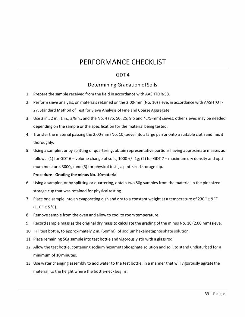
PERFORMANCE CHECKLIST
GDT 4
Determining Gradation of Soils
1. Prepare the sample received from the field in accordance with AASHTO R-58.
2. Perform sieve analysis, on materials retained on the 2.00-mm (No. 10) sieve, in accordance with AASHTO T-
27, Standard Method of Test for Sieve Analysis of Fine and Coarse Aggregate.
3. Use 3 in., 2 in., 1 in., 3/8in., and the No. 4 (75, 50, 25, 9.5 and 4.75-mm) sieves, other sieves may be needed
depending on the sample or the specification for the material being tested.
4. Transfer the material passing the 2.00-mm (No. 10) sieve into a large pan or onto a suitable cloth and mix it
thoroughly.
5. Using a sampler, or by splitting or quartering, obtain representative portions having approximate masses as
follows: (1) for GDT 6 – volume change of soils, 1000 +/- 1g; (2) for GDT 7 – maximum dry density and opti-
mum moisture, 3000g; and (3) for physical tests, a pint-sized storage cup.
Procedure - Grading the minus No. 10 material
6. Using a sampler, or by splitting or quartering, obtain two 50g samples from the material in the pint-sized
storage cup that was retained for physical testing.
7. Place one sample into an evaporating dish and dry to a constant weight at a temperature of 230 ° ± 9 °F
(110 ° ± 5 °C).
8. Remove sample from the oven and allow to cool to room temperature.
9. Record sample mass as the original dry mass to calculate the grading of the minus No. 10 (2.00 mm) sieve.
10. Fill test bottle, to approximately 2 in. (50mm), of sodium hexametaphosphate solution.
11. Place remaining 50g sample into test bottle and vigorously stir with a glass rod.
12. Allow the test bottle, containing sodium hexametaphosphate solution and soil, to stand undisturbed for a
minimum of 10 minutes.
13. Use water changing assembly to add water to the test bottle, in a manner that will vigorously agitate the
material, to the height where the bottle-neck begins.

34 | P a g e
14. Allow the test bottle, containing sodium hexametaphosphate solution, water, and soil, to stand undis-
turbed for a minimum for 8 to 10 minutes.
15. Use water changing assembly to siphon off the fluid to approximately 3/4 in (18 mm) above the sample.
16. Using the water change assembly, refill the test bottle in a manner that will vigorously agitate the material.
Continue to add water, using the agitating action, until the test bottle is filled to the height where the bot-
tle neck begins.
17. Repeat steps 13 through 16 until the fluid above the sample becomes clear enough, after step 16, to read a
watch on the opposite side of the bottle.
18. Transfer the test sample to an evaporating dish.
19. Dry the test sample to a constant mass at a temperature of 230 ° ± 9 °F (110 ° ± 5°C).
20. Remove test sample from oven and allow to cool to room temperature.
21. Sieve the dry sample over the No. 40, No. 60, and No. 200 sieves.
22. Report the percent passing each sieve, and the percent clay, to the nearest 0.1 percent.

35 | P a g e
SECTION 6
GDT 6
Determining Volume Change of Soil

36 | P a g e
GDT 6
A. Scope
This method describes the procedure used to determine the volume change of soil caused by the absorption and loss of water.
B. Apparatus
The apparatus consists of the following:
1. Swell Mold—A cylindrical metal mold approximately four 4 ± .02 in (100 ± 0.51 mm) inside diameter and 1 ± .01 in
(2.5 ± 0.13 mm) high. Each mold is fitted with a detachable perforated base plate and a removable extension approx-
imately 2 in (50.8 mm) high. (See Figure 1)(WM-08).
2. Shrinkage Mold—The same mold as the swell mold except it requires close tolerances. The height at any point is 1 ±
.005 in (25 + 0.13 mm) and diameter at any point is 4 ± .01 in (100 + 0.25mm). Paint the shrinkage mold a different
color to distinguish it from the swell molds(WM-08).
3. Rammer—A metal rammer having a 2 in (50mm) diameter flat circular face and weighing 5.5 lbs (2.49 kg). Has a
controlled height of free-fall of 12 1/8 in ± 0.06 (303 ± 1.5 mm) (WR-1). When using a mechanical rammer, observe
the following:
a. After use each day, oil the shaft with a thin lubricant.
b. Before use each day, wipe clean the shaft and allow to drop 25 times to standardize the shaft friction.
c. Check the mechanical rammer for tolerances semi-annually using the procedures in AASHTO T-99.
4. Water Vat—A pan at least 1½ in (38 mm) deep with a bottom flat enough that the water surface strikes the same
point within 1/16 in (1.6 mm) on all mold assemblies in the vat. Place a screen wire or similar object in the vat to
ensure that water can get under the molds.
5. Drying Rack—A flat perforated metal plate with five 3/8 in (10 mm) diameter holes located symmetrically under
each specimen used to dry and cool shrinkage specimen.
6. Absorbent Papers—Absorbent paper used in the swell test. Two types of absorbent paper are used: a Number 1
qualitative 4 in (l00 mm) diameter paper placed in the bottom of the mold, and a double thickness paper towel
measuring about 4½ in (114 mm) square is wet and placed on top of the specimen after the water level has been
adjusted (WP-03-1).
7. Extruder—A cylindrical device 3.90 TO 3.97 in (99.1 to 100.8 mm) diameter used to remove the
compacted shrinkage specimen from the mold(WS-9).
8. Scales—A balance or scale having a capacity in excess of 2.2 lbs (1000 g), sensitive to 0.0022 lbs (1.0 g).
(WB-ELC-1).
9. Drying Oven—An oven with the temperature thermostatically controlled to 230 ° ± 9 °F (110 ° ± 5 °C) used to dry
the shrinkage specimen.
10. Knife—A stiff sharp blade approximately 12 in (300 mm) long with the cutting edge straight to within 1/32 in (0.8
mm) throughout its length. Used for slicing the compacted specimen flush with the top of the mold-(WS-13-1).
11. Swell Thickness Measuring Device—Device consisting of a one 1 in (25.4 mm) travel micrometer dial readable to
and sensitive to one-thousandth 0.001 in (0.025 mm) and the stand shown in Figure 2. Measure the original and final
thickness with this device by lowering the foot gently until contact is made with the surface of the specimen. Exer-
cise caution to avoid penetration.
12. Shrinkage Thickness Measuring Device—A one 1 in (25.4 mm) travel micrometer dial readable to and sensitive to
0.001 in (0.025 mm). Use the stand shown in Figure 3 to measure the original and final thickness of the shrinkage spec-
imen.
13. Shrinkage Final Diameter Measuring Device—A device consisting of a 1 in (25.4 mm) travel micrometer dial
readable to and sensitive to 0.001 in (0.025 mm) and the stand shown in Figure 4. The original diameter is four 4 ±
.005 in (101.6 + 0.13 mm) as given in step 2 above.
14. Calibration Tool—A calibration tool used to adjust each of the 3 measuring devices to read “zero” at a point that will allow
gauge travel over the range of anticipated measurements. The constants, 6.35, 22.23, and 82.55, shown in
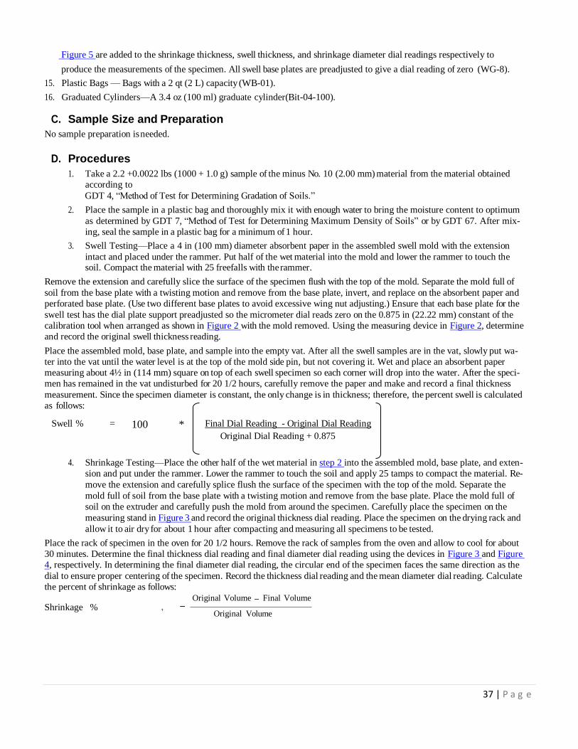
37 | P a g e
Original Volume Final Volume
Figure 5 are added to the shrinkage thickness, swell thickness, and shrinkage diameter dial readings respectively to
produce the measurements of the specimen. All swell base plates are preadjusted to give a dial reading of zero (WG-8).
15. Plastic Bags — Bags with a 2 qt (2 L) capacity (WB-01).
16. Graduated Cylinders—A 3.4 oz (100 ml) graduate cylinder(Bit-04-100).
C. Sample Size and Preparation
No sample preparation is needed.
D. Procedures
1. Take a 2.2 +0.0022 lbs (1000 + 1.0 g) sample of the minus No. 10 (2.00 mm) material from the material obtained
according to
GDT 4, “Method of Test for Determining Gradation of Soils.”
2. Place the sample in a plastic bag and thoroughly mix it with enough water to bring the moisture content to optimum
as determined by GDT 7, “Method of Test for Determining Maximum Density of Soils” or by GDT 67. After mix-
ing, seal the sample in a plastic bag for a minimum of 1 hour.
3. Swell Testing—Place a 4 in (100 mm) diameter absorbent paper in the assembled swell mold with the extension
intact and placed under the rammer. Put half of the wet material into the mold and lower the rammer to touch the soil. Compact the material with 25 freefalls with the rammer.
Remove the extension and carefully slice the surface of the specimen flush with the top of the mold. Separate the mold full of
soil from the base plate with a twisting motion and remove from the base plate, invert, and replace on the absorbent paper and
perforated base plate. (Use two different base plates to avoid excessive wing nut adjusting.) Ensure that each base plate for the
swell test has the dial plate support preadjusted so the micrometer dial reads zero on the 0.875 in (22.22 mm) constant of the
calibration tool when arranged as shown in Figure 2 with the mold removed. Using the measuring device in Figure 2, determine
and record the original swell thickness reading.
Place the assembled mold, base plate, and sample into the empty vat. After all the swell samples are in the vat, slowly put wa-
ter into the vat until the water level is at the top of the mold side pin, but not covering it. Wet and place an absorbent paper
measuring about 4½ in (114 mm) square on top of each swell specimen so each corner will drop into the water. After the speci-
men has remained in the vat undisturbed for 20 1/2 hours, carefully remove the paper and make and record a final thickness
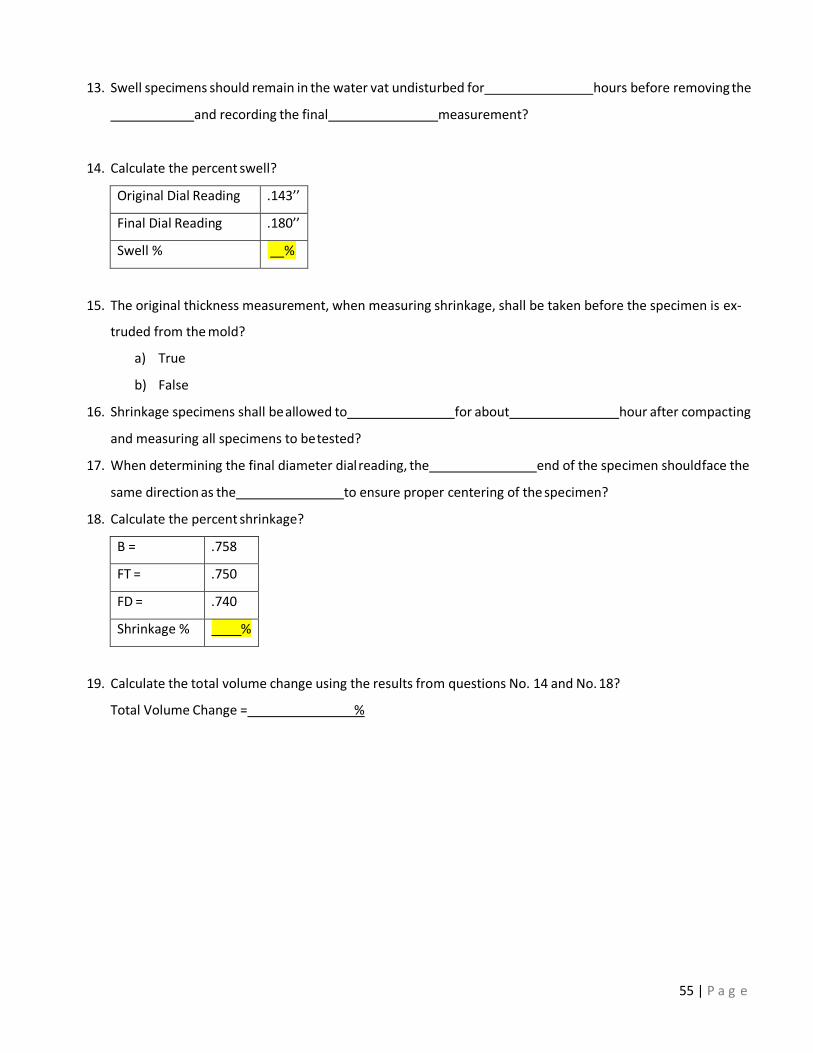
measurement. Since the specimen diameter is constant, the only change is in thickness; therefore, the percent swell is calculated
as follows:
Swell % = 100 * Final Dial Reading - Original Dial Reading
Original Dial Reading + 0.875
4. Shrinkage Testing—Place the other half of the wet material in step 2 into the assembled mold, base plate, and exten-
sion and put under the rammer. Lower the rammer to touch the soil and apply 25 tamps to compact the material. Re-
move the extension and carefully splice flush the surface of the specimen with the top of the mold. Separate the
mold full of soil from the base plate with a twisting motion and remove from the base plate. Place the mold full of
soil on the extruder and carefully push the mold from around the specimen. Carefully place the specimen on the
measuring stand in Figure 3 and record the original thickness dial reading. Place the specimen on the drying rack and
allow it to air dry for about 1 hour after compacting and measuring all specimens to be tested.
Place the rack of specimen in the oven for 20 1/2 hours. Remove the rack of samples from the oven and allow to cool for about
30 minutes. Determine the final thickness dial reading and final diameter dial reading using the devices in Figure 3 and Figure
4, respectively. In determining the final diameter dial reading, the circular end of the specimen faces the same direction as the
dial to ensure proper centering of the specimen. Record the thickness dial reading and the mean diameter dial reading. Calculate
the percent of shrinkage as follows:
Shrinkage % Original Volume

38 | P a g e

39 | P a g e
Original Volume, in3 = 0.7854 (4in)² (.250 in + B) [mm3 = 0.784 (101.6 mm) ² (6.35 mm + B)]
Final Volume, in3 = 0.7854 (3.250 in + FD)² (.250 in + FD) [mm3 = 0.7854 (82.55 mm + FD) ² (6.35 mm + FT)]
Where:
B = beginning dial reading for thickness FT = final
dial reading for thickness
FD = final dial reading for diameter
If desired, the following simplified formula may be used:
% sℎ𝑟inkage = 100 − (3.250 + 𝐹𝐷)2 𝑥 (.250 +FT)
. 16 (.250 + 𝐵)
5. Correction for Plus No. 10 (2.00 mm) Material—Where the soil contains particles larger than the No. 10 (2.00 mm)
sieve, the swell and shrinkage shall be corrected to reflect the percentage of Plus No. 10 (2.00 mm) material if the
applicable specifications require volume change results on the total sample. Conversion factors for correcting the
swell and shrinkage are given in the Volume Change Conversion Tables.
6. Total Volume Change—Calculate the total percentage points of volume change with the formula: Total Volume
Change = Percent Swell + Percent Shrinkage
E. Calculations
No calculations are needed.
F. Report
Report swell, shrinkage, and volume change to the nearest 0.0022 lb (1.0 g) for minus No. 10 (2.00 mm) or total sample, which-
ever is appropriate.

40 | P a g e

40 | P a g e
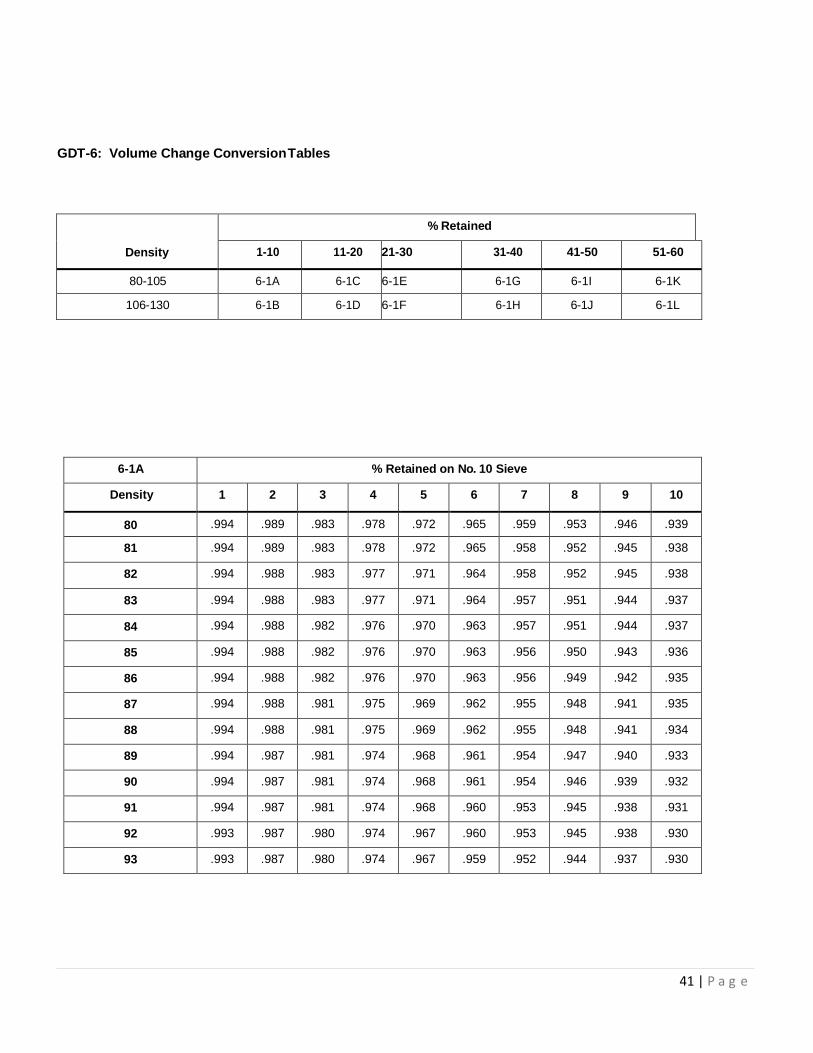
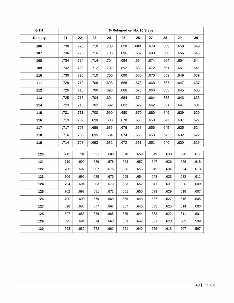
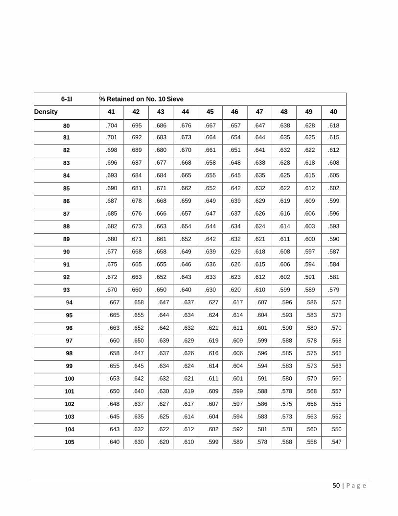
Volume Change Conversion Tables
This table on the next 12 pages gives a conversion factor for the related volume change of plus and minus No.10 materials com-
bined to the minus No. 10 material volume change.
Example Of Application:
Suppose a soil sample has 25 percent plus No 10 material. The minus No. 10 material has a proctor density of 100 pounds per
cubic foot and a shrinkage of 12 percent. To determine the composite soil (plus the minus No. 10 material) shrinkage, locate the
100 line in the left hand column, then follow this line right to the 25 percent column. The factor given is 0.804. Thus 12 x .804
= 9.6 percent shrinkage for the compositesoil.
41 | P a g e
GDT-6: Volume Change Conversion Tables
Density
% Retained
1-10 11-20 21-30 31-40 41-50 51-60
80-105 6-1A 6-1C 6-1E 6-1G 6-1I 6-1K
106-130 6-1B 6-1D 6-1F 6-1H 6-1J 6-1L
6-1A % Retained on No. 10 Sieve
Density 1 2 3 4 5 6 7 8 9 10
80 .994 .989 .983 .978 .972 .965 .959 .953 .946 .939
81 .994 .989 .983 .978 .972 .965 .958 .952 .945 .938
82 .994 .988 .983 .977 .971 .964 .958 .952 .945 .938
83 .994 .988 .983 .977 .971 .964 .957 .951 .944 .937
84 .994 .988 .982 .976 .970 .963 .957 .951 .944 .937
85 .994 .988 .982 .976 .970 .963 .956 .950 .943 .936
86 .994 .988 .982 .976 .970 .963 .956 .949 .942 .935
87 .994 .988 .981 .975 .969 .962 .955 .948 .941 .935
88 .994 .988 .981 .975 .969 .962 .955 .948 .941 .934
89 .994 .987 .981 .974 .968 .961 .954 .947 .940 .933
90 .994 .987 .981 .974 .968 .961 .954 .946 .939 .932
91 .994 .987 .981 .974 .968 .960 .953 .945 .938 .931
92 .993 .987 .980 .974 .967 .960 .953 .945 .938 .930
93 .993 .987 .980 .974 .967 .959 .952 .944 .937 .930

42 | P a g e
94 .993 .986 .980 .973 .966 .959 .952 .944 .937 .929
95 .993 .986 .980 .973 .966 .958 .951 .943 .936 .928
96 .993 .986 .980 .973 .966 .958 .951 .942 .935 .927
97 .993 .986 .980 .973 .966 .958 .950 .942 .934 .926
98 .993 .986 .979 .972 .965 .957 .950 .941 .934 .926
99 .993 .986 .979 .972 .965 .957 .949 .941 .933 .925
100 .993 .986 .979 .972 .965 .957 .949 .940 .932 .924
101 .993 .986 .979 .972 .965 .956 .948 .940 .932 .923
102 .993 .986 .978 .971 .964 .956 .948 .939 .931 .923
103 .993 .986 .978 .971 .964 .955 .947 .939 .931 .922
104 .993 .985 .978 .970 .963 .955 .947 .938 .930 .922
105 .993 .985 .978 .970 .963 .954 .946 .938 .930 .921
43 | P a g e
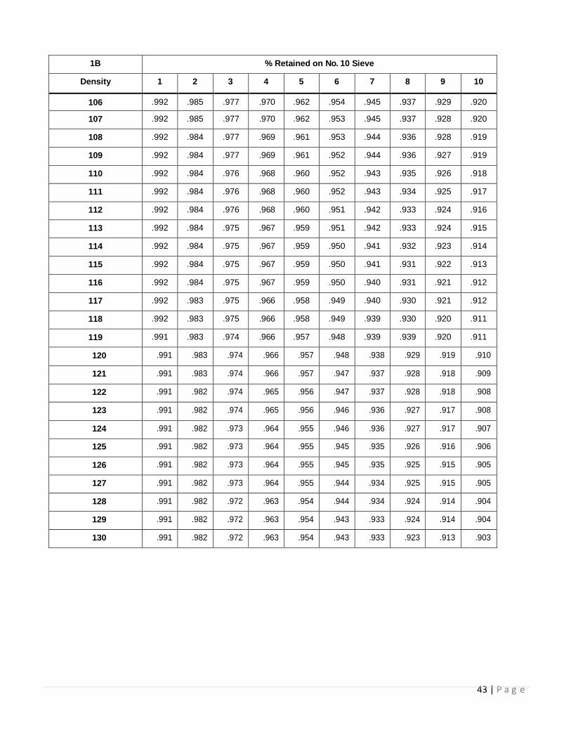
1B % Retained on No. 10 Sieve
Density 1 2 3 4 5 6 7 8 9 10
106 .992 .985 .977 .970 .962 .954 .945 .937 .929 .920
107 .992 .985 .977 .970 .962 .953 .945 .937 .928 .920
108 .992 .984 .977 .969 .961 .953 .944 .936 .928 .919
109 .992 .984 .977 .969 .961 .952 .944 .936 .927 .919
110 .992 .984 .976 .968 .960 .952 .943 .935 .926 .918
111 .992 .984 .976 .968 .960 .952 .943 .934 .925 .917
112 .992 .984 .976 .968 .960 .951 .942 .933 .924 .916
113 .992 .984 .975 .967 .959 .951 .942 .933 .924 .915
114 .992 .984 .975 .967 .959 .950 .941 .932 .923 .914
115 .992 .984 .975 .967 .959 .950 .941 .931 .922 .913
116 .992 .984 .975 .967 .959 .950 .940 .931 .921 .912
117 .992 .983 .975 .966 .958 .949 .940 .930 .921 .912
118 .992 .983 .975 .966 .958 .949 .939 .930 .920 .911
119 .991 .983 .974 .966 .957 .948 .939 .939 .920 .911
120 .991 .983 .974 .966 .957 .948 .938 .929 .919 .910
121 .991 .983 .974 .966 .957 .947 .937 .928 .918 .909
122 .991 .982 .974 .965 .956 .947 .937 .928 .918 .908
123 .991 .982 .974 .965 .956 .946 .936 .927 .917 .908
124 .991 .982 .973 .964 .955 .946 .936 .927 .917 .907
125 .991 .982 .973 .964 .955 .945 .935 .926 .916 .906
126 .991 .982 .973 .964 .955 .945 .935 .925 .915 .905
127 .991 .982 .973 .964 .955 .944 .934 .925 .915 .905
128 .991 .982 .972 .963 .954 .944 .934 .924 .914 .904
129 .991 .982 .972 .963 .954 .943 .933 .924 .914 .904
130 .991 .982 .972 .963 .954 .943 .933 .923 .913 .903

44 | P a g e
61C % Retained on No. 10 Sieve
Density 11 12 13 14 15 16 17 18 19 20
80 .933 .926 .919 .912 .905 .898 .891 .885 .878 .871
81 .932 .925 .918 .911 .904 .897 .890 .884 .877 .870
82 .931 .924 .917 .910 .903 .896 .889 .882 .875 .868
83 .931 .923 .916 .908 .901 .894 .887 .881 .874 .867
84 .930 .922 .915 .907 .900 .893 .886 .879 .872 .865
85 .929 .921 .914 .906 .899 .892 .885 .878 .871 .864
86 .928 .920 .913 .905 .898 .891 .884 .877 .870 .863
87 .927 .919 .912 .904 .897 .890 .883 .876 .868 .861
88 .926 .919 .911 .904 .896 .889 .881 .874 .867 .860
89 .925 .918 .910 .903 .895 .888 .880 .873 .865 .858
90 .924 .917 .909 .902 .894 .887 .879 .872 .864 .857
91 .923 .916 .908 .901 .893 .886 .878 .871 .863 .856
92 .922 .915 .907 .900 .892 .885 .877 .870 .862 .855
93 .922 .914 .907 .899 .891 .883 .876 .868 .861 .853
94 .921 .913 .906 .898 .890 .882 .875 .867 .860 .852
95 .920 .912 .905 .897 .889 .881 .874 .866 .859 .851
96 .919 .911 .904 .896 .888 .880 .873 .865 .858 .850
97 .918 .910 .903 .895 .887 .879 .872 .864 .857 .849
98 .918 .910 .902 .894 .886 .878 .870 .863 .855 .847
99 .917 .909 .901 .893 .885 .877 .869 .862 .854 .846
100 .916 .908 .900 .892 .884 .876 .868 .861 .853 .845
101 .915 .907 .899 .891 .883 .875 .867 .860 .852 .844
102 .915 .906 .898 .890 .882 .874 .866 .859 .850 .842
103 .914 .906 .898 .888 .881 .873 .865 .857 .849 .841
104 .914 .905 .897 .887 .880 .872 .864 .856 .847 .839
105 .913 .904 .896 .886 .879 .871 .863 .855 .846 .838

45 | P a g e
6-1D % Retained on No. 10 Sieve
Density 11 12 13 14 15 16 17 18 19 20
106 .912 .903 .895 .885 .878 .870 .862 .854 .845 .837
107 .911 .902 .894 .885 .877 .869 .861 .853 .844 .836
108 .911 .902 .894 .884 .876 .868 .859 .851 .842 .834
109 .910 .901 .893 .884 .875 .867 .585 .850 .841 .833
110 .909 .900 .892 .883 .874 .866 .857 .849 .840 .832
111 .908 .899 .891 .882 .873 .865 .856 .848 .839 .831
112 .907 .898 .890 .881 .872 .864 .855 .847 .838 .830
113 .906 .897 .889 .880 .871 .862 .854 .845 .837 .828
114 .905 .896 .888 .879 .870 .861 .853 .844 .836 .827
115 .904 .895 .887 .878 .869 .860 .852 .843 .835 .826
116 .903 .894 .886 .877 .868 .859 .851 .842 .834 .825
117 .903 .894 .885 .876 .867 .858 .850 .841 .833 .824
118 .902 .893 .884 .875 .866 .857 .848 .840 .831 .822
119 .902 .893 .883 .874 .865 .856 .847 .839 .830 .821
120 .901 .892 .882 .873 .864 .855 .846 .838 .829 .820
121 .901 .891 .881 .872 .863 .854 .845 .837 .828 .819
122 .899 .890 .880 .871 .862 .853 .844 .836 .827 .818
123 .899 .890 .880 .871 .862 .853 .844 .834 .825 .816
124 .898 .889 .879 .870 .861 .852 .843 .833 .824 .815
125 .897 .888 .878 .869 .860 .851 .842 .832 .823 .814
126 .896 .887 .877 .868 .859 .850 .841 .831 .822 .813
127 .895 .886 .876 .867 .857 .848 .839 .830 .821 .812
128 .895 .885 .875 .865 .856 .847 .838 .828 .819 .810
129 .894 .884 .874 .864 .854 .845 .836 .827 .818 .809
130 .893 .883 .873 .863 .853 .844 .835 .826 .817 .808

46 | P a g e
% Retained on No. 10 Sieve
Density 21 22 23 24 25 26 27 28 29 30
80 .864 .857 .850 .843 .836 .829 .821 .814 .807 .799
81 .863 .856 .848 .841 .834 .827 .819 .812 .805 .797
82 .861 .854 .847 .840 .833 .825 .817 .810 .803 .795
83 .860 .853 .845 .838 .831 .824 .816 .809 .801 .793
84 .858 .851 .844 .837 .830 .822 .814 .807 .799 .791
85 .857 .850 .842 .835 .828 .820 .812 .805 .797 .789
86 .855 .848 .841 .833 .826 .818 .810 .803 .795 .787
87 .854 .847 .839 .832 .825 .817 .809 .801 .793 .785
88 .853 .845 .838 .830 .823 .815 .807 .799 .791 .783
89 .851 .844 .836 .829 .822 .814 .806 .797 .789 .781
90 .850 .842 .835 .827 .820 .812 .804 .795 .787 .779
91 .849 .841 .834 .826 .819 .810 .802 .793 .785 .777
92 .847 .840 .833 .825 .817 .809 .801 .792 .784 .775
93 .846 .838 .831 .823 .816 .807 .799 .790 .782 .774
94 .844 .837 .830 .822 .814 .806 .798 .789 .781 .772
95 .843 .836 .828 .821 .813 .804 .796 .787 .779 .770
96 .842 .835 .826 .819 .811 .802 .794 .785 .777 .768
97 .841 .833 .825 .817 .809 .800 .792 .783 .775 .766
98 .839 .832 .823 .816 .808 .799 .790 .782 .773 .764
99 .838 .830 .822 .814 .806 .797 .788 .780 .771 .762
100 .837 .829 .820 .812 .804 .795 .786 .778 .769 .760
101 .836 .827 .819 .810 .802 .793 784 .776 .767 .758
102 .834 .826 .817 .809 .801 .791 .783 .774 .765 .756
103 .833 .824 .816 .807 .799 .790 .781 .772 .763 .754
104 .831 .823 .814 .806 .798 .789 .780 .770 .761 .752
105 .830 .821 .813 .804 .796 .787 .778 .768 .759 .750

47 | P a g e
6-1F % Retained on No. 10 Sieve
Density 21 22 23 24 25 26 27 28 29 30
106 .829 .820 .812 .803 .794 .785 .776 .766 .757 .748
107 .827 .818 .810 .801 .793 .783 .774 .764 .755 .746
108 .826 .817 .809 .800 .791 .782 .773 .763 .754 .744
109 .824 .815 .807 .798 .790 .780 .771 .761 .752 .742
110 .823 .814 .806 .797 .788 .778 .769 .759 .750 .740
111 .822 .813 .804 .795 .786 .776 .767 .757 .748 .738
112 .821 .812 .803 .794 .785 .775 .765 .756 .746 .736
113 .819 .810 .801 .792 .783 .773 .764 .754 .745 .735
114 .818 .809 .800 .791 . 782 .772 .762 .753 .743 .733
115 .817 .808 .798 .789 .780 .770 .760 .751 .741 .731
116 .816 .807 .797 .788 .799 .769 .759 .749 .739 .729
117 .815 .805 .796 .786 .777 .767 .757 .747 .737 .727
118 .813 .804 .794 .785 .776 .766 .756 .746 .736 .726
119 .812 .802 .793 .783 .774 .764 .754 .744 .734 .724
120 .811 .801 .792 .782 .773 .763 .753 .742 .732 .722
121 .810 .800 .791 .781 .771 .761 .751 .740 .730 .720
122 .808 .798 .789 .779 .770 .759 .749 .738 .728 .718
123 .807 .797 .788 .778 .768 .758 .748 .737 .727 .716
124 .805 .795 .786 .776 .767 .756 .746 .735 .725 .714
125 .804 .794 .785 .775 .765 .754 .744 .733 .723 .712
126 .803 .793 .784 .774 .764 .753 .742 .731 .721 .710
127 .802 .792 .782 .772 .762 .751 .741 .730 .719 .708
128 .800 .790 .781 .771 .761 .750 .739 .728 .718 .707
129 .799 .789 .781 .769 .759 .748 .737 .727 .716 .705
130 .798 .788 .778 .768 .758 .747 .736 .725 .714 .703

48 | P a g e
6-1G % Retained on No. 10 Sieve
Density 31 32 33 34 35 36 37 38 39 40
80 .791 .783 .775 .767 .759 .750 .741 .732 .723 .713
81 .789 .781 .773 .765 .757 .748 .738 .729 .720 .710
82 .787 .779 .771 .762 .755 .745 .736 .727 .717 .708
83 .785 .776 .768 .760 .752 .743 .733 .724 .715 .705
84 .783 .774 .766 .757 .749 .740 .731 .722 .712 .703
85 .781 .772 .764 .755 .747 .738 .728 .719 .709 .700
86 .779 .770 .762 .753 .745 .735 .726 .716 .707 .687
87 .777 .768 .760 .751 .742 .733 .723 .714 .704 .695
88 .774 .765 .757 .748 .740 .730 .721 .711 .702 .692
89 .772 .763 .755 .746 .737 .728 .718 .709 .699 .690
90 .770 .761 .753 .744 .735 .725 .716 .706 .697 .687
91 .768 .759 .751 .742 .732 .723 .713 .704 .694 .685
92 .766 .757 .748 .739 .730 .721 .711 .701 .692 .682
93 .764 .755 .746 .737 .727 .718 .708 .699 .689 .680
94 .762 .753 .743 .734 .725 .716 .706 .696 .687 .677
95 .760 .751 .741 .732 .722 .713 .703 .694 .684 .675
96 .758 .749 .739 .730 .720 .711 .701 .692 .682 .673
97 .756 .747 .737 .728 .718 .708 .699 .689 .680 .670
98 .754 .744 .735 .725 .715 .706 .696 .687 .677 .668
99 .752 .742 .733 .723 .713 .703 .694 .684 .675 .665
100 .750 .740 .731 .721 .711 .701 .692 .682 .673 .663
101 .748 .738 .729 .719 .709 .699 .690 .680 .671 .661
102 .746 .736 .727 .717 .707 .697 .688 .678 .668 .658
103 .744 .734 .724 .714 .704 .695 .685 .675 .666 .656
104 .742 .732 .722 .712 .702 .693 .683 .673 .663 .653
105 .740 .730 .720 .710 .700 .691 .681 .671 .661 .651
49 | P a g e
6-1H % Retained on No. 10 Sieve
Density 21 22 23 24 25 26 27 28 29 30
106 .738 .728 .718 .708 .698 689 .679 .669 .659 .649
107 .736 .726 .716 .706 .696 .687 .688 .666 .656 .646
108 .734 .724 .714 .704 .694 .684 .674 .664 .654 .644
109 .732 .722 .712 .702 .692 .682 .672 .661 .651 .641
110 .730 .720 .710 .700 .690 .680 .670 .659 .649 .639
111 .728 .718 .708 .698 .688 .678 .668 .657 .647 .637
112 .726 .716 .706 .696 .686 .676 .666 .655 .645 .635
113 .725 .715 .704 .694 .684 .674 .664 .653 .643 .633
114 .723 .713 .702 .692 .682 .672 .662 .651 .641 .631
115 .721 .711 .700 .690 .680 .670 .660 .649 .639 .629
116 .719 .709 .698 .688 .678 .668 .658 .647 .637 .627
117 .717 .707 .696 .686 .676 .666 .656 .645 .635 .624
118 .716 .705 .695 .684 .674 .663 .653 .642 .632 .622
119 .714 .703 .693 .682 .672 .661 .651 .640 .630 .619
120 .712 .701 .691 .680 .670 .659 .649 .638 .628 .617
121 .710 .699 .689 .678 .668 .657 .647 .636 .626 .615
122 .708 .697 .687 .676 .666 .655 .645 .634 .624 .613
123 .706 .696 .685 .675 .665 .654 .643 .633 .622 .611
124 .704 .694 .683 .673 .663 .652 .641 .631 .620 .609
125 .702 .692 .681 .671 .661 .650 .639 .629 .618 .607
126 .700 .690 .679 .669 .659 .648 .637 .627 .616 .605
127 .698 .688 .677 .667 .657 .646 .635 .625 .614 .603
128 .697 .686 .676 .665 .655 .644 .633 .622 .611 .601
129 .695 .684 .674 .663 .653 .642 .631 .620 .609 .599
130 .693 .682 .672 .661 .651 .640 .629 .618 .607 .597
50 | P a g e
6-1I % Retained on No. 10 Sieve
Density 41 42 43 44 45 46 47 48 49 40
80 .704 .695 .686 .676 .667 .657 .647 .638 .628 .618
81 .701 .692 .683 .673 .664 .654 .644 .635 .625 .615
82 .698 .689 .680 .670 .661 .651 .641 .632 .622 .612
83 .696 .687 .677 .668 .658 .648 .638 .628 .618 .608
84 .693 .684 .684 .665 .655 .645 .635 .625 .615 .605
85 .690 .681 .671 .662 .652 .642 .632 .622 .612 .602
86 .687 .678 .668 .659 .649 .639 .629 .619 .609 .599
87 .685 .676 .666 .657 .647 .637 .626 .616 .606 .596
88 .682 .673 .663 .654 .644 .634 .624 .614 .603 .593
89 .680 .671 .661 .652 .642 .632 .621 .611 .600 .590
90 .677 .668 .658 .649 .639 .629 .618 .608 .597 .587
91 .675 .665 .655 .646 .636 .626 .615 .606 .594 .584
92 .672 .663 .652 .643 .633 .623 .612 .602 .591 .581
93 .670 .660 .650 .640 .630 .620 .610 .599 .589 .579
94 .667 .658 .647 .637 .627 .617 .607 .596 .586 .576
95 .665 .655 .644 .634 .624 .614 .604 .593 .583 .573
96 .663 .652 .642 .632 .621 .611 .601 .590 .580 .570
97 .660 .650 .639 .629 .619 .609 .599 .588 .578 .568
98 .658 .647 .637 .626 .616 .606 .596 .585 .575 .565
99 .655 .645 .634 .624 .614 .604 .594 .583 .573 .563
100 .653 .642 .632 .621 .611 .601 .591 .580 .570 .560
101 .650 .640 .630 .619 .609 .599 .588 .578 .568 .557
102 .648 .637 .627 .617 .607 .597 .586 .575 .656 .555
103 .645 .635 .625 .614 .604 .594 .583 .573 .563 .552
104 .643 .632 .622 .612 .602 .592 .581 .570 .560 .550
105 .640 .630 .620 .610 .599 .589 .578 .568 .558 .547

51 | P a g e
6-1J % Retained on No. 10 Sieve
Density 41 42 43 44 45 46 47 48 49 50
106 .638 .628 .618 .607 .597 .587 .576 .566 .555 .545
107 .636 .625 .615 .605 .594 .584 .573 .563 .553 .542
108 .633 .623 .613 .602 .592 .582 .571 .561 .550 .540
109 .631 .620 .610 .600 .589 .579 .568 .558 .548 .537
110 .629 .618 .608 .597 .587 .577 .566 .556 .545 .535
111 .627 .616 .606 .595 .585 .575 .564 .554 .543 .533
112 .625 .614 .604 .593 .582 .572 .561 .552 .540 .531
113 .622 .611 .601 .590 .580 .570 .559 .549 .538 .528
114 .620 .609 .599 .588 .577 .567 .556 .546 .535 .525
115 .618 .607 .597 .586 .575 .565 .554 .544 .533 .523
116 .616 .605 .595 .584 .573 .563 .552 .542 .531 .521
117 .613 .603 .592 .582 .571 .560 .550 .540 .529 .519
118 .611 .600 .590 .579 .568 .558 .549 .537 .527 .517
119 .608 .598 .587 .577 .566 .555 .546 .535 .525 .515
120 .606 .596 .585 .575 .564 .553 .544 .533 .523 .513
121 .604 .594 .583 .573 .562 .551 .542 .531 .521 .511
122 .602 .592 .581 .571 .560 .549 .540 .529 .519 .508
123 .600 .590 .579 .569 .558 .547 .537 .526 .516 .506
124 .598 .588 .577 .567 .556 .545 .535 .524 .514 .503
125 .596 .586 .575 .565 .554 .543 .533 .522 .512 .501
126 .594 .584 .573 .563 .552 .541 .531 .520 .510 .500
127 .592 .582 .571 .561 .550 .539 .529 .518 .508 .498
128 .590 .580 .569 .558 .548 .537 .526 .515 .505 .497
129 .588 .578 .567 .556 .546 .535 .524 .513 .503 .495
130 .586 .576 .565 .554 .544 .533 .522 .511 .501 .494

52 | P a g e
6-1K % Retained on No. 10 Sieve
Density 51 52 53 54 55 56 57 58 59 60
80 .607 .597 .587 .576 .566 .555 .545 .534 .523 .513
81 .604 .594 .584 .573 .563 .552 .542 .530 .519 .509
82 .601 .591 .581 .570 .560 .549 .538 .527 .516 .505
83 .598 .587 .577 .566 .556 .545 .535 .523 .512 .502
84 .595 .584 .574 .563 .553 .542 .531 .520 .509 .498
85 .592 .581 .571 .560 .550 .539 .528 .516 .505 .494
86 .589 .578 .568 .557 .547 .536 .525 .513 .502 .491
87 .586 .575 .564 .554 .544 .533 .522 .510 .499 .488
88 .583 .572 .562 .551 .541 .530 .519 .507 .496 .485
89 .580 .568 .559 .548 .538 .527 .516 .504 .493 .482
90 .577 .566 .556 .545 .535 .524 .513 .501 .490 .479
91 .574 .563 .553 .542 .532 .521 .510 .498 .487 .476
92 .571 .560 .550 .539 .529 .518 .507 .495 .484 .473
93 .569 .558 .548 .537 .527 .515 .504 .492 .481 .469
94 .566 .555 .545 .534 .524 .512 .501 .489 .478 .466
95 .563 .552 .542 .531 .521 .509 .498 .486 .475 .463
96 .560 .549 .539 .528 .518 .506 .495 .483 .472 .460
97 .558 .547 .537 .526 .516 .504 .492 .480 .469 .457
98 .555 .544 .534 .523 .513 .501 .490 .478 .466 .454
99 .553 .542 .532 .521 .511 .499 .487 .475 .463 .451
100 .550 .539 .527 .518 .508 .496 .484 .472 .460 .448
101 .547 .536 .526 .515 .505 .493 .481 .469 .457 .445
102 .544 .534 .523 .512 .502 .490 .478 .466 .454 .443
103 .542 .531 .521 .510 .500 .488 .476 .464 .452 .440
104 .539 .529 .518 .507 .497 .485 .473 .461 .449 .438
105 .536 .526 .515 .504 .494 .482 .470 .458 .446 .435

53 | P a g e
6-1L % Retained on No. 10 Sieve
Density 51 52 53 54 55 56 57 58 59 60
106 .534 .523 .512 .501 .491 .479 .467 .455 .444 .432
107 .531 .521 .510 .499 .488 .476 .465 .453 .441 .430
108 .529 .518 .507 .496 .486 .474 .462 .450 .439 .427
109 .526 .516 .505 .494 .483 .471 .460 .448 .436 .425
110 .524 .513 .502 .491 .480 .468 .457 .445 .434 .422
111 .522 .511 .499 .488 .477 .466 .454 .443 .431 .420
112 .519 .508 .497 .486 .475 .463 .452 .440 .429 .417
113 .517 .506 .494 .483 .472 .461 .449 .438 .426 .415
114 .514 .503 .492 .481 .470 .458 .447 .435 .424 .412
115 .512 .501 .489 .478 .467 .456 .444 .433 .421 .410
116 .510 .499 .487 .476 .465 .454 .442 .431 .419 .408
117 .508 .497 .485 .474 .462 .451 .439 .428 .416 .405
118 .505 .494 .482 .471 .460 .449 .437 .426 .414 .403
119 .503 .592 .480 .469 .457 .446 .434 .423 .411 .400
120 .501 .490 .478 .467 .455 .444 .432 .421 .409 .398
121 .499 .488 .476 .465 .453 .442 .430 .419 .407 .396
122 .496 .485 .473 .462 .450 .439 .428 .417 .405 .394
123 .494 .483 .471 .460 .448 .437 .425 .414 .403 .392
124 .491 .480 .468 .457 .445 .434 .423 .412 .401 .390
125 .489 .478 .466 .455 .443 .432 .421 .410 .399 .388
126 .487 .476 .464 .453 .441 .430 .419 .408 .397 .386
127 .485 .474 .462 .451 .439 .428 .417 .406 .395 .384
128 .482 .471 .459 .448 .436 .425 .414 .403 .392 .381
129 .480 .469 .457 .446 .434 .423 .412 .401 .390 .379
130 .478 .467 .455 .444 .432 .421 .410 .399 .388 .377

54 | P a g e
STUDY QUESTIONS
GDT 6
Determining the Volume Change of Soils
1. It is ok to use the same mold for both the shrinkage test and the swell test?
a) True
b) False
2. The metal rammer used for this test shall have a in diameter flatcircular face and weigh lbs.
3. When using a mechanical rammer, check the tolerances semi-annually using the procedures in AASHTO
?
4. What is the minimum depth of the water vat required for thistest?
5. A flat perforated metal plate with 3/8 in (10 mm) diameter holes located symmetrically under each
specimen shall be used to and shrinkage specimens.
6. The three measuring devices shall be readable to and sensitive to in.?
7. The following device is used to measure ?
8. A sample mass of should be taken from the materials passing the 2.00-mm (No. 10) sieve
as obtained according to ?
9. Optimum moisture content used for this procedure should be determined by or ?
10. The test sample should be allowed to stand, in a , at moisture content, for
a of 1 hour?
11. How many freefalls of the hammer are required to compact the swell testspecimen?
12. Swell test base plates should be preadjusted, so the micrometer reads on the con-
stant of the calibration tool, with the removed.
55 | P a g e
13. Swell specimens should remain in the water vat undisturbed for hours before removing the
and recording the final measurement?
14. Calculate the percent swell?
Original Dial Reading .143’’
Final Dial Reading .180’’
Swell % %
15. The original thickness measurement, when measuring shrinkage, shall be taken before the specimen is ex-
truded from the mold?
a) True
b) False
16. Shrinkage specimens shall be allowed to for about hour after compacting
and measuring all specimens to be tested?
17. When determining the final diameter dial reading, the end of the specimen should face the
same direction as the to ensure proper centering of the specimen?
18. Calculate the percent shrinkage?
B = .758
FT = .750
FD = .740
Shrinkage % %
19. Calculate the total volume change using the results from questions No. 14 and No. 18?
Total Volume Change = %

56 | P a g e
PERFORMANCE CHECKLIST
GDT 6
Determining the Volume Change of Soils
1. Place sample into a plastic bag and thoroughly mix it with enough water to bring the moisture content to
optimum.
2. Seal the bag and allow the test sample to stand for a minimum of 1hour.
Swell Test
3. Place a 4 in. (100 mm) diameter absorbent paper into the assembled swell mold.
4. Place the swell mold under the rammer and place 1/2 of the test sample into the mold.
5. Lower the rammer to touch the soil and compact the test sample with 25 freefalls of therammer.
6. Remove the mold extension and slice the surface of the specimen flush with the top of the mold.
7. Separate the mold from the base plate, invert, and place onto the absorbent paper and perforated base
plate.
8. Use the measuring device in Figure 2 to determine the original swell thicknessreading.
9. Place the assembled mold, base plate, and test sample into a emptyvat.
10. Slowly fill the vat until the water level is at the top of the mold side pin, but not covering it.
11. Place a wet, absorbent paper, measuring about 4 ½ in. (114 mm) square, on top of the swell specimen so
that the corner will be in the water.
12. Allow test specimen to remain in the vat undisturbed for 20 and ½ hours.
13. Remove the absorbent paper and record a final thickness measurement.
Shrinkage Test
14. Place remaining 1/2 of the test sample into the assembled mold, base plate, and extension.
15. Lower the rammer to touch the soil and compact the test sample with 25 freefalls of the rammer.
16. Remove the mold extension and slice the surface of the specimen flush with the top of the mold.
17. Separate the mold, full of soil, from the base plate.
18. Use an extruder to remove the soil cake from the mold.
19. Place the test sample on the measuring stand in Figure 3 and record the original shrinkage thickness dial
reading.

57 | P a g e
20. Place the test specimen on a drying rack and allow to air dry for about 1hour.
21. Place the drying rack, and test specimen, into the oven at a temperature 230 ° ± 9 °F (110 ° ± 5 °C) for 20 and
1/2 hours.
22. Remove the rack, and test specimen, from the oven and allow to cool for about 30 minutes.
23. Determine the final thickness dial reading and the final diameter dial reading using the devices in Figure 3
and Figure 4.

58 | P a g e
SECTION 7
GDT 7
Determining Maximum Density of Soils
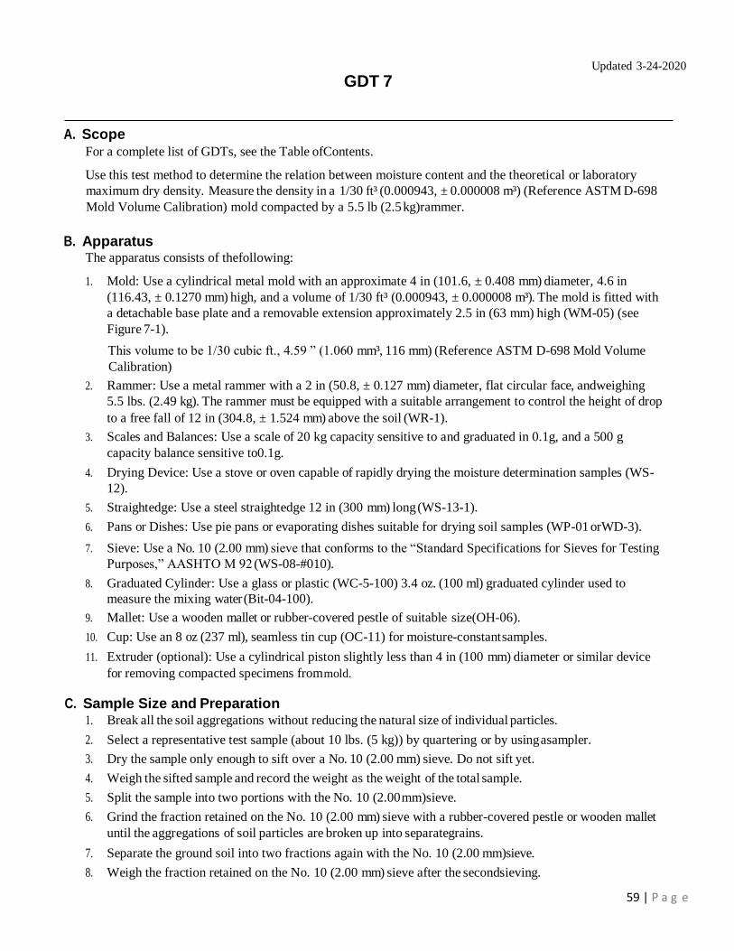
59 | P a g e
GDT 7 Updated 3-24-2020
A. Scope For a complete list of GDTs, see the Table ofContents.
Use this test method to determine the relation between moisture content and the theoretical or laboratory
maximum dry density. Measure the density in a 1/30 ft³ (0.000943, ± 0.000008 m³) (Reference ASTM D-698
Mold Volume Calibration) mold compacted by a 5.5 lb (2.5 kg)rammer.
B. Apparatus
The apparatus consists of thefollowing:
1. Mold: Use a cylindrical metal mold with an approximate 4 in (101.6, ± 0.408 mm) diameter, 4.6 in
(116.43, ± 0.1270 mm) high, and a volume of 1/30 ft³ (0.000943, ± 0.000008 m³). The mold is fitted with
a detachable base plate and a removable extension approximately 2.5 in (63 mm) high (WM-05) (see
Figure 7-1).
This volume to be 1/30 cubic ft., 4.59 ” (1.060 mm³, 116 mm) (Reference ASTM D-698 Mold Volume
Calibration)
2. Rammer: Use a metal rammer with a 2 in (50.8, ± 0.127 mm) diameter, flat circular face, andweighing
5.5 lbs. (2.49 kg). The rammer must be equipped with a suitable arrangement to control the height of drop
to a free fall of 12 in (304.8, ± 1.524 mm) above the soil (WR-1).
3. Scales and Balances: Use a scale of 20 kg capacity sensitive to and graduated in 0.1g, and a 500 g
capacity balance sensitive to0.1g.
4. Drying Device: Use a stove or oven capable of rapidly drying the moisture determination samples (WS-
12).
5. Straightedge: Use a steel straightedge 12 in (300 mm) long (WS-13-1).
6. Pans or Dishes: Use pie pans or evaporating dishes suitable for drying soil samples (WP-01 orWD-3).
7. Sieve: Use a No. 10 (2.00 mm) sieve that conforms to the “Standard Specifications for Sieves for Testing
Purposes,” AASHTO M 92 (WS-08-#010).
8. Graduated Cylinder: Use a glass or plastic (WC-5-100) 3.4 oz. (100 ml) graduated cylinder used to
measure the mixing water (Bit-04-100).
9. Mallet: Use a wooden mallet or rubber-covered pestle of suitable size(OH-06).
10. Cup: Use an 8 oz (237 ml), seamless tin cup (OC-11) for moisture-constant samples.
11. Extruder (optional): Use a cylindrical piston slightly less than 4 in (100 mm) diameter or similar device
for removing compacted specimens from mold.
C. Sample Size and Preparation 1. Break all the soil aggregations without reducing the natural size of individual particles.
2. Select a representative test sample (about 10 lbs. (5 kg)) by quartering or by using asampler.
3. Dry the sample only enough to sift over a No. 10 (2.00 mm) sieve. Do not sift yet.
4. Weigh the sifted sample and record the weight as the weight of the total sample.
5. Split the sample into two portions with the No. 10 (2.00 mm)sieve.
6. Grind the fraction retained on the No. 10 (2.00 mm) sieve with a rubber-covered pestle or wooden mallet
until the aggregations of soil particles are broken up into separategrains.
7. Separate the ground soil into two fractions again with the No. 10 (2.00 mm)sieve.
8. Weigh the fraction retained on the No. 10 (2.00 mm) sieve after the secondsieving.

59 | P a g e

60 | P a g e
9. Record the weight as the weight of material retained on the No. 10 (2.00 mm) sieve.
D. Procedures
1. Thoroughly mix both fractions that passed the No. 10 (2.00 mm) sieve in both sievingoperations.
2. Take a 6.6 lb (3000 g) sample from the minus No. 10 (2.00 mm) material by quartering or by using a
sampler.
3. Attach the extension to thecylinder.
4. Compact the sample in the cylinder in three equallayers.
a. Compact each layer with 25 blows from the rammer dropped from 1 ft (304.8 mm) above thesoil.
b. Rest the mold on a uniform, rigid foundation, such as a concrete block weighing at least 200 lbs (90
kg).
c. Uniformly distribute the blows over the surface of the compactedlayer.
d. Remove the soil that adheres to the face of the rammer after every 25th blow.
5. After compacting, remove the extension and baseplate.
6. Carefully level the compacted soil to the top and bottom of the cylinder with the straightedge.
7. Weigh the cylinder and sampletogether.
8. Calculate the wet weight of the compacted soil in pounds per cubic foot as follows:
Wet Weight of Compacted Soil (lbs./ft3) = (Ws-Wc)/453.6 or (Ws-Wc) * Mold Factor or (Ws-Wc) *
C.F.C V 453.6
V = Volume in lbs./ft
3 of the Mold as calibrated Using (Reference ASTM D-698 Mold Volume
Calibration)
Mold Factor = calculated 1/volumelbs./ft3
C.F.C = Correction Factor Conversion = Mold Factor/453.6
Ws = weight of the compacted soil and mold, in grams
Wc = weight of the mold, in grams
If you weighed in grams, dividing by 453.6 converts grams to pounds. This will give you the wet weight
in pounds per cubic foot.
9. Remove the compacted soil from the cylinder and slice it vertically through its center.
10. Take a 100 g sample from the center and weigh it immediately.
11. Dry the sample to a constant weight.
12. Calculate the moisture content of the soil asfollows:
13. Moisture (%) = A - B x 100
B
where:
A = weight of the wet soil
B = weight of the dry soil
14. Thoroughly pulverize the remaining material from the compactedsample.
15. Add enough water to increase the moisture content of the soil in predetermined increments (1 percent to2
percent for sandy soils, 2 percent to 3 percent for clay soils).
a. For a 5.94 lb (2.7 kg) sample, add 0.9 oz (27 ml) of water to increase the moisture content by 1
percent.
b. For a 6.6 lb (3000 g) sample, add 1 oz (30 ml) of water.
16. Repeat steps 1 through 13 again, taking a moisture sample after each determination.

61 | P a g e
17. Repeat the procedure until the soil becomes very wet and the wet weight of the compacted soil
substantiallydecreases.
E. Calculations (CVP 7) 1. Calculate wet density:
Wet Density = (Ws - Wc)/453.6 or (Ws - Wc) * Mold Factor or (Ws – Wc) * C.F.C.
V 453.6
where:
V = Volume of the Mold as calibrated Using (Ref. ASTM D-698, CVP 7)
Mold Factor = Calculated 1/volume lbs/ft3 (Ref. CVP 7)
C.F.C = Correction Factor Conversion (GDOT Correction Factor) = Mold Factor/453.6 (Ref. CVP
7)
Wc = Weight of mold in grams
Ws = Weight of mold + wet soil in grams
2. Calculate percent moisture:
% Moisture = A - B x 100
B
where:
A = Weight of wet soil
B = Weight of dry soil
3. Calculate the density (dry weight), in pounds per cubic foot (kilograms per cubic meter), of the compacted
soil as follows:
English—Dry Density (lb/ft3)
= Ww x 100
M + 100
where:
Ww = wet weight of the compacted soil, in pounds per cubic foot (Procedures, step D.8)
M = moisture content, in percent, at which the wet weight was determined (Procedures, step D.12)
4. Moisture-Density Relationship
a. Calculate and record the percent moisture and dry density for each determination in theseries.
b. When using the moisture-density relationship for compactioncontrol:
i. Plot a moisture-density curve by plotting the dry densities against their respective
moisture contents.
ii. Draw a smooth curve through the resultingpoints.
iii. The peak of the curve represents the maximum dry density of the material beingtested,
andthe moisture content at this point represents the optimum moisturecontent.
c. For classification purposes, interpret the maximum dry density as the highest densityobtained in
the test series, and the optimum moisture as the moisture content at that respective density.
5. Correction for Plus No. 10 (2.00 mm) Material
d. If the soil contains material retained on the No. 10 (2.00 mm) sieve and the specifications show
density requirements on the total sample, you must correct the maximum dry density to reflect the
percentage of Plus No. 10 (2.00 mm) material.
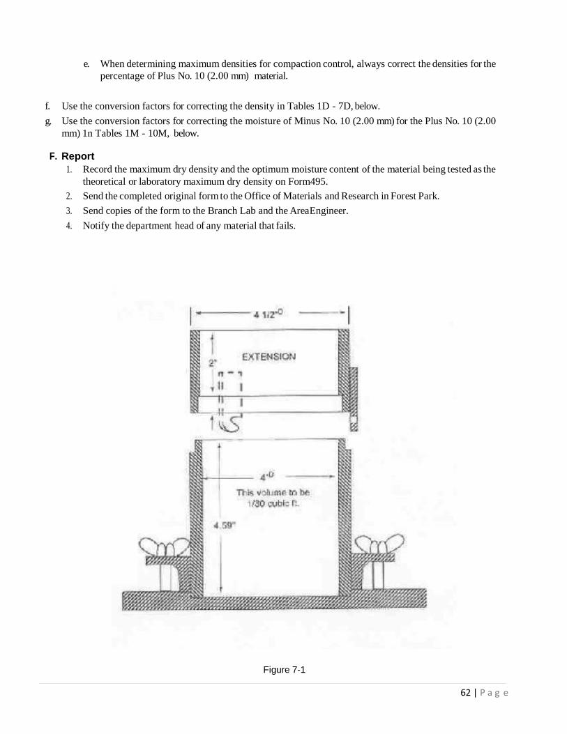
62 | P a g e
e. When determining maximum densities for compaction control, always correct the densities for the
percentage of Plus No. 10 (2.00 mm) material.
f. Use the conversion factors for correcting the density in Tables 1D - 7D, below.
g. Use the conversion factors for correcting the moisture of Minus No. 10 (2.00 mm) for the Plus No. 10 (2.00
mm) 1n Tables 1M - 10M, below.
F. Report
1. Record the maximum dry density and the optimum moisture content of the material being tested as the
theoretical or laboratory maximum dry density on Form495.
2. Send the completed original form to the Office of Materials and Research in Forest Park.
3. Send copies of the form to the Branch Lab and the AreaEngineer.
4. Notify the department head of any material that fails.
Figure 7-1

GDT 7 TABLE 1D FOR % PLUS NO. 10 IN TOTAL
SAMPLE
% Plus No. 10 Material by Weight in Total Sample
-10
Density
1 2 3 4 5 6 7
130 130.1 130.2 130.3 130.4 130.5 130.6 130.7
129 129.1 129.2 129.3 129.4 129.5 129.6 129.7
128 128.1 128.2 128.3 128.5 128.6 128.7 128.8
127 127.1 127.3 127.4 127.5 127.6 127.8 127.9
126 126.1 126.3 126.4 126.5 126.7 126.8 126.9
125 125.2 125.3 125.4 125.6 125.7 125.9 126.0
124 124.2 124.3 124.5 124.6 124.8 124.9 125.1
123 123.2 123.3 123.5 123.6 123.8 124.0 124.1
122 122.2 122.3 122.5 122.7 122.9 123.0 123.2
121 121.2 121.4 121.5 121.7 121.9 122.1 122.2
120 120.2 120.4 120.6 120.7 120.9 121.1 121.3
119 119.2 119.4 119.6 119.8 120.0 120.2 120.4
118 118.2 118.4 118.6 118.8 119.0 119.2 119.4
117 117.2 117.4 117.6 117.9 118.1 118.3 118.5
116 116.2 116.4 116.7 116.9 117.1 117.3 117.6
115 115.2 115.5 115.7 115.9 116.2 116.4 116.6
114 114.3 114.5 114.7 115.0 115.2 115.4 115.7
113 113.3 113.5 113.8 114.0 114.3 114.5 114.8
112 112.3 112.5 112.8 113.0 113.3 113.6 113.8
111 111.3 111.5 111.8 112.1 112.3 112.6 112.9
110 110.3 110.6 110.8 111.1 111.4 111.7 111.9
109 109.3 109.6 109.9 110.1 110.4 110.7 111.0
108 108.3 108.6 108.9 109.2 109.5 109.8 110.1
107 107.3 107.6 107.9 108.2 108.5 108.8 109.1
106 106.3 106.6 106.9 107.3 107.6 107.9 108.2
105 105.3 105.6 106.0 106.3 106.6 106.9 107.3
104 104.3 104.7 105.0 105.3 105.7 106.0 106.3
103 103.3 103.7 104.0 104.4 104.7 105.0 105.4
102 102.4 102.7 103.0 103.4 103.7 104.1 104.4
101 101.4 101.7 102.1 102.4 102.8 103.1 103.5
100 100.4 100.7 101.1 101.5 101.8 102.2 102.6
99 99.4 99.8 100.1 100.5 100.9 101.3 101.6
98 98.4 98.8 99.2 99.5 99.9 100.3 100.7
97 97.4 97.8 98.2 98.6 99.0 99.4 99.8
96 96.4 96.8 97.2 97.6 98.0 98.4 98.8
95 95.4 95.8 96.2 96.6 97.1 97.5 97.9
94 94.4 94.8 95.3 95.7 96.1 96.5 96.9
93 93.4 93.9 94.3 94.7 95.1 95.6 96.0
92 92.4 92.9 93.3 93.8 94.2 94.6 95.1
91 91.5 91.9 92.3 92.8 93.2 93.7 94.1
90 90.5 90.9 91.4 91.8 92.3 92.7 93.2
89 89.5 89.9 90.4 90.9 91.3 91.8 92.3
88 88.5 88.9 89.4 89.9 90.4 90.8 91.3
63 | P a g e

GDT 7
87 87.5 88.0 88.4 88.9 89.4 89.9 90.4
86 86.5 87.0 87.5 88.0 88.5 89.0 89.4
85 85.5 86.0 86.5 87.0 87.5 88.0 88.5
84 84.5 85.0 85.5 86.0 86.6 87.1 87.6
83 83.5 84.0 84.6 85.1 85.6 86.1 86.6
82 82.5 83.1 86.3 84.1 84.6 85.2 85.7
81 81.5 82.1 82.6 83.1 83.7 84.2 84.8
64 | P a g e
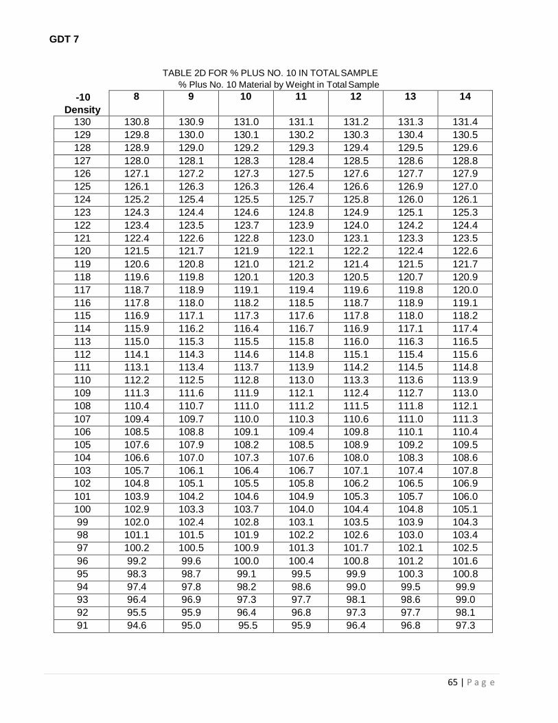
65 | P a g e
GDT 7
TABLE 2D FOR % PLUS NO. 10 IN TOTAL SAMPLE
% Plus No. 10 Material by Weight in Total Sample
-10
Density
8 9 10 11 12 13 14
130 130.8 130.9 131.0 131.1 131.2 131.3 131.4
129 129.8 130.0 130.1 130.2 130.3 130.4 130.5
128 128.9 129.0 129.2 129.3 129.4 129.5 129.6
127 128.0 128.1 128.3 128.4 128.5 128.6 128.8
126 127.1 127.2 127.3 127.5 127.6 127.7 127.9
125 126.1 126.3 126.3 126.4 126.6 126.9 127.0
124 125.2 125.4 125.5 125.7 125.8 126.0 126.1
123 124.3 124.4 124.6 124.8 124.9 125.1 125.3
122 123.4 123.5 123.7 123.9 124.0 124.2 124.4
121 122.4 122.6 122.8 123.0 123.1 123.3 123.5
120 121.5 121.7 121.9 122.1 122.2 122.4 122.6
119 120.6 120.8 121.0 121.2 121.4 121.5 121.7
118 119.6 119.8 120.1 120.3 120.5 120.7 120.9
117 118.7 118.9 119.1 119.4 119.6 119.8 120.0
116 117.8 118.0 118.2 118.5 118.7 118.9 119.1
115 116.9 117.1 117.3 117.6 117.8 118.0 118.2
114 115.9 116.2 116.4 116.7 116.9 117.1 117.4
113 115.0 115.3 115.5 115.8 116.0 116.3 116.5
112 114.1 114.3 114.6 114.8 115.1 115.4 115.6
111 113.1 113.4 113.7 113.9 114.2 114.5 114.8
110 112.2 112.5 112.8 113.0 113.3 113.6 113.9
109 111.3 111.6 111.9 112.1 112.4 112.7 113.0
108 110.4 110.7 111.0 111.2 111.5 111.8 112.1
107 109.4 109.7 110.0 110.3 110.6 111.0 111.3
106 108.5 108.8 109.1 109.4 109.8 110.1 110.4
105 107.6 107.9 108.2 108.5 108.9 109.2 109.5
104 106.6 107.0 107.3 107.6 108.0 108.3 108.6
103 105.7 106.1 106.4 106.7 107.1 107.4 107.8
102 104.8 105.1 105.5 105.8 106.2 106.5 106.9
101 103.9 104.2 104.6 104.9 105.3 105.7 106.0
100 102.9 103.3 103.7 104.0 104.4 104.8 105.1
99 102.0 102.4 102.8 103.1 103.5 103.9 104.3
98 101.1 101.5 101.9 102.2 102.6 103.0 103.4
97 100.2 100.5 100.9 101.3 101.7 102.1 102.5
96 99.2 99.6 100.0 100.4 100.8 101.2 101.6
95 98.3 98.7 99.1 99.5 99.9 100.3 100.8
94 97.4 97.8 98.2 98.6 99.0 99.5 99.9
93 96.4 96.9 97.3 97.7 98.1 98.6 99.0
92 95.5 95.9 96.4 96.8 97.3 97.7 98.1
91 94.6 95.0 95.5 95.9 96.4 96.8 97.3

66 | P a g e
GDT 7
90 93.6 94.1 94.6 95.0 95.5 95.9 96.4
89 92.7 93.2 93.7 94.1 94.6 95.0 95.5
88 91.8 92.3 92.7 93.2 93.7 94.2 94.6
87 90.9 91.3 91.8 92.3 92.8 93.3 93.8
86 89.9 90.4 90.9 91.4 91.9 92.4 92.9
85 89.0 89.5 90.0 90.5 91.0 91.5 92.0
84 88.1 88.6 89.1 89.6 90.1 90.6 91.1
83 87.2 87.7 88.2 88.7 89.2 89.7 90.3
82 86.2 86.8 87.3 87.8 88.3 88.9 89.4
81 85.3 85.8 86.4 89.9 87.4 88.0 88.5

67 | P a g e
GDT 7
TABLE 3D FOR % PLUS NO. 10 IN TOTAL SAMPLE
% Plus No. 10 Material by Weight in Total Sample
-10
Density
15 16 17 18 19 20 21
130 131.5 131.6 131.7 131.8 131.9 132.0 132.1
129 130.6 130.7 130.8 130.9 131.0 131.1 131.2
128 129.7 129.9 130.0 130.1 130.2 130.3 130.4
127 128.9 129.0 129.1 129.3 129.4 129.5 129.6
126 128.0 128.1 128.3 128.4 128.5 128.7 128.8
125 127.1 127.3 127.4 127.6 127.7 127.9 128.0
124 126.3 126.4 126.6 126.7 126.9 127.0 127.2
123 125.4 125.6 125.7 125.9 126.1 126.2 126.4
122 124.6 124.7 124.9 125.1 125.2 125.4 125.6
121 123.7 123.8 124.0 124.2 124.4 124.6 124.7
120 122.8 123.0 123.2 123.4 123.6 123.7 123.9
119 121.9 122.1 122.3 122.5 122.7 122.9 123.1
118 121.1 121.3 121.5 121.7 121.9 122.1 122.3
117 120.2 120.4 120.6 120.9 121.1 121.3 121.5
116 119.3 119.6 119.8 120.0 120.2 120.5 120.7
115 118.5 118.7 118.9 119.2 119.4 119.6 119.9
114 117.6 117.9 118.1 118.3 118.6 118.8 119.1
113 116.8 117.0 117.3 117.5 117.8 118.0 118.3
112 115.9 116.1 116.4 116.7 116.9 117.2 117.4
111 115.0 115.3 115.6 115.8 116.1 116.4 116.6
110 114.2 114.4 114.7 115.0 115.3 115.5 115.8
109 113.3 113.6 113.9 114.1 114.4 114.7 115.0
108 112.4 112.7 113.0 113.3 113.6 113.9 114.2
107 111.6 111.9 112.2 112.5 112.8 113.1 113.4
106 110.7 111.0 111.3 111.6 111.9 112.3 112.6
105 109.8 110.2 110.5 110.8 111.1 111.4 111.8
104 109.0 109.3 109.6 110.0 110.3 110.6 111.0
103 108.1 108.4 108.8 109.1 109.5 109.8 110.0
102 107.2 107.6 107.9 108.3 108.6 109.0 109.3
101 106.4 106.7 107.1 107.4 407.8 108.2 108.5
100 105.5 105.9 106.2 106.6 107.0 107.3 107.7
99 104.6 105.0 105.4 105.8 106.1 106.5 106.9
98 103.8 104.2 104.5 104.9 105.3 105.7 106.1
97 102.9 103.3 103.7 104.1 104.5 104.9 105.3
96 102.0 102.4 102.8 103.2 103.6 104.0 104.4
95 101.2 101.6 102.0 102.4 102.8 103.2 103.6
94 100.3 100.7 101.1 101.6 102.0 102.4 102.8
93 99.4 99.9 100.3 100.7 101.2 101.6 102.0

68 | P a g e
GDT 7
92 98.6 99.0 99.4 99.9 100.3 100.8 101.2
91 97.7 98.2 98.6 99.0 99.5 99.9 100.4
90 96.8 97.3 97.8 98.2 98.7 99.1 99.6
89 96.0 96.4 96.9 97.4 97.8 98.3 98.8
88 95.1 95.6 96.1 96.5 97.0 97.5 98.0
87 94.2 94.7 95.2 95.7 96.2 96.7 97.1
86 93.4 93.9 94.4 94.9 95.3 95.8 96.3
85 92.5 93.0 93.5 94.0 94.5 95.0 95.5
84 91.7 92.2 92.7 93.2 93.7 94.2 94.7
83 90.8 91.3 91.8 92.3 90.9 93.4 93.9
82 89.9 90.4 91.0 91.5 92.0 92.6 93.1
81 89.1 89.6 90.1 90.7 91.2 91.7 92.3

69 | P a g e
GDT 7
TABLE 4D FOR % PLUS NO. 10 IN TOTAL SAMPLE
% Plus No. 10 Material by Weight in Total Sample
-10
Density
22
23
24
25
26
27
28
130 132.2 132.3 132.4 132.5 132.5 132.6 132.7
129 131.4 131.5 131.6 131.7 131.8 131.9 132.0
128 130.6 130.7 130.8 130.9 131.0 131.1 131.2
127 129.8 129.9 130.0 130.1 130.3 130.4 130.5
126 128.9 129.1 129.2 129.4 129.5 129.6 129.8
125 128.1 128.3 128.4 128.6 128.7 128.9 129.0
124 127.3 127.5 127.6 127.8 128.0 128.1 128.3
123 126.5 126.7 126.9 127.0 127.2 127.3 127.5
122 125.7 125.9 126.1 126.3 126.4 126.6 126.8
121 124.9 125.1 125.3 125.5 125.6 125.8 126.0
120 124.1 124.3 124.5 124.7 124.9 125.0 125.0
119 123.3 123.5 123.7 123.9 124.1 124.3 124.5
118 122.5 122.7 122.9 123.1 123.3 123.5 123.7
117 121.7 121.9 122.1 122.4 122.6 122.8 123.0
116 120.9 121.1 121.4 121.6 121.8 122.0 122.2
115 120.1 120.3 120.6 120.8 121.0 121.3 121.5
114 119.3 119.5 119.8 120.0 120.3 120.5 120.7
113 118.5 118.8 119.0 119.3 119.5 119.8 120.0
112 117.7 118.0 118.2 118.5 118.7 119.0 119.3
111 116.9 117.2 117.4 117.7 118.0 118.2 118.5
110 116.1 116.4 116.6 116.9 117.2 117.5 117.8
109 115.3 115.6 115.9 116.2 116.4 116.7 117.0
108 114.5 114.8 115.1 115.4 115.7 116.0 116.3
107 113.7 114.0 114.3 114.6 114.9 115.2 115.5
106 112.9 113.2 113.5 113.8 114.1 114.5 114.8
105 112.1 112.4 112.7 113.1 113.4 113.7 114.0
104 111.3 111.6 111.9 112.3 112.6 112.9 113.3
103 110.5 110.8 111.2 111.5 111.8 112.2 112.5
102 109.7 110.0 110.4 110.7 111.1 111.4 111.8
101 108.9 109.2 109.6 110.0 110.3 110.7 111.0
100 108.1 108.4 108.8 109.2 109.5 109.9 110.3
99 107.3 107.6 108.0 108.4 408.8 109.2 109.5
98 106.5 106.9 107.2 107.6 108.0 108.4 108.8
97 105.7 106.1 106.5 106.9 107.2 107.6 108.0
96 104.8 105.2 105.6 106.1 106.5 106.9 107.3
95 104.0 104.5 104.9 105.3 105.7 106.1 106.5
94 103.2 103.7 104.1 104.5 104.9 105.3 105.8
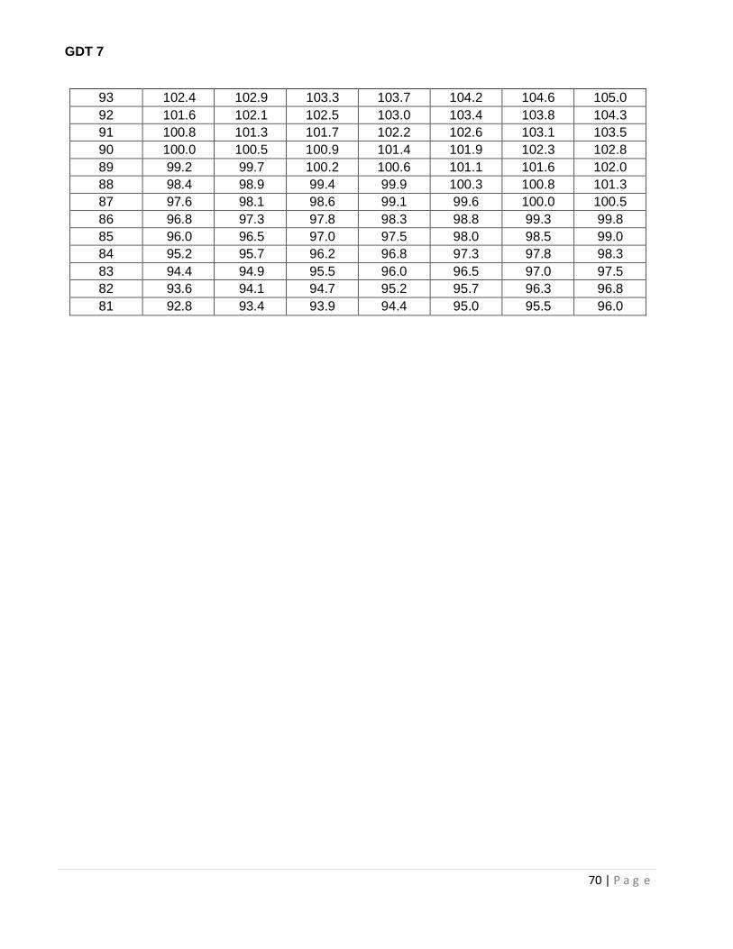
70 | P a g e
GDT 7
93 102.4 102.9 103.3 103.7 104.2 104.6 105.0
92 101.6 102.1 102.5 103.0 103.4 103.8 104.3
91 100.8 101.3 101.7 102.2 102.6 103.1 103.5
90 100.0 100.5 100.9 101.4 101.9 102.3 102.8
89 99.2 99.7 100.2 100.6 101.1 101.6 102.0
88 98.4 98.9 99.4 99.9 100.3 100.8 101.3
87 97.6 98.1 98.6 99.1 99.6 100.0 100.5
86 96.8 97.3 97.8 98.3 98.8 99.3 99.8
85 96.0 96.5 97.0 97.5 98.0 98.5 99.0
84 95.2 95.7 96.2 96.8 97.3 97.8 98.3
83 94.4 94.9 95.5 96.0 96.5 97.0 97.5
82 93.6 94.1 94.7 95.2 95.7 96.3 96.8
81 92.8 93.4 93.9 94.4 95.0 95.5 96.0

71 | P a g e
GDT 7
TABLE 5D FOR % PLUS NO. 10 IN TOTAL SAMPLE
% Plus No. 10 Material by Weight in Total Sample
-10
Density
29 30 31 32 33 34 35
130 132.8 132.9 133.0 133.1 133.2 133.3 133.4
129 132.1 132.2 132.3 132.4 132.5 132.6 132.7
128 131.4 131.5 131.6 131.7 131.8 131.9 132.1
127 130.6 130.8 130.9 131.0 131.1 131.3 131.4
126 129.9 130.0 130.2 130.3 130.4 130.6 130.7
125 129.1 129.3 129.4 129.6 129.7 129.8 130.0
124 128.4 128.6 128.7 128.9 129.0 129.2 129.3
123 127.7 127.8 128.0 128.2 128.3 128.5 128.6
122 126.9 127.1 127.3 127.4 127.6 127.8 128.0
121 126.2 126.3 126.5 126.7 126.9 127.1 127.2
120 125.4 125.6 125.8 126.0 126.2 126.4 126.5
119 124.7 124.9 125.1 125.3 125.5 125.7 125.9
118 123.9 124.2 124.4 124.6 124.8 125.0 125.2
117 123.2 123.4 123.6 123.8 124.1 124.3 124.5
116 122.5 122.7 122.9 123.1 123.4 123.6 123.8
115 121.7 122.0 122.2 122.4 122.7 122.9 123.1
114 121.0 121.2 121.5 121.7 122.0 122.2 122.4
113 120.3 120.5 120.8 121.0 121.3 121.5 121.8
112 119.5 119.8 120.0 120.3 120.5 120.8 121.1
111 118.8 119.0 119.3 119.6 119.8 120.1 120.4
110 118.0 118.3 118.6 118.9 119.1 119.4 119.7
109 117.3 117.6 117.9 118.2 118.4 118.7 119.0
108 116.6 116.9 117.1 117.4 117.7 118.0 118.3
107 115.8 116.1 116.4 116.7 117.0 117.3 117.6
106 115.1 115.4 115.7 116.0 116.3 116.6 117.0
105 114.3 114.7 115.0 115.3 115.6 115.9 116.3
104 113.6 113.9 114.3 114.6 114.9 115.3 115.6
103 112.9 113.2 113.5 113.9 114.2 114.6 114.9
102 112.1 112.5 112.8 113.2 113.5 113.9 114.2
101 111.4 111.7 112.1 112.5 112.8 113.2 113.5
100 110.6 111.0 111.4 111.7 112.1 112.5 112.8
99 109.9 110.3 110.7 111.0 111.4 111.8 112.2
98 109.2 109.6 109.9 110.3 110.7 111.1 111.5
97 108.4 408.8 109.2 109.6 110.0 110.4 110.8
96 107.7 108.1 108.5 108.9 109.3 109.7 110.1
95 106.9 107.3 107.7 108.2 108.6 109.0 109.4
94 106.2 106.6 107.0 107.4 107.9 108.3 108.7
93 105.4 105.9 106.3 106.7 107.2 107.6 108.0
92 104.7 105.1 105.6 106.0 106.5 106.9 107.3
91 104.0 104.4 104.9 105.3 105.8 106.2 106.6

72 | P a g e
GDT 7
90 103.2 103.7 104.1 104.6 105.0 105.5 106.0
89 102.5 103.0 103.4 103.9 104.3 104.8 105.3
88 101.7 102.2 102.7 103.2 103.6 104.1 104.6
87 101.0 101.5 102.0 102.5 102.9 103.4 103.9
86 100.3 100.8 101.3 101.7 102.2 102.7 103.2
85 99.5 100.0 100.5 101.0 101.5 102.0 102.5
84 98.8 99.3 99.8 100.3 100.8 101.3 101.9
83 98.1 98.6 99.1 99.6 100.1 100.6 101.2
82 97.3 97.8 98.4 98.9 99.4 100.0 100.5
81 96.6 97.1 97.6 98.2 98.7 99.3 99.8

73 | P a g e
GDT 7
TABLE 6D FOR % PLUS NO. 10 IN TOTAL SAMPLE
% Plus No. 10 Material by Weight in Total Sample
-10
Density
36 37 38 39 40 41 42
130 133.5 133.6 133.7 133.8 133.9 134.0 134.1
129 132.9 133.0 133.1 133.2 133.3 133.4 133.5
128 132.2 132.3 132.4 132.5 132.6 132.8 132.9
127 131.5 131.6 131.8 131.9 132.0 132.1 132.3
126 130.8 131.0 131.1 131.2 131.4 131.5 131.6
125 130.1 130.3 130.4 130.6 130.7 130.9 131.0
124 129.5 129.6 129.8 129.9 130.1 130.2 130.4
123 128.8 129.0 129.1 129.3 129.4 129.6 129.8
122 128.1 128.3 128.5 128.6 128.8 129.0 129.1
121 127.4 127.6 127.8 127.9 128.1 128.3 128.5
120 126.7 126.9 127.1 127.3 127.5 127.7 127.9
119 126.1 126.3 126.4 126.6 126.8 127.0 127.2
118 125.4 125.6 125.8 126.0 126.2 126.4 126.6
117 124.7 124.9 125.1 125.3 125.6 125.8 126.0
116 124.0 124.3 124.5 124.7 124.9 125.1 125.4
115 123.4 123.6 123.8 124.0 124.3 124.5 124.7
114 122.7 122.9 123.2 123.4 123.6 123.9 124.1
113 122.0 122.3 122.5 122.8 123.0 123.3 123.5
112 121.3 121.6 121.8 122.1 122.4 122.6 122.9
111 120.6 120.9 121.2 121.5 121.7 122.0 122.3
110 120.0 120.2 120.5 120.8 121.1 121.4 121.6
109 119.3 119.6 119.9 120.2 120.4 120.7 121.0
108 118.6 118.9 119.2 119.5 119.8 120.1 120.4
107 117.9 118.2 118.6 118.9 119.2 119.5 119.8
106 117.3 117.6 117.9 118.2 118.5 118.8 119.1
105 116.6 116.9 117.2 117.6 117.9 118.2 118.5
104 115.9 116.2 116.6 116.9 117.2 117.6 117.9
103 115.2 115.6 115.9 116.3 116.6 116.9 117.3
102 114.6 114.9 115.3 115.6 116.0 116.3 116.7
101 113.9 114.2 114.6 115.0 115.3 115.7 116.0
100 113.2 113.6 113.9 114.3 114.7 115.0 115.4
99 112.5 112.9 113.3 113.7 114.0 114.4 114.8
98 111.9 112.2 112.6 113.0 113.4 113.8 114.2
97 111.2 111.6 112.0 112.4 112.8 113.2 113.5
96 110.5 110.9 111.3 111.7 112.1 112.5 112.9
95 109.8 110.2 110.6 111.0 111.4 111.9 112.3
94 109.1 109.5 110.0 110.4 110.8 111.2 111.6
93 108.4 108.9 109.3 109.7 110.2 110.6 111.0
92 107.8 108.2 108.6 109.1 109.5 110.0 110.4
91 107.1 107.5 108.0 108.4 108.9 109.3 109.8

74 | P a g e
GDT 7
90 106.4 106.9 107.3 107.8 108.2 108.7 109.2
89 105.7 106.2 106.7 107.1 107.6 108.1 108.5
88 105.1 105.5 106.0 106.5 107.0 107.4 107.9
87 104.4 104.9 105.4 105.8 106.3 106.8 107.3
86 103.7 104.2 104.7 105.2 105.7 106.2 106.7
85 103.0 103.5 104.0 104.5 105.0 105.5 106.0
84 102.4 102.9 103.4 103.9 104.4 104.9 105.4
83 101.7 102.2 102.7 103.2 103.8 104.3 104.8
82 101.0 101.5 102.1 102.6 103.1 103.6 104.2
81 100.3 100.9 101.4 101.9 102.5 103.0 103.6

75 | P a g e
GDT 7
TABLE 7D FOR % PLUS NO 10 IN TOTAL SAMPLE
% PLUS NO 10 Material by Weight Total Sample
-10 Density 43 44 45
130 134.2 134.3 134.4
129 133.6 133.7 133.8
128 133.0 133.1 133.2
127 132.4 132.5 132.6
126 131.8 131.9 132.0
125 131.1 131.3 131.4
124 130.5 130.7 103.8
123 129.9 130.1 130.2
122 129.3 129.5 129.7
121 128.7 128.8 139.0
120 128.0 128.2 128.8
119 127.4 127.6 127.8
118 126.8 127.0 127.2
117 126.2 126.4 126.6
116 125.6 125.8 126.0
115 125.0 125.2 125.4
114 124.4 124.6 124.8
113 123.8 124.0 124.3
112 123.1 123.4 123.7
111 122.5 122.8 123.1
110 121.9 122.2 122.5
109 121.3 121.6 121.9
108 120.7 121.0 121.3
107 120.1 120.4 120.7
106 119.5 119.8 120.1
105 118.8 119.2 119.5
104 118.2 118.6 118.9
103 117.6 118.0 118.3
102 117.0 117.4 117.7
101 116.4 116.8 117.1
100 115.8 116.1 116.5
99 115.2 115.5 115.9
98 114.6 114.9 115.3
97 113.9 114.3 114.7
96 113.3 113.7 114.1
95 112.7 113.1 113.5
94 112.1 112.5 112.9
93 111.4 111.9 112.3
92 110.8 111.3 111.7
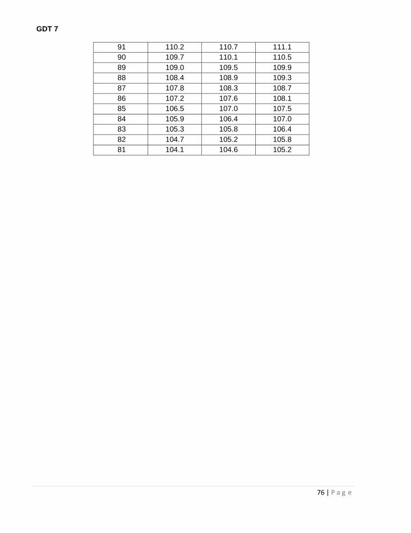
76 | P a g e
GDT 7
91 110.2 110.7 111.1
90 109.7 110.1 110.5
89 109.0 109.5 109.9
88 108.4 108.9 109.3
87 107.8 108.3 108.7
86 107.2 107.6 108.1
85 106.5 107.0 107.5
84 105.9 106.4 107.0
83 105.3 105.8 106.4
82 104.7 105.2 105.8
81 104.1 104.6 105.2
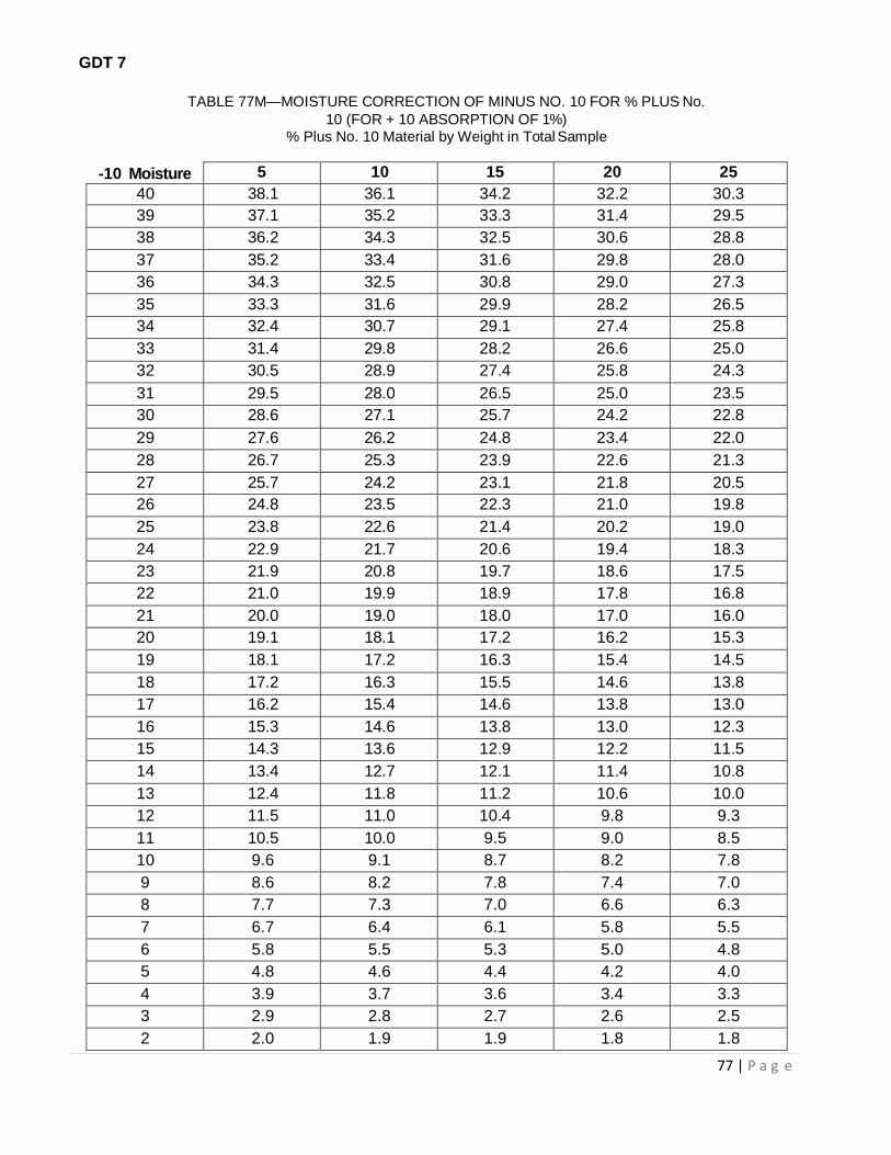
GDT 7
TABLE 77M—MOISTURE CORRECTION OF MINUS NO. 10 FOR % PLUS No.
10 (FOR + 10 ABSORPTION OF 1%) % Plus No. 10 Material by Weight in Total Sample
-10 Moisture 5 10 15 20 25
40 38.1 36.1 34.2 32.2 30.3
39 37.1 35.2 33.3 31.4 29.5
38 36.2 34.3 32.5 30.6 28.8
37 35.2 33.4 31.6 29.8 28.0
36 34.3 32.5 30.8 29.0 27.3
35 33.3 31.6 29.9 28.2 26.5
34 32.4 30.7 29.1 27.4 25.8
33 31.4 29.8 28.2 26.6 25.0
32 30.5 28.9 27.4 25.8 24.3
31 29.5 28.0 26.5 25.0 23.5
30 28.6 27.1 25.7 24.2 22.8
29 27.6 26.2 24.8 23.4 22.0
28 26.7 25.3 23.9 22.6 21.3
27 25.7 24.2 23.1 21.8 20.5
26 24.8 23.5 22.3 21.0 19.8
25 23.8 22.6 21.4 20.2 19.0
24 22.9 21.7 20.6 19.4 18.3
23 21.9 20.8 19.7 18.6 17.5
22 21.0 19.9 18.9 17.8 16.8
21 20.0 19.0 18.0 17.0 16.0
20 19.1 18.1 17.2 16.2 15.3
19 18.1 17.2 16.3 15.4 14.5
18 17.2 16.3 15.5 14.6 13.8
17 16.2 15.4 14.6 13.8 13.0
16 15.3 14.6 13.8 13.0 12.3
15 14.3 13.6 12.9 12.2 11.5
14 13.4 12.7 12.1 11.4 10.8
13 12.4 11.8 11.2 10.6 10.0
12 11.5 11.0 10.4 9.8 9.3
11 10.5 10.0 9.5 9.0 8.5
10 9.6 9.1 8.7 8.2 7.8
9 8.6 8.2 7.8 7.4 7.0
8 7.7 7.3 7.0 6.6 6.3
7 6.7 6.4 6.1 5.8 5.5
6 5.8 5.5 5.3 5.0 4.8
5 4.8 4.6 4.4 4.2 4.0
4 3.9 3.7 3.6 3.4 3.3
3 2.9 2.8 2.7 2.6 2.5
2 2.0 1.9 1.9 1.8 1.8
77 | P a g e
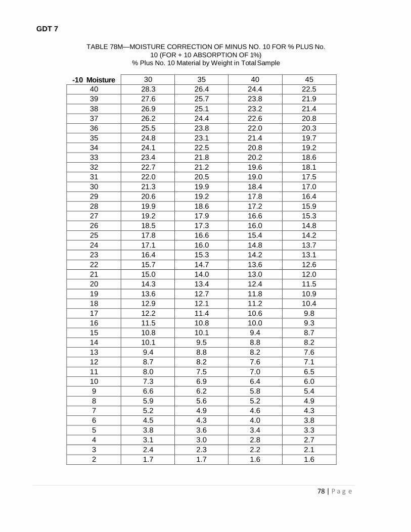
GDT 7
TABLE 78M—MOISTURE CORRECTION OF MINUS NO. 10 FOR % PLUS No.
10 (FOR + 10 ABSORPTION OF 1%) % Plus No. 10 Material by Weight in Total Sample
-10 Moisture 30 35 40 45
40 28.3 26.4 24.4 22.5
39 27.6 25.7 23.8 21.9
38 26.9 25.1 23.2 21.4
37 26.2 24.4 22.6 20.8
36 25.5 23.8 22.0 20.3
35 24.8 23.1 21.4 19.7
34 24.1 22.5 20.8 19.2
33 23.4 21.8 20.2 18.6
32 22.7 21.2 19.6 18.1
31 22.0 20.5 19.0 17.5
30 21.3 19.9 18.4 17.0
29 20.6 19.2 17.8 16.4
28 19.9 18.6 17.2 15.9
27 19.2 17.9 16.6 15.3
26 18.5 17.3 16.0 14.8
25 17.8 16.6 15.4 14.2
24 17.1 16.0 14.8 13.7
23 16.4 15.3 14.2 13.1
22 15.7 14.7 13.6 12.6
21 15.0 14.0 13.0 12.0
20 14.3 13.4 12.4 11.5
19 13.6 12.7 11.8 10.9
18 12.9 12.1 11.2 10.4
17 12.2 11.4 10.6 9.8
16 11.5 10.8 10.0 9.3
15 10.8 10.1 9.4 8.7
14 10.1 9.5 8.8 8.2
13 9.4 8.8 8.2 7.6
12 8.7 8.2 7.6 7.1
11 8.0 7.5 7.0 6.5
10 7.3 6.9 6.4 6.0
9 6.6 6.2 5.8 5.4
8 5.9 5.6 5.2 4.9
7 5.2 4.9 4.6 4.3
6 4.5 4.3 4.0 3.8
5 3.8 3.6 3.4 3.3
4 3.1 3.0 2.8 2.7
3 2.4 2.3 2.2 2.1
2 1.7 1.7 1.6 1.6
78 | P a g e

GDT 7
TABLE 3M—MOISTURE CORRECTION OF MINUS NO. 10 FOR % PLUS No. 10
(FOR + 10 ABSORPTION OF 2%) % Plus No. 10 Material by Weight in Total Sample
-10 Moisture 5 10 15 20 25
40 38.1 36.2 34.3 32.4 30.5
39 37.2 35.3 33.5 31.6 29.8
38 36.2 34.4 32.6 30.8 29.0
37 35.3 33.5 31.8 30.0 28.3
36 34.3 32.6 30.9 29.2 27.5
35 33.4 31.7 30.1 28.4 26.8
34 32.4 30.8 29.2 27.6 26.0
33 31.5 29.9 28.4 26.8 25.3
32 30.5 29.0 27.5 26.0 24.5
31 29.6 28.1 26.7 25.2 23.8
30 28.6 27.2 25.8 24.4 23.0
29 27.7 26.3 25.0 23.6 22.3
28 26.7 25.4 24.1 22.8 21.5
27 25.8 24.5 23.3 22.0 20.8
26 24.8 23.6 22.4 21.2 20.0
25 23.9 22.7 21.6 20.4 19.3
24 22.9 21.8 20.7 19.6 18.5
23 22.0 20.9 19.9 18.8 17.8
22 21.0 20.0 19.0 18.0 17.0
21 20.1 19.1 18.2 17.2 16.3
20 19.1 18.2 17.3 16.4 15.5
19 18.2 17.3 16.5 15.6 14.8
18 17.2 16.4 15.6 14.8 14.0
17 16.3 15.5 14.8 14.0 13.3
16 15.3 14.6 13.9 13.2 12.5
15 14.4 13.7 13.1 12.4 11.8
14 13.4 12.8 12.2 11.6 11.0
13 12.5 11.9 11.4 10.8 10.3
12 11.5 11.0 10.5 10.0 9.5
11 10.6 10.1 9.7 9.2 8.8
10 9.6 9.2 8.8 8.5 8.0
9 8.7 8.3 8.0 7.6 7.3
8 7.7 7.4 7.1 6.8 6.5
7 6.8 6.5 6.3 6.0 5.8
6 5.8 5.6 5.4 5.2 5.0
5 4.9 4.7 4.6 4.4 4.3
4 3.9 3.8 3.7 3.6 3.5
3 3.0 2.9 2.9 2.8 2.8
2 2.0 2.0 2.0 2.0 2.0
79 | P a g e
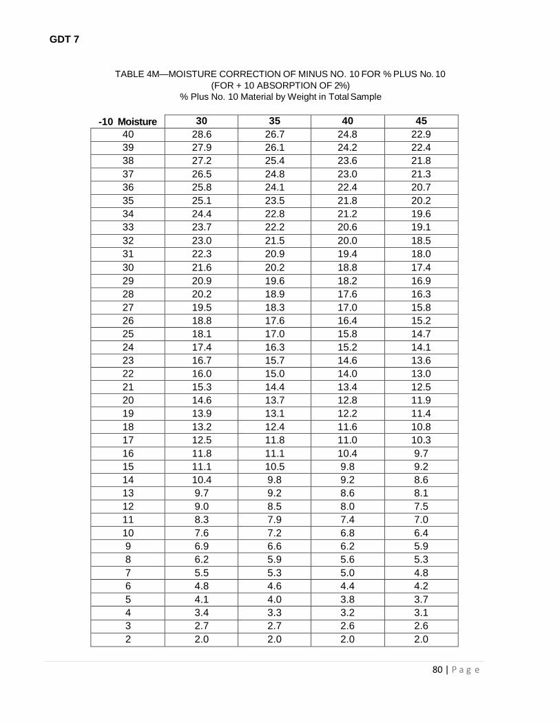
GDT 7
TABLE 4M—MOISTURE CORRECTION OF MINUS NO. 10 FOR % PLUS No. 10
(FOR + 10 ABSORPTION OF 2%)
% Plus No. 10 Material by Weight in Total Sample
-10 Moisture 30 35 40 45
40 28.6 26.7 24.8 22.9
39 27.9 26.1 24.2 22.4
38 27.2 25.4 23.6 21.8
37 26.5 24.8 23.0 21.3
36 25.8 24.1 22.4 20.7
35 25.1 23.5 21.8 20.2
34 24.4 22.8 21.2 19.6
33 23.7 22.2 20.6 19.1
32 23.0 21.5 20.0 18.5
31 22.3 20.9 19.4 18.0
30 21.6 20.2 18.8 17.4
29 20.9 19.6 18.2 16.9
28 20.2 18.9 17.6 16.3
27 19.5 18.3 17.0 15.8
26 18.8 17.6 16.4 15.2
25 18.1 17.0 15.8 14.7
24 17.4 16.3 15.2 14.1
23 16.7 15.7 14.6 13.6
22 16.0 15.0 14.0 13.0
21 15.3 14.4 13.4 12.5
20 14.6 13.7 12.8 11.9
19 13.9 13.1 12.2 11.4
18 13.2 12.4 11.6 10.8
17 12.5 11.8 11.0 10.3
16 11.8 11.1 10.4 9.7
15 11.1 10.5 9.8 9.2
14 10.4 9.8 9.2 8.6
13 9.7 9.2 8.6 8.1
12 9.0 8.5 8.0 7.5
11 8.3 7.9 7.4 7.0
10 7.6 7.2 6.8 6.4
9 6.9 6.6 6.2 5.9
8 6.2 5.9 5.6 5.3
7 5.5 5.3 5.0 4.8
6 4.8 4.6 4.4 4.2
5 4.1 4.0 3.8 3.7
4 3.4 3.3 3.2 3.1
3 2.7 2.7 2.6 2.6
2 2.0 2.0 2.0 2.0
80 | P a g e

GDT 7
TABLE 5M—MOISTURE CORRECTION OF MINUS NO. 10 FOR % PLUS No. 10
(FOR + 10 ABSORPTION OF 3%) % Plus No. 10 Material by Weight in Total Sample
-10 Moisture 5 10 15 20 25
40 38.2 36.3 34.5 32.6 30.8
39 37.2 35.4 33.6 31.8 30.0
38 36.3 34.5 32.8 31.0 29.3
37 35.3 33.6 31.9 30.2 28.5
36 34.4 32.7 31.1 29.4 27.8
35 33.4 31.8 30.2 28.6 27.0
34 32.5 30.9 29.4 27.8 26.3
33 31.5 30.0 28.5 27.0 25.5
32 30.6 29.1 27.7 26.2 24.8
31 29.6 28.2 26.8 25.4 24.0
30 28.7 27.3 26.0 24.6 23.3
29 27.7 26.4 25.1 23.8 22.5
28 26.8 25.5 24.3 23.0 21.8
27 25.8 24.6 23.4 22.2 21.0
26 24.9 23.7 22.6 21.4 20.3
25 23.9 22.8 21.7 20.6 19.5
24 23.0 21.9 20.9 19.8 18.8
23 22.0 21.0 20.0 19.0 18.0
22 21.1 20.1 19.2 18.2 17.3
21 20.1 19.2 18.3 17.4 16.5
20 19.2 18.3 17.5 16.6 15.8
19 18.2 17.4 16.6 15.8 15.0
18 17.3 16.5 15.8 15.0 14.3
17 16.3 15.6 14.9 14.2 13.5
16 15.4 14.7 14.1 13.4 12.8
15 14.4 13.8 13.2 12.6 12.0
14 13.5 12.9 12.4 11.8 11.3
13 12.5 12.0 11.5 11.0 10.5
12 11.6 11.1 10.7 10.2 9.8
11 10.6 10.2 9.8 9.4 9.0
10 9.7 9.3 9.0 8.6 8.3
9 8.7 8.4 8.1 7.8 7.5
8 7.8 7.5 7.3 7.0 6.8
7 6.8 6.6 6.4 6.2 6.0
6 5.9 5.7 5.6 5.4 5.3
5 4.9 4.8 4.7 4.6 4.5
4 4.0 3.9 3.9 3.8 3.8
3 3.0 3.0 3.0 3.0 3.0
2 2.1 2.1 2.2 2.2 2.3
81 | P a g e
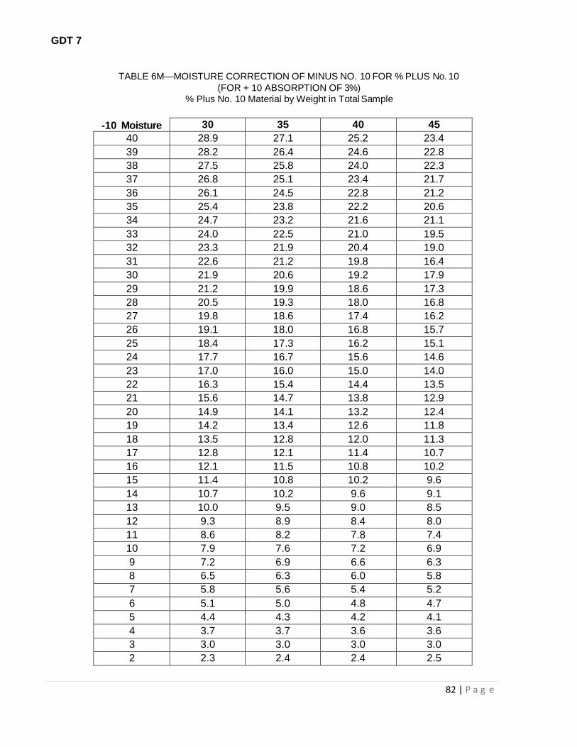
GDT 7
TABLE 6M—MOISTURE CORRECTION OF MINUS NO. 10 FOR % PLUS No. 10
(FOR + 10 ABSORPTION OF 3%) % Plus No. 10 Material by Weight in Total Sample
-10 Moisture 30 35 40 45
40 28.9 27.1 25.2 23.4
39 28.2 26.4 24.6 22.8
38 27.5 25.8 24.0 22.3
37 26.8 25.1 23.4 21.7
36 26.1 24.5 22.8 21.2
35 25.4 23.8 22.2 20.6
34 24.7 23.2 21.6 21.1
33 24.0 22.5 21.0 19.5
32 23.3 21.9 20.4 19.0
31 22.6 21.2 19.8 16.4
30 21.9 20.6 19.2 17.9
29 21.2 19.9 18.6 17.3
28 20.5 19.3 18.0 16.8
27 19.8 18.6 17.4 16.2
26 19.1 18.0 16.8 15.7
25 18.4 17.3 16.2 15.1
24 17.7 16.7 15.6 14.6
23 17.0 16.0 15.0 14.0
22 16.3 15.4 14.4 13.5
21 15.6 14.7 13.8 12.9
20 14.9 14.1 13.2 12.4
19 14.2 13.4 12.6 11.8
18 13.5 12.8 12.0 11.3
17 12.8 12.1 11.4 10.7
16 12.1 11.5 10.8 10.2
15 11.4 10.8 10.2 9.6
14 10.7 10.2 9.6 9.1
13 10.0 9.5 9.0 8.5
12 9.3 8.9 8.4 8.0
11 8.6 8.2 7.8 7.4
10 7.9 7.6 7.2 6.9
9 7.2 6.9 6.6 6.3
8 6.5 6.3 6.0 5.8
7 5.8 5.6 5.4 5.2
6 5.1 5.0 4.8 4.7
5 4.4 4.3 4.2 4.1
4 3.7 3.7 3.6 3.6
3 3.0 3.0 3.0 3.0
2 2.3 2.4 2.4 2.5
82 | P a g e

GDT 7
TABLE 7M—MOISTURE CORRECTION OF MINUS NO. 10 FOR % PLUS No. 10
(FOR + 10 ABSORPTION OF 4%) % Plus No. 10 Material by Weight in Total Sample
-10 Moisture 5 10 15 20 25
40 38.2 36.4 34.6 32.8 31.0
39 37.3 35.5 33.8 32.0 30.3
38 36.3 34.6 32.9 31.2 29.5
37 35.4 33.7 32.1 30.4 28.8
36 34.4 32.8 31.2 29.6 28.0
35 33.5 31.9 30.4 28.8 27.3
34 32.5 31.0 30.5 28.0 26.5
33 31.6 31.1 28.7 27.2 25.8
32 30.6 29.2 27.8 26.4 25.0
31 29.7 28.3 27.0 25.6 24.3
30 28.7 27.4 26.1 24.8 23.5
29 27.8 26.5 25.3 24.0 22.8
28 26.8 25.6 24.4 23.2 22.0
27 25.9 24.7 23.6 22.4 21.3
26 24.9 23.8 22.7 21.6 20.5
25 24.0 22.9 21.9 20.8 19.8
24 23.0 22.0 21.0 20.0 19.0
23 22.1 21.1 20.2 19.2 18.3
22 21.1 20.2 19.3 18.4 17.5
21 20.2 19.3 18.5 17.6 16.8
20 19.2 18.4 17.6 16.8 16.0
19 18.3 17.5 16.8 16.0 15.3
18 17.3 16.6 15.9 15.2 14.5
17 16.4 15.7 15.1 14.4 13.8
16 15.4 14.8 14.2 13.6 13.0
15 14.5 13.9 13.4 12.8 12.3
14 13.5 13.0 12.5 12.0 11.5
13 12.6 12.1 11.7 11.2 10.8
12 11.6 11.2 10.8 10.4 10.0
11 10.7 10.3 10.0 9.6 9.3
10 9.7 9.4 9.1 8.8 8.5
9 8.8 8.5 8.3 8.0 7.8
8 7.8 7.6 7.4 7.2 7.0
7 6.9 6.7 6.6 6.4 6.3
6 5.9 5.8 5.7 5.6 5.5
5 5.0 4.9 4.9 4.8 4.8
4 4.0 4.0 4.0 4.0 4.0
3 3.1 3.1 3.2 3.2 3.3
2 2.1 2.2 2.3 2.4 2.5
83 | P a g e

GDT 7
TABLE 8M—MOISTURE CORRECTION OF MINUS NO. 10 FOR % PLUS No. 10
(FOR + 10 ABSORPTION OF 4%)
% Plus No. 10 Material by Weight in Total Sample
-10 Moisture 30 35 40 45
40 29.2 27.4 25.6 23.8
39 28.5 26.8 25.0 23.3
38 27.8 26.1 24.4 22.7
37 27.1 25.5 23.8 22.2
36 26.4 24.8 23.2 21.6
35 25.7 25.4 22.6 21.1
34 25.0 23.5 22.0 20.5
33 24.3 22.9 21.4 20.0
32 23.6 22.2 20.8 19.4
31 22.9 21.6 20.2 18.9
30 22.2 20.9 20.6 18.3
29 21.5 20.3 19.0 17.8
28 20.8 19.6 18.4 17.2
27 20.1 19.0 17.8 16.7
26 19.4 18.3 17.2 16.1
25 18.7 17.7 16.6 15.6
24 18.0 17.0 16.0 15.0
23 17.3 16.4 15.4 14.5
22 16.0 15.7 14.8 13.9
21 15.9 15.1 14.2 13.4
20 15.2 14.4 13.6 12.8
19 14.5 13.8 13.0 12.3
18 13.8 13.1 12.4 11.7
17 13.1 12.5 11.8 11.2
16 12.4 11.8 11.2 10.6
15 11.7 11.2 10.6 10.1
14 11.0 10.5 10.0 9.5
13 10.3 9.9 9.4 9.0
12 9.6 9.2 8.8 8.4
11 8.9 8.6 8.2 7.9
10 8.2 7.9 7.6 7.3
9 7.5 7.3 7.0 6.8
8 6.8 6.6 6.4 6.2
7 6.1 6.0 5.8 5.7
6 5.4 5.3 5.2 5.1
5 4.7 4.7 4.6 4.6
4 4.0 4.0 4.0 4.0
3 3.3 3.4 3.4 3.5
2 2.6 2.7 2.8 2.9
84 | P a g e

85 | P a g e
GDT 7
TABLE 9M—MOISTURE CORRECTION OF MINUS NO. 10 FOR % PLUS No. 10
(FOR + 10 ABSORPTION OF 5%)
% Plus No. 10 Material by Weight in TotalSample
-10 Moisture 5 10 15 20 25
40 38.3 36.5 34.8 33.0 31.3
39 37.3 35.6 33.9 32.2 30.5
38 36.4 34.7 33.1 31.4 29.8
37 35.4 33.8 32.2 30.6 29.0
36 34.5 32.9 31.4 29.8 28.3
35 33.5 32.0 30.5 29.0 27.5
34 32.6 31.1 29.7 28.2 26.8
33 31.6 30.2 28.8 27.4 26.0
32 30.7 29.3 28.0 26.6 25.3
31 29.7 28.4 27.1 25.8 24.5
30 28.8 27.5 26.3 25.0 23.8
29 27.8 26.6 25.4 24.2 23.0
28 26.9 25.7 24.6 23.4 22.3
27 25.9 24.8 23.7 22.6 21.5
26 25.0 23.9 22.9 21.8 20.8
25 24.0 23.0 22.0 21.0 20.0
24 23.1 22.1 21.2 20.2 19.3
23 22.1 21.2 20.3 19.4 18.5
22 21.2 20.3 19.5 18.6 17.8
21 20.2 19.4 18.6 17.8 17.0
20 19.3 18.5 17.8 17.0 16.3
19 18.3 17.6 16.9 16.2 15.5
18 17.4 16.7 16.1 15.4 14.8
17 16.4 15.8 15.2 14.6 14.0
16 15.5 14.9 14.4 13.8 13.3
15 14.5 14.0 13.5 13.0 12.5
14 13.6 13.1 12.7 12.2 11.8
13 12.6 12.2 11.8 11.4 11.0
12 11.7 11.3 11.0 10.6 10.3
11 10.7 10.4 10.1 9.8 9.5
10 9.8 9.5 9.3 9.0 8.8
9 8.8 8.6 8.4 8.2 8.0
8 7.9 7.7 7.6 7.4 7.3
7 6.9 6.8 6.7 6.6 6.5
6 6.0 5.9 5.9 5.8 5.8
5 5.0 5.0 5.0 5.0 5.0
4 4.1 4.1 4.2 4.2 4.3
3 3.1 3.2 3.3 3.4 3.5
2 2.2 2.3 2.5 2.6 2.8

86 | P a g e
GDT 7
TABLE 10M—MOISTURE CORRECTION OF MINUS NO. 10 FOR % PLUS No.
10 (FOR + 10 ABSORPTION OF 5%)
% Plus No. 10 Material by Weight in Total Sample
-10 Moisture 30 35 40 45
40 29.5 27.8 26.0 24.3
39 28.8 27.1 25.4 23.7
38 28.1 26.5 24.8 23.2
37 27.4 25.8 24.2 22.6
36 26.7 25.2 23.6 22.1
35 26.0 24.5 23.0 21.5
34 25.3 23.9 22.4 21.0
33 24.6 23.2 21.8 20.4
32 23.9 22.6 21.2 19.9
31 23.2 21.9 20.6 19.3
30 22.5 21.3 20.0 18.8
29 21.8 20.6 19.4 18.2
28 21.1 20.0 18.8 17.7
27 20.4 19.3 18.2 17.1
26 19.7 18.7 17.6 16.6
25 19.0 18.0 17.0 16.0
24 18.3 17.4 16.4 15.5
23 17.6 16.7 15.8 14.9
22 16.9 16.1 15.2 14.4
21 16.2 15.4 14.6 13.8
20 15.5 14.8 14.0 13.3
19 14.8 14.1 13.4 12.7
18 14.1 13.5 12.8 12.2
17 13.4 12.8 12.2 11.6
16 12.7 12.2 11.6 11.1
15 12.0 11.5 11.0 10.5
14 11.3 10.9 10.4 10.0
13 10.6 10.2 9.8 9.4
12 9.9 9.6 9.2 8.9
11 9.2 8.9 8.6 8.3
10 8.5 8.3 8.0 7.8
9 7.8 7.6 7.4 7.2
8 7.1 7.0 6.8 6.7
7 6.4 6.3 6.2 6.1
6 5.7 5.7 5.6 5.6
5 5.0 5.0 5.0 5.0
4 4.3 4.4 4.4 4.5
3 3.6 3.7 3.8 3.9
2 2.9 3.1 3.2 3.4
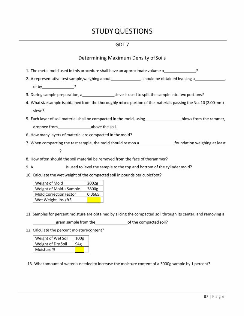
87 | P a g e
STUDY QUESTIONS
GDT 7
Determining Maximum Density of Soils
1. The metal mold used in this procedure shall have an approximate volume o ?
2. A representative test sample,weighing about , should be obtained byusing a ,
or by ?
3. During sample preparation, a sieve is used to split the sample into two portions?
4. What size sample is obtained from the thoroughly mixed portion of the materials passing the No. 10 (2.00 mm)
sieve?
5. Each layer of soil material shall be compacted in the mold, using blows from the rammer,
dropped from above the soil.
6. How many layers of material are compacted in the mold?
7. When compacting the test sample, the mold should rest on a foundation weighing at least
?
8. How often should the soil material be removed from the face of therammer?
9. A is used to level the sample to the top and bottom of the cylinder mold?
10. Calculate the wet weight of the compacted soil in pounds per cubic foot?
Weight of Mold 2002g
Weight of Mold + Sample 3800g Mold Correction Factor 0.0665
Wet Weight, lbs./ft3
11. Samples for percent moisture are obtained by slicing the compacted soil through its center, and removing a
gram sample from the of the compacted soil?
12. Calculate the percent moisture content?
Weight of Wet Soil 100g
Weight of Dry Soil 94g
Moisture %
13. What amount of water is needed to increase the moisture content of a 3000g sample by 1 percent?

14. Moisture content of the soil should be increased by, (1 percent to 2 percent for soils, 2
percent to 3 percent for soils).
15. Repeat procedure until the soil becomes and the of the compacted soil
substantially ?
16. Calculate the dry weight of the compacted soil in pounds per cubicfoot?
Wet Weight, lbs./ft3 119.6
Moisture % 6.4 Dry Weight, lbs./ft3
17. Plot the moisture density data points, draw a smooth curve connecting thepoints?
18. For purposes, interpret the maximum dry density as the highest density obtained in the test
series, and the optimum moisture as the moisture content at that respective density?
19. If the soil contains material retained on the No. 10 (2.00 mm) sieve and the show density
requirements on the total sample, you must correct the to reflect the percentage of Plus No.
10 (2.00 mm) material?
20. It is not necessary to correct the density for percentage of Plus No. 10 (2.00 mm) material when determining
maximum densities for compactioncontrol?
a) True
b) False
88 | P a g e
Dry Density % Moisture
100.0 6.0
104.8 8.0
108.0 10.0
104.0 12.0
Dry
Den
sity
Moisture Density Curve 110
108
106
104
102
100
98
0 2 4 6 8 10 12 14
% Moisture

89 | P a g e
21. Correct the maximum dry density and optimum moisture using the conversion factors in Tables 1D - 7D for
maximum dry density and Tables 1M - 10M for optimum moisture?
- No. 10 Maximum Dry Density 108.0
- No. 10 Maximum Optimum Moisture 10.0
% Plus No. 10 Material 20.0
Corrected Maximum Dry Density
Corrected Optimum Moisture

90 | P a g e
Performance Checklist
GDT 7
Determining Maximum Density of Soils
1. Dry the soil sample thoroughly in air or in the drying apparatus at a temperature not exceeding 60°C
[140°F].
2. Using a sampler, or by splitting or quartering, obtain a sample weighing approximately 10 lbs. (5 kg).
3. Record the sample mass and separate the sample into two portions using a No. 10 (2.00 mm) sieve.
4. Weigh and record the total mass of the sample.
5. Pulverize the sample in such a way as to avoid reducing the natural size of individual particles.
6. Separate the sample into two fractions using a 2.00-mm (No. 10) sieve.
7. Pulverize the material retained on the sieve until the aggregations of soil particles are broken into separate
grains.
8. Re-sieve the ground soil on the 2.00-mm (No. 10) sieve.
9. Weigh and record the mass of material retained the 2.00-mm (No. 10) sieve.
10. Transfer the material passing the 2.00-mm (No. 10) sieve into a large pan or onto a suitable cloth and mix it
thoroughly.
11. Using a sampler, or by splitting or quartering, obtain a sample with a mass of 6.6 lb (3000 g).
12. Compact the test sample in the mold assembly in three equal layers.
▪ Compact each layer with 25 blows from the rammer dropped from 1 ft (304.8 mm) above the soil.
▪ Rest the mold on a uniform, rigid foundation, such as a concrete block weighing at least 200 lbs (90 kg).
▪ Uniformly distribute the blows over the surface of the compacted layer.
▪ Remove the soil thatadheres to the face of the rammer after every 25th blow.
13. After compacting, remove the extension and base plate.
14. Carefully level the compacted soil to the top and bottom of the cylinder with thestraightedge.
15. Weigh the cylinder and sample together.
16. Remove the compacted soil from the cylinder and slice it vertically through its center.
17. Take a 100 g sample from the center and weigh it immediately.
18. Dry the sample to a constant mass.
19. Thoroughly pulverize the remaining material from the compacted sample.
20. Add enough water to increase the moisture content of the soil in predeterminedincrements.
21. Repeat steps 12 through 18 until the soil becomes very wet and the wet weight of the compacted soil sub-
stantially decreases.

91 | P a g e
22. Repeat the procedure until the soil becomes very wet and the wet weight of the compacted soil substan-
tially decreases.

92 | P a g e
SECTION 8
GDT 49
Determining the Theoretical Maximum of Dry Density of Materials containing > 25% re- tained on the no. 10 sieve using a 10-pound rammer and an 18-inchdrop

93 | P a g e
GDT 49
A. Scope
For a complete list of GDTs, please see the Table of Contents.
Use this method to determine the theoretical maximum dry density and optimum moisture of soil aggregate mixtures
when the material contains more than 25 percent retained on the No. 10 (2 .00 mm) sieve.
B. Apparatus
The apparatus consists of the following:
1. Mold: Use a cylindrical metal mold approximately 6 in (152.4 mm) diameter and 6 in (152.4 mm) high. This moldis
fitted with a detachable base plate and a removable extension approximately 2.5 in (63.5 mm) high (WM-06).
2. Rammer: Use a metal rammer with a 2-in (50 mm) diameter and a flat circular face and that weighs 10 lbs(4.536
kg). The rammer must be able to control the height of drop to a free fall of 18 inches above the soil(WR-1-1).
3. Scales and Balances: Use a scale with at least a 75 to 100 lbs (34 to 46.36 kg) capacity, sensitive to and graduated in
0.1 lbs (0.045 kg), and a 10 lbs (4.5 kg) capacity balance sensitive to 0.001 lb (0.5 g).
4. Drying Device: Use a stove or oven capable of rapidly drying the moisture determination sample.
5. Straightedge: Use a steel bar at least 12 in (304.8 mm) long (WS-13-1).
6. Pans or Dishes: Use pie pans or evaporating dishes suitable for drying soil samples (WD-3).
7. Glass Graduate: Use a glass (Bit-04-100) or plastic (WC-P100) graduate of 3.4 oz (100 ml) capacity used for
measuring the mixing water.
8. Container: Use a suitable container for immersing the coarseaggregate.
C. Sample Size and Preparation 1. Ensure that the material meets the graduation requirements of GDT 7.
2. Dry a sample weighing approximately 50 lbs (22.68 kg) until it is friable. Dry the sample in open air or with a drying
apparatus that does not cause the material to exceed 140 °F (60 °C).
3. Break up any aggregations to pass through the 3/4 in (19 mm) sieve without reducing the natural size of the
individual particles.
4. Grade the material over the 3/4 in (19 mm) sieve.
5. Weigh the amount retained and discard it.
6. Replace the material retained on the 3/4 in (19 mm) sieve with an equal weight of material retained on the No. 4
(4.75 mm) sieve. Take the replacement material from a remaining portion of the material beingtested.
7. Select a representative sample weighing approximately 25 lbs (11.34 kg).
D. Procedures 1. Thoroughly mix the selected representative sample with enough water to dampen it approximately 3 percent below
optimum moisture content.
2. Form a specimen by compacting the prepared material in the 6 in (152.4 mm) mold (with collar attached).
a. Compact the material in five equal layers so the total compacted depth is about 5 in (127mm).
b. Compact each layer with 56 uniformly distributed blows from therammer.
3. After compacting the five layers, remove the collar.
4. Carefully trim the compacted material with the straightedge to be even with the top and bottom of the mold.
5. Weigh the mold and moist material.

94 | P a g e
GDT 49
6. Calculate and record the wet weight in lbs/ft³ (kg/m³) as follows:
Wet weight = (weight of compacted specimen and mold – weight of the mold) x (13.33).
7. Remove the material from the mold and slice it vertically through thecenter.
8. Take a representative sample of the material, weighing at least 1 lbs (500 g), and weigh it immediately.
9. Dry the sample at 230 ° ± 9 °F (110 ° ± 5 °C) in theoven.
10. Thoroughly break up the remainder of the compacted material until it will pass a 3/4 in (19mm) sieve.
11. Add this material to the original portion of the sample that passed the 3/4 in (19 mm) sieve and was not usedbefore.
12. Add enough water to increase the moisture content of the sample by about 1 percent.
13. Repeat Procedures, steps 2 through 12 until there is either a decrease or no change in the wet weight/ft³ (m³) of the
compacted material.
E. Calculations 1. Calculate the moisture content and the dryweight of the material as compacted for each trial, as follows:
A - B
M = x 100
B
and,
where:
W1
W = x 100
M + 100
M = Percentage of moisture in the specimen
A = Weight of the wet material
B = Weight of the dry material
W = Dry weight, in lbs per ft³ (kg per m³), of compacted material
W1 = Wet weight, in lbs per ft³ (kg per m³), of compacted material
2. Plot the dry weights as ordinates and the corresponding moisture contents as abscissas.
3. Draw a smooth curve through the resulting points.
4. Read the results from the curve. The peak of the curve corresponds to the optimum moisture content and the
theoretical maximum drydensity.
F. Report Report the optimum moisture content and the theoretical maximum dry density on Form 495.
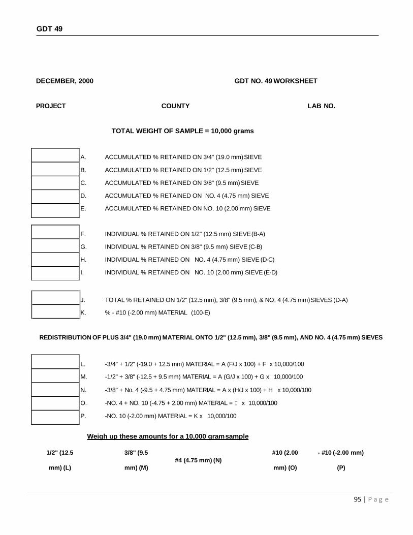
95 | P a g e
GDT 49
DECEMBER, 2000 GDT NO. 49 WORKSHEET
PROJECT COUNTY LAB NO.
TOTAL WEIGHT OF SAMPLE = 10,000 grams
A. ACCUMULATED % RETAINED ON 3/4" (19.0 mm) SIEVE
B. ACCUMULATED % RETAINED ON 1/2" (12.5 mm) SIEVE
C. ACCUMULATED % RETAINED ON 3/8" (9.5 mm) SIEVE
D. ACCUMULATED % RETAINED ON NO. 4 (4.75 mm) SIEVE
E. ACCUMULATED % RETAINED ON NO. 10 (2.00 mm) SIEVE
F. INDIVIDUAL % RETAINED ON 1/2" (12.5 mm) SIEVE (B-A)
G. INDIVIDUAL % RETAINED ON 3/8" (9.5 mm) SIEVE (C-B)
H. INDIVIDUAL % RETAINED ON NO. 4 (4.75 mm) SIEVE (D-C)
I. INDIVIDUAL % RETAINED ON NO. 10 (2.00 mm) SIEVE (E-D)
J. TOTAL % RETAINED ON 1/2" (12.5 mm), 3/8" (9.5 mm), & NO. 4 (4.75 mm) SIEVES (D-A)
K. % - #10 (-2.00 mm) MATERIAL (100-E)
REDISTRIBUTION OF PLUS 3/4" (19.0 mm) MATERIAL ONTO 1/2" (12.5 mm), 3/8" (9.5 mm), AND NO. 4 (4.75 mm) SIEVES
L. -3/4" + 1/2" (-19.0 + 12.5 mm) MATERIAL = A (F/J x 100) + F x 10,000/100
M. -1/2" + 3/8" (-12.5 + 9.5 mm) MATERIAL = A (G/J x 100) + G x 10,000/100
N. -3/8" + No. 4 (-9.5 + 4.75 mm) MATERIAL = A x (H/J x 100) + H x 10,000/100
O. -NO. 4 + NO. 10 (-4.75 + 2.00 mm) MATERIAL = I x 10,000/100
P. -NO. 10 (-2.00 mm) MATERIAL = K x 10,000/100
Weigh up these amounts for a 10,000 gram sample
1/2" (12.5 3/8" (9.5 #10 (2.00 - #10 (-2.00 mm)
#4 (4.75 mm) (N)
mm) (L) mm) (M) mm) (O) (P)

96 | P a g e
GDT 49
CUMULATIVE WEIGHT
EXAMPLE
DECEMBER, 2000 GDT NO. 49 WORKSHEET
PROJECT COUNTY LAB NO.
TOTAL WEIGHT OF SAMPLE = 10,000 grams
A. ACCUMULATED % RETAINED ON 3/4" (19 mm) SIEVE
B. ACCUMULATED % RETAINED ON 1/2" (12.5 mm) SIEVE
C. ACCUMULATED % RETAINED ON 3/8" (9.5 mm) SIEVE
D. ACCUMULATED % RETAINED ON NO. 4 (4.75 mm) SIEVE
E. ACCUMULATED % RETAINED ON NO. 10 (2.00 mm) SIEVE
F. INDIVIDUAL % RETAINED ON 1/2" (12.5 mm) SIEVE (B-A)
G. INDIVIDUAL % RETAINED ON 3/8" (9.5 mm) SIEVE (C-B)
H. INDIVIDUAL % RETAINED ON NO. 4 (4.75 mm) SIEVE (D-C)
I. INDIVIDUAL % RETAINED ON NO. 10 (2.00 mm) SIEVE (E-D)
J. TOTAL % RETAINED ON 1/2" (12.5 mm), 3/8" (9.5 mm), & NO. 4 (4.75 mm) SIEVES (D-A)
K. % - #10 (-2.00 mm) MATERIAL (100-E)
REDISTRIBUTION OF PLUS 3/4" (19 mm) MATERIAL ONTO 1/2" (12.5 mm), 3/8" (9.5 mm), AND NO. 4 (4.74 mm) SIEVES
L. -3/4" + 1/2" (-19 + 12.5 mm) MATERIAL = A (F/J x 100) + F x 10,000/100
M. -1/2" + 3/8" (-12.5 mm + 9.5 mm) MATERIAL = A (G/J x 100) + G x 10,000/100
N. -3/8" + No. 4 (-9.5 mm + 4.75 mm) MATERIAL = A x (H/J x 100) + H x 10,000/100
O. -NO. 4 + NO. 10 (-4.75 mm + 2.00 mm) MATERIAL = I x 10,000/100
P. -NO. 10 (-2.00 mm) MATERIAL = K x 10,000/100
Weigh up these amounts for a 10,000 gram sample
1/2" (12.5 3/8" (9.5 #4 (4.75 mm) #10 (2.00
34
41
14.0
25.0
32.0
48.0
59.0
11
7
16
11
1553
988
2259
1100
4100

97 | P a g e
mm) (L) mm) (M) (N) mm)(O)
1553 988
2259
1100
4100
2541
4800
5900
10000
CUMULATIVE WEIGHT

98 | P a g e

99 | P a g e

100 | P a g e
STUDY QUESTIONS
GDT 49
Determine the Theoretical Maximum Dry Density and Optimum Moisture of Soil Aggregate
Mixtures
1. The mold in this procedure will have an approximate diameter of and height of .
2. The metal rammer will have a diameter of and a weight of . The rammer will be
dropped at a height of from the surface the .
3. What size sample is taken and dried in a drying apparatus at a temperature not to exceed what temperature?
,
4. Any material larger than the shall be discarded and replaced with material retained on the
sieve.
5. A representative sample of approximately is needed to perform the test.
6. What should the initial moisture content of the sample be mixedto?
7. Each moisture content shall be compacted with in layers?
8. After the mold has been compacted, the collar is removed, and the compacted material timedwhere?
a) at the top of the mold
b) bottom of the mold
c) Both top and bottom

101 | P a g e
Moisture Density Curve 148
147.5
147
146.5
146
145.5
145
4 4.5 5 5.5
% Moisture
6 6.5 7
9. Calculate the wet weight of the compacted soil in pounds per cubic foot?
Weight of Mold 5920g Weight of Mold + Sample 11245g
Mold Correction Factor 0.02950
Wet Weight, lbs./ft3
10. Samples for percent moisture are obtained by slicing the compacted soil through its center, and removing a
gram sample from the of the compacted material?
11. Calculate the percent moisture content?
Weight of Wet Soil 500g Weight of Dry Soil 472.8g
Moisture %
12. Moisture samples will be dried in an oven capable of maintain whattemperature?
13. Moisture will be increased at a rate of approximately and material compacted until a -
.
14. Plot the moisture density data points,draw a smooth curve connecting the points?
Dry Density % Moisture
145.5 5.1
146.5 5.3
147.8 5.9
146.4 6.7
Dry
De
nsit
y

102 | P a g e
15. The theoretical maximum dry density and optimum moisture will be measured from?
a) Highest plotted density
b) the plotted density after decline
c) Highest moisture content
d) the peak of the curve

103 | P a g e
Performance Checklist
GDT 49
Determine the Theoretical Maximum Dry Density and Optimum Moisture of Soil Aggregate
Mixtures
1. Dry approximately 50lbs not exceeding 140 degrees F until is friable?
2. Break up any aggregations to pass through the 3/4 in (19 mm) sieve without reducing the natural size of the individ-
ual particles?
3. Grade over 3/4"sieve and weigh amount retained and discard?
4. Replace the material retained on the 3/4 in (19 mm) sieve with an equal weight of material from a remaining
portion of the material retained on the No. 4 sieve?
5. Select a representative sample weighing approximately 25 lbs (11.34 kg)?
6. Thoroughly mix the selected representative sample with enough water to dampen it approximately 3 percent below
optimum moisture content?
7. Form a specimen by compacting the prepared material in the 6 in (152.4mm) diameter, 6 in (152.4 mm) high mold
(with collar attached)?
8. Compact the material in five equal layers so the total compacted depth is about 5 in (127 mm)?
9. Compact each layer with 56 uniformly distributed blows from therammer?
10. After compacting the five layers, remove the collar and carefully trim the compacted material with the straight-
edge to be even with the top and bottom of the mold?
11. Weigh the mold and moist material?
12. Calculate and record the wet weight in lbs/ft³ (kg/m³) as follows:
Wet weight = (weight of compacted specimen and mold – weight of the mold) x (13.33).
13. Remove the material from the mold and slice it vertically through the center?
14. Take a representative sample of the material, weighing at least 1 lbs (500 g), and weigh it immediately?

104 | P a g e
15. Dry the sample at 230 ° ± 9 °F (110 ° ± 5 °C) in the oven?
16. Thoroughly break up the remainder of the compacted material until it will pass a 3/4 in (19 mm) sieve?
17. Add this material to the original portion of the sample that passed the 3/4 in (19 mm) sieve and was not used
before?
18. Add enough water to increase the moisture content of the sample by about 1percent?
19. Repeat Procedures, steps 7 through 18 until there is either a decrease or no change in the wet weight/ft³ (m³) of
the compacted material?
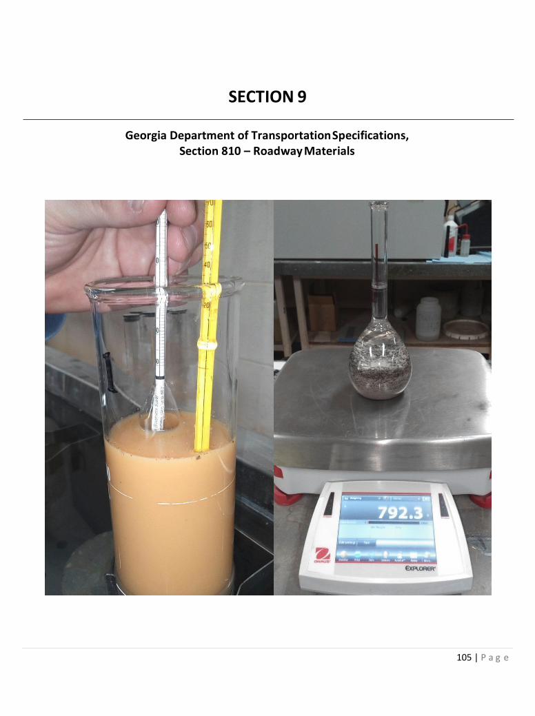
105 | P a g e
SECTION 9
Georgia Department of Transportation Specifications, Section 810 – Roadway Materials

106 | P a g e
Section 810—Roadway Materials
810.1 General Description
This section includes the requirements for the materials used in roadway construction.
810.1.1 Related References
A. Standard Specifications
General Provisions 101 through 150.
B. Referenced Documents
GDT 4
GDT 6
GDT 7
GDT 67
810.2 Materials
810.2.1 Roadway Materials
A. Requirements
Do not use materials containing logs, stumps, sod, weeds, or other perishable matter.
1. Classes
The materials are divided into six major classes. Classes I, II, and III are further subdivided and identified by description
and physical property requirements specified in the table below and in Table 1. Classes IV, V, and VI are identified by
descriptive requirements.
Class I
IA1 and IA2 Medium- to well-graded sand or clayey sand.
IA3 Fine-grained, silty, or clayey sand; usually less dense than IA1 or IA2.
These soils have an excellent bearing capacity.
Class II
IIB1, IIB2, and IIB3
Medium- to well-graded sandy clays, sandy silts, and clays with some mica.
These soils generally have low volume change properties and good densities that serve well as subgrade material.
IIB4 Similar to IIB1, IIB2, and IIB3, but generally contain more mica and are more sensitive to moisture. The bearing value of these soils is less predictable.
The soils may or may not be satisfactory for subgrade material. Analyze file data or
run laboratory and/or field tests for Class IIB4 when considering it for a subgrade material.
Class III
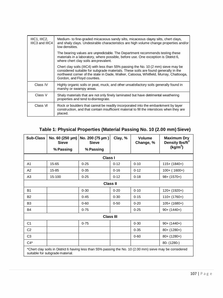
107 | P a g e
IIIC1, IIIC2, IIIC3 and IIIC4
Medium- to fine-graded micaceous sandy silts, micaceous clayey silts, chert clays, and shaly clays. Undesirable characteristics are high volume change properties and/or low densities.
The bearing values are unpredictable. The Department recommends testing these materials in a laboratory, where possible, before use. One exception is District 6, where chert clay soils are prevalent.
Chert clay soils (IIIC4) with less than 55% passing the No. 10 (2 mm) sieve may be considered suitable for subgrade materials. These soils are found generally in the northwest corner of the state in Dade, Walker, Catoosa, Whitfield, Murray, Chattooga, Gordon, and Floyd counties.
Class IV Highly organic soils or peat, muck, and other unsatisfactory soils generally found in marshy or swampy areas.
Class V Shaly materials that are not only finely laminated but have detrimental weathering properties and tend to disintegrate.
Class VI Rock or boulders that cannot be readily incorporated into the embankment by layer construction, and that contain insufficient material to fill the interstices when they are placed.
Table 1: Physical Properties (Material Passing No. 10 (2.00 mm) Sieve)
Sub-Class No. 60 (250 µm)
Sieve
% Passing
No. 200 (75 µm )
Sieve
% Passing
Clay, % Volume Change, %
Maximum Dry
Density lbs/ft3
(kg/m3)
Class I
A1 15-65 0-25 0-12 0-10 115+ (1840+)
A2 15-85 0-35 0-16 0-12 100+ ( 1600+)
A3 15-100 0-25 0-12 0-18 98+ (1570+)
Class II
B1 0-30 0-20 0-10 120+ (1920+)
B2 0-45 0-30 0-15 110+ (1760+)
B3 0-60 0-50 0-20 105+ (1680+)
B4 0-75 0-25 90+ (1440+)
Class III
C1 0-75 0-30 90+ (1440+)
C2 0-35 80+ (1280+)
C3 0-60 80+ (1280+)
C4* 80- (1280-)
*Chert clay soils in District 6 having less than 55% passing the No. 10 (2.00 mm) sieve may be considered suitable for subgrade material.

108 | P a g e
B. Fabrication
General Provisions 101 through 150.
C. Acceptance
Test as follows:
Test Method
Soil gradation GDT 4
Volume change GDT 6
Maximum density GDT 7 or GDT 67
D. Materials Warranty
General Provisions 101 through 150.

109 | P a g e
STUDY QUESTIONS
Georgia Department of Transportation Specifications, Section 810 – Roadway Materials
1. Roadway materials are divided into major classes?
2. What classes are identified by descriptive requirements?
3. Materials containing logs, stumps, sod, weeds, or other perishable matter are acceptable?
a) True
b) False
4. Physical properties for class I, II, and III soils, are determined on the materials passing the
sieve.
5. Materials with physical properties meeting sub-class IIB3 requirements, would serve well as subgrade material?
a) True
b) False
6. Using the physical properties, determine the material sub-class?
% Passing No. 40 20
% Passing No. 60 32
% Passing No. 200 48
% Clay 50
% Volume Change 12
Maximum Dry Density lbs/ft3 103
Classification

110 | P a g e
SECTION 10
Georgia Department of Transportation Specifications, Section 814 – Soil Base Materials

111 | P a g e
Section 814—Soil Base Materials
814.1 General Description
This section includes the requirements for soil base materials, including topsoil or sand-clay, soil-cement, sand for bituminous sta-
bilization, and chert.
814.1.1 Related References
A. Standard Specifications
Section 209– Subgrade Construction Sec-
tion 301– Soil-Cement Construction Sec-
tion 800–Coarse Aggregate
Section 810–Roadway Materials
Section 831–Admixtures
B. Referenced Documents
AASHTO T 89 AASHTO
T 90
ASTM D 516
GDT 4
GDT 6
GDT 7
GDT 65
GDT 67
GDT 98
814.2 Materials
814.2.1 Topsoil or Sand-Clay
A. Requirements
1. Use topsoil or sand-clay that is a natural or artificial mixture of clay or soil binder with sand or other aggregate. Do
not use a mixture that contains substances detrimental to the material.
Obtain the materials from sources approved bythe Engineer.
Ensure that the aggregate retained on No. 10 (2 mm ) sieve (coarse aggregate) is of hard, durable particles.
2. Sand and Binder
Use hard, sharp, durable, siliceous particles. Use binder made from qualityclay.
3. Oversize
Remove particles with diameters greater than 2 in (50 mm) before depositing the topsoil or sand-clay on the road.
Remove particles with screens or grizzlies, or by hand if few oversized pieces exist. You maycrush the oversized pieces

112 | P a g e
and use them.
4. Topsoil
Use a topsoil that is a natural, generally pebbly material occurring in shallow surface deposits on usually elevated areas.
5. Natural Sand-Clay
Use a natural sand-clay that is a mixture of natural material, largely sand and clay in proper proportions, occurring in de-
posits of considerable depth.
6. Artificial Sand-Clay
Use an artificial sand-clay that is largely a mixture of artificial sand and clay. You may make the mixture by combining
clay or soil binder and sand or aggregate inthe proper proportions.
7. Topsoil and Sand-Clay
Use topsoil and sand- clay with the following properties:
Sieve Size Amount
Passing 2 in (50 mm) 100% by weight
Passing 1-1/2 in (37.5 mm) 80-100% by weight
8. Ensure that material passing the No. 10 (2 mm) sieve meets the following requirements:
Sieve Size Percent Passing by Weight
Passing No. 10 (2 mm) sieve 100
Passing No. 60 (250 µm) sieve 15-85
Passing No. 200 (75 µm) sieve 9-35
Clay 9-25
Volume change, max. percent 12
Maximum density, lb/ft³ (kg/m³) 110+ (1760+)
B. Fabrication
General Provisions 101 through 150.
C. Acceptance
The Department or Producer will test asfollows:
Test Method
Soil gradation GDT 4
Volume change GDT 6
Maximum density GDT 7 or GDT 67
Liquid Limit AASHTO T 89
Plastic Limit and Plasticity Index AASHTO T 90
Passing No. 40 (425 µm) Liquid Limit (LL) of 25 or less
Plasticity Index (PI) of 9 or less

113 | P a g e
D. Materials Warranty
General Provisions 101 through 150.
814.2.2 Soil-Cement Material
A. Requirements
1. Ensure that the material for soil-cement base will:
a. Meet the requirements of Subsection 810.2.01 for Classes IA1, IA2, IA3, or IIB1 with thefollowing
modifications:
Clay content 5 to 25%
Volume change 18% maximum
Liquid Limit 25% maximum
Plasticity Index 10% maximum
Maximum dry density 95 lb/ft³ (1520 kg/m³) minimum
Sulfates 4000 ppm maximum
pH 4.0 minimum
b. Be friable and not contain large amounts of heavy or plastic clay lumps, organic material, roots, or other sub-
stances that would interfere with how the Portland cement sets, plant production, or the finished surface of the
base and meet the requirements of Subsection 301.3.05.A.2, “Pulverization” or Subsection 301.3.05.B.1, “Soil”.
c. Produce a laboratory unconfined compressive strength of at least 450 psi (3.1 MPa). To make the sample, mix in a
minimum of 5% to a maximum of 9 percent Type I Portland cement, moist-cure for 7 days, and test with GDT 65.
2. Analyze the soil-cement design and create a Job Mix Formula for each Project where soil-cement base or subbase is
specified. Have the Job Mix Formula approved by the Engineer before starting base or subbaseconstruction.
3. You may use fly ash or slag that meets the requirements of Subsection 831.2.03 as admixtures for poorly reacting
soils when the blend of soil and fly ash, or slag, meets the design requirements in this Subsection.
4. Ensure that subgrade material used underneath the soil-cement base meets the sulfate and pH requirements of this
subsection (See Subsection 209.3.05.A.7).
B. Fabrication
General Provisions 101 through 150.
C. Acceptance
Test as follows:
Test Method
Soil gradation GDT 4
Volume Change GDT 6
Maximum density GDT 7 or GDT 67
Soil-Cement Design GDT 65
pH GDT 98
Sulfates ASTM D 516

114 | P a g e
Liquid Limit AASHTO T 89
Plastic Limit and Plasticity Index AASHTO T 90
D. Materials Warranty
General Provisions 101 through 150.

115 | P a g e
STUDY QUESTIONS
Georgia Department of Transportation Specifications, Section 814 – Soil Base Materials
1. Subgrade material used underneath soil-cement base shall be tested for sulfate and pH?
a) True
b) False
2. For materials used as sand-clay base, the materials passing the sieve shall have a
of 9 or less?
3. Particles with diameters greater than shall be removed before depositing topsoil or
sand-clay on the road?
4. Laboratory specimens for a soil-cement mix design should becured for days and should
produce an unconfined compressive strength of at least psi ( MPa)?
5. Soils meeting classes are suitable for use as soil-cement material?
a) True
b) False
6. Materials passing the No. 10 sieve, used in sand-clay base, shall have a maximum dry densityof
lbs/ft³?
7. What test method is required to perform PH testing for materials used in soil-cement base construc-
tion?
a) GDT 98
b) GDT 6
c) T 96
d) None of the above

116 | P a g e
SECTION 11
Georgia Department of Transportation Appendix
117 | P a g e
Appendix A
Answers to Study Questions
Section 1
AASHTO R 58, Standard Practice for Dry Preparation of
Disturbed Soil and Soil-Aggregate Samples for Test
1. This method describes the dry preparation of soil and soil–aggregate samples?
2. A revolving drum, into which the soil sample and rubber-covered rollers are placed, is a suitable pulverizing
device?
a) True
b) False
3. For the particle size analysis-T88, material passing a 2.00-mm (No. 10) sieve is required in amounts equal to
approximately, 110 g for sandy soils and approximately 60 g for silty or clayeysoils.
4. What is the minimum amount required, of material passing the 0.425-mm (No. 40) sieve, for performing physi-
cal testing? 300g
5. Samples should be dried at a temperature not exceeding 60°C[140°F]?
6. Representative test samples of the amount required to perform the desired tests shall be taken with a sam-
pler, or by splitting or quartering.
7. Samples dried in an oven or other drying apparatus at a temperature not exceeding 60°C [140°F] are consid-
ered to be air dried?
a) True
b) False
8. List the two alternate methods used to separate fraction sizes of the portion of the dried sample selected for
particle-sized analysis and physical tests? Alternate Methods Using 2.00-mm (No. 10) Sieve, Alternate Method
Using 4.75-mm and 2.00-mm (Nos. 4 and 10) Sieves

118 | P a g e
9. Fractions retained on the 4.75-mm (No. 4) sieve and the 2.00-mm (No. 10) sieve are not included in the sieve
analysis and should be discarded?
a) True
b) false
10. What is the required sample mass of material passing the 2.00-mm (No. 10) sieve, for specific gravity, when
the volumetric flask is to be used? 25g
11. Physical tests are performed on materials passing the 0.425-mm (No. 40) sieve?
Section 2
AASHTO T 89
Standard Method of Test for
Determining the Liquid Limit of Soils
1. The liquid limit of a soil is that water content at which the soil passes from a plastic to a liquid state.
2. An unglazed, porcelain dish about 115 mm in diameter is preferred for mixing the sample.
3. The liquid limit device shall have a base made of resilient material.
4. List the two types of grooving tools used in this procedure. Curved grooving tool, flat grooving tool (alternate)
5. The flat grooving tool should be used interchangeably with the curved grooving tool?
a) true
b) false
6. Obtain a sample mass of about 100 g of material passing 0.425-mm sieve for method“A”.
7. Cup or base wear is considered excessive when the point of contact exceeds 13 mm indiameter.
8. The height of drop of the cup should be adjust to 10.0 +/- 0.2 mm and checked each day prior to testing.
9. What is the initial amount of water to be added to the sample?
a) Method “A”: 15 to 20 mL
b) Method “B”: 8 to 10 mL
10. It is ok to add dry soil material if too much moisture has been added to the sample.
a) True
b) False
119 | P a g e
11. A false liquid limit value may be obtained by adding water too fast.
12. What is the maximum thickness allowed when spreading material into the testing cup? 10 mm
13. How many firm strokes of the grooving tool are allowed to divide the soil in the cup? Up to six from front to
back or back to front counting as one stroke
14. The cup containing the sample shall be lifted and dropped by turning crank F at a rate of approximately two
revolutions per second.
15. What steps are taken should the sample slide on the cups surface during test? Add more water to the sample
and remix, then place soil-water mixture in cup, a groove cut and test repeated
16. The cup and grooving tool shall be washed and dried between test trials.
17. When performing procedure “A”, obtain the first test sample in the range of 25 to 35 shocks.
18. Water content of the soil shall be calculated as follows:
a) True
b) False
𝑚𝑎𝑠𝑠 𝑜𝑓 𝑤𝑎𝑡𝑒𝑟
𝑚𝑎𝑠𝑠𝑜𝑓𝑜𝑣𝑒𝑛 𝑑𝑟𝑖𝑒𝑑 𝑠𝑜𝑖𝑙 𝑋 100
19. The moisture content corresponding to the intersection of the flow curve with the 25-shock ordinate shall be
taken as the liquid limit of the soil.
20. Sample shall be seasoned in the humidifier for 30 min when performing referee testing.
Section 3
AASHTO T 90
Standard Method of Test for
Determining the Plastic Limit and Plasticity Index of Soils
1. The plastic limit of a soil is the lowest moisture content atwhich the soil remains plastic.

120 | P a g e
2. The plasticity index is the numerical difference between the liquid limit and the plastic limit of the soil.
3. What method shall be used as the referee method? Hand Rolling Method
4. Wax paper would be an acceptable rolling surface?
a) True
b) False
5. The container used for moisture content shall have a close-fitting lid to prevent the loss of moisture from the
samples before initial mass determination.
6. If only the plastic limit is determined, what is the initial sample mass, of material passing the 0.425-mm (No. 40)
sieve, required for this procedure? 20 g
7. Tap water may be used for routine testing?
a) True
b) False
8. The soil mass should be rolled into a 3-mm thread at a rate of 80 to 90 strokes per minute.
9. What is the time limit for rolling the soil mass into a thread? Shouldn’t take longer than 2 min
10. When using the alternate procedure, you should not allow the soil thread to contact the side rails of the plastic
limit device?
11. It is acceptable for crumbling to occur when the diameter is greater than 3 mm, provided the solid has been
previously rolled into a thread 3 mm in diameter?
12. Attempts should be made to produce failure at exactly 3-mm by reducing hand pressure?
a) True
b) False
13. Heavy clay soils require much pressure to deform the thread as they approach the plastic limit?
14. What procedure should be used to determine the moisture content? T 265
15. The plastic limit of the soil is the moisture content expressed as a percentage of the oven-drymass?
16. Report the plastic limit to the nearest whole number?
17. How is the plasticity index of a soil calculated? Plasticity index = plastic limit – liquid limit

121 | P a g e
Section 4
AASHTO T 265
Standard Method of Test for
Laboratory Determination of Moisture Content of Soils
1. Moisture or water content of a soil is the ratio, expressed as a percentage, of the mass of water in a given mass
of soil to the mass of the solid particles?
2. Containers shall have close-fitting lids to prevent loss of moisture from samples before initial weighing and to
prevent absorption of moisture from the atmosphere following drying and before final weighing.
3. If not indicated in the method of test, what is the minimum sample mass for a soil with a maximum particle size
of 12.5-mm (1/2 in.)? 300 g
4. Test samples shall be dried in a drying oven maintained at a temperature of 110 ± 5°C (230 ± 9°F)?
5. Samples should be dried overnight (minimum of 15 hr) or dry until the mass loss of the sample after 1 h of addi-
tional drying is less than 0.1 percent (constant mass)?
6. Dried samples should be removed before placing wet samples in the oven?
a) True
b) False
7. Oven-drying at 110 ± 5°C (230 ± 9°F) does not result in reliable moisture content values for soil containing gypsum
or other minerals having loosely bound water from hydration or for soil containing significant amounts of organic
material.
8. When is it acceptable to use a container without a tight-fitting lid? provided the moist sample is weighed imme-
diately after being taken, and provided the dried sample is weighed immediately after being removed from the
oven or after cooling in a desiccator
9. When calculating moisture content, W₁ = mass of container and moist soil, g?
10. What is the single operator precision, acceptable range of two results, when testing a coarse aggregate-blend?
0.1

Section 5
GDT 4
Determining Gradation of Soils
1. Glass bottles used for this procedure must be clear and free of chips?
2. A Sodium Hexametaphosphate solution mixture of 5 gal (19 L) potable water, and 10 oz (285 g) of Sodium
Hexametaphosphate is needed for this procedure?
3. A reversible siphon assembly is used for changing the water in the bottle?
4. Initial drying of the sample shall be performed at a temperature not exceeding 140 °F(60°C)?
5. If coarse material is present, what test procedure is used to grade the aggregates? AASHTOT27
6. Samples for density, and volume change are taken from materials that pass the No. 10 (2.00 mm)sieve?
Procedure
7. How many samples of material passing the No. 10 (2.00 mm) sieve are weighed out for grading and what are
their individual masses? Two samples, 50geach
8. The sample used for determining the original dry weight, for calculating the grading of the minus No. 10 (2.00
mm) material, should be dried overnight 20 hours ± 1/2 hour to a constant weight?
9. How much sodium hexametaphosphate solution should be in the test bottle when initially adding the test sam-
ple? About 2 in.
10. The sample in the test bottle should be vigorously stirred with a glass rod to reduce the cohesive forces of the
clay.
11. How long should the test sample and hexametaphosphate solution be allowed to stand before adding water?
At least 10 min
12. After filling the test bottle with water, the test bottle should be allowed to stand undisturbed for 8 to 10 mins
before the water is siphoned off?
13. Fluid should be siphoned off until it is about 3/4 in (18 mm) above the soil?
14. The refilling and siphoning process should continue until the fluid above the sample becomes clear enough to
read a watch on the opposite side of the bottle.
122 | P a g e

123 | P a g e
15. Washed samples should be dried to a constant mass at a temperature of 230 ° ± 9 °F (110 ° ± 5°C)?

124 | P a g e
16. When calculating the percent passing a sieve smaller than the No. 10 (2.00 mm), A = the weight of the 50.0 g
sample after it was dried to a constant weight?
a) True
b) False
17. Calculate percent passing and adjusted for total percent passing:
Total Sample Weight = 28, 000g
Gradation of Plus No. 10 (2.00 mm)
Sieve Accumulative Weight Retained
Percent of Total Sample
Retained Passing
1-1/2 (37.5 mm) 0 0 100.0
3/4 (19.0 mm) 5,000 17.9 82.1
10 (2.0 mm) 17,000 60.7 39.3
Gradation of Minus No. 10 (2.00 mm)
Weight of 50 g sample after drying = 49.5 g Adjusted for Total Sample Percent
Passing
Sieve Accumulative Weight
Retained
Retained Passing
40 (425 µm) 16.3 32.9 67.1 26.4
60 (250 µm) 26.5 53.5 46.5 18.3
200 (75 µm) 39.8 80.4 19.6 7.7
Total 42.6 86.1
Clay (effluent) = 13.9 5.5
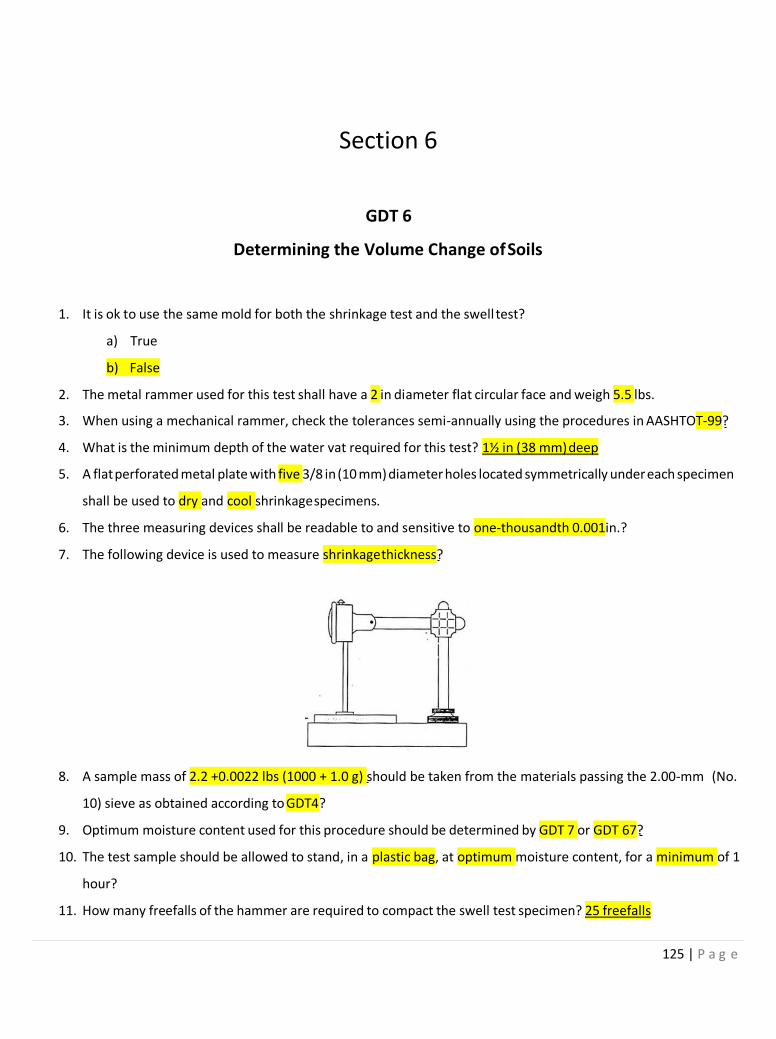
125 | P a g e
Section 6
GDT 6
Determining the Volume Change of Soils
1. It is ok to use the same mold for both the shrinkage test and the swell test?
a) True
b) False
2. The metal rammer used for this test shall have a 2 in diameter flat circular face and weigh 5.5 lbs.
3. When using a mechanical rammer, check the tolerances semi-annually using the procedures in AASHTOT-99?
4. What is the minimum depth of the water vat required for this test? 1½ in (38 mm) deep
5. A flat perforated metal plate with five 3/8 in (10 mm) diameter holes located symmetrically under each specimen
shall be used to dry and cool shrinkage specimens.
6. The three measuring devices shall be readable to and sensitive to one-thousandth 0.001in.?
7. The following device is used to measure shrinkage thickness?
8. A sample mass of 2.2 +0.0022 lbs (1000 + 1.0 g) should be taken from the materials passing the 2.00-mm (No.
10) sieve as obtained according to GDT4?
9. Optimum moisture content used for this procedure should be determined by GDT 7 or GDT 67?
10. The test sample should be allowed to stand, in a plastic bag, at optimum moisture content, for a minimum of 1
hour?
11. How many freefalls of the hammer are required to compact the swell test specimen? 25 freefalls

126 | P a g e
12. Swell test base plates should be preadjusted, so the micrometer reads zero on the 0.875 in. (22.22 mm) constant
of the calibration tool, with the mold removed.
13. Swell specimens should remain in the water vat undisturbed for 20 ½ hours before removing the paper and
recording the final thickness measurement?
14. Calculate the percent swell?
Original Dial Reading .143’’
Final Dial Reading .180’’
Swell % 3.6 %
15. The original thickness measurement, when measuring shrinkage, shall be taken before the specimen is extruded
from the mold?
a) True
b) False
16. Shrinkage specimens shall be allowed to air dry for about 1 hour after compacting and measuring all specimens
to be tested?
17. When determining the final diameter dial reading, the circular end of the specimen should face the same direc-
tion as the dial to ensure proper centering of the specimen?
18. Calculate the percent shrinkage?
B = .758
FT = .750
FD = .740
Shrinkage % 1.3
19. Calculate the total volume change using the results from questions No. 14 and No. 18?
Total Volume Change = 4.9 %

127 | P a g e
Section 7
GDT 7
Determining Maximum Density of Soils
1. The metal mold used in this procedure shall have an approximate volume of 1/30 ft³ (0.000943, ± 0.000008 m³)?
2. A representative test sample, weighing about 10 lbs. (5 kg), should be obtained by using a sampler, or by splitting
and quartering?
3. During sample preparation, a No. 10 (2.00 mm) sieve is used to split the sample into two portions?
4. What size sample is obtained from the thoroughly mixed portion of the materials passing the No. 10 (2.00 mm)
sieve? 6.6 lb (3000 g) sample
5. Each layer of soil material shall be compacted in the mold, using 25 blows from the rammer, dropped from 1 ft
(304.8 mm) above the soil.
6. How many layers of material are compacted in the mold? 3
7. When compacting the test sample, the mold should rest on a rigid foundation weighing at least 200 lbs (90 kg)?
8. How often should the soil material be removed from the face of the rammer? after every 25th blow
9. A straightedge is used to level the sample to the top and bottom of the cylinder mold?
10. Calculate the wet weight of the compacted soil in pounds per cubic foot?
Weight of Mold 2002g
Weight of Mold + Sample 3800g
Mold Correction Factor 0.0665
Wet Weight, lbs./ft3 119.6
11. Samples for percent moisture are obtained by slicing the compacted soil through its center, and removing a 100
gram sample from the center of the compacted soil?
12. Calculate the percent moisture content?
Weight of Wet Soil 100g
Weight of Dry Soil 94g
Moisture % 6.4
13. What amount of water needed to increase the moisture content of a 3000g sample by 1 percent? 1 oz (30 ml)

128 | P a g e
14. Moisture content of the soil should be increased by, (1 percent to 2 percent for sandy soils, 2 percent to 3 per-
cent for clay soils).
15. Repeat procedure until the soil becomes very wet and the wet weight of the compacted soil substantially de-
creases?
16. Calculate the dry weight of the compacted soil in pounds per cubic foot?
Wet Weight, lbs./ft3 119.6
Moisture % 6.4
Dry Weight, lbs./ft3 112.4
17. Plot the moisture density data points, draw a smooth curve connecting the points?
Dry Density % Moisture
100.0 6.0
104.8 8.0
108.0 10.0
104.0 12.0
18. For classification purposes, interpret the maximum dry density as the highest density obtained in the test series,
and the optimum moisture as the moisture content at that respective density?
19. If the soil contains material retained on the No. 10 (2.00 mm) sieve and the specifications show density require-
ments on the total sample, you must correct the maximum dry density to reflect the percentage of Plus No. 10
(2.00 mm) material?
20. It is not necessary to correct the density for percentage of Plus No. 10 (2.00 mm) material when determining
maximum densities for compaction control?
a) True
b) False
Moisture Density Curve 110
108
106
104
102
100
98
0 2 4 6 8 10 12 14
% Moisture
Dry
Den
sity

129 | P a g e
21. Correct the maximum dry density and optimum moisture using the conversion factors in Tables 1D - 7D for
maximum dry density and Tables 1M - 10M for optimum moisture?
- No. 10 Maximum Dry Density 108.0
- No. 10 Maximum Optimum Moisture 10.0
% Plus No. 10 Material 20.0
Corrected Maximum Dry Density 113.9
Corrected Optimum Moisture 8.5
Section 8
GDT 49
Determine the Theoretical Maximum Dry Density and Optimum Moisture of Soil Aggregate
Mixtures
1. The mold in this procedure will have an approximate diameter of 6 inches and height of 6inches.
2. The metal rammer will have a diameter of 2 in² and a weight of 10lbs (4.536kg). The rammer will be dropped at a
height of 18 inches from the surface the soil.
3. What size sample is taken and dried in a drying apparatus at a temperature not to exceed what temperature?
4. Any material larger than the ¾ sieve shall be discarded and replaced with material retained on the No. 4. sieve.
5. A representative sample of approximately 25lbs(11.34kg) is needed to perform the test.
6. What should the initial moisture content of the sample be mixed to? 3% below optimum
, 140°F(60°C) 50lb(22.68kg)

130 | P a g e
7. Each moisture content shall be compacted with 56 uniform blows in five equal layers?
8. After the mold has been compacted, the collar is removed, and the compacted material timed where?
a) at the top of the mold
b) bottom of the mold
c) Both top and bottom
9. Calculate the wet weight of the compacted soil in pounds per cubic foot?
Weight of Mold 5920g
Weight of Mold + Sample 11245g
Mold Correction Factor 0.02950
Wet Weight, lbs./ft3 157.1
10. Samples for percent moisture are obtained by slicing the compacted soil through its center, and removing a 500
gram sample from the center of the compacted material?
11. Calculate the percent moisture content?
Weight of Wet Soil 500g
Weight of Dry Soil 472.8g
Moisture % 5.75
12. Moisture samples will be dried in an oven capable of maintain what temperature? 230°F(110°C)T
13. Moisture will be increased at a rate of approximately 1% and material compacted until a decrease or no change in
the wet weight is reported.
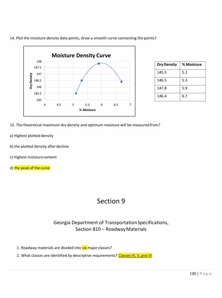
130 | P a g e
14. Plot the moisture density data points, draw a smooth curve connecting the points?
Dry Density % Moisture
145.5 5.1
146.5 5.3
147.8 5.9
146.4 6.7
15. The theoretical maximum dry density and optimum moisture will be measured from?
a) Highest plotted density
b) the plotted density after decline
c) Highest moisture content
d) the peak of the curve
Section 9
Georgia Department of Transportation Specifications,
Section 810 – Roadway Materials
1. Roadway materials are divided into six major classes?
2. What classes are identified by descriptive requirements? Classes IV, V, and VI
Moisture Density Curve 148
147.5
147
146.5
146
145.5
145
4 4.5 5 5.5
% Moisture
6 6.5 7
Dry
Den
sity
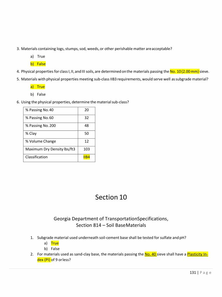
3. Materials containing logs, stumps, sod, weeds, or other perishable matter are acceptable?
a) True
b) False
4. Physical properties for class I, II, and III soils, are determined on the materials passing the No. 10 (2.00 mm) sieve.
5. Materials with physical properties meeting sub-class IIB3 requirements, would serve well as subgrade material?
a) True
b) False
6. Using the physical properties, determine the material sub-class?
% Passing No. 40 20
% Passing No. 60 32
% Passing No. 200 48
% Clay 50
% Volume Change 12
Maximum Dry Density lbs/ft3 103
Classification IIB4
Section 10
Georgia Department of TransportationSpecifications,
Section 814 – Soil Base Materials
1. Subgrade material used underneath soil-cement base shall be tested for sulfate and pH?
a) True
b) False
2. For materials used as sand-clay base, the materials passing the No. 40 sieve shall have a Plasticity In-
dex (PI) of 9 or less?
131 | P a g e
132 | P a g e
3. Particles with diameters greater than 2 in (50 mm) shall be removed before depositing topsoil or
sand-clay on the road?
4. Laboratory specimens for a soil-cement mix design should be cured for 7 days and should produce an
unconfined compressive strength of at least 450 psi (3.1 MPa)?
5. Soils meeting classes IIB2 are suitable for use as soil-cement material?
a) True
b) False
6. Materials passing the No. 10 sieve, used in sand-clay base, shall have a maximum dry density of
110+lbs/ft³?
7. What test method is required to perform PH testing for materials used in soil-cement base construc-
tion?
a) GDT 98
b) GDT 6
c) T 96
d) None of the above
Top Related