


![Learning Automatic Schedulers through Projective … · Learning automatic schedulers through projective reparameterization Ajay Jain movsdxmm5, qword ptr[rsp+0x20] movsdxmm3, qword](https://static.fdocuments.in/doc/165x107/5fd7e613f108535a954c7172/learning-automatic-schedulers-through-projective-learning-automatic-schedulers-through.jpg)
Languages
Pages
Legal


NWPP
After-the-Factandand
System Schedulers Meetings
October 15-16, 2013 –Portland, OR

Next Meeting…Next Meeting…
October 21October 21--22, 201422, 2014P tl d ORP tl d OR–– Portland, ORPortland, OR
If you are interested in participating If you are interested in participating y p p gy p p gon the Agenda Committee on the Agenda Committee
please contact:please contact:
[email protected]@nwpp.orgor or
(503) 445(503) 445 10791079(503) 445(503) 445--10791079

AAFFTTEERR--TTHHEE--FFAACCTT AANNDD SSYYSSTTEEMM SSCCHHEEDDUULLEERRSS MMEEEETTIINNGG OOccttoobbeerr 1155--1166,, 22001133
DDoouubblleeTTrreeee bbyy HHiillttoonn –– PPoorrttllaanndd 1000 NE Multnomah Portland, OR 97232
AAggeennddaa
OOcctt.. 1155,, 22001133 –– 11::0000 pp..mm.. ttoo 55::0000pp..mm.. Welcome and Arrangements ChaRee DiFabio, NWPP 1. WECC ISAS – Status Update Andy Meyers, BPA
WIT Checkout document WIAB Training and Test Plan
IInnttrroodduuccttiioonnss BBrreeaakk 2. FERC Order 764 Kathy Anderson, IPC
PacifiCorp Changes Kathee Downey, PAC 3. Status Update - WEQ-EIR (replacement of WIT Registry) Bob Harshbarger, PSE 4. NWPP Corporate Update Jerry Rust, NWPP EEvveenniinngg RReecceeppttiioonn 55::0000 ttoo 88::0000 OOcctt.. 1166,, 22001133 –– 88::0000 aa..mm.. ttoo 1122::0000 pp..mm.. Welcome Back ChaRee DiFabio, NWPP 1. Solar Magnetic Events Richard Becker, BPA 2. What is an ATF Tag? Amy Lubick, NWMT
How shall it be used? ATF Guidelines Update
3. BPA’s alternate scheduling center Lou Miranda, BPA BBrreeaakk 4. WECC Bifurcation – Status Update Craig Williams, WECC 5. Enhanced Curtailment Calculator – replacing WEBSAS Craig Williams, WECC 6. PAC/ISO EIM – Status Update John Apperson, PAC 7. Burning Issues All
NWPP Settlement Price USF Curtailments (seasonal issues – What worked. What didn’t?)
CClloossiinngg && DDoooorr PPrriizzeess

Presenter Biographies –
After-the-Fact Meetings & System Schedulers
October 15-16, 2013 – Portland, OR
WECC ISAS – Status Update & WIAB Training and Test Plan
Andy Meyers is the WECC ISAS Vice Chair and is the Supervisor Preschedule at Bonneville Power Administration – Power.
FERC Order 764 Task Force
Kathy Anderson is the Transmission Operations Leader at Idaho Power Company overseeing Open Access Transmission Tariff Administration, Pre-schedule, and ATF Interchange Operations. She joined Idaho Power in 2005 and has been in her current position since 2009. A graduate of Boise State University, Kathy is NERC certified and serves on the WECC Market Interface Committee and the Interchange Scheduling and Accounting Subcommittee (ISAS).. Kathy was the chair of WECC’s Order 764 Task force which reviewed the impacts of 15-minute scheduling for the WECC footprint.
FERC Order 764 Task Force – PacifiCorp Changes
Kathee Downey joined PacifiCorp in 1989 and has worked in various departments including wholesale sales, regulatory, back office and system operations. Currently, she is the Manager of Balance and Interchange in grid operations. Kathee has been actively involved in various WECC, Joint Initiative, and Northwest Power Pool efforts. Along with many others, she was a participant on the WECC Joint Guidance Committee task force addressing 15-minute scheduling. Kathee is a graduate of San Diego State University and holds a Bachelor of Science in Criminal Justice and is NERC certified - Balance and Interchange. As of this writing, Kathee has 729 working days left to retirement. WEQ-EIR – Status Update
Bob Harshbarger is currently the OASIS Trading Manager at PSE. He has been at times involved with various NERC, NAESB, WECC, wesTTrans OASIS, Joint Initiative, and ColumbiaGrid activities.
Member of the NERC Coordinate Interchange Standards Drafting Team Member of the NERC Interchange Subcommittee Co-Chair of the NERC/NAESB Joint Electric Scheduling Subcommittee. Member of the NAESB OASIS Subcommittee. Vice-Chair of the NAESB WEQ Executive Committee. Former Chair of the WECC Market Interface Committee. Chair of the Dynamic Scheduling System Operating Committee. Member of the wesTTrans OASIS committee. Occasional ISAS groupie
Also, Bob is married, has 3 three grown children, and lives in Redmond, WA.
NWPP Corporate Update
Jerry D. Rust joined the Northwest Power Pool January 1, 2001 as President. For the majority of 2000, Jerry consulted on power issues for several software companies. Prior to that, he worked at PacifiCorp for 23 years, where he served as managing director of PacifiCorp’s revenue organization and managing director of the transmission systems group. Jerry joined PacifiCorp in 1977 as an engineer and held positions in power resources, financial analysis, field operations, customer service, sales support and national sales. Mr. Rust was graduated from the University of Wyoming with a degree in electrical engineering. He has furthered his education with numerous courses from various schools (University of Washington, Washington State University, Colorado School of Mines, and others). Jerry is one of the Western Electricity Coordinating Council’s North American Electric Reliability Council Operating Committee Representatives.
Solar Magnetic Events
Richard Becker is the Manager of Substation Engineering in Bonneville Power Administration’s Transmission Engineering and Technical Services organization, and a licensed professional engineer with a Bachelor of Science degree in Electrical Engineering from the University of Idaho. He has over 26 years experience in substation engineering, operation, and maintenance, and expertise in the areas of system protection & control and substation equipment performance. What is an ATF Tag?
Amy Lubick has been with NorthWestern Energy since 2005 and in her current position for the past 7 years doing ATF, settlements and numerous reporting and analysis tasks. She serves on the WECC Interchange Scheduling and Accounting Subcommittee and is currently the Chair of the After-the-Fact Work Group. Amy is a graduate of the University of Montana in Accounting. She recently married and lives in Butte, MT with her husband and two teenage step daughters. BPA’s Alternate Scheduling Center
Lou Miranda has been with BPA for over 20 years and has worked in both Power and Transmission Scheduling for over a decade. A graduate of Portland State University, Lou is a native of the Pacific Northwest. WECC Updates – MIC / NAESB Gas Electric Harmonization
Craig L. Williams has a background in the energy industry starting at the vendor level and progressing through the plant, system, and interconnection levels. Craig worked domestically and internationally with Siemens as a nuclear engineer, worked with PSE&G at the Hope Creek Nuclear Station in southern New Jersey, and worked with PacifiCorp’s real-time trading group in Portland, OR. In 2011 Craig joined the Western Electricity Coordinating Council and currently works as the Market Interface Manager. Craig has Bachelors of Applied Physics from Brigham Young University, a Masters in Nuclear Engineering from the Georgia Institute of Technology, and an MBA in Securities Finance from Portland State University.

PAC/ISO EIM – Status Update
John Apperson has been the trading director at PacifiCorp located Portland, Oregon, since 2000 and is responsible for short and long term trading and scheduling for electricity and natural gas as well as real-time electricity trading and operations. PacifiCorp is the third largest investor-owned utility within the western interconnection and has a robust portfolio of coal-fired, natural gas-fired, hydro, and wind generation serving retail load in six states.
Mr. Apperson has experience in many aspects of the utility industry including merchant operations planning, wholesale marketing, transmission planning, utility distribution operations and planning. He participated in the 2012 Northwest Power Pool energy imbalance market effort and most recently has been involved in the design and development of the California ISO energy imbalance market. NWPP Meeting MC
ChaRee DiFabio joined the joined the Northwest Power Pool in July 2000. She is currently the Reserve Sharing Group Committee Manager and oversees all related activities of this group as well as the program. Also, she provides support to the NWPP Operating Committee (OC), NWPP Training, various subcommittees and work groups through coordination, meeting facilitation, and informational reporting on behalf of the membership to the internal companies and other organizations such as WECC and NERC. Prior to working for the NWPP she worked for Idaho Power Company for 5 years at the Boise Bench Substation where she worked with the System Dispatch, After-the-Fact, and the System Scheduling groups.

Andy MeyersAndy MeyersInterchange Scheduling and Accounting
Subcommittee (ISAS) Vice ChairSubcommittee (ISAS) Vice Chair
NWPP After-The-Fact & System Schedulers Meeting
October 2013
Portland, OR

Agenda
• What is ISAS
Agenda
• 2013 Goals
• What Does WECC Bifurcation mean to ISAS
• 2014 WECC Spring Scheduler’s Mtg2014 WECC Spring Scheduler s Mtg
• Other Forums (NERC & NAESB)
• 2014 Mtg Dates
2

ISAS StructureISAS Structure
3

ISAS & Its Work Groups• ISAS
ISAS & Its Work Groups
o Chair: Brenda Ambrosi, BC Hydro; Vice Chair: Andy Meyers, BPA; Secretary: Kathy Anderson, Idaho Power Company
o Purpose is to develop regional scheduling and tagging standards, criteria, and guidelines that promote compliance with FERC and NERCguidelines that promote compliance with FERC and NERC
o Foster development and use of common terminology and methods for scheduling and tagging practices
• After-The-Fact Work Group (ATFWG) o Chair: Amy Lubick, NorthWestern Energy
o Purpose is to research and facilitate resolutions to energy accounting issues
• Real Time Scheduling Work Group (RTSWG) Ch i Mik Pf i t S lt Ri P j to Chair: Mike Pfeister, Salt River Project
o Purpose is to resolve real time reliability and scheduling
4

ISAS & Its Work Groups• E-Tagging Issues Work Group (EIWG)
Ch i Li Wild Gil Ri P LP [ k E t P G ]
ISAS & Its Work Groups
o Chair: Lisa Wildes, Gila River Power, LP [aka Entegra Power Group]
o Purpose is to research and facilitate resolution to identified e-Tag issues relating to reliability
• Regional Interchange Criteria Work Group (IWG)Regional Interchange Criteria Work Group (IWG)o Chair: Danielle Johnson, Bonneville Power Administration
o Purpose is to develop regional interchange criteria, policies, and guidelines
o Owner for Annual WIAB test.
• Electronic Scheduling Work Group (ESWG)o Chair: Raymond Vojdani, Western Area Power
o Purpose is to research and facilitate resolution of identified electronic scheduling issuesissues
o Provide expertise for the WIT, WECC Registry and EIR as well as work with vendor to enhance these business systems
5

2013 Goals
• ATF Manual
2013 Goals
• Guideline for e-Tag Default Ramp Durations
• Implementation of WIAB Test Plan
S ISAS i t t d d t WECC S t O t• Secure ISAS instructors and update WECC System Operator Training class materials for:
o Interchangeg
o Schedulers
• 2013 WECC Spring Schedulers’ Meeting
D t i• Documents review
• Modernize existing interchange Regional Criteria
6

Guideline e-Tag Default Ramp D ti• Applicable Tag Types
DurationsApplicable Tag Typeso Normal, Capacity, Recallable, Emergency,
Loss Supply Dynamic & Psuedo-TieLoss Supply, Dynamic, & Psuedo Tie
• Request TypesNew Curtailment Reload Adjustmento New, Curtailment, Reload, Adjustment, Termination, & Extension
7
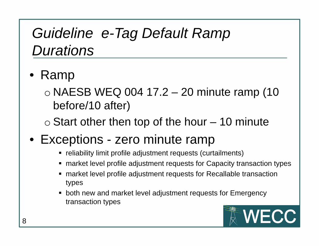
Guideline e-Tag Default Ramp D ti• Ramp
DurationsRampo NAESB WEQ 004 17.2 – 20 minute ramp (10
before/10 after)before/10 after)
o Start other then top of the hour – 10 minute
• Exceptions zero minute ramp• Exceptions - zero minute ramp reliability limit profile adjustment requests (curtailments)
market level profile adjustment requests for Capacity transaction types
market level profile adjustment requests for Recallable transaction types
both new and market level adjustment requests for Emergency transaction types
8
transaction types

Regional CriteriaRegional Criteria
9

WECC Bifurcation
• What does WECC bifurcation mean to ISAS
WECC Bifurcation
What does WECC bifurcation mean to ISASo WECC divided into Regional Entity (WECC)
and Reliability Coordination Company (RCCo)and Reliability Coordination Company (RCCo)
o Opportunity to look at our purpose and structure of our subcommittee and review thestructure of our subcommittee and review the need and function of our work groups
10

WECC Spring Scheduler’s Mtg
• 2013 Meeting
WECC Spring Scheduler s Mtg
2013 Meetingo May 6th & 7th in San Diego California
o Sempra Energy hosted and providedo Sempra Energy – hosted and provided conference space
o 54 registered in person attendeeso 54 registered in person attendees
o 12 webinar participants
o Location Location Locationo Location, Location, Location San Diego – not as big a draw as anticipated
11

WECC Spring Scheduler’s Mtg
• Communication Plan & Advertising
WECC Spring Scheduler s Mtg
Communication Plan & Advertisingo WECC exploder’s reached some but feedback
was that many marketer’s weren’t aware of thiswas that many marketer s weren t aware of this year’s meeting
• Future of Scheduler’s MeetingFuture of Scheduler s Meetingo Every other year or every third year?
o OC would like to see changes for 2014o OC would like to see changes for 2014 No Webinar
Leverage off another meeting
12
Leverage off another meeting
Agenda Committee start earlier

WECC Spring Scheduler’s Mtg
• 2014 Scheduler’s Meeting
WECC Spring Scheduler s Mtg
2014 Scheduler s Meeting
• Looking for an organization to serve as the hosthost.
• Seeking volunteers to participate in the A d C ittAgenda Committee
13

Other Forums
• NERC
Other Forums
NERC o NERC Project 2008-12 Coordinated
Interchange StandardsInterchange Standards
o Open for 45 day comment – Closes 11/13
• NAESB• NAESBo NAESB Oasis Subcommittee
NAESB JESSo NAESB JESS Etag Reliability Limit Profiles
14

E-Tag Reliability Profiles
• Only the last reliability limit is retained as part of
E Tag Reliability Profiles
Only the last reliability limit is retained as part of current profile on etag
• When multiple entities curtail/reload an etag they p g ycan override reliability limit
• JESS requested informal comments by 9/6q y
• JESS will discuss adopting the following recommendation to e-Tag spec
o Change the profile calculation procedure for reliability limits such that the reliability limit at any point in time is determined by finding the most recent reliability limit for each request author and then taking the lowest of these values
15

Future ISAS Dates
• 2014 Meeting Dates
Future ISAS Dates
2014 Meeting Dates January 29-30 (workgroup meetings 1/28)
April 23-24 (workgroup meetings 4/22)April 23 24 (workgroup meetings 4/22)
August 20-21 (workgroup meetings 8/19)
• Get involved and participate at WECC orGet involved and participate at WECC or other forums
• Contact Info: Andy Meyers (apmeyers@bpa gov)Contact Info: Andy Meyers ([email protected])
16

Questions?
Andy Meyers – Bonneville PowerAndy Meyers Bonneville Power
503-230-3014

A l WIAB T tAnnual WIAB Test Danielle Johnson
October 15,2013October 15,2013
NWPP Scheduler Conference
Portland, OR

What is the WIAB Yearly Test?
A test of the coordinated back-stop scheduling process that protects the li bilit f th id d i I t h A th it (IA) E
y
reliability of the grid during an Interchange Authority (IA) Emergency or Outage.
Testing will be in accordance to the requirements in the WECCTesting will be in accordance to the requirements in the WECC Interchange Authority Backup Regional Business Practice (WIAB) INT-020-WECC-RBP-1.1
Not all requirements will be tested Primarily the required verbal communication between BA TP and Primarily the required verbal communication between BA, TP and
PSE
Testing will be conducted along side day to day business, no outage of IA No impact to Production!IA. No impact to Production!
The test requires a minimum of two adjacent BA, one TP in between the two BA, one PSE, in coordination with the RC and WECC
2
, ,

Why do we need to test a Regional Business Practice?It is a rare event.• WIAB implemented once in 2012.
– Known outage.o This was for a hardware upgradeo This was for a hardware upgrade.
– The outage was well known days ahead of time which allowed for the region to be prepared.
– The last for a 1.30 hours
• A yearly test will provide an opportunity – Ensure that the requirements still meet the need– BA TPs PSE a chance to train staffBA, TPs, PSE a chance to train staff – Identify changes to software, technology, processes
and communication, etc….
3

The how in a nutshellThe how in a nutshell
• Test can last up to ~4 hoursp• A WECC net message sent stating
o TEST TEST WIAB INT-20-WECC-RBP-1.1 FOR [DATE] START[TIME] STOP [TIME] TEST TEST[ ] [ ]
o WECC will send out a email, couple of weeks prior to, to all WECC members with the date and time of the test a couple of weeks prior to.
Snap shot production NSI at the beginning of the• Snap shot production NSI at the beginning of the test. This will be utilized as the starting point of NSI
• Create new transaction.o Attachment A Transaction Data Template process
• Submit verbal Adjustments verbal CurtailmentSubmit verbal Adjustments, verbal Curtailment, verbal check outs, other verbal changes
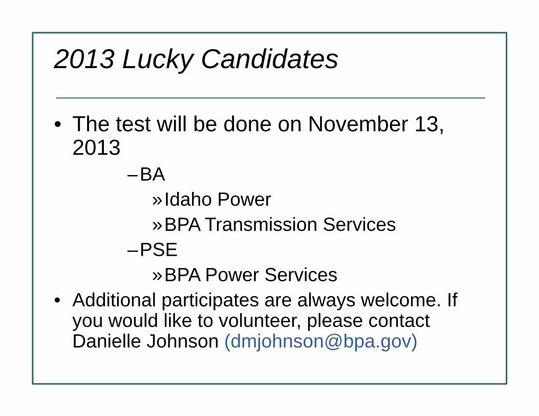
2013 Lucky Candidates
• The test will be done on November 13,The test will be done on November 13, 2013
–BA»Idaho Power»BPA Transmission Services
–PSE»BPA Power Services
• Additional participates are always welcome. If you would like to volunteer, please contact Danielle Johnson (dmjohnson@bpa gov)Danielle Johnson ([email protected])

Questions?
Andy MeyersAndy Meyers
503-

Kathy Anderson, Idaho Power CompanyNWPP Schedulers MeetingNWPP Schedulers Meeting
October 2013Portland, OR

Order 764 Task Force Mission Order 764 Task Force
Created by the Joint Guidance Committee to assess the impacts of 15 minute scheduling in the Western impacts of 15 minute scheduling in the Western Interconnection and how identified impacts affect the reliability and commercial activities of WECC.
Task force to provide complete set of findings and recommendations to JGC no later than March 31, 2013

Task Force Responsibilities According to Scope Statement
Identify and analyze potential scheduling issues lti f i t h d li i th t resulting from 15 minute scheduling in the western
interconnection including but not limited to seams issues.
Review existing WECC, NERC and NAESB guidelines, standards and criteria that may be impacted by Order 764764
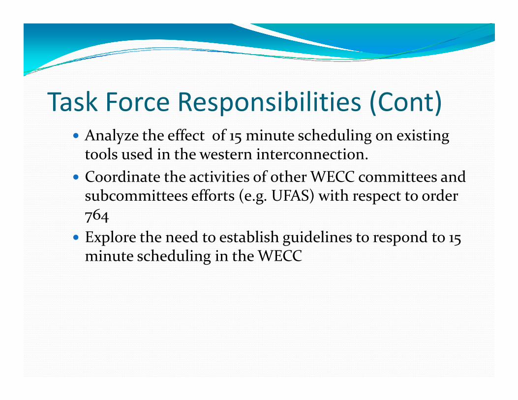
Task Force Responsibilities (Cont) Analyze the effect of 15 minute scheduling on existing tools used in the western interconnection.
Coordinate the activities of other WECC committees and Coordinate the activities of other WECC committees and subcommittees efforts (e.g. UFAS) with respect to order 764
Explore the need to establish guidelines to respond to 15 minute scheduling in the WECC
Task Force Leadership Chair – Kathy Anderson, System Operations Leader, Idaho Power Company
Vice Chair Marilyn Franz Staff Consultant Vice Chair – Marilyn Franz, Staff Consultant –Transmission Services, NV Energy Membership and meetings were open to all interested p g pstakeholders

Task Force Subgroups Subgroups were developed to work on issues to bring back to the larger task force. Coordination of Net Schedule Interchange Marilyn Coordination of Net Schedule Interchange – Marilyn Franz, NV Energy Questions: Do we check out every 15 minutes? Do we Q y 5checkout the 15 minute intervals after each hour or the hourly integrated value? Is there possible checkout automation?automation?
Group determined what the proposed intra‐hour checkouts would look like.

Proposed Checkouts
Task Force Subgroups (Cont) Transmission Pre‐emption Intra‐hour – Kathee Downey, PacifiCorpWhat is required for intra hour schedules if the path What is required for intra‐hour schedules if the path becomes overscheduled? Are curtailments required every 15 minutes as path schedules change?
Recommendation will be that curtailments will occur prior to the hour for the entire hour and then for the next 15 minute intervals if path becomes next 15 minute intervals if path becomes overscheduled during that time.
Task Force Subgroups (Cont) Interaction with Market Structures and Seams Issues with CAISO – Jim Price, CAISOCAISO has an automated process for real time unit CAISO has an automated process for real time unit commitment – market optimization process – used by market participants to make adjustments.
Information on the CAISO process can be found on the CAISO website.

Existing Document Review The task force reviewed NERC, WECC, and NAESB documentation to see if there are any impacts with 15 minute schedulingminute scheduling.
Some inconsistencies with timing tables in the NERC Standards with “on time” tags and the OATT 20 minute before the “scheduling interval”. Standards say 10 minutes before the ramp.
This is in the process of going through the NERC This is in the process of going through the NERC process to be updated.
Integration of Schedules “RoundingIntegration of Schedules Rounding Issue”
An issue with sub‐hourly schedule rounding has been identified where total schedules could exceed total transmission reservations While this is not expected to transmission reservations. While this is not expected to cause reliability issues intra‐hour, concerns exist for possible manipulation of sub‐hourly schedules and f h f i h li billi d lafter‐the‐fact with compliance, billing, and settlement
A Survey was sent out to ask the task force members their opinions.their opinions.

Rounding Survey Make no changes and round sub‐hourly schedules according to existing rules.
Truncate any schedule that is less than an hour in Truncate any schedule that is less than an hour in duration when computing the MW value for the hour (e.g. 2.5MW would become 2 MW).
Require that sub‐hourly schedules and sub‐hourly schedule changes must be done in increments of 4MW to eliminate hourly rounding concernsto eliminate hourly rounding concerns.
Rounding Survey Round up during the 1st and 3rd intra‐hour scheduling interval and round down during the 2nd and 4th
intervalsintervals. Adjust the accounting values to include a 1/10th of a MW. (e.g. 2.1MW, 2.2MW etc., would be okay)

Rounding Survey The survey was distributed to the task force exploder on January 8, 2013.
Comment period was open until January 30 2013 Comment period was open until January 30, 2013. Results indicated that the majority said to leave as it stands, there was some interest in having WECC explore , g pthe option of 1/10th MW accounting.

Order 764‐A On December 20, 2012, FERC released Order 764‐A.
Deadline for compliance has been moved from September 11 2013 to November 12 2013September 11, 2013 to November 12, 2013.
Confirmed that intra‐hour scheduling applies to ALL transmission customers that schedule under the OATT (network and PTP)

Order 764‐A Confirmed that schedules for firm transmission service will continue to have curtailment priority over schedules for non‐firm transmission servicefor non firm transmission service.
This eliminates the “no bumping” rule many Transmission Service Providers in the Western Interconnection have today.

Initial Recommendations 15‐minute scheduling intervals will be xx:00‐xx:15, xx:15‐xx:30, xx:30‐xx:45, and xx:45‐xx:00.
Intra hour Transactions will allow use of firm and non firm Intra‐hour Transactions will allow use of firm and non‐firm TSRs.
Intra‐hour Transactions will allow use of new or existing gTSRs.
Intra‐hour Transactions will allow use of redirects, either fi fifirm or non‐firm.
E‐Tags submitted in Pre‐schedule may be submitted with 15‐minute interval scheduling (customer discretion)5 g ( )

Initial Recommendations Firm transmission use would preempt non‐ firm transmission use if submitted at least 20 minutes before the impacted scheduling interval Non‐firm transmission the impacted scheduling interval. Non firm transmission use of a higher priority would preempt non‐firm transmission use of a lower priority if submitted at least 20 i b f h i d h d li i lminutes before the impacted scheduling interval.
Requests for Interchange (e‐Tags) must be submitted at least 20 minutes prior to the start of the scheduling least 20 minutes prior to the start of the scheduling interval to be considered ”On‐Time” (not “Late”).

Initial Recommendations A Request for Interchange that is Late (submitted with less than 20 minutes prior to the impacted scheduling interval’s start time) will be marked as Late *Revise interval s start time) will be marked as Late. *Revise NERC timing tables to make this occur.
If needed Reliability Limits (curtailments) will occur If needed, Reliability Limits (curtailments) will occur prior to the top of the hour (as they do today) for all scheduling intervals in the upcoming hour that exceed a path scheduling limit, and Reliability Limits (curtailments/reloads) will occur within the hour as needed needed.

Initial Recommendations At a minimum, ATC will continue to be calculated as Transmission Service Providers currently calculate today. Order 764 neither requires Transmission Service Providers Order 764 neither requires Transmission Service Providers to provide an intra‐hour transmission service product nor does it require more frequent calculations of ATC than h d H FERC did l d what occurs today. However, FERC did not preclude a
Transmission Service Provider from offering a sub‐hourly product if they choose.p y
Initial Recommendations The top of the hour ramp would remain 20 minutes. Ramp duration for the 15‐minute scheduling intervals would be a 10‐minute straddle ramp10 minute straddle ramp.
Balancing Area Checkouts will be as reflected in the slide above.

Impacts on Unscheduled Flow UFAS does not plan on moving from the current hourly process to a 15‐minute interval. Any new schedules submitted in the hour will be assessed by the webSAS tool submitted in the hour will be assessed by the webSAS tool to determine the impact on the current USF Event. If the tool determines that the transaction creates a negative i b d h TDF f h i h i h impact based on the TDF of the transaction, the intra‐hour transaction will be curtailed by the tool. This is how it works today for any hourly e‐Tag submissions. The tool y y y gwill work the same for any intra‐hour e‐Tag as well.
Impacts on EMS Systems The Order 764 Task Force recognizes that some entities will need to modify how often the NSI value is pulled into their EMS systems and controlled to With the their EMS systems and controlled to. With the implementation of 15‐minute scheduling, entities should ensure their EMS systems are pulling in NSI values upon h l h l h i hi h hchange to control to these value changes within the hour.

Questions

PacifiCorp & FERC Order 764 Final Ruling
Grid Operations – Portland Control CenterGrid Operations Portland Control Center
— presented by —Kathee Downey, Manager – Transmission Grid Operations
PacifiCorp
NWPP Schedulers Meeting - October 15, 2013
PacifiCorp
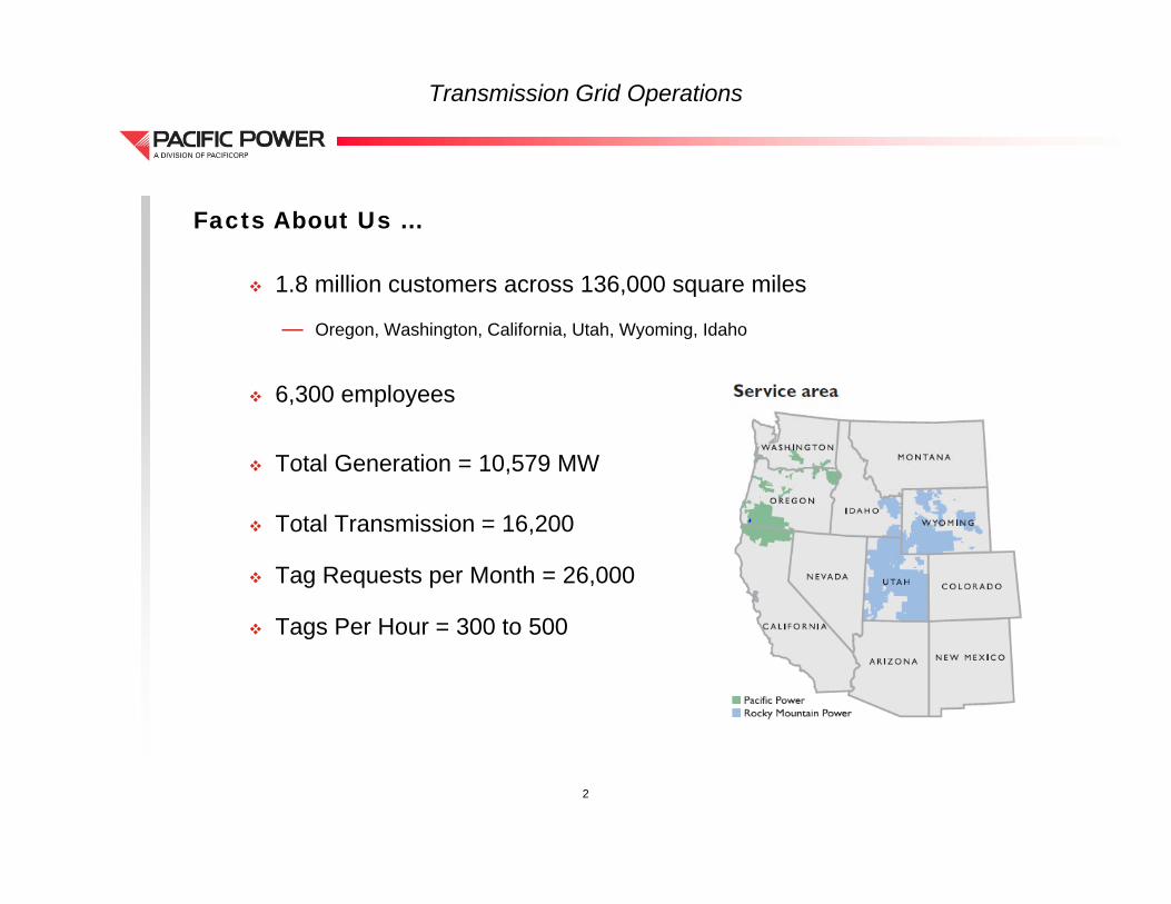
Transmission Grid Operations
1 8 million customers across 136 000 square miles
Facts About Us …
1.8 million customers across 136,000 square miles
— Oregon, Washington, California, Utah, Wyoming, Idaho
6 300 employees 6,300 employees
Total Generation = 10,579 MW
Total Transmission = 16,200
Tag Requests per Month = 26,000
Tags Per Hour = 300 to 500 Tags Per Hour = 300 to 500
2
Transmission Grid Operations
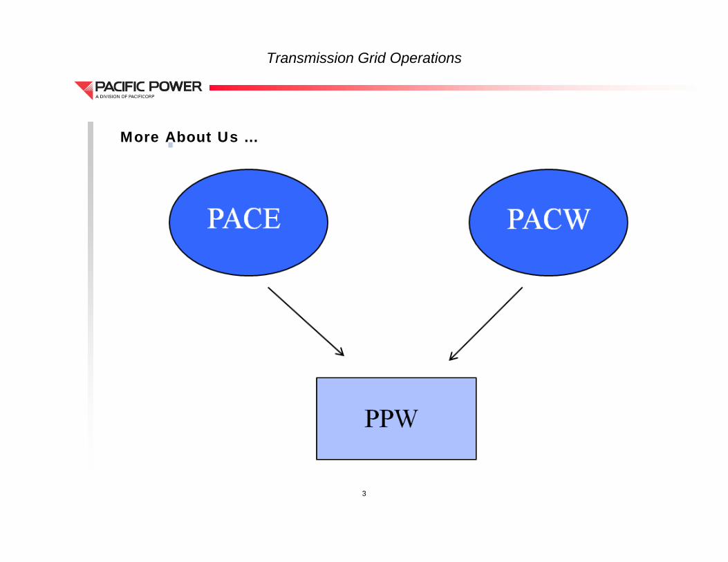
More About Us …
3
Transmission Grid Operations
E T M t
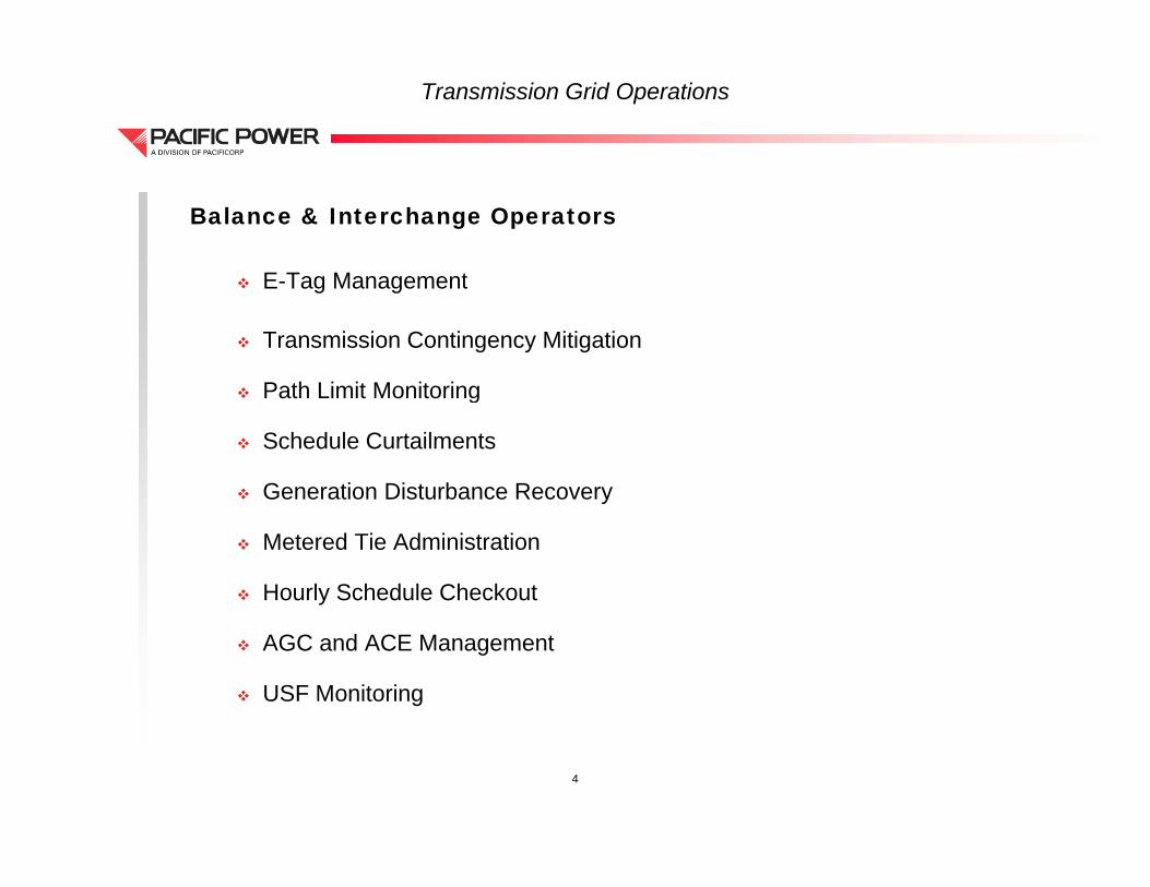
Balance & Interchange Operators
E-Tag Management
Transmission Contingency Mitigation
Path Limit Monitoring Path Limit Monitoring
Schedule Curtailments
Generation Disturbance Recoveryy
Metered Tie Administration
Hourly Schedule Checkout
AGC and ACE Management
USF Monitoring
4

Transmission Grid Operations
N D k
FERC Order 764 Compliance
New Desk
— Hired 3 new FTE’s
— Will this be enough?
Split Responsibilities
— Transmission & Congestion Management
R l Ti T i d C ti i— Real-Time Tagging and Contingencies
9-person / 9-week rotation
Tool Upgradespg
Business Practice Updates
5
Questions?Q
Transmission Grid Operations Overview
Portland Control Center – Grid Operations
El t i I d tElectric Industry RegistryRegistry
Northwest Power Pool’sNorthwest Power Pool’sATF-System Schedulers Meeting
O t b 15 2013October 15, 2013
Bob Harshbarger, Puget Sound Energy


Electric Industry Registry
Registry History
EIR Development
EIR Content
Registry Concepts Registry Concepts
Publications
Access Access
Schedule
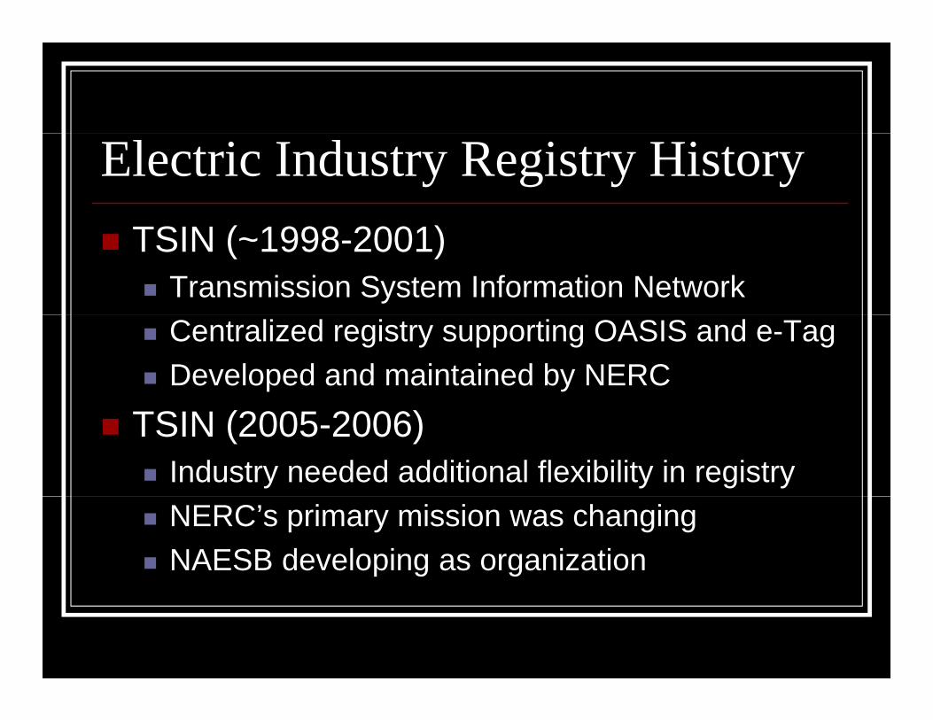
Electric Industry Registry History
TSIN (~1998-2001) Transmission System Information Network
Centralized registry supporting OASIS and e-Tag
Developed and maintained by NERC
TSIN (2005-2006) Industry needed additional flexibility in registry
NERC’s primary mission was changing
NAESB developing as organization

Electric Industry Registry History
EIR Development System requirements document by Joint Electric
S h d li S b itt i 2006Scheduling Subcommittee in 2006
RFPs by NAESB in early 2010
C t t d d d t OATI i 2010 Contracted awarded to OATI in 2010
Cut-over from TSIN in November 13, 2012
Phase 3 migration of WECC adjacency data Phase 3 – migration of WECC adjacency data

Electric Industry Registry Content
Topology Information Interconnections
Control Zones
Source/Sink Points
POR/POD Points
Flowgates
Adj I f ti Adjacency Information

Electric Industry Registry Content
Entity Information Code/Roles
Purchasing/Selling Entities
Regional Entities
Reliability Coordinators
Market operators
B l i A th iti Balancing Authorities
Transmission service providers

Electric Industry Registry Content
Approved Certificate Authorities PKI (secure communications)
e-Tag Information Agent, Approval, Authority Service URLs

Electric Industry Registry Concepts
Maintain Your Data People.
Phone numbers.
Email addresses.
Points of service.

Electric Industry Registry Concepts
Approval Most objects require approval by an entity other
th th i t i titthan the registering entity.
Some approvals have been automated.
Obj t ith l l t i ll h Objects with a manual approval typically have a Pending status for five (5) days.
If approval is not obtained the object is deleted If approval is not obtained, the object is deleted

Electric Industry Registry Concepts
Parent-Child A registered entity enters Code/Role registration
PSEI registers PSEI the BA
A TSP enters a PORPSEI i t th i i t PSEI SYSTEM PSEI registers the service point PSEI.SYSTEM
Multiple parents – a POD and a Sink make-up a POD/Sink adjacencyPOD/Sink adjacency PSEI.SYSTEM-PSEISYS
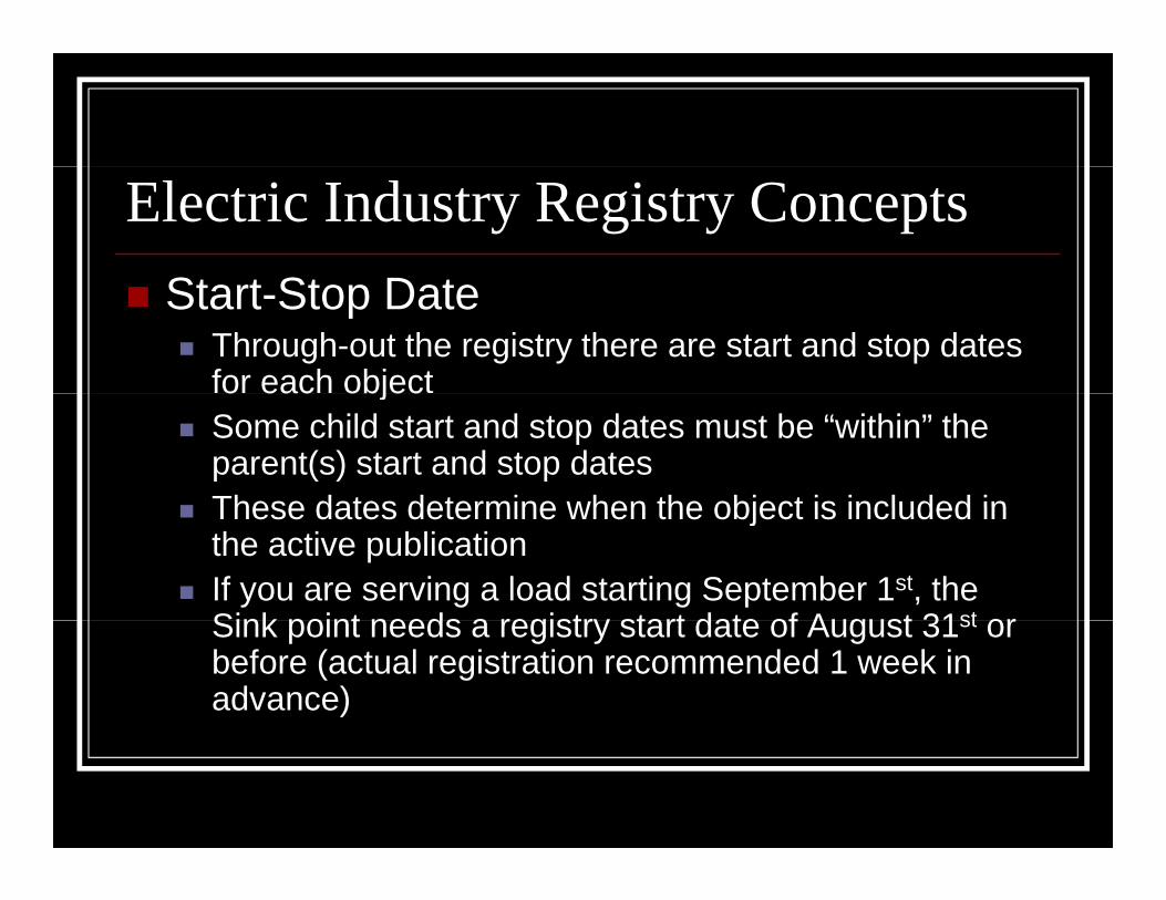
Electric Industry Registry Concepts
St t St D t Start-Stop Date Through-out the registry there are start and stop dates
for each objecto eac objec Some child start and stop dates must be “within” the
parent(s) start and stop dates These dates determine when the object is included in These dates determine when the object is included in
the active publication If you are serving a load starting September 1st, the
Sink point needs a registry start date of August 31st orSink point needs a registry start date of August 31st or before (actual registration recommended 1 week in advance)
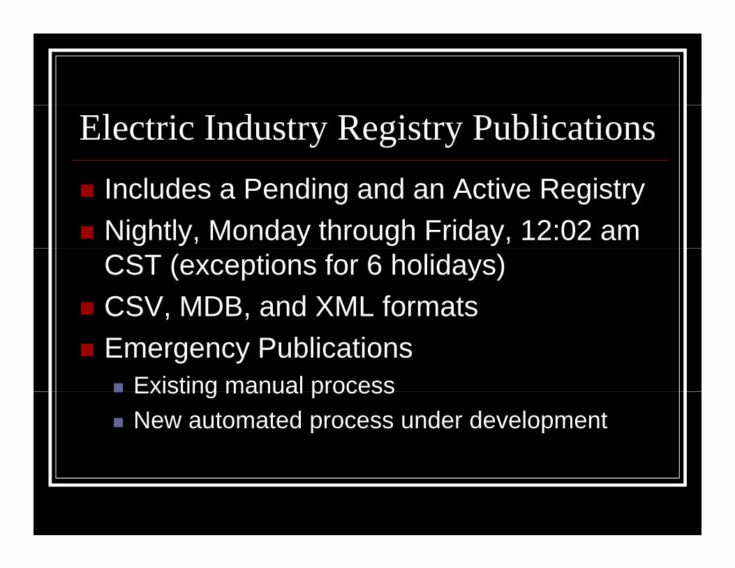
Electric Industry Registry Publications
Includes a Pending and an Active Registry
Nightly, Monday through Friday, 12:02 am CST (exceptions for 6 holidays)
CSV, MDB, and XML formats, ,
Emergency Publications Existing manual process Existing manual process
New automated process under development

Electric Industry Registry Access
NAESB
OATI
Electric Industry Registry Access
NAESB Registry Owner
EIR Business Practice Standards
Process for Registry Enhancements
http://www naesb org/weq/weq eir asp http://www.naesb.org/weq/weq_eir.asp

Electric Industry Registry Access

Electric Industry Registry Access
OATI Registry Administer
Hosts the website
Need Digital Certificate
Annual Registration Fee Annual Registration Fee
Maintains Help Documents
OATI https://www naesbwry oati com/ OATI - https://www.naesbwry.oati.com/

Electric Industry Registry Access

Electric Industry Registry Schedule
OATI Certificate Upgrade October 15, 2013
WECC Adjacency Data October 29, 2013
1.8.1.1 cut-over November 5, 2013
CSV/MDB Retirement November 12, 2013
Auto Emergency Publication December 3, 2013
Electric Industry Registry

NORTHWEST POWER POOLNORTHWEST POWER POOL
Reliability through CooperationReliability through CooperationReliability through CooperationReliability through Cooperation
20132013

Presentation Outline
• Northwest Power Pool Corporation Review• Status of NWPP Training Activities• Update on the NWPP Membership – 4 main
CommitteesCommittees• Other Activities – New Balancing Authority• NERC Standards• Questions• TEST - NOT
2

Vision
Helping the Northwest Power Pool members workHelping the Northwest Power Pool members work together to maintain a reliable and secure Interconnection – today and in the future
3

Historyy
• First pooling of resources in the Northwest occurred in1917p g
• NWPP formed in 1941 by 6 investor-owned utilities 3 staff engineers
• An impetus from the War Production Board in 1942 Ten major private utility systems and Bonneville Power
Administration
Pooled resources to provide power to the war industries
• Maintained after WWII for reliability and coordination
4
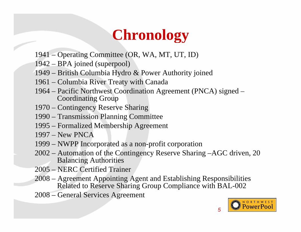
Chronologygy1941 – Operating Committee (OR, WA, MT, UT, ID)1942 – BPA joined (superpool)1949 British Columbia Hydro & Power Authority joined1949 – British Columbia Hydro & Power Authority joined1961 – Columbia River Treaty with Canada1964 – Pacific Northwest Coordination Agreement (PNCA) signed –
Coordinating Groupg p1970 – Contingency Reserve Sharing1990 – Transmission Planning Committee 1995 – Formalized Membership Agreement1997 – New PNCA 1999 – NWPP Incorporated as a non-profit corporation2002 – Automation of the Contingency Reserve Sharing –AGC driven, 20
Balancing AuthoritiesBalancing Authorities 2005 – NERC Certified Trainer2008 – Agreement Appointing Agent and Establishing Responsibilities
Related to Reserve Sharing Group Compliance with BAL-002
5
g p p2008 – General Services Agreement

NWPP Corporation Training
•• NWPP is a NERC qualified provider of continuing NWPP is a NERC qualified provider of continuing education hourseducation hourseducation hourseducation hours
•• CoursesCourses Reserve Sharing (4 CEH)Reserve Sharing (4 CEH)
Underfrequency Load Shedding (2 CEH)
Time Error Control (1 CEH)( )
Frequency Management (1 CEH)
Voltage Issues (2 CEH)
Reserve Sharing simulation (1CEH)
Annual Energy Emergency Planning (EEP) (1CEH)
A l EEP i l i (1CEH)
6
Annual EEP simulation (1CEH)
NWPP Corporation Training
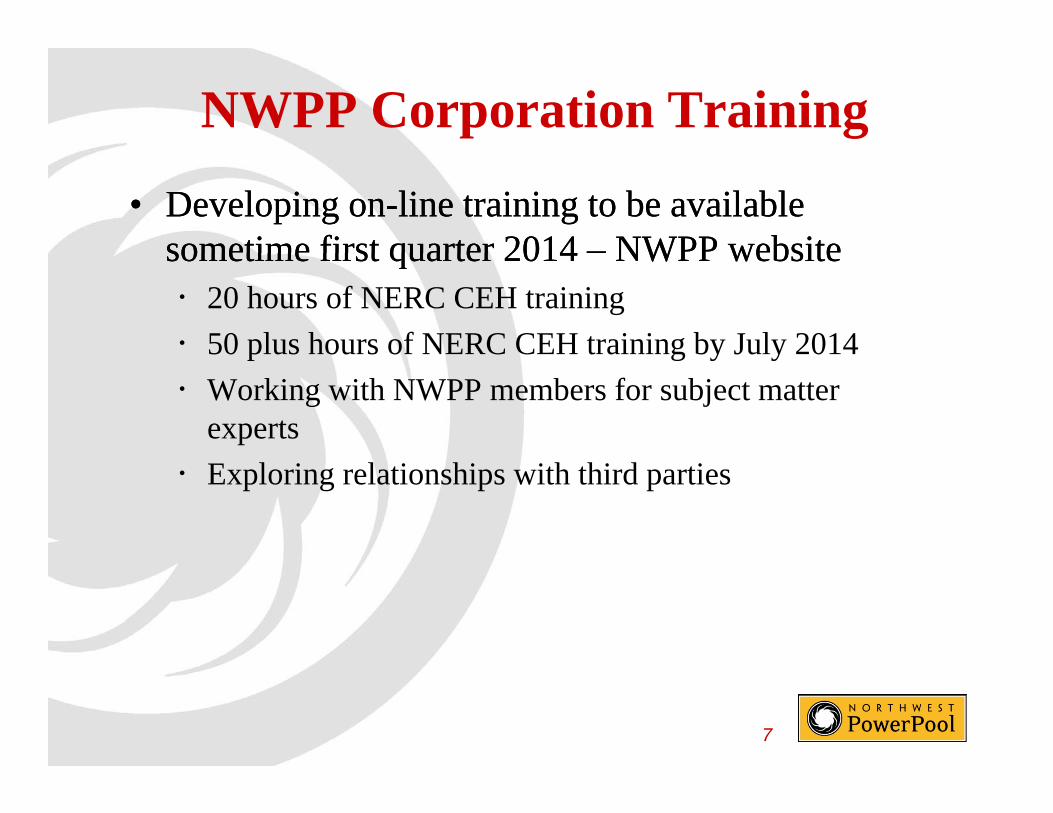
•• Developing onDeveloping on--line training to be available line training to be available sometime first quarter 2014sometime first quarter 2014 –– NWPP websiteNWPP websitesometime first quarter 2014 sometime first quarter 2014 NWPP websiteNWPP website 20 hours of NERC CEH training
50 plus hours of NERC CEH training by July 2014p g y y
Working with NWPP members for subject matter experts
Exploring relationships with third parties
7

NWPP Corporation - Information
Daily Wind data for the NWPP Areawww.nwpp.org/our-resources/NWPP-Reserve-Sharing-Group/Aggregated-NWPP-Geographic-Area-Wind
Geographic NWPP Aggregated Wind Generation and Load 10/6/2013
70,00070000
50,000
60,000
50000
60000
20,000
30,000
40,000
20000
30000
40000
[MW
]
[MW
]
0
10,000
0
10000
1 2 3 4 5 6 7 8 9 10 11 12 13 14 15 16 17 18 19 20 21 22 23 24
Wind Load
8

Northwest Power Pool Corporation
• www.nwpp.org

NORTHWEST POWER POOLNORTHWEST POWER POOL
MembershipMembership
Currently 34Currently 34 Members

NERC/WECC BAs by Sub-regions
Northwest Power Pool Alberta Electric System OperatorAvista CorporationBalancing Authority of Northern CaliforniaBonneville Power Administration
Rocky Mountain Power Pool (RMRG)Public Service Company of ColoradoWestern Area Power Administration – CM
Arizona-New Mexico (SRSG)Bonneville Power AdministrationBritish Columbia Hydro AssociationChelan County PUDDouglas County PUDGrant County PUDIdaho Power CompanyNaturEner Power Watch – Wind Energy
Arizona Public Service CompanyCECD – Arlington ValleyCECD – GriffithCECD – HarquahalaCECD – Panda Gila River El Paso Electric CompanyI i l I i ti Di t i t
gyNaturEner Wind Watch – Wind EnergyNorthwestern EnergyPacifiCorp-EastPacifiCorp-WestPortland General Electric CompanyPuget Sound EnergyS ttl Cit Li htRMPP
Imperial Irrigation DistrictNevada Power CompanyPublic Service Company of New MexicoSalt River ProjectTucson Electric Power CompanyWestern Area Power Administration – LCR
Seattle City LightSierra Pacific Power CompanyTacoma PowerTurlock Irrigation DistrictWestern Area Power Administration – UGPAZNM
RMPP California-MexicoCalifornia Independent System OperatorComision Federal de ElecticidadLos Angeles Dept. of Water and Power
11

Demographics in NWPPElectrical/Geographic Area
8 U.S. States 2 Canadian Provinces Federal, Public, Private, Provincial Ownership International Border (Treaties associated with water) Non Jurisdictional as well as Jurisdictional Non-Jurisdictional as well as Jurisdictional Preference Act – Public Law 88-552 160 Consumer-owned electric utilities 21 Operating Balancing Areas (38 in the Western Interconnection (WI)) 21 Operating Balancing Areas (38 in the Western Interconnection (WI)) ~ 110,000 Megawatts Total Resources (44% WI) ~ 50% Peak load of the WI ~ 50% Energy load of the WIgy Automated Reserve Sharing Procedures Hydro Coordination Hydro Thermal Integration
12
Hydro located on the West (BC, ID, OR, WA) Thermal located on the East (AB, MT, NV, UT, WY)
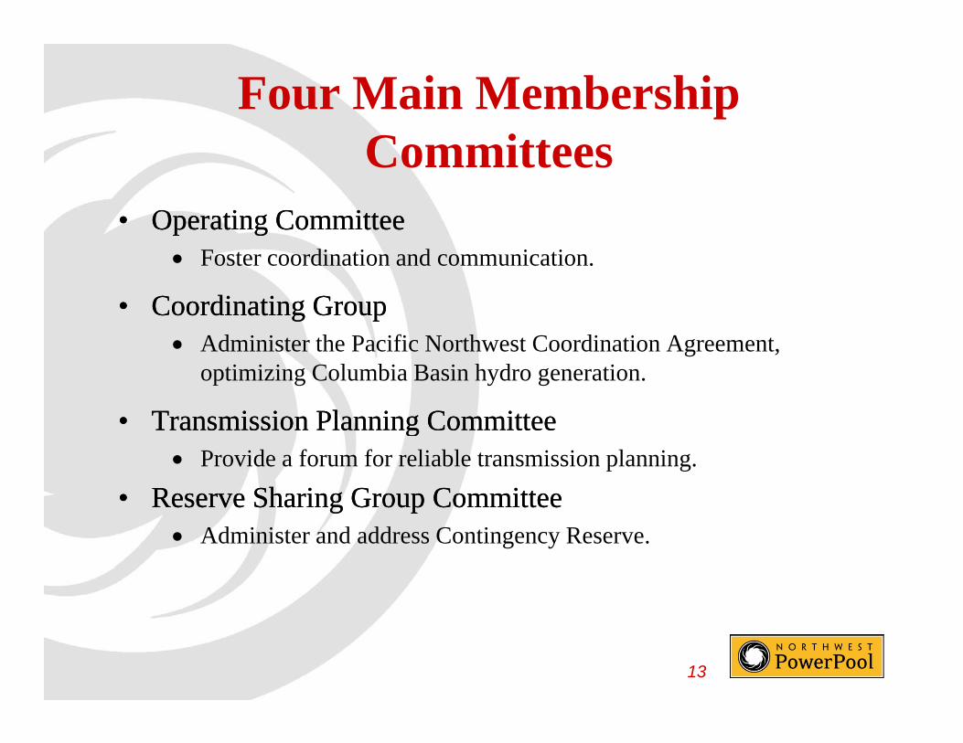
Four Main Membership C ittCommittees
•• Operating CommitteeOperating Committeep gp g Foster coordination and communication.
•• Coordinating Group Coordinating Group Administer the Pacific Northwest Coordination Agreement,
optimizing Columbia Basin hydro generation.
•• Transmission Planning CommitteeTransmission Planning Committee•• Transmission Planning CommitteeTransmission Planning Committee Provide a forum for reliable transmission planning.
•• Reserve Sharing Group CommitteeReserve Sharing Group Committeeg pg p Administer and address Contingency Reserve.
13
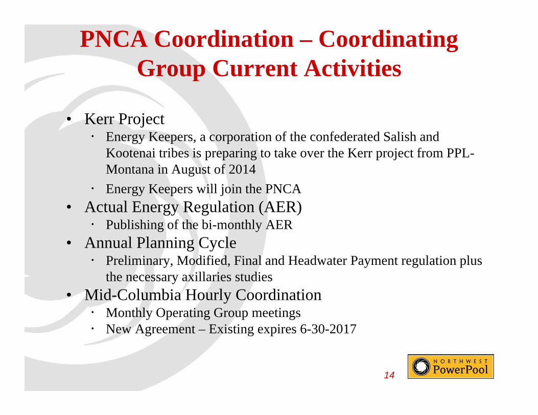
PNCA Coordination – Coordinating Group Current Activitiesp
• Kerr Project Energy Keepers, a corporation of the confederated Salish and
Kootenai tribes is preparing to take over the Kerr project from PPL-Montana in August of 2014
Energy Keepers will join the PNCA
• Actual Energy Regulation (AER) Publishing of the bi-monthly AER
• Annual Planning Cycle Preliminary, Modified, Final and Headwater Payment regulation plus
the necessary axillaries studies
• Mid-Columbia Hourly Coordination Monthly Operating Group meetings New Agreement – Existing expires 6-30-2017
14
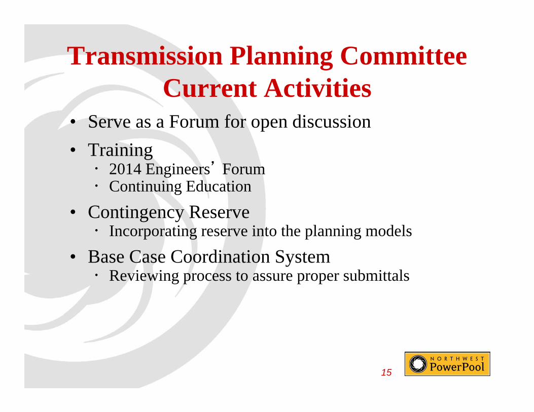
Transmission Planning Committee Current Activities
• Serve as a Forum for open discussionp
• Training 2014 Engineers’ Forum Continuing Education
• Contingency Reserve Incorporating reserve into the planning modelsIncorporating reserve into the planning models
• Base Case Coordination System Reviewing process to assure proper submittalsg p p p
15

Transmission Planning Committee and Operating Committee
• Northwest Operational Planning Study Group (NOPSG)(NOPSG) Seasonal path operating studies
16

Reserve Sharing Group Committee Current ActivitiesCommittee Current Activities
• Unit Contingent TransactionUnit Contingent Transaction Incorporation into the NWPP Reserve Sharing Program
• System Visibility Program expansion incorporating all transmission lines
with the NWPP area• BAL-002-WECC-2BAL 002 WECC 2 Modifying existing documentation to incorporate the new
BAL-002-WECC-2BAL 003• BAL-003 Evaluation frequency response reserve sharing groups
17

Operating Committee Current ActivitiesActivities
• Resolution of Firm-For-The-HourResolution of Firm For The Hour Is it still necessary in today’s world? Antitrust Issues
• Under-frequency Load Shedding Participating on the WECC UFLSRG
• Outage Coordination Process Identifying facilities and timing issues
NWPP T i i M• NWPP Transmission Maps Electronic Version
18

Other OC Services
• NERCNERC Active participation
Coordinated information, discussions, interpretations and presponses
• WECC Coordinated discussions concerning new WECC
Standards, interpretations and responses
19
Other Activities
• Incorporation of new Balancing AuthorityIncorporation of new Balancing Authority Constellation Energy Control and Dispatch Member of both the Operating Committee and whenMember of both the Operating Committee and, when
operational, a member of the Reserve Sharing Group Committee
20
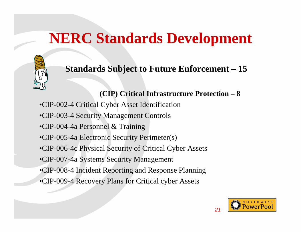
NERC Standards DevelopmentNERC Standards Development
Standards Subject to Future Enforcement – 15j
(CIP) Critical Infrastructure Protection – 8
•CIP-002-4 Critical Cyber Asset Identification
•CIP-003-4 Security Management Controls
•CIP-004-4a Personnel & Training
•CIP-005-4a Electronic Security Perimeter(s)
•CIP-006-4c Physical Security of Critical Cyber Assets
•CIP-007-4a Systems Security Management•CIP-007-4a Systems Security Management
•CIP-008-4 Incident Reporting and Response Planning
•CIP-009-4 Recovery Plans for Critical cyber Assets
21
NERC Standards DevelopmentNERC Standards Development
(EOP) Emergency Preparedness and Operations – 1
•EOP-004-2 Event Reporting
(FAC) Facilities Design, Connections, and Maintenance – 3
•FAC-001-1 Facility Connection Requirements
•FAC-003-2 Transmission Vegetation Management
•FAC-003-3 Transmission Vegetation Managementg g
(PRC) Protection and Control -2
•PRC-004-2.1a Analysis and Mitigation of Transmission Generation P i S Mi iProtection System Mis-operations
•PRC-005-1.1b Transmission and Generation protection System Maintenance and Testing
22
NERC Standards DevelopmentNERC Standards Development
(VAR) Voltage and Reactive – 1(VAR) Voltage and Reactive 1
•VAR-001-3 Voltage and Reactive Control
23

NERC Standards DevelopmentNERC Standards Development
Standards Filed and Pending Regulatory Approval – 54Standards Filed and Pending Regulatory Approval 54
(BAL) Resource and Demand Balancing – 5
•BAL-001-1 Real Power Balancing Control Performance
•BAL-002-1a Disturbance Control Performance
•BAL-002-WECC-2 Contingency Reserve (WECC)BAL 002 WECC 2 Contingency Reserve (WECC)
•BAL-003-1 Frequency Response and Frequency Bias Setting
•BAL-004-WECC-02 Automatic Time Error Correction
24

NERC Standards DevelopmentNERC Standards Development
(CIP) Critical Infrastructure Protection – 10(CIP) Critical Infrastructure Protection 10
•CIP-002-5 BES Cyber System Categorization
•CIP-003-5 Security Management Controls
CIP 004 5 P l & T i i•CIP-004-5 Personnel & Training
•CIP-005-5 Electronic Security Perimeter(s)
•CIP-006-5 Physical Security of Critical Cyber Assets
•CIP-007-5 Systems Security Management
•CIP-008-5 Incident Reporting and Response Planning
•CIP-009-5 Recovery Plans for Critical cyber AssetsC 009 5 ecove y a s o C ca cybe sse s
•CIP-010-1 Configuration Change Management and Vulnerability Assessments
•CIP-011-1 Information Protection
25
•CIP-011-1 Information Protection

NERC Standards DevelopmentNERC Standards Development
(IRO) Interconnection Reliability Operations and Coordination - 4
• IRO-001-3 Responsibilities and Authorities
• IRO-002-3 Analysis Tools
• IRO-005-4 Current Day OperationsIRO-005-4 Current Day Operations
• IRO-014-2 Coordination Among Reliability Coordinators
26
NERC Standards DevelopmentNERC Standards Development
(MOD) Modeling, Data, and Analysis – 9
•MOD-011-0 Maintenance and Distribution of Steady-State Data Requirements and Reporting Procedures
•MOD-013-1 Maintenance and Distribution of Dynamics Data Requirements y qand Reporting Procedures
•MOD-014-0 Development of Steady-State System Models
•MOD-014-0 Development of Dynamics System ModelsMOD 014 0 Development of Dynamics System Models
•MOD-024-1 Verification of Generator Gross and Net Real Power Capability
•MOD-025-01 Verification of Generator Gross and Net Reactive Power CapabilityCapability
•MOD-025-2 Verification and Data Reporting of Generator Real and Reactive Power Capability and Synchronous Condenser Reactive Power Capability
27
Capability

NERC Standards DevelopmentNERC Standards Development
(MOD) Modeling, Data, and Analysis – 9 continue
•MOD-026-1 Verification of Models and Data for Generator Excitation Control System or Plant Volt/Var Control Functions
•MOD-027-1 Verification of Models and Data for Turbine/Govenor and Load Control or Active Power/Frequency control Functions
(PRC) Protection and Control – 11(PRC) Protection and Control 11
•PRC-001-2 System Protection Coordination
•PRC-002-1 Define Regional Disturbance Monitoring and Reporting RequirementsRequirements
•PRC-003-1 Regional Procedure for Analysis of Misoperations of Transmission and Generation and Protection Systems
PRC 005 2 P i M i
28
•PRC-005-2 Protection system Maintenance

NERC Standards DevelopmentNERC Standards Development
(PRC) Protection and Control – 11 continue
•PRC-012-0 Special Protection System Review Procedure
•PRC-013-0 Special Protection System Database
•PRC-014-0 Special Protection System AssessmentPRC-014-0 Special Protection System Assessment
•PRC-019-1 Coordination of Generating Unit or Plan Capabilities, Voltage Regulating Controls, and Protection
•PRC 020 1 Under Voltage Load Shedding Program Database•PRC-020-1 Under Voltage Load Shedding Program Database
•PRC-024-1 Generator Frequency and Voltage Protective Relay Settings
•PRC-025-1 Generator Relay Loadability
29

NERC Standards DevelopmentNERC Standards Development
(TOP) Transmission Operations – 4
•TOP-001-2 Transmission Operations
•TOP-002-3 Operations Planning
•TOP-003-2 Operational Reliability DataTOP-003-2 Operational Reliability Data
•TOP-006-3 Monitoring System Conditions
( ) i i i 10(TPL) Transmission Planning – 10
•TPL-001-2 Transmission System Planning Performance Requirements
•TPL-001-3 System Performance Under Normal (No Contingency) Conditions (Category A)
•TPL-001-4 Transmission System Planning Requirements
•TPL-002-2b System Performance Following Loss of a Single Bulk Electric
30
y g gSystem Element (Category B)
NERC Standards DevelopmentNERC Standards Development(TPL) Transmission Planning – 10 continue
•TPL 003 2a System Performance Following Loss of Two or More Bulk•TPL-003-2a System Performance Following Loss of Two or More Bulk Electric System Elements (Category C)
•TPL-003-2b System Performance Following Loss of Two or More Bulk Electric System Elements (Category C)Electric System Elements (Category C)
•TPL-004-2 System Performance Following Extreme Events Resulting in the Loss of Two or More Bulk Electric System Elements (Category D)
TPL 004 2 S t P f F ll i E t E t R lti i•TPL-004-2a System Performance Following Extreme Events Resulting in the Loss of Two or More Bulk Electric System Elements (Category D)
•TPL-005-0 Regional and Interregional Self Assessment Reliability Reports
•TPL-006-0 Data From the Regional Reliability Organization Needed to Assess Reliability
31

NERC Standards DevelopmentNERC Standards DevelopmentStandards Filed and Pending Regulatory Filing - 8
(BAL) Resource and Demand Balancing – 1
•BAL-001-2 Real Power Balancing Control Performance
(CIP) Critical Infrastructure Protection – 1
•CIP-002-3b Critical Cyber Asset Identification
(COM) Communications – 3
•COM-001-2 Communications
•COM-002-2a Communication and Coordination
•COM-002-3 Communication and Coordination
32
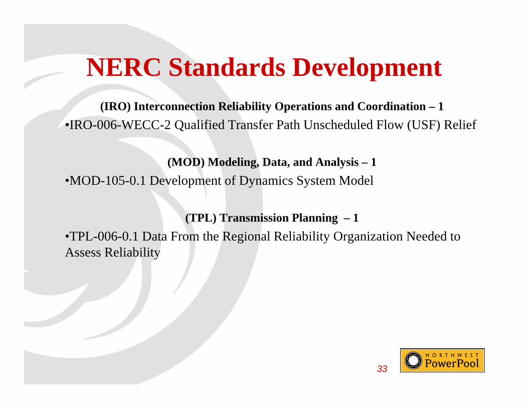
NERC Standards DevelopmentNERC Standards Development(IRO) Interconnection Reliability Operations and Coordination – 1
•IRO-006-WECC-2 Qualified Transfer Path Unscheduled Flow (USF) ReliefIRO 006 WECC 2 Qualified Transfer Path Unscheduled Flow (USF) Relief
(MOD) Modeling, Data, and Analysis – 1
MOD 105 0 1 D l t f D i S t M d l•MOD-105-0.1 Development of Dynamics System Model
(TPL) Transmission Planning – 1
•TPL-006-0.1 Data From the Regional Reliability Organization Needed to Assess Reliability
33

NERC Standards DevelopmentNERC Standards Development• February 12, 2013 - NERC submits a petition of the North American
Electric Reliability Corporation seeking approval of the proposedElectric Reliability Corporation seeking approval of the proposed interpretation of BAL-002-1.
Status – FERC “proposes to remand NERC’s interpretation of BAL–002–1 because it fails to comport with the Commission approved002 1 because it fails to comport with the Commission approved requirement that interpretations can only clarify, not change, a Reliability Standard.” Sixteen entities filed comments. Now awaiting FERC response.
• February 26, 2013 - NERC submits a Joint Petition of the North American Electric Reliability Corporation and Western Electricity Coordinating Council for Approval of WECC Regional Reliability Standard BAL-004-WECC-02 — Automatic Time Error Correction. BAs will be allowed to use ATEC ACE as their Reporting ACE and limits accumulations of Primary Inadvertent Interchange.
34
Status – awaiting FERC response.

NERC Standards DevelopmentNERC Standards Development• March 29, 2013 - NERC submits a petition for Approval of Reliability
Standard BAL-003-1 – Frequency Response and Frequency BiasStandard BAL 003 1 Frequency Response and Frequency Bias Setting. The proposed standard ensures that each of the Interconnections have sufficient Frequency Response to guard against underfrequency load shedding (“UFLS”) due to a loss of resources in that Interconnection. g ( )
Status - FERC responded with a NOPR. Industry is commenting.
• April 12, 2013 - NERC submits a Joint Petition of the North American Electric Reliability Corporation and Western Electricity CoordinatingElectric Reliability Corporation and Western Electricity Coordinating Council for Approval of WECC Regional Reliability Standard BAL-002-WECC-2, Contingency Reserve.
Status – FERC responded with a NOPR. WECC has commented. S a us C espo ded w a NO . W CC as co e ed.
35

NERC Standards DevelopmentNERC Standards Development• April 16, 2013 - NERC submits a Petition for Approval of revised
Reliability Standard IRO-005-4 – Current Day Operations. RCReliability Standard IRO 005 4 Current Day Operations. RC Monitoring of CPS and DCS has been removed.
Status - awaiting FERC response.
O S b 6 2013 NERC d BAL 002 2 C i R• On September 6, 2013 NERC posted BAL-002-2, Contingency Reserve for Recovery from a Balancing Contingency Event, for a non-binding poll. The ballot period was extended one additional day to achieve a quorumquorum.
Status – The ballot only achieved 58.23% approval. The drafting team is responding to comments and revising their proposal.
36

NERC Standards DevelopmentNERC Standards Development
• Challenges – The world continues to evolve ~ 80 Standards to beChallenges The world continues to evolve 80 Standards to be implemented with changes.
• Technology Changes – As the industry embraces new technology to timely provide more information designed to improve reliability the.timely provide more information designed to improve reliability, the industry continues to evolve.
• Costs – As the industry evolves, the costs continues to increase
37

NERC Standards DevelopmentNERC Standards Development
C l P i d U d diCalm, Patience, and Understanding
We must all get along
38

QUESTIONS?QUESTIONS?

Northwest Power Pool Corporation
• www.nwpp.org

NWPP NWPP AfterAfter--thethe--FactFact –– SystemSystemAfterAfter--thethe--Fact Fact System System
Schedulers MeetingSchedulers MeetingQ iQ i AAQuiz Quiz -- AnswersAnswers
2013

1 Li t t l t 2 t f i th NWPP1. List at least 2 types of service the NWPP Corporation Provides:
• Training,
• Programs (Support of Committees)Programs (Support of Committees)
• Reporting (RSG)
C• Corporate (corporate management services to the industry, specializing in efficiently assisting power utility organizations in successfully accomplishing their goals, objectives, and obligations.)
2
2 D fi h A f h f h2. Define the Acronym for each of the following: EIWG, IWG, & ESWG
• (EIWG) E-Tagging Issues Work Group
• (IWG) Interchange Criteria Work Group
• (ESWG) Electronic Scheduling Work Group
3

3. What was the purpose the Joint Guidance Committee’s Order 764 Task Force?
• The purpose of the task force was to• The purpose of the task force was to assess the impacts of 15 minute scheduling in the Westernscheduling in the Western Interconnection and how identified impacts affect the reliability andimpacts affect the reliability and commercial activities of WECC
4
4. Start-Stop dates are important to the EIR because:
a) These dates determine when the object shall be excluded from active publication.
b) These dates determine when the object is included in active participation.
c) Some parent start and stop dates must be “within’ the
b) Th d t d t i h th bj t
c) Some parent start and stop dates must be within the child(rens) start and stop dates.
b) These dates determine when the object is included in active participation.
5
5. Define the acronym GMD, and in the5. Define the acronym GMD, and in the world of electricity and why is it a concern?concern?
• Geomagnetic Disturbance
• This kind of disturbance poses risk to BES causing voltage stability problems and etc…
6

6 Wh t th NWPP i iti ll6. What year was the NWPP initially formed?
a) 1934b) 1952 )c) 1995d) 1941
d) 1941
)
d) 1941
7

7. Some common Reasons for use of ATF Tags are:
a) Missing or incorrect Point of Receipt or Point of Deliveryy
b) Curtailment Issuesc) Incorrect generator on tag) g gd) a, b, & ce) a & b only
d) b &
) yf) None of the above?
d) a, b, & c8

8. True or False – BPA’s new ASC will be located the Munro Scheduling Center.
True – BPA’s new ASC will be located in Spokane, WA.
9

9. What are the demographics of the NWPP – where does it operate? List the number of States ______ and number of Canadian provinces_______
• 8 U.S. States
• 2 Canadian Provinces
10
10. Solve the word jumbles just below:
• CWEC tnciirBfautoCWEC tnciirBfauto• uehddcelUsln wlfo• esonigoctn aneemtngmaesonigoctn aneemtngma
• WECC Bifurcation f
• Unscheduled flow
• Congestion management• Congestion management
11

11 Wh i th t h d l d P tl d11. When is the next scheduled Portland Timbers next game and is it at home or
?away?
10.19.2013 @ 7:30 p.m. - Home
12

12 Li h f i i f h12. List the four main committees of the NWPP.
• Coordinating Group – some would say PNCAsay PNCA
• Operating Committee
• Reserve Sharing Group Committee
• Transmission Planning Committeeg
13
Bonneville Power AdministrationS l M ti E tSolar Magnetic Events
GMD/GIC Overview
Richard Becker
Manager Substation EngineeringManager, Substation Engineering
October 16, 2013
NWPP After-the-Fact andNWPP After the Fact and
System Scheduler Meeting

Overview1. What is a Geomagnetic Disturbance (GMD) a s a Geo ag e c s u ba ce (G )
2. What are the concerns
3 What is being done to better understand3. What is being done to better understand effects and impacts
4. How to manage adverse impacts4. How to manage adverse impacts
5. What study and operational management tools are available and on the horizon
6. Technical limitations for where we are today
22
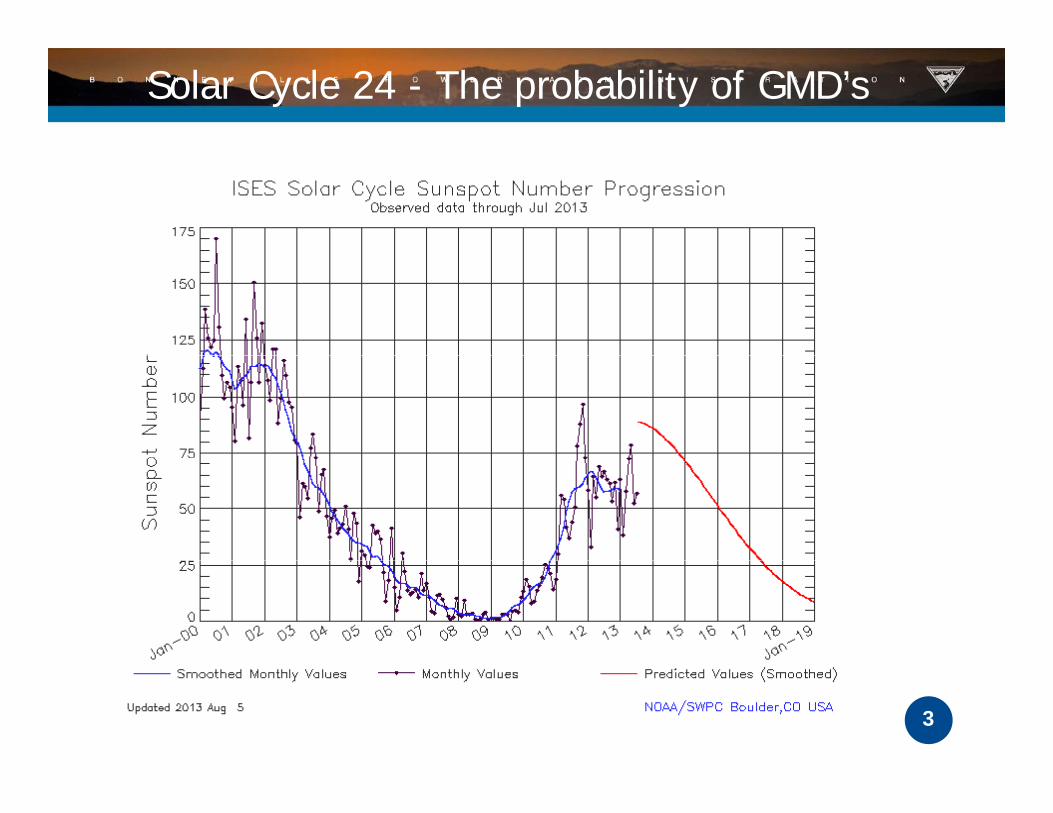
Solar Cycle 24 - The probability of GMD’s
3
History of Cycles
Take note
18591921
859
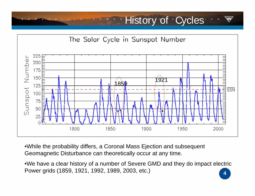
•While the probability differs, a Coronal Mass Ejection and subsequent Geomagnetic Disturbance can theoretically occur at any time.
4
•We have a clear history of a number of Severe GMD and they do impact electric Power grids (1859, 1921, 1992, 1989, 2003, etc.)

Uncertainty in Prediction
5
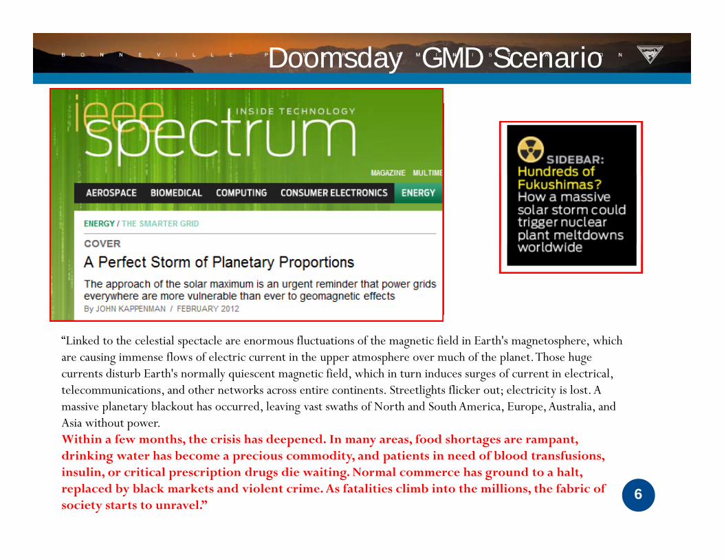
Doomsday GMD Scenario
“Linked to the celestial spectacle are enormous fluctuations of the magnetic field in Earth's magnetosphere, which are causing immense flows of electric current in the upper atmosphere over much of the planet. Those huge currents disturb Earth's normally quiescent magnetic field, which in turn induces surges of current in electrical,
l d h k l h fl k l l telecommunications, and other networks across entire continents. Streetlights flicker out; electricity is lost. A massive planetary blackout has occurred, leaving vast swaths of North and South America, Europe, Australia, and Asia without power.Within a few months, the crisis has deepened. In many areas, food shortages are rampant, drinking water has become a precious commodity and patients in need of blood transfusions
6
drinking water has become a precious commodity, and patients in need of blood transfusions, insulin, or critical prescription drugs die waiting. Normal commerce has ground to a halt, replaced by black markets and violent crime. As fatalities climb into the millions, the fabric of society starts to unravel.”

US “Doomsday” Scenario
According to the scenario..•Based on a projected 5,000 nT/min storm, a large numbers of EHV transformers
7
will fail• Since transformers are custom-built and not sourced domestically (This is changing), recovery could take years

Coronal Mass Ejections
Magnetosphere
Energetic Charged Particles
IonosphereIonosphereHeliosphere
8
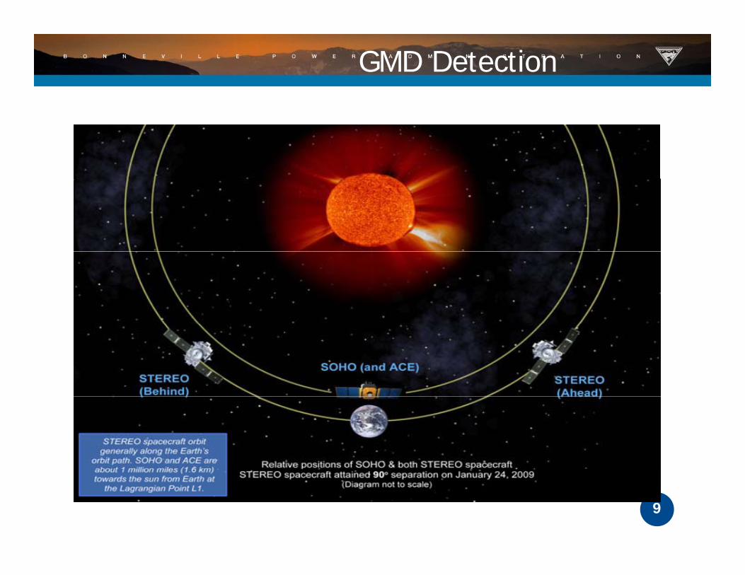
GMD Detection
9

NASA Solar Wind Prediction
10Source: WSA-Enil Solar Wind Tool

A Recent “Near Miss”
On July 23rd 2012, a powerful event d h Th i occurred on the sun. The eruption
however, was on the far side of the sun; consequently, we are not expecting any geomagnetic activity It is likely that if geomagnetic activity. It is likely that if this event had occurred ~10 days earlier when the sunspot cluster was facing Earth, we would have initiated the Earth, we would have initiated the NERC/RC telecon for a likely extreme geomagnetic storm. The flare was huge and the CME was very fast. The CME yimpacted the STEREO spacecraft ~19-20 hours after the eruption on the sun. That would put it in the Carrington
11
1859 (17.6 hrs), Halloween 2003
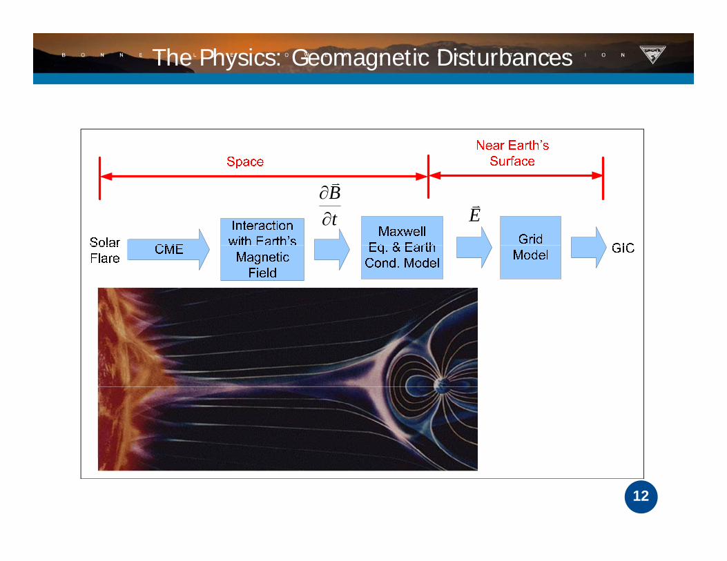
The Physics: Geomagnetic Disturbances
t
B
E
12

Induced GIC Flow from Electric Field
13

What are the risks to operation of the bulk power system from a strong GMD?
• The most significant issue for system operators to overcome a severe GMD event is to maintain voltage stability.
• As transformers absorb high levels of reactive power,As transformers absorb high levels of reactive power, protection and control systems may trip supporting reactive equipment due to the harmonic distortion of waveformswaveforms.
• In addition, maintaining the health of operating bulk power system assets during a geomagnetic storm is a key consideration for asset managers.
• There is also the indication that GIC could lead to failure of Transformer Banks in unusual circumstances.
14
of Transformer Banks in unusual circumstances.

What transformers are at risk from a GMD?
The magnitude, frequency, and duration of GIC, as well as the geology and transformer design are key considerations in determining the amount of heating that develops in theamount of heating that develops in the windings and structural parts of a transformer.
The effect of this heating on the condition, performance, and insulation life of the transformer is also a function of a transformer’s design and operational loading during a GMD event
15
event.

Continued
Some older transformer designs are more at risk f d h dfor experiencing increased heating and VAr consumption than newer designs.
Additionally, transformers that have high water content and high dissolved gasses and thosecontent and high dissolved gasses and those nearing their dielectric end‐of‐life may also have a risk of failure.
16
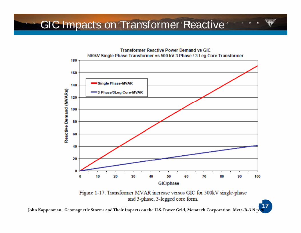
GIC Impacts on Transformer Reactive
17John Kappenman, Geomagnetic Storms and Their Impacts on the U.S. Power Grid, Metatech Corporation Meta-R-319 p 20

Thermal Stress from Half Cycle Saturation
Thermal models are needed to know if a transformer is operating beyond thermal capability, and work is underway to develop models that translate GIC winding current to amodels that translate GIC winding current to a hot spot temperature.
18
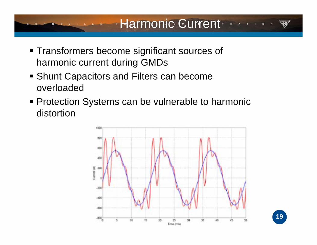
Harmonic Current
Transformers become significant sources of harmonic current during GMDs
Shunt Capacitors and Filters can become Shunt Capacitors and Filters can become overloaded
Protection Systems can be vulnerable to harmonic distortion
19
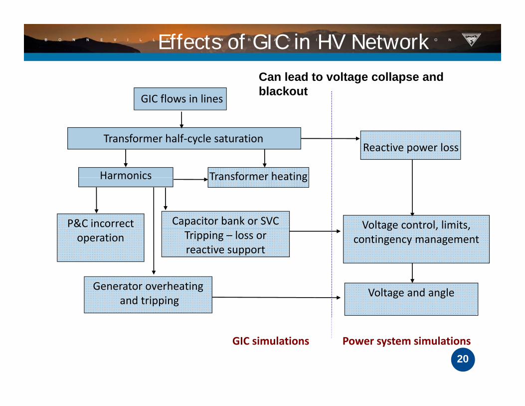
Effects of GIC in HV NetworkCan lead to voltage collapse andCan lead to voltage collapse and blackoutGIC flows in lines
Transformer half‐cycle saturationReactive power loss
Transformer heatingHarmonics
P&C incorrect Voltage control, limits,Capacitor bank or SVC
Transformer heatingHarmonics
operationg , ,
contingency managementTripping – loss or reactive support
Generator overheatingand tripping
Voltage and angle
stability
20GIC simulations Power system simulations

GMD Probability >300nT/min
21

NERC GMD Task Force Report
• Most likely result from a severe GMD isMajor Most likely result from a severe GMD is the need to maintain voltage stability
Major Conclusion
• System operators and planners need tools to maintain reactive power supply
Major Conclusion tools to maintain reactive power supplyConclusion
f b d d• Some transformers may be damaged or lose remaining life, depending on design and current health
Major Conclusion
22

Severity Indexes
Solar Activity A Index Level K Index Level
Quiet A Index <7, Usually no K‐indices >2
Unsettled 7 < A Index < 15, Usually no K‐indices > 3
Local
Active 15 < A Index < 30, A few K‐indices of 4
Minor Geomagnetic Storm 30 < A Index < 50, K‐indices mostly 4 and 5
Major Geomagnetic Storm 50 < A Index <100 K‐indices mostly 5 and 6
Severe Geomagnetic Storm A Index>100 K‐indices 7 or greater
Kp Index NOAA Space Weather Scale Geomagnetic Storm LevelsGlobal
Kp=5 G1 (Minor)
Kp=6 G2 (Moderate)
Kp=7 G3 (Strong)
23Kp=8 G4 (Severe)
Kp=9 G5 (Extreme)

What Happens in case of a GMD?
IRO-005-3.1a R3. Each Reliability Coordinator shall ensure its Transmission Operators and Balancing Authorities are aware of Geo-Magnetic Disturbance (GMD) forecast information and assist as needed in the development of any required response plans. This will typically happen at a K7
24
q p p yp y ppindex level.
Geomagnetic Disturbance Mitigation
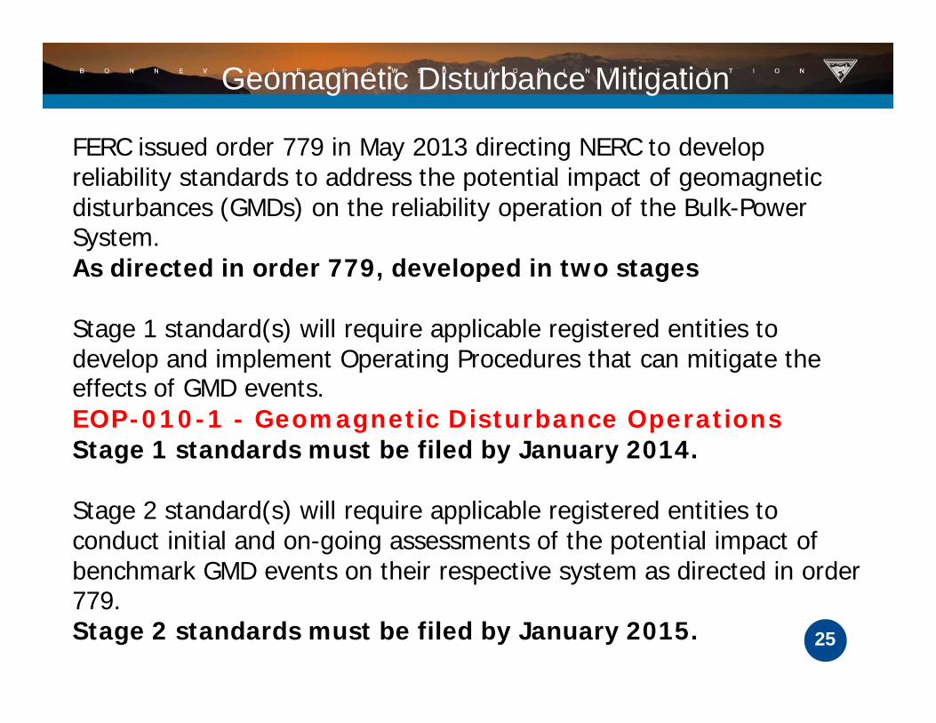
FERC issued order 779 in May 2013 directing NERC to develop reliability standards to address the potential impact of geomagnetic disturbances (GMDs) on the reliability operation of the Bulk-Power System.As directed in order 779, developed in two stages
Stage 1 standard(s) will require applicable registered entities to develop and implement Operating Procedures that can mitigate the effects of GMD events.EOP-010-1 - Geomagnetic Disturbance Operations Stage 1 standards must be filed by January 2014.
Stage 2 standard(s) will require applicable registered entities to conduct initial and on-going assessments of the potential impact of benchmark GMD events on their respective system as directed in order
25
779.Stage 2 standards must be filed by January 2015.

NERC Alert: Anticipating GMD
Actions to be considered : 1. Increase import capability:
Discontinue non critical maintenance work and restore• Discontinue non-critical maintenance work and restore out-of-service transmission lines, wherever possible. • Evaluate postponing/rescheduling planned outage and maintenance activities. Avoid taking transmission lines out of service unless reliability affects of the line outage has been evaluated.been evaluated.
2. The Reliability Coordinator may instruct Generator Operators to increase real and reactive reserves to preserveOperators to increase real and reactive reserves to preserve system integrity during a strong GMD event by performing such actions as: Reducing generator loading
26
NERC Alert: Anticipating
3. Transmission Operators and Generator Operators should increase situational awareness and enhance surveillance procedures Reliabilityand enhance surveillance procedures. Reliability Coordinators should be informed of all actions such as:• Unusual voltage and/or MVAr variations and unusual
temperature rise are detected on transformers and GSU’s.
• Abnormal noise and increased dissolved gas on transformers, where monitoring capability exists.
• Trips by protection or unusual faults that are detected• Trips by protection or unusual faults that are detected in shunt capacitor banks and static VAR compensators.
27
Real-Time Operations
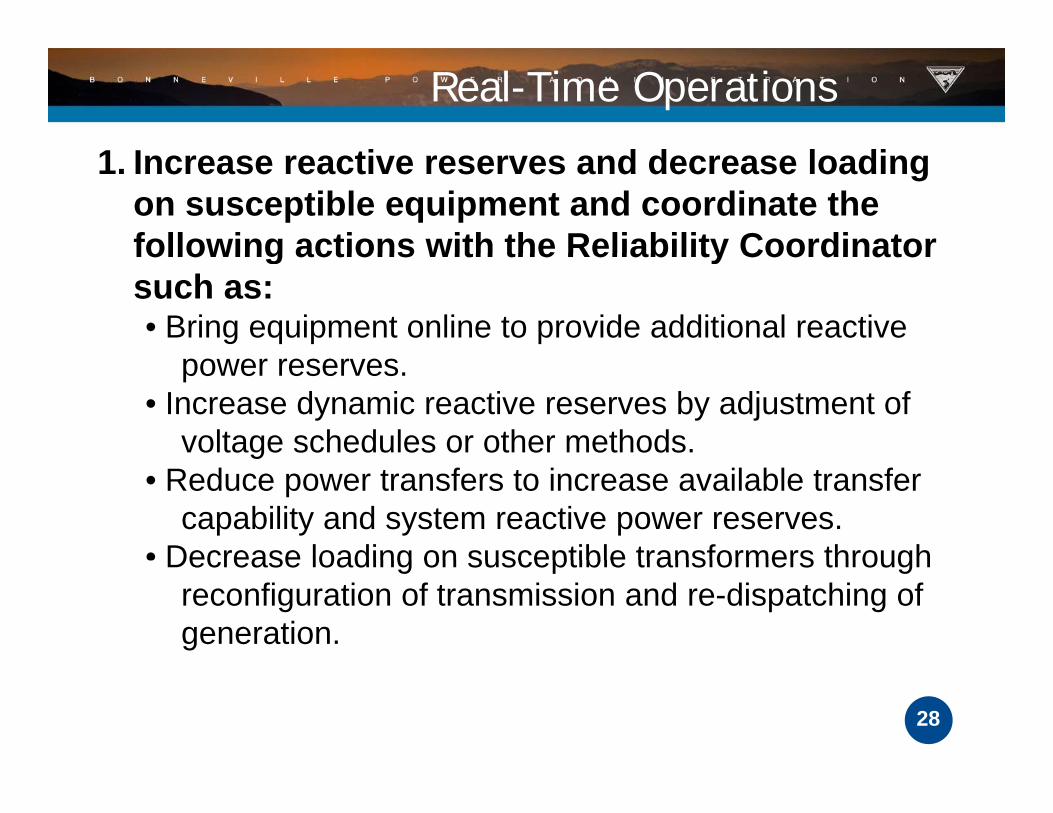
1 I ti d d l di1. Increase reactive reserves and decrease loading on susceptible equipment and coordinate the following actions with the Reliability Coordinatorfollowing actions with the Reliability Coordinator such as:• Bring equipment online to provide additional reactive
power reserves. • Increase dynamic reactive reserves by adjustment of
voltage schedules or other methods.g• Reduce power transfers to increase available transfer
capability and system reactive power reserves. • Decrease loading on susceptible transformers through Decrease loading on susceptible transformers through
reconfiguration of transmission and re-dispatching of generation.
28

Real Time2 I tt ti t it ti d2. Increase attention to situation awareness and coordinate information and actions with Reliability Coordinator such as: • Reduce power output at susceptible generator stations if erratic reactive power output from generators or excess reactive power consumptiongenerators or excess reactive power consumption by generator step-up transformers is detected.
• Remove transmission equipment from service if excessive GIC is measured or unusual equipment behavior is experienced and the system affects ofbehavior is experienced and the system affects of the equipment outage has been evaluated.
29

BPA Actions to Assess and Prepare
Assure we have appropriate proceduresEstimate vulnerability of system equipment and protection schemes to GIC. (Model and p (simulate). Increase visibility of GIC on the system (RealIncrease visibility of GIC on the system (Real time measurement)Assure we have system equipment andAssure we have system equipment and protection schemes to mitigate vulnerability
30
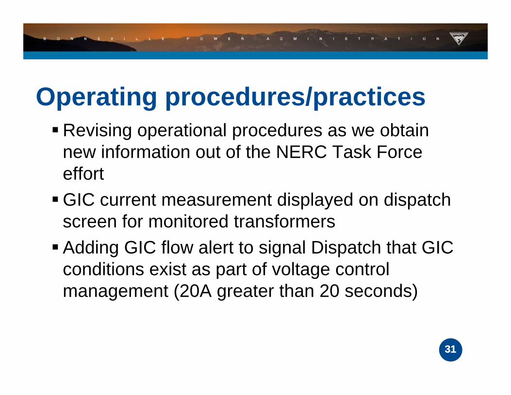
Operating procedures/practicesRevising operational procedures as we obtain
new information out of the NERC Task Force efforteffort
GIC current measurement displayed on dispatch screen for monitored transformersscreen for monitored transformers
Adding GIC flow alert to signal Dispatch that GIC conditions exist as part of voltage controlconditions exist as part of voltage control management (20A greater than 20 seconds)
3131

Transformer MonitoringBPA is replacing our first vintage neutral current
monitors with measurement that also includes:• DC amps • VARS
H i• Harmonics • Tank wall vibration
3232

New GIC monitorNew GIC monitor
3333
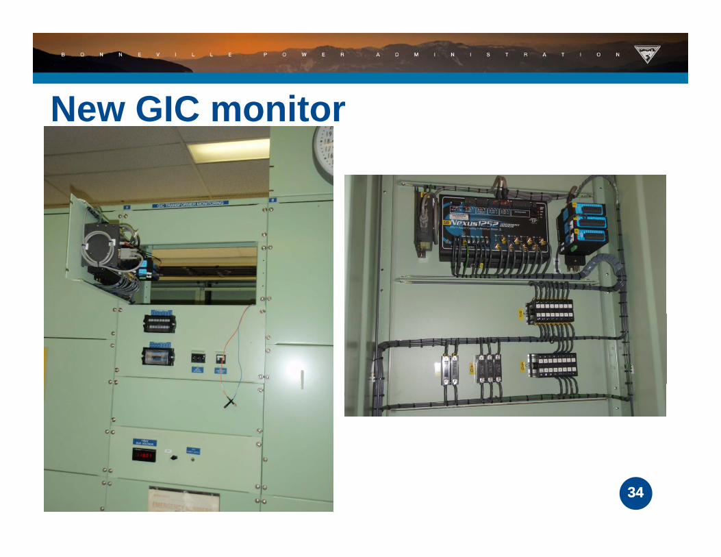
New GIC monitorNew GIC monitor
3434

SC f CSCADA – Autotransformer Neutral Amps DC
3535

GIC Modeling and StudiesContracted a GIC study through a commercial
software vendor 115 kV to 500 kV
This partnership has helped obtain resistive modeling data from neighboring utilitiesg g g
First VAR demand sensitivity study of grid completed September 2013
3636
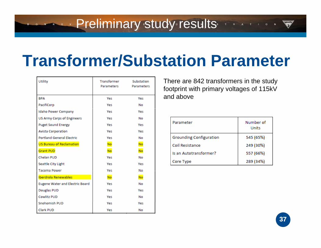
Preliminary study results
Transformer/Substation ParameterThere are 842 transformers in the study footprint with primary voltages of 115kV and above
3737

Uniform Field Modeling Results1V/k 75 d i t ti1V/km, 75 degree orientation
Including 115kV
excluding 115kV difference
GIC 3 phase Transformer MVAR Losses 1335 1265 70 or 5 24%GIC 3 phase Transformer MVAR Losses 1335 1265 70 or 5.24%
3838

Uniform Field Modeling Results Apply Neutral Blocking
3939

Real time SimulatorsWorking on modeling with NRCan simulator to
compare performance against GIC monitor datap p g
Looking to use study models and simulators to perform sensitivity studies to determine locations p yof high GIC flow to pre-inform system operators of potential trouble
Industry needs a real time tool in addition to pre-worked scenario studies of the network
4040
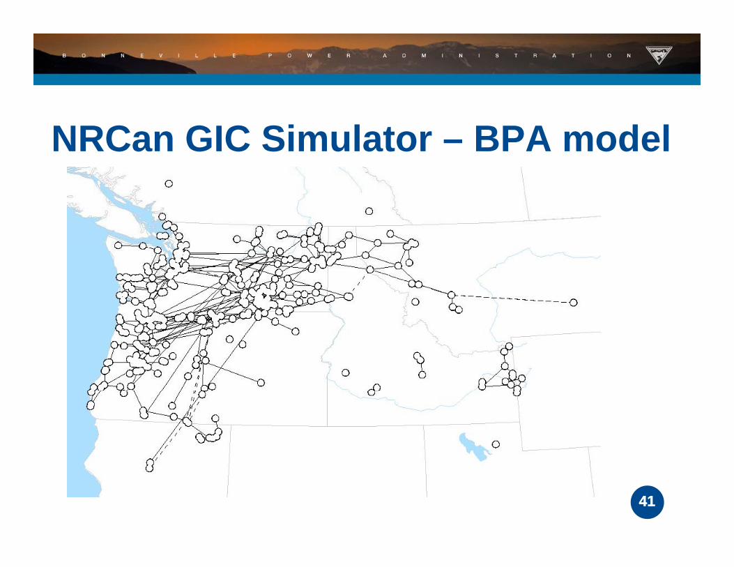
NRCan GIC Simulator – BPA model
4141
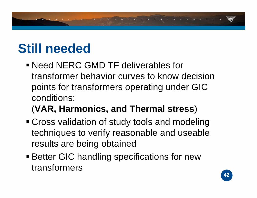
Still neededNeed NERC GMD TF deliverables for
transformer behavior curves to know decision points for transformers operating under GICpoints for transformers operating under GIC conditions: (VAR, Harmonics, and Thermal stress)(VAR, Harmonics, and Thermal stress)
Cross validation of study tools and modeling techniques to verify reasonable and useable q yresults are being obtained
Better GIC handling specifications for new
42
g ptransformers
42
INFORMATION
NERC GMD TF 2 Deliverables http://www.nerc.com/comm/PC/Geomagnetic%20
Disturbance%20Task%20Force%20GMDTF%20DL/GMD Phase 2 Project Plan APPROVED pDL/GMD_Phase_2_Project_Plan_APPROVED.pdf
43

Other Information Sources
http://www.nerc.com/comm/PC/Pages/Geomagnetic-Disturbance-Task-Force-magnetic-Disturbance-Task-Force-(GMDTF)-2013.aspx
http://www geomag nrcan gc ca/lab/defaulthttp://www.geomag.nrcan.gc.ca/lab/default-eng.php
htt // i / b t t /P /P dhttp://www.epri.com/abstracts/Pages/ProductAbstract.aspx?ProductId=000000000001026425026425
44

http://www.nerc.com/files/2012GMD.pdf
http://www nerc com/comm/PC/Pages/Geohttp://www.nerc.com/comm/PC/Pages/Geomagnetic%20Disturbance%20Task%20Force%20(GMDTF)/Geomagneticce%20(GMDTF)/Geomagnetic-Disturbance-Task-Force-GMDTF.aspx
htt // / /St d/P /P jhttp://www.nerc.com/pa/Stand/Pages/Project-2013-03-Geomagnetic-Disturbance-Miti tiMitigation.aspx
45

ATFWG ReportATFWG ReportNWPP M tiNWPP Meeting
October 15 & 16, 2013
P tl d ORPortland, OR
Amy Lubick - NWMT
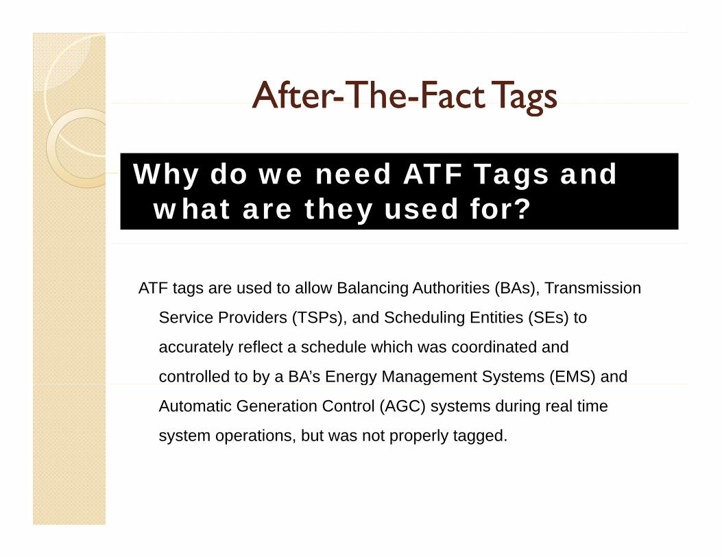
AfterAfter--TheThe--Fact TagsFact TagsAfterAfter TheThe Fact TagsFact Tags
Why do we need ATF Tags and Why do we need ATF Tags and what are they used for?
ATF tags are used to allow Balancing Authorities (BAs), Transmission
S i P id (TSP ) d S h d li E titi (SE ) tService Providers (TSPs), and Scheduling Entities (SEs) to
accurately reflect a schedule which was coordinated and
controlled to by a BA’s Energy Management Systems (EMS) and y gy g y ( )
Automatic Generation Control (AGC) systems during real time
system operations, but was not properly tagged.

AfterAfter--TheThe--Fact TagsFact TagsAfterAfter TheThe Fact TagsFact Tags
Common Reasons Used to Create
Missing or incorrectly used BA TP or SE
ATF Tags: Missing or incorrectly used BA, TP, or SE
Curtailment Issues
Incorrect generator on tag
Missing or incorrect Point of Receipt or Point of Delivery t( )segment(s)
Incorrect transmission path on tag versus what was purchased on the TSR (Transmission Service Reservation) ( )
Correction of losses

AfterAfter--TheThe--Fact TagsFact TagsMore on ATF Tags:
Can be created up to 168 hours (one week) after the start time and are processed per NAESB e-Tag Specifications.
Prior to submitting - all involved parties need to agree upon the requestedPrior to submitting all involved parties need to agree upon the requested changes.
◦ Changes can only be made to correct the tag to properly reflect the coordinated and controlled to system operations at the time.
Lead entity shall coordinate with all parties involved to make sure all agree to the start time, stop time, MWhs, integrated values if necessary, reservation numbers, etc.
In the comment field, note that this is an ATF tag replacing an original tag.
◦ For example, in naming the ATF tag, original tag name ABC1234 would be replaced by ATF tag ATF1234.
Once the ATF tag is submitted, all involved parties must be informed that the tag is ready for approval and the new tag number should be referenced.

AfterAfter--TheThe--Fact TagsFact TagsAfterAfter TheThe Fact TagsFact TagsCommon Process Flow for ATF Tags
d/ WECC S h d l R t F Call and/or email all parties involved on the tag when an ATF tag is needed
and gain agreement to proceed.
and/or WECC Schedule Request Form:
g g p Coordinate changes needed within the timeframe for processing/submitting
the ATF tag. Route WECC Schedule Request Change Form to all parties for signatures. Submit the Schedule Change Request Form to WECC and copy all parties g q py p
involved. After WECC responds that the changes have been completed, all parties
should verify that the changes were made properly in the WECC Interchange Tool (WIT). S b i h ATF i f ll i l d i h h i f l Submit the ATF tag, inform all involved parties that the tag is out for approval and reference the new tag number.
Each entity should update its in-house scheduling software to reflect the changes (adjust or zero MW on the original tag schedule) and if necessary verify that the resultant Net Schedule Interchange matches with WIT for thatverify that the resultant Net Schedule Interchange matches with WIT for that particular hour.

Tracking ATF Tags Tracking ATF Tags Tracking ATF Tags Tracking ATF Tags
Continue to track ATF tags in 2013.
As of mid August there were a total of 43 ATF tags and/or WIT hWIT changes.

ATF Manual GuidelineATF Manual GuidelineATF Manual GuidelineATF Manual Guideline
S b t bli h d t i d Subgroup established to review and revise document.
Six (6) webinar meetings held in late 2012 - early 2013 (all posted &2012 early 2013 (all posted & notifications sent).
Revised document has been reviewed by WECC Technical Writer (April y (2013).

ATF Manual GuidelineATF Manual GuidelineATF Manual GuidelineATF Manual Guideline Posted for 30 day comment period
(6/28 7/28)(6/28 – 7/28).
Received comments from one party Received comments from one party.
Webinar meeting posted (9/19) and Webinar meeting posted (9/19) and held last week (10/9) to respond to the comments received.
Anticipate approval of document at January 2014 ISAS meetingJanuary 2014 ISAS meeting.
DOUBLETREE BY HILTON DOUBLETREE BY HILTON –– LLOYD DISTRICTLLOYD DISTRICT1000 NE MULTNOMAH, PORTLAND, OR 972321000 NE MULTNOMAH, PORTLAND, OR 97232

PURPOSE OF THE ALTERNATE SCHEDULING CENTER IS TO PROVIDE CRITICAL BACKUP AND RECOVERY CAPABILITIES TO ENSURE BPA’S ABILITY TO MAINTAIN OPERATIONS IN CASE OF ANMAINTAIN OPERATIONS IN CASE OF AN EARTHQUAKE OR OTHER EMERGENCY IMPACTING THE ENTIRE PORTLAND / VANCOUVER METRO AREAAREA.
BPA’S ALTERNATE SCHEDULING CENTER IS BPA S ALTERNATE SCHEDULING CENTER IS FORMALLY KNOWN AS THE MUNRO SCHEDULINGCENTER (MSC).

REQUIRED BY FEDERAL CONTINUITY DIRECTIVESI & II ISSUED BY DEPT OF HOMELAND SECURITYI & II ISSUED BY DEPT OF HOMELAND SECURITY
DIRECTIVES REQUIRE FEDERAL AGENCIES TO MAINTAIN MISSION ESSENTIAL FUNCTIONS DURING PERIODS OF INTERRUPTIONPERIODS OF INTERRUPTION

NATURAL DISASTERS - (EARTHQUAKE, FLOODS, etc)
PANDEMICS - DOES NOT THREATEN INFRASTRUCTURE, BUT DEGRADES HUMAN RESOURCES DUE TO ILLNESS DEATHRESOURCES DUE TO ILLNESS, DEATH, etc
TERRORIST ATTACKS
WEAPONS OF MASS DESTRUCTION

EARTHQUAKE – RICHTER 9.0 EARTHQUAKE WITH NO WARNING REPRESENTS BPA’S PRIMARY RISKNO WARNING REPRESENTS BPA S PRIMARY RISK.
BPA’S CURRENT VANCOUVER, WA TRANSMISSION SCHEDULING FACILITY IS LOCATED IN THE CASCADIA SUBDUCTION ZONE
THE CASCADIA SUBDUCTION ZONE MEGA-THRUST FAULT EXTENDS ALL THE WAY FROM VANCOUVER ISLAND DOWN TO CALIFORNIA ALONG THE PACIFICISLAND DOWN TO CALIFORNIA ALONG THE PACIFIC COAST.


IMMEDIATE LOSS OF UP TO 10,000 MWs FROM LOAD IMMEDIATE LOSS OF UP TO 10,000 MWs FROM LOAD CENTERS IN THE IMPACTED AREA ( WEST OF CASCADES)
LOSS OF 3 000 – 6 000 MWs OF FEDERAL COLUMBIA RIVER LOSS OF 3,000 6,000 MWs OF FEDERAL COLUMBIA RIVER POWER SYSTEM GENERATION
MAJOR DESTRUCTION TO TRANSPORTATION MAJOR DESTRUCTION TO TRANSPORTATION INFRASTRUCTURE IN THE PORTLAND – VANCOUVER METRO AREA. MAJORITY OF INTERSTATE 5 IMPASSABLE
MASS CIVILIAN CASUALTIES

US DEPT OF ENERGY REVIEW DETERMINED THAT BPA…..
“ DID NOT HAVE ACCEPTABLE GEOGRAPHIC“ DID NOT HAVE ACCEPTABLE GEOGRAPHIC SEPARATION OF PRIMARY AND BACK-UP
SCHEDULING FACILITIES”

BC HYDRO (BCTC) - BCTC HAS ONE SYSTEM CONTROL CENTER IN THE FRASER VALLEY AND A BACK-UP CONTROL CENTER IN THE SOUTHERN INTERIOR
CAISO - FULLY REDUNDANT AND STAFFED CONTROL CENTERS IN FOLSOM AND ALHAMBRA (NORTHERN & SOUTHERN CALIFORNIA)
PACIFICORP - STAFFED CONTROL CENTERS IN PORTLAND AND SALT LAKE WITH COMMON CAPABILITY
TVA - BACK-UP SITES WITH STAFF THAT CAN PROVIDE OPERATIONS SUPPORT FOR A SHORT PERIOD

SELECTION OF SPOKANE WAS DUE TO THE LOW SESMIC ACTIVITY OF THE GEOGRAPHIC AREA.ACTIVITY OF THE GEOGRAPHIC AREA.

CONSTRUCTION OF THE MSC BUILDING STARTED APRIL 2013 AND WILL BE COMPLETED JULY 2014
EXPECTED TO BE STAFFED AND FULLY EXPECTED TO BE STAFFED AND FULLY OPERATIONAL DURING OCTOBER 2014 – MARCH 2015 TIMEFRAME.

CURRENTLY ALL REAL-TIME TRANSMISSION SCHEDULERS ARE LOCATED IN VANCOUVER WA AND WORK A 24 / 7 SHIFTLOCATED IN VANCOUVER, WA. - AND WORK A 24 / 7 SHIFT ROTATION
THE FUTURE: REAL TIME TRANSMISSION SCHEDULERS WILL BE THE FUTURE: REAL-TIME TRANSMISSION SCHEDULERS WILL BE LOCATED IN THE VANCOUVER AND SPOKANE, WA SCHEDULING CENTERS - AND WORK A 24 / 7 SHIFT ROTATION
REAL-TIME TRANSMISSION SCHEDULERS WILL WORK AS ONE TEAM DESPITE BEING SPLIT BETWEEN TWO DIFFERENT GEOGRAPHIC LOCATIONSGEOGRAPHIC LOCATIONS
BPAT IS MAKING TECHNOLOGY IMPROVEMENTS TO:
ENHANCE COMPUTER NETWORKS, DATA LINKS, COMMUNICATION PROTOCOLS AND OTHER TOOLS REQUIRED TO MAINTAIN SEAMLESSTOOLS REQUIRED TO MAINTAIN SEAMLESS TRANSMISSION OPERATIONS BETWEEN BOTH FACILITIES
ALLOW EACH TRANSMISSION SCHEDULER TO HAVE A COMMON OPERATING PICTURE AND SITUATIONAL AWARNESS TO RESPOND TOSITUATIONAL AWARNESS TO RESPOND TO CHANGING OPERATIONAL CONDITIONS

BPAT CONSTRUCTED A TEST ROOM EQUIPPED WITH TWO SCHEDULING DESKS TO SIMULATE OPERATIONS IN SPOKANE
TEST ROOM ALLOWS BPAT TO:
◦ TEST DIFFERENT STAFFING SCENARIOS
DESIGN TEST EVAULATE AND IMPLEMENT NEW AND◦ DESIGN, TEST, EVAULATE AND IMPLEMENT NEW AND IMPROVED SCHEDULING PROCEEDURES AND TECHNOLOGY TO BE USED WHEN THE MSC IS IN OPERATION.
◦ GIVE THE STAFF AN IDEA WHAT IT IS LIKE TO OPERATE IN TWO DIFFERENT LOCATIONS

Craig L. Williams Market Interface Manager
UFAS Liaison
WECC Bifurcation Update
October 16, 2013
NWPP Schedulers Meeting

2
• Bifurcation team focused on activities that MUST be completed by January 1, 2014 for the launch of new company ─ Peak Reliability.
• Key work streams are in place: Legal; Contracts; Finance; Human Resources, IT and Communications.
Bifurcation Milestones - Summary
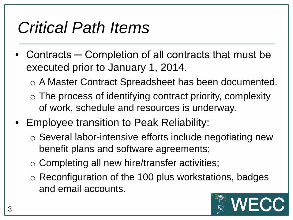
3
• Contracts ─ Completion of all contracts that must be executed prior to January 1, 2014. o A Master Contract Spreadsheet has been documented.
o The process of identifying contract priority, complexity of work, schedule and resources is underway.
• Employee transition to Peak Reliability: o Several labor-intensive efforts include negotiating new
benefit plans and software agreements;
o Completing all new hire/transfer activities;
o Reconfiguration of the 100 plus workstations, badges and email accounts.
Critical Path Items
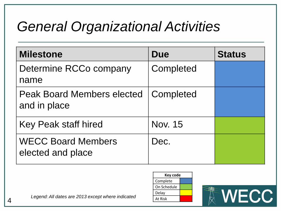
4
General Organizational Activities
Legend: All dates are 2013 except where indicated
Milestone Due Status Determine RCCo company name
Completed
Peak Board Members elected and in place
Completed
Key Peak staff hired Nov. 15
WECC Board Members elected and place
Dec.
Key code Complete On Schedule Delay At Risk

5
Brian Silverstein • Interim Board Committee Chair • Brian Silverstein, resident of Lopez Island, WA, is the Chair of the Interim
Board Committee. Mr. Silverstein retired from Bonneville Power Administration in 2011after a 33-year career. He was most recently Senior Vice President for Transmission Services. Mr. Silverstein has also served on the NERC Reliability Issues Steering Committee.
• Mr. Silverstein earned his master’s degree in electric power from Rensselaer Polytechnic Institute, and his Bachelor's degree in electrical engineering from The Cooper Union. He is a registered professional engineer in Oregon.
Peak Reliability Board of Directors
6
T. GRAHAM EDWARDS • Chief Executive Officer, ElectriCities of North Carolina, WECC
Finance and Audit Committee Chair • Resident of Isle of Palms, South Carolina, has more than 33 years experience
in the electric utility industry, including board of directors’ leadership, serving as president and CEO of three different utilities, and working in a variety of planning and operations roles.
• Since 2009, Mr. Edwards has served as the CEO for ElectriCities of North Carolina, Inc., a public power utility in North Carolina. From 2001–2005, Mr. Edwards sat on the Board of the Midwest Independent System Operator, Inc., serving as its chair in 2005. He remained as President and CEO of the Midwest ISO until 2009.
• Mr. Edwards earned a Bachelor of Science in Business Administration from Francis Marion University, Florence, South Carolina; and a Master of Business Administration from The Citadel, Charleston, South Carolina.
Peak Reliability Board of Directors
7
John Meyer • WECC Standards Committee Chair, WECC Compliance
Committee Member • John Meyer, of Manvel, Texas, joined WECC’s Board as a nonaffiliated director in
2011. He has spent more than 35 years working in engineering, management, and consulting roles in the electric utility industry. Since 2007, Mr. Meyer has been an independent consultant and has served as the chair of the Southwest Power Pool Regional Entity Board of Trustees. He has direct experience with WECC, serving as a member of its Reliability Policy Issues Committee as a representative of Class 7 members.
• Mr. Meyer has worked for Houston Lighting and Power, Reliant Energy, and Reliant Resources. During his career, Mr. Meyer demonstrated expertise in areas such as electric utility operations, regulatory and market rules, transmission line design and planning, and reliability
• Mr. Meyer holds a Bachelor of Science in Electrical Engineering from Lamar University, Beaumont, Texas; and a Master of Science in Electrical Engineering from the University of Houston, Texas.
Peak Reliability Board of Directors

8
Newly Elected Members of the Board as of October 4, 2013
• Robert L. Barnett
• Linda A. Capauno
• Milton B. Lee
• John H. Stout
Link to Credentials here
Peak Reliability Board of Directors
Peak Reliability

10
Legal
Legend: All dates are 2013 except where indicated
Milestone Due Status
Peak officially incorporated Oct. 21
Interchange Authority assignment complete
Nov. 27
Critical contract assignments executed
Dec. 19
WECC assignment of WISP contracts to Peak
Jan. 3, 2014
Key code Complete On Schedule Delay At Risk

11
Employee Transition
Legend: All dates are 2013 except where indicated
Milestone Date Due Status Peak HR system operational Oct. 22
Benefit plans in place Nov. 15
Peak policies and procedures revised and posted
Dec. 31
Employees transferred to Peak Jan. 1, 2014
Key code Complete On Schedule Delay At Risk

12
Finance
Legend: All dates are 2013 except where indicated
Milestone Due Status
Peak payroll system set-up Oct. 15
Peak financial systems in place
Dec. 31
Peak budgeting system in place
Jan. 15, 2014
Peak takes over fixed asset system
Feb. 2, 2014
Key code Completed On Schedule Delay At Risk

13
Information Technology
Legend: All dates are 2013 except where indicated
Milestone Due Status
Confirm Microsoft license transfers to Peak
Completed
Complete Peak server installations
Oct. 10
Peak internet / intranet site ready for rollout
Dec. 16
Complete network configuration/separation
Dec. 31
Key code Completed On Schedule Delay At Risk

Craig L. Williams
UFAS Liaison
Market Interface Manager
801-455-9812
Questions?
Craig L. Williams UFAS Liaison
Market Interface Manager
Enhanced Curtailment Calculator (ECC) Review
October 16, 2013
NWPP Schedulers Meeting
2
• Great Schedulers like yourselves work hard all day long to make sure that every MW has a correct path from source to sink, and it’s all wrong.
What is the root of the USF issue?
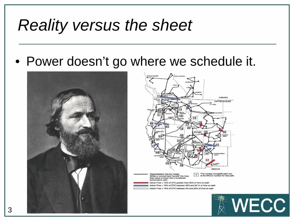
3
• Power doesn’t go where we schedule it.
Reality versus the sheet

4
• The idea of scheduled and unscheduled flow on a contract path is a very Western idea. In most places, no distinction is made between scheduled and unscheduled flow,
– there is just flow. And it follows Kirchhoff's Law.
WECC calls this Unscheduled Flow

5
• Coordinated Operation of Phase Shifters
First WECC uses COPS

6
• WECC next utilizes a congestion management plan that has at its core a software program called webSAS that calculates the magnitude of unscheduled flows and assigns relief obligations to BAs accordingly.
Next Step: webSAS

7
• However, it has also long been known that the webSAS calculations are not complete and therefore it does not provide correct estimations of the magnitude of unscheduled flows, and does not assign relief obligations accurately.
Review of Current Status

8
• The Enhanced Curtailment Calculator (ECC) is a project that would create a “next generation” software program that would correct deficiencies in the webSAS program and add additional capabilities to provide broader tools for congestion management in the Western Interconnection.
Review of Current Status
9
• As part of the cost justification for the Enhanced Curtailment Calculator (ECC), the WECC RC in conjunction with the ECC Advisory Committee identified four (4) major deficiencies currently in the webSAS program and methodologies for the RC to estimate the costs associated with these issues.
Review of Current Status

10
Costs due to webSAS deficiencies
webSAS Calculation Deficiency
Explanation Cost Per Year
Lack of Real-Time Transmission Topology
webSAS uses Transmission Distribution Factors (TDFs) that are calculated twice a year assuming that all lines
are in service. The error associated with this
assumption varies day-to-day but distorts the calculated flows and
relief obligations.
$535,619

11
Costs due to webSAS deficiencies
webSAS Calculation Deficiency
Explanation Cost Per Year
Does not account for non-tagged uses of the Transmission System.
Approximately 40% of the energy flowing on the transmission system in
the Western Interconnection is not tagged and webSAS does not account for
these uses of the system.
$481,652

12
Costs due to webSAS deficiencies
webSAS Calculation Deficiency
Explanation Cost Per Year
Lack of Real-Time Generation Outage
Topology
webSAS does not account for generation
outages in real-time or in its base calculations. The difference between the base case calculations
and the actual generation profiles in the
interconnection result in additional error.
$101,727

13
Costs due to webSAS deficiencies
webSAS Calculation Deficiency
Explanation Cost Per Year
Lack of POR/POD Granularity for e-Tag
Evaluation
webSAS utilizes a series of large zones for
estimating the transmission distribution of flows on the system. The ECC would correct
and enhance this calculation to bring it to
the POR/POD level consistent with the e-tag.
$111,900
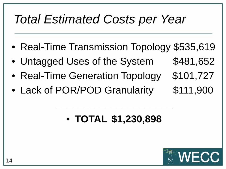
14
• Real-Time Transmission Topology $535,619
• Untagged Uses of the System $481,652
• Real-Time Generation Topology $101,727
• Lack of POR/POD Granularity $111,900
_____________________ • TOTAL $1,230,898
Total Estimated Costs per Year

15
• Book-outs $???
• Liquidated damages $???
• Finding new ATF people $???
• Lost productivity $???
_____________________ • TOTAL $???
Other costs?

16
ECC Timetable
• Phase 1 – RC implements in late 2014 – Real-time grid topology
– POR/POD granularity
– Comparable treatment of tagged and non-tagged uses
– Only Qualified Paths
• Phase 2 – RC implements in late 2015 – Incorporate all monitored transmission elements
– In-hour and dynamic schedules
– Outage Transfer Distribution Factor added

17
What will End Users notice?
• Phase 1 – RC implements in late 2014 – Probably nothing much
– Same interface, better calculations
• Phase 2 – RC implements in late 2015 – More curtailment events possibly for all elements
– Tags and generation subject to curtailment
– A more proactive implementation rather than reactive
• Phase 3 – A new WECC Plan? Markets?

Craig L. Williams
UFAS Liaison
Market Interface Manager
801-455-9812
Questions?

Energy Imbalance Market Implementationgy p
John Appersonpp
October 16, 2013

TopicsTopics
• Energy Imbalance Market (“EIM”) basics
• PacifiCorp stakeholder process, efforts and timeline
• Market design highlights and implementation processesg g g p p
2

EIM basics: what EIM ish k f ff d• The EIM is a market for efficient automated dispatches administered by the Market OperatorR l ti t bil t l t ti f l d i EIM• Relative to bilateral transactions for load service, EIM is anticipated to comprise a very small amount of total transaction volume limited to managing atotal transaction volume, limited to managing a portion of real time imbalances
• Can result in optimization of PacifiCorp’s BAAs or co‐Can result in optimization of PacifiCorp s BAAs or cooptimization with CAISO BAA
3

EIM basics: important “nots”EIM basics: important nots
• An EIM is not a Regional Transmission Organization (RTO). All participating balancing authorities maintain control of their assets and associatedbalancing authorities maintain control of their assets and associated reliability compliance obligations.
– The EIM will not affect PacifiCorp's contingency reserve obligations or reserve p g y gsharing agreements.
• The EIM does not require that parties consolidate balancing authority areas.
• EIM participants are not required to bid‐ they voluntarily make available generation resources that will be optimized to balance load and generation every five minutes across the entire EIM footprint.
4

PacifiCorp stakeholder processPacifiCorp stakeholder process• PacifiCorp stakeholder process designed to mirror ISO process, but account for
timing and procedures specific to PacifiCorp stakeholders• PacifiCorp stakeholder process concludes with the filing of tariff revisions for EIMPacifiCorp stakeholder process concludes with the filing of tariff revisions for EIM
implementation with FERC no later than March 31, 2014• PacifiCorp EIM stakeholder meetings held April 16, May 28, and July 30, 2013• PacifiCorp has published a stakeholder plan with key dates• PacifiCorp also published its EIM Entity Proposal September 13, 2013 and a
revision October 18, 2013• PacifiCorp EIM stakeholder meeting November 6, 2013, in Salt Lake City
All EIM materials and announcements for PacifiCorp’s process are updated and can be found at: http://www.oasis.oati.com/ppw/index.html
5

EIM stakeholder process is working in parallel with PacifiCorp implementationwith PacifiCorp implementation
2013 2014MOU
MOU and Implementation
AgreementFERCreview Implementation work
February 12, 2013
Market simulationJuly ‐ Sept. 2014
FERC
Go live Oct. 1, 2014
T iff l
Process
MergerISO Board authorization November 7‐8, 2013
Agreement filed April 30, 2103
ISO Board authorization March 20, 2013
FERC acceptance June 28, 2013
ISO t k h ldreview
Tariff language
FERC AcceptanceTarget June 1, 2014
ISO stakeholder processes
Filed with FERC no later than February 28, 2014
FERCreview
Tariff languagePacifiCorp stakeholder process
Page 6
Filed with FERC no later than March 31, 2014
FERC AcceptanceTarget July 1, 2014

PacifiCorp’s EIM EIM Participating
Non‐Participating Resources
Participating Resource
External
EIM Entity: PACW
EIM Entity: PACE
Resources
EIM Entity Scheduling Coordinator
PACW
Market Operator (CAISO) EIM (CAISO) Participating
Resource
Page 7
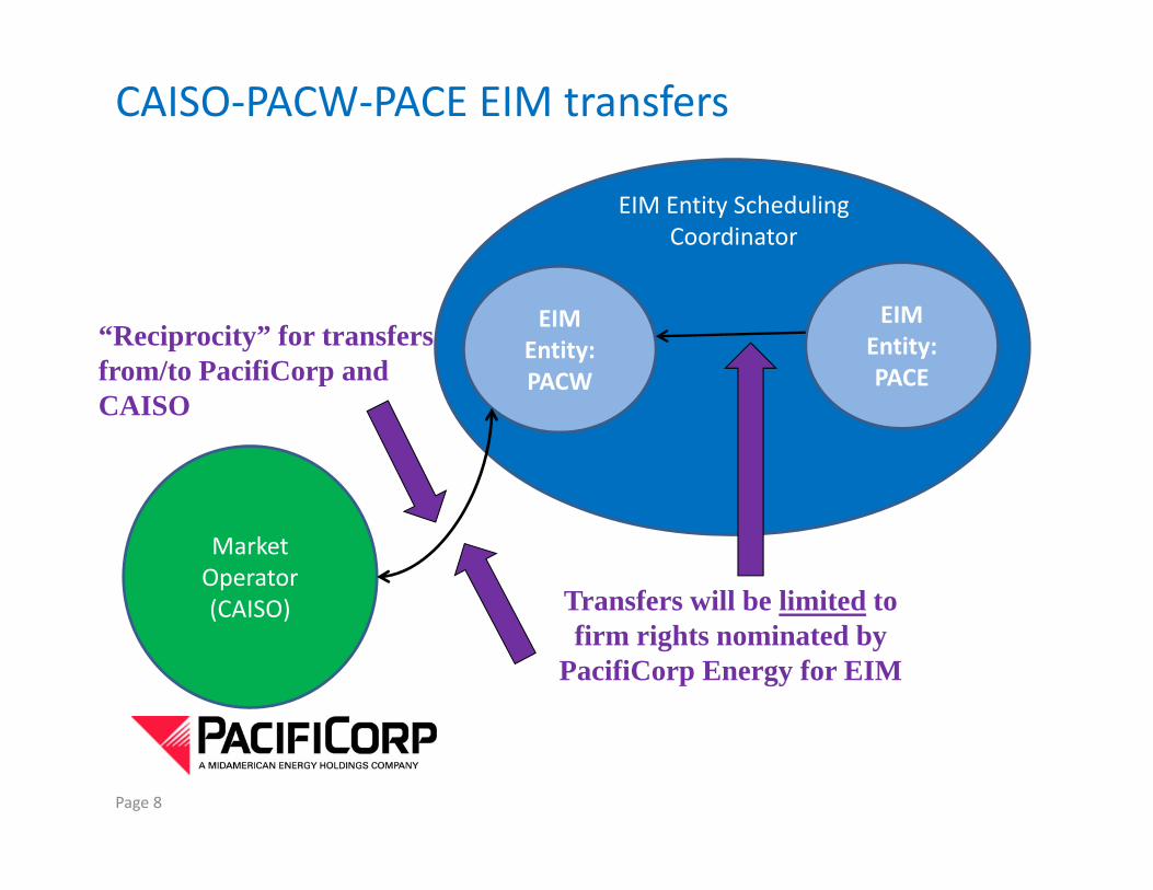
CAISO‐PACW‐PACE EIM transfers
EIM Entity Scheduling Coordinator
EIM Entity: PACW
EIM Entity: PACE
“Reciprocity” for transfers from/to PacifiCorp and PACWCAISO
Market Operator (CAISO) Transfers will be limited to (CAISO)
firm rights nominated by PacifiCorp Energy for EIM
Page 8

EIM Transfers within PacifiCorp
EIM Entity Scheduling Coordinator
EIM Entity: PACW
EIM Entity: PACEPACW
Market Operator (CAISO) EIM flows within PacifiCorp’s (CAISO) p
Balancing Authority Areas based on actual flows or
schedule limits
Page 9

EIM Information ExchangeEIM Entities
(PACW and PACE)(PACW and PACE)9
7Market
Operator (CAISO)
EIM Entity Scheduling Coordinator
3
4
6
108
2
(CAISO)
1 – Base schedule forecasts for all resources and interchange to PAC EIM SIBR Portal (Market Operator produces load forecast)2 – MW bid range and economic bids
InterchangePac EIM
Portal
1
110
EIM Participating
Resource Scheduling 5
2
2 MW bid range and economic bids3 – MW bid range4 – Resource plan, including balanced base schedule information5 – Planned resource outages and after-the-fact forced outages (including estimated return time); revenue meter data (also applicable to Loads)6 – Approved outages (all resources &
Loads
Non-Participating
15
1
10
Scheduling Coordinator
EPR
EPR
5
pp g (transmission, real time and scheduled); revenue meter data7 – Market Operator advisory schedules8 – Dispatch instructions and imbalance settlement for participating resources 9 – Imbalance settlement for loads, interchange and non-participating resources, including BAA
p gResources
p p g gneutrality & uplift charges10 – EIM Entity sub-allocation settlement for loads, interchange and non-participating resources; including BAA neutrality & uplift charges

Questions?Questions?
11
Top Related