


Languages
Pages
Legal

JOURNAL OF THEORETICAL
AND APPLIED MECHANICS
51, 2, pp. 375-385, Warsaw 2013
NUMERICAL TESTING OF FLIGHT STABILITY OF SPIN-STABILIZED
ARTILLERY PROJECTILES
Leszek BaranowskiMilitary University of Technology, Faculty of Mechatronics and Aerospace, Warsaw, Poland
e-mail: [email protected]
The paper presents results of numerical research on the effect of the twist rate, muzzlevelocity, Magnus moment and firing disturbances (cross and range wind) on the stabilityof flight of a Denel 155mm artillery projectile (Assegai M2000 Series) for flat and steeptrajectories.
Key words: spin-stabilized projectile, flight stability, Magnus moment
1. Introduction
Analytical solutions of equations of motion of spin-stabilized artillery projectiles obtained undercertain simplifying assumptions (small total angle of attack αt and fixed factors in linearizeddifferential equations of motion) identify essential conditions for stabilizing projectiles on thewhole trajectory (Dmitrievskij, 1979; Gacek, 1998; Shapiro, 1956)— for the initial (near-straight-line) part of the trajectory, it is required that
σ = 1−b
a2> 0 (1.1)
where a is the precession velocity
a =Ixp02Iy
b =MAαIy=CAmαρV
2Sd
2Iy
— then, for the curvilinear section of the trajectory, it is required that the angle δr containedbetween the vector of velocity of the projectile and the dynamic balance axis is small enoughnot to cause overturning (tumbling) of the projectile near the trajectory apex
δr =2ab
g cos γV=2Ixp0g cos γρV 3SdCAmα
(1.2)
English-language literature (McCoy, 1999; PRODAS v3 User manual; Textbook of Ballisticsand Gunnery, 1987) proposes the following equation for “gyroscopic stability factor” based onlinearized equations of motion of the projectile as a rigid body
Sg =2I2xp
2
πρIyd3V 2CMα(1.3)
The condition for stable projectile flight in the initial section of the trajectory is as follows
Sg > 1 (1.4)
The paper attempts to take a look at the problem of stability of flight of artillery projectile onthe whole flight trajectory based on a non-linear mathematical model of motion of the projectileas a rigid body presented in the earlier Author’s work (2011).
376 L. Baranowski
For this purpose, a computer application was developed for simulating the firing of thetest projectile from Howitzer-gun “Krab” using the aforementioned mathematical model. Denel155mm artillery projectile (Assegai M2000 Series) was used as the test projectile. The computerapplication was used to carry out all-inclusive tests of flight stability of the projectile fired withdifferent muzzle velocities from a 52 caliber barrel to determine the twist rate and quadrantelevation range optimal from the point of view of projectile flight stability. The paper presentsselected results of analysis of firing with extreme charges (minimum velocity VK0 = 319m/s forthe 1st charge and the maximum velocity VK0 = 935m/s for the 6th charge) designed to revealthe following:
• the effect of the twist rate in the end of the barrel expressed in calibers η on the stabilityof flight of the projectile fired at a small and at the maximum quadrant elevation QE;
• the effect of muzzle velocity on dynamic properties of the projectile fired at a small QE(flat trajectory) and the maximum QE (steep trajectory);
• the effect of firing disturbances on the behavior of the projectile on the trajectory.
2. Characteristics of the physical model of the test projectile
The development of the flight simulation computer program of artillery projectiles requires de-termination of the so-called physical model (Dziopa et al., 2010; Koruba et al., 2010; Kowaleczkoand Żyluk, 2009; Ładyżyńska-Kozdraś, 2012), which includes the following characteristics:
a) Structure characteristics:
– geometries– mass and inertia– elasticity
b) Aerodynamic characteristics.
c) Surrounding environment:
– density, viscosity, temperature, pressure, velocity and wind direction depending onweather, flight altitude, etc. The simulation adopted the International Standard At-mosphere (ISO 2533, 1975) as the reference.
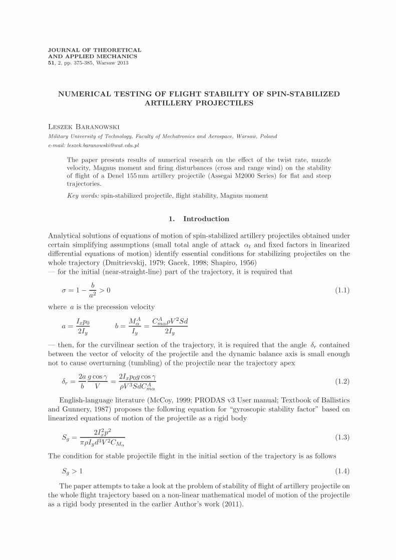
Because of compact design and high rigidity of artillery projectiles, the frequency of propervibration of elastic components of the deliberated test projectile is many times higher than thefrequency of its oscillation around the center of mass, which enables treating the test projectileas a non-deformable solid body with 6 degrees of freedom.
Fig. 1. Overview: test projectile solid model
In line with the prevailing trend, the theoretical calculation of the mass and inertia characte-ristics of the test projectile used the SolidWorks software package from SolidWorks Corporation(one of popular CAD/CAM suites). The computation of the characteristics assumes that theprojectile is an axial-symmetric solid with symmetric mass and inertia. See Fig. 1 for an overview
Numerical testing of flight stability of spin-stabilized artillery projectiles 377
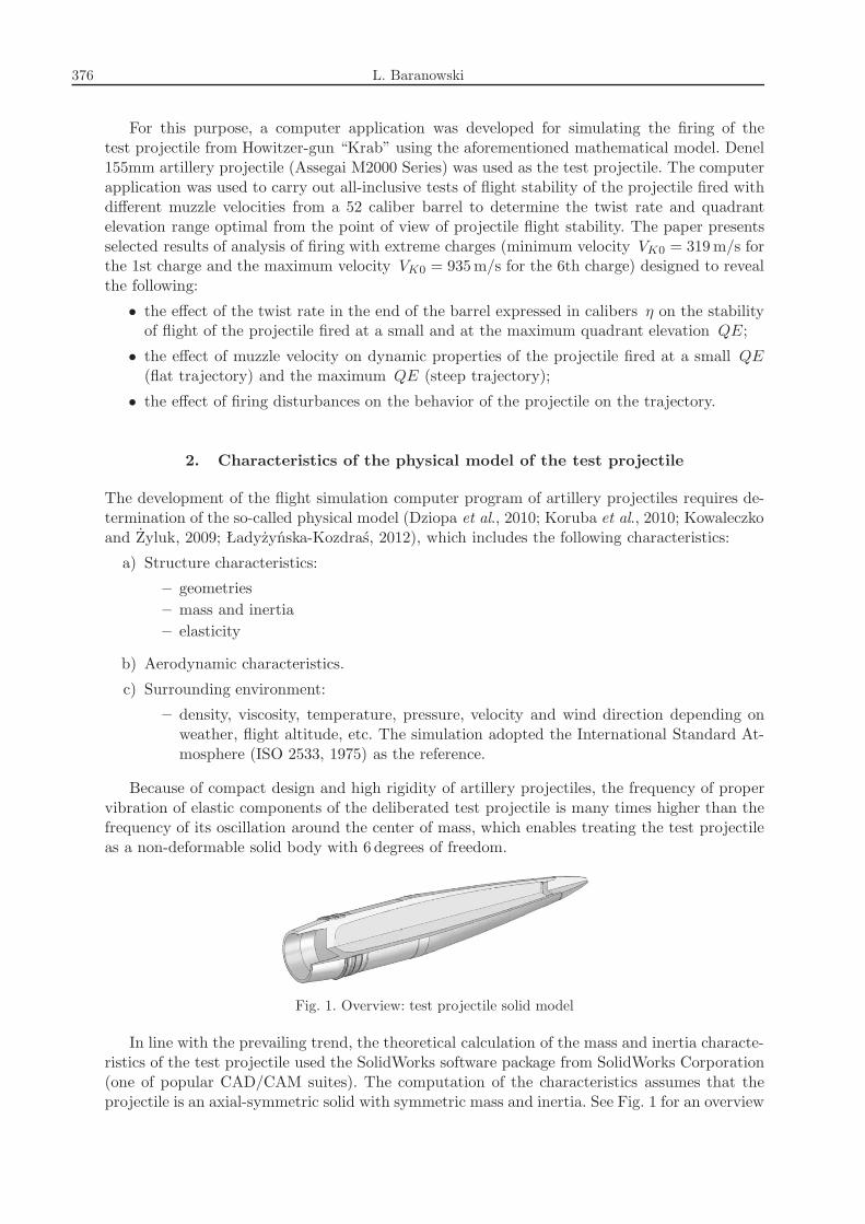
Fig. 2. Main dimensions of the test projectile
of the test projectile (solid model) and Fig. 2 for the main dimensions used for the computationof geometric and aerodynamic characteristics.The mass and inertia characteristics of the test projectile computed using the SolidWorks
software are as follows:
— mass: m = 43.7 kg
— coordinate of position of the center of projectile mass relative to the nose (Fig. 2):xCG = 0.563m
— moments of inertia of the projectile Ix, Iy, Iz in the body-fixed system 0xyz:Ix = 0.1444 kgm2, Iy = 1.7323 kgm2, Iz = 1.7323 kgm2.
Aerodynamic characteristics of the test projectile were determined using an off-shelf softwareapplication: Arrow Tech PRODAS 3.5.3 dedicated to computer-aided designing weaponry. SeeTables 1 and 2 for the results of computation of aerodynamic characteristics as a function of theMach number M for: p∗ = pd/(2V ), q∗ = qd/(2V ), r∗ = rd/(2V ) and S = πd2/4.
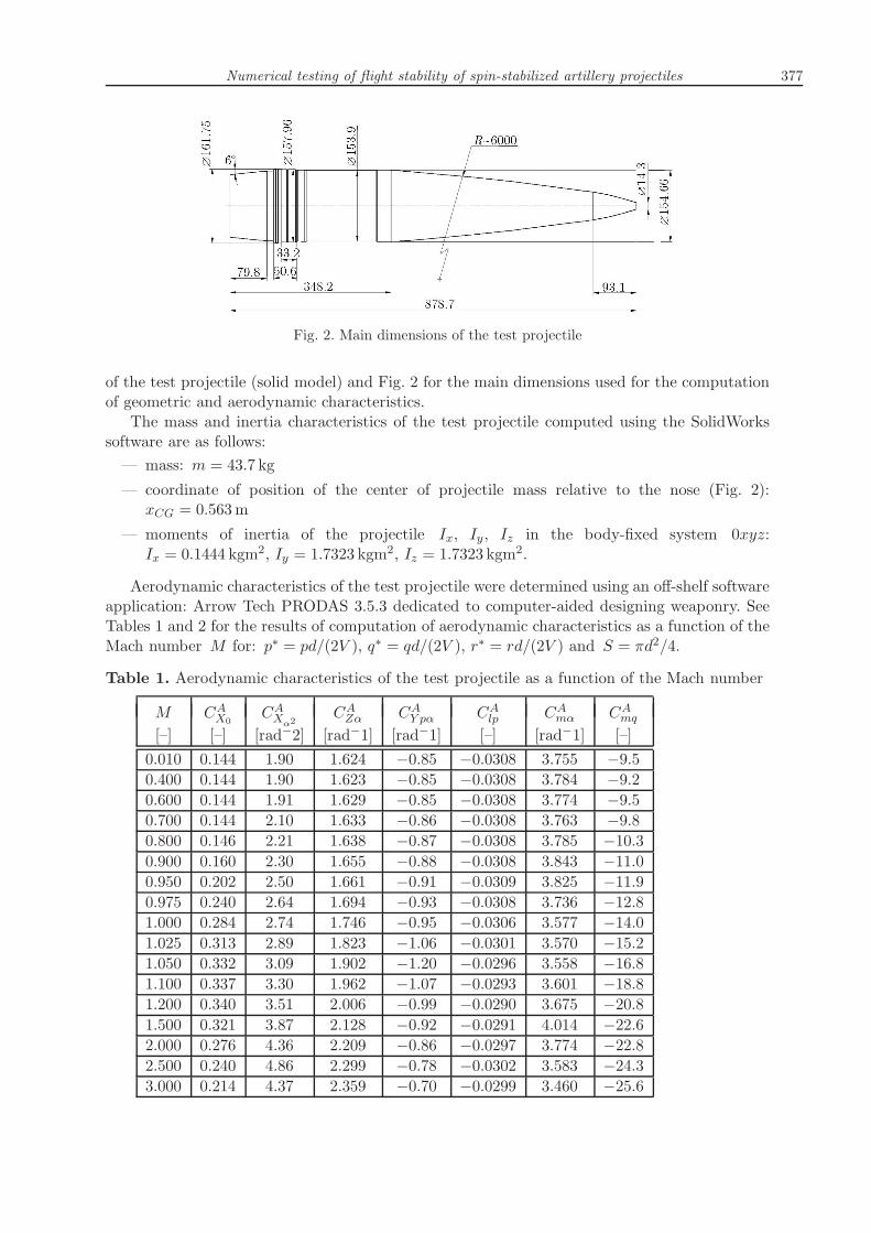
Table 1. Aerodynamic characteristics of the test projectile as a function of the Mach number
M CAX0 CAXα2
CAZα CAY pα CAlp CAmα CAmq[–] [–] [rad−2] [rad−1] [rad−1] [–] [rad−1] [–]
0.010 0.144 1.90 1.624 −0.85 −0.0308 3.755 −9.50.400 0.144 1.90 1.623 −0.85 −0.0308 3.784 −9.20.600 0.144 1.91 1.629 −0.85 −0.0308 3.774 −9.50.700 0.144 2.10 1.633 −0.86 −0.0308 3.763 −9.80.800 0.146 2.21 1.638 −0.87 −0.0308 3.785 −10.30.900 0.160 2.30 1.655 −0.88 −0.0308 3.843 −11.00.950 0.202 2.50 1.661 −0.91 −0.0309 3.825 −11.90.975 0.240 2.64 1.694 −0.93 −0.0308 3.736 −12.81.000 0.284 2.74 1.746 −0.95 −0.0306 3.577 −14.01.025 0.313 2.89 1.823 −1.06 −0.0301 3.570 −15.21.050 0.332 3.09 1.902 −1.20 −0.0296 3.558 −16.81.100 0.337 3.30 1.962 −1.07 −0.0293 3.601 −18.81.200 0.340 3.51 2.006 −0.99 −0.0290 3.675 −20.81.500 0.321 3.87 2.128 −0.92 −0.0291 4.014 −22.62.000 0.276 4.36 2.209 −0.86 −0.0297 3.774 −22.82.500 0.240 4.86 2.299 −0.78 −0.0302 3.583 −24.33.000 0.214 4.37 2.359 −0.70 −0.0299 3.460 −25.6
378 L. Baranowski
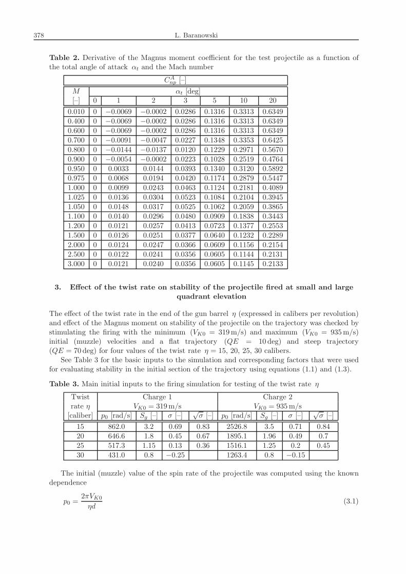
Table 2. Derivative of the Magnus moment coefficient for the test projectile as a function ofthe total angle of attack αt and the Mach number
CAnp [–]
M αt [deg][–] 0 1 2 3 5 10 20
0.010 0 −0.0069 −0.0002 0.0286 0.1316 0.3313 0.63490.400 0 −0.0069 −0.0002 0.0286 0.1316 0.3313 0.63490.600 0 −0.0069 −0.0002 0.0286 0.1316 0.3313 0.63490.700 0 −0.0091 −0.0047 0.0227 0.1348 0.3353 0.64250.800 0 −0.0144 −0.0137 0.0120 0.1229 0.2971 0.56700.900 0 −0.0054 −0.0002 0.0223 0.1028 0.2519 0.47640.950 0 0.0033 0.0144 0.0393 0.1340 0.3120 0.58920.975 0 0.0068 0.0194 0.0420 0.1174 0.2879 0.54471.000 0 0.0099 0.0243 0.0463 0.1124 0.2181 0.40891.025 0 0.0136 0.0304 0.0523 0.1084 0.2104 0.39451.050 0 0.0148 0.0317 0.0525 0.1062 0.2059 0.38651.100 0 0.0140 0.0296 0.0480 0.0909 0.1838 0.34431.200 0 0.0121 0.0257 0.0413 0.0723 0.1377 0.25531.500 0 0.0126 0.0251 0.0377 0.0640 0.1232 0.22892.000 0 0.0124 0.0247 0.0366 0.0609 0.1156 0.21542.500 0 0.0122 0.0241 0.0356 0.0605 0.1144 0.21313.000 0 0.0121 0.0240 0.0356 0.0605 0.1145 0.2133
3. Effect of the twist rate on stability of the projectile fired at small and large
quadrant elevation
The effect of the twist rate in the end of the gun barrel η (expressed in calibers per revolution)and effect of the Magnus moment on stability of the projectile on the trajectory was checked bystimulating the firing with the minimum (VK0 = 319m/s) and maximum (VK0 = 935m/s)initial (muzzle) velocities and a flat trajectory (QE = 10 deg) and steep trajectory(QE = 70 deg) for four values of the twist rate η = 15, 20, 25, 30 calibers.See Table 3 for the basic inputs to the simulation and corresponding factors that were used
for evaluating stability in the initial section of the trajectory using equations (1.1) and (1.3).
Table 3. Main initial inputs to the firing simulation for testing of the twist rate η
Twist Charge 1 Charge 2rate η VK0 = 319m/s VK0 = 935m/s[caliber] p0 [rad/s] Sg [–] σ [–]
√σ [–] p0 [rad/s] Sg [–] σ [–]
√σ [–]
15 862.0 3.2 0.69 0.83 2526.8 3.5 0.71 0.8420 646.6 1.8 0.45 0.67 1895.1 1.96 0.49 0.725 517.3 1.15 0.13 0.36 1516.1 1.25 0.2 0.4530 431.0 0.8 −0.25 1263.4 0.8 −0.15
The initial (muzzle) value of the spin rate of the projectile was computed using the knowndependence
p0 =2πVK0ηd
(3.1)
Numerical testing of flight stability of spin-stabilized artillery projectiles 379
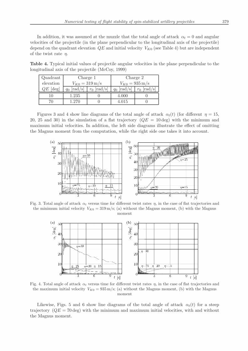
In addition, it was assumed at the muzzle that the total angle of attack αt = 0 and angularvelocities of the projectile (in the plane perpendicular to the longitudinal axis of the projectile)depend on the quadrant elevation QE and initial velocity VK0 (see Table 4) but are independentof the twist rate η.
Table 4. Typical initial values of projectile angular velocities in the plane perpendicular to thelongitudinal axis of the projectile (McCoy, 1999)
Quadrant Charge 1 Charge 2elevation VK0 = 319m/s VK0 = 935m/sQE [deg] q0 [rad/s] r0 [rad/s] q0 [rad/s] r0 [rad/s]
10 1.235 0 4.000 070 1.270 0 4.015 0
Figures 3 and 4 show line diagrams of the total angle of attack αt(t) (for different η = 15,20, 25 and 30) in the simulation of a flat trajectory (QE = 10 deg) with the minimum andmaximum initial velocities. In addition, the left side diagrams illustrate the effect of omittingthe Magnus moment from the computation, while the right side one takes it into account.
Fig. 3. Total angle of attack αt versus time for different twist rates η, in the case of flat trajectories andthe minimum initial velocity VK0 = 319m/s; (a) without the Magnus moment, (b) with the Magnus
moment
Fig. 4. Total angle of attack αt versus time for different twist rates η, in the case of flat trajectories andthe maximum initial velocity VK0 = 935m/s; (a) without the Magnus moment, (b) with the Magnus
moment
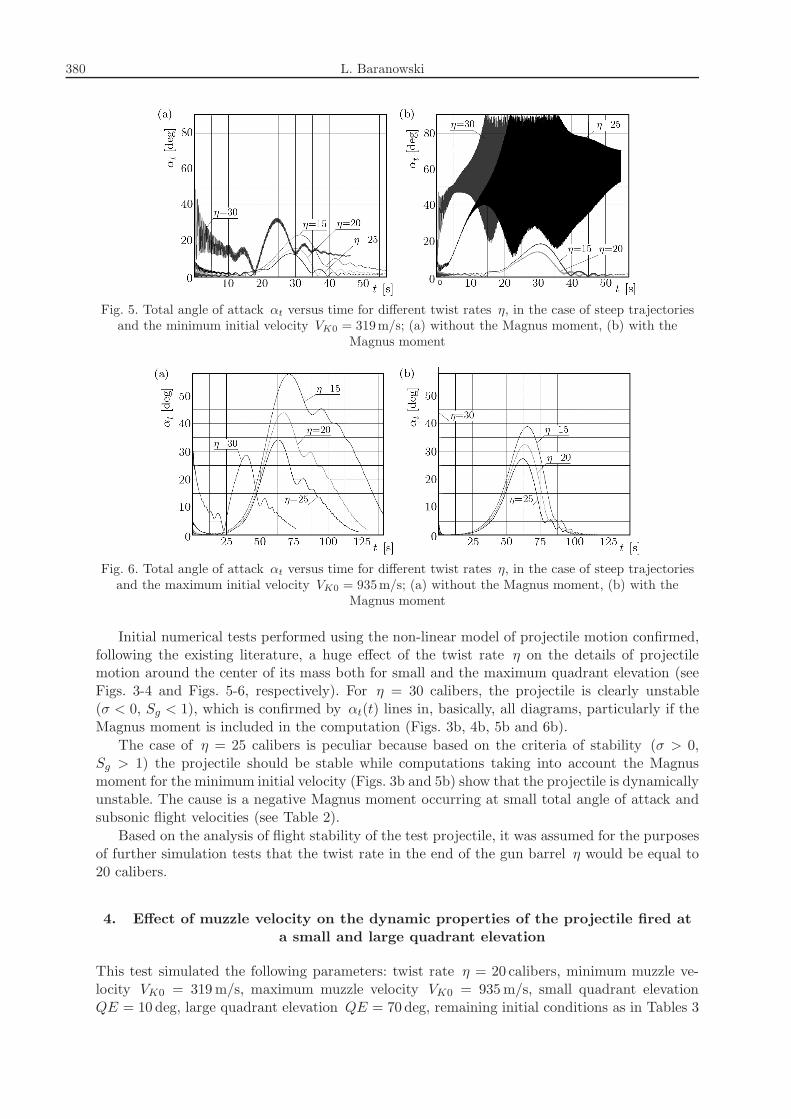
Likewise, Figs. 5 and 6 show line diagrams of the total angle of attack αt(t) for a steeptrajectory (QE = 70 deg) with the minimum and maximum initial velocities, with and withoutthe Magnus moment.
380 L. Baranowski
Fig. 5. Total angle of attack αt versus time for different twist rates η, in the case of steep trajectoriesand the minimum initial velocity VK0 = 319m/s; (a) without the Magnus moment, (b) with the
Magnus moment
Fig. 6. Total angle of attack αt versus time for different twist rates η, in the case of steep trajectoriesand the maximum initial velocity VK0 = 935m/s; (a) without the Magnus moment, (b) with the
Magnus moment
Initial numerical tests performed using the non-linear model of projectile motion confirmed,following the existing literature, a huge effect of the twist rate η on the details of projectilemotion around the center of its mass both for small and the maximum quadrant elevation (seeFigs. 3-4 and Figs. 5-6, respectively). For η = 30 calibers, the projectile is clearly unstable(σ < 0, Sg < 1), which is confirmed by αt(t) lines in, basically, all diagrams, particularly if theMagnus moment is included in the computation (Figs. 3b, 4b, 5b and 6b).The case of η = 25 calibers is peculiar because based on the criteria of stability (σ > 0,
Sg > 1) the projectile should be stable while computations taking into account the Magnusmoment for the minimum initial velocity (Figs. 3b and 5b) show that the projectile is dynamicallyunstable. The cause is a negative Magnus moment occurring at small total angle of attack andsubsonic flight velocities (see Table 2).Based on the analysis of flight stability of the test projectile, it was assumed for the purposes
of further simulation tests that the twist rate in the end of the gun barrel η would be equal to20 calibers.
4. Effect of muzzle velocity on the dynamic properties of the projectile fired at
a small and large quadrant elevation
This test simulated the following parameters: twist rate η = 20 calibers, minimum muzzle ve-locity VK0 = 319m/s, maximum muzzle velocity VK0 = 935m/s, small quadrant elevationQE = 10 deg, large quadrant elevation QE = 70 deg, remaining initial conditions as in Tables 3
Numerical testing of flight stability of spin-stabilized artillery projectiles 381
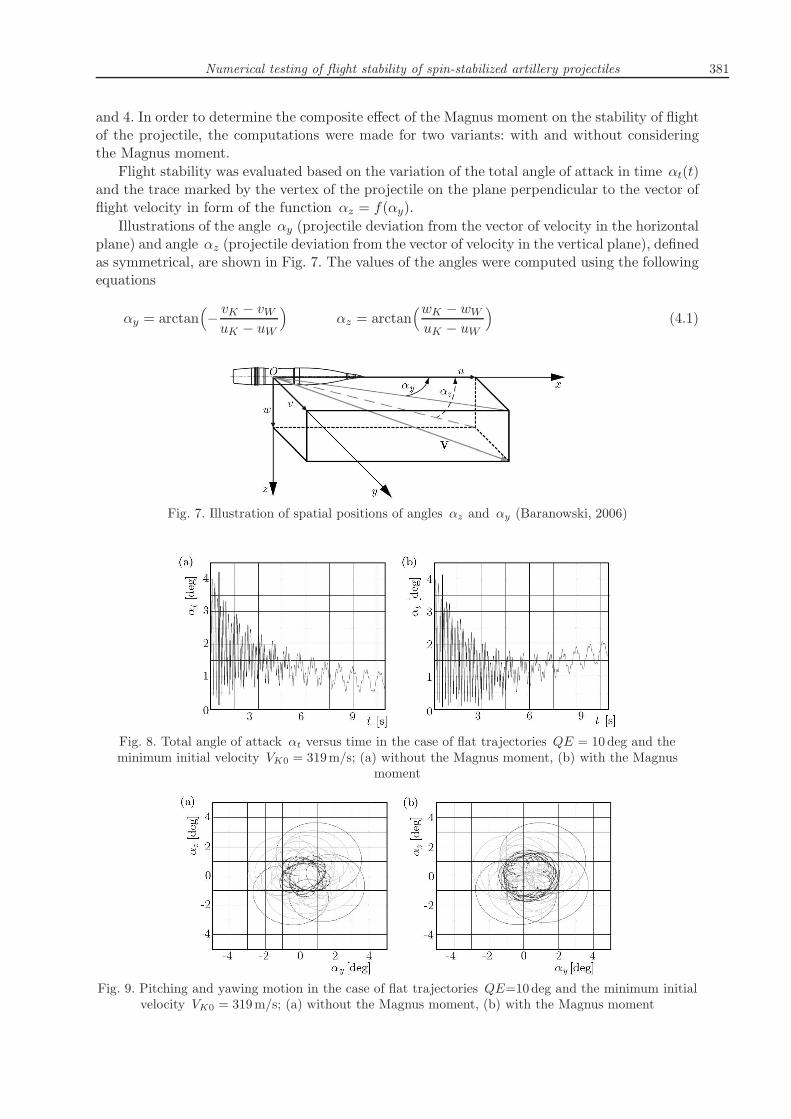
and 4. In order to determine the composite effect of the Magnus moment on the stability of flightof the projectile, the computations were made for two variants: with and without consideringthe Magnus moment.Flight stability was evaluated based on the variation of the total angle of attack in time αt(t)
and the trace marked by the vertex of the projectile on the plane perpendicular to the vector offlight velocity in form of the function αz = f(αy).Illustrations of the angle αy (projectile deviation from the vector of velocity in the horizontal
plane) and angle αz (projectile deviation from the vector of velocity in the vertical plane), definedas symmetrical, are shown in Fig. 7. The values of the angles were computed using the followingequations
αy = arctan(
−vK − vWuK − uW
)
αz = arctan(wK − wWuK − uW
)
(4.1)
Fig. 7. Illustration of spatial positions of angles αz and αy (Baranowski, 2006)
Fig. 8. Total angle of attack αt versus time in the case of flat trajectories QE = 10deg and theminimum initial velocity VK0 = 319m/s; (a) without the Magnus moment, (b) with the Magnus
moment
Fig. 9. Pitching and yawing motion in the case of flat trajectories QE=10deg and the minimum initialvelocity VK0 = 319m/s; (a) without the Magnus moment, (b) with the Magnus moment
382 L. Baranowski
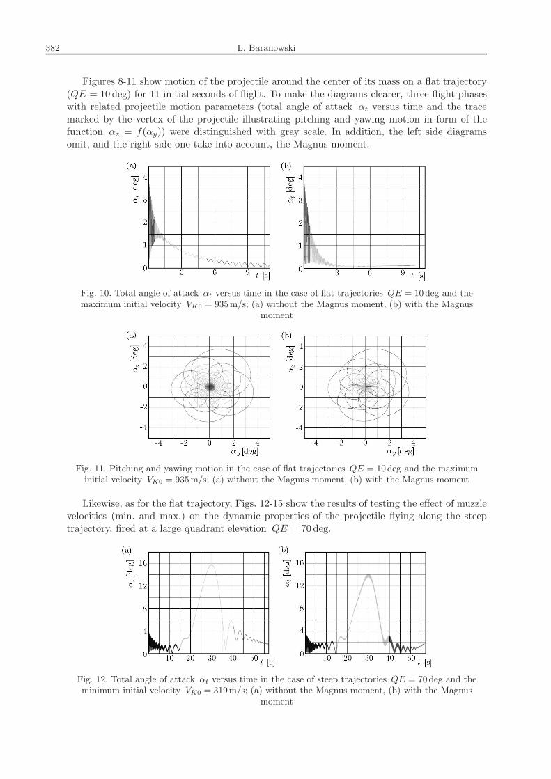
Figures 8-11 show motion of the projectile around the center of its mass on a flat trajectory(QE = 10 deg) for 11 initial seconds of flight. To make the diagrams clearer, three flight phaseswith related projectile motion parameters (total angle of attack αt versus time and the tracemarked by the vertex of the projectile illustrating pitching and yawing motion in form of thefunction αz = f(αy)) were distinguished with gray scale. In addition, the left side diagramsomit, and the right side one take into account, the Magnus moment.
Fig. 10. Total angle of attack αt versus time in the case of flat trajectories QE = 10deg and themaximum initial velocity VK0 = 935m/s; (a) without the Magnus moment, (b) with the Magnus
moment
Fig. 11. Pitching and yawing motion in the case of flat trajectories QE = 10deg and the maximuminitial velocity VK0 = 935m/s; (a) without the Magnus moment, (b) with the Magnus moment
Likewise, as for the flat trajectory, Figs. 12-15 show the results of testing the effect of muzzlevelocities (min. and max.) on the dynamic properties of the projectile flying along the steeptrajectory, fired at a large quadrant elevation QE = 70 deg.
Fig. 12. Total angle of attack αt versus time in the case of steep trajectories QE = 70deg and theminimum initial velocity VK0 = 319m/s; (a) without the Magnus moment, (b) with the Magnus
moment
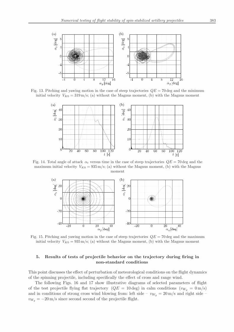
Numerical testing of flight stability of spin-stabilized artillery projectiles 383
Fig. 13. Pitching and yawing motion in the case of steep trajectories QE = 70deg and the minimuminitial velocity VK0 = 319m/s; (a) without the Magnus moment, (b) with the Magnus moment
Fig. 14. Total angle of attack αt versus time in the case of steep trajectories QE = 70deg and themaximum initial velocity VK0 = 935m/s; (a) without the Magnus moment, (b) with the Magnus
moment
Fig. 15. Pitching and yawing motion in the case of steep trajectories QE = 70deg and the maximuminitial velocity VK0 = 935m/s; (a) without the Magnus moment, (b) with the Magnus moment
5. Results of tests of projectile behavior on the trajectory during firing in
non-standard conditions
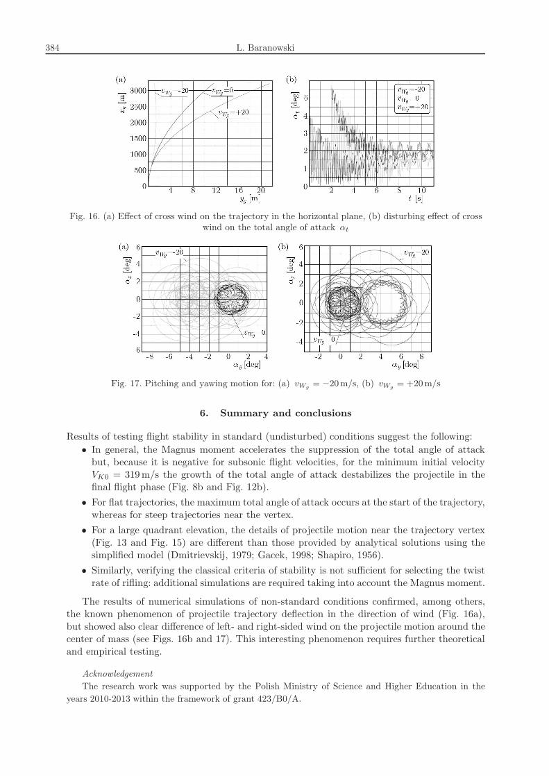
This point discusses the effect of perturbation of meteorological conditions on the flight dynamicsof the spinning projectile, including specifically the effect of cross and range wind.The following Figs. 16 and 17 show illustrative diagrams of selected parameters of flight
of the test projectile flying flat trajectory (QE = 10 deg) in calm conditions (vWg = 0m/s)and in conditions of strong cross wind blowing from: left side – vWg = 20m/s and right side –vWg = −20m/s since second second of the projectile flight.
384 L. Baranowski
Fig. 16. (a) Effect of cross wind on the trajectory in the horizontal plane, (b) disturbing effect of crosswind on the total angle of attack αt
Fig. 17. Pitching and yawing motion for: (a) vWg = −20m/s, (b) vWg = +20m/s
6. Summary and conclusions
Results of testing flight stability in standard (undisturbed) conditions suggest the following:• In general, the Magnus moment accelerates the suppression of the total angle of attackbut, because it is negative for subsonic flight velocities, for the minimum initial velocityVK0 = 319m/s the growth of the total angle of attack destabilizes the projectile in thefinal flight phase (Fig. 8b and Fig. 12b).
• For flat trajectories, the maximum total angle of attack occurs at the start of the trajectory,whereas for steep trajectories near the vertex.
• For a large quadrant elevation, the details of projectile motion near the trajectory vertex(Fig. 13 and Fig. 15) are different than those provided by analytical solutions using thesimplified model (Dmitrievskij, 1979; Gacek, 1998; Shapiro, 1956).
• Similarly, verifying the classical criteria of stability is not sufficient for selecting the twistrate of rifling: additional simulations are required taking into account the Magnus moment.
The results of numerical simulations of non-standard conditions confirmed, among others,the known phenomenon of projectile trajectory deflection in the direction of wind (Fig. 16a),but showed also clear difference of left- and right-sided wind on the projectile motion around thecenter of mass (see Figs. 16b and 17). This interesting phenomenon requires further theoreticaland empirical testing.
Acknowledgement
The research work was supported by the Polish Ministry of Science and Higher Education in theyears 2010-2013 within the framework of grant 423/B0/A.
Numerical testing of flight stability of spin-stabilized artillery projectiles 385
References
1. Baranowski L., 2006, A mathematical model of flight dynamics of field artillery guided projectiles,6th International Conference on Weaponry “Scientific Aspects of Weaponry”, Waplewo, 44-53 [inPolish]
2. Baranowski L., 2011, Modeling, Identification and Numerical Study of the Flight Dynamics ofBallistic Objects for the Need of Field Artillery Fire Control Systems, Military University of Tech-nology, Warsaw, p. 258 [in Polish]
3. Dmitrievskij A.A., 1979, External Ballistics, Mashinostroenie, Moscow [in Russian]
4. Dziopa Z., Krzysztofik I., Koruba Z., 2010, An analysis of the dynamics of a launcher-missileon a moveable base, Bulletin of the Polish Academy of Sciences – Technical Sciences, 58, 4, 645-650
5. Gacek J., 1998, Exterior Ballistics. Part II. Analysis of Dynamic Properties of Objects in Flight,Military University of Technology, Warsaw, p. 316 [in Polish]
6. Koruba Z., Dziopa Z., Krzysztofik I., 2010, Dynamics and control of a gyroscope-stabilizedplatform in a self-propelled anti-aircraft system, Journal of Theoretical and Applied Mechanics, 48,1, 5-26
7. Kowaleczko G., Żyluk A., 2009, Influence of atmospheric turbulence on bomb release, Journalof Theoretical and Applied Mechanics, 47, 1, 69-90
8. Ładyżyńska-Kozdraś E., 2012, Modeling and numerical simulation of unmanned aircraft vehiclerestricted by non-holonomic constraints, Journal of Theoretical and Applied Mechanics, 50, 1,251-268
9. McCoy R.L., 1999, Modern Exterior Ballistics. The Launch and Flight Dynamics of SymmetricProjectiles, Schiffer Publishing
10. Shapiro J., 1956, Exterior Ballistics, MON, Warsaw [Polish translation]
11. PRODAS v3 User manual
12. Textbook of Ballistics and Gunnery, 1987, Her Majesty’s Stationary Office, London
13. The Modified Point Mass and Five Degrees of Freedom Trajectory Models, 2009, STANAG 4355Edition 3
14. The ISO Standard Atmosphere, 1975, ISO 2533
Badania numeryczne stabilności lotu klasycznego pocisku artyleryjskiego
stabilizowanego obrotowo
Streszczenie
W pracy przedstawiono wyniki badań numerycznych wpływu długości skoku gwintu lufy, prędkościpoczątkowej pocisku, momentu Magnusa oraz zakłóceń warunków strzelania (wiatru podłużnego i boczne-go) na stabilność lotu 155mm pocisku artyleryjskiego firmy Denel (Assegai M2000 Series) dla przypadkupłaskiego i stromego toru lotu.
Manuscript received May 8, 2012; accepted for print July 2, 2012
Top Related