


Languages
Pages
Legal

Numerical Study of Flow in a Centrifugal Blower
1ISHAN VARMA, 2RANJITH MANIYERI Department of Mechanical Engineering Symbiosis Institute of Technology (SIT) Symbiosis International University (SIU)
Lavale, Pune, Maharashtra-412115, INDIA Corresponding Author:[email protected]
Abstract: - Analysis of fluid flow in a centrifugal blower is essential to understand the flow pattern which helps to explore its detailed performance for the better design. The objective of the present study is to estimate the performance characteristics and the flow field in the centrifugal blower under variable inlet parameters by numerical analysis. In this paper numerical simulations are carried out on a standard finite volume open source code using Moving Reference Frame (MRF) methodology. Reynolds Averaged Navier-Stokes equations for incompressible flow is solved with standard eddy-viscosity k-epsilon model to study the aerodynamic properties of the blower. The model is created in a standard CAD software and is imported to the mesh generation software for Geometry Clean-Up and for the generation of Unstructured Mesh: Triangle type (surface mesh) and hybrid mesh consisting of Tetra and Prism layers (Volume mesh).Solving and post processing is done thereafter wherein static pressure rise, velocity, volume coefficient and head coefficient of the centrifugal blower are determined under different variable inlet parameters like volume flow rate, rotational speed, inlet velocity and the stream lines are observed which are critical to the design. Key-Words:Centrifugal Blower, Computational Fluid Dynamics, Navier-Stokes Equations, Moving ReferenceFrame, k-epsilon Turbulence Model. 1. Introduction Blowers are one of the types of turbo machines which are used to move air continuously with slight increase in static pressure. As the impellor starts rotating, the working fluid near the impeller is pushed outwards from the impeller due to the action of the centrifugal forces which then circulates into the casing of the blower. As a result, the operating pressure of the working fluid in the blower casing is enhanced. The working fluid is then guided to the exit via outlet ducts. After the working fluid leaves the outlet duct, the pressure inside the middle region of the impeller decreases which creates a suction pressure for the fluid. The centrifugal blower consists of blower housing, impeller, inlet and outlet ducts, drive shaft, drive mechanism, rotating wheel which is composed of variable number of blower blades, or ribs, mounted around a hub. Drive shaft provides turning power to the hub, which passes through the blower housing. Owing to its extensive use in the industry, centrifugal blowers are designed and manufactured in a systematic procedure which results in better efficiency and low cost of energy requirements [1].
Working of the blower system depends on various conditions, some of them are: rate of fluid flow, fluid temperature, fluid properties, inlet pressure, and outlet pressure. Centrifugal blowers are analysed by its performance curves which comprises of the plots of developed pressure, head coefficient, volume coefficient and power required over a range of air flow. These performance curves can be identified, analysed and evaluated by theoretical calculations, computations or by series of experiments. However, performing the experimental analysis is a challenging task augmented with time and manufacturing costs. Therefore, to evaluate the predicted performance of the blower, various computational methods are employed which not only offer reliable solutions but also save time and expenditure by excluding the need to manufacture the prototypes. Blower performance is analysed in accordance to the rotational frequency of impeller while the static pressure is set as the inlet condition. The results obtained fromnumerical simulations are used for internal flow pattern visualisation and detailed flow analysis of the blower. In the recent years, drafting of the manufacturing drawings for the automation and efficient control of the centrifugal fan has led to an increase in
WSEAS TRANSACTIONS on FLUID MECHANICS Ishan Varma, Ranjith Maniyeri
E-ISSN: 2224-347X 1 Volume 13, 2018
reliability owing to which failures are rare; however, it limits the design’s efficiency. Various methods were developed in 1950’s for interpolating the fan’s performance which helped in predicting the characteristics of aerodynamic performance, but also the sub-optimal performance [2, 3]. From 1980 onwards, research in the field of centrifugal blowers has led to the development of new computational fluid dynamics (CFD) techniques for simulating flow through turbo machines. Lin and Tsai [4] studied, analysed and evaluated the performance characteristics of backward-inclined centrifugal fan under different operating conditions through a combined experimental and numerical approach. The numerical results thus obtained are utilized to perform detailed flow visualization, torque calculation, efficiency estimation, and noise analysis. Pan et al. [5] evaluated the performance of a centrifugal fan volute by solving the standard k–epsilon turbulence model and compared it with the experimental results.Hassan et al. [6] found large air flow deviation in test and CFD results at high pressure and low air flow rate using steady realizable k-epsilon model and then concluded that CFD analysis is more accurate for smaller mass flow rate.Liu et al. [7] numerically studied the three-dimensional turbulence flow in a shrouded centrifugal impeller by using two different turbulent models. At the same time, a comparison was made between the computational results and the previous experimental measurements. It was concluded that under the design conditions, the main flow velocity and the secondary flow in the impeller were well predicted by the two models.Jang et al. [8] studied numerically and experimentally the various performance characteristics of a turbo blower installed in the refuse collecting system. In refuse collecting system, relationship between system efficiency and system resistance curve was established. Also, it was found that a large recirculation flow is formed in the blade passage located near the cut-off region and the input energy of the turbo blower can be reduced by controlling the rotational frequency of the impeller while the efficiency of the blower kept constant. Vibhakar et al. [9] analysed a backward curved radial tipped blade centrifugal fan using CFD to understand the volute-impeller interaction at design and off-design conditions under specific parameters like varying mass flow rates, number of blades and rotational speeds of the impeller. Steady state, realizable k-epsilon model with Moving Reference Frame (MRF) approach was used to evaluate the flow behaviour and the performance curves were plotted. Numerical analysis was used to visualise the
flow streamlines which clearly indicates the rotating effect of blades on flow, within and outside of impeller zone. Zhang et al. [10] computed the three-dimensional viscous flow in a backwards swept centrifugal fan impeller blade passage at its design point by solving the Reynolds Averaged Navier-Stokes (RANS) equations using standard eddy viscosity turbulence closure. Karnath and Sharma [11,12] suggested various performance enhancement methods in blade passage of centrifugal fan using CFD simulations. Alessandro et al. [15] studied the flow field in a centrifugal fan designed for process industry applications with the aim of highlighting the critical regions inside the device especially near the blades and provide modifications to increase its life. They carried out numerical computations on the finite volume open-source code OpenFOAM using Multiple Reference Frame methodology. Reynolds Averaged Navier-Stokes equations for incompressible flow were solved with the eddy-viscosity k-epsilon model to explore the aerodynamic behavior of fan near-design operations. Similar to the work done by Alessandro et al. [15] we will simulate our model using Multiple Reference Frame methodology with the help of Reynolds Averaged Navier-Stokes equation supplemented with k-epsilon model. But in this paper, a different hybrid mesh generating technique is used in another finite volume code and finally we aim to validate our results with the latter [15]. We also aim to study the performance characteristics of the blower at design and off design conditions. 2 Modelling and Numerical Procedure A characteristic design parameter of centrifugal blower is the ratio of outer diameter to inlet diameter of the impellor blade channel [13]. In standard design, the ratio is small, within 1.2 to 1.45 and the blade radial length is (0.84 to 0.16) x outer diameter. In the present study, the blower system is designed in the CAD software in conformance to the characteristic design parameters. Design specifications of the centrifugal blower system are summarised in Table 1. The inlet diameter of the blower is 36 cm and the outlet diameter is 43 cm. It consists of 8 backward curved impellor blades with stators between them to guide the flow of fluid between the blades. The inlet and the outlet are extended outwards from the actual geometry to
WSEAS TRANSACTIONS on FLUID MECHANICS Ishan Varma, Ranjith Maniyeri
E-ISSN: 2224-347X 2 Volume 13, 2018
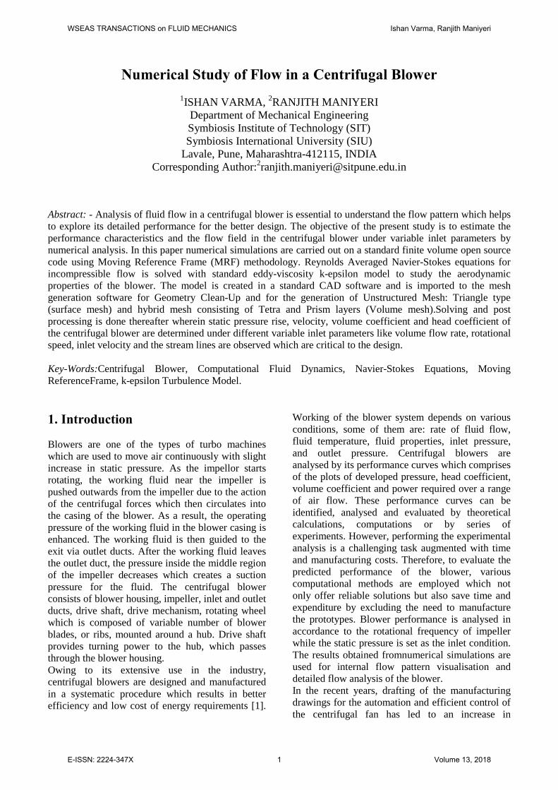
prevent the formation of vortex. The various parts of the blower: spiral casing, impeller, shaft, suction arrangement, supporting structure are generated individually and then assembled to backward curved impeller blades in the CAD software. The fluid enters the centrifugal blower from inlet and turns orthogonally through the impellor blades to the outlet. Figure 1 represents the CAD model of the blower system. Table 1. Design specifications of the blower
Fig. 1. Representation of the blower model. To simulate the complex flow patterns in the centrifugal blower, a commercial CFD code is utilized which solves the incompressible Navier-Stokes equation complimented by the k-Ɛ turbulence model:
……………. (1)
Where is the fluid density, is the fluid velocity,
is the pressure, is the deviatory component of the total stress tensor, which has order two,
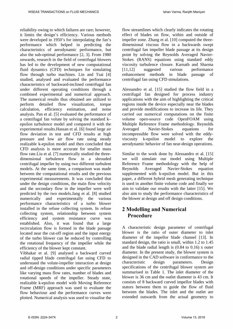
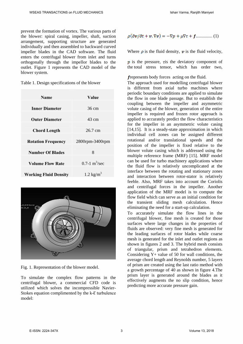
represents body forces acting on the fluid. The approach used for modelling centrifugal blower is different from axial turbo machines where periodic boundary conditions are applied to simulate the flow in one blade passage. But to establish the coupling between the impeller and asymmetric volute casing of the blower, generation of the entire impeller is required and frozen rotor approach is applied to accurately predict the flow characteristics for the impeller in an asymmetric volute casing [14,15]. It is a steady-state approximation in which individual cell zones can be assigned different rotational and/or translational speeds and the position of the impeller is fixed relative to the blower volute casing which is addressed using the multiple reference frame (MRF) [15]. MRF model can be used for turbo machinery applications where the fluid flow is relatively uncomplicated at the interface between the rotating and stationary zones and interaction between rotor-stator is relatively feeble. Also, MRF takes into account the Coriolis and centrifugal forces in the impeller. Another application of the MRF model is to compute the flow field which can serve as an initial condition for the transient sliding mesh calculation. Hence eliminating the need for a start-up calculation. To accurately simulate the flow lines in the centrifugal blower, fine mesh is created for those surfaces where large changes in the properties of fluids are observed: very fine mesh is generated for the leading surfaces of rotor blades while coarse mesh is generated for the inlet and outlet regions as shown in figures 2 and 3. The hybrid mesh consists of triangular, prism and tetrahedron elements. Considering Y+ value of 50 for wall conditions, the average chord length and Reynolds number, 5 layers of prism are created using the last ratio method with a growth percentage of 40 as shown in figure 4.The prism layer is generated around the blades as it effectively augments the no slip condition, hence predicting more accurate pressure gain.
Name
Value
Inner Diameter
36 cm
Outer Diameter
43 cm
Chord Length
26.7 cm
Rotation Frequency
2800rpm-3400rpm
Number Of Blades
8
Volume Flow Rate
0.7-1 m3/sec
Working Fluid Density
1.2 kg/m3
WSEAS TRANSACTIONS on FLUID MECHANICS Ishan Varma, Ranjith Maniyeri
E-ISSN: 2224-347X 3 Volume 13, 2018
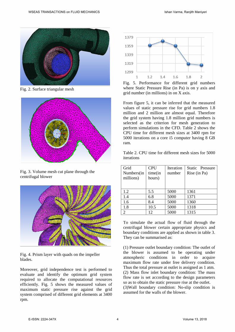
Fig. 2. Surface triangular mesh
Fig. 3. Volume mesh cut plane through the centrifugal blower
Fig. 4. Prism layer with quads on the impeller blades. Moreover, grid independence test is performed to evaluate and identify the optimum grid system required to allocate the computational resources efficiently. Fig. 5 shows the measured values of maximum static pressure rise against the grid system comprised of different grid elements at 3400 rpm.
Fig. 5. Performance for different grid numbers where Static Pressure Rise (in Pa) is on y axis and grid number (in millions) in on X axis. From figure 5, it can be inferred that the measured values of static pressure rise for grid numbers 1.8 million and 2 million are almost equal. Therefore the grid system having 1.8 million grid numbers is selected as the criterion for mesh generation to perform simulations in the CFD. Table 2 shows the CPU time for different mesh sizes at 3400 rpm for 5000 iterations on a core i5 computer having 8 GB ram. Table 2. CPU time for different mesh sizes for 5000 iterations Grid Numbers(in millions)
CPU time(in hours)
Iteration number
Static Pressure Rise (in Pa)
1.2 5.5 5000 1361 1.4 6.8 5000 1371 1.6 8.4 5000 1360 1.8 10.5 5000 1318 2 12 5000 1315 To simulate the actual flow of fluid through the centrifugal blower certain appropriate physics and boundary conditions are applied as shown in table 3. They can be summarised as: (1) Pressure outlet boundary condition: The outlet of the blower is assumed to be operating under atmospheric conditions in order to acquire maximum flow rate under free delivery condition. Thus the total pressure at outlet is assigned as 1 atm. (2) Mass flow inlet boundary condition: The mass flow rate is set according to the design parameters so as to obtain the static pressure rise at the outlet. (3)Wall boundary condition: No-slip condition is assumed for the walls of the blower.
WSEAS TRANSACTIONS on FLUID MECHANICS Ishan Varma, Ranjith Maniyeri
E-ISSN: 2224-347X 4 Volume 13, 2018
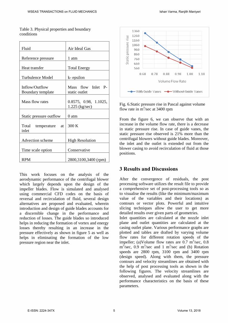
Table 3. Physical properties and boundary conditions
Fluid Air Ideal Gas
Reference pressure 1 atm
Heat transfer Total Energy
Turbulence Model k- epsilon
Inflow/Outflow Boundary template
Mass flow Inlet P-static outlet
Mass flow rates 0.8575, 0.98, 1.1025, 1.225 (kg/sec)
Static pressure outflow 0 atm
Total temperature at inlet
300 K
Advection scheme High Resolution
Time scale option Conservative
RPM 2800,3100,3400 (rpm) This work focuses on the analysis of the aerodynamic performance of the centrifugal blower which largely depends upon the design of the impeller blades. Flow is simulated and analysed using commercial CFD codes on the basis of reversal and recirculation of fluid, several design alternatives are proposed and evaluated, wherein introduction and design of guide blades accounts for a discernible change in the performance and reduction of losses. The guide blades so introduced helps in reducing the formation of vortex and energy losses thereby resulting in an increase in the pressure effectively as shown in figure 5 as well as helps in eliminating the formation of the low pressure region near the inlet.
Fig. 6.Static pressure rise in Pascal against volume flow rate in m3/sec at 3400 rpm From the figure 6, we can observe that with an increase in the volume flow rate, there is a decrease in static pressure rise. In case of guide vanes, the static pressure rise observed is 21% more than the centrifugal blowers without guide blades. Moreover, the inlet and the outlet is extended out from the blower casing to avoid recirculation of fluid at those positions. 3 Results and Discussions
After the convergence of residuals, the post processing software utilizes the result file to provide a comprehensive set of post-processing tools so as to visualise the results (like the minimum/maximum value of the variables and their locations) as contours or vector plots. Powerful and intuitive slicing techniques allow the user to get more detailed results over given parts of geometries. Inlet quantities are calculated at the nozzle inlet plane and outlet quantities are calculated at the casing outlet plane. Various performance graphs are plotted and tables are drafted by varying volume flow rates for different rotation speeds of the impeller; (a)Volume flow rates are 0.7 m3/sec, 0.8 m3/sec, 0.9 m3/sec and 1 m3/sec and (b) Rotation speeds are 2800 rpm, 3100 rpm and 3400 rpm (design speed). Along with them, the pressure contours and velocity streamlines are obtained with the help of post processing tools as shown in the following figures. The velocity streamlines are observed, analysed and evaluated along with the performance characteristics on the basis of these parameters.
WSEAS TRANSACTIONS on FLUID MECHANICS Ishan Varma, Ranjith Maniyeri
E-ISSN: 2224-347X 5 Volume 13, 2018
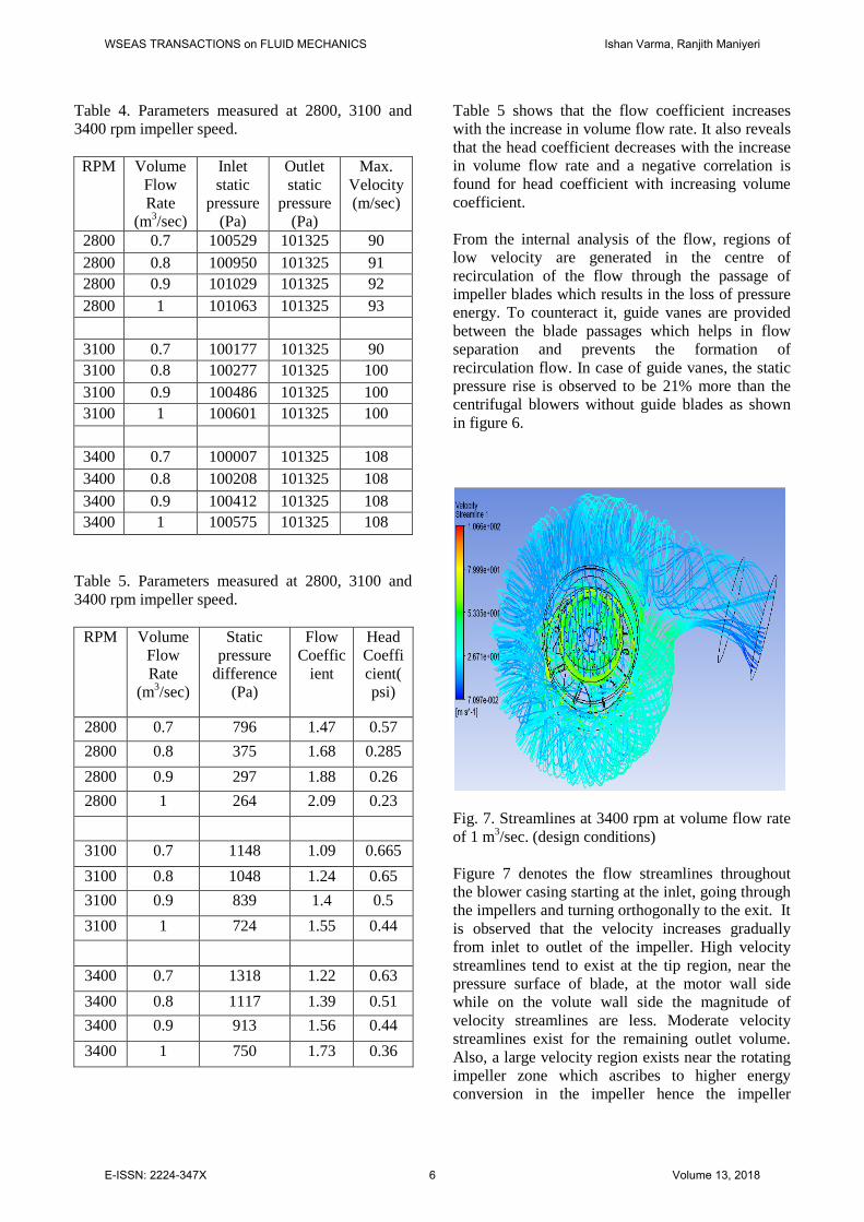
Table 4. Parameters measured at 2800, 3100 and 3400 rpm impeller speed. RPM Volume
Flow Rate
(m3/sec)
Inlet static
pressure (Pa)
Outlet static
pressure (Pa)
Max. Velocity (m/sec)
2800 0.7 100529 101325 90 2800 0.8 100950 101325 91 2800 0.9 101029 101325 92 2800 1 101063 101325 93
3100 0.7 100177 101325 90 3100 0.8 100277 101325 100 3100 0.9 100486 101325 100 3100 1 100601 101325 100
3400 0.7 100007 101325 108 3400 0.8 100208 101325 108 3400 0.9 100412 101325 108 3400 1 100575 101325 108
Table 5. Parameters measured at 2800, 3100 and 3400 rpm impeller speed.
RPM Volume Flow Rate
(m3/sec)
Static pressure
difference (Pa)
Flow Coeffic
ient
Head Coefficient(psi)
2800 0.7 796 1.47 0.57 2800 0.8 375 1.68 0.285 2800 0.9 297 1.88 0.26 2800 1 264 2.09 0.23
3100 0.7 1148 1.09 0.665 3100 0.8 1048 1.24 0.65 3100 0.9 839 1.4 0.5 3100 1 724 1.55 0.44
3400 0.7 1318 1.22 0.63 3400 0.8 1117 1.39 0.51 3400 0.9 913 1.56 0.44 3400 1 750 1.73 0.36
Table 5 shows that the flow coefficient increases with the increase in volume flow rate. It also reveals that the head coefficient decreases with the increase in volume flow rate and a negative correlation is found for head coefficient with increasing volume coefficient. From the internal analysis of the flow, regions of low velocity are generated in the centre of recirculation of the flow through the passage of impeller blades which results in the loss of pressure energy. To counteract it, guide vanes are provided between the blade passages which helps in flow separation and prevents the formation of recirculation flow. In case of guide vanes, the static pressure rise is observed to be 21% more than the centrifugal blowers without guide blades as shown in figure 6.
Fig. 7. Streamlines at 3400 rpm at volume flow rate of 1 m3/sec. (design conditions) Figure 7 denotes the flow streamlines throughout the blower casing starting at the inlet, going through the impellers and turning orthogonally to the exit. It is observed that the velocity increases gradually from inlet to outlet of the impeller. High velocity streamlines tend to exist at the tip region, near the pressure surface of blade, at the motor wall side while on the volute wall side the magnitude of velocity streamlines are less. Moderate velocity streamlines exist for the remaining outlet volume. Also, a large velocity region exists near the rotating impeller zone which ascribes to higher energy conversion in the impeller hence the impeller
WSEAS TRANSACTIONS on FLUID MECHANICS Ishan Varma, Ranjith Maniyeri
E-ISSN: 2224-347X 6 Volume 13, 2018
accounts for a major contribution in the total head developed. Reversal of the flow at the blower outlet is observed due to the large flow area at the casing exit owing to which velocity difference regions arise at the exit of the volute casing as seen in figure 7. At design conditions, large exit area helps in preventing the formation of the vortex. However, when the blower operates at off design conditions, eddy formation takes place within flow and offers resistance to the path of flow.
Fig. 8. Cut plane representing streamlines at 2800 rpm Figure 8 shows the cut plane of the blower system representing the characteristic velocity flow lines and pressure distribution. From the pressure contours and velocity streamlines it is observed that the distributions of velocity stream lines and pressure follows a similar pattern for the three rotational frequencies although the absolute value of each variable is different. At the designed flow rate, pattern of uniform distribution of velocity and static pressure exits at the circumferential regions of the outlet of impeller.
Fig. 9. Static pressure rise vs volume flow rate
From figure 9 it can be inferred that the gain in static pressure decreases with the increase in volume flow rate for all the rotation speeds of the impeller. It is also seen that the rise in static pressure difference across the centrifugal blower is directly proportionate to rotational speed till design conditions. Therefore, design of the impeller blade profile should be in conformance to a specific set of parameters.
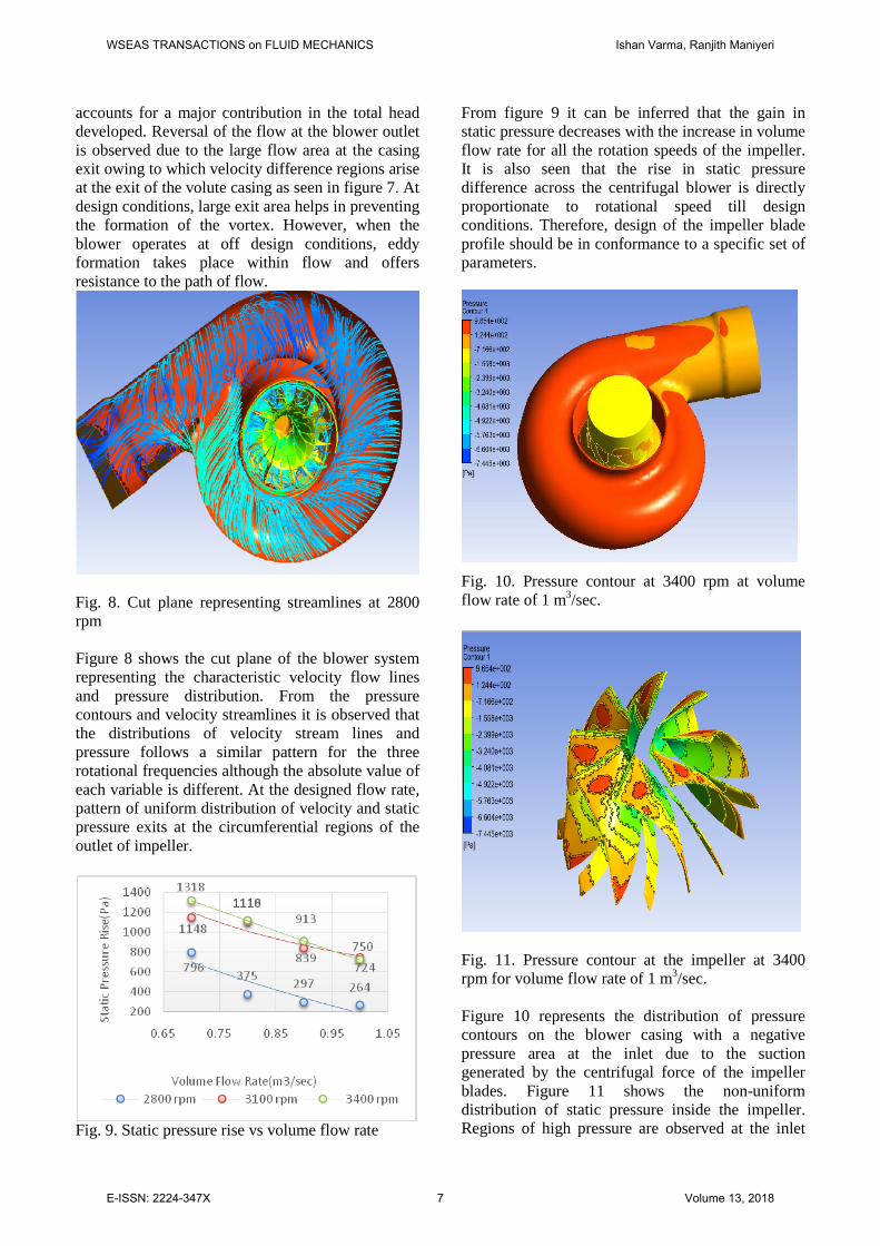
Fig. 10. Pressure contour at 3400 rpm at volume flow rate of 1 m3/sec.
Fig. 11. Pressure contour at the impeller at 3400 rpm for volume flow rate of 1 m3/sec. Figure 10 represents the distribution of pressure contours on the blower casing with a negative pressure area at the inlet due to the suction generated by the centrifugal force of the impeller blades. Figure 11 shows the non-uniform distribution of static pressure inside the impeller. Regions of high pressure are observed at the inlet
WSEAS TRANSACTIONS on FLUID MECHANICS Ishan Varma, Ranjith Maniyeri
E-ISSN: 2224-347X 7 Volume 13, 2018
and the pressure surface near the hub of impeller whereas low pressure regions are located at the suction surface near the hub. The variations in static pressure tends to diminish towards the outflow direction near the tip region of the impeller.
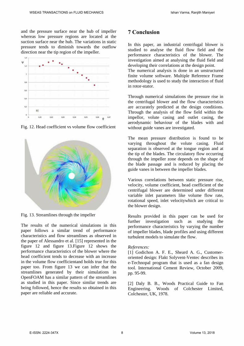
Fig. 12. Head coefficient vs volume flow coefficient
Fig. 13. Streamlines through the impeller The results of the numerical simulations in this paper follows a similar trend of performance characteristics and flow streamlines as observed in the paper of Alessandro et al. [15] represented in the figure 12 and figure 13.Figure 12 shows the performance characteristics of the blower where the head coefficient tends to decrease with an increase in the volume flow coefficientand holds true for this paper too. From figure 13 we can infer that the streamlines generated by their simulations in OpenFOAM has a similar pattern of the streamlines as studied in this paper. Since similar trends are being followed, hence the results so obtained in this paper are reliable and accurate.
7 Conclusion In this paper, an industrial centrifugal blower is studied to analyse the fluid flow field and the performance characteristics of the blower. The investigation aimed at analysing the fluid field and developing their correlations at the design point. The numerical analysis is done in an unstructured finite volume software. Multiple Reference Frame methodology is used to study the interaction of fluid in rotor-stator. Through numerical simulations the pressure rise in the centrifugal blower and the flow characteristics are accurately predicted at the design conditions. Through the analysis of the flow field within the impellor, volute casing and outlet casing, the aerodynamic behaviour of the blades with and without guide vanes are investigated. The mean pressure distribution is found to be varying throughout the volute casing. Fluid separation is observed at the tongue region and at the tip of the blades. The circulatory flow occurring through the impeller zone depends on the shape of the blade passage and is reduced by placing the guide vanes in between the impeller blades. Various correlations between static pressure rise, velocity, volume coefficient, head coefficient of the centrifugal blower are determined under different variable inlet parameters like volume flow rate, rotational speed, inlet velocitywhich are critical to the blower design. Results provided in this paper can be used for further investigation such as studying the performance characteristics by varying the number of impeller blades, blade profiles and using different turbulent models to simulate the flow.
References: [1] Godichon A. F. E., Sheard A. G., Customer-oriented design: Flakt Solyvent-Ventec describes its e-Technopal program that is used as a fan design tool. International Cement Review, October 2009, pp. 95-99. [2] Daly B. B., Woods Practical Guide to Fan Engineering. Woods of Colchester Limited, Colchester, UK, 1978.
WSEAS TRANSACTIONS on FLUID MECHANICS Ishan Varma, Ranjith Maniyeri
E-ISSN: 2224-347X 8 Volume 13, 2018
[3] Eck B., Fans: Design and Operation of Centrifugal, Axial-flow, and Cross-flow Fans. Pergamon Press Ltd, Oxford, UK, 1973. [4] Sheam-Chyun Lin, Ming-Lun Tsai. An integrated performance analysis for a backward-inclined centrifugal fan, Computers and Fluid, 56; 2011, pp. 24-38. [5] Pan D, Sakai T, Wilson M, Whitfield M, A computational and Experimental Evaluation of the Performance of a Centrifugal Fan Volute. Proceedings of I MECH E, Part A: Journal of Power and Energy 212(4), 1998, pp. 235-246. [6] Hassan M. B., Sardar A. and Ghias R., CFD simulations of an automotive HVAC blower operating under stable and unstable flow conditions, SAE International 2010. [7] Liu Zhengxian et al. Computational and Experimental Investigation of 3-D Turbulent Flow Field in centrifugal Impeller. Fluid machinery 28(4), 2000, pp. 9-12. [8] C.-M. Jang, D.-W. Kim and S.-Y. Lee, Performance characteristics of turbo blower in a refuse collecting system according to operation conditions, Journal of Mechanical Science and Technology, Volume 13, Issue 5, 2010, pp.58-63. [9] Shah K. H., Vibhakar N. N. and Channiwala S. A. Unified design and comparative performance evaluation of forward and backward curved radial tipped centrifugal fan, Proceedings of the International Conference on Mechanical Engineering 2003 (ICME2003), Dhaka, Bangladesh, 26- 28 December 2003. [10] Zhang M. J., Pomfret M. J., Wong C. M., Three-dimensional viscous flow simulation in a backswept centrifugal impeller at the design point. Computers and Fluids, 25(5), 1996, pp. 497-507. [11] Karanth K. V. and Sharma N. Y., Numerical analysis on the effect of varying number of diffuser vanes on impeller-diffuser flow interaction in a centrifugal fan, World Journal of Modeling and Simulation, Vol. 5, No. 1, 2009, pp. 63-71. [12] Karanth K. V. and Sharma N. Y., Numerical Analysis of a Centrifugal Fan for Improved Performance using Splitter Vanes, World Academy of Science, Engineering and Technology, 2009, pp. 453-459.
[13] V. M. Cherkassky, Pumps, Fans, Compressors, Mir Publishers, Moscow, 1977. [14] Launder B. E., Sharma B. I., Application of the energy-dissipation model of turbulence to the calculation of flow near a spinning disc. Letters in Heat and Mass Transfer, 1(2), 1974, pp. 131-137. [15] Ferziger J., Peric M., Computational Methods for Fluid Dynamics. Springer, 1997. DOI: 10.1007/978-3-642-97651-3
WSEAS TRANSACTIONS on FLUID MECHANICS Ishan Varma, Ranjith Maniyeri
E-ISSN: 2224-347X 9 Volume 13, 2018
Top Related