


Languages
Pages
Legal

The INL is a U.S. Department of Energy National Laboratoryoperated by Battelle Energy Alliance
INL/MIS-19-52979-Revision-0
Nuclear GraphiteComponents
William E Windes
April 2019
INL/MIS-19-52979-Revision-0
Nuclear Graphite Components
William E Windes
April 2019
Idaho National LaboratoryIdaho Falls, Idaho 83415
http://www.inl.gov
Prepared for theU.S. Department of Energy
Under DOE Idaho Operations OfficeContract DE-AC07-05ID14517

Nuclear Graphite Components
Will WindesART Graphite R&D Technical Lead
NRC HTGR Training April 16-17, 2019
Advanced Reactor TechnologiesIdaho National Laboratory

Graphite Outline
• Functions and Requirements Normal and off-normal component functions Key safety requirements of core components
• Graphite Manufacture Unique material properties of graphite Ideal unirradiated material properties – it’s not metal
• Environmental effects on nuclear graphite Effects of oxidation
• It doesn’t burn! Effects of irradiation of graphite
• No Wigner (stored) energy if operated above 300°C• Physical, thermal, and mechanical properties• Turnaround and creep significance explained
• ASME Code for Graphite Core Components New ASME code: probabilistic (ceramics) vs. deterministic (metals) How environmental effects are accounted for in design requirements
• Operating considerations (prismatic vs. pebble vs. molten salt) Differences between different graphite core designs 2

Critical Safety Requirements• Maintain core geometry and structural integrity
Maintain fuel configuration during all operations (normal and off-normal) Maintain undisturbed access for the insertion of reactivity control material Maintain proper core coolant configuration
• No blockage of coolant pathway • No gaps between graphite components
• Protection of fuel Compacts within the prismatic fuel elements Pebbles within the core center
• Passively remove core heat during off-normal events Rapidly absorb large thermal transients Primarily by radial conduction from the fuel to the core barrel
• During off-normal events when forced cooling is not available
• How does it do this?: Graphite does NOT melt or burn Graphite DOES have high thermal conductivity and thermal stability Relatively strong in compression, weak in tension.
3

Graphite Manufacture• All graphite grades are proprietary. Only
limited/general fabrication data is known.• Unique manufacturing processes for graphite
must be understood to appreciate graphite behavior Graphite is a porous material (15-20%) - By
design! Porosity provides thermal and irradiation
stability
• Graphite is manufactured from calcined coke and a pitch binder. Multiple pitch impregnations to increase density
• Green forming technique influences the final microstructure Desire isotropic (or near isotropic) material
response
• Properties and performance of graphite are significantly influenced by both raw materials and processing Nuclear graphite undergoes further purification
steps4

Graphite Material Properties of Interest
From ASTM D7219 : Standard Specification for Isotropic and Near-isotropic Nuclear Graphites• Density
Higher = Stronger Lower = Better irradiation performance
• Conductivity Nearly a 70% drop almost immediately after reactor
startup
Property Nominal Range Performance Attributes
Density 1.7 - 1.9 g/cm3 Neutron efficiency, Structural integrity, Thermal efficiency
Thermal Conductivity (at Room Temperature)
> 90 W/m/KHeat transport
Purity (Total Ash Content) < 300 ppmReduced component activity levels during replacement and/or disposal
Reduced graphite oxidation under normal and accident conditions.
Tensile Strength > 15 MPa Structural integrity
Compressive Strength > 45 MPa Structural integrity
Flexural Strength > 20 MPa Structural integrity
CTE (20°C to 500°C) 3.5 to 5.5 x 10⁻⁶ K-1
High value is indication of isotropy = dimensional stability under irradiation
Lower value potentially beneficial in terms of thermal stress
CTE Isotropy Ratio < 1.10Irradiation dimensional stability
Structural integrity
Dynamic Elastic Modulus 8 – 15 GPaStructural integrity
Irradiation creep
Dimensional Changes with Irradiation
Minimal shrinkage
Minimal differences in with-grain and against-grain directions
Structural integrity (lower internal stresses)
• CTE (Coefficient of Thermal Expansion) Indicates isotropy and needed for gas gap analysis
• Purity Requires additional heat treatment
• Dimensional changes Affects structural integrity If internal stress exceeds inherent strength of
graphite = cracks5

Graphite “Burning” and dust “Explosions”
• Graphite can not burn – just physically can not sustain self oxidation Fire needs Heat, fuel, and oxygen Fuel (carbon) is restricted to only the edges. Oxygen is restricted by the crystallography. Self-sustained oxidation (better definition than simple burning) can not be sustained.
• Graphite dust can not explode It does rapidly react but it self-suppresses. Similar mechanisms for “burning” Initial flare up of surface layer on dust particles – but then nothing.
• No chain reaction 6

Graphite “Burning” and dust “Explosions”
Graphite Dust
Graphite
Corn (Maize) Dust
Corn
Acheson
White hot graphite from furnace
7

Graphite Oxidation and “Burning”• Graphite can and does oxidize – high temperatures
8
Increasing grain size
• Needs continuous oxygen and temperatures above 200°C – 300°C Temperatures > 400°C needed for more rapid acute
oxidation (accidents) Temperatures < 400°C can still oxidize but at very slow
rates (chronic oxidation)• Oxidation still restricted to edges of crystallites with
porosity dictating oxygen transport into component
• Oxidation rates of different grades can be compared using ASTM D7542 standard, “Air Oxidation of Manufactured Carbon and Graphite in Kinetic Regime” Grain size dependent Oxidation of small grain grade >>
than large grain size

Irradiation Effects on Graphite Properties
• Irradiation induced changes must be considered in design• Significant changes occur during normal operation in:
Component dimensions• Components actually shrink …• Until Turnaround when they begin to expand until failure
Density• Components become more dense …• After Turnaround dose they decrease in density
Strength and modulus• Graphite gets stronger with irradiation …• Until Turnaround dose is achieved. It then decreases
Thermal conductivity• Decreases almost immediately to ~30% of unirradiated values
Coefficient of thermal expansion• Initially increases but then reduces after Turnaround until saturation
• Significant changes do not typically occur in the following properties: Oxidation rate, neutron moderation, specific heat capacity, emissivity
• No Wigner energy release if components irradiated above 300°C.
9

Irradiation-Induced Dimensional Changes
• Under neutron irradiation graphite components shrink (densify) – stop at Turnaround – then begin to expand (crack formation) Change is dose dependent: Higher doses = larger change Rate of change is highly temperature dependent Rate and amount of change is grade specific
• Results in tremendous internal stresses formed within graphite Crack formation and component failure – usually after Turnaround Isotropic response is desired to assist in prediction of stresses and dimensional changes
-4
-2
0
2
4
6
8
10
12
14
0 5 10 15 20 25
∆L/L
[%]
dose, dpa
1100 C
900 C
700 C
500 C
300 C
10

Irradiation-Induced Strength/Modulus Changes
• Changes in strength and modulus somewhat parallel dimensional changes
• Strength/modulus initially increase Maximum value is reached at
approximately the Turnaround dose
• After Turnaround pores start to form in microstructure As porosity forms, strength and modulus
fall at increasing rate• As with dimensional changes, strong
dependence on irradiation temperature
0
0.5
1
1.5
2
2.5
0 5 10 15 20 25
Tens
ile s
tren
gth,
σ/σ
o
dose, dpa
400 C500 C700 C900 C1100 C
11

Irradiation-Induced Thermal Conductivity Changes
• Initial steep drop in conductivity followed by a saturation level Point defects interrupt thermal diffusivity/conductance Efficiency of recombination rate of point defects is dependent upon irradiation
temperature = saturation Further degradation of conductivity due to larger microstructure defects
• Pore generation after turnaround
• At high operating temperatures irradiated and non-irradiated thermal diffusivity differences are small 12
0
20
40
60
80
100
120
140
160
0 100 200 300 400 500 600 700 800 900 1000
Cond
uctiv
ity, W
/m-K
Temperature, C
Non-irradiated
Ti=950, 6 dpa

Irradiation-Induced CTE Changes
• Overall, graphite CTE is low compared to other structural materials, e.g., metals Implies excellent shock
resistance• Along with dimensional
changes, must be accounted for in the design
• Initial increase with dose as manufacturing-related microcracks are closed Limited dependence on
Turnaround• Subsequent reduction of
CTE at increased dose rate0.4
0.5
0.6
0.7
0.8
0.9
1
1.1
1.2
1.3
1.4
0 5 10 15 20 25
CTE/
CTE o
dose, dpa
300 C
500 C
700 C
900 C
1100 C
13

Irradiation Creep
(Residual stress remover)
Irradiation Dimensional
Change
Dose, dpa
Irradiation Creep – Life Limiting Mechanism
• Reduces internal stresses resulting from dimensional changes
• Creep strain rate generally increases with temperature
• The net effect is positive in that stresses associated with dimensional changes and differential thermal expansion under irradiation are reduced
• As the total fluence (dose) is increased, this effect becomes increasingly important in attaining acceptable design lifetimes.
14

• ASME Code for Graphite Core approved by ASME BNCS in early-2010 Developed by Section III Subgroup on Graphite Core
Components First published in 2012 under Section III, Division 5
(High-Temperature Reactors)• Key features:
Applies to fuel, reflector and shielding blocks, plus interconnecting dowels and keys;
• Excludes fuel compacts and pebbles Rules apply to both individual components and
assemblies Applies probabilistic design methods Design must account for statistical variations in graphite
properties within billets and for different production runs Design must account for irradiation effects on graphite
properties Allowance of cracks in graphite components, provided
that safety functions are retained
15
ASME Code for Graphite Core Components
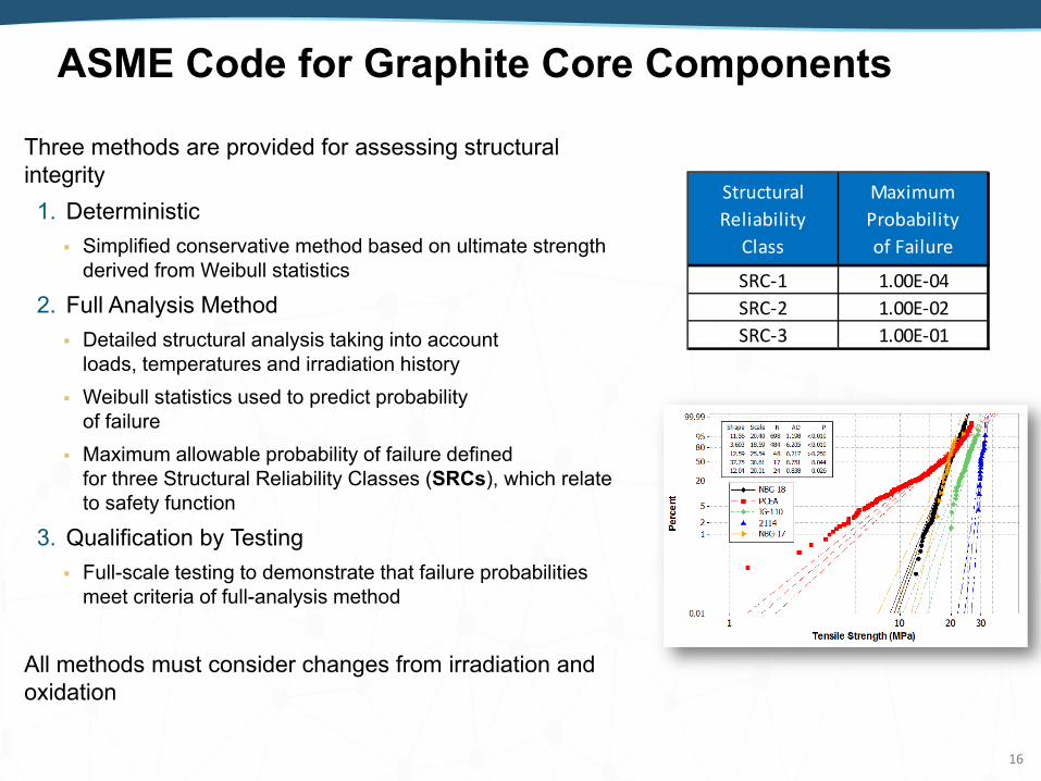
Three methods are provided for assessing structural integrity1. Deterministic Simplified conservative method based on ultimate strength
derived from Weibull statistics
2. Full Analysis Method Detailed structural analysis taking into account
loads, temperatures and irradiation history Weibull statistics used to predict probability
of failure Maximum allowable probability of failure defined
for three Structural Reliability Classes (SRCs), which relate to safety function
3. Qualification by Testing Full-scale testing to demonstrate that failure probabilities
meet criteria of full-analysis method
All methods must consider changes from irradiation and oxidation
StructuralReliability
Class
MaximumProbabilityof Failure
SRC-1 1.00E-04SRC-2 1.00E-02SRC-3 1.00E-01
16
ASME Code for Graphite Core Components

• New grades (third generation) are consistent and ready for codification Lack of quantitative data on graphite behavior at
higher temperature and dose applications Test data is needed to define how precursor
material changes, fabrication, and microstructure changes will affect performance
• Probablistic verses deterministic design approach Deterministic is too limiting for a brittle material A distribution of possible strengths in a material
is needed for quasi-brittle materials (i.e., flaw size for graphite)From Dr. Mark Mitchell – PBMR Inc.
ASME Code for Graphite Core Components
17
• Some amount of failure (i.e., a crack) is certain – graphite is porous The core needs to be designed to accept some amount of
failure Probability of failure based upon overlap of applied stresses and
graphite strength• Irradiation and oxidation effects must be addressed

When do you replace the graphite?
∆V/V
DoseMost Conservative Dose Level
More Risk but some Rx do operate here
Highest Risk
Operational Considerations – Operational Life
18

Operational Lifetime ConsiderationsPebble Bed
• Highest component lifetime dose What is expected lifetime dose? Turnaround dose? After Turnaround?
• Continuous operation Inspection of components is problematic Component replacement is difficult
• Components in high-fluence regions should be designed for replacement Will require shutdown and de-fueling of
pebbles from core• Large grain grades are possible
Higher Turnaround dose than fine grain Lower oxidation rates than fine grain
• Irradiated test data validating models will be required Currently only limited irradiation data for
newer nuclear grades Design life to be appropriately adjusted
as data become available.• Dust?
19
Prismatic• Lower component lifetime dose
Still need expected lifetime dose
• Periodic shutdown Much easier to inspect components Components in high-fluence regions can be
replaced or shuffled
• Finer grain grades required Webbing between fuel/coolant channels
requires smaller grain size Slightly lower Turnaround dose Higher oxidation rate
• Still requires irradiated test data to validate operational models Currently only limited irradiation data for
newer nuclear grades Design life to be appropriately adjusted
as data become available
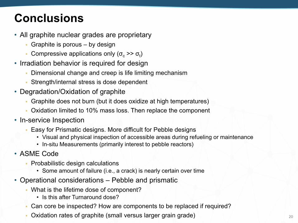
Conclusions• All graphite nuclear grades are proprietary
Graphite is porous – by design Compressive applications only (σc >> σt)
• Irradiation behavior is required for design Dimensional change and creep is life limiting mechanism Strength/internal stress is dose dependent
• Degradation/Oxidation of graphite Graphite does not burn (but it does oxidize at high temperatures) Oxidation limited to 10% mass loss. Then replace the component
• In-service Inspection Easy for Prismatic designs. More difficult for Pebble designs
• Visual and physical inspection of accessible areas during refueling or maintenance• In-situ Measurements (primarily interest to pebble reactors)
• ASME Code Probabilistic design calculations
• Some amount of failure (i.e., a crack) is nearly certain over time• Operational considerations – Pebble and prismatic
What is the lifetime dose of component?• Is this after Turnaround dose?
Can core be inspected? How are components to be replaced if required? Oxidation rates of graphite (small versus larger grain grade) 20

Suggested Reading• Manufacturing
ASTM D7219, Standard Specification for Isotropic and Near-isotropic Nuclear Graphites. Kelly, B. T., 1981, Physics of Graphite, Applied Sciences Publishers LTD, London U.K. and New Jersey USA, 1981. R.E. Nightingale, 1962, Nuclear Graphite, Academic Press, ISBN: 978-1-4832-2854-9.
• Oxidation International Atomic Energy Agency, 1992, INSAG 7, “The Chernobyl Accident: Updating of INSAG 1, International
Nuclear Safety Advisory Group, IAEA, Safety Series No. 75 INSAG 7, (ISBN: 9201046928), 1992. Cristian I. Contescu, Robert W Mee, Yoonjo (Jo Jo) Lee, Jose D Arregui-Mena, Nidia C Gallego, Timothy D Burchell,
Joshua J Kane, William E Windes, “Beyond the Classical Kinetic Model for Chronic Graphite Oxidation by Moisture in High Temperature Gas-Cooled Reactors”, Carbon, 127 (2018) 158-169.
Joshua J. Kane, Cristian I. Contescu, Rebecca E. Smith, Gerhard Strydom, and William E. Windes, “Understanding the Reaction of Nuclear Graphite with Molecular Oxygen: Kinetics, Transport, and Structural Evolution", Journal of Nuclear Materials, Volume 493, September 2017, Pages 343–367.
Windes, W., G. Strydom, R. Smith, and J. Kane, 2014, “Role of Nuclear Grade Graphite in Controlling Oxidation in Modular HTGRs,” INL/EXT-14-31720, Rev. 0, November 2014.
Laine, N. R., Vastola, F. J., and Walker Jr., P.L., 1963, “The importance of active surface area in the carbon oxygen reaction,” J Phys Chem, Vol. 67, pp. 2030–2034.
Walker Jr., P. L., Rusinko, F., and Austin, L. G., 1958, “Gas Reactions of Carbon,” Advances in Catalysis, Vol. 11, pp. 133–221.
Bradbury, D., Wickham, A., Graphite Decommissioning: Options for graphite treatment, recycling, or disposal, including a discussion of safety related issues, EPRI Technical Report 1013091, March 2006.
Walker Jr., P. L., 1990, “Carbon: An old but new material revisited,” Carbon, Vol. 28, pp. 261–279. Walker Jr., P. L., Taylor, T. L., and Ranish, J. M., 1991, “An update on the graphite-oxygen reaction,” Carbon, Vol. 29,
pp. 411–421.
21

Suggested Reading (cont.)• Dust
Bradbury, D., Wickham, A., Graphite Decommissioning: Options for graphite treatment, recycling, or disposal, including a discussion of safety related issues, EPRI Technical Report 1013091, March 2006.
P. W. Humrickhouse, HTGR Dust Safety Issues and Needs for Research and Development, INL/EXT-11-21097, June 2011.
A. Bentaib & J. Vendel, ITER Project: Dust Mobilization and Explosion, Introductory Meeting on the Planned PSI Research Project on HTR Graphite Dust Issues, PSI, Villigen, 26-27 November 2009.
• Irradiation Effects J. H. W. Simmons, Radiation Damage in Graphite: International Series of Monographs in Nuclear Energy, Elsevier publications,
2013, ISBN: 1483186490
Kelly, B. T., 1981, Physics of Graphite, Applied Sciences Publishers LTD, London U.K. and New Jersey, USA, 1981.
R.E. Nightingale, 1962, Nuclear Graphite, Academic Press, ISBN: 978-1-4832-2854-9.
Idaho National Laboratory, NGNP High Temperature Materials White Paper, INL/EXT-09-17187 R1, August 2012.
N. C. Gallego and T. D. Burchell, A Review of Stored Energy Release of Irradiated Graphite, ORNL/TM-2011/378, September 2011.
• ASME Code and Licensing 2017 ASME Boiler and Pressure Vessel Code: An International Code, SECTION III: Rules for Construction of Nuclear Facility
Components, Division 5: High Temperature Reactors, ASME BPVC.III.5-2017.
G. Longoni, R.O. Gates, B.K. Mcdowell, High Temperature Gas Reactors: Assessment of Applicable Codes and Standards, PNNL-20869 Rev. 1, October 2015.
Mitch Plummer and Andrea Mack, Graphite Characterization: Baseline Variability Analysis Report, INL/EXT 18 45315, June 2018.
Timothy D Burchell, Rob Bratton, Barry Marsden, Makuteswara Srinivasan, Scott Penfield, Mark Mitchell, Will Windes, Next Generation Nuclear Plant Phenomena Identification and Ranking Tables (PIRTs) Volume 5: Graphite PIRTs, NUREG/CR-6944, Vol. 5, 2007, Washington, DC USA.
AB Hull, S. Malik, M. Srinivasan, and R. Tregoning, Survey of NRC’s Materials Research Associated with Advanced Reactors, Proceedings from Corrosion 2012 Research Topical Symposium on Corrosion Degradation of Materials in Nuclear Power Reactors – Lessons Learned and Future Challenges, Salt Lake City, Utah, March 11-15, 2012. 22

Suggested Reading (cont.)
• ASME Code and Licensing Noel N. Nemetha and Robert L. Bratton, Overview of statistical models of fracture for
nonirradiated nuclear-graphite component, Nuclear Engineering and Design, 2010, Vol 240, pp. 1-29.
S.F. Duffy and A. Parikh, Quality Control Using Inferential Statistics in Weibull-Based Reliability Analysis, ASTM International Technical Papers: Graphite Testing for Nuclear Applications, STP 1578, pp. 105-122.
M. Srinivasan, The Use of Small Graphite Specimen Test Data for Large Core Components for HTGR, ASTM International Technical Papers: Graphite Testing for Nuclear Applications, STP 1578, pp. 30-64.
Xiang Fang, Haitao Wang, and Suyuan Yu, The Stress and Reliability Analysis of HTR’s Graphite Component, Science and Technology of Nuclear Installations, Volume 2014, http://dx.doi.org/10.1155/2014/964848.
D. Kanse, I. A. Khan, V. Bhasin, and R. K. Singh, Interpretation of ASME Code Rules for Assessment of Graphite Components, SMiRT-23 Division II Paper ID 346, Manchester, United Kingdom - August 10-14, 2015.
23

2424

Source-dependence on graphite properties• There is no generic “nuclear grade” graphite that can be made by all vendors
All nuclear graphite grades are proprietary. How they are made is secret to the individual vendor.
• Completely different than metals. There is no fabrication information available for any grade. Graphite users must select the grades that match their specific requirements. And no, vendors wont give up their recipes. There is no customer base asking for it.
• As discussed in fabrication slide the unique graphite manufacturing processes dictate the graphite behavior – both unirradiated and irradiated. Main fabrication parameters are:
• coke source: petroleum or coal-based coke source• grain size: coke particles (grains) range in size from 1800 μm to 15 μm• fabrication method: iso-static molded, vibration molded, or extruded fabrication• Grain-binder ratio: the amount of carbonaceous binder added to the grain particles
Modifying these parameters can dramatically alter the unirradiated material properties and irradiation performance.
25
Parameter Unirradiated Behavior Irradiated Behavior
Increased Density Increased strength and modulusHigher fracture strength
A general decrease in Turnaround dose• Shorter component lifetime
Isostatic fabrication Higher isotropy (than extruded)Higher cost material
Better, more predictable, irradiation performance.
Smaller grain size More uniform, finer microstructure• Especially when isostatic molded
Higher oxidation rate than larger grained
Super-fine grades may have lower Turnaround dose

Minimal effects to graphite from irradiation• No significant changes occurs in:
Neutron moderation – Carbon atoms not removed Specific heat capacity – Crystal structure remains intact Oxidation rate - Minimal changes if any due to densification during irradiation. Molten salt interaction – Graphite behavior (unirr. and irr.) similar to gas-cooled
• Physical damage possible from salt intrusion into pores in graphite components
26
Emissivity:• Unaffected by irradiation but oxidation
may leave impurity oxides on outer surface.
Ti = 150°C
Ti = 200°C
Ti = 250°C
Rate
of s
tore
d en
ergy
rele
ase,
ds/
dT, J
/g∙°C
• Minimal Wigner energy release if components irradiated above 300°C. Annealing of point defects in graphite is
rapid above 250°C Minimal accumulation of stored energy
• Need high dose & low Ti Low dose/low Ti components have
reduced risk

Graphite Component Failure
27
• What do we mean by structural integrity U.K.’s AGR bricks – Now past Turnaround dose
• Example of graphite component failure. Both axial as well as radial cracking in components
• Lifetime is completely dependent upon graphite core now Not fuel design/performance, metallic internals, or
secondary systems
360°
AGR Core components

Graphite Component Failure
28
• CAUTION! U.K. AGR uses CO2 for coolant Radiolytic oxidation exacerbates all strength changes
• Inert gas cooled designs will be more robust Component strength, internal stresses, and POF will
be much different than CO2 cooled AGRs
360°
AGR Core componentsFrom: J. Reed, Summary of Recent Inspection Data at UK Advanced Gas Cooled Reactors with Implications for Assessment of Graphite Component Integrity, INGSM-17, 4–8 September 2016, IAEA, Vienna, Austria
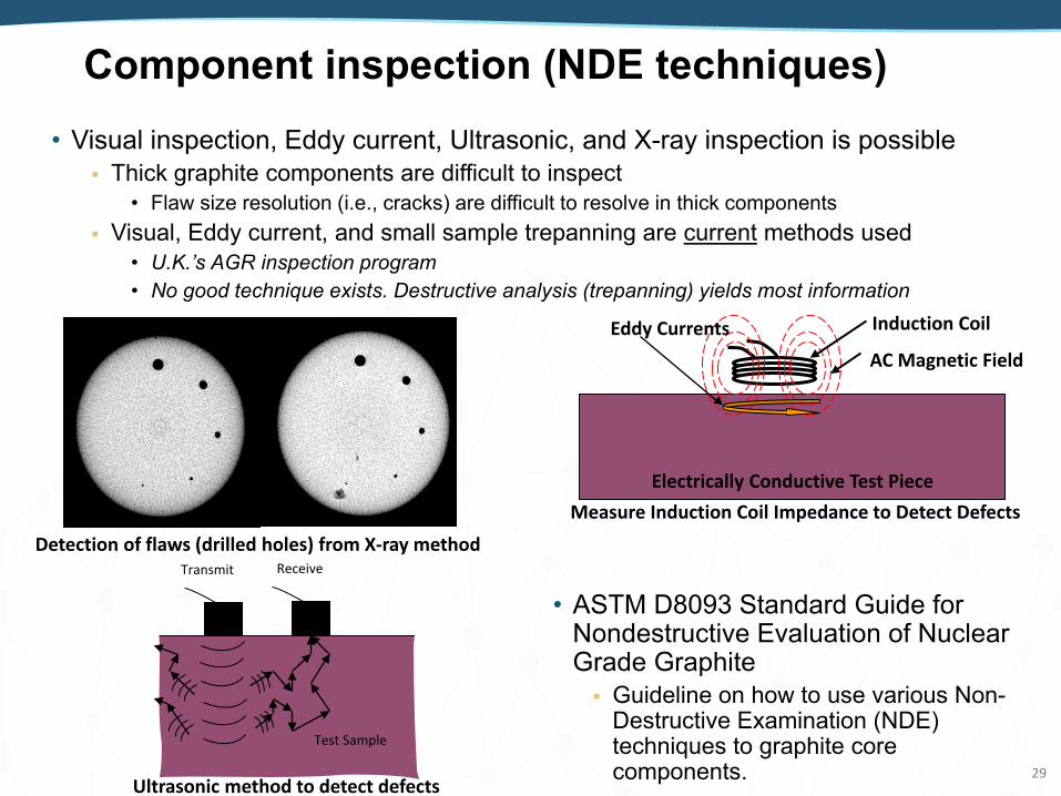
Component inspection (NDE techniques)• Visual inspection, Eddy current, Ultrasonic, and X-ray inspection is possible
Thick graphite components are difficult to inspect• Flaw size resolution (i.e., cracks) are difficult to resolve in thick components
Visual, Eddy current, and small sample trepanning are current methods used • U.K.’s AGR inspection program• No good technique exists. Destructive analysis (trepanning) yields most information
29
Induction Coil
AC Magnetic FieldEddy Currents
Electrically Conductive Test PieceMeasure Induction Coil Impedance to Detect Defects
• ASTM D8093 Standard Guide for Nondestructive Evaluation of Nuclear Grade Graphite Guideline on how to use various Non-
Destructive Examination (NDE) techniques to graphite core components.
Test Sample
Transmit Receive
Ultrasonic method to detect defects
Detection of flaws (drilled holes) from X-ray method

ASME code methodology for graphite - 1• Two key points to keep in mind:
1. All nuclear graphite is proprietary – Specific fabrication recipes are unknown• The properties for each grade are highly dependent on the recipe and are optimized
(altered) to suit each users requirements.2. Graphite is brittle (quasi-brittle).
• Metals are ductile giving them the ability to fail in a predictable manner.• Graphite fails much like ceramic – Probability of failure (POF) due to flaw size distributions• Weibull analysis historically used to predict the probability of failure and characteristic
strength of brittle and flaw dependent materials.
• Consequently, there are no “standard” specifications such as metals have ASTM D7219 specifies impurity levels only. Other properties are desired ranges. It’s like specifying “Stainless steel” for a component (not 304, 316, or 316L)
• The selected grade is then fabricated to the specific requirements of component• However, not much variation over all the grades. Not like metals
• KIc ~ 0.5 – 1.5 Pa∙√m, σt = 15-30 MPa, 4.5 – 5.5 x 10⁻⁶, etc.
• Thus, graphite code is a “process” vs just picking a preapproved material The reactor applicant must demonstrate the graphite grade selected will consistently
meet the component requirements.• Requires property testing and analysis of the material properties before is durability as a
nuclear component is analyzed.• Achieved through the “Material Data Sheets” required in Code.
• Weibull parameters from strength tests used to predict the probability of failure of graphite. • Data used in both “simple” (deterministic) and “full” (probabilistic) determination
30

ASME code methodology for graphite -2• Fundamental material properties change with irradiation/oxidation
Code must assess changes to design of component due to these changes• Irradiation: changes to density, strength, dimension, CTE, thermal conductivity• Oxidation: changes in density, strength, CTE, and thermal conductivity.
Code must also address these changes to in service and inspection• NDE and ISI are still outstanding issues that need to be addressed for graphite
• Material testing and analysis must be performed to determine changes Property changes and irradiation creep to maximum expected dose levels. Oxidation rates, property changes, and strength assessment to maximum expected
oxidation levels• Expected degradation during off-normal events with high temperatures and oxygen ingress
• Behavior and performance prediction models based upon irradiation and oxidation experimental results. Property degradation due to oxidation, irradiation, and dimensional stress buildup. Fracture behavior and structural integrity = Primary 31

Summary of Simplified Graphite AssessmentSimple Assessment: 2 parameter Weibull (Deterministic Analysis)
Perform a stress analysis of the graphite component
Cm = Combined Membrane StressCb = Combined Bending StressF = Peak StressRtf = ratio of flexural to tensile strength
Estimate the scale and shape of a 2 parameter Weibull using a linear fit to measured property data
m* and Sc*
Evaluate the acceptability of the design
- Cm < Sg(P)- Cm + Cb + F < Rtf * Sg(P)
Sg(P) , Rtf
Using m* and Sc*
determine the Weibull parameters corresponding to a 95% confidence interval
m95% and Sc95%
Using m95% and Sc95%determine the “design allowable stress” as a function of POF = 10-4, 10-3, 10-2 and 5x10⁻²
from SRCs
Sg(P)
(ref. HHA-3215 pg. 392 and HHA-3216 pg. 393)
(ref. HHA-II-3100 pg. 414)(ref. eq.6 and eq.7 pg. 417) (ref. HHA-II-3300 pg. 418)
(ref. HHA-3220 pg. 394)
Calculate the ratio of
flexural to tensile
strength
Rtf(Ref.HHA-II-2000
pg. 412)

Summary of Full Graphite Assessment
33
Full Assessment: 3 parameter Weibull (Probabilistic Analysis)Define the “Material Reliability Curve” by fitting a 3 parameter Weibull model to the measurement data.
Estimate 3 parameter Weibull parameters using MLE’s .(So, m095% and Sc095%)
Calculate the POF of the graphite core component using the “Material Reliability Curve” and stress distribution in the component.
Evaluate the acceptability of the design
POFcomponent < POFallowable
Determine the allowable POF from the Structural Reliability Class (SRC), and Service Level Design Loading.
POFallowable ≤ 10-2 and ≥ 10-4
POFcomponent
(ref. HHA-II-3200 pg. 417) (ref. HHA-3217 pg. 393)
(ref. HHA-3230 thru HHA-3237 pg. 397)

ASME Code modifications (Roadmap)• Corrosion rate variability within a nuclear grade
Oxidation test specimens should require testing specimen be selected at different locations within a billet, over multiple billets, and over multiple batches.
• This will provide the oxidation rate variability across the entire specific grade Currently the oxidation mass loss for a component is limited to 10 wt%.
• After 10 wt% the component is recommended to be replaced.• Code needs to provide guidance on how the oxidation mass loss is applied.
• Averaged over entire core? Only in central core region? Or only for select components?
• High temperature mechanical testing isn’t really necessary for graphite As noted mechanical strength and modulus increase with increasing temperature. Room temperature results are conservative for graphite No elevated temperature testing standards exist to support this current requirement
• (i.e., no ASTM standards) How is elevated temperature testing of irradiated material to be conducted?
• Testing temperatures at (or above) Tirr will anneal out irradiation effects
• Mechanical testing of irradiated material is unnecessary up to Turnaround As noted mechanical strength and modulus increase with increasing dose – until
Turnaround dose has been reached. Room Temperature/unirradiated mechanical testing is conservative until Turnaround
dose has been achieved. If components will be used to dose levels above Turnaround (i.e., high dose levels)
extensive testing will be required 34
Top Related