


Languages
Pages
Legal


SRF No. 9428
November 9, 2017
ADDENDUM 1 – JOB 47
TO: All prospective bidders on project TAU-8-984(154)157, Job No. 47 scheduled for the November
17, 2017 bid opening.
Addendum 1 is to address: Revising special provisions. Adding landscape boulders to protect path wall.
Updating bridge quantities, details, notes.
The following plan and proposal revisions shall be made:
Proposal Revisions:
Remove and replace SP 5182(14) Permits and Environmental Considerations with the enclosed SP
5182(14) revised 11/8/17.
Remove and replace SP 553(14) Architectural Finish and Stain with the enclosed SP 553(14) revised
10/19/17.
Remove SP 554(14) Anti-Graffiti Coating
Remove and replace SP 555(14) Hoist System with the enclosed SP 555(14) revised 10/19/17.
Plan Revisions:
Remove and replace sheets 170-1 to 12 with the enclosed sheets revised 11/6/17.
Remove and replace sheet 20-3 with the enclosed sheet revised 11/7/17.
Remove and replace sheets 2-1, 4-1, 6-1 to 2, 8-1, and 60-1 to 3 with the enclosed sheets revised
11/8/17.
Add sheet 20-5 with the enclosed sheet added 11/8/17.
Sheet 2-1:
Removed SP 554(14) Anti-Graffiti Coating. Combined with SP 553(14) Architectural Finish and
Stain. Added sheet 20-5.
Sheet 4-1:
Revised to show Landscaping Appurtenances (Boulders).
Sheet 6-1:
Revised Note 750-P01 to differentiate contraction joint widths between 10’ path and 18’ 8th St
pavement.
Sheet 6-2:
Added note for “Landscaping Appurtenances” to describe work and payment for landscape boulders.
Sheet 8-1:
Increased 612 0115 Reinforcing Steel-Grade 60 from 7600 LBS to 9420 LBS
Decreased 612 0116 Reinforcing Steel-Grade 60-Epoxy Coated from 19720 LBS to 18880 LBS
Increased 622 0020 Steel Piling HP 10 X 42 from 2520 LF to 2730 LF
Added bid item 970 0001 Landscaping Appurtenances 1 LS
Removed bid item 930 9930 Anti-Graffiti Coating


SpecNo.
Amount
Description UnitApprox.Quantity
Unit Price
$$$$$ 000 $$$$$ 00
PROPOSAL FORMNorth Dakota Department of Transportation
047Page 6 of 9
11/9/2017
JobNovember 17, 2017BID OPENING:
CodeNo.
Bidder must type or neatly print unit prices in numerals, make extensions for each item, and total. Do not carry unit prices further than three (3) decimal places.
ItemNo.
Project: TAU-8-984(154)157 (PCN-21690)
Rev: BID ITEMS
HYDRAULIC MULCH 320.017 253 0201 ACRE
RIPRAP GRADE II 191.018 256 0200 CY
FIBER ROLLS 12IN 684.019 261 0112 LF
REMOVE FIBER ROLLS 12IN 684.020 261 0113 LF
FLOTATION SILT CURTAIN 266.021 262 0100 LF
REMOVE FLOTATION SILT CURTAIN 266.022 262 0101 LF
AGGREGATE BASE COURSE CL 5 84.023 302 0121 CY
CLASS AE-3 CONCRETE 180.024 602 1130 CY
REINFORCING STEEL-GRADE 60 9,420.025 612 0115 LBS
REINFORCING STEEL-GRADE 60-EPOXY COATED 18,880.026 612 0116 LBS
STRUCTURAL STEEL 55,320.027 616 0360 LBS
STEEL PILING HP 10 X 42 2,730.028 622 0020 LF
STEEL SHEET PILING 1,690.029 622 6760 SF
PEDESTRIAN FENCE 72.030 624 0124 LF
MOBILIZATION 1.031 702 0100 L SUM
TRAFFIC CONTROL SIGNS 260.032 704 1000 UNIT

SpecNo.
Amount
Description UnitApprox.Quantity
Unit Price
$$$$$ 000 $$$$$ 00
PROPOSAL FORMNorth Dakota Department of Transportation
047Page 7 of 9
11/9/2017
JobNovember 17, 2017BID OPENING:
CodeNo.
Bidder must type or neatly print unit prices in numerals, make extensions for each item, and total. Do not carry unit prices further than three (3) decimal places.
ItemNo.
Project: TAU-8-984(154)157 (PCN-21690)
Rev: BID ITEMS
TYPE III BARRICADE 8.033 704 1052 EA
GEOTEXTILE FABRIC-TYPE RR 375.034 709 0600 SY
PIGMENTED IMPRINTED CONCRETE 18.035 750 0030 SY
SIDEWALK CONCRETE 4IN 698.036 750 0115 SY
FENCE CHAIN LINK 872.037 752 0600 LF
VEHICLE GATE 2.038 752 2100 EA
REMOVE VEHICLE GATE 2.039 752 2120 EA
BRIDGE BENCH MARKS 1.040 930 3000 SET
RELOCATE TRUSS BRIDGE 1.041 930 9677 L SUM
PEDESTRIAN BRIDGE - PRE-FAB 1.042 930 9750 EA
LANDSCAPING APPURTENANCES 1.043 970 0001 L SUM
TREES 20.044 970 1000 EA
ELECTRICAL SERVICE 1.045 990 0730 L SUM
TOTAL SUM BID

SP 553(14) Page 1 of 2
NORTH DAKOTA DEPARTMENT OF TRANSPORTATION
SPECIAL PROVISION
ARCHITECTURAL FINISH AND STAIN
PROJECT 8-984(154)157 – PCN 21690
DESCRIPTION This work consists of applying concrete stain and anti-graffiti coating to all exposed concrete surfaces. MATERIALS A. General.
Obtain all concrete stain and anti-graffiti products from a single source. B. Stain.
Provide a 100 percent acrylic; water-repellant, semi-opaque, tinted emulsion sealer designed for concrete and masonry surfaces.
Use products intended for outdoor use and that allow for moisture vapor transmission.
Provide products that are resistant to the following:
• Freeze thaw;
• Moisture;
• Alkali;
• Acid;
• Mold and fungus; and
• Discoloration and degradation.
Meets the requirements of ASTM G155 for a minimum of 1,000 hours.
Use color pigments, for tinted products, derived from synthetic mineral oxides. C. Anti-graffiti Coating.
Provide an anti-graffiti coating that is:
• Clear;
• Non-yellowing; and
• UV-resistant. CONSTRUCTION REQUIREMENTS A. General
Use a single-colored stain with color to match the existing pedestrian bridge located in Lindenwood Park in Fargo, ND. Apply anti-graffiti coating after the stain.
Furnish, store, prepare, apply, and cure all materials according to the product manufacturer's directions.

SP 553(14) Page 2 of 2
B. Submittals.
Within 30 calendar days of execution of the Contract, submit the following to the Engineer for approval:
1. Product data including manufacturer’s technical information and application instructions
for each material proposed for use. 2. A list of cleaning products compatible with the anti-graffiti coating. 3. Laboratory test reports showing that materials proposed for use meet physical or
performance property requirements. 4. Certificates of Compliance of the stain and anti-graffiti coatings. 5. Supply 1 foot X 1 foot color sample of the concrete stain to be used on the architectural
surface. C. Test Panel.
Once the 1 foot by 1 foot color sample has been approved by the Engineer, Produce a test panel that measures 48 × 24 × 3 inches. Construct the panel on the project site at a location acceptable to the Engineer and demonstrate the final colors and surface finish.
Construct a new panel if the initial panel does not match the color sample of the concrete stain. The Engineer will use the test panel to evaluate the final color. Do not remove the test panel from the jobsite until the Engineer releases it.
D. Surface Preparation
Following removal of forms, give all exposed textured concrete surfaces an ordinary surface finish as specified in Section 602.04 I.1 “Surface Finish A” before the surface preparation. Finish defects greater than 1/2” in diameter to blend with the balance of the textured surface. Exposed smooth surfaces shall receive “Surface Finish C.”
Prepare surface according to stain manufacturers specifications.
Thoroughly flush all surfaces that are to receive an architectural surface finish with clean water not more than 24 hours before applying the finish.
E. Application.
Allow concrete to cure a minimum of 28 days before applying the surface finish.
Apply the base color according the manufacturer’s recommendations for thickness and coverage.
Use undiluted staining products.
BASIS OF PAYMENT Include the cost of work described in this Special Provision in the contract unit price for “Class AAE-3 Concrete”.
SP 555(14) Page 1 of 7
NORTH DAKOTA DEPARTMENT OF TRANSPORTATION
SPECIAL PROVISION
HOIST SYSTEM – 555(14)
PROJECT 8-984(154)157 – PCN 21690
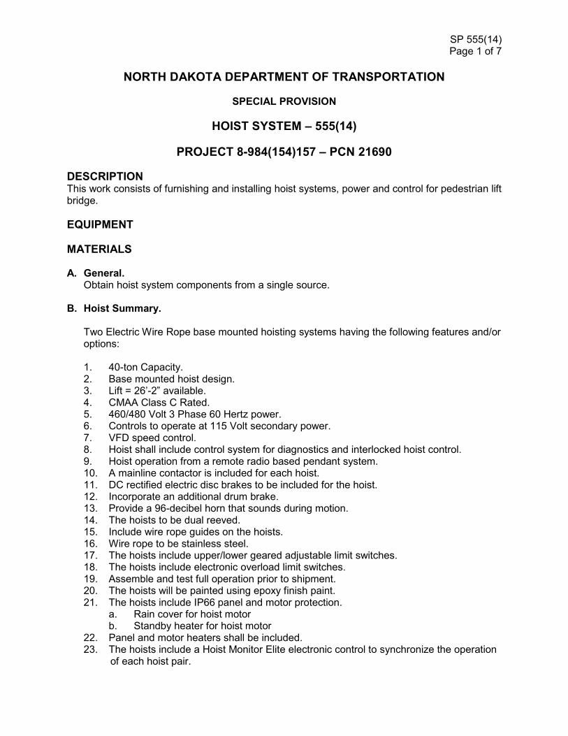
DESCRIPTION This work consists of furnishing and installing hoist systems, power and control for pedestrian lift bridge.
EQUIPMENT
MATERIALS A. General.
Obtain hoist system components from a single source.
B. Hoist Summary.
Two Electric Wire Rope base mounted hoisting systems having the following features and/or options: 1. 40-ton Capacity. 2. Base mounted hoist design. 3. Lift = 26’-2” available. 4. CMAA Class C Rated. 5. 460/480 Volt 3 Phase 60 Hertz power. 6. Controls to operate at 115 Volt secondary power. 7. VFD speed control. 8. Hoist shall include control system for diagnostics and interlocked hoist control. 9. Hoist operation from a remote radio based pendant system. 10. A mainline contactor is included for each hoist. 11. DC rectified electric disc brakes to be included for the hoist. 12. Incorporate an additional drum brake. 13. Provide a 96-decibel horn that sounds during motion. 14. The hoists to be dual reeved. 15. Include wire rope guides on the hoists. 16. Wire rope to be stainless steel. 17. The hoists include upper/lower geared adjustable limit switches. 18. The hoists include electronic overload limit switches. 19. Assemble and test full operation prior to shipment. 20. The hoists will be painted using epoxy finish paint. 21. The hoists include IP66 panel and motor protection.
a. Rain cover for hoist motor b. Standby heater for hoist motor
22. Panel and motor heaters shall be included. 23. The hoists include a Hoist Monitor Elite electronic control to synchronize the operation
of each hoist pair.

SP 555(14) Page 2 of 7
24. Synthetic lubricant is included for the hoist gearing. 25. Design hoists for outdoor – covered service operation. 26. Design hoists for low temperature (-4F) service. 27. Separate winch to raise/lower bridge support beam. 28. Provide safety lockout function for bridge support beam to ensure beam is in place
prior to lowering bridge at raised rest position.
WORK INCLUDES THE FOLLOWING:
1. Detailed design of completed hoist system, including hoists, cabling,
controls, and all appurtenances specified hereinafter. 2. Work drawings. 3. Fabrication of a complete hoist. 4. Inspection and shop testing. 5. Documentation and schedules.
1.01 REFERENCES
Equipment furnished under this section shall comply with the requirements of the
latest revision of the following standards:
OSHA – Occupational Safety and Health Administration
Part 1926.554 - Overhead Hoists
Part 1910.179 – Overhead and Gantry Cranes
CMAA – Crane Manufacturer’s Association of America
Specifications for Top Running Bridge & Gantry Type Multiple
Girder Electric Overhead Traveling Cranes - No. 70
Specifications for Top Running and Under Running Single Girder
Electric Overhead Cranes Utilizing Under Running Trolley Hoist -
No. 74
ANSI – American National Standards Institute
ASME – American Society of Mechanical Engineers
ANSI / ASME HST-4 - Performance Standard For Overhead
Electric Wire Rope Hoists
ANSI / ASME B30.16 – Overhead Hoists (Underhung)
ANSI / ASME B30.2 - Overhead and Gantry Cranes
SP 555(14) Page 3 of 7
(Top Running Bridge, Single Or Multiple Girder, Top Running
Trolley Hoist)
ANSI / ASME B30.11 – Monorails and Underhung Cranes
ANSI / ASME B30.17 – Cranes and Monorails (With Underhung
Trolley or Bridge) Safety Standard for Cableways, Cranes,
Derricks, Hoists, Hooks, Jacks and Slings
NEC - National Electric Code
Article 100, Article 240-1, Article 430-31, Article 430-51, Article 610-
1, Article 610-31
CONSTRUCTION REQUIREMENTS
A. General 1.03 SUBMITTALS
A. SHOP DRAWINGS AND EQUIPMENT DATA
1. Manufacturer’s catalog data for hoist. 2. Dimensional drawings and details for bridge hoist system. 3. Wiring schematics. – ship with hoist
B. OPERATIONS AND MAINTENANCE MANUALS (one set of Owner’s manuals in
paper and PDF version on Flash Drive) 1. Equipment function, normal operating characteristics, and limiting
conditions. 2. Assembly, installation, alignment, and maintenance instructions. 3. Lubrication and maintenance instructions. 4. Guide to “troubleshooting”. 5. Parts list. 6. As-built drawing. 7. Test results.
1.05 WARRANTIES
A. Provide one-year equipment warranty.
PART 2 - PRODUCTS
2.01 ACCEPTABLE PRODUCTS

SP 555(14) Page 4 of 7
A. Provide an electric wire rope type with hoist monitor and a remote radio based pendant control system or approved equal.
2.02 MATERIALS
Components Material
Bridge beams Steel, ASTM A36 or A992
End trucks Steel, ASTM A36
Trolley Steel, ASTM A36
Wheels Cast iron or steel
Hooks Forged steel
2.03 EQUIPMENT
A. HOIST
1. Equip hoist with an electro-mechanical load-limiting device that shall prevent lifting more than 110% of the rated load.
2. Hoist and trolley motors shall be per 1.01B above, as applicable. 3. Hoisting motor(s) shall be two-speed/two winding squirrel cage type with
a speed ratio of 6:1. 4. Hoisting motor(s) shall be totally enclosed with IP55 protection, minimum
class F insulation, Klixon type bimetal switch for thermal protection and shall have a 60% ED rating.
5. Rotary cam type limit switch equipped with 4 micro-switches shall be provided. Limit switch shall provide upper and lower limit of hoist travel, hoist slow down prior to reaching upper limit and phase sequence supervision at upper limit. An additional block operated limit shall be included.
6. Hoist motor brake shall be DC disc type with adequate torque to stop and hold over 125% of the hoist rated load.
7. Large diameter rope drum with a minimum of 36:1 drum to wire rope diameter ratio. Groove depth shall be at least 35% of rope diameter. The rope drum shall be equipped with a rope guide to help keep the rope aligned in the grooves of the drum.
8. Wire rope shall be constructed from galvanized steel having a minimum safety factor of 5.
9. Hoist reeving shall be double reeved. Lateral hook drift shall not exceed 1/8 inch per foot of vertical travel.
10. The hoist nameplate is to carry a CSA c/us rating. The actual hoist control enclosure rating shall be at least equivalent to IP55 / NEMA 4 type.
11. Hooks shall be made of forged alloy steel (34CrMo4QT or 34CrNiMo6QT) and shall be fitted with a spring-loaded flipper-type safety latch.
SP 555(14) Page 5 of 7
12. Hoist shall have a duty rating suitable for the load class and load cycles of the application.
13. AGMA quality class 12 machine cut, hardened and precision ground hoist gearing. The gears inside the hoist gearboxes on models up to 5 ton capacity shall be lubricated by semi-fluid grease. On models over 5 ton capacity the gears inside the hoist gearbox shall be lubricated with semi-fluid grease or oil.
14. Two each hoist control monitors – one per hoist 15. 350’ Profibus communication cable to connect both hoists. Synchronized
operations requires the hoist to be connected via this cable – CABLE CANNOT BE SPLICED.
B. WINCH 1. Supply a winch system to deploy the bridge support beam. 2. Provide a safety lockout function to detect bridge support beam is in the
fully deployed position prior to lowering bridge into raised rest position.
C. POWER SUPPLY 1. Power supply for the hoist shall be 460/480 volt, 3 ph., 60 Hz. All power
required for the operation of the hoist, trolley, and end trucks shall be developed from this source.
2. Runway electrification shall be 4-bar safety type rigid conductors as manufactured by Insul-8, Duct-O-Wire Company or Wampfler. Wall mounted disconnect switch and power to runway conductors shall be provided.
D. CONTROLS 1. Hoist control system shall provide the following features and/or options.
a. Hoist control system via a PLC for system lift speed and
synchronization between hoists to maintain a one inch level movement
b. Overload protection c. Run and fault supervision d. Starting and stopping at low speed e. Sudden loading supervision f. Single Radio control transmitter mounted and wired to PLC in Tower
control panel.
2. Pendant a. Eight-way operation, plug-in pushbutton pendant with radio control
shall be provided. b. Pendant shall include Start (momentary) button and Emergency Stop
(push to maintain, turn to release) that controls a mainline contactor in the bridge control panel.
SP 555(14) Page 6 of 7
c. Pushbutton shall be clearly marked with hoist travel directions. d. Up/Down push buttons to be momentary contact press to move type. e. Raise/Lower push buttons for bridge support beam winch control. f. Emergency stop push button to maintain, turn to release. g. Horn shall be press to sound type. h. Transmitter shall be outfitted with LCD display unit. i. Hoist shall be 2 speed magnetic reversing type. j. Electrical control enclosures shall be IP55 or NEMA 4 type.
Pushbutton enclosure shall have a rating of IP65, NEMA 4X, 4 or 5. A. LABELING
1. Hoist beam shall be labeled with load rating. 2. A corrosion-resistant nameplate shall be fixed to the bridge with the
following information: a. Name of manufacturer b. Mfg.’s model number and serial number c. Capacity d. Date of manufacture (month and year)
B. PAINTING
1. Hoist and trolley shall be factory painted (2-part epoxy) per manufacturer’s standards.
2. No paint on hoist wire rope.
PART 3 – EXECUTION
3.01 INSTALLATION AND INSPECTION
A. Inspect structure and hoist for conformance with reviewed shop drawings and contract documents prior to installation of equipment. Bring nonconforming work to the attention of the Owner prior to proceeding with hoist installation. Non-conforming bridge structure or installation must be corrected prior to load testing of hoist system. Costs of delays or additional work due to nonconforming bridge structure will be reimbursed by the Owner.
B. Bridge hoist shall be installed in conformance with manufacturer’s instructions and inspected by a manufacturer’s representative. Provide all necessary accessories to make bridge hoist complete, usable, and capable of meeting the operating requirements specified in the Operating Requirements. Test, adjust and clean equipment for acceptance by Owner.
C. The Contractor assumes all responsibility for operation and maintenance until the hoist has been accepted by Owner.
3.02 TESTING
SP 555(14) Page 7 of 7
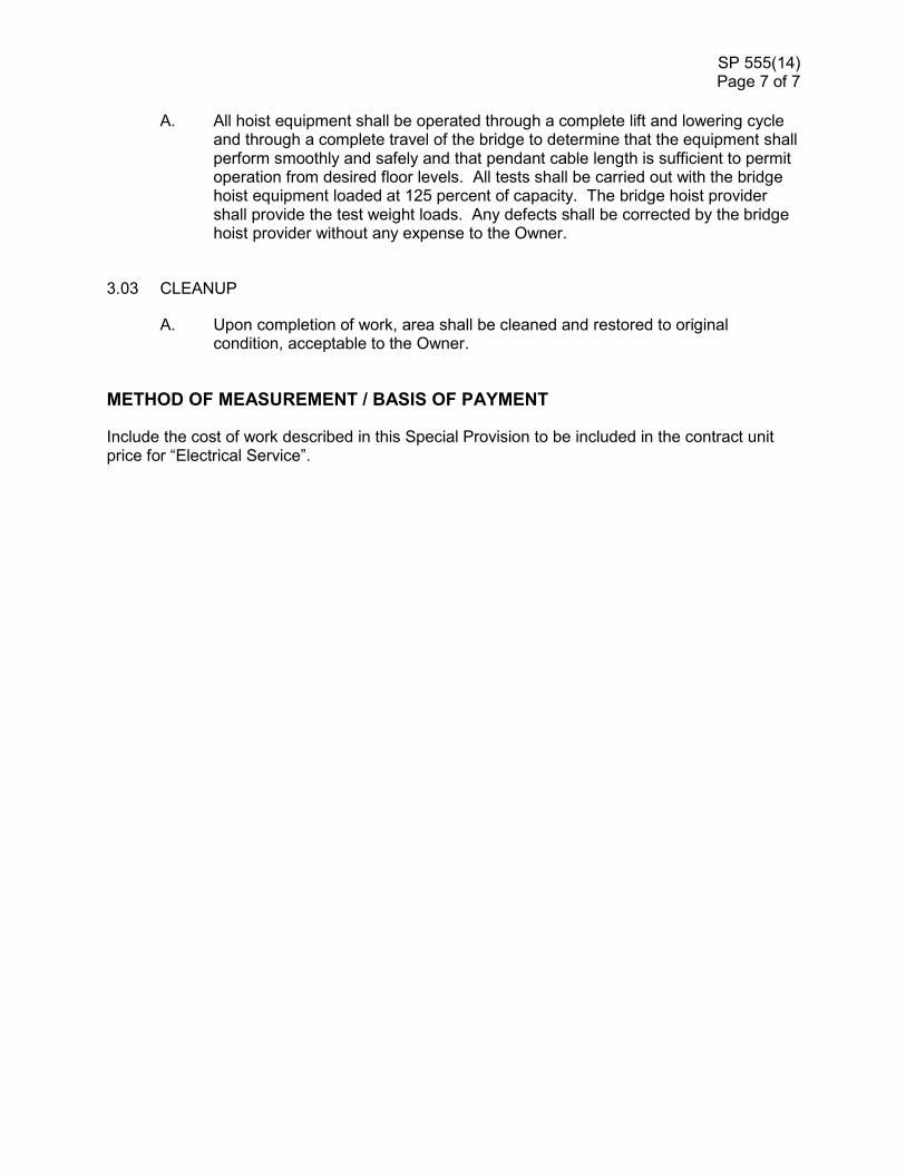
A. All hoist equipment shall be operated through a complete lift and lowering cycle and through a complete travel of the bridge to determine that the equipment shall perform smoothly and safely and that pendant cable length is sufficient to permit operation from desired floor levels. All tests shall be carried out with the bridge hoist equipment loaded at 125 percent of capacity. The bridge hoist provider shall provide the test weight loads. Any defects shall be corrected by the bridge hoist provider without any expense to the Owner.
3.03 CLEANUP
A. Upon completion of work, area shall be cleaned and restored to original condition, acceptable to the Owner.
METHOD OF MEASUREMENT / BASIS OF PAYMENT
Include the cost of work described in this Special Provision to be included in the contract unit price for “Electrical Service”.

SP 5182(14)
NORTH DAKOTA DEPARTMENT OF TRANSPORTATION
SPECIAL PROVISION
PERMITS AND ENVIRONMENTAL CONSIDERATIONS
PROJECT NUMBER: TAU-8-984(154)157 – PCN 21690
This Special Provision incorporates the Section 404, Sovereign Lands, Floodway
Review, City of Fargo Floodway Development, City of Moorhead Floodway
Development, City of Moorhead Conditional Use, Minnesota DNR Public Waters, and
Buffalo/Red River Watershed District Permits into the project. The Sovereign Lands
Permit is currently pending.
The Contractor shall be responsible for complying with all the terms and conditions as contained in the permit(s) attached hereto. Bidders shall become familiar with all standard conditions and special conditions of the permit(s) and submit their bid for the construction of this project based on the following:
• Section 404 Permit
The Section 404 Permit number NWO-2009-300-BIS authorizes fill within USACE jurisdictional waters. This 404 permit authorizes 0.00 acre of temporary and 0.03 acre of permanent jurisdictional wetland impacts. Temporary impacts were assumed by the designer and will be restored to preconstruction contours. See the Section 75 sheets of the design plans for the permitted impact areas. The Section 404 Permit is attached.
• Sovereign Lands Permit
This Sovereign Lands Permit Application has been submitted but has not yet been obtained. The permit is expected before bid and will be added to the project once received.
• Floodway Review Permit
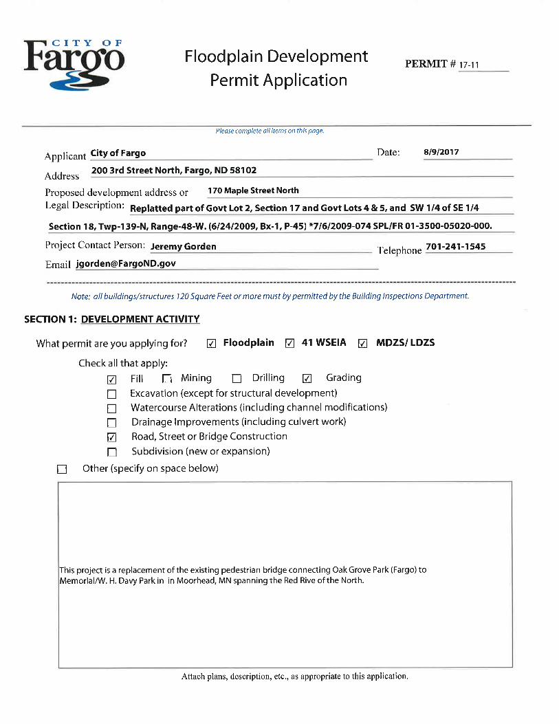
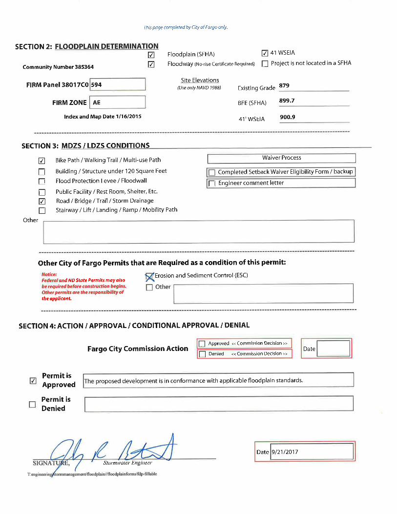
• City of Fargo Floodplain Development Permit
• City of Moorhead Floodplain Development Permit
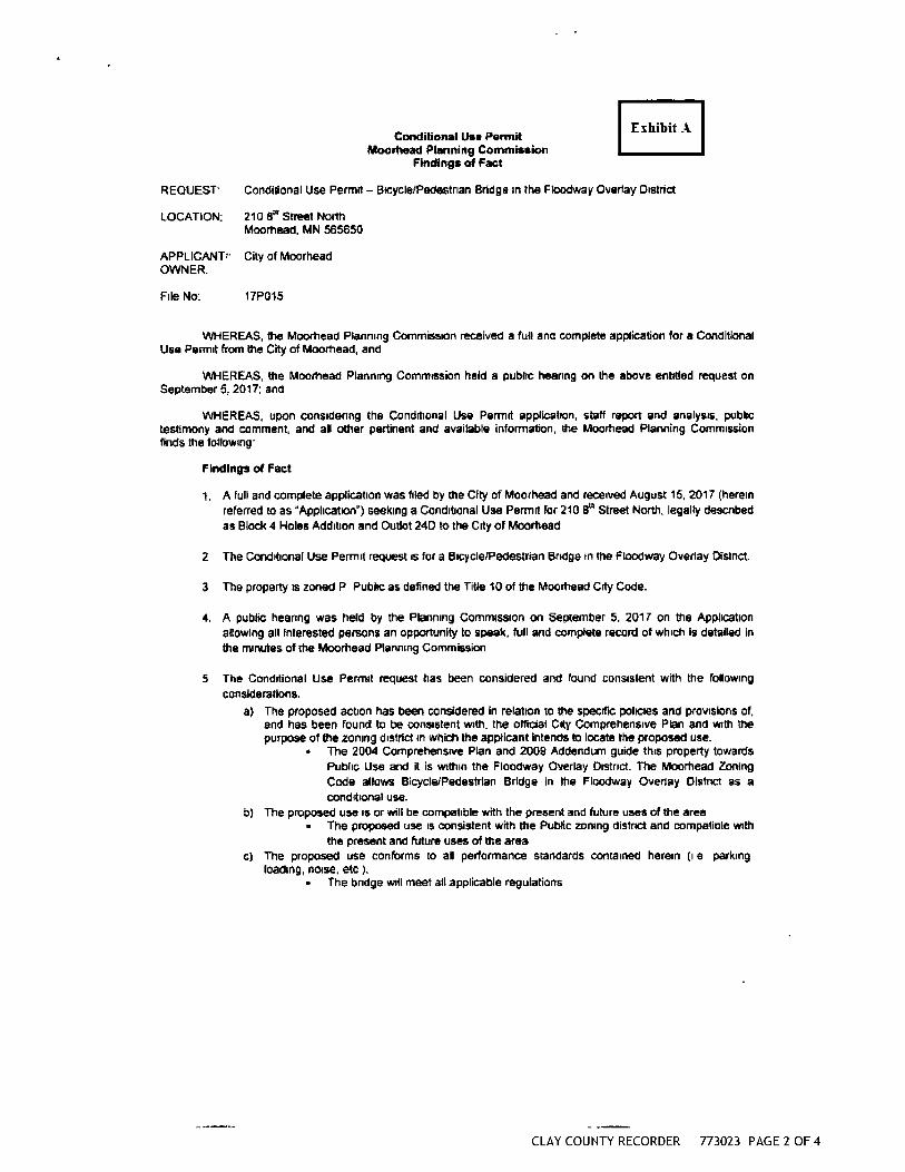
• City of Moorhead Conditional Use Permit

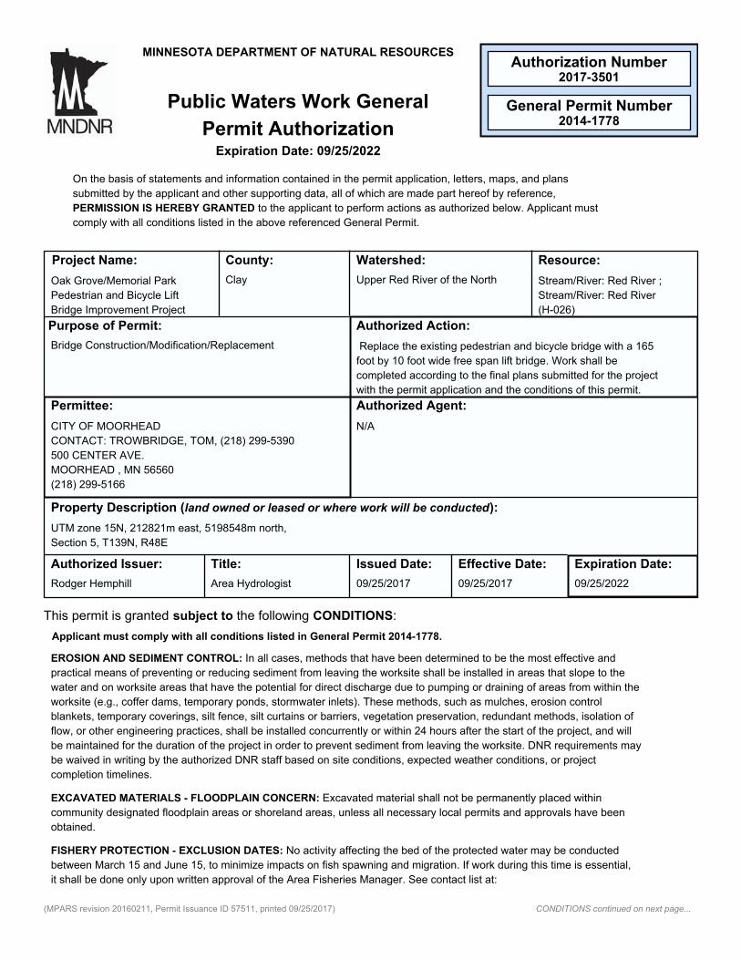
• Minnesota DNR Public Waters Permit
• Buffalo/Red River Watershed District Permit
The contractor shall be responsible for obtaining permits for impacts not authorized by the attached Permit obtained by the NDDOT.


State of North DakotaOffice of the State EngineerRegulatory Division900 EAST BOLJLEVÀRD AVE. . BISMARCK ND 5e505-0850Regulatory Division (701.) 32ß-2752 . FAX OOD 928-3696 . http://swc.nd.gov
September 7,2017
City of FargoAttn: Jody Bertrand200 3'd Street NorthFargo, ND 58102
Re: Oak Grove Park Pedestrian Lift Bridge - Floodway Review
Dear Mr. Bertrand,
On behalf of the State Engineer, and as directed in North Dakota Century Code $ 6l-16.2-14,theOff,rce of the State Engineer (OSE) staff has reviewed the proposed project located within themapped floodway of the Red River as requested by the City of Fargo. The proposed projectconsists of replacing the existing pedestrian bridge, which links Oak Grove Park in Fargo, NDand Memorial Park in Moorhead, MN.
The initial application submitted on August 11,2017, included a "no-rise" certificate and ahydraulic model comparing the existing and proposed conditions. The project includes theremoval of the existing bridge, construction of a new bridge, raising abutments and trailapproaches, enhancing design and safety features, and installing a mechanical lift system.
Upon review of the submitted material, the OSE staff found the project to cause no increase inthe water surface elevation of the 1-percent chance flood event. In addition, conveyance at theproject location was reviewed The OSE staff has determined this project appears to be incompliance with state and federal regulations as it pertains to floodplain management.
The City of Fargo is the regulatory authority and a permit is required for all development thattakes place within identified floodplains. If the City wishes to allow this project, please keep a
copy of the permit and associated documentation for proper record keeping. Any changes to thedesign must be submitted to the OSE for review and approval.
Sincerely,
Dunt'rl- Å,^fDionne Haynes, CFMState NFIP Coordinator
GARLAND ERBELE, P.E.SECRETARY AND STATE ENGINEER

AC: DHllT2I-}5
cc: Barb Denver, FEMA Region 8 (email)


Authorization Number
General Permit Number
2017-3501
2014-1778
MINNESOTA DEPARTMENT OF NATURAL RESOURCES
Public Waters Work General
Permit AuthorizationExpiration Date: 09/25/2022
On the basis of statements and information contained in the permit application, letters, maps, and plans
submitted by the applicant and other supporting data, all of which are made part hereof by reference,
PERMISSION IS HEREBY GRANTED to the applicant to perform actions as authorized below. Applicant must
comply with all conditions listed in the above referenced General Permit.
Resource:Watershed:County:Project Name:
Oak Grove/Memorial Park
Pedestrian and Bicycle Lift
Bridge Improvement Project
Clay Upper Red River of the North Stream/River: Red River ;
Stream/River: Red River
(H-026)
Authorized Action:Purpose of Permit:
Bridge Construction/Modification/Replacement Replace the existing pedestrian and bicycle bridge with a 165
foot by 10 foot wide free span lift bridge. Work shall be
completed according to the final plans submitted for the project
with the permit application and the conditions of this permit.
N/ACITY OF MOORHEAD
CONTACT: TROWBRIDGE, TOM, (218) 299-5390
500 CENTER AVE.
MOORHEAD , MN 56560
(218) 299-5166
Permittee: Authorized Agent:
Property Description (land owned or leased or where work will be conducted):
UTM zone 15N, 212821m east, 5198548m north,
Section 5, T139N, R48E
Area HydrologistRodger Hemphill
Expiration Date:Effective Date:Issued Date:Title:Authorized Issuer:
09/25/202209/25/201709/25/2017
This permit is granted subject to the following CONDITIONS:
Applicant must comply with all conditions listed in General Permit 2014-1778.
EROSION AND SEDIMENT CONTROL: In all cases, methods that have been determined to be the most effective and
practical means of preventing or reducing sediment from leaving the worksite shall be installed in areas that slope to the
water and on worksite areas that have the potential for direct discharge due to pumping or draining of areas from within the
worksite (e.g., coffer dams, temporary ponds, stormwater inlets). These methods, such as mulches, erosion control
blankets, temporary coverings, silt fence, silt curtains or barriers, vegetation preservation, redundant methods, isolation of
flow, or other engineering practices, shall be installed concurrently or within 24 hours after the start of the project, and will
be maintained for the duration of the project in order to prevent sediment from leaving the worksite. DNR requirements may
be waived in writing by the authorized DNR staff based on site conditions, expected weather conditions, or project
completion timelines.
EXCAVATED MATERIALS - FLOODPLAIN CONCERN: Excavated material shall not be permanently placed within
community designated floodplain areas or shoreland areas, unless all necessary local permits and approvals have been
obtained.
FISHERY PROTECTION - EXCLUSION DATES: No activity affecting the bed of the protected water may be conducted
between March 15 and June 15, to minimize impacts on fish spawning and migration. If work during this time is essential,
it shall be done only upon written approval of the Area Fisheries Manager. See contact list at:
CONDITIONS continued on next page...(MPARS revision 20160211, Permit Issuance ID 57511, printed 09/25/2017)

CONDITIONS (Continued from previous page)
http://files.dnr.state.mn.us/fisheries/management/dnr_fisheries_managers.pdf. Should work begin elsewhere in the project
area within these dates, all exposed soils that are within 200 feet of Public Waters and drain to those waters must
complete erosion control measures within 24 hours of its disturbance to prevent sediment from entering Public Waters.
EXCAVATED MATERIALS - RUNOFF CONCERN: Excavated materials must be deposited or stored in an upland area, in
a manner where the materials will not be redeposited into the public water by reasonably expected high water or runoff.
Departure from any previously approved spoil disposal plans may be allowed only through permit amendment.
MAINTENANCE - GENERAL PERMITS: Maintenance of work covered by this general permit may be performed upon
receipt of separate authorization or amended authorization under this permit.
BEST PRACTICES - MNDOT: Please refer to the manual “Best Practices for Meeting DNR General Public Waters Work
Permit GP 2004-0001” for guidance to meeting these and other conditions of this General Permit. A PDF version is
available at: http://www.dnr.state.mn.us/waters/watermgmt_section/pwpermits/gp_2004_0001_manual.html.
SMOOTH TRANSITION / MINIMUM ENCROACHMENT: At each end of the stabilized shoreline, the finished slope of the
riprap shall be varied in a fashion to produce a smooth transition with the natural shoreline. Also, riprap encroachment into
the water is to be limited to the minimum amount necessary and shall not create an obstruction to normal flows.
Erik Anthonisen, EWR District Manager
SRF Consulting Group, Inc., Agent
Wark, Jamie , Contact; SRF Consulting Group, Inc.
Phil Seefeldt, Conservation Officers, Moorhead
Steve Hofstad, BWSR Wetland Specialists, Clay
Jaime Thibodeaux, DNR Regional Environmental Assessment Ecologist, Region 1
Don Schultz, DNR Wildlife, Fergus Falls
Nathan Olson, DNR Fisheries, Detroit Lakes Area
Tim Magnusson, County, Clay
Bruce Albright, Watershed District, BUFFALO-RED RIVER WD
Evan Ingebrightson, Corps of Engineers, Clay
Kevin Kassenborg, SWCD, Clay SWCD
Lynn Foss, SWCD, Clay SWCD
cc:
Page 2 - Authorization Number 2017-3501

General Permit Number
2014-1778
MINNESOTA DEPARTMENT OF NATURAL RESOURCES
Amended
Public Waters Work General
PermitExpiration Date: 12/31/2018
Pursuant to Minnesota Statutes, Chapter 103G, and on the basis of statements and information contained in the
permit application, letters, maps, and plans submitted by the applicant and other supporting data, all of which are
made part hereof by reference, PERMISSION IS HEREBY GRANTED to the applicant to perform actions as
authorized below. This permit supersedes the original permit and all previous amendments.
Resource:Watershed:County:Project Name:
Region 1 Bridge & Culvert
General Permit
Becker, Beltrami,
Cass, Clay,
Clearwater, Douglas,
Grant, Hubbard,
Kittson, Lake of the
Woods, Mahnomen,
Marshall, Norman,
Otter Tail,
Pennington, Polk,
Pope, Red Lake,
Roseau, Stevens,
Traverse, Wadena,
Wilkin
All watersheds intersecting the
23-county DNR Northwest
Region
All public waters in the
23-county DNR Northwest
Region
Authorized Action:Purpose of Permit:
Bridge, culvert, and stormwater outfall repair and
replacement
Upon notice to and approval by authorized DNR personnel,
replacement or repair of bridges (open-bottom structures),
culverts (four-sided box, arch, or rounded pipe or barrel) and
stormwater outfalls is authorized. The work will be done
according to plans and specifications submitted with the
application and subject to all terms and conditions of this
permit. All work authorized by this permit must be designed by
a licensed professional engineer.
N/AGovernmental Agencies, Governmental Subdivisions
and General Public
Permittee: Authorized Agent:
Property Description (land owned or leased or where work will be conducted):
Various. The permittee must own, control, or have permission to access and use all lands on which the crossing or outfall
is located
Water Regulations Unit
Supervisor
Tom Hovey
Expiration Date:Effective Date:Issued Date:Title:Authorized Issuer:
12/31/201810/03/201410/03/2014
This permit is granted subject to the following CONDITIONS:
APPLICABLE FEDERAL, STATE, OR LOCAL REGULATIONS: The permittee is not released from any rules, regulations,
requirements, or standards of any applicable federal, state, or local agencies; including, but not limited to, the U.S. Army
Corps of Engineers, Board of Water and Soil Resources, MN Pollution Control Agency, watershed districts, water
management organizations, county, city and township zoning.
NOT ASSIGNABLE: This permit is not assignable by the permittee except with the written consent of the Commissioner
Page 3 - Authorization Number 2017-3501 - General Permit Number 2014-1778 (ID 13481)

GENERAL PERMIT CONDITIONS (Continued from previous page)
of Natural Resources.
NO CHANGES: The permittee shall make no changes, without written permission or amendment previously obtained from
the Commissioner of Natural Resources, in the dimensions, capacity or location of any items of work authorized
hereunder.
SITE ACCESS: The permittee shall grant access to the site at all reasonable times during and after construction to
authorized representatives of the Commissioner of Natural Resources for inspection of the work authorized hereunder.
TERMINATION: This permit may be terminated by the Commissioner of Natural Resources at any time deemed
necessary for the conservation of water resources of the state, or in the interest of public health and welfare, or for violation
of any of the conditions or applicable laws, unless otherwise provided in the permit.
COMPLETION DATE: Construction work authorized under this permit shall be completed on or before the date specified
above. The permittee may request an extension of the time to complete the project by submitting a written request,
stating the reason thereof, to the Commissioner of Natural Resources.
WRITTEN CONSENT: In all cases where the permittee by performing the work authorized by this permit shall involve the
taking, using, or damaging of any property rights or interests of any other person or persons, or of any publicly owned
lands or improvements thereon or interests therein, the permittee, before proceeding, shall obtain the written consent of all
persons, agencies, or authorities concerned, and shall acquire all property, rights, and interests needed for the work.
PERMISSIVE ONLY / NO LIABILITY: This permit is permissive only. No liability shall be imposed by the State of
Minnesota or any of its officers, agents or employees, officially or personally, on account of the granting hereof or on
account of any damage to any person or property resulting from any act or omission of the permittee or any of its agents,
employees, or contractors. This permit shall not be construed as estopping or limiting any legal claims or right of action of
any person other than the state against the permittee, its agents, employees, or contractors, for any damage or injury
resulting from any such act or omission, or as estopping or limiting any legal claim or right of action of the state against
the permittee, its agents, employees, or contractors for violation of or failure to comply with the permit or applicable
conditions.
EXTENSION OF PUBLIC WATERS: Any extension of the surface of public waters from work authorized by this permit
shall become public waters and left open and unobstructed for use by the public.
GP AUTHORIZATION - APPLY USING MPARS: The permittee shall apply for prior authorization for all projects to be
constructed under this General Permit using the MNDNR Permitting and Reporting System (MPARS) at
www.mndnr.gov/mpars/signin . Users will need to create an account the first time they access the system. Once created,
click on the link for ‘Apply for a New Permit/Authorization’ under the Actions box and complete the application questions.
CONTRACTOR RESPONSIBILITY: The permittee shall ensure the contractor has received and thoroughly understands all
conditions of this permit. Contractors must obtain a signed statement from the property owner stating that permits
required for work have been obtained or that a permit is not required, and mail a copy of the statement to the regional DNR
Enforcement office where the proposed work is located. The Landowner Statement and Contractor Responsibility Form
can be found at: http://www.bwsr.state.mn.us/wetlands/wca/index.html#general.
INVASIVE SPECIES - EQUIPMENT DECONTAMINATION: All equipment intended for use at a project site must be free
of prohibited invasive species and aquatic plants prior to being transported into or within the state and placed into state
waters. All equipment used in designated infested waters, shall be inspected by the Permittee or their authorized agent
and adequately decontaminated prior to being transported from the worksite. The DNR is available to train inspectors
and/or assist in these inspections. For more information refer to the "Best Practices for Preventing the Spread of Aquatic
Invasive Species" at http://files.dnr.state.mn.us/publications/ewr/invasives/ais/best_practices_for_prevention_ais.pdf.
Contact your regional Invasive Species Specialist for assistance at www.mndnr.gov/invasives/contacts.html. A list of
designated infested waters is available at www.mndnr.gov/invasives/ais/infested.html. A list of prohibited invasive species
is available at www.mndnr.gov/eco/invasives/laws.html#prohibited.
MAINTENANCE: Maintenance of this project to originally authorized conditions may be authorized by amendment to this
permit.
APPLICABLE PROJECTS: This permit applies only to the replacement, reconstruction and repair (including associated
minor channel or shoreline work) of existing bridges, culverts and outfalls, including that necessary to restore channel
dimensions to the original or as-constructed cross-section near the project site. To qualify under this general permit,
unless specifically waived by authorized DNR personnel, all projects affecting Public Waters must be designed under the
Page 4 - Authorization Number 2017-3501 - General Permit Number 2014-1778 (ID 13481)

GENERAL PERMIT CONDITIONS (Continued from previous page)
supervision of a registered professional engineer. Any project not meeting applicable conditions of this permit or a project
the DNR identifies as having the potential for significant resource impacts, is not authorized herein. Rather, such projects
will require an individual permit application.
PRELIMINARY ENGINEERING : This permit authorizes preliminary engineering studies associated with bridge planning
(e.g. core sampling). All core holes must be sealed in accordance with Department of Health well sealing requirements.
On infested waters, all equipment in contact with the water must be decontaminated as required by condition per the
Invasive Species condition.
DNR NOTIFICATION: The permittee shall notify the Area Hydrologist at least five days in advance of the commencement
of the work. An email notification of the pre-construction meeting will suffice for this notification.
RIGHT TO REVIEW: The DNR reserves the right to review this permit as additional hydrologic and other data become
available and order changes to the authorization as may become necessary to protect public interest. Additional modeling
may also be required for temporary fill or temporary structures required during demolition or construction
HYDROLOGIC/HYDRAULIC DATA REPORTING: Unless waived by the DNR Area Hydrologist, hydrologic modeling to
show the impacts of the structure(s) on the 100-year flood elevation and calculated velocities through the structures for
both 2-year and 10-year peak flows are required.
FLOOD STAGE/DAMAGES NOT INCREASED : For replacements of existing crossings, if the existing crossing has a
swellhead of one-half of one foot or less for the regional flood, then replacement crossing shall comply with the provisions
for new crossings in (A) below. If the existing crossing has a swellhead of more than one-half of one foot for the regional
flood, stage increased up to the existing swellhead may be allowed if field investigation and other available data indicate
that no significant flood damage potential exists upstream from the crossing based on analysis of data submitted by the
applicant. The swellhead for the replacement crossing may exceed the existing swellhead if it complies with the provisions
found in (A) below. A. No approach fill for a crossing shall encroach upon an approved community designated floodway.
When a floodway has not been designated or when a floodplain management ordinance has not been adopted and
approved, increases in flood stage in the regional flood of up to one-half of one foot shall be approved if they will not
materially increase flood damage potential. Additional increase may be permitted if: a field investigation and other available
data indicate that no significant increase in flood damage potential would occur upstream or downstream, and any
increases in flood stage are reflected in the floodplain boundaries and flood protection elevation adopted in the local
floodplain management ordinance;
ENVIRONMENTAL REVIEW: If the bridge, culvert, or stormwater outfall work is part of a road project that requires
mandatory environmental review pursuant to MN Environmental Quality Board rules, then this permit is not valid until
environmental review is completed. The outcome of the environmental review may affect work authorized by this permit
STATE AND FEDERAL LISTED SPECIES PROHIBITION: If there are unresolved concerns regarding impacts to federally
or state listed species (endangered, threatened, or special concern), this general permit is not applicable, and the project
must be submitted as an individual permit application. Compliance with DNR and federal guidelines established for a listed
species (e.g. Topeka Shiner conditions) would constitute a resolved concern.
RARE NATIVE PLANT COMMUNITIES AND SITES OF HIGH AND OUTSTANDING BIODIVERSITY SIGNIFICANCE: If
DNR Ecological and Water Resources staff determines that Rare Native Plant Communities or Sites of High or
Outstanding Biodiversity Significance are present, precautions must be implemented to minimize disturbance and impacts
to these areas. Actions to minimize disturbance in this area may include, but are not limited to the following: (1) As much
as possible, operate within already-disturbed areas; (2) Minimize vehicular disturbance in the area (allow only vehicles
necessary for installation); (3) Do not park equipment or stockpile supplies in the area; (4) If possible, do work in autumn
or winter, to avoid damaging plants during the growing season; (5) Reduce runoff by completing the work as rapidly as
possible and using erosion control measures such as straw bales or silt fencing; (6) Revegetate disturbed soil with native
species suitable to the local habitat as soon after construction as possible; (7) Use only invasive-free mulches, topsoils,
and seed mixes.
FISH PASSAGE, SEDIMENT TRANSPORT AND GRADE CONTROL: Bridges, culverts and other crossings shall provide
for fish movement unless the structure is intended to impede rough fish movement, aquatic invasive species movement, or
the stream has negligible fisheries value as determined by the Area Hydrologist in consultation with the Area Fisheries
Manager. The accepted practices for achieving these conditions include: A. Where possible a single culvert or bridge shall
span the natural bankfull width adequate to allow for debris and sediment transport rates to closely resemble those of
upstream and downstream conditions. A single culvert shall be recessed in order to pass bedload and sediment load.
Additional culvert inverts should be set at a higher elevation. All culverts should match the alignment and slope of the
Page 5 - Authorization Number 2017-3501 - General Permit Number 2014-1778 (ID 13481)

GENERAL PERMIT CONDITIONS (Continued from previous page)
natural stream channel, and extend through the toe of the road side slope. “Where possible” means that other conditions
may exist and could take precedence, such as unsuitable substrate, natural slope and background velocities, bedrock,
flood control, 100-yr (1% chance) flood elevations, wetland/lake level control elevations, local ditch elevations, and other
adjacent features. B. Rock Rapids or other structures may be used to retrofit crossings to mimic natural conditions.
Please contact your area hydrologist for the most recent design information and other resources on achieving fish
passage, sediment transfer, and grade control.
TERRESTRIAL SPECIES MOVEMENT : Structures will not be detrimental to significant wildlife habitat. In some cases
the DNR may require crossings be designed for species movement. If the crossing is located at a significant wildlife travel
corridor as determined by DNR Wildlife or Ecological and Water Resources staff, the crossing will be designed to
minimize concerns. Generally, bridges are preferred over culverts if there is adequate clearance beneath road decks and
adequate dry ground at normal flow conditions. Design information may be found at
http://files.dnr.state.mn.us/waters/watermgmt_section/pwpermits/gp_2004_0001_chapter1.pdf.
FLOWLINE/GRADIENT NOT CHANGED : Replacement of culverts or crossings are to follow (or be restored to) the
natural alignment and profile of the stream. Changes from the existing flowline, gradient or alignment must be consistent
with the Water Level Control and Fish Passage conditions and authorized by the DNR Area Hydrologist.
NAVIGATION MAINTAINED/IMPROVED : The structures final design will not obstruct reasonable public navigation as
determined by the DNR. For bridges 3 feet above the calculated 50-year flood stage ordinarily satisfies navigational
clearance requirements. For culverts 3 feet above the ordinary high water level (top of the bank for streams/rivers) ordinarily
satisfies navigation requirements.
WATER LEVEL CONTROL : Permittee is responsible for maintaining existing water level control elevations.
TEMPORARY IMPACTS DURING CONSTRUCTION: Construction methods not finalized at the time of project review
shall be submitted for review and approval at a later date. Temporary work below the Ordinary High Water (OHW)
elevation, such as channel diversions, placement of temporary fill, structures for work pads/dock walls, bypass roads,
coffer dams, or staging areas to aid in the demolition or construction of any authorized structure shall be submitted for
review and approval in writing by the DNR Area Hydrologist prior to beginning work. This is normal procedure for bridge or
culvert projects as we recognize that final project designs are often posted for bid without final construction/demolition
plans. The following conditions must be met:
A: AQUATIC INVASIVE SPECIES - EQUIPMENT DECONTAMINATION: All equipment intended for use at a project site
must be free of prohibited invasive species and aquatic plants prior to being transported into or within the state and placed
into state waters. All equipment used in designated infested waters, shall be inspected by the Permittee or their
authorized agent and adequately decontaminated prior to being transported from the worksite. The DNR is available to
train inspectors and/or assist in these inspections. For more information refer to the "Best Practices for Preventing the
Spread of Aquatic Invasive Species" at
http://files.dnr.state.mn.us/publications/ewr/invasives/ais/best_practices_for_prevention_ais.pdf. Contact your regional
Invasive Species Specialist for assistance at www.mndnr.gov/invasives/contacts.html. A list of designated infested waters
is available at http://files.dnr.state.mn.us/eco/invasives/infested_waters.pdf. A list of prohibited invasive species is
available at www.mndnr.gov/eco/invasives/laws.html#prohibited
B: WORK EXCLUSION DATES FOR FISH SPAWNING AND MOVEMENT: Work within Public Waters may be restricted
due to fish spawning,migration concerns, or the protection of fish habitat. Dates of fish spawning and migration vary by
species and location throughout the state. Specific dates for each DNR Region may be found on page 3 of Chapter 1 of
the manual: Best Practices for Meeting DNR General Waters Work Permit GP2004-0001.
http://www.dnr.state.mn.us/waters/watermgmt_section/pwpermits/gp_2004_0001_manual.html. Work in the water is not
allowed within these dates. The DNR Area Hydrologist shall be contacted about waiving work exclusion dates where work
is essential and/or where permittee demonstrates that a project will minimize impacts to fish habitat, spawning, and
migration. All waivers require approval of the Area Fisheries Supervisor.
C: HYDROLOGIC MODELING: Hydrologic modeling of temporary fill or temporary structures may be required by DNR
Area Hydrologist in order to evaluate impacts to the 100-yr (1% chance) flood elevation. Contingency plans may also be
required to ensure all construction equipment and unsecured construction materials are moved out of the floodplain to
prevent impacts to the 100-yr (1% chance) flood elevation or from being swept away by flood waters.
D: TEMPORARY FILL: If approved, temporary fill shall be free of organic material or any material that may cause siltation
or pollute the waterbody. All such material shall be removed and the area restored to pre-existing profiles prior to project
completion.
Page 6 - Authorization Number 2017-3501 - General Permit Number 2014-1778 (ID 13481)
GENERAL PERMIT CONDITIONS (Continued from previous page)
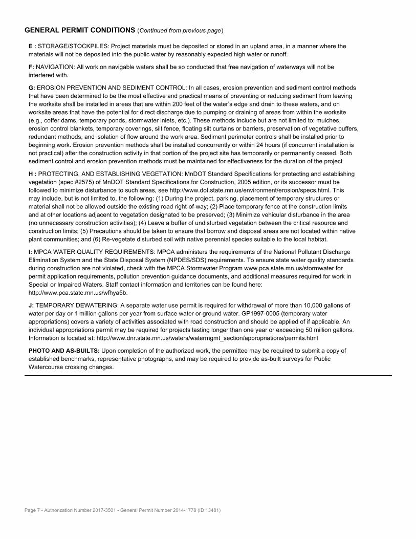
E : STORAGE/STOCKPILES: Project materials must be deposited or stored in an upland area, in a manner where the
materials will not be deposited into the public water by reasonably expected high water or runoff.
F: NAVIGATION: All work on navigable waters shall be so conducted that free navigation of waterways will not be
interfered with.
G: EROSION PREVENTION AND SEDIMENT CONTROL: In all cases, erosion prevention and sediment control methods
that have been determined to be the most effective and practical means of preventing or reducing sediment from leaving
the worksite shall be installed in areas that are within 200 feet of the water’s edge and drain to these waters, and on
worksite areas that have the potential for direct discharge due to pumping or draining of areas from within the worksite
(e.g., coffer dams, temporary ponds, stormwater inlets, etc.). These methods include but are not limited to: mulches,
erosion control blankets, temporary coverings, silt fence, floating silt curtains or barriers, preservation of vegetative buffers,
redundant methods, and isolation of flow around the work area. Sediment perimeter controls shall be installed prior to
beginning work. Erosion prevention methods shall be installed concurrently or within 24 hours (if concurrent installation is
not practical) after the construction activity in that portion of the project site has temporarily or permanently ceased. Both
sediment control and erosion prevention methods must be maintained for effectiveness for the duration of the project
H : PROTECTING, AND ESTABLISHING VEGETATION: MnDOT Standard Specifications for protecting and establishing
vegetation (spec #2575) of MnDOT Standard Specifications for Construction, 2005 edition, or its successor must be
followed to minimize disturbance to such areas, see http://www.dot.state.mn.us/environment/erosion/specs.html. This
may include, but is not limited to, the following: (1) During the project, parking, placement of temporary structures or
material shall not be allowed outside the existing road right-of-way; (2) Place temporary fence at the construction limits
and at other locations adjacent to vegetation designated to be preserved; (3) Minimize vehicular disturbance in the area
(no unnecessary construction activities); (4) Leave a buffer of undisturbed vegetation between the critical resource and
construction limits; (5) Precautions should be taken to ensure that borrow and disposal areas are not located within native
plant communities; and (6) Re-vegetate disturbed soil with native perennial species suitable to the local habitat.
I: MPCA WATER QUALITY REQUIREMENTS: MPCA administers the requirements of the National Pollutant Discharge
Elimination System and the State Disposal System (NPDES/SDS) requirements. To ensure state water quality standards
during construction are not violated, check with the MPCA Stormwater Program www.pca.state.mn.us/stormwater for
permit application requirements, pollution prevention guidance documents, and additional measures required for work in
Special or Impaired Waters. Staff contact information and territories can be found here:
http://www.pca.state.mn.us/wfhya5b.
J: TEMPORARY DEWATERING: A separate water use permit is required for withdrawal of more than 10,000 gallons of
water per day or 1 million gallons per year from surface water or ground water. GP1997-0005 (temporary water
appropriations) covers a variety of activities associated with road construction and should be applied of if applicable. An
individual appropriations permit may be required for projects lasting longer than one year or exceeding 50 million gallons.
Information is located at: http://www.dnr.state.mn.us/waters/watermgmt_section/appropriations/permits.html
PHOTO AND AS-BUILTS: Upon completion of the authorized work, the permittee may be required to submit a copy of
established benchmarks, representative photographs, and may be required to provide as-built surveys for Public
Watercourse crossing changes.
Page 7 - Authorization Number 2017-3501 - General Permit Number 2014-1778 (ID 13481)

Permit # 17-077 Status Report: Approved
Applicant Information
Name Organization Address Email Phone Number(s)
Jeremy Gorden City of Fargo200 3rd Street North
Fargo, ND [email protected]
tel:701-241-1545
mobile: 701-241-1545
fax:
General Information
(1) The proposed project is a:
Bridge Installation / Removal / Modification
(2) Legal Description
(3) County: Clay Township: Moorhead Range: 48 Section: 5 1/4: All of Blocks 4, 68 and 70 and part of 7th St, Holels Addn; Part of outlots 22C, 22D, 24D; all of 23E
and 24D, Section 5, T139N R48W
(4) Describe in detail the work to be performed. The proposed improvement to the bridge is partially based on the recommendations of the Lifespan and
Replacement Study of the Fargo-Moorhead Bicycle/Pedestrian Bridges, completed in June 2006. The proposed improvement includes construction of a new
bridge, new bridge abutments with pile foundations, enhanced bridge and approach lighting, and installation of a mechanical lift at the Oak Grove/Memorial
park pedestrian and bicycle bridge over the Red River at its existing location.
(5) Why is this work necessary? Explain water related issue/problem being solved. The proposed pedestrian and bicycle bridge improvement is needed to increase
the number of days the bridge is accessible, to improve the safety and reliability of the structure, enhance walkability in the urban core, and to protect the
investment that the cities of Fargo and Moorhead have already made in the bike trail system. The improvement will provide a reliable option for people
choosing to walk or bike for their daily commute, while enhancing recreational opportunities along the scenic river corridor and ensuring that the river
amenity is accessible as often as possible.
Status
Status Notes Date
Approved None Aug. 14, 2017
Application
CompleteNone Aug. 14, 2017
Received None Aug. 14, 2017
Conditions
NOTE: This permit does not relieve the applicant of any requirements for other permits which may be necessary from Township, County, State, or Federal Government
Agencies.

STATE PROJECT NO.SECTION
NO.SHEET
NO.
11/8/2017 11:37:04 AM elaidley
ND 2
TAU-8-984(154)157
Revised 11/8/2017
TABLE OF CONTENTS 1
.. .. ...
Section Page(s) Description
PLAN SECTIONS
1 Title Sheet1
2 Table of Contents1
4 Scope of Work1
6 Notes1 - 2
6 Lighting Notes3
6 Environmental Notes4
8 Quantities1
11 Earthwork & Topsoil Summary1
20 Temporary Erosion Control - Flotation Silt Curtain1
20 Sidewalk Pavement Joint & Reinforcement Details2
20 Pedestrian Fence Details3
20 Riprap Key Detail4
20 Landscaping Appurtenances5
30 Proposed Typical Sections1
40 Removals1
60 Plan & Profile1 - 3
75 Wetland Impacts1 - 2
76 Temporary Erosion Control1
77 Permanent Erosion Control1
82 Survey Data Layouts1 - 2
100 Traffic Control Devices List1
100 Work Zone Traffic Control2
140 Lighting1 - 5
170 Bridge1 - 13
200 Cross Sections1 - 9
Number Description
LIST OF STANDARD DRAWINGS
NDDOT AbbreviationsD-101-1, 2, 3
NDDOT Utility Company and Organization AbbreviationsD-101-10
Line StylesD-101-20, 21
SymbolsD-101-30, 31, 32
Erosion Control - Fiber Roll Placement DetailsD-261-1
Longitudinal Joint DetailsD-550-2
Transverse Contraction Joint DetailsD-550-3
Transverse Expansion Joint DetailD-550-4
Transverse Construction JointD-550-5
Pile Splice DetailsD-622-1
Breakaway Systems For Construction Zone Signs - Perforated TubeD-704-7
Breakaway Systems For Construction Zone Signs - U-Channel PostD-704-8
Construction Sign Details - Terminal And Guide SignsD-704-9
Construction Sign Details - Regulatory SignsD-704-10
Barricade And Channelizing Device DetailsD-704-13
Construction Sign Punching And Mounting DetailsD-704-14
Portable Sign Support AssemblyD-704-50
SidewalkD-750-2
Chain Link FenceD-752-2
Concrete Foundations (Traffic Signals & Highway Lighting)D-770-1
Feed Points (Roadway Lighting)D-770-2
Pull Box DetailsD-770-3
Lighting And Signal DetailsD-770-4
Bridge Bench MarksD-900-1
Number Description
SPECIAL PROVISIONS
SP 003(14) Temporary Erosion and Sediment Best Management Practices
SP 004(14) Federal Migratory Bird Treaty Act
SP 5182(14) Permits and Environmental Considerations
SP 553(14) Architectural Finish and Stain
SP 555(14) Hoist System

1
2
3
4
5
6
50
51
52
Legend
Sheet Pile Retaining Wall
Sta 51+63.14 (PR8TH)
End 8th Street Reconstruction
Sta 1+09.65 (PRBRIDGE)
Begin Shared Use Path Reconstruction
Begin Project TAU-8-984(154)157
Sta 6+07.75 (PRBRIDGE)
End Shared Use Path Reconstruction
End Project TAU-8-984(154)157
Sta 50+05.14 (PR8TH)
Begin 8th Street Reconstruction
Sta 3+91.72 (PRBRIDGE)
Begin Sheet Pile Retaining Wall
Sta 4+27.00 (PRBRIDGE)
End Sheet Pile Retaining Wall
Sidewalk Concrete 4IN
Sta 2+20.49 (PRBRIDGE)
Begin Pedestrian Bridge
Red River
Riprap Grade II
Fargo, ND
Oak Grove Park
Moorhead, MN
Memorial Park
Sta 3+88.99 (PRBRIDGE)
End Pedestrian Bridge
(See Section 6 & 20)
10' Spacing OC
Landscaping Appurtenances
10608
11/08/17
TAU-8-984(154)157 4 1
Scope of Work
Oak Grove/Memorial Park Pedestrian Lift Bridge
Fargo, ND
Moorhead, MN
Eric Laidley,
STATE PROJECT NO.
ND
NO.
SHEET
NO.
SECTION
11/8/2017 elaidley I:\Projects\09000\9428\8984154.157\Design\Addendum 1\Plan\004SW_001_Scope_AD-A.dgn12:28:42 PM
City of Fargo
document is stored at the
on and the original
PE- ,
Registration Number
issued and sealed by
This document was originally
Revised 11/08/17

Revised 11/08/17
NOTES
11/8/2017 12:29:39 PM I:\Projects\09000\9428\8984154.157\Design\Addendum 1\Plan\006NT_001_notes_AD-A.docm
STATE PROJECT NO. SECTION
NO. SHEET
NO.
ND TAU-8-984(154)157 6 1
This document was originally
issued and sealed by
Eric Laidley,
Registration Number
PE-10608,
on 11/08/17 and the original
document is stored at the
City of Fargo
100-P01 NOISE RESTRICTION: Noise levels will be minimized by ensuring that construction equipment is equipped with a recommended muffler in good
working order and by ensuring that construction activities with elevated noise levels are limited to between the hours of 7:00 a.m. and 7:00 p.m.
202-P01 REMOVAL OF BITUMINOUS SURFACING: The square yardage of “Removal of
Bituminous Surfacing” includes the entire asphalt surfacing within the project
work area and the entire aggregate base except the bottom two inches. The quantity of Removal of Bituminous Surfacing has been deducted from the
excavation quantity. This work shall consist of removing the existing surfacing and any aggregate base encountered.
203-010 SHRINKAGE: 25 percent additional volume is included for shrinkage in earth embankment.
203-385 AVERAGE HAUL: No average haul has been computed for this project.
216-P01 WATER: Include costs for water required for dust control and compaction efforts in other bid items.
302-P01 AGGREGATE BASE COURSE CL 5: Measure aggregate base course as in-place
compacted volume (CY). The measured volume will not be adjusted for compaction shrinkage.
622-P01 PILE DRIVING: Do not drive piling between the hours of 7:00 p.m. and 7:00
a.m.
624-P01 PEDESTRIAN FENCE: Furnish and install removable 3’-6” pedestrian fence to the
retaining walls as described in the plans. Include all costs in “Pedestrian Fence”.
708-P01 SEEDING CLASS III: Use Class III seed as follows:
Species Pound Pure Live
Seed/Acre
Kentucky Bluegrass 132
Creeping Red Fescue 22
Fine Leaf Perennial Ryegrass 66
220
Apply seeding at a rate of 220 lb/acre. Use starter fertilizer with a mixture of 12-24-12 at an application rate of 220 pounds per acre. After eight weeks or
when the grass has been evenly established to a height of 2”, whichever occurs first, apply turf fertilizer at a rate of 110 pounds per acre, conforming to a
mixture of 24-24-4. Include all costs, including fertilizing, in “Seeding Class III”.
750-P01 SIDEWALK CONCRETE 4IN: Construct contraction joints every 5.0’ on the 10’ wide shared use paths. Construct contraction joints every 9.0’ on the 18’ wide
8th street pavement. Place one-half-inch expansion joints at bituminous tie in locations. Seal all expansion joints with polymeric joint sealant. All
sidewalks/paths will have a No. 3 deformed reinforcing bar placed 24” o.c. both ways. The bar will be six (6) inches shorter than the width of the slab and placed accurately at one-half the depth of the slab. Plastic chairs will be used.
Saw all longitudinal and transverse joints. Saw a centerline longitudinal joint on the paths. Saw joints in a timely manner to prevent any uncontrolled random
cracking. If random cracking occurs, the Contractor will be required to remove and replace all damaged panels at no cost. Include all costs in “Sidewalk Concrete 4IN”.
750-P02 PIGMENTED IMPRINTED CONCRETE: Develop a mix design using any size coarse
aggregate specified in Section 802.01 C.2, “Coarse Aggregate”. Provide a pigment from the list below or provide an approved equal. To be
considered an approved equal, pigments must meet the requirements of ASTM C 979.
1. Number 366 Natural Red, produced by Soloman Colors, Inc.
http://www.solomoncolors.com/; 2. Brick Red Pigment Number 160, produced by Davis Colors
http://www.daviscolors.com/; or
3. Pigment R/M – Brick Red, produced by Southern Color Company http://www.southerncolor.com/.
Use the same supplier for all colored concrete placed under the contract.
Add pigment at the ratio recommended by the manufacturer directly into the mixer along with the aggregate, cement, and water. Add pigment while the
mixer is operating at mixing speed. Continue mixing for 5 to 10 minutes or between 50 and 100 revolutions.
Form a pattern in the concrete using a roller to create a 4 inch x 8 inch brick pattern.
Cure concrete using curing compound that meets the requirements of ASTM C 309, Type 1.
Include all costs plus the cost of reinforcement shown in the plans in “Pigmented Imprinted Concrete.
772-P01 PADLOCKS: Contact Joe Moore to obtain padlocks for feed
points from the city of Moorhead, MN.
Joe Moore Electric Operations Manager
Moorhead Public Service 500 Center Avenue, PO Box 779 Moorhead, MN 56561
Office: 218-477-8083
Revised 11/08/17
NOTES
11/8/2017 12:29:39 PM I:\Projects\09000\9428\8984154.157\Design\Addendum 1\Plan\006NT_001_notes_AD-A.docm
STATE PROJECT NO. SECTION
NO. SHEET
NO.
ND TAU-8-984(154)157 6 2
This document was originally
issued and sealed by
Eric Laidley,
Registration Number
PE-10608,
on 11/08/17 and the original
document is stored at the
City of Fargo
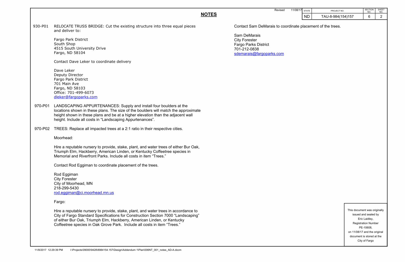
930-P01 RELOCATE TRUSS BRIDGE: Cut the existing structure into three equal pieces and deliver to:
Fargo Park District
South Shop 4515 South University Drive Fargo, ND 58104
Contact Dave Leker to coordinate delivery
Dave Leker Deputy Director
Fargo Park District 701 Main Ave
Fargo, ND 58103 Office: 701-499-6073 [email protected]
970-P01 LANDSCAPING APPURTENANCES: Supply and install four boulders at the locations shown in these plans. The size of the boulders will match the approximate height shown in these plans and be at a higher elevation than the adjacent wall height. Include all costs in “Landscaping Appurtenances”.
970-P02 TREES: Replace all impacted trees at a 2:1 ratio in their respective cities. Moorhead: Hire a reputable nursery to provide, stake, plant, and water trees of either Bur Oak,
Triumph Elm, Hackberry, American Linden, or Kentucky Coffeetree species in Memorial and Riverfront Parks. Include all costs in item “Trees.”
Contact Rod Eggiman to coordinate placement of the trees. Rod Eggiman City Forester City of Moorhead, MN 218-299-5430 [email protected] Fargo: Hire a reputable nursery to provide, stake, plant, and water trees in accordance to
City of Fargo Standard Specifications for Construction Section 7000 “Landscaping” of either Bur Oak, Triumph Elm, Hackberry, American Linden, or Kentucky Coffeetree species in Oak Grove Park. Include all costs in item “Trees.”
Contact Sam DeMarais to coordinate placement of the trees. Sam DeMarais City Forester Fargo Parks District 701-212-0838 [email protected]

10608
11/08/17
TAU-8-984(154)157 8 1
Estimate of Quantities
Oak Grove/Memorial Park Pedestrian Lift Bridge
Fargo, ND
Moorhead, MN
Eric Laidley,
STATE PROJECT NO.
ND
NO.
SHEET
NO.
SECTION
11/8/2017 elaidley I:\Projects\09000\9428\8984154.157\Design\Addendum 1\Plan\008QS_001_SEQ_AD-A.dgn12:28:43 PM
City of Fargo
document is stored at the
on and the original
PE- ,
Registration Number
issued and sealed by
This document was originally
Revised 11/08/17
Spec Code Description Unit Quantity
103 0100 Contract Bond L SUM 1
201 0370 Removal of Trees 10IN EA 2
201 0380 Removal of Trees 18IN EA 1
201 0390 Removal of Trees 30IN EA 7
202 0105 Removal of Structure L SUM 1
202 0132 Removal of Bituminous Surfacing SY 1307
202 0310 Removal of Chain Link Fence LF 872
203 0101 Common Excavation-Type A CY 122
203 0109 Topsoil CY 163
203 0119 Topsoil-Imported CY 99
203 0140 Borrow-Excavation CY 479
210 0101 Class I Excavation L SUM 1
210 0201 Foundation Preparation EA 1
251 0300 Seeding Class III ACRE 0.32
251 2000 Temporary Cover Crop ACRE 0.32
253 0101 Straw Mulch ACRE 0.32
253 0201 Hydraulic Mulch ACRE 0.32
256 0200 Riprap Grade II CY 191
261 0112 Fiber Rolls 12IN LF 684
261 0113 Remove Fiber Rolls 12IN LF 684
262 0100 Flotation Silt Curtain LF 266
262 0101 Remove Flotation Silt Curtain LF 266
302 0121 Aggregate Base Course CL 5 CY 84
602 1130 Class AE-3 Concrete CY 180
612 0115 Reinforcing Steel-Grade 60 LBS 9420
612 0116 Reinforcing Steel-Grade 60-Epoxy Coated LBS 18880
616 0360 Structural Steel LBS 55320
622 0020 Steel Piling HP 10 X 42 LF 2730
622 6760 Steel Sheet Piling SF 1690
624 0124 Pedestrian Fence LF 72
702 0100 Mobilization L SUM 1
704 1000 Traffic Control Signs UNIT 260
704 1052 Type III Barricade EA 8
709 0600 Geotextile Fabric-Type RR SY 375
750 0030 Pigmented Imprinted Concrete SY 18
750 0115 Sidewalk Concrete 4IN SY 698
752 0600 Fence Chain Link LF 872
752 2100 Vehicle Gate EA 2
752 2120 Remove Vehicle Gate EA 2
930 3000 Bridge Bench Marks SET 1
930 9677 Relocate Truss Bridge L SUM 1
930 9750 Pedestrian Bridge - Pre - Fab EA 1
970 0001 Landscaping Appurtenances L SUM 1
970 1000 Trees EA 20
990 0730 Electrical Service L SUM 1

A
A
6'-0" Max.
SECTION A-A
4'-6"
2'-0"
Clear
2'-3"
5'-0"
` Trail
FENCE ELEVATION
6"
Welded Mesh
2"x2"x0.16"
Existing Grade
#4 @ 18" O.C. Tie
(Drill Through Sheets)
#4 x 18" long. @ 18" O.C.
Concrete
Pigmented Imprinted
Concrete Cap -
Concrete
Pigmented Imprinted
Concrete Cap -
(Typ.)
2" Dia. Sch. 40 Rail
Bracket Detail
See Side Mounting
" dia. Through-Bolt (Typ.)21w/
Plates per Removable Section
" Panel Connection41(4) 3"x3"x
See Detail 'A'
Existing Grade
w/ Locking Pin
Post Anchorage
7-#4 Long.
PZC18 Sheet Pile
" Cap (Typ.)41w/
HSS 2.875x0.203Removable Fence
Max.
4"
Embedment
Sheet 3 For Required
See Section 60
PZC18 Sheet Pile -
DETAIL 'A'
L
2" Dia. Sch. 40 Pipe
To Plate (Typ.)
Weld Each Leg of Wire Mesh
(Typ.)
" Cont.41P 1"x
Cont. 5""211 "2
11
8"
9"
"2
11
"41
"41
"2
11
Anchor T=3300#
" Adhesive85
" Dia. Holes For1615
Bolts
Through
"212 -
SIDE MOUNTING BRACKET FOR POST
2"
8"
"2
12
"x8"x12"85PL
2"
Concrete Cap
Cast in Place
4"
"41
"41
Anchor T=3300#
" Adhesive854 -
Concrete Cap
Cast in Place
Bolts
Through
"212 -
Bracket
Post
2"
8"
"2
12
2"
2'-0"
12"
HSS 2.875x0.203 HSS 2.875x0.203
Post
Sleeve to Fit
3" Dia. Sch 40 Pipe
3" Min.
"2
11
"2
11
5"
"2
11
5"
"2
11
1.
NOTES:
2.
3.
4.
Steel Plate: ASTM A36
Steel Pipe: ASTM A53, GRB
Steel HSS Shapes: ASTM A500, GRB
Be ASTM F1554, Grade 36.
Pounds And A Minimum Embedment Of 4". The Anchor Bolts Shall
Each Anchor Bolt Shall Have a Minimum Pullout Capacity of 3,300
Holes, Caution Shall Be Exercised Not To Damage The Concrete.
Same Time Of Pouring. If The Contractor Elects To Drill The Bolt
" Dia. Anchor Bolts Or Place Them In The Concrete At The85In
To Anchor Base Plates, The Contractor Has The Option To Epoxy
Shall be Hot Dip Galvanized After Fabrication.
All Railing Materials Including Mounting Bracket and Hardware,
All Reinforcing Bars Are Incidental.
and All Bars Shall be Epoxy Coated. Clear Cover is 2" U.N.O.
All Reinforcing Steel Shall Conform to ASTM A615 Grade 60
11/07/17
20
Oak Grove/Memorial park Pedestrain Lift Bridge
Fargo, ND
TAU-8-984(154)157
7898
Moorhead, MN
3
Details
Pedestrian Fence
STATE PROJECT NO.
ND
NO.
SHEET
NO.
SECTION
11/7/2017 elaidley I:\Projects\09000\9428\8984154.157\Design\Addendum 1\Plan\020GD_003_Pedestrian_Fence_Details_AD-A.dgn1:31:59 PM
City of Fargo
document is stored at the
on and the original
PE- ,
Registration Number
issued and sealed by
This document was originally
Matthew J Cramer
11/07/17Revised

Elevation View
880
885
B1
B2
B3
B4
(Bottom of Pedestrian Fence)
Top of Wall
Existing Ground
Boulder sp. @ 10'-0" OC
20
Oak Grove/Memorial park Pedestrain Lift Bridge
Fargo, ND
TAU-8-984(154)157
10608
Moorhead, MN
5
Details
Added
11/08/17
11/08/17
Eric Laidley,
STATE PROJECT NO.
ND
NO.
SHEET
NO.
SECTION
11/8/2017 elaidley I:\Projects\09000\9428\8984154.157\Design\Addendum 1\Plan\020GD_005_Landscaping Appurtenances_AD-A.dgn12:28:44 PM
City of Fargo
document is stored at the
on and the original
PE- ,
Registration Number
issued and sealed by
This document was originally
970 0001 Landscaping Appurtenances
3+94 to 4+24 12.25' RT 1 LS
Boulder No.(PRBRIDGE)
Station
(RT)
Offset
Elevation
Existing Ground
Boulder Height
Approximate
Elevation
Top of Wall
(ft) (ft) (ft) (ft)
B1 3+94 12.25 879.68 5.0 883.22
B2 4+04 12.25 880.06 4.5 882.74
B3 4+14 12.25 880.53 4.0 882.28
B4 4+24 12.25 881.05 3.5 881.96
Landscaping Appurtenances
1
2 3 4
5
6
8th Stre
et
Red River
Share
d U
se P
ath
Share
d U
se P
ath
+07.8
Fargo, ND
Oak Grove Park
Moorhead, MN
Park
Memorial
R = 10'
R = 10'
+20.2
+09.7
+19.1
(See Section 6 & 20)
10' spacing OC
Landscaping Appurtenances
+ 4.7
480 % - 4.7480 %
+ 3.000
0 %
L = 60.00'
L = 168.50' L = 40.00'
882.22
VPI 1+56.06
EL 880.55
- 3.5874 %
VPI 3+04.74
EL 887.61
VPI 4+31.15
EL 881.61
L = 40.00'
VPI 4+80.65
EL 883.09
VPI 5+67.85
EL 879.43
- 4.2000 %
- 2.2236 %
L = 75.00'
878.54
Top of Proposed Pavement
Top of Existing Ground Top of Existing Ground
4+62 R
T
8th Street
Sta 2
+20
Bridge
Begin P
edestria
n
Sta 3
+92
Bridge
End P
edestria
n
1+00
882.53
880.64
879.31
879.81
882.68
882.23
880.32
878.74
2+00 3+00 4+00 5+00 6+00
881.17
882.64
884.77
885.60
885.03
883.09
882.17
882.28
880.23
878.72
860
865
870
875
880
885
890
895
860
865
870
875
880
885
890
895
10608
11/08/17
60
TAU-8-984(154)157 1
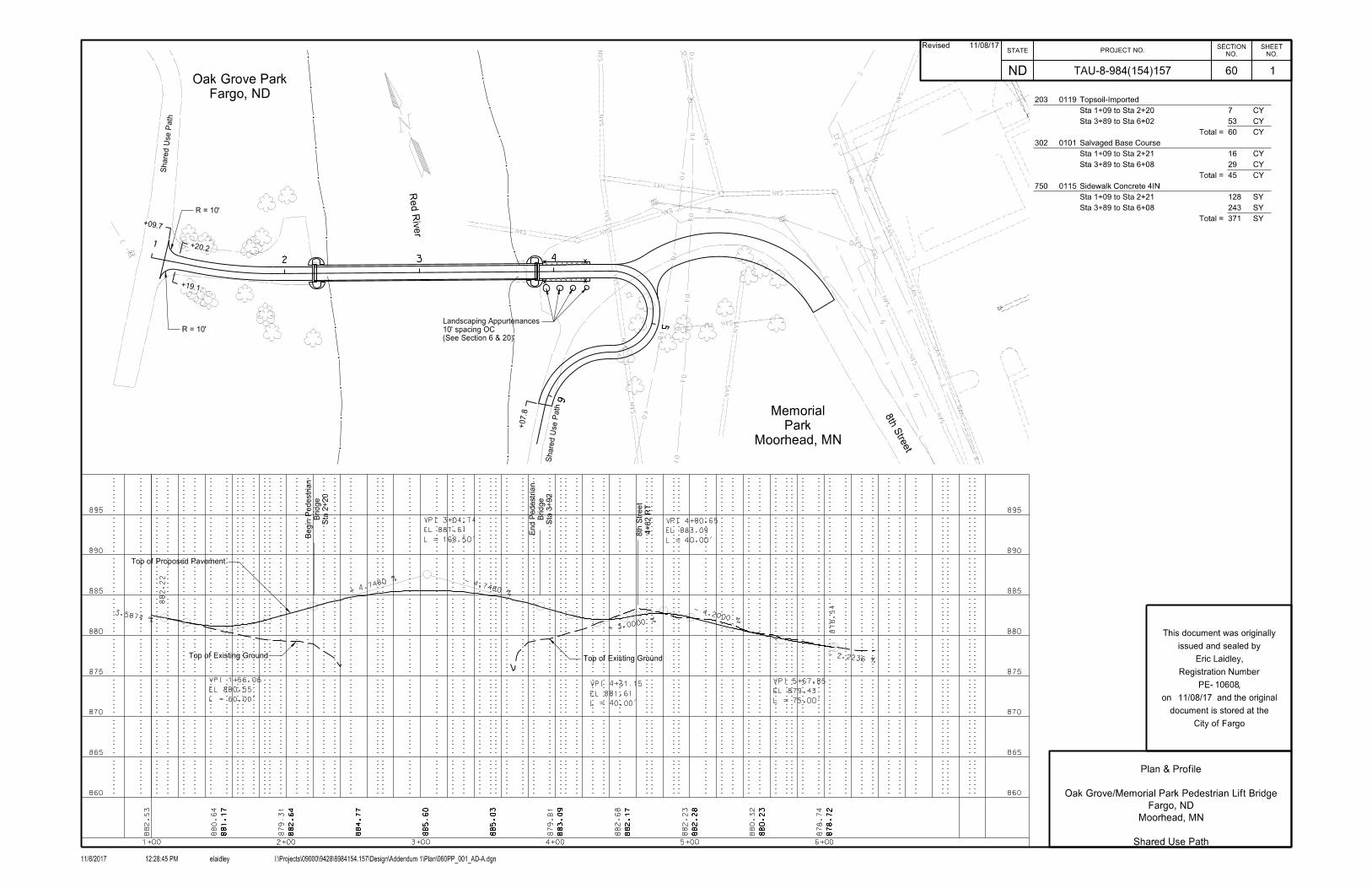
Plan & Profile
Oak Grove/Memorial Park Pedestrian Lift Bridge
Fargo, ND
Moorhead, MN
Shared Use Path
Eric Laidley,
STATE PROJECT NO.
ND
NO.
SHEET
NO.
SECTION
11/8/2017 elaidley I:\Projects\09000\9428\8984154.157\Design\Addendum 1\Plan\060PP_001_AD-A.dgn12:28:45 PM
City of Fargo
document is stored at the
on and the original
PE- ,
Registration Number
issued and sealed by
This document was originally
203 0119 Topsoil-Imported
Sta 1+09 to Sta 2+20 7 CY
Sta 3+89 to Sta 6+02 53 CY
Total = 60 CY
302 0101 Salvaged Base Course
Sta 1+09 to Sta 2+21 16 CY
Sta 3+89 to Sta 6+08 29 CY
Total = 45 CY
750 0115 Sidewalk Concrete 4IN
Sta 1+09 to Sta 2+21 128 SY
Sta 3+89 to Sta 6+08 243 SY
Total = 371 SY
Revised 11/08/17
50
51
52
8th Stre
et
Red River
Share
d U
se P
ath
+63.1
Fargo, ND
Oak Grove Park
Moorhead, MN
Park
Memorial
R = 40'
R = 20'
+15.0
+29.2
882.53
VPI 50+30.00
EL 883.26
+ 2.437
7 %
+ 1
0.00
00 %
L = 40.00'
VPI 51+21.47
EL 892.41
+ 4.6
937 %
L = 80.00'
894.36
Top of Existing GroundTop of Proposed Pavement
50+00 51+00 52+00
883.35
886.62
890.57
893.74
896.01
50+00 51+00
882.53
885.26
890.15
893.70
900
905
870
875
880
885
890
895
10608
11/08/17
60
900
905
870
875
880
885
890
895
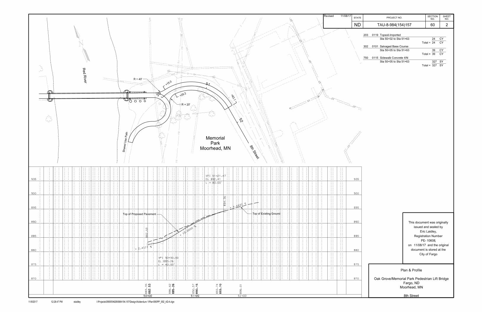
TAU-8-984(154)157 2
Plan & Profile
Oak Grove/Memorial Park Pedestrian Lift Bridge
Fargo, ND
Moorhead, MN
8th Street
203 0119 Topsoil-Imported
Sta 50+02 to Sta 51+63 24 CY
Total = 24 CY
302 0101 Salvaged Base Course
Sta 50+05 to Sta 51+63 39 CY
Total = 39 CY
750 0115 Sidewalk Concrete 4IN
Sta 50+05 to Sta 51+63 327 SY
Total = 327 SY
Eric Laidley,
STATE PROJECT NO.
ND
NO.
SHEET
NO.
SECTION
11/8/2017 elaidley I:\Projects\09000\9428\8984154.157\Design\Addendum 1\Plan\060PP_002_AD-A.dgn12:28:47 PM
City of Fargo
document is stored at the
on and the original
PE- ,
Registration Number
issued and sealed by
This document was originally
Revised 11/08/17

1
2 3 4
5
6
1
1
Oak Grove Park
8th Stre
et
Red River
Share
d U
se P
ath
Share
d U
se P
ath
RWALL1
RWALL2
Park
Memorial
Fence
Removable Pedestrian
PRBRIDGE
Proposed Top of Wall
El. 883.34
Sta. 1+00.00
Begin Wall
El. 881.91
Sta. 1+35.27
Begin Wall
at Front Face of Wall
Top of Existing Ground
Bottom of Concrete Cap
El. 859.50
Bottom of Sheet Pile
RWALL2
Full Length of Wall
Removable Pedestrian Fence
Proposed Top of Wall
El. 883.62
Sta. 1+00.00
Begin Wall
El. 882.19
Sta. 1+35.27
Begin Wall
at Front Face of Wall
Top of Existing Ground
Bottom of Concrete Cap
El. 859.50
Bottom of Sheet Pile
RWALL1
Full Length of Wall
Removable Pedestrian Fence
1+001+00 2+00 2+00
Section 20 for More Information
Note: See Pedestrian Fence Detail in
10608
11/08/17
60
860
865
870
875
880
885
890
855
TAU-8-984(154)157 3
Plan & Profile
Oak Grove/Memorial Park Pedestrian Lift Bridge
Fargo, ND
860
865
870
875
880
885
890
855
Moorhead, MN
Sheet Pile Retaining Walls
Eric Laidley,
STATE PROJECT NO.
ND
NO.
SHEET
NO.
SECTION
11/8/2017 elaidley I:\Projects\09000\9428\8984154.157\Design\Addendum 1\Plan\060PP_003_AD-A.dgn12:28:48 PM
City of Fargo
document is stored at the
on and the original
PE- ,
Registration Number
issued and sealed by
This document was originally
624 0124 Pedestrian Fence
Sta 3+92 to Sta 4+27 LT (PRBRIDGE) 36 LF
Sta 3+92 to Sta 4+27 RT (PRBRIDGE) 36 LF
Total = 72 LF
750 0030 Pigmented Imprinted Concrete
Sta 3+92 to Sta 4+27 LT (PRBRIDGE) 9 SY
Sta 3+92 to Sta 4+27 RT (PRBRIDGE) 9 SY
Total = 18 SY
Revised 11/08/17

DESIGN STRENGTHS:
NAVD 88 DATUM
PLANS ARE BASED ON
ALL ELEVATIONS IN THESE
LRFD Design Method
Fy = 50,000 PSI ~ Structural Steel
fy = 60,000 PSI ~ Reinforcing Steel
f'c = 4,000 PSI ~ Class AE-3 Concrete
Drainage Area
Stream Gradient
Design Frequency
Design Discharge
Design Headwater Stage
Design Tailwater Stage
Velocity Through Bridge
Overtopping Stage
Overtopping Discharge
HYDRAULIC DATA:
sq mi
ft/ft
fps
cfs
yr
cfs
ft
ft
ft
cfs
ft
6,650
0.0000
100
29,300
899.68
899.67
1.2
50,000
903.11
881.30
10,300
500 - Year Frequency Discharge
500 - Year Frequency Headwater
B.O. Steel
500-Yr. Flood
B.O.F.
2'-0" Midspan Camber
PARK (ND)
OAK GROVE
PARK (MN)
MEMORIAL
T.O. Wall
FL
OW
165'-8" Truss Length
L BridgeC
PLAN
ELEVATION
12'-8"
Panel
Aproach
ST-1
(TYP.)
Steel Piling
Grade
Proposed Protection, Typ.
Riprap SlopeTruss Bridge
New Steel
Bridge To Be Removed
Existing Steel Truss
Existing Grade
Panel
Aproach
Safety Rail
Horizontal
(Typ.)
End of Approach Panel
Extend Riprap to
32
End BridgeSta. 3+88.99
883.61' (Grade)Sta. 2+20.49
883.61' (Grade)
Begin Bridge
EL. 872.61'
EL. 890.61'
EL. 903.62'
168'-6" Overall Bridge Length
1'-5" 1'-5"
12'-8"
10'-0"10'-0"
4
EL. 903.12'
Be Removed
Existing Abutment To
Be Removed
Existing Abutment To
Metal Railing - See Section 20
Sheet Pile Retaining Wall &
See Section 20
Slope Protection -
Limits Of Riprap
Riprap Detail
See East Abutment
Slope Protection -
Limits Of Riprap
See Section 20
-West Abutment
Riprap Key at
EL. 877.75
EL. 879.25
EL. Varies
Waterline
10'-0"
4'-6"
Clear
5'-0"5'-0"
L BridgeC
12'-0" (Max.)
DeckingWood
TYPICAL SECTION
Spacing4" Max.
21
5'
GradeExisting
Geotextile Fabric
8'-0"
Max.
880.11'
24"
Bearing Height)(Assumes 6"Low Member
EAST ABUTMENT RIPRAP DETAIL
Front Face of Abutment
Riprap to Extend to
H10 VEHICLE LOADING
CASS COUNTY
D-622-01
CITY OF FARGO
DATE BRIDGE ENGINEER
STANDARD DRAWINGS
BRIDGE LAYOUT
PEDESTRIAN/BICYCLE BRIDGE
AND LIFT TOWERS
90 PSF Pedestrian Live Load
11/06/17
1
PROJECT: TAU-8-984(154)157
STATION: 3+04.74
Matthew J Cramer
7898
D-900-01
City of Fargo
document is stored at the
on and the original
was originally issued and
This document
Registration Number PE-
sealed by
11/06/17REVISIONSTATE
NO.
ND
PROJECT NUMBERSHEET
NO.
SECTION
11/7/2017 ejohnson I:\Projects\09000\9428\8984154.157\Bridge\Plans\Final\North Oak Grove-Memorial\170BR_01_BRLO.dgn9:31:59 AM
170
BN-pageXXXYYXX000
TAU-8-984(154)157
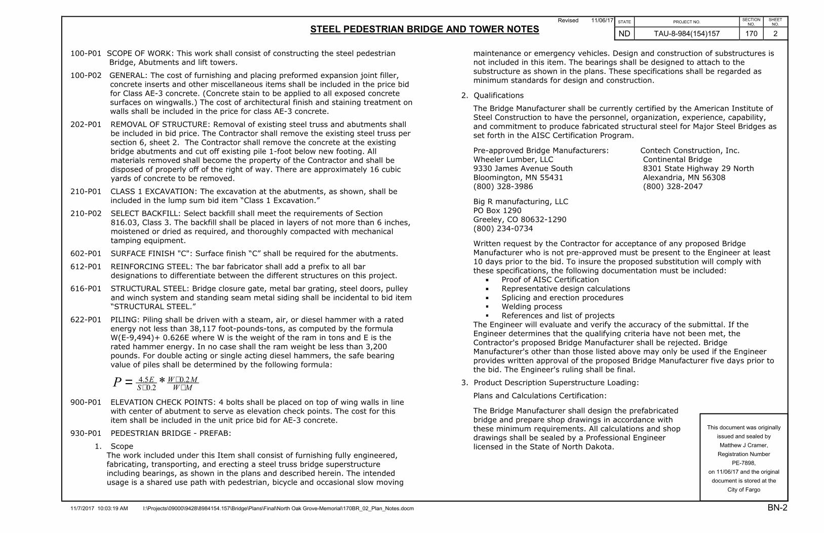
Revised 11/06/17
STEEL PEDESTRIAN BRIDGE AND TOWER NOTES
11/7/2017 10:03:19 AM I:\Projects\09000\9428\8984154.157\Bridge\Plans\Final\North Oak Grove-Memorial\170BR_02_Plan_Notes.docm
STATE PROJECT NO. SECTION
NO. SHEET
NO.
ND TAU-8-984(154)157 170 2
BN-2
This document was originally
issued and sealed by
Matthew J Cramer,
Registration Number
PE-7898,
on 11/06/17 and the original
document is stored at the
City of Fargo
100-P01 SCOPE OF WORK: This work shall consist of constructing the steel pedestrian Bridge, Abutments and lift towers.
100-P02 GENERAL: The cost of furnishing and placing preformed expansion joint filler, concrete inserts and other miscellaneous items shall be included in the price bid
for Class AE-3 concrete. (Concrete stain to be applied to all exposed concrete surfaces on wingwalls.) The cost of architectural finish and staining treatment on walls shall be included in the price for class AE-3 concrete.
202-P01 REMOVAL OF STRUCTURE: Removal of existing steel truss and abutments shall be included in bid price. The Contractor shall remove the existing steel truss per
section 6, sheet 2. The Contractor shall remove the concrete at the existing bridge abutments and cut off existing pile 1-foot below new footing. All materials removed shall become the property of the Contractor and shall be
disposed of properly off of the right of way. There are approximately 16 cubic yards of concrete to be removed.
210-P01 CLASS 1 EXCAVATION: The excavation at the abutments, as shown, shall be included in the lump sum bid item “Class 1 Excavation.”
210-P02 SELECT BACKFILL: Select backfill shall meet the requirements of Section
816.03, Class 3. The backfill shall be placed in layers of not more than 6 inches, moistened or dried as required, and thoroughly compacted with mechanical
tamping equipment.
602-P01 SURFACE FINISH "C": Surface finish “C” shall be required for the abutments.
612-P01 REINFORCING STEEL: The bar fabricator shall add a prefix to all bar designations to differentiate between the different structures on this project.
616-P01 STRUCTURAL STEEL: Bridge closure gate, metal bar grating, steel doors, pulley
and winch system and standing seam metal siding shall be incidental to bid item “STRUCTURAL STEEL.”
622-P01 PILING: Piling shall be driven with a steam, air, or diesel hammer with a rated energy not less than 38,117 foot-pounds-tons, as computed by the formula W(E-9,494)+ 0.626E where W is the weight of the ram in tons and E is the
rated hammer energy. In no case shall the ram weight be less than 3,200 pounds. For double acting or single acting diesel hammers, the safe bearing
value of piles shall be determined by the following formula:
MW
MW
S
EP ++
+= 2.0
2.0
5.4 *
900-P01 ELEVATION CHECK POINTS: 4 bolts shall be placed on top of wing walls in line with center of abutment to serve as elevation check points. The cost for this
item shall be included in the unit price bid for AE-3 concrete.
930-P01 PEDESTRIAN BRIDGE - PREFAB:
1. Scope
The work included under this Item shall consist of furnishing fully engineered, fabricating, transporting, and erecting a steel truss bridge superstructure
including bearings, as shown in the plans and described herein. The intended usage is a shared use path with pedestrian, bicycle and occasional slow moving
maintenance or emergency vehicles. Design and construction of substructures is not included in this item. The bearings shall be designed to attach to the
substructure as shown in the plans. These specifications shall be regarded as minimum standards for design and construction.
2. Qualifications
The Bridge Manufacturer shall be currently certified by the American Institute of Steel Construction to have the personnel, organization, experience, capability,
and commitment to produce fabricated structural steel for Major Steel Bridges as set forth in the AISC Certification Program.
Pre-approved Bridge Manufacturers: Contech Construction, Inc. Wheeler Lumber, LLC Continental Bridge 9330 James Avenue South 8301 State Highway 29 North
Bloomington, MN 55431 Alexandria, MN 56308 (800) 328-3986 (800) 328-2047
Big R manufacturing, LLC PO Box 1290 Greeley, CO 80632-1290
(800) 234-0734
Written request by the Contractor for acceptance of any proposed Bridge
Manufacturer who is not pre-approved must be present to the Engineer at least 10 days prior to the bid. To insure the proposed substitution will comply with
these specifications, the following documentation must be included: � Proof of AISC Certification � Representative design calculations
� Splicing and erection procedures � Welding process
� References and list of projects The Engineer will evaluate and verify the accuracy of the submittal. If the Engineer determines that the qualifying criteria have not been met, the
Contractor's proposed Bridge Manufacturer shall be rejected. Bridge Manufacturer's other than those listed above may only be used if the Engineer
provides written approval of the proposed Bridge Manufacturer five days prior to the bid. The Engineer's ruling shall be final.
3. Product Description Superstructure Loading:
Plans and Calculations Certification:
The Bridge Manufacturer shall design the prefabricated
bridge and prepare shop drawings in accordance with these minimum requirements. All calculations and shop drawings shall be sealed by a Professional Engineer
licensed in the State of North Dakota.

Revised 11/06/17
STEEL PEDESTRIAN BRIDGE AND TOWER NOTES
11/7/2017 10:03:19 AM I:\Projects\09000\9428\8984154.157\Bridge\Plans\Final\North Oak Grove-Memorial\170BR_02_Plan_Notes.docm
STATE PROJECT NO. SECTION
NO. SHEET
NO.
ND TAU-8-984(154)157 170 3
BN-3
This document was originally
issued and sealed by
Matthew J Cramer,
Registration Number
PE-7898,
on 11/06/17 and the original
document is stored at the
City of Fargo
Applicable Codes:
Design shall be governed by the current design specifications of the American
Association of State Highway and Transportation Officials (AASHTO), supplemented with the current edition of American Institute of Steel Construction
(AISC) including the Design Specification for Steel Hollow Structural Sections, further supplemented with the current edition of American Welding Society (AWS) D1.1 Structure Welding Code, as modified and further supplemented
herein. Structural members shall be designed in accordance with recognized engineering practices and principles.
Truss Style:
The truss type shall be as determined by the Bridge Manufacturer with a web member style as determined by the Bridge Manufacturer.
Pratt or Howe style trusses with an odd number of bays shall have crossed diagonals in the middle bay. Any crossed diagonals shall be of equal dimension.
Overhead (portal) bracing is prohibited.
Span length = 165'-8" measured out-to-out of bridge superstructure.
Max Gross Bridge Weight = 110,000 lbs.
Camber:
The bridge shall be cambered per sheet number 1 with additional camber to
offset the calculated dead load deflection.
Deck Width:
Bridge clear deck width = 10'-0" as measured between the inside face of the railing or structural elements other than handrails.
Geometry Limitations:
Abutment backwall height = 4’-0" Abutment bridge seat width = 1'-10”
Maximum Bridge Dimensions (O.D.) = 12’-0” W x 8’-0” H Top of deck elevation (at Oak Grove) = 883.61’ Top of deck elevation (at Memorial) = 883.61’
Station at midpoint of bridge = 3+04.74
Superstructure Loading:
In addition to dead, live (pedestrian), water (buoyancy and stream pressure), and wind loads as specified by AASHTO, the bridge shall be designed to accommodate the following loads:
� Point Load = 1000 lbs. plus impact, applied at a single point
� Vehicle Load AASHTO H10
For occasional slow moving maintenance or emergency vehicles impact is not required.
Vibration:
The vibration design for this bridge shall be a level two design. For level two design, the peak acceleration of the truss and of deck systems shall be limited to
5% gravity. Peak acceleration shall be computed based on a constant force of 92 pounds, and a damping ratio of 0.01. Peak acceleration of the truss and of deck
systems may be computed independently without consideration of a combined effect. Peak acceleration in deck systems shall be computed with consideration of the combined effect of longitudinal components and floor beams.
Deflection:
Wind deflections of the truss, as measured at deck level, shall be limited to
L/500. Deflections in transverse deck framing due to point or truck load shall be limited to L/300 or 0.1". Impact shall be included in deflection checks as applicable.
Deflection of the truss due to uniform live load shall be limited to L/500. Deflections in longitudinal deck members due to uniform live load shall be limited
to L/500. No other service deflection limits need be considered.
Truss and Lift Tower Material:
All members of the truss and deck system shall be fabricated from
square/rectangular hollow structural sections (HSS) with the exception that floor beams may be wide flange (W) shapes. Open ends of end posts and floor beams
shall be capped. Open shaped (non-tubular) stringers will be allowed only when the Bridge Manufacturer warranties the stringer design for 50% overload.
Steel material shall be corrosion resistant high-strength low-alloy material meeting ASTM A242, A588, A606, or A847 with a minimum corrosion index of 5.8 per ASTM G101.
Minimum thickness of tubular steel members (not including railings) shall be 1/4-inch for primary truss members and 3/16-inch elsewhere. Where water
collection inside of structural tubing is possible during construction or service, weep holes shall be provided at low points.
Steel Finish:
All exposed steel surfaces of lift towers and gate shall be painted after fabrication per section 616 of the NDDOT standard specification. Color to match federal color
"Brown" number 30045, and shall meet federal standard no. 595B colors. All costs associated with painting shall be included in the unit price bid for Structural Steel. Any required re-coating will be done by the contractor, subject to the
engineer’s approval. Bridge is uncoated.

Revised 11/06/17
STEEL PEDESTRIAN BRIDGE AND TOWER NOTES
11/7/2017 10:03:19 AM I:\Projects\09000\9428\8984154.157\Bridge\Plans\Final\North Oak Grove-Memorial\170BR_02_Plan_Notes.docm
STATE PROJECT NO. SECTION
NO. SHEET
NO.
ND TAU-8-984(154)157 170 4
BN-4
This document was originally
issued and sealed by
Matthew J Cramer,
Registration Number
PE-7898,
on 11/06/17 and the original
document is stored at the
City of Fargo
Field Splice:
Field splices shall be fully bolted slip critical connections, and utilizing tension
indicating washers is optional. Tack welding of high strength hardware is prohibited. Splices not immediately at or adjacent to panel points shall be
designed for 100 percent of the member bending moment capacity for primary compression members, and 75 percent for bracing members or tension members subject to load reversal, including slip resistance, and slip resistance shall further
meet the same AASHTO required strength as with other failure modes.
Splices for truss members, bracing, and floor beams, shall be made with Type 3
bolts. Exposed portions of type 3 bolts shall be painted with like color of material being bolted.
Handrail:
Handrails shall be galvanized steel or aluminum. Actual outside diameter shall be 1 1/4-inch minimum, 1 1/2-inch maximum. The top of the handrail shall be 36-
inches plus or minus 2-inches above the deck surface. The handrail shall have a minimum 1 1/2-inch knuckle space, shall not rotate within fittings, and shall have returns at each end.
Decking:
The bridge deck shall be ACQ pressure treated douglas fir with thickness and reinforcement to be determined by the bridge manufacturer. Deck fastening
systems shall be designed to resist all uplift forces determined in accordance with AASHTO Specifications.
Bolting:
All bolts shall be 7/8” φ A325 Type 3 bolts unless noted otherwise.
Welding:
Welding and weld qualification tests shall conform to the provisions of AWS D1.1.
The flux core arc welding (FCAW) process, utilizing E70 electrodes with similar weathering characteristics as the base material, shall be used. Welding operators
shall be properly accredited experienced operators. Each shall have certification of satisfactorily passing AWS standard qualification tests for the 3G and/or 4F position(s), evidence of experience and skill in welding structural steel, and have
demonstrated the ability to make acceptable welds of the type required.
Non-destructive weld testing is required. Testing will be performed by a
independent ASNT Level II Technician or greater and be paid for by the owner. All welds are to be 100 percent visually inspected. Ten percent (10%) of all fillet and partial penetration welds shall be magnetic particle tested. For arch type
bridges, 100 percent of end of top chord to bottom chord connections shall be tested. Full penetration shop welds shall be Ultrasonic tested in accordance with
AWS D1.1; Section 6. Base material certifications are to be supplied by the material suppliers. Inspection test results shall be submitted to the engineer.
Other requirements:
Self-tapping and self-drilling screws are not acceptable for any portion of the
bridge structure.
Cover plates shall be provided to cover expansion gaps. Cover plates shall fit
tight to the top of the abutment backwall without any bridge weight bearing on the backwall. Consider joint size and weight of vehicles when determining plate thickness.
Bridge bearing system shall be designed and supplied by the bridge manufacturer.
The anchor systems shall be designed and supplied by the Bridge Manufacturer. Cast in place anchors or drilled anchors installed with an approved chemical adhesive system shall be used for anchorage. Anchor bolts shall conform to
ASTM A307, A193, or F1554.
All hardware (other than type 3 high strength) shall be hot-dip galvanized in
accordance with ASTM A153.
Cementitious non-shrink grout, when applicable, shall meet ASTM C-1107, 7000 psi minimum.
Materials not specified shall conform to applicable ASTM or AASHTO specifications.
4. Submittals
The Bridge Manufacturer & Structural Steel fabricator shall prepare and submit
six (6) sets of shop drawings and structural calculations (bridge only) and obtain approval prior to beginning fabrication. Shop drawings shall be unique drawings prepared to illustrate the specific portion of the work to be done. All relative
design information including but not omitted to governing codes, design details, dimensions related to substructures and general notes shall be clearly specified
on the drawings. Shop drawings shall be accurately prepared by skilled drafters to be complete in every respect. Drawings shall have cross-referenced details and sheet numbers.
The Bridge Manufacturer & Structural Steel fabricator shall submit a certificate of compliance stating that all materials and fabrication are in compliance with the
contract documents and applicable codes.
5. Delivery
The Contractor shall coordinate with the Bridge Manufacturer in the delivery and
erection schedule. The Bridge Manufacturer shall provide detailed, written instruction procedures for proper lifting
and splicing of bridge components.
SHOP DRAWINGS: The Contractor shall submit the following shop drawings to the Engineer for review:
� 1. Bridge
� 2. Bridge Bearing

PILE COORDINATES
PILE NORTHING EASTING
A
B
C
D
E
F
G
H
5
LEGEND
- HP10 x 42 Pile
Direction Of 4" Horizontal To 12" Vertical Batter
NOTE:
HP10 x 42 Piles Shall Be Driven To 110 Tons.
BEARING ELEVATIONS
Of Changes In Submittals.
Manufacturing Requirements. Make Note
*Elevations May Vary Based On Bridge
464079.33
464060.72
464076.04
464057.42
464020.01
464016.72
464001.40
463998.11
2901106.50
2901099.18
2901114.88
2901107.56
2901257.25
2901265.63
2901249.93
2901258.30
SPEC CODE ITEM DESCRIPTIONUNIT QUANTITY
202 0105 REMOVAL OF STRUCTURE L SUM 1
210 0101 CLASS I EXCAVATION L SUM 1
210 0201 FOUNDATION PREPARATION EA 1
602 0130 CLASS AE-3 CONCRETE CY 180
612 0115 LBS
616 0360 STRUCTURAL STEEL LBS 55320
622 STEEL PILING HP 10 X 42 LF 2730
256 0200 CY
709 0600 GEOTEXTILE FABRIC - TYPE RR SY
930 3000 BRIDGE BENCH MARKS SET 1
930 9750 PEDESTRIAN BRIDGE - PRE-FAB EA 1
375
0020
191
REINFORCING STEEL-GRADE 60
930 9677 RELOCATE TRUSS BRIDGE L SUM 1
622 SF 16906760 STEEL SHEET PILING
612 0116 LBS 18880REINFORCING STEEL-GRADE 60-EPOXY COATED
9420
RIPRAP GRADE II
L Piling
HP10 x 42 x 105'
C
A C
B D
Abutment No. 1
Abutment No. 1
1'-3" 7'-9"
10'-0"
10'-0"
3'-0"3'-0"1'-9"
3'-0"
4'-0"
3'-0"
3'-0"
7'-0"
2
2
*El. 879.61' @ Concrete
Sta. 2+20.49
Begin Bridge
(Backwall)
El. 882.94'
Sta. 2+20.49
Begin Bridge
(Backwall)
El. 882.94'
3'-0"1'-6"
168'-6" Overall Bridge Length
PILING LAYOUT
L Piling
HP10 x 42 x 105'
C
E G
F H
` Of Pedestrian Bridge
` Of Pedestrian Bridge
Abutment No. 2
Abutment No. 2
E
F
7'-9" 1'-3"
10'-0"
10'-0"
3'-0"
4
Sta. 3+88.99
End Bridge
(Back Wall)
El. 882.94'
Sta. 3+88.99
End Bridge
(Back Wall)
El. 882.94'
*El. 879.61' @ Concrete
4 3'-0"
7'-0"
4'-0"
3'-0"
3'-0" 1'-9"3'-0"
3'-0" 1'-6"
Pedestrian/Bicycle Bridge
Lift Towers
BEARING ELEVATIONS
& PILE LAYOUT
11/06/17
Matthew J Cramer
7879
City of Fargo
document is stored at the
on and the original
was originally issued and
This document
Registration Number PE-
sealed by
REVISION 11/06/17STATE
NO.
ND
PROJECT NUMBERSHEET
NO.
SECTION
11/7/2017 ejohnson I:\Projects\09000\9428\8984154.157\Bridge\Plans\Final\North Oak Grove-Memorial\170BR_05_PILELO&BRG.dgn9:32:02 AM
170
BN-pageXXXYYXX000
TAU-8-984(154)157
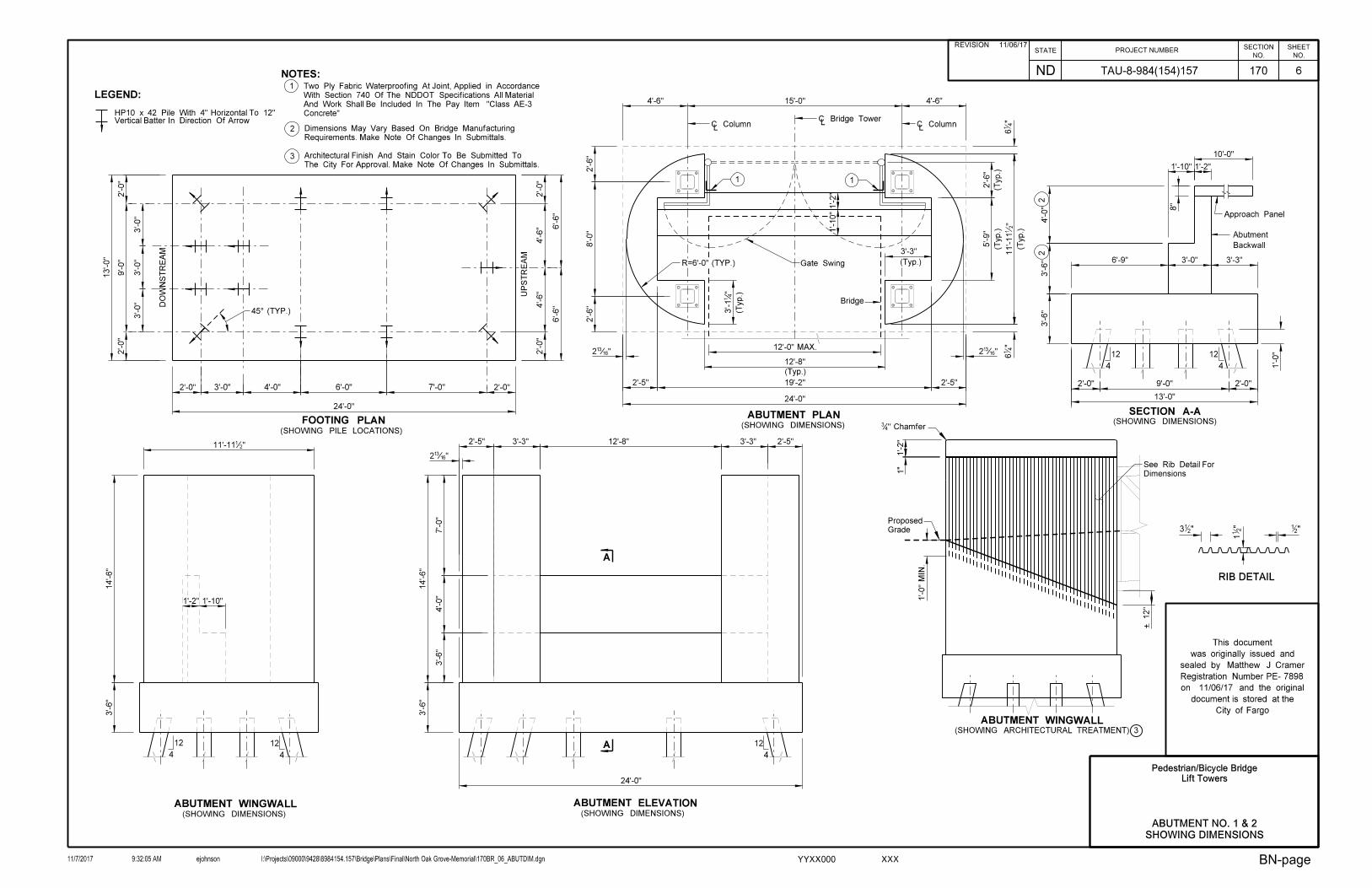
6
LEGEND:
Vertical Batter In Direction Of ArrowHP10 x 42 Pile With 4" Horizontal To 12"
SECTION A-A
ABUTMENT WINGWALL(SHOWING DIMENSIONS)
(SHOWING DIMENSIONS)FOOTING PLAN(SHOWING PILE LOCATIONS)
(SHOWING DIMENSIONS)
ABUTMENT PLAN24'-0"
2'-0"
13'-0"
4
12
1'-0"
13'-0"
6'-9" 3'-0" 3'-3"
3'-6"
1'-2"
1'-10"
24'-0"
3'-3"
(Typ.)
(Typ.)
1'-2"1'-10"
3'-6"
14'-6"
1'-10"1'-2"
11'-11•"
4'-0"
(Typ.)
1
(Typ.)
(Typ.)
5'-9"
2'-0"2'-0"9'-0"2'-0"
1
12'-8"
11'-11•"
2'-0"
9'-0"
2'-0"
4
12
3'-6"
3'-1‚"
ABUTMENT WINGWALL(SHOWING ARCHITECTURAL TREATMENT)
19'-2"
45° (TYP.)
2'-5" 2'-5"
R=6'-0" (TYP.)
4
12
10'-0"
8"
1'-0"
MIN.
1'-2"
4'-0" 6'-0" 7'-0"3'-0"
DO
WN
ST
RE
AM
UP
ST
RE
AM
+ 12"
2Ž" 2Ž"
3'-0"
3'-0"
3'-0"
2'-6"
8'-0"
2'-6"
C Bridge TowerL
LC Column
LC Column
4'-6"15'-0"4'-6"
Gate Swing
Bridge
22
2
3
3The City For Approval. Make Note Of Changes In Submittals.
Architectural Finish And Stain Color To Be Submitted To
Requirements. Make Note Of Changes In Submittals.
Dimensions May Vary Based On Bridge Manufacturing
(SHOWING DIMENSIONS)
A
24'-0"
A
14'-6"
3'-6"
ABUTMENT ELEVATION
4
12
3'-3" 3'-3"2'-5" 12'-8" 2'-5"7'-0"
4'-0"
3'-6"
4
12
NOTES:
1
Concrete"
And Work Shall Be Included In The Pay Item "Class AE-3
With Section 740 Of The NDDOT Specifications All Material
Two Ply Fabric Waterproofing At Joint, Applied in Accordance
Dimensions
See Rib Detail For
Grade
Proposed
12'-0" MAX.
Backwall
Abutment
1"
ƒ" Chamfer
Approach Panel
2Ž"
6'-6"
6'-6"
2'-0"
4'-6"
4'-6"
2'-0"
"4
16
"4
16
(Typ.)
2'-6"
RIB DETAIL
"213 "2
1"2
11
Pedestrian/Bicycle Bridge
Lift Towers
ABUTMENT NO. 1 & 2
SHOWING DIMENSIONS
11/06/17
Matthew J Cramer
7898
City of Fargo
document is stored at the
on and the original
was originally issued and
This document
Registration Number PE-
sealed by
11/06/17REVISIONSTATE
NO.
ND
PROJECT NUMBERSHEET
NO.
SECTION
11/7/2017 ejohnson I:\Projects\09000\9428\8984154.157\Bridge\Plans\Final\North Oak Grove-Memorial\170BR_06_ABUTDIM.dgn9:32:05 AM
170
BN-pageXXXYYXX000
TAU-8-984(154)157

7
ABUTMENT WINGWALL
FOOTING PLAN(SHOWING REINFORCEMENT)
A
A
13'-0"
24'-0"
6" 6"
6"
6"
(SHOWING REINFORCEMENT)
B
B
5XE100 Back Face5XE100 Back Face
5XD101 Back Face
6XB101 Back Face
Face
(SHOWING STEM REINFORCEMENT)
ABUTMENT PLAN(SHOWING REINFORCEMENT)
5XD101
5XD100
ABUTMENT ELEVATION
CC
ABUTMENT ELEVATION C-C
Top
Bottom
5XA105 Front
Face
6XA108 Back Face
5XD101 Back Face5XD101 Back Face
5XE100
12 Spaces @ 1'-0"
Spaces
4 Equal
31 Spaces @ 3" Max.
12 Equal Spaces ~ 6
A102 (T
op)
2 Additional
6XA107
3"3" 4 Equal
Spaces
24 Equal Spaces ~ 10F100 (Btm.)
23 Spaces @ 1'-0" ~ 8F101 (Btm.)
6XA104 Back Face
4XC102 4XC102
4XC100
NOTES:
1
1
(Typ.)
(Typ.)
UP
ST
RE
AM
DO
WN
ST
RE
AM
4XC103
4XC103
NOTES:
1
5 Spaces5 Spaces
@ 10‚" @ 10‚"
Shown For Clarity.
Vertical Wall Reinforcement Not
5XD100
5XD101
5XD100 Front Face5XD100 Front Face
5XD100 Front Face
5XE1005XE100
5XE1005XE100
5XE100
4XC102
4XC100
4XC102
4XC103
4XC103
4XC103
6XA107
4-6XA108
4-6XA107
(Typ.)
30-6XB101 Dowel
30-6XA109 Vert &
8XA110
6XA109 Or
6XA107 Front Face
23 Spaces @ 1'-0" ~ 6A100 (Top)
5XC101 Front Face
Column Anchor Bolt
5-5XA105
5-5XA106
5XA106 Back
5XA111 Front Face
5XA111 Front Face
3" Along Arc. (Typ.)
32-8XB102 Dowel @
32-8XA110 Vert &
5XB100 Front Face
(SHOWING WINGWALL REINFORCEMENT)
8XB102
6XB101 Or
2
Spacing Along Arc
Sheet 8
Reinforcement Detail On
Reinforced Piles. See Pile
2
(Typ.)
5XC104
(Typ.)
6"
Not Labeled
Reinforcement
For Stem Vertical
Elevation C-C
See Abutment
Pedestrian/Bicycle Bridge
Lift Towers
ABUTMENT NO. 1 & 2
SHOWING REINFORCEMENT
11/06/17
Matthew J Cramer
7898
City of Fargo
document is stored at the
on and the original
was originally issued and
This document
Registration Number PE-
sealed by
11/06/17REVISIONSTATE
NO.
ND
PROJECT NUMBERSHEET
NO.
SECTION
11/7/2017 ejohnson I:\Projects\09000\9428\8984154.157\Bridge\Plans\Final\North Oak Grove-Memorial\170BR_07_ABUTREINF1.dgn9:32:08 AM
170
BN-pageXXXYYXX000
TAU-8-984(154)157
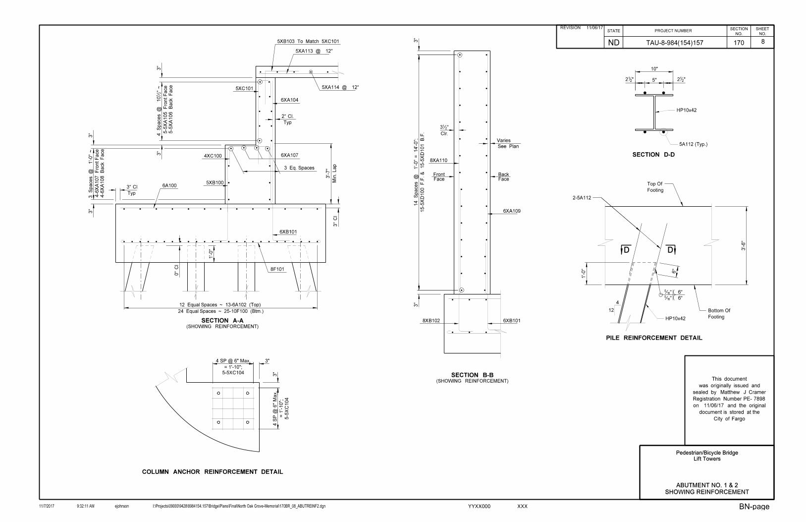
8
Pedestrian/Bicycle Bridge
Lift Towers
ABUTMENT NO. 1 & 2
SHOWING REINFORCEMENT
11/06/17
Matthew J Cramer
7898
City of Fargo
document is stored at the
on and the original
was originally issued and
This document
Registration Number PE-
sealed by
11/06/17REVISION
6"
4
12
Š" 6"
PILE REINFORCEMENT DETAIL
6"Š"
D D
HP10x42 Footing
Bottom Of
Footing
Top Of
2-5A112
1'-0"
3'-6"
HP10x42
"2125""2
12
10"
SECTION D-D
5A112 (Typ.)
15-5
XD100 F.F.
& 15-5
XD101
B.F.
14 Spaces
@
1'-0"
= 14'-0";
SECTION A-A(SHOWING REINFORCEMENT)
0"
Cl
Typ
2" Cl.
Typ
(SHOWING REINFORCEMENT)
SECTION B-B
FaceFront
FaceBack
3"
3"
3 Spaces
@
1'-0"
~
3"
4 Spaces
@
10•"
~3"
3 Eq. Spaces
8F101
Varies
See Plan
6XA104
6XA109
6XA107
4-6
XA108
Back Face
4-6
XA107 Fro
nt Face
6A100
5XB103 To Match 5XC101
5XA113 @ 12"
5XA114 @ 12"
5-5
XA106
Back Face
5-5
XA105 Fro
nt Face
4XC100
5XB100
5XC101
6XB101
6XB1018XB102
8XA110
Clr.
3•"
24 Equal Spaces ~ 25-10F100 (Btm.)
12 Equal Spaces ~ 13-6A102 (Top)
1'-0"
Min. Lap
3'-7"
3"
3"
3"
Cl
3" Cl
STATENO.
ND
PROJECT NUMBERSHEET
NO.
SECTION
11/7/2017 ejohnson I:\Projects\09000\9428\8984154.157\Bridge\Plans\Final\North Oak Grove-Memorial\170BR_08_ABUTREINF2.dgn9:32:11 AM
170
BN-pageXXXYYXX000
TAU-8-984(154)157
COLUMN ANCHOR REINFORCEMENT DETAIL
5-5XC104
5-5
XC104
= 1'-10";
4 SP @ 6" Max.
= 1'-10";
4 S
P @ 6"
Max.
3"
3"

9
NOTES:
1
2
3
4.
Provide Weep Holes At Base Of HSS Columns.
B.O.F. Denotes Bottom Of Footing
5
A.
B.
C.
D.
E.
F.
G.
H.
A.
B.
C.
D.
E.
F.
G.
Interlocking Sheets 22 Gauge, Grade 50 Material.
Prefinished Metal Siding Shall Be 1•" Deep x 18" Wide
Lower Bridge Support Beam to Rest on Tower Structure.
Lower Bridge To The Abutment.
Raise Support Beam Using 2000lb Electric Cable Hoist.
Lift Bridge To Provide Clearance For Support Beam To Rotate Up.
Open Gates And Block Entrances To Bridge At Each End.
Clear Of Pedestrians And Other Obstructions.
Verify Towers, Bridge, And Surrounding Area Are
Clear Bridge Of Snow And Ice.
Lowering Procedure:
Close and Lock Steel Gates At Each End Of Bridge.
Lower Bridge Onto Support Beam.
Lower Bridge Support Beam Once Bridge Has Cleared Beam.
Lift Bridge Using Electric Hoist System.
Raise Bridge Support Beam Using 2000lb Electric Cable Hoist.
Block Entrance To Bridge At Each End.
Clear Of Pedestrians And Other Obstructions.
Verify Towers, Bridge, And Surrounding Area Are
Clear Bridge Of Snow And Ice.
Lifting Procedure:
Bridge Is By Contractor. Submit Details For Approval.
Spreader Beam, Lift Cables And Attachment To
See Electrical For Additional Requiements.
Electric Cable Hoist With 40-Ton Operating Capacity
BACK ELEVATION
26'-5•"
Envelope
Clearance
Steel Piling, Typ.
B.O.F.
See Sheet 1
5
A A
8'-7"
Metal Siding And Roofing
Prefinished Standing Seam
3D D
2'-0"
C C
FRONT ELEVATION
B B
2
Envelope
Clearance
Steel Piling, Typ.
B.O.F.
See Sheet 1
(Typ.)
See Detail L
5
A A
8'-7" Tower
Painted To Match
3' x 7' Steel Door
D D
2'-0"
C C
3'-10•"
Gate
Locking Steel
•" Filler Plate & Bolt
BRIDGE
CLOSED
BRIDGE
CLOSED
5
10'-0"
Min.
Bridge at All Times
Remain Attached to
Spreader Beam to
W12x45 W12x45
2
of Grab Railing
3'-6" to Center
5
HSS 4x4x‚"
L4x4x…"
L4x4x…"
L4x4x…"
(Typ. @ Roof)
HSS 4x2x‚"
1
15'-1"
15'-1"
1†
"
(Typ.)
"HSS 4x4x‚
Metal Siding And Roofing
Prefinished Standing Seam
3(Typ. @ Roof)
HSS 4x2x‚"
1
(Sim.)
See Detail L
W12x45
(Typ.)
L6x6x†"
(TYP.)
HSS 12x12x…"
1†
"
T.O. Wall
El. 890.61
T.O. Wall
El. 890.61
500-Yr. Flood
El. 903.12
Ref. Line
El. 932.29
Ref. Line
El. 932.29
(Typ.)
L6x6x†"
(TYP.)
HSS 12x12x…"
(Typ.)
L6x6x†"
C8x13.7
W12x45
(Typ.)
L6x6x†"
W12x45
Ref. Line
El. 902.12
(Typ.)
Each Side of Web
•" Stiffener Plate
15'-1"
"2
111'-4
HSS 4x4x‚"
45°
•" Filler Plate & Bolt (Typ.)
Pedestrian/Bicycle Bridge
Lift Towers
LIFT TOWER ELEVATIONS
11/06/17
Matthew J Cramer
7898
(Sheet 1 of 2)
City of Fargo
document is stored at the
on and the original
was originally issued and
This document
Registration Number PE-
sealed by
11/06/17REVISIONSTATE
NO.
ND
PROJECT NUMBERSHEET
NO.
SECTION
11/7/2017 ejohnson I:\Projects\09000\9428\8984154.157\Bridge\Plans\Final\North Oak Grove-Memorial\170BR_09_TOWERELEV1.dgn9:32:13 AM
170
BN-pageXXXYYXX000
TAU-8-984(154)157
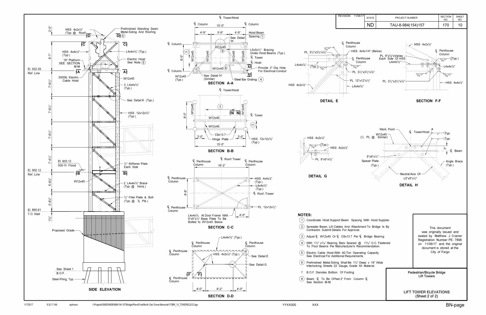
10
NOTES:
1
2
3
4
5
6
7.
See Section M-M.
Beam ` To Be Offset 2" From Column `.
B.O.F. Denotes Bottom Of Footing
Interlocking Sheets 22 Gauge, Grade 50 Material.
Prefinished Metal Siding Shall Be 1•" Deep x 18" Wide
See Electrical For Additional Requirements.
Electric Cable Hoist With 40-Ton Operating Capacity
To Floor Beams Per Manufacturer's Recommendation.
With 1•" x‰" Bearing Bars Spaced @ 1‰" O.C. Fastened
Adjust ` W12x40 Or ` C8x13.7 Per ` Bridge Bearing.
Contractor. Submit Details For Approval.
Spreader Beam, Lift Cables And Attachment To Bridge Is By
Coordinate Hoist Support Beam Spacing With Hoist Supplier.
8
Š"
PL 3•"x3•"x…"
Š"
Š"(Typ.)
Column
C PenthouseL
(Typ.)Š"
PL 3•"x3•"x…"
Š"
PL 3•"x3•"x…"
Š"
Š"(Typ.)
Column
C PenthouseL
Column
C PenthouseL
HSS 4x4x1/4" (Below)
Each Side Of HSS
Typ.
W12x45(• PL @ Similar)
` Tower/HoistTyp.
DETAIL G
DETAIL H
DETAIL E SECTION F-F
(Typ.)
Angle Brace
HSS 4x2x‚"
HSS 4x2x‚"
PL 9"x5"x…"
L4x4x…"
HSS 4x2x‚"L4x4x…"
PL 12"x12"x•"
L4x4x…"
PL 6"x…"xVaries
HSS 4x4x‚"
L4x4x…"
HSS 4x2x‚"
` Beam
3"
(Typ.)
Spacer Plate
5"x9"x•"
Work Point
L5"x5"x•"
Neutral Axis Of
SIDE ELEVATION
B.O.F.
See Sheet 1
Proposed Grade
7'-4•"
8'-7"
AA
B B
(Typ. @ Horiz.)
CC
Metal Siding And Roofing
Prefinished Standing Seam
See Note
Electric Hoist
Steel Piling, Typ.
2'-0"
M-M
SEE SECTION
18" Platform
D D
Pts.)31(Typ. @
•" Filler Plate & Bolt
Cable Hoist
2000lb Electric
7'-6•"
7'-6•"
6
5
W12x45
7'-6•"
Each Side
•" Stiffener Plate
W12x45
1†
"
T.O. Wall
El. 890.61
Ref. Line
El. 902.12
Ref. Line
El. 932.29
500-Yr. Flood
El. 903.12
5'-8‚"
5'-8‚"
2 L4x4x…" Brace
(Typ.)
2 L4x4x…"
(Typ.)
"HSS 4x4x‚ L4x4x…" (Typ.)
(Typ. @ Roof)
HSS 4x2x‚"
See Detail K (Typ.)
(Typ.)
HSS 12x12x…"
15'-0"
8'-0"
L Tower/HoistC
CL Tower
W12x45
W12x45
W12x45
W12x40
3
3
C
16'-2"
8'-8"
C
C
Hinge Plate
C
C
Column
L Penthouse C
Column
L Penthouse
L Roof /Tower
Column
L Penthouse
Column
L Penthouse
SECTION A-A
SECTION B-B
SECTION C-C
SECTION D-D
LL
L
L
4'-0" 4'-0"8'-2"
L Roof/ Tower
4'-0"
3'-0"
C
15'-0"
8'-0"
CL Tower
CL Hoist
Hoist Beam
Spacing
4'-9" 4'-9"5'-6"
1
W12x45
W12x45
W12x45
W12x45
W12x45
W12x45
CC L ColumnL Column
CL Column
CL Column
Steel Bar Grating 4
3
'H'
See Detail
(Similar)
See Detail 'H'
L Tower/Hoist
3'-0"
For Electrical Conduit
Provide 2" Dia. Hole
Column
C Penthouse
Column
C Penthouse
Column
C Penthouse
Column
C Penthouse
L4x4x…" (Typ.)
HSS 4x2x‚" (Typ.)See Detail E
See Detail G
Bolted to W12x45 Below.
5"x5"x•" Base Plate To Be
L4x4x… At Door Frame With
(Typ.)
HSS 4x4x‚"
(Typ.)
L4x4x…"
PL 12x12x•"
(Typ.)
HSS 12x12x…"
C8x13.7
N N
F F
M
M
Under Hoist Beams (Typ.)
L5x5x•" Bracing
8
8
(Typ.)
W12x45
LIFT TOWER ELEVATIONS
Pedestrian/Bicycle Bridge
Lift Towers
11/06/17
Matthew J Cramer
7898
(Sheet 2 of 2)
City of Fargo
document is stored at the
on and the original
was originally issued and
This document
Registration Number PE-
sealed by
11/06/17REVISIONSTATE
NO.
ND
PROJECT NUMBERSHEET
NO.
SECTION
11/7/2017 ejohnson I:\Projects\09000\9428\8984154.157\Bridge\Plans\Final\North Oak Grove-Memorial\170BR_10_TOWERELEV2.dgn9:32:17 AM
170
BN-pageXXXYYXX000
TAU-8-984(154)157

11
Notes:
Note Of Changes In Submittals.
Based On Bridge Manufacturing Requirements. Make
Bridge Bearing Plate Width +2". Dimensions May Vary1
Pedestrian/Bicycle Bridge
Lift Towers
MISCELLANEOUS DETAILS
11/06/17
Matthew J Cramer
7898
City of Fargo
document is stored at the
on and the original
was originally issued and
This document
Registration Number PE-
sealed by
11/06/17REVISIONSTATE
NO.
ND
PROJECT NUMBERSHEET
NO.
SECTION
11/7/2017 ejohnson I:\Projects\09000\9428\8984154.157\Bridge\Plans\Final\North Oak Grove-Memorial\170BR_11_DET1.dgn9:32:21 AM
170
BN-pageXXXYYXX000
TAU-8-984(154)157
Work Point
L
Leveling Nut
To End (Typ.)Tack Weld Nut
@ Center Of Column3" Hole For Elec.
@ Center Of Column3" Hole For Elec.
2"2"2"
` Column
W12x45 Beam
TYPICAL DETAIL @ HOIST BEAMS
COLUMN BASE PLATE DETAIL
W12x45 Beam
` Column
C ColumnL
` Column
(Typ.)Bolt W/Oversize Holes
1‚" Dia.x18" Anchor
" Grout851
DETAIL K
DETAIL L
PL 8"x4"x•"
Š
C Beam
Š
Š
L See Elev.C Horiz. Brace
HSS 12x12x…"
PL 20"x20"x1•"
HSS 12x12x…"
Š
4XC103
2‚" 1'-3•" 2‚"
2‚"
2‚"
1'-3•"Work Point
See Elev.
Tower Brace
See Elev.
Tower Brace
See Elev.
Tower Brace
•" Connection Plate
•" Connection Plate
6'-0"
6"
BI-FOLD GATE DETAIL
2'-0"
1'-3"
w/ 4 Expansion BoltsFasten Gate Hinge To Wall
1"x1" Bars @ 4" O.C.
Typ.Š"
BRIDGE
CLOSED
(Typ.)
3"
2"
BRIDGE
CLOSED
BRIDGE
CLOSED
3'-2"3'-0"
Lock
Chain &
3'-0"3'-2"
Frame, (Typ.)
180° Hinge
180° Hinge
Grade HSS 2"x2"x‰"
SWING ARM DETAIL
of Beam at Midpoint
Pully Attached to Inside Face
Š
Midpoint of BeamCable Attached to
Side of WebPlate Each•" Stiffener
Dia. PinPlate and 1" 8"x8"x•" Hinge
Cable Hoist
2000lb Electrical
Cable Extends to
ChordBottom Bridge
Typ.
Typ.
SECTION N-N
P P
SECTION P-P
Typ.
•" PL
Š
Š
` Bridge Bearing
` Bridge Bearing
Each side of Web•" Stiffener PL
Š
Š
Š
Š
•" PL (Typ.)
Have Angled ExtensionInner Plate Does not
4"
8"12"
1
165
165
Typ.
Typ.
165
Typ.
41HSS 4x4x
" (Typ.)21PL 3"x3"x
(Typ.)41x2
1x221L2
Height Of Bar Grating
Angle Leg Cut To
SECTION M-M
83HSS 12x12x
165
Typ.
"21PL 23"x23"x
" (Typ.)21"x2
1"x621PL 2
Bar Grating
(Typ.)41x2
1x221L2
165
Typ.
" Dia. (Typ.)21To Be
Bolts Used For Platform
"21PL 7"x7"x
Bar Grating
" (Typ.)21PL 8"x4"x
165
165
165
165
"21PL 9"x14"x
4"
8"
For Location
Frame - See Elevation
" Dia. Steel Bar At Door21

12
2. All dimensions are out to out of bars.
NOTES:
radius unless otherwise noted.5. The "f" dimension indicates the inside
with the CRSI Manual of Standard Practice.1. Fabrication and tolerances shall be in accordance
otherwise noted. total of the detailing dimensions for that bar, unless3. Nominal length of each bent bar or cut bar is the sum
that the splice locations are staggered.4. Adjacent "AA" bars shall be turned end for end so
b
A
D
B
d
b
C
c
f
b
E
b
c
dk
h
b
F
CC
TION
LOCA-
TION
LOCA-SIZE
/SET
EACHNO
LENGTH
NOMINAL DIMENSIONSDETAILING
a b c d e f g h k
6 -
5
5
6
5
30
5 -
''12
5
30 16 '
-
-16 '
-
-5 ' 7 ''
-5 ' 1 ''
5 60 -7 ' 2 '' -3 ' 11 " - - ''102 ' 5 '' 0 ' 3.5 ''
24
6
6
5
5
13
13
12 ' 6 '' -12 ' 6 ''
- 23 ' 6 '' -23 ' 6 ''
- -
-
6 '
-
-5 '
-
-
-
21
73
64
-0 '
-1 ' 0 ''
-1 ' 4 ''
10 ''
8
6
-
-
-
- -
13
13
8
-2 '
-2 ' 3 ''
5
4
4
-
-
46
6 60
-12 ' 4 '' -12 ' 4 ''
- 14 ' 4 '' -14 ' 4 ''
8 64 - 14 ' 4 '' -14 ' 4 ''
-18 ' -18 '10 '' 10 ''
-18 ' -18 '10 '' 10 ''
-12 ' 4 '' -12 ' 4 ''
5 8 - 5 ' -5 '
-0 ' -0 ' -5 '10 '' 10 ''
AB
UT
ME
NT N
O. 1
AB
UT
ME
NT N
O. 2
F101
25
- -
23 ' 6 "
-
10 F100
24
- -
12'
-26' 4"
4" 6"
5 -2' 4"
5"
4 12 - - - -2' 0" 2' 0"
6
7
NOT USED
NOT USED
-2' 4"
5 13 9'-6" 9'-6"
5 11 -2" -2"12' 12'
5 13 -
- -4' 2' 0" 2' 0"
8
6' 8" 6' 8"
0"
4' 8" 1' 0" 8" 1' 0"
4' 3"
5'
1' 0"
14'
1'
11"
SIZE MARK/SET
EACHNO
LENGTH
NOMINAL DIMENSIONSDETAILING
a b c d e f g h k
6 -
5
5
6
5
30
5 -
''12
5
30 16 '
-
-16 '
-
-5 ' 7 ''
-5 ' 1 ''
5 60 -7 ' 2 '' -3 ' 11 " - - ''102 ' 5 '' 0 ' 3.5 ''
24
6
6
5
5
13
13
12 ' 6 '' -12 ' 6 ''
- 23 ' 6 '' -23 ' 6 ''
- -
-
6 '
-
-5 '
-
-
-
21
73
64
-0 '
-1 ' 0 ''
-1 ' 4 ''
10 ''
8
6
-
-
-
- -
13
13
8
-2 '
-2 ' 3 ''
5
4
4
-
-
46
6 60
-12 ' 4 '' -12 ' 4 ''
- 14 ' 4 '' -14 ' 4 ''
8 64 - 14 ' 4 '' -14 ' 4 ''
-18 ' -18 '10 '' 10 ''
-18 ' -18 '10 '' 10 ''
-12 ' 4 '' -12 ' 4 ''
5 8 - 5 ' -5 '
-0 ' -0 ' -5 '10 '' 10 ''
F101
25
- -
23 ' 6 "
-
10 F100
24
- -
12'
-26' 4"
4" 6"
5 -2' 4"
5"
4 12 - - - -2' 0" 2' 0"
6
7
NOT USED
NOT USED
-2' 4"
5 13 9'-6" 9'-6"
5 11 -2" -2"12' 12'
5 13 -
- -4' 2' 0" 2' 0"
8
6' 8" 6' 8"
0"
4' 8" 1' 0" 8" 1' 0"
4' 3"
5'
1' 0"
14'
1'
11"
0"1' 1' 0"
6"
4 ''
11 ' 7 ''
8"
4 ''
10 ' 3 ''
7 ' 4'' 8 ''
2"
10 ' 10 '
2"
0'
And 8B102 5B100, 6B101
0'
10 ' 10 '
2"2"
7' 4'' 8''
6"
4''
11' 7'' 3''
4''
8"
8
epoxy coated bar.8 An "X" preceding the letter prefix signifies an
7 Bar mark A112 shall conform to ASTM A706.
grade 60 unless noted otherwise.6. All reinforcing steel shall conform to ASTM A615
XA106
XA105
XA104
XA114
XA113
XA111
XA110
XA109
XA108
XA107
XB101
XB100
XB103
XB102
XC100
XC103
XC102
XC101
XD101
XD100
XE100XE100
XD101
XD100
XC103
XC102
XC101
XC100
XB100
XB103
XB102
XB101
MXARK
XA104
XA114
XA113
XA111
XA110
XA109
XA108
XA107
XA106
XA105
A101
A103
A112
A101
A103
A11220
- - - -XC1045 40 8' 9" 3' 5" 3' 5"
8" 8"
7 ' 6 '
7" 7"
9 '' 9 ''
c
*b
*b = Vertical Leg for
- - - -XC104
20
8" 8"
7 ' 6 '
10'
7" 7"1'
1'
1'
1' 5 40 8' 9" 3' 5" 3' 5"
9 '' 9 ''
A100
A102
11" 11"
A100
A102
BILL OF REINFORCING STEEL, GRADE 60
LETTER PREFIX OF BAR MARK DENOTES SHAPE ~ SEE BAR DETAILS
Pedestrian/Bicycle Bridge
Lift Towers
REINFORCING BAR
LIST DETAILS
11/06/17
Matthew J Cramer
7898
City of Fargo
document is stored at the
on and the original
was originally issued and
This document
Registration Number PE-
sealed by
REVISION 11/06/17STATE
NO.
ND
PROJECT NUMBERSHEET
NO.
SECTION
11/7/2017 ejohnson I:\Projects\09000\9428\8984154.157\Bridge\Plans\Final\North Oak Grove-Memorial\170BR_12_REBAR1.dgn9:32:23 AM
170
BN-pageXXXYYXX000
TAU-8-984(154)157
Top Related