


Languages
Pages
Legal


Notes
& com
ments
TRANSDUCERSAND RECORDERS
128129
Overview of product range130 General overview
Product selection guide132 By functions By applications
Info & advice134 “Keeping up with current changes”
TRIAD digital technology transducers136 1, 2 or 3 programmable analogue outputs / Class 0.2
T82 analogue transducers148 1 analogue output / Class 0.5
ENERIUM range168 Multi-function digital converters
ENERTRACE Process recorder173 Paperless “plug & play”
3
4
5
6
ENER
GY M
ETER
S PO
WER
MON
ITORS
ANAL
OGUE
PA
NEL
METE
RSDIGITA
L PA
NEL
METE
RSTR
ANSD
UCER
SAN
D RE
CORD
ERS
TRAN
SFOR
MERS
SHUN
TSCO
NTRO
LLING
AND
RELA
YS
7
APPE
NDIX
2
1
Gene
ral o
vervi
ewTran
sducers an
d Re
corders TRANSDUCERS
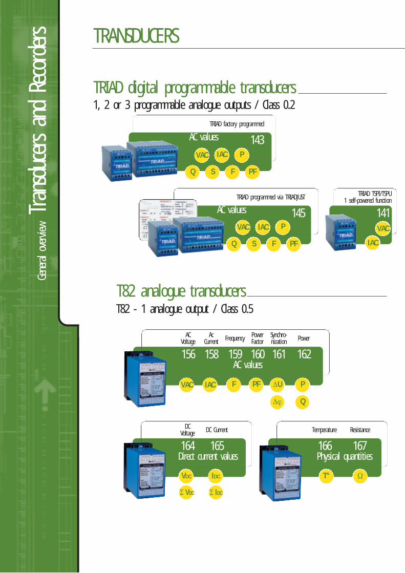
TRIAD digital programmable transducers
143
TRIAD factory programmed
141
TRIAD TSPI/TSPU1 self-powered function
T82 analogue transducers
156 158
ACVoltage
162
Ac Current
1, 2 or 3 programmable analogue outputs / Class 0.2
T82 - 1 analogue output / Class 0.5
IAC
Power
161
Synchro-nization
159
Frequency
160
PowerFactor
F PFVAC
Q
P∆U
∆ϕ
164 165
DCVoltage DC Current
IDCVDC
AC values
Direct current values167166
Resistance
Ω
Temperature
T°
Σ IDCΣ VDC
Physical quantities
IAC
F PF
VAC
Q
P
S
145
TRIAD programmed via TRIADJUST
IAC
VACIAC
F PF
VAC
Q
P
S
AC values
AC values
134136
SELECTION GUIDEINFO & ADVICE
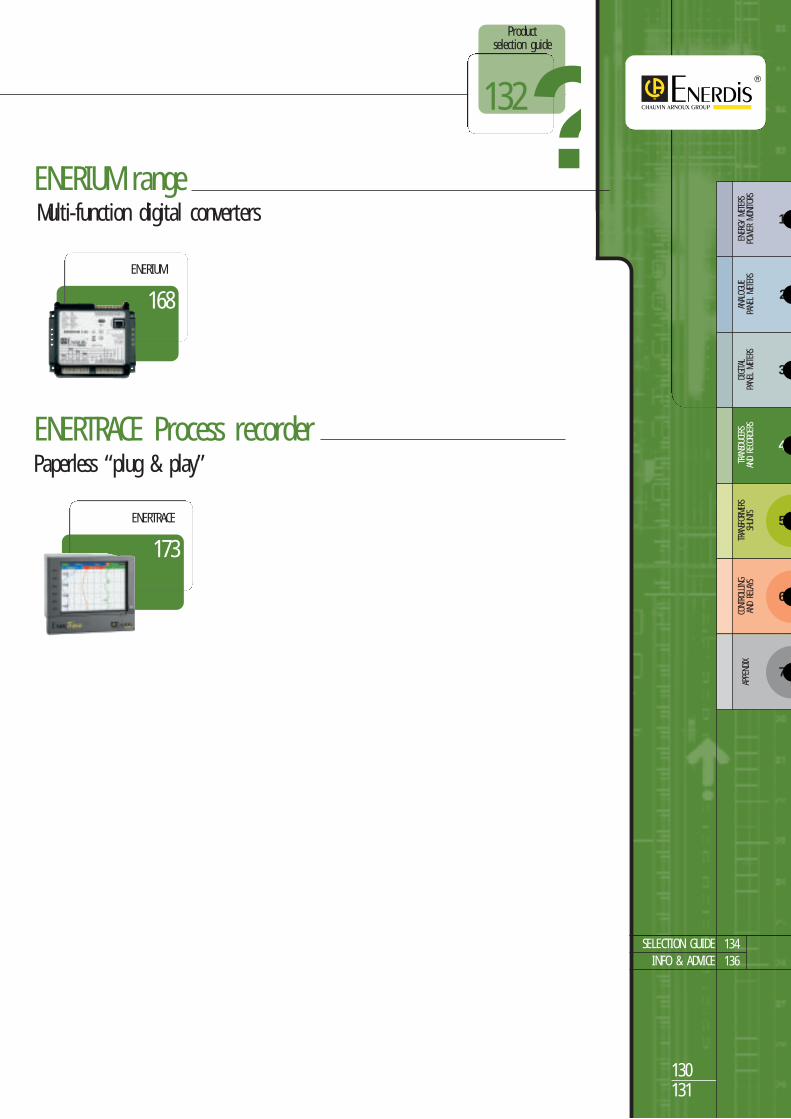
ENERIUM rangeMulti-function digital converters
Paperless “plug & play”ENERTRACE Process recorder
130131
173
ENERTRACE
Product selection guide
?132
3
4
5
6
ENER
GY M
ETER
S PO
WER
MON
ITORS
ANAL
OGUE
PA
NEL
METE
RSDIGITA
L PA
NEL
METE
RSTR
ANSD
UCER
SAN
D RE
CORD
ERS
TRAN
SFOR
MERS
SHUN
TSCO
NTRO
LLING
AND
RELA
YS
7
APPE
NDIX
2
1
168
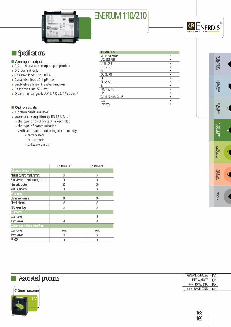
ENERIUM
Prod
uct selec
tion
guide
Tran
sducers an
d Re
corders SELECTING A DIGITAL TRANSDUCER
141
Self-powered
143
Factory-programmed
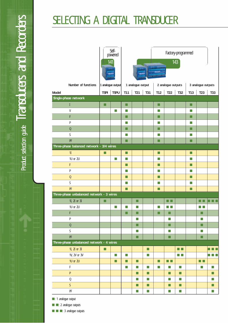
Number of functions 1 analogue output 1 analogue output 2 analogue outputs 3 analogue outputs
Model TSPI TSPU T11 T21 T31 T12 T22 T32 T13 T23 T33
Single-phase network
I
V
F
P
Q
S
PF
Three-phase balanced network - 3/4 wires
1I
1U or 2U
F
P
Q
S
PF
Three-phase unbalanced network - 3 wires
1I, 2I or 3I
1U or 2U
F
P
Q
S
PF
Three-phase unbalanced network - 4 wires
1I, 2I or 3I
1V, 2V or 3V
1U or 2U
F
P
Q
S
PF
: 1 analogue output
: 2 analogue outputs
: 3 analogue outputs
134136
INFO & ADVICERANGE INFO
132133
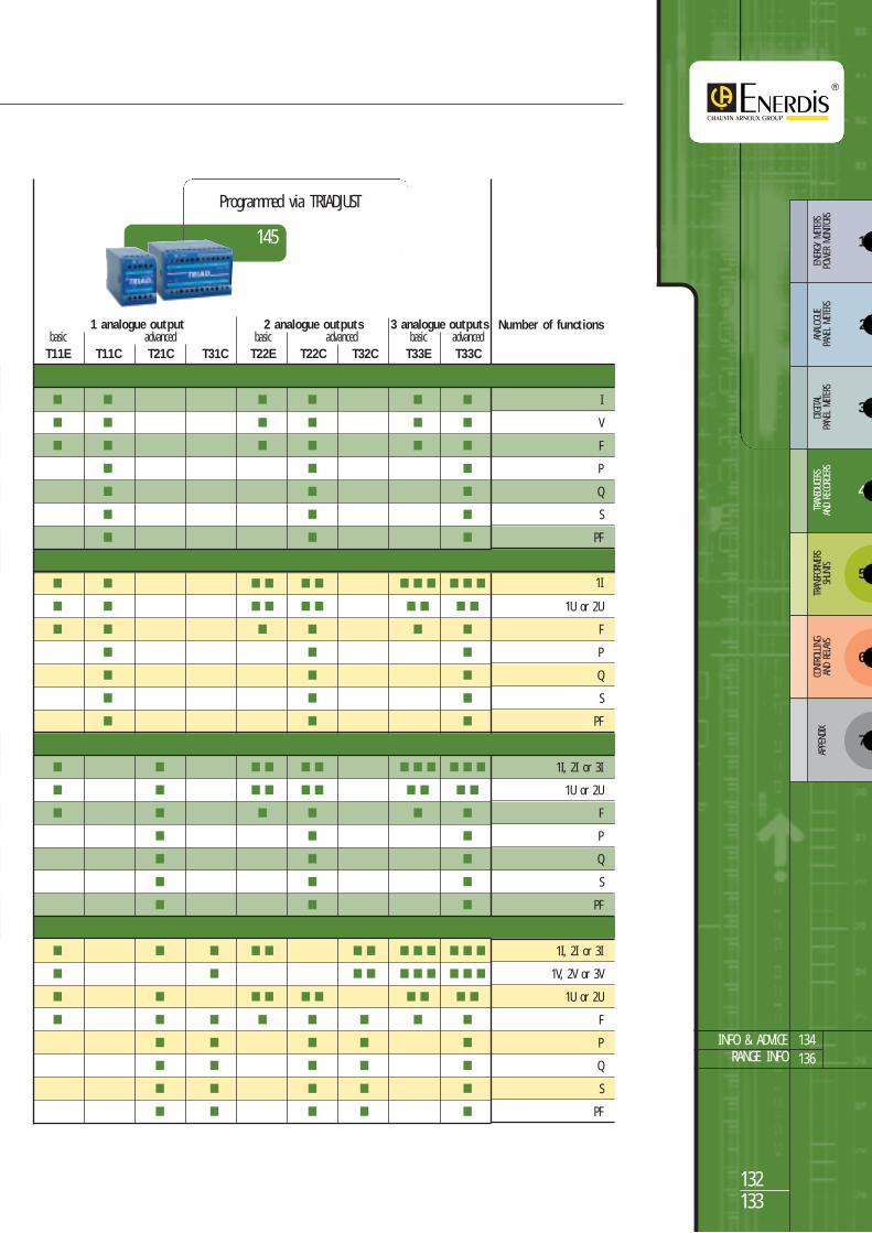
145
Programmed via TRIADJUST
Number of functions
I
V
F
P
Q
S
PF
1I
1U or 2U
F
P
Q
S
PF
1I, 2I or 3I
1U or 2U
F
P
Q
S
PF
1I, 2I or 3I
1V, 2V or 3V
1U or 2U
F
P
Q
S
PF
1 analogue output 2 analogue outputs 3 analogue outputsbasic advanced basic advanced basic advancedT11E T11C T21C T31C T22E T22C T32C T33E T33C
3
4
5
6
ENER
GY M
ETER
S PO
WER
MON
ITORS
ANAL
OGUE
PA
NEL
METE
RSDIGITA
L PA
NEL
METE
RSTR
ANSD
UCER
SAN
D RE
CORD
ERS
TRAN
SFOR
MERS
SHUN
TSCO
NTRO
LLING
AND
RELA
YS
7
APPE
NDIX
2
1

Info
& ad
viceTran
sducers an
d Re
corders
FACTORY-PROGRAMMEDOR USER-PROGRAMMABLE?
Transducers measure alternating current,direct current or physical quantities, andconvert them into a standard analogueDC signal (V or mA).
If the specifications of the measurementsto be carried out are known, afactory-programmed transducercan be used.
If the measurement specifications are notprecisely known, it is preferable to choose auser-programmable transducer.It can then be programmed by the userwhen the specifications are known and canbe modified if they change.
Factory-programmed User-programmable
KEEPING UP WITH CURR
WHICH TRANSFER CURVES SHOULD YOU CHOOSE?Linear Linear non-shifted Linear shifted
Linear 2 extended slopes Linear 2 slopes
Quadratic
132136
SELECTION GUIDERANGE INFO
134135
Universality: the nature of the output signal from the measurement transducer enablesquick and easy connection to a wide range of instruments (recorders, controllers, calculators,analogue and digital panel meters, measurement relays, PLCs, RTUs, etc.).
Response time: the response time of an analogue output enables real-time viewing ofall electrical parameters (for example, SCADA application, dispatching, control and monitoringof industrial processes).
Resistance to disturbances: analogue signals (current outputs in particular) are notsignificantly affected by electromagnetic disturbances. A single shielded pair wire enables youto transmit the output signal over very long distances (several hundred meters with out signalamplification).
Reliability: analogue transducer technology offers the advantage of several decades ofapplication and use, benefiting from wide experience in such varied fields as industry, thebuilding automation and electrical network supervision (dispatching).
Allows several functions to be assembled in one unit, contributing to a reduction in installationand cabling costs.
ADVANTAGES OF ANALOGUE OUTPUTS
ADVANTAGES OF PROGRAMMABLE TRANSDUCERS
ADVANTAGES OF TRANSDUCERWITH MULTIPLE ANALOGUE OUTPUTS
QUIZ3 questions to test your knowledge
Which of the following transducers has3 analogue outputs?
TRIAD T23
TRIAD T31C
C.A 3100
Which transducer range has the bestaccuracy class?
T82 range
ENERIUM range
TRIAD range
Which of these transducers is programmable?
TRIAD TSPU
TRIAD T32C
C.A 3100
To check your answers visit our site:www.enerdis.fr.
ENT CHANGES...
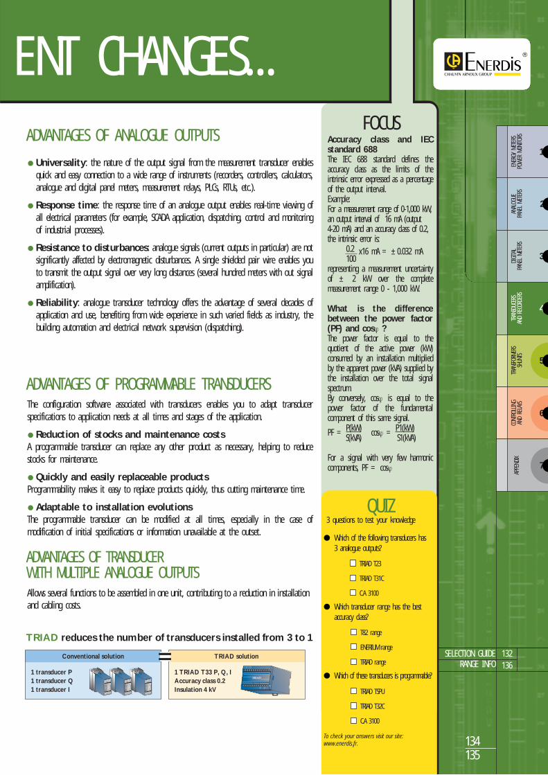
TRIAD reduces the number of transducers installed from 3 to 1
TRIAD solution
1 TRIAD T33 P, Q, IAccuracy class 0.2Insulation 4 kV
Conventional solution
1 transducer P1 transducer Q1 transducer I
8 9 10 11 12 13 14
5 6 7
1 2 3 4
TRANSDUCTEUR de MESURE
Classe de précision
Etendue de mesure
Courant nominal
Tension nominale
Sortie
Résistance de charge
Source auxiliaire
Schéma de branch.t
UAR 1210 B9520
0,5
0 - 132 V
50
0 - 10 mA
0 - 1
125 Vcc
2319501
A
V
V
Hz j :
N˚ de série N˚ d'identification
2318483 F
fabriqué en France
The configuration software associated with transducers enables you to adapt transducerspecifications to application needs at all times and stages of the application.
Reduction of stocks and maintenance costsA programmable transducer can replace any other product as necessary, helping to reducestocks for maintenance.
Quickly and easily replaceable productsProgrammability makes it easy to replace products quickly, thus cutting maintenance time.
Adaptable to installation evolutionsThe programmable transducer can be modified at all times, especially in the case ofmodification of initial specifications or information unavailable at the outset.
FOCUSAccuracy class and IECstandard 688The IEC 688 standard defines theaccuracy class as the limits of theintrinsic error expressed as a percentageof the output interval.Example:For a measurement range of 0-1,000 kW,an output interval of 16 mA (output4-20 mA) and an accuracy class of 0.2,the intrinsic error is:
0.2100
x16 mA = ±0.032 mA
representing a measurement uncertaintyof ± 2 kW over the completemeasurement range 0 - 1,000 kW.
What is the differencebetween the power factor(PF) and cosϕ ?The power factor is equal to thequotient of the active power (kW)consumed by an installation multipliedby the apparent power (kVA) supplied bythe installation over the total signalspectrum.By conversely, cosϕ is equal to thepower factor of the fundamentalcomponent of this same signal.
PF = P(kW) cosϕ = P1(kW)S(kVA) S1(kVA)
For a signal with very few harmoniccomponents, PF = cosϕ
3
4
5
6
ENER
GY M
ETER
S PO
WER
MON
ITORS
ANAL
OGUE
PA
NEL
METE
RSDIGITA
L PA
NEL
METE
RSTR
ANSD
UCER
SAN
D RE
CORD
ERS
TRAN
SFOR
MERS
SHUN
TSCO
NTRO
LLING
AND
RELA
YS
7
APPE
NDIX
2
1
Digit
al tec
hnolo
gy transdu
cersTran
sducers an
d Re
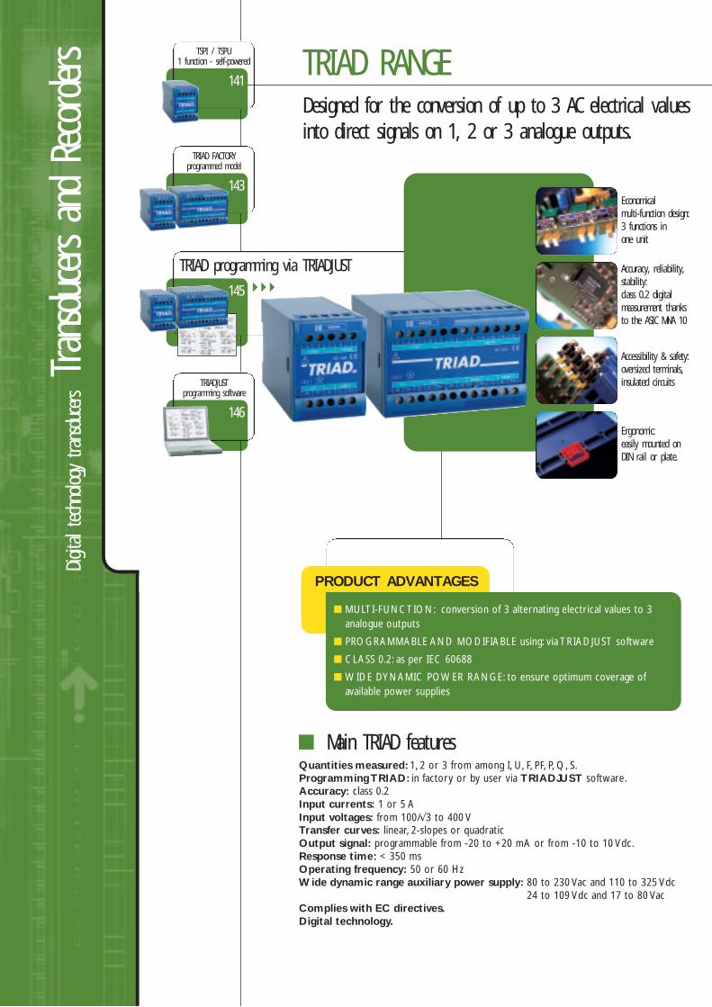
corders TRIAD RANGE
Designed for the conversion of up to 3 AC electrical valuesinto direct signals on 1, 2 or 3 analogue outputs.
Main TRIAD features
143
TRIAD FACTORYprogrammed model
145
TRIAD programming via TRIADJUST
141
TSPI / TSPU1 function - self-powered
146
TRIADJUSTprogramming software
PRODUCT ADVANTAGES
MULTI-FUNCTION: conversion of 3 alternating electrical values to 3analogue outputs
PROGRAMMABLE AND MODIFIABLE using: via TRIADJUST software
CLASS 0.2: as per IEC 60688
WIDE DYNAMIC POWER RANGE: to ensure optimum coverage ofavailable power supplies
Quantities measured: 1, 2 or 3 from among I, U, F, PF, P, Q, S.Programming TRIAD: in factory or by user via TRIADJUST software.Accuracy: class 0.2Input currents: 1 or 5 AInput voltages: from 100/√3 to 400 VTransfer curves: linear, 2-slopes or quadraticOutput signal: programmable from -20 to +20 mA or from -10 to 10 Vdc.Response time: < 350 msOperating frequency: 50 or 60 HzWide dynamic range auxiliary power supply: 80 to 230 Vac and 110 to 325 Vdc
24 to 109 Vdc and 17 to 80 VacComplies with EC directives.Digital technology.
Economicalmulti-function design:3 functions inone unit
Accuracy, reliability,stability:class 0.2 digitalmeasurement thanksto the ASIC MNA 10
Accessibility & safety:oversized terminals,insulated circuits
Ergonomic:easily mounted onDIN rail or plate.
Associated products
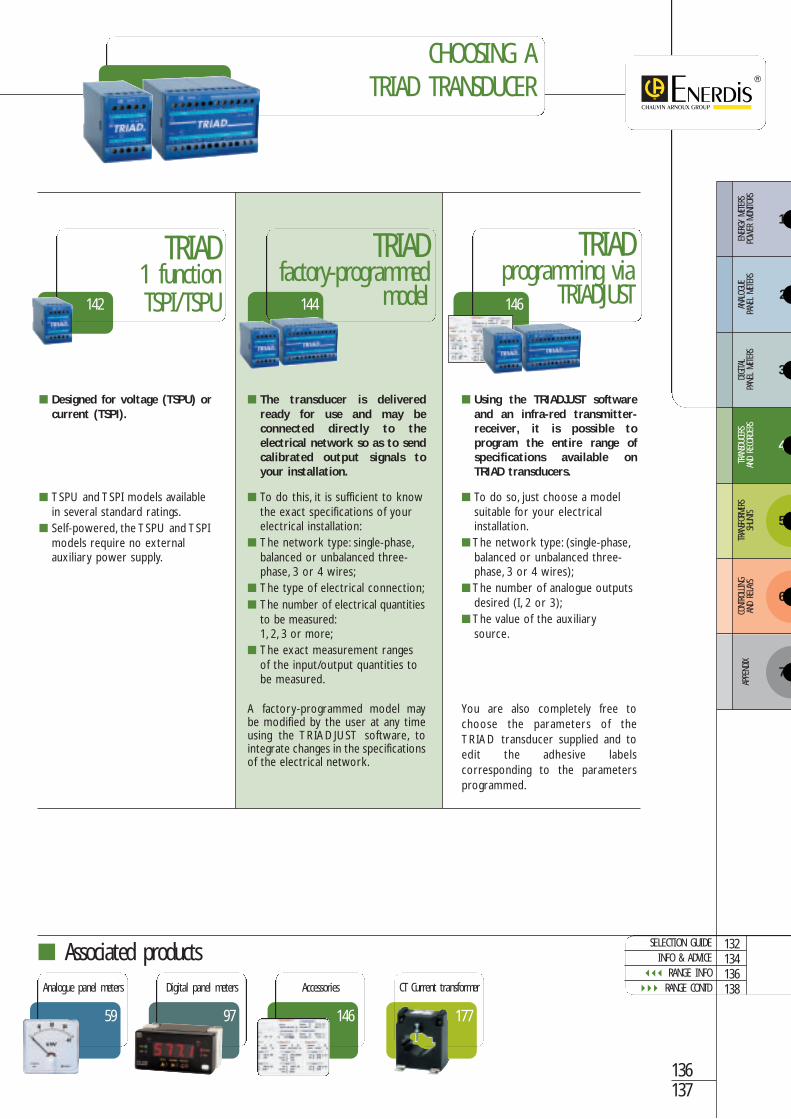
CHOOSING ATRIAD TRANSDUCER
TRIADfactory-programmed
model
TRIADprogramming via
TRIADJUST
TRIAD 1 functionTSPI/TSPU
To do this, it is sufficient to knowthe exact specifications of yourelectrical installation:
The network type: single-phase,balanced or unbalanced three-phase, 3 or 4 wires;
The type of electrical connection; The number of electrical quantities
to be measured:1, 2, 3 or more;
The exact measurement rangesof the input/output quantities tobe measured.
A factory-programmed model maybe modified by the user at any timeusing the TRIADJUST software, tointegrate changes in the specificationsof the electrical network.
The transducer is deliveredready for use and may beconnected directly to theelectrical network so as to sendcalibrated output signals toyour installation.
You are also completely free tochoose the parameters of theTRIAD transducer supplied and toedit the adhesive labelscorresponding to the parametersprogrammed.
To do so, just choose a modelsuitable for your electricalinstallation.
The network type: (single-phase,balanced or unbalanced three-phase, 3 or 4 wires);
The number of analogue outputsdesired (I, 2 or 3);
The value of the auxiliarysource.
Using the TRIADJUST softwareand an infra-red transmitter-receiver, it is possible toprogram the entire range ofspecifications available onTRIAD transducers.
TSPU and TSPI models availablein several standard ratings.
Self-powered, the TSPU and TSPImodels require no externalauxiliary power supply.
Designed for voltage (TSPU) orcurrent (TSPI).
144 146142
136137
146
Accessories
177
CT Current transformer
59
Analogue panel meters
97
Digital panel meters
SELECTION GUIDEINFO & ADVICE
RANGE INFO RANGE CONTD
132134136138
3
4
5
6
ENER
GY M
ETER
S PO
WER
MON
ITORS
ANAL
OGUE
PA
NEL
METE
RSDIGITA
L PA
NEL
METE
RSTR
ANSD
UCER
SAN
D RE
CORD
ERS
TRAN
SFOR
MERS
SHUN
TSCO
NTRO
LLING
AND
RELA
YS
7
APPE
NDIX
2
1
Digit
al tec
hnolo
gy transdu
cersTran
sducers an
d Re
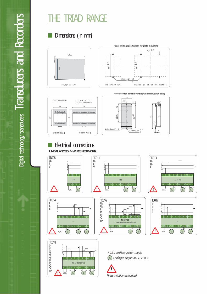
corders THE TRIAD RANGE
Dimensions (in mm)
Electrical connections
86
±0
.2
86
±0
.2
Panel drilling specification for plate mounting
T12, T13, T21, T22, T23, T31, T32 and T33T11, TSPU and TSPI
4 holes ø 4.5 0.20
70±0.2
T11, TSPI and TSPU
Weight: 320 g Weight: 700 g
120.5
or
or
or or
UNBALANCED 4-WIRE NETWORK
Phase rotation authorised
AUX.: auxiliary power supply
Analogue output no. 1, 2 or 3
TD008U12
FV
TD016U12
U32
FPT
QT
ST
FP
TD017V1
V2
V3
F
TD018I1I2I3V1
V2
V3
FPT
QT
ST
FP
TD011U12
FV
TD013U32
U12
F
TD014I1I2I3
20
4 chanfers 45° x 5 4 holes ø 4.5
R1
R2
0.20
40
86±0
.25
7610
2644
±0.2
96
5
Accessory for panel mounting with screws (optional)
T12, T13, T21, T22, T23, T31, T32 and T33
120
81
T11, TSPI and TSPU
60
81
w w w . e n e r d i s . f r
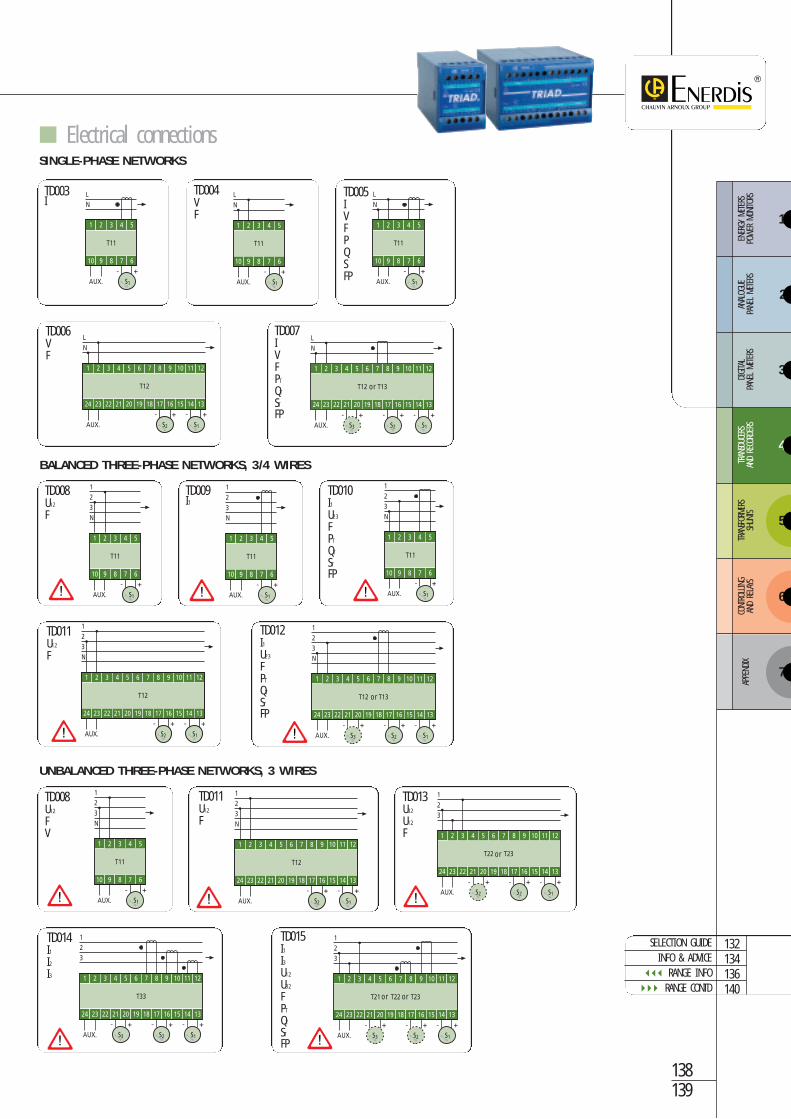
Electrical connections
or
or
or or
SINGLE-PHASE NETWORKS
BALANCED THREE-PHASE NETWORKS, 3/4 WIRES
UNBALANCED THREE-PHASE NETWORKS, 3 WIRES
or
TD003I
TD004VF
TD008U12
F
TD009I1
TD008U12
FV
TD005IVFPQSFP
TD006VF
TD007IVFPT
QT
ST
FP
TD010I1U23
FPT
QT
ST
FP
TD011U12
F
TD011U12
F
TD013U32
U12
F
TD014I1I2I3
TD015I1I3U12
U32
FPT
QT
ST
FP
TD012I1U23
FPT
QT
ST
FP
138139
SELECTION GUIDEINFO & ADVICE
RANGE INFO RANGE CONTD
132134136140
3
4
5
6
ENER
GY M
ETER
S PO
WER
MON
ITORS
ANAL
OGUE
PA
NEL
METE
RSDIGITA
L PA
NEL
METE
RSTR
ANSD
UCER
SAN
D RE
CORD
ERS
TRAN
SFOR
MERS
SHUN
TSCO
NTRO
LLING
AND
RELA
YS
7
APPE
NDIX
2
1
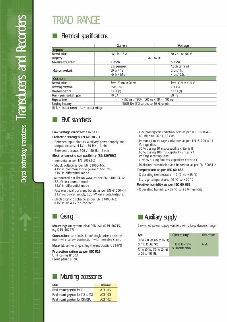
CasingMounting: on symmetrical DIN rail (DIN 60715,e.g DIN 46277)
Connection: terminals: 6mm2 single-wire or 4mm2
multi-wire screw connection with movable clamp
Material: self-extinguishing thermoplastic UL94VO
Protection rating as per IEC 529:Unit casing: IP 503 Front panel: IP 203
Digit
al tec
hnolo
gy transdu
cersTran
sducers an
d Re
corders TRIAD RANGE
Electrical specifications
EMC standards
Low voltage directive: 73/23/EECDielectric strength EN 61010 - 1- Between input circuits, auxiliary power supply and
output circuits: 4 kV – 50 Hz – 1min- Between outputs: 500 V - 50 Hz - 1 min Electromagnetic compatibility (89/336/EEC)- Immunity as per EN 50082-2- Shock voltage as per EN 61000-4-5:
4 kV in common mode (wave 1.2/50 ms),2 kV in differential mode
- Attenuated oscillation wave as per EN 61000-4-12:2.5 kV in common mode1 kV in differential mode
- Fast electrical transient bursts as per EN 61000-4-4:2 kV on power supply, 0.25 kV on inputs/outputs,
- Electrostatic discharge as per EN 61000-4-2:8 kV in air, 4 kV on contact
- Electromagnetic radiation field as per IEC 1000-4-3:80 MHz to 1GHz, 10 V/m
- Immunity to voltage variations as per EN 61000-4-11.Voltage dips:30 % during 10 ms, capability criteria B 60 % during 100 ms, capability criteria CVoltage interruptions:> 95 % during 500 ms, capability criteria C
- Radiation transmission and behaviour as per EN 50081-2Temperature as per IEC 60 688- Operating temperature: -10 °C to +55 °C- Storage temperature: -40 °C to +70 °CRelative humidity as per IEC 60 688- Operating humidity: +55 °C to 95 % humidity
Auxiliary supply2 switched power supply versions with a large dynamic range:
Type Operating range Consumption
80 to 230 Vac (45 to 65 Hz)or 110 to 325 Vdc +10 % to -15 % 6 VA
17 to 80 Vac (45 to 65 Hz) of extreme values
or 24 to 109 Vdc
Current VoltageInputs
Nominal value 1A In 5 A 50 V Un 480 VFrequency 45…65 HzMaximum consumption 0.5 VA 0.5 VA
2 In permanent 1.5 Un permanentMaximum overloads 20 In / 1 s 2 Un / 1 s
40 In / 0.5 s 4 Un / 0.5 sOutputs
Nominal value from -20 mA to 20 mA from -10 V to +10 VOperating resistance 15 V / Is (1) 1 kΩThreshold overruns 1.1 Is (1) 1.1 Us (1)Peak - peak residual ripple 40 µA 20 mVResponse time <350 ms / TSPU < 200 ms / TSPI < 100 msSampling frequency 15.625 kHz (312 samples per 50 Hz period)(1) Is = output current - Us = output voltage
Mounting accessoriesModel ReferencePanel mounting system for T11 ACCT 1007Panel mounting system for T12 to T33 ACCT 1006Panel mounting system for TSPI/TSPU ACCT 1007
w w w . e n e r d i s . f r
140141
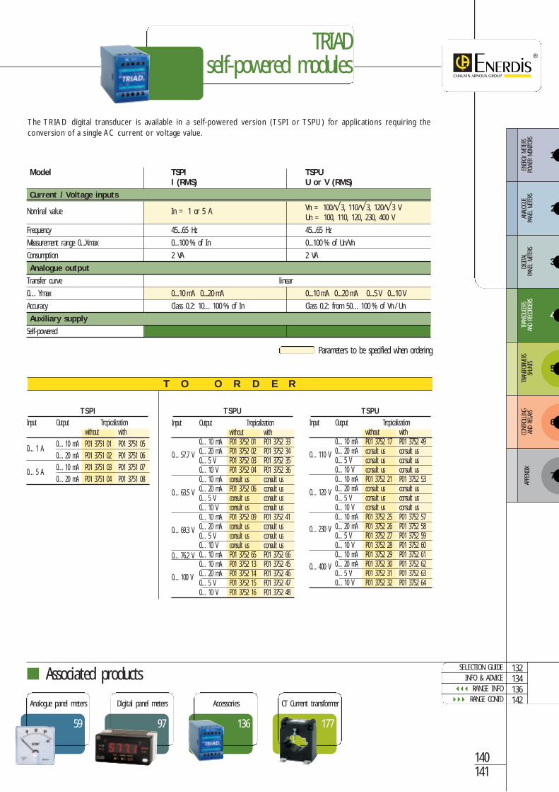
Input Output Tropicalizationwithout with
0…10 mA P01 3752 17 P01 3752 49
0…110 V 0…20 mA consult us consult us0…5 V consult us consult us0…10 V consult us consult us0…10 mA P01 3752 21 P01 3752 53
0…120 V 0…20 mA consult us consult us0…5 V consult us consult us0…10 V consult us consult us0…10 mA P01 3752 25 P01 3752 57
0…230 V 0…20 mA P01 3752 26 P01 3752 580…5 V P01 3752 27 P01 3752 590…10 V P01 3752 28 P01 3752 600…10 mA P01 3752 29 P01 3752 61
0…400 V 0…20 mA P01 3752 30 P01 3752 620…5 V P01 3752 31 P01 3752 630…10 V P01 3752 32 P01 3752 64
TRIAD self-powered modules
Associated products
Input Output Tropicalizationwithout with
0…1 A 0…10 mA P01 3751 01 P01 3751 050…20 mA P01 3751 02 P01 3751 06
0…5 A 0…10 mA P01 3751 03 P01 3751 070…20 mA P01 3751 04 P01 3751 08
Input Output Tropicalizationwithout with
0…10 mA P01 3752 01 P01 3752 33
0…57.7 V 0…20 mA P01 3752 02 P01 3752 340…5 V P01 3752 03 P01 3752 350…10 V P01 3752 04 P01 3752 360…10 mA consult us consult us
0…63.5 V 0…20 mA P01 3752 06 consult us0…5 V consult us consult us0…10 V consult us consult us0…10 mA P01 3752 09 P01 3752 41
0…69.3 V 0…20 mA consult us consult us0…5 V consult us consult us0…10 V consult us consult us
0…76.2 V 0…10 mA P01 3752 65 P01 3752 660…10 mA P01 3752 13 P01 3752 45
0…100 V 0…20 mA P01 3752 14 P01 3752 460…5 V P01 3752 15 P01 3752 470…10 V P01 3752 16 P01 3752 48
177
CT Current transformer
136
Accessories
59
Analogue panel meters
97
Digital panel meters
The TRIAD digital transducer is available in a self-powered version (TSPI or TSPU) for applications requiring theconversion of a single AC current or voltage value.
T O O R D E R
Parameters to be specified when ordering
Model TSPI TSPUI (RMS) U or V (RMS)
Current / Voltage inputs
Nominal value In = 1 or 5 A Vn = 100/√3, 110/√3, 120/√3 VUn = 100, 110, 120, 230, 400 V
Frequency 45...65 Hz 45...65 Hz
Measurement range 0...Xmax 0...100 % of In 0...100 % of Un/Vn
Consumption 2 VA 2 VA
Analogue output
Transfer curve linear
0…Ymax 0...10 mA 0...20 mA 0...10 mA 0...20 mA 0...5 V 0...10 V
Accuracy Class 0.2: 10…100 % of In Class 0.2: from 50…100 % of Vn / Un
Auxiliary supply
Self-powered
TSPI TSPU TSPU
SELECTION GUIDEINFO & ADVICE
RANGE INFO RANGE CONTD
132134136142
3
4
5
6
ENER
GY M
ETER
S PO
WER
MON
ITORS
ANAL
OGUE
PA
NEL
METE
RSDIGITA
L PA
NEL
METE
RSTR
ANSD
UCER
SAN
D RE
CORD
ERS
TRAN
SFOR
MERS
SHUN
TSCO
NTRO
LLING
AND
RELA
YS
7
APPE
NDIX
2
1
Single-phase
Three-phase balanced 3/4 wires
Three-phase unbalanced 3 wires
Three-phase unbalanced 4 wires
Digit
al tec
hnolo
gy transdu
cersTran
sducers an
d Re
corders
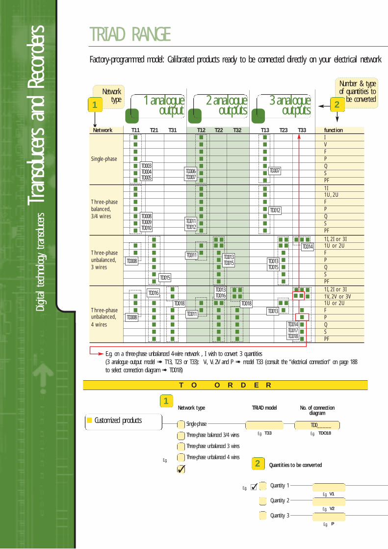
Quantities to be converted
TRIAD RANGE
Network type TRIAD model No. of connectiondiagram
E.g. on a three-phase unbalanced 4-wire network , I wish to convert 3 quantities(3 analogue output model T13, T23 or T33): V1, V2, 2V and P model T33 (consult the “electrical connection” on page 188to select connection diagram TD018)
Network T11 T21 T31 T12 T22 T32 T13 T23 T33 function I V F
Single-phase P Q S PF 1I 1U, 2U
Three-phase Fbalanced, P3/4 wires Q
S PF
1I, 2I or 3I 1U or 2U
Three-phase Funbalanced, P3 wires Q
S PF
1I, 2I or 3I 1V, 2V or 3V 1U or 2U
Three-phase Funbalanced, P4 wires Q
S PF
T O O R D E R
1 analogueoutput
2 analogueoutputs
3 analogueoutputs
Networktype
1
Number & typeof quantities to
be converted2
TD003TD004TD005
TD006TD007
TD008TD009TD010
TD015
TD016
TD018
TD011
TD011 TD013TD015 TD013
TD015
TD014
TD014TD017TD018
TD013
TD013TD016
TD018
TD011TD012
TD012
TD007
TD008
TD008
1
2
TD0_____
Factory-programmed model: Calibrated products ready to be connected directly on your electrical network
E.g.
E.g. T33
E.g. V1
E.g. V2
E.g. P
E.g. TDO18
Quantity 1
Quantity 2
Quantity 3
Customized products
E.g.
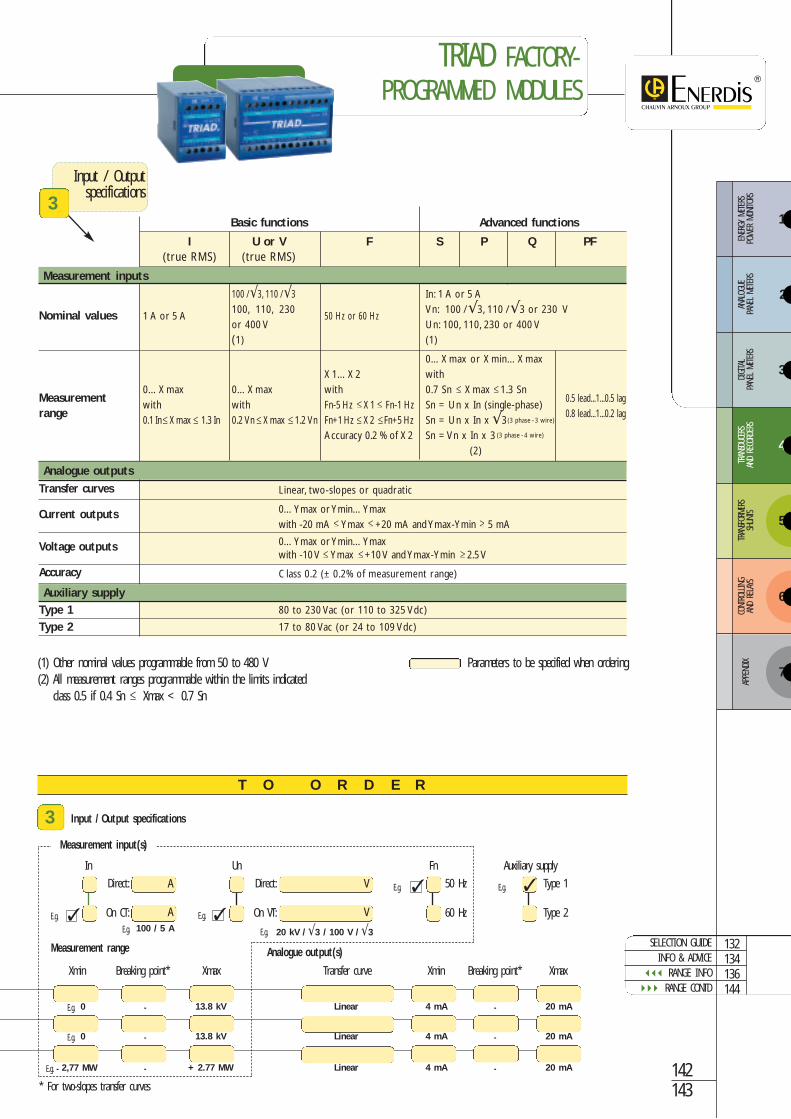
Measurement range Analogue output(s)
Measurement input(s)
T O O R D E R
(1) Other nominal values programmable from 50 to 480 V(2) All measurement ranges programmable within the limits indicated
class 0.5 if 0.4 Sn Xmax < 0.7 Sn
Direct:
On CT:
Direct:
On VT:
In Un
Xmin Breaking point* Xmax Transfer curve Xmin Breaking point* Xmax
Input / Outputspecifications
3
Parameters to be specified when ordering
Input / Output specifications3
A
A
V
V
142143
50 Hz
60 Hz
Fn
Type 1
Type 2
Auxiliary supply
E.g. 100 / 5 A E.g. 20 kV / √3 / 100 V / √3
E.g. 0
E.g. 0
E.g. - 2,77 MW
-
-
-
-
-
-
13.8 kV
13.8 kV
+ 2.77 MW
4 mA
4 mA
4 mA
20 mA
20 mA
20 mA
Linear
Linear
Linear
* For two-slopes transfer curves
Basic functions Advanced functions
I U or V F S P Q PF(true RMS) (true RMS)
Measurement inputs
100 /√3, 110 /√3 In: 1 A or 5 A
Nominal values 1 A or 5 A100, 110, 230
50 Hz or 60 HzVn: 100 /√3, 110 /√3 or 230 V
or 400 V Un: 100, 110, 230 or 400 V(1) (1)
0…Xmax or Xmin…Xmax X1…X2 with
0…Xmax 0…Xmax with 0.7 Sn Xmax 1.3 SnMeasurement
with with Fn-5 Hz X1 Fn-1 Hz Sn = Un x In (single-phase)0.5 lead...1...0.5 lag
range0.1 In Xmax 1.3 In 0.2 Vn Xmax 1.2 Vn Fn+1Hz X2 Fn+5 Hz Sn = Un x In x √3
0.8 lead...1...0.2 lag
Accuracy 0.2 % of X2 Sn = Vn x In x 3 (2)
Analogue outputs
Transfer curves Linear, two-slopes or quadratic
Current outputs 0…Ymax or Ymin…Ymaxwith -20 mA Ymax +20 mA and Ymax-Ymin 5 mA
Voltage outputs 0…Ymax or Ymin…Ymaxwith -10 V Ymax +10 V and Ymax-Ymin 2.5 V
Accuracy Class 0.2 (± 0.2% of measurement range)
Auxiliary supplyType 1 80 to 230 Vac (or 110 to 325 Vdc)
Type 2 17 to 80 Vac (or 24 to 109 Vdc)
SELECTION GUIDEINFO & ADVICE
RANGE INFO RANGE CONTD
132134136144
E.g. E.g.
E.g. E.g.
TRIAD FACTORY-PROGRAMMED MODULES
3
4
5
6
ENER
GY M
ETER
S PO
WER
MON
ITORS
ANAL
OGUE
PA
NEL
METE
RSDIGITA
L PA
NEL
METE
RSTR
ANSD
UCER
SAN
D RE
CORD
ERS
TRAN
SFOR
MERS
SHUN
TSCO
NTRO
LLING
AND
RELA
YS
7
APPE
NDIX
2
1
(3 phase - 3 wire)
(3 phase - 4 wire)
Digit
al tec
hnolo
gy transdu
cersTran
sducers an
d Re
corders TRIAD RANGE
Associated products
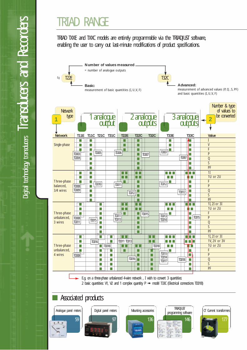
E.g. on a three-phase unbalanced 4-wire network , I wish to convert 3 quantities:2 basic quantities: V1, V2 and 1 complex quantity P model T33C (Electrical connections TD018)
Network T11E T11C T21C T31C T22E T22C T32C T33E T33C Value I
Single-phase V F
P Q S PF
1I 1U or 2U
Three-phase Fbalanced, P3/4 wires Q
S PF
1I, 2I or 3I 1U or 2U
Three-phase Funbalanced, P3 wires Q
S PF
1I, 2I or 3I 1V, 2V or 3V
Three-phase 1U or 2Uunbalanced, F4 wires P
Q S PF
Networktype
T22E T32C
1
Number & typeof values to be converted
2
177
CT Current transformers
59
Analogue panel meters
97
Digital panel meters
136
Mounting accessories
1 analogueoutput
2 analogueoutputs
3 analogueoutputs
TD003TD004
TD005 TD006 TD007TD007
TD007
TD010 TD011
TD012
TD012
TD012
TD015
TD015TD015
TD016
TD016
TD011 TD013TD018 TD018
TD018
TD008TD009
TD008TD011
TD011TD013
TD013TD014TD017
TD013TD014
TD008
TRIAD TXXE and TXXC models are entirely programmable via the TRIADJUST software,enabling the user to carry out last-minute modifications of product specifications.
Number of values measured= number of analogue outputs
Basic:measurement of basic quantities (I, U,V, F)
Advanced:measurement of advanced values (P, Q, S, PF)and basic quantities (I, U,V, F)
E.g
146
TRIADJUSTprogramming software
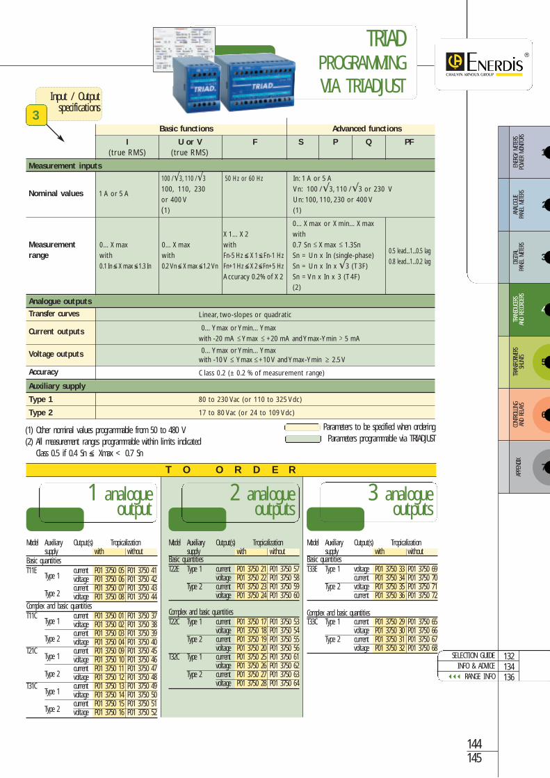
Model Auxiliary Output(s) Tropicalizationsupply with without
Basic quantitiesT11E
Type 1current P01 3750 05 P01 3750 41voltage P01 3750 06 P01 3750 42
Type 2current P01 3750 07 P01 3750 43voltage P01 3750 08 P01 3750 44
Complex and basic quantitiesT11C
Type 1current P01 3750 01 P01 3750 37voltage P01 3750 02 P01 3750 38
Type 2current P01 3750 03 P01 3750 39voltage P01 3750 04 P01 3750 40
T21CType 1
current P01 3750 09 P01 3750 45voltage P01 3750 10 P01 3750 46
Type 2current P01 3750 11 P01 3750 47voltage P01 3750 12 P01 3750 48
T31CType 1
current P01 3750 13 P01 3750 49voltage P01 3750 14 P01 3750 50
Type 2current P01 3750 15 P01 3750 51voltage P01 3750 16 P01 3750 52
Model Auxiliary Output(s) Tropicalizationsupply with without
Basic quantitiesT22E Type 1 current P01 3750 21 P01 3750 57
voltage P01 3750 22 P01 3750 58Type 2 current P01 3750 23 P01 3750 59
voltage P01 3750 24 P01 3750 60
Complex and basic quantitiesT22C Type 1 current P01 3750 17 P01 3750 53
voltage P01 3750 18 P01 3750 54Type 2 current P01 3750 19 P01 3750 55
voltage P01 3750 20 P01 3750 56T32C Type 1 current P01 3750 25 P01 3750 61
voltage P01 3750 26 P01 3750 62Type 2 current P01 3750 27 P01 3750 63
voltage P01 3750 28 P01 3750 64
Model Auxiliary Output(s) Tropicalizationsupply with without
Basic quantitiesT33E Type 1 voltage P01 3750 33 P01 3750 69
current P01 3750 34 P01 3750 70Type 2 voltage P01 3750 35 P01 3750 71
current P01 3750 36 P01 3750 72
Complex and basic quantities T33C Type 1 current P01 3750 29 P01 3750 65
voltage P01 3750 30 P01 3750 66Type 2 current P01 3750 31 P01 3750 67
voltage P01 3750 32 P01 3750 68
1 analogueoutput
2 analogueoutputs
3 analogueoutputs
132134136
SELECTION GUIDEINFO & ADVICE
RANGE INFO
T O O R D E R
144145
(1) Other nominal values programmable from 50 to 480 V(2) All measurement ranges programmable within limits indicated
Class 0.5 if 0.4 Sn ≤ Xmax < 0.7 Sn
Input / Outputspecifications
3Basic functions Advanced functions
I U or V F S P Q PF(true RMS) (true RMS)
Measurement inputs
100 /√3, 110 /√3 50 Hz or 60 Hz In: 1 A or 5 A
Nominal values 1 A or 5 A100, 110, 230 Vn: 100 /√3, 110 /√3 or 230 Vor 400 V Un: 100, 110, 230 or 400 V(1) (1)
0…Xmax or Xmin…Xmax X1…X2 with
Measurement 0…Xmax 0…Xmax with 0.7 Sn Xmax 1.3Snrange with with Fn-5 Hz ≤ X1 ≤Fn-1 Hz Sn = Un x In (single-phase)
0.5 lead...1...0.5 lag
0.1 In≤ Xmax≤1.3 In 0.2Vn≤ Xmax≤1.2Vn Fn+1Hz≤ X2≤Fn+5 Hz Sn = Un x In x √3 (T3F)0.8 lead...1...0.2 lag
Accuracy 0.2% of X2 Sn = Vn x In x 3 (T4F)(2)
Analogue outputs
Transfer curves Linear, two-slopes or quadratic
Current outputs 0…Ymax or Ymin…Ymaxwith -20 mA Ymax +20 mA and Ymax-Ymin 5 mA
Voltage outputs 0…Ymax or Ymin…Ymaxwith -10 V Ymax +10 V and Ymax-Ymin 2.5 V
Accuracy Class 0.2 (± 0.2 % of measurement range)
Auxiliary supply
Type 1 80 to 230 Vac (or 110 to 325 Vdc)
Type 2 17 to 80 Vac (or 24 to 109 Vdc)
Parameters to be specified when orderingParameters programmable via TRIADJUST
TRIADPROGRAMMINGVIA TRIADJUST
3
4
5
6
ENER
GY M
ETER
S PO
WER
MON
ITORS
ANAL
OGUE
PA
NEL
METE
RSDIGITA
L PA
NEL
METE
RSTR
ANSD
UCER
SAN
D RE
CORD
ERS
TRAN
SFOR
MERS
SHUN
TSCO
NTRO
LLING
AND
RELA
YS
7
APPE
NDIX
2
1
Digit
al tec
hnolo
gy transdu
cersTran
sducers an
d Re
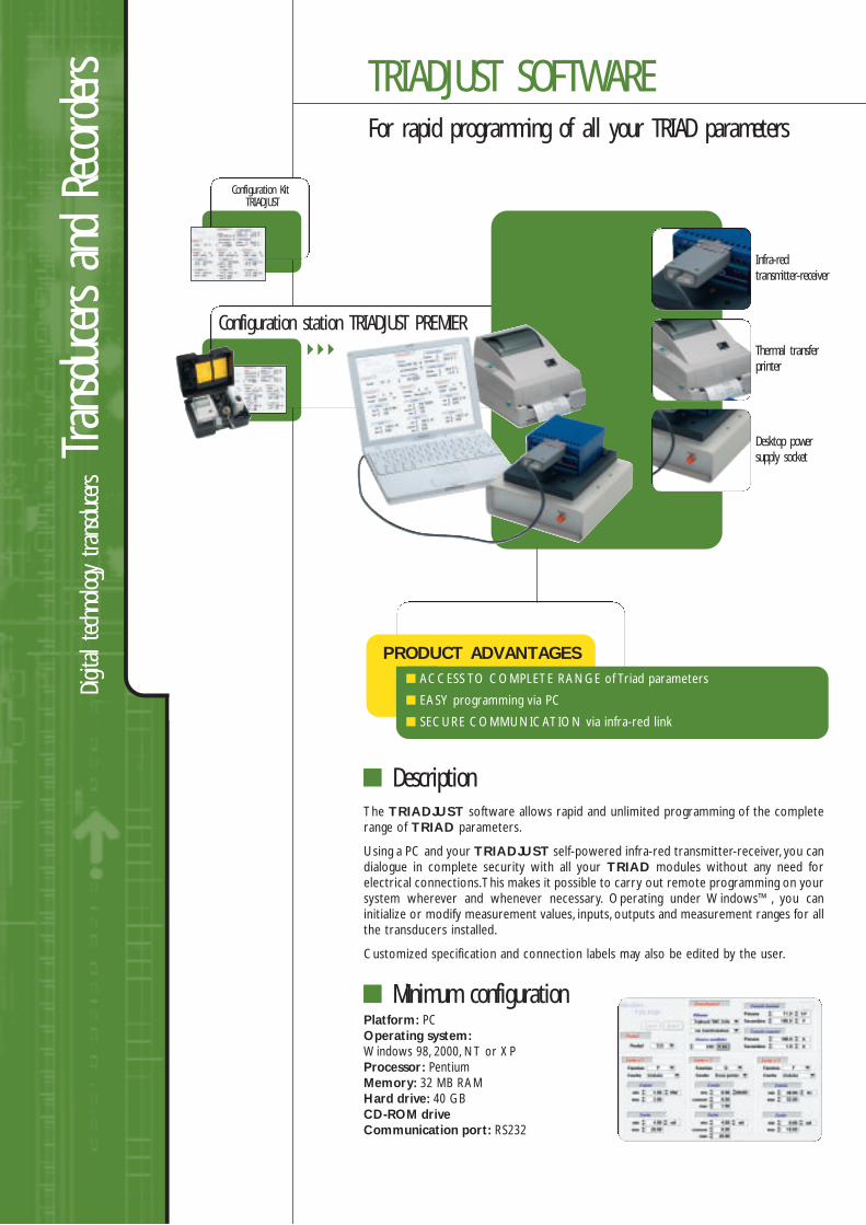
corders TRIADJUST SOFTWARE
For rapid programming of all your TRIAD parameters
Description
Configuration KitTRIADJUST
Configuration station TRIADJUST PREMIER
PRODUCT ADVANTAGES ACCESS TO COMPLETE RANGE of Triad parameters
EASY programming via PC
SECURE COMMUNICATION via infra-red link
The TRIADJUST software allows rapid and unlimited programming of the completerange of TRIAD parameters.
Using a PC and your TRIADJUST self-powered infra-red transmitter-receiver, you candialogue in complete security with all your TRIAD modules without any need forelectrical connections.This makes it possible to carry out remote programming on yoursystem wherever and whenever necessary. Operating under Windows™, you caninitialize or modify measurement values, inputs, outputs and measurement ranges for allthe transducers installed.
Customized specification and connection labels may also be edited by the user.
Platform: PC Operating system:Windows 98, 2000, NT or XPProcessor: PentiumMemory: 32 MB RAMHard drive: 40 GBCD-ROM driveCommunication port: RS232
Infra-redtransmitter-receiver
Thermal transferprinter
Desktop powersupply socket
Minimum configuration
132134146
SELECTION GUIDEINFO & ADVICE
RANGE INFO
145
TRIAD programmingvia TRIADJUST
Associated products
Model ReferenceTRIADJUST Kit TAJT 2000AccessoriesSet of 30 labels + marker ACCT 1008Infra-red transmitter / receiver PO1 3759 02A
Model ReferenceTRIADJUST PREMIER module TADJ 1000AccessoriesSet of 1,500 labels + ribbon ACCT 1005Infra-red transmitter / receiver PO1 3759 02A
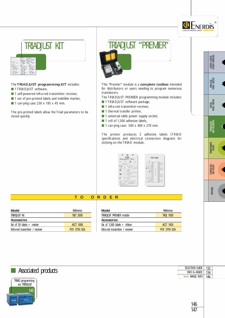
This "Premier" module is a complete toolbox intendedfor distributors or users needing to program numeroustransducers.The TRIADJUST PREMIER programming module includes: 1 TRIADJUST software package, 1 infra-red transmitter-receiver, 1 thermal transfer printer, 1 universal table power supply socket, 1 roll of 1,500 adhesive labels, 1 carrying case: 500 x 400 x 270 mm.
The printer produces 2 adhesive labels (TRIADspecifications and electrical connection diagram) forsticking on the TRIAD module.
The TRIADJUST programming KIT includes: 1 TRIADJUST software, 1 self-powered infra-red transmitter receiver, 1 set of pre-printed labels and indelible marker, 1 carrying case: 230 x 185 x 45 mm.
The pre-printed labels allow the Triad parameters to benoted quickly.
146147
TRIADJUST “PREMIER”TRIADJUST KIT
T O O R D E R
TD 015
3
4
5
6
ENER
GY M
ETER
S PO
WER
MON
ITORS
ANAL
OGUE
PA
NEL
METE
RSDIGITA
L PA
NEL
METE
RSTR
ANSD
UCER
SAN
D RE
CORD
ERS
TRAN
SFOR
MERS
SHUN
TSCO
NTRO
LLING
AND
RELA
YS
7
APPE
NDIX
2
1

Analo
gue
techn
ology transdu
cersTran
sducers an
d Re
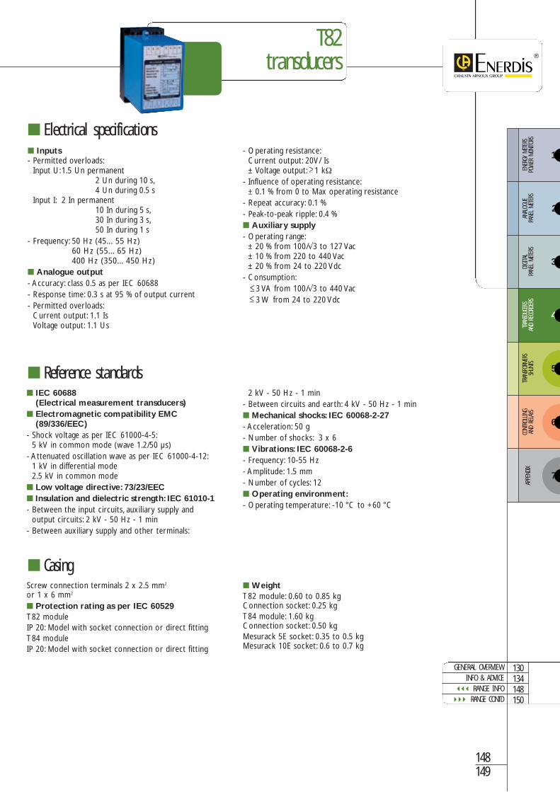
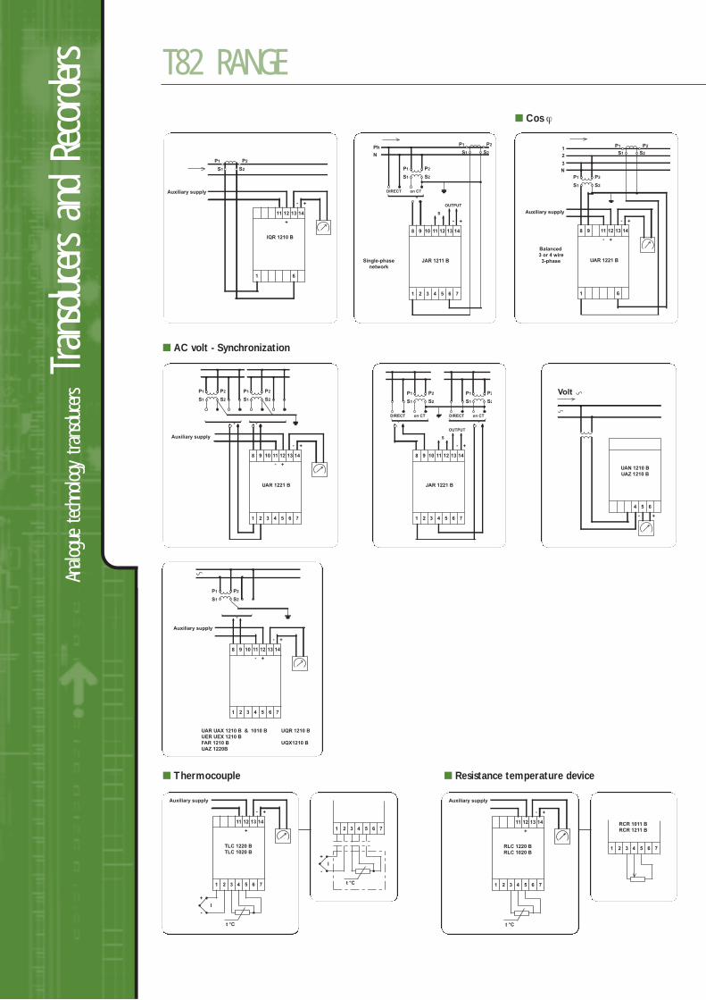
corders T82 RANGE
Analogue transducers for AC/DC electrical quantities orphysical quantities, class 0.5
The T82 range of transducers measures AC/DC electrical quantities and physicalquantities and converts them into a standard low-level direct signal (current or voltage)(for example: 4...20 mA).
They are normally used in conjunction with analogue or digital measuring instruments(panel meters, recorders, etc.), supervision equipment (PLCs, SCADA and building management automation systems) and are also incorporated in control andmeasurement loops.
Plug-in version withspecial socket forplate mounting orDIN rail mounting
Rack version for19" - 3U:model suppliedrack-mounted orseparately, comeswith connections
Description
AC Voltage 156
AC Current 158
Power 162
Synchronization 161
Frequency 159
Phase angle 160
AC values
DC values
PRODUCT ADVANTAGES
AVAILABLE IN 3 VERSIONS: plate mounting, plug-in or rack
ON-DEMAND PROGRAMMING: input/output quantities, transfer curve, etc.
WIDE RANGE OF MEASURABLE QUANTITIES: AC/DC electricalquantities and physical quantities
IAC
F
PF
VAC
P
DC VoltageSummation 164
DC CurrentSummation 165 IDC
VDC
Resistance 166
Temperature 167
Physical values
T°
Ω
Q
∆U ∆ϕ
Σ IDC
Σ VDC
T82transducers
148149
Screw connection terminals 2 x 2.5 mm2
or 1 x 6 mm2
Protection rating as per IEC 60529T82 moduleIP 20: Model with socket connection or direct fittingT84 moduleIP 20: Model with socket connection or direct fitting
WeightT82 module: 0.60 to 0.85 kgConnection socket: 0.25 kgT84 module: 1.60 kgConnection socket: 0.50 kgMesurack 5E socket: 0.35 to 0.5 kgMesurack 10E socket: 0.6 to 0.7 kg
Inputs- Permitted overloads:
Input U:1.5 Un permanent2 Un during 10 s,4 Un during 0.5 s
Input I: 2 In permanent10 In during 5 s,30 In during 3 s,50 In during 1 s
- Frequency: 50 Hz (45…55 Hz)60 Hz (55…65 Hz)400 Hz (350…450 Hz)
Analogue output- Accuracy: class 0.5 as per IEC 60688- Response time: 0.3 s at 95 % of output current- Permitted overloads:
Current output: 1.1 IsVoltage output: 1.1 Us
- Operating resistance:Current output: 20V/ Is± Voltage output: 1 kΩ
- Influence of operating resistance:± 0.1 % from 0 to Max operating resistance
- Repeat accuracy: 0.1 %- Peak-to-peak ripple: 0.4 % Auxiliary supply- Operating range:
± 20 % from 100/√3 to 127 Vac± 10 % from 220 to 440 Vac± 20 % from 24 to 220 Vdc
- Consumption:3 VA from 100/√3 to 440 Vac3 W from 24 to 220 Vdc
Electrical specifications
Reference standards
Casing
IEC 60688(Electrical measurement transducers)
Electromagnetic compatibility EMC(89/336/EEC)
- Shock voltage as per IEC 61000-4-5:5 kV in common mode (wave 1.2/50 µs)
- Attenuated oscillation wave as per IEC 61000-4-12:1 kV in differential mode 2.5 kV in common mode
Low voltage directive: 73/23/EEC Insulation and dielectric strength: IEC 61010-1- Between the input circuits, auxiliary supply and
output circuits: 2 kV - 50 Hz - 1 min- Between auxiliary supply and other terminals:
2 kV - 50 Hz - 1 min- Between circuits and earth: 4 kV - 50 Hz - 1 min Mechanical shocks: IEC 60068-2-27- Acceleration: 50 g- Number of shocks: 3 x 6 Vibrations: IEC 60068-2-6- Frequency: 10-55 Hz- Amplitude: 1.5 mm- Number of cycles: 12 Operating environment:- Operating temperature: -10 °C to +60 °C
GENERAL OVERVIEWINFO & ADVICE
RANGE INFO RANGE CONTD
130134148150
3
4
5
6
ENER
GY M
ETER
S PO
WER
MON
ITORS
ANAL
OGUE
PA
NEL
METE
RSDIGITA
L PA
NEL
METE
RSTR
ANSD
UCER
SAN
D RE
CORD
ERS
TRAN
SFOR
MERS
SHUN
TSCO
NTRO
LLING
AND
RELA
YS
7
APPE
NDIX
2
1

Analo
gue
techn
ology transdu
cersTran
sducers an
d Re
corders T82 RANGE
Dimensions (in mm)T82 plate mounting module
T82 plug-in module
T82 rack
19” - 3U rack
2 screws
450 Sealable screws option
466 basic
150151
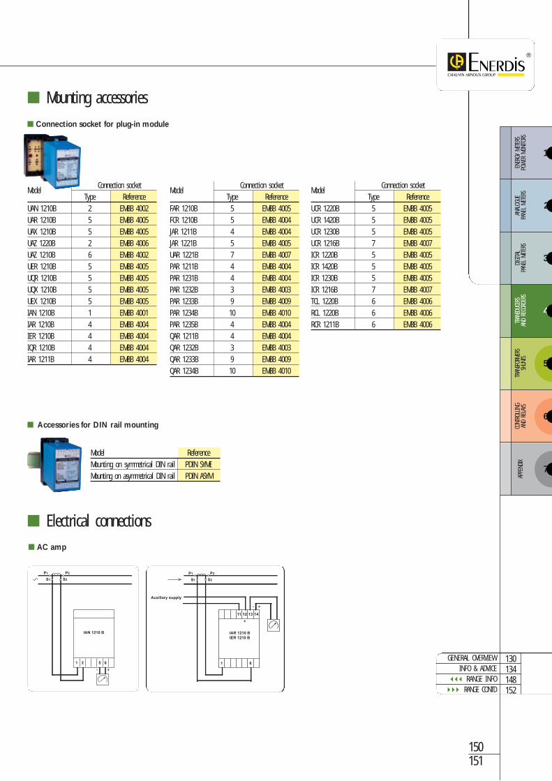
Mounting accessories
Electrical connections
Connection socketModel
Type ReferenceUAN 1210B 2 EMBB 4002UAR 1210B 5 EMBB 4005UAX 1210B 5 EMBB 4005UAZ 1220B 2 EMBB 4006UAZ 1210B 6 EMBB 4002UER 1210B 5 EMBB 4005UQR 1210B 5 EMBB 4005UQX 1210B 5 EMBB 4005UEX 1210B 5 EMBB 4005IAN 1210B 1 EMBB 4001IAR 1210B 4 EMBB 4004IER 1210B 4 EMBB 4004IQR 1210B 4 EMBB 4004IAR 1211B 4 EMBB 4004
Connection socket for plug-in module
Model ReferenceMounting on symmetrical DIN rail PDIN SYMEMounting on asymmetrical DIN rail PDIN ASYM
Accessories for DIN rail mounting
Connection socketModel
Type ReferenceFAR 1210B 5 EMBB 4005FCR 1210B 5 EMBB 4004JAR 1211B 4 EMBB 4004JAR 1221B 5 EMBB 4005UAR 1221B 7 EMBB 4007PAR 1211B 4 EMBB 4004PAR 1231B 4 EMBB 4004PAR 1232B 3 EMBB 4003PAR 1233B 9 EMBB 4009PAR 1234B 10 EMBB 4010PAR 1235B 4 EMBB 4004QAR 1211B 4 EMBB 4004QAR 1232B 3 EMBB 4003QAR 1233B 9 EMBB 4009QAR 1234B 10 EMBB 4010
Connection socketModel
Type ReferenceUCR 1220B 5 EMBB 4005UCR 1420B 5 EMBB 4005UCR 1230B 5 EMBB 4005UCR 1216B 7 EMBB 4007ICR 1220B 5 EMBB 4005ICR 1420B 5 EMBB 4005ICR 1230B 5 EMBB 4005ICR 1216B 7 EMBB 4007TCL 1220B 6 EMBB 4006RCL 1220B 6 EMBB 4006RCR 1211B 6 EMBB 4006
GENERAL OVERVIEWINFO & ADVICE
RANGE INFO RANGE CONTD
130134148152
3
4
5
6
ENER
GY M
ETER
S PO
WER
MON
ITORS
ANAL
OGUE
PA
NEL
METE
RSDIGITA
L PA
NEL
METE
RSTR
ANSD
UCER
SAN
D RE
CORD
ERS
TRAN
SFOR
MERS
SHUN
TSCO
NTRO
LLING
AND
RELA
YS
7
APPE
NDIX
2
1
+-
+
IAR 1210 B
IER 1210 B
14131211
S2S1
P2P1
Auxiliary supply
61
+-
651 2
IAN 1210 B
S2S1
P2P1
AC amp
Analo
gue
techn
ology transdu
cersTran
sducers an
d Re
corders T82 RANGE
+-
JAR 1211 BSingle-phase
network
14131210 1198
7654321
S2S1
DIRECT on CT
P2P1
S2S1
OUTPUT
S
P2P1Ph
N
+-
+-
UAR 1221 B
1413121198
S2S1
P2P1
N
3
2
1
61
S2S1
P2P1
Balanced
3 or 4 wire
3-phase
Auxiliary supply
Cos ϕ
+-
+
TLC 1220 B
TLC 1020 B
14131211
Auxiliary supply
4 765321
+
I
-
t °C
4 765321
+
I
-
t °C
Auxiliary supply
+-
+
RLC 1220 B
RLC 1020 B
14131211
4 765321
t °C
RCR 1011 B
RCR 1211 B
4 765321
Thermocouple Resistance temperature device
+-
+-
UAR 1221 B
14131210 1198
S2S1
P2P1
7654321
S2S1
P2P1
Auxiliary supply
+-
JAR 1221 B
14131210 1198
7654321
S2S1
DIRECT on CT
P2P1
S2S1
DIRECT
OUTPUT
S
on CT
P2P1
AC volt - Synchronization
+-
+-
UAR UAX 1210 B & 1010 B UQR 1210 B
UER UEX 1210 B
FAR 1210 B UQX1210 B
UAZ 1220B
14131210 1198
S2S1
P2P1
Auxiliary supply
7654321
+-
654
Volt
UAN 1210 B
UAZ 1210 B
Auxiliary supply
+-
+
IQR 1210 B
14131211
S2S1
P2P1
61
3
4
5
6
ENER
GY M
ETER
S PO
WER
MON
ITORS
ANAL
OGUE
PA
NEL
METE
RSDIGITA
L PA
NEL
METE
RSTR
ANSD
UCER
SAN
D RE
CORD
ERS
TRAN
SFOR
MERS
SHUN
TSCO
NTRO
LLING
AND
RELA
YS
7
APPE
NDIX
2
1
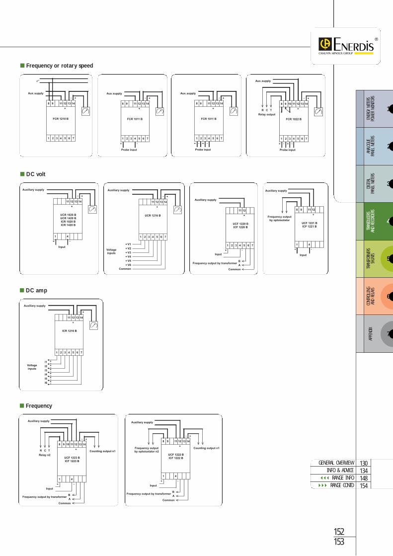
Frequency or rotary speed
+-
+ -
+
UCR 1020 B
UCR 1420 B
ICR 1020 B
ICR 1420 B
14131211
Input
41
Auxiliary supply
+-
+
UCR 1216 B
14131211
Voltage
inputs
4 765321
+ V1
+ V2
+ V3
+ V4
+ V5
+ V6
Common
Auxiliary supply
Voltage
inputs
+-
+
ICR 1216 B
14131211
4 765321
I1 +-+-+-+-+-+-
I2
I3
I4
I5
I6
Auxiliary supply
DC volt
Volt =
+ -
+
UCF 1220 B
ICF 1220 B
1211
Input
41 76532
A
Common
Auxiliary supply
Frequency output by transformer B
+ -
+
98 1211
41
UCF 1221 B
ICF 1221 B
Auxiliary supply
Frequency output
by optoisolator
Input
DC amp
+-
+
FCR 1210 B
1413121198
4 765321
Aux. supply Aux. supply
+-
+
FCR 1011 B
1413121198
4 765321
+ -
Probe input
Aux. supply
Probe input
+-
+
FCR 1011 B
1413121198
4 765321
+ -+-
Aux. supply
Probe input
+-
+
FCR 1022 B
141312119 108
4 765321
+ -+-
CR T
Relay output
+
98 1211
41
UCF 1222 B
ICF 1222 B
1413
+ -
+-
B
A
Common
Frequency output by transformer
Frequency output
by optoisolator n2
Counting output n1
Input
Auxiliary supply
+-
+
98 121110
CR T
41
UCF 1223 B
ICF 1223 B
1413
+ -
B
A
Common
Frequency output by transformer
Counting output n1
Relay n2
Input
Auxiliary supply
Frequency
152153
GENERAL OVERVIEWINFO & ADVICE
RANGE INFO RANGE CONTD
130134148154
Analo
gue
techn
ology transdu
cersTran
sducers an
d Re
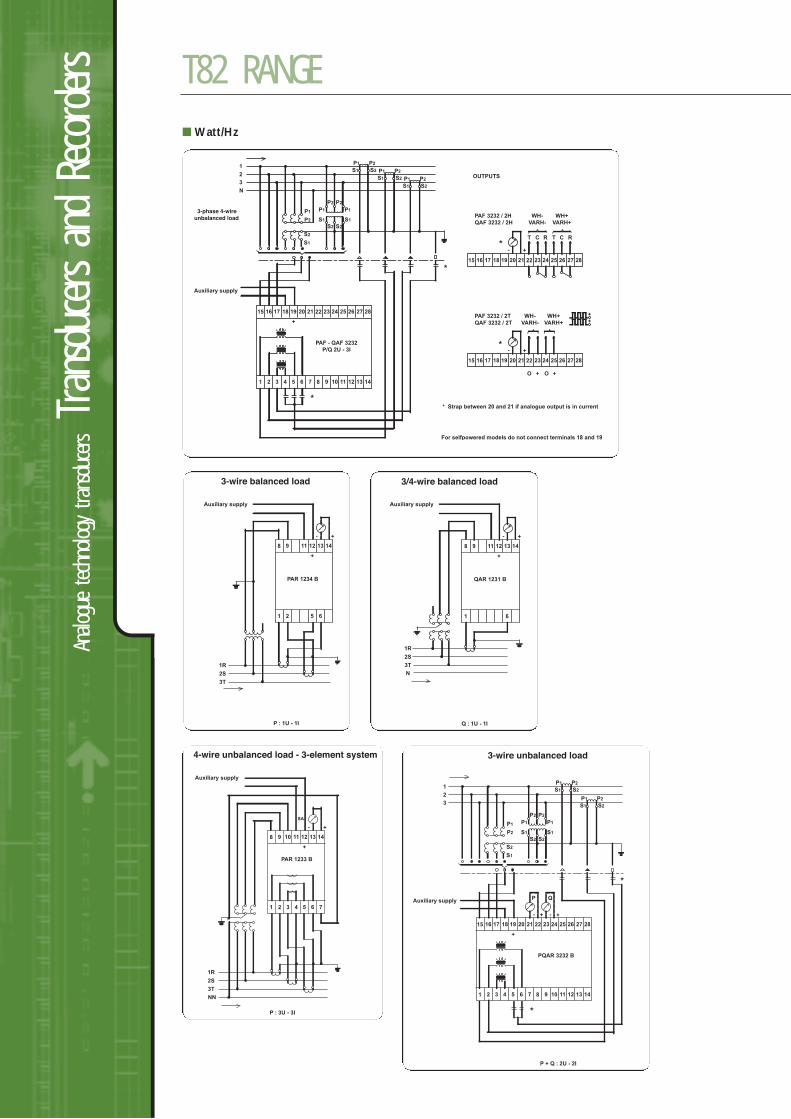
corders T82 RANGE
+
+-
21201917 181615
S2
S1
P1
1
2
3
N
P2
P1 P1
S1 S1
P1
S2 S2
P2 P2
3-phase 4-wireunbalanced load
OUTPUTS
7
*
*
*
654321
28272624 252322
21201917 181615 28272624 252322
RCTRCT
WH-
VARH-
WH+
VARH+
PAF 3232 / 2H
QAF 3232 / 2H
141312111098
P2
S1 S2 P1 P2
S1 S2 P1 P2
S1 S2
PAF - QAF 3232
P/Q 2U - 3I +
+ +O O
-*
21201917 181615 28272624 252322
WH-
VARH-
WH+
VARH+
PAF 3232 / 2T
QAF 3232 / 2T
* Strap between 20 and 21 if analogue output is in current
+
+
Auxiliary supply
For selfpowered models do not connect terminals 18 and 19
Watt/Hz
+
PAR 1234 B
1413121198
651 2
3-wire balanced load
+-
1R
2S
3T
P : 1U - 1I
Auxiliary supply
+
QAR 1231 B
1413121198
61
1R
2S
3T
N
3/4-wire balanced load
+-
Q : 1U - 1I
Auxiliary supply
4-wire unbalanced load - 3-element system
+
PAR 1233 B
141312111098
61 2 3 4 5 7
1R
2S
3T
NN
P : 3U - 3I
+-
SA
Auxiliary supply
Auxiliary supply
3-wire unbalanced load
P + Q : 2U - 2I
+-
+
21
P
+-
Q
201917 181615
S2
S1
P1
1
2
3
P2
P1 P1
S1 S1
P1
S2 S2
P2 P2
7
*
*
654321
28272624 252322
141312111098
P2
S1 S2
P1 P2
S1 S2
PQAR 3232 B
3
4
5
6
ENER
GY M
ETER
S PO
WER
MON
ITORS
ANAL
OGUE
PA
NEL
METE
RSDIGITA
L PA
NEL
METE
RSTR
ANSD
UCER
SAN
D RE
CORD
ERS
TRAN
SFOR
MERS
SHUN
TSCO
NTRO
LLING
AND
RELA
YS
7
APPE
NDIX
2
1
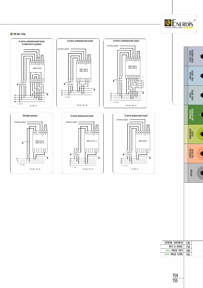
Watt-Var
4-wire unbalanced load 3-element system
+
QAR 1233 B
141312111098
61 2 3 4 5 7
1R
2S
3T
NN
Q : 3U - 3I
+-
SA
Auxiliary supply
3-wire unbalanced load
+
PAR 1232 B
QAR 1232 B
141312111098
61 2 5
1R
2S
3T
P or Q : 2U - 2I
+-
Auxiliary supply
4-wire unbalanced load
+
PAR 1232 B
QAR 1232 B
141312111098
6
1
*
3
N
2
1 2 3 4 5 7
1R
2S
3T
N
P or Q : 2U - 3I
+-
+
PAR 1211 B
QAR 1211 B
1413121198
61
Ph
N
Single-phase
+-
P or Q : 1V - 1I
Auxiliary supply
+
PAR 1211 B - 4
1413121198
61
1R
2S
3T
N
4-wire balanced load
+-
P or Q : 1V - 1I
Auxiliary supply
3-wire balanced load
+
PAR 1235 B
P : 2U - 1I
141312111098
61
1R
2S
3T
+-
Auxiliary supply
154155
GENERAL OVERVIEWINFO & ADVICE
RANGE INFO RANGE CONTD
130134148156
Analo
gue
techn
ology transdu
cersTran
sducers an
d Re
corders T82 RANGE
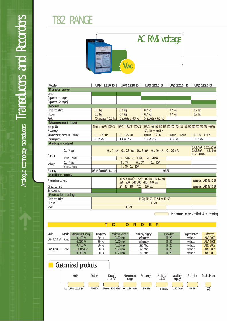
T O O R D E R
AC RMS voltage
VAC
Customized products
Model Module Measurement range Frequency Analogue output Auxiliary supply Protection Tropicalization Reference
UAN 1210 B Fixed 0...100 V 50 Hz 0...20 mA self-supply IP 20 without UANA 30020...380 V 50 Hz 0...20 mA self-supply IP 20 without UANA 30010...100 V 50 Hz 4...20 mA 220 Vac IP 20 without UARD 3002
UAR 1210 B Fixed 0...100/V3 V 50 Hz 4...20 mA 220 Vac IP 20 without UARD 30040...380 V 50 Hz 4...20 mA 220 Vac IP 20 without UARD 3003
Model Module Direct Measurement Frequency Analogue Auxiliary Protection Tropicalizationor on VT range output supply
Parameters to be specified when ordering
Model UAN 1210 B UAR 1210 B UAX 1210 B UAZ 1210 B UAZ 1220 B Transfer curveLinear Expanded (1 slope) Expanded (2 slopes) Module
Plate mounting 0.6 kg 0.7 kg 0.7 kg 0.7 kg 0.7 kgPlug-in 0.6 kg 0.7 kg 0.7 kg 0.7 kg 0.7 kgRack 10 sockets / 0.5 kg 5 sockets / 0.3 kg 5 sockets / 0.3 kgMeasurement input
Voltage Un Direct or on VT: 100/√3 110/√3 115/√3 120/√3 132/√3 90 100 110 115 120 127 132 138 180 220 250 300 360 380 440 VacFrequency 50, 60 or 400 HzMeasurement range 0…Xmax 0…1.25 Un 0…1.25 Un 0.8 Un…1.2 Un 0.8 Un…1.2 Un 0.8 Un…1.2 UnConsumption < 2 VA 1 kΩ / V 1 kΩ / V < 2 VA < 2 VAAnalogue output
0...0.1...1 mA 0...0.25...2.5 mA0…Ymax 0…1 mA 0…2.5 mA 0…5 mA 0…10 mA 0…20 mA 0...0.5...5 mA 0...1...10 mA
Current 0...2...20 mAYmin…Ymax 1…5mA 2…10mA 4…20mA
Voltage 0…Ymax 0…1V 0…5V 0…10VYmin…Ymax 1…5V 2…10V
Accuracy 0.5 % from 0.5 Un…Un 0.5 %Auxiliary supply
Alternating current 100/√3 110/√3 115/√3 100 110 115 127 Vac same as UAR 1210 B 220 230 240 380 400 440 VacDirect current 24 48 110 125 220 Vdc same as UAR 1210 BSelf-powered Protection rating
Plate mounting IP 20, IP 50, IP 54 or IP 55Plug-in IP 20Rack IP 20
E.g. UAN 1210 B Direct 100 Vac 0…120 Vac 4-20 mA50 HzFIXED 220 Vac IP 20
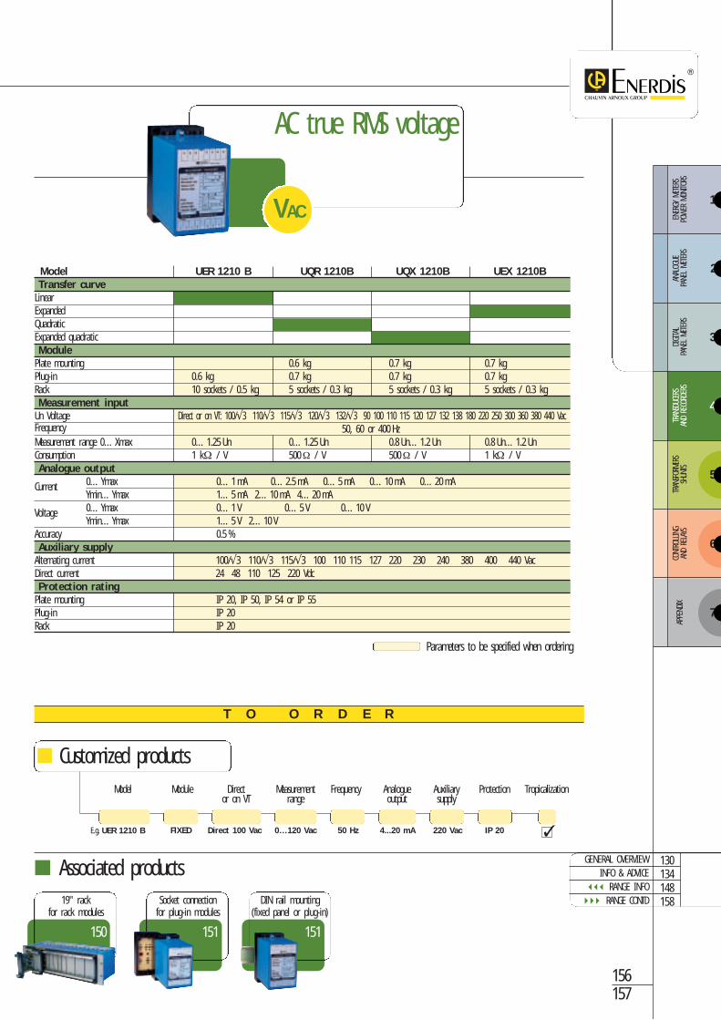
T O O R D E R
AC true RMS voltage
VAC
Parameters to be specified when ordering
Model UER 1210 B UQR 1210B UQX 1210B UEX 1210BTransfer curve
Linear Expanded Quadratic Expanded quadratic Module
Plate mounting 0.6 kg 0.7 kg 0.7 kgPlug-in 0.6 kg 0.7 kg 0.7 kg 0.7 kg Rack 10 sockets / 0.5 kg 5 sockets / 0.3 kg 5 sockets / 0.3 kg 5 sockets / 0.3 kgMeasurement input
Un Voltage Direct or on VT: 100/√3 110/√3 115/√3 120/√3 132/√3 90 100 110 115 120 127 132 138 180 220 250 300 360 380 440 VacFrequency 50, 60 or 400 HzMeasurement range 0…Xmax 0…1.25 Un 0…1.25 Un 0.8 Un…1.2 Un 0.8 Un…1.2 UnConsumption 1 kΩ / V 500Ω / V 500Ω / V 1 kΩ / VAnalogue output
Current 0…Ymax 0…1 mA 0…2.5 mA 0…5 mA 0…10 mA 0…20 mA Ymin…Ymax 1…5 mA 2…10 mA 4…20 mA
Voltage 0…Ymax 0…1 V 0…5 V 0…10 VYmin…Ymax 1…5 V 2…10 V
Accuracy 0.5 %Auxiliary supply
Alternating current 100/√3 110/√3 115/√3 100 110 115 127 220 230 240 380 400 440 VacDirect current 24 48 110 125 220 VdcProtection rating
Plate mounting IP 20, IP 50, IP 54 or IP 55Plug-in IP 20Rack IP 20
156157
Customized productsModel Module Direct Measurement Frequency Analogue Auxiliary Protection Tropicalization
or on VT range output supply
E.g. UER 1210 B Direct 100 Vac 0…120 Vac 4...20 mA50 HzFIXED 220 Vac IP 20
151
Socket connectionfor plug-in modules
151
DIN rail mounting(fixed panel or plug-in)
150
19" rackfor rack modules
Associated productsGENERAL OVERVIEW
INFO & ADVICE RANGE INFO RANGE CONTD
130134148158
3
4
5
6
ENER
GY M
ETER
S PO
WER
MON
ITORS
ANAL
OGUE
PA
NEL
METE
RSDIGITA
L PA
NEL
METE
RSTR
ANSD
UCER
SAN
D RE
CORD
ERS
TRAN
SFOR
MERS
SHUN
TSCO
NTRO
LLING
AND
RELA
YS
7
APPE
NDIX
2
1
Analo
gue
techn
ology transdu
cersTran
sducers an
d Re
corders T82 RANGE
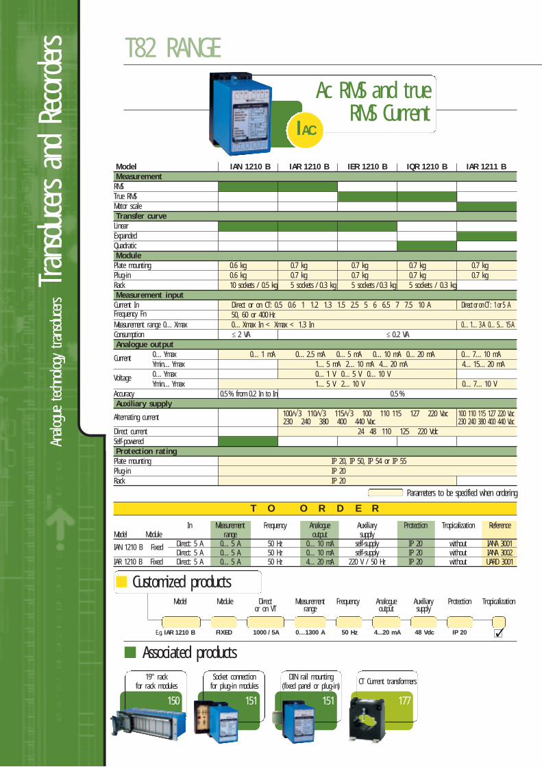
T O O R D E R
Ac RMS and trueRMS Current
IAC
In Measurement Frequency Analogue Auxiliary Protection Tropicalization ReferenceModel Module range output supply
IAN 1210 B Fixed Direct: 5 A 0…5 A 50 Hz 0…10 mA self-supply IP 20 without IANA 3001Direct: 5 A 0…5 A 50 Hz 0…10 mA self-supply IP 20 without IANA 3002
IAR 1210 B Fixed Direct: 5 A 0…5 A 50 Hz 4…20 mA 220 V / 50 Hz IP 20 without UARD 3001
Model IAN 1210 B IAR 1210 B IER 1210 B IQR 1210 B IAR 1211 B MeasurementRMS True RMS Motor scale Transfer curveLinear Expanded Quadratic ModulePlate mounting 0.6 kg 0.7 kg 0.7 kg 0.7 kg 0.7 kgPlug-in 0.6 kg 0.7 kg 0.7 kg 0.7 kg 0.7 kgRack 10 sockets / 0.5 kg 5 sockets / 0.3 kg 5 sockets / 0.3 kg 5 sockets / 0.3 kgMeasurement inputCurrent In Direct or on CT: 0.5 0.6 1 1.2 1.3 1.5 2.5 5 6 6.5 7 7.5 10 A Direct or on CT : 1 or 5 AFrequency Fn 50, 60 or 400 HzMeasurement range 0…Xmax 0…Xmax In < Xmax < 1.3 In 0…1…3 A 0…5…15 AConsumption 2 VA 0.2 VAAnalogue output
Current 0…Ymax 0…1 mA 0…2.5 mA 0…5 mA 0…10 mA 0…20 mA 0…7…10 mA Ymin…Ymax 1…5 mA 2…10 mA 4…20 mA 4…15…20 mA
Voltage 0…Ymax 0…1 V 0…5 V 0…10 VYmin…Ymax 1…5 V 2…10 V 0…7…10 V
Accuracy 0.5 % from 0.2 In to In 0.5 %Auxiliary supply
Alternating current 100/√3 110/√3 115/√3 100 110 115 127 220 Vac 100 110 115 127 220 Vac230 240 380 400 440 Vac 230 240 380 400 440 Vac
Direct current 24 48 110 125 220 VdcSelf-powered Protection ratingPlate mounting IP 20, IP 50, IP 54 or IP 55Plug-in IP 20Rack IP 20
Customized productsModel Module Direct Measurement Frequency Analogue Auxiliary Protection Tropicalization
or on VT range output supply
E.g. IAR 1210 B 1000 / 5A 0…1300 A 4...20 mA50 HzFIXED 48 Vdc IP 20
177
CT Current transformers
151
Socket connectionfor plug-in modules
151
DIN rail mounting(fixed panel or plug-in)
150
19" rackfor rack modules
Associated products
Parameters to be specified when ordering
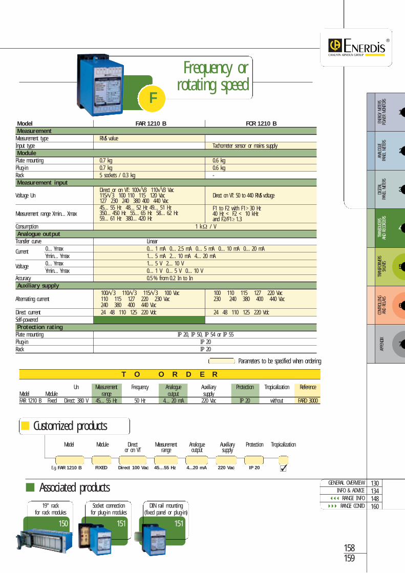
Frequency or rotating speed
Un Measurement Frequency Analogue Auxiliary Protection Tropicalization ReferenceModel Module range output supplyFAR 1210 B Fixed Direct: 380 V 45…55 Hz 50 Hz 4…20 mA 220 Vac IP 20 without FARD 3000
T O O R D E R
F
158159
Model FAR 1210 B FCR 1210 B MeasurementMeasurement type RMS valueInput type Tachometer sensor or mains supplyModulePlate mounting 0.7 kg 0.6 kgPlug-in 0.7 kg 0.6 kgRack 5 sockets / 0.3 kg -Measurement input
Direct or on VT: 100√V3 110√V3 VacVoltage Un 115/√3 100 110 115 120 Vac Direct on VT: 50 to 440 RMS voltage
127 230 240 380 400 440 Vac45…55 Hz 48…52 Hz 49…51 Hz F1 to F2 with F1 30 Hz
Measurement range Xmin…Xmax 350…450 Hz 55…65 Hz 58…62 Hz 40 Hz < F2 < 10 kHz59…61 Hz 380…420 Hz and F2/F1 1.3
Consumption 1 kΩ / VAnalogue outputTransfer curve Linear
Current 0…Ymax 0…1 mA 0…2.5 mA 0…5 mA 0…10 mA 0…20 mAYmin…Ymax 1…5 mA 2…10 mA 4…20 mA
Voltage 0…Ymax 1…5 V 2…10 VYmin…Ymax 0…1 V 0…5 V 0…10 V
Accuracy 0.5 % from 0.2 In to InAuxiliary supply
100/√3 110/√3 115/√3 100 Vac 100 110 115 127 220 VacAlternating current 110 115 127 220 230 Vac 230 240 380 400 440 Vac
240 380 400 440 VacDirect current 24 48 110 125 220 Vdc 24 48 110 125 220 VdcSelf-powered Protection ratingPlate mounting IP 20, IP 50, IP 54 or IP 55Plug-in IP 20Rack IP 20
Customized productsModel Module Direct Measurement Analogue Auxiliary Protection Tropicalization
or on VT range output supply
E.g. FAR 1210 B Direct 100 Vac 45…55 Hz 220 Vac4...20 mAFIXED IP 20
151
Socket connectionfor plug-in modules
151
DIN rail mounting(fixed panel or plug-in)
150
19" rackfor rack modules
Associated productsGENERAL OVERVIEW
INFO & ADVICE RANGE INFO RANGE CONTD
130134148160
Parameters to be specified when ordering
3
4
5
6
ENER
GY M
ETER
S PO
WER
MON
ITORS
ANAL
OGUE
PA
NEL
METE
RSDIGITA
L PA
NEL
METE
RSTR
ANSD
UCER
SAN
D RE
CORD
ERS
TRAN
SFOR
MERS
SHUN
TSCO
NTRO
LLING
AND
RELA
YS
7
APPE
NDIX
2
1
Analo
gue
techn
ology transdu
cersTran
sducers an
d Re
corders T82 RANGE
T O O R D E R
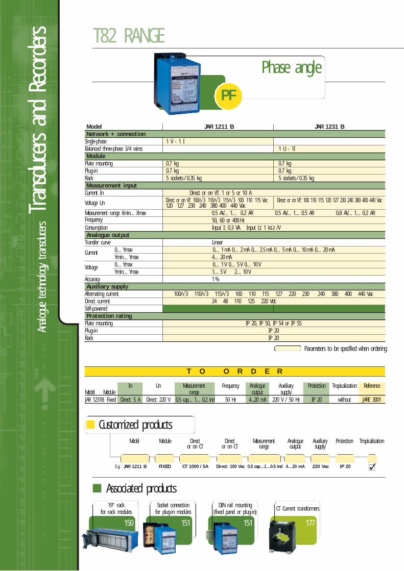
In Un Measurement Frequency Analogue Auxiliary Protection Tropicalization ReferenceModel Module range output supplyJAR 1231B Fixed Direct: 5 A Direct: 220 V 0.5 cap…1…0.2 ind 50 Hz 4...20 mA 220 V / 50 Hz IP 20 without JARE 3001
Parameters to be specified when ordering
Model JAR 1211 B JAR 1231 BNetwork + connectionSingle-phase 1 V - 1 IBalanced three-phase 3/4 wires 1 U - 1IModulePlate mounting 0.7 kg 0.7 kgPlug-in 0.7 kg 0.7 kgRack 5 sockets / 0.35 kg 5 sockets / 0.35 kgMeasurement inputCurrent In Direct or on VT: 1 or 5 or 10 A
Voltage Un Direct or on VT: 100/√3 110/√3 115/√3 100 110 115 Vac Direct or on VT: 100 110 115 120 127 230 240 380 400 440 Vac120 127 230 240 380 400 440 Vac
Measurement range Xmin…Xmax 0.5 AV…1… 0.2 AR 0.5 AV…1…0.5 AR 0.8 AV…1…0.2 ARFrequency 50, 60 or 400 HzConsumption Input I: 0.3 VA Input U: 1 kΩ /VAnalogue outputTransfer curve Linear
Current 0…Ymax 0…1 mA 0…2 mA 0…2.5 mA 0…5 mA 0…10 mA 0…20 mA Ymin…Ymax 4…20 mA
Voltage 0…Ymax 0…1 V 0…5 V 0…10 VYmin…Ymax 1…5 V 2…10 V
Accuracy 1 %Auxiliary supplyAlternating current 100/√3 110/√3 115/√3 100 110 115 127 220 230 240 380 400 440 VacDirect current 24 48 110 125 220 VdcSelf-powered Protection ratingPlate mounting IP 20, IP 50, IP 54 or IP 55Plug-in IP 20Rack IP 20
Customized productsModel Module Direct Direct Measurement Analogue Auxiliary Protection Tropicalization
or on CT or on CT range output supply
E.g. JAR 1211 B CT 1000 / 5A 0.5 cap…1…0.5 indDirect: 100 VacFIXED 220 Vac4…20 mA IP 20
177
CT Current transformers
151
Socket connectionfor plug-in modules
150
19" rackfor rack modules
Associated products
Phase angle
PF
151
DIN rail mounting(fixed panel or plug-in)
T O O R D E R
Parameters to be specified when ordering
160161
Customized productsModel Module Direct Measurement Analogue Auxiliary Protection Tropicalization
or on CT or on CT range output supply
E.g. JAR 1221 B CT 1000 / 5A 60…0…60°Direct: 100 VacFIXED 220 Vac4...20 mA IP 20
151
Socket connectionfor plug-in modules
150
19" rackfor rack modules
Associated products
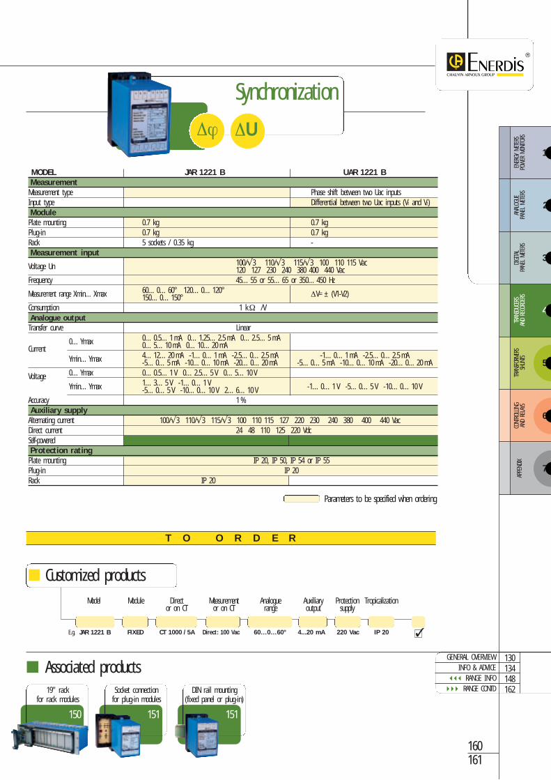
MODEL JAR 1221 B UAR 1221 BMeasurementMeasurement type Phase shift between two Uac inputsInput type Differential between two Uac inputs (V1 and V2)ModulePlate mounting 0.7 kg 0.7 kgPlug-in 0.7 kg 0.7 kgRack 5 sockets / 0.35 kg -Measurement input
Voltage Un 100/√3 110/√3 115/√3 100 110 115 Vac120 127 230 240 380 400 440 Vac
Frequency 45…55 or 55…65 or 350…450 Hz
Measurement range Xmin…Xmax 60…0…60° 120…0…120° ∆V=± (V1-V2)150…0…150°Consumption 1 kΩ /VAnalogue outputTransfer curve Linear
0…Ymax 0…0.5…1 mA 0…1.25…2.5 mA 0…2.5…5 mACurrent 0…5…10 mA 0…10…20 mA
Ymin…Ymax 4…12…20 mA -1…0…1 mA -2.5…0…2.5 mA -1…0…1 mA -2.5…0…2.5 mA-5…0…5 mA -10…0…10 mA -20…0…20 mA -5…0…5 mA -10…0…10 mA -20…0…20 mA
Voltage 0…Ymax 0…0.5…1 V 0…2.5…5 V 0…5…10 V
Ymin…Ymax 1…3…5 V -1…0…1 V -1…0…1 V -5…0…5 V -10…0…10 V-5…0…5 V -10…0…10 V 2…6…10 VAccuracy 1 %Auxiliary supplyAlternating current 100/√3 110/√3 115/√3 100 110 115 127 220 230 240 380 400 440 VacDirect current 24 48 110 125 220 VdcSelf-powered Protection ratingPlate mounting IP 20, IP 50, IP 54 or IP 55 Plug-in IP 20Rack IP 20
Synchronization
∆U∆ϕ
151
DIN rail mounting(fixed panel or plug-in)
GENERAL OVERVIEWINFO & ADVICE
RANGE INFO RANGE CONTD
130134148162
3
4
5
6
ENER
GY M
ETER
S PO
WER
MON
ITORS
ANAL
OGUE
PA
NEL
METE
RSDIGITA
L PA
NEL
METE
RSTR
ANSD
UCER
SAN
D RE
CORD
ERS
TRAN
SFOR
MERS
SHUN
TSCO
NTRO
LLING
AND
RELA
YS
7
APPE
NDIX
2
1
Analo
gue
techn
ology transdu
cersTran
sducers an
d Re
corders T82 RANGE
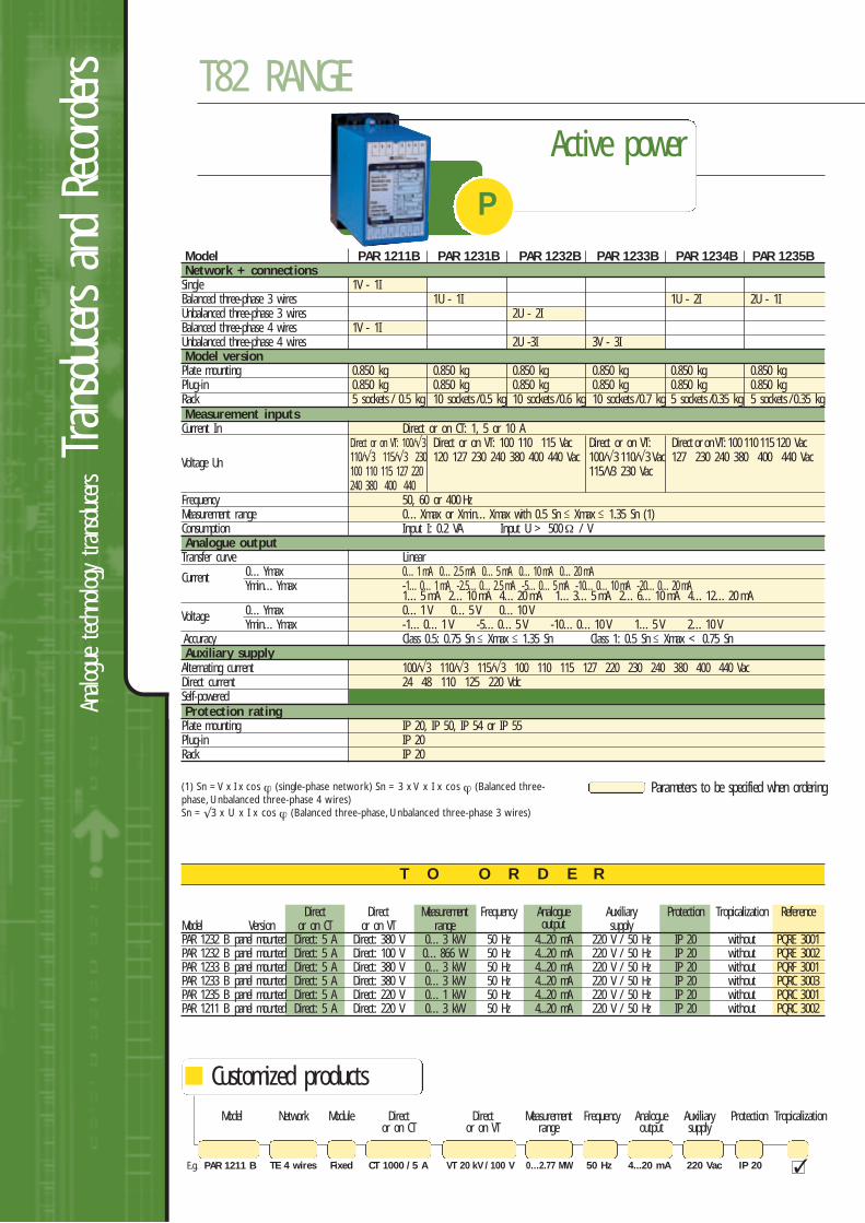
Direct Direct Measurement Frequency Analogue Auxiliary Protection Tropicalization ReferenceModel Version or on CT or on VT range output supplyPAR 1232 B panel mounted Direct: 5 A Direct: 380 V 0…3 kW 50 Hz 4...20 mA 220 V / 50 Hz IP 20 without PQRE 3001PAR 1232 B panel mounted Direct: 5 A Direct: 100 V 0…866 W 50 Hz 4...20 mA 220 V / 50 Hz IP 20 without PQRE 3002PAR 1233 B panel mounted Direct: 5 A Direct: 380 V 0…3 kW 50 Hz 4...20 mA 220 V / 50 Hz IP 20 without PQRF 3001PAR 1233 B panel mounted Direct: 5 A Direct: 380 V 0…3 kW 50 Hz 4...20 mA 220 V / 50 Hz IP 20 without PQRC 3003PAR 1235 B panel mounted Direct: 5 A Direct: 220 V 0…1 kW 50 Hz 4...20 mA 220 V / 50 Hz IP 20 without PQRC 3001PAR 1211 B panel mounted Direct: 5 A Direct: 220 V 0…3 kW 50 Hz 4...20 mA 220 V / 50 Hz IP 20 without PQRC 3002
T O O R D E R
Customized productsModel Network Module Direct Direct Measurement Frequency Analogue Auxiliary Protection Tropicalization
or on CT or on VT range output supply
E.g. PAR 1211 B CT 1000 / 5 A 0…2.77 MWVT 20 kV / 100 VFixedTE 4 wires 220 Vac50 Hz 4...20 mA IP 20
Active power
PModel PAR 1211B PAR 1231B PAR 1232B PAR 1233B PAR 1234B PAR 1235B Network + connectionsSingle 1V - 1IBalanced three-phase 3 wires 1U - 1I 1U - 2I 2U - 1IUnbalanced three-phase 3 wires 2U - 2IBalanced three-phase 4 wires 1V - 1IUnbalanced three-phase 4 wires 2U -3I 3V - 3IModel versionPlate mounting 0.850 kg 0.850 kg 0.850 kg 0.850 kg 0.850 kg 0.850 kgPlug-in 0.850 kg 0.850 kg 0.850 kg 0.850 kg 0.850 kg 0.850 kgRack 5 sockets / 0.5 kg 10 sockets / 0.5 kg 10 sockets / 0.6 kg 10 sockets / 0.7 kg 5 sockets /0.35 kg 5 sockets /0.35 kgMeasurement inputsCurrent In Direct or on CT: 1, 5 or 10 A
Direct or on VT: 100/√3 Direct or on VT: 100 110 115 Vac Direct or on VT: Direct or on VT: 100 110 115 120 Vac
Voltage Un 110/√3 115/√3 230 120 127 230 240 380 400 440 Vac 100/√3 110/√3 Vac 127 230 240 380 400 440 Vac100 110 115 127 220 115/V3 230 Vac240 380 400 440
Frequency 50, 60 or 400 HzMeasurement range 0…Xmax or Xmin…Xmax with 0.5 Sn Xmax 1.35 Sn (1)Consumption Input I: 0.2 VA Input U > 500Ω / VAnalogue outputTransfer curve Linear
Current 0…Ymax 0…1 mA 0…2.5 mA 0…5 mA 0…10 mA 0…20 mA Ymin…Ymax -1…0…1 mA -2.5…0…2.5 mA -5…0…5 mA -10…0…10 mA -20…0…20 mA
1…5 mA 2…10 mA 4…20 mA 1…3…5 mA 2…6…10 mA 4…12…20 mA
Voltage 0…Ymax 0…1 V 0…5 V 0…10 VYmin…Ymax -1…0…1 V -5…0…5 V -10…0…10 V 1…5 V 2…10 V
Accuracy Class 0.5: 0.75 Sn Xmax 1.35 Sn Class 1: 0.5 Sn Xmax < 0.75 SnAuxiliary supplyAlternating current 100/√3 110/√3 115/√3 100 110 115 127 220 230 240 380 400 440 VacDirect current 24 48 110 125 220 VdcSelf-powered Protection ratingPlate mounting IP 20, IP 50, IP 54 or IP 55 Plug-in IP 20Rack IP 20
Parameters to be specified when ordering(1) Sn = V x I x cos ϕ (single-phase network) Sn = 3 x V x I x cos ϕ (Balanced three-phase, Unbalanced three-phase 4 wires)Sn = √3 x U x I x cos ϕ (Balanced three-phase, Unbalanced three-phase 3 wires)
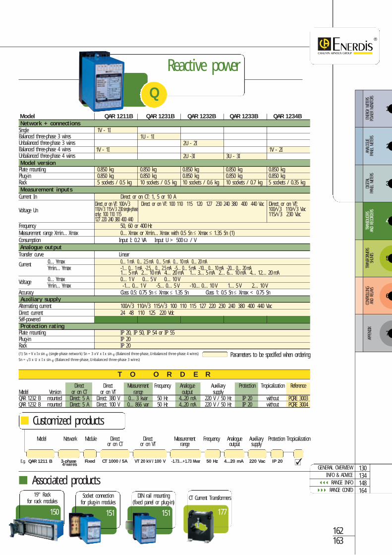
Direct Direct Measurement Frequency Analogue Auxiliary Protection Tropicalization ReferenceModel Version or on CT or on VT range output supplyQAR 1232 B mounted Direct: 5 A Direct: 380 V 0…3 kvar 50 Hz 4...20 mA 220 V / 50 Hz IP 20 without PQRE 3003QAR 1232 B mounted Direct: 5 A Direct: 100 V 0…866 var 50 Hz 4...20 mA 220 V / 50 Hz IP 20 without PQRE 3004
T O O R D E R
Model QAR 1211B QAR 1231B QAR 1232B QAR 1233B QAR 1234B Network + connectionsSingle 1V - 1IBalanced three-phase 3 wires 1U - 1IUnbalanced three-phase 3 wires 2U - 2IBalanced three-phase 4 wires 1V - 1I 1V - 2IUnbalanced three-phase 4 wires 2U -3I 3U - 3IModel versionPlate mounting 0.850 kg 0.850 kg 0.850 kg 0.850 kg 0.850 kgPlug-in 0.850 kg 0.850 kg 0.850 kg 0.850 kg 0.850 kgRack 5 sockets / 0.5 kg 10 sockets / 0.5 kg 10 sockets / 0.6 kg 10 sockets / 0.7 kg 5 sockets / 0.35 kgMeasurement inputsCurrent In Direct or on CT: 1, 5 or 10 A
Direct or on VT: 100/√3 Direct or on VT: 100 110 115 120 127 230 240 380 400 440 Vac Direct or on VT: Voltage Un 110/√3 115/√3 230 single-phase 100/√3 110/√3 Vac
only: 100 110 115 115/√3 230 Vac127 220 240 380 400 440
Frequency 50, 60 or 400 HzMeasurement range Xmin…Xmax 0…Xmax or Xmin…Xmax with 0.5 Sn Xmax 1.35 Sn (1)Consumption Input I: 0.2 VA Input U > 500Ω / VAnalogue outputTransfer curve Linear
Current 0…Ymax 0…1 mA 0…2.5 mA 0…5 mA 0…10 mA 0…20 mA Ymin…Ymax -1…0…1 mA -2.5…0…2.5 mA -5…0…5 mA -10…0…10 mA -20…0…20 mA
1…5 mA 2…10 mA 4…20 mA 1…3…5 mA 2…6…10 mA 4…12…20 mA
Voltage 0…Ymax 0…1 V 0…5 V 0…10 VYmin…Ymax -1…0…1 V -5…0…5 V -10…0…10 V 1…5 V 2…10 V
Accuracy Class 0.5: 0.75 Sn Xmax 1.35 Sn Class 1: 0.5 Sn Xmax < 0.75 SnAuxiliary supplyAlternating current 100/√3 110/√3 115/√3 100 110 115 127 220 230 240 380 400 440 VacDirect current 24 48 110 125 220 VdcSelf-powered Protection ratingPlate mounting IP 20, IP 50, IP 54 or IP 55 Plug-in IP 20Rack IP 20
Parameters to be specified when ordering(1) Sn = V x I x sin ϕ (single-phase network) Sn = 3 x V x I x sin ϕ (Balanced three-phase,Unbalanced three-phase 4 wires)
Sn = √3 x U x I x sin ϕ (Balanced three-phase, Unbalanced three-phase 3 wires)
162163
Customized productsModel Network Module Direct Direct Measurement Frequency Analogue Auxiliary Protection Tropicalization
or on CT or on VT range output supply
E.g. QAR 1211 B CT 1000 / 5A -1.73…+1.73 MvarVT 20 kV / 100 VFixed3-phase 4-wires
220 Vac50 Hz 4...20 mA IP 20
177
CT Current Transformers
151
Socket connectionfor plug-in modules
150
19'' Rackfor rack modules
Associated products
Reactive power
Q
151
DIN rail mounting(fixed panel or plug-in)
GENERAL OVERVIEWINFO & ADVICE
RANGE INFO RANGE CONTD
130134148164
3
4
5
6
ENER
GY M
ETER
S PO
WER
MON
ITORS
ANAL
OGUE
PA
NEL
METE
RSDIGITA
L PA
NEL
METE
RSTR
ANSD
UCER
SAN
D RE
CORD
ERS
TRAN
SFOR
MERS
SHUN
TSCO
NTRO
LLING
AND
RELA
YS
7
APPE
NDIX
2
1
Analo
gue
techn
ology transdu
cersTran
sducers an
d Re
corders T82 RANGE
T O O R D E R
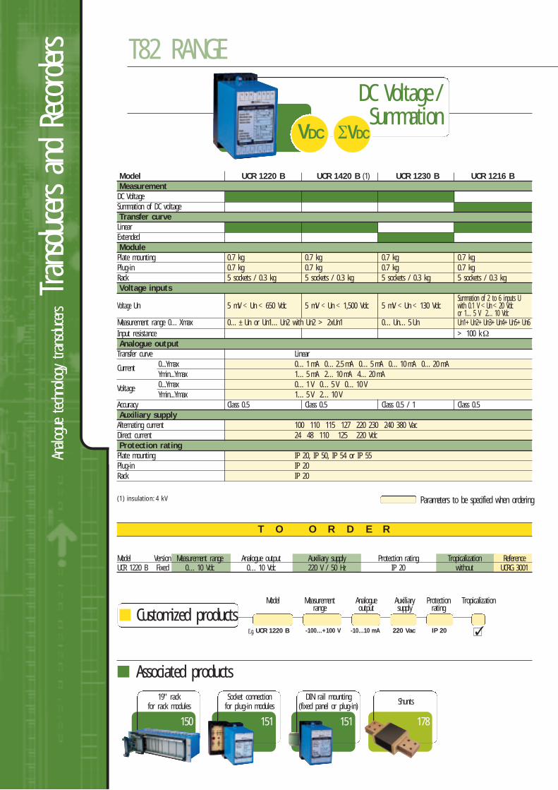
Model Version Measurement range Analogue output Auxiliary supply Protection rating Tropicalization ReferenceUCR 1220 B Fixed 0…10 Vdc 0…10 Vdc 220 V / 50 Hz IP 20 without UCRG 3001
Parameters to be specified when ordering
Customized productsModel Measurement Analogue Auxiliary Protection Tropicalization
range output supply rating
E.g. UCR 1220 B -100…+100 V -10…10 mA 220 Vac IP 20
151
Socket connectionfor plug-in modules
150
19" rackfor rack modules
Associated products
178
Shunts
DC Voltage /Summation
VDC ΣVDC
(1) insulation: 4 kV
Model UCR 1220 B UCR 1420 B (1) UCR 1230 B UCR 1216 BMeasurementDC Voltage Summation of DC voltage Transfer curveLinear Extended ModulePlate mounting 0.7 kg 0.7 kg 0.7 kg 0.7 kgPlug-in 0.7 kg 0.7 kg 0.7 kg 0.7 kgRack 5 sockets / 0.3 kg 5 sockets / 0.3 kg 5 sockets / 0.3 kg 5 sockets / 0.3 kgVoltage inputs
Summation of 2 to 6 inputs UVoltage Un 5 mV Un 650 Vdc 5 mV Un 1,500 Vdc 5 mV Un 130 Vdc with 0.1 V Un 20 Vdc
or 1…5 V 2…10 VdcMeasurement range 0…Xmax 0…±Un or Un1…Un2 with Un2 > 2xUn1 0…Un…5 Un Un1+Un2+Un3+Un4+Un5+Un6Input resistance > 100 kΩAnalogue outputTransfer curve Linear
Current 0...Ymax 0…1 mA 0…2.5 mA 0…5 mA 0…10 mA 0…20 mAYmin...Ymax 1…5 mA 2…10 mA 4…20 mA
Voltage 0...Ymax 0…1 V 0…5 V 0…10 VYmin...Ymax 1…5 V 2…10 V
Accuracy Class 0.5 Class 0.5 Class 0.5 / 1 Class 0.5Auxiliary supplyAlternating current 100 110 115 127 220 230 240 380 VacDirect current 24 48 110 125 220 VdcProtection ratingPlate mounting IP 20, IP 50, IP 54 or IP 55 Plug-in IP 20Rack IP 20
151
DIN rail mounting(fixed panel or plug-in)
Customized productsModel Version Measurement Analogue Auxiliary Protection Tropicalization
range output supply rating
T O O R D E R
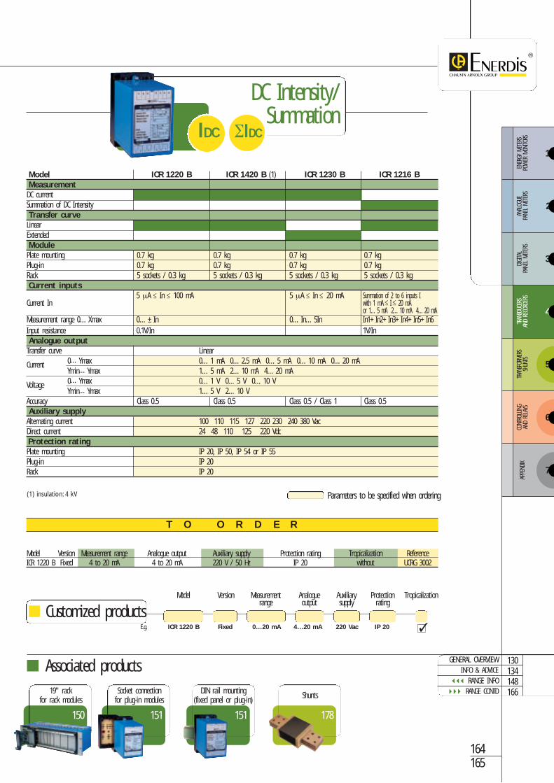
Model Version Measurement range Analogue output Auxiliary supply Protection rating Tropicalization ReferenceICR 1220 B Fixed 4 to 20 mA 4 to 20 mA 220 V / 50 Hz IP 20 without UCRG 3002
Parameters to be specified when ordering
ICR 1220 B 0…20 mA 4…20 mA 220 VacFixed IP 20
164165
178
Shunts
151
Socket connectionfor plug-in modules
150
19" rackfor rack modules
Associated products
DC Intensity/Summation
ΣIDCIDC
(1) insulation: 4 kV
Model ICR 1220 B ICR 1420 B (1) ICR 1230 B ICR 1216 BMeasurementDC current Summation of DC Intensity Transfer curveLinear Extended ModulePlate mounting 0.7 kg 0.7 kg 0.7 kg 0.7 kgPlug-in 0.7 kg 0.7 kg 0.7 kg 0.7 kgRack 5 sockets / 0.3 kg 5 sockets / 0.3 kg 5 sockets / 0.3 kg 5 sockets / 0.3 kgCurrent inputs
5 µA In 100 mA 5 µA In 20 mA Summation of 2 to 6 inputs ICurrent In with 1 mA I 20 mA
or 1…5 mA 2…10 mA 4…20 mAMeasurement range 0…Xmax 0…±In 0…In…5In In1+In2+In3+In4+In5+In6Input resistance 0.1V/In 1V/InAnalogue outputTransfer curve Linear
Current 0…Ymax 0…1 mA 0…2.5 mA 0…5 mA 0…10 mA 0…20 mAYmin…Ymax 1…5 mA 2…10 mA 4…20 mA
Voltage 0…Ymax 0…1 V 0…5 V 0…10 VYmin…Ymax 1…5 V 2…10 V
Accuracy Class 0.5 Class 0.5 Class 0.5 / Class 1 Class 0.5Auxiliary supplyAlternating current 100 110 115 127 220 230 240 380 VacDirect current 24 48 110 125 220 VdcProtection ratingPlate mounting IP 20, IP 50, IP 54 or IP 55Plug-in IP 20Rack IP 20
151
DIN rail mounting(fixed panel or plug-in)
GENERAL OVERVIEWINFO & ADVICE
RANGE INFO RANGE CONTD
130134148166
E.g.
3
4
5
6
ENER
GY M
ETER
S PO
WER
MON
ITORS
ANAL
OGUE
PA
NEL
METE
RSDIGITA
L PA
NEL
METE
RSTR
ANSD
UCER
SAN
D RE
CORD
ERS
TRAN
SFOR
MERS
SHUN
TSCO
NTRO
LLING
AND
RELA
YS
7
APPE
NDIX
2
1
Analo
gue
techn
ology transdu
cersTran
sducers an
d Re
corders T82 RANGE
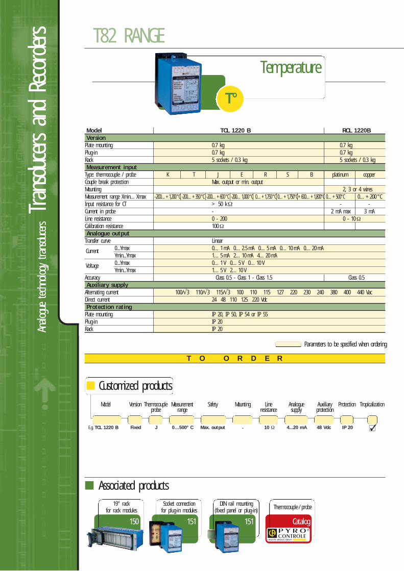
T O O R D E R
Parameters to be specified when ordering
Customized productsModel Version Thermocouple Measurement Safety Mounting Line Analogue Auxiliary Protection Tropicalization
probe range resistance supply protection
E.g. TCL 1220 B 0…500° C Max. output -JFixed 48 Vdc10 Ω 4...20 mA IP 20
151
Socket connectionfor plug-in modules
150
19" rackfor rack modules
Associated products
Temperature
T°
151
DIN rail mounting(fixed panel or plug-in)
Catalog
Thermocouple / probe
Model TCL 1220 B RCL 1220BVersionPlate mounting 0.7 kg 0.7 kgPlug-in 0.7 kg 0.7 kgRack 5 sockets / 0.3 kg 5 sockets / 0.3 kgMeasurement inputType: thermocouple / probe K T J E R S B platinum copperCouple break protection Max. output or min. outputMounting 2, 3 or 4 wiresMeasurement range Xmin…Xmax -200…+1,200°C -200…+350°C -200…+600°C -200…1,000°C 0…+1,750°C 0…+1,750°C+600…+1,800°C 0…+500°C 0…+200 °CInput resistance for CT > 50 kΩ - -Current in probe - 2 mA max 3 mALine resistance 0 - 200 0 - 10ΩCalibration resistance 100ΩAnalogue outputTransfer curve Linear
Current 0...Ymax 0…1 mA 0…2.5 mA 0…5 mA 0…10 mA 0…20 mAYmin...Ymax 1…5 mA 2…10 mA 4…20 mA
Voltage 0...Ymax 0…1 V 0…5 V 0…10 VYmin...Ymax 1…5 V 2…10 V
Accuracy Class 0.5 - Class 1 - Class 1.5 Class 0.5Auxiliary supplyAlternating current 100/√3 110/√3 115/√3 100 110 115 127 220 230 240 380 400 440 Vac Direct current 24 48 110 125 220 VdcProtection ratingPlate mounting IP 20, IP 50, IP 54 or IP 55Plug-in IP 20Rack IP 20
132134148
SELECTION GUIDEINFO & ADVICE
RANGE INFO
Parameters to be specified when ordering
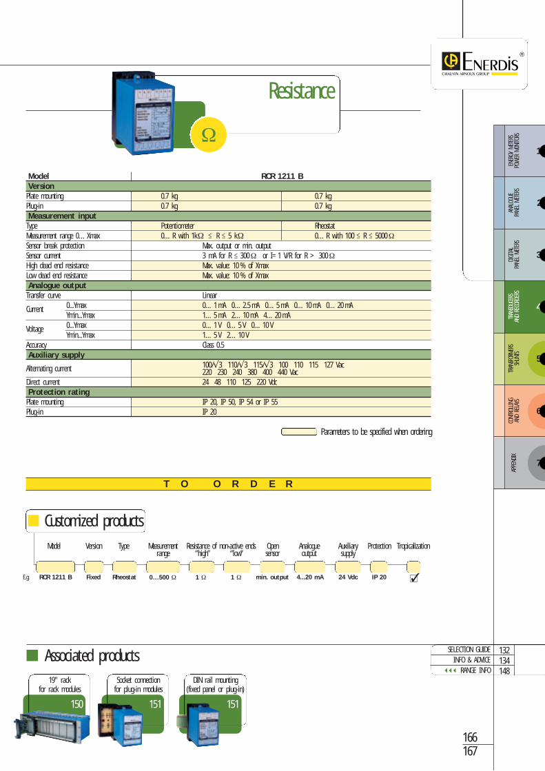
Model RCR 1211 BVersionPlate mounting 0.7 kg 0.7 kgPlug-in 0.7 kg 0.7 kgMeasurement inputType Potentiometer RheostatMeasurement range 0…Xmax 0…R with 1kΩ R 5 kΩ 0…R with 100 R 5000ΩSensor break protection Max. output or min. outputSensor current 3 mA for R 300Ω or I=1 V/R for R > 300ΩHigh dead end resistance Max. value: 10 % of XmaxLow dead end resistance Max. value: 10 % of XmaxAnalogue outputTransfer curve Linear
Current 0...Ymax 0…1 mA 0…2.5 mA 0…5 mA 0…10 mA 0…20 mAYmin...Ymax 1…5 mA 2…10 mA 4…20 mA
Voltage 0...Ymax 0…1 V 0…5 V 0…10 VYmin...Ymax 1…5 V 2…10 V
Accuracy Class 0.5Auxiliary supply
Alternating current 100/√3 110/√3 115/√3 100 110 115 127 Vac220 230 240 380 400 440 Vac
Direct current 24 48 110 125 220 VdcProtection ratingPlate mounting IP 20, IP 50, IP 54 or IP 55 Plug-in IP 20
166167
T O O R D E R
Customized productsModel Version Type Measurement Resistance of non-active ends Open Analogue Auxiliary Protection Tropicalization
range “high” “low” sensor output supply
RCR 1211 B 0…500 Ω 1 Ω 1 ΩRheostatFixed 24 Vdcmin. output 4...20 mA IP 20
151
Socket connectionfor plug-in modules
150
19" rackfor rack modules
Associated products
Resistance
Ω
151
DIN rail mounting(fixed panel or plug-in)
E.g.
3
4
5
6
ENER
GY M
ETER
S PO
WER
MON
ITORS
ANAL
OGUE
PA
NEL
METE
RSDIGITA
L PA
NEL
METE
RSTR
ANSD
UCER
SAN
D RE
CORD
ERS
TRAN
SFOR
MERS
SHUN
TSCO
NTRO
LLING
AND
RELA
YS
7
APPE
NDIX
2
1
Digit
al converter
sTran
sducers an
d Re
corders ENERIUM RANGE
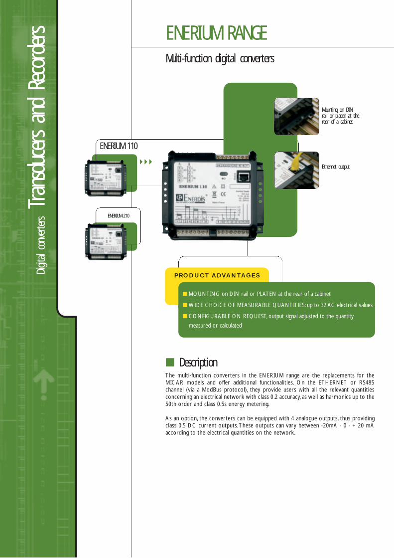
Multi-function digital converters
The multi-function converters in the ENERIUM range are the replacements for theMICAR models and offer additional functionalities. On the ETHERNET or RS485channel (via a ModBus protocol), they provide users with all the relevant quantitiesconcerning an electrical network with class 0.2 accuracy, as well as harmonics up to the50th order and class 0.5s energy metering.
As an option, the converters can be equipped with 4 analogue outputs, thus providingclass 0.5 DC current outputs.These outputs can vary between -20mA - 0 - + 20 mAaccording to the electrical quantities on the network.
Description
ENERIUM 210
PRODUCT ADVANTAGES
MOUNTING on DIN rail or PLATEN at the rear of a cabinet
WIDE CHOICE OF MEASURABLE QUANTITIES: up to 32 AC electrical values
CONFIGURABLE ON REQUEST, output signal adjusted to the quantity
measured or calculated
ENERIUM 110
Ethernet output
Mounting on DINrail or platen at therear of a cabinet
3
4
5
6
ENER
GY M
ETER
S PO
WER
MON
ITORS
ANAL
OGUE
PA
NEL
METE
RSDIGITA
L PA
NEL
METE
RSTR
ANSD
UCER
SAN
D RE
CORD
ERS
TRAN
SFOR
MERS
SHUN
TSCO
NTRO
LLING
AND
RELA
YS
7
APPE
NDIX
2
1
168169
GENERAL OVERVIEWINFO & ADVICE
RANGE INFO RANGE CONTD
130134168170
Analogue output0, 2 or 4 analogue outputs per productDC current onlyResistive load: 0 to 500 ΩCapacitive load : 0.1 µF max.Single-slope linear transfer functionResponse time: 500 msQuantities assigned: U,V, I, P, Q, S, PF, cos ϕ, F
Option cards4 option cards availableautomatic recognition by ENERIUM of:- the type of card present in each slot- the type of communication- verification and monitoring of conformity:
- card tested- article code- software version
Specifications 1S VALUES V1, V2, V3, Vearth •U12, U23, U31 •I1, I2, I3, In •P1, P2, P3 •Pt •Q1, Q2, Q3 •Qt •S1, S2, S3 •St •PF1, PF2, PF3 •PFt •Cosϕ1, Cosϕ2, Cosϕ3 •Cosϕ •Frequency •
ENERIUM 110 ENERIUM 210MeasurementsNeutral current measurement x x3 or 4-wire network management x xHarmonic orders 25 50400 Hz network x xAlarmsElementary alarms 16 16Global alarms 8 8FIFO event log x xCurvesLoad curves - 8Trend curves 4 4Communication interfaceLoad curves front frontTrend curves x xRS 485nication interfaces x x
Associated products
177
CT Current transformers
ENERIUM 110/210
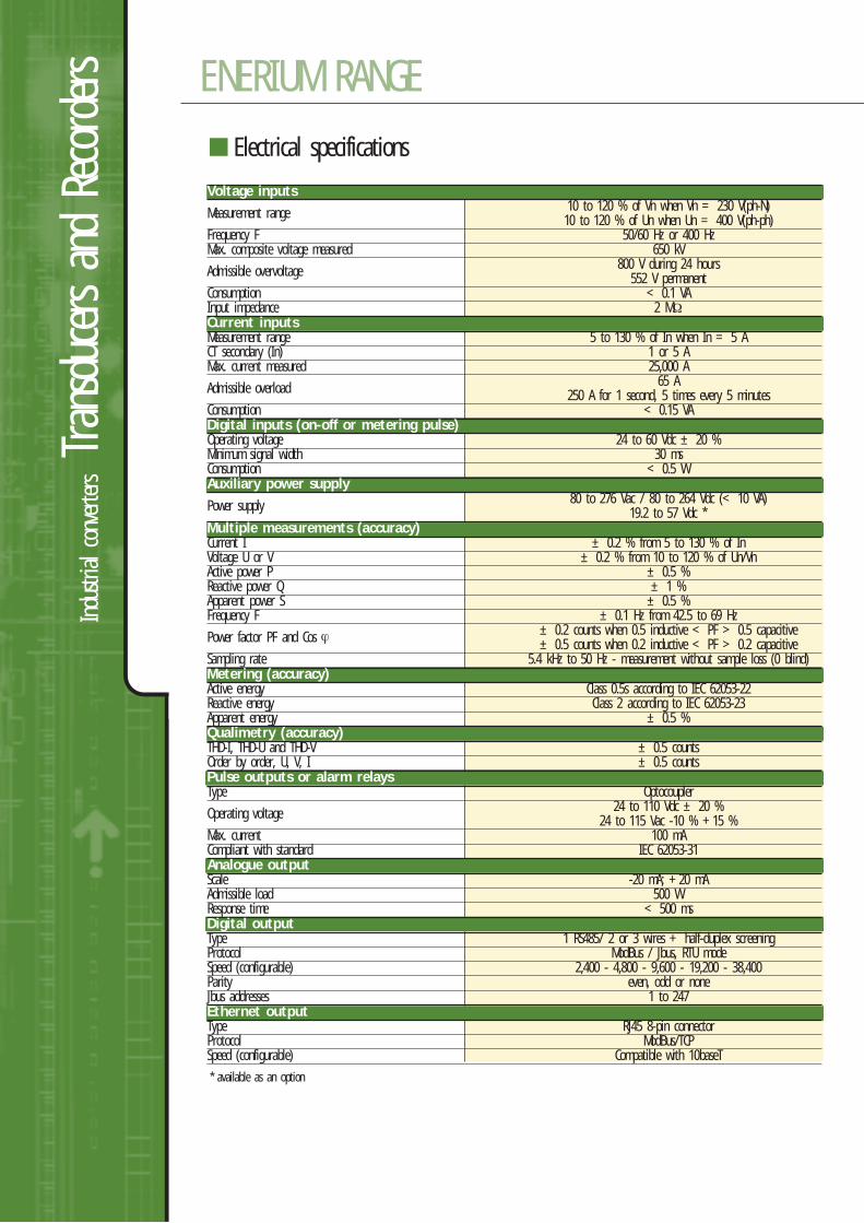
Industrial
converter
sTran
sducers an
d Re
corders
Voltage inputs
Measurement range 10 to 120 % of Vn when Vn = 230 V(ph-N)10 to 120 % of Un when Un = 400 V(ph-ph)
Frequency F 50/60 Hz or 400 HzMax. composite voltage measured 650 kV
Admissible overvoltage 800 V during 24 hours552 V permanent
Consumption < 0.1 VAInput impedance 2 MΩCurrent inputsMeasurement range 5 to 130 % of In when In = 5 ACT secondary (In) 1 or 5 AMax. current measured 25,000 A
Admissible overload 65 A250 A for 1 second, 5 times every 5 minutes
Consumption < 0.15 VADigital inputs (on-off or metering pulse)Operating voltage 24 to 60 Vdc ± 20 %Minimum signal width 30 msConsumption < 0.5 WAuxiliary power supply
Power supply 80 to 276 Vac / 80 to 264 Vdc (< 10 VA)19.2 to 57 Vdc *
Multiple measurements (accuracy)Current I ± 0.2 % from 5 to 130 % of InVoltage U or V ± 0.2 % from 10 to 120 % of Un/VnActive power P ± 0.5 %Reactive power Q ± 1 %Apparent power S ± 0.5 %Frequency F ± 0.1 Hz from 42.5 to 69 Hz
Power factor PF and Cos ϕ ± 0.2 counts when 0.5 inductive < PF > 0.5 capacitive± 0.5 counts when 0.2 inductive < PF > 0.2 capacitive
Sampling rate 5.4 kHz to 50 Hz - measurement without sample loss (0 blind)Metering (accuracy)Active energy Class 0.5s according to IEC 62053-22Reactive energy Class 2 according to IEC 62053-23Apparent energy ± 0.5 %Qualimetry (accuracy)THD-I, THD-U and THD-V ± 0.5 countsOrder by order, U, V, I ± 0.5 countsPulse outputs or alarm relaysType Optocoupler
Operating voltage 24 to 110 Vdc ± 20 %24 to 115 Vac -10 % +15 %
Max. current 100 mACompliant with standard IEC 62053-31Analogue outputScale -20 mA; +20 mAAdmissible load 500 WResponse time < 500 msDigital outputType 1 RS485/ 2 or 3 wires + half-duplex screeningProtocol ModBus / Jbus, RTU modeSpeed (configurable) 2,400 - 4,800 - 9,600 - 19,200 - 38,400Parity even, odd or noneJbus addresses 1 to 247Ethernet outputType RJ45 8-pin connectorProtocol ModBus/TCPSpeed (configurable) Compatible with 10baseT
* available as an option
Electrical specifications
ENERIUM RANGE
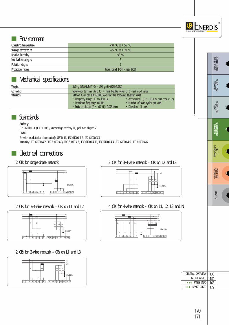
3
4
5
6
ENER
GY M
ETER
S PO
WER
MON
ITORS
ANAL
OGUE
PA
NEL
METE
RSDIGITA
L PA
NEL
METE
RSTR
ANSD
UCER
SAN
D RE
CORD
ERS
TRAN
SFOR
MERS
SHUN
TSCO
NTRO
LLING
AND
RELA
YS
7
APPE
NDIX
2
1
Mechanical specificationsWeight 850 g (ENERIUM 110) - 700 g (ENERIUM 210)Connection Screw-lock terminal strip for 4 mm2 flexible wires or 6 mm2 rigid wiresVibration Method A as per IEC 600068-2-6 for the following severity levels:
• Frequency range: 10 to 150 Hz • Acceleration (F < 60 Hz): 9.8 m/s2 (1 g)• Transition frequency: 60 Hz • Number of scan cycles per axis• Peak amplitude: (F < 60 Hz): 0.075 mm • Direction : 3 axes
EnvironmentOperating temperature -10 °C to +55 °CStorage temperature -25 °C to +70 °CRelative humidity 95 %Installation category 3Pollution degree 2Protection rating Front panel IP51 - rear IP20
Electrical connections
StandardsSafetyCE: EN61010-1 (IEC 1010-1), overvoltage category III, pollution degree 2
EMCEmission (radiated and conducted): CISPR 11, IEC 61000-3-2, IEC 61000-3-3Immunity: IEC 61000-4-2, IEC 61000-4-3, IEC 61000-4-8, IEC 61000-4-11, IEC 61000-4-4, IEC 61000-4-5, IEC 61000-4-6
I1 I2
1 2 3 4 5 6 7 8
L1L2L3
V1 V2 V3
10 11 12 13 14 15 169
Supply
1
I1 V1 V2 V3
2 3 4 5 6 7 8 9 10 11 12 13 14
L1L2L3
15 16
I3
Supply
1 2 3 4 5 6 7 8
L1L2L3
I2 I3 V1 V2 V3
9 10 11 12 13 14 15 16
Supply
2 CTs for 3/4-wire network - CTs on L1 and L2
2 CTs for 3-wire network - CTs on L1 and L3
2 CTs for single-phase network
1
I1 I2 V1 V2 V3
2 3 4 5 6 7 8 9 10 11 12 13 14
L1L2L3N
15 16
In I3
Supply
2 CTs for 3/4-wire network - CTs on L2 and L3
4 CTs for 4-wire network - CTs on L1, L2, L3 and N
1
In V1
2 3 4 5 6 7 8 9 10 11 12 13 14
L1N
15 16
Supply
I1
170171
GENERAL OVERVIEWINFO & ADVICE
RANGE INFO RANGE CONTD
130134168172
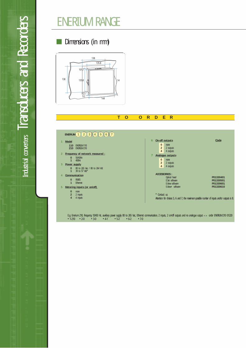
Industrial
converter
sTran
sducers an
d Re
corders
Dimensions (in mm)
1449.2
92.5
101.7
138
135.8
135.8138 144
ENERIUM 1 2 3 4 5 6 7
1 Model110 ENERIUM 110210 ENERIUM 210
2 Frequency of network measured :0 50/60Hz1 400Hz
3 Power supply0 80 to 265 Vac / 80 to 264 Vdc1 39 to 57 Vdc*
4 Communication
0 RS4851 Ethernet
5 Metering inputs (or on/off)
0 none2 2 inputs4 4 inputs
6 On-off outputs Code0 none2 2 outputs4 4 outputs
7 Analogue outputs
0 none2 2 outputs4 4 outputs
ACCESSORIES :Optical head P01330401E.Set software P01330501E.View software P01330601E.View+ software P01330610
* Contact usAttention: for choices 5, 6 and 7, the maximum possible number of inputs and/or outputs is 8.
T O O R D E R
E.g. Enerium 210, frequency 50/60 Hz, auxiliary power supply 80 to 265 Vac, Ethernet communication, 2 inputs, 2 on/off outputs and no analogue output => order ENERIUM 210 01220• 1-210 • 2-0 • 3-0 • 4-1 • 5-2 • 6-2 • 7-0
ENERIUM RANGE
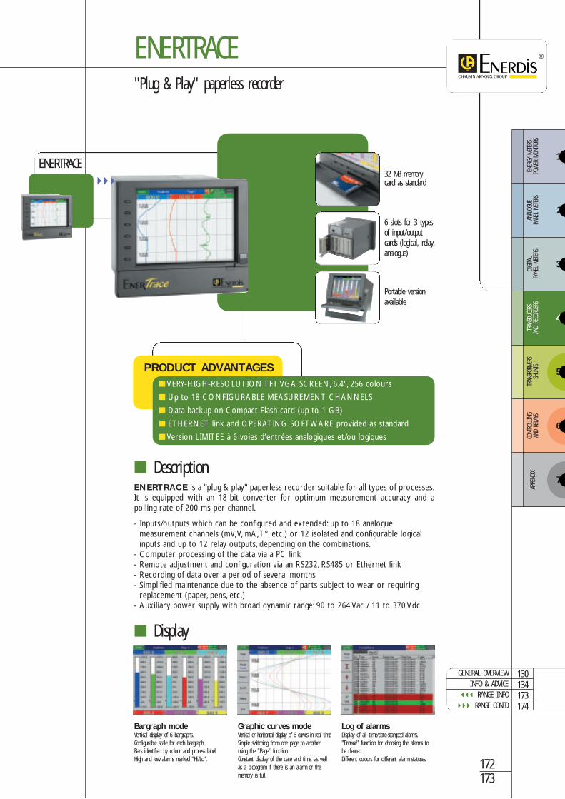
3
4
5
6
ENER
GY M
ETER
S PO
WER
MON
ITORS
ANAL
OGUE
PA
NEL
METE
RSDIGITA
L PA
NEL
METE
RSTR
ANSD
UCER
SAN
D RE
CORD
ERS
TRAN
SFOR
MERS
SHUN
TSCO
NTRO
LLING
AND
RELA
YS
7
APPE
NDIX
2
1
172173
GENERAL OVERVIEWINFO & ADVICE
RANGE INFO RANGE CONTD
130134173174
ENERTRACE"Plug & Play" paperless recorder
ENERTRACE is a "plug & play" paperless recorder suitable for all types of processes.It is equipped with an 18-bit converter for optimum measurement accuracy and apolling rate of 200 ms per channel.
- Inputs/outputs which can be configured and extended: up to 18 analoguemeasurement channels (mV,V, mA,T°, etc.) or 12 isolated and configurable logicalinputs and up to 12 relay outputs, depending on the combinations.
- Computer processing of the data via a PC link- Remote adjustment and configuration via an RS232, RS485 or Ethernet link- Recording of data over a period of several months- Simplified maintenance due to the absence of parts subject to wear or requiring
replacement (paper, pens, etc.)- Auxiliary power supply with broad dynamic range: 90 to 264 Vac / 11 to 370 Vdc
32 MB memorycard as standard
6 slots for 3 typesof input/outputcards (logical, relay,analogue)
Portable versionavailable
Description
PRODUCT ADVANTAGES VERY-HIGH-RESOLUTION TFT VGA SCREEN, 6.4", 256 colours
Up to 18 CONFIGURABLE MEASUREMENT CHANNELS
Data backup on Compact Flash card (up to 1 GB)
ETHERNET link and OPERATING SOFTWARE provided as standard
Version LIMITEE à 6 voies d’entrées analogiques et/ou logiques
ENERTRACE
Bargraph modeVertical display of 6 bargraphs.Configurable scale for each bargraph.Bars identified by colour and process label.High and low alarms marked "Hi/Lo".
Graphic curves modeVertical or horizontal display of 6 curves in real timeSimple switching from one page to anotherusing the "Page" functionConstant display of the date and time, as wellas a pictogram if there is an alarm or thememory is full.
Log of alarmsDisplay of all time/date-stamped alarms."Browse" function for choosing the alarms tobe cleared.Different colours for different alarm statuses.
Display
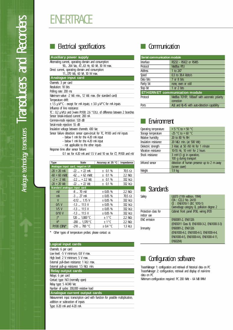
Analo
gue
techn
ology transdu
cersTran
sducers an
d Re
corders
Auxiliary power supplyAlternating current, operating domain and consumption:
90... 264 Vac, 47...63 Hz, 60 VA, 30 W max.Direct current, operating domain and consumption:
11...370 Vdc, 60 VA, 30 W max.Analogue input cardChannels: 3 per cardResolution: 18 bitsPolling rate: 200 msMaximum value: -2 Vdc min., 12 Vdc max. (for standard card)Temperature drift:±1.5 µV/°C - except for mA inputs; ±3.0 µV/°C for mA inputsInfluence of line resistance:TC : 0.2 µV/Ω and 3-wire Pt100: 2.6 °C/Ω. of difference between 2 branchesSensor break-induced current: 200 nACommon-mode rejection: 120 dBSerial-mode rejection: 55 dBInsulation voltage between channels: 430 VacSensor failure detection: sensor open-circuit for TC, Pt100 and mV inputs
- below 1 mA for the 4-20 mA input- below 1 mA for the 4-20 mA input- not applicable to the other inputs
Response time after sensor failure:0.1 sec for 4-20 mA and 1.5 V and 10 sec for CT, Pt100 and mV
* Other types of temperature probes: please contact us
Electrical specifications
EnvironmentOperating temperature +5 °C to +50 °CStorage temperature -25 °C to +60 °CRelative humidity 20 to 80 % RHInsulation resistance 20 MΩ min. (at 500 Vdc)Dielectric strength 3 kVac at 50 /60 Hz for 1 minuteVibration resistance 10-55 Hz, 10 m/s2 for 2 hoursShock resistance 3 m/s2 (3 g) in operation,
100 g during transportInfrared sensor detection of human presence up to 2 m away
(screen saver)Weight 1.9 kg
StandardsSafety UL873 (11th edition, 1994)
CSA : C22.2 No. 24-93CE : EN61010-1 (IEC 1010-1) Overvoltage category II, pollution degree 2
Protection class for Cabinet front panel IP30, wiring IP20indoor useEMC emission EN50081-2, EN61326
(EN55011 Class B, EN61000-3-2, EN61000-3-3)Immunity EN50081-2, EN61326
(EN61000-4-2, EN61000-4-3, EN61000-4-4, EN61000-4-5, EN61000-4-6, EN61000-4-11, EN50204)
Configuration softwareTracerManager 1: configuration and retrieval of historical data on PCTracerManager 2: configuration, retrieval and display of real-timedata on PCMinimum configuration required: PC 200 MHz - 64 MB RAM
CommunicationSerial communication module
Interface RS232 - RS422 or RS485Protocol ModBus RTUAddress 1 to 247Speed 0.3 to 38.4 kbits/sData bits 7 or 8 bitsParity bit none, even or oddStop bit 1 or 2 bitsETHERNET communication moduleProtocol ModBus TCP/IP, 10BaseT with automatic polarity
correctionPorts AUI and RJ-45 with auto-detection capability
NLogical input cardsChannels: 6 per cardLow level: -5 V minimum, 0.8 V max.High level: 2 V minimum, 5 V max.External pull-down resistance: 1 kΩ max.External pull-up resistance: 1.5 MΩ min.Relay output cardsRelays: 6 per cardContact type: N.O (normally open)Relay type: 5 A/240 VacNumber of cycles: 200,000 resistive loadAnalogue current output cardsMeasurement input transcription card with function for possible multiplication,addition or subtraction of inputsType: 0-20 mA and 4-20 mA
Type Scale Accuracy at 25 °C ImpedanceAnalogue input card, negative U/I
-20 +20 mA -22 ... +22 mA ± 0.1 % 70.5 Ω-60 +60 mVdc -62 ... +62 mVdc ± 0.1 % 2.2 MΩ-2 + 2 Vdc -2.2 ... +2.2 Vdc ± 0.1 % 332 kΩ
-20 +20 Vdc -22 ... +22 Vdc ± 0.1 % 332 kΩStandard analogue input card
mV -8 ... 70 mV ±0.05 % 2.2 MΩmA -3 ... 27 mA ±0.05 % 70.5 ΩV -0.12 ... 1.15 V ±0.05 % 332 kΩ
0/5 V -1.3 ... 11.5 V ±0.05 % 332 kΩ1/5 V -1.3 ... 11.5 V ±0.05 % 332 kΩ0/10 V -1.3 ... 11.5 V ±0.05 % 332 kΩJ* 120 ... 1,000 °C ±1 °C 2.2 MΩK* -200 ... 1,370 °C ±1 °C 2.2 MΩ
Pt100 (DIN)* -210 ... 700 °C ±0.4 °C 1.3 kΩ
ENERTRACE
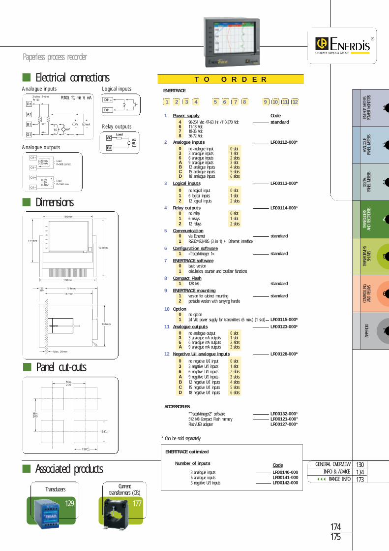
3
4
5
6
ENER
GY M
ETER
S PO
WER
MON
ITORS
ANAL
OGUE
PA
NEL
METE
RSDIGITA
L PA
NEL
METE
RSTR
ANSD
UCER
SAN
D RE
CORD
ERS
TRAN
SFOR
MERS
SHUN
TSCO
NTRO
LLING
AND
RELA
YS
7
APPE
NDIX
2
1
174175
Paperless process recorder
ENERTRACE
1 2 3 4 5 6 7 8 9 10 11 12
1 Power supply Code4 90-264 Vac 47-63 Hz /110-370 Vdc ------------------- standard6 11-18 Vdc7 18-36 Vdc8 36-72 Vdc
2 Analogue inputs ------------------- LR00112-000*0 no analogue input 0 slot3 3 analogue inputs 1 slot6 6 analogue inputs 2 slotsA 9 analogue inputs 3 slotB 12 analogue inputs 4 slotsC 15 analogue inputs 5 slotsD 18 analogue inputs 6 slots
3 Logical inputs ------------------- LR00113-000* 0 no logical input 0 slot1 6 logical inputs 1 slot2 12 logical inputs 2 slots
4 Relay outputs ------------------- LR00114-000* 0 no relay 0 slot1 6 relays 1 slot2 12 relays 2 slots
5 Communication0 via Ethernet ------------------- standard1 RS232/422/485 (3 in 1) + Ethernet interface
6 Configuration software1 «TracerManager 1» ------------------- standard
7 ENERTRACE software0 basic version1 calculation, counter and totalizer functions
8 Compact Flash1 128 Mo ------------------- standard
9 ENERTRACE mounting1 version for cabinet mounting ------------------- standard2 portable version with carrying handle
10 Option0 no option1 24 Vdc power supply for transmitters (6 max.) [1 slot]---- LR00115-000*
11 Analogue outputs ------------------- LR00123-000*0 no analogue output 0 slot3 3 analogue mA outputs 1 slot6 6 analogue mA outputs 2 slotsA 9 analogue mA outputs 3 slots
12 Negative U/I analogue inputsi ------------------- LR00128-000*0 no negative U/I input 0 slot3 3 negative U/I inputs 1 slot6 6 negative U/I inputs 2 slotsA 9 negative U/I inputs 3 slotsB 12 negative U/I inputs 4 slotsC 15 negative U/I inputs 5 slotsD 18 negative U/I inputs 6 slots
ACCESSORIES:
"TracerManager2" software ------------------- LR00132-000*512 MB Compact Flash memory ------------------- LR00121-000*Flash/USB adapter ------------------- LR00127-000*
* Can be sold separately
T O O R D E R
177
Currenttransformers (CTs)
Associated products
Electrical connections
Dimensions
Panel cut-outs
129
Transducers
Analogue inputs
Analogue outputs
Logical inputs
Relay outputs
Pt100, TC, mV, V, mA
AC
B1
ACorCC
Load
ENERTRACE optimized
Number of inputs Code3 analogue inputs ------------------- LR00140-0006 analogue inputs ------------------- LR00141-0003 negative U/I inputs ------------------- LR00142-000
130134173
GENERAL OVERVIEWINFO & ADVICE
RANGE INFO

Notes
& com
ments
Top Related