


Languages
Pages
Legal


NORTH REGION OFFICE OF SURVEYS QUALITY MANAGEMENT PLAN FOR SURVEYS INDEX:
1. MISSION STATEMENT FOR NROS-SURVEYS, QMP. 2. QC/QA DESIGN BASED FLOWCHART FOR SURVEYS 3. QC-QA FLOWCHART OUTLINE 4. “COMBINED SURVEYS AND R/W ENGINEERING PROJECT WORK FLOW DIAGRAM”, (THIS IS A DETAILED FLOW CHART OF THE INTERACTION OF SURVEYS AND R/W ENGINEERING WITH THE PROJECT). 5. GENERAL GUIDELINES FOR DESIGN FIELD SURVEYS 6. FIELD BOOK PREPARATION 7. REPORT OF FIELD SURVEY 8. PROCESSING THE SURVEY REQUEST 9. SURVEY FILE CHECKLIST
9A. CONSTRUCTION/SURVEYS EXPECTATIONS

NORTH REGION OFFICE OF SURVEYS: QUALITY MANAGEMENT PLAN The NORTH REGION OFFICE OF SURVEYS (NROS) is a product and customer satisfaction driven division. In its efforts to attain a high level of quality assurance it finds its quality control elements bound to the integrity of its employees, who initiate and maintain the quality of the product, the SURVEYS MANUAL1, the laws embodied in the CALIFORNIA LAND SURVEYORS ACT and SUBDIVISION MAP ACT, and its internal processes built with redundancies and checklists from field surveys through office processing. GENERAL GUIDELINES FOR QUALITY CONTROL AND QUALITY ASSURANCE (QC/QA) In broad scope, the NROS QC/QA program aims to ensure the following: • That each task complies with the laws and regulations that govern the use of Federal, State, and local transportation funds; • That each product meets the customer’s needs and purposes, as defined in the Task Order and Cost Estimate; • That a process for constructive feedback is implemented and contributes to satisfactory product delivery; • And, that immunities established by law to protect the Department and its employees from liability are preserved. These guidelines apply to all Survey Tasks including participation in the preparation of the Project Initiation Document (PID); engineering and environmental studies; plans, specifications and estimates; right of way, and construction to project closeout. As with any general guidelines, which must apply to a wide range of activities, NROS staff members are expected to use professional judgment in their application. In its conception, QC/QA is not intended to be an additional layer of effort required to deliver a successful project. It is, simply or not, intended to be the norm that governs all activities, projects, and processes within NROS. The more specific steps towards Quality Assurance, through Quality Control, are described, listed and appended below. 1 The SURVEYS MANUAL can be found at: http://www.dot.ca.gov/hq/esc/geometronics/SurveysManual. It is continually updated as processes and technology change.

IMPLEMENTING QUALITY ASSURANCE The policies and processes of NROS are developed and continually refined to ensure high quality in its project deliverables through a series of Quality Control measures. These policies and processes are applied throughout the product delivery process from project initiation to post-construction. These measures include, but are not limited to, the following: • A well trained and experienced work force, which is dedicated to producing a high quality product; • The SURVEYS MANUAL, which specifies the precision, quality, and accuracy of the survey and its attendant documents throughout the range of NROS’ many tasks; • The office preparation, field surveys, and office processing practices with their many quality control checkpoints2; • Feedback from the customers, including the other CALTRANS divisions and the public; • Monthly field and office personnel meetings with Senior level participation to critique and improve current practices. The more specific steps to Quality Assurance through Quality Control are contained in NROS and Departmental checklists and flowcharts, of which the pertinent ones are described and appended below. APPENDED CHECKLISTS AND ASSOCIATED DOCUMENTS The following documents are appended:
1. “QC/QA DESIGN BASED FLOWCHART FOR SURVEYS”, which is the base flowchart document for the QMP
2. “QC-QA FLOWCHART OUTLINE”, which is an outline of the materials within the QC/QA Flowchart (“1” above).
3. “COMBINED SURVEYS AND R/W ENGINEERING PROJECT WORK FLOW DIAGRAM”, which is a complex flow chart diagramming the interactions of Surveys and R/W Engineering from project inception to completion (post construction and monument and control maintenance activities).
4. “GENERAL GUIDELINES FOR DESIGN FIELD SURVEYS”, which is a descriptive document of field survey procedures.
5. “FIELD BOOK PREPARATION”, which is a checklist of procedures for preparing the SR for the Survey Field Crew.
6. “OFFICE TO FIELD: REPORT OF FIELD SURVEY”, which is a checklist for topographic surveys, or TLI, for field crews.
2 The checkpoints are defined by the checklists and job flow charts appended to this document.

7. “PROCESSLING THE SURVEY REQUEST”, which is a checklist for preparing the field survey for the Requestor.
8. “SURVEY FILE CHECKLIST”, which is a checklist and guideline of needed elements of the “Survey File” from field to design to construction.
9. “CONSTRUCTION/SURVEYS EXPECTATIONS”, which is a listing of the “Expectations and Performance Measures of PS&E Customers” and serves as a general guideline for construction project procedures and consultant project procedures.

QUA ITY MANAGEMENT PLAN T SPE FIC QUALITY CONTROL PLAN-
QUALITY CONTROL TOOLS
ADV PHASE
CONST PHASE
RTL PHASE (Continue 185,200,255 Activities
SE 150)
A&ED PHASE
TIO
N
iver
y
PID
tanc
e
ENTS
ENCE
SU160
REVIE PHASE PR
DRAFT PS &BS “1”- 185,1
SR Preparation: • Preparation of SR (survey request) in accordance with Department policies as stated and listed in the SURVEYS MANUAL
eometronics/SurveysManual/). IEL
expethin tSURfice cheare th
nt Team/PDT (150,160.15,
of Survey
•Establish Datum(160.20,185.10) •TSS/TLI (150.05.30,160.20,185.10 •Aerial Mapping/Photogrammetry (160.20,185.10) •Vangarde (185.10) •Bridge Site Submittal (190,210,185.10) •Utility/Potholing (“2” phase, 200.10) •R/W Monumentation & Boundary (300.05)
Assess Resource needs
s Departmental procedures soned SURVEYS MANUAL
NROS, DISTRICT 03: PROCESSING THE SURVEY REQUEST checklist (appended). • Processing (the SR) checklist • SR sent to Requestor, managers notified • Archive the project to the “Project” drive and• SR processing is the same in all phases.
nit needs for Surveys ) (150.05,160.05,185.05) ey Crew (ongoing all phases (210) Control Needs (160.20,185.
ith Functional Units (unde
vey Data
• Deliver Surveys to Functional Unit (185.10) • Follow-up with Functional Units
• Field Crew Performs• SR assigned to Proce• Processor prepares S and coordinates, as ne Requestor. • SR delivered to Requ Project Manager, Offi And others notified.
• Office Senior Fieldbook Pre• Area Field Se Survey Crew P• Party Chief co Requestor.
Task Manager attends to PDT needs: i.e. attendance at, or conference with the PDT members to determine Survey needs (usually determined by scope of the SR). • Seniors and Task Manager coordinate funding with Project Management Liaison.
TASK MANAGEMENT
LCI
(WBS “3”- 270,285; WBS “2”- 300)
as appropriate)
RT
L C
ER
TIF
ICA
Fun
ctio
nal U
nit D
el
PA&
ED
Proj
ect A
ccep
W RTL CONSTRUCTION SURVEY
d 3/04/200 Last Revise
Staking: • Construction Staking is performed with reference to the specifics of: • “Construction Surveys” (Chap 12 of SURVEYS MANUAL). • CALTRANS most current STANDARD PLANS
Monumentation: • Post Construction, Right of Way Engineering directed for Record of Survey And within SURVEYS MANUAL and The LAND SURVEYOR’S ACT.
• Review and enact staking requests in conference with the Project Engineer (PE), Inspectors, and Contractor(s). (“3” phase 270.10,270.15) • Check to see that the design fits: field design or return to Design, if necessary (270) • Review and enact construction change orders/CCO’s (285.10) • R/W Monumentation (“2” Phase, 300.05)
ODUCT
• Review Project plans/X-sections/staking notes (255.35) • Participate in Constructability Reviews (255) • Follow up with Functional Units
CERTIFICATION
et down and
to CD.
s)
10)
r SR: 160,185, etc.).
• PDT pre-circulation review • Phase Specific Product Review • Resolve Comments • Update Project Specific QMP
CONSTRUCTION: • Party Chief performs Staking Requests from PE and Inspectors by Contractors. • Party Chief communicates staking needs to Design. • Party Chief checks staking against the design. • Party Chief stakes change orders (CCO’s). • Party Chief delivers staking notes and/or summaries to PE.
RTL: • Office Senior assigns Design Construction Processing to Processor (may occur in previous phases to allow communication with PDT). • Area Field Senior assigns Party Chief to Project (may be done in Design Phase). • Processor prepares staking notes in communication with Design assigned Party Chief and Area Field Senior.
Survey ssor R for Design eded, with
estor and ce Senior
Tools and Checklists: • SURVEYS MANUAL • State LAND SURVEYOR’S ACT • General Guidelines for Design Field Surveys • Field Book Preparation checklist • Report of Field Survey checklist • Processing the Survey Request checklist • Survey File Checklist (for construction) • Caltrans Quality Management Program PS&E Workgroup for PS&E Customers. •All are appended within the Surveys QMP, except the Manual and Act.
TASKS: 270, 285, 300
Revised 10/11/05
PID PHA (WBS “K”-
P
Project ID
QUALITY MILESTONES
QUALITY CONTROL ELEM
PDTCONCURR 150
(W
Participate in Project Developme 185.05)
Recommend Appropriate Levels and Mapping:
NORTH REGION-SURVEYS PROJEC
(WBS “0” -160,165,180,205,210)
BEGIN RVEY TASKS , 185, 200, 220
COMPLETE SURVEY TASKS 185, 200, 255 et al
E PHASE 90,210,235,255)
• Field & Office Verification of Sur (160.20,185.10)
SR Processing: • Processing follow in the aforementi
• Coordinate Functional U• Review Survey Request(s• Evaluate Safety for Surv• Review BSS survey need• Assess Corridor/Project • Select Survey Crew • Office/Field Follow-up w
assigns SR to parer/Processor. nior assigns SR to arty Chief. nfers with Design
( http://www.dot.ca.gov/hq/esc/g• Preparation also in reference to: F checklist (appended). • Select Field Survey Crew(s) for• Field Crews perform surveys wi MANUAL and the State LAND • Field preparation of the SR for of REPORT OF FIELD SURVEY• SR preparation and field surveys
D BOOK PREPARATION
rtise. he procedures of the SURVEYS VEYOR’S ACT. processing follows the cklist (appended). e same in all phases.

NORTH REGION OFFICE OF SURVEYS QUALITY MANAGEMENT PLAN (QMP) RE: DESIGN QC/QA PLAN-SURVEYS-FLOWCHART (An outline/elaboration of the flowchart) Of note: The flowchart is designed to meet Design’s needs, as the Project directing body. Surveys has found some plasticity in the row definitions or headings as they apply to the services we provide. Sometimes a “Quality Control Element” and a “Quality Control Tool” are interchangeable. In the process of surveying, as in the other divisions, there are constant checks built into the procedures employed by the surveyors, and they, the surveyors, are the most important “Quality Control Element”, and their “tools” are the knowledge and understanding of the processes needed for good design. Too, our processes tend to be responses of a service division to a Survey Request and are much the same throughout the Project flow. PROJECT INITIATION DOCUMENT (PID), PROJECT APPROVAL AND ENVIRONMENTAL DOCUMENTS (PA&ED), AND DESIGN PHASES:
1. Surveys involvement with a Design Project begins with the PDT meetings leading up to PDT Concurrence.
2. Seniors and Project Management Liaison review budgeting needs for Project.
3. Project specific work begins with the Survey Request, or SR, being received from another functional unit, usually Design.
4. The preparation of the SR for field survey is the same in all phases and occurs in “K” phase through construction, and, on occasion, post-construction with a monumentation request from Right of Way Engineering.
5. The project or SR is assessed on arrival for specific survey needs which can include: area control needs (the vertical and horizontal datum and monumentation), the type of survey that best fits the request (TSS/TLI, Photogrammetry, Vangarde), whether it is a Bridge Site Submittal (BSS), what utility location may be needed (potholing), and whether any R/W location and monumentation is needed
6. Processing the field survey for the Requestor is also the same in all phases. It begins with the return of the survey from the field. It is processed or edited on the current department software, and the product is delivered to the Requestor with any needed explanations and/or accompanying data. The current deliverables are the processed/edited
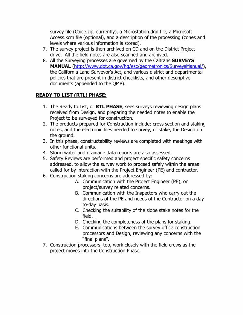
survey file (Caice.zip, currently), a Microstation.dgn file, a Microsoft Access.kcm file (optional), and a description of the processing (zones and levels where various information is stored).
7. The survey project is then archived on CD and on the District Project drive. All the field notes are also scanned and archived.
8. All the Surveying processes are governed by the Caltrans SURVEYS MANUAL (http://www.dot.ca.gov/hq/esc/geometronics/SurveysManual/), the California Land Surveyor’s Act, and various district and departmental policies that are present in district checklists, and other descriptive documents (appended to the QMP).
READY TO LIST (RTL) PHASE:
1. The Ready to List, or RTL PHASE, sees surveys reviewing design plans received from Design, and preparing the needed notes to enable the Project to be surveyed for construction.
2. The products prepared for Construction include: cross section and staking notes, and the electronic files needed to survey, or stake, the Design on the ground.
3. In this phase, constructability reviews are completed with meetings with other functional units.
4. Storm water and drainage data reports are also assessed. 5. Safety Reviews are performed and project specific safety concerns
addressed, to allow the survey work to proceed safely within the areas called for by interaction with the Project Engineer (PE) and contractor.
6. Construction staking concerns are addressed by: A. Communication with the Project Engineer (PE), on
project/survey related concerns. B. Communication with the Inspectors who carry out the
directions of the PE and needs of the Contractor on a day-to-day basis.
C. Checking the suitability of the slope stake notes for the field.
D. Checking the completeness of the plans for staking. E. Communications between the survey office construction
processors and Design, reviewing any concerns with the “final plans”.
7. Construction processors, too, work closely with the field crews as the project moves into the Construction Phase.

CONSTRUCTION PHASE: The Construction Phase consists of the following processes and practices:
1. Meetings with PE, Inspectors and contractors addressing the project staking needs, and the scheduling of staking requests (request flow: Contractor to PE/Inspector to Field Crew Party Chief).
2. Construction staking is performed within the standards defined in the SURVEYS MANUAL, and within agreements with the Project Engineer(s), Inspector(s), and contractors.
3. Field crew and office construction processors communicate and interact with the “final” design plans, design engineers, PE & Inspectors, and Contractor to fulfill staking requests.
4. In the process of staking, the Project Surveyor checks to see that the field staking fits the design requirements and fit with the existing ground and structures (a continuing process throughout staking), and noting if area re-designs are needed.
5. The field crew finalizes the staking, finishing staking requests, and any construction change orders (CCO’s) approved by the PE/Inspector/Contractor interaction.
POST-CONSTRUCTION PHASE: The Post-Construction Phase essentially involves Surveys in monumenting the “new” right of way and establishing any needed land net monuments required by the scope of the project. Such requests usually come from Right of Way Engineering, or Right of Way, and in some cases can be a decade or two from the end of construction or the abandonment of a project. Such work usually consists of:
1. Right of Way Engineering requests monumentation of the Right of Way (R/W).
2. Project Control is refurbished and construction losses are replaced in contemplation of future road maintenance and construction concerns.


Caltrans North Region Office of Surveyors Marysville Office
General Guidelines for Design Field Surveys The purpose of this document is to standardize the way in which NROS field surveys for
design are accomplished, and to provide for better coordination between the various elements of
those surveys. In addition to the work accomplished by the field crews, design surveys may
include support from vangarde, photogrammetry, and GPS. The manner in which each function
is accomplished directly effects the various other functions and ultimately the project
deliverables.
These guidelines are not cast in stone, but should be adhered to unless circumstances
dictate otherwise. Any deviance from the suggested procedures must be coordinated in advance
with the Field Chief so that he can insure that all parties are aware of the change.
Project Overview
Site Evaluation The first function to arrive onsite will be the field crew. Initially, their job will be to
uncover the existing control net and to determine the limits of the project. Additionally, they
will need to search for and recover a number of right - of - way monuments sufficient to
generally locate the bounds of the project area for design purposes. This doesn’t mean that every
monument needs to be located. Generally, if monuments can be uncovered at the ends of the
project, with a few thrown in somewhere in the middle, a rough boundary analysis can be
accomplished.
Once the existing control and right - of - way has been recovered, the party chief
analyzes the site to determine if supplemental control is required. In cases where ‘83 control is
not available, GPS static control will need to be brought in to control the site. (Note that for the
purposes of this document, static and fast static GPS will be lumped together as “static.”) It is
also a good idea to tie any existing ‘27 control into the ‘83 net so as-built drawings and
monument maps can be used in conjunction with the new design data. Party chiefs must beware
of using any found GPS control until they have verified that it was brought in by static means.
RTK is not suitable for precise control and will result in significant error propagation if
improperly utilized.
1

Caltrans North Region Office of Surveyors Marysville Office
When considering the project’s control needs, the party chief should also look to future
needs, remembering that some or all of his control may be useful during construction. He is also
charged with densifying Caltran’s existing primary control net. Ideally, primary control (brass
disks in concrete, GPS statically controlled) should be spaced at about one mile intervals
throughout the project. If practical, primary control should also be elevated to at least second
order, class II specifications, by three - wire or digital leveling. The GPS Coordinator should be
consulted with prior to the placement of any control requiring static GPS.
Photogrammetry If the project is to be flown, premarks need to be laid out on the main line(s) at 450-foot
intervals for high flight, or 250-foot intervals for PTL. These targets are in addition to the HV
and V points shown on the photogrammetry control plan. Mainline HV and V points should be
tied into a comprehensive control net, not just “hung” on some nearby GPS control or bench.
Unless this procedure is followed, the next party onsite will have to run control before they can
finish their job. Remember, the purpose of static GPS is to provide conventional control traverse
endpoints.
Premarks must be set out as soon as practical so that the project can be flown at the
earliest possible date. Photogrammetry is the longest process in the design deliverables package
so we need to expedite our portion of it. Once the project has been flown it is ready to be
controlled.
Conventional supplemental control needs to be run from one end of the project to the
other, in such a manner as to support TLI collection and if possible, future construction needs.
All of the HV, V, and intermediate premarks (450’s) on the mainline need to be elevated,
preferably by differential levels, to second order, class II standards. Second order, class II
specifications can be met with trig leveling procedures (see attachment). For projects utilizing
PTL, all HV, V, and mainline intermediate premarks (250’s) must be elevated by digital level to
apparent first order, second class specifications. High flight wing points can be trig leveled, but
should be double tied to prevent blunders.
On projects where RTK is utilized to locate premarks, it should only be used on the wing
points for elevation. The mainline must be elevated conventionally to minimize error in the
pavement planes. RTK can also be used to tie found right - of - way monuments. All RTK
2

Caltrans North Region Office of Surveyors Marysville Office
coordinates sheets must be clearly marked to indicate RTK positioning was used in order to
prevent confusing future surveyors regarding the precision of the data.
Vangarde In cases where vangarde is not following photogrammetry on the project, they will need
to have horizontal and vertical project control spaced at no less than 1000-foot intervals. In
cases where vangarde follows photogrammetry, the existing control scheme will be sufficient for
their needs.
Vangarde will be responsible for the collection of pavement planes and any topographic
information lying in harm’s way. Additionally, they may be called upon to collect drainage
structures, etc. on smaller projects or projects where the scope of work doesn’t warrant
conventional TLI methods.
TLI In addition to controlling the project and providing support for photogrammetry and
vangarde, field crews will be responsible for all TLI collection not accomplished by other means.
All topographic features not clearly discernible from aerial photos (power poles, pull boxes, etc.)
and all drainage (submersed flowlines, inverts, etc.) are the responsibility of the field crews. In
areas where safety is not a problem, field crews may also be responsible for topographic and
DTM features normally captured by vangarde or PTL.
3
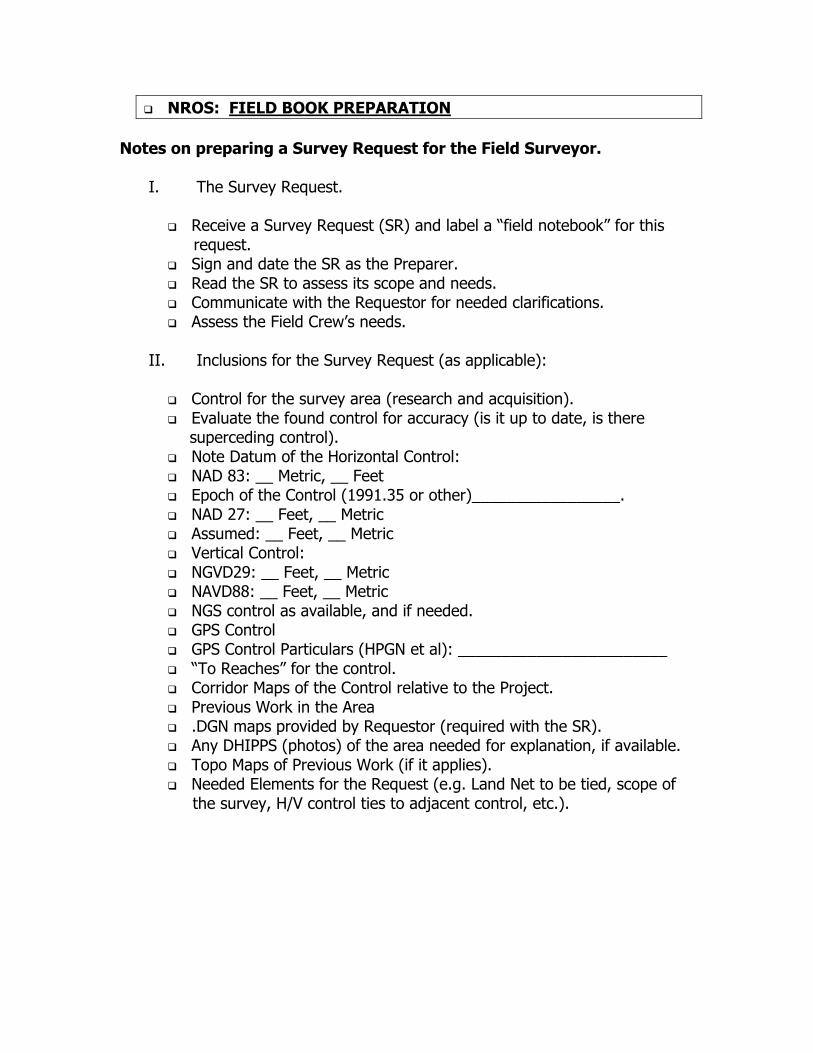
NROS: FIELD BOOK PREPARATION Notes on preparing a Survey Request for the Field Surveyor.
I. The Survey Request.
Receive a Survey Request (SR) and label a “field notebook” for this request.
Sign and date the SR as the Preparer. Read the SR to assess its scope and needs. Communicate with the Requestor for needed clarifications. Assess the Field Crew’s needs.
II. Inclusions for the Survey Request (as applicable):
Control for the survey area (research and acquisition). Evaluate the found control for accuracy (is it up to date, is there
superceding control). Note Datum of the Horizontal Control: NAD 83: __ Metric, __ Feet Epoch of the Control (1991.35 or other)_________________. NAD 27: __ Feet, __ Metric Assumed: __ Feet, __ Metric Vertical Control: NGVD29: __ Feet, __ Metric NAVD88: __ Feet, __ Metric NGS control as available, and if needed. GPS Control GPS Control Particulars (HPGN et al): ________________________ “To Reaches” for the control. Corridor Maps of the Control relative to the Project. Previous Work in the Area .DGN maps provided by Requestor (required with the SR). Any DHIPPS (photos) of the area needed for explanation, if available. Topo Maps of Previous Work (if it applies). Needed Elements for the Request (e.g. Land Net to be tied, scope of
the survey, H/V control ties to adjacent control, etc.).

III. Electronic Files to be supplied (on floppy and/or CD):
Control Files: .CTP CGF (combined grid factor), if needed (needed with HP200), available
through Corpscon. .CTL .DC .ALN or .ALI if alignments are needed or helpful. Caice.zip (if needed or explanatory, usually optional as these large files
are unwieldy on laptops). .DGN maps if useful or provided by Requestor (usually provided as
hard copies).
IV. Assemble the Fieldbook:
SR Maps Control “To reaches for control” Control files on disk or CD Notes and communications “Sign” and date the SR as the Preparer.
V. Deliver the Field Book:
Deliver to Office Senior Office Senior routes to Field Senior Field Senior routes to appropriate Field Crew Party Chief.
VI. Archive/store the Data you send to the field:
“Project” drive under SR, within “Final Content”, or as appropriate.
Optional: On CD under the SR/Project. BTDARE, NROS, SEPTEMBER 2005

Report of Field Survey Checklist
NAME: TITLE:
Report Cover Sheet / Statement of Responsible Charge Scope of Work(SR, EA, COUNTY, ROUTE, PM) Survey Party Members Date(s) of Survey Equipment Used Work Summary - Control
• Control Datum / Pedigree / Problems Encountered w/ Historical Positions • Problem Solving – Assumptions & Methodology • Floated Historical Positions – Reasons / Justification for Floating Points • Suspected Problems / Unresolved Issues
Work Summary – TLI • Logical “Zones” or “Locations” Subdividing Project for Collection • Unusual Situations Encountered / Solutions • 900 Codes Utilized • Statement of Resolution of Crossing Breaklines (CAiCE), with any unusual
solutions or resolutions noted, if they were needed. Work Summary – Boundary / ROW
• Problems / Solutions / Unresolved Issues • Disturbed / Suspect Monuments • Evidence of Encumbered Title (encroachments / occupations, etc.)
Supporting Documents TRIMBLE/TGO/TDS Files, or, CTDC / CTDAP Files
• .DC FILES, Raw .dmp files (electronic copies) • Electronic copies of data collector associated files, primarily .tss and .dc files,
or CTDC/CTDAP equivalents (.apr, .sdb, .sts, .fob, .tss, .ucr and .obs). • Edited TGO files, or .dmp files, if needed (electronic copies w/ cross
references on field notes). STARNET Files
• Files produced from STARNET adjustment of control/traverse points. • .lst (electronic copy and printout)
DIGILEV / STARLEV Files • Files produced from level adjustments (re: .raw, .dat, and .lev, et al) • .dat, .err, .lst, and .prj (electronic copies), if applicable. • .pts (electronic copy and printout)
CAiCE Files • .zip (electronic copy) • Printout of .txt file tracking all edits (optional). An unedited file (.dmp or
TGO version) would suffice. Field Notes (as applicable)
• Traverse, TLI and Trig level note sheets (original copies) • Control Schematic (if not included on traverse notes) • ROW / Property Point Schematic (tied points) • ROW / Property Point Search Schematic (points not found / obliterated) • Corner Records (filed IAW PLS Act) • To Reach Notes (set points and recovered points) • Peg Book Notes (copies of original notes) • Monument Rubbings / Photos
Job Book Remnants Report of Field Survey Checklist
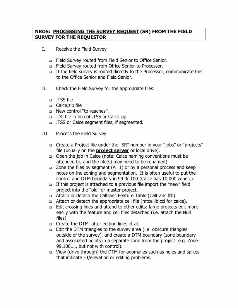
NROS: PROCESSING THE SURVEY REQUEST (SR) FROM THE FIELD SURVEY FOR THE REQUESTOR
I. Receive the Field Survey
Field Survey routed from Field Senior to Office Senior. Field Survey routed from Office Senior to Processor. If the field survey is routed directly to the Processor, communicate this
to the Office Senior and Field Senior.
II. Check the Field Survey for the appropriate files:
.TSS file Caice.zip file New control “to reaches”. .DC file in lieu of .TSS or Caice.zip. .TSS or Caice segment files, if segmented.
III. Process the Field Survey
Create a Project file under the “SR” number in your “jobs” or “projects” file (usually on the project server or local drive). Open the job in Caice (note: Caice naming conventions must be
attended to, and the file(s) may need to be renamed). Zone the files by segment (A=1) or by a personal process and keep
notes on the zoning and segmentation. It is often useful to put the control and DTM boundary in 99 0r 100 (Caice has 10,000 zones.). If this project is attached to a previous file import the “new” field
project into the “old” or master project. Attach or detach the Caltrans Feature Table (Caltrans.ftb). Attach or detach the appropriate cell file (mtcellib.ccl for caice). Edit crossing lines and attend to other edits: large projects edit more
easily with the feature and cell files detached (i.e. attach the Null files). Create the DTM, after editing lines et al. Edit the DTM triangles to the survey area (i.e. obscure triangles
outside of the survey), and create a DTM boundary (zone boundary and associated points in a separate zone from the project: e.g. Zone 99,100,…, but not with control). View (drive through) the DTM for anomalies such as holes and spikes
that indicate HI/elevation or editing problems.
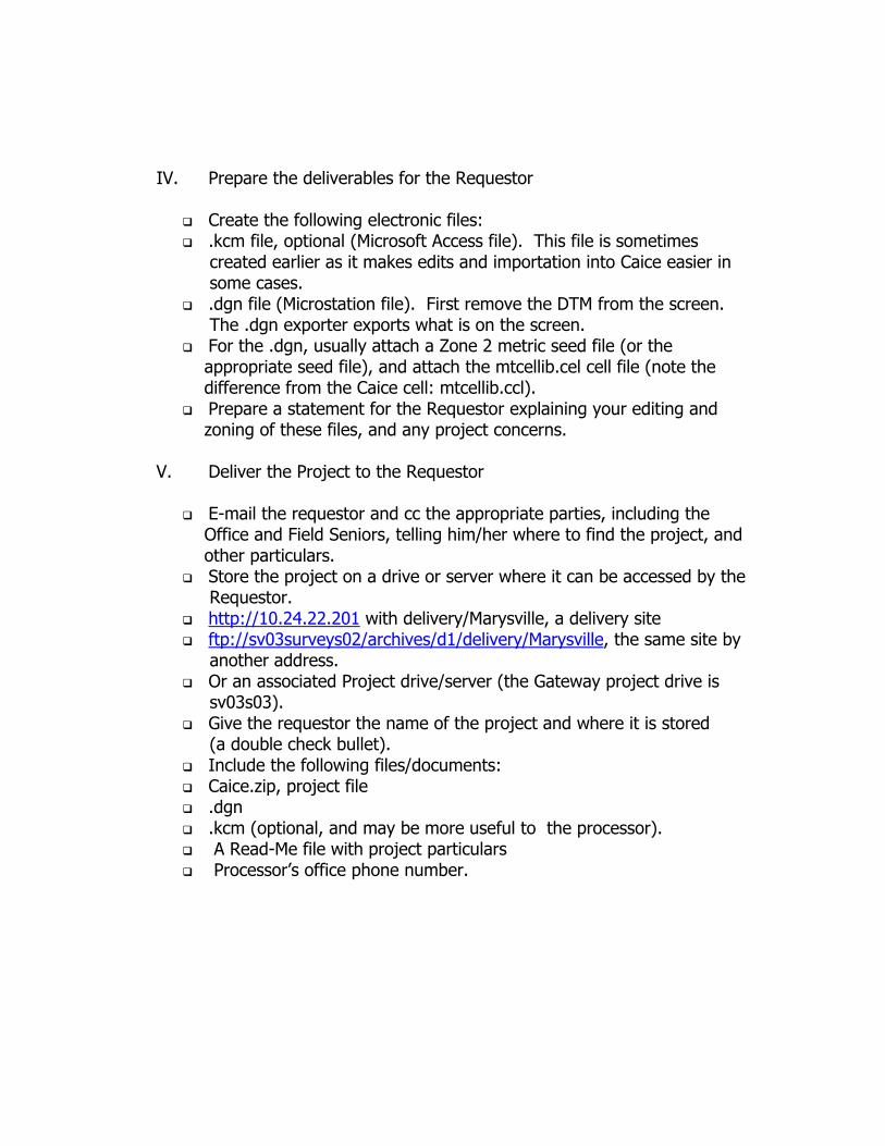
IV. Prepare the deliverables for the Requestor
Create the following electronic files: .kcm file, optional (Microsoft Access file). This file is sometimes
created earlier as it makes edits and importation into Caice easier in some cases. .dgn file (Microstation file). First remove the DTM from the screen.
The .dgn exporter exports what is on the screen. For the .dgn, usually attach a Zone 2 metric seed file (or the
appropriate seed file), and attach the mtcellib.cel cell file (note the difference from the Caice cell: mtcellib.ccl). Prepare a statement for the Requestor explaining your editing and
zoning of these files, and any project concerns.
V. Deliver the Project to the Requestor
E-mail the requestor and cc the appropriate parties, including the Office and Field Seniors, telling him/her where to find the project, and other particulars. Store the project on a drive or server where it can be accessed by the
Requestor. http://10.24.22.201 with delivery/Marysville, a delivery site ftp://sv03surveys02/archives/d1/delivery/Marysville, the same site by
another address. Or an associated Project drive/server (the Gateway project drive is
sv03s03). Give the requestor the name of the project and where it is stored
(a double check bullet). Include the following files/documents: Caice.zip, project file .dgn .kcm (optional, and may be more useful to the processor). A Read-Me file with project particulars Processor’s office phone number.

VI. Archive the Project.
Archive the project on the project drive (e.g.: on the project server: sv03/s01://suv1/03/EAfile#/SR# for District 3. As filing conventions vary slightly within the district and among the districts, the address is slightly variable (the EA may be “older” and have an “s” before the EA number). Archive the various files within the appropriate folder. Book: store a .pdf file of the appropriate field survey notes. Caice: store the processed Caice.zip file (usually SR.zip as 04108.zip). Control: control file for a .ctp, .ctl, or .dc file. MS: store the .dgn or microstation file here. .kcm: store the .kcm with the Caice file. Photo: store any photogrammetry files here (usually not the purview of
the processor, but a good place to possibly find a photogrammetry file related to the project). Optional: Archive on a CD with all the above burned on it. Notify the Office Senior, or appropriate responsible party, that you
have archived the project. BTDARE, SEPTEMBER 13, 2005
Caltrans Quality Management Program PS&E Workgroup
15 – 16 October, 2002 Expectations and Performance Measures of PS&E Customers
(Draft Updated 15 –16 Oct)
Construction / Surveys Expectations Biddable and Buildable Accuracy and consistency between plans, specifications and estimates
Complete and accurate plans (including existing field verified conditions and as-builts information) Clear set of plans Accurate quantities (with checked back up; drainage, electrical etc.) Enough construction detail (especially if non – standard) Accurate estimate (enough money to build job) Project draws accurate bids that are near the engineer’s estimate and at completion of construction, has only nominal contract change orders or claims, and has been built as designed All items have a measurement and payment clause No significant change in quantities due to design error or omissions Appropriate number of working days
Construction work plans (CPM) clearly identifies permit windows including construction windows (environmental, weather, utility, traffic handling, etc.) and sufficient work days
Storm water Pollution Prevention Plan (SWPPP) provided Survey information is correct and complete Survey engineer’s file agree with plan sheets Staging plans and lane closure charts do not conflict
Contract documents clearly identify constraints (construction windows, environmental, cooperative agreements, permits, materials, utilities, right of way, etc.)
Permits, pre-construction permits obtained, construction phase permits identified and related information identified (especially environmental) All right of way elements have been identified Right type Complete and final right of way certification Enough room to do project
1

Caltrans Quality Management Program PS&E Workgroup
15 – 16 October, 2002 Expectations and Performance Measures of PS&E Customers
(Draft Updated 15 –16 Oct)
Utilities relocated prior to construction and identified clearly Property owners have access during construction Special features (driveways, fences, etc)
Safety Safe work environment
Construction staging is realistic, minimizes delays and enhances workers safety Compatible with adjacent projects and/or existing conditions*
Communication Continuous communication through PS&E * (include a field review with construction) (Measures TBD)
Design support through completion of construction All products delivered to RE at or before pre-construction meeting Timely Construction support from all areas Standardized meeting schedule and point of contact for design team during construction Commitments are accurately and fully communicated in a timely fashion RE file, permits, agreements, and mitigation list points of contact (from all functions) RE file is complete RE gets timely (24 hours) and valuable support during construction from design team
2

Caltrans Quality Management Program PS&E Workgroup
15 – 16 October, 2002 Expectations and Performance Measures of PS&E Customers
(Draft Updated 15 –16 Oct) Policy and Procedures All design exceptions have been approved before construction Need and Purpose Minimize change in scope (Measures TBD)
Construction / Surveys Performance Measures Number of CCO’s due to design errors or omissions
Number of CCOs for unidentified contract items Number of CCOs caused by missing or conflicting measurement and pay clauses
Number of RFI’s due to design errors or omissions Number of bidder inquiries Number of contract addendum due to design error or omissions Contractors bid within __% of engineers estimate Number of potential claims Collision rates (type of incidents) during construction Number of design exceptions during construction Number of Cost Reduction Incentive Proposal Number of survey RFI’s
Operations Expectations Need and Purpose Improve traffic operations** Scope issue Improve level of service** Scope issue Safety Meet drivers expectations for traffic delays and safety during construction and provide appropriate detours to minimize travel time
Staging to minimize disruption and delays to drivers Staging to minimize safety issues Adequate access controls to minimize risk of collisions and traffic delays
3

Caltrans Quality Management Program PS&E Workgroup
15 – 16 October, 2002 Expectations and Performance Measures of PS&E Customers
(Draft Updated 15 –16 Oct)
Incident response is rapid, interval time to clean up is minimized As appropriate maximize use of K Rail during construction Minimize construction duration Traffic management plan (maintain access) is fully implemented COZEEP is fully implemented and in accordance with guidelines
Standards and Manuals Design documents in accordance with Caltrans standards, policies and procedures
Traffic features installed according to specification and inspected for compliance Implement contract streamlining measures with objective standards to reduce construction duration Adequate signage and striping to meet drivers expectations and in accordance with standards Meet operations standards
Efficient Project features compatible with total system operations (ramp metering enforcement, signal phasing, etc)
Compatible with adjacent facilities Operations Performance Measures
Measured traffic delays during construction do not exceed specifications Number of public complaints due to unclear design features during construction Number of public complaints due to unclear design features after construction Traffic operations and level of service have been improved after construction Traffic operations and level of service have not been exceeded prior to design life Collision rates (type of incidents) reduced after completion of construction
Maintenance Expectations Safety Safe to operate and maintain
Safe to operate Safe to maintain (enough work space, group roadside fixtures away from traffic or in shielded locations, minimize handwork)
4

Caltrans Quality Management Program PS&E Workgroup
15 – 16 October, 2002 Expectations and Performance Measures of PS&E Customers
(Draft Updated 15 –16 Oct)
Designed to allow easy and safe access for routine maintenance considering equipment constraints. Easy and safe access for routine maintenance
Design for constraints of maintenance equipment to be used on the facility
5

Caltrans Quality Management Program PS&E Workgroup
15 – 16 October, 2002 Expectations and Performance Measures of PS&E Customers
(Draft Updated 15 –16 Oct) Communication Continuous communication through PS&E:
Field review with maintenance
Maintenance needs incorporated into PS&E
Long term commitments communicated to maintenance Maintainable
Designed to provide long life features that are easy and inexpensive to maintain.
Designed to use readily available stock and minimize specialty items. Post PS&E
Timely delivery of as – builts
Electronic version of physical inventory of maintainable items delivered at project completion Maintenance Performance Measures
Safety Minimize the number of maintainable items Routine maintenance items are safely accessible
Communication Commitments are accurately and fully communicated in a timely fashion Routine maintenance has been incorporated into construction reducing the need for immediate maintenance in the construction zone Maintainable
6

Caltrans Quality Management Program PS&E Workgroup
15 – 16 October, 2002 Expectations and Performance Measures of PS&E Customers
(Draft Updated 15 –16 Oct)
Minimize Life cycle cost & Maximize Life of facility as compared with similar facilities. No net increase in maintenance inventory or operations New design features do not require maintenance for 5 years (slopes, culverts, vegetation etc.) Pre-PS&E Flexibility in Funding Post-PS&E Maintainability review checklist is complete
Environmental Expectations Low Impact Project impacts are minimized and limited to the foot print for which environmental compliance has been effected.
Mitigation measures incorporated in PS&E Avoid/minimize construction impacts Construction impacts are limited to the foot print for which environmental compliance has been effected Safe for the environment
Complete & Accurate Mitigation measures and ESA are documented and incorporated into the PS&E.
Mitigation measures incorporated in PS&E Show ESA’s on plan
Biddable & Buildable Environmental permits obtained or identified, and related information incorporated into the PS&E Statutory requirements incorporated into the PS&E
Mitigation measures incorporated in PS&E Work plan incorporates mitigation procedures (construction schedule window) Meets statutory requirements Complete permit request package Permits obtained as appropriate in a timely manner
7

Caltrans Quality Management Program PS&E Workgroup
15 – 16 October, 2002 Expectations and Performance Measures of PS&E Customers
(Draft Updated 15 –16 Oct)
Has permits, environmental permits obtained, environmental phase permits identified and related information identified No enforcement action
Communication Environmental staff included in PS&E development.
Communication during process* Invitation to pre-construction meeting
Global Adequate time and resources to do environmental assessment
Post-PS&E Include environmental on change order construction
8
Caltrans Quality Management Program PS&E Workgroup
15 – 16 October, 2002 Expectations and Performance Measures of PS&E Customers
(Draft Updated 15 –16 Oct)
Environmental Performance Measures Low Impact
Mitigation measures incorporated in PS&E Community consensus is maintained through construction
Biddable & Buildable No increase in construction days or cost (CCOs and claims) due to environmental errors or omissions
No redesign (CCO) due to unidentified permits or impacts beyond previously defined footprint
No re-evaluation of environmental document or additional permits required to build the project as planned No Enforcement Actions
All Requirements and commitments to regulatory agencies, permit requirements and mitigation measures incorporated in PS&E Number of (preferably none) unanticipated permits required during construction Number of (preferably none) environmental reevaluation based on change of footprint during construction or design Number of (preferably none) increase in construction days and cost (CCOs and claims) due to environmental errors or omissions No enforcement actions
Safety Expectations Policies and Procedures Meets design standards, GAD, and design exception fact sheets as appropriate (TBD)
Recoverable slopes (1:4 or flatter) A forgiving roadside - fixed objects in the clear zone removed, relocated, made breakaway, or shielded Design elements shall meet or exceed standards wherever practicable All drainage take into account all reasonably predictable weather condition Traffic management plan or traffic handling plans for all construction projects and account for disabled / emergency vehicles during construction
9

Caltrans Quality Management Program PS&E Workgroup
15 – 16 October, 2002 Expectations and Performance Measures of PS&E Customers
(Draft Updated 15 –16 Oct) Safety Safe for: construction, maintenance, traveling public, emergency vehicles, environment, pedestrians, and bicyclists
Safety that balances maintenance with traveling public Meets drivers expectations during and after construction Provide for disabled vehicles Coordination with local law enforcement agencies
Safety Measures Collision rate related to construction activities Number of public complaints due to unclear design features during construction Number of public complaints due to unclear design features after construction Collision rates (type of incidents) reduced after completion of construction Need for a safety project five years after completion of construction Number of changes during construction (eliminate)
Design Expectations Standards & Manuals Appropriate design speed and standards for driver expectations and adjacent roadway sections
Meets Caltran’s design standards Appropriate design speed for driver expectation and adjacent roadway sections
Efficient Balance customer expectations with cost effective design to achieve the best possible result Makes users benefits available as early as possible
Cost effective design Balance customer expectations as best possible Makes users benefits available as early as possible
Low Impact Balance socio-economic and environmental with project needs.
Consider economic, social, and environmental balance
10

Caltrans Quality Management Program PS&E Workgroup
15 – 16 October, 2002 Expectations and Performance Measures of PS&E Customers
(Draft Updated 15 –16 Oct) Communication Coordinate timely input between technical functions Communicate and secure management concurrence on critical decisions and risk management
Timely and appropriate technical input from other functions Management concurrence on risk design
Global Technical functions provide deliverables on the agreed upon schedule that fits into the overall design for PS&E submittal Each design shall be independently checked by a qualified engineer Each plan sheet shall be signed by a professional engineer who is in responsible charge of the work.
Meets reasonable schedule Separate or independent check of PS&E done
Pre- PS&E Fixed scope/scheduled and cost early in the project
Design Performance Measures Standards & Manuals Balance the need for the project with design standards using engineering judgement Engineering Decisions Documented (Permanent History File)
• Risk Design • Independent Checks (Backup) • Environmental Commitments • Technical reports completed
In accordance with all Caltrans standards and policies Independent design check has been completed and documented Engineering Decisions Documented
Global Maintenance, traffic and hydraulics are satisfied with the project
Quantities calculations and backups are included in a complete RE file
11

Caltrans Quality Management Program PS&E Workgroup
15 – 16 October, 2002 Expectations and Performance Measures of PS&E Customers
(Draft Updated 15 –16 Oct) Efficient Design effort is proportionate to product completeness Construction costs is balanced with project need Minimal redesign effort
Earned value Value analysis has been performed Minimal redesign effort
Communication No unresolved conflicts between functional components of overall design Overall design meets management expectations Pre-PS&E
Project Change Request (scope, cost, schedule) is not needed Right of Way Expectations
Biddable and Buildable Right of way requirements include all state facilities and cover all constructed work
All easements are identified Right of way obligations shown on plans and specifications
Policies and Procedures Railroad agreements are complete and comprehensive (Measures 1,2,3) State’s liability on utilities is minimized
Utility agreements are complete and comprehensive All utilities relocation are complete prior to construction as applicable All utilities are in conformance with state policies and procedures
12

Caltrans Quality Management Program PS&E Workgroup
15 – 16 October, 2002 Expectations and Performance Measures of PS&E Customers
(Draft Updated 15 –16 Oct) Timely and complete right of way transmittals
Right of Way Performance Measures Right of way delay cost Right of way certification delays Number of revisions by design after certificate of sufficiency Number of revisions by design after right of way certification No unidentified utilities encountered on project
*Global Expectations Need and purpose should be stated in clear, measurable, and should relate to better service, greater safety, or preserving the structural integrity of a facility Meets standards and manuals Communication plans with appropriate functions Safety Consistent with regional plans, customer expectations and other projects in area Periodic PDT meetings take place throughout PS&E and include all stakeholders
Global Performance Measures Keep orderly and complete project files Check design against need and purpose at appropriate milestones Accurate meeting minutes and decisions documented
13
Appendixes Project Development Forms and Letters plus Policy and Procedures Documents
SURVEY FILE CHECKLIST
Co. Rte. KP (PM): EA: Project Limits:
Project Manager: Phone: Design Senior: Phone: Project Engineer: Phone: Design Team Contacts: Phone: Phone: Phone:
1) Horizontal Datum and Existing Alignment History
Metric coordinates, bearings and grid distances are based on: (see options below)
California Coordinate System - Zone (1 – 6): CCS83 (1991.35) CCS83 (pre-HPGN) CCS27 (USC&GS 1965) Other:
Method alignments were generated:
Existing CCS83 alignments from as-builts “Best-fit” to CCS83 photogrammetric topographic data “Best-fit” to CCS83 survey topographic data Generated by Surveys Office Other:
If metric stationing is based on English as-builts identify a major tie point: Metric station is equivalent to English station .
Identify or deliver all as-built documentation referenced for existing alignment.
2) Vertical Datum
Elevations are based on (see options below) NGVD29 NAVD88 Other:
3) Design Documentation and Electronic Format Design Files
The electronic formatted deliverables requested in the following table are recommended files known to be compatible with Caltrans current Design software, Microstation and CAiCE.
Discuss alternate electronic formats with the District Surveys Office during the Constructability Review Process.
Appendix GG 12/21/2005 Project Development Procedures Manual Page 1 of 8

Appendix GG – Project Data Checklists Survey File Checklist
SURVEY FILE CHECKLIST
Required Deliverables – Hardcopy (Electronic Files as noted)
Date Required
Date Provided Remarks
1. Preliminary Plans (See Section 5 1a & 2a)
Prior to PS&E
2. Final Contract Plans (See Section 5 2b) (Do we want/need electronic?) Reduced (11” x 17”) Full size (on request)
RTL
3. Base Map – Electronic Format Only (See Section 5 2a) Roadway, structural, and drainage layouts, and contours
RTL
4. Roadway Alignments (See Section 5 1a or 1b) Main lines, Ramps, & Branch Connections Frontage Roads Detours Other
Preliminary 30%
Updates
60% & 95%
Final PS&E
5. Structural Layout Lines (See Section 5 1a or 1b) Retaining and sound wall LOL’s Bridge abutment and wing wall LOL’s Curb returns and pullouts not parallel with roadway alignments Pipes and culverts over 60 m long or those containing curves and angle points
Preliminary 30%
Updates
60% & 95%
Final PS&E
6. Profiles for items requiring vertical control for construction (See Section 5 1a or 1b) Roadways Median Barriers Retaining Walls Curb Return gutters Ditch Other
Preliminary 30%
Updates
60% & 95%
Final PS&E
7. Rights of Way (See Section 5 1a or 1b)
Final traverse and R/W Maps approved by R/W Engineering.
PS&E
Appendix GG 12/21/2005 Project Development Procedures Manual Page 2 of 8

Appendix GG – Project Data Checklists Survey File Checklist
SURVEY FILE CHECKLIST
Required Deliverables – Hardcopy (Electronic Files as noted)
Date Required
Date Provided Remarks
8. Roadway Cross-Sections (See Section 5 1a & 1c) Hardcopy on request Minimum of 20 m station intervals Minimum of 10 m station intervals On curves with a radius equal to
or less than 300 m When the profile grade is less
than 0.3%, the minimum profile grade allowed without an exception
Include a cross-section for all begin/end of curves, roadway tapers, roadway pullouts, angle point locations, begin/end high side super, etc. Include all planes necessary for staking finish roadbeds, including slopes, benches, and ditches Slope rounding when applicable Include all cross slopes, including areas of “Pavement Plane Projection” or “Match Existing Cross Slope” Include offsets to R/W if the slope catch point is within 3 m of the R/W Tapered sections at on/off ramp connections shall be included in the main line listings up to and including the nose (or end) of the gore paving area. The remaining portion of each ramp is to be listed separately. When two alignments are converging or diverging, provide a match line between both slope stake listing segments until the alignments become completely separated.
Preliminary
60%
Updates 95%
Final PS&E
9. Roadway Slope Stake Listings (1 or 2 per page) (See Section 5 1d) Millimeter accuracy for both horizontal and vertical labels Finish Grade only Minimum of 20 m station intervals Minimum of 10 m station intervals On curves with a radius equal to
or less than 300 m
Preliminary
60%
Updates 95%
Final
PS&E
Appendix GG 12/21/2005 Project Development Procedures Manual Page 3 of 8

Appendix GG – Project Data Checklists Survey File Checklist
SURVEY FILE CHECKLIST
Required Deliverables – Hardcopy (Electronic Files as noted)
Date Required
Date Provided Remarks
When the profile grade is less than 0.3%, the minimum profile grade allowed without an exception
Include a station listing for all begin/end of curves, roadway tapers, roadway pullouts, angle point locations, begin/end high side super, etc. Include all planes necessary for staking finish roadbeds, including slopes, benches, and ditches Slope rounding when applicable Include all cross slopes, including areas of “Pavement Plane Projection” or “Match Existing Cross Slope” Include offsets to R/W if the slope catch point is within 3 m of the R/W Tapered sections at on/off ramp connections shall be included in the main line listings up to and including the nose (or end) of the gore paving area. The remaining portion of each ramp is to be listed separately. When two alignments are converging or diverging, provide a match line between both slope stake listing segments until the alignments become completely separated.
10. Documentation identifying the horizontal alignments, profiles, and cross section files delivered in electronic format. (See Section 7 - Electronic File Reference Listing)
PS&E
4) Required Items on Contract Plans
THESE ITEMS MAY BE MOVED TO THE PS&E CHECKLIST SINCE THEY ARE REQUIRED WELL BEFORE PS&E
The following items are important in the construction phase of a project and should be shown on the Contract Plans.
Appendix GG 12/21/2005 Project Development Procedures Manual Page 4 of 8
CONTRACT PLAN REQUIREMENTS 1. Roadway alignment data for all stationed lines (main lines, ramps, frontage roads, detours, branch
connections, etc.) to include: Stationing at all angle points and at the beginning and endings of curves Station Equations
Appendix GG – Project Data Checklists Survey File Checklist
SURVEY FILE CHECKLIST
CONTRACT PLAN REQUIREMENTS Line & Curve data
2. Drainage Facilities – including Ditches & Channels a. Alignment References (Station/offset for horizontal and vertical angle points, end points, and curve data of the drainage facility.) Cross-sections Structure Locations
(Provide station/offset to the centerline point at the flow line of all structures.) Skews (if not 90°) Crosscheck Drainage Plan, Profile, Details, and Quantity Sheets for consistency.
3. Bridge Structures Abutment and wing wall lay-out lines and references to footings Abutment fills Needs more explanation Pier/Bent alignments
4. Structural Lay-out Lines (Provide station/offsets for angle points, begin/end curves, and end points, curve data, bearings, and distances)
Retaining Walls and Noise Barriers (Berms) Benches Curb Returns Other
5. Minor Structures Locations Signs Signals Lighting Foundations Other
6. Utilities Any specifics?
7. Taper, Transition Curves, and Flare Locations (Sufficient data to precisely define and differentiate tapers and flares: begin & end roadway tapers and super transitions, radius point, offset, and parabolic curve base line distances, offsets, and direction.)
Guard Rails Pavement Edges Pull outs Other
8. Profiles Roadways Curb & Gutter Median barriers Ditches or Channels Other
Appendix GG 12/21/2005 Project Development Procedures Manual Page 5 of 8

Appendix GG – Project Data Checklists Survey File Checklist
SURVEY FILE CHECKLIST
CONTRACT PLAN REQUIREMENTS 9. Super Elevations (Sufficient data to precisely define begin & end of transitions and grade.)
10. Construction Details - Staking Plans shown in detail when slope stake listings do not adequately depict the area to be constructed.
5) Recommended Digital File Formats
1: Recommended CAiCE files:
All of the Geometry Chains, Profiles, and Cross-sections that are required in the construction of the project should be delivered to the District Surveys Office with a completed Electronic File Reference Listing, found in Section 7 below. a. CAiCE Project Archive (*.ARC or *.ZIP)
A CAiCE Project Archive should include the Existing Survey data and only those objects required in the construction of the project. Extraneous data should be removed from the project before archiving.
Included objects: Geometry Chains and associated Points and Curves Profiles Cross-sections Design Digital Terrain Models.
Please specify if WinZip is used to package the project files instead of the CAiCE Archive Utility.
b. CAiCE Database Explorer File (*.KCM) A CAiCE Database Explorer File should include only those objects required in the construction of the project. Extraneous data should not be included in the delivered KCM file.
Included objects: Geometry Chains and associated Points and Curves Profiles
c. CAiCE End Area File (*.EAR) Only the final Cross-section files required in the construction of the project should be delivered.
d. Microsoft Word document (*.DOC) and/or Slope Stake Note Generator 3.1 Report File (*.SSR)
Slope Stake Listings must be generated from the final Cross-section files required in the construction of the project.
2: Recommended Microstation Design files (*.DGN):
a. Basemap and associated design files with the coordinate design plane still intact, prior to submittal for PS&E. At a minimum the file(s) should contain roadway, structural and drainage layouts, and any contours created for the construction of the project.
b. Contract Plans as submitted to PS&E (Coordinates may or may not contain the values based on the California Coordinate System). Do we really need this??????????????????
6) Typical Grade Break Headers
We still need to work with CADD about standardizing these
Appendix GG 12/21/2005 Project Development Procedures Manual Page 6 of 8

Appendix GG – Project Data Checklists Survey File Checklist
SURVEY FILE CHECKLIST
BSW - Back of Sidewalk CONT or CON - Contour-grading point CP - Catch Point (Cut or Fill) DIKT – Top of Dike EB – Edge of Barrier EOD – Edge of Deck DEP - Designed Edge of Pavement DES - Designed Edge of Shoulder DETW – Designed Edge of Travel Way DFL - may designate any Designed flow line of a ditch, curb, or dike DTOP – Designed Top of Ditch GTR - Gutter HP or HNG - Hinge Point LIP - Lip of curb & gutter LOL - Layout Line for walls (Use Mainline, Gore area or Ramp alignment name for layout line) PG - Profile Grade R/W – Right of Way S/C– Sawcut TC - Top of Curb TOE - Toe of Sound Berm/Ditch TOP - Top of Sound Berm/Ditch
(If there is more than one plane of the same callout then number the planes if possible. For example, DETW1, DETW2, or HP1, HP2 etc.)
Appendix GG 12/21/2005 Project Development Procedures Manual Page 7 of 8

Appendixes Project Development Forms and Letters plus Policy and Procedures Documents
SURVEY FILE CHECKLIST
7) Electronic File Reference Listing Co. Rte. KP (PM): EA:
Full un-restricted path to the electronic format project data files:
Alignment/Layout Line Profile Cross Section & Slope Stake Notes
Alignment Name CAiCE Name Profile Name CAiCE Name
CAiCE Deliverable KCM file name EAR file name DOC &/or SSR file
name
Additional Comments:
Additional Comments:
Additional Comments:
Additional Comments:
Additional Comments:
Additional Comments:
Appendix GG 12/21/2005 Project Development Procedures Manual Page 8 of 8
Top Related