


Languages
Pages
Legal


TECHNICAL & SERVICE MANUAL
SPLIT-TYPE, HEAT PUMP AIR CONDITIONERS
No.OC322
R410AOutdoor unit[model names] [Service Ref.]SUZ-KA25VA SUZ-KA25VA.THSUZ-KA35VA SUZ-KA35VA.THSUZ-KA25VAH SUZ-KA25VAH.THSUZ-KA35VAH SUZ-KA35VAH.THSUZ-KA50VA SUZ-KA50VA.TH
SUZ-KA50VA 1.THSUZ-KA60VA SUZ-KA60VA.TH
SUZ-KA60VA 1.THSUZ-KA71VA SUZ-KA71VA.TH
SUZ-KA71VA 1.TH
CONTENTS
1. COMBINATION OF INDOOR AND OUTDOOR UNITS ······22. TECHNICAL CHANGES ···································23. PART NAMES AND FUNCTIONS······················64. SPECIFICATION·················································75. NOISE CRITERIA CURVES ·····························116. OUTLINES AND DIMENSIONS ·······················127. WIRING DIAGRAM ··········································148. REFRIGERANT SYSTEM DIAGRAM··············189. PERFORMANCE CURVES······························22
10. ACTUATOR CONTROL····································5011. SERVICE FUNCTIONS·····································5112. TROUBLESHOOTING······································5113. DISASSEMBLY INSTRUCTIONS·····················8414. PARTS LIST······················································9115. RoHS PARTS LIST···········································97
Indication ofmodel name
NOTE:This service manual describes technical data of the outdoor units.•As for indoor units SLZ-KA25/35/50VA(L).TH and SEZ-KA35/50/60/71VA.TH, refer to the service manualOC320 and OC321.
HFCutilized
R410A
SUZ-KA25VA(H).TH SUZ-KA35VA(H).TH
March 2007
REVISED EDITION-C
Revision:• SUZ-KA50/60/71VA1.TH
are added in REVISEDEDITION-C.
• Some descriptions havebeen modified.
• Please void OC322REVISED EDITION-B.
Note:• RoHS compliant products
have <G> mark on thespec name plate.
• For servicing of RoHScompliant products, referto the RoHS Parts List.
OC322C--1qxp 07.3.12 3:43 PM Page 1

2
1 COMBINATION OF INDOOR AND OUTDOOR UNITS
Heat pump typeOutdoor unit
SUZ-
SLZ-KA25VA(L).TH
SLZ-KA35VA(L).TH
SLZ-KA50VA(L).TH
SEZ-KC25VA.W
SEZ-KA35VA.TH
SEZ-KA50VA.TH
SEZ-KA60VA.TH
SEZ-KA71VA.TH
MFZ-KA25VA-E1
MFZ-KA35VA-E1
MFZ-KA50VA-E1
—
—
—
—
—
—
—
—
—
—
—
—
—
—
—
—
—
—
—
—
—
—
—
—
—
—
—
—
—
—
—
—
—
—
—
—
—
—
—
—
—
—
—
—
OC320
—
OC321
OB409
Indoor unit
ServiceManual No.
Service Ref.
H
eat
pu
mp
wit
ho
ut
elec
tric
hea
ter
KA35VA(H).THKA25VA(H).TH KA60VA(1).TH KA71VA(1).THKA50VA(1).TH
2 TECHNICAL CHANGES
(NOTE)Only the combination data of SLZ type and SEZ type have been described in this manual.Please refer to the service manual of indoor unit or the technical data book for other combination.
Revision B:· Compressor has been changed. (SUZ-KA50/60VA)
Previous
New
Model
SNB130FLDH
SNB130FLDH1
PARTS LIST number
E02 851 900
E02 939 900
RoHS PARTS LIST number
E12 851 900
E12 939 900
SUZ-KA50VA.TH SUZ-KA50VA 1.THSUZ-KA60VA.TH SUZ-KA60VA 1.THSUZ-KA71VA.TH SUZ-KA71VA 1.TH1.OUTDDOOR ELECTRONIC CONTROL P.C. BOARD has been changed.2.Max. height difference 15m 30m (Except when combined with MFZ).3.Garanteed operating range
Lower limit (Cooling/Outdoor) -10:DB-15:DB (Except when combined with MFZ)
SUZ-KA25VA.THSUZ-KA35VA.THLower limit (Heating/Outdoor) -10:DB-15:DB.
SUZ-KA35VAH.THDefrost finish temperature has been changed (Refer to 11).
OC322C--1qxp 07.3.12 3:43 PM Page 2

Ref
riger
ant
oil
Ref
riger
ant
New refrigerantR410A
HFC-32: HFC-125 (50%:50%)Pseudo-azeotropic refrigerant
Not includedA1/A172.6-51.41.557
64Non combustible
01730
From liquid phase in cylinderPossible
Incompatible oilNonNon
Previous refrigerantR22
R22 (100%)Single refrigerant
IncludedA1
86.5-40.80.9444.4
Non combustible0.0551700
Gas phasePossible
Compatible oilLight yellow
Non
RefrigerantComposition (Ratio)Refrigerant handlingChlorineSafety group (ASHRAE)Molecular weightBoiling point (:)Steam pressure [25:](Mpa)Saturated steam density [25:](Kg/K)CombustibilityODP w1GWP w2Refrigerant charge methodAdditional charge on leakageKindColorSmell
w1 :Ozone Depletion Potential : based on CFC-11w2 :Global Warming Potential : based on CO2
3
SUZ-A09VR.TH SUZ-KA25VA.THSUZ-A12VR.TH SUZ-KA35VA.TH1.Indication of capacity has been changed.(BTU basekW base)2.Control method between indoor and outdoor unit has been changed.3.Power supply method has been changed (change to supply from outdoor unit).4. Terminal block for power supply has been added.5.Power P.C.board has been changed.6.Inverter P.C. board has been changed.7.Refrigerant circuit has been changed.
• Compressor has been changed.(KNB073FBVHKNB073FDVH:SUZ-KA25VA) (KNB092FAAHKNB092FCAH:SUZ-KA35VA)• Specification and position of muffler have been changed. • Path of outdoor heat exchanger has been changed.• 4-way valve and R.V. coil have been changed.• Stop valve has been changed.
8.Fan motor has been changed.(ACDC)9.Shape of grille has been changed.
10.Shape of service panel has been changed.11.Shape of propeller has been changed.12.Symbol on terminal block has been changed (to S1/S2/S3).
SUZ-A18VR SUZ-KA50VA.THSUZ-A24VR SUZ-KA60VA.TH
1.Indication of capacity has been changed.(BTU base kW base)2.Power supply method has been changed (change to supply from outdoor unit).3.Outdoor electronic control P.C. board has been changed.4.Noise filter P.C. board has been changed.5.Length of fan motor lead wire has been changed.6.Shape of relay panel has been changed.7.Symbol on terminal block has been changed (to S1/ S2/ S3).8.Control method between indoor and outdoor unit has been changed.
INFORMATION FOR THE AIR CONDITIONER WITH R410A REFRIGERANT• This room air conditioner adopts an HFC refrigerant (R410A) which never destroys the ozone layer.• Pay particular attention to the following points, though the basic installation procedure is same as that for R22 conditioners.1As R410A has working pressure approximate 1.6 times as high as that of R22, some special tools and piping parts/
materials are required. Refer to the table below.2Take sufficient care not to allow water and other contaminations to enter the R410A refrigerant during storage and
installation, since it is more susceptible to contaminations than R22.3For refrigerant piping, use clean, pressure-proof parts/materials specifically designed for R410A. (Refer to 2. Refrigerant
piping.)4Composition change may occur in R410A since it is a mixed refrigerant. When charging, charge liquid refrigerant to prevent
composition change.
OC322C--1qxp 07.3.12 3:43 PM Page 3

-30 -20 -10 0 10 20 30 40 50 60-0.5
0.0
0.5
1.0
1.5
2.0
2.5
3.0
3.5
4.0(MPa [Gauge])
R410A
R22
Conversion chart of refrigerant temperature and pressure
Sat
urat
ed li
quid
pre
ssur
e
(:)
NOTE : The unit of pressure has been changed to MPa on the international system of units(SI unit system).
The conversion factor is: 1(MPa [Gauge]) =10.2(kgf/ ff [Gauge])
R410A tools Can R22 tools be used?
Gas leak detector
R410A has high pressures beyond the measurement range of existing gauges. Port diameters have been changed to prevent any other refrigerant from being charged into the unit.
Hose material and cap size have been changed to improve the pressure resistance.Dedicated for HFC refrigerant.
6.35 mm and 9.52 mm
Description
Clamp bar hole has been enlarged to reinforce the spring strength in the tool.
Provided for flaring work (to be used with R22 flare tool).Provided to prevent the back flow of oil. This adapter enables you to use vacuum pumps.It is difficult to measure R410A with a charging cylinder because the refrigerant bubbles due to high pressure and high-speed vaporization
No
No
No
Yes
Yes
New
New
New
Gauge manifold
Charge hose
Torque wrench
Flare tool
Flare gaugeVacuum pumpadapter
Electronic scale forrefrigerant charging
No : Not substitutable for R410A Yes : Substitutable for R410A
No 12.7 mm and 15.88 mm
1. Tools dedicated for the air conditioner with R410A refrigerantThe following tools are required for R410A refrigerant. Some R22 tools can be substituted for R410A tools.The diameter of the service port on the stop valve in outdoor unit has been changed to prevent any other refrigerant being charged into the unit. Cap size has been changed from 7/16 UNF with 20 threads to 1/2 UNF with 20 threads.
4
NOTE : The unit of pressure has been changed to MPa on the international system of units(SI unit system).The conversion factor is: 1(MPa [Gauge]) =10.2(kgf/ ff [Gauge])
New Specification Current Specification
The incompatible refrigerant oil easily separates from refrigerant and is in the upper layer inside the suction muffler.Raising position of the oil back hole enables to back the refrigerant oil of the upper layer to flow back to the compressor.
Since refrigerant and refrigerant oil are compatible each, refrigerant oil backs to the compressor through the lower position oil back hole.
Compressor
Suction muffler
Oil back hole
Refrigerant oil
Refrigerant
Compressor
Suction muffler
Oil back hole
Refrigerant oil /Refrigerant
Com
pres
sor
OC322C--1qxp 07.3.12 3:43 PM Page 4

Electronic scale for refrigerant charging
Outdoor unit
Refrigerant gas cylinderoperating valve
Refrigerant gas cylinderfor R410A with siphon
Refrigerant (liquid)
Service port
Gauge manifold valve (for R410A)
Union
Liquid pipe
Gas pipe
Stop valve
Indoor unit
Charge hose (for R410A)
R410APipe diameter (mm)
6.359.5212.715.88
17222629
Dimension of flare nut (mm)
R22
17222427
• Use a copper pipe or a copper-alloy seamless pipe with a thickness of 0.8 mm. Never use any pipe with a thickness less than 0.8mm, as the pressure resistance is insufficient.
2Flaring work and flare nutFlaring work for R410A pipe differs from that for R22 pipe.For details of flaring work, refer to Installation manual “FLARING WORK”.
3. Refrigerant oilApply the special refrigerant oil (accessories: packed with indoor unit) to the flare and the union seat surfaces.
4. Air purge• Do not discharge the refrigerant into the atmosphere.
Take care not to discharge refrigerant into the atmosphere during installation, reinstallation, or repairs to the refrigerant circuit.
• Use the vacuum pump for air purging for the purpose of environmental protection.
5. Additional chargeFor additional charging, charge the refrigerant from liquid phase of the gas cylinder. If the refrigerant is charged from the gas phase, composition change may occur in the refrigerant inside the cylinder and theoutdoor unit. In this case, ability of the refrigerating cycle decreases or normal operation can be impossible. However, charging the liquid refrigerant all at once may cause the compressor to be locked. Thus, charge the refrigerant slowly.
2. Refrigerant piping1Specifications
Use the refrigerant pipes that meet the following specifications.
Wall thicknessOutside diameterPipe
mm mm
For liquid
For gas
6.359.529.5212.715.88
0.80.80.80.81.0
Heat resisting foam plastic Specific gravity 0.045 Thickness 8 mm
Insulation material
5
OC322C--1qxp 07.3.12 3:43 PM Page 5

6
3 PART NAMES AND FUNCTIONS
OUTDOOR UNITAir inlet
Air outlet
Drain outlet
Piping
Drain hose
(back and side)
ACCESSORIES
1 Drain socket 1
SUZ-KA25VA.THSUZ-KA35VA.TH
SUZ-KA25VA.TH SUZ-KA35VA.THSUZ-KA25VAH.THSUZ-KA35VAH.TH
OUTDOOR UNITAir inlet
Piping
Air outlet
(back and side)
Drain hose
Drain outlet
ACCESSORIES
1
2
Drain socket
Drain cap [33
1
2
SUZ-KA50VA(1).THSUZ-KA60VA(1).THSUZ-KA71VA(1).TH
SUZ-KA50VA.TH SUZ-KA50VA 1.THSUZ-KA60VA.TH SUZ-KA60VA 1.THSUZ-KA71VA.TH SUZ-KA71VA 1.TH
OC322C--1qxp 07.3.12 3:43 PM Page 6
7
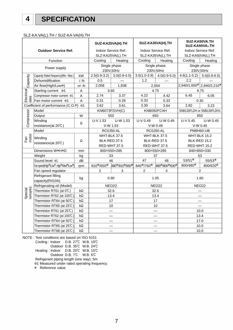
SPECIFICATION4
Function
Power supply
Outdoor Service Ref.
Capacity Rated frequency(Min.~Max.)DehumidificationAir flow(High/Loww)Starting current 1Compressor motor current 1Fan motor current 1
ModelOutputWindingresistance(at 20:)Model
Windingresistance(at 20:)
Dimensions WOHODWeightSound level 1Fan speed(Highw/Loww, Highw/Medw/Loww)Fan speed regulatorRefrigerant fillingcapacity(R410A)Refrigerating oil (Model)Thermistor RT61 (at 0:)Thermistor RT62 (at 100:)Thermistor RT64 (at 50:)Thermistor RT65 (at 25:)Thermistor RT61 (at 25:)Thermistor RT62 (at 100:)Thermistor RT64 (at 50:)Thermistor RT65 (at 25:)Thermistor RT68 (at 25:)
kWr/hK /h
AAA
W
"
"
mmkgdBrpm
kg
k"k"k"k"k"k"k"k"k"
Single phase230V,50Hz
3.65
KNB073FDVH(C)550
U-V 1.53 U-W 1.53 V-W 1.53
RC0J50-ALWHT-BLK 37.5 BLK-RED 37.5RED-WHT 37.5800o550o285
3346
0.90
NEO2232.613.41710—————
Cooling
2.5(0.9-3.2)0.5
2,058
2.740.313.62
810w/650w
2880w/810w/650w
3840w/760w
2880w/800w/630w
3
Heating
3.0(0.9-4.5)—
1,938
3.370.283.61
SUZ-KA25VA(H).TH
Indoor Service Ref. SLZ-KA25VA(L).TH
Indoor Service Ref. SLZ-KA35VA(L).TH
Com
pres
sor
Fan
m
otor
Spe
cial
rem
arks
Coefficient of performance (C.O.P) 1
Cap
acity
Ele
ctric
alda
ta
SUZ-KA35VA(H).TH
Single phase230V,50Hz
2,0044.75
KNB092FCAH650
U-V 0.49 U-W 0.49 V-W 0.49
RC0J50-ALWHT-BLK 37.5BLK-RED 37.5 RED-WHT 37.5800o550o285
37
1.05
NEO2232.613.41710—————
Cooling
3.5(1.0-3.9)1.2
4.220.333.30
47
Heating
4.0(0.9-5.0)—
4.420.333.64
48
Indoor Service Ref. SLZ-KA50VA(L).TH
SUZ-KA50VA.THSUZ-KA50VA1.TH
Single phase230V,50Hz
6.75
0.30
SNB130FLDH or SNB130FLDH1850
U-V 0.45 U-W 0.45 V-W 0.45
PM8H60-UBWHT-BLK 15.2 BLK-RED 15.2RED-WHT 15.2840o850o330
53
2
1.60
NEO22————
10.013.417.010.010.0
Cooling
4.6(1.1-5.2)2.2
2,940/1,650w
6.45
2.82
53/51w
800/480w
Heating
5.0(0.9-6.5)—
2,940/2,210w
6.05
3.23
55/53w
800/620w
NOTE : Test conditions are based on ISO 5151Cooling : Indoor D.B. 27: W.B. 19:
Outdoor D.B. 35: W.B. 24:Heating : Indoor D.B. 20: W.B. 15:
Outdoor D.B. 7: W.B. 6:Refrigerant piping length (one way): 5m1 Measured under rated operating frequency.w Reference value
SLZ-KA·VA(L).TH / SUZ-KA·VA(H).TH
OC322C--1qxp 07.3.12 3:43 PM Page 7

8
Single phase230V,50Hz
3.65
KNB073FDVH(C)550
U-V 1.53 U-W 1.53 V-W 1.53
RC0J50-ALWHT-BLK 37.5BLK-RED 37.5RED-WHT 37.5800o550o285
3346
0.90
NEO2232.613.41710
Cooling
2.5(0.9-3.2)1.0
2,058
2.740.313.42
810w/650w
2
Heating
3.0(0.9-4.5)—
1,938
3.370.283.61
880w/810w/650w
3
Single phase230V,50Hz
2,0044.75
KNB092FCAH650
U-V 0.49 U-W 0.49 V-W 0.49
RC0J50-ALWHT-BLK 37.5BLK-RED 37.5RED-WHT 37.5800o550o285
37
1.05
NEO2232.613.41710
Cooling
3.5(1.0-3.9)1.2
4.220.333.30
47840w/760w
2
Heating
4.0(0.9-5.0)—
4.420.333.64
48880w/800w/630w
3
Outdoor Service Ref.
Function
Power supply
Capacity Rated frequency(Min.-Max.)DehumidificationAir flow 1 Starting current (Total) 1Compressor motor current 1Fan motor current 1
ModelOutputWindingresistance(at 20:)Model
Windingresistance(at 20:)
Dimensions WOHODWeightSound level 1Fan speed(Highw/Loww, High/Med.w/Loww)Fan speed regulatorRefrigerant fillingcapacity(R410A)Refrigeration oil (Model)Thermistor RT61(at 0:)Thermistor RT62(at 100:)Thermistor RT64(at 50:)Thermistor RT65(at 25:)
kWr/hK /h
AAA
1
W
"
"
mmkg
dB(A)rpm
kg
k"k"k"k"
Com
pres
sor
Fan
m
otor
Spe
cial
rem
arks
Coefficient of performance(C.O.P)
Cap
acity
Ele
ctric
alda
ta
SUZ-KA25VA(H).THIndoor Service Ref.
SEZ-KC25VA.W
SUZ-KA35VA(H).THIndoor Service Ref. SEZ-KA35VA.TH
NOTE : Test conditions are based on ISO 5151Cooling : Indoor Dry-bulb temperature 27:Wet-bulb temperature 19:
Outdoor Dry-bulb temperature 35:Wet-bulb temperature(24:)Heating : Indoor Dry-bulb temperature 20:Wet-bulb temperature 15:
Outdoor Dry-bulb temperature 7: Wet-bulb temperature 6:Refrigerant piping length (one way): 5m1 Measured under rated operating frequency w Reference value
SEZ-KC·VA.W, SEZ-KA·VA.TH / SUZ-KA·VA(H).TH
OC322C--1qxp 07.3.12 3:43 PM Page 8

9
Function
Power supply
Outdoor Service Ref.
Capacity Rated frequency(Min.~Max.)DehumidificationAir flow(High/Loww)Starting current 1Compressor motor current 1Fan motor current
ModelOutputWindingresistance(at 20:)Model
Windingresistance(at 20:)
Dimensions WOHODWeightSound level(High/Loww)Fan speed(High/Loww)Fan speed regulatorRefrigerant fillingcapacity(R410A)Refrigerating oil (Model)Thermistor RT61 (at 25:)Thermistor RT62 (at 100:)Thermistor RT64 (at 50:)Thermistor RT65 (at 25:)Thermistor RT68 (at 25:)
kWr/hK /h
AAA
W
"
"
mmkgdBrpm
kg
k"k"k"k"k"
Indoor Service Ref. SEZ-KA50VA.TH
Com
pres
sor
Fan
m
otor
Spe
cial
rem
arks
Coefficient of performance(C.O.P)
Cap
acity
Ele
ctric
alda
ta
SUZ-KA50VA.THSUZ-KA50VA1.TH
Single phase230V,50Hz
6.75
0.30
SNB130FLDH or SNB130FLDH1850
U-V 0.45 U-W 0.45 V-W 0.45
RC0J60-AABLK-WHT 15.2WHT-RED 15.2RED-BLK 15.2 840o850o330
53
2
1.60
NEO2210.013.417.010.010.0
Cooling
5.0(1.1-5.6)1.9
2,940/1,650w
6.45
2.81
53/51w
800/480w
Heating
5.9(1.1-7.2)—
2,940/2,210w
6.05
3.21
55/53w
800/620w
Indoor Service Ref. SEZ-KA60VA.TH
SUZ-KA60VA.THSUZ-KA60VA1.TH
Single phase230V,50Hz
9.75
0.30
SNB130FLDH or SNB130FLDH1850
U-V 0.45 U-W 0.45 V-W 0.45
RC0J60-AABLK-WHT 15.2WHT-RED 15.2RED-BLK 15.2840o850o330
53
2
1.80
NEO2210.013.417.010.010.0
Cooling
5.5(1.1-6.3)2.0
2,940/1,650w
8.05
2.81
53/51w
800/480w
Heating
6.9(0.9-8.0)—
2,940/2,210w
9.45
2.82
55/53w
800/620w
Indoor Service Ref. SEZ-KA71VA.TH
SUZ-KA71VA.THSUZ-KA71VA1.TH
Single phase230V,50Hz
10.30
0.30
TNB220FMCH(T)1300
U-V 1.41 U-W 1.41 V-W 1.41
RC0J60-AABLK-WHT 15.2WHT-RED 15.2RED-BLK 15.2840o850o330
58
2
2.00
NEO2210.013.417.010.010.0
Cooling
7.1(0.9-8.3)2.7
2,940/1,650w
10.00
2.89
53/51w
800/480w
Heating
8.1(0.9-10.4)—
2,940/2,210w
9.60
3.43
55/53w
800/620w
NOTE : Test conditions are based on ISO 5151Cooling : Indoor D.B. 27: W.B. 19:
Outdoor D.B. 35: W.B. 24:Heating : Indoor D.B. 20: W.B. 15:
Outdoor D.B. 7: W.B. 6:Refrigerant piping length (one way): 5m1 Measured under rated operating frequency.w Reference value
SEZ-KA·VA.TH / SUZ-KA·VA.TH
OC322C--1qxp 07.3.12 3:43 PM Page 9

10
ModelItem
Current transformer
Current transformer
Smoothing capacitor
Diode module
Fuse
Fuse
Defrost heater
Intelligent power module
Expansion valve coil
Reactor
Current-detecting resistor
Current-detecting resistor
Current-limiting resistor
Terminal block
Relay
Relay
Relay
R.V. coil
Heater protector
SUZ-KA25VA.TH
(CT)
(CT761, CT781)
(C63A, C63B, C63C)
(DB61, DB65)
(F61)
(F71, F801, F901)
(H)
(IPM)
(LEV)
(L61)
(R61)
(R831)
(R64A, R64B)
(TB1,TB2)
(X63)
(X64)
(X66)
(21S4)
(26H)
SUZ-KA25VAH.TH SUZ-KA35VA.TH SUZ-KA35VAH.TH
ETA19Z59BZ
ETQ19Z71AY
620+ 420V
D25XB60
250V 20A
250V 3.15A
PS21244-A-203
CAD-MD12ME 12VDC
10A 23.0mH
25m" 5W
5.1" 5W
3P
G5NB-1a
G4A-1A-PS
STF-01AJ503
—
—
—
230V 130W
G5NB-1a
Open 45:
—
—
—
230V 130W
G5NB-1a
Open 45:
45m" 5W (1 element) 50m" 5W (2 elements)
Specifications and rating conditions of main electric parts
ModelItem
Smoothing capacitor
Current transformer
Current transformer
Fuse
Fuse
Fuse
Intelligent power module
High pressure switch
Intelligent power module
Reactor
Expansion valve coil
Power factor controller
Resistor
Resistor
Resistor
Solenoid coil relay
Terminal block
Terminal block
Relay
R.V. coil
(CB1,2,3)
(CT1,2)
(CT61)
(F64)
(F801)
(F911)
(HC930)
(HPS)
(IPM)
(L)
(LEV)
(PFC)
(R64A,B)
(R937A,B)
(RS1~4)
(SSR61)
(TB1)
(TB2)
(X64)
(21S4)
560+ 450V
ETQ19Z68AY
ETQ19Z53AY
250V 2A
250V 3.15A
250V 1A
PS21661-RZ
PS21244-A
340µH 20A
CAM-MD12ME
PS51259-A
10" 10W
1.1" 2W 2%
0.04" 7W
TLP3506
3P
3P
G4A
LD30013
SUZ-KA50VA.THSUZ-KA50VA1.TH
SUZ-KA60VA.THSUZ-KA60VA1.TH
SUZ-KA71VA.THSUZ-KA71VA1.TH
— ACB-DB156
SUZ-KA25VA.TH SUZ-KA25VAH.THSUZ-KA35VA.TH SUZ-KA35VAH.TH
SUZ-KA50VA.TH SUZ-KA50VA 1.THSUZ-KA60VA.TH SUZ-KA60VA 1.THSUZ-KA71VA.TH SUZ-KA71VA 1.TH
OC322C--1qxp 07.3.12 3:43 PM Page 10

11
NOISE CRITERIA CURVES5
90
80
70
60
50
40
30
20
1063 125 250 500 1000 2000 4000 8000
NC-60
NC-50
NC-40
NC-30
NC-20
NC-70
OC
TAV
E B
AN
D S
OU
ND
PR
ES
SU
RE
LE
VE
L, d
B r
e 0.
0002
MIC
RO
BA
R
BAND CENTER FREQUENCIES, Hz
APPROXIMATETHRESHOLD OF HEARING FORCONTINUOUSNOISE
COOLING
FUNCTION SPL(dB(A)) LINE
HighMed.
FAN SPEED
HEATING
46
46
Test conditions, Cooling : Dry-bulb temperature 35: Wet-bulb temperature (24:) Heating : Dry-bulb temperature 7: Wet-bulb temperature 6:
SUZ-KA25VA.THSUZ-KA25VAH.TH
90
80
70
60
50
40
30
20
1063 125 250 500 1000 2000 4000 8000
NC-60
NC-50
NC-40
NC-30
NC-20
NC-70
OC
TAV
E B
AN
D S
OU
ND
PR
ES
SU
RE
LE
VE
L, d
B r
e 0.
0002
MIC
RO
BA
R
BAND CENTER FREQUENCIES, Hz
APPROXIMATETHRESHOLD OF HEARING FORCONTINUOUSNOISE
COOLING
FUNCTION SPL(dB(A)) LINEFAN SPEED
HEATING
47
48
Test conditions, Cooling : Dry-bulb temperature 35: Wet-bulb temperature (24:) Heating : Dry-bulb temperature 7: Wet-bulb temperature 6:
OUTDOORUNIT
MICROPHONE
1m
HighMed.
SUZ-KA35VA.THSUZ-KA35VAH.TH
COOLING
FUNCTION SPL(dB(A)) LINE
High
FAN SPEED
HEATING
53
55
90
80
70
60
50
40
30
20
1063 125 250 500 1000 2000 4000 8000
NC-60
NC-50
NC-40
NC-30
NC-20
NC-70
BAND CENTER FREQUENCIES, Hz
Test conditions, Cooling : Dry-bulb temperature 35: Wet-bulb temperature (24:)
APPROXIMATETHRESHOLD OF HEARING FORCONTINUOUSNOISE
Heating : Dry-bulb temperature 7: Wet-bulb temperature 6:
OC
TAV
E B
AN
D S
OU
ND
PR
ES
SU
RE
LE
VE
L, d
B r
e 0.
0002
MIC
RO
BA
R
SUZ-KA50VA.TH SUZ-KA50VA 1.THSUZ-KA60VA.TH SUZ-KA60VA 1.THSUZ-KA71VA.TH SUZ-KA71VA 1.TH
OC322C--1qxp 07.3.12 3:43 PM Page 11

12
6 OUTLINES AND DIMENSIONS
10
69
800
302.5
500 Bolt pitch for installation
150
22.3
Handle
550
280
164.
5
99.5 170.5
23Service panel
Service port
285
344.
5 44
400Air in
Air out
Air in
17.5
Bol
t pitc
h fo
rin
stal
latio
n30
4~32
5
40
Liquid refrigerant pipe jointRefrigerant pipe (flared) [6.35
Gas refrigerant pipe jointRefrigerant pipe (flared) [9.52
43-
35-
2 holes 10X21
Drain hole [33 (SUZ-KA25/KA35VAH)
REQUIRED SPACEBasically open 100mm or more without any obstruction in front and on both sides of the unit.
350mm or more200mm or more
100mm or more
100mm or more
Open two sides of left, right, or rear side.
Drain hole [42 (SUZ-KA25/KA35VA)
Unit: mm
OUTDOOR UNIT
SUZ-KA25VA.TH SUZ-KA25VAH.THSUZ-KA35VA.TH SUZ-KA35VAH.TH
OC322C--1qxp 07.3.12 3:43 PM Page 12
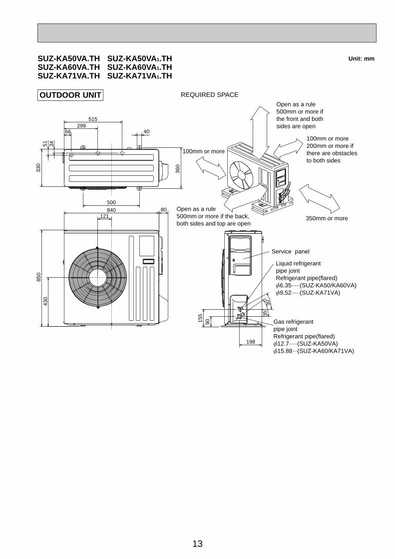
13
Unit: mm
30-
35-
155
90
198
40
515299
66
345133
0
360
850
430
50080
121840
Open as a rule500mm or more ifthe front and bothsides are open
100mm or more 200mm or more if there are obstaclesto both sides
Open as a rule500mm or more if the back,both sides and top are open
350mm or more
100mm or more
Service panel
Gas refrigerant pipe jointRefrigerant pipe(flared)[12.7·····(SUZ-KA50VA)[15.88···(SUZ-KA60/KA71VA)
Liquid refrigerant pipe jointRefrigerant pipe(flared)[6.35·····(SUZ-KA50/KA60VA)[9.52·····(SUZ-KA71VA)
REQUIRED SPACEOUTDOOR UNIT
SUZ-KA50VA.TH SUZ-KA50VA 1.THSUZ-KA60VA.TH SUZ-KA60VA 1.THSUZ-KA71VA.TH SUZ-KA71VA 1.TH
OC322C--1qxp 07.3.12 3:43 PM Page 13
14
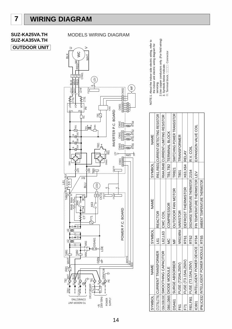
7 WIRING DIAGRAM
OUTDOOR UNIT
SUZ-KA25VA.THSUZ-KA35VA.TH
SY
MB
OL
CT,CT
761,C
T781
C63A
,C63B
,C63C
DB61
,DB6
5
DS
A61
F61
F71
F801
,F90
1
IC80
1
IPM
,IC93
2
SY
MB
OL
L61
L62,
L63
MC
MF
NR63
,NR6
4
RT
61
RT
62
RT
64
RT
65
SY
MB
OL
R61
,R83
1
R64A
,R64
B
TB
1,T
B2
TR
821
T80
1
X63
,X64
21S
4
LEV
N
AM
E
CU
RR
EN
T T
RA
NS
FO
RM
ER
SM
OO
TH
ING
CA
PA
CIT
OR
DIO
DE
MO
DU
LE
SU
RG
E A
BS
OR
BE
R
FU
SE
(T
20A
L250
V)
FU
SE
(T
3.15
AL2
50V
)
FU
SE
(T
3.15
AL2
50V
)
INTE
LLIG
EN
T P
OW
ER
DE
VIC
E
INTE
LLIG
EN
T P
OW
ER
MO
DU
LE
N
AM
E
RE
AC
TO
R
CM
C C
OIL
CO
MP
RE
SS
OR
OU
TD
OO
R F
AN
MO
TO
R
VA
RIS
TO
R
DE
FR
OS
T T
HE
RM
IST
OR
DISC
HARG
E TE
MPER
ATUR
E TH
ERMI
STOR
FIN
TEM
PER
ATU
RE
THER
MIS
TOR
AMBI
ENT
TEM
PERA
TURE
THE
RMIS
TOR
NA
ME
CU
RR
ENT-
DET
ECTI
NG
RES
ISTO
R
CU
RR
EN
T-LI
MIT
ING
RE
SIS
TOR
TE
RM
INA
L B
LOC
K
SWIT
CH
ING
PO
WER
TR
ANSI
STO
R
TR
AN
SF
OR
ME
R
RE
LAY
R.V
. CO
IL
EX
PAN
SIO
N V
ALV
E C
OIL
NO
TE
:1. A
bout
the
indo
or s
ide
elec
tric
wiri
ng,
refe
r to
th
e in
door
uni
t el
ectr
ic w
iring
dia
gram
for
se
rvic
ing.
2.U
se c
oppe
r co
nduc
tors
onl
y. (
For
fie
ld w
iring
)3.
Sym
bols
bel
ow in
dica
te.
/: T
erm
inal
blo
ck,
:
Con
nect
or
MODELS WIRING DIAGRAM
++
+
F61
GR
N~/
N
230V
~
12-2
4V
230V
50H
zCIRC
UIT B
REAK
ER
PE
RE
DBLUW
HIT
E
GRN
/YLW
TB1
POW
ERSU
PPLY
L N
TB2
S3
S1
TO INDDOR UNITCONNECTING
S2
RED
BLU
WHT
NR63
LDE
46
CN
726
CN
727
TB80
0
C63B
PO
WE
R P
.C. B
OA
RD
INV
ER
TE
R P
.C. B
OA
RD
21S4
X63
CN72
1
1 2
L61
TAB6
3
3
LD69
RT61
RT62
RT64
RT65
CN64
2CN
641
CN64
32
12
13
41
2
GRN
23
1CN
601
45
IC80
1F9
01
IC93
2
CN93
13
15
42
12
3CN
932
54
21
3
MF
LD-V
LD-W
LD-U
31W
HT
BLK
RE
DR
ED
V
BLK
WH
T
W
U
wc
CN
61
IPMCT
781
CT76
12
CN
724
LEV
6
R61
N
U V W
PF8
01C6
3C
R831
DB
65
DB61
TR82
1
C63A
T801
LDY
CN
725
BLK
LD70
BLK
L63
NR64
DS
A61
CT
TAB6
1L6
2
X64
4
F71
TAB6
2
BLK
BLU
R64A
R64B
WH
T
OC322C--1qxp 07.3.12 3:43 PM Page 14

15
OUTDOOR UNIT
SUZ-KA25VAH.THSUZ-KA35VAH.TH
SY
MB
OL
CT,CT
761,C
T781
C63A
,C63B
,C63C
DB61
,DB6
5
DS
A61
F61
F71
F801
,F90
1
IC80
1
IPM
,IC93
2
LEV
SY
MB
OL
L61
L62,
L63
MC
MF
NR63
,NR6
4
RT
61
RT
62
RT
64
RT
65
R61
,R83
1
SY
MB
OL
R64A
,R64
B
TB
1,T
B2
TR
821
T80
1
X63,
X64,
X66
21S
4
H 26H
N
AM
E
CU
RR
EN
T T
RA
NS
FO
RM
ER
SM
OO
TH
ING
CA
PA
CIT
OR
DIO
DE
MO
DU
LE
SU
RG
E A
BS
OR
BE
R
FU
SE
(T
20A
L250
V)
FU
SE
(T
3.15
AL2
50V
)
FU
SE
(T
3.15
AL2
50V
)
INTE
LLIG
EN
T P
OW
ER
DE
VIC
E
INTE
LLIG
EN
T P
OW
ER
MO
DU
LE
EX
PAN
SIO
N V
ALV
E C
OIL
N
AM
E
RE
AC
TO
R
CM
C C
OIL
CO
MP
RE
SS
OR
OU
TD
OO
R F
AN
MO
TO
R
VA
RIS
TO
R
DE
FR
OS
T T
HE
RM
IST
OR
DISC
HARG
E TE
MPER
ATUR
E TH
ERMI
STOR
FIN
TEM
PER
ATU
RE
THER
MIS
TOR
AMBI
ENT
TEM
PERA
TURE
THE
RMIS
TOR
CU
RR
ENT-
DET
ECTI
NG
RES
ISTO
R
NA
ME
CU
RR
EN
T-LI
MIT
ING
RE
SIS
TOR
TE
RM
INA
L B
LOC
K
SWIT
CH
ING
PO
WER
TR
ANSI
STO
R
TR
AN
SF
OR
ME
R
RE
LAY
R.V
. CO
IL
DE
FR
OS
T H
EA
TE
R
HE
AT
ER
PR
OT
EC
TO
R
NO
TE
:1. A
bout
the
indo
or s
ide
elec
tric
wiri
ng,
refe
r to
th
e in
door
uni
t el
ectr
ic w
iring
dia
gram
for
se
rvic
ing.
2.U
se c
oppe
r co
nduc
tors
onl
y. (
For
fie
ld w
iring
)3.
Sym
bols
bel
ow in
dica
te.
/: T
erm
inal
blo
ck,
:
Con
nect
or
MODELS WIRING DIAGRAM
IC93
2
F901
CT
43
NR64
NR63
GRN
DSA6
1
LDE
23
14
5CN
601
LDY
GRN
MF
RT65
RT64
RT62
RT61
31
24
5
21
32
12
45
13
CN93
1CN
932
43
12
12
CN64
3CN
641
CN64
231 2
X66
CN72
21 2
YLW
BLK
BLK
BLK
BLK
BLK
BLK
1 2B
LKRE
D
CN
725
6 4
CN
727
CN
726
TB80
0
POW
ER P
.C. B
OAR
DIN
VERT
ER P
.C. B
OAR
D
21S4
X63
CN72
1
1 2IC
801
F801
C63
C
LD-V
LD-W
LD-U
31W
HT
BLK
RE
DRE
D
V
BLK
WHT
W
U
MC
CN
61
IPM
CT78
1
CT76
12
CN
724
LEV
6
R61
N
U V W
P
L61
BLK
R831
TAB6
3
LD69
DB65
DB
61
LD70
TR82
1C63
BC
63A
BLK
T801
L63
F61
TAB6
1L6
2
X64
F71
TAB6
2
BLK
BLU
H26
H
++
+12
-24V
TO INDDOR UNITCONNECTING
PE
CIRC
UIT
BREA
KER
~/N
230V
50H
z
POW
ERSU
PPLY
230V
~
RE
DB
LUW
HIT
E
GRN/
YLW
TB1
L N
R64A
TB2
S3
S1
S2
RED
BLU
WHT
R64B
WHT
OC322C--1qxp 07.3.12 3:43 PM Page 15

16
SUZ-KA50VA.TH SUZ-KA50VA 1.THSUZ-KA60VA.TH SUZ-KA60VA 1.TH
R64B
YLW
230V
~
12-24
V
CN912
CN
663
WHTBLU
NO
ISE
FIL
TE
RP
.C.B
OA
RD
BRN
TO
IND
OO
RU
NIT
CO
NN
EC
TIN
G
RE
DS
3
RT
6521
CN61
13
GR
N/Y
LW
5
PFC
GR
N
LD9
POW
ER B
OAR
DR
T64
2 1CN3
RED
WHT
RS
2
RS
1
R64A
RS
3
RS
4
F801
CN
901
NR
64
ELEC
TRO
NIC
CONT
ROL
P.C.
BOAR
D
CB1
CB2
CB3
HC930
IPM
NF
BLK
BLK
BLK
BLK
WH
TR
ED
YLW
BLU
OR
NP
NK
GR
Y
BLU
WH
T
GRN
GRN
BLUBLU
BLKBLKBLK
BLK
BLK
BLKBLKBLK
BLKBLK
BLK
RE
D
BLU
LCT
2
CT1
SSR61
U
6
CN
795
41
23
78
CN
661
W
CN
4
TB
2
S1
1CN6013
S2
15
67
CN
702
53
21
CN
781
13
CN
701
12
12
CN931
LD1
LD2
T80
1R
937A
R93
7B
CN801
23 1345 12
MF
CN
932
3X
64
51
23
LDE2
12
CT61
TA
B1
F64
F911
LDE1
21S4
PO
WE
R S
UP
PLY
~/N
230
V 5
0Hz
TAB2
N
PE
LTB
1
CIR
CU
ITB
RE
AK
ER
41
RED
YLW
32
RE
DSR
21CN903
21CN902
21CN5
65431CN2
2 7
TA
B4
VM
CW U
V WH
T
RT
61R
T62
RT
68LE
V
MODELS WIRING DIAGRAMOUTDOOR UNIT
:Ter
min
al b
lock
:C
onne
ctor
3.S
ymbo
ls b
elow
indi
cate
.2.
Use
cop
per
cond
ucto
rs o
nly
(for
fiel
d w
iring
). d
iagr
am fo
r se
rvic
ing.
ref
er to
the
indo
or u
nit e
lect
ric w
iring
1.A
bout
the
indo
or s
ide
elec
tric
wiri
ng,
NO
TE
S:
SYM
BOL
NA
ME
SYM
BOL
NA
ME
CU
RR
EN
T T
RA
NS
FO
RM
ER
FU
SE
(T
1AL
250V
)
LEV
EX
PA
NS
ION
VA
LVE
CO
ILL
RE
AC
TO
RIP
MIN
TE
LLIG
EN
T P
OW
ER
MO
DU
LE
CT
61F
US
E (
T2A
L 25
0V)
F64
CT
1, 2
CU
RR
EN
T T
RA
NS
FO
RM
ER
HC
930
INT
ELL
IGE
NT
PO
WE
R M
OD
ULE
F91
1F
801
FU
SE
(T
3.15
AL
250V
)
SM
OO
TH
ING
CA
PA
CIT
OR
CB
1~3
OU
TD
OO
R F
AN
MO
TO
R
PO
WE
R F
AC
TO
R C
ON
TR
OLL
ER
NO
ISE
FIL
TE
R
RT
61DI
SCHA
RGE
TEM
PERA
TURE
THE
RMIS
TOR
RS
1~4
RE
SIS
TO
RR
937A
, BR
ES
IST
OR
MF
MC
CO
MP
RE
SS
OR
R64
A,B
RE
SIS
TO
RP
FC
NF
NR
64V
AR
IST
OR
AMBI
ENT
TEM
PER
ATU
RE
THER
MIS
TOR
SO
LEN
OID
CO
IL R
ELA
Y
21S
4R
.V. C
OIL
X64
RE
LAY
TB
1T
ER
MIN
AL
BLO
CK
TB
2T
ER
MIN
AL
BLO
CK
RT
65F
IN T
EM
PE
RA
TU
RE
TH
ER
MIS
TO
RR
T64
T80
1T
RA
NS
FO
RM
ER
SS
R61
RT
68O
UT
DO
OR
HE
AT
EX
CH
AN
GE
R
TE
MP
ER
AT
UR
E T
HE
RM
IST
OR
DE
FR
OS
T T
HE
RM
IST
OR
RT
62
NA
ME
SYM
BOL
OC322C--1qxp 07.3.12 3:43 PM Page 16

17
SUZ-KA71VA.TH SUZ-KA71VA 1.TH
BLK
CN9021 2
CN9031 2
TA
B4
X64
3
R64
AR
64B
RE
D
2 3
1 4
L
YLW
YLW
RED
230V
~
12-24
V
CN912
CN
663
WHTBLU
NO
ISE
FILT
ER
P.C
.BO
AR
D
BRN
TO IN
DO
OR
UN
ITC
ON
NE
CTI
NG
RE
DS
3
RT
6521
CN61
13
GR
N/Y
LW5
PFC
GR
N
LD9
PO
WE
R B
OA
RD
RT
64
2 1CN3
HP
S
RE
D
RE
D
RED
WHT
RS
2
RS
1R
S3
RS
4
F801
CN
901
NR
64
CN
681
ELEC
TRO
NIC
CONT
ROL
P.C.
BOAR
D
CB1
CB2
CB3
HC930
IPM
NF
BLK
BLK
BLK
BLK
WH
TR
ED
YLW
BLU
OR
NP
NK
GR
Y
BLU
WH
T
GRN
GRN
BLUBLU
BLKBLKBLK
BLK
BLKBLKBLK
BLKBLK
BLK
RE
D
BLU
CT2
CT1
SSR61
U
6
CN
795
41
23
78
CN
661
12
W
CN
4
TB
2
S1
1CN6013
S2
15
67
CN
702
53
21
CN
781
13
CN
701
12
12
CN931
LD1
LD2
T80
1R
937A
R93
7B
CN801
23 1345 12
MF
CN
932
51
23
LDE21
2
CT6
1
TA
B1
F64
F911
LDE1
21S4
PO
WE
R S
UP
PLY
~/N
230
V 5
0Hz
TAB2
N
PE
LTB
1
CIRC
UIT
BREA
KER
SR 21CN5
65431CN2
2 7
VM
CW U
V WH
T
RT
61R
T62
RT
68LE
V
MODEL WIRING DIAGRAMOUTDOOR UNIT
:Ter
min
al b
lock
:C
onne
ctor
3.S
ymbo
ls b
elow
indi
cate
.2.
Use
cop
per
cond
ucto
rs o
nly
(for
fiel
d w
iring
). d
iagr
am fo
r se
rvic
ing.
ref
er to
the
indo
or u
nit e
lect
ric w
iring
1.A
bout
the
indo
or s
ide
elec
tric
wiri
ng,
NO
TE
S:
SYM
BOL
NA
ME
SYM
BOL
NA
ME
CU
RR
EN
T T
RA
NS
FO
RM
ER
FU
SE
(T
1AL
250V
)
LEV
EX
PA
NS
ION
VA
LVE
CO
ILL
RE
AC
TO
RIP
MIN
TE
LLIG
EN
T P
OW
ER
MO
DU
LEH
PS
HIG
H P
RE
SS
UR
E S
WIT
CH
CT
61C
T1,
2C
UR
RE
NT
TR
AN
SF
OR
ME
R
HC
930
INT
ELL
IGE
NT
PO
WE
R M
OD
ULE
F91
1F
801
FU
SE
(T
3.15
AL
250V
)F
64F
US
E (
T2A
L 25
0V)
SM
OO
TH
ING
CA
PA
CIT
OR
CB
1~3
OU
TD
OO
R F
AN
MO
TO
R
PO
WE
R F
AC
TO
R C
ON
TR
OLL
ER
NO
ISE
FIL
TE
R
RT
61DI
SCHA
RGE
TEM
PERA
TURE
THE
RMIS
TOR
RS
1~4
RE
SIS
TO
RR
937A
, BR
ES
IST
OR
MF
MC
CO
MP
RE
SS
OR
R64
A,B
RE
SIS
TO
RP
FC
NF
NR
64V
AR
IST
OR
FIN
TE
MP
ER
AT
UR
E T
HE
RM
IST
OR
SO
LEN
OID
CO
IL R
ELA
Y
21S
4R
.V. C
OIL
X64
RE
LAY
TB
1T
ER
MIN
AL
BLO
CK
TB
2T
ER
MIN
AL
BLO
CK
RT
64
T80
1T
RA
NS
FO
RM
ER
SS
R61
AMBI
ENT
TEM
PER
ATU
RE
THER
MIS
TOR
RT
65
RT
68O
UT
DO
OR
HE
AT
EX
CH
AN
GE
R
TE
MP
ER
AT
UR
E T
HE
RM
IST
OR
DE
FR
OS
T T
HE
RM
IST
OR
RT
62
NA
ME
SYM
BOL
OC322C--1qxp 07.3.12 3:43 PM Page 17

18
REFRIGERANT SYSTEM DIAGRAM8
OUTDOOR UNIT
Unit:mm
Outdoorheatexchanger
Flared connection
DefrostthermistorRT61
DischargetemperaturethermistorRT62
Flared connection
Stop valve(with strainer)
Stop valve(with service port)
Refrigerant flow in cooling
Compressor
4-way valve
Refrigerant flow in heating
Refrigerant pipe [9.52(with heat insulator)
Refrigerant pipe [6.35(with heat insulator)
R.V. coilheating ONcooling OFF
Strainer#100
Capillary tube[3.0[1.8600(2)
Expansionvalve
Ambient temperature thermistorRT65
Muffler
Muffler
Muffler
SUZ-KA25VA.THSUZ-KA25VAH.TH
OUTDOOR UNIT
Unit:mm
Outdoorheatexchanger
Flared connection
DefrostthermistorRT61
DischargetemperaturethermistorRT62
Flared connection
Stop valve(with strainer)
Stop valve(with service port)
Capillary tube[3.0[2.0240
Refrigerant flow in cooling
Compressor
4-way valve
Refrigerant flow in heating
Refrigerant pipe [9.52(with heat insulator)
Refrigerant pipe [6.35(with heat insulator)
Expansionvalve
R.V. coilheating ONcooling OFF
Strainer#100
Muffler
Muffler
Ambient temperature thermistorRT65
Muffler
SUZ-KA35VA.THSUZ-KA35VAH.TH
OC322C--1qxp 07.3.12 3:43 PM Page 18

19
SUZ-KA50VA.TH SUZ-KA50VA 1.THSUZ-KA60VA.TH SUZ-KA60VA 1.THOUTDOOR UNIT
Unit:mm
Outdoorheatexchanger
Flared connection
DefrostthermistorRT61
DischargetemperaturethermistorRT62
Flared connection
Stop valve
Stop valve(with service port)
Capillary tube[3.6[2.450
Refrigerant flow in cooling
Compressor
4-way valve
Refrigerant flow in heating
Refrigerant pipe [12.7 (SUZ-KA50VA)(with heat insulator) [15.88 (SUZ-KA60VA)
Refrigerant pipe [6.35(with heat insulator)
LEVR.V. coilheating ONcooling OFF
Muffler#100
Strainer#100Receiver
Outdoor heat exchanger temperaturethermistorRT68
AmbienttemperaturethermistorRT65
Strainer#100
SUZ-KA71VA.TH SUZ-KA71VA 1.THOUTDOOR UNIT
Unit:mm
Outdoorheatexchanger
Flared connection DefrostthermistorRT61
DischargetemperaturethermistorRT62
Flared connection
Stop valve
Stop valve(with service port)
Capillary tube[3.6[2.450
Capillary tube[1.8[0.61000
Refrigerant flow in cooling
Compressor
4-way valve
Refrigerant flow in heating
Refrigerant pipe [15.88(with heat insulator)
Refrigerant pipe [9.52(with heat insulator)
LEVR.V. coilheating ONcooling OFF
Oil separator High-pressureswitch
Strainer#100Receiver
Outdoor heat exchanger temperature thermistorRT68
Strainer#100
Strainer#100 Ambient
temperaturethermistorRT65
OC322C--1qxp 07.3.12 3:43 PM Page 19

20
ADDITIONAL REFRIGERANT CHARGE (R410A:g)
Outdoor unit precharged
900
1,050
14m
270
270
7m
0
0
6m
0
0
5m
0
0
11m
180
180
Models Refrigerant piping length (one way)
Calculation : Xg=30g/mo(Refrigerant piping length(m) - 5)
8m
90
90
9m
120
120
10m
150
150
12m
210
210
13m
240
240
15m
300
300
20m
450
450
SUZ-KA25VA.THSUZ-KA25VAH.TH
SUZ-KA35VA.THSUZ-KA35VAH.TH
Refrigerant PipingMax. length A
w Height difference should be within 12m regardless of which unit, indoor or outdoor position is high.
w Max. Heightdifference 12m
Indoorunit (SLZ/SEZ)
Outdoor unit
MAX. HEIGHT DIFFERENCE
Refrigerant piping
Max. length : m
A
20
Gas
9.52
Liquid
6.35
Piping size O.D : mmModels
SUZ-KA25VA.THSUZ-KA35VA.TH
SUZ-KA25VAH.THSUZ-KA35VAH.TH
SUZ-KA25VA.TH SUZ-KA25VAH.THSUZ-KA35VA.TH SUZ-KA35VAH.TH
MAX. REFRIGERANT PIPING LENGTH
OC322C--1qxp 07.3.12 3:43 PM Page 20

21
Refrigerant PipingMax. length A
w Height difference should be within 30m regardless of which unit, indoor or outdoor position is high. Max. Height difference of SUZ-KA50/60/71VA.TH : 15m
SUZ-KA50/60/71VA1.TH : 30m
w Max. Heightdifference 30m
Indoorunit
Outdoor unit
(SLZ/SEZ)
MAX. HEIGHT DIFFERENCE
Refrigerant piping
Max. length : m
A
30
Gas
12.7
15.88
Liquid
6.35
9.52
SUZ-KA50VA.THSUZ-KA50VA1.TH
SUZ-KA60VA.THSUZ-KA60VA1.TH
SUZ-KA71VA.TH SUZ-KA71VA1.TH
Model Piping size O.D : mm
Refrigerant piping length (one way)Outdoor unitprecharged 15m
160
160
20m
260
260
25m
360
360
30m
460
460
7m
0
0
10m
60
60
Model
SUZ-KA50VA.THSUZ-KA50VA1.TH
SUZ-KA60VA.THSUZ-KA60VA1.TH
1,600
1,800
ADDITIONAL REFRIGERANT CHARGE(R410A : g)
Calculation : Xg=20g/m (Refrigerant piping length (m)–7)
SUZ-KA50VA.TH SUZ-KA50VA 1.THSUZ-KA60VA.TH SUZ-KA60VA 1.THSUZ-KA71VA.TH SUZ-KA71VA 1.TH
MAX. REFRIGERANT PIPING LENGTH
Outdoor unitprecharged
2,000 0 165 440 715 990 1,265
Refrigerant piping length (one way)
15m10m7mModel
SUZ-KA71VA.THSUZ-KA71VA1.TH
20m 25m 30m
Calculation : Xg=55g/mo(Refrigerant piping length(m)-7)
OC322C--1qxp 07.3.12 3:43 PM Page 21
22
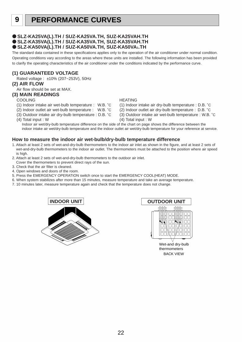
PERFORMANCE CURVES9
SLZ-KA25VA(L).TH / SUZ-KA25VA.TH, SUZ-KA25VAH.TH SLZ-KA35VA(L).TH / SUZ-KA35VA.TH, SUZ-KA35VAH.TH SLZ-KA50VA(L).TH / SUZ-KA50VA.TH, SUZ-KA50VA 1.THThe standard data contained in these specifications applies only to the operation of the air conditioner under normal condition.Operating conditions vary according to the areas where these units are installed. The following information has been providedto clarify the operating characteristics of the air conditioner under the conditions indicated by the performance curve.
(1) GUARANTEED VOLTAGERated voltage : ±10% (207~253V), 50Hz
(2) AIR FLOWAir flow should be set at MAX.
(3) MAIN READINGSCOOLING HEATING(1) Indoor intake air wet-bulb temperature : W.B. ˚C (1) Indoor intake air dry-bulb temperature : D.B. ˚C(2) Indoor outlet air wet-bulb temperature : W.B. ˚C (2) Indoor outlet air dry-bulb temperature : D.B. ˚C(3) Outdoor intake air dry-bulb temperature : D.B. ˚C (3) Outdoor intake air wet-bulb temperature : W.B. ˚C(4) Total input : W (4) Total input : W
Indoor air wet/dry-bulb temperature difference on the side of the chart on page shows the difference between the indoor intake air wet/dry-bulb temperature and the indoor outlet air wet/dry-bulb temperature for your reference at service.
How to measure the indoor air wet-bulb/dry-bulb temperature difference1. Attach at least 2 sets of wet-and-dry-bulb thermometers to the indoor air inlet as shown in the figure, and at least 2 sets of
wet-and-dry-bulb thermometers to the indoor air outlet. The thermometers must be attached to the position where air speedis high.
2. Attach at least 2 sets of wet-and-dry-bulb thermometers to the outdoor air inlet.Cover the thermometers to prevent direct rays of the sun.
3. Check that the air filter is cleaned.4. Open windows and doors of the room.5. Press the EMERGENCY OPERATION switch once to start the EMERGENCY COOL(HEAT) MODE.6. When system stabilizes after more than 15 minutes, measure temperature and take an average temperature.7. 10 minutes later, measure temperature again and check that the temperature does not change.
Wet-and dry-bulbthermometers
BACK VIEW
INDOOR UNIT OUTDOOR UNIT
OC322C--1qxp 07.3.12 3:43 PM Page 22

23
Ind
oo
r ai
r W
et-b
ulb
tem
per
atu
red
iffe
ren
ce (
deg
ree)
10.8
10.0
9.2
8.5
7.7
6.9
SU
Z-K
A50
VA
1.T
HR
ated
freq
uenc
y 75
Hz
Outdoor intake air Dry-bulb temperature (:)
-10-15 -5 0 5 10 15 20 25 30 35 40 45 46
Outdoor intake air Dry-bulb temperature (:)
Indoor intake air Wet-bulb temperature(:)
-15 -10 -5 0 5 10 15 20 25 30 35 40 45 46
Ind
oo
r ai
r W
et-b
ulb
tem
per
atu
red
iffe
ren
ce (
deg
ree)
8.4
7.8
7.2
6.6
6.0
5.4
SUZ-
KA
35VA
(H).T
HR
ated
freq
uenc
y 73
Hz
Outdoor intake air Dry-bulb temperature (:)
-10 -5 0 5 10 15 20 25 30 35 40 45 46
Outdoor intake air Dry-bulb temperature (:)
Indoor intake air Wet-bulb temperature(:)
-10 -5 0 5 10 15 20 25 30 35 40 45 46
Ind
oo
r ai
r W
et-b
ulb
tem
per
atu
red
iffe
ren
ce (
deg
ree)
SUZ-
KA
25VA
(H).T
H
6.4
5.9
5.4
5.0
4.5
4.1
Rat
ed fr
eque
ncy
58H
z
Outdoor intake air Dry-bulb temperature (:) Outdoor intake air Dry-bulb temperature (:)
Indoor intake air Wet-bulb temperature(:)Indoor intake air Wet-bulb temperature(:)
Indoor intake air Wet-bulb temperature(:)
Indoor intake air Wet-bulb temperature(:)
-10 -5 0 5 10 15 20 25 30 35 40 45 46-10 -5 0 5 10 15 20 25 30 35 40 45 46
OC322C--1qxp 07.3.12 3:43 PM Page 23

24
OUTDOOR LOW PRESSURE AND OUTDOOR UNIT CURRENT
0 50 100 150(Hz)0.0
0.5
1.0
1.5Correction of Cooling capacity
Cap
acity
cor
rect
ion
fact
ors
The operational frequency of compressor
0 50 100 150(Hz)0.0
0.5
1.0
1.5Correction of Cooling capacity
Cap
acity
cor
rect
ion
fact
ors
The operational frequency of compressor
Correction of Cooling total input
Inpu
t cor
rect
ion
fact
ors
The operational frequency of compressor
0 50 100 150(Hz)0.0
0.5
1.0
1.5
2.0
1.5
1.0
0.5
0.00 50 100 150(Hz)
Correction of Heating capacity
Cap
acity
cor
rect
ion
fact
ors
The operational frequency of compressor
2.0
1.5
1.0
0.5
0.0
Correction of Heating total inputIn
put c
orre
ctio
n fa
ctor
s
The operational frequency of compressor
0 50 100 150(Hz)
2.0
1.5
1.0
0.5
0.00 50 100 150(Hz)
Correction of Heating capacity
Cap
acity
cor
rect
ion
fact
ors
The operational frequency of compressor
Correction of Heating total input
The operational frequency of compressor
0 50 100 150(Hz)
2.0
1.5
1.0
0.5
0.0
Inpu
t cor
rect
ion
fact
ors
The operational frequency of compressor
Correction of Cooling total input
0 50 100 150(Hz)
2.0
1.5
1.0
0.5
0.0
Inpu
t cor
rect
ion
fact
ors
0 50 100 150(Hz)0.0
0.5
1.0
1.5Correction of Cooling capacity
Cap
acity
cor
rect
ion
fact
ors
The operational frequency of compressor
Correction of Cooling total input
Inpu
t cor
rect
ion
fact
ors
The operational frequency of compressor
0 50 100 150(Hz)0.0
0.5
1.0
1.5 2.5
2.0
1.5
1.0
0.5
0.0
Correction of Heating total input
Inpu
t cor
rect
ion
fact
ors
The operational frequency of compressor
0 50 100 150(Hz)
2.0
1.5
1.0
0.5
0.00 50 100 150(Hz)
Correction of Heating capacity
Cap
acity
cor
rect
ion
fact
ors
The operational frequency of compressor
SUZ-KA25VA(H).TH
SUZ-KA35VA(H).TH SUZ-KA35VA(H).TH SUZ-KA35VA(H).TH SUZ-KA35VA(H).TH
SUZ-KA25VA(H).TH SUZ-KA25VA(H).TH SUZ-KA25VA(H).TH
SUZ-KA50VA(1).TH SUZ-KA50VA(1).TH SUZ-KA50VA(1).TH SUZ-KA50VA(1).TH
<How to operate fixed-frequency operation (Test run operation)> 1. Press the EMERGENCY OPERATION switch or the Test button to COOL or HEAT mode.2. Test run operation starts and continues to operate for 30 minutes.3. Compressor starts at rated frequency in COOL mode or 58Hz in HEAT mode.4. Indoor fan operates at High speed.5. After 30 minutes, test run operation finishes and EMERGENCY OPERATION starts.6. To cancel test run operation (EMERGENCY OPERATION), press the EMERGENCY OPERATION switch or the ON/OFF
button on remote controller.
NOTE : The unit of pressure has been changed to MPa on the international system of units (SI unit system).The conversion factor is: 1(MPa [Gauge]) =10.2(kgf/ ff [Gauge])
20.8
19.2
17.6
16.0
14.4
12.8
11.2
9.6
23.9
22.1
20.2
18.4
16.5
14.7
12.9
11.0
Ind
oo
r ai
r D
ry-b
ulb
tem
per
atu
red
iffe
ren
ce (
deg
ree)
Indoor intake air D
ry-bulb temperature (:)
Outdoor intake air Wet-bulb temperature (:) Outdoor intake air Wet-bulb temperature (:)
Indoor intake air Dry-bulb temperature (:)
SU
Z-K
A25
VA
(H).T
HR
ated
freq
uenc
y 77
Hz
SU
Z-K
A35
VA
(H).T
HR
ated
freq
uenc
y 77
Hz
28.2
26.0
23.9
21.7
19.5
17.4
15.2
13.0
SU
Z-K
A50
VA
.TH
Rat
ed fr
eque
ncy
65H
z
NOTE:The above curves are for the heating operation without any frost.
OC322C--1qxp 07.3.12 3:43 PM Page 24

25
Out
door
uni
t cur
rent
(A)
15 2050
2560
3070 (%)
35(˚C)3
3.5
4
4.5
5
73Hz
3218
Ambient temperature(˚C) Ambient humidity(%)
SUZ-KA35VA(H).TH
15 2050
2560
3070 (%)
35(˚C)2
2.5
3
3.5
4
58Hz
3218
Out
door
uni
t cur
rent
(A)
Ambient temperature(˚C) Ambient humidity(%)
SUZ-KA25VA(H).TH
(MPa [Gauge]) (kgf/F [Gauge])
18 3215 2050
2560
3070 (%)
35(˚C)0.2
0.4
0.6
0.8
1.0
1.258Hz
2
4
6
8
10
12
14 1.4
Ambient temperature(˚C) Ambient humidity(%)
Out
door
low
pre
ssur
e
SUZ-KA25VA(H).TH(MPa [Gauge]) (kgf/F [Gauge])
18 3215 2050
2560
3070 (%)
35(˚C)0.2
0.4
0.6
0.8
1.0
1.273Hz
1.4
Ambient temperature(˚C) Ambient humidity(%)
Out
door
low
pre
ssur
e
SUZ-KA35VA(H).TH
2
4
6
8
10
12
14
Out
door
uni
t cur
rent
(A)
15 2050
2560
3070 (%)
35(˚C)5.0
6.0
7.0
8.0
9.0
75Hz
3218
Ambient temperature(˚C) Ambient humidity(%)
SUZ-KA50VA(1).TH
(MPa [Gauge]) (kgf/F [Gauge])
18 3215 2050
2560
3070 (%)
35(˚C)0.2
0.4
0.6
0.8
1.0
1.2 75Hz
1.4
Ambient temperature(˚C) Ambient humidity(%)
Out
door
low
pre
ssur
e
SUZ-KA50VA(1).TH
2
4
6
8
10
12
14
OUTDOOR LOW PRESSURE AND OUTDOOR UNIT CURRENTCOOL operation1 Both indoor and outdoor unit are under the
same temperature/humidity condition.2 Air flow : High speed3 Operational frequency : 58Hz(SUZ-KA25VA(H).TH)
73Hz(SUZ-KA35VA(H).TH)75Hz(SUZ-KA50VA(1).TH)
Dry-bulb temperature Relative humidity(%)
20 50
25 60
30 70
HEAT operationCondition indoor: Dry bulb temperature 20.0°C
Wet bulb temperature 14.5°CCondition outdoor: Dry bulb temperature 2,7,15,20.0°C
Wet bulb temperature 1,6,12,14.5°C
SUZ-KA25VA(H).TH
Out
door
uni
t cur
rent
(A
)
Ambient temperature(˚C)
3.0
2.5
2.0
1.5
1.0
0.5
0.02 5 10 15 20 25(:)
58Hz
SUZ-KA35VA(H).TH
Out
door
uni
t cur
rent
(A
)
Ambient temperature(˚C)
4.0
3.5
3.0
2.5
2.0
1.5
1.02 5 10 15 20 25(:)
58Hz
SUZ-KA50VA(1).TH
Out
door
uni
t cur
rent
(A
)
Ambient temperature(˚C)
7.0
6.0
5.0
4.0
3.0
2.0
1.02 5 10 15 20 25(:)
58Hz
OC322C--1qxp 07.3.12 3:43 PM Page 25

26
SEZ-KC25VA.W / SUZ-KA25VA.TH, SUZ-KA25VAH.TH SEZ-KA35VA.TH / SUZ-KA35VA.TH, SUZ-KA35VAH.TH SEZ-KA50VA.TH / SUZ-KA50VA.TH, SUZ-KA50VA 1.TH SEZ-KA60VA.TH / SUZ-KA60VA.TH, SUZ-KA60VA 1.TH SEZ-KA71VA.TH / SUZ-KA71VA.TH, SUZ-KA71VA 1.TH
The standard data contained in these specifications applies only to the operation of the air conditioner under normal condition.Operating conditions vary according to the areas where these units are installed. The following information has been provided to clarify the operating characteristics of the air conditioner under the conditions indicated by the performance curve.
(1) GUARANTEED VOLTAGERated voltage : ±10% (207~253V), 50Hz
(2) AIR FLOWAir flow should be set at MAX.
(3) MAIN READINGSCOOLING HEATING(1) Indoor intake air wet-bulb temperature : W.B.˚C (1) Indoor intake air dry-bulb temperature : D.B.˚C(2) Indoor outlet air wet-bulb temperature : W.B.˚C (2) Indoor outlet air dry-bulb temperature : D.B.˚C(3) Outdoor intake air dry-bulb temperature : D.B.˚C (3) Outdoor intake air wet-bulb temperature : W.B.˚C(4) Total input : W (4) Total input : W
Indoor air wet/dry-bulb temperature difference on the side of the chart on page shows the difference between the indoor intake air wet/dry-bulb temperature and the indoor outlet air wet/dry-bulb temperature for your reference at service.
How to measure the indoor air wet-bulb/dry-bulb temperature difference1. Attach at least 2 sets of wet-and-dry-bulb thermometers to the indoor air inlet as shown in the figure, and at least 2 sets of
wet-and-dry-bulb thermometers to the indoor air outlet. The thermometers must be attached to the position where air speed is high.
2. Attach at least 2 sets of wet-and-dry-bulb thermometers to the outdoor air inlet.Cover the thermometers to prevent direct rays of the sun.
3. Check that the air filter is cleaned.4. Open windows and doors of the room.5. Press the TEST button twice to start the COOL(HEAT) MODE.6. When system stabilizes after more than 15 minutes, measure temperature and take an average temperature.7. 10 minutes later, measure temperature again and check that the temperature does not change.
Air outlet
Air inlet
Wet-and dry-bulbthermometers
Wet-and dry-bulbthermometersBACK VIEW
INDOOR UNIT OUTDOOR UNIT
w The picture is SEZ-KA35, 50, 60, 71VA.SEZ-KC25VA is similar to SEZ-KA35, 50, 60, 71VA.
OC322C--1qxp 07.3.12 3:43 PM Page 26

27
8.4
7.8
7.2
6.6
6.0
5.4
8.6
8.0
7.4
6.8
6.2
5.5
10.5
9.6
8.8
7.9
7.1
6.3
8.4
7.8
7.2
6.6
6.0
5.4
7.9
7.3
6.7
6.2
5.6
5.1
Ind
oo
r ai
r W
et-b
ulb
tem
per
atu
red
iffe
ren
ce (
deg
ree)
SU
Z-K
A50
VA
1.T
HR
ated
freq
uenc
y 80
Hz
SU
Z-K
A60
VA
1.T
HR
ated
freq
uenc
y 86
Hz
SU
Z-K
A71
VA
1.T
HR
ated
freq
uenc
y 61
Hz
Outdoor intake air Dry-bulb temperature (:)
-10-15 -5 0 5 10 15 20 25 30 35 40 45 46
Outdoor intake air Dry-bulb temperature (:)
Indoor intake air Wet-bulb temperature(:)
-15 -10 -5 0 5 10 15 20 25 30 35 40 45 46
Ind
oo
r ai
r W
et-b
ulb
tem
per
atu
red
iffe
ren
ce (
deg
ree)
SUZ-
KA
35VA
(H).T
HR
ated
freq
uenc
y 73
Hz
Outdoor intake air Dry-bulb temperature (:)
-10 -5 0 5 10 15 20 25 30 35 40 45 46
Outdoor intake air Dry-bulb temperature (:)
Indoor intake air Wet-bulb temperature(:)
-10 -5 0 5 10 15 20 25 30 35 40 45 46
Ind
oo
r ai
r W
et-b
ulb
tem
per
atu
red
iffe
ren
ce (
deg
ree)
SUZ-
KA
25VA
(H).T
HR
ated
freq
uenc
y 63
Hz
Outdoor intake air Dry-bulb temperature (:) Outdoor intake air Dry-bulb temperature (:)
Indoor intake air Wet-bulb temperature(:)
-10 -5 0 5 10 15 20 25 30 35 40 45 46-10 -5 0 5 10 15 20 25 30 35 40 45 46
Indoor intake air Wet-bulb temperature(:)
Indoor intake air Wet-bulb temperature(:)
Indoor intake air Wet-bulb temperature(:)
OC322C--1qxp 07.3.12 3:43 PM Page 27

28
25.2
23.2
21.3
19.4
17.4
15.5
13.6
11.6
Ind
oo
r ai
r D
ry-b
ulb
tem
per
atu
red
iffe
ren
ce (
deg
ree)
Indoor intake air D
ry-bulb temperature (:)
Outdoor intake air Wet-bulb temperature (:) Outdoor intake air Wet-bulb temperature (:)
Indoor intake air Dry-bulb temperature (:)
SU
Z-K
A25
VA
(H).T
HR
ated
freq
uenc
y 77
Hz
22.7
20.9
19.2
17.4
15.7
14.0
12.2
10.5
SU
Z-K
A35
VA
(H).T
HR
ated
freq
uenc
y 77
Hz
24.5
22.6
20.7
18.9
17.0
15.1
13.2
11.3
SU
Z-K
A50
VA
(1).T
HR
ated
freq
uenc
y 80
Hz
25.3
23.3
21.4
19.4
17.5
15.5
13.6
11.7
SU
Z-K
A60
VA
(1).T
HR
ated
freq
uenc
y 96
Hz
Ind
oo
r ai
r D
ry-b
ulb
tem
per
atu
red
iffe
ren
ce (
deg
ree)
Indoor intake air D
ry-bulb temperature (:)
Outdoor intake air Wet-bulb temperature (:) Outdoor intake air Wet-bulb temperature (:)
Indoor intake air Dry-bulb temperature (:)
25.3
23.3
21.4
19.4
17.5
15.5
13.6
11.7
SU
Z-K
A71
VA
(1).T
HR
ated
freq
uenc
y 61
Hz
Heating capacity
Heating capacity
Total input (heating)
Total input (heating)
NOTE:The above curves are for the heating operation without any frost.
OC322C--1qxp 07.3.12 3:43 PM Page 28

29
SUZ-KA25VA(H).TH SUZ-KA25VA(H).TH SUZ-KA25VA(H).TH SUZ-KA25VA(H).TH
SUZ-KA35VA(H).TH SUZ-KA35VA(H).TH SUZ-KA35VA(H).TH SUZ-KA35VA(H).TH
SUZ-KA50VA(1).TH SUZ-KA50VA(1).TH SUZ-KA50VA(1).TH SUZ-KA50VA(1).TH
SUZ-KA60VA(1).TH SUZ-KA60VA(1).TH SUZ-KA60VA(1).TH SUZ-KA60VA(1).TH
SUZ-KA71VA(1).TH SUZ-KA71VA(1).TH SUZ-KA71VA(1).TH SUZ-KA71VA(1).TH
0 50 100 150(Hz)0.0
0.5
1.0
1.5Correction of Cooling capacity
Cap
acity
cor
rect
ion
fact
ors
The operational frequency of compressor
Correction of Cooling total input
Inpu
t cor
rect
ion
fact
ors
The operational frequency of compressor
2.0
1.5
1.0
0.5
0.0
Correction of Heating total input
Inpu
t cor
rect
ion
fact
ors
The operational frequency of compressor
0 50 100 150(Hz)
2.0
1.5
1.0
0.5
0.00 50 100 150(Hz)
2.0
1.5
1.0
0.5
0.00 50 100 150(Hz)
Correction of Heating capacity
Cap
acity
cor
rect
ion
fact
ors
The operational frequency of compressor
0 50 100 150(Hz)0.0
0.5
1.0
1.5Correction of Cooling capacity
Cap
acity
cor
rect
ion
fact
ors
The operational frequency of compressor
Correction of Cooling total input
Inpu
t cor
rect
ion
fact
ors
The operational frequency of compressor
0 50 100 150(Hz)0.0
0.5
1.0
1.5 2.0
1.5
1.0
0.5
0.0
Correction of Heating total input
Inpu
t cor
rect
ion
fact
ors
The operational frequency of compressor
0 50 100 150(Hz)
2.0
1.5
1.0
0.5
0.00 50 100 150(Hz)
Correction of Heating capacity
Cap
acity
cor
rect
ion
fact
ors
The operational frequency of compressor
OC322C--1qxp 07.3.12 3:43 PM Page 29

30
15 2050
2560
3070 (%)
35(˚C)6
7
8
9
10
80Hz
3218
Out
door
uni
t cur
rent
(A)
Ambient temperature(˚C) Ambient humidity(%)
SUZ-KA50VA(1).TH
(MPa [Gauge]) (kgf/F [Gauge])
18 3215 2050
2560
3070 (%)
35(˚C)0.2
0.4
0.6
0.8
1.0
1.280Hz
1.4
Ambient temperature(˚C) Ambient humidity(%)
Out
door
low
pre
ssur
e
SUZ-KA50VA(1).TH
2
4
6
8
10
12
14
15 2050
2560
3070 (%)
35(˚C)3
3.5
4
4.5
5
73Hz
3218
Out
door
uni
t cur
rent
(A)
Ambient temperature(˚C) Ambient humidity(%)
SUZ-KA35VA(H).TH
(MPa [Gauge]) (kgf/F [Gauge])
18 3215 2050
2560
3070 (%)
35(˚C)0.2
0.4
0.6
0.8
1.0
1.273Hz
1.4
Ambient temperature(˚C) Ambient humidity(%)
Out
door
low
pre
ssur
e
SUZ-KA35VA(H).TH
2
4
6
8
10
12
14(MPa [Gauge]) (kgf/F [Gauge])
18 3215 2050
2560
3070 (%)
35(˚C)0.2
0.4
0.6
0.8
1.0
1.2 63Hz
1.4
Ambient temperature(˚C) Ambient humidity(%)
Out
door
low
pre
ssur
e
SUZ-KA25VA(H).TH
2
4
6
8
10
12
14
15 2050
2560
3070 (%)
35(˚C)4
6
8
10
1287Hz
3218
Out
door
uni
t cur
rent
(A)
Ambient temperature(˚C) Ambient humidity(%)
SUZ-KA60VA(1).TH
(MPa [Gauge]) (kgf/F [Gauge])
18 3215 2050
2560
3070 (%)
35(˚C)0.2
0.4
0.6
0.8
1.0
1.2
87Hz1.4
Ambient temperature(˚C) Ambient humidity(%)
Out
door
low
pre
ssur
e
SUZ-KA60VA(1).TH
2
4
6
8
10
12
14
15 2050
2560
3070 (%)
35(˚C)2
2.5
3
3.5
4
63Hz
3218
Out
door
uni
t cur
rent
(A)
Ambient temperature(˚C) Ambient humidity(%)
SUZ-KA25VA(H).TH
61Hz
(MPa [Gauge]) (kgf/F [Gauge])
18 3215 2050
2560
3070 (%)
35(˚C)0.2
0.4
0.6
0.8
1.0
1.2
1.4
Ambient temperature(˚C) Ambient humidity(%)
Out
door
low
pre
ssur
e
SUZ-KA71VA(1).TH
2
4
6
8
10
12
14
Ambient temperature(˚C) Ambient humidity(%)
15 2050
2560
3070 (%)
35(˚C)4
6
8
10
12
61Hz
3218
Out
door
uni
t cur
rent
(A)
SUZ-KA71VA(1).TH
Dry-bulb temperature Relative humidity(%)
20 50
25 60
30 70
OUTDOOR LOW PRESSURE AND OUTDOOR UNIT CURRENT<How to operate fixed-frequency operation (Test run operation)>
1. Press the TEST button to COOL or HEAT mode.2. Test run operation starts and continue to operate for 30 minutes.3. Compressor starts at rated frequency in COOL mode or 58Hz in HEAT mode.4. Indoor fan operates at High speed.5. After 30 minutes, test run operation finishes and EMERGENCY OPERATION starts.6. To cancel test run operation (EMERGENCY OPERATION), press the ON/OFF button on remote controller.NOTE : The unit of pressure has been changed to MPa on the international system of units (SI unit system).
The conversion factor is: 1(MPa [Gauge]) =10.2(kgf/ ff [Gauge])
OUTDOOR LOW PRESSURE AND OUTDOOR UNIT CURRENTCOOL operation1 Both indoor and outdoor unit are under the
same temperature/humidity condition.2 Air flow : High speed3 Operational frequency : 63Hz(SUZ-KA25VA(H).TH)
73Hz(SUZ-KA35VA(H).TH)80Hz(SUZ-KA50VA(1).TH)87Hz(SUZ-KA60VA(1).TH)61Hz(SUZ-KA71VA(1).TH)
OC322C--1qxp 07.3.12 3:43 PM Page 30

31
HEAT operationCondition indoor: Dry bulb temperature 20.0°C
Wet bulb temperature 14.5°CCondition outdoor: Dry bulb temperature 2,7,15,20.0°C
Wet bulb temperature 1,6,12,14.5°C
SUZ-KA25VA(H).TH
Out
door
uni
t cur
rent
(A
)
Ambient temperature(˚C)
4.0
3.5
3.0
2.5
2.0
1.5
1.02 5 10 15 20 25(:)
58Hz
SUZ-KA71VA(1).TH
Out
door
uni
t cur
rent
(A
)
Ambient temperature(˚C)
13.0
12.0
11.0
10.0
9.0
8.0
7.02 5 10 15 20 25(:)
58Hz
SUZ-KA35VA(H).TH
Out
door
uni
t cur
rent
(A
)
Ambient temperature(˚C)
4.0
3.5
3.0
2.5
2.0
1.5
1.02 5 10 15 20 25(:)
58Hz
SUZ-KA50VA(1).TH
Out
door
uni
t cur
rent
(A
)
Ambient temperature(˚C)
7.0
6.0
5.0
4.0
3.0
2.0
1.02 5 10 15 20 25(:)
58Hz 58Hz
SUZ-KA60VA(1).TH
Out
door
uni
t cur
rent
(A
)
Ambient temperature(˚C)
7.0
6.0
5.0
4.0
3.0
2.0
1.02 5 10 15 20 25(:)
OC322C--2qxp 07.3.12 3:43 PM Page 31

32
2.94 2.00 0.68 552 2.81 1.91 0.68 580 2.70 1.84 0.68 607 2.60 1.77 0.68 6353.06 1.72 0.56 580 2.94 1.65 0.56 614 2.85 1.60 0.56 628 2.75 1.54 0.56 6562.94 2.12 0.72 552 2.81 2.03 0.72 580 2.70 1.94 0.72 607 2.60 1.87 0.72 6353.06 1.84 0.60 580 2.94 1.76 0.60 614 2.85 1.71 0.60 628 2.75 1.65 0.60 6563.19 1.53 0.48 600 3.08 1.48 0.48 638 3.00 1.44 0.48 656 2.88 1.38 0.48 6832.94 2.23 0.76 552 2.81 2.14 0.76 580 2.70 2.05 0.76 607 2.60 1.98 0.76 6353.06 1.96 0.64 580 2.94 1.88 0.64 614 2.85 1.82 0.64 628 2.75 1.76 0.64 6563.19 1.66 0.52 600 3.08 1.60 0.52 638 3.00 1.56 0.52 656 2.88 1.50 0.52 6832.94 2.35 0.80 552 2.81 2.25 0.80 580 2.70 2.16 0.80 607 2.60 2.08 0.80 6353.06 2.08 0.68 580 2.94 2.00 0.68 614 2.85 1.94 0.68 628 2.75 1.87 0.68 6563.19 1.79 0.56 600 3.08 1.72 0.56 638 3.00 1.68 0.56 656 2.88 1.61 0.56 6833.35 1.47 0.44 628 3.23 1.42 0.44 662 3.15 1.39 0.44 683 3.05 1.34 0.44 7183.06 2.21 0.72 580 2.94 2.12 0.72 614 2.85 2.05 0.72 628 2.75 1.98 0.72 6563.19 1.91 0.60 600 3.08 1.85 0.60 638 3.00 1.80 0.60 656 2.88 1.73 0.60 6833.35 1.61 0.48 628 3.23 1.55 0.48 662 3.15 1.51 0.48 683 3.05 1.46 0.48 7182.94 2.59 0.88 552 2.81 2.48 0.88 580 2.70 2.38 0.88 607 2.60 2.29 0.88 6353.06 2.33 0.76 580 2.94 2.23 0.76 614 2.85 2.17 0.76 628 2.75 2.09 0.76 6563.19 2.04 0.64 600 3.08 1.97 0.64 638 3.00 1.92 0.64 656 2.88 1.84 0.64 6833.35 1.74 0.52 628 3.23 1.68 0.52 662 3.15 1.64 0.52 683 3.05 1.59 0.52 7183.45 1.38 0.40 662 3.35 1.34 0.40 697 3.30 1.32 0.40 718 3.20 1.28 0.40 7382.94 2.70 0.92 552 2.81 2.59 0.92 580 2.70 2.48 0.92 607 2.60 2.39 0.92 6353.06 2.45 0.80 580 2.94 2.35 0.80 614 2.85 2.28 0.80 628 2.75 2.20 0.80 6563.19 2.17 0.68 600 3.08 2.09 0.68 638 3.00 2.04 0.68 656 2.88 1.96 0.68 6833.35 1.88 0.56 628 3.23 1.81 0.56 662 3.15 1.76 0.56 683 3.05 1.71 0.56 7183.45 1.52 0.44 662 3.35 1.47 0.44 697 3.30 1.45 0.44 718 3.20 1.41 0.44 7382.94 2.82 0.96 552 2.81 2.70 0.96 580 2.70 2.59 0.96 607 2.60 2.50 0.96 6353.06 2.57 0.84 580 2.94 2.47 0.84 614 2.85 2.39 0.84 628 2.75 2.31 0.84 6563.19 2.30 0.72 600 3.08 2.21 0.72 638 3.00 2.16 0.72 656 2.88 2.07 0.72 6833.35 2.01 0.60 628 3.23 1.94 0.60 662 3.15 1.89 0.60 683 3.05 1.83 0.60 7183.45 1.66 0.48 662 3.35 1.61 0.48 697 3.30 1.58 0.48 718 3.20 1.54 0.48 7382.94 2.94 1.00 552 2.81 2.81 1.00 580 2.70 2.70 1.00 607 2.60 2.60 1.00 6353.06 2.70 0.88 580 2.94 2.59 0.88 614 2.85 2.51 0.88 628 2.75 2.42 0.88 6563.19 2.42 0.76 600 3.08 2.34 0.76 638 3.00 2.28 0.76 656 2.88 2.19 0.76 6833.35 2.14 0.64 628 3.23 2.06 0.64 662 3.15 2.02 0.64 683 3.05 1.95 0.64 7183.45 1.79 0.52 662 3.35 1.74 0.52 697 3.30 1.72 0.52 718 3.20 1.66 0.52 7382.94 3.06 1.04 552 2.81 2.93 1.04 580 2.70 2.81 1.04 607 2.60 2.70 1.04 6353.06 2.82 0.92 580 2.94 2.70 0.92 614 2.85 2.62 0.92 628 2.75 2.53 0.92 6563.19 2.55 0.80 600 3.08 2.46 0.80 638 3.00 2.40 0.80 656 2.88 2.30 0.80 6833.35 2.28 0.68 628 3.23 2.19 0.68 662 3.15 2.14 0.68 683 3.05 2.07 0.68 7183.45 1.93 0.56 662 3.35 1.88 0.56 697 3.30 1.85 0.56 718 3.20 1.79 0.56 7382.94 3.17 1.08 552 2.81 3.04 1.08 580 2.70 2.92 1.08 607 2.60 2.81 1.08 6353.06 2.94 0.96 580 2.94 2.82 0.96 614 2.85 2.74 0.96 628 2.75 2.64 0.96 6563.19 2.68 0.84 600 3.08 2.58 0.84 638 3.00 2.52 0.84 656 2.88 2.42 0.84 6833.35 2.41 0.72 628 3.23 2.32 0.72 662 3.15 2.27 0.72 683 3.05 2.20 0.72 7183.45 2.07 0.60 662 3.35 2.01 0.60 697 3.30 1.98 0.60 718 3.20 1.92 0.60 7382.94 3.29 1.12 552 2.81 3.15 1.12 580 2.70 3.02 1.12 607 2.60 2.91 1.12 6353.06 3.06 1.00 580 2.94 2.94 1.00 614 2.85 2.85 1.00 628 2.75 2.75 1.00 6563.19 2.81 0.88 600 3.08 2.71 0.88 638 3.00 2.64 0.88 656 2.88 2.53 0.88 6833.35 2.55 0.76 628 3.23 2.45 0.76 662 3.15 2.39 0.76 683 3.05 2.32 0.76 7183.45 2.21 0.64 662 3.35 2.14 0.64 697 3.30 2.11 0.64 718 3.20 2.05 0.64 738
OUTDOOR D.B.(;)INDOOR INDOOR 21 25 27 30D.B.(;) W.B.(;) Q SHC SHF INPUT Q SHC SHF INPUT Q SHC SHF INPUT Q SHC SHF INPUT
2121222222232323242424242525252626262626272727272728282828282929292929303030303031313131313232323232
1820182022182022182022242022241820222426182022242618202224261820222426182022242618202224261820222426
PERFORMANCE DATACOOLING operation Rated frequency 58HzSLZ-KA25VA(L).TH / SUZ-KA25VA.TH, SUZ-KA25VAH.THCAPACITY : 2.5(kW) INPUT : 690(W) SHF : 0.86
NOTE Q : Total capacity (kW) SHF : Sensible heat factor DB : Dry-bulb temperatureSHC : Sensible heat capacity (kW) INPUT : Total power input (W) WB : Wet-bulb temperature
OC322C--2qxp 07.3.12 3:43 PM Page 32

33
OUTDOOR D.B.(;)INDOOR INDOOR 35 40 46D.B.(;) W.B.(;) Q SHC SHF INPUT Q SHC SHF INPUT Q SHC SHF INPUT
2121222222232323242424242525252626262626272727272728282828282929292929303030303031313131313232323232
1820182022182022182022242022241820222426182022242618202224261820222426182022242618202224261820222426
PERFORMANCE DATACOOLING operation Rated frequency 58HzSLZ-KA25VA(L).TH / SUZ-KA25VA.TH, SUZ-KA25VAH.THCAPACITY : 2.5(kW) INPUT : 690(W) SHF : 0.86
2.45 1.67 0.68 676 2.25 1.53 0.68 718 2.08 1.41 0.68 7452.58 1.44 0.56 704 2.40 1.34 0.56 738 2.23 1.25 0.56 7802.45 1.76 0.72 676 2.25 1.62 0.72 718 2.08 1.49 0.72 7452.58 1.55 0.60 704 2.40 1.44 0.60 738 2.23 1.34 0.60 7802.73 1.31 0.48 731 2.55 1.22 0.48 773 2.38 1.14 0.48 8002.45 1.86 0.76 676 2.25 1.71 0.76 718 2.08 1.58 0.76 7452.58 1.65 0.64 704 2.40 1.54 0.64 738 2.23 1.42 0.64 7802.73 1.42 0.52 731 2.55 1.33 0.52 773 2.38 1.24 0.52 8002.45 1.96 0.80 676 2.25 1.80 0.80 718 2.08 1.66 0.80 7452.58 1.75 0.68 704 2.40 1.63 0.68 738 2.23 1.51 0.68 7802.73 1.53 0.56 731 2.55 1.43 0.56 773 2.38 1.33 0.56 8002.88 1.27 0.44 759 2.70 1.19 0.44 794 2.55 1.12 0.44 8282.58 1.85 0.72 704 2.40 1.73 0.72 738 2.23 1.60 0.72 7802.73 1.64 0.60 731 2.55 1.53 0.60 773 2.38 1.43 0.60 8002.88 1.38 0.48 759 2.70 1.30 0.48 794 2.55 1.22 0.48 8282.45 2.16 0.88 676 2.25 1.98 0.88 718 2.08 1.83 0.88 7452.58 1.96 0.76 704 2.40 1.82 0.76 738 2.23 1.69 0.76 7802.73 1.74 0.64 731 2.55 1.63 0.64 773 2.38 1.52 0.64 8002.88 1.50 0.52 759 2.70 1.40 0.52 794 2.55 1.33 0.52 8283.03 1.21 0.40 787 2.85 1.14 0.40 821 2.68 1.07 0.40 8562.45 2.25 0.92 676 2.25 2.07 0.92 718 2.08 1.91 0.92 7452.58 2.06 0.80 704 2.40 1.92 0.80 738 2.23 1.78 0.80 7802.73 1.85 0.68 731 2.55 1.73 0.68 773 2.38 1.62 0.68 8002.88 1.61 0.56 759 2.70 1.51 0.56 794 2.55 1.43 0.56 8283.03 1.33 0.44 787 2.85 1.25 0.44 821 2.68 1.18 0.44 8562.45 2.35 0.96 676 2.25 2.16 0.96 718 2.08 1.99 0.96 7452.58 2.16 0.84 704 2.40 2.02 0.84 738 2.23 1.87 0.84 7802.73 1.96 0.72 731 2.55 1.84 0.72 773 2.38 1.71 0.72 8002.88 1.73 0.60 759 2.70 1.62 0.60 794 2.55 1.53 0.60 8283.03 1.45 0.48 787 2.85 1.37 0.48 821 2.68 1.28 0.48 8562.45 2.45 1.00 676 2.25 2.25 1.00 718 2.08 2.08 1.00 7452.58 2.27 0.88 704 2.40 2.11 0.88 738 2.23 1.96 0.88 7802.73 2.07 0.76 731 2.55 1.94 0.76 773 2.38 1.81 0.76 8002.88 1.84 0.64 759 2.70 1.73 0.64 794 2.55 1.63 0.64 8283.03 1.57 0.52 787 2.85 1.48 0.52 821 2.68 1.39 0.52 8562.45 2.55 1.04 676 2.25 2.34 1.04 718 2.08 2.16 1.04 7452.58 2.37 0.92 704 2.40 2.21 0.92 738 2.23 2.05 0.92 7802.73 2.18 0.80 731 2.55 2.04 0.80 773 2.38 1.90 0.80 8002.88 1.96 0.68 759 2.70 1.84 0.68 794 2.55 1.73 0.68 8283.03 1.69 0.56 787 2.85 1.60 0.56 821 2.68 1.50 0.56 8562.45 2.65 1.08 676 2.25 2.43 1.08 718 2.08 2.24 1.08 7452.58 2.47 0.96 704 2.40 2.30 0.96 738 2.23 2.14 0.96 7802.73 2.29 0.84 731 2.55 2.14 0.84 773 2.38 2.00 0.84 8002.88 2.07 0.72 759 2.70 1.94 0.72 794 2.55 1.84 0.72 8283.03 1.82 0.60 787 2.85 1.71 0.60 821 2.68 1.61 0.60 8562.45 2.74 1.12 676 2.25 2.52 1.12 718 2.08 2.32 1.12 7452.58 2.58 1.00 704 2.40 2.40 1.00 738 2.23 2.23 1.00 7802.73 2.40 0.88 731 2.55 2.24 0.88 773 2.38 2.09 0.88 8002.88 2.19 0.76 759 2.70 2.05 0.76 794 2.55 1.94 0.76 8283.03 1.94 0.64 787 2.85 1.82 0.64 821 2.68 1.71 0.64 856
NOTE Q : Total capacity (kW) SHF : Sensible heat factor DB : Dry-bulb temperatureSHC : Sensible heat capacity (kW) INPUT : Total power input (W) WB : Wet-bulb temperature
OC322C--2qxp 07.3.12 3:43 PM Page 33

34
OUTDOOR D.B.(;)INDOOR INDOOR 21 25 27 30D.B.(;) W.B.(;) Q SHC SHF INPUT Q SHC SHF INPUT Q SHC SHF INPUT Q SHC SHF INPUT
2121222222232323242424242525252626262626272727272728282828282929292929303030303031313131313232323232
1820182022182022182022242022241820222426182022242618202224261820222426182022242618202224261820222426
PERFORMANCE DATACOOLING operation Rated frequency 73HzSLZ-KA35VA(L).TH / SUZ-KA35VA.TH, SUZ-KA35VAH.THCAPACITY : 3.5(kW) INPUT : 1060(W) SHF : 0.77
4.11 2.43 0.59 848 3.94 2.32 0.59 890 3.78 2.23 0.59 933 3.64 2.15 0.59 9754.29 2.02 0.47 890 4.11 1.93 0.47 943 3.99 1.88 0.47 965 3.85 1.81 0.47 10074.11 2.59 0.63 848 3.94 2.48 0.63 890 3.78 2.38 0.63 933 3.64 2.29 0.63 9754.29 2.19 0.51 890 4.11 2.10 0.51 943 3.99 2.03 0.51 965 3.85 1.96 0.51 10074.46 1.74 0.39 922 4.31 1.68 0.39 981 4.20 1.64 0.39 1007 4.03 1.57 0.39 10494.11 2.76 0.67 848 3.94 2.64 0.67 890 3.78 2.53 0.67 933 3.64 2.44 0.67 9754.29 2.36 0.55 890 4.11 2.26 0.55 943 3.99 2.19 0.55 965 3.85 2.12 0.55 10074.46 1.92 0.43 922 4.31 1.85 0.43 981 4.20 1.81 0.43 1007 4.03 1.73 0.43 10494.11 2.92 0.71 848 3.94 2.80 0.71 890 3.78 2.68 0.71 933 3.64 2.58 0.71 9754.29 2.53 0.59 890 4.11 2.43 0.59 943 3.99 2.35 0.59 965 3.85 2.27 0.59 10074.46 2.10 0.47 922 4.31 2.02 0.47 981 4.20 1.97 0.47 1007 4.03 1.89 0.47 10494.69 1.64 0.35 965 4.52 1.58 0.35 1018 4.41 1.54 0.35 1049 4.27 1.49 0.35 11024.29 2.70 0.63 890 4.11 2.59 0.63 943 3.99 2.51 0.63 965 3.85 2.43 0.63 10074.46 2.28 0.51 922 4.31 2.20 0.51 981 4.20 2.14 0.51 1007 4.03 2.05 0.51 10494.69 1.83 0.39 965 4.52 1.76 0.39 1018 4.41 1.72 0.39 1049 4.27 1.67 0.39 11024.11 3.25 0.79 848 3.94 3.11 0.79 890 3.78 2.99 0.79 933 3.64 2.88 0.79 9754.29 2.87 0.67 890 4.11 2.76 0.67 943 3.99 2.67 0.67 965 3.85 2.58 0.67 10074.46 2.45 0.55 922 4.31 2.37 0.55 981 4.20 2.31 0.55 1007 4.03 2.21 0.55 10494.69 2.02 0.43 965 4.52 1.94 0.43 1018 4.41 1.90 0.43 1049 4.27 1.84 0.43 11024.83 1.50 0.31 1018 4.69 1.45 0.31 1071 4.62 1.43 0.31 1102 4.48 1.39 0.31 11344.11 3.41 0.83 848 3.94 3.27 0.83 890 3.78 3.14 0.83 933 3.64 3.02 0.83 9754.29 3.04 0.71 890 4.11 2.92 0.71 943 3.99 2.83 0.71 965 3.85 2.73 0.71 10074.46 2.63 0.59 922 4.31 2.54 0.59 981 4.20 2.48 0.59 1007 4.03 2.37 0.59 10494.69 2.20 0.47 965 4.52 2.12 0.47 1018 4.41 2.07 0.47 1049 4.27 2.01 0.47 11024.83 1.69 0.35 1018 4.69 1.64 0.35 1071 4.62 1.62 0.35 1102 4.48 1.57 0.35 11344.11 3.58 0.87 848 3.94 3.43 0.87 890 3.78 3.29 0.87 933 3.64 3.17 0.87 9754.29 3.22 0.75 890 4.11 3.08 0.75 943 3.99 2.99 0.75 965 3.85 2.89 0.75 10074.46 2.81 0.63 922 4.31 2.71 0.63 981 4.20 2.65 0.63 1007 4.03 2.54 0.63 10494.69 2.39 0.51 965 4.52 2.30 0.51 1018 4.41 2.25 0.51 1049 4.27 2.18 0.51 11024.83 1.88 0.39 1018 4.69 1.83 0.39 1071 4.62 1.80 0.39 1102 4.48 1.75 0.39 11344.11 3.74 0.91 848 3.94 3.58 0.91 890 3.78 3.44 0.91 933 3.64 3.31 0.91 9754.29 3.39 0.79 890 4.11 3.25 0.79 943 3.99 3.15 0.79 965 3.85 3.04 0.79 10074.46 2.99 0.67 922 4.31 2.88 0.67 981 4.20 2.81 0.67 1007 4.03 2.70 0.67 10494.69 2.58 0.55 965 4.52 2.48 0.55 1018 4.41 2.43 0.55 1049 4.27 2.35 0.55 11024.83 2.08 0.43 1018 4.69 2.02 0.43 1071 4.62 1.99 0.43 1102 4.48 1.93 0.43 11344.11 3.91 0.95 848 3.94 3.74 0.95 890 3.78 3.59 0.95 933 3.64 3.46 0.95 9754.29 3.56 0.83 890 4.11 3.41 0.83 943 3.99 3.31 0.83 965 3.85 3.20 0.83 10074.46 3.17 0.71 922 4.31 3.06 0.71 981 4.20 2.98 0.71 1007 4.03 2.86 0.71 10494.69 2.77 0.59 965 4.52 2.66 0.59 1018 4.41 2.60 0.59 1049 4.27 2.52 0.59 11024.83 2.27 0.47 1018 4.69 2.20 0.47 1071 4.62 2.17 0.47 1102 4.48 2.11 0.47 11344.11 4.07 0.99 848 3.94 3.90 0.99 890 3.78 3.74 0.99 933 3.64 3.60 0.99 9754.29 3.73 0.87 890 4.11 3.58 0.87 943 3.99 3.47 0.87 965 3.85 3.35 0.87 10074.46 3.35 0.75 922 4.31 3.23 0.75 981 4.20 3.15 0.75 1007 4.03 3.02 0.75 10494.69 2.95 0.63 965 4.52 2.84 0.63 1018 4.41 2.78 0.63 1049 4.27 2.69 0.63 11024.83 2.46 0.51 1018 4.69 2.39 0.51 1071 4.62 2.36 0.51 1102 4.48 2.28 0.51 11344.11 4.24 1.03 848 3.94 4.06 1.03 890 3.78 3.89 1.03 933 3.64 3.75 1.03 9754.29 3.90 0.91 890 4.11 3.74 0.91 943 3.99 3.63 0.91 965 3.85 3.50 0.91 10074.46 3.53 0.79 922 4.31 3.40 0.79 981 4.20 3.32 0.79 1007 4.03 3.18 0.79 10494.69 3.14 0.67 965 4.52 3.03 0.67 1018 4.41 2.95 0.67 1049 4.27 2.86 0.67 11024.83 2.66 0.55 1018 4.69 2.58 0.55 1071 4.62 2.54 0.55 1102 4.48 2.46 0.55 1134
NOTE Q : Total capacity (kW) SHF : Sensible heat factor DB : Dry-bulb temperatureSHC : Sensible heat capacity (kW) INPUT : Total power input (W) WB : Wet-bulb temperature
OC322C--2qxp 07.3.12 3:43 PM Page 34

35
OUTDOOR D.B.(;)INDOOR INDOOR 35 40 46D.B.(;) W.B.(;) Q SHC SHF INPUT Q SHC SHF INPUT Q SHC SHF INPUT
2121222222232323242424242525252626262626272727272728282828282929292929303030303031313131313232323232
1820182022182022182022242022241820222426182022242618202224261820222426182022242618202224261820222426
PERFORMANCE DATACOOLING operation Rated frequency 73HzSLZ-KA35VA(L).TH / SUZ-KA35VA.TH, SUZ-KA35VAH.THCAPACITY : 3.5(kW) INPUT : 1060(W) SHF : 0.77
3.43 2.02 0.59 1039 3.15 1.86 0.59 1102 2.91 1.71 0.59 11453.61 1.69 0.47 1081 3.36 1.58 0.47 1134 3.12 1.46 0.47 11983.43 2.16 0.63 1039 3.15 1.98 0.63 1102 2.91 1.83 0.63 11453.61 1.84 0.51 1081 3.36 1.71 0.51 1134 3.12 1.59 0.51 11983.82 1.49 0.39 1124 3.57 1.39 0.39 1187 3.33 1.30 0.39 12303.43 2.30 0.67 1039 3.15 2.11 0.67 1102 2.91 1.95 0.67 11453.61 1.98 0.55 1081 3.36 1.85 0.55 1134 3.12 1.71 0.55 11983.82 1.64 0.43 1124 3.57 1.54 0.43 1187 3.33 1.43 0.43 12303.43 2.44 0.71 1039 3.15 2.24 0.71 1102 2.91 2.06 0.71 11453.61 2.13 0.59 1081 3.36 1.98 0.59 1134 3.12 1.84 0.59 11983.82 1.79 0.47 1124 3.57 1.68 0.47 1187 3.33 1.56 0.47 12304.03 1.41 0.35 1166 3.78 1.32 0.35 1219 3.57 1.25 0.35 12723.61 2.27 0.63 1081 3.36 2.12 0.63 1134 3.12 1.96 0.63 11983.82 1.95 0.51 1124 3.57 1.82 0.51 1187 3.33 1.70 0.51 12304.03 1.57 0.39 1166 3.78 1.47 0.39 1219 3.57 1.39 0.39 12723.43 2.71 0.79 1039 3.15 2.49 0.79 1102 2.91 2.29 0.79 11453.61 2.42 0.67 1081 3.36 2.25 0.67 1134 3.12 2.09 0.67 11983.82 2.10 0.55 1124 3.57 1.96 0.55 1187 3.33 1.83 0.55 12304.03 1.73 0.43 1166 3.78 1.63 0.43 1219 3.57 1.54 0.43 12724.24 1.31 0.31 1208 3.99 1.24 0.31 1261 3.75 1.16 0.31 13143.43 2.85 0.83 1039 3.15 2.61 0.83 1102 2.91 2.41 0.83 11453.61 2.56 0.71 1081 3.36 2.39 0.71 1134 3.12 2.21 0.71 11983.82 2.25 0.59 1124 3.57 2.11 0.59 1187 3.33 1.96 0.59 12304.03 1.89 0.47 1166 3.78 1.78 0.47 1219 3.57 1.68 0.47 12724.24 1.48 0.35 1208 3.99 1.40 0.35 1261 3.75 1.31 0.35 13143.43 2.98 0.87 1039 3.15 2.74 0.87 1102 2.91 2.53 0.87 11453.61 2.70 0.75 1081 3.36 2.52 0.75 1134 3.12 2.34 0.75 11983.82 2.40 0.63 1124 3.57 2.25 0.63 1187 3.33 2.09 0.63 12304.03 2.05 0.51 1166 3.78 1.93 0.51 1219 3.57 1.82 0.51 12724.24 1.65 0.39 1208 3.99 1.56 0.39 1261 3.75 1.46 0.39 13143.43 3.12 0.91 1039 3.15 2.87 0.91 1102 2.91 2.64 0.91 11453.61 2.85 0.79 1081 3.36 2.65 0.79 1134 3.12 2.46 0.79 11983.82 2.56 0.67 1124 3.57 2.39 0.67 1187 3.33 2.23 0.67 12304.03 2.21 0.55 1166 3.78 2.08 0.55 1219 3.57 1.96 0.55 12724.24 1.82 0.43 1208 3.99 1.72 0.43 1261 3.75 1.61 0.43 13143.43 3.26 0.95 1039 3.15 2.99 0.95 1102 2.91 2.76 0.95 11453.61 2.99 0.83 1081 3.36 2.79 0.83 1134 3.12 2.59 0.83 11983.82 2.71 0.71 1124 3.57 2.53 0.71 1187 3.33 2.36 0.71 12304.03 2.37 0.59 1166 3.78 2.23 0.59 1219 3.57 2.11 0.59 12724.24 1.99 0.47 1208 3.99 1.88 0.47 1261 3.75 1.76 0.47 13143.43 3.40 0.99 1039 3.15 3.12 0.99 1102 2.91 2.88 0.99 11453.61 3.14 0.87 1081 3.36 2.92 0.87 1134 3.12 2.71 0.87 11983.82 2.86 0.75 1124 3.57 2.68 0.75 1187 3.33 2.49 0.75 12304.03 2.54 0.63 1166 3.78 2.38 0.63 1219 3.57 2.25 0.63 12724.24 2.16 0.51 1208 3.99 2.03 0.51 1261 3.75 1.91 0.51 13143.43 3.53 1.03 1039 3.15 3.24 1.03 1102 2.91 2.99 1.03 11453.61 3.28 0.91 1081 3.36 3.06 0.91 1134 3.12 2.83 0.91 11983.82 3.01 0.79 1124 3.57 2.82 0.79 1187 3.33 2.63 0.79 12304.03 2.70 0.67 1166 3.78 2.53 0.67 1219 3.57 2.39 0.67 12724.24 2.33 0.55 1208 3.99 2.19 0.55 1261 3.75 2.06 0.55 1314
NOTE Q : Total capacity (kW) SHF : Sensible heat factor DB : Dry-bulb temperatureSHC : Sensible heat capacity (kW) INPUT : Total power input (W) WB : Wet-bulb temperature
OC322C--2qxp 07.3.12 3:43 PM Page 35

36
OUTDOOR D.B.(;)INDOOR INDOOR 21 25 27 30D.B.(;) W.B.(;) Q SHC SHF INPUT Q SHC SHF INPUT Q SHC SHF INPUT Q SHC SHF INPUT
2121222222232323242424242525252626262626272727272728282828282929292929303030303031313131313232323232
1820182022182022182022242022241820222426182022242618202224261820222426182022242618202224261820222426
5.415.645.415.645.875.415.645.875.415.645.876.165.645.876.165.415.645.876.166.355.415.645.876.166.355.415.645.876.166.355.415.645.876.166.355.415.645.876.166.355.415.645.876.166.355.415.645.876.166.35
0.500.380.540.420.300.580.460.340.620.500.380.260.540.420.300.700.580.460.340.220.740.620.500.380.260.780.660.540.420.300.820.700.580.460.340.860.740.620.500.380.900.780.660.540.420.940.820.700.580.46
13041369130413691418130413691418130413691418148313691418148313041369141814831565130413691418148315651304136914181483156513041369141814831565130413691418148315651304136914181483156513041369141814831565
2.702.142.922.371.763.132.591.993.352.822.231.603.042.461.853.783.272.702.101.404.003.492.932.341.654.223.723.172.591.904.433.943.402.842.164.654.173.643.082.414.864.403.873.332.675.084.624.113.582.92
5.185.415.185.415.665.185.415.665.185.415.665.935.415.665.935.185.415.665.936.165.185.415.665.936.165.185.415.665.936.165.185.415.665.936.165.185.415.665.936.165.185.415.665.936.165.185.415.665.936.16
0.500.380.540.420.300.580.460.340.620.500.380.260.540.420.300.700.580.460.340.220.740.620.500.380.260.780.660.540.420.300.820.700.580.460.340.860.740.620.500.380.900.780.660.540.420.940.820.700.580.46
13691451136914511508136914511508136914511508156514511508156513691451150815651646136914511508156516461369145115081565164613691451150815651646136914511508156516461369145115081565164613691451150815651646
2.592.052.792.271.703.002.491.923.212.702.151.542.922.381.783.623.132.602.021.363.833.352.832.251.604.043.573.062.491.854.243.783.282.732.104.454.003.512.972.344.664.223.733.202.594.864.433.963.442.84
4.975.244.975.245.524.975.245.524.975.245.525.805.245.525.804.975.245.525.806.074.975.245.525.806.074.975.245.525.806.074.975.245.525.806.074.975.245.525.806.074.975.245.525.806.074.975.245.525.806.07
0.500.380.540.420.300.580.460.340.620.500.380.260.540.420.300.700.580.460.340.220.740.620.500.380.260.780.660.540.420.300.820.700.580.460.340.860.740.620.500.380.900.780.660.540.420.940.820.700.580.46
14341483143414831549143414831549143414831549161414831549161414341483154916141695143414831549161416951434148315491614169514341483154916141695143414831549161416951434148315491614169514341483154916141695
2.481.992.682.201.662.882.411.883.082.622.101.512.832.321.743.483.042.541.971.343.683.252.762.201.583.883.462.982.431.824.073.673.202.672.064.273.883.422.902.314.474.093.643.132.554.674.303.863.362.79
4.785.064.785.065.294.785.065.294.785.065.295.615.065.295.614.785.065.295.615.894.785.065.295.615.894.785.065.295.615.894.785.065.295.615.894.785.065.295.615.894.785.065.295.615.894.785.065.295.615.89
0.500.380.540.420.300.580.460.340.620.500.380.260.540.420.300.700.580.460.340.220.740.620.500.380.260.780.660.540.420.300.820.700.580.460.340.860.740.620.500.380.900.780.660.540.420.940.820.700.580.46
15001549150015491614150015491614150015491614169515491614169515001549161416951744150015491614169517441500154916141695174415001549161416951744150015491614169517441500154916141695174415001549161416951744
2.391.922.582.131.592.772.331.802.972.532.011.462.732.221.683.352.932.431.911.303.543.142.652.131.533.733.342.862.361.773.923.543.072.582.004.113.743.282.812.244.313.953.493.032.474.504.153.703.252.71
PERFORMANCE DATACOOLING operation Rated frequency 65HzSLZ-KA50VA(L).TH / SUZ-KA50VA.TH SUZ-KA50VA1.THCAPACITY : 4.6(kW) INPUT : 1630(W) SHF : 0.68
NOTE Q : Total capacity (kW) SHF : Sensible heat factor DB : Dry-bulb temperatureSHC : Sensible heat capacity (kW) INPUT : Total power input (W) WB : Wet-bulb temperature
OC322C--2qxp 07.3.12 3:43 PM Page 36

37
OUTDOOR D.B.(;)INDOOR INDOOR 35 40 46D.B.(;) W.B.(;) Q SHC SHF INPUT Q SHC SHF INPUT Q SHC SHF INPUT
2121222222232323242424242525252626262626272727272728282828282929292929303030303031313131313232323232
1820182022182022182022242022241820222426182022242618202224261820222426182022242618202224261820222426
4.514.744.514.745.014.514.745.014.514.745.015.294.745.015.294.514.745.015.295.574.514.745.015.295.574.514.745.015.295.574.514.745.015.295.574.514.745.015.295.574.514.745.015.295.574.514.745.015.295.57
0.500.380.540.420.300.580.460.340.620.500.380.260.540.420.300.700.580.460.340.220.740.620.500.380.260.780.660.540.420.300.820.700.580.460.340.860.740.620.500.380.900.780.660.540.420.940.820.700.580.46
15971663159716631728159716631728159716631728179316631728179315971663172817931858159716631728179318581597166317281793185815971663172817931858159716631728179318581597166317281793185815971663172817931858
2.251.802.431.991.502.612.181.702.792.371.911.382.562.111.593.162.752.311.801.223.342.942.512.011.453.523.132.712.221.673.703.322.912.431.893.883.513.112.652.124.063.703.312.862.344.243.893.513.072.56
4.144.424.144.424.694.144.424.694.144.424.694.974.424.694.974.144.424.694.975.244.144.424.694.975.244.144.424.694.975.244.144.424.694.975.244.144.424.694.975.244.144.424.694.975.244.144.424.694.975.24
0.500.380.540.420.300.580.460.340.620.500.380.260.540.420.300.700.580.460.340.220.740.620.500.380.260.780.660.540.420.300.820.700.580.460.340.860.740.620.500.380.900.780.660.540.420.940.820.700.580.46
16951744169517441826169517441826169517441826187517441826187516951744182618751940169517441826187519401695174418261875194016951744182618751940169517441826187519401695174418261875194016951744182618751940
2.071.682.241.851.412.402.031.602.572.211.781.292.381.971.492.902.562.161.691.153.062.742.351.891.363.232.912.532.091.573.393.092.722.291.783.563.272.912.481.993.733.443.102.682.203.893.623.282.882.41
3.824.093.824.094.373.824.094.373.824.094.374.694.094.374.693.824.094.374.694.923.824.094.374.694.923.824.094.374.694.923.824.094.374.694.923.824.094.374.694.923.824.094.374.694.923.824.094.374.694.92
0.500.380.540.420.300.580.460.340.620.500.380.260.540.420.300.700.580.460.340.220.740.620.500.380.260.780.660.540.420.300.820.700.580.460.340.860.740.620.500.380.900.780.660.540.420.940.820.700.580.46
17601842176018421891176018421891176018421891195618421891195617601842189119562021176018421891195620211760184218911956202117601842189119562021176018421891195620211760184218911956202117601842189119562021
1.911.562.061.721.312.211.881.492.372.051.661.222.211.841.412.672.372.011.601.082.832.542.191.781.282.982.702.361.971.483.132.872.532.161.673.283.032.712.351.873.443.192.882.532.073.593.363.062.722.26
PERFORMANCE DATACOOLING operation Rated frequency 65HzSLZ-KA50VA(L).TH / SUZ-KA50VA.TH SUZ-KA50VA1.THCAPACITY : 4.6(kW) INPUT : 1630(W) SHF : 0.68
NOTE Q : Total capacity (kW) SHF : Sensible heat factor DB : Dry-bulb temperatureSHC : Sensible heat capacity (kW) INPUT : Total power input (W) WB : Wet-bulb temperature
OC322C--2qxp 07.3.12 3:43 PM Page 37

38
OUTDOOR D.B.(;)INDOOR INDOOR 21 25 27 30D.B.(;) W.B.(;) Q SHC SHF INPUT Q SHC SHF INPUT Q SHC SHF INPUT Q SHC SHF INPUT
2121222222232323242424242525252626262626272727272728282828282929292929303030303031313131313232323232
1820182022182022182022242022241820222426182022242618202224261820222426182022242618202224261820222426
PERFORMANCE DATACOOLING operation Rated frequency 63HzSEZ-KC25VA.W / SUZ-KA25VA.TH, SUZ-KA25VAH.THCAPACITY : 2.5(kW) INPUT : 730(W) SHF : 0.74
2.94 1.65 0.56 584 2.81 1.58 0.56 613 2.70 1.51 0.56 642 2.60 1.46 0.56 6723.06 1.35 0.44 613 2.94 1.29 0.44 650 2.85 1.25 0.44 664 2.75 1.21 0.44 6942.94 1.76 0.60 584 2.81 1.69 0.60 613 2.70 1.62 0.60 642 2.60 1.56 0.60 6723.06 1.47 0.48 613 2.94 1.41 0.48 650 2.85 1.37 0.48 664 2.75 1.32 0.48 6943.19 1.15 0.36 635 3.08 1.11 0.36 675 3.00 1.08 0.36 694 2.88 1.04 0.36 7232.94 1.88 0.64 584 2.81 1.80 0.64 613 2.70 1.73 0.64 642 2.60 1.66 0.64 6723.06 1.59 0.52 613 2.94 1.53 0.52 650 2.85 1.48 0.52 664 2.75 1.43 0.52 6943.19 1.28 0.40 635 3.08 1.23 0.40 675 3.00 1.20 0.40 694 2.88 1.15 0.40 7232.94 2.00 0.68 584 2.81 1.91 0.68 613 2.70 1.84 0.68 642 2.60 1.77 0.68 6723.06 1.72 0.56 613 2.94 1.65 0.56 650 2.85 1.60 0.56 664 2.75 1.54 0.56 6943.19 1.40 0.44 635 3.08 1.35 0.44 675 3.00 1.32 0.44 694 2.88 1.27 0.44 7233.35 1.07 0.32 664 3.23 1.03 0.32 701 3.15 1.01 0.32 723 3.05 0.98 0.32 7593.06 1.84 0.60 613 2.94 1.76 0.60 650 2.85 1.71 0.60 664 2.75 1.65 0.60 6943.19 1.53 0.48 635 3.08 1.48 0.48 675 3.00 1.44 0.48 694 2.88 1.38 0.48 7233.35 1.21 0.36 664 3.23 1.16 0.36 701 3.15 1.13 0.36 723 3.05 1.10 0.36 7592.94 2.23 0.76 584 2.81 2.14 0.76 613 2.70 2.05 0.76 642 2.60 1.98 0.76 6723.06 1.96 0.64 613 2.94 1.88 0.64 650 2.85 1.82 0.64 664 2.75 1.76 0.64 6943.19 1.66 0.52 635 3.08 1.60 0.52 675 3.00 1.56 0.52 694 2.88 1.50 0.52 7233.35 1.34 0.40 664 3.23 1.29 0.40 701 3.15 1.26 0.40 723 3.05 1.22 0.40 7593.45 0.97 0.28 701 3.35 0.94 0.28 737 3.30 0.92 0.28 759 3.20 0.90 0.28 7812.94 2.35 0.80 584 2.81 2.25 0.80 613 2.70 2.16 0.80 642 2.60 2.08 0.80 6723.06 2.08 0.68 613 2.94 2.00 0.68 650 2.85 1.94 0.68 664 2.75 1.87 0.68 6943.19 1.79 0.56 635 3.08 1.72 0.56 675 3.00 1.68 0.56 694 2.88 1.61 0.56 7233.35 1.47 0.44 664 3.23 1.42 0.44 701 3.15 1.39 0.44 723 3.05 1.34 0.44 7593.45 1.10 0.32 701 3.35 1.07 0.32 737 3.30 1.06 0.32 759 3.20 1.02 0.32 7812.94 2.47 0.84 584 2.81 2.36 0.84 613 2.70 2.27 0.84 642 2.60 2.18 0.84 6723.06 2.21 0.72 613 2.94 2.12 0.72 650 2.85 2.05 0.72 664 2.75 1.98 0.72 6943.19 1.91 0.60 635 3.08 1.85 0.60 675 3.00 1.80 0.60 694 2.88 1.73 0.60 7233.35 1.61 0.48 664 3.23 1.55 0.48 701 3.15 1.51 0.48 723 3.05 1.46 0.48 7593.45 1.24 0.36 701 3.35 1.21 0.36 737 3.30 1.19 0.36 759 3.20 1.15 0.36 7812.94 2.59 0.88 584 2.81 2.48 0.88 613 2.70 2.38 0.88 642 2.60 2.29 0.88 6723.06 2.33 0.76 613 2.94 2.23 0.76 650 2.85 2.17 0.76 664 2.75 2.09 0.76 6943.19 2.04 0.64 635 3.08 1.97 0.64 675 3.00 1.92 0.64 694 2.88 1.84 0.64 7233.35 1.74 0.52 664 3.23 1.68 0.52 701 3.15 1.64 0.52 723 3.05 1.59 0.52 7593.45 1.38 0.40 701 3.35 1.34 0.40 737 3.30 1.32 0.40 759 3.20 1.28 0.40 7812.94 2.70 0.92 584 2.81 2.59 0.92 613 2.70 2.48 0.92 642 2.60 2.39 0.92 6723.06 2.45 0.80 613 2.94 2.35 0.80 650 2.85 2.28 0.80 664 2.75 2.20 0.80 6943.19 2.17 0.68 635 3.08 2.09 0.68 675 3.00 2.04 0.68 694 2.88 1.96 0.68 7233.35 1.88 0.56 664 3.23 1.81 0.56 701 3.15 1.76 0.56 723 3.05 1.71 0.56 7593.45 1.52 0.44 701 3.35 1.47 0.44 737 3.30 1.45 0.44 759 3.20 1.41 0.44 7812.94 2.82 0.96 584 2.81 2.70 0.96 613 2.70 2.59 0.96 642 2.60 2.50 0.96 6723.06 2.57 0.84 613 2.94 2.47 0.84 650 2.85 2.39 0.84 664 2.75 2.31 0.84 6943.19 2.30 0.72 635 3.08 2.21 0.72 675 3.00 2.16 0.72 694 2.88 2.07 0.72 7233.35 2.01 0.60 664 3.23 1.94 0.60 701 3.15 1.89 0.60 723 3.05 1.83 0.60 7593.45 1.66 0.48 701 3.35 1.61 0.48 737 3.30 1.58 0.48 759 3.20 1.54 0.48 7812.94 2.94 1.00 584 2.81 2.81 1.00 613 2.70 2.70 1.00 642 2.60 2.60 1.00 6723.06 2.70 0.88 613 2.94 2.59 0.88 650 2.85 2.51 0.88 664 2.75 2.42 0.88 6943.19 2.42 0.76 635 3.08 2.34 0.76 675 3.00 2.28 0.76 694 2.88 2.19 0.76 7233.35 2.14 0.64 664 3.23 2.06 0.64 701 3.15 2.02 0.64 723 3.05 1.95 0.64 7593.45 1.79 0.52 701 3.35 1.74 0.52 737 3.30 1.72 0.52 759 3.20 1.66 0.52 781
NOTE Q : Total capacity (kW) SHF : Sensible heat factor DB : Dry-bulb temperatureSHC : Sensible heat capacity (kW) INPUT : Total power input (W) WB : Wet-bulb temperature
OC322C--2qxp 07.3.12 3:43 PM Page 38

39
OUTDOOR D.B.(;)INDOOR INDOOR 35 40 46D.B.(;) W.B.(;) Q SHC SHF INPUT Q SHC SHF INPUT Q SHC SHF INPUT
2121222222232323242424242525252626262626272727272728282828282929292929303030303031313131313232323232
1820182022182022182022242022241820222426182022242618202224261820222426182022242618202224261820222426
PERFORMANCE DATACOOLING operation Rated frequency 63HzSEZ-KC25VA.W / SUZ-KA25VA.TH, SUZ-KA25VAH.THCAPACITY : 2.5(kW) INPUT : 730(W) SHF : 0.74
2.45 1.37 0.56 715 2.25 1.26 0.56 759 2.08 1.16 0.56 7882.58 1.13 0.44 745 2.40 1.06 0.44 781 2.23 0.98 0.44 8252.45 1.47 0.60 715 2.25 1.35 0.60 759 2.08 1.25 0.60 7882.58 1.24 0.48 745 2.40 1.15 0.48 781 2.23 1.07 0.48 8252.73 0.98 0.36 774 2.55 0.92 0.36 818 2.38 0.86 0.36 8472.45 1.57 0.64 715 2.25 1.44 0.64 759 2.08 1.33 0.64 7882.58 1.34 0.52 745 2.40 1.25 0.52 781 2.23 1.16 0.52 8252.73 1.09 0.40 774 2.55 1.02 0.40 818 2.38 0.95 0.40 8472.45 1.67 0.68 715 2.25 1.53 0.68 759 2.08 1.41 0.68 7882.58 1.44 0.56 745 2.40 1.34 0.56 781 2.23 1.25 0.56 8252.73 1.20 0.44 774 2.55 1.12 0.44 818 2.38 1.05 0.44 8472.88 0.92 0.32 803 2.70 0.86 0.32 840 2.55 0.82 0.32 8762.58 1.55 0.60 745 2.40 1.44 0.60 781 2.23 1.34 0.60 8252.73 1.31 0.48 774 2.55 1.22 0.48 818 2.38 1.14 0.48 8472.88 1.04 0.36 803 2.70 0.97 0.36 840 2.55 0.92 0.36 8762.45 1.86 0.76 715 2.25 1.71 0.76 759 2.08 1.58 0.76 7882.58 1.65 0.64 745 2.40 1.54 0.64 781 2.23 1.42 0.64 8252.73 1.42 0.52 774 2.55 1.33 0.52 818 2.38 1.24 0.52 8472.88 1.15 0.40 803 2.70 1.08 0.40 840 2.55 1.02 0.40 8763.03 0.85 0.28 832 2.85 0.80 0.28 869 2.68 0.75 0.28 9052.45 1.96 0.80 715 2.25 1.80 0.80 759 2.08 1.66 0.80 7882.58 1.75 0.68 745 2.40 1.63 0.68 781 2.23 1.51 0.68 8252.73 1.53 0.56 774 2.55 1.43 0.56 818 2.38 1.33 0.56 8472.88 1.27 0.44 803 2.70 1.19 0.44 840 2.55 1.12 0.44 8763.03 0.97 0.32 832 2.85 0.91 0.32 869 2.68 0.86 0.32 9052.45 2.06 0.84 715 2.25 1.89 0.84 759 2.08 1.74 0.84 7882.58 1.85 0.72 745 2.40 1.73 0.72 781 2.23 1.60 0.72 8252.73 1.64 0.60 774 2.55 1.53 0.60 818 2.38 1.43 0.60 8472.88 1.38 0.48 803 2.70 1.30 0.48 840 2.55 1.22 0.48 8763.03 1.09 0.36 832 2.85 1.03 0.36 869 2.68 0.96 0.36 9052.45 2.16 0.88 715 2.25 1.98 0.88 759 2.08 1.83 0.88 7882.58 1.96 0.76 745 2.40 1.82 0.76 781 2.23 1.69 0.76 8252.73 1.74 0.64 774 2.55 1.63 0.64 818 2.38 1.52 0.64 8472.88 1.50 0.52 803 2.70 1.40 0.52 840 2.55 1.33 0.52 8763.03 1.21 0.40 832 2.85 1.14 0.40 869 2.68 1.07 0.40 9052.45 2.25 0.92 715 2.25 2.07 0.92 759 2.08 1.91 0.92 7882.58 2.06 0.80 745 2.40 1.92 0.80 781 2.23 1.78 0.80 8252.73 1.85 0.68 774 2.55 1.73 0.68 818 2.38 1.62 0.68 8472.88 1.61 0.56 803 2.70 1.51 0.56 840 2.55 1.43 0.56 8763.03 1.33 0.44 832 2.85 1.25 0.44 869 2.68 1.18 0.44 9052.45 2.35 0.96 715 2.25 2.16 0.96 759 2.08 1.99 0.96 7882.58 2.16 0.84 745 2.40 2.02 0.84 781 2.23 1.87 0.84 8252.73 1.96 0.72 774 2.55 1.84 0.72 818 2.38 1.71 0.72 8472.88 1.73 0.60 803 2.70 1.62 0.60 840 2.55 1.53 0.60 8763.03 1.45 0.48 832 2.85 1.37 0.48 869 2.68 1.28 0.48 9052.45 2.45 1.00 715 2.25 2.25 1.00 759 2.08 2.08 1.00 7882.58 2.27 0.88 745 2.40 2.11 0.88 781 2.23 1.96 0.88 8252.73 2.07 0.76 774 2.55 1.94 0.76 818 2.38 1.81 0.76 8472.88 1.84 0.64 803 2.70 1.73 0.64 840 2.55 1.63 0.64 8763.03 1.57 0.52 832 2.85 1.48 0.52 869 2.68 1.39 0.52 905
NOTE Q : Total capacity (kW) SHF : Sensible heat factor DB : Dry-bulb temperatureSHC : Sensible heat capacity (kW) INPUT : Total power input (W) WB : Wet-bulb temperature
OC322C--2qxp 07.3.12 3:43 PM Page 39

40
OUTDOOR D.B.(;)INDOOR INDOOR 21 25 27 30D.B.(;) W.B.(;) Q SHC SHF INPUT Q SHC SHF INPUT Q SHC SHF INPUT Q SHC SHF INPUT
2121222222232323242424242525252626262626272727272728282828282929292929303030303031313131313232323232
1820182022182022182022242022241820222426182022242618202224261820222426182022242618202224261820222426
PERFORMANCE DATACOOLING operation Rated frequency 73HzSEZ-KA35VA.TH / SUZ-KA35VA.TH, SUZ-KA35VAH.THCAPACITY : 3.5(kW) INPUT : 1060(W) SHF : 0.77
4.11 2.43 0.59 848 3.94 2.32 0.59 890 3.78 2.23 0.59 933 3.64 2.15 0.59 9754.29 2.02 0.47 890 4.11 1.93 0.47 943 3.99 1.88 0.47 965 3.85 1.81 0.47 10074.11 2.59 0.63 848 3.94 2.48 0.63 890 3.78 2.38 0.63 933 3.64 2.29 0.63 9754.29 2.19 0.51 890 4.11 2.10 0.51 943 3.99 2.03 0.51 965 3.85 1.96 0.51 10074.46 1.74 0.39 922 4.31 1.68 0.39 981 4.20 1.64 0.39 1007 4.03 1.57 0.39 10494.11 2.76 0.67 848 3.94 2.64 0.67 890 3.78 2.53 0.67 933 3.64 2.44 0.67 9754.29 2.36 0.55 890 4.11 2.26 0.55 943 3.99 2.19 0.55 965 3.85 2.12 0.55 10074.46 1.92 0.43 922 4.31 1.85 0.43 981 4.20 1.81 0.43 1007 4.03 1.73 0.43 10494.11 2.92 0.71 848 3.94 2.80 0.71 890 3.78 2.68 0.71 933 3.64 2.58 0.71 9754.29 2.53 0.59 890 4.11 2.43 0.59 943 3.99 2.35 0.59 965 3.85 2.27 0.59 10074.46 2.10 0.47 922 4.31 2.02 0.47 981 4.20 1.97 0.47 1007 4.03 1.89 0.47 10494.69 1.64 0.35 965 4.52 1.58 0.35 1018 4.41 1.54 0.35 1049 4.27 1.49 0.35 11024.29 2.70 0.63 890 4.11 2.59 0.63 943 3.99 2.51 0.63 965 3.85 2.43 0.63 10074.46 2.28 0.51 922 4.31 2.20 0.51 981 4.20 2.14 0.51 1007 4.03 2.05 0.51 10494.69 1.83 0.39 965 4.52 1.76 0.39 1018 4.41 1.72 0.39 1049 4.27 1.67 0.39 11024.11 3.25 0.79 848 3.94 3.11 0.79 890 3.78 2.99 0.79 933 3.64 2.88 0.79 9754.29 2.87 0.67 890 4.11 2.76 0.67 943 3.99 2.67 0.67 965 3.85 2.58 0.67 10074.46 2.45 0.55 922 4.31 2.37 0.55 981 4.20 2.31 0.55 1007 4.03 2.21 0.55 10494.69 2.02 0.43 965 4.52 1.94 0.43 1018 4.41 1.90 0.43 1049 4.27 1.84 0.43 11024.83 1.50 0.31 1018 4.69 1.45 0.31 1071 4.62 1.43 0.31 1102 4.48 1.39 0.31 11344.11 3.41 0.83 848 3.94 3.27 0.83 890 3.78 3.14 0.83 933 3.64 3.02 0.83 9754.29 3.04 0.71 890 4.11 2.92 0.71 943 3.99 2.83 0.71 965 3.85 2.73 0.71 10074.46 2.63 0.59 922 4.31 2.54 0.59 981 4.20 2.48 0.59 1007 4.03 2.37 0.59 10494.69 2.20 0.47 965 4.52 2.12 0.47 1018 4.41 2.07 0.47 1049 4.27 2.01 0.47 11024.83 1.69 0.35 1018 4.69 1.64 0.35 1071 4.62 1.62 0.35 1102 4.48 1.57 0.35 11344.11 3.58 0.87 848 3.94 3.43 0.87 890 3.78 3.29 0.87 933 3.64 3.17 0.87 9754.29 3.22 0.75 890 4.11 3.08 0.75 943 3.99 2.99 0.75 965 3.85 2.89 0.75 10074.46 2.81 0.63 922 4.31 2.71 0.63 981 4.20 2.65 0.63 1007 4.03 2.54 0.63 10494.69 2.39 0.51 965 4.52 2.30 0.51 1018 4.41 2.25 0.51 1049 4.27 2.18 0.51 11024.83 1.88 0.39 1018 4.69 1.83 0.39 1071 4.62 1.80 0.39 1102 4.48 1.75 0.39 11344.11 3.74 0.91 848 3.94 3.58 0.91 890 3.78 3.44 0.91 933 3.64 3.31 0.91 9754.29 3.39 0.79 890 4.11 3.25 0.79 943 3.99 3.15 0.79 965 3.85 3.04 0.79 10074.46 2.99 0.67 922 4.31 2.88 0.67 981 4.20 2.81 0.67 1007 4.03 2.70 0.67 10494.69 2.58 0.55 965 4.52 2.48 0.55 1018 4.41 2.43 0.55 1049 4.27 2.35 0.55 11024.83 2.08 0.43 1018 4.69 2.02 0.43 1071 4.62 1.99 0.43 1102 4.48 1.93 0.43 11344.11 3.91 0.95 848 3.94 3.74 0.95 890 3.78 3.59 0.95 933 3.64 3.46 0.95 9754.29 3.56 0.83 890 4.11 3.41 0.83 943 3.99 3.31 0.83 965 3.85 3.20 0.83 10074.46 3.17 0.71 922 4.31 3.06 0.71 981 4.20 2.98 0.71 1007 4.03 2.86 0.71 10494.69 2.77 0.59 965 4.52 2.66 0.59 1018 4.41 2.60 0.59 1049 4.27 2.52 0.59 11024.83 2.27 0.47 1018 4.69 2.20 0.47 1071 4.62 2.17 0.47 1102 4.48 2.11 0.47 11344.11 4.07 0.99 848 3.94 3.90 0.99 890 3.78 3.74 0.99 933 3.64 3.60 0.99 9754.29 3.73 0.87 890 4.11 3.58 0.87 943 3.99 3.47 0.87 965 3.85 3.35 0.87 10074.46 3.35 0.75 922 4.31 3.23 0.75 981 4.20 3.15 0.75 1007 4.03 3.02 0.75 10494.69 2.95 0.63 965 4.52 2.84 0.63 1018 4.41 2.78 0.63 1049 4.27 2.69 0.63 11024.83 2.46 0.51 1018 4.69 2.39 0.51 1071 4.62 2.36 0.51 1102 4.48 2.28 0.51 11344.11 4.24 1.03 848 3.94 4.06 1.03 890 3.78 3.89 1.03 933 3.64 3.75 1.03 9754.29 3.90 0.91 890 4.11 3.74 0.91 943 3.99 3.63 0.91 965 3.85 3.50 0.91 10074.46 3.53 0.79 922 4.31 3.40 0.79 981 4.20 3.32 0.79 1007 4.03 3.18 0.79 10494.69 3.14 0.67 965 4.52 3.03 0.67 1018 4.41 2.95 0.67 1049 4.27 2.86 0.67 11024.83 2.66 0.55 1018 4.69 2.58 0.55 1071 4.62 2.54 0.55 1102 4.48 2.46 0.55 1134
NOTE Q : Total capacity (kW) SHF : Sensible heat factor DB : Dry-bulb temperatureSHC : Sensible heat capacity (kW) INPUT : Total power input (W) WB : Wet-bulb temperature
OC322C--2qxp 07.3.12 3:43 PM Page 40

41
OUTDOOR D.B.(;)INDOOR INDOOR 35 40 46D.B.(;) W.B.(;) Q SHC SHF INPUT Q SHC SHF INPUT Q SHC SHF INPUT
2121222222232323242424242525252626262626272727272728282828282929292929303030303031313131313232323232
1820182022182022182022242022241820222426182022242618202224261820222426182022242618202224261820222426
PERFORMANCE DATACOOLING operation Rated frequency 73HzSEZ-KA35VA.TH / SUZ-KA35VA.TH, SUZ-KA35VAH.THCAPACITY : 3.5(kW) INPUT : 1060(W) SHF : 0.77
3.43 2.02 0.59 1039 3.15 1.86 0.59 1102 2.91 1.71 0.59 11453.61 1.69 0.47 1081 3.36 1.58 0.47 1134 3.12 1.46 0.47 11983.43 2.16 0.63 1039 3.15 1.98 0.63 1102 2.91 1.83 0.63 11453.61 1.84 0.51 1081 3.36 1.71 0.51 1134 3.12 1.59 0.51 11983.82 1.49 0.39 1124 3.57 1.39 0.39 1187 3.33 1.30 0.39 12303.43 2.30 0.67 1039 3.15 2.11 0.67 1102 2.91 1.95 0.67 11453.61 1.98 0.55 1081 3.36 1.85 0.55 1134 3.12 1.71 0.55 11983.82 1.64 0.43 1124 3.57 1.54 0.43 1187 3.33 1.43 0.43 12303.43 2.44 0.71 1039 3.15 2.24 0.71 1102 2.91 2.06 0.71 11453.61 2.13 0.59 1081 3.36 1.98 0.59 1134 3.12 1.84 0.59 11983.82 1.79 0.47 1124 3.57 1.68 0.47 1187 3.33 1.56 0.47 12304.03 1.41 0.35 1166 3.78 1.32 0.35 1219 3.57 1.25 0.35 12723.61 2.27 0.63 1081 3.36 2.12 0.63 1134 3.12 1.96 0.63 11983.82 1.95 0.51 1124 3.57 1.82 0.51 1187 3.33 1.70 0.51 12304.03 1.57 0.39 1166 3.78 1.47 0.39 1219 3.57 1.39 0.39 12723.43 2.71 0.79 1039 3.15 2.49 0.79 1102 2.91 2.29 0.79 11453.61 2.42 0.67 1081 3.36 2.25 0.67 1134 3.12 2.09 0.67 11983.82 2.10 0.55 1124 3.57 1.96 0.55 1187 3.33 1.83 0.55 12304.03 1.73 0.43 1166 3.78 1.63 0.43 1219 3.57 1.54 0.43 12724.24 1.31 0.31 1208 3.99 1.24 0.31 1261 3.75 1.16 0.31 13143.43 2.85 0.83 1039 3.15 2.61 0.83 1102 2.91 2.41 0.83 11453.61 2.56 0.71 1081 3.36 2.39 0.71 1134 3.12 2.21 0.71 11983.82 2.25 0.59 1124 3.57 2.11 0.59 1187 3.33 1.96 0.59 12304.03 1.89 0.47 1166 3.78 1.78 0.47 1219 3.57 1.68 0.47 12724.24 1.48 0.35 1208 3.99 1.40 0.35 1261 3.75 1.31 0.35 13143.43 2.98 0.87 1039 3.15 2.74 0.87 1102 2.91 2.53 0.87 11453.61 2.70 0.75 1081 3.36 2.52 0.75 1134 3.12 2.34 0.75 11983.82 2.40 0.63 1124 3.57 2.25 0.63 1187 3.33 2.09 0.63 12304.03 2.05 0.51 1166 3.78 1.93 0.51 1219 3.57 1.82 0.51 12724.24 1.65 0.39 1208 3.99 1.56 0.39 1261 3.75 1.46 0.39 13143.43 3.12 0.91 1039 3.15 2.87 0.91 1102 2.91 2.64 0.91 11453.61 2.85 0.79 1081 3.36 2.65 0.79 1134 3.12 2.46 0.79 11983.82 2.56 0.67 1124 3.57 2.39 0.67 1187 3.33 2.23 0.67 12304.03 2.21 0.55 1166 3.78 2.08 0.55 1219 3.57 1.96 0.55 12724.24 1.82 0.43 1208 3.99 1.72 0.43 1261 3.75 1.61 0.43 13143.43 3.26 0.95 1039 3.15 2.99 0.95 1102 2.91 2.76 0.95 11453.61 2.99 0.83 1081 3.36 2.79 0.83 1134 3.12 2.59 0.83 11983.82 2.71 0.71 1124 3.57 2.53 0.71 1187 3.33 2.36 0.71 12304.03 2.37 0.59 1166 3.78 2.23 0.59 1219 3.57 2.11 0.59 12724.24 1.99 0.47 1208 3.99 1.88 0.47 1261 3.75 1.76 0.47 13143.43 3.40 0.99 1039 3.15 3.12 0.99 1102 2.91 2.88 0.99 11453.61 3.14 0.87 1081 3.36 2.92 0.87 1134 3.12 2.71 0.87 11983.82 2.86 0.75 1124 3.57 2.68 0.75 1187 3.33 2.49 0.75 12304.03 2.54 0.63 1166 3.78 2.38 0.63 1219 3.57 2.25 0.63 12724.24 2.16 0.51 1208 3.99 2.03 0.51 1261 3.75 1.91 0.51 13143.43 3.53 1.03 1039 3.15 3.24 1.03 1102 2.91 2.99 1.03 11453.61 3.28 0.91 1081 3.36 3.06 0.91 1134 3.12 2.83 0.91 11983.82 3.01 0.79 1124 3.57 2.82 0.79 1187 3.33 2.63 0.79 12304.03 2.70 0.67 1166 3.78 2.53 0.67 1219 3.57 2.39 0.67 12724.24 2.33 0.55 1208 3.99 2.19 0.55 1261 3.75 2.06 0.55 1314
NOTE Q : Total capacity (kW) SHF : Sensible heat factor DB : Dry-bulb temperatureSHC : Sensible heat capacity (kW) INPUT : Total power input (W) WB : Wet-bulb temperature
OC322C--2qxp 07.3.12 3:43 PM Page 41

42
OUTDOOR D.B.(;)INDOOR INDOOR 21 25 27 30D.B.(;) W.B.(;) Q SHC SHF INPUT Q SHC SHF INPUT Q SHC SHF INPUT Q SHC SHF INPUT
2121222222232323242424242525252626262626272727272728282828282929292929303030303031313131313232323232
1820182022182022182022242022241820222426182022242618202224261820222426182022242618202224261820222426
5.886.135.886.136.385.886.136.385.886.136.386.706.136.386.705.886.136.386.706.905.886.136.386.706.905.886.136.386.706.905.886.136.386.706.905.886.136.386.706.905.886.136.386.706.905.886.136.386.706.90
0.570.450.610.490.370.650.530.410.690.570.450.330.610.490.370.770.650.530.410.290.810.690.570.450.330.850.730.610.490.370.890.770.650.530.410.930.810.690.570.450.970.850.730.610.491.010.890.770.650.53
14241495142414951549142414951549142414951549162014951549162014241495154916201709142414951549162017091424149515491620170914241495154916201709142414951549162017091424149515491620170914241495154916201709
3.352.763.583.002.363.823.252.614.053.492.872.213.743.122.484.523.983.382.752.004.764.233.633.022.284.994.473.893.282.555.234.724.143.552.835.464.964.403.823.115.705.214.654.093.385.935.454.914.363.66
5.635.885.635.886.155.635.886.155.635.886.156.455.886.156.455.635.886.156.456.705.635.886.156.456.705.635.886.156.456.705.635.886.156.456.705.635.886.156.456.705.635.886.156.456.705.635.886.156.456.70
0.570.450.610.490.370.650.530.410.690.570.450.330.610.490.370.770.650.530.410.290.810.690.570.450.330.850.730.610.490.370.890.770.650.530.410.930.810.690.570.450.970.850.730.610.491.010.890.770.650.53
14951584149515841647149515841647149515841647170915841647170914951584164717091798149515841647170917981495158416471709179814951584164717091798149515841647170917981495158416471709179814951584164717091798
3.212.643.432.882.283.663.112.523.883.352.772.133.583.012.394.333.823.262.641.944.564.053.512.902.214.784.293.753.162.485.014.524.003.422.755.234.764.243.683.025.464.994.493.933.285.685.234.744.193.55
5.405.705.405.706.005.405.706.005.405.706.006.305.706.006.305.405.706.006.306.605.405.706.006.306.605.405.706.006.306.605.405.706.006.306.605.405.706.006.306.605.405.706.006.306.605.405.706.006.306.60
0.570.450.610.490.370.650.530.410.690.570.450.330.610.490.370.770.650.530.410.290.810.690.570.450.330.850.730.610.490.370.890.770.650.530.410.930.810.690.570.450.970.850.730.610.491.010.890.770.650.53
15661620156616201691156616201691156616201691176216201691176215661620169117621851156616201691176218511566162016911762185115661620169117621851156616201691176218511566162016911762185115661620169117621851
3.082.573.292.792.223.513.022.463.733.252.702.083.482.942.334.163.713.182.581.914.373.933.422.842.184.594.163.663.092.444.814.393.903.342.715.024.624.143.592.975.244.854.383.843.235.455.074.624.103.50
5.205.505.205.505.755.205.505.755.205.505.756.105.505.756.105.205.505.756.106.405.205.505.756.106.405.205.505.756.106.405.205.505.756.106.405.205.505.756.106.405.205.505.756.106.405.205.505.756.106.40
0.570.450.610.490.370.650.530.410.690.570.450.330.610.490.370.770.650.530.410.290.810.690.570.450.330.850.730.610.490.370.890.770.650.530.410.930.810.690.570.450.970.850.730.610.491.010.890.770.650.53
16381691163816911762163816911762163816911762185116911762185116381691176218511905163816911762185119051638169117621851190516381691176218511905163816911762185119051638169117621851190516381691176218511905
2.962.483.172.702.133.382.922.363.593.142.592.013.362.822.264.003.583.052.501.864.213.803.282.752.114.424.023.512.992.374.634.243.743.232.624.844.463.973.482.885.044.684.203.723.145.254.904.433.973.39
PERFORMANCE DATACOOLING operation Rated frequency 80HzSEZ-KA50VA.TH / SUZ-KA50VA.TH SUZ-KA50VA1.THCAPACITY : 5.0(kW) INPUT : 1780(W) SHF : 0.75
NOTE Q : Total capacity (kW) SHF : Sensible heat factor DB : Dry-bulb temperatureSHC : Sensible heat capacity (kW) INPUT : Total power input (W) WB : Wet-bulb temperature
OC322C--2qxp 07.3.12 3:43 PM Page 42

43
OUTDOOR D.B.(;)INDOOR INDOOR 35 40 46D.B.(;) W.B.(;) Q SHC SHF INPUT Q SHC SHF INPUT Q SHC SHF INPUT
2121222222232323242424242525252626262626272727272728282828282929292929303030303031313131313232323232
1820182022182022182022242022241820222426182022242618202224261820222426182022242618202224261820222426
4.905.154.905.155.454.905.155.454.905.155.455.755.155.455.754.905.155.455.756.054.905.155.455.756.054.905.155.455.756.054.905.155.455.756.054.905.155.455.756.054.905.155.455.756.054.905.155.455.756.05
0.570.450.610.490.370.650.530.410.690.570.450.330.610.490.370.770.650.530.410.290.810.690.570.450.330.850.730.610.490.370.890.770.650.530.410.930.810.690.570.450.970.850.730.610.491.010.890.770.650.53
17441816174418161887174418161887174418161887195818161887195817441816188719582029174418161887195820291744181618871958202917441816188719582029174418161887195820291744181618871958202917441816188719582029
2.792.322.992.522.023.192.732.233.382.942.451.903.142.672.133.773.352.892.361.753.973.553.112.592.004.173.763.322.822.244.363.973.543.052.484.564.173.763.282.724.754.383.983.512.964.954.584.203.743.21
4.504.804.504.805.104.504.805.104.504.805.105.404.805.105.404.504.805.105.405.704.504.805.105.405.704.504.805.105.405.704.504.805.105.405.704.504.805.105.405.704.504.805.105.405.704.504.805.105.405.70
0.570.450.610.490.370.650.530.410.690.570.450.330.610.490.370.770.650.530.410.290.810.690.570.450.330.850.730.610.490.370.890.770.650.530.410.930.810.690.570.450.970.850.730.610.491.010.890.770.650.53
18511905185119051994185119051994185119051994204719051994204718511905199420472118185119051994204721181851190519942047211818511905199420472118185119051994204721181851190519942047211818511905199420472118
2.572.162.752.351.892.932.542.093.112.742.301.782.932.502.003.473.122.702.211.653.653.312.912.431.883.833.503.112.652.114.013.703.322.862.344.193.893.523.082.574.374.083.723.292.794.554.273.933.513.02
4.154.454.154.454.754.154.454.754.154.454.755.104.454.755.104.154.454.755.105.354.154.454.755.105.354.154.454.755.105.354.154.454.755.105.354.154.454.755.105.354.154.454.755.105.354.154.454.755.105.35
0.570.450.610.490.370.650.530.410.690.570.450.330.610.490.370.770.650.530.410.290.810.690.570.450.330.850.730.610.490.370.890.770.650.530.410.930.810.690.570.450.970.850.730.610.491.010.890.770.650.53
19222011192220112065192220112065192220112065213620112065213619222011206521362207192220112065213622071922201120652136220719222011206521362207192220112065213622071922201120652136220719222011206521362207
2.372.002.532.181.762.702.361.952.862.542.141.682.712.331.893.202.892.522.091.553.363.072.712.301.773.533.252.902.501.983.693.433.092.702.193.863.603.282.912.414.033.783.473.112.624.193.963.663.322.84
PERFORMANCE DATACOOLING operation Rated frequency 80Hz(1)
SEZ-KA50VA.TH / SUZ-KA50VA.TH SUZ-KA50VA1.THCAPACITY : 5.0(kW) INPUT : 1780(W) SHF : 0.75
NOTE Q : Total capacity (kW) SHF : Sensible heat factor DB : Dry-bulb temperatureSHC : Sensible heat capacity (kW) INPUT : Total power input (W) WB : Wet-bulb temperature
OC322C--2qxp 07.3.12 3:43 PM Page 43

44
OUTDOOR D.B.(;)INDOOR INDOOR 21 25 27 30D.B.(;) W.B.(;) Q SHC SHF INPUT Q SHC SHF INPUT Q SHC SHF INPUT Q SHC SHF INPUT
2121222222232323242424242525252626262626272727272728282828282929292929303030303031313131313232323232
1820182022182022182022242022241820222426182022242618202224261820222426182022242618202224261820222426
6.466.746.466.747.016.466.747.016.466.747.017.376.747.017.376.466.747.017.377.596.466.747.017.377.596.466.747.017.377.596.466.747.017.377.596.466.747.017.377.596.466.747.017.377.596.466.747.017.377.59
0.570.450.610.490.370.650.530.410.690.570.450.330.610.490.370.770.650.530.410.290.810.690.570.450.330.850.730.610.490.370.890.770.650.530.410.930.810.690.570.450.970.850.730.610.491.010.890.770.650.53
15681646156816461705156816461705156816461705178416461705178415681646170517841882156816461705178418821568164617051784188215681646170517841882156816461705178418821568164617051784188215681646170517841882
3.683.033.943.302.594.203.572.884.463.843.162.434.113.442.734.984.383.723.022.205.234.654.003.322.505.494.924.283.612.815.755.194.563.913.116.015.464.844.203.426.275.735.124.503.726.536.005.404.794.02
6.196.466.196.466.776.196.466.776.196.466.777.106.466.777.106.196.466.777.107.376.196.466.777.107.376.196.466.777.107.376.196.466.777.107.376.196.466.777.107.376.196.466.777.107.376.196.466.777.107.37
0.570.450.610.490.370.650.530.410.690.570.450.330.610.490.370.770.650.530.410.290.810.690.570.450.330.850.730.610.490.370.890.770.650.530.410.930.810.690.570.450.970.850.730.610.491.010.890.770.650.53
16461744164617441813164617441813164617441813188217441813188216461744181318821980164617441813188219801646174418131882198016461744181318821980164617441813188219801646174418131882198016461744181318821980
3.532.913.773.172.504.023.432.774.273.683.042.343.943.312.634.764.203.592.912.145.014.463.863.192.435.264.724.133.482.735.514.984.403.763.025.755.234.674.043.326.005.494.944.333.616.255.755.214.613.91
5.946.275.946.276.605.946.276.605.946.276.606.936.276.606.935.946.276.606.937.265.946.276.606.937.265.946.276.606.937.265.946.276.606.937.265.946.276.606.937.265.946.276.606.937.265.946.276.606.937.26
0.570.450.610.490.370.650.530.410.690.570.450.330.610.490.370.770.650.530.410.290.810.690.570.450.330.850.730.610.490.370.890.770.650.530.410.930.810.690.570.450.970.850.730.610.491.010.890.770.650.53
17251784172517841862172517841862172517841862194017841862194017251784186219402038172517841862194020381725178418621940203817251784186219402038172517841862194020381725178418621940203817251784186219402038
3.392.823.623.072.443.863.322.714.103.572.972.293.823.232.564.574.083.502.842.114.814.333.763.122.405.054.584.033.402.695.294.834.293.672.985.525.084.553.953.275.765.334.824.233.566.005.585.084.503.85
5.726.055.726.056.335.726.056.335.726.056.336.716.056.336.715.726.056.336.717.045.726.056.336.717.045.726.056.336.717.045.726.056.336.717.045.726.056.336.717.045.726.056.336.717.045.726.056.336.717.04
0.570.450.610.490.370.650.530.410.690.570.450.330.610.490.370.770.650.530.410.290.810.690.570.450.330.850.730.610.490.370.890.770.650.530.410.930.810.690.570.450.970.850.730.610.491.010.890.770.650.53
18031862180318621940180318621940180318621940203818621940203818031862194020382097180318621940203820971803186219402038209718031862194020382097180318621940203820971803186219402038209718031862194020382097
3.262.723.492.962.343.723.212.593.953.452.852.213.693.102.484.403.933.352.752.044.634.173.613.022.324.864.423.863.292.605.094.664.113.562.895.324.904.363.823.175.555.144.624.093.455.785.384.874.363.73
PERFORMANCE DATACOOLING operation Rated frequency 87HzSEZ-KA60VA.TH / SUZ-KA60VA.TH SUZ-KA60VA1.THCAPACITY : 5.5(kW) INPUT : 1960(W) SHF : 0.75
NOTE Q : Total capacity (kW) SHF : Sensible heat factor DB : Dry-bulb temperatureSHC : Sensible heat capacity (kW) INPUT : Total power input (W) WB : Wet-bulb temperature
OC322C--2qxp 07.3.12 3:43 PM Page 44

45
OUTDOOR D.B.(;)INDOOR INDOOR 35 40 46D.B.(;) W.B.(;) Q SHC SHF INPUT Q SHC SHF INPUT Q SHC SHF INPUT
2121222222232323242424242525252626262626272727272728282828282929292929303030303031313131313232323232
1820182022182022182022242022241820222426182022242618202224261820222426182022242618202224261820222426
5.395.675.395.676.005.395.676.005.395.676.006.335.676.006.335.395.676.006.336.665.395.676.006.336.665.395.676.006.336.665.395.676.006.336.665.395.676.006.336.665.395.676.006.336.665.395.676.006.336.66
0.570.450.610.490.370.650.530.410.690.570.450.330.610.490.370.770.650.530.410.290.810.690.570.450.330.850.730.610.490.370.890.770.650.530.410.930.810.690.570.450.970.850.730.610.491.010.890.770.650.53
19211999192119992078192119992078192119992078215619992078215619211999207821562234192119992078215622341921199920782156223419211999207821562234192119992078215622341921199920782156223419211999207821562234
3.072.553.292.782.223.503.002.463.723.232.702.093.462.942.344.153.683.182.591.934.373.913.422.852.204.584.143.663.102.464.804.363.903.352.735.014.594.143.612.995.234.824.383.863.265.445.044.624.113.53
4.955.284.955.285.614.955.285.614.955.285.615.945.285.615.944.955.285.615.946.274.955.285.615.946.274.955.285.615.946.274.955.285.615.946.274.955.285.615.946.274.955.285.615.946.274.955.285.615.946.27
0.570.450.610.490.370.650.530.410.690.570.450.330.610.490.370.770.650.530.410.290.810.690.570.450.330.850.730.610.490.370.890.770.650.530.410.930.810.690.570.450.970.850.730.610.491.010.890.770.650.53
20382097203820972195203820972195203820972195225420972195225420382097219522542332203820972195225423322038209721952254233220382097219522542332203820972195225423322038209721952254233220382097219522542332
2.822.383.022.592.083.222.802.303.423.012.521.963.222.752.203.813.432.972.441.824.013.643.202.672.074.213.853.422.912.324.414.073.653.152.574.604.283.873.392.824.804.494.103.623.075.004.704.323.863.32
4.574.904.574.905.234.574.905.234.574.905.235.614.905.235.614.574.905.235.615.894.574.905.235.615.894.574.905.235.615.894.574.905.235.615.894.574.905.235.615.894.574.905.235.615.894.574.905.235.615.89
0.570.450.610.490.370.650.530.410.690.570.450.330.610.490.370.770.650.530.410.290.810.690.570.450.330.850.730.610.490.370.890.770.650.530.410.930.810.690.570.450.970.850.730.610.491.010.890.770.650.53
21172215211722152274211722152274211722152274235222152274235221172215227423522430211722152274235224302117221522742352243021172215227423522430211722152274235224302117221522742352243021172215227423522430
2.602.202.782.401.932.972.592.143.152.792.351.852.992.562.083.523.182.772.301.713.703.382.982.521.943.883.573.192.752.184.063.773.402.972.414.253.963.613.202.654.434.163.813.422.884.614.364.023.653.12
PERFORMANCE DATACOOLING operation Rated frequency 87HzSEZ-KA60VA.TH / SUZ-KA60VA.TH SUZ-KA60VA1.THCAPACITY : 5.5(kW) INPUT : 1960(W) SHF : 0.75
NOTE Q : Total capacity (kW) SHF : Sensible heat factor DB : Dry-bulb temperatureSHC : Sensible heat capacity (kW) INPUT : Total power input (W) WB : Wet-bulb temperature
OC322C--2qxp 07.3.12 3:43 PM Page 45

46
PERFORMANCE DATACOOLING operation Rated frequency 61HzSEZ-KA71VA.TH / SUZ-KA71VA.TH SUZ-KA71VA1.THCAPACITY : 7.1(kW) INPUT : 2460(W) SHF : 0.74
21 25 27OUTDOOR D.B.(;)
30Q SHC SHF INPUT Q SHC SHF INPUT Q SHC SHF INPUT Q SHC SHF INPUT
21
INDOORD.B.(;)
INDOORW.B.(;)
18 8.34 4.67 0.56 1968 7.99 4.47 0.56 2066 7.67 4.29 0.56 2165 7.38 4.14 0.56 226321 20 8.70 3.83 0.44 2066 8.34 3.67 0.44 2189 8.09 3.56 0.44 2239 7.81 3.44 0.44 233722 18 8.34 5.01 0.60 1968 7.99 4.79 0.60 2066 7.67 4.60 0.60 2165 7.38 4.43 0.60 226322 20 8.70 4.17 0.48 2066 8.34 4.00 0.48 2189 8.09 3.89 0.48 2239 7.81 3.75 0.48 233722 22 9.05 3.26 0.36 2140 8.73 3.14 0.36 2276 8.52 3.07 0.36 2337 8.17 2.94 0.36 243523 18 8.34 5.34 0.64 1968 7.99 5.11 0.64 2066 7.67 4.91 0.64 2165 7.38 4.73 0.64 226323 20 8.70 4.52 0.52 2066 8.34 4.34 0.52 2189 8.09 4.21 0.52 2239 7.81 4.06 0.52 233723 22 9.05 3.62 0.40 2140 8.73 3.49 0.40 2276 8.52 3.41 0.40 2337 8.17 3.27 0.40 243524 18 8.34 5.67 0.68 1968 7.99 5.43 0.68 2066 7.67 5.21 0.68 2165 7.38 5.02 0.68 226324 20 8.70 4.87 0.56 2066 8.34 4.67 0.56 2189 8.09 4.53 0.56 2239 7.81 4.37 0.56 233724 22 9.05 3.98 0.44 2140 8.73 3.84 0.44 2276 8.52 3.75 0.44 2337 8.17 3.59 0.44 243524 24 9.51 3.04 0.32 2239 9.16 2.93 0.32 2362 8.95 2.86 0.32 2435 8.66 2.77 0.32 255825 20 8.70 5.22 0.60 2066 8.34 5.01 0.60 2189 8.09 4.86 0.60 2239 7.81 4.69 0.60 233725 22 9.05 4.35 0.48 2140 8.73 4.19 0.48 2276 8.52 4.09 0.48 2337 8.17 3.92 0.48 243525 24 9.51 3.43 0.36 2239 9.16 3.30 0.36 2362 8.95 3.22 0.36 2435 8.66 3.12 0.36 255826 18 8.34 6.34 0.76 1968 7.99 6.07 0.76 2066 7.67 5.83 0.76 2165 7.38 5.61 0.76 226326 20 8.70 5.57 0.64 2066 8.34 5.34 0.64 2189 8.09 5.18 0.64 2239 7.81 5.00 0.64 233726 22 9.05 4.71 0.52 2140 8.73 4.54 0.52 2276 8.52 4.43 0.52 2337 8.17 4.25 0.52 243526 24 9.51 3.81 0.40 2239 9.16 3.66 0.40 2362 8.95 3.58 0.40 2435 8.66 3.46 0.40 255826 26 9.80 2.74 0.28 2362 9.51 2.66 0.28 2485 9.37 2.62 0.28 2558 9.09 2.54 0.28 263227 18 8.34 6.67 0.80 1968 7.99 6.39 0.80 2066 7.67 6.13 0.80 2165 7.38 5.91 0.80 226327 20 8.70 5.91 0.68 2066 8.34 5.67 0.68 2189 8.09 5.50 0.68 2239 7.81 5.31 0.68 233727 22 9.05 5.07 0.56 2140 8.73 4.89 0.56 2276 8.52 4.77 0.56 2337 8.17 4.57 0.56 243527 24 9.51 4.19 0.44 2239 9.16 4.03 0.44 2362 8.95 3.94 0.44 2435 8.66 3.81 0.44 255827 26 9.80 3.14 0.32 2362 9.51 3.04 0.32 2485 9.37 3.00 0.32 2558 9.09 2.91 0.32 263228 18 8.34 7.01 0.84 1968 7.99 6.71 0.84 2066 7.67 6.44 0.84 2165 7.38 6.20 0.84 226328 20 8.70 6.26 0.72 2066 8.34 6.01 0.72 2189 8.09 5.83 0.72 2239 7.81 5.62 0.72 233728 22 9.05 5.43 0.60 2140 8.73 5.24 0.60 2276 8.52 5.11 0.60 2337 8.17 4.90 0.60 243528 24 9.51 4.57 0.48 2239 9.16 4.40 0.48 2362 8.95 4.29 0.48 2435 8.66 4.16 0.48 255828 26 9.80 3.53 0.36 2362 9.51 3.43 0.36 2485 9.37 3.37 0.36 2558 9.09 3.27 0.36 263229 18 8.34 7.34 0.88 1968 7.99 7.03 0.88 2066 7.67 6.75 0.88 2165 7.38 6.50 0.88 226329 20 8.70 6.61 0.76 2066 8.34 6.34 0.76 2189 8.09 6.15 0.76 2239 7.81 5.94 0.76 233729 22 9.05 5.79 0.64 2140 8.73 5.59 0.64 2276 8.52 5.45 0.64 2337 8.17 5.23 0.64 243529 24 9.51 4.95 0.52 2239 9.16 4.76 0.52 2362 8.95 4.65 0.52 2435 8.66 4.50 0.52 255829 26 9.80 3.92 0.40 2362 9.51 3.81 0.40 2485 9.37 3.75 0.40 2558 9.09 3.64 0.40 263230 18 8.34 7.68 0.92 1968 7.99 7.35 0.92 2066 7.67 7.05 0.92 2165 7.38 6.79 0.92 226330 20 8.70 6.96 0.80 2066 8.34 6.67 0.80 2189 8.09 6.48 0.80 2239 7.81 6.25 0.80 233730 22 9.05 6.16 0.68 2140 8.73 5.94 0.68 2276 8.52 5.79 0.68 2337 8.17 5.55 0.68 243530 24 9.51 5.33 0.56 2239 9.16 5.13 0.56 2362 8.95 5.01 0.56 2435 8.66 4.85 0.56 255830 26 9.80 4.31 0.44 2362 9.51 4.19 0.44 2485 9.37 4.12 0.44 2558 9.09 4.00 0.44 263231 18 8.34 8.01 0.96 1968 7.99 7.67 0.96 2066 7.67 7.36 0.96 2165 7.38 7.09 0.96 226331 20 8.70 7.31 0.84 2066 8.34 7.01 0.84 2189 8.09 6.80 0.84 2239 7.81 6.56 0.84 233731 22 9.05 6.52 0.72 2140 8.73 6.29 0.72 2276 8.52 6.13 0.72 2337 8.17 5.88 0.72 243531 24 9.51 5.71 0.60 2239 9.16 5.50 0.60 2362 8.95 5.37 0.60 2435 8.66 5.20 0.60 255831 26 9.80 4.70 0.48 2362 9.51 4.57 0.48 2485 9.37 4.50 0.48 2558 9.09 4.36 0.48 263232 18 8.34 8.34 1.00 1968 7.99 7.99 1.00 2066 7.67 7.67 1.00 2165 7.38 7.38 1.00 226332 20 8.70 7.65 0.88 2066 8.34 7.34 0.88 2189 8.09 7.12 0.88 2239 7.81 6.87 0.88 233732 22 9.05 6.88 0.76 2140 8.73 6.64 0.76 2276 8.52 6.48 0.76 2337 8.17 6.21 0.76 243532 24 9.51 6.09 0.64 2239 9.16 5.86 0.64 2362 8.95 5.73 0.64 2435 8.66 5.54 0.64 255832 26 9.80 5.09 0.52 2362 9.51 4.95 0.52 2485 9.37 4.87 0.52 2558 9.09 4.73 0.52 2632
NOTE Q : Total capacity (kW) SHF : Sensible heat factor DB : Dry-bulb temperatureSHC : Sensible heat capacity (kW) INPUT : Total power input (W) WB : Wet-bulb temperature
OC322C--2qxp 07.3.12 3:43 PM Page 46

47
PERFORMANCE DATACOOLING operation Rated frequency 61HzSEZ-KA71VA.TH / SUZ-KA71VA.TH SUZ-KA71VA1.THCAPACITY : 7.1(kW) INPUT : 2460(W) SHF : 0.74
OUTDOOR D.B.(;)
INDOORD.B.(;)
INDOORW.B.(;)
35 40 46
Q SHC SHF INPUT Q SHC SHF INPUT Q SHC SHF INPUT21 18 6.96 3.90 0.56 2411 6.39 3.58 0.56 2558 5.89 3.30 0.56 265721 20 7.31 3.22 0.44 2509 6.82 3.00 0.44 2632 6.32 2.78 0.44 278022 18 6.96 4.17 0.60 2411 6.39 3.83 0.60 2558 5.89 3.54 0.60 265722 20 7.31 3.51 0.48 2509 6.82 3.27 0.48 2632 6.32 3.03 0.48 278022 22 7.74 2.79 0.36 2608 7.24 2.61 0.36 2755 6.75 2.43 0.36 285423 18 6.96 4.45 0.64 2411 6.39 4.09 0.64 2558 5.89 3.77 0.64 265723 20 7.31 3.80 0.52 2509 6.82 3.54 0.52 2632 6.32 3.29 0.52 278023 22 7.74 3.10 0.40 2608 7.24 2.90 0.40 2755 6.75 2.70 0.40 285424 18 6.96 4.73 0.68 2411 6.39 4.35 0.68 2558 5.89 4.01 0.68 265724 20 7.31 4.10 0.56 2509 6.82 3.82 0.56 2632 6.32 3.54 0.56 278024 22 7.74 3.41 0.44 2608 7.24 3.19 0.44 2755 6.75 2.97 0.44 285424 24 8.17 2.61 0.32 2706 7.67 2.45 0.32 2829 7.24 2.32 0.32 295225 20 7.31 4.39 0.60 2509 6.82 4.09 0.60 2632 6.32 3.79 0.60 278025 22 7.74 3.71 0.48 2608 7.24 3.48 0.48 2755 6.75 3.24 0.48 285425 24 8.17 2.94 0.36 2706 7.67 2.76 0.36 2829 7.24 2.61 0.36 295226 18 6.96 5.29 0.76 2411 6.39 4.86 0.76 2558 5.89 4.48 0.76 265726 20 7.31 4.68 0.64 2509 6.82 4.36 0.64 2632 6.32 4.04 0.64 278026 22 7.74 4.02 0.52 2608 7.24 3.77 0.52 2755 6.75 3.51 0.52 285426 24 8.17 3.27 0.40 2706 7.67 3.07 0.40 2829 7.24 2.90 0.40 295226 26 8.59 2.41 0.28 2804 8.09 2.27 0.28 2927 7.60 2.13 0.28 305027 18 6.96 5.57 0.80 2411 6.39 5.11 0.80 2558 5.89 4.71 0.80 265727 20 7.31 4.97 0.68 2509 6.82 4.63 0.68 2632 6.32 4.30 0.68 278027 22 7.74 4.33 0.56 2608 7.24 4.06 0.56 2755 6.75 3.78 0.56 285427 24 8.17 3.59 0.44 2706 7.67 3.37 0.44 2829 7.24 3.19 0.44 295227 26 8.59 2.75 0.32 2804 8.09 2.59 0.32 2927 7.60 2.43 0.32 305028 18 6.96 5.84 0.84 2411 6.39 5.37 0.84 2558 5.89 4.95 0.84 265728 20 7.31 5.27 0.72 2509 6.82 4.91 0.72 2632 6.32 4.55 0.72 278028 22 7.74 4.64 0.60 2608 7.24 4.35 0.60 2755 6.75 4.05 0.60 285428 24 8.17 3.92 0.48 2706 7.67 3.68 0.48 2829 7.24 3.48 0.48 295228 26 8.59 3.09 0.36 2804 8.09 2.91 0.36 2927 7.60 2.73 0.36 305029 18 6.96 6.12 0.88 2411 6.39 5.62 0.88 2558 5.89 5.19 0.88 265729 20 7.31 5.56 0.76 2509 6.82 5.18 0.76 2632 6.32 4.80 0.76 278029 22 7.74 4.95 0.64 2608 7.24 4.63 0.64 2755 6.75 4.32 0.64 285429 24 8.17 4.25 0.52 2706 7.67 3.99 0.52 2829 7.24 3.77 0.52 295229 26 8.59 3.44 0.40 2804 8.09 3.24 0.40 2927 7.60 3.04 0.40 305030 18 6.96 6.40 0.92 2411 6.39 5.88 0.92 2558 5.89 5.42 0.92 265730 20 7.31 5.85 0.80 2509 6.82 5.45 0.80 2632 6.32 5.06 0.80 278030 22 7.74 5.26 0.68 2608 7.24 4.92 0.68 2755 6.75 4.59 0.68 285430 24 8.17 4.57 0.56 2706 7.67 4.29 0.56 2829 7.24 4.06 0.56 295230 26 8.59 3.78 0.44 2804 8.09 3.56 0.44 2927 7.60 3.34 0.44 305031 18 6.96 6.68 0.96 2411 6.39 6.13 0.96 2558 5.89 5.66 0.96 265731 20 7.31 6.14 0.84 2509 6.82 5.73 0.84 2632 6.32 5.31 0.84 278031 22 7.74 5.57 0.72 2608 7.24 5.21 0.72 2755 6.75 4.86 0.72 285431 24 8.17 4.90 0.60 2706 7.67 4.60 0.60 2829 7.24 4.35 0.60 295231 26 8.59 4.12 0.48 2804 8.09 3.89 0.48 2927 7.60 3.65 0.48 305032 18 6.96 6.96 1.00 2411 6.39 6.39 1.00 2558 5.89 5.89 1.00 265732 20 7.31 6.44 0.88 2509 6.82 6.00 0.88 2632 6.32 5.56 0.88 278032 22 7.74 5.88 0.76 2608 7.24 5.50 0.76 2755 6.75 5.13 0.76 285432 24 8.17 5.23 0.64 2706 7.67 4.91 0.64 2829 7.24 4.63 0.64 295232 26 8.59 4.47 0.52 2804 8.09 4.21 0.52 2927 7.60 3.95 0.52 3050
NOTE Q : Total capacity (kW) SHF : Sensible heat factor DB : Dry-bulb temperatureSHC : Sensible heat capacity (kW) INPUT : Total power input (W) WB : Wet-bulb temperature
OC322C--2qxp 07.3.12 3:43 PM Page 47

48
OUTDOOR W.B.(;)INDOOR -10D.B.(;) Q INPUT
-5Q INPUT
0Q INPUT
5Q INPUT
10Q INPUT
15Q INPUT
20Q INPUT
152126
1.891.801.62
540581623
-15Q INPUT
Q INPUT Q INPUT Q INPUT Q INPUT Q INPUT Q INPUT Q INPUTQ INPUT
Q INPUT Q INPUT Q INPUT Q INPUT Q INPUT Q INPUTQ INPUT
1.501.411.23
432460498
-15
2.001.881.64
572609660
2.282.162.01
647689730
2.672.552.37
730764805
3.062.912.76
789822863
3.453.303.15
838863905
3.813.663.51
863888930
4.204.043.90
880921955
PERFORMANCE DATA HEATING operationSLZ-KA25VA(L).TH / SUZ-KA25VA(H).TH Rated frequency 77HzCAPACITY : 3.0(kW) INPUT : 830(W)
SLZ-KA35VA(L).TH / SUZ-KA35VA(H).TH Rated frequency 77HzCAPACITY : 4.0(kW) INPUT : 1100(W)
SLZ-KA50VA(L).TH / SUZ-KA50VA.TH SUZ-KA50VA1.TH Rated frequency 65HzCAPACITY : 5.0(kW) INPUT : 1550(W)
OUTDOOR W.B.(;)INDOOR -10D.B.(;)
-5 0 5 10 15 20
152126
OUTDOOR W.B.(;)INDOOR -10D.B.(;)
-5 0 5 10 15 20
152126
3.153.002.70
100810851163
3.803.603.35
120912871364
4.454.253.95
136414261504
5.104.854.60
147315351612
5.755.505.25
156616121690
6.356.105.85
161216591739
7.006.736.50
164317211783
2.52 715 3.04 858 3.56 968 4.08 1045 4.60 1111 5.08 1144 5.60 11662.40 770 2.88 913 3.40 1012 3.88 1089 4.40 1144 4.88 1177 5.38 12212.16 825 2.68 968 3.16 1067 3.68 1144 4.20 1199 4.68 1232 5.20 1265
OC322C--2qxp 07.3.12 3:43 PM Page 48

49
SEZ-KA50VA.TH / SUZ-KA50VA.TH SUZ-KA50VA1.TH Rated frequency 80HzCAPACITY : 5.9(kW) INPUT : 1840(W)
SEZ-KA60VA.TH / SUZ-KA60VA.TH SUZ-KA60VA1.TH Rated frequency 96HzCAPACITY : 6.9(kW) INPUT : 2450(W)
OUTDOOR W.B.(;)INDOOR -10D.B.(;) Q INPUT
-5Q INPUT
0Q INPUT
5Q INPUT
10Q INPUT
15Q INPUT
20Q INPUT
152126
3.723.543.19
119612881380
4.484.253.95
143515271619
5.255.024.66
161916931785
6.025.725.43
174818221914
6.796.496.20
185819142006
7.497.206.90
191419692061
8.267.947.67
195020422116
OUTDOOR W.B.(;)INDOOR -10D.B.(;) Q INPUT
-5Q INPUT
0Q INPUT
5Q INPUT
10Q INPUT
15Q INPUT
20Q INPUT
152126
4.354.143.73
159317151838
5.244.974.62
191120342156
6.145.875.45
215622542377
7.046.696.35
232824262548
7.947.597.25
247525482671
8.768.428.07
254826222744
9.669.288.97
259727202818
SEZ-KA71VA.TH / SUZ-KA71VA.TH SUZ-KA71VA1.TH Rated frequency 61HzCAPACITY : 8.1(kW) INPUT : 2360(W)
OUTDOOR W.B.(;)INDOOR -10D.B.(;) Q INPUT
-5Q INPUT
0Q INPUT
5Q INPUT
10Q INPUT
15Q INPUT
20Q INPUT
152126
5.104.864.37
153416521770
6.165.835.43
184119592077
7.216.896.40
207721712289
8.267.867.45
224223362454
9.328.918.51
238424542572
10.299.889.48
245425252643
11.3410.8910.53
250226202714
SEZ-KC25VA.W / SUZ-KA25VA(H).TH Rated frequency 77HzCAPACITY : 3.0(kW) INPUT : 830(W)
SEZ-KA35VA.TH / SUZ-KA35VA(H).TH Rated frequency 77HzCAPACITY : 4.0(kW) INPUT : 1100(W)
OUTDOOR W.B.(;)INDOOR -10D.B.(;) Q INPUT
-5Q INPUT
0Q INPUT
5Q INPUT
10Q INPUT
15Q INPUT
20Q INPUT
152126
OUTDOOR W.B.(;)INDOOR -10D.B.(;) Q INPUT
-5Q INPUT
0Q INPUT
5Q INPUT
10Q INPUT
15Q INPUT
20Q INPUT
152126
2.52 715 3.04 858 3.56 968 4.08 1045 4.60 1111 5.08 1144 5.60 11662.40 770 2.88 913 3.40 1012 3.88 1089 4.40 1144 4.88 1177 5.38 12212.16 825 2.68 968 3.16 1067 3.68 1144 4.20 1199 4.68 1232 5.20 1265
-15Q INPUT
Q INPUT
1.501.411.23
432460498
-15
2.001.881.64
572609660
1.89 540 2.28 647 2.67 730 3.06 789 3.45 838 3.81 863 4.20 8801.80 581 2.16 689 2.55 764 2.91 822 3.30 863 3.66 888 4.04 9211.62 623 2.01 730 2.37 805 2.76 863 3.15 905 3.51 930 3.90 955
OC322C--2qxp 07.3.12 3:43 PM Page 49

50
ACTUATOR CONTROL10
SUZ-KA25VA(H).TH SUZ-KA35VA(H).TH SUZ-KA50VA (1).TH SUZ-KA60VA (1).TH SUZ-KA71VA (1).TH
Discharge temperature thermistor
Indoor pipe temperature thermistor
Defrost thermistor
Fin temperature thermistor
Ambient temperature thermistor
Purpose
Protection
Cooling : Coil frost prevention
Heating : High pressure protection
Cooling : High pressure protection
Heating : Defrosting
Protection
Cooling : Low ambient temperature operation
Heating:Defrosting(Heater)
Compressor LEV Outdoor fan motor
Indoor fan motor
DefrostheaterRV-coil
SensorActuator
Discharge temperature thermistor
Indoor pipe temperature thermistor
Defrost thermistor
Fin temperature thermistor
Ambient temperature thermistor
Outdoor heat exchanger temperature
Purpose
Protection
Cooling : Coil frost prevention
Heating : High pressure protection
Heating : Defrosting
Protection
Protection
Cooling : High pressure protection
Compressor LEV Outdoor fan motor
4-wayvalve
SensorActuator
10-3. Relation between main sensor and actuatorSUZ-KA25VA.TH SUZ-KA35VA.TH SUZ-KA25VAH.TH SUZ-KA35VAH.TH
10-2. R.V. coil controlHeating . . . . . . . . . . . . . . . . ONCooling. . . . . . . . . . . . . . . . . OFFDry. . . . . . . . . . . . . . . . . . . . OFF
NOTE: The 4-way valve reverses for 5 seconds right before start-up of the compressor.
ON
OFF
ON
OFF
Outdoor fan
Compressor
5 seconds 15 seconds
ON
OFFCompressor
Outdoor fan
motor
R.V.coilON
OFF
ON
OFF
<COOL>
5 seconds
<HEAT>
5 seconds
ON or OFF ON or OFF
10-1. Outdoor fan motor controlThe fan motor turns ON/OFF, interlocking with the compressor.[ON] The fan motor turns ON 5 seconds before the compressor starts up.[OFF] The fan motor turns OFF 15 seconds after the compressor has stopped running.
SUZ-KA50VA (1).TH SUZ-KA60VA (1).TH SUZ-KA71VA (1).TH
OC322C--2qxp 07.3.12 3:43 PM Page 50

51
11 SERVICE FUNCTIONS
Jumper wireDefrost finish temperature
JSnone(cut)
Serial No.
soldered(Initial setting)
SUZ-KA35VA.TH
8:
— — — ~67P00330 68P00331~
5:
SUZ-KA25VAH.TH SUZ-KA35VAH.THSUZ-KA25VA.TH
15:
8:
13:
10:
13:
10:
15:
13:
SUZ-KA25VA.TH SUZ-KA35VA.THSUZ-KA25VAH.TH SUZ-KA35VAH.THCHANGE IN DEFROST SETTING<JS> When the JS wire of the outdoor Inverter P.C. board is cut/ soldered, the defrost finish temperature is changed.
(Refer to 12-6-1.)
12 TROUBLESHOOTING
3. Troubleshooting procedure1) First, check if the OPERATION INDICATOR lamp is blinking on and off to indicate an abnormality. To make sure,
check how many times the abnormality indication is blinking on and off before starting service work.2) Before servicing check that the connector and terminal are connected properly.3) If the electronic control P.C. board is supposed to be defective, check the copper foil pattern for disconnection and
the components for bursting and discoloration.4) When troubleshooting, refer to 12-2. and 12-3.
SUZ-KA25VA.TH SUZ-KA35VA.TH SUZ-KA25VAH.TH SUZ-KA35VAH.THSUZ-KA50VA.TH SUZ-KA60VA.TH SUZ-KA71VA.THSUZ-KA50VA 1.TH SUZ-KA60VA 1.TH SUZ-KA71VA 1.TH
12-1. Cautions on troubleshooting1. Before troubleshooting, check the following:
1) Check the power supply voltage.2) Check the indoor/outdoor connecting wire for mis-wiring.
2. Take care the following during servicing.1) Before servicing the air conditioner, be sure to turn OFF the main unit first with the remote controller, and turn off the
breaker.2) Be sure to turn OFF the power supply before removing the front panel, the cabinet, the top panel, and the electronic
control P.C. board.3) When removing the electrical parts, be careful to the residual voltage of smoothing capacitor. 4) When removing the electronic control P.C. board, hold the edge of the board with care NOT to apply stress on the
components.5) When connecting or disconnecting the connectors, hold the housing of the connector. DO NOT pull the lead wires.
Housing pointLead wire
OC322C--2qxp 07.3.12 3:43 PM Page 51

52
12-2. Failure mode recall functionAs this air conditioner has a function to memorize all the failures that had happened, the latest failure detail can berecalled by following the procedures below.Use this function when the check code is not displayed with wired remote controller or the remote controller at use iswireless type.
12-2-1. Flow chart of the indoor/outdoor unit failure mode recall function
Operational procedure(For wireless remote controller)
Yes(Blinks)
No(OFF)
Yes
No
Releasing the failure mode recall function
W1. Regardless of normal or abnormal, a short beep is emitted once as the signal is received.
Note1.Make sure to release the failure mode recall function once it's set up, otherwise the unit cannot operate properly. 2.If the abnormal condition is not deleted from the memory, the last abnormal condition is kept memorized.
W2. Blinking pattern when the indoor unit is abnormal:[Output pattern A]
W3.Blinking pattern when the outdoor unit is abnormal:[Output pattern B]
Does OPERATION INDICATOR lamp on the indoorunit blink at the interval of 0.5 seconds?Blinks: Either indoor or outdoor unit is abnormal. Beep sounds are emitted at the same timing of the blinking of OPERATION INDICATOR lamp. W2
Setting up the failure mode recall function
Before blinking, does POWERlamp stay ON for 3 seconds?Stays ON for 3 seconds (without beep): The outdoor unit is abnormal.
The indoor unit is abnormal.Check the blinking pattern, and confirm theabnormal point.Make sure to check at least two consecutive blinking cycles. W2
Turn ON the power supply.1 While pressing both OPERATION SELECT button and TOO COOL button on the remote controller at the same time, press RESET button.2 First, release RESET button. And release the other two buttons since all LCD in operation display section of the remote controller is displayed after 3 seconds.
Repair the defective parts.
Release the failure mode recall function by the following procedures.1With the remote controller headed towards the indoor unit, press any button that is not used in this failure mode recall function (e.g. TIMER button) . OR1Turn OFF the power supply and turn ON it again.2Press RESET button of the remote controller.
Judgment of indoor/outdoor abnormality
W1Press OPERATE/STOP (ON/OFF) button of the remote controller (the set temperature is displayed).
The outdoor unit is abnormal.Check the blinking pattern, and confirm the abnormalpoint(12-2.3.).Make sure to check at least two consecutive blinking cycles. W3
1 While pressing both OPERATION SELECT button and TOO COOL button on the
remote controller at the same time, press RESET button.2 First, release RESET button. And release the other two buttons since all LCD in operation display section of the remote controller is displayed after 3 seconds.
Indoor unit is normal. There is a possibility that the plasma or outdoor unit is abnormal.Confirm the failure detail on the LED display of the outdoor controller board.(refer to 12-2-4.)
OPERATIONINDICATORlamp blinkpattern
Beep Beep Beep Beep Beep Beep Beep
OffApprox. 2.5 sec.
On0.5 sec.
On0.5 sec.
On0.5 sec.
On0.5 sec.
OffApprox. 2.5 sec.
On0.5 sec.
On0.5 sec.
· · · Repeated
Number of blinks/beeps in pattern indicates the checkcode in the next page (i.e., n=5 for “P5”)
Number of blinks/beeps in pattern indicatesthe check code in the next page
nth1st 2nd 3rd 1st 2nd
Self-checkstarts(Start signalreceived)
Beeper sounds
OPERATIONINDICATORlamp blinkpattern
Beep Beep Beep Beep Beep Beep Beep
OffApprox. 2.5 sec.
OnApprox. 3 sec.
On0.5 sec.
On0.5 sec.
On0.5 sec.
On0.5 sec.
OffApprox. 2.5 sec.
OnApprox. 3 sec.
On0.5 sec.
On0.5 sec.
· · · Repeated
Number of blinks/beeps in pattern indicates the checkcode in the next page (i.e., n=5 for “U2”)
Number of blinks/beeps in pattern indicatesthe check code in the next page
nth1st 2nd 3rd 1st 2nd
Self-checkstarts(Start signalreceived)
Beeper sounds
OPERATION INDICATOR lamp
RESET
TOOTOOCOOL
AUTO COOL
DRYHEAT
FAN
VANE
SELECT
TIME
ON/OFF TOOWARM
TOOCOOL
h
OC322C--2qxp 07.3.12 3:43 PM Page 52

53
12-2-2. Wired remote controller
12-2-3. Failure mode table (Wireless remote controller/Wired remote controller)
1 Turn on the power.2 Press the [CHECK] button twice.3 Set refrigerant address with [TEMP] button
if system control is used.4 Press the [ON/OFF] button to stop the self-check.
˚C
˚CSIMPLE
PAR-21MAA
ON/OFF
FILTER
CHECK
OPERATION CLEAR
TEST
TEMP.
MENU
BACK DAYMONITOR/SET
CLOCK
ON/OFF
B
C
A
E D
A CHECK buttonB Refrigerant addressC TEMP. buttonD IC:Indoor unit
OC:Outdoor unitE Check code
[Output pattern A] Errors detected by indoor unit
Beeper sounds/OPERATION INDICATORlamp blinks
Wireless remote controller
Check code
Wired remote controller
Symptom Remark
(Number of times)1P1 Intake sensor error
2P2
P9
Pipe (TH2) sensor error
Pipe (TH5) sensor error3E6,E7 Indoor/outdoor unit communication error4P4 Drain sensor error5P5 Drain pump error6P6 Freezing/Overheating protection operation7EE Communication error between indoor and outdoor units8P8 Pipe temperature error9E4, E5 Remote controller signal receiving error
10–11–
–
–
––
–
–
12Fb Indoor unit control system error (memory error, etc.)
–E1, E2 Remote controller control board error–E0, E3 Remote controller transmission error
[Output pattern B] Errors detected by unit other than indoor unit (outdoor unit, etc.)
Check code Symptom Remark
1E9 Indoor/outdoor unit communication error (Transmitting error) (Outdoor unit)2UP Compressor overcurrent interruption3U3,U4 Open/short of outdoor unit thermistors4UF Compressor overcurrent interruption (When compressor locked)5U2 Abnormal high discharging temperature/49C worked/insufficient refrigerant6U1,Ud Abnormal high pressure (63H worked)/Overheating protection operation7U5 Abnormal temperature of heat sink8U8 Outdoor unit fan protection stop9U6 Compressor overcurrent interruption/Abnormal of power module
10U7 Abnormality of super heat due to low discharge temperature
11U9,UHAbnormality such as overvoltage or voltage shortage and abnormal synchronoussignal to main circuit/Current sensor error
121314Others Other errors
*1 If the beeper does not sound again after the initial two beeps to confirm the self-check start signal was received and the OPERATION INDICATOR lamp does not come on,there are no error records.
*2 If the beeper sounds three times continuously “beep, beep, beep (0.4 + 0.4 + 0.4 sec.)” after the initial two beeps to confirm the self-check start signal was received, thespecified refrigerant address is incorrect.
For details, check the LED displayof the outdoor controller board.
• On wireless remote controllerThe continuous buzzer sounds from receiving section of indoor unit.Blink of operation lamp
• On wired remote controllerCheck code displayed in the LCD.
Beeper sounds/OPERATION INDICATORlamp blinks
Wireless remote controllerWired remote controller
(Number of times)
OC322C--2qxp 07.3.12 3:43 PM Page 53

54
1-time flash every2.5 seconds2-time flash2.5 seconds OFF
3-time flash2.5 seconds OFF4-time flash2.5 seconds OFF5-time flash2.5 seconds OFF
7-time flash2.5 seconds OFF
8-time flash2.5 seconds OFF9-time flash2.5 seconds OFF
10-time flash2.5 seconds OFF
11-time flash2.5 seconds OFF
12-time flash2.5 seconds OFF
Lighting
Outdoor thermistors
Outdoor control system
Fin temperature/ P.C. board temperatureoverheat
Converter control system
Overcurrent protection
Overcurrent protection
Refrigerant system
High pressure protection
Low discharge temperature
Outdoor fan
Outdoor powersystem (w)
Discharge temperature Defrost thermistor Ambient temperature thermistor
Fin temperature thermistor
P.C. board temperature thermistor
Nonvolatile memory data
Fin temperature/ P.C. board temperature overheat protection
DC voltage
Compressor each phase current
Compressor open-phase protection
Overcurrent protection
Compressor synchronous abnormality( Compressor start-up failure protection)Discharge temperature overheat protection
High pressure protection(Overheat protection)
Low discharge temperature protection
Outdoor fan protection
Outdoor power system
When thermistors short or open during compressor running.
When nonvolatile memory data cannot be read properly, unit stops.
When fin temperature exceeds 83 :(SUZ-KA25VA(H))/ 82:(SUZ-KA35VA(H)), or P.C. board temperature exceeds 85 :(SUZ-KA25VA(H))/ 81:(SUZ-KA35VA(H)).
When DC voltage of inverter cannot be detected normally.When compressor each phase current cannot be detected normally.
When 14A(SUZ-KA25VA(H))/ 24A(SUZ-KA35VA(H)) current flow into intelligent power module(IPM).When the open-phase protection of compressor is detected.When the interphase short out occurs in the output of the intelligent power module(IPM).When the compressor winding shorts out.
When 14A(SUZ-KA25VA(H))/ 24A(SUZ-KA35VA(H)) current flow into intelligent power module(IPM).When waveform of compressor current is distorted.
When discharge temperature exceeds 116 :.
When the indoor coil themistor(TH5) exceeds 70 : in HEAT mode.When the defrost thermistor exceeds 70 :in COOL mode.When discharge temperature has been 50: or less for 20 minutes.
When outdoor fan has stopped within 30 seconds 3 times in a row after outdoor fan start-up, unit stops.
When it consecutively occurs 3 times that the compressor stops for overcurrent protection or start-up failure protection within 1 minute after start-up.
•Check the outdoor thermistors
wDefective outdoor thermistors can be identified by checking the blinking pattern of LED.
•Replace the inverter P.C. board.
•Check around outdoor unit.•Check outdoor unit air passage.•Check the outdoor fan motor.
•Check the inverter/compressor.
•Reconnect compressor connector.•Check the inverter/compressor.
•Reconnect compressor connector.•Check the inverter/compressor.•Check the stop valve.•Reconnect compressor connector.•Check the inverter/compressor.
•Check the refrigerant circuit and refrigerant amount.•Check the LEV.•Check the outdoor thermistors.•Check refrigerant circuit and refrigerant amount.•Check the stop valve.
•Check the refrigerant circuit and refrigerant amount.•Check the LEV.
•Check the outdoor fan motor.•Check the inverter P.C. board.
•Reconnect compressor connector.•Check the inverter/compressor.•Check the stop valve.
LED indication(Outdoor unit)
Abnormal point(Failure mode)
Details of abnormal Detection method Check point
w Operation indicator lamp of the indoor unit (only the wireless remote controller use model) blinks twice. Refer to 12-2-1. w3 and 12-2-3.[Outdoor pattern B].
12-2-4. Outdoor unit failure mode table
SUZ-KA25VA.TH SUZ-KA35VA.TH SUZ-KA25VAH.TH SUZ-KA35VAH.TH
OC322C--2qxp 07.3.12 3:43 PM Page 54

55
Lighting
5 times
6 times
Once
Twice
3 times
4 times
9 times
5 times
6 times
7 times
Goes out
Goes out
Discharge temperaturethermistor
Defrost thermistor
Ambient temperature thermistor
Fin temperature thermistor
P.C. board temperaturethermistorOutdoor heat exchanger temperature thermistor
EEPROM
Communication errorbetween P.C. boards
Communication between P.C.boards protection
Current sensor
Current sensor protection
Zero cross detecting circuit
Zero cross detecting circuitprotection
Converter protection
Bus-bar voltage protection (1)
Bus-bar voltage protection (2)wEven if this protection stop isperformed continuously 3 times, it does not mean theabnormality in outdoor powersystem.
Outdoor thermistors
Outdoor control system
Converter control system
Outdoor LED indicationLED1 LED2
Abnormal point(Failure mode)
Details of abnormal Detecting method Check point
When a short circuit is detected in the thermistor during operation, or when an open circuit is detected in the thermistor after 10 minutes of compressor start-up. When a short circuit is detected in the thermistor during operation, or when an open circuit is detected in the thermistor after 5 minutes of compressor start-up.When a short or open circuit isdetected in the thermistor duringoperation.
When a short circuit is detected in the thermistor during operation, or when an open circuit is detected in the thermistor after 5 minutes (in cooling) and 10 minutes (in heating) of compressor start-up.When nonvolatile memory data cannot be read properly, unit stops.When the communication between boards protection stop is continuously performed twice.
Communication error occurs between the electronic control P.C.board and power board for more than 10 seconds.Current sensor protection stop is continuously performed twice.When a short or open circuit isdetected in the current sensor duringcompressor operating.The protection stop of the zero cross detecting circuit is continuously performed 10 times.
When zero cross signal cannot be detected while the compressor is operating.When a failure is detected in theoperation of the converter duringoperation.When the bus-bar voltage exceeds 400V or falls to 200V or below during compressor operating.
When the bus-bar voltage exceeds400V or falls to 50V or below duringcompressor operating.
• Check the outdoor thermistors.
• Replace the outdoor electronic control P.C. board.• Check the outdoor thermistors.
• Replace the outdoor electronic control P.C. board.• Check the connecting wire between outdoor electronic control P.C. board and power board.
• Replace the power board.
• Check the connecting wire among electronic control P.C. board, noise filter P.C. board and power board.
• Replace the power board.
SUZ-KA50VA.TH SUZ-KA60VA.TH SUZ-KA71VA.TH SUZ-KA50VA 1.TH SUZ-KA60VA 1.TH SUZ-KA71VA 1.TH
OC322C--2qxp 07.3.12 3:43 PM Page 55

56
Once
3 times
4 times
Lighting
Goes out
Goes out
Goes out
Lighting
IPM protection
Lock protection
Fin temperature overheat protection
P.C.boad temperature overheat protection
Discharge temperature overheat protection
HPS protection
High pressure protection(Overheat protection)
Low discharge temperature protection
Outdoor fan protection
Outdoor power system
Overcurrent protection
Fin temperature/P.C. board temperature overheat
Refrigerant system
High pressure protection
Low discharge temperature
Outdoor fan
Outdoor powersystem
Outdoor LED indicationLED1 LED2
Abnormal point(Failure mode)
Details of abnormal Detecting method Check point
When overcurrent is detected after30 seconds of compressor start-up.When overcurrent is detected within 30 seconds after the compressor gets started.
When the fin temperature exceeds 87: during operation.
When the P.C. board temperature exceeds 70: during operation.
When discharge temperature exceeds 116:.
When high-pressure is detected with the high-pressure switch (HPS) during operation.When the indoor coil thermistor (TH5) exceeds 70: in HEAT mode.When the outdoor heat exchanger thermistor exceeds 70: in COOL mode.When the frequency of the compressor is kept 80Hz or more and discharge temperature is kept under 39: for more than 20 minutes.When outdoor fan has stopped within 30 seconds 3 times in a row after outdoor fan start -up,unit stops.When IPM protection stop or lock protection stop is continuouslyperformed 3 times within 1 minute after the compressor get started, or when converter protection stop or bus-bar voltage protection stop is continuouslyperformed 3 times within 3 minutes after start-up.
• Check the connection of the compressor connecting wire.• Check the inverter/ compressor. • Check the stop valve.
• Check around outdoor unit.• Check outdoor unit air passage.• Check the outdoor fan motor.
• Check refrigerant circuit and refrigerant amount.• Check the LEV. • Check the outdoor thermistors.
• Check refrigerant circuit and refrigerant amount.• Check the stop valve.
• Check refrigerant circuit and refrigerant amount.• Check the LEV.
• Check the outdoor fan motor.
• Reconnect compressor connector.• Check the inverter/ compressor.• Check the stop valve.• Check the PAM module.
OC322C--2qxp 07.3.12 3:43 PM Page 56

57
Abnormal point/ ConditionWhen it consecutively occurs 3times that the compressor stops for overcurrent protection or start-up failure protection within 1minute start-up.
When discharge temperature thermistor, fin temperature thermistor, defrost thermistor, P.C. board temperature thermistor or ambient temperature thermistor shorts or opens during compressor running.When nonvolatile memory data cannot be read properly, compressor stops.
When 14A(SUZ-KA25VA(H))/ 24A(SUZ-KA35VA(H)) current flows into intelligent power module.
When discharge temperature thermistor exceeds 116:, compressor stops. Compressor can restart if discharge temperature thermistor reads 100: or less 3 minutes later.
When temperature of fin temperature thermistor on the heat sink exceeds 83:(SUZ-KA25VA(H))/ 82:(SUZ-KA35VA(H)) or temperature of P.C. board temperature thermistor exceeds 85:(SUZ-KA25VA(H))/ 81:(SUZ-KA35VA(H)), compressor stops and restarts 3 minutes later.
When indoor coil thermistor exceeds 70: in HEAT mode. When the defrost thermistor exceeds 70: in COOL mode.
When current from power outlet exceeds 6.1A(SUZ-KA25VA(H))/ 9.2A(SUZ-KA35VA(H)), compressor frequency lowers.
When indoor coil thermistor exceeds 55: in HEAT mode, compressor frequency lowers.
When indoor coil thermistor reads 8: or less in COOL mode, compressor frequency lowers.
When discharge temperature thermistor exceeds 111:,compressor frequency lowers.
When discharge temperature has been 50: or less for 20 minutes.
No.
1
2
3
6
7
8
9
14
15
16
17
18
Symptom LED indication Detection method Check point
Outdoor unit does not operate
'Outdoor unit stops and restarts 3 minutes later' is repeated
Outdoor unit operates
Outdoor unit operates
1-time flash every 2.5 seconds
2-time flash 2.5 seconds OFF
3-time flash2.5 seconds OFF
4-time flash2.5 seconds OFF
5-time flash2.5 seconds OFF
1-time flash2.5 seconds OFF
3-time flash 2.5 seconds OFF
4-time flash2.5 seconds OFF
7-time flash2.5 seconds OFF
Outdoor power system
Outdoor thermistors
Outdoor control system
Overcurrent protection
Discharge temperature overheatprotection
Fin temperature /P.C. board temperature thermistor overheat protection
High pressure protection
Frequency drop by current protection
Frequency drop by high pressure protection Frequency drop by defrosting in COOL mode
Frequency drop by discharge temperature protection
Low discharge temperature protection
· Check stop valve.· Reconnect connector of compressor.· Refer to 12-5.A "How to check
inverter/ compressor".
· Refer to 12-5.G "Check of outdoor thermistors".
· Check stop valve.· Reconnect connector of compressor.· Refer to 12-5.A "How to check inverter/compressor".
Replace inverter P.C. board.
· Check refrigerant circuit and refrigerant amount.
· Refer to 12-5.L "Check of LEV".
· Check around outdoor unit.· Check outdoor unit air passage.· Refer to 12-5.I "Check of outdoor
fan motor".
· Check refrigerant circuit and refrigerant amount.
· Check stop valve.
The unit is normal, but check the following.· Check if indoor filters are clogged. · Check if refrigerant is short.· Check if indoor/outdoor unit air
circulation is short cycled.
· Refer to 12-5.L "Check of LEV".· Check refrigerant circuit and
refrigerant amount.
Inverter P.C. board (Parts side)
LEDFlashing
Refer to 12-5.O "How to check mis-wiring and serial signal error.
Refer to 12-2-3.Check [output pattern B]
When the communication failure between the indoor and outdoor unit for 3 minutes.
Serial signal
8-time flash2.5 seconds OFF
Compressor synchronous abnormality
When the waveform of compressor current is distorted. · Reconnect connector of compressor.· Refer to 12-5.A "How to check inverter/compressor".
8-time flash2.5 seconds OFF
PAM protection
PAM:Pulse Amplitude Modulation
When the overcurrent flows into IGBT(Insulated Gate Bipolar transistor : TR821) or when the bus-bar voltage reaches 320V or more, PAM stops and restarts.
This is not malfunction.PAM protection will be activated inthe following cases;1Instantaneous power voltage drop (Short time power failure)2When the power supply voltage is high.
9-time flash2.5 seconds OFF
Inverter check mode
When the connector of compressor is disconnected, inverter check mode starts.
Check if the connector of the compressor is correctly connected.Refer to 12-5.A "How to check inverter/ compressor".
4
10
19
10-time flash2.5 seconds OFF
Outdoor fan
6-time flash2.5 seconds OFF
When outdoor fan has stopped within 30 seconds 3 times a row after outdoor fan start-up, unit stops.
· Refer to 12-5.I "Check of outdoor fan motor.
· Refer to 12-5.N "Check of inverter P.C. board.
11
12
13
12-time flash2.5 seconds OFF
Each phase current of compressor
When compressor each phase current cannot be detected normally
· Refer to 12-5.A "How to check inverter/compressor".
13-time flash2.5 seconds OFF
DC voltage When DC voltage of inverter cannot be detected normally. · Refer to 12-5.A "How to check inverter/compressor".
· Check refrigerant circuit and refrigerant amount.
· Refer to 12-5.L "Check of LEV".
· Refer to 12-5.G "Check of outdoor thermistors".
When outdoor unit is defective. Outdoor unit (Other abnormality)5
14-time flash2.5 seconds OFF
ON
OFF2.5-second OFF 2.5-second OFF
The flashing frequency shows the number of times the LED blinks after every 2.5-second OFF.(Example) When the flashing frequency is “2”. 0.5-second ON 0.5-second ON
12-3. Troubleshooting check tableSUZ-KA25VA.TH SUZ-KA35VA.THSUZ-KA25VAH.TH SUZ-KA35VAH.TH
NOTE 1. The location of LED is illustrated at the right figure. Refer to 12-6-1.2. LED lights up during normal operation.
OC322C--2qxp 07.3.12 3:43 PM Page 57

58
LED1(Red) LED2(Yellow)
Lightning Twice Outdoor power system
• Check the connection of the compressor connecting wire.• Refer to 12-5.U "How to check inverter/compressor". • Check the stop valve.
Lightning 3 timesDischarge temperaturethermistor
• Refer to 12-5.V "Check of outdoor thirmistor".
• Refer to 12-5.V "Check of outdoor thirmistor".
Outdoor heat exchangertemperature thermistor
Defrost thermistor
Lightning 7 times Nonvolatile memory data • Replace the outdoor electronic control P.C. board.
Lightning 8 times Current sensor • Replace the power board.
Lightning 11 timesCommunication errorbetween P.C. boards
• Check the connecting wire between outdoor electronic control P.C. board and power board.
Lightning 12 timesZero cross detectingcircuit
• Check the connecting wire among outdoor electronic control P.C. board, noise filter P.C. board and power board.
Abnormal point / Condition Correspondence
When a short circuit is detected in the thermistor during operation, orwhen an open circuit is detected in the thermistor after 5 minutes (incooling) and 10 minutes (in heating) of compressor start-up.
When a short circuit is detected in the thermistor during operation, orwhen an open circuit is detected in the thermistor after 5 minutes ofcompressor start-up.
• Refer to 12-5.V "Check of outdoor thirmistor".
• Replace the outdoor electronic control P.C. board.
Indication
When IPM protection stop or lock protection stop is continuouslyperformed three times within 1 minute after the compressor getsstarted, or when converter protection stop or bus-bar voltage protection stop is continuously performed three times within 3 minutes after start-up.
When a short circuit is detected in the thermistor during operation, orwhen an open circuit is detected in the thermistor after 10 minutes of compressor start-up.
Condition
When the nonvolatile memory data cannot be read properly.
Lightning 6 times Serial signal
Fin temperaturethermistorP.C board temperaturethermistor
Lightning 4 times
Ambient temperaturethermistor
Current sensor protection stop is continuously performed twice.
When the communication protection stop between boards is continuously performed twice.The protection stop of the zero cross detecting circuit is continuouslyperformed 10 times.
When a short or open circuit is detected in the thermistor duringoperation.
When a short or open circuit is detected in the thermistor duringoperation.
5 timesLightning
Outdoor electronic control P.C. board(Parts side)
Lighting
IPM protection
Lock protection
3 times Goes outDischarge temperatureprotection
• Check the amount of gas and refrigerant circuit.• Refer to 12-5.T "Check of LEV".
Fin temperatureprotection P.C. board temperatureprotection High-pressureprotection
8 times Goes outConverter protection
• Replace the power board.
Bus-bar voltageprotection (1)
• Replace the power board.Bus-bar voltageprotection (2)
13 times Goes out Outdoor fan motor • Refer to 12-5.W "Check of outdoor fan motor".
Lighting 8 timesCurrent sensorprotection • Replace the power board.
Lighting 11 timesCommunication between P.C.boards protection
• Check the connecting wire between outdoor electronic control P.C. board and power board.
Lighting 12 timesZero cross detecting circuitprotection
• Check the connecting wire among outdoor electronic control P.C. board, noise filter P.C. board and power board.
•Check refrigerant circuit and refrigerant amount.•Refer to 12-5.T "Check of LEV".
• Check around of gas and the refrigerant circuit.• Check of stop valve.
• Reconnect compressor connector.• Refer to 12-5.U "How to check inverter/compressor". • Check the stop valve.• Check the power module (PAM module).
Twice Goes out
4 times Goes out
5 times Goes out
9 times Goes out
When over-current is detected after 30 minutes of compressor start-up.
When over-current is detected within 30 minutes of compressor start-up
When the bus-bar voltage exceeds 400V or falls to 200V or below during compressor operating.When the bus-bar voltage exceeds 400V or falls to 50V or below during compressor operating.
When temperature of discharge temperature thermistor exceeds 116:, compressor stops. Compressor can restart if discharge temperature thermistor reads 100: or less 3 minutes later.
When the fin temperature exceeds 87: during operation.
When the P.C. board temperature exceeds 70: during operation.
When high-pressure is detected with the high-pressure switch (HPS)during operation.
When failure occurs continuously three times within 30 seconds after the fan gets started.When a short or open circuit is detected in the current sensor duringcompressor operating.Communication error occurs between the outdoor electronic control P.C. board and power board for more than 10 seconds.When zero cross signal cannot be detected while the compressor isoperating.
When the outdoor heat exchanger temperature exceeds 70: during cooling or when indoor gas pipe temperature exceeds 70: during heating.
When a failure is detected in the operation of the converter duringoperation.
Outdoor unit does not operate.
LED2 LED1
Refer to 12-5.R "How to check mis-wiring and serial signal error.
When the communication fails between the indoor and outdoor unit for 3 minutes.
No.
1
2
3
4
5
6
7
8
9
10
11
12
13
14
15
16
17
18
19
Symptom
'Outdoor unit stops and restarts 3 minutes later' is repeated.
SUZ-KA50VA (1).TH SUZ-KA60VA (1).TH SUZ-KA71VA (1).TH
ON
OFF2.5-second OFF 2.5-second OFF
The flashing frequency shows the number of times the LED blinks after every 2.5-second OFF.(Example) When the flashing frequency is “2”.
0.5-second ON 0.5-second ON
NOTE 1. The location of LED is illustrated at the right figure. 2. LED is lighted during normal operation.
OC322C--2qxp 07.3.12 3:43 PM Page 58

59
Primary current protection
Secondary current protection
High-pressure protection
Defrosting in cooling
3 times Lighting Discharge temperatureprotection
• Check refrigerant circuit and refrigerant amount.• Refer to 12-5.T "Check of LEV".• Refer to 12-5.V "Check of outdoor thermistors".
4 times LightingLow dischargetemperature protection
• Refer to 12-5.T "Check of LEV".• Check refrigerant circuit and refrigerant amount.
5 times LightingCooling high-pressureprotection
This symptom does not mean any abnormality of theproduct, but check the following points.• Check if indoor filters are clogged. • Check if refrigerant is short.• Check if indoor/outdoor unit air circulation is short cycled.
-
-
These symptoms do not mean any abnormality of theproduct, but check the following points.• Check if indoor filters are clogged.• Check if refrigerant is short.• Check if indoor/outdoor unit air circulation is short cycled.Twice Lighting
Once Lighting
When the discharge temperature exceeds 100: during operation.
When the frequency of the compressor is kept 80Hz or more and the discharge temperature is kept under 39: for more than 20minutes.
When the outdoor heat exchanger temperature exceeds 58: during operation.
9 times Lighting Inverter check mode
Lighting Lighting Normal
When the unit is operated with emergency operation switch.
-
When the input current exceeds 15A.
When the current of the compressor exceeds 15A.
When the indoor gas pipe temperature exceeds 45: during heating.
When the indoor gas pipe temperature falls 3: or below during cooling.
LED1(Red) LED2(Yellow)Abnormal point / Condition Correspondence
IndicationCondition
Outdoor unit operates.
Outdoor unitoperates
No. Symptom
20
21
22
23
24
25
26
OC322C--2qxp 07.3.12 3:43 PM Page 59

60
12-4. Trouble criterion of main parts (1)
Part name FigureCheck method and criterion
Outdoor fan motor(MF)
R.V. coil(21S4)
LEV(Expansion valve coil)
Measure the resistance between the terminals with a tester.(Part temperature –20˚C ~ 40˚C)
WHT – BLKBLK – REDRED – WHT
Abnormal
Open orshort-circuit
Normal
Measure the resistance between the terminals with a tester.(Part temperature –20˚C ~ 40˚C)
Normal1.20 k" ~ 1.55 k"
AbnormalOpen or short-circuit
WHT – REDRED – ORNYLW – BRNBRN – BLU
Abnormal
Open orshort-circuit
Normal
38 " ~ 50 "
Measure the resistance with a tester.(Part temperature : –20˚C ~ 40˚C)
Measure the resistance with a tester. (Part temperature –10˚C ~ 40˚C)
Color of the lead wire
Color of the lead wire
Discharge temperaturethermistor(RT62)
Measure the resistance with a tester. Before measurement, hold the thermistor with your hands to warm it up.(Part temperature 0˚C ~ 40˚C)
Normal150 k" ~ 600 k"
30 k" ~ 180 k"
AbnormalOpen or short-circuit
Normal5 k" ~ 55 k"
AbnormalOpen or short-circuit
Defrost thermistor(RT61)
Fin temperaturethermistor(RT64)
Measure the resistance with a tester. Before measurement, hold the thermistor with your hands to warm it up.(Part temperature 0˚C ~ 40˚C)
Normal AbnormalOpen or short-circuit
Ambient temperaturethermistor(RT65)
31 " ~ 41 "31 " ~ 41 "31 " ~ 41 "
Measure the resistance between the terminals with a tester. (Part temperature –20˚C ~ 40˚C)
Compressor(MC)
Defrost heater(H)
Measure the resistance with a tester. (Part temperature -20˚C ~ 40˚C)
Normal333 " ~ 428 "
AbnormalOpen or short-circuit
U-VU-WV-W
Abnormal
Open orshort-circuit
NormalSUZ-KA35VA
SUZ-KA35VAH
0.41 " ~ 0.53 "
SUZ-KA25VASUZ-KA25VAH
1.28 " ~ 1.66 "
2 3
W
UV
1
WHT RED BLK
2 3
W
UV
1
WHT RED BLK
LEV
WHT6
RED1
ORN4
YLW
5
BR
N2
BLU
3
SUZ-KA25VA.TH SUZ-KA35VA.THSUZ-KA25VAH.TH SUZ-KA35VAH.TH
OC322C--2qxp 07.3.12 3:43 PM Page 60

61
Part name Check method and criterion
Measure the resistance with a tester.(Part temperature : -10°C ~ 40°C)
Defrost thermistor (RT61) Ambient temperature thermistor (RT65)Outdoor heat exchanger temperature thermistor(RT68)
Normal Abnormal5kΩ ~ 55kΩ Open or short-circuit
Normal Abnormal100kΩ ~ 250kΩ Opened or short-circuit
Normal Abnormal
2.6kΩ ~ 3.3kΩ Open or short-circuit
Measure the resistance with a tester, after warming up the thermistor by holding by hand.(Part temperature : 20°C ~ 40°C)
Discharge temperaturethermistor (RT62)
Measure the resistance between terminals with a tester.(Winding temperature : -10°C ~ 40°C)
Compressor (MC)W
UVWHT
RED
BLK
Measure the resistance between lead wires with a tester.(Part temperature : -10°C ~ 40°C)
Outdoor fan motor (MF)
Measure the resistance with a tester. (Part temperature : -10°C ~ 40°C)
R. V. coil (21S4)
Measure the resistance with a tester.(Part temperature : -10°C ~ 40°C)Expansion valve (LEV)
LEV
WHT
RED
YLW BRN
ORN
BLU
Color of lead wire NormalWHT - REDRED - ORNYLW - BRNBRN - BLU
Abnormal
Open or short-circuit
37.4Ω ~ 53.9Ω
SUZ-KA50VA.TH SUZ-KA50VA 1.THSUZ-KA60VA.TH SUZ-KA60VA 1.THSUZ-KA71VA.TH SUZ-KA71VA 1.TH
URED
WHT
BLK
V
W
(W)
(V)
(U)
Normal
RED - BLKBLK - WHTWHT - RED
Open or short-circuit
(Not including WHT - ORN)
13.4Ω ~ 16.4Ω
AbnormalColor oflead wire
Normal Abnormal25kΩ ~ 100kΩ Open or short-circuit
Measure the resistance with a tester.(Part temperature : 10°C ~ 40°C)
Fin temperature thermistor(RT64)
12-4. Trouble criterion of main parts (2)
Normal abnormal
0.40Ω ~ 0.49Ω Open or short-circuitSUZ-KA50/60VA(1).TH1.29Ω ~ 1.49Ω
SUZ-KA71VA(1).TH
Pressure Normal abnormalOperation OFF
HPS13.7 ± 0.15MPa4.8 MPa Open
Short Other thanthose list-ed at left0.05
0.1+-
High pressure switch(HPS) SUZ-KA71VA.THSUZ-KA71VA 1.TH
OC322C--3qxp 07.3.12 3:43 PM Page 61

62
Check of open phaseB
Check of intelligent power moduleC
How to check inverter/ compressorA
Check the voltagebetween terminals.
Check thecompressor.
Disconnect the connector (CN61)between compressor and the intelligentpower module (IPM).
Check the resistance of the intelligentpower module.
See D “Check of compressor”.
No
See B “Check of open phase”.
See C 'Check of intelligent power module'.
Is the resistanceinfinite?
YesReplace the inverter P.C.board.
No (0~several ")
Yes
Are the voltagesbalanced?
Replace the inverter P.C.board and compressor.
With the connector between compressor and the intelligent power module disconnected, activate the inverter and check if the inverter is normal by measuring the balance of voltage between terminals.
<< Operation method>> Start cooling or heating operation by pressing the EMERGENCY OPERATION switch
on the indoor unit. (test-run mode : refer to page 24 for SLZ/SUZ and 30 for SEZ/SUZ.)<<Measurement point>> w Measure AC voltage between the lead wires at 3 points.
BLK (U)-WHT (V)BLK (U)-RED (W) WHT(V)-RED (W)
NOTE 1. Output voltage varies according to power supply voltage. 2. Measure the voltage by analog type tester. 3. During this check, LED of inverter P.C. board flashes 9 times.
Measure the resistance between terminals on the intelligent power module.
<<Measurement point>> at 6 points BLK-WHT, WHT-BLK BLK-RED, RED-BLK WHT-RED, RED-WHT <<Judgement>>Infinite ["]···········Normal 0~dozens of ······Abnormal (short)
Output voltage [V] 115V
ohmmeter indication
Normal (infinite)
Abnormal (0~dozens of ")X1
"
X1
"
LED
Inverter P.C. board
9-time flash
2.5-second OFF
Flashing
[SUZ-KA25VA.TH SUZ-KA35VA.TH SUZ-KA25VAH.TH SUZ-KA35VAH.TH]
12-5. Troubleshooting flowOutdoor unit does not operate.
OC322C--3qxp 07.3.12 3:43 PM Page 62

63
Check of compressorD
Check of compressor windingE
Check of compressor operation timeF
Disconnect the connector (CN61) between compressor and intelligent power module, and measure the resistance between the compressor terminals.Measurement point at 3 points of lead wire. BLK-WHTBLK-REDWHT-RED
<<Judgment>>Refer to 12-4..0["] ···············Abnormal [short]Infinite["] ·······Abnormal [open]NOTE 1. Be sure to zero the ohmmeter before measurement. 2. Winding resistance for each phase at 20:. Refer to 4. SPECIFICATION.
Normal(1~several " )
Abnormal(0" ····· short)
Abnormal(infinite····· open)
Ohmmeter indication
Ok
Replace the compressor.E "Check of compressor winding".Is the compressor normal?
No
Replace the compressor.No
Yes
X1
"
X1
"
X1
"
2 3
W
UV
1
WHT
Compressor motor
RED BLK
Yes
F "Check of compressor operation time". Does the compressor operate continuously?
Is the compressor operation time more than 10 seconds?
No
Check the refrigerant circuit.
Yes
Connect the compressor and activate the inverter. Then measure the time until the inverter stops due to over current.<<Operation method>>
[For wireless remote controller use model]Start heating or cooling operation by pressing the EMERGENCY OPERATION switch on the indoor unit. (Test-run mode) [For wired remote controller use model]Start heating or cooling operation by pressing the TEST button twice on the remote controller. (Test-run mode)
<<Measurement>> Measure the time from the start of outdoor fan running to the stop of
compressor due to over current.<<Judgment>>
For reference0~10 seconds·····················Abnormal (compressor short or poor contact)
(compressor lock-out)10 seconds~5 minutes·······Abnormal (refrigerant circuit defect)more than 5 minutes···········Normal
Outdoor fan startsAbnormal (Compressor winding short or layer short)(compressor connector poor contact)(compressor lock-out)
Abnormal(Refrigerant circuit defect, etc.)
Normal
0 second
10 seconds
5 min.
[SUZ-KA25VA.TH SUZ-KA35VA.TH SUZ-KA25VAH.TH SUZ-KA35VAH.TH]
OC322C--3qxp 07.3.12 3:43 PM Page 63

64
Check of R.V. coilH
Is there 230V AC between CN7211 and 2 on the power P.C. board 3 minutes after the power supply is turned ON?
Yes
No Replace the power P.C. board.
Replace the 4-way valve.
CN721
Power P.C. board(soldered side)
Disconnect connector (CN61) between compressor and intelligent power module.[For wireless remote controller use model]Turn ON the power supply and press the EMERGENCY OPERATION switch (COOL switch).[For wired remote controller use model]Turn ON the power supply and press the TEST button twice (COOL mode).
Is there 230V AC between CN7211 and 2 on the power P.C.board 3 minutes after the power supply is turned ON?
No
Yes
Disconnect connector (CN61) between compressor and intelligent power module.[For wireless remote controller use model]Turn ON the power supply and press the EMERGENCY OPERATION switch (HEAT switch).[For wired remote controller use model]Turn ON the power supply and press the TEST button twice (HEAT mode).
Replace the power P.C. board.
•Defective R.V. coil•Defective 4-way valve
w First of all, measure the resistance of R.V. coil to check if the coil is defective. Refer to 12-4..w In case CN721 is not connected or R.V. coil is open, voltage is generated between the terminal pins of the connector although any signal is not being transmitted to R.V. coil. Check if CN721 is connected.
Unit operates COOL mode even if it is set to HEAT mode.
Unit operates HEAT mode even if it is set to COOL mode.
The thermistors in the outdoor unit are abnormal.
Check of outdoor thermistorsG
[SUZ-KA25VA.TH SUZ-KA35VA.TH SUZ-KA25VAH.TH SUZ-KA35VAH.TH]
Measure the resistance between CN641 1 and 2.
Measure the resistance between CN642 1 and 2.
No
Yes
Replace the thermistor except RT64.In case that RT64 is abnormal, replace the inverter P.C. board, since RT64 is combined with the inverter P.C. board.
Replace the inverter P.C. board.
Disconnect the connectors CN641, CN642 and CN643 from the inverter P.C. board.(Check the characteristics of each thermistor.)Defrost thermistor RT61
Measure the resistance between CN641 3 and 4.
Reconnect the connectors CN641, CN642 and CN643.Turn ON the power supply and press EMERGENCY OPERATION switch (For wireless remote controller use model). / TEST button twice (For wired remote controller use model).
Discharge temperature thermistor RT62
Fin temperature thermistor RT64
Is the resistance ofthermistor normal?(Refer to 12-6.1.)
No
Yes
Does the unit operate 10 minutes or more?
OK.(Cause is poor contact.)
Measure the resistance between CN643 1 and 2.
Ambient temperature thermistor RT65
OC322C--3qxp 07.3.12 3:43 PM Page 64

65
[SUZ-KA25VA.TH SUZ-KA35VA.TH SUZ-KA25VAH.TH SUZ-KA35VAH.TH]
Check of power supplyJ
Inverter does not operate.
Check of outdoor fan motorI
Outdoor fan motor does not operate.
Disconnect the connector (CN61) between compressor and intelligent power module.[For wireless remote controller use model]Turn ON power supply and press EMERGENCY OPERATION switch.[For wired remote controller use model]Turn ON the power supply and press the TEST button twice.
Check the electric parts in main circuit.
Ok.If flash, refer to 12-3.
Is there voltage 280V ~ 370V DC between DB61 (+) and DB61 (–) on the inverter P.C. board?Refer to 12-6.1.
Dose LED on the inverter P.C. board light up or flash? Refer to 12-6-1.
Outdoor terminal block
S3
S2
S1
Yes
Yes
Yes
No
No
Replace the indoor electronic control P.C. board.
No
Yes
No
Indoor/ outdoorconnectingwire
Replace the inverter P.C. board.
DB61
280V~370V DC
Inverter P.C. board(Solder side)
Is there voltage 230V AC between the indoor terminal block S1 and S2?
Rectify indoor/ outdoor connecting wire.
Does POWER lamp on the indoor unit light up?
Does the voltage betweeneach terminal repeat 5Vand 0V DC by turns?
Does the outdoor fanrotate smoothly?
Check the inverter P.C. board.(Refer to 12-5.N)
No
Yes
Yes
No( Fixed to either 5V or 0V DC)
Yes
No
Rotate the outdoor fan slowlyby hand, and measure thevoltage of CN931 (Measurementof feedback output).Between 1(+) and 5(-)Between 2(+) and 5(-)Between 3(+) and 5(-)
Is the resistancebetween each terminal ofoutdoor fan motor normal?(Refer to 12-4.)
Disconnect CN932from the inverter P.C. board.
Replace the outdoor fanmotor.
CN931CN932
Inverter P.C. board(Solder side)
Turn ON the power supply.
OC322C--3qxp 07.3.12 3:43 PM Page 65

66
Check of LEV (Expansion valve)
Check of current limiting resistorK
Outdoor unit does not operate at all or stops immediately due to over current.
Check other electric parts in the main circuit together in the case of the defective current-limiting resistor.
Turn ON the powersupply and pressEMERGENCYOPERATION switch ofthe indoor unit.
Replace the power P.C.board or the compressor.
Replace the power P.C.board or the inverter P.C.board.
Does the rush currentlimiting relay(X64) workproperly? (Normally itclose 1 minutes afteroutdoor unit power ON.)
Yes
No No
No
Yes
Yes
Does the current-limiting resistor(R64A or R64B) on the power P.C.board short out? (Normalresistance : 5' ± 5% )
Replace the power P.C.board.
Replace the power P.C. board.
Does LED on the inverter P.C. board light up?
L
Heating / Cooling does not work sufficiently.
[SUZ-KA25VA.TH SUZ-KA35VA.TH SUZ-KA25VAH.TH SUZ-KA35VAH.TH]
When the current-limiting resistor is open, the rush current limiting relay (X64) may not work properly.
(For wireless remote controller use model)
Replace the LEV.
Expansion valve operates in full-opening direction.
Is LEV properly fixed to the expansion valve?
Ok
Do you hear the expansion valve "click, click·······"?Do you feel the expansion valve vibrate on touching it ?
Does the resistance of LEV have the characteristics?(Refer to 12-4.)
Measure each voltage between connector pins of CN724 on the inverter P.C. board.1.Pin3(-) Pin1(+)2.Pin4(-) Pin1(+)3.Pin5(-) Pin1(+)4.Pin6(-) Pin1(+)Is there about 3~5V AC between each?NOTE: Measure the voltage by an analog tester.
No
Yes
Yes
Yes
No
Replace the expansion valve.
Yes
No
NoProperly fix the LEV to the expansion valve.
Replace the inverter P.C. board.
NOTE : After check of LEV, do the undermentioned operations.
1. Turn OFF the power supply and turn ON again.
2. Press the RESET button on the remote controller.
W1. Regardless of normal or abnormal, a short beep is emitted once as the signal is received.
Turn ON the power supply.<Preparation of the remote controller>1 While pressing both OPERATION SELECT button and TOO COOL button on the remote
controller at the same time, press RESET button.2 First, release RESET button. And release the other two buttons after all LCD
except the set temperature in operation display section of the remote controller is displayed after 3 seconds.
Press OPERATE/STOP(ON/OFF) button of the remote controller (the set temperature is displayed) with the remote controller headed towards the indoor unit. W1
ON/OFF
RESET
TOOWARM
TOOCOOL
MODE
AUTO COOL
DRYHEAT
FAN
VANE
SELECT
TIME
ON/OFF TOOWARM
TOOCOOL
h
OC322C--3qxp 07.3.12 3:43 PM Page 66

67
[SUZ-KA25VA.TH SUZ-KA35VA.TH SUZ-KA25VAH.TH SUZ-KA35VAH.TH]
Check of defrost heaterM
Replace the inverter P.C. board.
Is there 230V AC between CN722 1 and 3 on the power P.C. board? Refer to 12-6-2.
Yes
No
No problem of the power P.C. board.
Is the voltage between CN726 2(+)-3(-) on the power P.C. board 0V DC? Refer to 12-6-2.
Yes
No
Replace the power P.C. board.
NOTE: In case both thermistors are more than the above temperature, cool them with cold water etc...
In HEAT mode, for more than 5 minutes, let the ambient temperature thermistor continue to read 5: or less, and let the defrost thermistor continue to read -1: or less.
321
230V AC
Check the following points before checking electric continuity.1) Does the resistance of ambient temperature thermistor have the characteristics? Refer to 12-6-1.2) Is the resistance of defrost heater normal? Refer to 12-4.3) Does the heater protector remain conducted (not open)?4) Are both ambient temperature thermistor and circuit of defrost heater securely connected to connectors?
26H
CN726
CN722
H
2121
2 3
Outdoor base gets frozen.
<SUZ-KA25VAH SUZ-KA35VAH>
Check of LEV (Expansion valve)L
Start
Replace the inverter P.C. board.
Replace the LEV coil.
Disconnect the connectorCN724 is there normal resistance to LEV coil?
Yes
Turn on power supply to the outdoor unit after checking LEV coil is mounted to the LEV body securely.
No
NormalIs "click - click" sound heard? Or, do you feel vibration of the LEV coil with a hand?
Yes
No
(For wired remote controller use model)
OC322C--3qxp 07.3.12 3:44 PM Page 67

68
[SUZ-KA25VA.TH SUZ-KA35VA.TH SUZ-KA25VAH.TH SUZ-KA35VAH.TH]
Check of inverter P.C. boardN
Outdoor fan motor does not operate, or stops immediately after starting up.
Yes(10-time blink)
Yes
Check the LED indication onthe inverter P.C. board.Does the LED blink 10-time?
No
No
Is the fuse (F901) blown on the inverter P.C. board?
Replace the inverter P.C. board.
CN931CN932
Inverter P.C.board(Solder side)
Check the corresponding parts following LED indication.(Refer to 12-3.)
Operate the outdoor unit by starting EMERGENCY OPERATION.
Check the connection of the connectors. (CN931, CN932) of outdoor fan motor. If the connection is poor, make it correct.
Check the outdoor fan motor. Refer to12-5.I.
OC322C--3qxp 07.3.12 3:44 PM Page 68

69
[SUZ-KA25VA.TH SUZ-KA35VA.TH SUZ-KA25VAH.TH SUZ-KA35VAH.TH]
(For wired remote controller use model)
How to check mis-wiring and serial signal error (when outdoor unit does not work)O
Is there rated voltage in the power supply?
Is there any mis-wiring, poor contact, or wire disconnection of the indoor/outdoor connecting wire?
W1. Mis-wiring may damage indoor electronic control P.C. board during the operation. Be sure to confirm the wiring is correct before the operation starts.W3.Be sure to check this within 3 minutes after turning ON. After 3 minutes, LED blinks 6 times. Even when the inverter P.C.board or the outdoor electronic control P.C.board is normal, LED blinks 6 times after 3 minutes.
(Lighted or not lighted)
No
Yes
No
Yes
Yes
No
Yes
No
Yes
W2 Be careful to the residual voltage of smoothing capacitor.
Be sure to release the failure-moderecall function after checking.
No
No
Yes
No
Yes
Yes
Yes
No
Yes
Turn OFF the power supply.
Turn ON the power supply.
Is there rated voltage betweenoutdoor terminal block S1 andS2?
Does the lamp of OPERATION INDICATOR lamp light up? <Confirmation of the power to the indoor unit>
Press EMERGENCY OPERATION switch once.
Check the powersupply.
A
Turn OFF the power supply.Check once more if the indoor/outdoorconnecting wire is not mis-wiring.Short-circuit outdoor terminal block is S2 and S3.W1
B
Turn ON the power supply.
Check the wiring.
Make them correct.
Turn OFF the power supply.Remove the short-circuit betweenoutdoor terminal block S2 and S3.Turn ON the power supply.Is there amplitude of 10 to 20V DCbetween outdoor terminal block S2and S3? <Confirmation of serialsignal>
Is there rated voltage between indoor terminal block S1 and S2?<Confirmation of power voltage>
Replace the indoor electronic control P.C. board.
Replace the inverter P.C. board or the outdoor electronic control P.C.board. W2
Is there any error of theindoor/outdoor connecting wire,such as the damage of the wire,intermediate connection, poorcontact to the terminal block?
Is there any error of theindoor/outdoor connecting wire,such as the damage of the wire,intermediate connection, poorcontact to the terminal block?
No
Replace theindoor/outdoorconnecting wire.
Replace theindoor/outdoorconnecting wire.
Is serial signal error indicated 6 minutes later?
No
Does the LED on the inverter P.C. boardor the outdoor electronic control P.C.boardrepeat "3.6-second-OFF and 0.8-second-quick blinking"? W3
As for indoor unit.
Inverter P.C.board(Parts side)
LED
Blinking
Is serial signal error indicated 6 minutes later?
No
· Turn OFF inverter-controlled lighting equipment.
· Turn OFF the power supply and then turn ON it again.
· Press EMERGENCY OPERATION switch.
· Reinstall the unit apart from inverter-controlled lighting equipment.
· Attach a filter on receiving section of the indoor unit.
Yes
B
A
OC322C--3qxp 07.3.12 3:44 PM Page 69

70
[SUZ-KA25VA.TH SUZ-KA35VA.TH SUZ-KA25VAH.TH SUZ-KA35VAH.TH]
(For wired remote controller use model)
How to check mis-wiring and serial signal error (when outdoor unit does not work)O
Is serial signal error indicated 6 minutes later?
No
· Turn OFF inverter-controlled lighting equipment.
· Turn OFF the power supply and then turn ON it again.
· Press TEST button twice.
· Reinstall the unit apart from inverter-controlled lighting equipment.
· Attach a filter on receiving section of the indoor unit.
Yes
B
A
Is there rated voltage in the power supply?
Is there any mis-wiring, poor contact,or wire disconnectionof theindoor/outdoorconnecting wire?
No
Yes
No
Yes
Yes
No
No
Yes
No
YesSerial signal error display
As for indoor unit.
Inverter P.C.board(Parts side)
LED
Blinking
Turn OFF the power supply.
Turn ON the power supply.
Is there rated voltage betweenoutdoor terminal block S1 andS2?
Does POWER lamp on remote controller lightup? <Confirmation of the power to the indoorunit>
Press TEST button twice.
Check the powersupply.
Is the self-check of the remote controller displayed 6 minutes after?
POWER lamp blinks.
A
Turn OFF the power supply.Check once more if the indoor/outdoorconnecting wire is not mis-wiring.Short-circuit outdoor terminal block is S2and S3.W1
B
Check the wiring.
Make them sure.
W1. Mis-wiring may damage indoor electronic control P.C. board during the operation. Be sure to confirm the wiring is correct before the operation starts.W3.Be sure to check this within 3 minutes after turning ON. After 3 minutes, LED blinks 6 times. Even when the inverter P.C.board or the outdoor electronic control P.C.board is normal, LED blinks 6 times after 3 minutes.
(Lighted or not lighted)
No
Yes
No
Yes
W2 Be careful to the residual voltage of smoothing capacitor.
Be sure to release the failure-moderecall function after checking.
Yes
Yes
No
Yes
Turn ON the power supply.
Turn OFF the power supply.Remove the short-circuit betweenoutdoor terminal block S2 and S3.Turn ON the power supply.Is there amplitude of 10 to 20V DCbetween outdoor terminal block S2and S3? <Confirmation of serialsignal>
Is there rated voltage between indoor terminal block S1 and S2?<Confirmation of power voltage>
Replace the indoor electronic control P.C. board.
Replace the inverter P.C. board or the outdoor electronic control P.C.board. W2
Is there any error of theindoor/outdoor connecting wire,such as the damage of the wire,intermediate connection, poorcontact to the terminal block?
Is there any error of theindoor/outdoor connecting wire,such as the damage of the wire,intermediate connection, poorcontact to the terminal block?
No
Replace theindoor/outdoorconnecting wire.
Replace theindoor/outdoorconnecting wire.
No
Does the LED on the inverter P.C. boardor the outdoor electronic control P.C.boardrepeat "3.6-second-OFF and 0.8-second-quick blinking"? W3
OC322C--3qxp 07.3.12 3:44 PM Page 70

71
Replace or repair the antenna.Replace or repair the coaxial cable.
No
No
No
Yes
Yes
No
No
Yes
Yes
Yes
Is the distance between theantennas and the indoorunit within 3m, or is thedistance between theantennas and the outdoorunit within 3m?
Is the distance between theTV sets or radios and theindoor unit within 1m, or isthe distance between the TVsets or radios and theoutdoor unit within 3m?
Are the antennas damaged?Is the coaxial cable damaged?Is there any poor contact inthe antenna wiring?
Is the indoor/outdoorconnecting wire of the airconditioner and the wiring ofthe antennas close?
Even if all of the above conditions are fulfilled, the electromagnetic noise may enter, depending on the electric field strength or the installation condition (combination of specific conditions such as antennas or wiring).Check the followings before asking for service.1.Devices affected by the electromagnetic noise TV sets, radios (FM/AM broadcast, shortwave)2.Channel, frequency, broadcast station affected by the electromagnetic noise3.Channel, frequency, broadcast station unaffected by the electromagnetic noise4.Layout of ; indoor/outdoor unit of the air conditioner, indoor/outdoor wiring, grounding wire, antennas, wiring from antennas, receiver5.Electric field intensity of the broadcast station affected by the electromagnetic noise6.Presence or absence of amplifier such as booster7.Operation condition of air conditioner when the electromagnetic noise enters in. 1)Turn OFF the power supply once, and then turn ON the power supply. In this situation check for the electromagnetic noise. 2)Within 3 minutes after turning ON the power supply, press OPERATE/STOP (ON/OFF) button on the remote controller for power ON, and check for the electromagnetic noise. 3)After a short time (3 minutes later after turning ON), the outdoor unit starts running. During operation, check for the electromagnetic noise. 4)Press OPERATE/STOP (ON/OFF) button on the remote controller for power OFF, when the outdoor unit stops but the indoor/outdoor communication still runs on. In this situation check for the electromagnetic noise.
After checking the above, consult the service representative.
Is the unit earthed? Earth the unit.
Extend the distance betweenthe antennas and the indoorunit, and/or the antennas andthe outdoor unit.
Extend the distance betweenthe TV sets and/or radios andthe indoor unit, or the TV setsor radios and the outdoor unit.
Extend the distance betweenthe indoor/outdoor connectingwire of the air conditioner andthe wiring of the antennas.
[SUZ-KA25/35VA(H).TH SUZ-KA50/60/71VA (1).TH]
Electromagnetic noise enters into TV sets or radiosP
OC322C--3qxp 07.3.12 3:44 PM Page 71

72
[SUZ-KA50VA (1).TH SUZ-KA60VA (1).TH SUZ-KA71VA (1).TH]
QQ Check of power supply
Outdoor unit does not operate. (LED display: display OFF)
Turn on power supply.
No
Yes
Yes
No No
Yes
No
Yes
Yes
NoReplace the power board.
Start
Check the connecting of parts of main power supply circuit.
Is there voltage of 230V AC in the power supply terminal block?
Is the output voltage from the noisefilter P.C. board 230V AC?
Is the input voltage to the outdoor electronic control P.C. board 325V DC?
Check the power supply cable.
Replace the outdoor electronic control P.C. board.
Replace the noise filter P.C. board.Is fuse (F64) blown?
Is the input voltage to the power board230V AC?
Replace the fuse.
Replace the reactor.
OC322C--3qxp 07.3.12 3:44 PM Page 72

73
[SUZ-KA50VA (1).TH SUZ-KA60VA (1).TH SUZ-KA71VA (1).TH]
Is there rated voltage in the power supply?
Is there any mis-wiring, poor contact, or wire disconnection of the indoor/outdoor connecting wire?
W1. Mis-wiring may damage indoor electronic control P.C. board during the operation. Be sure to confirm the wiring is correct before the operation starts.W3.Be sure to check this within 3 minutes after turning ON. After 3 minutes, LED blinks 6 times. Even when the inverter P.C.board or the outdoor electronic control P.C.board is normal, LED blinks 6 times after 3 minutes.
(Lighted or not lighted)
No
Yes
No
Yes
Yes
No
Yes
No
Yes
W2 Be careful to the residual voltage of smoothing capacitor.
Be sure to release the failure-moderecall function after checking.
No
No
Yes
No
Yes
Yes
Yes
No
Yes
Turn OFF the power supply.
Turn ON the power supply.
Is there rated voltage betweenoutdoor terminal block S1 andS2?
Does the lamp of OPERATION INDICATOR lamp light up? <Confirmation of the power to the indoor unit>
Press EMERGENCY OPERATION switch once.
Check the powersupply.
A
Turn OFF the power supply.Check once more if the indoor/outdoorconnecting wire is not mis-wiring.Short-circuit outdoor terminal block is S2and S3.W1
B
Turn ON the power supply.
Check the wiring.
Make them correct.
Turn OFF the power supply.Remove the short-circuit betweenoutdoor terminal block S2 and S3.Turn ON the power supply.Is there amplitude of 10 to 20V DCbetween outdoor terminal block S2and S3? <Confirmation of serialsignal>
Is there rated voltage between indoor terminal block S1 and S2?<Confirmation of power voltage>
Replace the indoor electronic control P.C. board.
Replace the inverter P.C. board or the outdoor electronic control P.C.board. W2
Is there any error of theindoor/outdoor connecting wire,such as the damage of the wire,intermediate connection, poorcontact to the terminal block?
Is there any error of theindoor/outdoor connecting wire,such as the damage of the wire,intermediate connection, poorcontact to the terminal block?
No
Replace theindoor/outdoorconnecting wire.
Replace theindoor/outdoorconnecting wire.
Is serial signal error indicated 6 minutes later?
No
Does the LED on the inverter P.C. boardor the outdoor electronic control P.C.boardrepeat "3.6-second-OFF and 0.8-second-quick blinking"? W3
Is serial signal error indicated 6 minutes later?
No
· Turn OFF inverter-controlled lighting equipment.
· Turn OFF the power supply and then turn ON it again.
· Press EMERGENCY OPERATION switch.
· Reinstall the unit apart from inverter-controlled lighting equipment.
· Attach a filter on receiving section of the indoor unit.
Yes
B
A
Outdoor electronic control P.C. board
Blinking
(Parts side)
LED2 LED1
As for indoor unit.
RR How to check mis-wiring and serial signal error (when outdoor unit does not work)
• When unit cannot operate neither by the remote controller nor by EMERGENCY OPERATION switch.Indoor unit does not operate.
• Outdoor unit does not operate.
(For wireless remote controller use model)
OC322C--3qxp 07.3.12 3:44 PM Page 73

74
[SUZ-KA50VA (1).TH SUZ-KA60VA (1).TH SUZ-KA71VA (1).TH]
Is serial signal error indicated 6 minutes later?
No
· Turn OFF inverter-controlled lighting equipment.
· Turn OFF the power supply and then turn ON it again.
· Press TEST button twice.
· Reinstall the unit apart from inverter-controlled lighting equipment.
· Attach a filter on receiving section of the indoor unit.
Yes
B
A
Is there rated voltage in the power supply?
Is there any mis-wiring, poor contact,or wire disconnectionof theindoor/outdoorconnecting wire?
No
Yes
No
Yes
Yes
No
No
Yes
No
YesSerial signal error display
As for indoor unit.
Turn OFF the power supply.
Turn ON the power supply.
Is there rated voltage betweenoutdoor terminal block S1 andS2?
Does the left lamp of OPERATION INDICATOR lamp on remote controller light up? <Confirmation of the power to the indoor unit>
Press TEST button twice.
Check the powersupply.
Is the self-check of the remote controller displayed 6 minutes after?
The left lamp of OPERATION INDICATOR lamp blinks.
A
Check the wiring.
Make them sure.
Outdoor electronic control P.C. board
Blinking
(Parts side)
LED2 LED1
W1. Mis-wiring may damage indoor electronic control P.C. board during the operation. Be sure to confirm the wiring is correct before the operation starts.W3.Be sure to check this within 3 minutes after turning ON. After 3 minutes, LED blinks 6 times. Even when the inverter P.C.board or the outdoor electronic control P.C.board is normal, LED blinks 6 times after 3 minutes.
(Lighted or OFF)
No
Yes
No
Yes
W2 Be careful to the residual voltage of smoothing capacitor.
Be sure to release the failure-moderecall function after checking.
Yes
Yes
No
Yes
Turn OFF the power supply.Check once more if the indoor/outdoorconnecting wire is not mis-wiring.Short-circuit outdoor terminal block is S2and S3.W1
B
Turn ON the power supply.
Turn OFF the power supply.Remove the short-circuit betweenoutdoor terminal block S2 and S3.Turn ON the power supply.Is there amplitude of 10 to 20V DCbetween outdoor terminal block S2and S3? <Confirmation of serialsignal>
Is there rated voltage between indoor terminal block S1 and S2?<Confirmation of power voltage>
Replace the indoor electronic control P.C. board.
Replace the inverter P.C. board or the outdoor electronic control P.C.board. W2
Is there any error of theindoor/outdoor connecting wire,such as the damage of the wire,intermediate connection, poorcontact to the terminal block?
Is there any error of theindoor/outdoor connecting wire,such as the damage of the wire,intermediate connection, poorcontact to the terminal block?
No
Replace theindoor/outdoorconnecting wire.
Replace theindoor/outdoorconnecting wire.
No
Does the LED on the inverter P.C. boardor the outdoor electronic control P.C.boardrepeat "3.6-second-OFF and 0.8-second-quick blinking"? W3
RR How to check mis-wiring and serial signal error (when outdoor unit does not work)
• When unit cannot operate neither by the remote controller.Indoor unit does not operate.
• Outdoor unit does not operate.
(For wired remote controller use model)
OC322C--3qxp 07.3.12 3:44 PM Page 74

75
[SUZ-KA50VA (1).TH SUZ-KA60VA (1).TH SUZ-KA71VA (1).TH]
SS Check of R.V. coil
No
Yes
No
Yes
No
Yes
No
Yes
No
Yes
1. Disconnect the lead wire leading to the compressor.2. 3 minutes after turning on the power supply, start EMERGENCY
OPERATION in HEAT mode.
Is there voltage of 230V AC between pin1 and pin 2 at connector CN912? W
Turn off power supply of indoor and outdoor unit.
1. Turn off power supply of indoor and outdoor unit, and disconnect the connector CN781 in the outdoor electronic control P.C. board.
2. 3 minutes after turning on the power supply, start EMERGENCY OPERATION in HEAT mode.
Replace the 4-way valve.Replace the noise filter P.C. board.
Replace the R.V. coil.
Is there voltage 12V DC between the connector CN781 pin 5 (+) and pin 3 (-)?
Replace the electronic control P.C. board.
Disconnect the connector CN912 in noise filter P. C. board. Is there normal resistance to R.V. coil?
1. Disconnect the lead wire leading to the compressor.2. 3 minutes after turning on the power supply, start EMERGENCY
OPERATION in COOL mode.
Is there voltage of 230V AC between pin1 and pin 2 at connector CN912? W
1. Turn off power supply of indoor and outdoor unit, and disconnect the connector CN781 in the outdoor electronic control P.C. board.
2. 3 minutes after turning on the power supply, start EMERGENCY OPERATION in COOL mode.
Replace the 4-way valve.
Replace the noise filter P.C. board.Is there voltage 12V DC between the connector CN781 pin 5 (+) and pin 3 (-)?
Replace the outdoor electronic control P.C. board.
W If the connector CN912 is not connected or R.V. coil is open, voltage occurs between terminals even when the control is OFF.
• When heating operation does not work.
• When cooling operation does not work.
The cooling operation or heating operation does not operate. (LED display: Both LED1 and LED2 lighting)
OC322C--3qxp 07.3.12 3:44 PM Page 75

76
[SUZ-KA50VA (1).TH SUZ-KA60VA (1).TH SUZ-KA71VA (1).TH]
UU How to check inverter/ compressor
• When heating, room does not get warm.• When cooling, room does not get cool.
LED display: LED1 LED2Lighting LightingLightingTwice
TwiceGoes out
TT Check of LEV
No
Yes
No
Yes
Turn on power supply to the outdoor unit after checking LEV coil is mounted to the LEV body securely.
Is "click - click" sound heard?Or, do you feel vibration of the LEV coil with a hand?
Disconnect the connector CN795. Is there normal resistance to LEV coil?
Normal
Replace the outdoor electronic control P.C. board.
Replace the LEV coil.
• When cooling, heat exchanger of non-operating indoor unit frosts.• When heating, non-operating indoor unit get warm.
LED display: LED1 LED2Lighting Lighting6 time Goes out
No
No
Yes
Yes
Yes
No
Yes
No
Disconnect the terminal of the compressor. 3 minutes after turning on the power supply, start EMERGENCY OPERATION.
Is output balanced?
Clarify the causes by counting time until the inverter stops.0 to 10 seconds: compressor rare short 10 to 60 seconds: compressor lock60 seconds to 5minutes: refrigerant circuit defective5 minutes or more: normal
Measure the voltage between each lead wire leading to the compressor.U (BLK) - V (WHT) V (WHT) - W (RED) W (RED) - U (BLK)Is voltage output on right table?
Turn off power supply of indoor and outdoor unit, and measure the compressor winding resistance between the compressor terminals.Is the resistance between each terminal normal?
Is the input voltage to the outdoor electronic control P.C. board 370V or more?
Reconnect the lead wire of compressor, and turn on power supply to indoor and outdoor unit. 3 minutes later, starts EMERGENCY OPERATION.
Replace the compressor.
Replace the power board.
COOL HEAT
150V(48Hz)
170V(64Hz)
W • After the outdoor fan starts running, wait for 1 minutes or more beforemeasuring the voltage.
• The output voltage values have the tolerance of i20%.
OC322C--3qxp 07.3.12 3:44 PM Page 76

77
[SUZ-KA50VA (1).TH SUZ-KA60VA (1).TH SUZ-KA71VA (1).TH]
vv Check of outdoor thermistors
• When thermistor is abnormal.
No
Yes
No
Yes
Reconnect the connector CN661 on the outdoor electronic control P.C. board and CN3 on the power board, and disconnect the lead wire leading to the compressor. 3 minutes after turning on the power supply, start (EMERGENCY) OPERATION.
ThermistorDefrost thermistorDischarge temperature thermistorOutdoor heat exchanger temperature thermistorFin temperature thermistorAmbient temperature thermistor
SymbolRT61RT62RT68RT64RT65
Connector, Pin No.Between CN661 pin1 and pin2 on the outdoor electronic control P.C. boardBetween CN661 pin3 and pin4 on the outdoor electronic control P.C. boardBetween CN661 pin7 and pin8 on the outdoor electronic control P.C. boardBetween CN3 pin1 and pin2 on the outdoor power board Between CN663 pin1 and pin2 on the outdoor electronic control P.C. board
Disconnect the connector in the outdoor electronic control P.C. board or the outdoor power board(see below table), and measure the resistance of thermistor. Is the thermistor normal?
Does thermistor operate 10 minutes or more though the thermistor abnormality is not displayed?
Replace the thermistor.
Normal
Replace the outdoor electronic control P.C. board.
ww Check of outdoor fan motor
• Fan motor does not operate or stops operating shortly after starting the operation.
Yes
Yes
YesNo
No(Fixed to either 5V or 0V DC)
Start
Check the connection between the connector CN931 and CN932.
Disconnect CN932 from outdoor electronic control P.C. board, and turn on the power supply.
Rotate the outdoor fan motor manually and measure the voltage of CN931.Between 1(+) and 5(-)Between 2(+) and 5(-)Between 3(+) and 5(-)
Is the resistance between each terminalof outdoor fan motor normal?
Does the outdoor fan motor rotates smoothly?
Does the voltage between each terminal become 5V DC and 0V DCrepeatedly?
Replace the outdoor DC fan motor. Replace the outdoor electronic control P.C. board.
OC322C--3qxp 07.3.12 3:44 PM Page 77

78
[SUZ-KA50VA (1).TH SUZ-KA60VA (1).TH SUZ-KA71VA (1).TH]
XX Check of HPS
Infinity
0"
Yes
No
1. Disconnect the connector CN681 in the electronic control P.C. board.2. Check the resistance of HPS after 1 minutes have passed since the outdoor unit power supply was turned off.
Check the resistance between each terminal.
Reconnect CN681.Turn on power supply to the indoor and outdoor unit.3 minutes later, starts EMERGENCY OPERATION.
Is HPS protection displayed immediately after compressor starts?
Replace HPS.
Replace the electronic control P.C. board.
Normal
• When the operation frequency does not go up from lowest frequency.
SUZ-KA71VA.TH
Outdoor unit does not operate at all, or stops immediately due to overcurrent.
Check of current-limiting resistorY
Turn ON the powersupply and pressEMERGENCYOPERATION switch.
Replace the outdoor electronic control P.C.board or power P.C.board or the compressor.
Replace the noise filter P.C.board or the outdoor electronic control P.C.board.
Does the rush currentlimiting relay(X64) workproperly?
Open
Notopen No
No
Yes
Yes
Is the resistance of current-limitingresistor (R64A or R64B) on the noise filter P.C. board normal? (Normal resistance : 5' i5%)
Replace the noise filter P.C.board.
Replace the power P.C. board.
Does LED on the outdoor electronic control P.C. board light up?
When the current-limiting resistor is open, the rush current limiting relay (X64) may not work properly.
OC322C--3qxp 07.3.12 3:44 PM Page 78

79
Back side of unit
-20 -10 0 10 20 30 400
10
20
30
40
50
60
70
80
90
100
Temperature(:)
Ambient temperature thermistor(RT65)Defrost thermistor(RT61)
Temperature(:)
Discharge temperature thermistor(RT62)
0 10 20 30 40 50 60 70 80 90 100 110 1200
100
200
300
400
500
600
700
0 10 20 30 40 50 60 70 800
20
40
60
80
100
120
140
160
180
200
Temperature(:)
Fin temperature thermistor(RT64)
Res
ista
nce
(k"
)
Res
ista
nce
(k"
)
Res
ista
nce
(k"
)
Output to driveoutdoor fan motor(CN932)
Fin tem
peraturetherm
istor/RT
64(C
N642)
Am
bient temperature
thermistor /R
T65
(CN
643)
Discharge tem
peraturetherm
istor/RT
62(C
N641)
Defrost therm
istor/RT
61(C
N641)
LEVconnector(CN724)
230V ACDB61
Connecting wire withpower P.C. board(CN725)
Jumper wire for change in defrost setting (JS)
Front side of unit
DB61280V ~ 370VDC
Smoothing capacitor(C63C)
Smoothing capacitor(C63A)
Smoothing capacitor(C63B)
Rotational frequency
feedback signal of outdoor fan motor
(CN
931)
1(+)2(+)3(+)45V5GND
Output to drivecompressor(LDW,LDV,LDU)
LED monitorlamp
Connector for indoor/outdoor communication(CN601)
(+) (-)
12-6. Test point diagram and voltage12-6-1. Inverter P.C. boardSUZ-KA25VA.TH SUZ-KA35VA.THSUZ-KA25VAH.TH SUZ-KA35VAH.TH
Fuse(F801)
Fuse(F901)
OC322C--3qxp 07.3.15 2:23 PM Page 79

80
12-6-2. Power P.C. board
Heater connector(CN722) Refer to 12-5.M
R.V. coil(CN721)230V AC
230V AC
Back side of unit
SUZ-KA25VAHSUZ-KA35VAH
SUZ-KA25VA.TH SUZ-KA35VA.THSUZ-KA25VAH.TH SUZ-KA35VAH.TH
Front side of unit
Connecting wire withinverter P.C.board(CN726)Refer to 12-5.M
230V AC
Varistor (NR63)
Varistor (NR62)
Varistor (NR64)
OC322C--3qxp 07.3.12 3:44 PM Page 80

81
12-6-3. Outdoor electronic control P.C. boardSUZ-KA50VA (1).TH SUZ-KA60VA (1).TH SUZ-KA71VA (1).TH
LED 1
LED 2
CN801325V DC
~370V DC
Input
( (
CN
93220-90V
AC
GN
D5V
5V D
Cpulse w
ave
( To fanm
otor
Defrost therm
istor (RT
61)
Discharge tem
perature thermistor (R
T62)
Outdoor heat exchanger
temperature therm
istor (RT
68) ( ((+)
(–)(+)
Rush current relay(–)
R.V. coil (–)
( 12VD
C
15V15V(+
)(–)
CN
931 (
CN
661
CN
701S
ignal transmission
(To power board)
5V D
C pulse w
ave
(+)
(–)
(G
ND
CN
702S
ignal reception(F
rom pow
er board)5V
DC
pulse wave
GN
D (pow
er board)
CN
781
CN
79512V
DC
pulse wave
LEV
(
(
( ( (
-20 -10 0 10 20 30 40
100
90
80
70
60
50
40
30
20
10
0
0 10 20 30 40 50 60 70 80
200
180
160
140
120
100
80
60
40
20
0
Res
ista
nce
(k'
)R
esis
tanc
e (k'
)
Temperature (;)
Temperature (;)
Defrost thermistor (RT61)Ambient temperature thermistor (RT65)Outdoor heat exchanger temperature thermistor (RT68)
Fin temperature thermistor (RT64)
0 10 20 30 40 50 60 70 80 90 100 110 120
700
600
500
400
300
200
100
0
Res
ista
nce
(k'
)
Temperature (;)
Discharge temperature thermistor (RT62)
F801 FUSE
3.15A/250V
(A
mbient tem
peraturetherm
istor (RT
65)C
N663
Serial signal Room A
5~10V DC
CN601
230V AC50 HzInput
High pressure switch
SUZ-KA71VA.THCN681
( (
OC322C--3qxp 07.3.12 3:44 PM Page 81

82
CN912R.V. coil 230V AC
230V AC50HzInput
230V AC50Hz Output
CN901To electroniccontrol P.C. board
F64 FUSE2A/250V
F911 FUSE1A/250V
12-6-4. Noise filter P.C. boardSUZ-KA50VA (1).TH SUZ-KA60VA (1).TH SUZ-KA71VA (1).TH
CN902To powerboard
CN903To powerboard
230V AC50HzOutput
NR64 VARISTOR
OC322C--3qxp 07.3.12 3:44 PM Page 82

83
12-6-5. Outdoor power boardSUZ-KA50VA (1).TH SUZ-KA60VA (1).TH SUZ-KA71VA (1).TH
325-370V DCOutput
(Red)
(White)
Connect to the compressorVoltage among phases: 5V to180V
Connect to the earth
CN5Primary current detection(Connect to the noise filter)
CN2Connect to the controller board(+)1-5(–): Signal transmission (To electronic control P.C. board)
5V DC pulse wave(+)2-5(–): Zero cross signal
3-4 : Not used(+)6-5(–): 15V(+)7-5(–): 15V
(+)
(–)
Signal reception (From electronic control P.C. board) 5V DC pulse wave
)
CN3Fin temperature thermistor RT64
325-370V DCOutput
(Red)
(White)
Connect to the compressorVoltage among phases: 5V to 180V
Connect to the earth
CN5Primary current detection(Connect to the noise filter)
CN2Connect to the controller board(+)1-5(–): Signal transmission (To electronic control P.C. board)
5V DC pulse wave(+)2-5(–): Zero cross signal
3-4 : Not used(+)6-5(–): 15V(+)7-5(–): 15V
(+)
(–)
Signal reception (From electronic control P.C. board) 5V DC pulse wave
)
CN3Fin temperature thermistor RT64
1
3
1
3
OC322C--3qxp 07.3.12 3:44 PM Page 83

84
13 DISASSEMBLY INSTRUCTIONS
OPERATING PROCEDURE PHOTOS
Photo 11. Removing the cabinet.(1) Remove the screw fixing the service panel. (See Photo 2.)(2) Pull down the service panel and remove it. (See Photo 2.)(3) Disconnect the power supply and indoor/outdoor connecting wire.(4) Remove the screws fixing the top panel. (See Photo 1.)(5) Remove the top panel. (See Photo 1.)(6) Remove the screws fixing the cabinet.(7) Remove the cabinet.(8) Remove the screws fixing the back panel.(9) Remove the back panel.
Screws of the cabinet
(1) Slide the sleeve and check if there is a locking lever or not. (2) The terminal with this connector has the locking mechanism.
1Slide the sleeve.2Pull the terminal while pushing the locking lever.
1Hold the sleeve, and pull out the terminal slowly.
The terminal which has the locking mechanism can be detached as shown below.There are two types ( Refer to (1) and (2)) of the terminal with locking mechanism.The terminal without locking mechanism can be detached by pulling it out.Check the shape of the terminal before detaching.
<"Terminal with locking mechanism" Detaching points>
Connector
Sleeve
Locking lever
Photo 2
Screw of theservice panel
Direction toremove
Hooks
Back panel
Servicepanel
SUZ-KA25VA.TH SUZ-KA35VA.THSUZ-KA25VAH.TH SUZ-KA35VAH.THOUTDOOR UNIT
Screws ofthe top panel
Screws of the cabinet
Screws of the cabinet
Screws of the top panel
OC322C--3qxp 07.3.12 3:44 PM Page 84
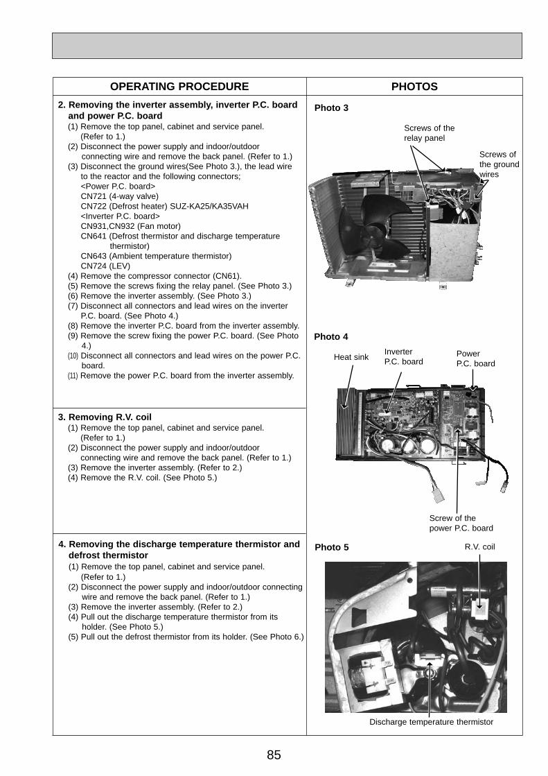
85
2. Removing the inverter assembly, inverter P.C. boardand power P.C. board (1) Remove the top panel, cabinet and service panel.
(Refer to 1.)(2) Disconnect the power supply and indoor/outdoor
connecting wire and remove the back panel. (Refer to 1.)(3) Disconnect the ground wires(See Photo 3.), the lead wire
to the reactor and the following connectors;<Power P.C. board>CN721 (4-way valve)CN722 (Defrost heater) SUZ-KA25/KA35VAH<Inverter P.C. board>CN931,CN932 (Fan motor)CN641 (Defrost thermistor and discharge temperature
thermistor)CN643 (Ambient temperature thermistor) CN724 (LEV)
(4) Remove the compressor connector (CN61).(5) Remove the screws fixing the relay panel. (See Photo 3.)(6) Remove the inverter assembly. (See Photo 3.)(7) Disconnect all connectors and lead wires on the inverter
P.C. board. (See Photo 4.)(8) Remove the inverter P.C. board from the inverter assembly.(9) Remove the screw fixing the power P.C. board. (See Photo
4.)(10) Disconnect all connectors and lead wires on the power P.C.
board.(11) Remove the power P.C. board from the inverter assembly.
4. Removing the discharge temperature thermistor anddefrost thermistor (1) Remove the top panel, cabinet and service panel.
(Refer to 1.)(2) Disconnect the power supply and indoor/outdoor connecting
wire and remove the back panel. (Refer to 1.)(3) Remove the inverter assembly. (Refer to 2.)(4) Pull out the discharge temperature thermistor from its
holder. (See Photo 5.)(5) Pull out the defrost thermistor from its holder. (See Photo 6.)
Photo 5
Discharge temperature thermistor
R.V. coil
OPERATING PROCEDURE PHOTOS
Photo 3
Photo 4
Screw of thepower P.C. board
Heat sink
3. Removing R.V. coil (1) Remove the top panel, cabinet and service panel.
(Refer to 1.)(2) Disconnect the power supply and indoor/outdoor
connecting wire and remove the back panel. (Refer to 1.)(3) Remove the inverter assembly. (Refer to 2.)(4) Remove the R.V. coil. (See Photo 5.)
InverterP.C. board
PowerP.C. board
Screws ofthe groundwires
Screws of therelay panel
OC322C--3qxp 07.3.12 3:44 PM Page 85

86
OPERATING PROCEDURE PHOTOS
Photo 6
Defrostthermistor
5. Removing outdoor fan motor(1) Remove the top panel, cabinet and service panel.
(Refer to 1.)(2) Disconnect the power supply and indoor/outdoor
connecting wire and remove the back panel. (Refer to 1.)(3) Disconnect the connectors for outdoor fan motor.(4) Remove the propeller nut. (5) Remove the propeller.(6) Remove the screws fixing the fan motor. (See Photo 7.)(7) Remove the fan motor.
Photo 8
Welded parts of 4-way valve
6. Removing the compressor and 4-way valve(1) Remove the top panel, cabinet and service panel.
(Refer to 1.)(2) Disconnect the power supply and indoor/outdoor
connecting wire and remove the back panel. (Refer to 1.)(3) Remove the inverter assembly. (Refer to 2.)(4) Recover gas from the refrigerant circuit.NOTE: Recover gas from the pipes until the pressure gauge
shows 0 kg/cm2 (0 MPa).
(5) Detach the welded part of the suction and the dischargepipe connected with compressor.
(6) Remove the nuts of compressor legs.(7) Remove the compressor.(8) Detach the welded part of pipes connected with 4-way
valve. (See Photo 8.)
Photo 7
Propeller
Screws of the outdoor fan motor
OC322C--3qxp 07.3.12 3:44 PM Page 86

87
SUZ-KA50VA.TH SUZ-KA60VA.TH SUZ-KA71VA.THSUZ-KA50VA 1.TH SUZ-KA60VA 1.TH SUZ-KA71VA 1.THOUTDOOR UNIT
OPERATING PROCEDURE PHOTOS
1. Removing the cabinet(1) Remove the screws of the service panel.(2) Remove the screws of the top panel.(3) Remove the screw of the valve cover.(4) Remove the service panel.(5) Remove the top panel.(6) Remove the valve cover.(7) Remove the screws of the cabinet.(8) Remove the cabinet.(9) Remove the screws of the back panel.(10) Remove the back panel.
Photo 2
Photo 1
Photo 3
Screw of the top panel
Screws of the cabinet
Screwsof thecabinet
Screwsof thetoppanel
Screw of the motor support
Set screws of the back panel
Screwsof thecabinet
Screw of the service panel
Screwof thevalvecover
Screwsof thebackpanel
OC322C--3qxp 07.3.12 3:44 PM Page 87

88
2. Removing the inverter assembly, inverter P.C. boardand power board (1) Remove the top panel, cabinet and service panel.
(Refer to 1.)(2) Remove the back panel.(Refer to 1.)(3) Disconnect the following connectors;
<Electronic control P.C. board>CN931 and CN932 (Fan motor)CN795 (LEV)CN661 (Discharge temperature thermistor, defrost
thermistor and outdoor heat exchanger temperature thermistor)
<Noise filter P.C. board>CN912 (4-way valve)
(4) Remove the compressor connector.(5) Remove the screws fixing the relay panel.(6) Remove the inverter assembly.(7) Disconnect all connectors and lead wires on the electronic
control P.C. board.(8) Remove the electronic control P.C. board from the inverter
assembly.(9) Remove the screws fixing the power board assembly.(10) Disconnect all connectors and lead wires on the power
board.(11) Remove the power board from the inverter assembly.(12) Disconnect all connectors and lead wires on the noise filter
P.C. board.(13) Remove the noise filter P.C. board from the inverter
assembly.
OPERATING PROCEDURE PHOTOS
Photo 4
3. Removing R.V. coil (1) Remove the top panel, cabinet and service panel.(2) Remove the back panel. (Refer to 1.)(3) Remove the inverter assembly. (Refer to 2.)(4) Remove the R.V. coil. (Photo 9)
Screws of the relay panel
Screws of the power board assembly
OC322C--3qxp 07.3.12 3:44 PM Page 88

89
5. Removing outdoor fan motor(1) Remove the top panel, cabinet and service panel.
(Refer to 1.)(2) Remove the back panel. (Refer to 1.)(3) Remove the inverter assembly. (Refer to 2.)(4) Remove the propeller.(5) Remove the screws fixing the fan motor.(6) Remove the fan motor.
Photo 7
PropellerScrews of the outdoor fan motor
OPERATING PROCEDURE PHOTOS
4. Removing the defrost thermistor, discharge temper-ature thermistor, outdoor heat exchanger tempera-ture thermistor and ambient temperature thermistor(1) Remove the top panel, cabinet and service panel.
(Refer to 1.)(2) Remove the back panel. (Refer to 1.)(3) Remove the inverter assembly. (Refer to 2.)(4) Pull out the defrost thermistor from its holder. (Photo 6)(5) Pull out the discharge temperature thermistor from its
holder. (Photo 5)(6) Pull out the outdoor heat exchanger temperature thermistor
from its holder. (Photo 6)(7) Pull out the ambient temperature thermistor from its holder.
(Photo 6)
Photo 5
Photo 6
Defrostthermistor
Discharge temperature thermistor
Outdoor heatexchangertemperaturethermistor
Ambienttemperaturethermistor
OC322C--3qxp 07.3.12 3:44 PM Page 89

90
6. Removing the compressor and 4-way valve(1) Remove the top panel, cabinet and service panel.
(Refer to 1.)(2) Remove the back panel. (Refer to 1.)(3) Remove the inverter assembly. (Refer to 2.)(4) Recover gas from the refrigerant circuit.NOTE: Recover gas from the pipes until the pressure
gauge shows 0 kg/cm2 (0 MPa).(5) Detach the welded part of the suction and the discharge
pipe connected with compressor. (Photo 9)(6) Remove the compressor nuts.(7) Remove the compressor.(8) Detach the welded part of 4-way valve and pipe. (Photo 8)
OPERATING PROCEDURE PHOTOS
Photo 8
Welded parts of 4-way valve
7. Removing the reactor(1) Remove the top panel. (Refer to 1.)(2) Disconnect the reactor lead wire.(3) Remove the screws of the reactor, and remove the reactor.
Photo 10
Screws of the reactor
Photo 9
Welded partof the dis-charge pipe
R.V. coil
Welded partof the suctionpipe
OC322C--3qxp 07.3.12 3:44 PM Page 90

91
14 PARTS LIST (non-RoHS compliant)
14-1. OUTDOOR UNIT ELECTRICAL PARTS
10
6
1 4
REACTORPOWER P.C. BOARDPOWER P.C. BOARDR.V. COILTHERMISTOR SETAMBIENT TEMPERATURE THERMISTORFUSE HOLDERFUSETERMINAL BLOCKTERMINAL BLOCKINVERTER P.C. BOARDINVERTER P.C. BOARDINVERTER P.C. BOARDINVERTER P.C. BOARDFUSEVARISTOR
E02 838 337E02 927 444E02 931 444E02 927 490E02 927 306E02 927 308E02 735 241E02 735 382E02 573 375E02 927 374E07 168 451E07 184 451E07 169 451E07 185 451E02 127 382E02 661 385
1
2
3456789
10
1112
Symbolin WiringDiagram
Q'ty/unit
DEFROST, DISCHARGE
250V/20A3P3PIncluding heat sink and RT64Including heat sink and RT64Including heat sink and RT64Including heat sink and RT64250V/3.15A
RemarksPart No.No. Part Name
L61
21S4RT61,RT62
RT65
F61TB1TB2
F71,F801NR62,NR63,NR64
11
11111111
11
1
11111111
1
11
11
1111111
1
11
1
11111111
111
SUZ-KA25VA
.TH
SUZ-KA25VAH
.TH
SUZ-KA35VA
.TH
SUZ-KA35VAH
.TH
SUZ-KA25VA.TH SUZ-KA35VA.THSUZ-KA25VAH.TH SUZ-KA35VAH.TH
2 3
7
8
9
Part numbers that are circled are not shown in the illustration.
5
OC322C--4qxp 07.3.12 3:45 PM Page 91

92
1
11
12
2
1820
13
10 9
SUZ-KA25VA.TH SUZ-KA35VA.THSUZ-KA25VAH.TH SUZ-KA35VAH.TH14-2. OUTDOOR UNIT STRUCTURAL PARTS AND FUNCTIONAL PARTS
3 4 5 6 7 8
19 17
23
21
2224
16 15 14
OC322C--4qxp 07.3.12 3:45 PM Page 92

93
E02 927 232E02 927 521E02 927 501E02 927 290E02 928 290E02 927 900E02 929 900E02 065 506E02 927 661E02 927 662E02 927 245E02 927 233E02 927 640E02 838 640E02 927 493E02 927 961E02 928 079E02 930 079E02 928 525 E02 930 525E02 928 523E02 930 523E02 838 523E02 929 523 E02 927 293E02 928 293E02 929 293E02 930 293E02 927 515E02 929 515E02 927 297E02 927 630E02 929 630E02 927 301E02 840 526E02 840 381E02 927 937E02 735 936
123
4
5
678910
11
1213
14
15
16
17
18
19
20
21
222324
25
KNB073FDVHKNB092FCAH3RUBBERS/SET9.526.35
RC0J50-
3.02.02403.01.8600
MCMC
LEV
MFH
26H
1111
1
311111
11
1
1
1
11
1
1
111
11
311111
111
1
1
1
1
11
1111
1111
131111
111
1
1
11
11
2
111
1
131111
111
1
1
1
1
11
1111
2
Symbol
in Wiring
Diagram
Q'ty/unit
RemarksPart No.No. Part Name SUZ- KA25VA
.TH
SUZ- KA35VA
.TH
SUZ-KA25VAH
.TH
SUZ-KA35VAH
.THCABINETGRILLEPROPELLER FANBASEBASECOMPRESSORCOMPRESSORCOMPRESSOR RUBBER SETSTOP VALVE (GAS)STOP VALVE (LIQUID)SERVICE PANELBACK PANELEXPANSION VALVEEXPANSION VALVEEXPANSION VALVE COIL4-WAY VALVETHERMO HOLDERTHERMO HOLDERCONDENSER WIRE NETCONDENSER WIRE NETCONDENSER NETCONDENSER NETCONDENSER NETCONDENSER NETSEPARATORSEPARATORSEPARATORSEPARATORMOTOR SUPPORTMOTOR SUPPORTTOP PANELOUTDOOR HEAT EXCHANGEROUTDOOR HEAT EXCHANGEROUTDOOR FAN MOTORDEFROST HEATERHEATER PROTECTORCAPILLARY TUBECAPILLARY TUBE
Part number that is circled is not shown in the illustration.
14-2. OUTDOOR UNIT STRUCTURAL PARTS AND FUNCTIONAL PARTS
SUZ-KA25VA.TH SUZ-KA35VA.THSUZ-KA25VAH.TH SUZ-KA35VAH.TH
OC322C--4qxp 07.3.12 3:45 PM Page 93

94
SUZ-KA50VA.TH SUZ-KA60VA.TH SUZ-KA71VA.TH14-3. OUTDOOR UNIT STRUCTURAL PARTS, ELECTRICAL PARTS AND
FUNCTIONAL PARTS
4
19
9
1
1310 12
2
5
6
7
8 16
14
20
22
23
24
25
293031
3
11
15
1718
21
28
27
26
OC322C--4qxp 07.3.12 3:45 PM Page 94

95
SUZ-KA50VA.TH SUZ-KA60VA.TH SUZ-KA71VA.TH14-3. OUTDOOR UNIT STRUCTURAL PARTS, ELECTRICAL PARTS AND
FUNCTIONAL PARTS
Symbolin WiringDiagram
Q'ty/unit
50 60 71
RemarksPart No.No. Part Name SUZ-KA•VA.TH
E02 819 297E02 851 630E02 853 630E02 938 301E02 851 501E02 851 290E02 853 290E02 819 232E02 819 009E02 819 521E02 853 646E02 065 506E02 853 506E02 939 900E02 853 900E02 851 661E02 819 661E02 821 662E02 822 662E02 851 640E02 853 640E02 851 493E02 853 299E02 935 490E02 891 961E02 819 650E02 819 245E07 170 450E07 171 450E07 223 450E02 935 374E02 823 375E02 851 337E02 935 444E02 935 309E02 851 308E02 935 440E02 819 233E02 817 009E02 851 515E02 127 382 E02 737 382E02 935 385E02 851 936E02 853 936E02 861 936
1
2
34
5
6789
10
11
12
13
14
151617181920
21
2223242526272829303132
33
34
35
TOP PANELOUTDOOR HEAT EXCHANGEROUTDOOR HEAT EXCHANGEROUTDOOR FAN MOTORPROPELLER FAN BASEBASECABINETHANDLEFAN GUARDHIGH PRESSURE SWITCHCOMPRESSOR RUBBER SETCOMPRESSOR RUBBER SETCOMPRESSOR COMPRESSORSTOP VALVE(GAS)STOP VALVE(GAS)STOP VALVE(LIQUID)STOP VALVE(LIQUID)EXPANSION VALVEEXPANSION VALVEEXPANSION VALVE COILOIL SEPARATORR.V. COIL4-WAY VALVEVALVE COVERSERVICE PANELOUTDOOR ELECTRONIC CONTROL P.C. BOARDOUTDOOR ELECTRONIC CONTROL P.C. BOARDOUTDOOR ELECTRONIC CONTROL P.C. BOARDTERMINAL BLOCKTERMINAL BLOCKREACTORNOISE FILTER P.C. BOARDAMBIENT TEMPERATURE THERMISTORTHERMISTOR SETPOWER BOARDBACK PANEL(OUT)HANDLEMOTOR SUPPORTFUSEFUSEFUSE & VARISTORCAPILLARY TUBE(TAPER PIPE)CAPILLARY TUBE(TAPER PIPE)CAPILLARY TUBE
RC0J60-
3RUBBERS/SET3RUBBERS/SETSNB130FLDH1TNB220FMCH12.715.886.359.52
3P3P
Including heat sink and RT64
250V/3.15A250V/1A250V/2A3.6x2.4x503.6x2.4x501.8x0.6x1000
MF
HPS
MCMC
LEV
21S4
TB1TB2
L
RT65RT61,RT62,RT68
F801F911
F64,NR64
11
111
111
3
1
11
1
1
1111
1
11111111111111
11
111
111
3
1
1
1
1
1
11111
11111111111111
DEFROST, DISCHARGEOUTDOOR HEAT EXCHANGER
1
111
11111
3
1
1
1
1111111
11111111111111
11
Part numbers that are circled are not shown in the illustration.
OC322C--4qxp 07.3.12 3:46 PM Page 95

96
SUZ-KA50VA.THSUZ-KA60VA.THSUZ-KA71VA.TH14-5. ACCESSORY
1 2
Symbolin WiringDiagram
Q'ty/unit
RemarksPart No.No. Part Name SUZ-KA50VA.TH
SUZ-KA60VA.TH
SUZ-KA71VA.TH
E02 817 704E02 444 705
12
DRAIN SOCKETDRAIN CAP [33
12
12
12
Outdoor unit 42 drain hole
Soft vinyl chloride hose of25mm inside diameter.
SUZ-KA25VA.TH SUZ-KA35VA.TH14-4. DRAIN SOCKET
Symbolin WiringDiagram
Q'ty/unit
SUZ-KA25VA.TH SUZ-KA35VA.TH RemarksParts No. Parts Name
E02 838 7041 DRAIN SOCKET
No.
1 1
1
OC322C--4qxp 07.3.12 3:46 PM Page 96
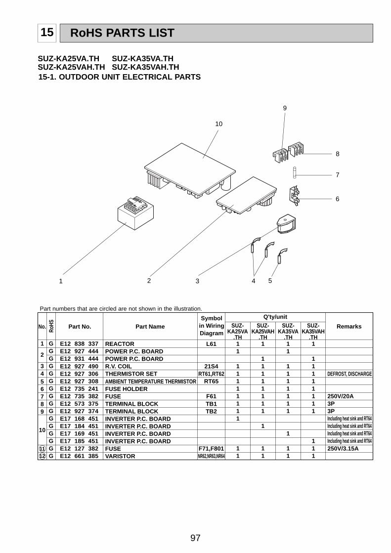
97
15 RoHS PARTS LIST
15-1. OUTDOOR UNIT ELECTRICAL PARTS
10
6
1 4
RoHS
REACTORPOWER P.C. BOARDPOWER P.C. BOARDR.V. COILTHERMISTOR SETAMBIENT TEMPERATURE THERMISTORFUSE HOLDERFUSETERMINAL BLOCKTERMINAL BLOCKINVERTER P.C. BOARDINVERTER P.C. BOARDINVERTER P.C. BOARDINVERTER P.C. BOARDFUSEVARISTOR
E12 838 337E12 927 444E12 931 444E12 927 490E12 927 306E12 927 308E12 735 241E12 735 382E12 573 375E12 927 374E17 168 451E17 184 451E17 169 451E17 185 451E12 127 382E12 661 385
1
2
3456789
10
1112
GGGGGGGGGGGGGGGG
Symbolin WiringDiagram
Q'ty/unit
DEFROST, DISCHARGE
250V/20A3P3PIncluding heat sink and RT64Including heat sink and RT64Including heat sink and RT64Including heat sink and RT64250V/3.15A
RemarksPart No.No. Part Name
L61
21S4RT61,RT62
RT65
F61TB1TB2
F71,F801NR62,NR63,NR64
11
11111111
11
1
11111111
1
11
11
1111111
1
11
1
11111111
111
SUZ-KA25VA
.TH
SUZ-KA25VAH
.TH
SUZ-KA35VA
.TH
SUZ-KA35VAH
.TH
SUZ-KA25VA.TH SUZ-KA35VA.THSUZ-KA25VAH.TH SUZ-KA35VAH.TH
2 3
7
8
9
Part numbers that are circled are not shown in the illustration.
5
OC322C--4qxp 07.3.12 3:46 PM Page 97

98
15-2. OUTDOOR UNIT STRUCTURAL PARTS AND FUNCTIONAL PARTS
1
11
12
2
1820
13
10 9
SUZ-KA25VA.TH SUZ-KA35VA.THSUZ-KA25VAH.TH SUZ-KA35VAH.TH
3 4 5 6 7 8
19 17
23
21
2224
16 15 14
OC322C--4qxp 07.3.12 3:46 PM Page 98

99
Ro
HS
E12 927 232E12 927 521E12 927 501E12 927 290E12 928 290E12 927 900E12 929 900E12 065 506E12 927 661E12 927 662E12 927 245E12 927 233E12 927 640E12 838 640E12 927 493E12 927 961E12 928 079E12 930 079E12 928 525 E12 930 525E12 928 523E12 930 523E12 838 523E12 929 523 E12 927 293E12 928 293E12 929 293E12 930 293E12 927 515E12 929 515E12 927 297E12 927 630E12 929 630E12 927 301E12 840 526E12 840 381E12 927 937E12 735 936
123
4
5
678910
11
1213
14
15
16
17
18
19
20
21
222324
25
GGGGGGGGGGGGGGGGGGGGGGGGGGGGGGGGGGGGGG
KNB073FDVHCKNB092FCAH3RUBBERS/SET9.526.35
RC0J50-
3.02.02403.01.8600
MCMC
LEV
MFH
26H
1111
1
311111
11
1
1
1
11
1
1
111
11
311111
111
1
1
1
1
11
1111
1111
131111
111
1
1
11
11
2
111
1
131111
111
1
1
1
1
11
1111
2
Symbol
in Wiring
Diagram
Q'ty/unit
RemarksPart No.No. Part Name SUZ- KA25VA
.TH
SUZ- KA35VA
.TH
SUZ-KA25VAH
.TH
SUZ-KA35VAH
.THCABINETGRILLEPROPELLER FANBASEBASECOMPRESSORCOMPRESSORCOMPRESSOR RUBBER SETSTOP VALVE (GAS)STOP VALVE (LIQUID)SERVICE PANELBACK PANELEXPANSION VALVEEXPANSION VALVEEXPANSION VALVE COIL4-WAY VALVETHERMO HOLDERTHERMO HOLDERCONDENSER WIRE NETCONDENSER WIRE NETCONDENSER NETCONDENSER NETCONDENSER NETCONDENSER NETSEPARATORSEPARATORSEPARATORSEPARATORMOTOR SUPPORTMOTOR SUPPORTTOP PANELOUTDOOR HEAT EXCHANGEROUTDOOR HEAT EXCHANGEROUTDOOR FAN MOTORDEFROST HEATERHEATER PROTECTORCAPILLARY TUBECAPILLARY TUBE
Part number that is circled is not shown in the illustration.
15-2. OUTDOOR UNIT STRUCTURAL PARTS AND FUNCTIONAL PARTS
SUZ-KA25VA.TH SUZ-KA35VA.THSUZ-KA25VAH.TH SUZ-KA35VAH.TH
OC322C--4qxp 07.3.12 3:46 PM Page 99

100
SUZ-KA50VA.TH SUZ-KA60VA.TH SUZ-KA71VA.THSUZ-KA50VA 1.TH SUZ-KA60VA 1.TH SUZ-KA71VA 1.TH15-3. OUTDOOR UNIT STRUCTURAL PARTS, ELECTRICAL PARTS AND
FUNCTIONAL PARTS
4
19
9
1
1310 12
2
5
6
7
8 16
14
20
22
23
24
25
293031
3
11
15
1718
21
28
27
26
OC322C--4qxp 07.3.12 3:46 PM Page 100

101
SUZ-KA50VA.TH SUZ-KA60VA.TH SUZ-KA71VA.THSUZ-KA50VA 1.TH SUZ-KA60VA 1.TH SUZ-KA71VA 1.TH15-3. OUTDOOR UNIT STRUCTURAL PARTS, ELECTRICAL PARTS AND
FUNCTIONAL PARTS
Ro
HS Symbol
in WiringDiagram
Q'ty/unit
50 60 71
RemarksPart No.No. Part Name SUZ-KA•VA.TH SUZ-KA•VA1.TH
E12 819 297E12 851 630E12 853 630E12 938 301E12 851 501E12 851 290E12 853 290E12 819 232E12 819 009E12 819 521E12 853 646E12 065 506E12 853 506E12 939 900E12 853 900E12 851 661E12 819 661E12 821 662E12 822 662E12 851 640E12 853 640E12 851 493E12 853 299E12 935 490E12 891 961E12 819 650E12 819 245E17 170 450E17 171 450E17 223 450E17 313 450E17 314 450E17 315 450E12 935 374E12 823 375E12 851 337E12 935 444E12 935 309E12 851 308E12 935 440E12 819 233E12 817 009E12 851 515E12 127 382 E12 737 382E12 935 385E12 851 936E12 853 936E12 861 936
1
2
34
5
6789
10
11
12
13
14
151617181920
21
2223242526272829303132
33
34
35
GGGGGGGGGGGGGGGGGGGGGGGGGGGGGGGGGGGGGGGGGGGGGGGGG
TOP PANELOUTDOOR HEAT EXCHANGEROUTDOOR HEAT EXCHANGEROUTDOOR FAN MOTORPROPELLER FAN BASEBASECABINETHANDLEFAN GUARDHIGH PRESSURE SWITCHCOMPRESSOR RUBBER SETCOMPRESSOR RUBBER SETCOMPRESSOR COMPRESSORSTOP VALVE(GAS)STOP VALVE(GAS)STOP VALVE(LIQUID)STOP VALVE(LIQUID)EXPANSION VALVEEXPANSION VALVEEXPANSION VALVE COILOIL SEPARATORR.V. COIL4-WAY VALVEVALVE COVERSERVICE PANELOUTDOOR ELECTRONIC CONTROL P.C. BOARDOUTDOOR ELECTRONIC CONTROL P.C. BOARDOUTDOOR ELECTRONIC CONTROL P.C. BOARDOUTDOOR ELECTRONIC CONTROL P.C. BOARDOUTDOOR ELECTRONIC CONTROL P.C. BOARDOUTDOOR ELECTRONIC CONTROL P.C. BOARDTERMINAL BLOCKTERMINAL BLOCKREACTORNOISE FILTER P.C. BOARDAMBIENT TEMPERATURE THERMISTORTHERMISTOR SETPOWER BOARDBACK PANEL(OUT)HANDLEMOTOR SUPPORTFUSEFUSEFUSE & VARISTORCAPILLARY TUBE(TAPER PIPE)CAPILLARY TUBE(TAPER PIPE)CAPILLARY TUBE
RC0J60-
3RUBBERS/SET3RUBBERS/SETSNB130FLDH1TNB220FMCHT12.715.886.359.52
3P3P
Including heat sink and RT64
250V/3.15A250V/1A250V/2A3.6x2.4x503.6x2.4x501.8x0.6x1000
MF
HPS
MCMC
LEV
21S4
TB1TB2
L
RT65RT61,RT62,RT68
F801F911
F64,NR64
11
111
111
3
1
11
1
1
1111
1
11111111111111
11
111
111
3
1
1
1
1
1
11111
11111111111111
DEFROST, DISCHARGEOUTDOOR HEAT EXCHANGER
1
111
11111
3
1
1
1
1111111
1
1111111111111
11
50 60 7111
111
111
3
1
11
1
1
1111
1
11111111111111
11
111
111
3
1
1
1
1
1
1111
1
11111111111111
1
111
11111
3
1
1
1
1111111
11111111111111
11
Part numbers that are circled are not shown in the illustration.
OC322C--4qxp 07.3.12 3:46 PM Page 101

HEAD OFFICE: TOKYO BLDG., 2-7-3, MARUNOUCHI, CHIYODA-KU, TOKYO100-8310, JAPAN
cCopyright 2005 MITSUBISHI ELECTRIC ENGINEERING CO.,LTDDistributed in Mar. 2007. No.OC322 REVISED EDITION-C PDF 7Distributed in Oct. 2006. No.OC322 REVISED EDITION-B PDF 7Distributed in Oct. 2005. No.OC322 REVISED EDITION-A PDF 8Distributed in Apr. 2005. No.OC322 PDF 8Made in Japan
New publication, effective Mar. 2007Specifications subject to change without notice
SUZ-KA50VA.TH SUZ-KA50VA 1.THSUZ-KA60VA.TH SUZ-KA60VA 1.THSUZ-KA71VA.TH SUZ-KA71VA 1.TH15-5. ACCESSORY
1 2
Symbolin WiringDiagram
Q'ty/unit
RemarksPart No.No. Part Name SUZ-KA50VA(1).TH
SUZ-KA60VA(1).TH
SUZ-KA71VA(1).TH
E12 817 704E12 444 705
12
GG
DRAIN SOCKETDRAIN CAP [33, 2PCS/SET
12
12
12
Ro
HS
Outdoor unit 42 drain hole
Soft vinyl chloride hose of25mm inside diameter.
SUZ-KA25VA.TH SUZ-KA35VA.THSUZ-KA25VAH.TH SUZ-KA35VAH.TH15-4. DRAIN SOCKET
Symbolin WiringDiagram
Q'ty/unit
SUZ-KA RemarksParts No. Parts Name25VA.TH 25VAH.TH 35VA.TH 35VAH.TH
E12 838 7041 G DRAIN SOCKET
No.
1 1
Ro
HS
1
OC322C--4qxp 07.3.12 3:46 PM Page 102
Top Related