


Languages
Pages
Legal

NI Serial Hardware Specifications Guide
This document lists safety and compliance information for NI Serial hardware, as well as physical specifications, software characteristics, and recommended operating conditions.
ContentsSafety and Electromagnetic Compatibility ............................................. 1PCI Serial Hardware ............................................................................... 5PCI Express Serial Hardware.................................................................. 14PXI Serial Hardware ............................................................................... 18USB Serial Hardware.............................................................................. 28ENET Serial Hardware ........................................................................... 32ExpressCard Serial Hardware ................................................................. 35PCMCIA Serial Hardware ...................................................................... 38Where to Go for Support......................................................................... 42
Safety and Electromagnetic CompatibilityThis section contains safety instructions and electromagnetic compatibility (EMC) information for the hardware it accompanies. Read this section before installing and using the new hardware.
Safety InformationThe following section contains important safety information that you must follow when installing and using the hardware.
Do not operate the hardware in a manner not specified in this document and in the user documentation. Misuse of the hardware can result in a hazard. You can compromise the safety protection if the hardware is damaged in any way. If the hardware is damaged, return it to National Instruments for repair.
NI Serial Hardware Specifications Guide 2 ni.com
Clean the hardware with a soft, nonmetallic brush. Make sure that the hardware is completely dry and free from contaminants before returning it to service.
Do not substitute parts or modify the hardware except as described in this document. Use the hardware only with the chassis, modules, accessories, and cables specified in the installation instructions or specifications. You must have all covers and filler panels installed during operation of the hardware.
Do not operate the hardware in an explosive atmosphere or where there may be flammable gases or fumes unless the hardware is UL (U.S.) or Ex (EU) Certified and marked for hazardous locations. The hardware must be in a suitably rated IP 54 minimum enclosure for hazardous locations. Refer to the hardware’s user documentation for more information.
You must insulate signal connections for the maximum voltage for which the hardware is rated. Do not exceed the maximum ratings for the hardware. Do not install wiring while the hardware is live with electrical signals. Do not remove or add connector blocks when power is connected to the system. Avoid contact between your body and the connector block signal when hot swapping hardware. Remove power from signal lines before connecting them to or disconnecting them from the hardware.
Operate the hardware only at or below Pollution Degree 2. Pollution is foreign matter in a solid, liquid, or gaseous state that can reduce dielectric strength or surface resistivity. The following is a description of pollution degrees:
• Pollution Degree 1 means no pollution or only dry, nonconductive pollution occurs. The pollution has no influence. Typical level for sealed components or coated PCBs.
• Pollution Degree 2 means that only nonconductive pollution occurs in most cases. Occasionally, however, a temporary conductivity caused by condensation must be expected. Typical level for most products.
• Pollution Degree 3 means that conductive pollution occurs, or dry, nonconductive pollution occurs that becomes conductive due to condensation.
© National Instruments Corporation 3 NI Serial Hardware Specifications Guide
Operate the hardware at or below the measurement category1 marked on the hardware label. Measurement circuits are subjected to working voltages2 and transient stresses (overvoltage) from the circuit to which they are connected during measurement or test. Measurement categories establish standard impulse withstand voltage levels that commonly occur in electrical distribution systems. The following is a description of measurement categories:
• Measurement Category I is for measurements performed on circuits not directly connected to the electrical distribution system referred to as MAINS3 voltage. This category is for measurements of voltages from specially protected secondary circuits. Such voltage measurements include signal levels, special hardware, limited-energy parts of hardware, circuits powered by regulated low-voltage sources, and electronics.
• Measurement Category II is for measurements performed on circuits directly connected to the electrical distribution system (MAINS3). This category refers to local-level electrical distribution, such as that provided by a standard wall outlet (for example, 115 AC voltage for U.S. or 230 AC voltage for Europe). Examples of Measurement Category II are measurements performed on household appliances, portable tools, and similar hardware.
• Measurement Category III is for measurements performed in the building installation at the distribution level. This category refers to measurements on hard-wired hardware such as hardware in fixed installations, distribution boards, and circuit breakers. Other examples are wiring, including cables, bus bars, junction boxes, switches, socket outlets in the fixed installation, and stationary motors with permanent connections to fixed installations.
• Measurement Category IV is for measurements performed at the primary electrical supply installation typically outside buildings. Examples include electricity meters and measurements on primary overcurrent protection devices and on ripple control units.
To obtain the safety certification(s) for this product, visit ni.com/certification, search by model number or product line, and click the appropriate link in the Certification column.
1 Measurement categories, also referred to as overvoltage or installation categories, are defined in electrical safety standard IEC 61010-1 and IEC 60664-1.
2 Working voltage is the highest rms value of an AC or DC voltage that can occur across any particular insulation.3 MAINS is defined as a hazardous live electrical supply system that powers hardware. Suitably rated measuring circuits may
be connected to the MAINS for measuring purposes.
NI Serial Hardware Specifications Guide 4 ni.com
Electromagnetic Compatibility InformationThis hardware has been tested and found to comply with the applicable regulatory requirements and limits for electromagnetic compatibility (EMC) as indicated in the hardware’s Declaration of Conformity (DoC)1. These requirements and limits are designed to provide reasonable protection against harmful interference when the hardware is operated in the intended electromagnetic environment. In special cases, for example when either highly sensitive or noisy hardware is being used in close proximity, additional mitigation measures may have to be employed to minimize the potential for electromagnetic interference.
While this hardware is compliant with the applicable regulatory EMC requirements, there is no guarantee that interference will not occur in a particular installation. To minimize the potential for the hardware to cause interference to radio and television reception or to experience unacceptable performance degradation, install and use this hardware in strict accordance with the instructions in the hardware documentation and the DoC1.
If this hardware does cause interference with licensed radio communications services or other nearby electronics, which can be determined by turning the hardware off and on, you are encouraged to try to correct the interference by one or more of the following measures:
• Reorient the antenna of the receiver (the device suffering interference).
• Relocate the transmitter (the device generating interference) with respect to the receiver.
• Plug the transmitter into a different outlet so that the transmitter and the receiver are on different branch circuits.
Some hardware may require the use of a metal, shielded enclosure (windowless version) to meet the EMC requirements for special EMC environments such as, for marine use or in heavy industrial areas. Refer to the hardware’s user documentation and the DoC1 for product installation requirements.
When the hardware is connected to a test object or to test leads, the system may become more sensitive to disturbances or may cause interference in the local electromagnetic environment.
Operation of this hardware in a residential area is likely to cause harmful interference. Users are required to correct the interference at their own expense or cease operation of the hardware.
Changes or modifications not expressly approved by National Instruments could void the user’s right to operate the hardware under the local regulatory rules.
1 The Declaration of Conformity (DoC) contains important EMC compliance information and instructions for the user or installer. To obtain the DoC for this product, visit ni.com/certification, search by model number or product line, and click the appropriate link in the Certification column.
© National Instruments Corporation 5 NI Serial Hardware Specifications Guide
PCI Serial HardwareThis section describes the characteristics of the PCI serial hardware and the recommended operating conditions.
Note This equipment is intended for indoor use only.
SafetyThis product meets the requirements of the following standards of safety for electrical equipment for measurement, control, and laboratory use:
• IEC 61010-1, EN 61010-1
• UL 61010-1, CSA 61010-1
Note For UL and other safety certifications, refer to the product label or the Online Product Certification section.
Electromagnetic CompatibilityThis product meets the requirements of the following EMC standards for electrical equipment for measurement, control, and laboratory use:
• EN 61326 (IEC 61326): Class A emissions; Basic immunity
• EN 55011 (CISPR 11): Group 1, Class A emissions
• AS/NZS CISPR 11: Group 1, Class A emissions
• FCC 47 CFR Part 15B: Class A emissions
• ICES-001: Class A emissions
Note For the standards applied to assess the EMC of this product, refer to the Online Product Certification section.
Note For EMC compliance, operate this device with shielded cabling.
CE ComplianceThis product meets the essential requirements of applicable European Directives as follows:
• 2006/95/EC; Low-Voltage Directive (safety)
• 2004/108/EC; Electromagnetic Compatibility Directive (EMC)
NI Serial Hardware Specifications Guide 6 ni.com
Online Product CertificationRefer to the product Declaration of Conformity (DoC) for additional regulatory compliance information. To obtain product certifications and the DoC for this product, visit ni.com/certification, search by model number or product line, and click the appropriate link in the Certification column.
Environmental ManagementNI is committed to designing and manufacturing products in an environmentally responsible manner. NI recognizes that eliminating certain hazardous substances from our products is beneficial to the environment and to NI customers.
For additional environmental information, refer to the NI and the Environment Web page at ni.com/environment. This page contains the environmental regulations and directives with which NI complies, as well as other environmental information not included in this document.
Waste Electrical and Electronic Equipment (WEEE)EU Customers At the end of the product life cycle, all products must be sent to a WEEE recycling center. For more information about WEEE recycling centers, National Instruments WEEE initiatives, and compliance with WEEE Directive 2002/96/EC on Waste and Electronic Equipment, visit ni.com/environment/weee.
PCI-843x Series HardwareNonisolated PCI Two-Port BoardsDimensions .............................................10.67 × 14.22 cm
(4.2 × 5.6 in.)
I/O connector ..........................................DB-9 male connector
Power requirement (from PCI channel)
PCI-8430/2
+5 VDC ....................................325 mA typical500 mA maximum
PCI-8431/2
+5 VDC ....................................500 mA typical700 mA maximum
RoHSNational Instruments (RoHS)
National Instruments RoHS ni.com/environment/rohs_china(For information about China RoHS compliance, go to ni.com/environment/rohs_china.)
© National Instruments Corporation 7 NI Serial Hardware Specifications Guide
Weight
PCI-8430/2...................................... 88 g
PCI-8431/2...................................... 92 g
Nonisolated PCI Four-Port BoardsDimensions............................................. 10.67 × 14.22 cm
(4.2 × 5.6 in.)
I/O connector1 ........................................ 10-position modular jack
Power requirement (from PCI channel)
PCI-8430/4
+5 VDC.................................... 400 mA typical600 mA maximum
PCI-8431/4
+5 VDC.................................... 725 mA typical1.1 A maximum
Weight
PCI-8430/4...................................... 99 g
PCI-8431/4...................................... 102 g
Nonisolated PCI Eight-Port BoardsDimensions............................................. 10.67 × 14.48 cm
(4.2 × 5.7 in.)
I/O connector2 ........................................ 68-position, SCSI type connector
Power requirement (from PCI channel)
PCI-8430/8
+5 VDC.................................... 600 mA typical900 mA maximum
PCI-8431/8
+5 VDC.................................... 1.3 A typical1.9 A maximum
Weight
PCI-8430/8...................................... 84 g
PCI-8431/8...................................... 85 g
1 The four-port PCI serial boards require cables, included in your kit, to convert the 10-position modular jacks to DB-9 male connectors.
2 The eight-port PCI serial boards require a cable, included in your kit, to convert the 68-position connector to eight DB-9 connectors.
NI Serial Hardware Specifications Guide 8 ni.com
Nonisolated PCI 16-Port BoardsDimensions .............................................10.67 × 17.52 cm
(4.2 × 6.9 in.)
I/O connector1.........................................68-position, VHDCI × 2
Power requirement (from PCI channel)
PCI-8430/16
+5 VDC ....................................935 mA typical1.4 A maximum
Weight ....................................................99 g
Isolated PCI Two-Port BoardsDimensions .............................................10.67 × 17.52 cm
(4.2 × 6.9 in.)
I/O connector ..........................................DB-9 male connector
Operating rated voltage (continuous)
RS-232.............................................–25 V to +25 V
RS-485.............................................–7 V to + 12 V
Isolation voltages
Port-to-port
Continuous ...............................60 VDC (CAT I)
Withstand .................................2000 Vrms, verified by a 5 s dielectric withstand test
Port-to-host
Continuous ...............................60 VDC (CAT I)
Withstand .................................2000 Vrms, verified by a 5 s dielectric withstand test
Power requirement (from PCI channel)
PCI-8432/2
+5 VDC ....................................380 mA typical570 mA maximum
PCI-8433/2
+5 VDC ....................................380 mA typical570 mA maximum
1 The 16-port PCI serial boards require two cables, included in your kit, to convert the two 68-position connectors to the 16 (2 × 8) DB-9 male connectors.
© National Instruments Corporation 9 NI Serial Hardware Specifications Guide
Weight
PCI-8432/2...................................... 102 g
PCI-8433/2...................................... 104 g
Isolated PCI Four-Port BoardsDimensions............................................. 10.67 × 17.44 cm
(4.2 × 6.9 in.)
I/O connector1 ........................................ 10-position modular jack
Operating rated voltage (continuous)
RS-232 ............................................ –25 V to +25 V
RS-485 ............................................ –7 V to + 12 V
Isolation voltages
Port-to-port
Continuous............................... 60 VDC (CAT I)
Withstand................................. 2000 Vrms, verified by a 5 s dielectric withstand test
Port-to-host
Continuous............................... 60 VDC (CAT I)
Withstand................................. 2000 Vrms, verified by a 5 s dielectric withstand test
Power requirement (from PCI channel)
PCI-8432/4
+5 VDC.................................... 550 mA typical815 mA maximum
PCI-8433/4
+5 VDC.................................... 785 mA typical1.2 A maximum
Weight
PCI-8432/4...................................... 105 g
PCI-8433/4...................................... 106 g
1 The four-port PCI serial boards require cables, included in your kit, to convert the 10-position modular jacks to DB-9 male connectors.
NI Serial Hardware Specifications Guide 10 ni.com
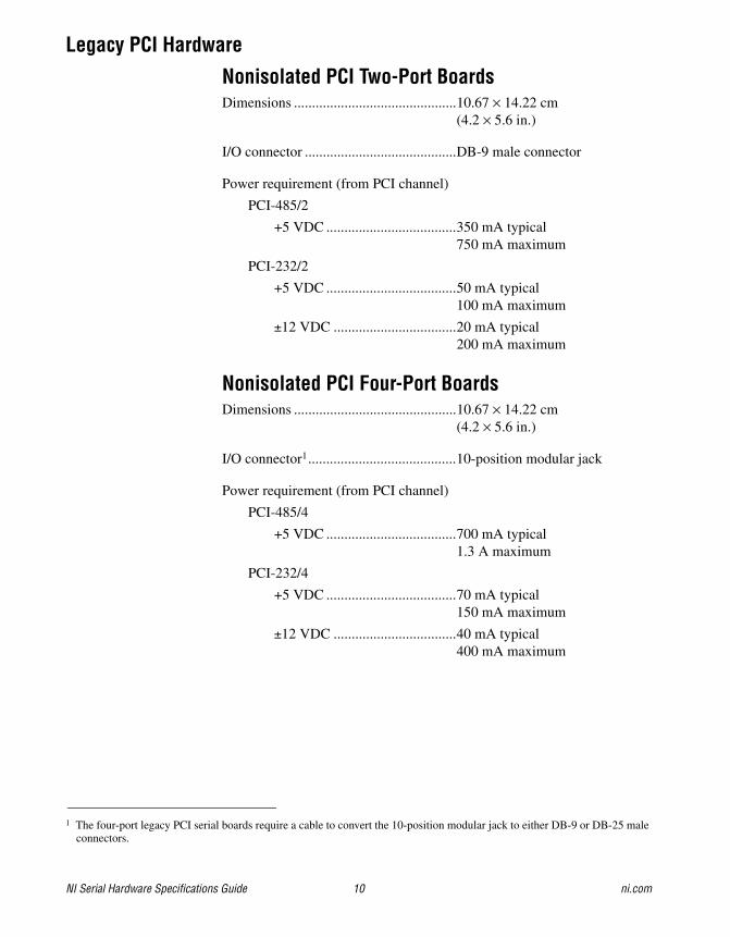
Legacy PCI Hardware
Nonisolated PCI Two-Port BoardsDimensions .............................................10.67 × 14.22 cm
(4.2 × 5.6 in.)
I/O connector ..........................................DB-9 male connector
Power requirement (from PCI channel)
PCI-485/2
+5 VDC ....................................350 mA typical750 mA maximum
PCI-232/2
+5 VDC ....................................50 mA typical100 mA maximum
±12 VDC ..................................20 mA typical200 mA maximum
Nonisolated PCI Four-Port BoardsDimensions .............................................10.67 × 14.22 cm
(4.2 × 5.6 in.)
I/O connector1.........................................10-position modular jack
Power requirement (from PCI channel)
PCI-485/4
+5 VDC ....................................700 mA typical1.3 A maximum
PCI-232/4
+5 VDC ....................................70 mA typical150 mA maximum
±12 VDC ..................................40 mA typical400 mA maximum
1 The four-port legacy PCI serial boards require a cable to convert the 10-position modular jack to either DB-9 or DB-25 male connectors.
© National Instruments Corporation 11 NI Serial Hardware Specifications Guide
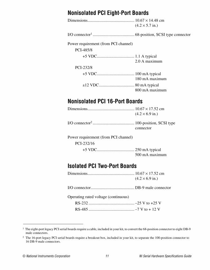
Nonisolated PCI Eight-Port BoardsDimensions............................................. 10.67 × 14.48 cm
(4.2 × 5.7 in.)
I/O connector1 ........................................ 68-position, SCSI type connector
Power requirement (from PCI channel)
PCI-485/8
+5 VDC.................................... 1.1 A typical2.0 A maximum
PCI-232/8
+5 VDC.................................... 100 mA typical180 mA maximum
±12 VDC.................................. 80 mA typical800 mA maximum
Nonisolated PCI 16-Port BoardsDimensions............................................. 10.67 × 17.52 cm
(4.2 × 6.9 in.)
I/O connector2 ........................................ 100-position, SCSI type connector
Power requirement (from PCI channel)
PCI-232/16
+5 VDC.................................... 250 mA typical500 mA maximum
Isolated PCI Two-Port BoardsDimensions............................................. 10.67 × 17.52 cm
(4.2 × 6.9 in.)
I/O connector.......................................... DB-9 male connector
Operating rated voltage (continuous)
RS-232 ............................................ –25 V to +25 V
RS-485 ............................................ –7 V to + 12 V
1 The eight-port legacy PCI serial boards require a cable, included in your kit, to convert the 68-position connector to eight DB-9 male connectors.
2 The 16-port legacy PCI serial boards require a breakout box, included in your kit, to separate the 100-position connector to 16 DB-9 male connectors.
NI Serial Hardware Specifications Guide 12 ni.com
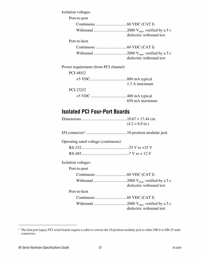
Isolation voltages
Port-to-port
Continuous ...............................60 VDC (CAT I)
Withstand .................................2000 Vrms, verified by a 5 s dielectric withstand test
Port-to-host
Continuous ...............................60 VDC (CAT I)
Withstand .................................2000 Vrms, verified by a 5 s dielectric withstand test
Power requirement (from PCI channel)
PCI-485/2
+5 VDC ....................................800 mA typical1.3 A maximum
PCI-232/2
+5 VDC ....................................400 mA typical650 mA maximum
Isolated PCI Four-Port BoardsDimensions .............................................10.67 × 17.44 cm
(4.2 × 6.9 in.)
I/O connector1.........................................10-position modular jack
Operating rated voltage (continuous)
RS-232.............................................–25 V to +25 V
RS-485.............................................–7 V to + 12 V
Isolation voltages
Port-to-port
Continuous ...............................60 VDC (CAT I)
Withstand .................................2000 Vrms, verified by a 5 s dielectric withstand test
Port-to-host
Continuous ...............................60 VDC (CAT I)
Withstand .................................2000 Vrms, verified by a 5 s dielectric withstand test
1 The four-port legacy PCI serial boards require a cable to convert the 10-position modular jack to either DB-9 or DB-25 male connectors.
© National Instruments Corporation 13 NI Serial Hardware Specifications Guide
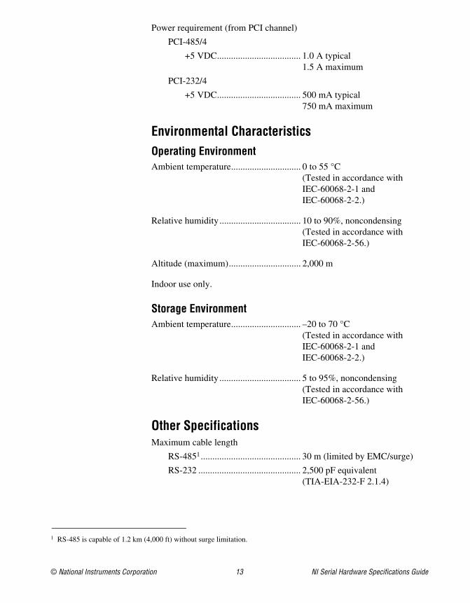
Power requirement (from PCI channel)
PCI-485/4
+5 VDC.................................... 1.0 A typical1.5 A maximum
PCI-232/4
+5 VDC.................................... 500 mA typical750 mA maximum
Environmental CharacteristicsOperating EnvironmentAmbient temperature.............................. 0 to 55 °C
(Tested in accordance with IEC-60068-2-1 and IEC-60068-2-2.)
Relative humidity ................................... 10 to 90%, noncondensing (Tested in accordance with IEC-60068-2-56.)
Altitude (maximum)............................... 2,000 m
Indoor use only.
Storage EnvironmentAmbient temperature.............................. –20 to 70 °C
(Tested in accordance with IEC-60068-2-1 and IEC-60068-2-2.)
Relative humidity ................................... 5 to 95%, noncondensing (Tested in accordance with IEC-60068-2-56.)
Other SpecificationsMaximum cable length
RS-4851........................................... 30 m (limited by EMC/surge)
RS-232 ............................................ 2,500 pF equivalent (TIA-EIA-232-F 2.1.4)
1 RS-485 is capable of 1.2 km (4,000 ft) without surge limitation.
NI Serial Hardware Specifications Guide 14 ni.com
Data line ESD protection (human body model)
RS-485.............................................±15 kV
RS-232.............................................±15 kV
PCI Express Serial HardwareThis section describes the characteristics of the PCI Express serial hardware and the recommended operating conditions.
Note This equipment is intended for indoor use only.
SafetyThis product meets the requirements of the following standards of safety for electrical equipment for measurement, control, and laboratory use:
• IEC 61010-1, EN 61010-1
• UL 61010-1, CSA 61010-1
Note For UL and other safety certifications, refer to the product label or the Online Product Certification section.
Electromagnetic CompatibilityThis product meets the requirements of the following EMC standards for electrical equipment for measurement, control, and laboratory use:
• EN 61326 (IEC 61326): Class A emissions; Basic immunity
• EN 55011 (CISPR 11): Group 1, Class A emissions
• AS/NZS CISPR 11: Group 1, Class A emissions
• FCC 47 CFR Part 15B: Class A emissions
• ICES-001: Class A emissions
Note For the standards applied to assess the EMC of this product, refer to the Online Product Certification section.
Note For EMC compliance, operate this device with shielded cabling.
CE ComplianceThis product meets the essential requirements of applicable European Directives as follows:
• 2006/95/EC; Low-Voltage Directive (safety)
• 2004/108/EC; Electromagnetic Compatibility Directive (EMC)
© National Instruments Corporation 15 NI Serial Hardware Specifications Guide
Online Product CertificationRefer to the product Declaration of Conformity (DoC) for additional regulatory compliance information. To obtain product certifications and the DoC for this product, visit ni.com/certification, search by model number or product line, and click the appropriate link in the Certification column.
Environmental ManagementNI is committed to designing and manufacturing products in an environmentally responsible manner. NI recognizes that eliminating certain hazardous substances from our products is beneficial to the environment and to NI customers.
For additional environmental information, refer to the NI and the Environment Web page at ni.com/environment. This page contains the environmental regulations and directives with which NI complies, as well as other environmental information not included in this document.
Waste Electrical and Electronic Equipment (WEEE)EU Customers At the end of the product life cycle, all products must be sent to a WEEE recycling center. For more information about WEEE recycling centers, National Instruments WEEE initiatives, and compliance with WEEE Directive 2002/96/EC on Waste and Electronic Equipment, visit ni.com/environment/weee.
NI PCIe-843x Series Hardware
Nonisolated PCI Express 16-Port BoardsDimensions (without bracket) ................ 11.12 × 17.53 cm (4.38 × 6.9 in.)
I/O connectors
NI PCIe-8430/16
RS-2321.................................... 68-position VHDCI × 2
PCI Express ............................. x1
1 The 16-port PCI Express serial boards require two cables, included in your kit, to convert the two 68-position connectors to the 16 (2 × 8) DB-9 male connectors.
RoHSNational Instruments (RoHS)
National Instruments RoHS ni.com/environment/rohs_china(For information about China RoHS compliance, go to ni.com/environment/rohs_china.)
NI Serial Hardware Specifications Guide 16 ni.com
NI PCIe-8431/16
RS-4851 ....................................68-position VHDCI × 2
PCI Express ..............................x1
Power requirement (from PCI Express channel)
NI PCIe-8430/16
+3.3 VDC .................................400 mA typical1.5 A maximum
+12 VDC ..................................210 mA typical250 mA maximum
NI PCIe-8431/16
+3.3 VDC2................................1.4 A typical, 3 A maximum
+12 VDC ..................................210 mA typical250 mA maximum
Weight
NI PCIe-8430/16 .............................99 g
NI PCIe-8431/16 .............................101 g
Nonisolated PCI Express 8-Port BoardsDimensions (without bracket) ................11.12 × 17.53 cm (4.38 × 6.9 in.)
I/O connectors
NI PCIe-8430/8
RS-2323 ....................................68-position VHDCI
PCI Express ..............................x1
NI PCIe-8431/8
RS-4853 ....................................68-position VHDCI
PCI Express ..............................x1
Power requirement (from PCI Express channel)
NI PCIe-8430/8
+3.3 VDC4................................200 mA typical750 mA maximum
+12 VDC ..................................190 mA typical220 mA maximum
1 The 16-port PCI Express serial boards require two cables, included in your kit, to convert the two 68-position connectors to the 16 (2 × 8) DB-9 male connectors.
2 These values are based on the assumption that all 16 ports (for the PCIe-8431/16) or 8 ports (for the PCIe-8431/8) are using a 620 Ω bias resistor and NI-offered terminators installed on both ends of the cable.
3 The 8-port PCI Express serial boards require a cable, included in your kit, to convert the 68-position connector to eight DB-9 male connectors.
4 These values are based on the assumption that all 16 ports (for the PCIe-8431/16) or 8 ports (for the PCIe-8431/8) are using a 620 Ω bias resistor and NI-offered terminators installed on both ends of the cable.
© National Instruments Corporation 17 NI Serial Hardware Specifications Guide
NI PCIe-8431/8
+3.3 VDC................................. 700 mA typical1.5 A maximum
+12 VDC.................................. 190 mA typical220 mA maximum
Weight
NI PCIe-8430/8............................... 88 g
NI PCIe-8431/8............................... 90 g
Environmental CharacteristicsOperating EnvironmentAmbient temperature.............................. 0 to 55 °C
(Tested in accordance with IEC-60068-2-1 and IEC-60068-2-2.)
Relative humidity ................................... 10 to 90%, noncondensing (Tested in accordance with IEC-60068-2-56.)
Altitude (maximum)............................... 2,000 m
Storage EnvironmentAmbient temperature.............................. –20 to 70 °C
(Tested in accordance with IEC-60068-2-1 and IEC-60068-2-2.)
Relative humidity ................................... 5 to 95%, noncondensing(Tested in accordance with IEC-60068-2-56.)
Other SpecificationsMaximum cable length
RS-4851........................................... 30 m (limited by EMC/surge)
RS-232 ............................................ 2,500 pF equivalent (TIA-EIA-232-F 2.1.4)
Data line ESD protection (human body model)
RS-485 ............................................ ±15 kV
RS-232 ............................................ ±15 kV
1 RS-485 is capable of 1.2 km (4,000 ft) without surge limitation.
NI Serial Hardware Specifications Guide 18 ni.com
PXI Serial HardwareThis section describes the characteristics of the PXI serial hardware and the recommended operating conditions.
Note This equipment is intended for indoor use only.
SafetyThis product meets the requirements of the following standards of safety for electrical equipment for measurement, control, and laboratory use:
• IEC 61010-1, EN 61010-1
• UL 61010-1, CSA 61010-1
Note For UL and other safety certifications, refer to the product label or the Online Product Certification section.
Electromagnetic CompatibilityThis product meets the requirements of the following EMC standards for electrical equipment for measurement, control, and laboratory use:
• EN 61326 (IEC 61326): Class A emissions; Basic immunity
• EN 55011 (CISPR 11): Group 1, Class A emissions
• AS/NZS CISPR 11: Group 1, Class A emissions
• FCC 47 CFR Part 15B: Class A emissions
• ICES-001: Class A emissions
Note For the standards applied to assess the EMC of this product, refer to the Online Product Certification section.
Note For EMC compliance, operate this device with shielded cabling.
CE ComplianceThis product meets the essential requirements of applicable European Directives as follows:
• 2006/95/EC; Low-Voltage Directive (safety)
• 2004/108/EC; Electromagnetic Compatibility Directive (EMC)
© National Instruments Corporation 19 NI Serial Hardware Specifications Guide
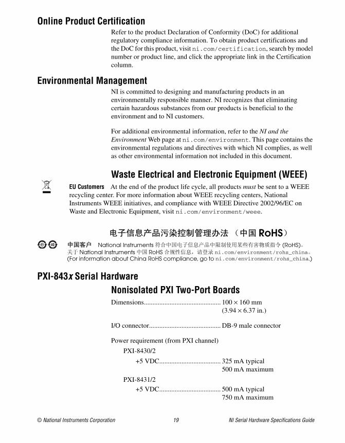
Online Product CertificationRefer to the product Declaration of Conformity (DoC) for additional regulatory compliance information. To obtain product certifications and the DoC for this product, visit ni.com/certification, search by model number or product line, and click the appropriate link in the Certification column.
Environmental ManagementNI is committed to designing and manufacturing products in an environmentally responsible manner. NI recognizes that eliminating certain hazardous substances from our products is beneficial to the environment and to NI customers.
For additional environmental information, refer to the NI and the Environment Web page at ni.com/environment. This page contains the environmental regulations and directives with which NI complies, as well as other environmental information not included in this document.
Waste Electrical and Electronic Equipment (WEEE)EU Customers At the end of the product life cycle, all products must be sent to a WEEE recycling center. For more information about WEEE recycling centers, National Instruments WEEE initiatives, and compliance with WEEE Directive 2002/96/EC on Waste and Electronic Equipment, visit ni.com/environment/weee.
PXI-843x Serial HardwareNonisolated PXI Two-Port BoardsDimensions............................................. 100 × 160 mm
(3.94 × 6.37 in.)
I/O connector.......................................... DB-9 male connector
Power requirement (from PXI channel)
PXI-8430/2
+5 VDC.................................... 325 mA typical500 mA maximum
PXI-8431/2
+5 VDC.................................... 500 mA typical750 mA maximum
RoHSNational Instruments (RoHS)
National Instruments RoHS ni.com/environment/rohs_china(For information about China RoHS compliance, go to ni.com/environment/rohs_china.)
NI Serial Hardware Specifications Guide 20 ni.com
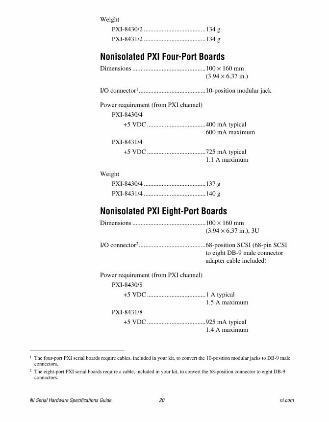
Weight
PXI-8430/2 ......................................134 g
PXI-8431/2 ......................................134 g
Nonisolated PXI Four-Port BoardsDimensions .............................................100 × 160 mm
(3.94 × 6.37 in.)
I/O connector1.........................................10-position modular jack
Power requirement (from PXI channel)
PXI-8430/4
+5 VDC ....................................400 mA typical600 mA maximum
PXI-8431/4
+5 VDC ....................................725 mA typical1.1 A maximum
Weight
PXI-8430/4 ......................................137 g
PXI-8431/4 ......................................140 g
Nonisolated PXI Eight-Port BoardsDimensions .............................................100 × 160 mm
(3.94 × 6.37 in.), 3U
I/O connector2.........................................68-position SCSI (68-pin SCSI to eight DB-9 male connector adapter cable included)
Power requirement (from PXI channel)
PXI-8430/8
+5 VDC ....................................1 A typical1.5 A maximum
PXI-8431/8
+5 VDC ....................................925 mA typical1.4 A maximum
1 The four-port PXI serial boards require cables, included in your kit, to convert the 10-position modular jacks to DB-9 male connectors.
2 The eight-port PXI serial boards require a cable, included in your kit, to convert the 68-position connector to eight DB-9 connectors.
© National Instruments Corporation 21 NI Serial Hardware Specifications Guide
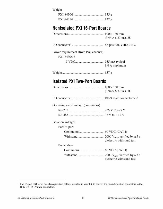
Weight
PXI-8430/8...................................... 135 g
PXI-8431/8...................................... 137 g
Nonisolated PXI 16-Port BoardsDimensions............................................. 100 × 160 mm
(3.94 × 6.37 in.), 3U
I/O connector1 ........................................ 68-position VHDCI × 2
Power requirement (from PXI channel)
PXI-8430/16
+5 VDC.................................... 935 mA typical1.4 A maximum
Weight .................................................... 157 g
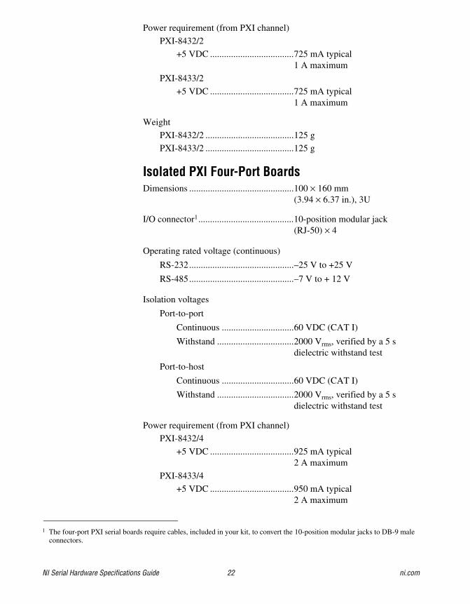
Isolated PXI Two-Port BoardsDimensions............................................. 100 × 160 mm
(3.94 × 6.37 in.), 3U
I/O connector.......................................... DB-9 male connector × 2
Operating rated voltage (continuous)
RS-232 ............................................ –25 V to +25 V
RS-485 ............................................ –7 V to + 12 V
Isolation voltages
Port-to-port
Continuous............................... 60 VDC (CAT I)
Withstand................................. 2000 Vrms, verified by a 5 s dielectric withstand test
Port-to-host
Continuous............................... 60 VDC (CAT I)
Withstand................................. 2000 Vrms, verified by a 5 s dielectric withstand test
1 The 16-port PXI serial boards require two cables, included in your kit, to convert the two 68-position connectors to the 16 (2 × 8) DB-9 male connectors.
NI Serial Hardware Specifications Guide 22 ni.com
Power requirement (from PXI channel)
PXI-8432/2
+5 VDC ....................................725 mA typical1 A maximum
PXI-8433/2
+5 VDC ....................................725 mA typical1 A maximum
Weight
PXI-8432/2 ......................................125 g
PXI-8433/2 ......................................125 g
Isolated PXI Four-Port BoardsDimensions .............................................100 × 160 mm
(3.94 × 6.37 in.), 3U
I/O connector1.........................................10-position modular jack (RJ-50) × 4
Operating rated voltage (continuous)
RS-232.............................................–25 V to +25 V
RS-485.............................................–7 V to + 12 V
Isolation voltages
Port-to-port
Continuous ...............................60 VDC (CAT I)
Withstand .................................2000 Vrms, verified by a 5 s dielectric withstand test
Port-to-host
Continuous ...............................60 VDC (CAT I)
Withstand .................................2000 Vrms, verified by a 5 s dielectric withstand test
Power requirement (from PXI channel)
PXI-8432/4
+5 VDC ....................................925 mA typical2 A maximum
PXI-8433/4
+5 VDC ....................................950 mA typical2 A maximum
1 The four-port PXI serial boards require cables, included in your kit, to convert the 10-position modular jacks to DB-9 male connectors.
© National Instruments Corporation 23 NI Serial Hardware Specifications Guide
Weight
PXI-8432/4...................................... 147 g
PXI-8433/4...................................... 147 g
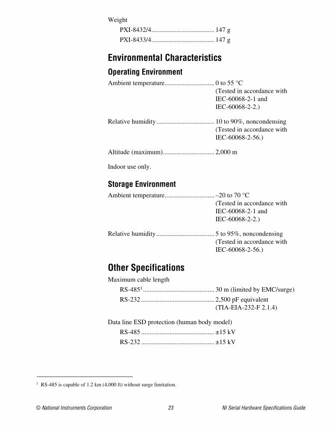
Environmental CharacteristicsOperating EnvironmentAmbient temperature.............................. 0 to 55 °C
(Tested in accordance with IEC-60068-2-1 and IEC-60068-2-2.)
Relative humidity ................................... 10 to 90%, noncondensing (Tested in accordance with IEC-60068-2-56.)
Altitude (maximum)............................... 2,000 m
Indoor use only.
Storage EnvironmentAmbient temperature.............................. –20 to 70 °C
(Tested in accordance with IEC-60068-2-1 and IEC-60068-2-2.)
Relative humidity ................................... 5 to 95%, noncondensing (Tested in accordance with IEC-60068-2-56.)
Other SpecificationsMaximum cable length
RS-4851........................................... 30 m (limited by EMC/surge)
RS-232 ............................................ 2,500 pF equivalent (TIA-EIA-232-F 2.1.4)
Data line ESD protection (human body model)
RS-485 ............................................ ±15 kV
RS-232 ............................................ ±15 kV
1 RS-485 is capable of 1.2 km (4,000 ft) without surge limitation.
NI Serial Hardware Specifications Guide 24 ni.com
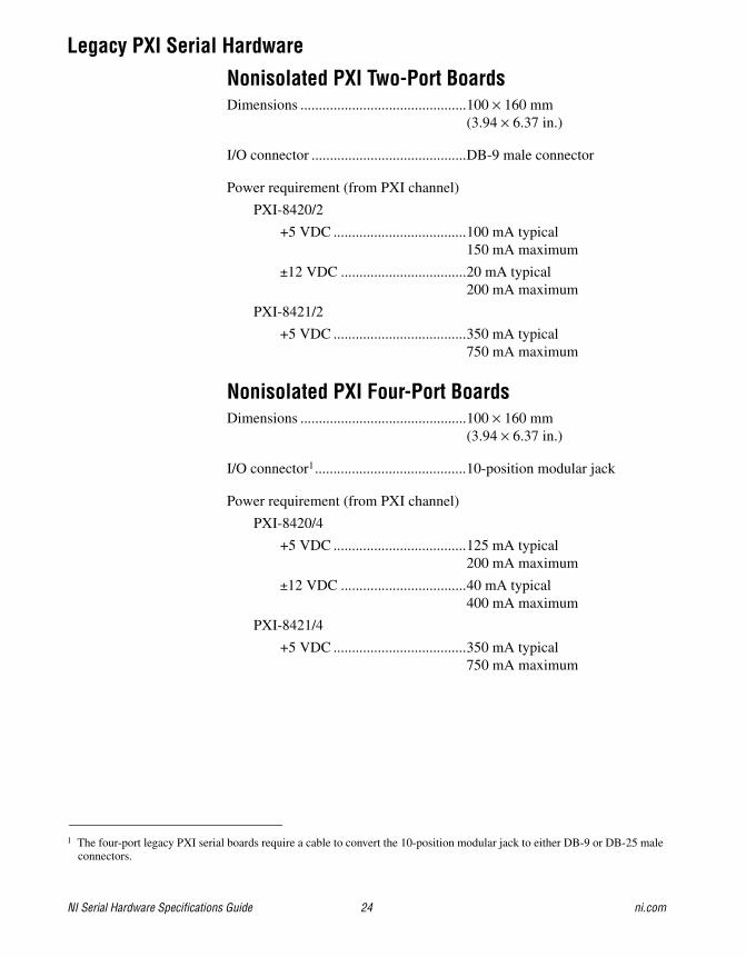
Legacy PXI Serial Hardware
Nonisolated PXI Two-Port BoardsDimensions .............................................100 × 160 mm
(3.94 × 6.37 in.)
I/O connector ..........................................DB-9 male connector
Power requirement (from PXI channel)
PXI-8420/2
+5 VDC ....................................100 mA typical150 mA maximum
±12 VDC ..................................20 mA typical200 mA maximum
PXI-8421/2
+5 VDC ....................................350 mA typical750 mA maximum
Nonisolated PXI Four-Port BoardsDimensions .............................................100 × 160 mm
(3.94 × 6.37 in.)
I/O connector1.........................................10-position modular jack
Power requirement (from PXI channel)
PXI-8420/4
+5 VDC ....................................125 mA typical200 mA maximum
±12 VDC ..................................40 mA typical400 mA maximum
PXI-8421/4
+5 VDC ....................................350 mA typical750 mA maximum
1 The four-port legacy PXI serial boards require a cable to convert the 10-position modular jack to either DB-9 or DB-25 male connectors.
© National Instruments Corporation 25 NI Serial Hardware Specifications Guide
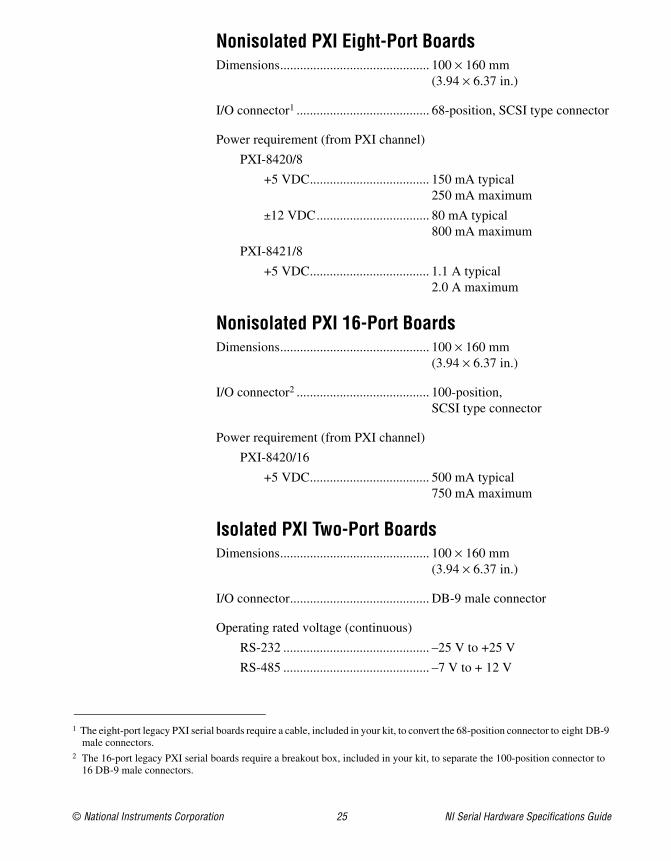
Nonisolated PXI Eight-Port BoardsDimensions............................................. 100 × 160 mm
(3.94 × 6.37 in.)
I/O connector1 ........................................ 68-position, SCSI type connector
Power requirement (from PXI channel)
PXI-8420/8
+5 VDC.................................... 150 mA typical250 mA maximum
±12 VDC.................................. 80 mA typical800 mA maximum
PXI-8421/8
+5 VDC.................................... 1.1 A typical2.0 A maximum
Nonisolated PXI 16-Port BoardsDimensions............................................. 100 × 160 mm
(3.94 × 6.37 in.)
I/O connector2 ........................................ 100-position, SCSI type connector
Power requirement (from PXI channel)
PXI-8420/16
+5 VDC.................................... 500 mA typical750 mA maximum
Isolated PXI Two-Port BoardsDimensions............................................. 100 × 160 mm
(3.94 × 6.37 in.)
I/O connector.......................................... DB-9 male connector
Operating rated voltage (continuous)
RS-232 ............................................ –25 V to +25 V
RS-485 ............................................ –7 V to + 12 V
1 The eight-port legacy PXI serial boards require a cable, included in your kit, to convert the 68-position connector to eight DB-9 male connectors.
2 The 16-port legacy PXI serial boards require a breakout box, included in your kit, to separate the 100-position connector to 16 DB-9 male connectors.
NI Serial Hardware Specifications Guide 26 ni.com
Isolation voltages
Port-to-port
Continuous ...............................60 VDC (CAT I)
Withstand .................................2000 Vrms, verified by a 5 s dielectric withstand test
Port-to-host
Continuous ...............................60 VDC (CAT I)
Withstand .................................2000 Vrms, verified by a 5 s dielectric withstand test
Power requirement (from PXI channel)
PXI-8422/2
+5 VDC ....................................400 mA typical650 mA maximum
PXI-8423/2
+5 VDC ....................................800 mA typical, 1.3 A maximum
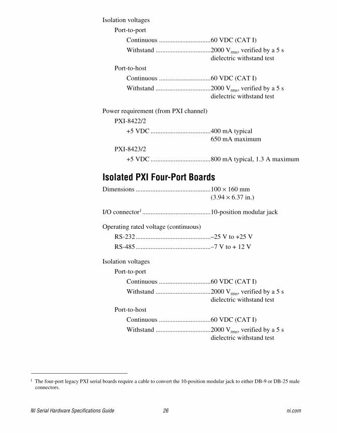
Isolated PXI Four-Port BoardsDimensions .............................................100 × 160 mm
(3.94 × 6.37 in.)
I/O connector1.........................................10-position modular jack
Operating rated voltage (continuous)
RS-232.............................................–25 V to +25 V
RS-485.............................................–7 V to + 12 V
Isolation voltages
Port-to-port
Continuous ...............................60 VDC (CAT I)
Withstand .................................2000 Vrms, verified by a 5 s dielectric withstand test
Port-to-host
Continuous ...............................60 VDC (CAT I)
Withstand .................................2000 Vrms, verified by a 5 s dielectric withstand test
1 The four-port legacy PXI serial boards require a cable to convert the 10-position modular jack to either DB-9 or DB-25 male connectors.

© National Instruments Corporation 27 NI Serial Hardware Specifications Guide
Power requirement (from PXI channel)
PXI-8422/4
+5 VDC.................................... 500 mA typical750 mA maximum
PXI-8423/4
+5 VDC.................................... 1.0 A typical1.5 A maximum
Environmental CharacteristicsOperating EnvironmentAmbient temperature.............................. 0 to 55 °C
(Tested in accordance with IEC-60068-2-1 and IEC-60068-2-2.)
Relative humidity ................................... 10 to 90%, noncondensing (Tested in accordance with IEC-60068-2-56.)
Altitude (maximum)............................... 2,000 m
Indoor use only.
Storage EnvironmentAmbient temperature.............................. –20 to 70 °C
(Tested in accordance with IEC-60068-2-1 and IEC-60068-2-2.)
Relative humidity ................................... 5 to 95%, noncondensing (Tested in accordance with IEC-60068-2-56.)
Other SpecificationsMaximum cable length
RS-4851........................................... 30 m (limited by EMC/surge)
RS-232 ............................................ 2,500 pF equivalent (TIA-EIA-232-F 2.1.4)
1 RS-485 is capable of 1.2 km (4,000 ft) without surge limitation.
NI Serial Hardware Specifications Guide 28 ni.com
Data line ESD protection (human body model)
RS-485.............................................±15 kV
RS-232.............................................±15 kV
USB Serial HardwareThis section describes the characteristics of the USB serial hardware and the recommended operating conditions.
Note This equipment is intended for indoor use only.
SafetyThis product meets the requirements of the following standards of safety for electrical equipment for measurement, control, and laboratory use:
• IEC 61010-1, EN 61010-1
• UL 61010-1, CSA 61010-1
Note For UL and other safety certifications, refer to the product label or the Online Product Certification section.
Electromagnetic CompatibilityThis product meets the requirements of the following EMC standards for electrical equipment for measurement, control, and laboratory use:
• EN 61326 (IEC 61326): Class A emissions; Basic immunity
• EN 55011 (CISPR 11): Group 1, Class A emissions
• AS/NZS CISPR 11: Group 1, Class A emissions
• FCC 47 CFR Part 15B: Class A emissions
• ICES-001: Class A emissions
Note For the standards applied to assess the EMC of this product, refer to the Online Product Certification section.
Note For EMC compliance, operate this device with shielded cabling.
CE ComplianceThis product meets the essential requirements of applicable European Directives as follows:
• 2006/95/EC; Low-Voltage Directive (safety)
• 2004/108/EC; Electromagnetic Compatibility Directive (EMC)
© National Instruments Corporation 29 NI Serial Hardware Specifications Guide
Online Product CertificationRefer to the product Declaration of Conformity (DoC) for additional regulatory compliance information. To obtain product certifications and the DoC for this product, visit ni.com/certification, search by model number or product line, and click the appropriate link in the Certification column.
Environmental ManagementNI is committed to designing and manufacturing products in an environmentally responsible manner. NI recognizes that eliminating certain hazardous substances from our products is beneficial to the environment and to NI customers.
For additional environmental information, refer to the NI and the Environment Web page at ni.com/environment. This page contains the environmental regulations and directives with which NI complies, as well as other environmental information not included in this document.
Waste Electrical and Electronic Equipment (WEEE)EU Customers At the end of the product life cycle, all products must be sent to a WEEE recycling center. For more information about WEEE recycling centers, National Instruments WEEE initiatives, and compliance with WEEE Directive 2002/96/EC on Waste and Electronic Equipment, visit ni.com/environment/weee.
One-Port USB HardwareDimensions............................................. 3.81 × 3.56 × 1.52 cm
(1.5 × 1.4 × 0.6 in.)
Case material.......................................... PVC
Weight
USB-232 ......................................... 121 g (0.27 lb)
USB-485 ......................................... 118 g (0.26 lb)
I/O connector.......................................... DB-9 male connector
USB connector ....................................... Captive cable with USB series A plug
RoHSNational Instruments (RoHS)
National Instruments RoHS ni.com/environment/rohs_china(For information about China RoHS compliance, go to ni.com/environment/rohs_china.)
NI Serial Hardware Specifications Guide 30 ni.com
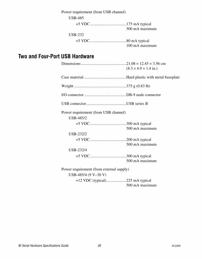
Power requirement (from USB channel)
USB-485
+5 VDC ....................................175 mA typical500 mA maximum
USB-232
+5 VDC ....................................80 mA typical100 mA maximum
Two and Four-Port USB HardwareDimensions .............................................21.08 × 12.45 × 3.56 cm
(8.3 × 4.9 × 1.4 in.)
Case material ..........................................Hard plastic with metal baseplate
Weight ....................................................375 g (0.83 lb)
I/O connector ..........................................DB-9 male connector
USB connector........................................USB series B
Power requirement (from USB channel)
USB-485/2
+5 VDC ....................................300 mA typical500 mA maximum
USB-232/2
+5 VDC ....................................200 mA typical500 mA maximum
USB-232/4
+5 VDC ....................................300 mA typical500 mA maximum
Power requirement (from external supply)
USB-485/4 (9 V–30 V)
+12 VDC (typical)....................225 mA typical500 mA maximum
© National Instruments Corporation 31 NI Serial Hardware Specifications Guide
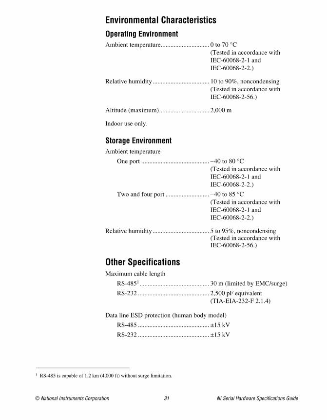
Environmental CharacteristicsOperating EnvironmentAmbient temperature.............................. 0 to 70 °C
(Tested in accordance with IEC-60068-2-1 and IEC-60068-2-2.)
Relative humidity ................................... 10 to 90%, noncondensing (Tested in accordance with IEC-60068-2-56.)
Altitude (maximum)............................... 2,000 m
Indoor use only.
Storage EnvironmentAmbient temperature
One port .......................................... –40 to 80 °C(Tested in accordance with IEC-60068-2-1 and IEC-60068-2-2.)
Two and four port ........................... –40 to 85 °C(Tested in accordance with IEC-60068-2-1 and IEC-60068-2-2.)
Relative humidity ................................... 5 to 95%, noncondensing (Tested in accordance with IEC-60068-2-56.)
Other SpecificationsMaximum cable length
RS-4851........................................... 30 m (limited by EMC/surge)
RS-232 ............................................ 2,500 pF equivalent (TIA-EIA-232-F 2.1.4)
Data line ESD protection (human body model)
RS-485 ............................................ ±15 kV
RS-232 ............................................ ±15 kV
1 RS-485 is capable of 1.2 km (4,000 ft) without surge limitation.
NI Serial Hardware Specifications Guide 32 ni.com
ENET Serial HardwareThis section describes the characteristics of the ENET serial hardware, along with the recommended operating conditions.
Note This equipment is intended for indoor use only.
SafetyThis product meets the requirements of the following standards of safety for electrical equipment for measurement, control, and laboratory use:
• IEC 60950-1, EN 60950-1
• UL 60950-1, CSA 60950-1
Note For UL and other safety certifications, refer to the product label or the Online Product Certification section.
Electromagnetic CompatibilityThis product meets the requirements of the following EMC standards for electrical equipment for measurement, control, and laboratory use:
• EN 61326 (IEC 61326): Class A emissions; Basic immunity
• EN 55011 (CISPR 11): Group 1, Class A emissions
• AS/NZS CISPR 11: Group 1, Class A emissions
• FCC 47 CFR Part 15B: Class A emissions
• ICES-001: Class A emissions
Note For the standards applied to assess the EMC of this product, refer to the Online Product Certification section.
Note For EMC compliance, operate this device with shielded cabling.
CE ComplianceThis product meets the essential requirements of applicable European Directives as follows:
• 2006/95/EC; Low-Voltage Directive (safety)
• 2004/108/EC; Electromagnetic Compatibility Directive (EMC)
© National Instruments Corporation 33 NI Serial Hardware Specifications Guide
Online Product CertificationRefer to the product Declaration of Conformity (DoC) for additional regulatory compliance information. To obtain product certifications and the DoC for this product, visit ni.com/certification, search by model number or product line, and click the appropriate link in the Certification column.
Environmental ManagementNI is committed to designing and manufacturing products in an environmentally responsible manner. NI recognizes that eliminating certain hazardous substances from our products is beneficial to the environment and to NI customers.
For additional environmental information, refer to the NI and the Environment Web page at ni.com/environment. This page contains the environmental regulations and directives with which NI complies, as well as other environmental information not included in this document.
Waste Electrical and Electronic Equipment (WEEE)EU Customers At the end of the product life cycle, all products must be sent to a WEEE recycling center. For more information about WEEE recycling centers, National Instruments WEEE initiatives, and compliance with WEEE Directive 2002/96/EC on Waste and Electronic Equipment, visit ni.com/environment/weee.
Electrical CharacteristicsPower requirement (from external supply)
External supply (9 V–30 V)
+12 VDC (typical) ................... 500 mA typical750 mA maximum
Environmental CharacteristicsOperating EnvironmentAmbient temperature.............................. 0 to 70 °C
(Tested in accordance with IEC-60068-2-1 and IEC-60068-2-2.)
RoHSNational Instruments (RoHS)
National Instruments RoHS ni.com/environment/rohs_china(For information about China RoHS compliance, go to ni.com/environment/rohs_china.)
NI Serial Hardware Specifications Guide 34 ni.com
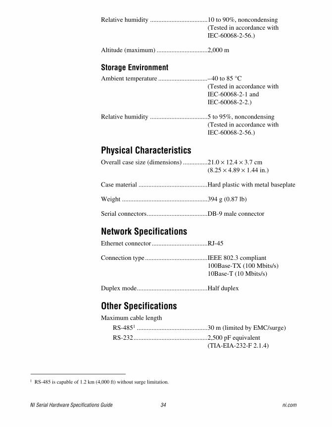
Relative humidity ...................................10 to 90%, noncondensing (Tested in accordance with IEC-60068-2-56.)
Altitude (maximum) ...............................2,000 m
Storage EnvironmentAmbient temperature ..............................–40 to 85 °C
(Tested in accordance with IEC-60068-2-1 and IEC-60068-2-2.)
Relative humidity ...................................5 to 95%, noncondensing (Tested in accordance with IEC-60068-2-56.)
Physical CharacteristicsOverall case size (dimensions) ...............21.0 × 12.4 × 3.7 cm
(8.25 × 4.89 × 1.44 in.)
Case material ..........................................Hard plastic with metal baseplate
Weight ....................................................394 g (0.87 lb)
Serial connectors.....................................DB-9 male connector
Network SpecificationsEthernet connector ..................................RJ-45
Connection type ......................................IEEE 802.3 compliant100Base-TX (100 Mbits/s)10Base-T (10 Mbits/s)
Duplex mode...........................................Half duplex
Other SpecificationsMaximum cable length
RS-4851 ...........................................30 m (limited by EMC/surge)
RS-232.............................................2,500 pF equivalent (TIA-EIA-232-F 2.1.4)
1 RS-485 is capable of 1.2 km (4,000 ft) without surge limitation.
© National Instruments Corporation 35 NI Serial Hardware Specifications Guide
Data line ESD protection (human body model)
RS-485 ............................................ ±15 kV
RS-232 ............................................ ±15 kV
ExpressCard Serial HardwareThis section describes the characteristics of the ExpressCard serial hardware, along with the recommended operating conditions.
Note This equipment is intended for indoor use only.
SafetyThis product meets the requirements of the following standards of safety for electrical equipment for measurement, control, and laboratory use:
• IEC 61010-1, EN 61010-1
• UL 61010-1, CSA 61010-1
Note For UL and other safety certifications, refer to the product label or the Online Product Certification section.
Electromagnetic CompatibilityThis product meets the requirements of the following EMC standards for electrical equipment for measurement, control, and laboratory use:
• EN 61326 (IEC 61326): Class A emissions; Basic immunity
• EN 55011 (CISPR 11): Group 1, Class A emissions
• AS/NZS CISPR 11: Group 1, Class A emissions
• FCC 47 CFR Part 15B: Class A emissions
• ICES-001: Class A emissions
Note For the standards applied to assess the EMC of this product, refer to the Online Product Certification section.
Note For EMC compliance, operate this device with shielded cabling.
CE ComplianceThis product meets the essential requirements of applicable European Directives as follows:
• 2006/95/EC; Low-Voltage Directive (safety)
• 2004/108/EC; Electromagnetic Compatibility Directive (EMC)
NI Serial Hardware Specifications Guide 36 ni.com
Online Product CertificationRefer to the product Declaration of Conformity (DoC) for additional regulatory compliance information. To obtain product certifications and the DoC for this product, visit ni.com/certification, search by model number or product line, and click the appropriate link in the Certification column.
Environmental ManagementNI is committed to designing and manufacturing products in an environmentally responsible manner. NI recognizes that eliminating certain hazardous substances from our products is beneficial to the environment and to NI customers.
For additional environmental information, refer to the NI and the Environment Web page at ni.com/environment. This page contains the environmental regulations and directives with which NI complies, as well as other environmental information not included in this document.
Waste Electrical and Electronic Equipment (WEEE)EU Customers At the end of the product life cycle, all products must be sent to a WEEE recycling center. For more information about WEEE recycling centers, National Instruments WEEE initiatives, and compliance with WEEE Directive 2002/96/EC on Waste and Electronic Equipment, visit ni.com/environment/weee.
Hardware SpecificationsDimensions .............................................34 × 75 × 5 mm
(1.34 × 2.95 × 0.2 in.)Weight
NI ExpressCard-8420/2 ...................16 g (0.5 oz)
NI ExpressCard-8421/2 ...................17 g (0.6 oz)
Connectors
I/O connector ...................................26-position latching connector with 20 cm breakout cable to two DB-9 male connectors
ExpressCard.....................................ExpressCard/34 standard connector interface
RoHSNational Instruments (RoHS)
National Instruments RoHS ni.com/environment/rohs_china(For information about China RoHS compliance, go to ni.com/environment/rohs_china.)
© National Instruments Corporation 37 NI Serial Hardware Specifications Guide
Power requirements(from ExpressCard USB interface)
Voltage............................................ +3.3 VDC ± 10%
NI ExpressCard-8420/2
+3.3 VDC................................. 100 mA typical250 mA maximum
NI ExpressCard-8421/2
+3.3 VDC................................. 160 mA typical260 mA maximum
Environmental CharacteristicsAltitude (maximum)............................... 2,000 m (at 25 °C ambient
temperature)
Pollution Degree .................................... 2
Indoor use only.
Operating EnvironmentAmbient temperature.............................. 0 to 65 °C
(Tested in accordance with IEC-60068-2-1 and IEC-60068-2-2.)
Relative humidity ................................... 5 to 95%, noncondensing (Tested in accordance with IEC-60068-2-56.)
Hot Surface Be careful when removing ExpressCards. Recently used ExpressCards may exceed safe handling temperatures.
Storage EnvironmentAmbient temperature.............................. –20 to 65 °C
(Tested in accordance with IEC-60068-2-1 and IEC-60068-2-2.)
Nonoperating thermal shock .................. –20 to 65 °C, 5 shocks
NI Serial Hardware Specifications Guide 38 ni.com
Other SpecificationsMaximum cable length
RS-4851 ...........................................30 m (limited by EMC/surge)
RS-232.............................................2,500 pF equivalent (TIA-EIA-232-F 2.1.4)
Data line ESD protection (human body model)
RS-485.............................................±15 kV
RS-232.............................................±15 kV
PCMCIA Serial HardwareThis section describes the characteristics of the PCMCIA serial hardware, along with the recommended operating conditions.
Note This equipment is intended for indoor use only.
SafetyThis product meets the requirements of the following standards of safety for electrical equipment for measurement, control, and laboratory use:
• IEC 60950-1, EN 60950-1
• UL 60950-1, CSA 60950-1
Note For UL and other safety certifications, refer to the product label or the Online Product Certification section.
Electromagnetic CompatibilityThis product meets the requirements of the following EMC standards for electrical equipment for measurement, control, and laboratory use:
• EN 61326 (IEC 61326): Class A emissions; Basic immunity
• EN 55011 (CISPR 11): Group 1, Class A emissions
• AS/NZS CISPR 11: Group 1, Class A emissions
• FCC 47 CFR Part 15B: Class A emissions
• ICES-001: Class A emissions
Note For the standards applied to assess the EMC of this product, refer to the Online Product Certification section.
Note For EMC compliance, operate this device with shielded cabling.
1 RS-485 is capable of 1.2 km (4,000 ft) without surge limitation.
© National Instruments Corporation 39 NI Serial Hardware Specifications Guide
CE ComplianceThis product meets the essential requirements of applicable European Directives as follows:
• 2006/95/EC; Low-Voltage Directive (safety)
• 2004/108/EC; Electromagnetic Compatibility Directive (EMC)
Online Product CertificationRefer to the product Declaration of Conformity (DoC) for additional regulatory compliance information. To obtain product certifications and the DoC for this product, visit ni.com/certification, search by model number or product line, and click the appropriate link in the Certification column.
Environmental ManagementNI is committed to designing and manufacturing products in an environmentally responsible manner. NI recognizes that eliminating certain hazardous substances from our products is beneficial to the environment and to NI customers.
For additional environmental information, refer to the NI and the Environment Web page at ni.com/environment. This page contains the environmental regulations and directives with which NI complies, as well as other environmental information not included in this document.
Waste Electrical and Electronic Equipment (WEEE)EU Customers At the end of the product life cycle, all products must be sent to a WEEE recycling center. For more information about WEEE recycling centers, National Instruments WEEE initiatives, and compliance with WEEE Directive 2002/96/EC on Waste and Electronic Equipment, visit ni.com/environment/weee.
Hardware SpecificationsDimensions............................................. Type II PC card
I/O connector.......................................... Adapter cable with DB-9 male Dsub connector and converter for PC card
RoHSNational Instruments (RoHS)
National Instruments RoHS ni.com/environment/rohs_china(For information about China RoHS compliance, go to ni.com/environment/rohs_china.)
NI Serial Hardware Specifications Guide 40 ni.com
Power requirement (from PCMCIA expansion slot)
PCMCIA-232
+5 VDC ....................................40 mA typical150 mA maximum
PCMCIA-485
+5 VDC ....................................110 mA typical225 mA maximum
PCMCIA-232/2
+5 VDC ....................................60 mA typical250 mA maximum
PCMCIA-485/2
+5 VDC ....................................150 mA typical400 mA maximum
PCMCIA-232/4
+5 VDC ....................................60 mA typical200 mA maximum
Environmental CharacteristicsOperating EnvironmentAmbient temperature ..............................0 to 55 °C
(Tested in accordance with IEC-60068-2-1 and IEC-60068-2-2.)
Relative humidity ...................................10 to 90%, noncondensing (Tested in accordance with IEC-60068-2-56.)
Altitude (maximum) ...............................2,000 m
Storage EnvironmentAmbient temperature ..............................–40 to 120 °C
(Tested in accordance with IEC-60068-2-1 and IEC-60068-2-2.)
Relative humidity ...................................5 to 95%, noncondensing (Tested in accordance with IEC-60068-2-56.)
© National Instruments Corporation 41 NI Serial Hardware Specifications Guide
Other SpecificationsMaximum cable length
RS-4851........................................... 30 m (limited by EMC/surge)
RS-232 ............................................ 2,500 pF equivalent (TIA-EIA-232-F 2.1.4)
Data line ESD protection (human body model)
RS-485 ............................................ ±15 kV
RS-232 ............................................ ±15 kV
1 RS-485 is capable of 1.2 km (4,000 ft) without surge limitation.
National Instruments, NI, ni.com, and LabVIEW are trademarks of National Instruments Corporation. Refer to the Terms of Use section on ni.com/legal for more information about National Instruments trademarks. Other product and company names mentioned herein are trademarks or trade names of their respective companies. For patents covering National Instruments products/technology, refer to the appropriate location: Help»Patents in your software, the patents.txt file on your media, or the National Instruments Patent Notice at ni.com/patents.
© 2004–2009 National Instruments Corporation. All rights reserved. 371332G-01 Dec09
Where to Go for SupportThe National Instruments Web site is your complete resource for technical support. At ni.com/support you have access to everything from troubleshooting and application development self-help resources to email and phone assistance from NI Application Engineers.
A Declaration of Conformity (DoC) is our claim of compliance with the Council of the European Communities using the manufacturer’s declaration of conformity. This system affords the user protection for electromagnetic compatibility (EMC) and product safety. You can obtain the DoC for your product by visiting ni.com/certification. If your product supports calibration, you can obtain the calibration certificate for your product at ni.com/calibration.
National Instruments corporate headquarters is located at 11500 North Mopac Expressway, Austin, Texas, 78759-3504. National Instruments also has offices located around the world to help address your support needs. For telephone support in the United States, create your service request at ni.com/support and follow the calling instructions or dial 512 795 8248. For telephone support outside the United States, contact your local branch office:
Australia 1800 300 800, Austria 43 662 457990-0, Belgium 32 (0) 2 757 0020, Brazil 55 11 3262 3599, Canada 800 433 3488, China 86 21 5050 9800, Czech Republic 420 224 235 774, Denmark 45 45 76 26 00, Finland 358 (0) 9 725 72511, France 01 57 66 24 24, Germany 49 89 7413130, India 91 80 41190000, Israel 972 3 6393737, Italy 39 02 41309277, Japan 0120-527196, Korea 82 02 3451 3400, Lebanon 961 (0) 1 33 28 28, Malaysia 1800 887710, Mexico 01 800 010 0793, Netherlands 31 (0) 348 433 466, New Zealand 0800 553 322, Norway 47 (0) 66 90 76 60, Poland 48 22 328 90 10, Portugal 351 210 311 210, Russia 7 495 783 6851, Singapore 1800 226 5886, Slovenia 386 3 425 42 00, South Africa 27 0 11 805 8197, Spain 34 91 640 0085, Sweden 46 (0) 8 587 895 00, Switzerland 41 56 2005151, Taiwan 886 02 2377 2222, Thailand 662 278 6777, Turkey 90 212 279 3031, United Kingdom 44 (0) 1635 523545
Top Related