


Languages
Pages
Legal

Networks: Token Ring and FDDI
1
Token Ringand
Fiber Distributed Data Interface (FDDI)
Networks: Token Ring and FDDI
2
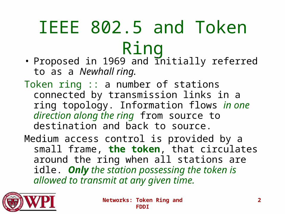
IEEE 802.5 and Token Ring• Proposed in 1969 and initially referred to as a
Newhall ring.Token ring :: a number of stations connected by
transmission links in a ring topology. Information flows in one direction along the ring from source to destination and back to source.
Medium access control is provided by a small frame, the token, that circulates around the ring when all stations are idle. Only the station possessing the token is allowed to transmit at any given time.
Networks: Token Ring and FDDI
3
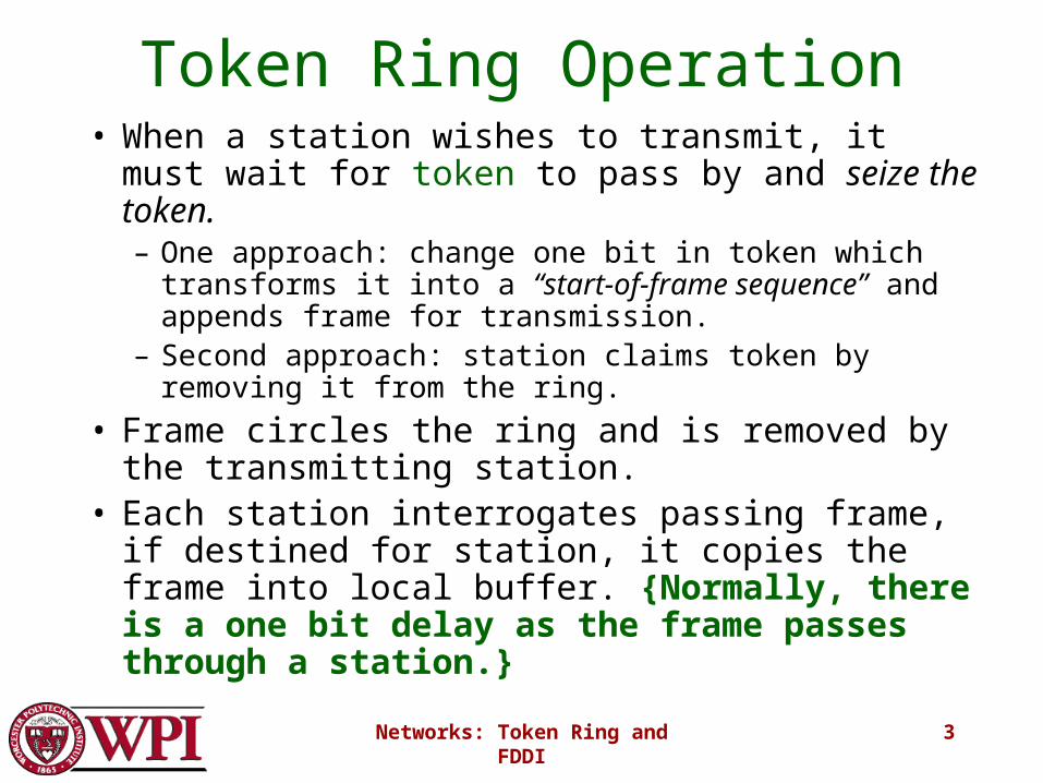
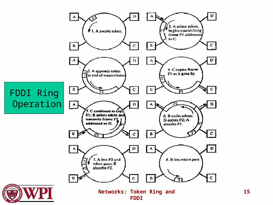
Token Ring Operation• When a station wishes to transmit, it must wait for
token to pass by and seize the token.– One approach: change one bit in token which transforms
it into a “start-of-frame sequence” and appends frame for transmission.
– Second approach: station claims token by removing it from the ring.
• Frame circles the ring and is removed by the transmitting station.
• Each station interrogates passing frame, if destined for station, it copies the frame into local buffer. {Normally, there is a one bit delay as the frame passes through a station.}

Networks: Token Ring and FDDI
4
Wiring center
A
B
CD
E
Figure 6.58Leon-Garcia & Widjaja: Communication NetworksCopyright ©2000 The McGraw Hill Companies
Token Ring Networkwith star topology
Networks: Token Ring and FDDI
5
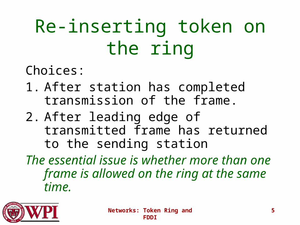
Re-inserting token on the ring
Choices:1. After station has completed transmission
of the frame.2. After leading edge of transmitted frame
has returned to the sending stationThe essential issue is whether more than one
frame is allowed on the ring at the same time.
Networks: Token Ring and FDDI
6
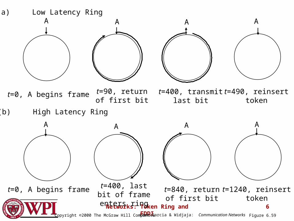
A A A
A A A A
t=0, A begins frame t=90, returnof first bit
t=400, transmitlast bit
A
t=490, reinserttoken
t=0, A begins frame t=400, last bit of frame enters ring
t=840, return of first bit
t=1240, reinserttoken
(a) Low Latency Ring
(b) High Latency Ring
Figure 6.59Leon-Garcia & Widjaja: Communication NetworksCopyright ©2000 The McGraw Hill Companies
Networks: Token Ring and FDDI
7
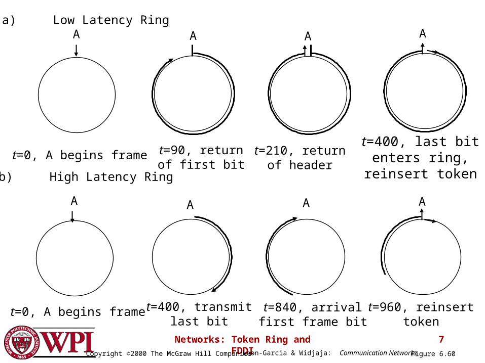
A A A
A A A A
t=0, A begins frame t=90, returnof first bit
t=210, return of header
A
t=400, last bit enters ring, reinsert token
t=0, A begins frame t=400, transmitlast bit
t=840, arrivalfirst frame bit
t=960, reinserttoken
(b) High Latency Ring
(a) Low Latency Ring
Figure 6.60Leon-Garcia & Widjaja: Communication NetworksCopyright ©2000 The McGraw Hill Companies
Networks: Token Ring and FDDI
8
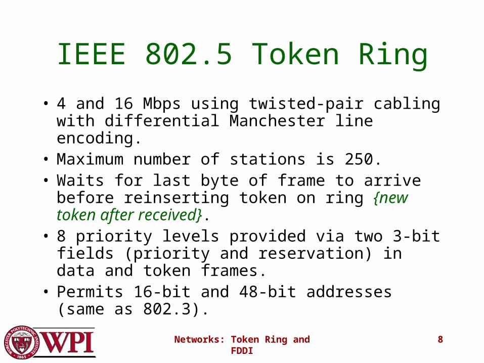
IEEE 802.5 Token Ring
• 4 and 16 Mbps using twisted-pair cabling with differential Manchester line encoding.
• Maximum number of stations is 250.• Waits for last byte of frame to arrive before
reinserting token on ring {new token after received}.
• 8 priority levels provided via two 3-bit fields (priority and reservation) in data and token frames.
• Permits 16-bit and 48-bit addresses (same as 802.3).
Networks: Token Ring and FDDI
9
Token Ring
• Under light load – delay is added due to waiting for the token.
• Under heavy load – ring is “round-robin”• The ring must be long enough to hold the
complete token.• Advantages – fair access • Disadvantages – ring is single point of failure,
added issues due to token maintenance.
Networks: Token Ring and FDDI
10
Token Maintenance Issues
What can go wrong?
• Loss of token (no token circulating)
• Duplication of token (forgeries or mistakes)The need to designate one station as the
active ring monitor.
• Persistently circulating frame
• Deal with active monitor going down.
Networks: Token Ring and FDDI
11
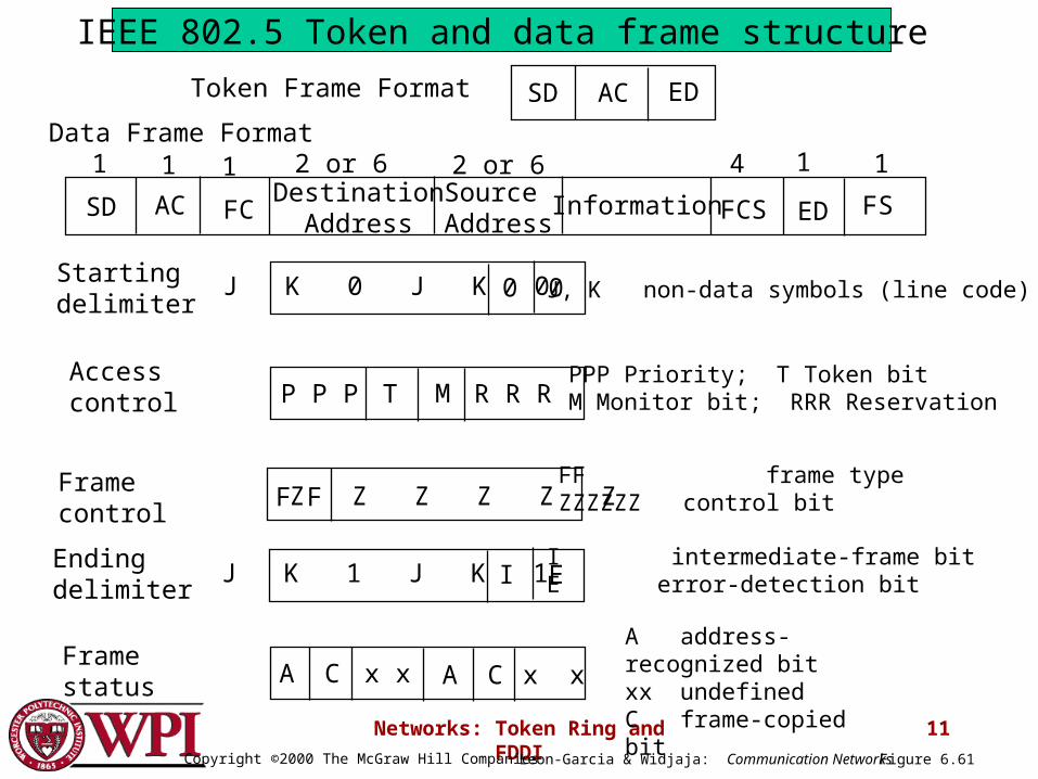
SDDestination
AddressSource Address
Information FCS
1 4
EDFC
2 or 6 2 or 61 1
AC
1
FS
1
SD AC EDToken Frame Format
P P P T M R R RAccess control
PPP Priority; T Token bitM Monitor bit; RRR Reservation
Frame control
FF frame typeZZZZZZ control bitF F Z Z Z Z Z Z
Ending delimiter
I intermediate-frame bitE error-detection bit
Framestatus
A address-recognized bitxx undefinedC frame-copied bit
I EJ K 1 J K 1
A C x x A C x x
Data Frame Format
Starting delimiter
J, K non-data symbols (line code)0 0J K 0 J K 0
Figure 6.61Leon-Garcia & Widjaja: Communication NetworksCopyright ©2000 The McGraw Hill Companies
IEEE 802.5 Token and data frame structure
Networks: Token Ring and FDDI
12
Fiber Distributed Data Interface (FDDI)
• FDDI uses a ring topology of multimode or single mode optical fiber transmission links operating at 100 Mbps to span up to 200 kms and permits up to 500 stations.
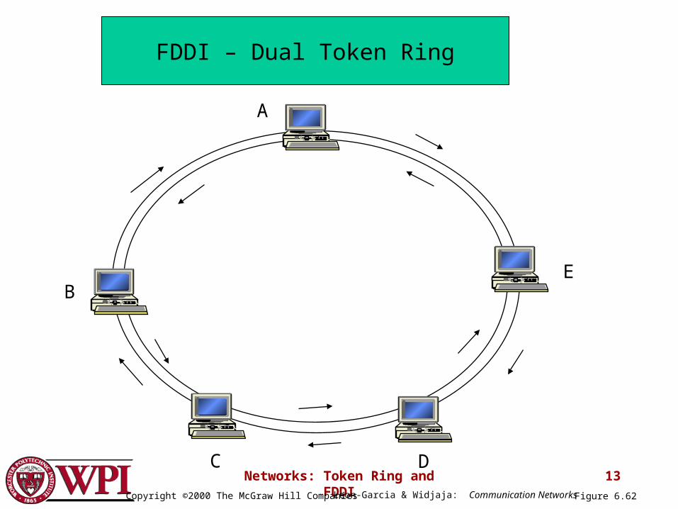
• Employs dual counter-rotating rings.• 16 and 48-bit addresses are allowed.• In FDDI, token is absorbed by station and released
as soon as it completes the frame transmission {release after transmission}.
Networks: Token Ring and FDDI
13
A
E
DC
B
Figure 6.62Leon-Garcia & Widjaja: Communication NetworksCopyright ©2000 The McGraw Hill Companies
FDDI – Dual Token Ring
Networks: Token Ring and FDDI
14
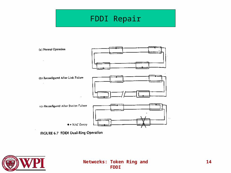
FDDI Repair
Networks: Token Ring and FDDI
15
FDDI Ring Operation
Networks: Token Ring and FDDI
16
FDDI
• To accommodate a mixture of stream and bursty traffic, FDDI is designed to handle two types of traffic:– Synchronous frames that typically have tighter delay
requirements (e.g., voice and video)– Asynchronous frames have greater delay tolerances
(e.g., data traffic)
• FDDI uses TTRT (Target Token Rotation Time) to ensure that token rotation time is less than some value.
Networks: Token Ring and FDDI
17
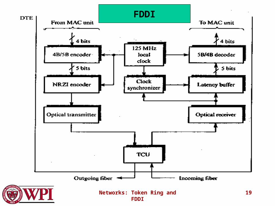
FDDI Data Encoding
• Cannot use differential Manchester because 100 Mbps FDDI would require 200 Mbaud!
• Instead each ring interface has its own local clock.– Outgoing data is transmitted using this clock.– Incoming data is received using a clock that is
frequency and phase locked to the transitions in the incoming bit stream.
Networks: Token Ring and FDDI
18
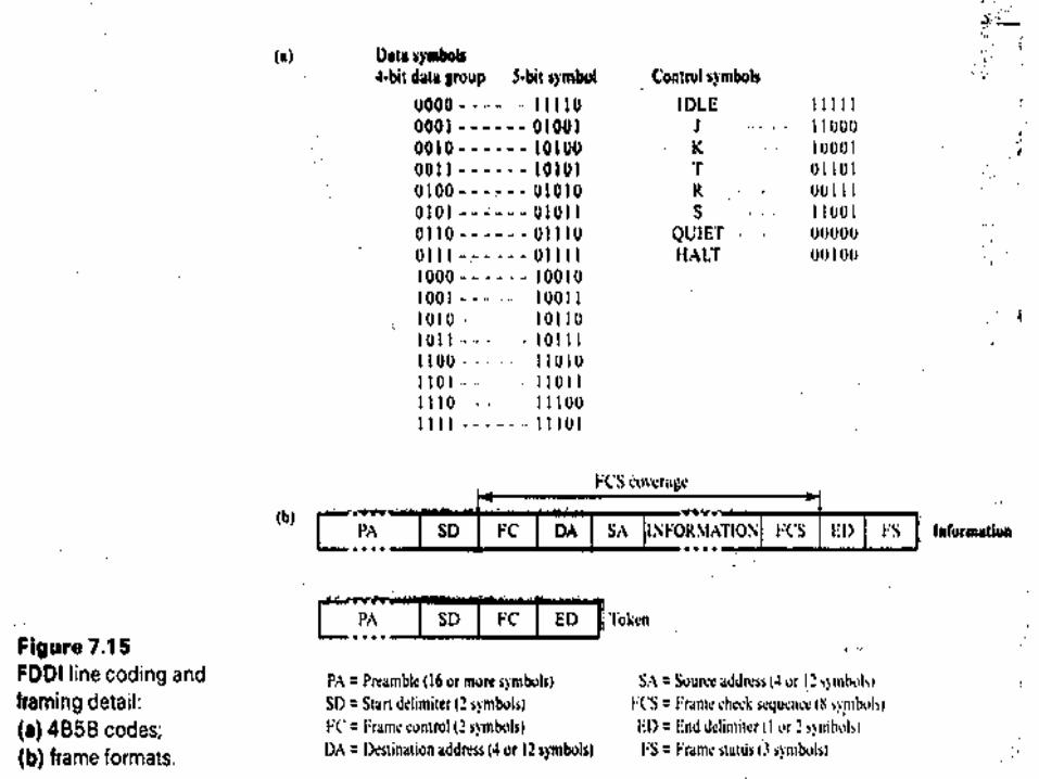
FDDI Data Encoding• Data is encoded using a 4B/5B encoder.
– For each four bits of data transmitted, a corresponding 5-bit codeword is generated by the encoder.
– There is a maximum of two consecutive zero bits in each symbol.
• The symbols are then shifted out through a NRZI encoder which produces a signal transition whenever a 1 bit is being transmitted and no transition when a 0 bit is transmitted guarantees a signal transition at least every two bits.
• Local clock is 125MHz. This yields 100 Mbps (80% due to 4B/5B).
Networks: Token Ring and FDDI
19
FDDI
Networks: Token Ring and FDDI
20
Networks: Token Ring and FDDI
21
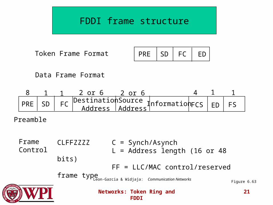
SDDestination
AddressSource Address
Information FCS
8 4
EDFC
2 or 6 2 or 61 11
FS
1
PRE
Preamble
SD FC EDToken Frame Format PRE
Frame Control
Data Frame Format
CLFFZZZZ C = Synch/Asynch L = Address length (16 or 48 bits)FF = LLC/MAC control/reserved frame type
Figure 6.63Leon-Garcia & Widjaja: Communication Networks
FDDI frame structure
Networks: Token Ring and FDDI
22
More FDDI Details• Transmission on optical fiber requires ASK• The simplest case: coding is done via the absence or
presence of a carrier signal {Intensity Modulation}.• Specific 5-bit codeword patterns chosen to guarantee
no more than three zeroes in a row to provide for adequate synchronization.
• 1300 nm wavelength specified.• Dual rings (primary and secondary) – transmit in
opposite directions.• Normally, second ring is idle and used for redundancy
for automatic repair (self-healing).
Networks: Token Ring and FDDI
23
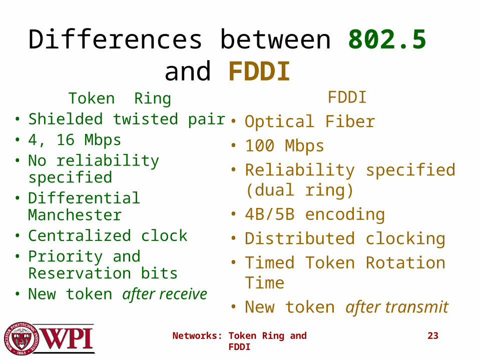
Differences between 802.5 and FDDI
Token Ring• Shielded twisted pair• 4, 16 Mbps• No reliability specified• Differential Manchester• Centralized clock• Priority and Reservation
bits• New token after receive
FDDI• Optical Fiber• 100 Mbps• Reliability specified (dual
ring)• 4B/5B encoding• Distributed clocking• Timed Token Rotation Time• New token after transmit
Top Related