


Languages
Pages
Legal

2: Application Layer 1
Chapter 2Application Layer
Computer Networking: A Top Down Approach, 5th edition. Jim Kurose, Keith RossAddison-Wesley, April 2009.
A note on the use of these ppt slides:We’re making these slides freely available to all (faculty, students, readers). They’re in PowerPoint form so you can add, modify, and delete slides (including this one) and slide content to suit your needs. They obviously represent a lot of work on our part. In return for use, we only ask the following: If you use these slides (e.g., in a class) in substantially unaltered form,
that you mention their source (after all, we’d like people to use our book!) If you post any slides in substantially unaltered form on a www site, that
you note that they are adapted from (or perhaps identical to) our slides, and note our copyright of this material.
Thanks and enjoy! JFK/KWR
All material copyright 1996-2009J.F Kurose and K.W. Ross, All Rights Reserved
2: Application Layer 2
2: Application Layer 3
Chapter 2: Application layer 2.1 Principles of network applications 2.2 Web and HTTP 2.3 FTP 2.4 Electronic Mail
SMTP, POP3, IMAP 2.5 DNS
2.6 P2P applications 2.7 Socket
programming with UDP
2.8 Socket programming with TCP
2: Application Layer 4
Chapter 2: Application LayerOur goals: conceptual,
implementation aspects of network application protocols transport-layer
service models client-server
paradigm peer-to-peer
paradigm
learn about protocols by examining popular application-level protocols HTTP FTP SMTP / POP3 / IMAP DNS
programming network applications socket API
2: Application Layer 5
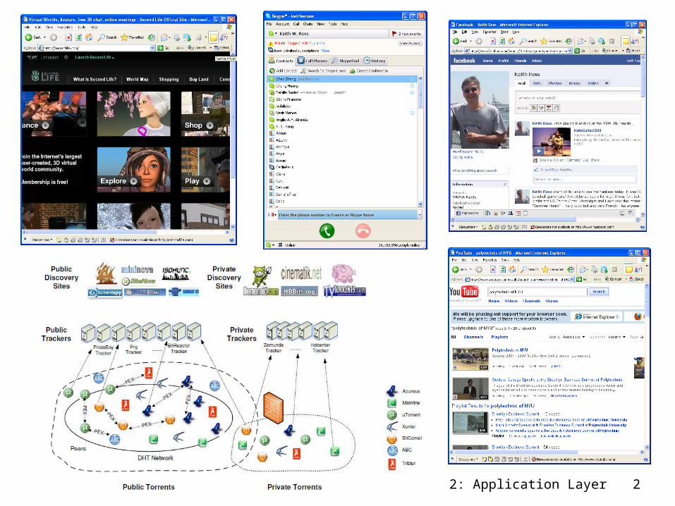
Some network apps e-mail web instant messaging remote login P2P file sharing multi-user network games streaming stored video clips
social networks voice over IP real-time video conferencing grid computing
2: Application Layer 6
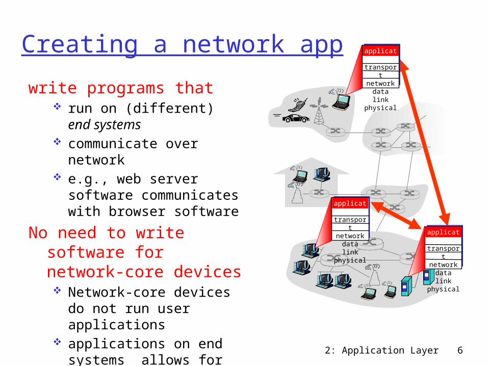
Creating a network appwrite programs that
run on (different) end systems
communicate over network
e.g., web server software communicates with browser software
No need to write software for network-core devices Network-core devices do
not run user applications applications on end
systems allows for rapid app development, propagation
application
transportnetworkdata linkphysical
application
transportnetworkdata linkphysical
application
transportnetworkdata linkphysical
2: Application Layer 7
Chapter 2: Application layer 2.1 Principles of network applications 2.2 Web and HTTP 2.3 FTP 2.4 Electronic Mail
SMTP, POP3, IMAP 2.5 DNS
2.6 P2P applications 2.7 Socket
programming with UDP
2.8 Socket programming with TCP
2: Application Layer 8
Application architectures Client-server
Including data centers / cloud computing Peer-to-peer (P2P) Hybrid of client-server and P2P

2: Application Layer 9
Client-server architectureserver:
always-on host permanent IP
address server farms for
scalingclients:
communicate with server
may be intermittently connected
may have dynamic IP addresses
do not communicate directly with each other
client/server
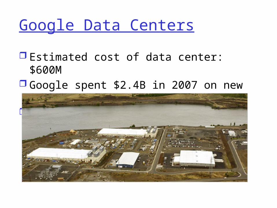
Google Data Centers Estimated cost of data center: $600M Google spent $2.4B in 2007 on new
data centers Each data center uses 50-100
megawatts of power
2: Application Layer 11
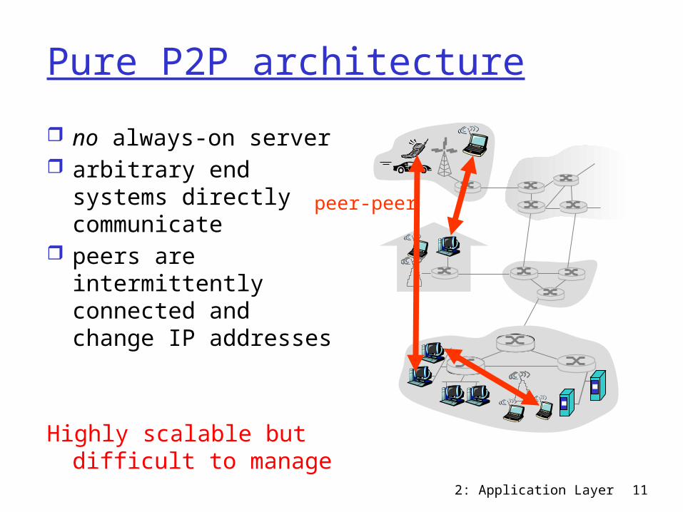
Pure P2P architecture no always-on server arbitrary end systems
directly communicate peers are
intermittently connected and change IP addresses
Highly scalable but difficult to manage
peer-peer
2: Application Layer 12
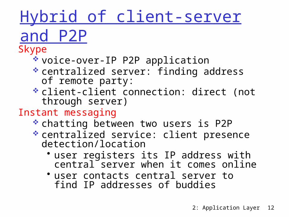
Hybrid of client-server and P2PSkype
voice-over-IP P2P application centralized server: finding address of
remote party: client-client connection: direct (not through
server) Instant messaging
chatting between two users is P2P centralized service: client presence
detection/location• user registers its IP address with central
server when it comes online• user contacts central server to find IP
addresses of buddies
2: Application Layer 13
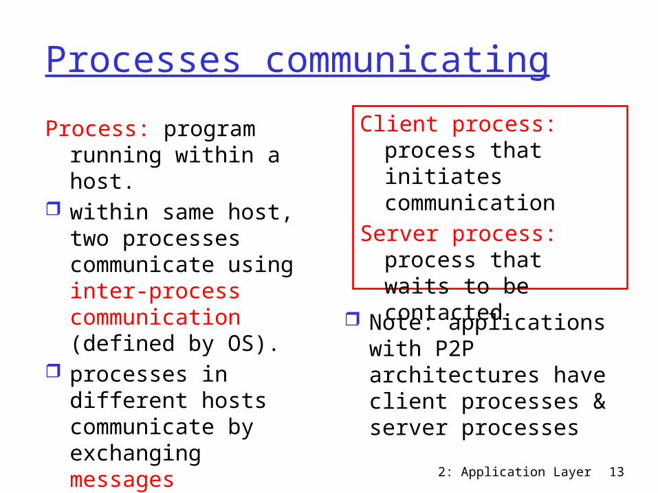
Processes communicatingProcess: program
running within a host. within same host, two
processes communicate using inter-process communication (defined by OS).
processes in different hosts communicate by exchanging messages
Client process: process that initiates communication
Server process: process that waits to be contacted
Note: applications with P2P architectures have client processes & server processes
2: Application Layer 14
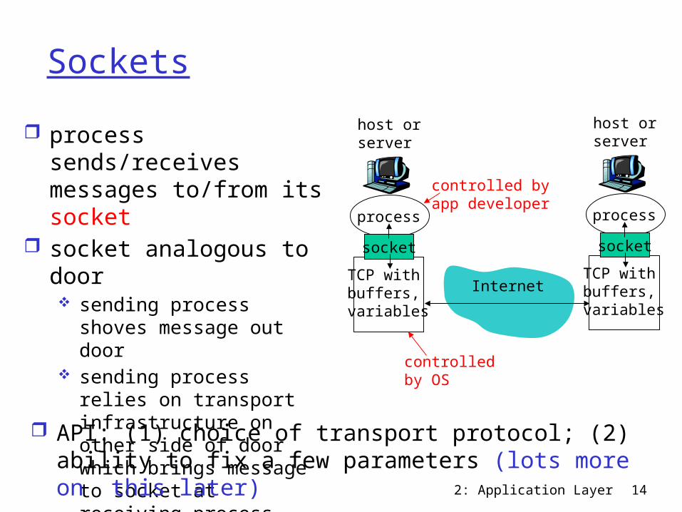
Sockets process sends/receives
messages to/from its socket
socket analogous to door sending process shoves
message out door sending process relies on
transport infrastructure on other side of door which brings message to socket at receiving process
process
TCP withbuffers,variables
socket
host orserver
process
TCP withbuffers,variables
socket
host orserver
Internet
controlledby OS
controlled byapp developer
API: (1) choice of transport protocol; (2) ability to fix a few parameters (lots more on this later)
2: Application Layer 15
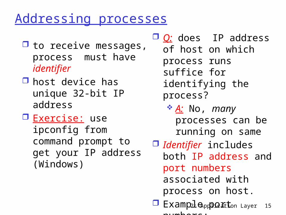
Addressing processes to receive messages,
process must have identifier
host device has unique 32-bit IP address
Exercise: use ipconfig from command prompt to get your IP address (Windows)
Q: does IP address of host on which process runs suffice for identifying the process? A: No, many
processes can be running on same
Identifier includes both IP address and port numbers associated with process on host.
Example port numbers: HTTP server: 80 Mail server: 25

2: Application Layer 16
App-layer protocol defines Types of messages
exchanged, e.g., request, response
Message syntax: what fields in
messages & how fields are delineated
Message semantics meaning of information
in fields Rules for when and
how processes send & respond to messages
Public-domain protocols:
defined in RFCs allows for
interoperability e.g., HTTP, SMTP,
BitTorrentProprietary protocols: e.g., Skype,
ppstream
2: Application Layer 17
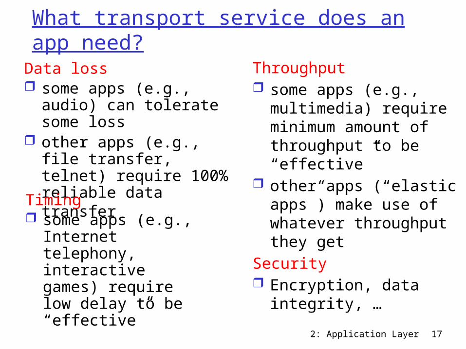
What transport service does an app need?
Data loss some apps (e.g., audio)
can tolerate some loss other apps (e.g., file
transfer, telnet) require 100% reliable data transfer
Timing some apps (e.g.,
Internet telephony, interactive games) require low delay to be “effective”
Throughput some apps (e.g.,
multimedia) require minimum amount of throughput to be “effective”
other apps (“elastic apps”) make use of whatever throughput they get
Security Encryption, data
integrity, …
2: Application Layer 18
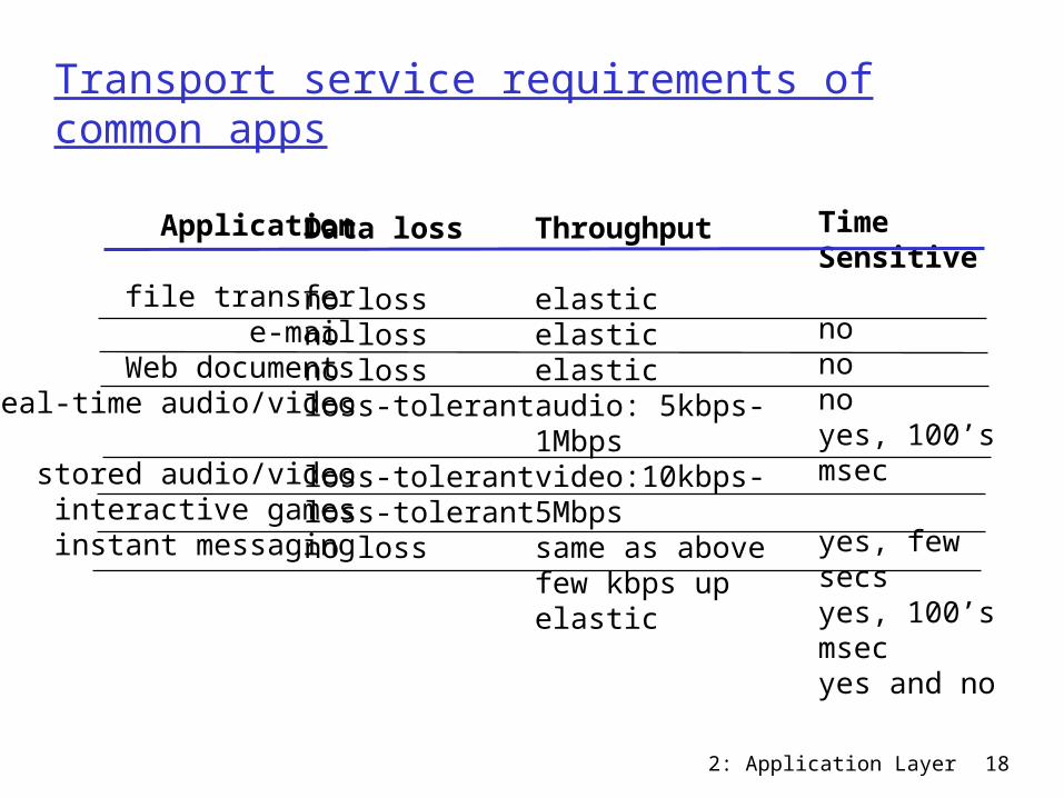
Transport service requirements of common apps
Application
file transfere-mail
Web documentsreal-time audio/video
stored audio/videointeractive gamesinstant messaging
Data loss
no lossno lossno lossloss-tolerant
loss-tolerantloss-tolerantno loss
Throughput
elasticelasticelasticaudio: 5kbps-1Mbpsvideo:10kbps-5Mbpssame as above few kbps upelastic
Time Sensitive
nononoyes, 100’s msec
yes, few secsyes, 100’s msecyes and no
2: Application Layer 19
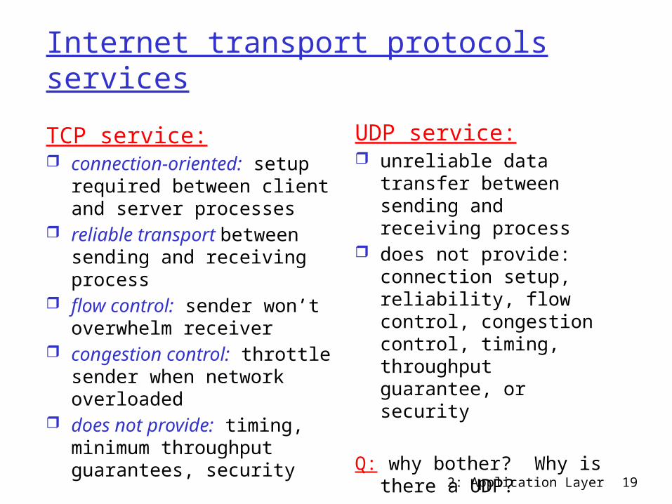
Internet transport protocols services
TCP service: connection-oriented: setup
required between client and server processes
reliable transport between sending and receiving process
flow control: sender won’t overwhelm receiver
congestion control: throttle sender when network overloaded
does not provide: timing, minimum throughput guarantees, security
UDP service: unreliable data transfer
between sending and receiving process
does not provide: connection setup, reliability, flow control, congestion control, timing, throughput guarantee, or security
Q: why bother? Why is there a UDP?

2: Application Layer 20
Internet apps: application, transport protocols
Application
e-mailremote terminal access
Web file transfer
streaming multimedia
Internet telephony
Applicationlayer protocol
SMTP [RFC 2821]Telnet [RFC 854]HTTP [RFC 2616]FTP [RFC 959]HTTP (eg Youtube), RTP [RFC 1889]SIP, RTP, proprietary(e.g., Skype)
Underlyingtransport protocol
TCPTCPTCPTCPTCP or UDP
typically UDP

2: Application Layer 21
Chapter 2: Application layer 2.1 Principles of network applications 2.2 Web and HTTP 2.3 FTP 2.4 Electronic Mail
SMTP, POP3, IMAP 2.5 DNS
2.6 P2P applications 2.7 Socket
programming with UDP
2.8 Socket programming with TCP

2: Application Layer 22
Web and HTTPFirst some jargon Web page consists of objects Object can be HTML file, JPEG image, Java
applet, audio file,… Web page consists of base HTML-file which
includes several referenced objects Each object is addressable by a URL Example URL:
www.someschool.edu/someDept/pic.gif
host name path name
2: Application Layer 23
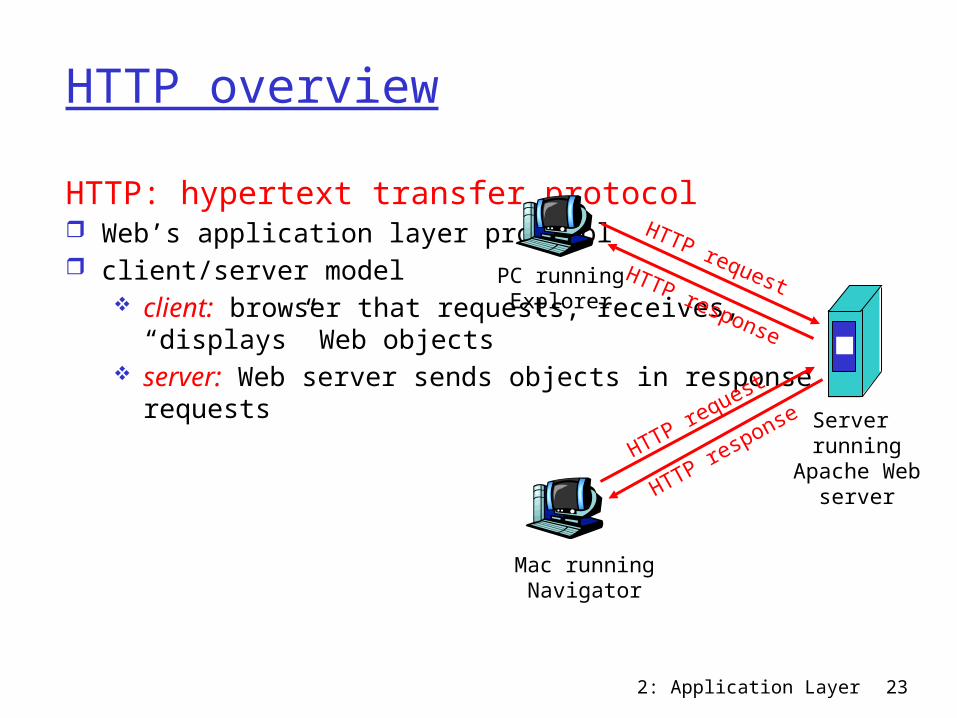
HTTP overviewHTTP: hypertext transfer protocol Web’s application layer protocol client/server model
client: browser that requests, receives, “displays” Web objects
server: Web server sends objects in response to requests
PC runningExplorer
Server running
Apache Webserver
Mac runningNavigator
HTTP request
HTTP request
HTTP response
HTTP response
2: Application Layer 24
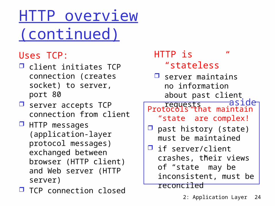
HTTP overview (continued)Uses TCP: client initiates TCP
connection (creates socket) to server, port 80
server accepts TCP connection from client
HTTP messages (application-layer protocol messages) exchanged between browser (HTTP client) and Web server (HTTP server)
TCP connection closed
HTTP is “stateless” server maintains no
information about past client requests
Protocols that maintain “state” are complex!
past history (state) must be maintained
if server/client crashes, their views of “state” may be inconsistent, must be reconciled
aside
2: Application Layer 25
HTTP connectionsNonpersistent HTTP At most one object is sent over a TCP
connection.
Persistent HTTP Multiple objects can be sent over single TCP
connection between client and server.
2: Application Layer 26
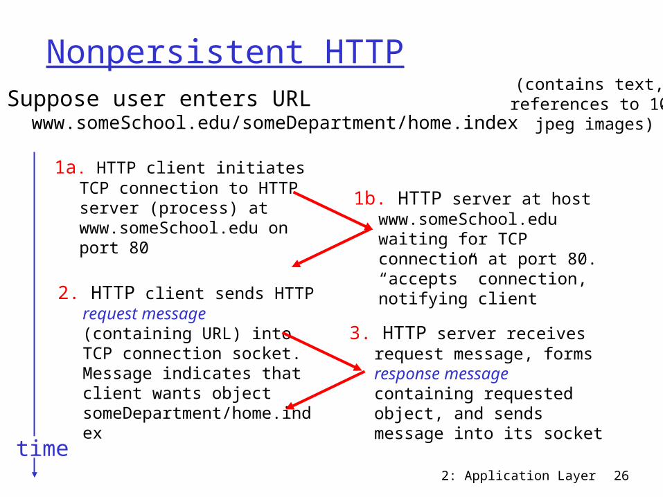
Nonpersistent HTTPSuppose user enters URL
www.someSchool.edu/someDepartment/home.index
1a. HTTP client initiates TCP connection to HTTP server (process) at www.someSchool.edu on port 80
2. HTTP client sends HTTP request message (containing URL) into TCP connection socket. Message indicates that client wants object someDepartment/home.index
1b. HTTP server at host www.someSchool.edu waiting for TCP connection at port 80. “accepts” connection, notifying client
3. HTTP server receives request message, forms response message containing requested object, and sends message into its sockettime
(contains text, references to 10
jpeg images)
2: Application Layer 27
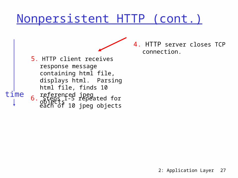
Nonpersistent HTTP (cont.)
5. HTTP client receives response message containing html file, displays html. Parsing html file, finds 10 referenced jpeg objects6. Steps 1-5 repeated for each of 10 jpeg objects
4. HTTP server closes TCP connection.
time
2: Application Layer 28
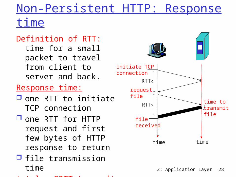
Non-Persistent HTTP: Response timeDefinition of RTT: time for
a small packet to travel from client to server and back.
Response time: one RTT to initiate TCP
connection one RTT for HTTP
request and first few bytes of HTTP response to return
file transmission timetotal = 2RTT+transmit
time
time to transmit file
initiate TCPconnection
RTTrequestfile
RTT
filereceived
time time
2: Application Layer 29
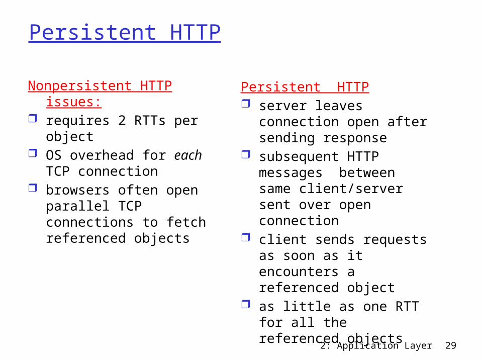
Persistent HTTP
Nonpersistent HTTP issues: requires 2 RTTs per object OS overhead for each TCP
connection browsers often open
parallel TCP connections to fetch referenced objects
Persistent HTTP server leaves connection
open after sending response
subsequent HTTP messages between same client/server sent over open connection
client sends requests as soon as it encounters a referenced object
as little as one RTT for all the referenced objects
2: Application Layer 30
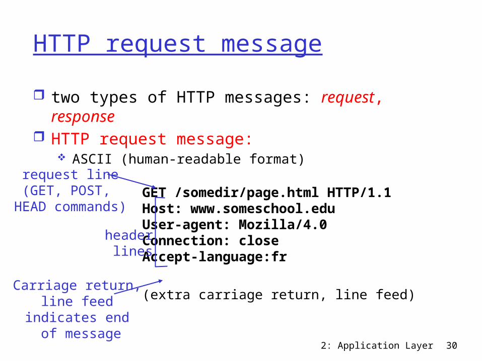
HTTP request message two types of HTTP messages: request,
response HTTP request message:
ASCII (human-readable format)
GET /somedir/page.html HTTP/1.1Host: www.someschool.edu User-agent: Mozilla/4.0Connection: close Accept-language:fr
(extra carriage return, line feed)
request line(GET, POST,
HEAD commands)
header lines
Carriage return, line feed
indicates end of message
2: Application Layer 31
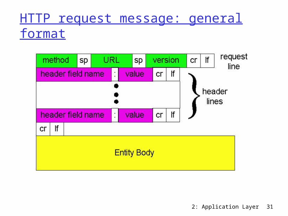
HTTP request message: general format

2: Application Layer 32
Uploading form inputPost method: Web page often includes form input Input is uploaded to server in entity bodyURL method:
Uses GET method Input is uploaded in
URL field of request line:
www.somesite.com/animalsearch?monkeys&banana
2: Application Layer 33
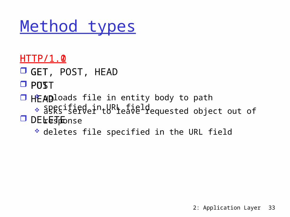
Method typesHTTP/1.0 GET POST HEAD
asks server to leave requested object out of response
HTTP/1.1 GET, POST, HEAD PUT
uploads file in entity body to path specified in URL field
DELETE deletes file specified in the URL field
2: Application Layer 34
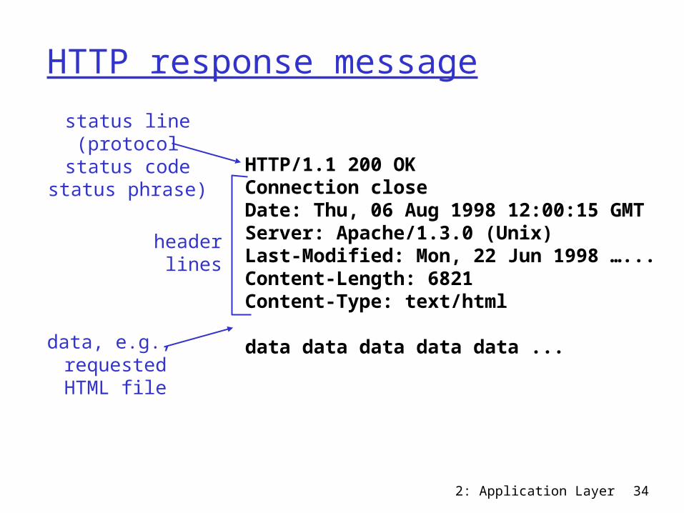
HTTP response message
HTTP/1.1 200 OK Connection closeDate: Thu, 06 Aug 1998 12:00:15 GMT Server: Apache/1.3.0 (Unix) Last-Modified: Mon, 22 Jun 1998 …... Content-Length: 6821 Content-Type: text/html data data data data data ...
status line(protocol
status codestatus phrase)
header lines
data, e.g., requestedHTML file
2: Application Layer 35
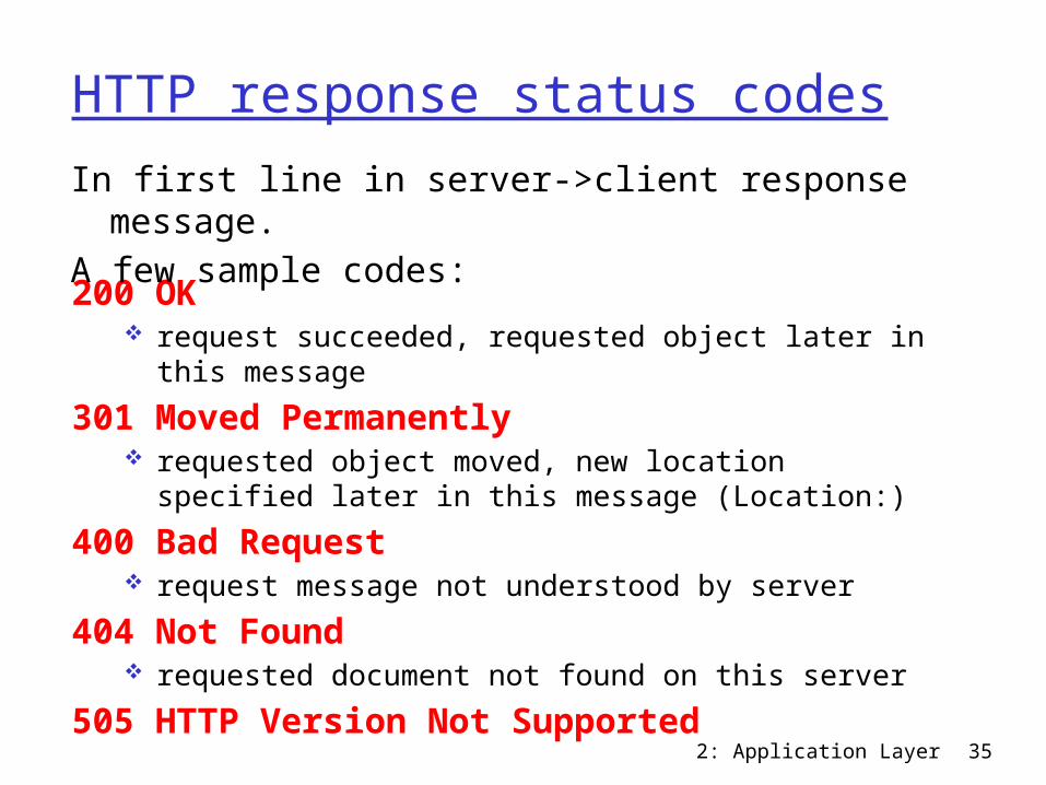
HTTP response status codes
200 OK request succeeded, requested object later in this
message301 Moved Permanently
requested object moved, new location specified later in this message (Location:)
400 Bad Request request message not understood by server
404 Not Found requested document not found on this server
505 HTTP Version Not Supported
In first line in server->client response message.A few sample codes:
2: Application Layer 36
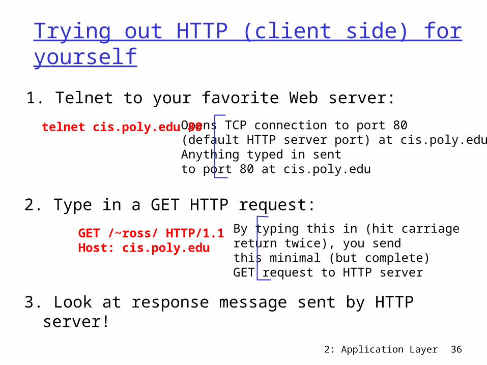
Trying out HTTP (client side) for yourself
1. Telnet to your favorite Web server:Opens TCP connection to port 80(default HTTP server port) at cis.poly.edu.Anything typed in sent to port 80 at cis.poly.edu
telnet cis.poly.edu 80
2. Type in a GET HTTP request:GET /~ross/ HTTP/1.1Host: cis.poly.edu
By typing this in (hit carriagereturn twice), you sendthis minimal (but complete) GET request to HTTP server
3. Look at response message sent by HTTP server!
2: Application Layer 37
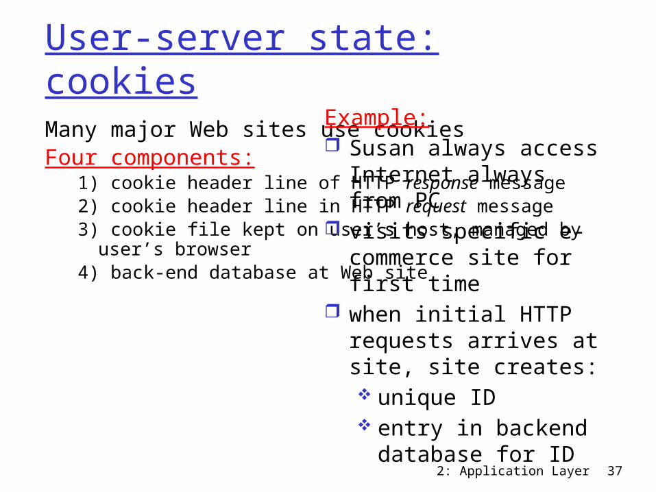
User-server state: cookiesMany major Web sites use cookiesFour components:
1) cookie header line of HTTP response message2) cookie header line in HTTP request message3) cookie file kept on user’s host, managed by user’s
browser4) back-end database at Web site
Example: Susan always access
Internet always from PC
visits specific e-commerce site for first time
when initial HTTP requests arrives at site, site creates: unique ID entry in backend
database for ID
2: Application Layer 38
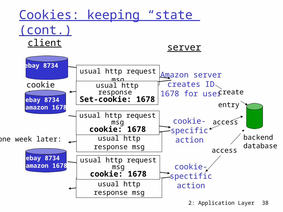
Cookies: keeping “state” (cont.)client server
usual http response msg
usual http response msg
cookie file
one week later:
usual http request msg
cookie: 1678cookie-specificaction
access
ebay 8734 usual http request msg Amazon server
creates ID1678 for usercreate
entryusual http response Set-cookie: 1678
ebay 8734amazon 1678
usual http request msg
cookie: 1678cookie-spectificaction
accessebay 8734amazon 1678
backenddatabase
2: Application Layer 39
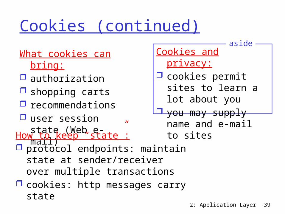
Cookies (continued)What cookies can
bring: authorization shopping carts recommendations user session state
(Web e-mail)
Cookies and privacy: cookies permit sites
to learn a lot about you
you may supply name and e-mail to sites
aside
How to keep “state”: protocol endpoints: maintain
state at sender/receiver over multiple transactions
cookies: http messages carry state
2: Application Layer 40
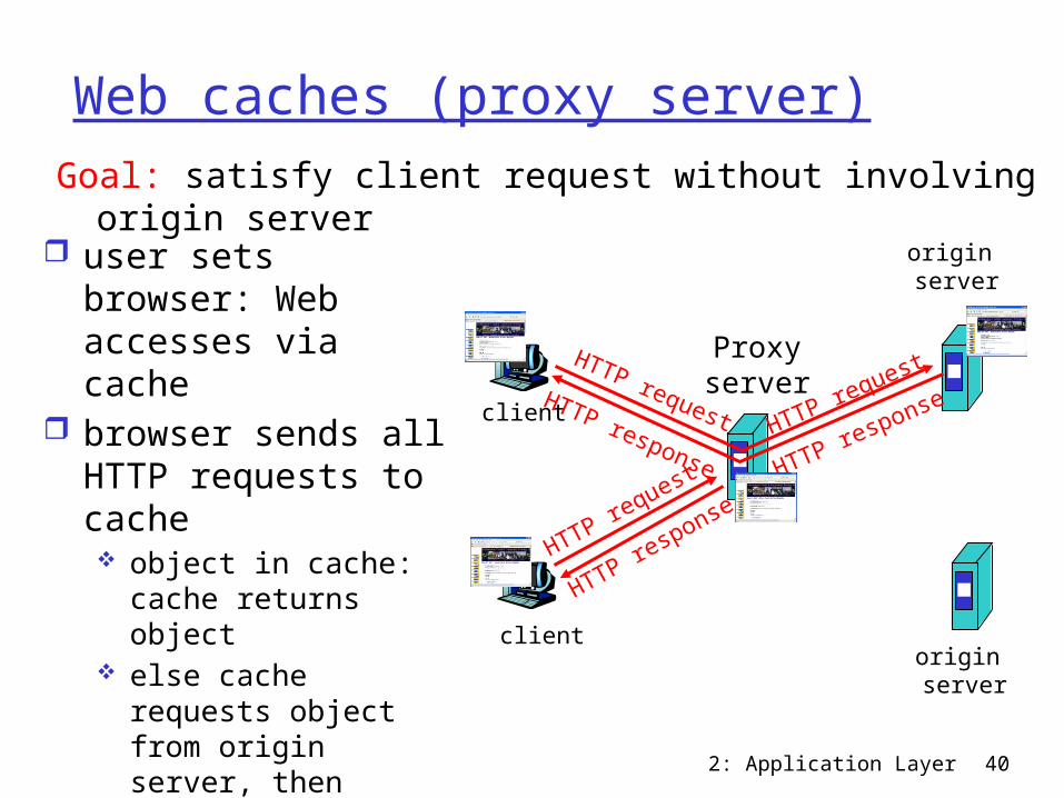
Web caches (proxy server)
user sets browser: Web accesses via cache
browser sends all HTTP requests to cache object in cache:
cache returns object else cache requests
object from origin server, then returns object to client
Goal: satisfy client request without involving origin server
client
Proxyserver
client
HTTP request
HTTP response
HTTP request HTTP request
origin server
origin server
HTTP response HTTP response

2: Application Layer 41
More about Web caching cache acts as both client and server typically cache is installed by ISP (university,
company, residential ISP)
Why Web caching? reduce response time for client request reduce traffic on an institution’s access link. Internet dense with caches: enables “poor”
content providers to effectively deliver content (but so does P2P file sharing)
2: Application Layer 42
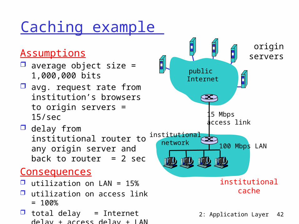
Caching example Assumptions average object size =
1,000,000 bits avg. request rate from
institution’s browsers to origin servers = 15/sec
delay from institutional router to any origin server and back to router = 2 sec
Consequences utilization on LAN = 15% utilization on access link =
100% total delay = Internet delay +
access delay + LAN delay = 2 sec + minutes +
milliseconds
originservers
public Internet
institutionalnetwork 100 Mbps LAN
15 Mbps access link
institutionalcache
2: Application Layer 43
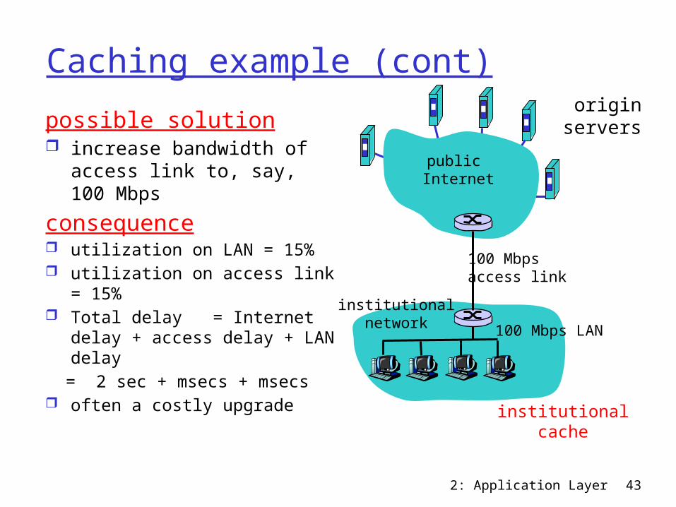
Caching example (cont)possible solution increase bandwidth of
access link to, say, 100 Mbps
consequence utilization on LAN = 15% utilization on access link =
15% Total delay = Internet delay +
access delay + LAN delay = 2 sec + msecs + msecs often a costly upgrade
originservers
public Internet
institutionalnetwork 100 Mbps LAN
100 Mbps access link
institutionalcache
2: Application Layer 44
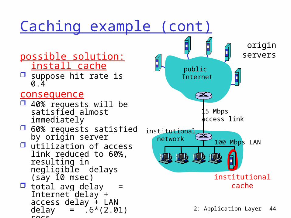
Caching example (cont)possible solution: install
cache suppose hit rate is 0.4consequence 40% requests will be
satisfied almost immediately
60% requests satisfied by origin server
utilization of access link reduced to 60%, resulting in negligible delays (say 10 msec)
total avg delay = Internet delay + access delay + LAN delay = .6*(2.01) secs + .4*milliseconds < 1.4 secs
originservers
public Internet
institutionalnetwork 100 Mbps LAN
15 Mbps access link
institutionalcache
2: Application Layer 45
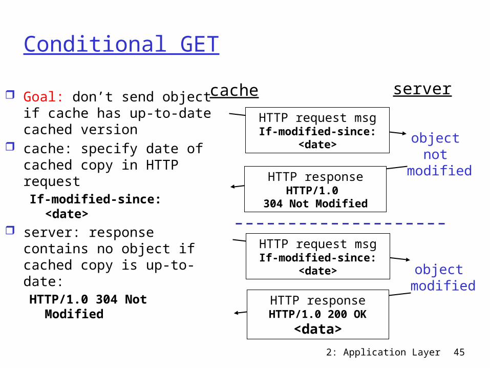
Conditional GET
Goal: don’t send object if cache has up-to-date cached version
cache: specify date of cached copy in HTTP requestIf-modified-since:
<date> server: response contains
no object if cached copy is up-to-date: HTTP/1.0 304 Not
Modified
cache serverHTTP request msgIf-modified-since:
<date>
HTTP responseHTTP/1.0
304 Not Modified
object not
modified
HTTP request msgIf-modified-since:
<date>
HTTP responseHTTP/1.0 200 OK
<data>
object modified
2: Application Layer 46
Chapter 2: Application layer 2.1 Principles of network applications 2.2 Web and HTTP 2.3 FTP 2.4 Electronic Mail
SMTP, POP3, IMAP 2.5 DNS
2.6 P2P applications 2.7 Socket
programming with UDP
2.8 Socket programming with TCP
2: Application Layer 47
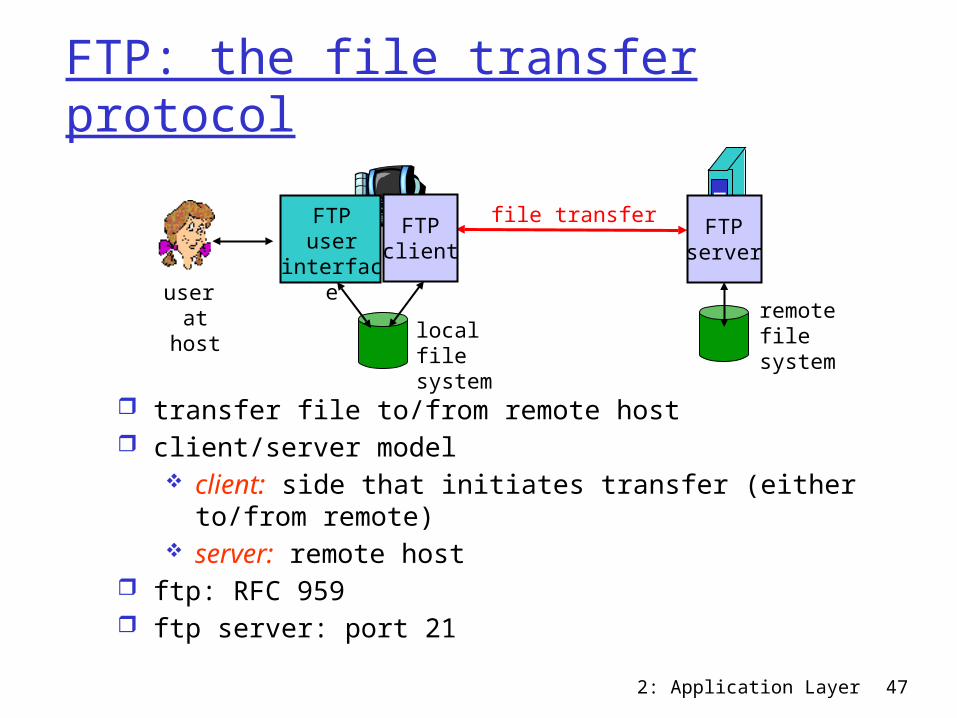
FTP: the file transfer protocol
transfer file to/from remote host client/server model
client: side that initiates transfer (either to/from remote)
server: remote host ftp: RFC 959 ftp server: port 21
file transfer FTPserver
FTPuser
interfaceFTP
client
local filesystem
remote filesystem
user at host
2: Application Layer 48
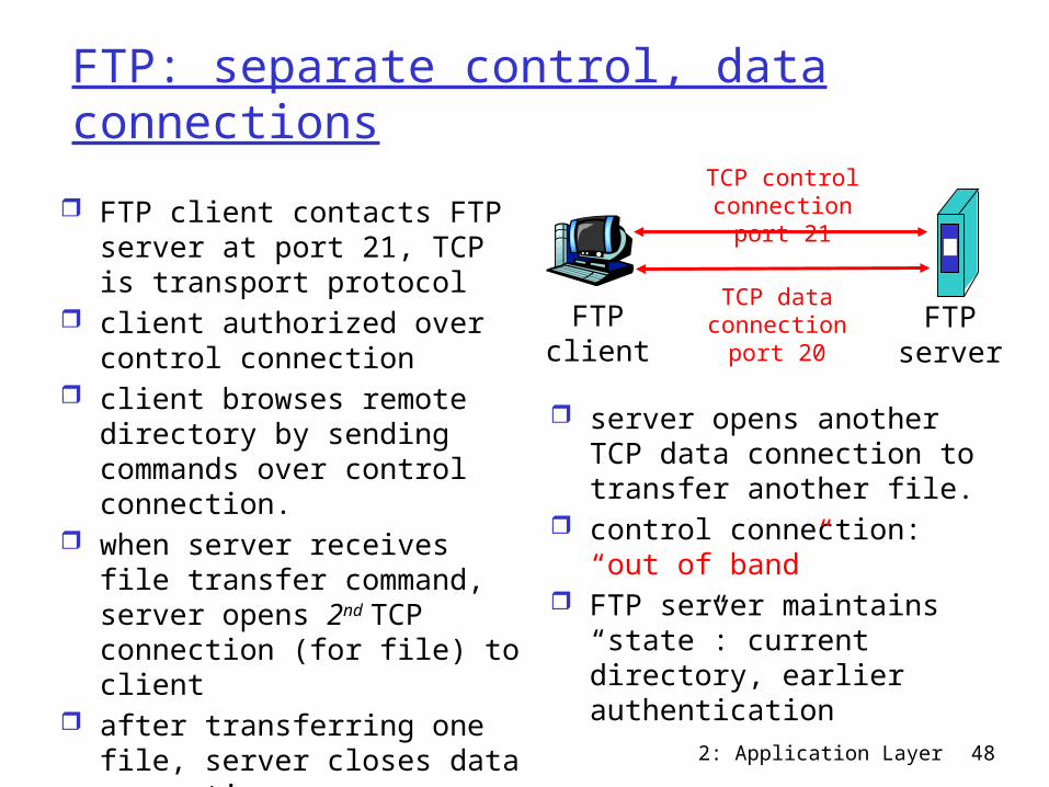
FTP: separate control, data connections
FTP client contacts FTP server at port 21, TCP is transport protocol
client authorized over control connection
client browses remote directory by sending commands over control connection.
when server receives file transfer command, server opens 2nd TCP connection (for file) to client
after transferring one file, server closes data connection.
FTPclient
FTPserver
TCP control connection
port 21
TCP data connectionport 20
server opens another TCP data connection to transfer another file.
control connection: “out of band”
FTP server maintains “state”: current directory, earlier authentication

2: Application Layer 49
FTP commands, responsesSample commands: sent as ASCII text over control channel USER username PASS password LIST return list of file in current directory RETR filename retrieves (gets) file STOR filename stores (puts) file onto remote host
Sample return codes status code and phrase (as in HTTP) 331 Username OK, password required 125 data connection already open; transfer
starting 425 Can’t open data connection 452 Error writing file
2: Application Layer 50
Chapter 2: Application layer 2.1 Principles of network applications 2.2 Web and HTTP 2.3 FTP 2.4 Electronic Mail
SMTP, POP3, IMAP 2.5 DNS
2.6 P2P applications 2.7 Socket
programming with UDP
2.8 Socket programming with TCP
2: Application Layer 51
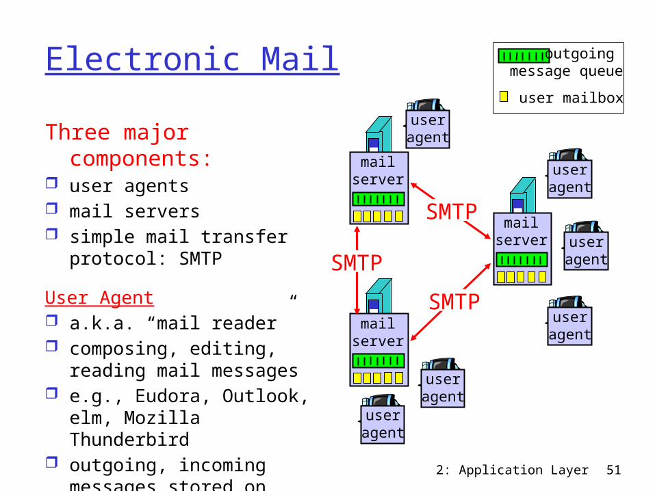
Electronic MailThree major
components: user agents mail servers simple mail transfer
protocol: SMTP
User Agent a.k.a. “mail reader” composing, editing,
reading mail messages e.g., Eudora, Outlook,
elm, Mozilla Thunderbird outgoing, incoming
messages stored on server
user mailbox
outgoing message queue
mailserver
useragent
useragent
useragentmail
server
useragent
useragent
mailserver
useragent
SMTP
SMTP
SMTP
2: Application Layer 52
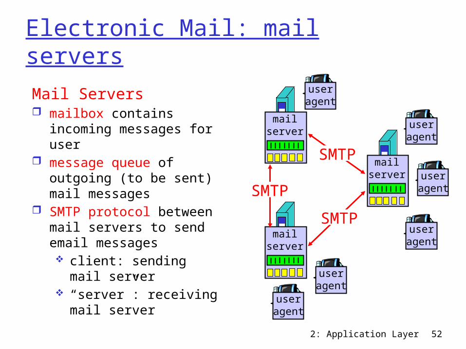
Electronic Mail: mail serversMail Servers mailbox contains
incoming messages for user
message queue of outgoing (to be sent) mail messages
SMTP protocol between mail servers to send email messages client: sending mail
server “server”: receiving
mail server
mailserver
useragent
useragent
useragentmail
server
useragent
useragent
mailserver
useragent
SMTP
SMTP
SMTP
2: Application Layer 53
Electronic Mail: SMTP [RFC 2821]
uses TCP to reliably transfer email message from client to server, port 25
direct transfer: sending server to receiving server three phases of transfer
handshaking (greeting) transfer of messages closure
command/response interaction commands: ASCII text response: status code and phrase
messages must be in 7-bit ASCII
2: Application Layer 54
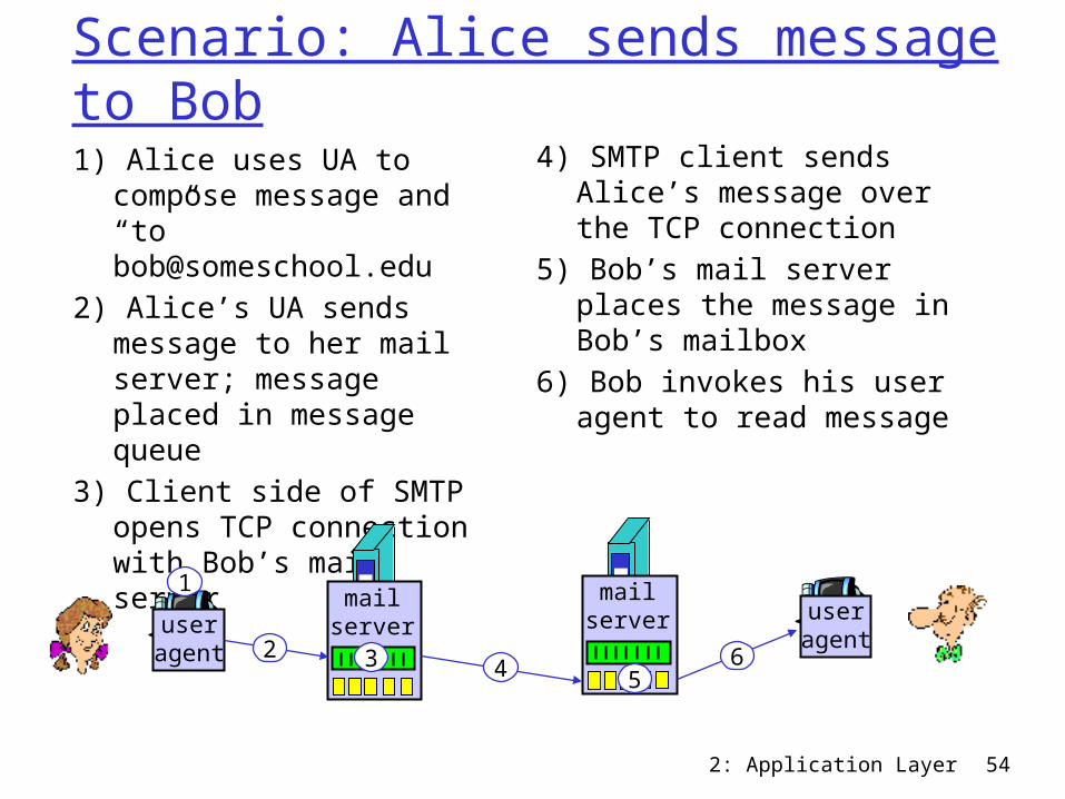
Scenario: Alice sends message to Bob1) Alice uses UA to compose
message and “to” [email protected]
2) Alice’s UA sends message to her mail server; message placed in message queue
3) Client side of SMTP opens TCP connection with Bob’s mail server
4) SMTP client sends Alice’s message over the TCP connection
5) Bob’s mail server places the message in Bob’s mailbox
6) Bob invokes his user agent to read message
useragent
mailserver
mailserver user
agent
1
2 3 4 56
2: Application Layer 55
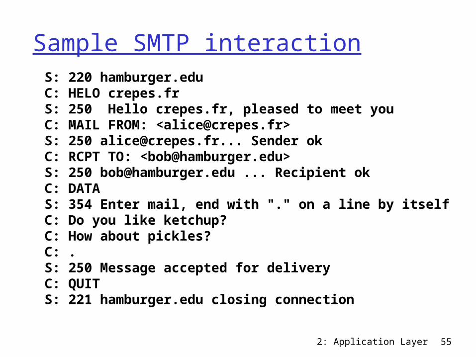
Sample SMTP interaction S: 220 hamburger.edu C: HELO crepes.fr S: 250 Hello crepes.fr, pleased to meet you C: MAIL FROM: <[email protected]> S: 250 [email protected]... Sender ok C: RCPT TO: <[email protected]> S: 250 [email protected] ... Recipient ok C: DATA S: 354 Enter mail, end with "." on a line by itself C: Do you like ketchup? C: How about pickles? C: . S: 250 Message accepted for delivery C: QUIT S: 221 hamburger.edu closing connection
2: Application Layer 56
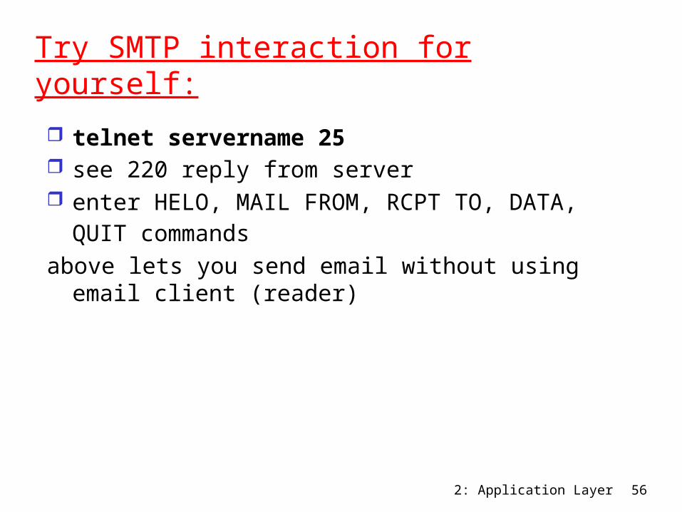
Try SMTP interaction for yourself:
telnet servername 25 see 220 reply from server enter HELO, MAIL FROM, RCPT TO, DATA, QUIT
commands above lets you send email without using email
client (reader)
2: Application Layer 57
SMTP: final words SMTP uses persistent connections SMTP requires message (header & body) to be in 7-bit
ASCII SMTP server uses CRLF.CRLF to determine end of
message
Comparison with HTTP: HTTP: pull SMTP: push both have ASCII command/response interaction, status
codes HTTP: each object encapsulated in its own response
msg SMTP: multiple objects sent in multipart msg
2: Application Layer 58
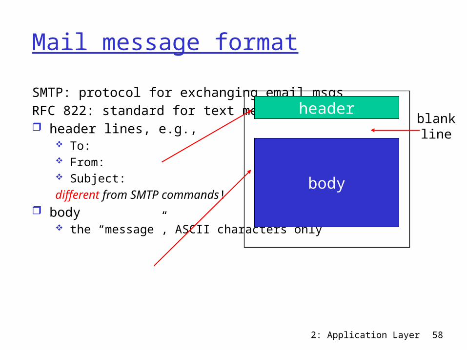
Mail message formatSMTP: protocol for exchanging email msgsRFC 822: standard for text message format: header lines, e.g.,
To: From: Subject:different from SMTP commands!
body the “message”, ASCII characters only
header
body
blankline
2: Application Layer 59
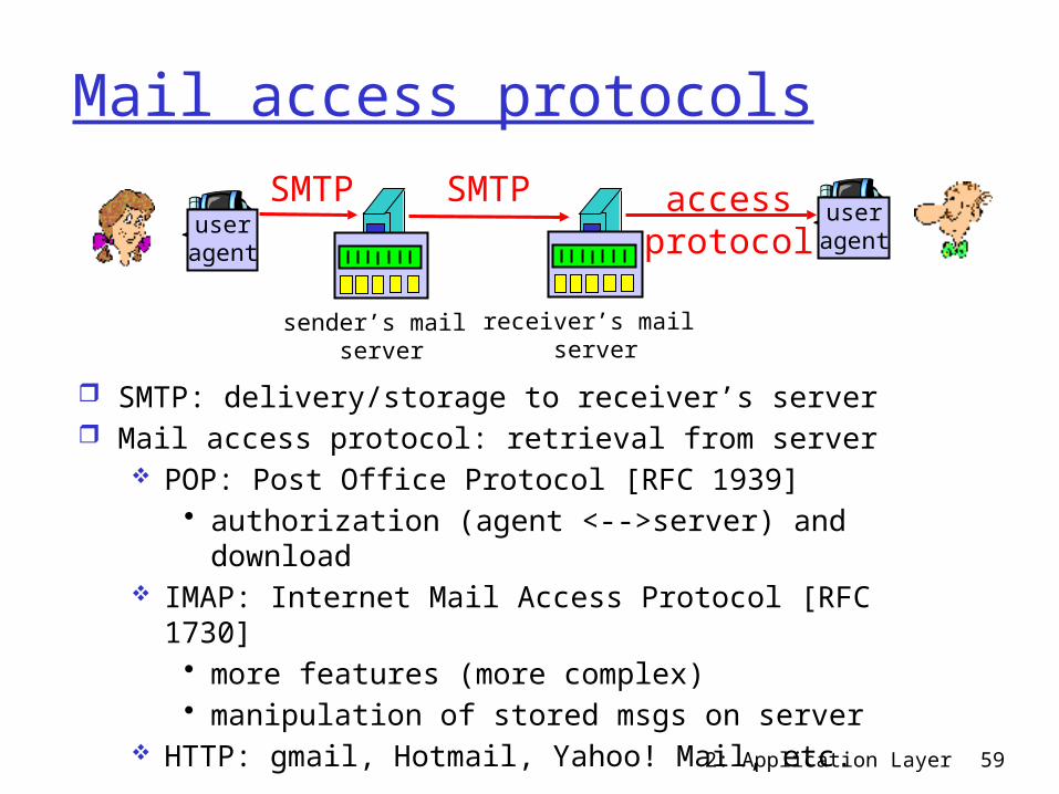
Mail access protocols
SMTP: delivery/storage to receiver’s server Mail access protocol: retrieval from server
POP: Post Office Protocol [RFC 1939]• authorization (agent <-->server) and
download IMAP: Internet Mail Access Protocol [RFC 1730]
• more features (more complex)• manipulation of stored msgs on server
HTTP: gmail, Hotmail, Yahoo! Mail, etc.
useragent
sender’s mail server
useragent
SMTP SMTP accessprotocol
receiver’s mail server
2: Application Layer 60
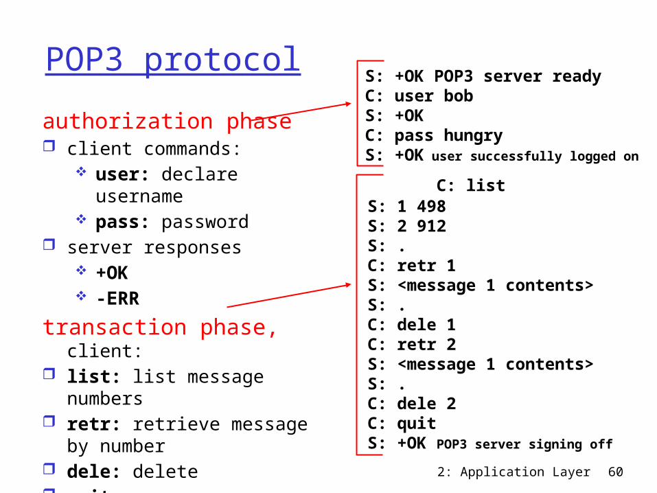
POP3 protocolauthorization phase client commands:
user: declare username
pass: password server responses
+OK -ERR
transaction phase, client: list: list message
numbers retr: retrieve message
by number dele: delete quit
C: list S: 1 498 S: 2 912 S: . C: retr 1 S: <message 1 contents> S: . C: dele 1 C: retr 2 S: <message 1 contents> S: . C: dele 2 C: quit S: +OK POP3 server signing off
S: +OK POP3 server ready C: user bob S: +OK C: pass hungry S: +OK user successfully logged on
2: Application Layer 61
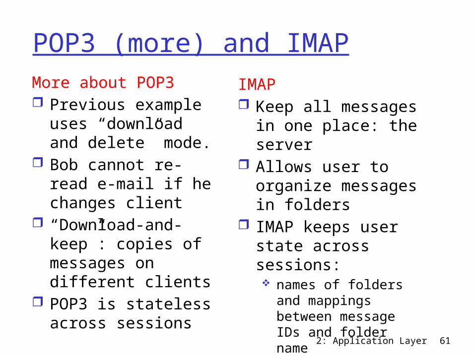
POP3 (more) and IMAPMore about POP3 Previous example
uses “download and delete” mode.
Bob cannot re-read e-mail if he changes client
“Download-and-keep”: copies of messages on different clients
POP3 is stateless across sessions
IMAP Keep all messages in
one place: the server Allows user to
organize messages in folders
IMAP keeps user state across sessions: names of folders and
mappings between message IDs and folder name
2: Application Layer 62
Chapter 2: Application layer 2.1 Principles of network applications 2.2 Web and HTTP 2.3 FTP 2.4 Electronic Mail
SMTP, POP3, IMAP 2.5 DNS
2.6 P2P applications 2.7 Socket
programming with UDP
2.8 Socket programming with TCP

2: Application Layer 63
DNS: Domain Name SystemPeople: many identifiers:
SSN, name, passport #Internet hosts, routers:
IP address (32 bit) - used for addressing datagrams “name”, e.g., ww.yahoo.com - used by humans
Q: map between IP addresses and name ?
Domain Name System: distributed database
implemented in hierarchy of many name servers
application-layer protocol host, routers, name servers to communicate to resolve names (address/name translation) note: core Internet
function, implemented as application-layer protocol
complexity at network’s “edge”
2: Application Layer 64
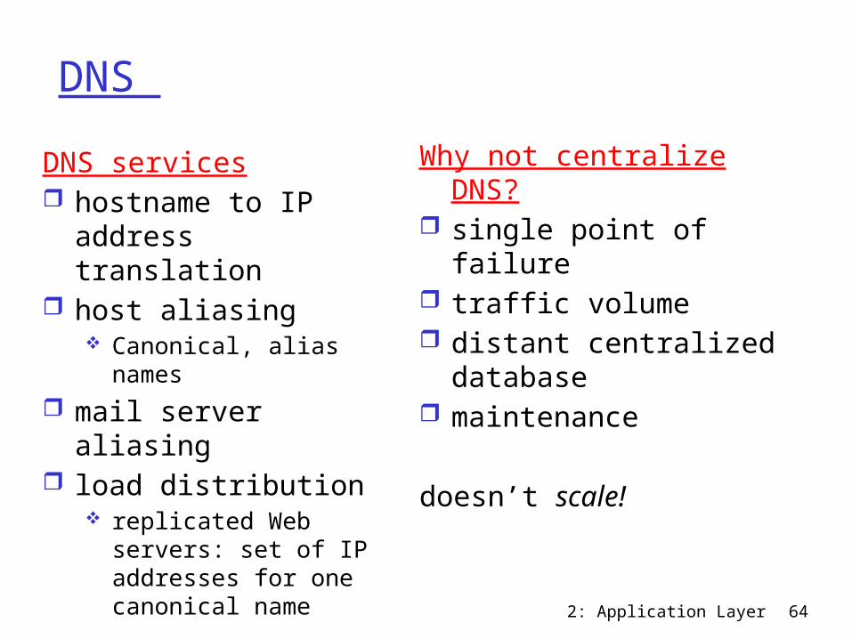
DNS Why not centralize DNS? single point of failure traffic volume distant centralized
database maintenance
doesn’t scale!
DNS services hostname to IP
address translation host aliasing
Canonical, alias names
mail server aliasing load distribution
replicated Web servers: set of IP addresses for one canonical name
2: Application Layer 65
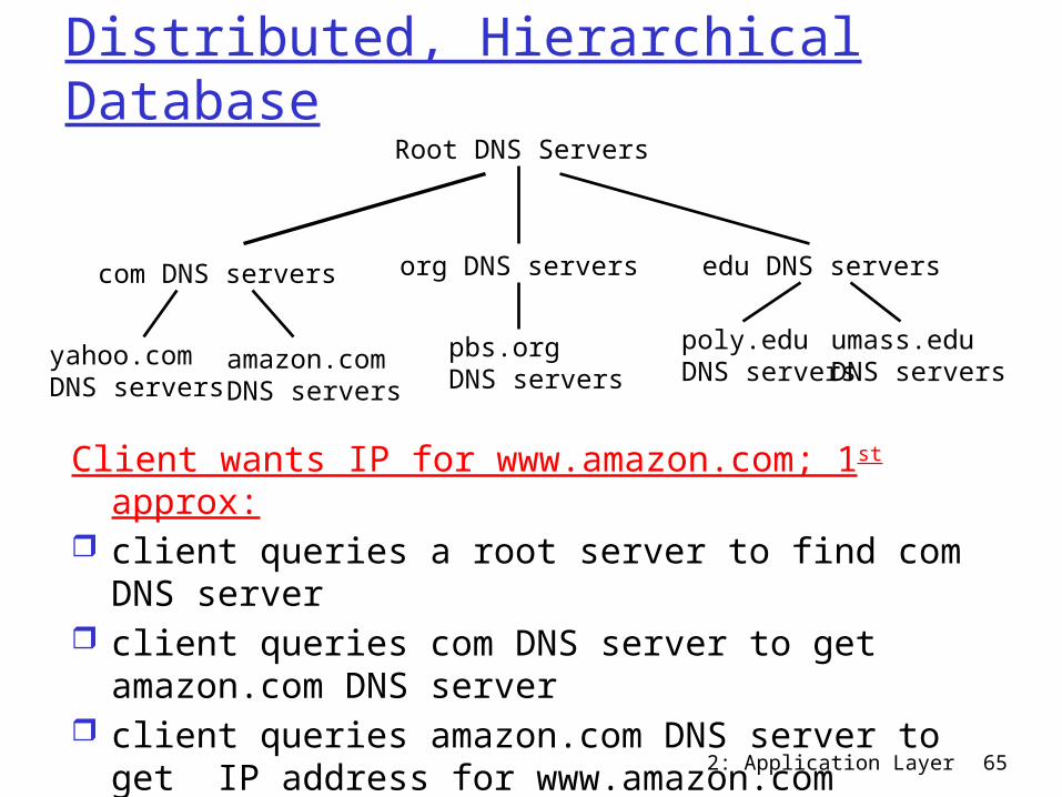
Root DNS Servers
com DNS servers org DNS servers edu DNS servers
poly.eduDNS servers
umass.eduDNS serversyahoo.com
DNS serversamazon.comDNS servers
pbs.orgDNS servers
Distributed, Hierarchical Database
Client wants IP for www.amazon.com; 1st approx: client queries a root server to find com DNS
server client queries com DNS server to get
amazon.com DNS server client queries amazon.com DNS server to get IP
address for www.amazon.com
2: Application Layer 66
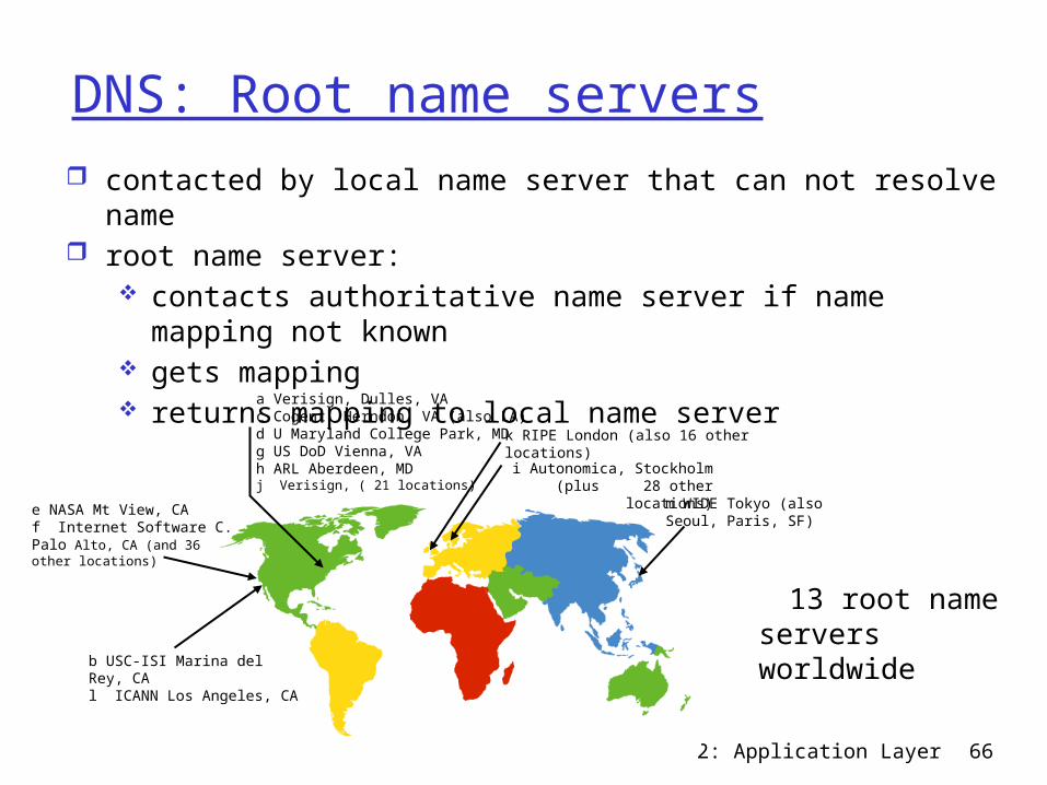
DNS: Root name servers contacted by local name server that can not resolve name root name server:
contacts authoritative name server if name mapping not known
gets mapping returns mapping to local name server
13 root name servers worldwideb USC-ISI Marina del Rey, CA
l ICANN Los Angeles, CA
e NASA Mt View, CAf Internet Software C. Palo Alto, CA (and 36 other locations)
i Autonomica, Stockholm (plus 28 other locations)
k RIPE London (also 16 other locations)
m WIDE Tokyo (also Seoul, Paris, SF)
a Verisign, Dulles, VAc Cogent, Herndon, VA (also LA)d U Maryland College Park, MDg US DoD Vienna, VAh ARL Aberdeen, MDj Verisign, ( 21 locations)
2: Application Layer 67
TLD and Authoritative Servers Top-level domain (TLD) servers:
responsible for com, org, net, edu, etc, and all top-level country domains uk, fr, ca, jp.
Network Solutions maintains servers for com TLD
Educause for edu TLD Authoritative DNS servers:
organization’s DNS servers, providing authoritative hostname to IP mappings for organization’s servers (e.g., Web, mail).
can be maintained by organization or service provider
2: Application Layer 68
Local Name Server does not strictly belong to hierarchy each ISP (residential ISP, company,
university) has one. also called “default name server”
when host makes DNS query, query is sent to its local DNS server acts as proxy, forwards query into hierarchy
2: Application Layer 69
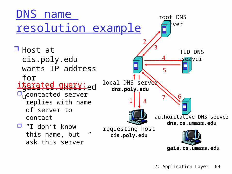
requesting hostcis.poly.edu
gaia.cs.umass.edu
root DNS server
local DNS serverdns.poly.edu
1
23
4
5
6
authoritative DNS serverdns.cs.umass.edu
78
TLD DNS server
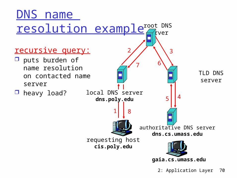
DNS name resolution example
Host at cis.poly.edu wants IP address for gaia.cs.umass.edu
iterated query: contacted server
replies with name of server to contact
“I don’t know this name, but ask this server”
2: Application Layer 70
requesting hostcis.poly.edu
gaia.cs.umass.edu
root DNS server
local DNS serverdns.poly.edu
1
2
45
6
authoritative DNS serverdns.cs.umass.edu
7
8
TLD DNS server
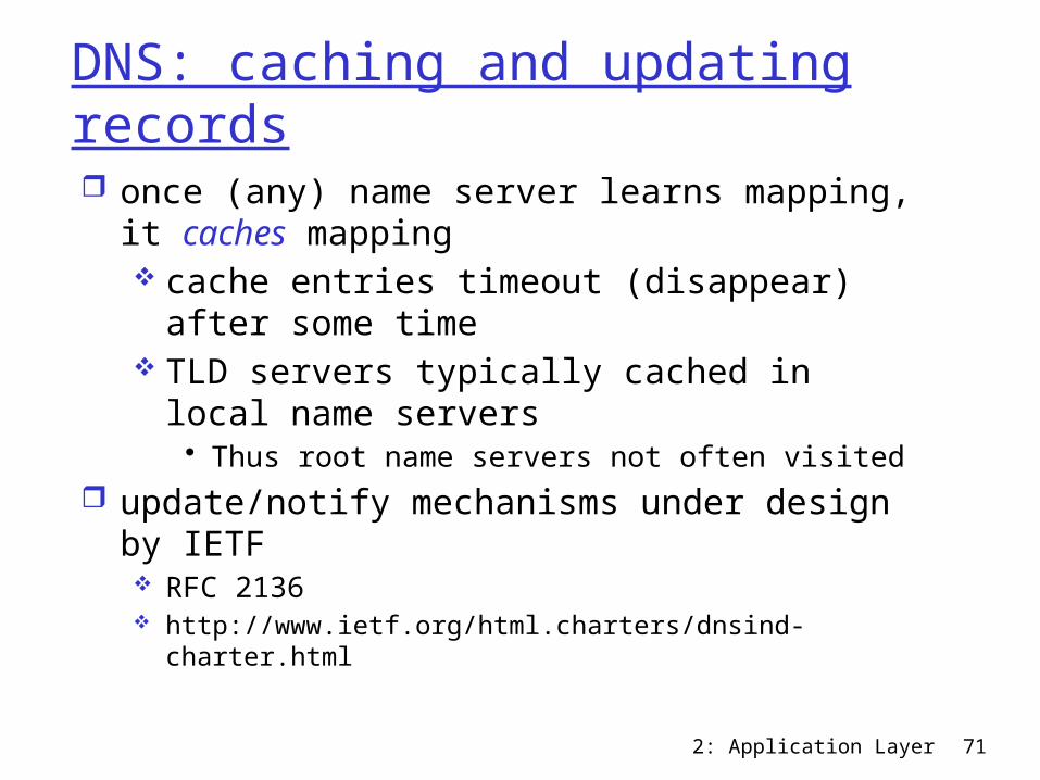
3recursive query: puts burden of
name resolution on contacted name server
heavy load?
DNS name resolution example
2: Application Layer 71
DNS: caching and updating records once (any) name server learns mapping, it
caches mapping cache entries timeout (disappear) after
some time TLD servers typically cached in local name
servers• Thus root name servers not often visited
update/notify mechanisms under design by IETF RFC 2136 http://www.ietf.org/html.charters/dnsind-charter.html
2: Application Layer 72
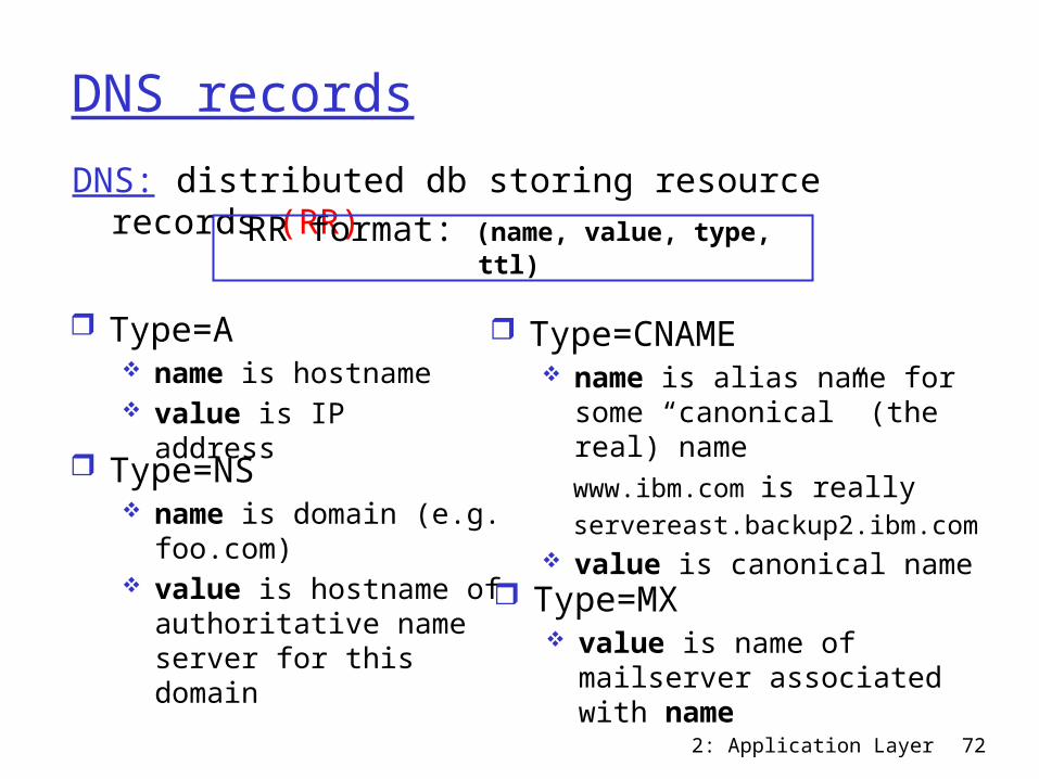
DNS recordsDNS: distributed db storing resource records (RR)
Type=NS name is domain (e.g.
foo.com) value is hostname of
authoritative name server for this domain
RR format: (name, value, type, ttl)
Type=A name is hostname value is IP address
Type=CNAME name is alias name for some
“canonical” (the real) name www.ibm.com is really servereast.backup2.ibm.com value is canonical name
Type=MX value is name of
mailserver associated with name
2: Application Layer 73
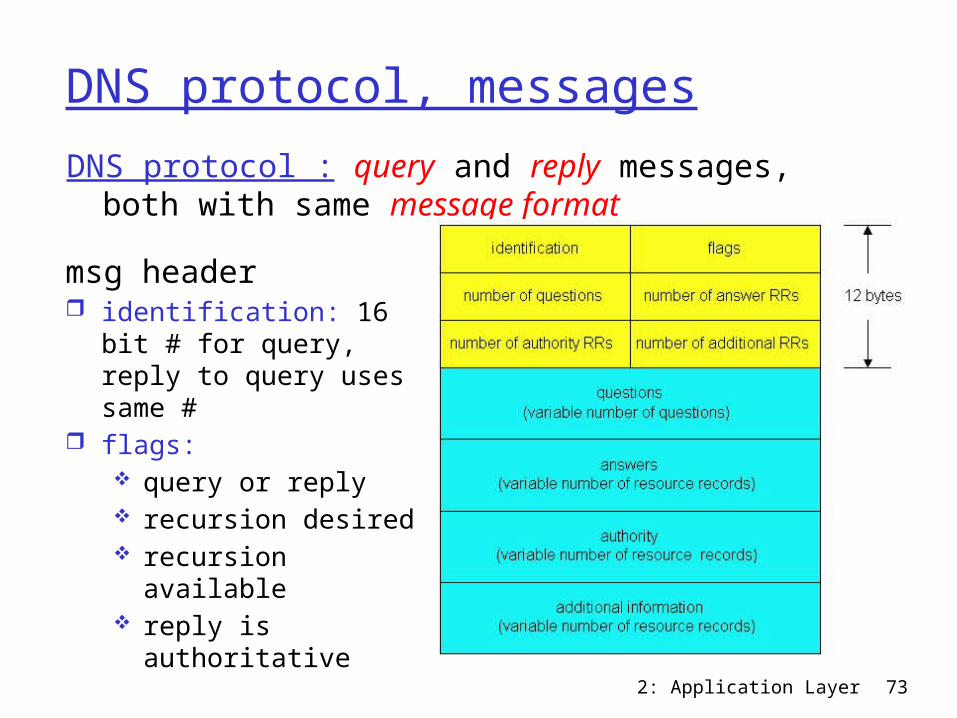
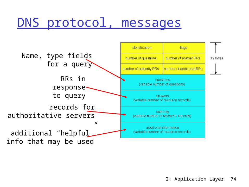
DNS protocol, messagesDNS protocol : query and reply messages, both
with same message format
msg header identification: 16 bit #
for query, reply to query uses same #
flags: query or reply recursion desired recursion available reply is authoritative
2: Application Layer 74
DNS protocol, messages
Name, type fields for a query
RRs in responseto query
records forauthoritative servers
additional “helpful”info that may be used
2: Application Layer 75
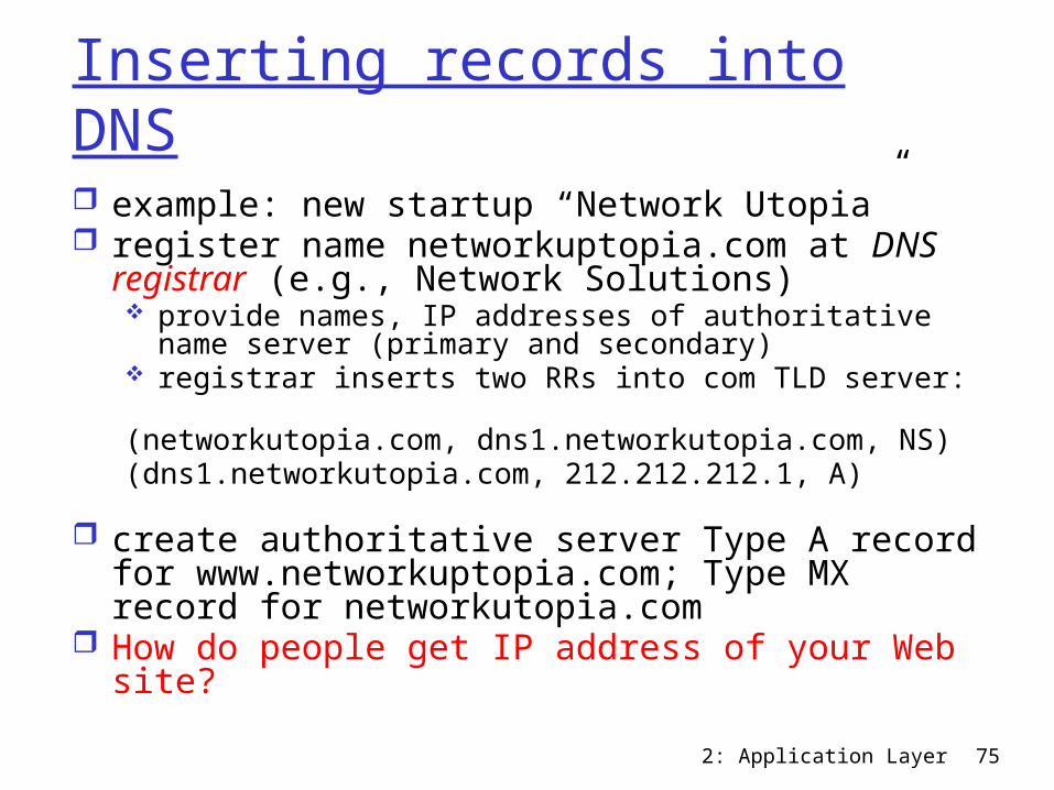
Inserting records into DNS example: new startup “Network Utopia” register name networkuptopia.com at DNS
registrar (e.g., Network Solutions) provide names, IP addresses of authoritative name
server (primary and secondary) registrar inserts two RRs into com TLD server:(networkutopia.com, dns1.networkutopia.com, NS)(dns1.networkutopia.com, 212.212.212.1, A)
create authoritative server Type A record for www.networkuptopia.com; Type MX record for networkutopia.com
How do people get IP address of your Web site?
2: Application Layer 76
Chapter 2: Application layer 2.1 Principles of network applications 2.2 Web and HTTP 2.3 FTP 2.4 Electronic Mail
SMTP, POP3, IMAP 2.5 DNS
2.6 P2P applications 2.7 Socket
programming with UDP
2.8 Socket programming with TCP
2: Application Layer 77
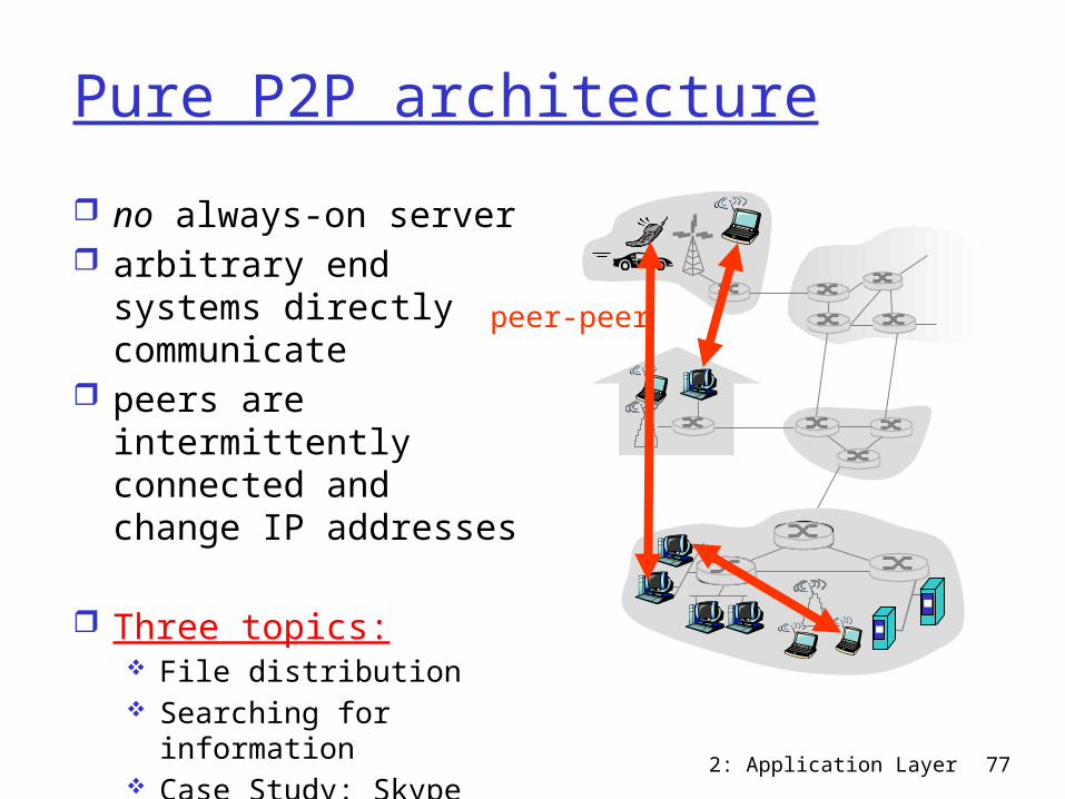
Pure P2P architecture no always-on server arbitrary end systems
directly communicate peers are
intermittently connected and change IP addresses
Three topics: File distribution Searching for
information Case Study: Skype
peer-peer
2: Application Layer 78
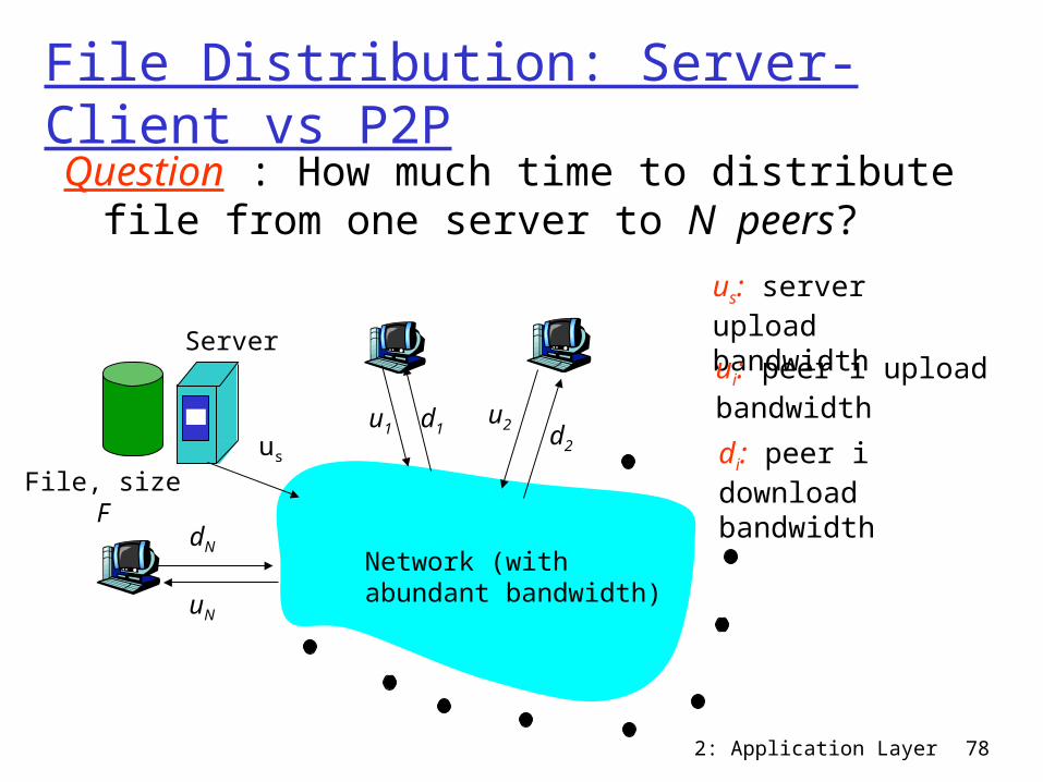
File Distribution: Server-Client vs P2PQuestion : How much time to distribute file
from one server to N peers?
us
u2d1 d2u1
uN
dN
Server
Network (with abundant bandwidth)
File, size F
us: server upload bandwidthui: peer i upload bandwidthdi: peer i download bandwidth
2: Application Layer 79
File distribution time: server-client
us
u2d1 d2u1
uN
dN
Server
Network (with abundant bandwidth)
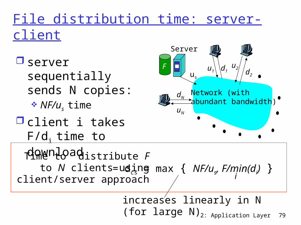
F server sequentially sends N copies: NF/us time
client i takes F/di time to download
increases linearly in N(for large N)
= dcs = max { NF/us, F/min(di) }i
Time to distribute F to N clients using
client/server approach
2: Application Layer 80
File distribution time: P2P
us
u2d1 d2u1
uN
dN
Server
Network (with abundant bandwidth)
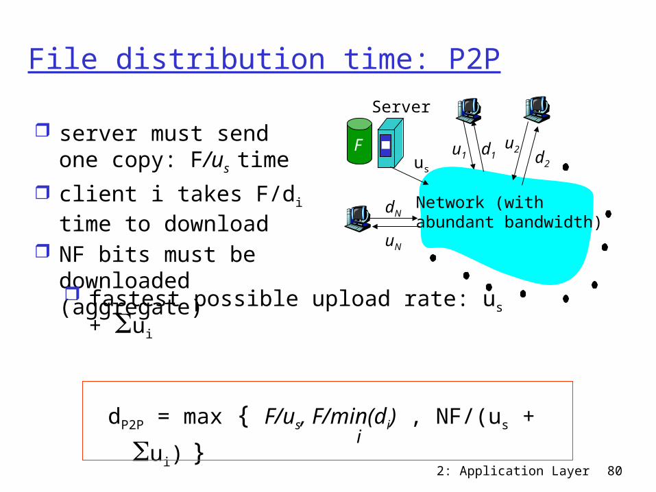
F server must send one
copy: F/us time client i takes F/di time
to download NF bits must be
downloaded (aggregate) fastest possible upload rate: us + Sui
dP2P = max { F/us, F/min(di) , NF/(us + Sui) }i
2: Application Layer 81
0
0.5
1
1.5
2
2.5
3
3.5
0 5 10 15 20 25 30 35
N
Min
imum
Dis
tribu
tion
Tim
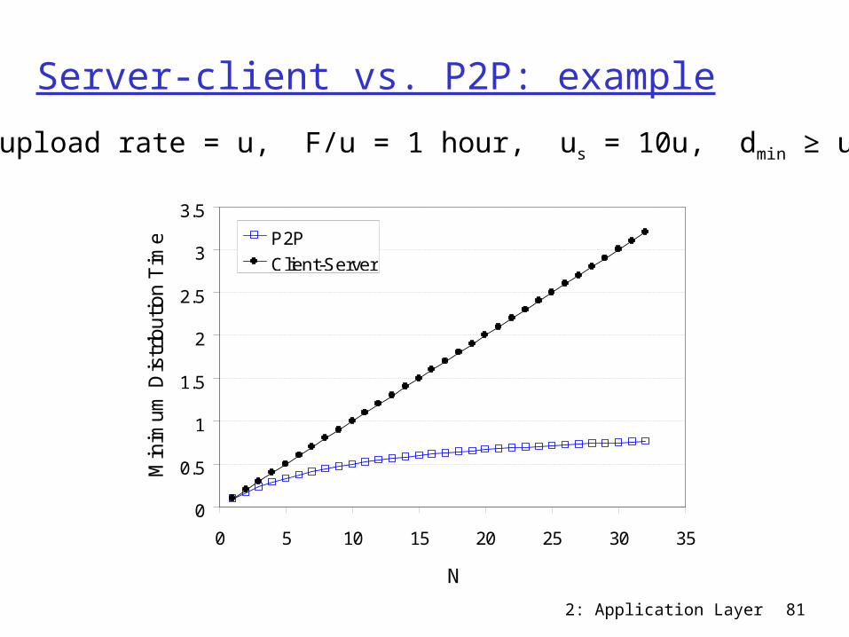
e P2PClient-Server
Server-client vs. P2P: exampleClient upload rate = u, F/u = 1 hour, us = 10u, dmin ≥ us
2: Application Layer 82
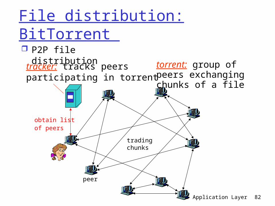
File distribution: BitTorrent
tracker: tracks peers participating in torrent
torrent: group of peers exchanging chunks of a file
obtain listof peers
trading chunks
peer
P2P file distribution
2: Application Layer 83
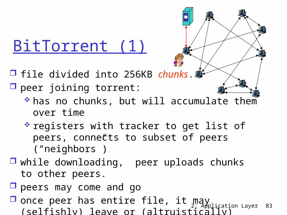
BitTorrent (1) file divided into 256KB chunks. peer joining torrent:
has no chunks, but will accumulate them over time
registers with tracker to get list of peers, connects to subset of peers (“neighbors”)
while downloading, peer uploads chunks to other peers.
peers may come and go once peer has entire file, it may (selfishly) leave
or (altruistically) remain
2: Application Layer 84
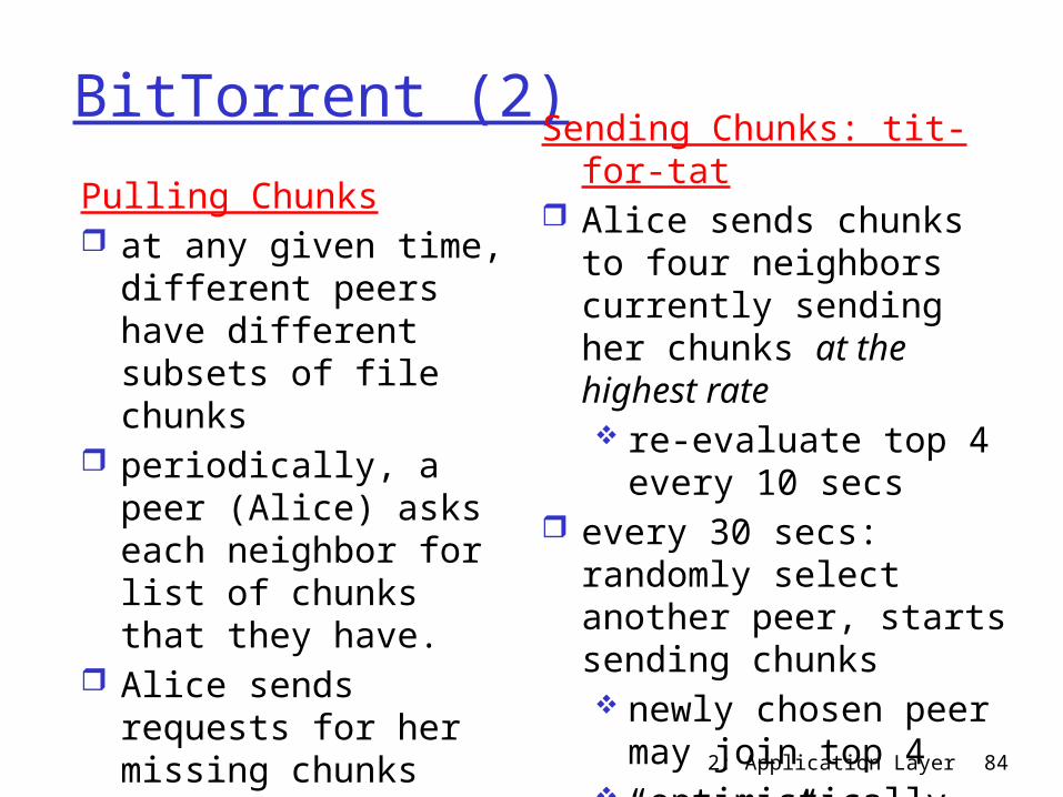
BitTorrent (2)Pulling Chunks at any given time,
different peers have different subsets of file chunks
periodically, a peer (Alice) asks each neighbor for list of chunks that they have.
Alice sends requests for her missing chunks rarest first
Sending Chunks: tit-for-tat Alice sends chunks to
four neighbors currently sending her chunks at the highest rate re-evaluate top 4
every 10 secs every 30 secs: randomly
select another peer, starts sending chunks newly chosen peer
may join top 4 “optimistically
unchoke”
2: Application Layer 85
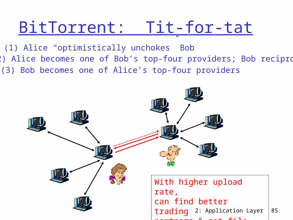
BitTorrent: Tit-for-tat(1) Alice “optimistically unchokes” Bob
(2) Alice becomes one of Bob’s top-four providers; Bob reciprocates(3) Bob becomes one of Alice’s top-four providers
With higher upload rate, can find better trading partners & get file faster!
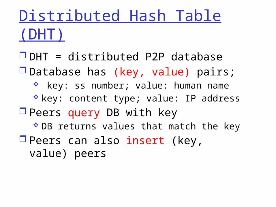
Distributed Hash Table (DHT) DHT = distributed P2P database Database has (key, value) pairs;
key: ss number; value: human name key: content type; value: IP address
Peers query DB with key DB returns values that match the key
Peers can also insert (key, value) peers
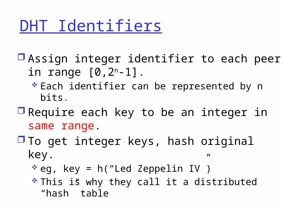
DHT Identifiers Assign integer identifier to each peer in
range [0,2n-1]. Each identifier can be represented by n bits.
Require each key to be an integer in same range.
To get integer keys, hash original key. eg, key = h(“Led Zeppelin IV”) This is why they call it a distributed “hash” table
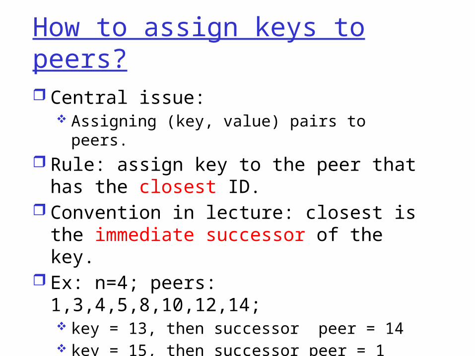
How to assign keys to peers? Central issue:
Assigning (key, value) pairs to peers. Rule: assign key to the peer that has the
closest ID. Convention in lecture: closest is the
immediate successor of the key. Ex: n=4; peers: 1,3,4,5,8,10,12,14;
key = 13, then successor peer = 14 key = 15, then successor peer = 1
1
3
4
5
810
12
15
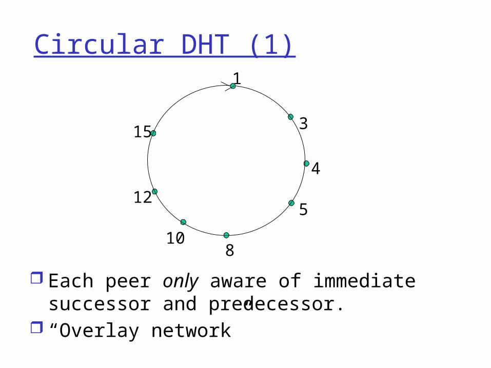
Circular DHT (1)
Each peer only aware of immediate successor and predecessor.
“Overlay network”
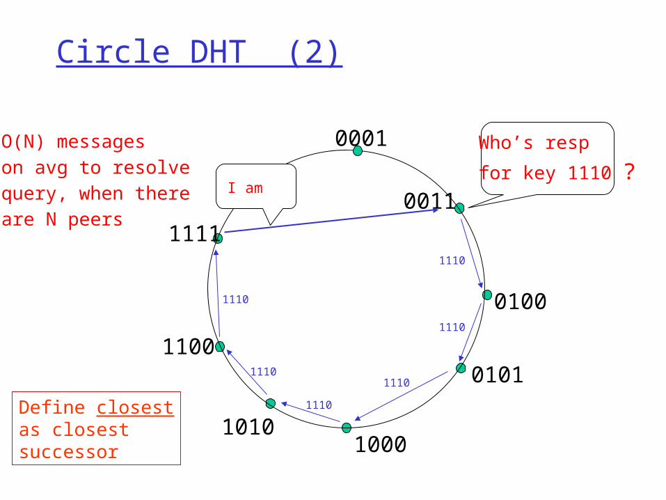
Circle DHT (2)
0001
0011
0100
0101
10001010
1100
1111
Who’s resp for key 1110 ?
I am
O(N) messageson avg to resolvequery, when thereare N peers
1110
1110
1110
1110
1110
1110
Define closestas closestsuccessor
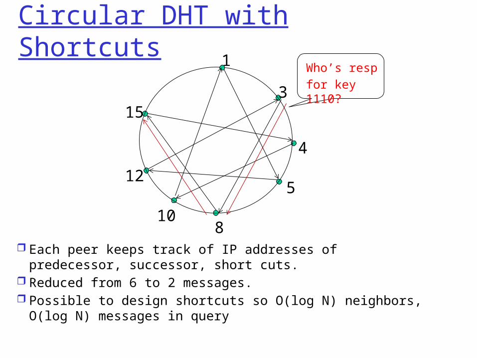
Circular DHT with Shortcuts
Each peer keeps track of IP addresses of predecessor, successor, short cuts.
Reduced from 6 to 2 messages. Possible to design shortcuts so O(log N) neighbors, O(log N)
messages in query
13
4
5
810
12
15
Who’s resp for key 1110?
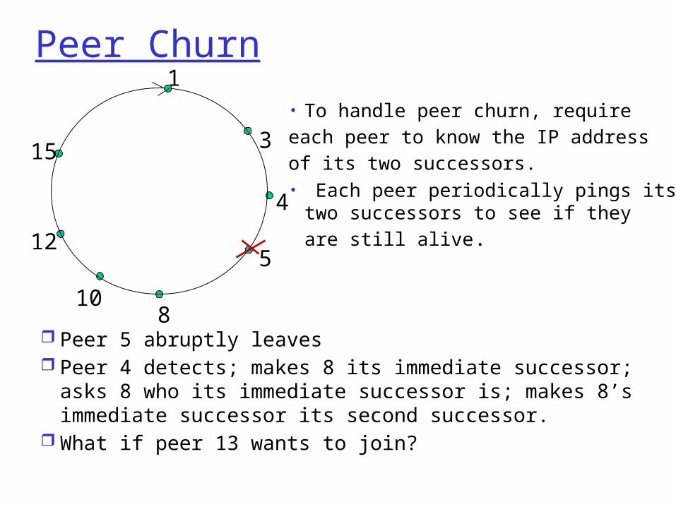
Peer Churn
Peer 5 abruptly leaves Peer 4 detects; makes 8 its immediate successor;
asks 8 who its immediate successor is; makes 8’s immediate successor its second successor.
What if peer 13 wants to join?
1
3
4
5
810
12
15• To handle peer churn, require each peer to know the IP address of its two successors. • Each peer periodically pings its
two successors to see if they are still alive.
2: Application Layer 93
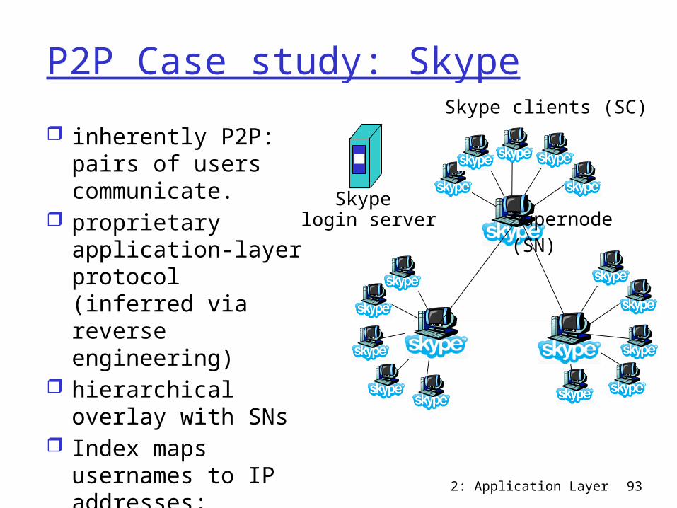
P2P Case study: Skype inherently P2P: pairs
of users communicate.
proprietary application-layer protocol (inferred via reverse engineering)
hierarchical overlay with SNs
Index maps usernames to IP addresses; distributed over SNs
Skype clients (SC)
Supernode (SN)
Skype login server
2: Application Layer 94
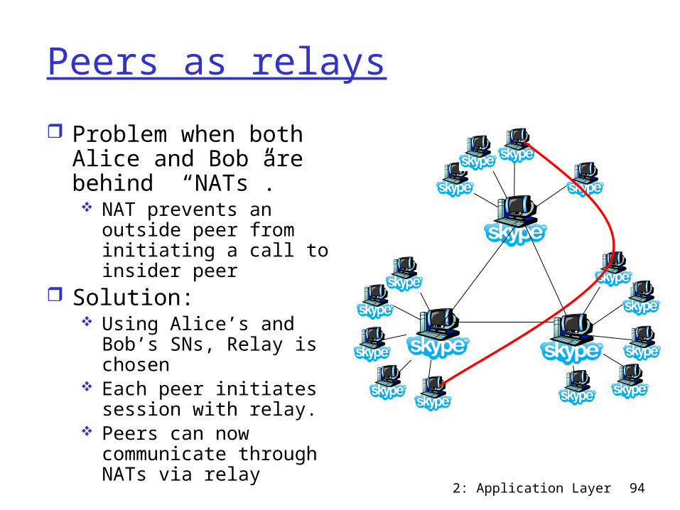
Peers as relays Problem when both
Alice and Bob are behind “NATs”. NAT prevents an
outside peer from initiating a call to insider peer
Solution: Using Alice’s and Bob’s
SNs, Relay is chosen Each peer initiates
session with relay. Peers can now
communicate through NATs via relay
2: Application Layer 95
Chapter 2: Application layer 2.1 Principles of network applications 2.2 Web and HTTP 2.3 FTP 2.4 Electronic Mail
SMTP, POP3, IMAP 2.5 DNS
2.6 P2P applications 2.7 Socket
programming with UDP
2.8 Socket programming with TCP
2: Application Layer 96
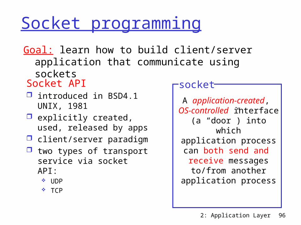
Socket programming
Socket API introduced in BSD4.1
UNIX, 1981 explicitly created, used,
released by apps client/server paradigm two types of transport
service via socket API: UDP TCP
A application-created, OS-controlled interface (a “door”) into which
application process can both send and
receive messages to/from another
application process
socket
Goal: learn how to build client/server application that communicate using sockets
Socket programming basics Server must be
running before client can send anything to it.
Server must have a socket (door) through which it receives and sends segments
Similarly client needs a socket
Socket is locally identified with a port number Analogous to the apt
# in a building Client needs to know
server IP address and socket port number.
2: Application Layer 97

2: Application Layer 98
Socket programming with UDP
UDP: no “connection” between client and server
no handshaking sender explicitly attaches
IP address and port of destination to each segment
OS attaches IP address and port of sending socket to each segment
Server can extract IP address, port of sender from received segment
application viewpointUDP provides unreliable transfer
of groups of bytes (“datagrams”) between client and server
Note: the official terminology for a UDP packet is “datagram”. In this class, we instead use “UDP segment”.
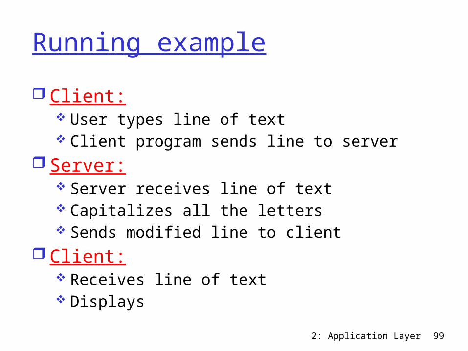
Running example Client:
User types line of text Client program sends line to server
Server: Server receives line of text Capitalizes all the letters Sends modified line to client
Client: Receives line of text Displays
2: Application Layer 99
2: Application Layer 100
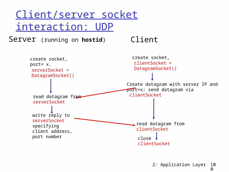
Client/server socket interaction: UDPServer (running on hostid)
closeclientSocket
read datagram fromclientSocket
create socket,clientSocket = DatagramSocket()
Client
Create datagram with server IP andport=x; send datagram via clientSocket
create socket,port= x.serverSocket = DatagramSocket()
read datagram fromserverSocket
write reply toserverSocketspecifying client address,port number
2: Application Layer 101
Example: Java client (UDP)
send
Pac
ket
to network from network
rece
iveP
acke
t
inFr
omU
ser
keyboard monitor
Process
clientSocket
UDPpacket
inputstream
UDPpacket
UDPsocket
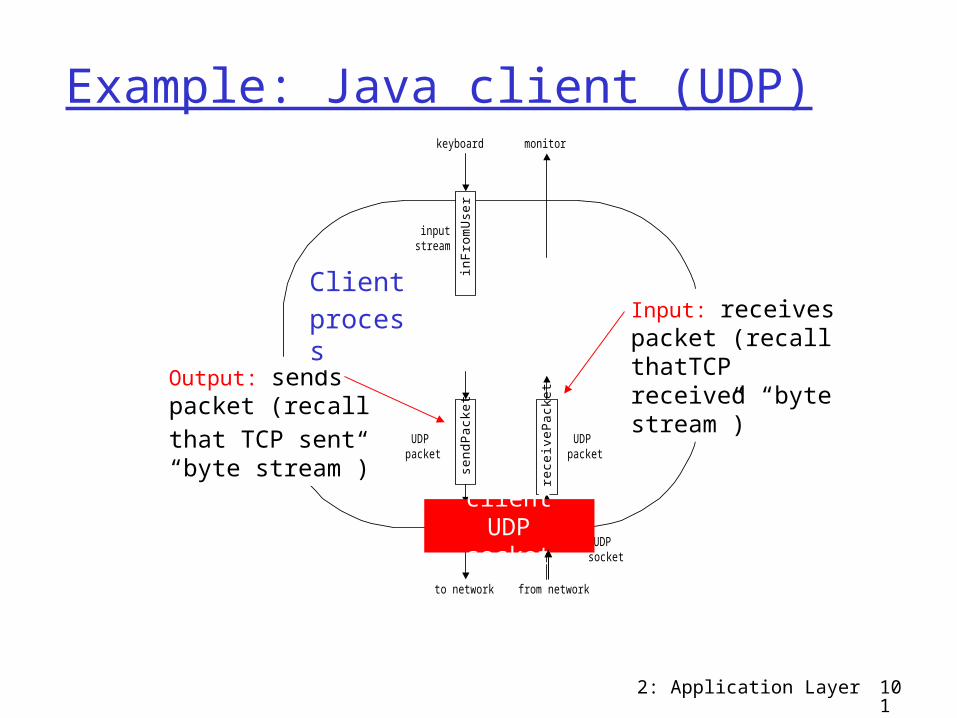
Output: sends packet (recallthat TCP sent “byte stream”)
Input: receives packet (recall thatTCP received “byte stream”)
Clientprocess
client UDP socket

2: Application Layer 102
Example: Java client (UDP)import java.io.*; import java.net.*; class UDPClient { public static void main(String args[]) throws Exception { BufferedReader inFromUser = new BufferedReader(new InputStreamReader(System.in)); DatagramSocket clientSocket = new DatagramSocket(); InetAddress IPAddress = InetAddress.getByName("hostname"); byte[] sendData = new byte[1024]; byte[] receiveData = new byte[1024]; String sentence = inFromUser.readLine();
sendData = sentence.getBytes();
Createinput stream
Create client socket
Translate hostname to IP
address using DNS
2: Application Layer 103
Example: Java client (UDP), cont.
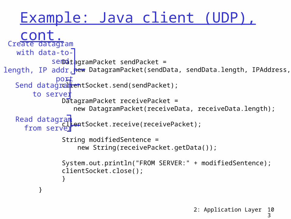
DatagramPacket sendPacket = new DatagramPacket(sendData, sendData.length, IPAddress, 9876); clientSocket.send(sendPacket); DatagramPacket receivePacket = new DatagramPacket(receiveData, receiveData.length); clientSocket.receive(receivePacket); String modifiedSentence = new String(receivePacket.getData()); System.out.println("FROM SERVER:" + modifiedSentence); clientSocket.close(); }
}
Create datagram with data-to-send,
length, IP addr, port
Send datagramto server
Read datagramfrom server
2: Application Layer 104
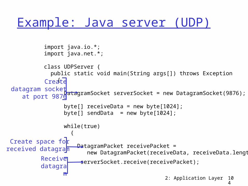
Example: Java server (UDP)import java.io.*; import java.net.*; class UDPServer { public static void main(String args[]) throws Exception { DatagramSocket serverSocket = new DatagramSocket(9876); byte[] receiveData = new byte[1024]; byte[] sendData = new byte[1024]; while(true) { DatagramPacket receivePacket = new DatagramPacket(receiveData, receiveData.length);
serverSocket.receive(receivePacket);
Createdatagram socket
at port 9876
Create space forreceived datagram
Receivedatagra
m
2: Application Layer 105
Example: Java server (UDP), cont
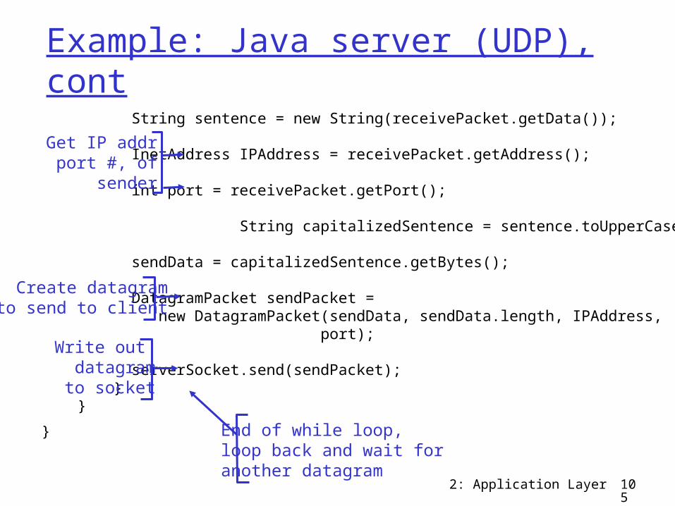
String sentence = new String(receivePacket.getData()); InetAddress IPAddress = receivePacket.getAddress(); int port = receivePacket.getPort(); String capitalizedSentence = sentence.toUpperCase();
sendData = capitalizedSentence.getBytes(); DatagramPacket sendPacket = new DatagramPacket(sendData, sendData.length, IPAddress, port); serverSocket.send(sendPacket); } }
}
Get IP addrport #, of
sender
Write out datagramto socket
End of while loop,loop back and wait foranother datagram
Create datagramto send to client
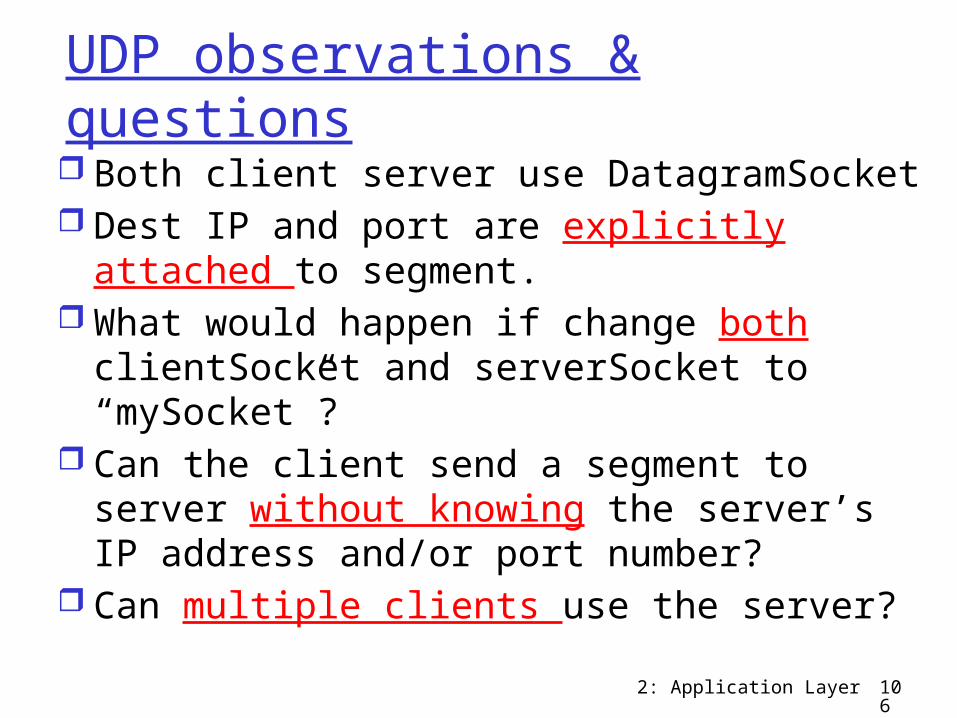
UDP observations & questions Both client server use DatagramSocket Dest IP and port are explicitly attached to
segment. What would happen if change both
clientSocket and serverSocket to “mySocket”?
Can the client send a segment to server without knowing the server’s IP address and/or port number?
Can multiple clients use the server?2: Application Layer 106
2: Application Layer 107
Chapter 2: Application layer 2.1 Principles of network applications 2.2 Web and HTTP 2.3 FTP 2.4 Electronic Mail
SMTP, POP3, IMAP 2.5 DNS
2.6 P2P applications 2.7 Socket
programming with UDP
2.8 Socket programming with TCP
2: Application Layer 108
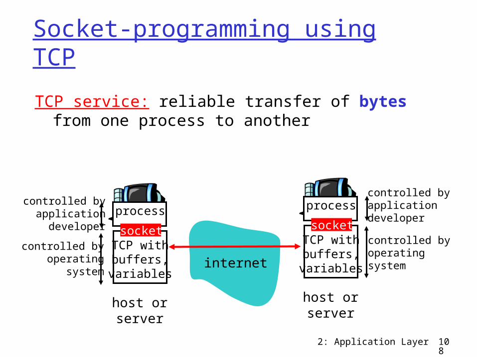
Socket-programming using TCP
TCP service: reliable transfer of bytes from one process to another
process
TCP withbuffers,
variables
socket
controlled byapplicationdeveloper
controlled byoperating
system
host orserver
process
TCP withbuffers,
variables
socket
controlled byapplicationdevelopercontrolled byoperatingsystem
host orserver
internet
2: Application Layer 109
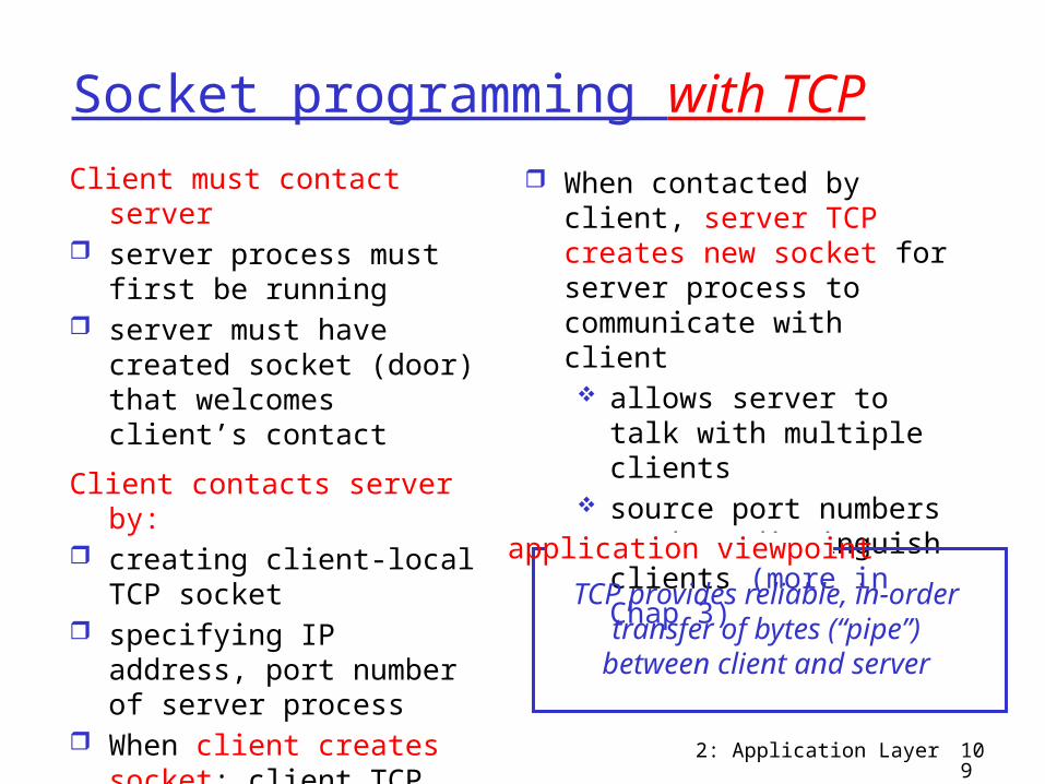
Socket programming with TCPClient must contact server server process must first
be running server must have
created socket (door) that welcomes client’s contact
Client contacts server by: creating client-local TCP
socket specifying IP address,
port number of server process
When client creates socket: client TCP establishes connection to server TCP
When contacted by client, server TCP creates new socket for server process to communicate with client allows server to talk
with multiple clients source port numbers
used to distinguish clients (more in Chap 3)
TCP provides reliable, in-order transfer of bytes (“pipe”) between client and server
application viewpoint
2: Application Layer 110
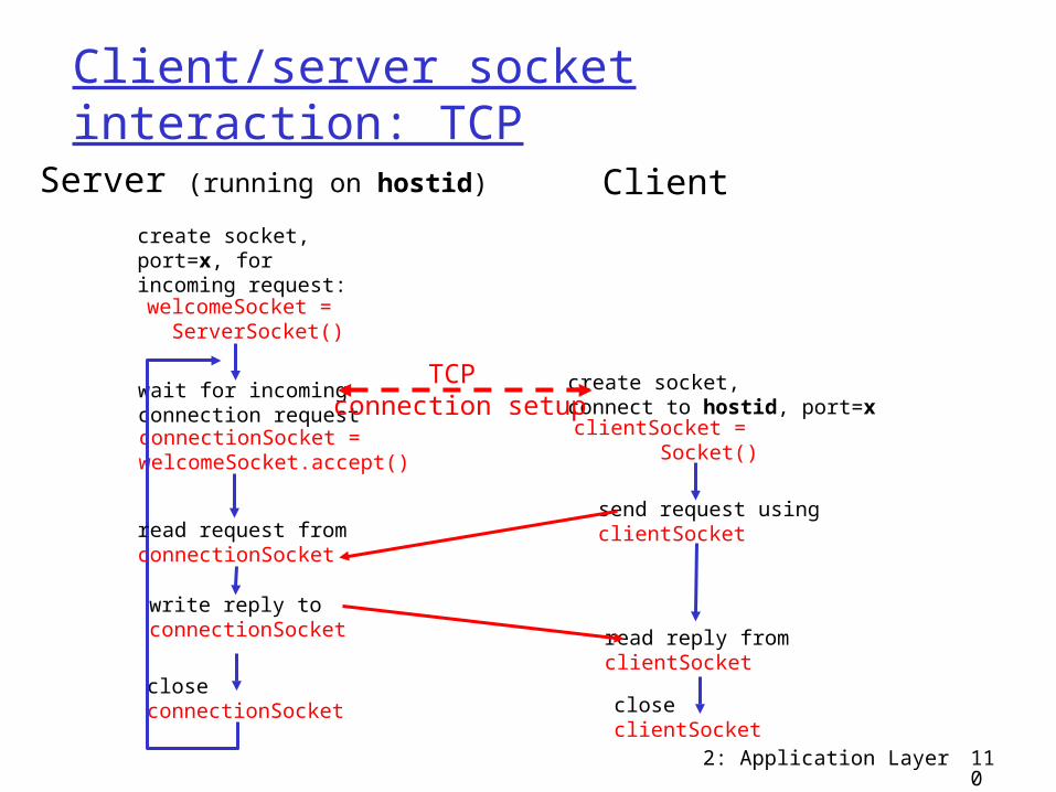
Client/server socket interaction: TCP
wait for incomingconnection requestconnectionSocket =welcomeSocket.accept()
create socket,port=x, forincoming request:welcomeSocket =
ServerSocket()
create socket,connect to hostid, port=xclientSocket =
Socket()
closeconnectionSocket
read reply fromclientSocket
closeclientSocket
Server (running on hostid) Client
send request usingclientSocketread request from
connectionSocket
write reply toconnectionSocket
TCP connection setup
2: Application Layer 111ou
tToS
erve
r
to network from network
inFr
omS
erve
r
inFr
omU
ser
keyboard monitor
Process
clientSocket
inputstream
inputstream
outputstream
TCPsocket
Clientprocess
client TCP socket
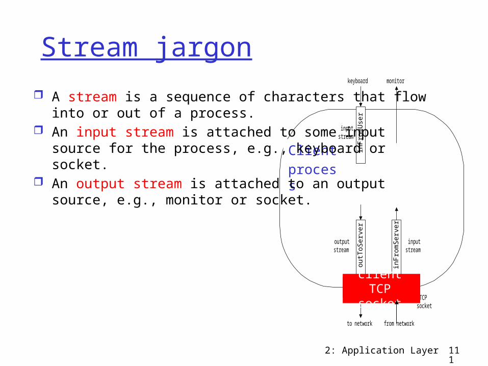
Stream jargon A stream is a sequence of characters that flow into or
out of a process. An input stream is attached to some input source for the
process, e.g., keyboard or socket. An output stream is attached to an output source, e.g.,
monitor or socket.
2: Application Layer 112
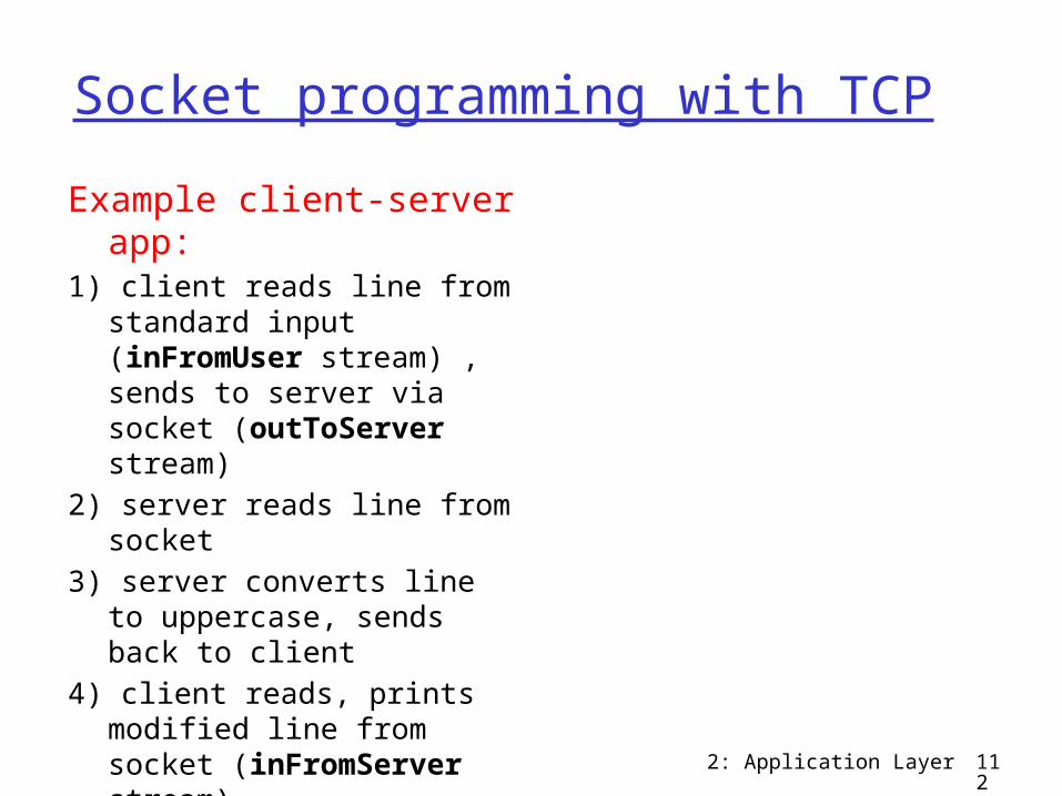
Socket programming with TCPExample client-server
app:1) client reads line from
standard input (inFromUser stream) , sends to server via socket (outToServer stream)
2) server reads line from socket
3) server converts line to uppercase, sends back to client
4) client reads, prints modified line from socket (inFromServer stream)
2: Application Layer 113
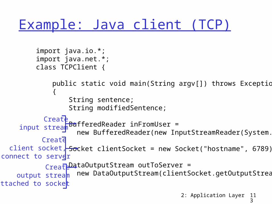
Example: Java client (TCP)import java.io.*; import java.net.*; class TCPClient {
public static void main(String argv[]) throws Exception { String sentence; String modifiedSentence;
BufferedReader inFromUser = new BufferedReader(new InputStreamReader(System.in));
Socket clientSocket = new Socket("hostname", 6789);
DataOutputStream outToServer = new DataOutputStream(clientSocket.getOutputStream());
Createinput stream
Create client socket,
connect to serverCreate
output streamattached to socket
2: Application Layer 114
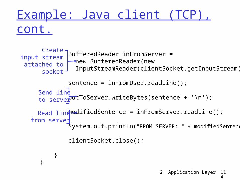
Example: Java client (TCP), cont.
BufferedReader inFromServer = new BufferedReader(new InputStreamReader(clientSocket.getInputStream()));
sentence = inFromUser.readLine();
outToServer.writeBytes(sentence + '\n');
modifiedSentence = inFromServer.readLine();
System.out.println("FROM SERVER: " + modifiedSentence);
clientSocket.close(); } }
Createinput stream
attached to socket
Send lineto server
Read linefrom server
2: Application Layer 115
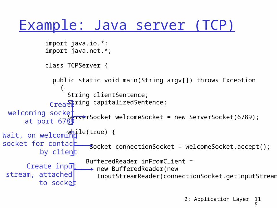
Example: Java server (TCP)import java.io.*; import java.net.*;
class TCPServer {
public static void main(String argv[]) throws Exception { String clientSentence; String capitalizedSentence;
ServerSocket welcomeSocket = new ServerSocket(6789); while(true) { Socket connectionSocket = welcomeSocket.accept();
BufferedReader inFromClient = new BufferedReader(new InputStreamReader(connectionSocket.getInputStream()));
Createwelcoming socket
at port 6789Wait, on welcoming
socket for contactby client
Create inputstream, attached
to socket
2: Application Layer 116
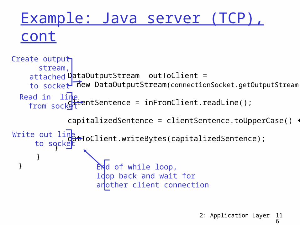
Example: Java server (TCP), cont
DataOutputStream outToClient = new DataOutputStream(connectionSocket.getOutputStream());
clientSentence = inFromClient.readLine();
capitalizedSentence = clientSentence.toUpperCase() + '\n';
outToClient.writeBytes(capitalizedSentence); } } }
Read in linefrom socket
Create outputstream,
attached to socket
Write out lineto socket
End of while loop,loop back and wait foranother client connection
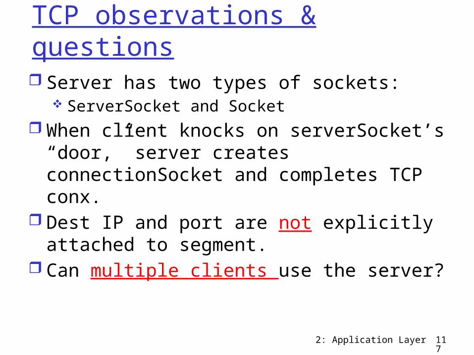
TCP observations & questions Server has two types of sockets:
ServerSocket and Socket When client knocks on serverSocket’s
“door,” server creates connectionSocket and completes TCP conx.
Dest IP and port are not explicitly attached to segment.
Can multiple clients use the server?
2: Application Layer 117
2: Application Layer 118
Chapter 2: Summary
application architectures client-server P2P hybrid
application service requirements: reliability, bandwidth,
delay Internet transport
service model connection-oriented,
reliable: TCP unreliable, datagrams:
UDP
our study of network apps now complete! specific protocols:
HTTP FTP SMTP, POP, IMAP DNS P2P: BitTorrent, Skype
socket programming
2: Application Layer 119
Chapter 2: Summary
typical request/reply message exchange: client requests info or
service server responds with
data, status code message formats:
headers: fields giving info about data
data: info being communicated
Most importantly: learned about protocols
Important themes: control vs. data msgs
in-band, out-of-band
centralized vs. decentralized
stateless vs. stateful reliable vs. unreliable
msg transfer “complexity at
network edge”
Top Related
