


![Negative Refractive Index in Hydrodynamical SystemsNote that in [3] it was already argued that negative refraction is an ubiquitous phe-nomenon in hydrodynamical charged systems, supporting](https://static.fdocuments.in/doc/165x107/5e3d68c5d7c54a0ac77a6533/negative-refractive-index-in-hydrodynamical-systems-note-that-in-3-it-was-already.jpg)

Languages
Pages
Legal


Negative Index of Refraction
By: Jason KaszpurenkoJournal Club1/16/09
Overview
Both articles that I read were from a Materials Research Society October 2008 Bulletin
General Overview about negative index materials: What is ti What properties does it have What possible applications
Making Negative Index of Refraction materials Two types of Negative Index Materials Attempts to get into the optical range
Questions (Yours and mine)
Overview
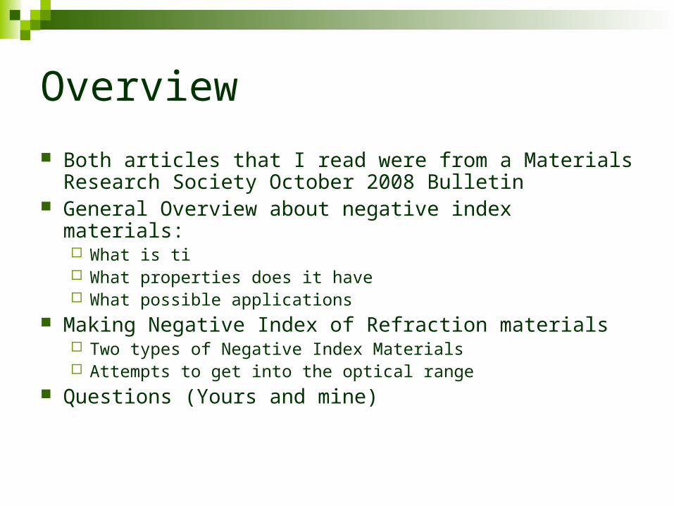
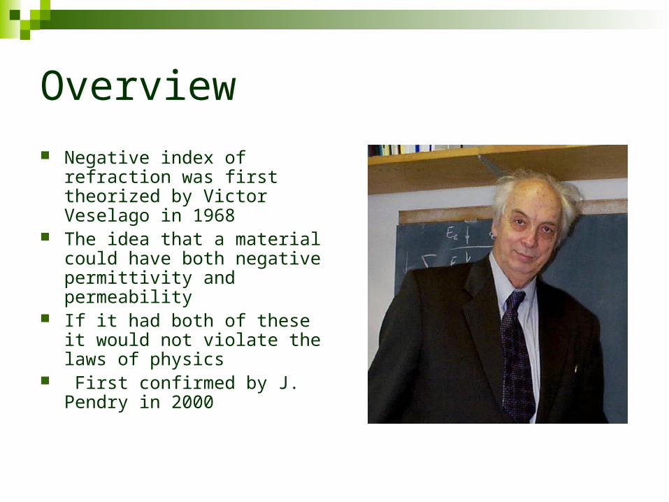
Negative index of refraction was first theorized by Victor Veselago in 1968
The idea that a material could have both negative permittivity and permeability
If it had both of these it would not violate the laws of physics
First confirmed by J. Pendry in 2000

Overview
Index of refraction is normally defined by n=c/v or n=(εμ)^0.5 c is the speed of light in vacuum, v is the speed of
light in a medium, ε is permittivity and μ is permeability
ε can be found negative naturally in several metals such as gold and silver but μ needs to be engineered artificially to be negative
The shortest wavelength observed with this property is 710 nm

Overview In a normal material the k, E and H
of the material right handed set (good old right hand rule)
In negative index materials (NIM) the k, E and H form a left handed set (your students were doing it for negative index of materials)
This causes the wave’s phase front to move in the opposite direction of the wave itself
The energy of the wave is associated with the group velocity
To the right we have an example of this. The Gaussian wave packet moves to the right while the wave front, (red point) moves to the left
W. Park, J. Kim, MRS bulletin Oct 2008

Optical Properties of negative index materials Negative index materials can be used to
make:Electromagnetic cloaking devicesSuper lenses filtersSub wavelength waveguides and antennas
I’m going to talk about the super lenses

Super lenses
In most optics the limiting factor is the wavelength of light
The evanescent waves, waves which exponentially decay in mater, actually contain information that is smaller than the wavelength, but this is normally lost
In negative index materials the evanescent waves are actually enhanced
Evanescent waves
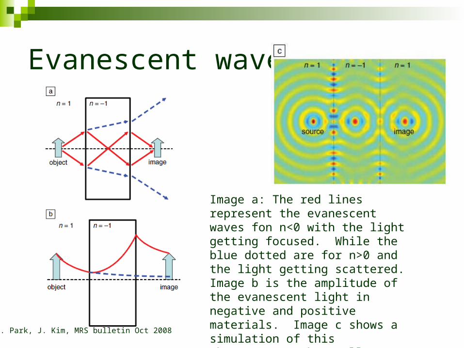
Image a: The red lines represent the evanescent waves fon n<0 with the light getting focused. While the blue dotted are for n>0 and the light getting scattered. Image b is the amplitude of the evanescent light in negative and positive materials. Image c shows a simulation of this phenomenon. The smaller image than source size means enhanced evanescent waves.
W. Park, J. Kim, MRS bulletin Oct 2008

Elaboration of conditions needed for negative index materials Originally Veselago argued that you need the real and
complex parts of permeability and permittivity to be negative
This is an over constrained condition the real one is: ε’μ”+ ε”μ’<0 (’ is real and ” is complex part)
If ε’<0 or μ’<0 we have a single-negative NIM (SN-NIM) If ε’<0 and μ’<0 we have a double-negative NIM (DN-
NIM), DN-NIM have the potential to have less losses and are considered better because of this
Making μ < 0
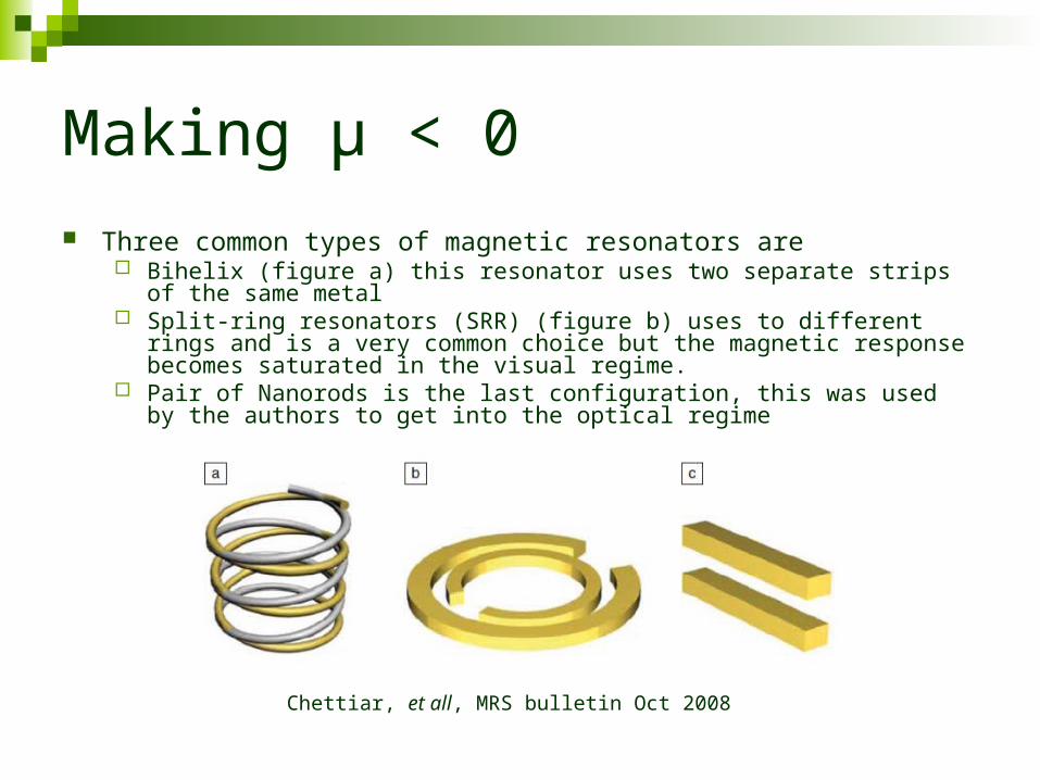
Three common types of magnetic resonators are Bihelix (figure a) this resonator uses two separate strips of the same metal Split-ring resonators (SRR) (figure b) uses to different rings and is a very
common choice but the magnetic response becomes saturated in the visual regime.
Pair of Nanorods is the last configuration, this was used by the authors to get into the optical regime
Chettiar, et all, MRS bulletin Oct 2008

Synthesis
An attempt was made to synthesize nanorods with different deposition rates Al2O3 was deposited in
between the layers Ag nanorods
Sample A was deposited at 2 A/s while sample B was deposited at 0.5 A/s
Using AFM cross sections we can see that the faster deposition rate created (right) a rougher surface than the slower deposition (lower right)
Chettiar, et all, MRS bulletin Oct 2008

Permittivity and Permeability
Chettiar, et all, MRS bulletin Oct 2008
Sample A has a high deposition rate and Sample B has a low deposition rate
Results for different spacing
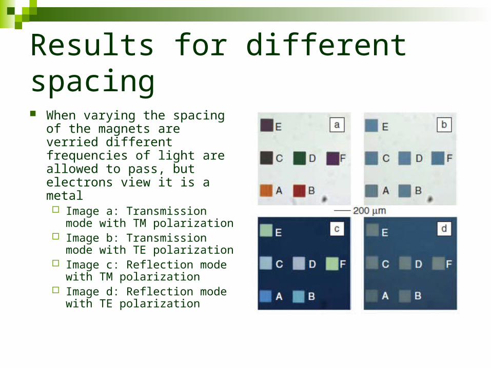
When varying the spacing of the magnets are verried different frequencies of light are allowed to pass, but electrons view it is a metal Image a: Transmission mode
with TM polarization Image b: Transmission mode
with TE polarization Image c: Reflection mode with
TM polarization Image d: Reflection mode with
TE polarization

Conclusion
Although theorized over 40 years ago NIM have only been made within the last decade
NIM act in many unconventional ways, wave phase front moves in opposite direction of group velocity, evanescent waves increase….
These properties lend themselves to making unique devices like super lenses that can overcome traditional optical limits
The difficulty in making them comes from the negative permeability, which has to be artificially manufactured
The optical regime is just being realized

Questions
How does varying the oxide material in-between the nanorods effect the index of refraction
With evanescent waves increasing in amplitude, how is energy being conserved?
What attempts have there been on working on different materials with a negative permittivity
Top Related