


Languages
Pages
Legal


Navistar Confidential Proprietary
DR100159-05 Electronic Module and/or System Environmental Performance
Page 1 of 49 Release date: 15 August 2013
Design Requirement Document
Document No. DR100159-05
Engineering Program No. 748
Department No. 385395
System EE Module
Subsystem Modules and Components
Description Electronic Module and/or System Environmental Performance
Navistar Confidential Proprietary
DR100159-05 Electronic Module and/or System Environmental Performance
Page 2 of 49 Release date: 15 August 2013
Table of Contents
1. Revision Summary Table....................................................................................................................................... 4
2. Scope
2.1. Purpose ............................................................................................................................................................. 14 2.2. Description ......................................................................................................................................................... 14
3. Applicable Documents .......................................................................................................................................... 15
3.1. Industry Standards ............................................................................................................................................. 15 3.2. Navistar Documents ........................................................................................................................................... 15
4. Definitions and Nomenclature............................................................................................................................... 16
4.1. Functional Test .................................................................................................................................................. 16 4.2. Parametric Test ................................................................................................................................................. 16 4.3. Functional Class ................................................................................................................................................ 16 4.4. Status of Performance ....................................................................................................................................... 16 4.5. Nomenclature .................................................................................................................................................... 17
5. Climatic Environment ............................................................................................................................................ 18
5.1. Operational Temperature ................................................................................................................................... 18 5.2. Three Temperature Parametric Test .................................................................................................................. 18 5.3. Storage Temperature Test ................................................................................................................................. 18 5.4. Thermal Cycle Test ............................................................................................................................................ 19 5.5. Thermal Shock Test ........................................................................................................................................... 19
5.5.1. Thermal Shock Test (Short) ......................................................................................................................... 19 5.5.2. Thermal Shock Test (Long) .......................................................................................................................... 20
5.6. Humidity Test ..................................................................................................................................................... 21 5.6.1. Humidity Test (Short) ................................................................................................................................... 21 5.6.2. Humidity Test (Long).................................................................................................................................... 21
5.7. Frost Test .......................................................................................................................................................... 22 5.8. Salt Spray Test .................................................................................................................................................. 22 5.9. Immersion Test .................................................................................................................................................. 22 5.10. Exposure to Chemicals and Oils ...................................................................................................................... 23 5.11. Steam Cleaning and Pressure Washing ........................................................................................................... 24
5.11.1. Pressure Washing ..................................................................................................................................... 24 5.11.2. Steam Cleaning ......................................................................................................................................... 24
5.12. Fungus............................................................................................................................................................. 25 5.13. Altitude............................................................................................................................................................. 25
5.13.1. Altitude (Operating) .................................................................................................................................... 25 5.13.2. Altitude (Non-Operating) ............................................................................................................................ 25
6. Mechanical Environment ....................................................................................................................................... 26
6.1. Dust and Sand ................................................................................................................................................... 26 6.2. Gravel Bombardment ......................................................................................................................................... 26 6.3. Combined Environmental Testing ...................................................................................................................... 26 6.4. Swept Sine Vibration Test .................................................................................................................................. 27 6.5. Random Vibration Testing .................................................................................................................................. 27 6.6. Handling Drop Test ............................................................................................................................................ 28 6.7. Transit Drop Test ............................................................................................................................................... 28 6.8. Installation Harness Shock Test ......................................................................................................................... 29 6.9. Operational Shock ............................................................................................................................................. 29
7. Electrical Environment .......................................................................................................................................... 30
7.1. Operational Voltage ........................................................................................................................................... 30 7.2. Jump Starting..................................................................................................................................................... 30 7.3. Cold Cranking .................................................................................................................................................... 31 7.4. Reverse Polarity ................................................................................................................................................ 32 7.5. Voltage Regulator Failure .................................................................................................................................. 32 7.6. Open Circuit ....................................................................................................................................................... 33 7.7. Short Circuit ....................................................................................................................................................... 33 7.8. Operation without Batteries ................................................................................................................................ 33 7.9. Conducted Transients ........................................................................................................................................ 34
7.9.1. Inductive Switching - Pulse 1 ....................................................................................................................... 34 7.9.2. Inductive Switching - Pulse 2a ..................................................................................................................... 34 7.9.3. Inductive Switching - Pulse 2b ..................................................................................................................... 35

Navistar Confidential Proprietary
DR100159-05 Electronic Module and/or System Environmental Performance
Page 3 of 49 Release date: 15 August 2013
7.9.4. Switching Spikes - Pulse 3a ......................................................................................................................... 35 7.9.5. Switching Spikes - Pulse 3b ......................................................................................................................... 36 7.9.6. Load Dump - Pulse 5a ................................................................................................................................. 37 7.9.7. Low Side Outputs Bias by Ignition or Accessory .......................................................................................... 37
7.10. Coupled Transients .......................................................................................................................................... 37 7.10.1. Capacitive Coupling Clamp ........................................................................................................................ 37 7.10.2. Chattering Relay ........................................................................................................................................ 38
7.11. Electrostatic Discharge .................................................................................................................................... 39 7.11.1. Electrostatic Discharge (Unpowered) ......................................................................................................... 39 7.11.2. Electrostatic Discharge (Powered) ............................................................................................................. 39
7.12. Conducted Emissions ...................................................................................................................................... 40 7.13. Radiated Emissions ......................................................................................................................................... 40 7.14. Radiated Immunity ........................................................................................................................................... 41 7.15. Bulk Current Injection ....................................................................................................................................... 42
8. Vehicle Level .......................................................................................................................................................... 44
8.1. Electrostatic Discharge ...................................................................................................................................... 44 8.2. Radiated Emissions ........................................................................................................................................... 44 8.3. Radiated Susceptibility - Off Vehicle Source ...................................................................................................... 45 8.4. SINAD Test ........................................................................................................................................................ 46
9. Test Flow ................................................................................................................................................................ 47
9.1. Test Flow with Combined Environmental Testing ............................................................................................... 48
10. Reliability Life Test .............................................................................................................................................. 49

Navistar Confidential Proprietary
DR100159-05 Electronic Module and/or System Environmental Performance
Page 4 of 49 Release date: 15 August 2013
1. Revision Summary Table
Revised By Revision Section Description Reason Date
U00HEK2 00
Initial release. Formerly EEF-R1-020 Revision 6. No technical changes,
includes formatting corrections.
19 May 2006
U00HRW2 01 2
Updated the dates for the SAE Document J1455 AUG94 to
JUNE2006 and J551-1 JUN96 to OCT2006.
New updates from SAE.
24 Nov. 2008
U00HRW2 01 2 SAE Cancelled J1113-41 and replaced it with
CISPR25.
SAE Cancelled J1113-41.
24 Nov. 2008
U00HRW2 01 2 Added SAE J1113-21
for EMI SAE recommended. 24 Nov. 2008
U00HRW2 01 4.1.3.2 Added Salt Immersion Testing Section 4.1.3.2
New test from SAE. 24 Nov. 2008
U00HRW2 01 3.2 Replaced Region with
Status functions. New SAE
nomenclature. 24 Nov. 2008
U00HRW2 01 3
Moved the module Classifications and Status from the EMI
Section to their definition section.
Other tests now use the module
Classification and status functions.
24 Nov. 2008
U00HRW2 01 3.1, 3.2, 3.3, 3.4
Removed sections 3.1 Features and Functions,
3.2 Performance, 3.3 Physical, 3.4 Electrical.
This in the product specifications.
24 Nov. 2008
U00HRW2 01 Was
3.5.1.4
Removed Thermal stress (Reliability Demonstration)
This will go in the new Reliability DRD.
24 Nov. 2008
U00HRW2 01
4.1.13.8.1,
4.1.13.8.2
Added Test Severity Level 4 to the
Conducted and Coupled Transients Section.
New SAE test severity levels.
24 Nov. 2008
U00HRW2 01 4.2.1, 4.2.2
Added in cab and Chassis DV and PV test
flow chart.
Recommended by the department.
24 Nov. 2008
U00HRW2 01 4.1.14.1
.3.2 Added BCI Component Test per SAE 1113-4
SAE Recommended. 24 Nov. 2008
U00HRW2 01 Was
3.5.11.8 Ultraviolet Resistance
was removed This will be in the
product specifications. 24 Nov. 2008
Navistar Confidential Proprietary
DR100159-05 Electronic Module and/or System Environmental Performance
Page 5 of 49 Release date: 15 August 2013
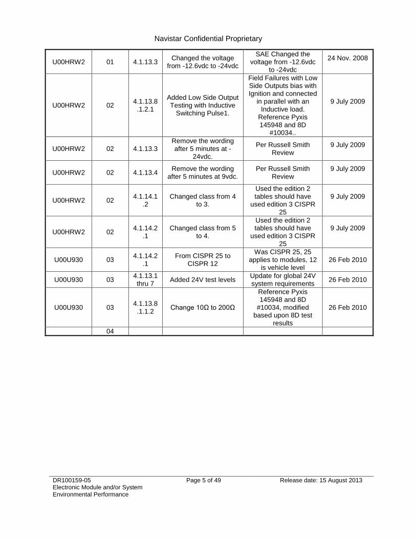
U00HRW2 01 4.1.13.3 Changed the voltage
from -12.6vdc to -24vdc
SAE Changed the voltage from -12.6vdc
to -24vdc
24 Nov. 2008
U00HRW2 02 4.1.13.8.1.2.1
Added Low Side Output Testing with Inductive
Switching Pulse1.
Field Failures with Low Side Outputs bias with Ignition and connected
in parallel with an Inductive load.
Reference Pyxis 145948 and 8D
#10034..
9 July 2009
U00HRW2 02 4.1.13.3 Remove the wording after 5 minutes at -
24vdc.
Per Russell Smith Review
9 July 2009
U00HRW2 02 4.1.13.4 Remove the wording
after 5 minutes at 9vdc. Per Russell Smith
Review 9 July 2009
U00HRW2 02 4.1.14.1
.2 Changed class from 4
to 3.
Used the edition 2 tables should have
used edition 3 CISPR 25
9 July 2009
U00HRW2 02 4.1.14.2
.1 Changed class from 5
to 4.
Used the edition 2 tables should have
used edition 3 CISPR 25
9 July 2009
U00U930 03 4.1.14.2
.1 From CISPR 25 to
CISPR 12
Was CISPR 25, 25 applies to modules, 12
is vehicle level 26 Feb 2010
U00U930 03 4.1.13.1 thru 7
Added 24V test levels Update for global 24V system requirements
26 Feb 2010
U00U930 03 4.1.13.8.1.1.2
Change 10Ω to 200Ω
Reference Pyxis 145948 and 8D
#10034, modified based upon 8D test
results
26 Feb 2010
04

Navistar Confidential Proprietary
DR100159-05 Electronic Module and/or System Environmental Performance
Page 6 of 49 Release date: 15 August 2013
U023768 05
Was 4, 4.1,
4.1.2, 4.1.3, 4.1.10,
4.1.10.3, 4.1.11, 4.1.13.2
.1, 4.1.13.2
.2, 4.1.14,
4.1.14.1,
4.1.14.1.3,
4.1.14.2, 4.2,
4.1.14.2.2.1
Sections Removed
These sections were redundant when moved into the new document
format
11 Jan 2013
U023768 05 2 Used to be Section 1 Formatting change 11 Jan 2013
U023768 05 3 Used to be Section 2 Formatting change 11 Jan 2013
U023768 05 3.1, 3.2 Included latest Industry Standards and Navistar
Documents 11 Jan 2013
U023768 05 4.1 Included Functional
Test Definition Definition of procedure to be followed after test
11 Jan 2013
U023768 05 4.2 Included Parametric
Test Definition Definition of procedure to be followed after test
11 Jan 2013
U023768 05 4.3 Used to be Section 3.2 Formatting change 11 Jan 2013
U023768 05 4.4 Used to be Section 3.3 Formatting change 11 Jan 2013
U023768 05 4.5 Included table of
nomenclature 11 Jan 2013
U023768 05 5 Created for all
Environmental Tests Formatting change 11 Jan 2013
U023768 05 5.1
Used to be Section 4.1.1
Added specific
temperature ranges for various mounting
locations
To reduce confusion amongst Engineers
and Suppliers 11 Jan 2013
U023768 05 5.2 Included new requirement
Test sequence to be used as indicated in the
test flow chart 11 Jan 2013
U023768 05 5.3
Used to be Section 4.1.1.1
Added specific
temperature ranges
To reduce confusion amongst Engineers
and Suppliers 11 Jan 2013

Navistar Confidential Proprietary
DR100159-05 Electronic Module and/or System Environmental Performance
Page 7 of 49 Release date: 15 August 2013
U023768 05 5.4
Used to be Section 4.1.1.2
Added specific test flow and parameters along
with a new figure
To reduce confusion amongst Engineers
and Suppliers 11 Jan 2013
U023768 05 5.5.1
Used to be Section 4.1.1.3
Added specific test flow and parameters along
with a new figure
To reduce confusion amongst Engineers
and Suppliers 11 Jan 2013
U023768 05 5.5.2 Included new requirement
This test will demonstrate long term
reliability 11 Jan 2013
U023768 05 5.6.1
Used to be Section 4.1.2.1
Added specific test flow and parameters along
with a new figure
To reduce confusion amongst Engineers
and Suppliers 11 Jan 2013
U023768 05 5.6.2 Included new requirement
This test will demonstrate long term
reliability 11 Jan 2013
U023768 05 5.6.3
Used to be Section 4.1.2.2
Included statement
indicating frost condition may be introduced
during Humidity testing
To reduce confusion amongst Engineers
and Suppliers 11 Jan 2013
U023768 05 5.7
Used to be Section 4.1.3.1
Added specific test
parameters.
To reduce confusion amongst Engineers
and Suppliers 11 Jan 2013
U023768 05 5.8
Used to be Section 4.1.3.2
Added specific test
parameters.
To reduce confusion amongst Engineers
and Suppliers 11 Jan 2013
U023768 05 5.9
Used to be Section 4.1.4
Added specific test
parameters and table of chemicals.
To reduce confusion amongst Engineers
and Suppliers 11 Jan 2013
U023768 05 5.10.1
Used to be Section 4.1.5
Added specific test
parameters.
To reduce confusion amongst Engineers
and Suppliers 11 Jan 2013

Navistar Confidential Proprietary
DR100159-05 Electronic Module and/or System Environmental Performance
Page 8 of 49 Release date: 15 August 2013
U023768 05 5.10.2
Used to be Section 4.1.5
Added specific test
parameters. Separated from 5.10 to reduce
confusion.
To reduce confusion amongst Engineers
and Suppliers 11 Jan 2013
U023768 05 5.11
Used to be Section 4.1.6
Added specific test
parameters.
To reduce confusion amongst Engineers
and Suppliers 11 Jan 2013
U023768 05 5.12.1
Used to be Section 4.1.9
Added specific test
parameters.
To reduce confusion amongst Engineers
and Suppliers 11 Jan 2013
U023768 05 5.12.2
Used to be Section 4.1.9
Added specific test
parameters. Separated from 5.12 to reduce
confusion.
To reduce confusion amongst Engineers
and Suppliers 11 Jan 2013
U023768 05 6 Created for all
Mechanical Tests Formatting change 11 Jan 2013
U023768 05 6.1
Used to be Section 4.1.7
Added specific test
parameters.
To reduce confusion amongst Engineers
and Suppliers 11 Jan 2013
U023768 05 6.2
Used to be Section 4.1.8
Added specific test
parameters.
To reduce confusion amongst Engineers
and Suppliers 11 Jan 2013
U023768 05 6.3
Used to be Section 4.1.12
Added specific test
parameters.
To reduce confusion amongst Engineers
and Suppliers 11 Jan 2013
U023768 05 6.4
Used to be Section 4.1.10.1
Added specific test
parameters.
To reduce confusion amongst Engineers
and Suppliers 11 Jan 2013
U023768 05 6.5
Used to be Section 4.1.10.2
Added specific test
parameters.
To reduce confusion amongst Engineers
and Suppliers 11 Jan 2013
Navistar Confidential Proprietary
DR100159-05 Electronic Module and/or System Environmental Performance
Page 9 of 49 Release date: 15 August 2013
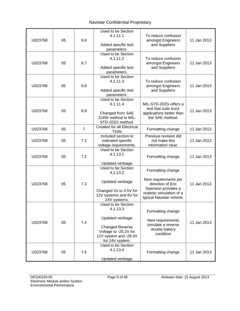
U023768 05 6.6
Used to be Section 4.1.11.1
Added specific test
parameters.
To reduce confusion amongst Engineers
and Suppliers 11 Jan 2013
U023768 05 6.7
Used to be Section 4.1.11.2
Added specific test
parameters.
To reduce confusion amongst Engineers
and Suppliers 11 Jan 2013
U023768 05 6.8
Used to be Section 4.1.11.3
Added specific test
parameters.
To reduce confusion amongst Engineers
and Suppliers 11 Jan 2013
U023768 05 6.9
Used to be Section 4.1.11.4
Changed from SAE
J1455 method to MIL-STD-202G method.
MIL-STD-202G offers a test that suits truck
applications better than the SAE method.
11 Jan 2013
U023768 05 7 Created for all Electrical
Tests Formatting change 11 Jan 2013
U023768 05 7.1 Included section to indicated specific
voltage requirements.
Previous revision did not make this
information clear. 11 Jan 2013
U023768 05 7.2
Used to be Section 4.1.13.1
Updated verbiage
Formatting change 11 Jan 2013
U023768 05 7.3
Used to be Section 4.1.13.2
Updated verbiage
Changed Vs to 4.5V for 12V systems and 6V for
24V systems.
Formatting change
New requirements per direction of Eric
Swenson provides a realistic simulation of a typical Navistar vehicle.
11 Jan 2013
U023768 05 7.4
Used to be Section 4.1.13.3
Updated verbiage
Changed Reverse
Voltage to -25.2V for 12V system and -28.4V
for 24V system.
Formatting change
New requirements simulate a reverse
double battery condition
11 Jan 2013
U023768 05 7.5
Used to be Section 4.1.13.4
Updated verbiage
Formatting change 11 Jan 2013

Navistar Confidential Proprietary
DR100159-05 Electronic Module and/or System Environmental Performance
Page 10 of 49 Release date: 15 August 2013
U023768 05 7.6
Used to be Section 4.1.13.5
Updated verbiage
Formatting change 11 Jan 2013
U023768 05 7.7
Used to be Section 4.1.13.6
Updated verbiage
Formatting change
Included new requirement to test at
max temp and min voltage
11 Jan 2013
U023768 05 7.8
Used to be Section 4.1.13.7
Updated verbiage
Formatting change 11 Jan 2013
U023768 05 7.9 Used to be Section
4.1.13.8.1 Formatting change 11 Jan 2013
U023768 05 7.9.1
Used to be Section 4.1.13.8.1.1.1
Added specific test
parameters.
To reduce confusion amongst Engineers
and Suppliers 11 Jan 2013
U023768 05 7.9.2
Used to be Section 4.1.13.8.1.1.1
Added specific test
parameters.
To reduce confusion amongst Engineers
and Suppliers 11 Jan 2013
U023768 05 7.9.3
Used to be Section 4.1.13.8.1.1.1
Added specific test
parameters.
To reduce confusion amongst Engineers
and Suppliers 11 Jan 2013
U023768 05 7.9.4
Used to be Section 4.1.13.8.1.2
Added specific test
parameters.
To reduce confusion amongst Engineers
and Suppliers 11 Jan 2013
U023768 05 7.9.5
Used to be Section 4.1.13.8.1.2
Added specific test
parameters.
To reduce confusion amongst Engineers
and Suppliers 11 Jan 2013
U023768 05 7.9.6
Used to be Section 4.1.13.8.1.1
Added specific test
parameters.
To reduce confusion amongst Engineers
and Suppliers 11 Jan 2013
U023768 05 7.9.7
Used to be Section 4.1.13.8.1.1.2
Updated verbiage
Formatting change 11 Jan 2013
U023768 05 7.10 Used to be Section
4.1.13.8.2 Formatting change 11 Jan 2013
Navistar Confidential Proprietary
DR100159-05 Electronic Module and/or System Environmental Performance
Page 11 of 49 Release date: 15 August 2013
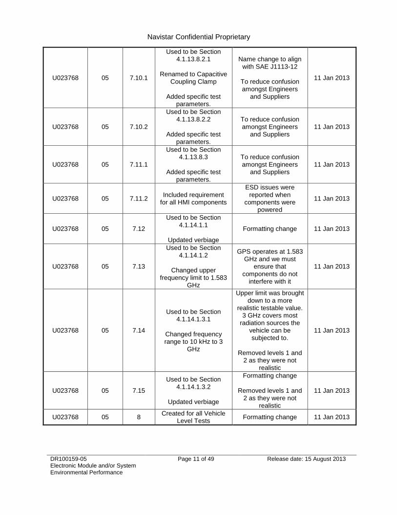
U023768 05 7.10.1
Used to be Section 4.1.13.8.2.1
Renamed to Capacitive
Coupling Clamp
Added specific test parameters.
Name change to align with SAE J1113-12
To reduce confusion amongst Engineers
and Suppliers
11 Jan 2013
U023768 05 7.10.2
Used to be Section 4.1.13.8.2.2
Added specific test
parameters.
To reduce confusion amongst Engineers
and Suppliers 11 Jan 2013
U023768 05 7.11.1
Used to be Section 4.1.13.8.3
Added specific test
parameters.
To reduce confusion amongst Engineers
and Suppliers 11 Jan 2013
U023768 05 7.11.2 Included requirement
for all HMI components
ESD issues were reported when
components were powered
11 Jan 2013
U023768 05 7.12
Used to be Section 4.1.14.1.1
Updated verbiage
Formatting change 11 Jan 2013
U023768 05 7.13
Used to be Section 4.1.14.1.2
Changed upper
frequency limit to 1.583 GHz
GPS operates at 1.583 GHz and we must
ensure that components do not
interfere with it
11 Jan 2013
U023768 05 7.14
Used to be Section 4.1.14.1.3.1
Changed frequency range to 10 kHz to 3
GHz
Upper limit was brought down to a more
realistic testable value. 3 GHz covers most
radiation sources the vehicle can be subjected to.
Removed levels 1 and
2 as they were not realistic
11 Jan 2013
U023768 05 7.15
Used to be Section 4.1.14.1.3.2
Updated verbiage
Formatting change
Removed levels 1 and 2 as they were not
realistic
11 Jan 2013
U023768 05 8 Created for all Vehicle
Level Tests Formatting change 11 Jan 2013

Navistar Confidential Proprietary
DR100159-05 Electronic Module and/or System Environmental Performance
Page 12 of 49 Release date: 15 August 2013
U023768 05 8.1
Used to be Section 4.1.13.8.3.2
Added specific test
parameters.
To reduce confusion amongst Engineers
and Suppliers 11 Jan 2013
U023768 05 8.2
Used to be Section 4.1.14.2.1
Updated verbiage
Formatting change 11 Jan 2013
U023768 05 8.3
Used to be Section 4.1.14.2.2.2
Changed frequency range to 10 kHz to 3
GHz
Reference changed to ISO 11451-2.
Upper limit was brought
down to a more realistic testable value.
3 GHz covers most radiation sources the
vehicle can be subjected to.
11 Jan 2013
U023768 05 8.4 Included new requirement
Documented SINAD test that was being
performed on Navistar vehicles per regulation of certain U.S. States
11 Jan 2013
U023768 05 9
Used to be Section 4.2.1
Updated to separate
electrical and mechanical tests.
Included new tests.
Updated to reflect new test requirements
11 Jan 2013
U023768 05 9.1
Included to show test flow when using
Combined Environmental testing to
replace Temperature Cycling, Humidity, and
Vibration
Updated to reflect new test requirements
11 Jan 2013
U023768 05 5.2 Included 60 min soak at
each temperature Test length was not
clear previously 01 Jul 2013
U023768 05 5.7
Used to be Section 5.6.3. Frost testing
method was not defined in SAE. Test structured based on prior lessons learned. Moved away
from Humidity subsection
Test method was not defined in SAE
01 Jul 2013
U023768 05 5.12 Removed ―Optional‖
wording
Removed ―Optional‖ to make requirements more consistent with
rest of DRD.
01 Jul 2013

Navistar Confidential Proprietary
DR100159-05 Electronic Module and/or System Environmental Performance
Page 13 of 49 Release date: 15 August 2013
U023768 05 7.15
Specified Calibrated Injection Probe Method as the method to test
BCI
Method was not previously defined in
DRD. 01 Jul 2013
U023768 05 9 Rearranged Test Flow
Moved more destructive tests near the end of test legs so they do not interrupt
long testing
01 Jul 2013
U023768 05 9.1 Rearranged Test Flow
Moved more destructive tests near the end of test legs so they do not interrupt
long testing
01 Jul 2013
U023768 05 10 Included Reliability Test
Requirements
Was not required before. Shall be
defined in component DRD
01 Jul 2013
U023768 05 7.4 Updated Reverse
Polarity spec
Included new specifications for
devices capable of driving external loads
greater than 5 A.
31 Jul 2013
U023768 05 7.4 Updated Reverse
Polarity spec
Changed specifications for devices capable of driving external loads
05 Aug 2013
U023768 05 7.14 Updated Radiated
Immunity Spec
Changed frequency step size to cover SAE
J1113-4 and ISO 11452-1 requirements
05 Aug 2013
U023768 05 7.15 Updated Bulk Current
Injection Spec
Changed frequency step size to cover SAE
J1113-4 and ISO 11452-1 requirements
05 Aug 2013
U023768 05 8.3 Updated Vehicle Level Radiated Susceptibility
Spec
Changed frequency step size to cover SAE
J1113-4 and ISO 11452-1 requirements
06 Aug 2013
Table 1: Revision Summary

Navistar Confidential Proprietary
DR100159-05 Electronic Module and/or System Environmental Performance
Page 14 of 49 Release date: 15 August 2013
2. Scope
2.1. Purpose
This environmental specification is to be used in conjunction with the component and/or system specification to qualify the components and/or systems for application on Navistar vehicles. This specification sets the testing parameters required to assure acceptable operation within the vehicle environment for electronic modules and/or systems, which are used on Navistar vehicles. This specification evaluates electronic modules and/or systems for acceptable life when those modules and systems must function on Navistar vehicles.
2.2. Description
This general environmental specification is a recommended requirement. The device(s) specification shall take precedence over this document. The device(s) specification shall indicate the Test Class and Status levels.

Navistar Confidential Proprietary
DR100159-05 Electronic Module and/or System Environmental Performance
Page 15 of 49 Release date: 15 August 2013
3. Applicable Documents
3.1. Industry Standards
Document Revision Title
CISPR 12 MAR 2009 Vehicles, boats and internal combustion engines . Radio disturbance characteristics . Limits and methods of measurement for the protection of off-board receivers
CISPR 25 MAR 2008 Vehicles, boats and internal combustion engines – Radio disturbance characteristics – Limits and methods of measurement for the protection of on-board receivers
ISO 11451-2 FEB 2005 Road vehicles — Vehicle test methods for electrical disturbances from narrowband radiated electromagnetic energy — Part 2: Off-vehicle radiation sources
ISO 12103-1 DEC 1997 Road vehicles — Test dust for filter evaluation
ISO 22241-1 OCT 2006 Diesel engines — NOx reduction agent AUS 32
MIL-STD-202G FEB 2002 Department of Defense – Test Method Standard – Electronic and Electrical Component Parts
MIL-STD-810G OCT 2008 Department of Defense – Test Method Standard – Environmental Engineering Considerations and Laboratory Tests
SAE J400 OCT 2012 Test for Chip Resistance of Surface Coatings
SAE J551-1 JUN 2010 Performance Levels and Methods of Measurement of Electromagnetic Compatibility of Vehicles, Boats (up to 15 m), and Machines (16.6 Hz to 18 GHz)
SAE J1113-1 MAR 2012 Electromagnetic Compatibility Measurement Procedures and Limits for Components of Vehicles, Boats (up to 15 m), and Machines (Except Aircraft) (16.6 Hz to 18 GHz)
SAE J1113-4 AUG 2004 Immunity to Radiated Electromagnetic Fields—Bulk Current Injection (BCI) Method
SAE J1113-11 JAN 2012 Immunity to Conducted Transients on Power Leads
SAE J1113-12 AUG 2006 Electrical Interference by Conduction and Coupling— Capacitive and Inductive Coupling via Lines Other than Supply Lines
SAE J1113-13 JUN 2011 Electromagnetic Compatibility Measurement Procedure for Vehicle Components - Part 13: Immunity to Electrostatic Discharge
SAE J1113-21 OCT 2005 Electronmagnetic Compatibility Measurement Procedure for Vehicle Components— Part 21: Immunity to Electromagnetic Fields, 30 MHz to 18 GHz, Absorber Lined Chamber
SAE J1455 AUG 2012 Recommended Environmental Practices for Electronic Equipment Design in Heavy-Duty Vehicle Applications
UN ECE R 10-04 MAR 2012 Vehicles with regard to electromagnetic compatibility
Table 2: Industry Standards
3.2. Navistar Documents
Document Revision Title
EES-SE-V-0001 1.0 Vehicle System Requirements – Electrical
Table 3: Navistar Documents

Navistar Confidential Proprietary
DR100159-05 Electronic Module and/or System Environmental Performance
Page 16 of 49 Release date: 15 August 2013
4. Definitions and Nomenclature
4.1. Functional Test
The functional test is intended to be a very basic quick test that simply verifies that the DUT is operational. This test needs only to take attribute data. Items such as verifying that an output is on or off, that an output responds when an input signal is present, etc.
4.2. Parametric Test
The parametric test is intended to be an extensive and detailed test that measures variable data on all of the functionality as well as each of the I/O of the DUT. The test steps shall measure variable data on items such as output voltage from high side drivers, saturation voltage on low side drivers, switching thresholds on digital inputs, leakage currents on output drivers, response curves on sensors, etc.
4.3. Functional Class
This element classifies the operational status of the function for an electrical/electronic device within the vehicle:
Class A — Any function that provides a convenience (e.g., entertainment, comfort).
Class B — Any function that enhances, but is not essential to the operation or control of the vehicle (e.g., TPMS).
Class C — Any function that is essential to the operation or control of the vehicle (e.g., braking, engine management).
4.4. Status of Performance
This element defines the expected performance objectives of the device under test subjected to the test conditions.
Status I—Normal Performance within the specification limits during and after exposure to a disturbance.
Status II—Temporary degradation or loss of function or performance that which is self-recoverable after the disturbance is removed.
Status III—Temporary degradation or loss of function or performance which requires operator intervention or system reset after the disturbance is removed.
Status IV—The device/function shall not have sustained any damage after the disturbance is removed.
Navistar Confidential Proprietary
DR100159-05 Electronic Module and/or System Environmental Performance
Page 17 of 49 Release date: 15 August 2013
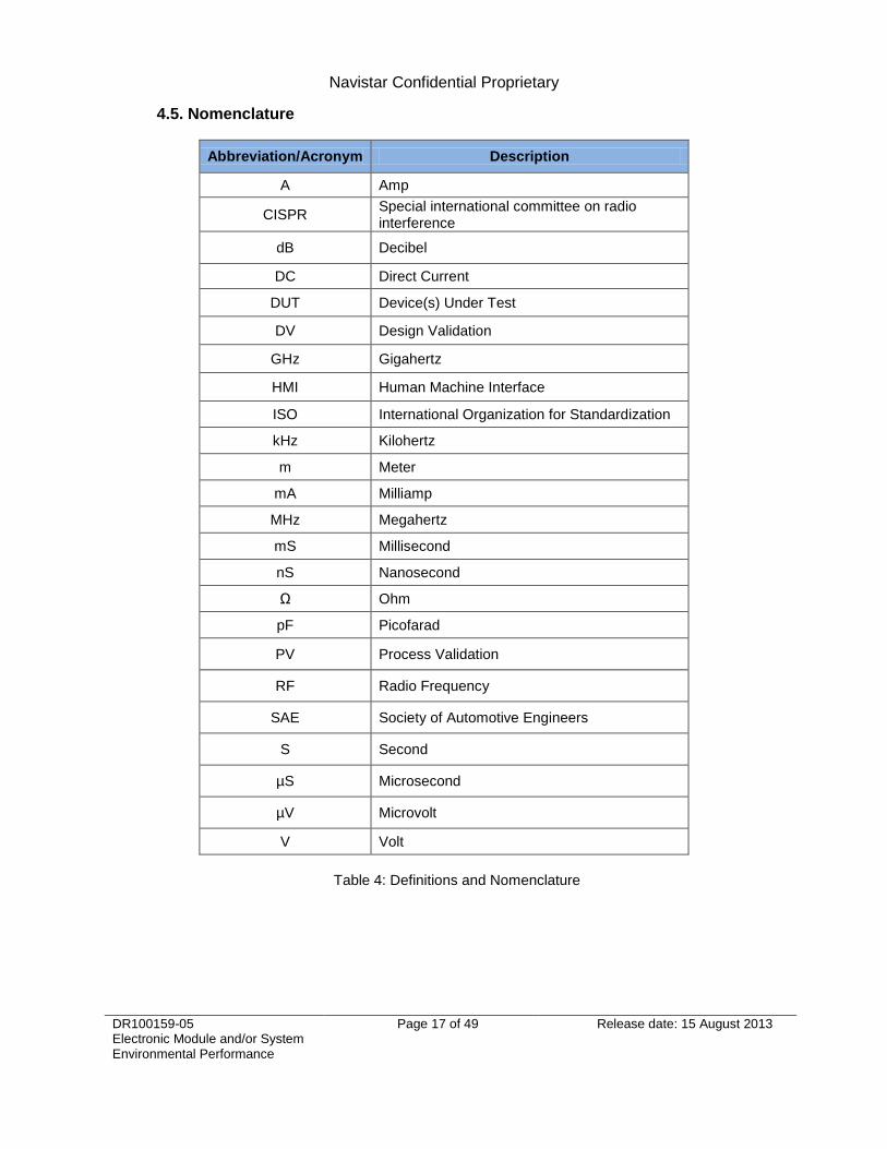
4.5. Nomenclature
Abbreviation/Acronym Description
A Amp
CISPR Special international committee on radio interference
dB Decibel
DC Direct Current
DUT Device(s) Under Test
DV Design Validation
GHz Gigahertz
HMI Human Machine Interface
ISO International Organization for Standardization
kHz Kilohertz
m Meter
mA Milliamp
MHz Megahertz
mS Millisecond
nS Nanosecond
Ω Ohm
pF Picofarad
PV Process Validation
RF Radio Frequency
SAE Society of Automotive Engineers
S Second
µS Microsecond
µV Microvolt
V Volt
Table 4: Definitions and Nomenclature

Navistar Confidential Proprietary
DR100159-05 Electronic Module and/or System Environmental Performance
Page 18 of 49 Release date: 15 August 2013
5. Climatic Environment
5.1. Operational Temperature
The DUT shall be capable of operating in the ambient temperature ranges listed in Table 5: Temperature based on the mounting location.
Mounting Location Minimum Temperature Maximum Temperature
In Cab -40⁰C 85⁰C
Chassis -40⁰C 125⁰C
Chassis (near heat source) -40⁰C 150⁰C
Engine Bay -40⁰C 125⁰C
Engine Bay (near heat source) -40⁰C 150⁰C
Table 5: Temperature
5.2. Three Temperature Parametric Test
The DUT shall be subjected to Three Temperature Parametric Tests to confirm functionality
prior and post DV/PV testing. The DUT shall first be soaked at 23⁰ ± 1⁰C for 60 minutes before taking parametric measurements. The DUT shall then be soaked at the minimum temperature as described in Section 5.1 for 60 minutes before taking parametric measurements. The DUT shall finally be soaked at the maximum temperature as described in Section 5.1 for 60 minutes before taking parametric measurements. Test Criteria: The DUT shall be subjected to the nominal voltage, minimum voltage, and maximum voltage as described in Section 7.1 during the test. The DUT shall meet all parametric test requirements during the test. Acceptance Criteria: The DUT shall meet all parametric test requirements following completion of the test without degradation of performance. The DUT shall not have sustained any physical damage following completion of the test. Reference: N/A
5.3. Storage Temperature Test
The DUT shall be subjected to a low storage temperature of -55⁰C for 24 hours and a high
storage temperature of 95⁰C for 48 hours. Test Criteria: The DUT is not required to meet functional test requirements during the test. Acceptance Criteria: The DUT shall meet all parametric test requirements following completion of the test without degradation of performance. The DUT shall not have sustained any physical damage following completion of the test. Reference: SAE J1455 REV AUG2012, Section 4.1.1.6, ―Ambient Conditions Before
Installation Due to Storage and Transportation Extremes‖ MIL-STD-810G REV OCT2008, Part One Annex C Table C-I, ―Summary of
climatic conditions and daily cycles of temperature, solar radiation, and relative humidity‖

Navistar Confidential Proprietary
DR100159-05 Electronic Module and/or System Environmental Performance
Page 19 of 49 Release date: 15 August 2013
5.4. Thermal Cycle Test
The DUT shall be subjected to the test cycle outlined in Figure 1: Temperature Cycle Test. One test cycle consists of varying temperature levels for 24 hours. The DUT shall be subjected to a total of 30 cycles (720 hours). The DUT shall be subjected to the minimum operating temperature to the maximum operating temperature as described in Section 5.1. A
typical fall time from 23⁰C to -40⁰C, MAX⁰C to 23⁰C should take approximately 1 hour. A typical rise time from -40⁰C to MAX⁰C should take approximately 2 hours.
4 8 16 20 24
MAX
Time (Hours)
Te
mp
era
ture
(°C
)
-40°
Figure 1: Thermal Cycle Test
12
23°
Test Criteria: The DUT shall be subjected to the nominal voltage as described in Section 7.1 during the test. The DUT shall meet all functional test requirements during the test. Acceptance Criteria: The DUT shall meet all parametric test requirements following completion of the test without degradation of performance. The DUT shall not have sustained any physical damage following completion of the test. Reference: SAE J1455 REV AUG2012, Section 4.1.3.1, ―Temperature Cycle Test‖ SAE J1455 REV AUG2012, Figure 2A, ―24 Hour Thermal Cycle Test‖
5.5. Thermal Shock Test
5.5.1. Thermal Shock Test (Short) The DUT shall be subjected to the test cycle outlined in Figure 2: Thermal Shock Test. One test cycle consists of a 1 hour soak at the minimum operating temperature as described in Section 5.1 followed by a transfer to the hot chamber for a 1 hour soak at the maximum operating temperature as described in Section 5.1. Each transfer shall occur in 1 minute or less. The DUT shall be subjected to a total of 84 cycles (168 hours).

Navistar Confidential Proprietary
DR100159-05 Electronic Module and/or System Environmental Performance
Page 20 of 49 Release date: 15 August 2013
Test Criteria: The DUT is not required to be operational during the test. Acceptance Criteria: The DUT shall meet all parametric test requirements following completion of the test without degradation of performance. The DUT shall not have sustained any physical damage following completion of the test. Reference: SAE J1455 REV AUG2012, Section 4.1.3.1, ―Temperature Cycle Test‖ SAE J1455 REV AUG2012, Figure 2A, ―24 Hour Thermal Cycle Test‖
5.5.2. Thermal Shock Test (Long)
The DUT shall be subjected to the test cycle outlined in Figure 2: Thermal Shock Test. One test cycle consists of a 1 hour soak at the minimum operating temperature as described in Section 5.1 followed by a transfer to the hot chamber for a 1 hour soak at the maximum operating temperature as described in Section 5.1. Each transfer shall occur in 1 minute or less. The DUT shall be subjected to a total of 500 cycles (1000 hours). This test is required for all Class C devices.
Test Criteria: The DUT is not required to meet functional test requirements during the test. Acceptance Criteria: The DUT shall meet all parametric test requirements following completion of the test without degradation of performance. The DUT shall not have sustained any physical damage following completion of the test. Reference: SAE J1455 REV AUG2012, Section 4.1.3.1, ―Temperature Cycle Test‖ SAE J1455 REV AUG2012, Figure 2A, ―24 Hour Thermal Cycle Test‖
1 2 3 4 5 6
MAX
Time (Hours)
Te
mp
era
ture
(°C
)-40°
Figure 2: Thermal Shock Test
Navistar Confidential Proprietary
DR100159-05 Electronic Module and/or System Environmental Performance
Page 21 of 49 Release date: 15 August 2013
5.6. Humidity Test
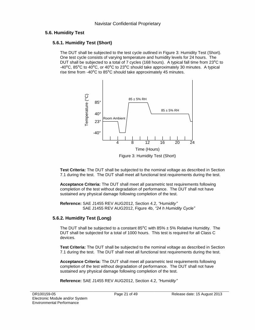
5.6.1. Humidity Test (Short)
The DUT shall be subjected to the test cycle outlined in Figure 3: Humidity Test (Short). One test cycle consists of varying temperature and humidity levels for 24 hours. The
DUT shall be subjected to a total of 7 cycles (168 hours). A typical fall time from 23⁰C to
-40⁰C, 85⁰C to 40⁰C, or 40⁰C to 23⁰C should take approximately 30 minutes. A typical
rise time from -40⁰C to 85⁰C should take approximately 45 minutes.
4 8 16 20 24
Time (Hours)
Te
mp
era
ture
(°C
)
-40°
Figure 3: Humidity Test (Short)
12
23°
85 ± 5% RH
85 ± 5% RH
Room Ambient
85°
40°
Test Criteria: The DUT shall be subjected to the nominal voltage as described in Section 7.1 during the test. The DUT shall meet all functional test requirements during the test. Acceptance Criteria: The DUT shall meet all parametric test requirements following completion of the test without degradation of performance. The DUT shall not have sustained any physical damage following completion of the test. Reference: SAE J1455 REV AUG2012, Section 4.2, ―Humidity‖ SAE J1455 REV AUG2012, Figure 4b, ―24 h Humidity Cycle‖
5.6.2. Humidity Test (Long)
The DUT shall be subjected to a constant 85⁰C with 85% ± 5% Relative Humidity. The DUT shall be subjected for a total of 1000 hours. This test is required for all Class C devices. Test Criteria: The DUT shall be subjected to the nominal voltage as described in Section 7.1 during the test. The DUT shall meet all functional test requirements during the test. Acceptance Criteria: The DUT shall meet all parametric test requirements following completion of the test without degradation of performance. The DUT shall not have sustained any physical damage following completion of the test. Reference: SAE J1455 REV AUG2012, Section 4.2, ―Humidity‖

Navistar Confidential Proprietary
DR100159-05 Electronic Module and/or System Environmental Performance
Page 22 of 49 Release date: 15 August 2013
5.7. Frost Test
The DUT shall be soaked at -40⁰C for 60 minutes. With laboratory humidity at a minimum of 40% relative humidity, the environmental chamber shall be powered off with the door open to induce frost on the DUT. Testing shall be performed within 5 minutes of the environmental chamber door being opened. Test Criteria: The DUT shall be subjected to the nominal voltage as described in Section 7.1 during the test. The DUT shall meet all functional test requirements during the test. Acceptance Criteria: The DUT shall meet all functional test requirements during the test. The DUT shall meet all parametric test requirements following completion of the test without degradation of performance. The DUT shall not have sustained any physical damage following completion of the test. Reference: SAE J1455 REV AUG2012, Section 4.2, ―Humidity‖
5.8. Salt Spray Test
The DUT shall be subjected to a salt spray consisting of 5 parts NaCL to 95 parts water at
35⁰C. The DUT shall be subjected to the number of hours outlined in Table 6: Salt Spray Test depending on mounting location for each salt solution. This test shall be repeated with 5
parts of MgCL2 to 95 parts water at 35⁰C. The DUT shall be rinsed in deionized water between each salt exposure. The DUT shall be mated with a sealed connector for this test. The use of unsealed connectors must be approved in writing by Navistar Engineering.
Mounting Location Hours of Exposure
In Cab 96 Hours
Chassis 240 Hours
Engine Bay 240 Hours
Table 6: Salt Spray Test
Test Criteria: The DUT shall be subjected to the nominal voltage as described in Section 7.1 during the test. The DUT shall meet all functional test requirements during the test. Acceptance Criteria: The DUT shall meet all parametric test requirements following completion of the test without degradation of performance. The DUT shall not have sustained any physical damage following completion of the test. Reference: SAE J1455 REV AUG2012, Section 4.3.3.1, ―Salt Spray (Fog)‖
5.9. Immersion Test
The DUT shall be subjected to a water immersion consisting of 5 parts NaCL to 95 parts water at 74⁰C for 1 hour, then immediately transferred to the same salt water solution at 0⁰C for 1 hour. The DUT shall be immersed at a depth of 1 meter. This test shall be repeated with 5 parts of MgCL2 to 95 parts water. The DUT shall be rinsed in deionized water between each salt exposure. The DUT shall be mated with a sealed connector for this test. The use of unsealed connectors must be approved in writing by Navistar Engineering. Test Criteria: The DUT shall be subjected to the nominal voltage as described in Section 7.1 during the test. The DUT shall meet all functional test requirements during the test.

Navistar Confidential Proprietary
DR100159-05 Electronic Module and/or System Environmental Performance
Page 23 of 49 Release date: 15 August 2013
Acceptance Criteria: The DUT shall meet all parametric test requirements following completion of the test without degradation of performance. The DUT shall not have sustained any physical damage following completion of the test. Reference: SAE J1455 REV AUG2012, Section 4.3.3.2, ―Immersion Testing‖
5.10. Exposure to Chemicals and Oils
The DUT shall be subjected to a chemical exposure of the chemicals listed in Table 7: Chemicals and Oils. The device(s) DRD shall list all applicable chemicals based on the mounting location. For Chassis and Engine mounting locations, the DUT shall be subjected to 100% coverage using 80⁰ flat fan nozzles located 20 to 25 cm away. The DUT shall be subjected to 200kPa of pressure with a flow rate of 2650 cm
3/min. One test cycle consists of 5 minutes exposure
to the chemical followed by 5 minutes of no exposure. The DUT shall be subjected to a total of 2 cycles (20 minutes). For In Cab mounting locations, the DUT shall be subjected to liberal coating of the chemical via a chemically compatible brush. The DUT with the chemical applied shall be allowed to stand for 24 hours before being inspected. Chemical Immersion may be necessary for certain mounting locations. The DUT shall be subjected to chemical immersion for 5 to 10 minutes. The DUT with the chemical applied shall be allowed to stand for 24 hours before being inspected.
Chemicals and Oils
Engine Oils and Additives Battery Acid
Transmission Oil Waxes
Rear Axle Oil Kerosene
Power Steering Fluid Freon
Brake Fluid Spray Paint
Axle Grease Paint Strippers
Window Washer Solvent Ether
Gasoline Dust Control Agents (MgCl2)
Diesel Fuel Moisture Control Agents (CaCl2)
Fuel Additives Vinyl Plasticizers
Alcohol Undercoating Material
Anti-Freeze Water Mixture Muriatic Acid
Degreasers Ammonia
Soap and Detergents Steam
Diesel Exhaust Fluid (32.5% solution of high-purity urea in de-mineralized
water i.e. Aqueous Urea Solution 32 (ISO 22241))
Table 7: Chemicals and Oils

Navistar Confidential Proprietary
DR100159-05 Electronic Module and/or System Environmental Performance
Page 24 of 49 Release date: 15 August 2013
Test Criteria: The DUT shall be subjected to the nominal voltage as described in Section 7.1 during the test. The DUT shall meet all functional test requirements during the test. Acceptance Criteria: The DUT shall meet all parametric test requirements following completion of the test without degradation of performance. The DUT shall not have sustained any physical damage following completion of the test. Reference: SAE J1455 REV AUG2012, Section 4.4, ―Exposure to Chemicals and Oils‖ ISO 22241-1 REV OCT2006, ―Diesel engines — NOx reduction agent
AUS 32‖
5.11. Steam Cleaning and Pressure Washing
5.11.1. Pressure Washing
The DUT shall be subjected to a pressure wash. The device(s) DRD shall state the applicable test. The DUT shall be mated with a sealed connector for this test. This test is not required for unsealed modules with unsealed connectors. The DUT shall be subjected to 1400 kPa with a flow rate of 9460 cm
3/min of non-heated
tap water. The DUT shall be placed 20 to 30 cm away from the nozzles. The DUT shall
be subjected to spray for 3 seconds on each side of the component with a 15⁰ fan nozzle. The DUT shall be subjected to a total of 378 sprays. The DUT shall be subjected to 7000 kPa with a flow rate of 9460 cm
3/min of a wash
solution with detergent heated to 40⁰C. The DUT shall be placed 20 to 30 cm away from the nozzles. The DUT shall be subjected to spray for 3 seconds on each side of the
component with a 15⁰ fan nozzle. The DUT shall be subjected to a total of 378 sprays. Test Criteria: The DUT shall be subjected to the nominal voltage as described in Section 7.1 during the test. The DUT shall meet all functional test requirements during the test. Acceptance Criteria: The DUT shall meet all parametric test requirements following completion of the test without degradation of performance. The DUT shall not have sustained any physical damage following completion of the test. Reference: SAE J1455 REV AUG2012, Section 4.5, ―Steam Cleaning and Pressure Washing‖
5.11.2. Steam Cleaning The DUT shall be subjected to a pressure wash. The device(s) DRD shall state the applicable test. The DUT shall be mated with a sealed connector for this test. This test is not required for unsealed modules with unsealed connectors. The DUT shall be subjected to 1400 kPa with a flow rate of 9460 cm
3/min of tap water
heated to 93⁰C. The DUT shall be placed 20 to 30 cm away from the nozzles. The DUT
shall be subjected to spray for 3 seconds on each side of the component with a 15⁰ fan nozzle. The DUT shall be subjected to a total of 378 sprays. The DUT shall be subjected to 7000 kPa with a flow rate of 9460 cm
3/min of a wash
solution with detergent heated to 93⁰C. The DUT shall be placed 20 to 30 cm away from the nozzles. The DUT shall be subjected to spray for 3 seconds on each side of the
component with a 15⁰ fan nozzle. The DUT shall be subjected to a total of 378 sprays.

Navistar Confidential Proprietary
DR100159-05 Electronic Module and/or System Environmental Performance
Page 25 of 49 Release date: 15 August 2013
Test Criteria: The DUT shall be subjected to the nominal voltage as described in Section 7.1 during the test. The DUT shall meet all functional test requirements during the test. Acceptance Criteria: The DUT shall meet all parametric test requirements following completion of the test without degradation of performance. The DUT shall not have sustained any physical damage following completion of the test. Reference: SAE J1455 REV AUG2012, Section 4.5, ―Steam Cleaning and Pressure
Washing‖
5.12. Fungus
The DUT shall be subjected to a fungal spore mixture as described in MIL-STD-810G Method 508.6. The DUT shall be inoculated with the fungal spore and allowed to incubate under cyclic temperature and humidity conditions to promote growth. The fungal spore shall be allowed 30 days for growth. Test Criteria: The DUT shall be subjected to the nominal voltage as described in Section 7.1 during the test. The DUT shall meet all functional test requirements during the test. Acceptance Criteria: The DUT shall meet all parametric test requirements following completion of the test without degradation of performance. The DUT shall not have sustained any physical damage following completion of the test. Reference: MIL-STD-810G REV OCT2008, Method 508.6, ―Fungus SAE J1455 REV AUG2012, Section 4.6, ―Fungus‖
5.13. Altitude
5.13.1. Altitude (Operating)
The DUT shall be subjected to atmospheric conditions of 15,000 feet (4,372 meters) with 8.3 PSI (57.2 kPa) Absolute Pressure. The DUT shall be subjected for these atmospheric conditions for 24 hours. The DUT shall be subjected to temperature conditions of the Thermal Cycle Test as described in Section 5.4. Test Criteria: The DUT shall be subjected to the nominal voltage as described in Section 7.1 during the test. The DUT shall meet all functional test requirements during the test. Acceptance Criteria: The DUT shall meet all parametric test requirements following completion of the test without degradation of performance. The DUT shall not have sustained any physical damage following completion of the test. Reference: MIL-STD-810G REV OCT2008, Part Three Section 5.13, ―High elevations and upper air conditions‖
5.13.2. Altitude (Non-Operating)
The DUT shall be subjected atmospheric conditions of 50,000 feet (15,240 meters) with 1.45 PSI (10 kPa) Absolute Pressure. The DUT shall be subjected for these atmospheric conditions for 24 hours. The DUT shall be subjected to -55⁰C.

Navistar Confidential Proprietary
DR100159-05 Electronic Module and/or System Environmental Performance
Page 26 of 49 Release date: 15 August 2013
Test Criteria: The DUT is not required to meet functional test requirements during the test. Acceptance Criteria: The DUT shall meet all parametric test requirements following completion of the test without degradation of performance. The DUT shall not have sustained any physical damage following completion of the test. Reference: MIL-STD-810G REV OCT2008, Part Three Section 5.13, ―High elevations and upper air conditions‖
6. Mechanical Environment
6.1. Dust and Sand
The DUT shall be subjected a Dust and Sand Test using dust conforming to ISO 12103-1 A2 fine grade. The DUT shall be subjected to 23° ± 1°C. The DUT shall be subjected to an air/dust concentration of 0.88 g/m
3 for 24 hours.
Test Criteria: The DUT shall be subjected to the nominal voltage as described in Section 7.1 during the test. The DUT shall meet all functional test requirements during the test. Acceptance Criteria: The DUT shall meet all parametric test requirements following completion of the test without degradation of performance. The DUT shall not have sustained any physical damage following completion of the test. Reference: SAE J1455 REV AUG2012, Section 4.7, ―Dust and Sand‖
ISO 12103-1 REV DEC1997, ―Road vehicles — Test dust for filter evaluation‖
6.2. Gravel Bombardment
The DUT shall be subjected to a gravel bombardment with gravel being able to pass through a 15.86 mm (0.62 in) space screen, but retained on a 9.53 mm (0.38 in) space screen. The test shall be performed at 23° ± 1°C. The test shall follow the procedure outlined in SAE J400 REV NOV2002, Section 5. The DUT shall be mounted such that it replicates the proposed mounting location on the vehicle.
Test Criteria: The DUT shall be subjected to the nominal voltage as described in Section 7.1 during the test. The DUT shall meet all functional test requirements during the test. Acceptance Criteria: The DUT shall meet all parametric test requirements following completion of the test without degradation of performance. The DUT shall not have sustained any physical damage following completion of the test. Reference: SAE J400 REV OCT2012, ―Test for Chip Resistance of Surface Coatings‖
6.3. Combined Environmental Testing The DUT shall be subjected to a combined environmental test. One test cycle consists of the profile as described in SAE J1455 Figure 14. The DUT shall be subjected to the Random Vibration test as described in Section 6.5. The DUT shall be subjected to 3 test cycles.
Test Criteria: The DUT shall be subjected to the nominal voltage as described in Section 7.1 during the test. The DUT shall meet all functional test requirements during the test.

Navistar Confidential Proprietary
DR100159-05 Electronic Module and/or System Environmental Performance
Page 27 of 49 Release date: 15 August 2013
Acceptance Criteria: The DUT shall meet all parametric test requirements following completion of the test without degradation of performance. The DUT shall not have sustained any physical damage following completion of the test. Reference: SAE J1455 REV AUG2012, Section 4.12, ―Combined Environmental Testing‖ SAE J1455 REV AUG2012, Figure 14, ―’Combined Test Profile‖
6.4. Swept Sine Vibration Test
The DUT shall be subjected to a swept sine vibration test with a g-force value as outlined in Table 8: Swept Sine Vibration Test depending on the mounting location. One test cycle consists of the DUT being subjected to a sweep from 10 Hz to 2 kHz with a sweep rate of ½ octave per minute in each axis. The DUT shall be subjected to 3 cycles in each axis. The DUT shall dwell for 30 minutes at each of the major resonance frequencies.
Mounting Location g-force
In Cab 5 g (49 m/s2)
Chassis 5 g (49 m/s2)
Engine Bay 6 g (58.8 m/s2)
Table 8: Swept Sine Vibration Test
Test Criteria: The DUT shall be subjected to the nominal voltage as described in Section 7.1 during the test. The DUT shall meet all functional test requirements during the test. Acceptance Criteria: The DUT shall meet all parametric test requirements following completion of the test without degradation of performance. The DUT shall not have sustained any physical damage following completion of the test. Reference: SAE J1455 REV AUG2012, Section 4.10.4.1, ―Swept Sine Vibration Tests‖
SAE J1455 REV AUG2012, Figure A1, ―Maximum Expected Truck Acceleration Levels‖
6.5. Random Vibration Testing
The DUT shall be subjected to a random vibration test. The DUT shall be subjected to the SAE J1455 vibration profile as outlined in Table 9: Random Vibration Test depending on the mounting location. The DUT shall be subjected to the number of hours in each axis outlined in Table 9: Random Vibration Test depending on mounting location. Data acquired from the vehicle mounting location shall be used when available.
Mounting Location SAE J1455 Vibration Profile Hours
In Cab Figure 6, 7, 8 22
Chassis Figure 10, 11 22
Engine Bay Figure 9 22
Table 9: Random Vibration Test
Test Criteria: The DUT shall be subjected to the nominal voltage as described in Section 7.1 during the test. The DUT shall meet all functional test requirements during the test.

Navistar Confidential Proprietary
DR100159-05 Electronic Module and/or System Environmental Performance
Page 28 of 49 Release date: 15 August 2013
Acceptance Criteria: The DUT shall meet all parametric test requirements following completion of the test without degradation of performance. The DUT shall not have sustained any physical damage following completion of the test. Reference: SAE J1455 REV AUG2012, Section 4.10.4.2, ―Random Vibration Testing‖
SAE J1455 REV AUG2012, Figure 6, ―SAMPLE CAB MOUNTED VIBRATION PSD CLASS 8 TRUCK, VERTICAL AXIS‖ SAE J1455 REV AUG2012, Figure 7, ―SAMPLE CAB MOUNTED VIBRATION PSD TRANSVERSE AXIS‖ SAE J1455 REV AUG2012, Figure 8, ―SAMPLE CAB MOUNTED VIBRATION PSD CLASS 8 TRUCK, LONGITUDINAL AXIS‖ SAE J1455 REV AUG2012, Figure 9, ―SAMPLE ENGINE VIBRATION DATA (VERTICAL), HEAVY-DUTY TRUCK‖ SAE J1455 REV AUG2012, Figure 10, ―CHASSIS VIBRATION DATA, PSD, BOBTAIL VERTICAL MID FRAME, HEAVY-DUTY TRUCK‖ SAE J1455 REV AUG2012, Figure 11, ―CHASSIS VIBRATION DATA, PSD, BOBTAIL VERTICAL REAR FRAME, HEAVY-DUTY TRUCK‖
6.6. Handling Drop Test
The DUT shall be subjected to a handling drop test from a 1 meter height onto a level concrete surface two times in each of the three mutually perpendicular planes. The DUT shall be dropped on both the positive and negative plane under test (e.g. ± x for the first DUT, ± y for the second DUT, ± z for the third DUT).
Test Criteria: The DUT is not required to meet functional test requirements during the test. Acceptance Criteria: The DUT shall meet all parametric test requirements following completion of the test without degradation of performance if there is no obvious physical damage. The DUT is not required to meet parametric test requirements following completion of the test if there is obvious physical damage (e.g. cracked housing, broken connector). Reference: SAE J1455 REV AUG2012, Section 4.11.3.1, ―Handling Drop Test‖
6.7. Transit Drop Test
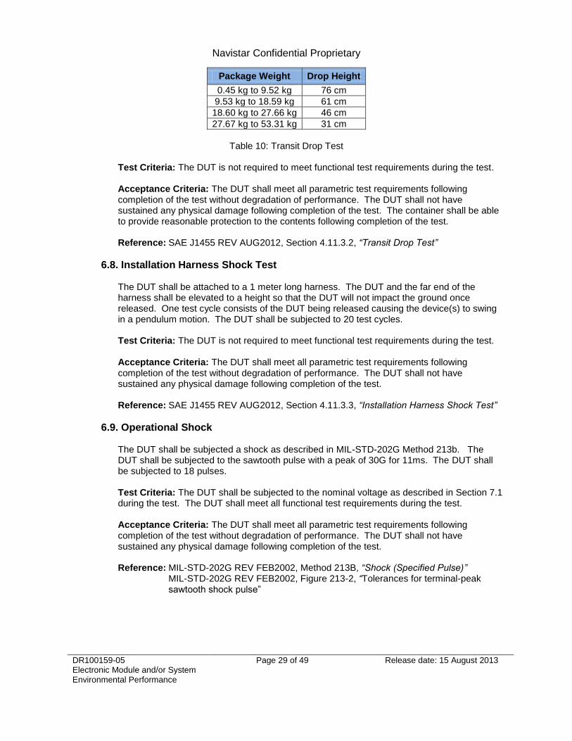
The DUT shall be placed into the container that it will be normally shipping in. The container shall be fully loaded as it would be in shipping. The container shall be subjected to a drop from a height as outlined in Table 10: Transit Drop Test. The container shall be subjected to drops in the following order:
The corner formed by the right side, bottom, and near end
The shortest edge radiating from that corner
The next longest edge radiating from that corner
The longest edge radiating from that corner
Flat on one of the smallest faces
Flat on the opposite small face
Flat on one of the medium faces
Flat on the opposite medium face
Flat on one of the largest faces
Flat on the opposite large face
Navistar Confidential Proprietary
DR100159-05 Electronic Module and/or System Environmental Performance
Page 29 of 49 Release date: 15 August 2013
Package Weight Drop Height
0.45 kg to 9.52 kg 76 cm
9.53 kg to 18.59 kg 61 cm
18.60 kg to 27.66 kg 46 cm
27.67 kg to 53.31 kg 31 cm
Table 10: Transit Drop Test
Test Criteria: The DUT is not required to meet functional test requirements during the test. Acceptance Criteria: The DUT shall meet all parametric test requirements following completion of the test without degradation of performance. The DUT shall not have sustained any physical damage following completion of the test. The container shall be able to provide reasonable protection to the contents following completion of the test. Reference: SAE J1455 REV AUG2012, Section 4.11.3.2, ―Transit Drop Test‖
6.8. Installation Harness Shock Test
The DUT shall be attached to a 1 meter long harness. The DUT and the far end of the harness shall be elevated to a height so that the DUT will not impact the ground once released. One test cycle consists of the DUT being released causing the device(s) to swing in a pendulum motion. The DUT shall be subjected to 20 test cycles. Test Criteria: The DUT is not required to meet functional test requirements during the test. Acceptance Criteria: The DUT shall meet all parametric test requirements following completion of the test without degradation of performance. The DUT shall not have sustained any physical damage following completion of the test. Reference: SAE J1455 REV AUG2012, Section 4.11.3.3, ―Installation Harness Shock Test‖
6.9. Operational Shock
The DUT shall be subjected a shock as described in MIL-STD-202G Method 213b. The DUT shall be subjected to the sawtooth pulse with a peak of 30G for 11ms. The DUT shall be subjected to 18 pulses. Test Criteria: The DUT shall be subjected to the nominal voltage as described in Section 7.1 during the test. The DUT shall meet all functional test requirements during the test. Acceptance Criteria: The DUT shall meet all parametric test requirements following completion of the test without degradation of performance. The DUT shall not have sustained any physical damage following completion of the test. Reference: MIL-STD-202G REV FEB2002, Method 213B, ―Shock (Specified Pulse)‖
MIL-STD-202G REV FEB2002, Figure 213-2, ―Tolerances for terminal-peak sawtooth shock pulse‖
Navistar Confidential Proprietary
DR100159-05 Electronic Module and/or System Environmental Performance
Page 30 of 49 Release date: 15 August 2013
7. Electrical Environment
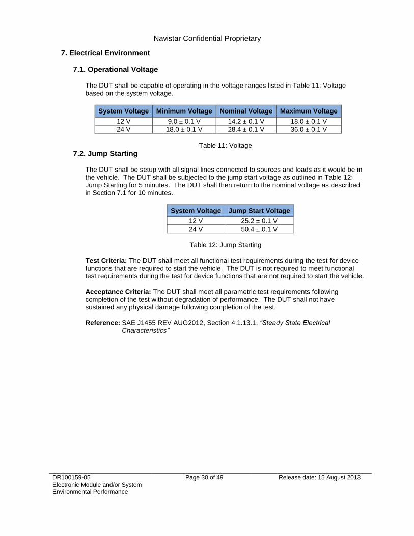
7.1. Operational Voltage
The DUT shall be capable of operating in the voltage ranges listed in Table 11: Voltage based on the system voltage.
System Voltage Minimum Voltage Nominal Voltage Maximum Voltage
12 V 9.0 ± 0.1 V 14.2 ± 0.1 V 18.0 ± 0.1 V
24 V 18.0 ± 0.1 V 28.4 ± 0.1 V 36.0 ± 0.1 V
Table 11: Voltage
7.2. Jump Starting The DUT shall be setup with all signal lines connected to sources and loads as it would be in the vehicle. The DUT shall be subjected to the jump start voltage as outlined in Table 12: Jump Starting for 5 minutes. The DUT shall then return to the nominal voltage as described in Section 7.1 for 10 minutes.
System Voltage Jump Start Voltage
12 V 25.2 ± 0.1 V
24 V 50.4 ± 0.1 V
Table 12: Jump Starting
Test Criteria: The DUT shall meet all functional test requirements during the test for device functions that are required to start the vehicle. The DUT is not required to meet functional test requirements during the test for device functions that are not required to start the vehicle. Acceptance Criteria: The DUT shall meet all parametric test requirements following completion of the test without degradation of performance. The DUT shall not have sustained any physical damage following completion of the test. Reference: SAE J1455 REV AUG2012, Section 4.1.13.1, ―Steady State Electrical
Characteristics‖

Navistar Confidential Proprietary
DR100159-05 Electronic Module and/or System Environmental Performance
Page 31 of 49 Release date: 15 August 2013
7.3. Cold Cranking
The DUT shall be setup with all signal lines connected to sources and loads as it would be in the vehicle. The DUT shall be subjected test cycle outlined in Figure 4: Cold Cranking. One test cycle consists of varying voltage levels. The DUT shall be subjected to a total of 20 cycles. The DUT shall then return to the nominal voltage as described in Section 7.1 for 10 minutes.
5 m
s
Time
Vo
lta
ge
(V
)
VS
Figure 4: Cold Cranking
VA
VN
20
0 m
s
8±2
ms
8±2
ms
30
s
5 s
System Voltage VA VS VN
12 V 6.0 ± 0.1 V 4.5 ± 0.1 V 12.2 ± 0.1 V
24 V 12.0 ± 0.1 V 6.0 ± 0.1 V 24.4 ± 0.1 V
Table 13: Cold Cranking
Test Criteria: The DUT shall meet all functional test requirements during the test for device functions that are required to start the vehicle. The DUT is not required to meet functional test requirements during the test for device functions that are not required to start the vehicle. Acceptance Criteria: The DUT shall meet all parametric test requirements following completion of the test without degradation of performance. The DUT shall not have sustained any physical damage following completion of the test. Reference: SAE J1455 REV AUG2012, Section 4.1.13.1, ―Steady State Electrical
Characteristics‖ SAE J1113-11 REV JAN2012, Figure 7, ―Test Pulse 4‖

Navistar Confidential Proprietary
DR100159-05 Electronic Module and/or System Environmental Performance
Page 32 of 49 Release date: 15 August 2013
7.4. Reverse Polarity
The DUT shall be setup with all signal lines connected to sources and loads as it would be in the vehicle. The DUT shall be subjected to the reverse battery voltage as outlined in Table 14: Reverse Polarity for 5 minutes. The DUT shall then return to the nominal voltage as described in Section 7.1 for 10 minutes. A power device is considered to be any device that drives an external load. All analog and digital logic circuitry on power devices shall be protected against -28.4 ± 0.1 V.
System Voltage Reverse Voltage
Power Devices -14.2 ± 0.1 V
Non-Power Devices -28.4 ± 0.1 V
Table 14: Reverse Polarity
Test Criteria: The DUT is not required to meet functional test requirements during the test. Acceptance Criteria: The DUT shall meet all parametric test requirements following completion of the test without degradation of performance. The DUT shall not have sustained any physical damage following completion of the test. Reference: SAE J1455 REV AUG2012, Section 4.1.13.1, ―Steady State Electrical
Characteristics‖
7.5. Voltage Regulator Failure
The DUT shall be setup with all signal lines to sources and loads as it would be in the vehicle. The DUT shall be subjected to the minimum voltage as outlined in Table 15: Voltage Regulator Failure for 1 hour. The DUT shall then return to the nominal voltage as outlined in Table 15: Voltage Regulator Failure for 10 minutes. The DUT shall then be subjected to the maximum voltage as outlined in Table 15: Voltage Regulator Failure for 1 hour. The DUT shall then return to the nominal voltage as described in Section 7.1 for 10 minutes.
System Voltage Minimum Voltage Maximum Voltage
12 V 9.0 ± 0.1 V 18.0 ± 0.1 V
24 V 18.0 ± 0.1 V 36.0 ± 0.1 V
Table 15: Voltage Regulator Failure
Test Criteria: The DUT shall meet all functional test requirements during the test for device functions that are required to start the vehicle. The DUT is not required to meet functional test requirements during the test for device functions that are not required to start the vehicle. Acceptance Criteria: The DUT shall meet all parametric test requirements following completion of the test without degradation of performance. The DUT shall not have sustained any physical damage following completion of the test. Reference: SAE J1455 REV AUG2012, Section 4.1.13.1, ―Steady State Electrical
Characteristics‖
Navistar Confidential Proprietary
DR100159-05 Electronic Module and/or System Environmental Performance
Page 33 of 49 Release date: 15 August 2013
7.6. Open Circuit
The DUT shall be setup with all signal lines connected to sources and loads as it would be in the vehicle. The DUT shall be subjected to the nominal voltage as described in Section 7.1. Disconnect one lead for at least 5 minutes then reconnect the lead. This test shall be repeated for each lead. Test Criteria: The DUT is not required to meet functional test requirements during the test. Acceptance Criteria: The DUT shall meet all parametric test requirements following completion of the test without degradation of performance. The DUT shall not have sustained any physical damage following completion of the test. Reference: N/A
7.7. Short Circuit
The DUT shall be setup with all signal lines connected to sources and loads as it would be in the vehicle. The DUT shall be connected with a 3 foot long 16 AWG lead. The DUT shall be subjected to the nominal voltage as described in Section 7.1. Connect one lead at a time to ground for at least 5 minutes. This test shall be repeated for each lead. Connect one lead at a time to the nominal voltage as described in Section 7.1 for at least 5 minutes. This test shall be repeated for each lead. This test shall be repeated with the DUT subjected to the maximum temperature as described in Section 5.1 and the minimum voltage as described in Section 7.1. Test Criteria: The DUT is not required to meet functional test requirements during the test. Circuit protection devices may be activated. Acceptance Criteria: The DUT shall meet all parametric test requirements following completion of the test without degradation of performance. The DUT shall not have sustained any physical damage following completion of the test. Reference: N/A
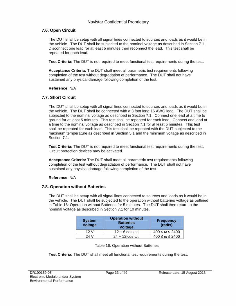
7.8. Operation without Batteries
The DUT shall be setup with all signal lines connected to sources and loads as it would be in the vehicle. The DUT shall be subjected to the operation without batteries voltage as outlined in Table 16: Operation without Batteries for 5 minutes. The DUT shall then return to the nominal voltage as described in Section 7.1 for 10 minutes.
System Voltage
Operation without Batteries Voltage
Frequency (rad/s)
12 V 12 + 6|cos ωt| 400 ≤ ω ≤ 2400
24 V 24 + 12|cos ωt| 400 ≤ ω ≤ 2400
Table 16: Operation without Batteries
Test Criteria: The DUT shall meet all functional test requirements during the test.

Navistar Confidential Proprietary
DR100159-05 Electronic Module and/or System Environmental Performance
Page 34 of 49 Release date: 15 August 2013
Acceptance Criteria: The DUT shall meet all parametric test requirements following completion of the test without degradation of performance. The DUT shall not have sustained any physical damage following completion of the test. Reference: N/A
7.9. Conducted Transients
7.9.1. Inductive Switching - Pulse 1
The DUT shall be setup with all signal lines connected to sources and loads as it would be in the vehicle. The DUT shall be subjected to SAE J1113-11 Pulse 1 with the parameters as outlined in Table 17: Pulse 1. The DUT shall be subjected to 5000 pulses.
Parameters 12 Volt System 24 Volt System
VS -600 V -600 V
Ri 20 Ω 50 Ω
td 1 ms 1 ms
tr 1 µs +0/-50% 3 µs +0/-50%
t1 0.5 s 0.5 s
t2 200 ms 200 ms
t3 < 100 µs < 100 µs
Table 17: Pulse 1
Test Criteria: The DUT shall be subjected to the nominal voltage as described in Section 7.1 during the test. The DUT shall meet all functional test requirements during the test. Acceptance Criteria: The DUT shall meet all parametric test requirements following completion of the test without degradation of performance. The DUT shall not have sustained any physical damage following completion of the test. Reference: SAE J1113-11 REV JAN2012, Section 5, ―Test Procedure‖ SAE J1113-11 REV JAN2012, Figure 2, ―Test Pulse 1‖
7.9.2. Inductive Switching - Pulse 2a
The DUT shall be setup with all signal lines connected to sources and loads as it would be in the vehicle. The DUT shall be subjected to SAE J1113-11 Pulse 2a with the parameters as outlined in Table 18: Pulse 2a. The DUT shall be subjected to 5000 pulses.
Parameters 12 Volt System 24 Volt System
VS +75 V +75 V
Ri 2 Ω 2 Ω
td 0.05 ms 0.05 ms
tr 1 µs +0/-50% 1 µs +0/-50%
t1 0.2 s 0.2 s
Table 18: Pulse 2a

Navistar Confidential Proprietary
DR100159-05 Electronic Module and/or System Environmental Performance
Page 35 of 49 Release date: 15 August 2013
Test Criteria: The DUT shall be subjected to the nominal voltage as described in Section 7.1 during the test. The DUT shall meet all functional test requirements during the test. Acceptance Criteria: The DUT shall meet all parametric test requirements following completion of the test without degradation of performance. The DUT shall not have sustained any physical damage following completion of the test. Reference: SAE J1113-11 REV JAN2012, Section 5, ―Test Procedure‖ SAE J1113-11 REV JAN2012, Figure 3, ―Test Pulse 2a‖
7.9.3. Inductive Switching - Pulse 2b
The DUT shall be setup with all signal lines connected to sources and loads as it would be in the vehicle. The DUT shall be subjected to SAE J1113-11 Pulse 2b with the parameters as outlined in Table 19: Pulse 2b. The DUT shall be subjected to 10 pulses.
Parameters 12 Volt System 24 Volt System
VS 10 V 20 V
Ri ≤ 0.05 Ω ≤ 0.05 Ω
td 2 s 2 s
t1 1 ms ± 50% 1 ms ± 50%
tr 1 ms ± 50% 1 ms ± 50%
t6 1 ms ± 50% 1 ms ± 50%
Table 19: Pulse 2b
Test Criteria: The DUT shall be subjected to the nominal voltage as described in Section 7.1 during the test. The DUT shall meet all functional test requirements during the test. Acceptance Criteria: The DUT shall meet all parametric test requirements following completion of the test without degradation of performance. The DUT shall not have sustained any physical damage following completion of the test. Reference: SAE J1113-11 REV JAN2012, Section 5, ―Test Procedure‖ SAE J1113-11 REV JAN2012, Figure 4, ―Test Pulse 2b‖
7.9.4. Switching Spikes - Pulse 3a
The DUT shall be setup with all signal lines connected to sources and loads as it would be in the vehicle. The DUT shall be subjected to SAE J1113-11 Pulse 3a with the parameters as outlined in Table 20: Pulse 3a. The DUT shall be subjected to the pulse for 1 hour.

Navistar Confidential Proprietary
DR100159-05 Electronic Module and/or System Environmental Performance
Page 36 of 49 Release date: 15 August 2013
Parameters 12 Volt System 24 Volt System
VS (from nominal voltage)
-150 V -200 V
Ri 50 Ω 50 Ω
td 0.1 µs +100/-0% 0.1 µs +100/-0%
tf 5 ns ± 30% 5 s ± 30%
t1 100 µs 100 µs
t4 10 ms 10 ms
t5 90 ms 90 ms
Table 20: Pulse 3a
Test Criteria: The DUT shall be subjected to the nominal voltage as described in Section 7.1 during the test. The DUT shall meet all functional test requirements during the test. Acceptance Criteria: The DUT shall meet all parametric test requirements following completion of the test without degradation of performance. The DUT shall not have sustained any physical damage following completion of the test. Reference: SAE J1113-11 REV JAN2012, Section 5, ―Test Procedure‖ SAE J1113-11 REV JAN2012, Figure 5, ―Test Pulse 3a‖
7.9.5. Switching Spikes - Pulse 3b
The DUT shall be setup with all signal lines connected to sources and loads as it would be in the vehicle. The DUT shall be subjected to SAE J1113-11 Pulse 3b with the parameters as outlined in Table 21: Pulse 3b. The DUT shall be subjected to the pulse for 1 hour.
Parameters 12 Volt System 24 Volt System
VS (from nominal voltage)
+100 V +200 V
Ri 50 Ω 50 Ω
td 0.1 µs +100/-0% 0.1 µs +100/-0%
tr 5 ns ± 30% 5 ns ± 30%
t1 100 µs 100 µs
t4 10 ms 10 ms
t5 90 ms 90 ms
Table 21: Pulse 3b
Test Criteria: The DUT shall be subjected to the nominal voltage as described in Section 7.1 during the test. The DUT shall meet all functional test requirements during the test. Acceptance Criteria: The DUT shall meet all parametric test requirements following completion of the test without degradation of performance. The DUT shall not have sustained any physical damage following completion of the test. Reference: SAE J1113-11 REV JAN2012, Section 5, ―Test Procedure‖ SAE J1113-11 REV JAN2012, Figure 6, ―Test Pulse 3b‖

Navistar Confidential Proprietary
DR100159-05 Electronic Module and/or System Environmental Performance
Page 37 of 49 Release date: 15 August 2013
7.9.6. Load Dump - Pulse 5a
The DUT shall be setup with all signal lines connected to sources and loads as it would be in the vehicle. The DUT shall be subjected to SAE J1113-11 Pulse 5a with the parameters as outlined in Table 22: Pulse 5a. The DUT shall be subjected to 40 pulses.
Parameters 12 Volt System 24 Volt System
VS (from nominal voltage)
87 V 174 V
Ri 1 Ω 1 Ω
td 400 ms 350 ms
tr 10 ms ± 5 ms 10 ms ± 5 ms
Table 22: Pulse 5a
Test Criteria: The DUT shall be subjected to the nominal voltage as described in Section 7.1 during the test. The DUT shall meet all functional test requirements during the test. Acceptance Criteria: The DUT shall meet all parametric test requirements following completion of the test without degradation of performance. The DUT shall not have sustained any physical damage following completion of the test. Reference: SAE J1113-11 REV JAN2012, Section 5, ―Test Procedure‖ SAE J1113-11 REV JAN2012, Figure 8, ―Test Pulse 5a & 5c‖
7.9.7. Low Side Outputs Bias by Ignition or Accessory
The DUT shall be setup with all signal lines connected to sources and loads as it would be in the vehicle. The DUT shall be subjected to SAE J1113-11 Pulse 1 on the active low side output channels for each low side driver output. A load resistance of 200 Ω shall be used on each output and connected through the bias side of the load. The DUT shall be subjected to the pulse on the biased side of the load while the biasing supply is switched off. The desired effect is to simulate and inductive load flyback voltage on the low side output cause by disruption of the ignition or accessory power to the loads. Test Criteria: The DUT shall be subjected to the nominal voltage as described in Section 7.1 during the test. The DUT shall meet all functional test requirements during the test. Acceptance Criteria: The DUT shall meet all parametric test requirements following completion of the test without degradation of performance. The DUT shall not have sustained any physical damage following completion of the test. Reference: SAE J1113-11 REV JAN2012, Section 5, ―Test Procedure‖ SAE J1113-11 REV JAN2012, Figure 2, ―Test Pulse 1‖
7.10. Coupled Transients
7.10.1. Capacitive Coupling Clamp
The DUT shall be setup with all signal lines connected to sources and loads as it would be in the vehicle. The DUT shall be subjected to SAE J1113-12 Pulse A and Pulse B with the parameters as outlined in Table 23: Capacitive Coupling Clamp. The DUT shall be subjected to 10 seconds of pulses on each signal line.

Navistar Confidential Proprietary
DR100159-05 Electronic Module and/or System Environmental Performance
Page 38 of 49 Release date: 15 August 2013
Parameters 12 Volt System 24 Volt System
Pulse A
VS 0 V to -60 V 0 V to -80 V
Rs1 50 Ω 50 Ω
T 0.1 µs +100/-0% 0.1 µs +100/-0%
Tr 5 ns ± 50% 5 ns ± 50%
t1 100 µs 100 µs
t2 10 ms 10 ms
t3 ≥ 90 ms ≥ 90 ms
Pulse B
VS 0 V to +40 V 0 V to +80 V
Rs1 50 Ω 50 Ω
T 0.1 µs +100/-0% 0.1 µs +100/-0%
Tr 5 ns ± 50% 5 ns ± 50%
t1 100 µs 100 µs
t2 10 ms 10 ms
t3 ≥ 90 ms ≥ 90 ms
Table 23: Capacitive Coupling Clamp
Test Criteria: The DUT shall be subjected to the nominal voltage as described in Section 7.1 during the test. The DUT shall meet all functional test requirements during the test. Acceptance Criteria: The DUT shall meet all parametric test requirements following completion of the test without degradation of performance. The DUT shall not have sustained any physical damage following completion of the test. Reference: SAE J1113-12 REV AUG2006, Section 4.1, ―Capacitive Coupling Clamp‖ SAE J1113-12 REV AUG2006, Figure 2, ―Test Pulse A‖
SAE J1113-12 REV AUG2006, Figure 3, ―Test Pulse B‖
7.10.2. Chattering Relay
The DUT shall be setup with all signal lines connected to sources and loads as it would be in the vehicle. The DUT shall be subjected to SAE J1113-12 Chattering Relay test. The DUT shall be subjected to 10 seconds of pulses on each signal line.
Test Criteria: The DUT shall be subjected to the nominal voltage as described in Section 7.1 during the test. The DUT shall meet all functional test requirements during the test. Acceptance Criteria: The DUT shall meet all parametric test requirements following completion of the test without degradation of performance. The DUT shall not have sustained any physical damage following completion of the test. Reference: SAE J1113-12 REV AUG2006, Section 4.2, ―Chattering Relay‖

Navistar Confidential Proprietary
DR100159-05 Electronic Module and/or System Environmental Performance
Page 39 of 49 Release date: 15 August 2013
7.11. Electrostatic Discharge
7.11.1. Electrostatic Discharge (Unpowered)
The DUT shall be subjected to contact and air electrostatic discharge. The DUT shall be subjected to 23° ± 1°C. The DUT shall not be powered during the test. The DUT shall be subjected to the direct contact and air contact electrostatic discharge values on the housing and each pin of the DUT as outlined in Table 24: Electrostatic Discharge (Unpowered). The DUT shall be subjected to an ESD Simulator with a 150 pF capacitance. The DUT shall be subjected to 30% ± 10% relative humidity. The DUT shall be subjected to the test sequence as outlined in Table 24: Electrostatic Discharge (Unpowered). The DUT shall be subjected to 3 pulses in each test sequence.
Test Sequence Discharge Type Voltage Level
1 Contact ± 4 kV
2 Contact ± 6 kV
3 Air ± 8 kV
4 Contact ± 8 kV
5 Air ± 15 kV
6 Air ± 25 kV
Table 24: Electrostatic Discharge (Unpowered)
Test Criteria: The DUT is not required to meet functional test requirements during the test. A functional test shall be performed after each test sequence. Acceptance Criteria: The DUT shall meet all parametric test requirements following completion of the test without degradation of performance. The DUT shall not have sustained any physical damage following completion of the test.
Reference: SAE J1113-13 REV JUN2011, Section 5, ―Test Setup and Procedure for
Packaging and Handling Sensitivity Classification Test (Non-Powered Mode Test)‖
SAE J1113-13 REV JUN2011, Table 1, ―ESD Test Sequence and Voltage Levels‖
7.11.2. Electrostatic Discharge (Powered)
The DUT shall be subjected to contact and air electrostatic discharge. The DUT shall be subjected to 23° ± 1°C. The DUT shall be subjected to the nominal voltage as described in Section 7.1. The DUT shall be subjected to the direct contact and air contact electrostatic discharge values as outlined in Table 25: Electrostatic Discharge (Powered) on each housing face and all HMI elements that are exposed to touch. The DUT shall be subjected to an ESD Simulator with a 330 pF capacitance. The DUT shall be subjected to 30% ± 10% relative humidity. The DUT shall be subjected to the test sequence as outlined in Table 25: Electrostatic Discharge (Powered). The DUT shall be subjected to 3 pulses in each test sequence. Device(s) with a human interface (e.g. switches, gauges, radios) are required to pass this test.

Navistar Confidential Proprietary
DR100159-05 Electronic Module and/or System Environmental Performance
Page 40 of 49 Release date: 15 August 2013
Test Sequence Discharge Type Voltage Level
1 Contact ± 2 kV
2 Contact ± 4 kV
3 Contact ± 6 kV
4 Contact ± 8 kV
5 Air ± 15 kV
Table 25: Electrostatic Discharge (Powered)
Test Criteria: The DUT shall be subjected to the nominal voltage as described in Section 7.1 during the test. The DUT shall meet all functional test requirements during the test. Acceptance Criteria: The DUT shall meet all parametric test requirements following completion of the test without degradation of performance. The DUT shall not have sustained any physical damage following completion of the test. Reference: SAE J1113-13 REV JUN2011, Section 4, ―Test Setup and Procedure for
Powered Mode Component Tests‖ SAE J1113-13 REV JUN2011, Table A1, ―ESD Test Sequence and Voltage
Levels‖
7.12. Conducted Emissions
The DUT shall be subjected to conducted emissions testing as described in CISPR 25. The DUT shall be subjected to CISPR 25 conducted emissions from components/modules using the voltage method. The DUT shall meet CISPR 25 Class 4 Limits for Peak Detector and CISPR 25 Class 4 Limits for Average Detector. The DUT shall be subjected to the frequency range from 150 kHz to 108 MHz.
Test Criteria: The DUT shall be subjected to the nominal voltage as described in Section 7.1 during the test. The DUT shall meet all functional test requirements during the test. Acceptance Criteria: The DUT shall meet all parametric test requirements following completion of the test without degradation of performance. The DUT shall not have sustained any physical damage following completion of the test. Reference: CISPR 25 Ed. 3 2008-03, Section 6.2, ―Conducted Emissions from
components/modules – Voltage Method‖ CISPR 25 Ed. 3 2008-03, Table 5, ―Examples of quasi-peak or peak limits for
conducted disturbances – Voltage Method‖ CISPR 25 Ed. 3 2008-03, Table 6, ―Examples of average limits for conducted disturbances – Voltage Method‖
7.13. Radiated Emissions
The DUT shall be subjected to a measurement of radiated emissions testing as described in CISPR 25. The DUT shall be subjected to CISPR 25 radiated emissions from components/modules using the ALSE method. The DUT shall meet CISPR 25 Class 3 Limits for Peak Detector and CISPR 25 Class 3 Limits for Average Detector. The DUT shall be subjected to the frequency range from 150 kHz to 1.583 GHz.
Test Criteria: The DUT shall be subjected to the nominal voltage as described in Section 7.1 during the test. The DUT shall meet all functional test requirements during the test.

Navistar Confidential Proprietary
DR100159-05 Electronic Module and/or System Environmental Performance
Page 41 of 49 Release date: 15 August 2013
Acceptance Criteria: The DUT shall meet all parametric test requirements following completion of the test without degradation of performance. The DUT shall not have sustained any physical damage following completion of the test. Reference: CISPR 25 Ed. 3 2008-03, Section 6.4, ―Radiated Emissions from
components/modules – ALSE Method‖ CISPR 25 Ed. 3 2008-03, Table 9, ―Examples of quasi-peak or peak limits for
radiated disturbances – ALSE‖ CISPR 25 Ed. 3 2008-03, Table 10, ―Examples of average limits for radiated disturbances – ALSE‖ SAE J551-1 REV JUN2010, ―Performance Levels and Methods of Measurement of Electromagnetic Compatibility of Vehicles, Boats (up to 15 m), and Machines (16.6 Hz to 18 GHz)
7.14. Radiated Immunity
The DUT shall be subjected to radiated immunity testing as described in SAE J1113-21. The DUT shall be subjected to a Continuous Wave test with the frequency range from 10 kHz to 3 GHz. The frequency range shall be swept with step sizes as outlined in Table 26: Radiated Immunity – Step Size. The test shall be repeated with the DUT subjected to a carrier, amplitude modulated by a 1 kHz tone at 80%. The DUT shall be subjected to the test severity levels as outlined in Figure 5: Radiated Immunity. The DUT shall be subjected to the test severity levels as outlined in Table 27: Radiated Immunity.
Class A Class B Class C
Level 4
Status II
Level 3
Level 2
Status I
Level 1
Figure 5: Radiated Immunity
Frequency Step Size
1 MHz – 10 MHz 1 MHz
10 MHz – 200 MHz 2 MHz
200 MHz – 400 MHz 10 MHz
Table 26: Radiated Immunity – Step Size

Navistar Confidential Proprietary
DR100159-05 Electronic Module and/or System Environmental Performance
Page 42 of 49 Release date: 15 August 2013
Test Severity Level E-Field Strength
Level 4 200 V/m
Level 3 160 V/m
Level 2 120 V/m
Level 1 100 V/m
Table 27: Radiated Immunity
Test Criteria: The DUT shall be subjected to the nominal voltage as described in Section 7.1 during the test. The DUT shall meet all functional test requirements during the test. Acceptance Criteria: The DUT shall meet all parametric test requirements following completion of the test without degradation of performance. The DUT shall not have sustained any physical damage following completion of the test. Reference: SAE J1113-21 REV OCT2005, ―Electromagnetic Compatibility Measurement
Procedure for Vehicle Components – Part 21: Immunity to Electromagnetic Fields, 30 MHz to 18 GHz, Absorber-Lined Chamber‖
7.15. Bulk Current Injection
The DUT shall be subjected bulk current injection testing as described in SAE J1113-4. The DUT shall be subjected to a Continuous Wave test with the frequency range from 1 MHz to 400 MHz. The frequency range shall be swept with step sizes as outlined in Table 28: Bulk Current Injection – Step Size. The Calibrated Injection Probe Method (Substitution Method) shall be used. The test shall be repeated with the DUT subjected to a carrier, amplitude modulated by a 1 kHz tone at 80%. The DUT shall be subjected to the test severity levels as outlined in Figure 6: Bulk Current Injection. The DUT shall be subjected to the test severity levels as outlined in Table 29: Bulk Current Injection.
Class A Class B Class C
Level 4 Status IV
Level 3
Status III
Status I Level 2
Level 1
Status II
Figure 6: Bulk Current Injection
Frequency Step Size
1 MHz – 10 MHz 1 MHz
10 MHz – 200 MHz 2 MHz
200 MHz – 400 MHz 10 MHz
Table 28: Bulk Current Injection – Step Size

Navistar Confidential Proprietary
DR100159-05 Electronic Module and/or System Environmental Performance
Page 43 of 49 Release date: 15 August 2013
Test Severity Level RF Current
Level 4 > 100 mA
Level 3 100 mA
Level 2 80 mA
Level 1 60 mA
Table 29: Bulk Current Injection
Test Criteria: The DUT shall be subjected to the nominal voltage as described in Section 7.1 during the test. The DUT shall meet all functional test requirements during the test. Acceptance Criteria: The DUT shall meet all parametric test requirements following completion of the test without degradation of performance. The DUT shall not have sustained any physical damage following completion of the test. Reference: SAE J1113-4 REV AUG2004, ―Immunity to Radiated Electromagnetic Fields –
Bulk Current Injection (BCI) Method‖

Navistar Confidential Proprietary
DR100159-05 Electronic Module and/or System Environmental Performance
Page 44 of 49 Release date: 15 August 2013
8. Vehicle Level
The following tests are the responsibility of Navistar to complete. The supplier shall design the device(s) such that they shall pass these tests. The supplier shall provide support to Navistar during these tests.
8.1. Electrostatic Discharge
The vehicle shall be subjected to contact and air electrostatic discharge. The vehicle shall be subjected to 23° ± 1°C. The vehicle shall be subjected to the nominal voltage as described in Section 7.1. The vehicle shall be subjected to the direct contact electrostatic discharge values on all exposed elements of the DUT as outlined in Table 30: Electrostatic Discharge (Vehicle). The vehicle shall be subjected to the air electrostatic discharge values on all exposed elements of the DUT as outlined in Table 30: Electrostatic Discharge (Vehicle). The DUT shall be subjected to the test sequence as outlined in Table 30: Electrostatic Discharge (Vehicle). The DUT shall be subjected to 3 pulses in each test sequence.
Test Sequence Discharge Type Voltage Level
1 Contact ± 2 kV
2 Contact ± 4 kV
3 Contact ± 6 kV
4 Contact ± 8 kV
5 Air ± 15 kV
Table 30: Electrostatic Discharge (Vehicle)
Test Criteria: The vehicle shall be subjected to the nominal voltage as described in Section 7.1 during the test. The vehicle shall meet all functional test requirements during the test. Acceptance Criteria: The vehicle shall meet all parametric test requirements following completion of the test without degradation of performance. The vehicle shall not have sustained any physical damage following completion of the test. Reference: SAE J1113-13 REV JUN2011, Section 4, ―Test Setup and Procedure for
Powered Mode Component Tests‖ SAE J1113-13 REV JUN2011, Table A1, ―ESD Test Sequence and Voltage
Levels‖
8.2. Radiated Emissions
The vehicle shall be subjected to a measurement of radiated emissions as described in UN ECE Regulation 10-04 and CISPR 12. The vehicle shall be subjected to the quasi-peak and average detector methods of CISPR 12 as outlined in Table 31: Rated Emissions (Vehicle).
Frequency (MHz) Average Detector Limit
120 kHz Bandwidth (10 m Antenna Distance)
Average Detector Limit 120 kHz Bandwidth (3 m
Antenna Distance)
30 – 230 22 dB (µV/m) 32 dB (µV/m)
230 – 1000 33 dB (µV/m) 43 dB (µV/m)
Table 31: Radiated Emissions (Vehicle)
Test Criteria: The vehicle shall be subjected to the nominal voltage as described in Section 7.1 during the test. The vehicle shall meet all functional test requirements during the test.

Navistar Confidential Proprietary
DR100159-05 Electronic Module and/or System Environmental Performance
Page 45 of 49 Release date: 15 August 2013
Acceptance Criteria: The vehicle shall meet all parametric test requirements following completion of the test without degradation of performance. The vehicle shall pass the test with a 2 dB margin as described in CISPR 12 Section 6.2.1. The vehicle shall not have sustained any physical damage following completion of the test. Reference: UN ECE Regulation 10-04 March 6, 2012, ―Vehicles with regard to
electromagnetic compatibility CISPR 12 Ed. 6.1 2009-03, Section 6.4.1, ―Single Sample‖
CISPR 12 Ed. 6.1 2009-03, Figure 2, ―Limit of disturbance (peak and quasi-peak detector) at 10 m antenna distance‖
CISPR 12 Ed. 6.1 2009-03, Figure 3, ―Limits of disturbance (average detector) at 10 m antenna distance‖ SAE J551-1 REV JUN2010, ―Performance Levels and Methods of Measurement of Electromagnetic Compatibility of Vehicles, Boats (up to 15 m), and Machines (16.6 Hz to 18 GHz)
8.3. Radiated Susceptibility - Off Vehicle Source
The vehicle shall be subjected to ISO 11451-2 Off Vehicle Source Method. The vehicle shall be subjected to a Continuous Wave test with the frequency range from 10 kHz to 3 GHz. The frequency range shall be swept with step sizes as outlined in Table 32: Off Vehicle Source – Step Size. The test shall be repeated with the vehicle subjected to a carrier, amplitude modulated by a 1 kHz tone at 80%.
Class A Class B Class C
Level 4 Status IV
Status I
Level 3
Status III
Level 2
Level 1 Status II
Figure 7: Off Vehicle Source
Frequency Step Size
1 MHz – 10 MHz 1 MHz
10 MHz – 200 MHz 2 MHz
200 MHz – 400 MHz 10 MHz
Table 32: Off Vehicle Source – Step Size

Navistar Confidential Proprietary
DR100159-05 Electronic Module and/or System Environmental Performance
Page 46 of 49 Release date: 15 August 2013
Test Severity Level E-Field Strength
Level 4 200 V/m
Level 3 160 V/m
Level 2 120 V/m
Level 1 100 V/m
Table 33: Off Vehicle Source
Test Criteria: The vehicle shall be subjected to the nominal voltage as described in Section 7.1 during the test. The vehicle shall meet all functional test requirements during the test. Acceptance Criteria: The vehicle shall meet all parametric test requirements following completion of the test without degradation of performance. The vehicle shall not have sustained any physical damage following completion of the test. Reference: ISO 11451-2 REV FEB2005, ―Road vehicles — Vehicle test methods for
electrical disturbances from narrowband radiated electromagnetic energy — Part 2: Off-vehicle radiation sources‖ SAE J551-1 REV JUN2010, ―Performance Levels and Methods of Measurement of Electromagnetic Compatibility of Vehicles, Boats (up to 15 m), and Machines (16.6 Hz to 18 GHz)
8.4. SINAD Test
The vehicle shall be subjected to TEX-1160-U Radio Frequency Interference Testing, as described in this reference. Alternate frequencies within the subject bands listed in Appendix A of TEX-1160-U will be employed to support customers other than the Texas Department of Transportation. Test Criteria: The vehicle shall be subjected to the nominal voltage as described in Section 7.1 during the test. TEX-1160-U defines the operation of the vehicle during the test. The vehicle shall meet all functional test requirements during the test. The ambient noise level shall comply with Section 5.0 of TEX-1160-U. Acceptance Criteria: The vehicle shall not interfere with the radio according to the provisions in TEX-1160-U. The vehicle shall not have sustained any damage, and shall meet all parametric test requirements following completion of the test without degradation of performance. Reference: TEX-1160-U, ―Radio Frequency Interference Testing‖

Navistar Confidential Proprietary
DR100159-05 Electronic Module and/or System Environmental Performance
Page 47 of 49 Release date: 15 August 2013
9. Test Flow
The tests specified in this document shall be performed in order accordance to Figure 8: Test Flow. Three additional device(s) shall be built for DV testing and six additional device(s) shall be built for PV testing to serve as control units.
Start
(21 units DV)
(42 units PV)
Three
Temperature
Parametric Test
Leg 4
(3 units DV)
(6 units PV)
Leg 5
(3 units DV)
(6 units PV)
Leg 3
(3 units DV)
(6 units PV)
Leg 6
(3 units DV)
(6 units PV)
Leg 2
(3 units DV)
(6 units PV)
Leg 7
(3 units DV)
(6 units PV)
Leg 1
(3 units DV)
(6 units PV)
Open
Circuit
Short
Circuit
Cold
Cranking
Voltage
Regulator
Failure
Operation
Without
Batteries
Jump
Starting
Reverse
Polarity
Load Dump
(Pulse 5a)
Inductive
Switching
(Pulse 1, 2a, 2b)
Switching Spikes
(Pulse 3a, 3b)
Low Side
Output Bias
Capacitive
Coupling
Clamp
Chattering
Relay
Electrostatic
Discharge
Conducted
Emissions
Radiated
Emissions
Bulk Current
Injection
Radiated
Immunity
Storage
Temperature
Altitude
Testing
Thermal Shock
(Short)
Thermal
Cycle
Steam Cleaning
and Pressure
Washing
Salt Spray
Fog
Exposure to
Chemicals and
Oils
Operational
Shock
Random
Vibration
Swept Sine
Vibration
Dust and
Sand
Thermal Shock
(Long)
Humidity
(Long)
Three
Temperature
Parametric Test
Humidity
(Short)
Frost
Test
Fungus
Test
Gravel
Bombardment
Installation
Harness
Shock Test
Transit Drop
Test
Handling Drop
Test
Immersion
Testing
Figure 8: Test Flow

Navistar Confidential Proprietary
DR100159-05 Electronic Module and/or System Environmental Performance
Page 48 of 49 Release date: 15 August 2013
9.1. Test Flow with Combined Environmental Testing
The tests specified in this document shall be performed in order accordance to Figure 9: Test Flow with Combined Environmental, only if Combined Environmental Testing will be performed. Three additional device(s) shall be built for DV testing and six additional device(s) shall be built for PV testing to serve as control units.
Start
(21 units DV)
(42 units PV)
Three
Temperature
Parametric Test
Leg 4
(3 units DV)
(6 units PV)
Leg 5
(3 units DV)
(6 units PV)
Leg 3
(3 units DV)
(6 units PV)
Leg 6
(3 units DV)
(6 units PV)
Leg 2
(3 units DV)
(6 units PV)
Leg 7
(3 units DV)
(6 units PV)
Leg 1
(3 units DV)
(6 units PV)
Open
Circuit
Short
Circuit
Cold
Cranking
Voltage
Regulator
Failure
Operation
Without
Batteries
Jump
Starting
Reverse
Polarity
Load Dump
(Pulse 5a)
Inductive
Switching
(Pulse 1, 2a, 2b)
Switching Spikes
(Pulse 3a, 3b)
Low Side
Output Bias
Capacitive
Coupling
Clamp
Chattering
Relay
Electrostatic
Discharge
Conducted
Emissions
Radiated
Emissions
Bulk Current
Injection
Radiated
Immunity
Storage
Temperature
Altitude
Testing
Thermal Shock
(Short)
Combined
Environmental
Steam Cleaning
and Pressure
Washing
Salt Spray
Fog
Exposure to
Chemicals and
Oils
Operational
Shock
Swept Sine
Vibration
Dust and
Sand
Thermal Shock
(Long)
Humidity
(Long)
Three
Temperature
Parametric Test
Frost
Test
Fungus
Test
Gravel
Bombardment
Installation
Harness
Shock Test
Transit Drop
Test
Handling Drop
Test
Immersion
Testing
Figure 9: Test Flow with Combined Environmental

Navistar Confidential Proprietary
DR100159-05 Electronic Module and/or System Environmental Performance
Page 49 of 49 Release date: 15 August 2013
10. Reliability Life Test
Reliability Life Test shall be defined in the device(s) specification.
Top Related