


Languages
Pages
Legal


1
virginia | new york | ca lifornia | united kingdom | aus tria | ch ile | sin gapo re
Elev ated Think ing, Underground .
NA TM / SEM From Design to Con struction
August 14-16, 2017, Chicago, IL
Vojtech Gall, Ph.D., P.E.
Ashburn, Virginia

2
Agenda1. De sig n and Ra nge of Applications
• Ba ckgro und and Prin ciples• SEM Re gular Cr oss Se ction• Grou nd Cl assi fication and SEM Ex cava tion and Su pport Cla sses• Grou nd Su pport Ele men ts• Structura l De sig n• Instrume ntation and Monitoring• Co ntractual Asp ects, Ri sk Ma nagement
2. Ca se His tories• Du lles Co rridor Metrorail Proj ect, Wash ington Metropolitan Area Transit Au thority (WMATA)• So und Transit, S ea ttle, U2 30 and N1 25• Ca ldeco tt 4th Bo re Tunnel, Cal trans
3. Co nc lus ions and Outlook

3
• Seq uential Ex ca va tion Method (SEM), Sho tcrete Metho d, Sho tcrete Sup port Method, Obs erva tional Method, Spray ed Co ncrete Linin g (SCL ), Co nventional Tunneling (Working Group 19 of IT A)
• Re ferred to as SEM in Fe deral High way Adm inistration (FHW A) • "Tec hnic al Manual for De sig n and Co ns truction of Ro ad Tunne ls" Ch apter 9• Firs t Publication of a Tunne l De sig n Manual by FHW A
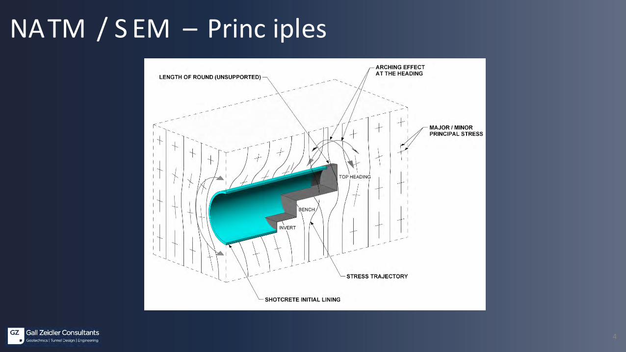
• NATM is a concept that is base d on the understand ing of:• Interac tion of Gro und - C reation of Tunne l Ope ning - Gro und Suppor t While Attempting to:• Mobilize the Optimum Gro und Self -Suppor t
and involve s:• Practical Ex perience and Earth/Engine ering Sciences alike
NATM / SEM
4
NATM / S EM – Princ iples

5
NATM / S EM – Princ iples

6
NATM / S EM – Princ iples
~2D
~2D
~1DTOP HEADING
TOP HEADINGCOMPLETED
BENCH/INVERT
BENCH/INVERTCOMPLETED
EXCAVATION INFLUENCE ZONE
EXCAVATION INFLUENCE ZONE
7
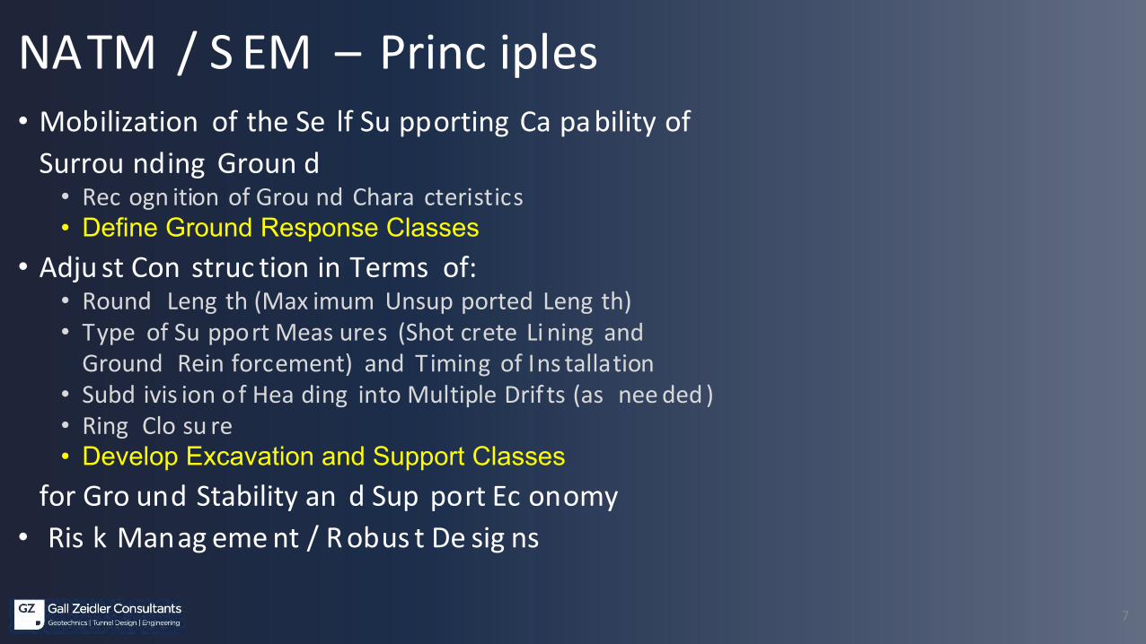
• Mobilization of the Se lf Su pporting Ca pability of Surrou nding Groun d
• Rec ogn ition of Grou nd Chara cteristics• Define Ground Response Classes
• Adju st Con struc tion in Terms of:• Round Leng th (Max imum Unsup ported Leng th) • Type of Su pport Meas ures (Shot crete Li ning and
Ground Rein forcement) and Timing of Ins tallation• Subd ivis ion o f Hea ding into Multiple Drif ts (as nee ded )• Ring Clo su re• Develop Excavation and Support Classes
for Gro und Stability an d Sup port Ec onomy• Ris k Manag eme nt / R obus t De sig ns
NATM / S EM – Princ iples

8
Prototypic al Cross Secti onTUNNEL
CL
ROCK BOLTS/DOWELS STAGGERED
LATTICE GIRDER
PRE-SPILING
90°
TOP HEADING
BENCH
INVERT
THEORETICAL EXCAVATION LINE

9
Prototy pical Longitudinal Exc avation and Support Class (ESC)

10
Prototypic al Longitudinal SectionEL
EVAT
ION
(m)
+580
+620
STATION: 200
EXPECTED STATION:
GROUND RESPONSE CLASS
200+
00
+660
+700
EXCAVATION & SUPPORT CLASS
ADDITIONAL SUPPORT MEASURES
GROUNDWATER
201 202 203 204 205 206 207
PORTAL PORTAL
IV
200+
54
200+
95
201+
52
202+
37
204+
80
202+
80
205+
90
206+
65
207+
10
IVIIIIIIIIIIIIIIIII
RT-MS3 RT-MS3 RT-MB3 RT-QZT2 RT-MB2 RT-MB1 RT-MB2 RT-MB3 RT-MS4
HIGH INFLOW POTENTIAL
DESCRIPTION WEATHERED METASEDIMENTS
WEATHEREDMETABASALT
FRACTUREDQUARTZITE PARTIALLY WEATHERED TO FRESH METABASALT
PRE-SPILING & DRAINAGE PIPESPRE-SPILING PRE-SPILING
WEATHEREDMETABASALT
WEATHERED METASEDIMENTS

11
Regular Cro ss Secti on• Geome try• Dual Li ning Cha racter• Initial Lini ng

12
Regular Cro ss Secti on• Cas t-in-Plac e Conc rete Li ning• Shot crete Fina l L ining• Water Impe rmeable Conc rete Li ning• Sing le Pass Li ning s

13
NATM/SEM – Recent Developments and Range of Applic ations• Grou nd Improveme nt• Shotc rete Material• Urba n Tunneling• Proc ureme nt and Co ntrac tual
Requi reme nts in Desig n a nd Cons truction• Deri va tives : Combi Shel l and La se rShe ll
14
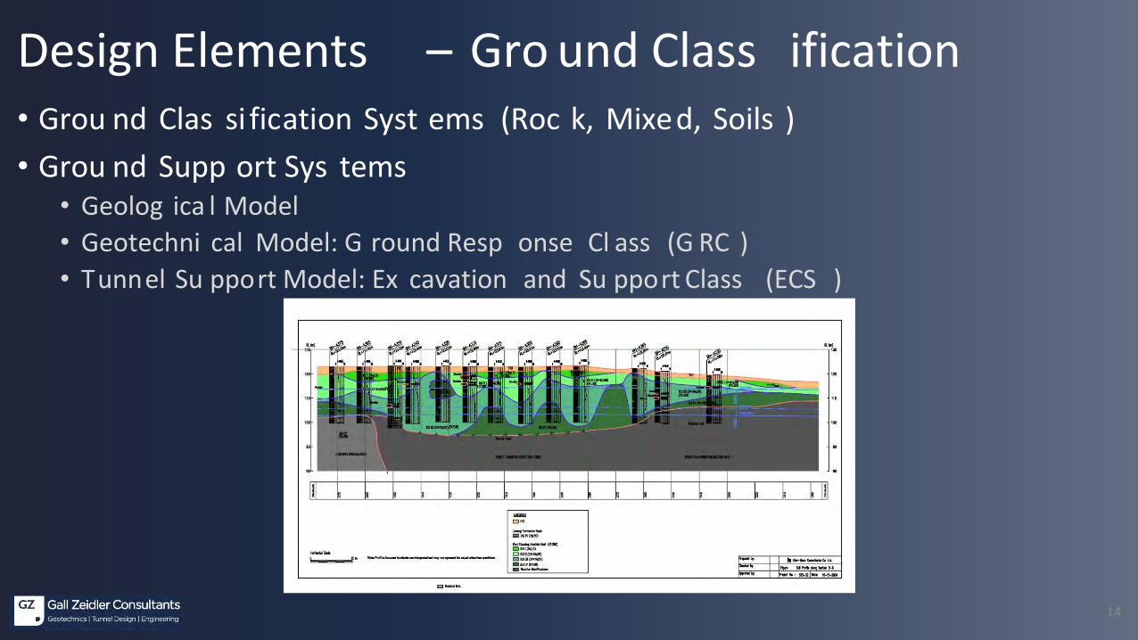
Design Elements – Gro und Class ification• Grou nd Clas si fication Syst ems (Roc k, Mixed, Soils )• Grou nd Supp ort Sys tems
• Geolog ica l Model• Geotechni cal Model: G round Resp onse Cl ass (G RC )• Tunnel Su pport Model: Ex cavation and Su pport Class (ECS )
15
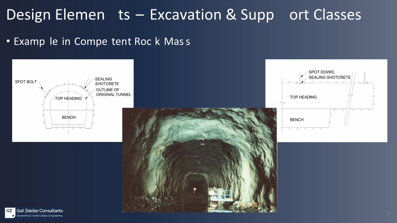
Design Elemen ts – Excavation & Supp ort Classes• Examp le in Compe tent Roc k Mas s
16
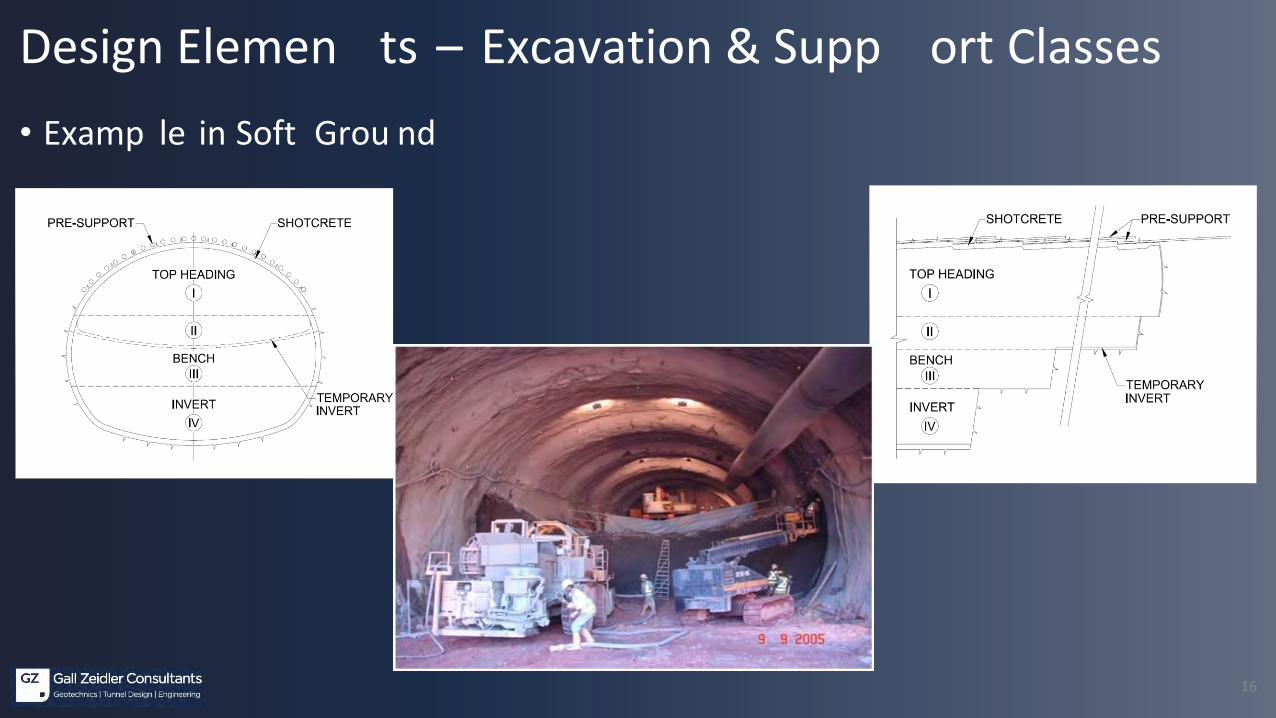
• Examp le in Soft Grou nd
Design Elemen ts – Excavation & Supp ort Classes
17
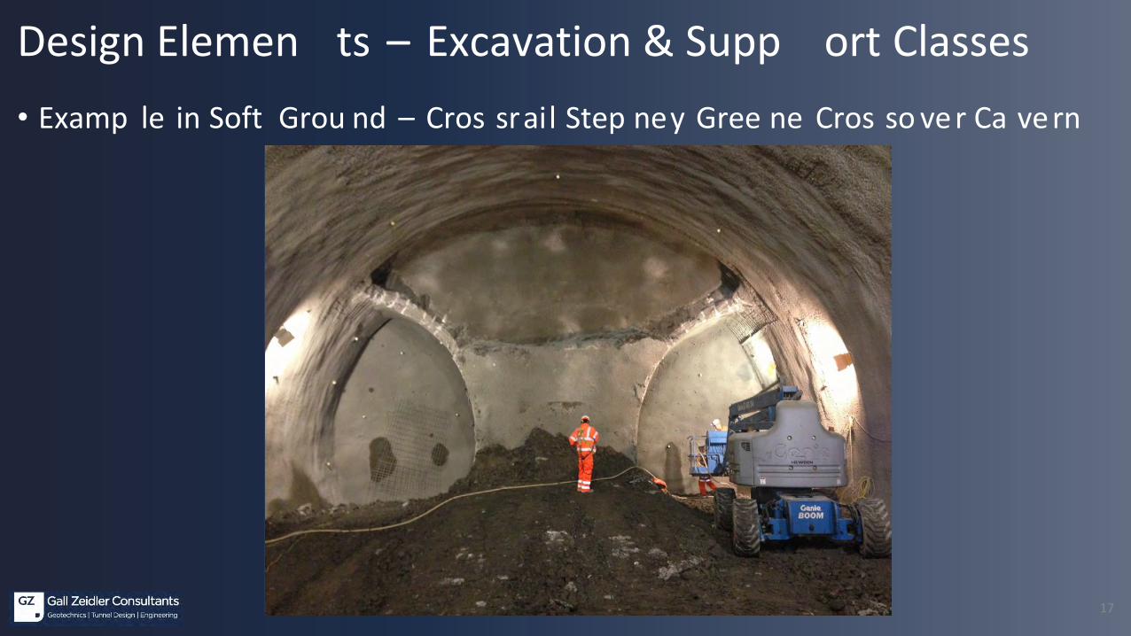
• Examp le in Soft Grou nd – Cros srail Step ney Gree ne Cros so ver Ca vern
Design Elemen ts – Excavation & Supp ort Classes

18
• Examp le in Soft Grou nd – Cros srail Bond St. Stati on SEM Enl arge men t
Design Elemen ts – Excavation & Supp ort Classes
19
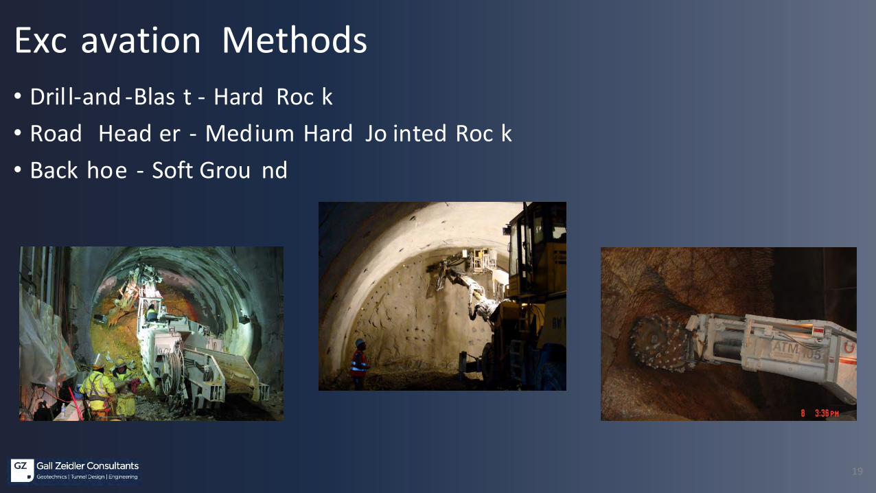
Exc avation Methods• Dril l-and -Blas t - Hard Roc k• Road Head er - Medium Hard Jo inted Roc k• Back hoe - Soft Grou nd

20
Shotcrete• Ef fects of Shotc rete
• Fl ashcrete• Fa ce Su pport• Intial Sh otcrete Lini ng• Temporary Su pport Walls
21
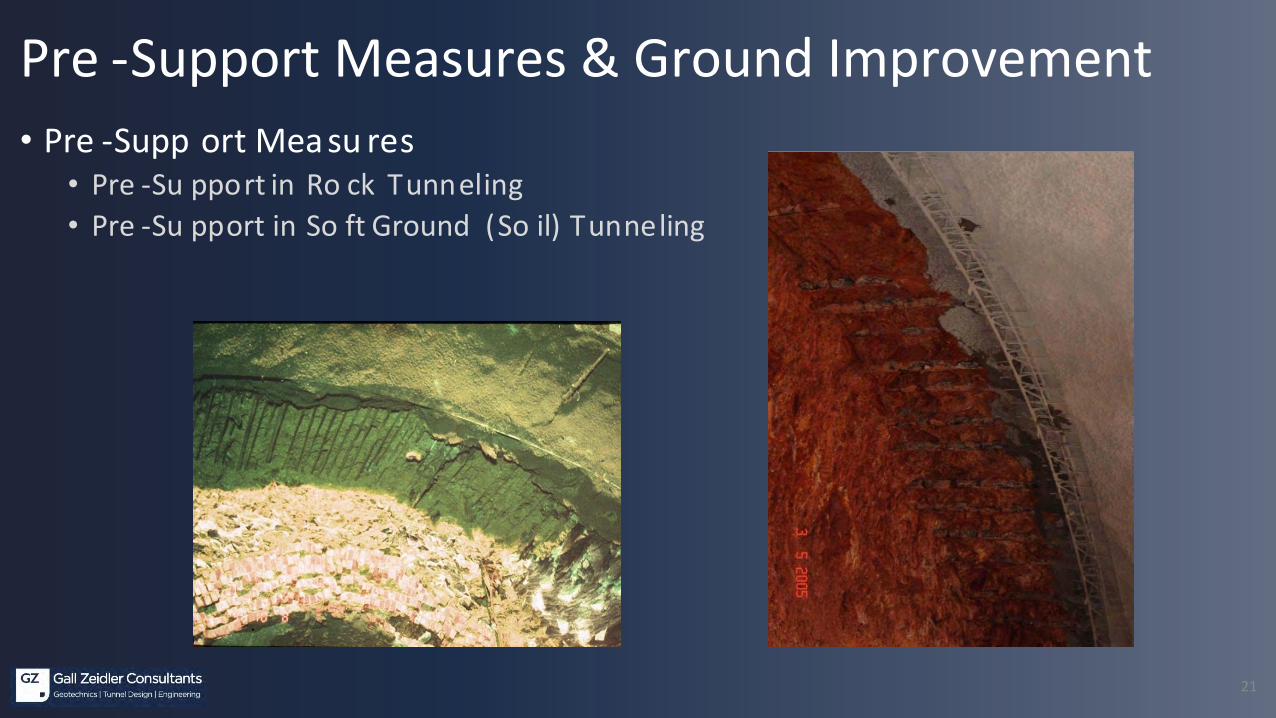
Pre -Support Measures & Ground Improvement• Pre -Supp ort Mea su res
• Pre -Su pport in Ro ck Tunneling• Pre -Su pport in So ft Ground (So il) Tunneling

22
Pre -Support Measures & Groun d Im provement• Pre -Supp ort Mea su res
• Gr outed Pi pe Arch Can opy• Face Dowe ling
23
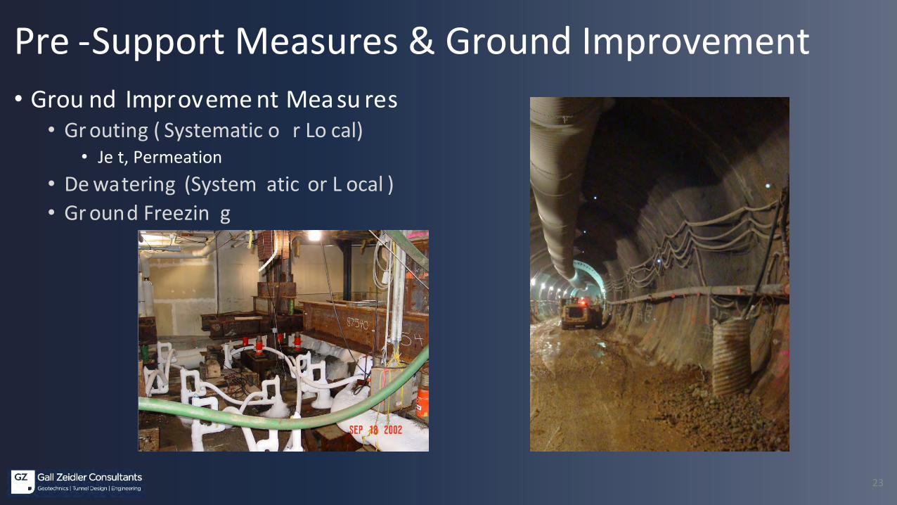
Pre -Support Measures & Ground Improvement• Grou nd Improveme nt Mea su res
• Gr outing ( Systematic o r Lo cal)• Je t, Permeation
• De watering (System atic or L ocal )• Gr ound Freezin g

24
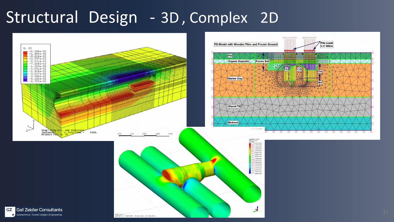
Structural Design• Use Gro und-St ructure Interacti on Models to ac count for St ress and De formation in the
Sur rounding Gr ound
• Finite Element Methods (sinc e about 1965 in NATM Tunnel D esigns), Finite Difference Methods
• Use of Grou nd Material Co nstitutive Models to Desc ribe De formation, Y ielding and Pos t-yielding Beha vior
• Mohr-Coulomb• Druck er-Prager• Hoek and B rown• Others
• 2-D for Line St ructures a nd 3-D M odeling for J unctions, Intersec tions, Cav erns or Appro ximations
• “Avoid” Embedd ed Frame Modeling

25
Structural Design 2D

26
Structural Design• Ground Stresses and Deformations / Surface Settlements• Lining Design – Initial and Final• Design of Rock Reinforcement
27
Structural Design - 3D , Complex 2D

28
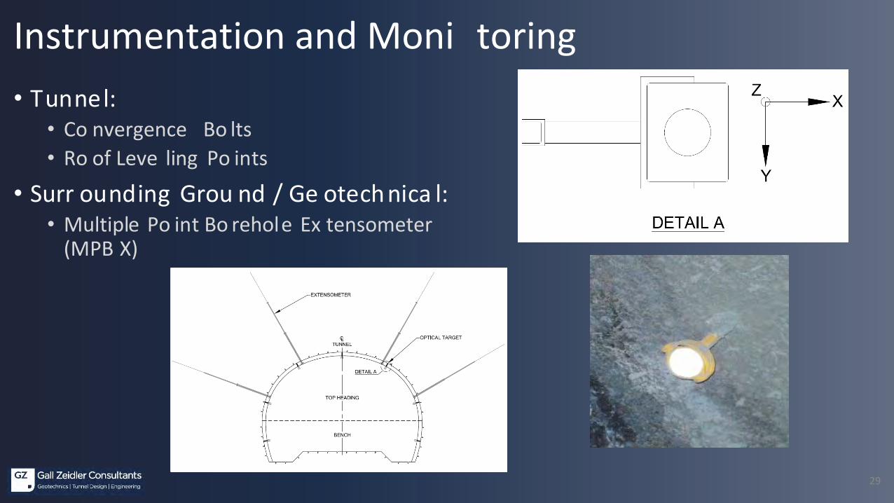
• Tunne l:• C onvergence Bolts• R oof Lev eling Point s
• Sho tcrete and Gro und Loa d Cell s
• Surr ound ing Gro und / Geotec hnic al:• Multiple Point Borehole Ex tens ometer (MPBX )• Inc linometer• Piez ometer
• Surface :• Set tlement Point s• Shallow Subs urface Set tlement Point s
• St ructures:• Deformation• Lev eling
• Re al Time, Re motely Monitored and Ev aluated
Instrumentation and Monitoring
29
• Tunnel:• Co nvergence Bo lts• Ro of Leve ling Po ints
• Surr ounding Grou nd / Ge otechnica l:• Multiple Po int Bo rehole Ex tensometer
(MPB X)
Instrumentation and Moni toring
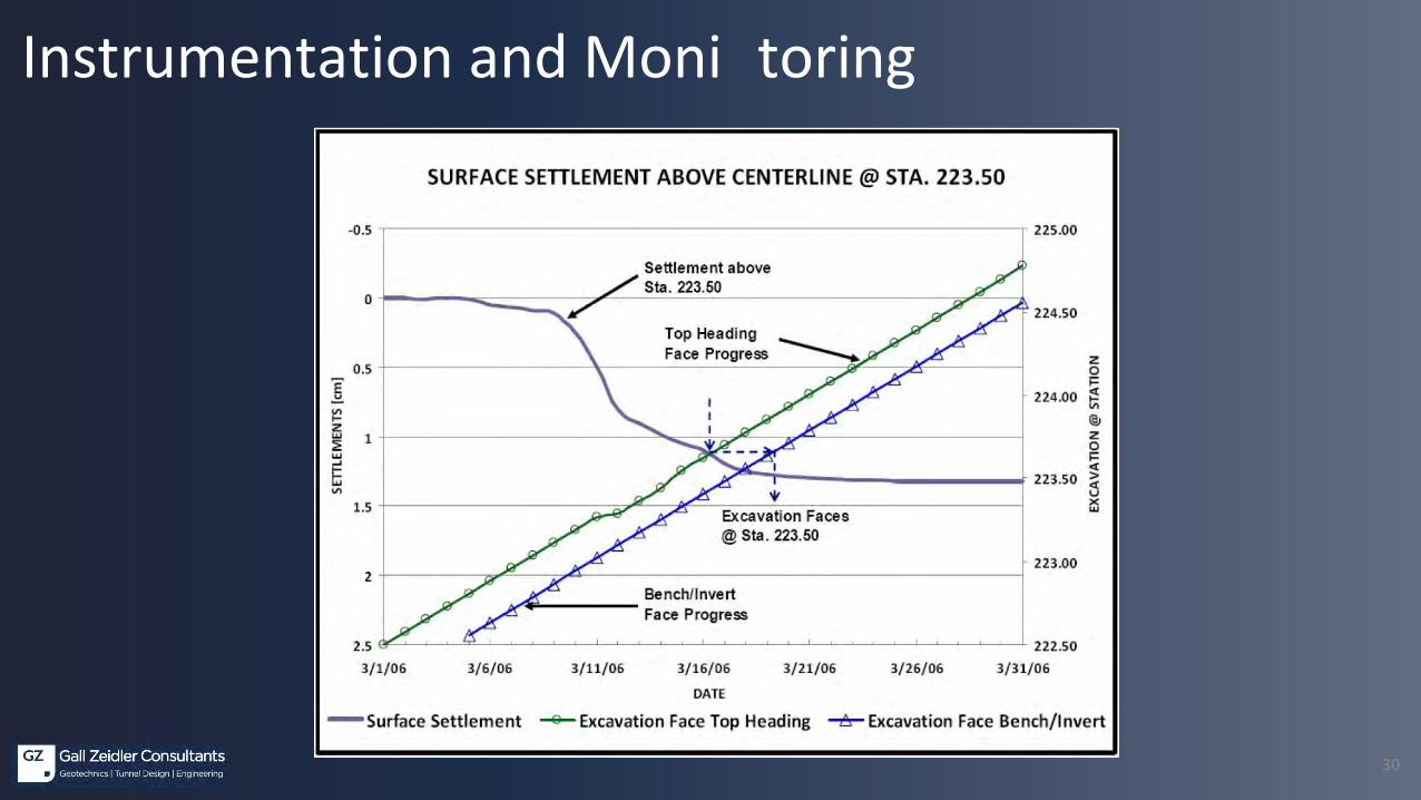
30
Instrumentation and Moni toring

31
Instrumentation and Moni toring

32
Instrumentation and Moni toring

33
Instrumentation and Moni toring
34
Contractual Aspects, Risk Management• Des ign and Ri sk Man ag eme nt by Des ign
• Ex perie nced De sig ner
• GDR and GBR• Grou nd and Su pport Cla ss ifica tion
• From Ground beha vior to Su pport requirements• De velo p Distributions of S upport Cl asses along Tunnel Alignment
• Unit Pric ing to Su it Clas si fication of Grou nd and Su pport• Su pport Classe s• Loca l Su pport Measures• Pre -Su pport Measu res• Gr ound Improvement Measu res

35
• Cont ractor Pre -qualifica tion• Stric t Qua lity Cont rol Re quiremen ts: Expe rienced NA TM Pers onnel -
Each Shif t• CM Repr es entation• Ins trumenta tion• Geol og ic Map ping• Requ ired Exca va tion and Sup port Shee t (RES S): Dail y• Formal Risk Asses smen t (multiple levels )• Impleme tation of the "Rig ht Supp ort"
Contractual Aspects, Risk Management

36
CASE HIST OR Y:Dulle s Corridor Metrorail Projec t; Vien na, VA

37
Route 123 Overpass
Courtyard by Marriott
Tunnel Alignment
Inte
rnat
ion
alD
rive
Tunnel Alignment & Adjacent Str uctures
38
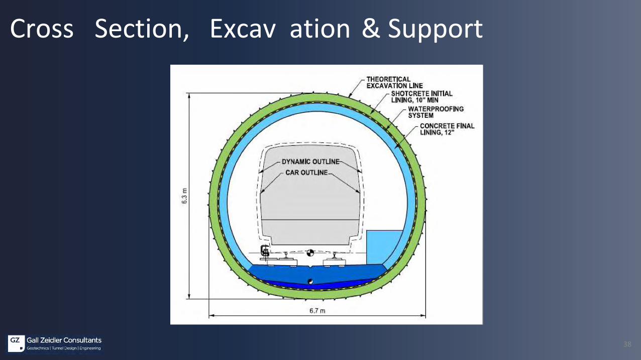
Cross Section, Excav ation & Support

39
Gro und Conditions• Cap of an cient Coa stal Plai n se dimen ts
• Ba nds of cl ay with sil ty sands, gravels, and cob bles
• Res idua l so ils and so il-like dec ompos ed rock
• Fi ne sandy si lts, cla ys, an d sil ty fine sands• Deco mpos ed rock
• So il-like with highe r streng th• Grou ndwater
• Invert level at P ortal locatio ns• Tunnel sprin g line at mid-point of tunnel
alignment

40
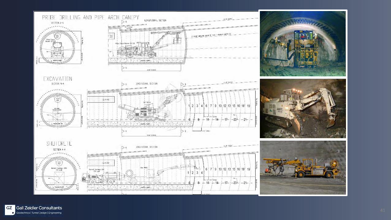
• Use of Steel Grouted Pipe Arch Ca nopy Pre -Suppo rt due to Sof t Ground and Shal low Ov erburden
• Grad ual Incre ase in Tunnel Si ze to Allow for Su bse quent Pi pe Dri lling Re su lted in a Sa w Tooth Ef fect
• Excav ation: Typical Co nventional Method Sequ ence w ith two 3-foot Top He ading Ro unds, Follow ed by a s ingle 6-foot B ench/Inve rt Ro und
Excav ation and Suppo rt
41
42
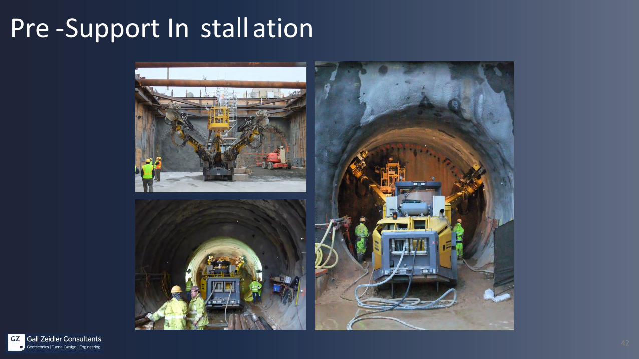
Pre -Support In stall ation
43
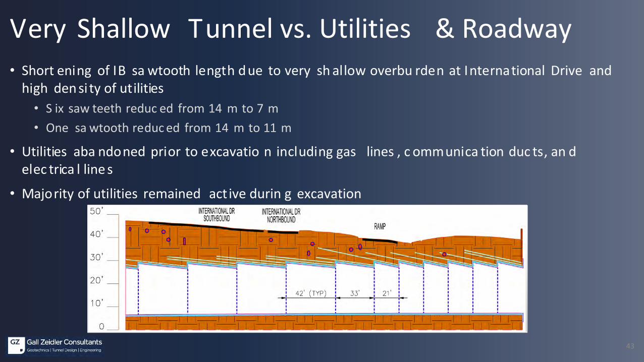
Very Shallow Tunnel vs. Utilities & Roadway• Short ening of IB sa wtooth length d ue to very sh allow overbu rden at International Drive and
high den si ty of utilities• S ix saw teeth reduc ed from 14 m to 7 m• One sa wtooth reduc ed from 14 m to 11 m
• Utilities aba ndoned prior to excavatio n including gas lines , c ommunica tion duc ts, an d elec trica l line s
• Majority of utilities remained act ive durin g excavation

44
Instrumentation & Monitoring• Surfa ce Monitoring
• Threshol d levels• Co ntinge ncy plan in place• An gular distortion measurements
Description Level 1 Level 2
Ground surface settlements
(1st tunnel excavation)
3/4-inch 1-1/4-inch
Ground surface settlements
(1st + 2nd tunnel excavation)
1-0-inch 1-1/2-inch
Horizontal ground movement at tunnel
elevation (at 25 feet distance from tunnel)
1/8-inch 1/8-inch
Tunnel roof settlement 1/2-inch 3/4-inch
Horizontal movement of tunnel sidewalls 1/3-inch 1/2-inch
Maximum utility settlement and
slope of settlement trough
1-0-inch
1/250
1-1/2-inch
1/200
Maximum bridge foundation settlement 1/4-inch 1/2-inch
Maximum surface settlement trough of
road surfaces
1-0-inch 1-1/2-inch
45
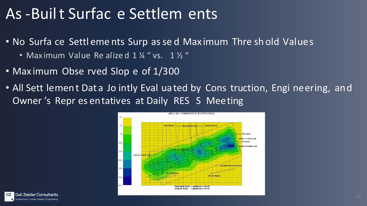
• No Surfa ce Settl eme nts Surp as se d Max imum Thre sh old Values• Max imum Value Re alize d 1 ¼ “ vs. 1 ½ “
• Max imum Obse rved Slop e of 1/300• All Sett lemen t Dat a Jo intly Eval uated by Cons truction, Engi neering, and
Owner ’s Repr es entatives at Daily RES S Meeting
As -Buil t Surfac e Settlem ents

46
As -built Surface Settlem ents

47
Final Lin ing ( CIP) – Ready For In stall ations
ASCE Automation AwardNCE International Tunneling Award Nomination in Category < $ 100 million
48
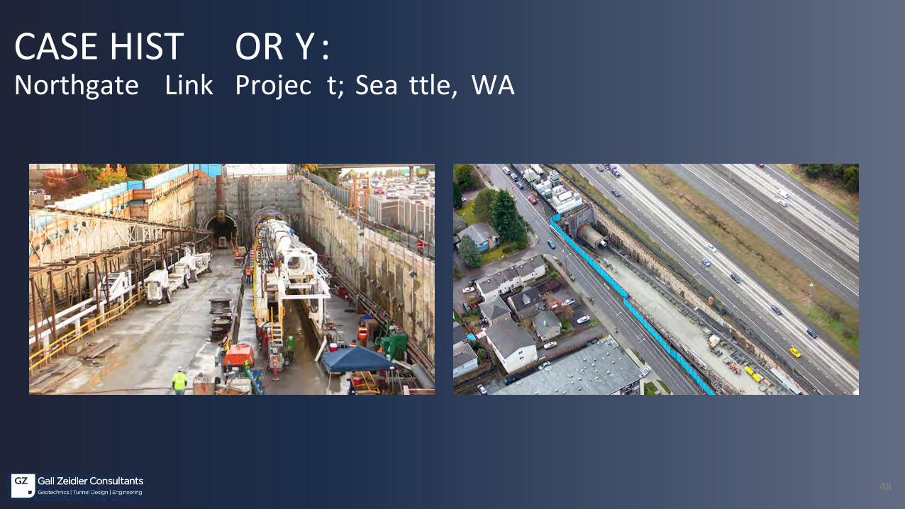
CASE HIST OR Y:Northgate Link Projec t; Sea ttle, WA
49
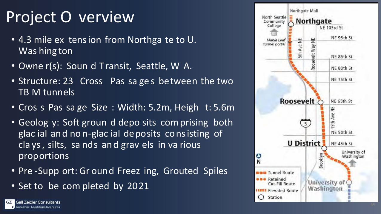
Project O verview• 4.3 mile ex tens ion from Northga te to U.
Was hing ton• Owne r(s): Soun d Transit, Seattle, W A.• Structure: 23 Cross Pas sa ge s between the two
TB M tunnels• Cros s Pas sa ge Size : Width: 5.2m, Heigh t: 5.6m• Geolog y: Soft groun d depo sits com prising both
glac ial and no n-glac ial deposits cons isting of cla ys , silts, sa nds and grav els in va rious proportions
• Pre -Supp ort: Gr ound Freez ing, Grouted Spiles• Set to be com pleted by 2021
50
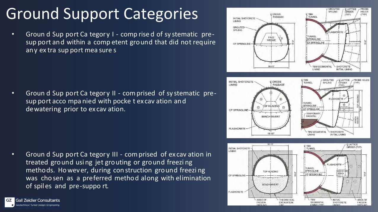
Ground Support Categories• Groun d Sup port Ca tegory I - comp rise d of sy stematic pre-
sup port and within a comp etent ground that did not require any ex tra sup port mea sure s
• Groun d Sup port Ca tegory II - com prised of sy stematic pre-sup port acco mpa nied with pocke t ex cav ation and dewatering prior to ex cav ation.
• Groun d Sup port Ca tegory III - com prised of ex cav ation in treated ground usi ng jet grouting or ground freezi ng methods. Ho wever, during con struction ground freezi ng was cho sen as a preferred method along with elimination of spil es and pre-suppo rt.
51
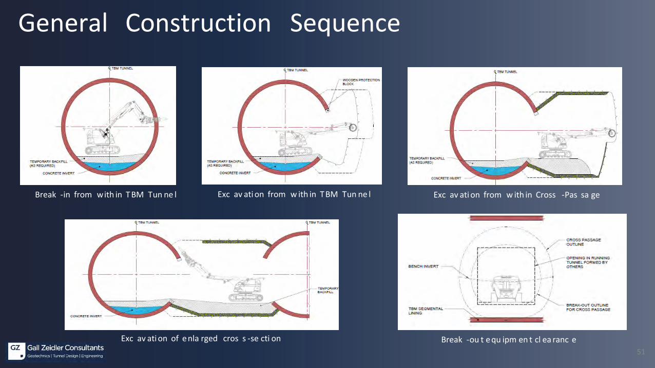
Break -in from with in TBM Tun ne l Exc av ati on from w ith in TBM Tun ne l Exc av ati on from w ith in Cross -Pas sa ge
Break -ou t equ ipm en t cl ea ranc eExc av ati on of enla rged cros s -se cti on
General Construction Sequence

52
Cross Passage Ex cavat ion and Support Installation
Breaking-In the Segment and Excavation of 1st round
Typical Top heading and Bench Excavation
Breaking-out the Segment

53
• Free zin g the groun d to provide stabl e face during ex cava tion• 11 out of 23 cross pa ssages were ex cavated usin g ground freezi ng• Two gr ound freezi ng methods were ado pted – ground freezi ng fr om the surface
and ground freezi ng fr om insid e the TBM tunnel
Typical s chemati cs of ground freezi ng from the surface and Ins ide the tunnel
Ground Improvement - Ground Freezing
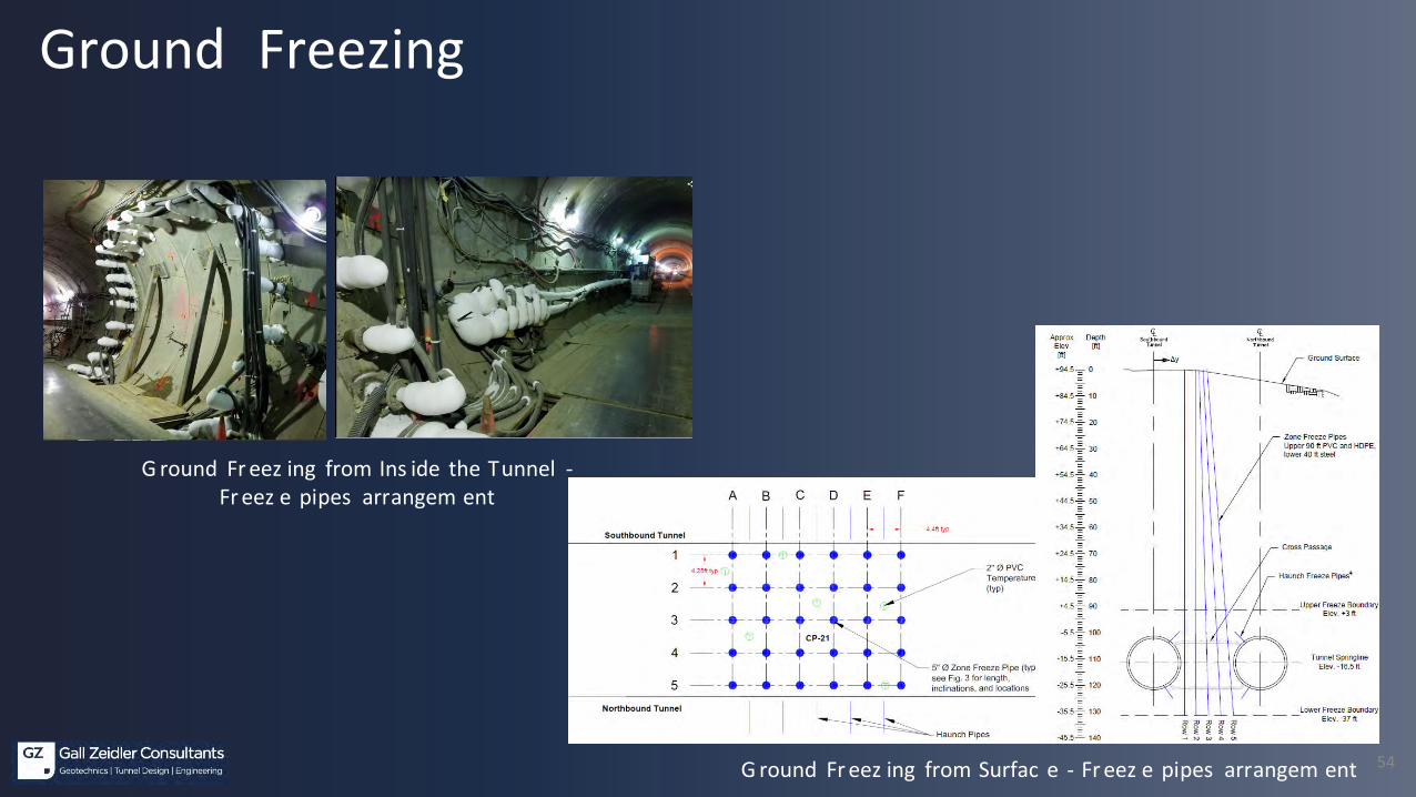
54G round Fr eez ing from Surfac e - Fr eez e pipes arrangem ent
G round Fr eez ing from Ins ide the Tunnel -Fr eez e pipes arrangem ent
Ground Freezing

55
CASE HIST OR YCaldecott 4th Bore Tunnel (O akland, CA)
56
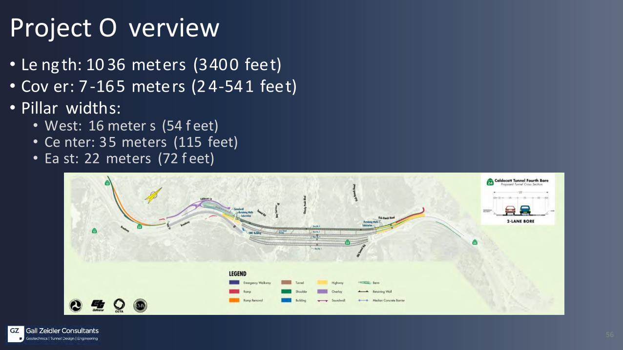
• Le ng th: 10 36 meters (3400 feet)• Cov er: 7 -165 meters (2 4-541 feet)• Pillar widths:
• West: 16 meter s (54 f eet)• Ce nter: 35 meters (115 feet)• Ea st: 22 meters (72 f eet)
Project O verview
57
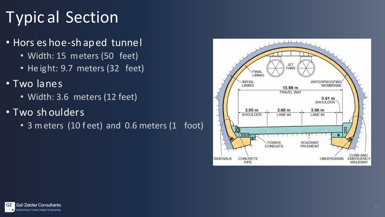
• Hors es hoe-sh aped tunnel• Width: 15 meters (50 feet)• He ight: 9.7 meters (32 feet)
• Two lanes• Width: 3.6 meters (12 feet)
• Two sh oulders• 3 m eters (10 f eet) and 0.6 meters (1 foot)
Typic al Section

58
• The four major faults are all inactive and strike to the northwest. Fault contacts defined by lithologic changes and bedding orientation.
• Minor faults, shears, crushed zones also occur along the alignment away from the major fault zones.
• Igneous Dikes also encountered, most frequently in the Claremont Formation.
Geologic Str ucture
Sobrante Formation
Sandstone, Shale
Claremont Formation
Chert, Shale, Sandstone
Orinda Formation
Sandstone, Siltstone, Mudstone, Conglomerate
SOUTHWEST NORTHEAST
FAULT 1
FAULT 2
FAULT 4
FAULT 3
59
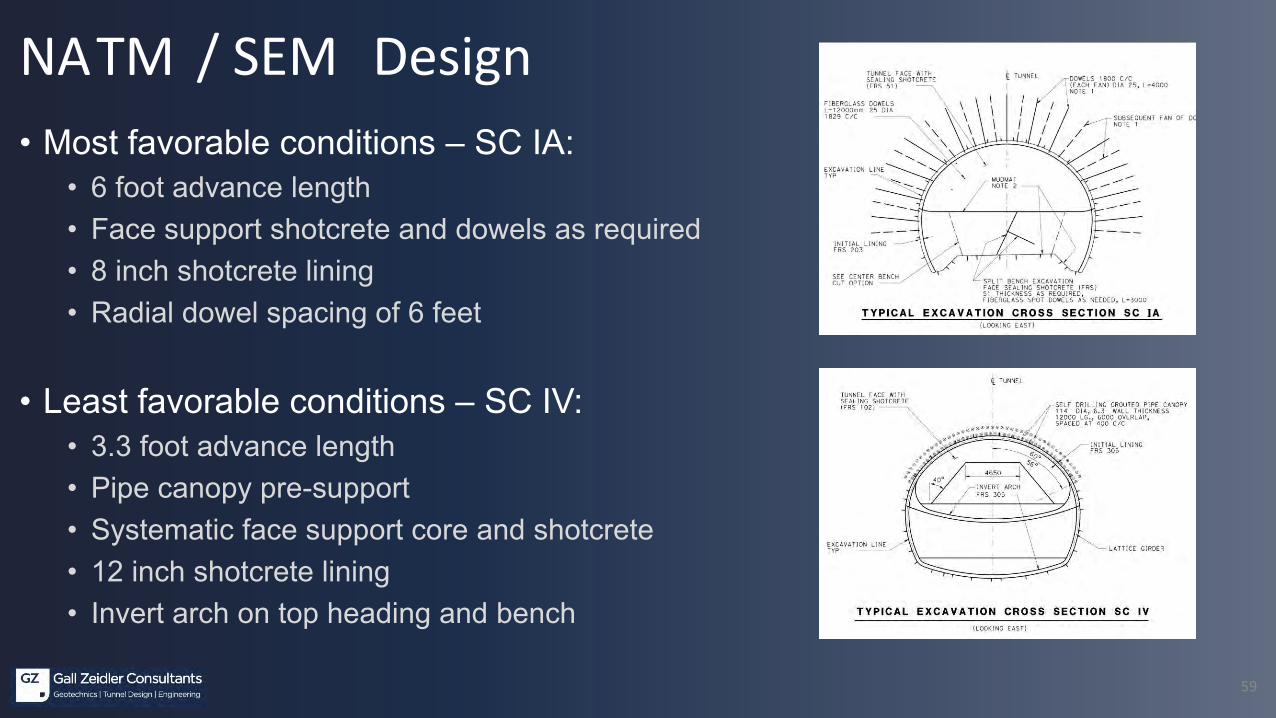
NATM / SEM Design• Most favorable conditions – SC IA:
• 6 foot advance length• Face support shotcrete and dowels as required• 8 inch shotcrete lining• Radial dowel spacing of 6 feet
• Least favorable conditions – SC IV:• 3.3 foot advance length• Pipe canopy pre-support• Systematic face support core and shotcrete• 12 inch shotcrete lining• Invert arch on top heading and bench

60
• Base line of an ticipated distribution of GC/SC for bidding • Deta iled descriptio n of an ticipated behaviors in G BR• Appli cation criter ia:
• Encountered ground conditions and behaviors , measured lining movemen ts, observ ed lining performance
• Daily m eetings to determine support applicat ion – proposed by Co ntractor, appro ved b y Eng ineer
NATM / SEM Design
61
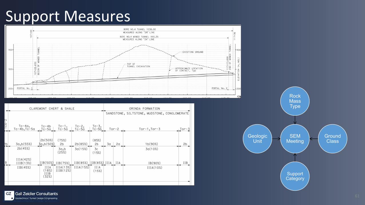
Support Measures
SEM Meeting
Rock Mass Type
Ground Class
Support Category
Geologic Unit

62
Documentation – RESS Sheet

63
Excav ation

64
Rock / Face Dowels and Spiling

65
Benching b y Center Cut in East Head ing
66
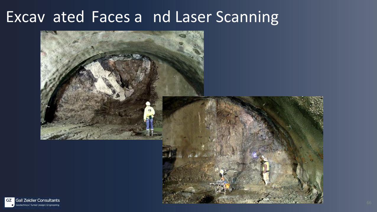
Excav ated Faces a nd Laser Scanning

67
• Fina l lining p roduction sy stem in 3 operations: wate rproofing , reinforce men t and c oncrete
Final Lining

68

69
NATM/SEM – Conclusi ons a nd Outlook• De sig n and Ri sk Man ag eme nt by De sig n (IT A WG 19)
• Co ntractual Frame work
• Ex perience d De sig n, Co nstruction, and Insp ection
• Wide Ran ge of Ap plica tions and Flex ibility• Comp lex Geo metries• Difficult Gro und Con ditions• Urban S ettings
• Outlook• Inc reased Appl ication (Projec ts and i n More Chal lengi ng Condi tions )• Inc reased Experienc e• Refinements i n:
• Ex ploration Tec hniques to Identify Ground C onditions • Ground Improvement Methods• C los e C ooperation of Modeling -Ins trumentation-Ex cavations and Support Adjus tment-As Built C onditions• More Ef ficient Materials Inc luding Shotc rete and Waterproofing
70
QUE ST IONS / DISCUS SION
Top Related