


Languages
Pages
Legal


Multidisciplinary Engineering Senior Design
Project 6218 Soft Tissue “Tensile” Tester Preliminary Design Review
2/24/2006
Project Sponsor: Bausch & Lomb
Team Members:Ryan Schkoda – Team Lead
Christopher Kudla – Lead engineerKristina Schober – Mechanical Engineer
Robert Mc Coy – Electrical Engineer
Team Mentor: Dr. Elizabeth DeBartolo
Kate Gleason College of EngineeringRochester Institute of Technology

Agenda
• Introduction• Theory Overview• Objectives and Specifications• Concept Development• Feasibility• Component Selection & Design• Component & Assembly Test• Plan for Senior Design II

Introduction
• Little is known about material properties of the inner eye.
• Bausch & Lomb requested tensile testing device.
• A less traditional method of gathering material property information as been employed.

Membrane Theory
R
a
R
P
EhR
1 6
9
1 3 3 4 1 3/ / /•Small Deflection Equation
•Where a=span radius, R=indenter radius, h=film thickness
E
KxF
Hooke’s Law
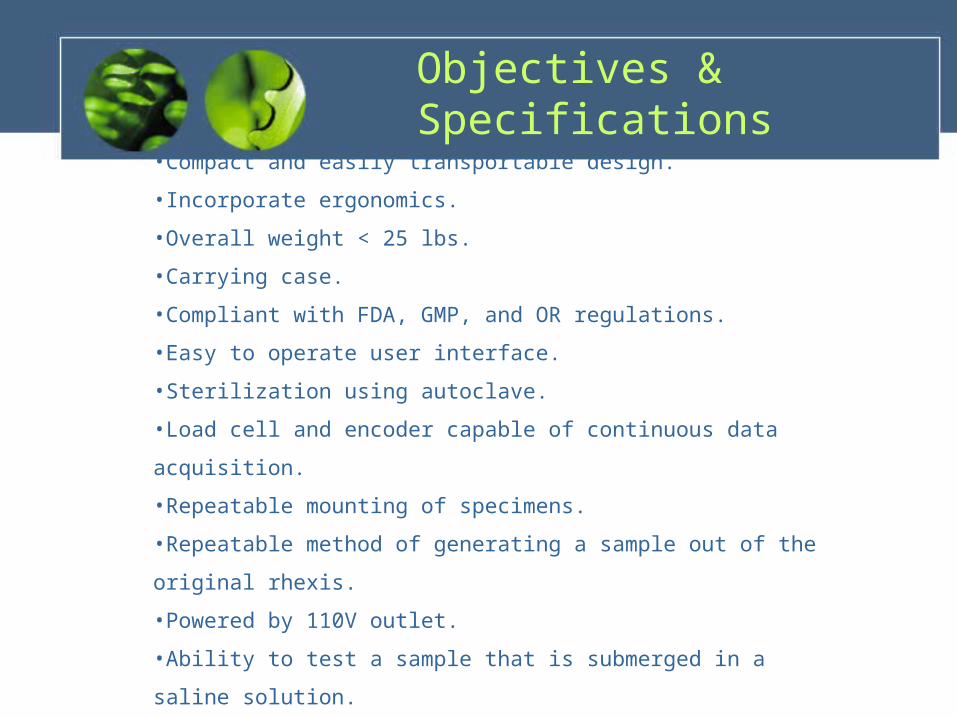
Objectives & Specifications
•Compact and easily transportable design.
•Incorporate ergonomics.
•Overall weight < 25 lbs.
•Carrying case.
•Compliant with FDA, GMP, and OR regulations.
•Easy to operate user interface.
•Sterilization using autoclave.
•Load cell and encoder capable of continuous data acquisition.
•Repeatable mounting of specimens.
•Repeatable method of generating a sample out of the original rhexis.
•Powered by 110V outlet.
•Ability to test a sample that is submerged in a saline solution.
•Cost to be on the order of $5,000.
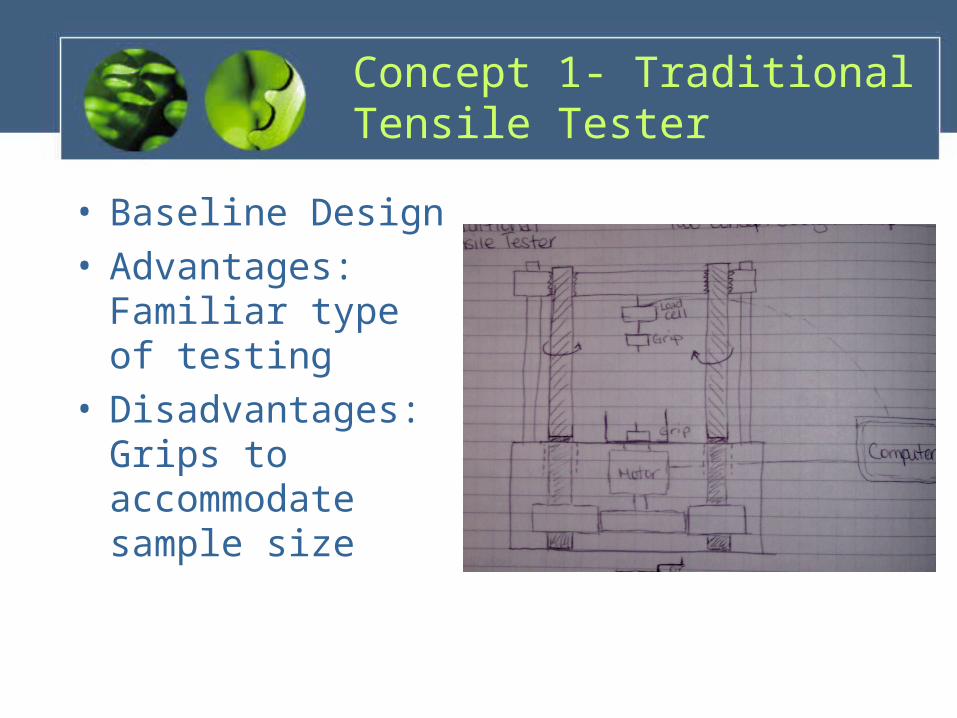
Concept 1- Traditional Tensile Tester
• Baseline Design• Advantages:
Familiar type of testing
• Disadvantages: Grips to accommodate sample size
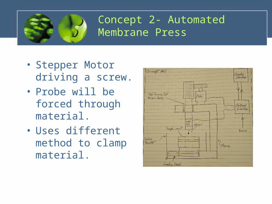
Concept 2- Automated Membrane Press
• Stepper Motor driving a screw.
• Probe will be forced through material.
• Uses different method to clamp material.

Concept 3- Manual Membrane Press
• Similar to Concept 2• Less Expensive• Manual crank
provides more error.

Concept 4 – Automated Membrane Press with Servo
Motor
• Servo Motor with linear stage
• Advantages: Precise operation
• Disadvantages: Need tight tolerances
Feasibility Assessment
• Introduction– Decision making activity– Attributes
• Evaluation of Design Concepts• Pugh Evaluation
– “paired comparison”– Reference concept– Eliminate weak concepts
• Weighted Concept Evaluation– Modified Version – Group Discussion
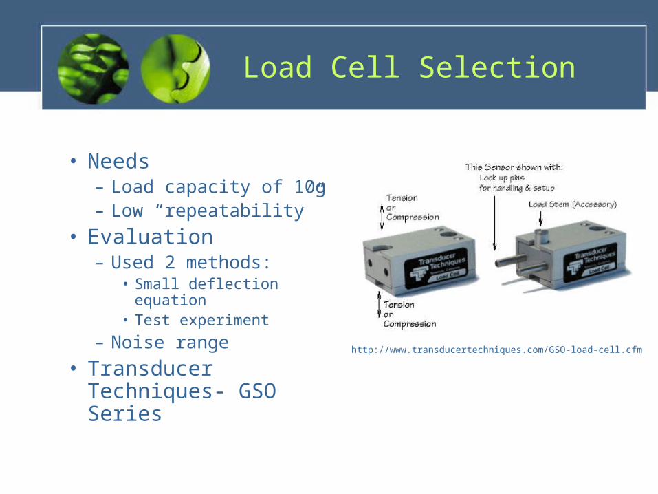
Load Cell Selection
• Needs– Load capacity of 10g– Low “repeatability”
• Evaluation– Used 2 methods:
• Small deflection equation• Test experiment
– Noise range
• Transducer Techniques- GSO Series
http://www.transducertechniques.com/GSO-load-cell.cfm
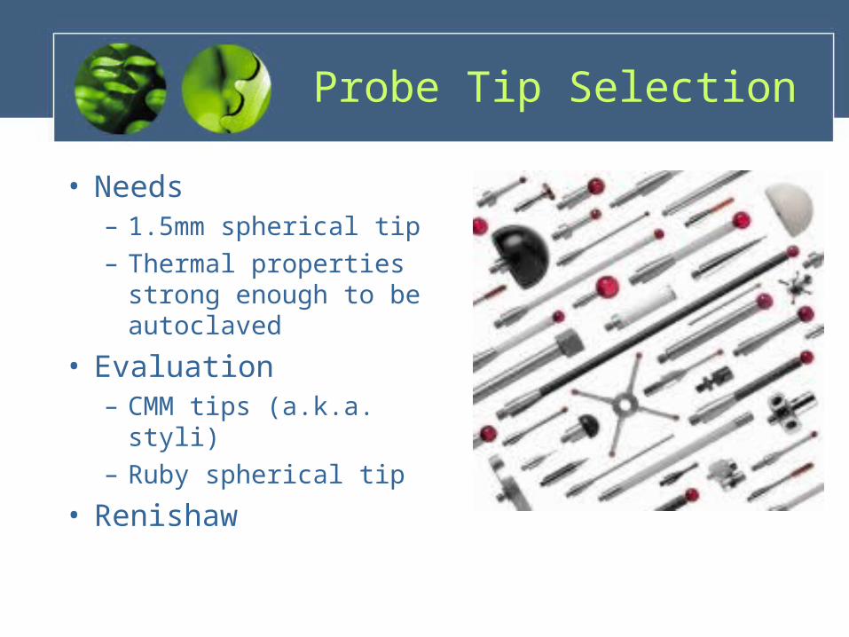
Probe Tip Selection
• Needs– 1.5mm spherical tip– Thermal properties
strong enough to be autoclaved
• Evaluation– CMM tips (a.k.a. styli)– Ruby spherical tip
• Renishaw
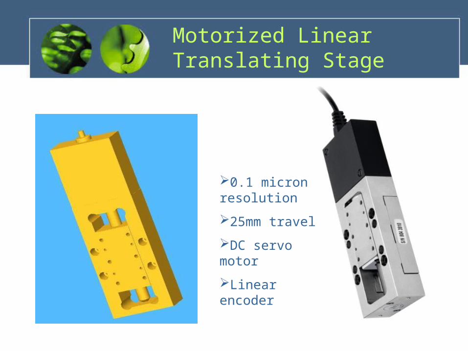
0.1 micron resolution
25mm travel
DC servo motor
Linear encoder
Motorized Linear Translating Stage
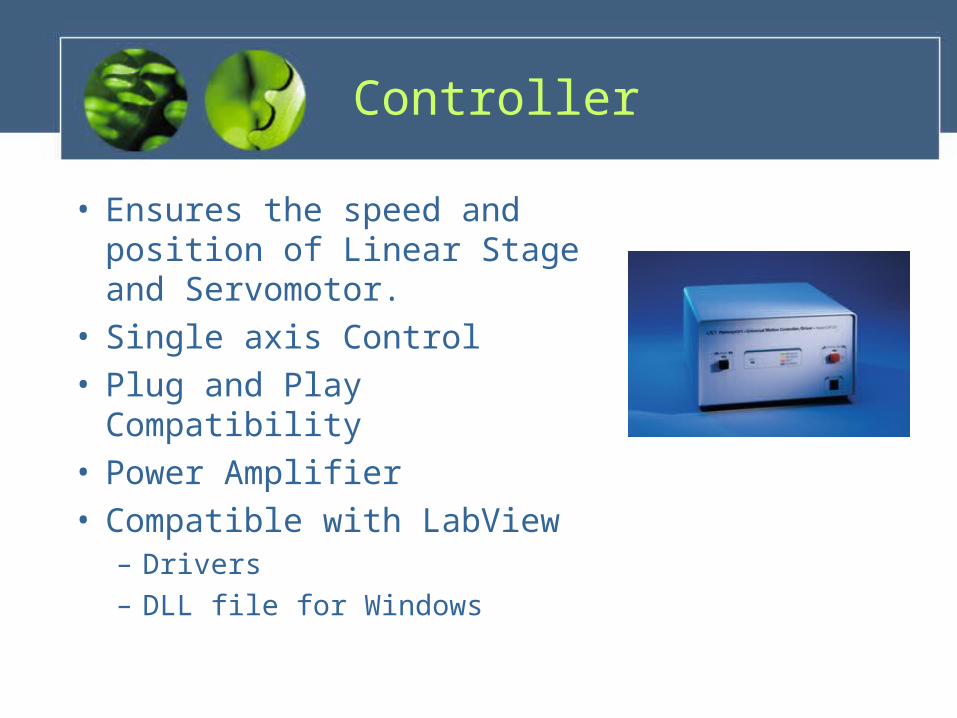
Controller
• Ensures the speed and position of Linear Stage and Servomotor.
• Single axis Control• Plug and Play Compatibility• Power Amplifier• Compatible with LabView
– Drivers– DLL file for Windows

Signal Conditioning and Data Acquisition
• Signal Conditioner– Includes power amplifier for load cell– Increase measurement resolution– Improve signal-to-noise ratios
• Data Acquisition– Outputs data to user interface– Contains an analog to digital
converter– USB capable– LabView® compatible
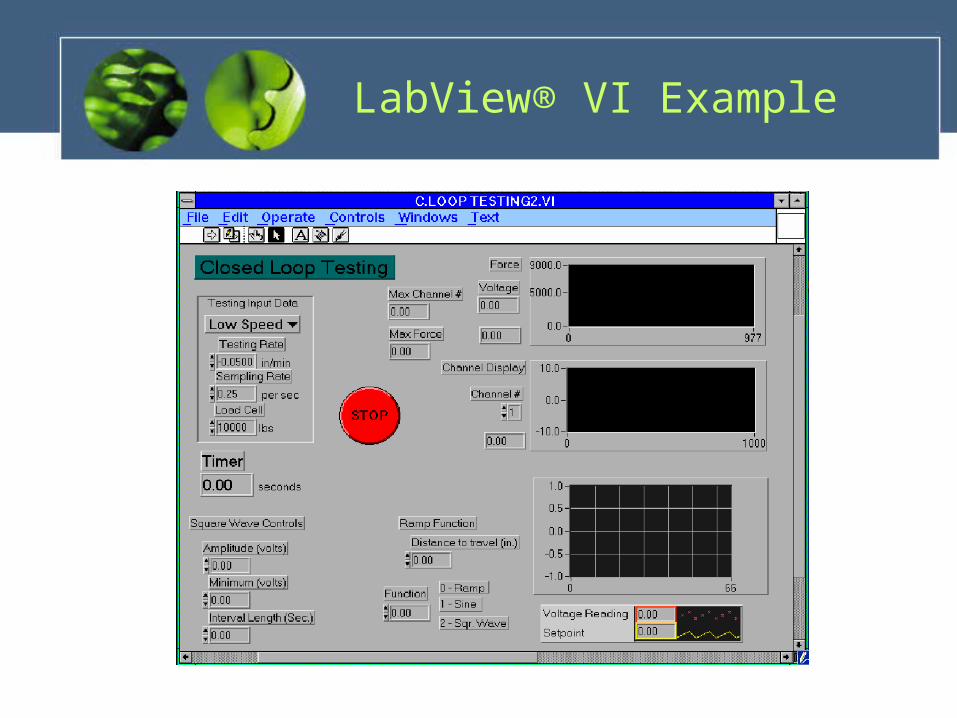
LabView® VI Example

Control and Display
• LabView® interface• USB port link for data input• End user definable• DLL files • LabView® drivers
Load Cell
Signal Conditioner/
Amplifier
USB Data Acquisition /
A/D Converter
Motorized Linear Stage/Encoder
Motion Controller/Driver
LabView
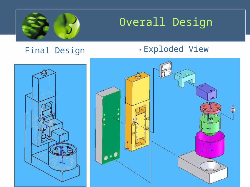
Final Design Exploded View
Overall Design
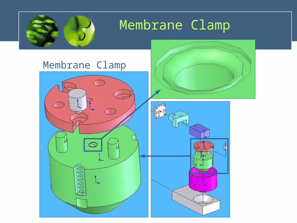
Membrane Clamp
O-Ring GrooveMembrane Clamp
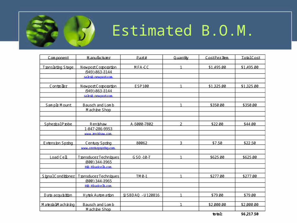
Estimated B.O.M.
Component Manufacturer Part # Quantity Cost Per Item Total Cost
Translating Stage Newport Corporation MFA-CC 1 $1,495.00 $1,495.00(949)-863-3144
Controller Newport Corporation ESP100 1 $1,325.00 $1,325.00(949)-863-3144
Sample Mount Bausch and Lomb 1 $350.00 $350.00Machine Shop
Spherical Probe Renishaw A-5000-7802 2 $22.00 $44.001-847-286-9953www.renishaw.com
Extension Spring Century Spring 80062 3 $7.50 $22.50www.centuryspring.com
Load Cell Transducer Techniques GSO-10-T 1 $625.00 $625.00(800) [email protected]
Signal Conditioner Transducer Techniques TM0-1 1 $277.00 $277.00(800) [email protected]
Data acquisition Hytek Automation iUSBDAQ - U120816 1 $79.00 $79.00
Material/Machining Bausch and Lomb 1 $2,000.00 $2,000.00Machine Shop
total: $6,217.50
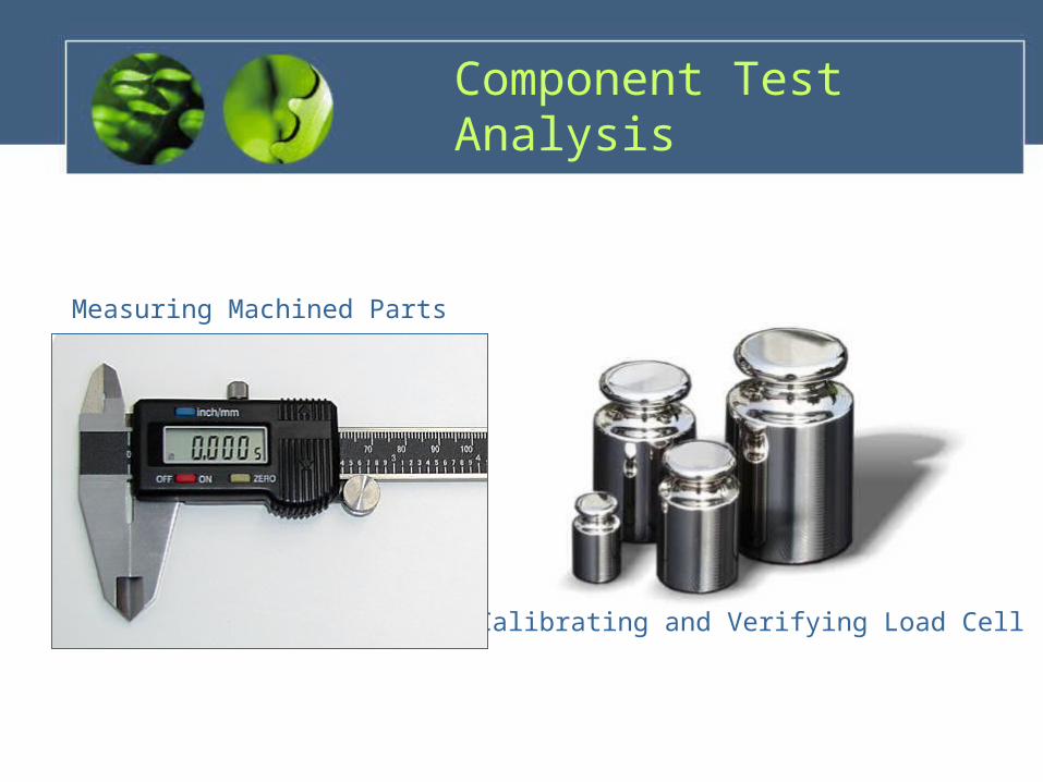
Calibrating and Verifying Load Cell
Measuring Machined Parts
Component Test Analysis
Plan for Senior Design II
• Build Device• Develop Strategy For Interpretation• Troubleshoot• Gage R&R• Further Research of Membrane
Deflection and Simulation

Comments and Questions

Extra Slides - Krissy

Base & Load Arm
Base• Needs
– Stable support linear stage– Cone shaped feature for
water cell and sample mount.

Base & Load Arm
Load Arm• Needs
– Stable to support and align load cell
• Evaluation– Components will be
machined out of stainless steel.
– For ease of machining the base and arm will each have two separate pieces
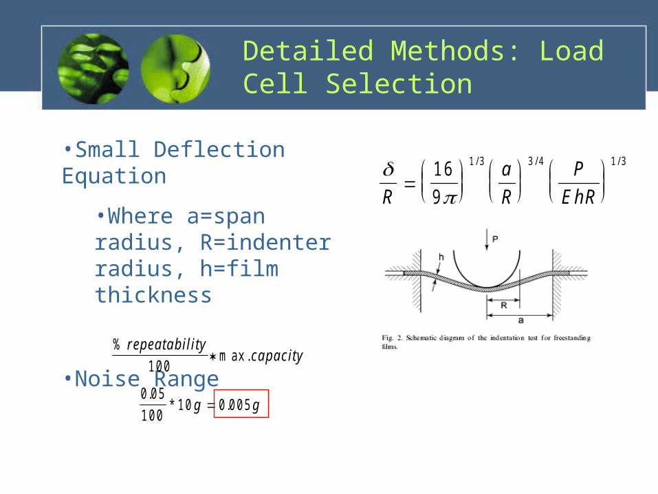
Detailed Methods: Load Cell Selection
R
a
R
P
EhR
1 6
9
1 3 3 4 1 3/ / /•Small Deflection Equation
•Where a=span radius, R=indenter radius, h=film thickness
•Noise Range%
m ax .repea tab ility
capacity1 0 0
0 0 5
1 0 01 0 0 0 0 5
.* .g g
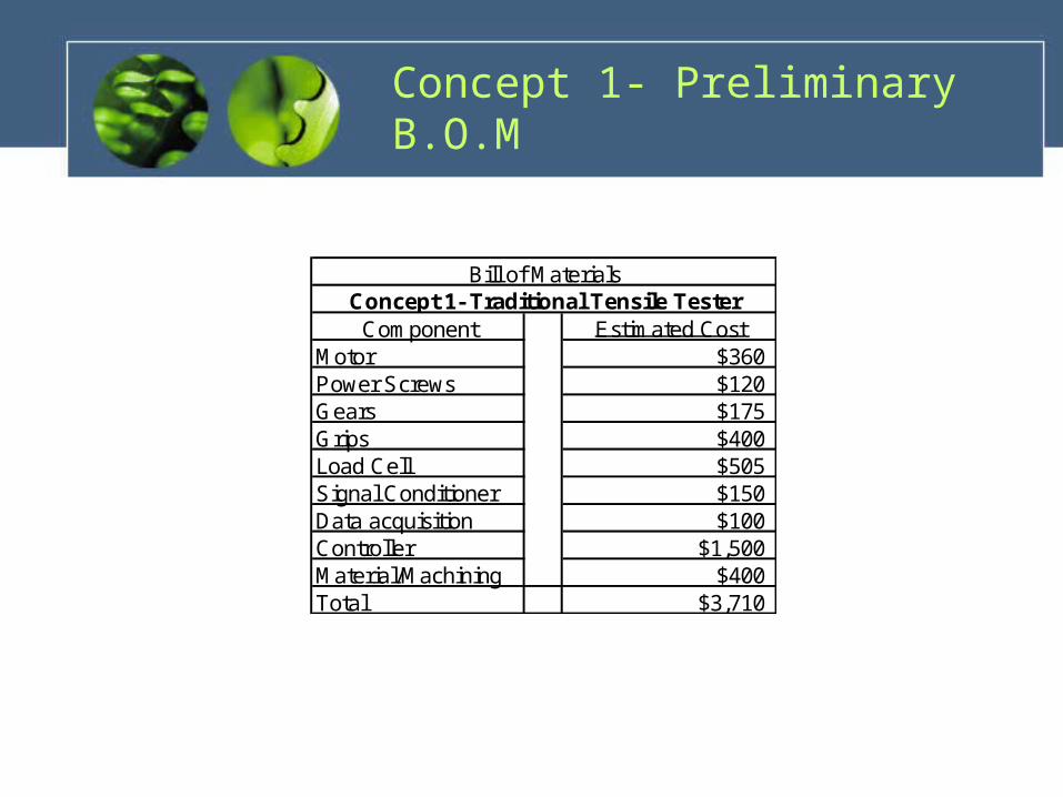
Concept 1- Preliminary B.O.M
Component Estimated CostMotor $360Power Screws $120Gears $175Grips $400Load Cell $505Signal Conditioner $150Data acquisition $100Controller $1,500Material/Machining $400Total $3,710
Concept 1- Traditional Tensile TesterBill of Materials

Concept 2 – Preliminary B.O.M
Component Estimated CostStepper Motor $450.00Power Screw $60Gear $75Sample Mount $350Load Cell $505Signal Conditioner $150Data acquisition $100Controller $1,500Material/Machining $400Total $3,590.00
Concept 2- Automated Membrane PressPreliminary Bill of Materials
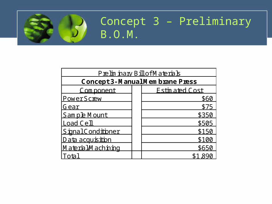
Concept 3 – Preliminary B.O.M.
Component Estimated CostPower Screw $60Gear $75Sample Mount $350Load Cell $505Signal Conditioner $150Data acquisition $100Material/Machining $650Total $1,890
Concept 3- Manual Membrane PressPreliminary Bill of Materials
Load Cell Test
• Follow a “Transducer Checkout Guide” that they provide.
• Use a set of calibrated weights.
• See if Bausch & Lomb could have the component calibrated.
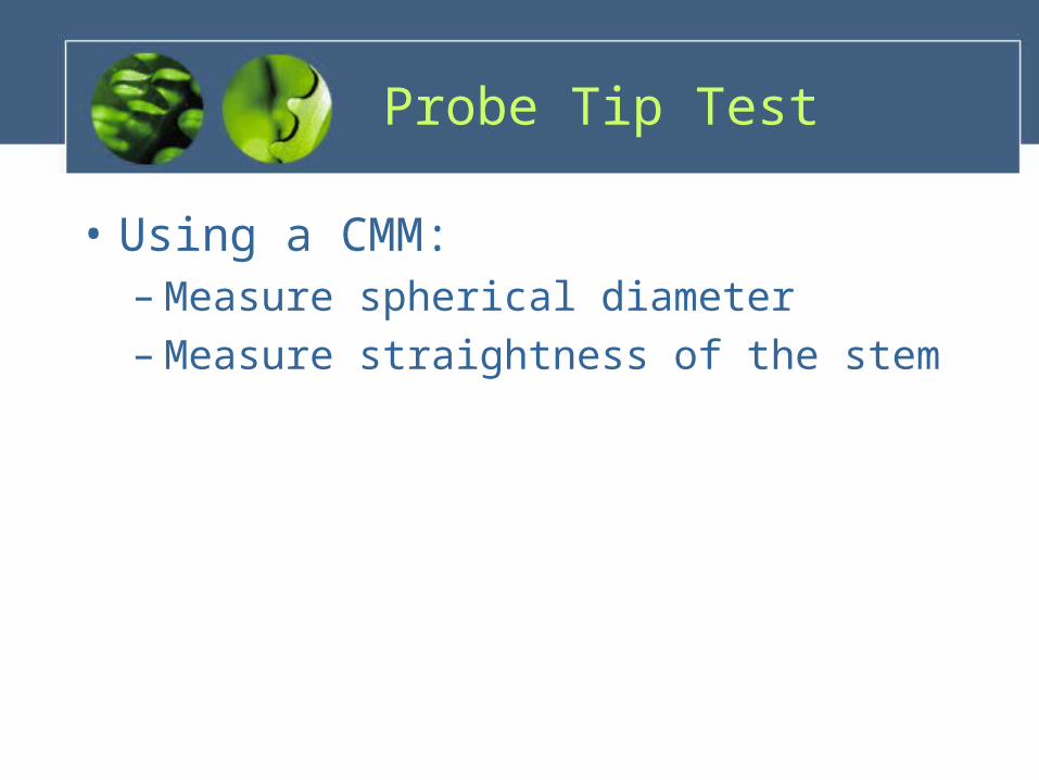
Probe Tip Test
• Using a CMM:– Measure spherical diameter– Measure straightness of the stem

Base & Load Arm Test
• Using a CMM verify that the dimensions match original design.

Extra Slides - Rob

Quality Function Deployment
• What the customer/sponsor wants– Functional Structure– Feasibility Assessment
• Ways to satisfy the customer/sponsor– Project Requirements– Needs Statement
• QFD Chart– Multiple ways to satisfy a need– Important to decision making process

Carrying Case
• Two Cases– Membrane Press– Electrical Components
• Lightweight
• Protects Components
• Transportability
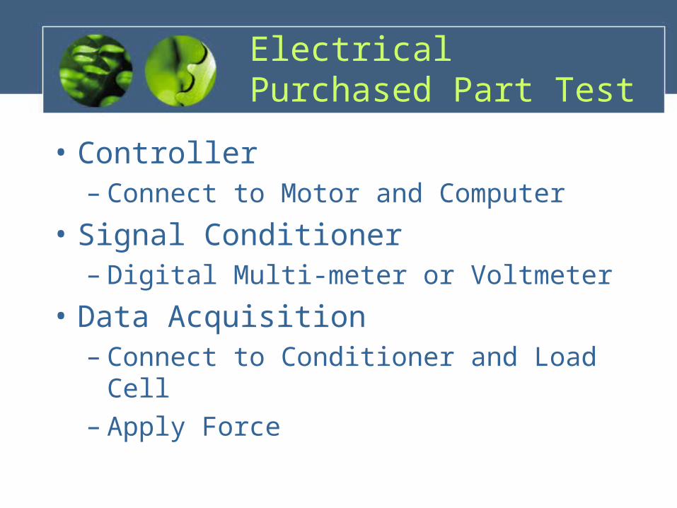
Electrical Purchased Part Test
• Controller– Connect to Motor and Computer
• Signal Conditioner– Digital Multi-meter or Voltmeter
• Data Acquisition– Connect to Conditioner and Load Cell– Apply Force

QFD Chart
110V
inpu
t /
supp
ly
unde
r 25
lbs.
fits
in c
arry
ing
case
OR
com
plia
nt
GM
P c
ompl
iant
FD
A c
ompl
iant
seal
ed o
r dr
y be
arin
gs
min
. cu
stom
par
ts
ther
mal
mas
s <
__
load
cel
l res
olut
ion
± __
reas
onab
le Δ
t
repr
oduc
ible
load
ing
not
relia
nt o
n us
er
use
of s
tand
ardi
zed
load
ing
proc
edur
e
unde
r $5
000
auto
shu
t of
f
use
com
mer
cial
ly a
vaila
ble
cont
rolle
r /
user
inte
rfac
e
disp
lace
men
t re
solu
tion
± __
inco
rpor
ate
abili
ty t
o su
bmer
ge s
ampl
e
Safe Operation X X X X
Ease of Use X X X X X X X
Powered Conveniently X
Export Data X X X
Material Property Data X X X X X X
Accuracy / Precision X X X X X
Regulatory Agency Compliant X X X X X X
Sample Loading X X X X
Test in Saline X
Low Cost X
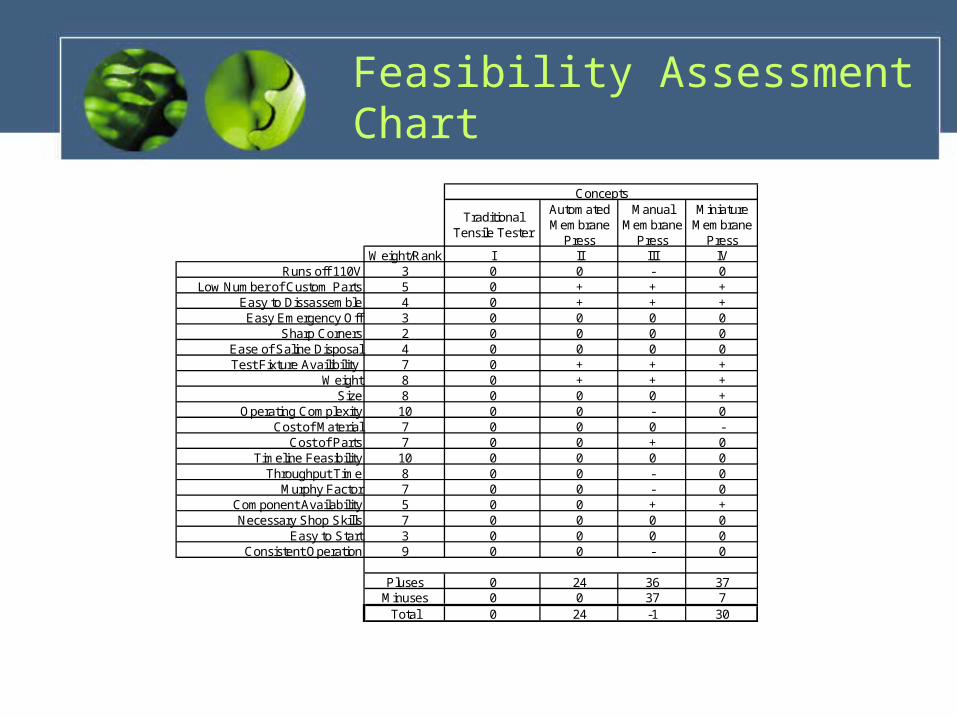
Feasibility Assessment Chart
Traditional Tensile Tester
Automated Membrane
Press
Manual Membrane
Press
Miniature Membrane
PressWeight/Rank I II III IV
Runs off 110V 3 0 0 - 0Low Number of Custom Parts 5 0 + + +
Easy to Dissassemble 4 0 + + +Easy Emergency Off 3 0 0 0 0
Sharp Corners 2 0 0 0 0Ease of Saline Disposal 4 0 0 0 0Test Fixture Availibility 7 0 + + +
Weight 8 0 + + +Size 8 0 0 0 +
Operating Complexity 10 0 0 - 0Cost of Material 7 0 0 0 -
Cost of Parts 7 0 0 + 0Timeline Feasibility 10 0 0 0 0
Throughput Time 8 0 0 - 0Murphy Factor 7 0 0 - 0
Component Availability 5 0 0 + +Necessary Shop Skills 7 0 0 0 0
Easy to Start 3 0 0 0 0Consistent Operation 9 0 0 - 0
Pluses 0 24 36 37Minuses 0 0 37 7
Total 0 24 -1 30
Concepts

Extra Slides - Chris
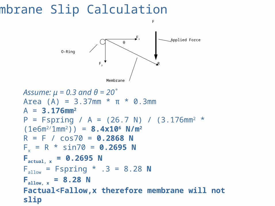
Membrane Slip Calculation
R
Fx
Fy
θ
F
Membrane
Applied Force
O-Ring
Assume: μ = 0.3 and θ = 20˚Area (A) = 3.37mm * π * 0.3mmA = 3.176mm2
P = Fspring / A = (26.7 N) / (3.176mm2 * (1e6m2/1mm2)) = 8.4x10⁶ N/m2
R = F / cos70 = 0.2868 NFx = R * sin70 = 0.2695 N
Factual, x = 0.2695 N
Fallow = Fspring * .3 = 8.28 N
Fallow, x = 8.28 N
Factual<Fallow,x therefore membrane will not slip
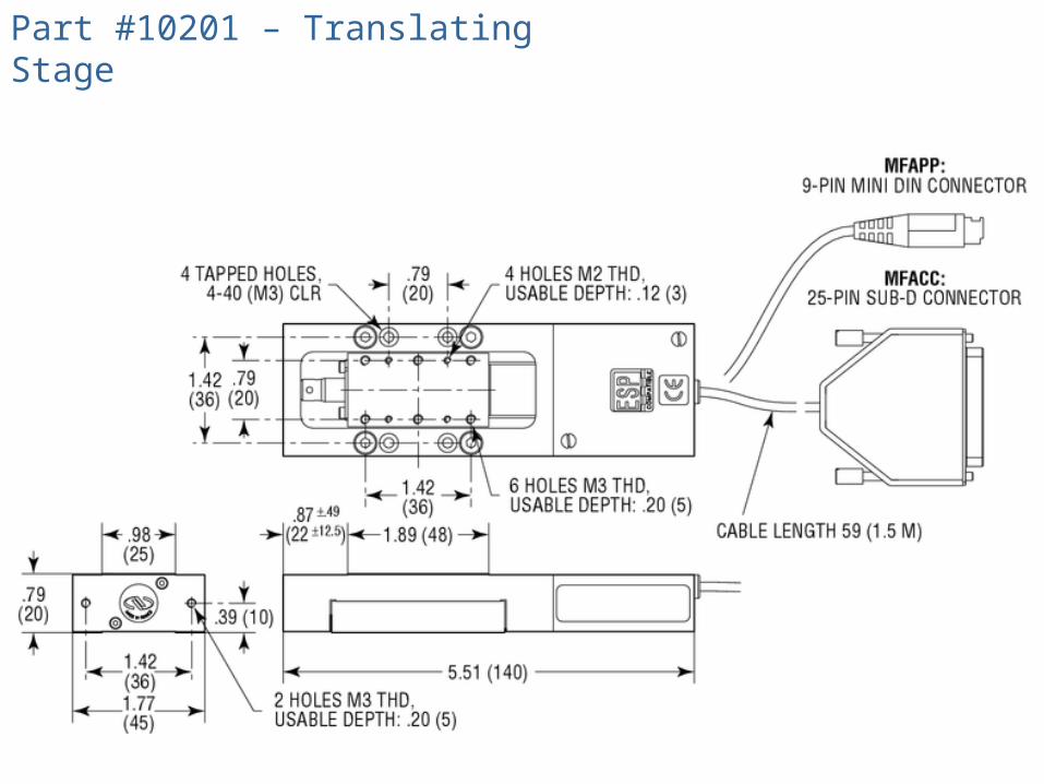
Part #10201 – Translating Stage
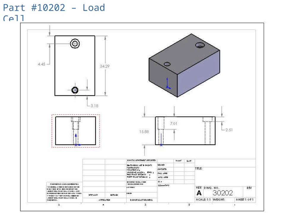
Part #10202 – Load Cell
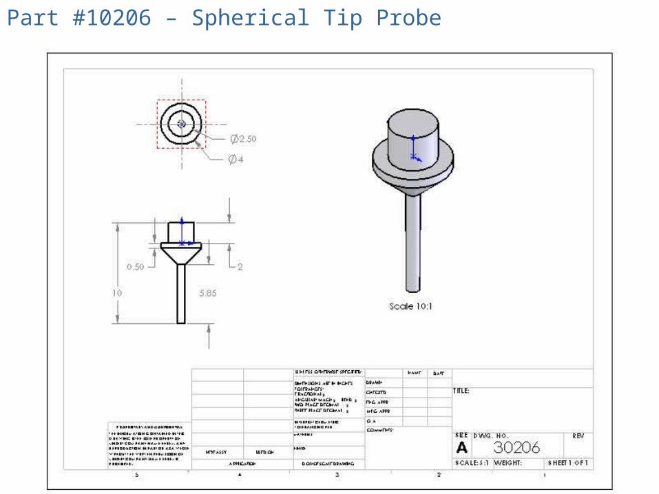
Part #10206 – Spherical Tip Probe

Part #11101 – Base Upper Section
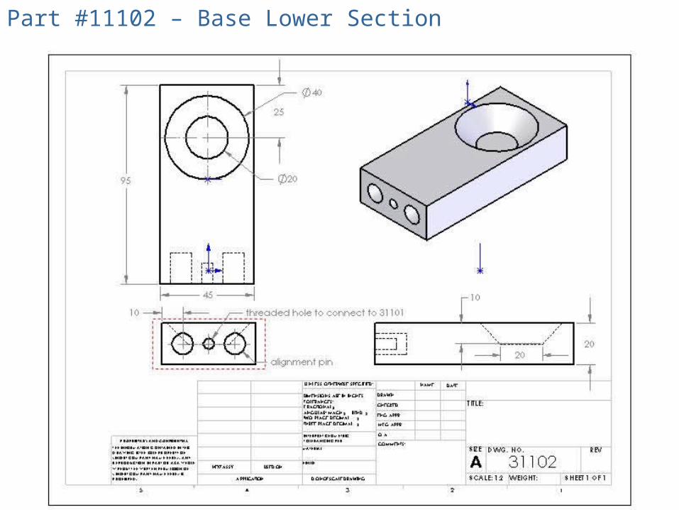
Part #11102 – Base Lower Section
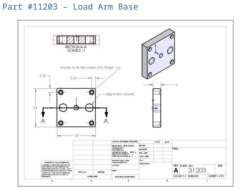
Part #11203 – Load Arm Base

Part #11204 – Load Arm Bracket

Part #11205 – Probe Adapter

Part #11301 – Membrane Clamp Lower

Part #11302 – Membrane Clamp Upper

Part #11303 – Membrane Clamp Spring End
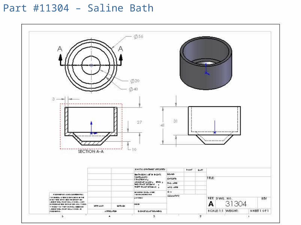
Part #11304 – Saline Bath
Top Related