


Languages
Pages
Legal


1
Multi-function digital amplifier with Bluetooth® INTRODUCTION The MICRO-PRO2-BT digital stereo amplifier is designed with Bluetooth capability as an additional audio source which can be used to broadcast audio signals and microphone signals wirelessly. This feature is especially useful in schools where wireless interference between classrooms can be problematic. The MICRO-PRO2-BT can also accept one wired microphone and two wired stereo line level audio inputs. Switching between inputs is made easy using the included IR remote control. The MICRO-PRO2-BT is an excellent companion amplifier to TV’s and displays where extra amplification is needed. The unit can be easily concealed behind equipment or in cabinetry.
MICRO-PRO2-BT Amplifier with BT receiver module
IRS-3060A02 IR RECEIVER
2
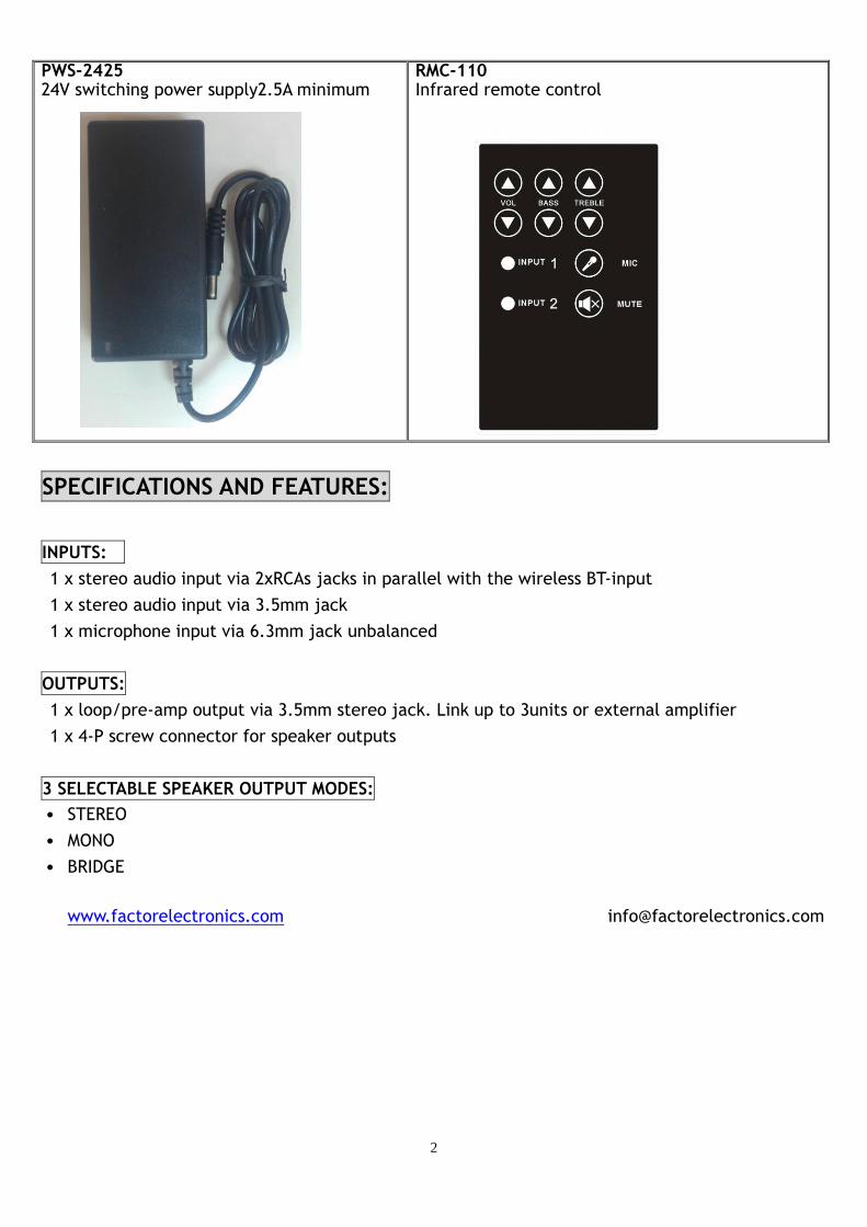
PWS-2425 24V switching power supply2.5A minimum
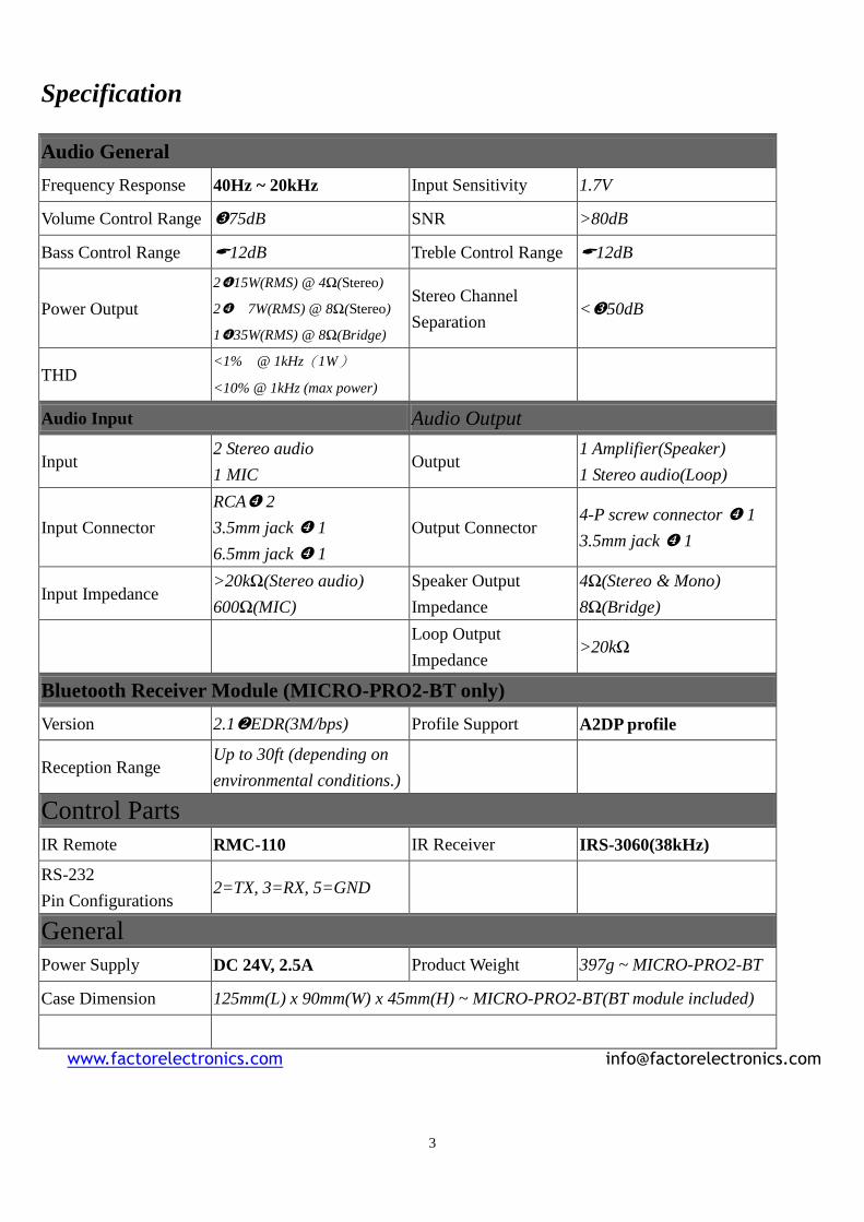
RMC-110 Infrared remote control
SPECIFICATIONS AND FEATURES:
INPUTS:
1 x stereo audio input via 2xRCAs jacks in parallel with the wireless BT-input
1 x stereo audio input via 3.5mm jack
1 x microphone input via 6.3mm jack unbalanced
OUTPUTS:
1 x loop/pre-amp output via 3.5mm stereo jack. Link up to 3units or external amplifier
1 x 4-P screw connector for speaker outputs
3 SELECTABLE SPEAKER OUTPUT MODES:
˙ STEREO
˙ MONO
˙ BRIDGE
www.factorelectronics.com [email protected]
3
Specification
Audio General
Frequency Response 40Hz ~ 20kHz Input Sensitivity 1.7V
Volume Control Range 75dB SNR >80dB
Bass Control Range 12dB Treble Control Range 12dB
Power Output
215W(RMS) @ 4Ω(Stereo)
27W(RMS) @ 8Ω(Stereo)
135W(RMS) @ 8Ω(Bridge)
Stereo Channel
Separation <50dB
THD <1% @ 1kHz(1W)
<10% @ 1kHz (max power)
Audio Input Audio Output
Input 2 Stereo audio
1 MIC Output
1 Amplifier(Speaker)
1 Stereo audio(Loop)
Input Connector
RCA 2
3.5mm jack 1
6.5mm jack 1
Output Connector 4-P screw connector 1
3.5mm jack 1
Input Impedance >20kΩ(Stereo audio)
600Ω(MIC)
Speaker Output
Impedance
4Ω(Stereo & Mono)
8Ω(Bridge)
Loop Output
Impedance >20kΩ
Bluetooth Receiver Module (MICRO-PRO2-BT only)
Version 2.1EDR(3M/bps) Profile Support A2DP profile
Reception Range Up to 30ft (depending on
environmental conditions.)
Control Parts
IR Remote RMC-110 IR Receiver IRS-3060(38kHz)
RS-232
Pin Configurations 2=TX, 3=RX, 5=GND
General
Power Supply DC 24V, 2.5A Product Weight 397g ~ MICRO-PRO2-BT
Case Dimension 125mm(L) x 90mm(W) x 45mm(H) ~ MICRO-PRO2-BT(BT module included)
www.factorelectronics.com [email protected]

4
CONTROL INTERFACES:
Three different inputs are available plus control of treble, bass & volume. Control the unit from the
front panel buttons, IR remote or RS-232.
Source selection using the IR remote control
˙Input 1: Stereo RCA (default source) and Bluetooth. (Note the RCA and Bluetooth inputs are
paralleled together. It’s best to turn your RCA source off when using Bluetooth
˙Input 2: Stereo 3.5mm
˙MIC 6.3mm unbalanced
Audio levels and tone settings using the remote control
˙The overall volume range (0 lowest ~ 20 highest),the factory preset power up value is 5
˙Bass (L.1 lowest ~ L.9 highest), the factory preset value is 5
˙Treble (H.1 lowest ~ H.9 highest), the factory preset value is 5
˙Mute : No signal output.
Note: The unit has a handy memory function for the following functions: Source Selection, Volume,
Bass, Treble and Mute. When the unit is powered OFF then ON all your previous settings will be
restored. All functions can be reset back to the factory default settings again. Press and hold the
“Mute” button for 3 seconds until the red LED illuminates steadily after flashing 3 times. Use the
amplifier front panel MUTE button or the IR remote control MUTE button to activate the reset
feature.
BT RECEIVER MODULE •Play back audio signals from any BT-enabled device Version 2.1 Use PC’s,
note book’s or MP3 players or Smart phones that support the A2DP profile
•The blue LED indicator shows the modes of operation for the BT receiver as follows: blinking for
pairing mode, a steadily light ON means a successful connection has been completed between the
BT-enabled device and the receiver
•A Unique 4-digit alpha-numeric ID for identifying each individual receiver is provided when multiple
units are used in one location.
• Reception Range: of up to 30 feet can be achieved depending on the building structure and
environmental conditions.
More on setting up your Bluetooth devices later in this manual under BLUETOOTH OPPERATIONS
• For indoor use only. Keep away from extreme temperatures, humidity, and moisture.
System power requirement: 24V, 2.5A
Dimensions: 125mm (L) x 90mm (W) x 45mm (H) BT module included –MICRO-PRO2-BT
www.factorelectronics.com [email protected]

5
FUNCTIONS MICRO-PRO2-BT:
www.factorelectronics.com [email protected]
Stereo Phone Inputs
3.5mm Jack Input
MIC 6.3mm Jack Input
Speaker Output Connectors
Loop/pre-amp output Power input jack
3.5mm IR Jack Input
Audio Control over RS-232
Bluetooth audio receiver
Source selection
Bass/Treble
VOLUME UP &DOWN
Mute
3 Selectable speaker outputs: Stereo /mono /bridge

6
INSTALLATIONS AND WIRING DIAGRAMS:
INSTALLATIONS:
Step 1: Audio connections
Connect line level audio devices such as MP3, CD, DVD, notebooks…etc., to the unit using the
Dual-RCA L/R jacks or stereo 3.5mm jack, 6.3mm MIC input is also provided. Or wireless audio
sources from BT-enabled devices can also be connected using Bluetooth.
Notes:
The wireless audio input for the MICRO-PRO2-BT is in parallel with dual-RCA inputs; if both inputs are
used at the same time the two sources will be mixed together.
Step 2: Speaker connections
Connect 14~18 AWG cable.to the speaker outputs (R+, R-, L+, L-)
Step 3: power connection
Connect the included power supply. The system will power up in Mute status/ with RED LED indicator
at the top of “Mute” button illuminated. The input 1 LED stereo RCA will also be illuminated. This is
the default factory preset power ON status.
Note: Power requirements 24V at the current rating of 2.5A is the minimum recommended Using a
power supply with a lower rating will result in the power supply shutting down or overheating due to
power overloaded.
Step 4: IR receiver connection
Plug in the 3.5mm IR receiver to the IR input jack. Please the IR receiver in a line of sight location to
the remote control. Use the remote control to select sources, volume control up & down, treble &
bass.
OPERATIONS:
˙Press the “Mute” button(the red LED will go off) The amplifier is un-muted and ready to use.
˙When playing your audio sources we suggest starting with the volume set at half way 50% .Then
adjust to achieve the desired volume level.
˙How to pair your Bluetooth® device
a. Switch the source to input 1
b. Place your Bluetooth® device within 1m of the unit.
c. Perform the pairing procedure from your Bluetooth® device to detect the MICRO-PRO2-BT. The
ID name “Audio adapter XXXX” will appear on the list of devices. If not, switch to a different
source and go back to the BT-source input which resets the BT functions and then repeat
the pairing operation.
d. Select “Audio adapter XXXX” on the display of the Bluetooth® device.
e. Input the passkey/pin code “0000” which is always required for first time connections from a
new device.
f. Start the Bluetooth® connection from the Bluetooth® device. Note: The Bluetooth is Capable of storing up to 8 pairings and also the unit is able to automatically reconnect to the previously paired device automatically.
[email protected] www.factorelectronics.com

7
Notes on Bluetooth operations
1) Working mode/sleep mode:
The Bluetooth unit provides 3minutes time for pairing or making connections when the Bluetooth
receiver is powered on and enters its working mode.
If there is no pairing/connection made within 3 minutes, the Bluetooth receiver will enter sleep mode
which means the “pair” function is no longer available until the Bluetooth receiver has been reset
usually via power off and power on again to re-start the 3 minutes of initial pairing time.
However the Bluetooth receiver can be woken up manually by any one of “8 previously paired”
devices even if the Bluetooth receiver is in the sleep mode. Simply open your Bluetooth device’s
pairing functions and connect to AUDIO ADAPTOR XXXX
2) Automatic connection:
The Bluetooth receiver will enter search mode after being powered on. The Bluetooth receiver will
sense and connect automatically to the previously last-paired device.
3) Memory function:
The Bluetooth receiver is capable of storing up to 8 pairings and any new pairing over 8 will
override the last or most recent pairing.
4) The Bluetooth connection between the receiver & transmitter may disconnect when the
transmitter is out of the reception range of the receiver (approximately 30feet). The Bluetooth
receiver is able to automatically connect to the transmitting device if the reception range is returned
to 30feet again within 30seconds of the connection being lost. If the Bluetooth connection is lost for
over 30 seconds the receiver and transmitter will need to re-pair
8
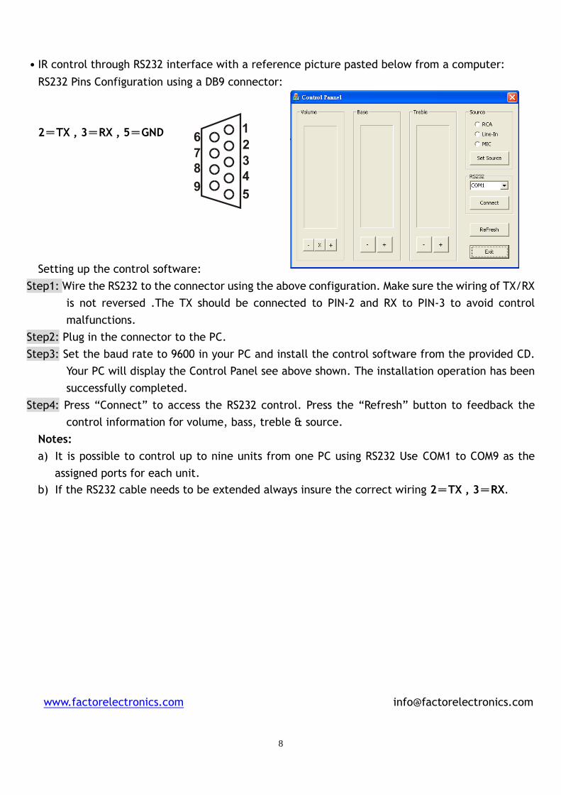
˙IR control through RS232 interface with a reference picture pasted below from a computer:
RS232 Pins Configuration using a DB9 connector:
2=TX , 3=RX , 5=GND
Setting up the control software:
Step1: Wire the RS232 to the connector using the above configuration. Make sure the wiring of TX/RX
is not reversed .The TX should be connected to PIN-2 and RX to PIN-3 to avoid control
malfunctions.
Step2: Plug in the connector to the PC.
Step3: Set the baud rate to 9600 in your PC and install the control software from the provided CD.
Your PC will display the Control Panel see above shown. The installation operation has been
successfully completed.
Step4: Press “Connect” to access the RS232 control. Press the “Refresh” button to feedback the
control information for volume, bass, treble & source.
Notes:
a) It is possible to control up to nine units from one PC using RS232 Use COM1 to COM9 as the
assigned ports for each unit.
b) If the RS232 cable needs to be extended always insure the correct wiring 2=TX , 3=RX.
www.factorelectronics.com [email protected]
9
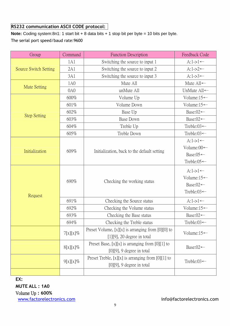
RS232 communication ASCII CODE protocol:
Note: Coding system:8n1: 1 start bit + 8 data bits + 1 stop bit per byte = 10 bits per byte.
The serial port speed/baud rate:9600
Group Command Function Description Feedback Code
Source Switch Setting
1A1 Switching the source to input 1 A:1->1←
2A1 Switching the source to input 2 A:1->2←
3A1 Switching the source to input 3 A:1->3←
Mute Setting 1A0 Mute All Mute All←
0A0 unMute All UnMute All←
Step Setting
600% Volume Up Volume:15←
601% Volume Down Volume:15←
602% Base Up Base:02←
603% Base Down Base:02←
604% Treble Up Treble:03←
605% Treble Down Treble:03←
Initialization 609% Initialization, back to the default setting
A:1->1←
Volume:00←
Base:05←
Treble:05←
Request
690% Checking the working status
A:1->1←
Volume:15←
Base:02←
Treble:03←
691% Checking the Source status A:1->1←
692% Checking the Volume status Volume:15←
693% Checking the Base status Base:02←
694% Checking the Treble status Treble:03←
7[x][x]% Preset Volume, [x][x] is arranging from [0][0] to
[1][9], 20 degree in total Volume:15←
8[x][x]% Preset Base, [x][x] is arranging from [0][1] to
[0][9], 9 degree in total Base:02←
9[x][x]% Preset Treble, [x][x] is arranging from [0][1] to
[0][9], 9 degree in total Treble:03←
EX:
MUTE ALL : 1A0
Volume Up : 600%
www.factorelectronics.com [email protected]
11
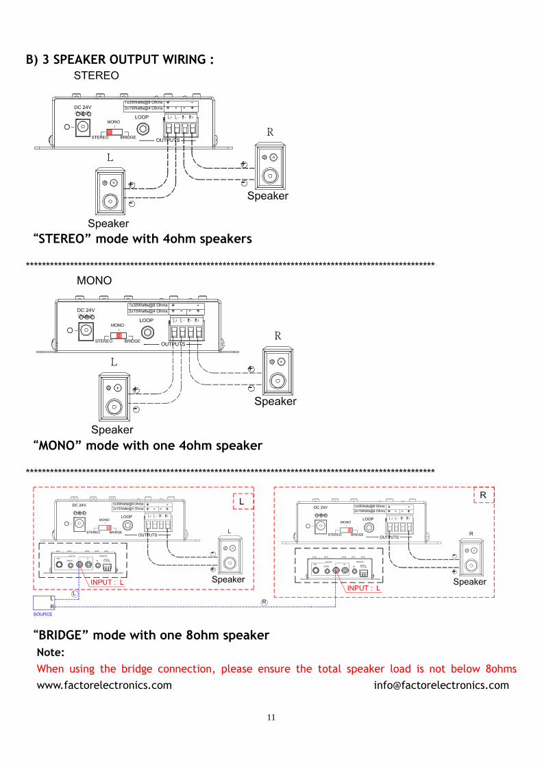
B) 3 SPEAKER OUTPUT WIRING :
“STEREO” mode with 4ohm speakers ******************************************************************************************************
“MONO” mode with one 4ohm speaker ******************************************************************************************************
“BRIDGE” mode with one 8ohm speaker
Note:
When using the bridge connection, please ensure the total speaker load is not below 8ohms
www.factorelectronics.com [email protected]

12
3) LOOP UPTO 3UNITS USING THE LOOP/PRE-AMP OUTPUT :
Note:
The loop output can also be used as a fixed line level output to feed additional higher power
amplifiers, pre-amps, mixers or receivers
www.factorelectronics.com [email protected]
Top Related