


Languages
Pages
Legal


University of Kentucky University of Kentucky
UKnowledge UKnowledge
Theses and Dissertations--Chemical and Materials Engineering Chemical and Materials Engineering
2018
MIXED MATRIX FLAT SHEET AND HOLLOW FIBER MEMBRANES MIXED MATRIX FLAT SHEET AND HOLLOW FIBER MEMBRANES
FOR GAS SEPARATION APPLICATIONS FOR GAS SEPARATION APPLICATIONS
Nicholas W. Linck University of Kentucky, [email protected] Digital Object Identifier: https://doi.org/10.13023/etd.2018.425
Right click to open a feedback form in a new tab to let us know how this document benefits you. Right click to open a feedback form in a new tab to let us know how this document benefits you.
Recommended Citation Recommended Citation Linck, Nicholas W., "MIXED MATRIX FLAT SHEET AND HOLLOW FIBER MEMBRANES FOR GAS SEPARATION APPLICATIONS" (2018). Theses and Dissertations--Chemical and Materials Engineering. 89. https://uknowledge.uky.edu/cme_etds/89
This Doctoral Dissertation is brought to you for free and open access by the Chemical and Materials Engineering at UKnowledge. It has been accepted for inclusion in Theses and Dissertations--Chemical and Materials Engineering by an authorized administrator of UKnowledge. For more information, please contact [email protected].

STUDENT AGREEMENT: STUDENT AGREEMENT:
I represent that my thesis or dissertation and abstract are my original work. Proper attribution
has been given to all outside sources. I understand that I am solely responsible for obtaining
any needed copyright permissions. I have obtained needed written permission statement(s)
from the owner(s) of each third-party copyrighted matter to be included in my work, allowing
electronic distribution (if such use is not permitted by the fair use doctrine) which will be
submitted to UKnowledge as Additional File.
I hereby grant to The University of Kentucky and its agents the irrevocable, non-exclusive, and
royalty-free license to archive and make accessible my work in whole or in part in all forms of
media, now or hereafter known. I agree that the document mentioned above may be made
available immediately for worldwide access unless an embargo applies.
I retain all other ownership rights to the copyright of my work. I also retain the right to use in
future works (such as articles or books) all or part of my work. I understand that I am free to
register the copyright to my work.
REVIEW, APPROVAL AND ACCEPTANCE REVIEW, APPROVAL AND ACCEPTANCE
The document mentioned above has been reviewed and accepted by the student’s advisor, on
behalf of the advisory committee, and by the Director of Graduate Studies (DGS), on behalf of
the program; we verify that this is the final, approved version of the student’s thesis including all
changes required by the advisory committee. The undersigned agree to abide by the statements
above.
Nicholas W. Linck, Student
Dr. Douglass S. Kalika, Major Professor
Dr. Matthew Beck, Director of Graduate Studies

MIXED MATRIX FLAT SHEET AND HOLLOW FIBER MEMBRANES FOR GAS SEPARATION APPLICATIONS
Dissertation
A dissertation submitted in partial fulfillment of the requirements for the degree of Doctor of Philosophy in the College of Engineering at the
University of Kentucky
By
Nicholas W. Linck
Lexington, KY
Directors: Dr. Douglass S. Kalika, Professor of Chemical Engineering Dr.
Matthew Weisenberger, Associate Director, Materials Technologies,
Center for Applied Energy Research
Lexington, KY
2018
Copyright © Nicholas William Linck 2018

ABSTRACT OF DISSERTATION
MIXED MATRIX FLAT SHEET AND HOLLOW FIBER MEMBRANES FOR GAS SEPARATION APPLICATIONS
Mixed matrix membranes (MMM) offer one potential path toward exceeding the Robeson upper bound of selectivity versus permeability for gas separation performance while maintaining the benefits of solution processing. Many inorganic materials, such as zeolites, metal-organic frameworks, or carbon nanotubes, can function as molecular sieves, but as stand-alone membranes are brittle and difficult to manufacture. Incorporating them into a more robust polymeric membrane matrix has the potential to mitigate this issue.
In this work, phase inversion polymer solution processing for the fabrication and testing of asymmetric flat sheet mixed matrix membranes was employed with CVD-derived multiwall carbon nanotubes (MWCNTs) dispersed in a polyethersulfone (PES) matrix. The effect of MWCNT loading on membrane separation performance was examined. Notably, a distinct enhancement in selectivity was measured for several gas pairs (including O2/N2) at relatively low MWCNT loading, with a peak in selectivity observed at 0.1 wt% loading relative to PES. In addition, no post-treatment (e.g. PDMS caulking) was required to achieve selectivity in these membranes. In contrast, neat PES membranes and those containing greater than 0.5 wt.% MWCNT showed gas selectivity characteristic of Knudsen diffusion through pinhole defects. These results suggested
that at low loading, the presence of MWCNTs suppressed the formation of surface defects in the selective layer in flat sheet mixed matrix membranes.
Additionally, a bench-scale, single-filament hollow fiber membrane spinning line was designed and purpose-built at the University of Kentucky Center for Applied Energy Research (CAER). Hollow fiber membrane spinning capability was developed using polyethersulfone (PES) solution dopes, and the process was expanded to include polysulfone (PSf) as well as mixed matrix membranes. The effects of key processing parameters, including the ratio of bore to dope velocities, the spinning air gap length, and the draw-down ratio, were systematically investigated. Finally, direct hollow fiber analogues to flat sheet mixed matrix membranes were characterized. Consistent with the flat sheet experiments, the mixed matrix hollow fiber membranes showed a local maximum in selectivity at a nominal loading of 0.1 wt.% MWCNT relative to the polymer, suggesting that the pinhole suppression effect introduced by MWCNTs was not limited to flat sheet membrane casting.
The development of asymmetric hollow fiber mixed matrix membrane processing and testing capability at the UK Center for Applied Energy Research provides a platform for the further development of gas separation membranes. Using the tools developed through this work, it is possible to further push the frontiers of mixed matrix gas separation by expanding the capability to include more polymers, inorganic fillers, and post treatment processes which previously have been focused primarily on the flat sheet membrane geometry.
KEYWORDS: Hollow fiber membranes, mixed matrix membranes, gas separation, carbon nanotubes, polyethersulfone
Nicholas W. Linck
22 October 2018

MIXED MATRIX FLAT SHEET AND HOLLOW FIBER MEMBRANES FOR GAS SEPARATION APPLICATIONS
By
Nicholas W. Linck
Dr. Douglass S. Kalika
Dr. Matthew Weisenberger
Dr. Matthew Beck
22 October 2018
Director of Graduate Studies
Co-Director of Dissertation
Co-Director of Dissertation

Acknowledgements
I would like to acknowledge my advisors, Dr. Matthew Weisenberger and Dr.
Douglass Kalika for the kindness, support, and guidance throughout this entire process.
It was thoroughly enjoyable to have them both guiding my research, with Dr.
Weisenberger providing most of the day to day advice, assistance, and instruction, while
Dr. Kalika provided the project with more big picture guidance and direction. Both of
them provided me with the excellent advice and encouragement that I needed to
complete this process. I also would like to thank my committee members, Dr. Isabel
Escobar, Dr. Mark Meier, and Dr. John Balk, for providing insight and interesting
questions to consider during the process.
I would also like to thank my past and present labmates, Dr. David Eaton, Ashley
Morris, Jordan Burgess, Sarah Edrington, Nik Hochstrasser, Ruben Sarabia Riquelme, and
Aaron Owen for all of their assistance and contributions to my research work.
Additionally, I would like to thank Roger Perrone and Steve Summers for their assistance
with the construction of the hollow fiber membrane spinning line.
Finally, I would like to acknowledge my wife Rachel as well as my parents, John
and Jill Linck. Without their love and support I do not believe that I would have ever
finished this work.
This material is based upon work supported by the National Science Foundation
under Cooperative Agreement No. 1355438.
iii

Table of Contents
List of Tables…………………………………………………………………………………..………………………………x
List of Figures…………………………………………………………………………………………….…………………..xi
Chapter 1: Introduction ……………………….………………………………………………………………………..1
1.1 Polymeric Membrane Separations …..…….………………………..……………………………………..1 1.1.1 Homogeneous Dense Film Membranes …...…………………………….………………………… 4 1.1.2 Asymmetric Membranes ….………..……………………………………………………..………………5 1.1.2.1 Flat Sheet Membranes …………………………………………………………….………………………10 1.1.2.2 Hollow Fiber Membranes ………………………………………………………………………………12 1.1.2.3 Pinhole Defects and Caulking ……………………………………………………………………..15 1.2 Gas Separation ………………………………………………………………………………………………………17 1.2.1 Equations and Terminology for Gas Separations .…………………………………………….19 1.2.1.1 Permeability Coefficient and Permeance …………………………………………………………19 1.2.1.2 Selectivity …………….…………………………………………………………………….……………………20 1.2.2 The Robeson Upper Bound ...…………………………………………………….…………………….21 1.2.3 Air Separation ………………………………………………………………………….………………………23 1.2.3.1 Nitrogen Enriched Air (NEA) …………………………………………………….……………………...24 1.2.3.2 Oxygen Enriched Air (OEA) ……………………………………………………………………………...25 1.2.4 Natural Gas Purification …………………………………………………………………………………..27 1.3 Relevant Membrane Polymers of Interest ……………………………..………………………………29 1.3.1 Cellulose Acetate (CA) ………………………………………………………………….………………….29 1.3.2 Poly(aryl ether sulfones) ..……………………………………………………………………….….……30 1.3.3 Polyimides …………………………………………………………………………………………………….…33 1.3.4 Polymers of Intrinsic Microporosity (PIMs) ………………………………………………………34 1.3.5 Mixed Matrix Membranes (MMM) …………………………………………………………………..36 1.3.5.1 Zeolite MMM ………………………………………………………………………………………………..…37 1.3.5.2 Metal Organic Framework (MOF) MMM ………………………………………………………….38 1.3.5.3 Carbon Nanotube (CNT) MMM ………………………………………………………………………..40 1.4 Research Objectives ……………………………………………………………………………………………...42 1.5 References …………………………………………………………………………………………………….……...46
Chapter 2: Materials and Methods …………………………………….……………………..…………………53
2.1 Introduction…….…………………………………………………………………………………………………..…53 2.2 Materials………………………………………………………………………………………………………………..53 2.2.1 Polymers……….………………………………………………………………………………………...………….53
iv
2.2.1.1 Polyethersulfone (PES) ………..…………………………………………………………………………..53 2.2.1.2 Polysulfone (PSf) ……………………..………………………………………………………………………54 2.2.1.3 Polydimethylsiloxane (PDMS) ………………………….…………………………………………….55 2.2.2 Solvents ……………………………………………………………………….………………………………….55 2.2.2.1 N,N-dimethylacetimide (DMAc) …………………..…………………………………….………….55 2.2.2.2 N-methylpyrrolidone (NMP) …………………………….…………………………………………...56 2.2.3 Inorganic Fillers .……………………………………………………………………………………………….56 2.2.3.1 Carbon Nanotubes (CNTs) ………………………..………………………….………………………….57 2.2.3.2 Carbon Black …………………………………………………………………………………………………...59 2.3 Membrane Fabrication Methods …………………………………………………………………………..59 2.3.1 Flat Sheet Membranes ………….………………………………………………………………………...59 2.3.1.1 Dope Preparation ………………………….………………………………………………………………..59 2.3.1.1.1 Standard Polymer Dope ………………..…………………………………………………………..59 2.3.1.1.2 Mixed Matrix Membrane Dope ………………………………………………………………….60 2.3.1.2 Thin Film Casting/Solvent Exchange and Drying .……………………………………………62 2.3.2 Hollow Fiber …..………………………………………………………………………………………………..63 2.3.2.1 Dope Preparation ….………………………………………………………………………………………63 2.3.2.2 Hollow Fiber Membrane Spinning Procedure ……………….……………………………….64 2.4 Membrane Gas Permeation Testing Methods ………………….…………………………………68 2.4.1 Permeation Testing Apparatus ………………………….…………………………………………….68 2.4.2 Flat Sheet Membrane Testing Procedure .………………………………………………………..69 2.4.3 PDMS Caulking …………………..…………………………..…………………………………………….…71 2.4.4 Hollow Fiber Membrane Testing ……………………….…………………………..………………..74 2.4.4.1 Hollow Fiber Membrane Module Module Construction ..………………………………74 2.4.4.2 Hollow Fiber Membrane Module Testing …………………………………………………………76 2.5 Characterization Methods ……………………………..…………………………………………………...76 2.5.1 Parallel Plate Rheometry ……………………………………………………………………………….…76 2.5.2 Scanning Electron Microscopy (SEM) …………………………………………………………….…77 2.5.3 Porometer …………………………………………………………………………………………………….…77 2.6 References ……………………………………………………………………………………….……………….…..79
Chapter 3: Development of PES-MWCNT Flat Sheet Membranes ………………….……..…….80
3.1 Introduction ………………………………………………………………………….……………………………...80 3.1.1 Asymmetric Flat Sheet Membranes .……………………………………………….……………….80 3.1.2 Material Systems of Interest ……………..……………………………….……………………………83 3.1.2.1 Membrane Polymer …………………………………………………………………………………..…….83 3.1.2.2 Mixed Matrix Membranes ……………………………………………………………………………….84 3.2 Results and Discussion……………………..………………………..………………………………………….87
v

3.2.1 Rheology of Membrane Casting Dopes ……………………..…………………………………..…87 3.2.1.1 Polyethersulfone Viscosity Measurements ………………………………………………………87 3.2.1.2 Mixed Matrix Dope Viscosity Measurements ……………………………………………..…89 3.2.2 Flat Sheet Membrane Morphology ………………………………………….………………………90 3.2.2.1 Effect of Coagulation Bath Composition on Membrane Morphology…………...90 3.2.2.2 Effect of Polymer Concentration on Membrane Morphology ……….………………97 3.2.2.3 Effect of Solvent on Membrane Morphology …………………………………………………103 3.2.2.4 Effect of MWCNT Loading on PES Membrane Morphology ……….………………..109 3.2.3 Gas Permeance and Selectivity for Flat Sheet Membranes ….....……………………….114 3.2.3.1 Permeance and Selectivity of PES and PSf Membranes ………………….................114 3.2.3.2 Effect of MWCNT Loading on PES Membrane Permselectivity ……….................114 3.2.3.3 Effect of Carbon Black Loading on PES Membrane Permselectivity ………………..123 3.2.3.4 Effect of MWCNT Loading on PES-PDMS Membrane Permselectivity …………….127 3.2.3.5 Effect of Carbon Black Loading on PES-PDMS Membrane Permselectivity ……..131 3.3 Conclusions …………………………………………………………………………………………………………134 3.4 References ………………………………………………………………….…………………………………......137
Chapter 4: Hollow Fiber Membrane Spinning and PES-MWCNT Hollow Fiber Membranes…………………………………………………………………………………………………..…..141
4.1 Introduction……………………………………………………………………………………………………….142 4.2 Materials and Methods ……………………………………………………………………………………….143 4.3 Results and Discussion ………………………………………………………………………………………..143 4.3.1 Effects of Varying Processing Parameters on HFM Characteristics …………………143 4.3.1.1 Ratio of Bore Velocity to Dope Velocity (Vb/Vd) …………………………………………..146 4.3.1.2 Air Gap Distance ……………………………………………………………………………………………151 4.3.1.3 Ratio of Take-up Velocity to Dope Velocity (Draw Down Ratio) …………………..155 4.3.2 Gas Separation Properties of Hollow Fiber Membranes …………………………………159 4.3.3 Effect of Multiwall Carbon Nanotubes (MWCNT) Addition …………………………….165 4.3.3.1 Effect of Loading on PES-MWCNT Mixed Matrix HFM Permselectivity …………168 4.3.3.2 Effect of Loading on PES-Carbon Black Mixed Matrix HFM Permselectivity …176 4.4 Conclusions………………………………………………………………………………………………………….179 4.5 References …………………………………………………………………………………………………..........183
vi

5.1.1 Flat Sheet Membranes ………………………………….…………………………………….…………..185 5.1.2 Hollow Fiber Membranes ……………………………………………………………………………….188 5.2 Future Work ………………………………………………………………………………………………………..190 Bibliography .…….....…………………………………………………………………………….…………………….194 Vita …...……………………………………………………………………………………………...………………………201
vii
Chapter 5: Conclusions and Future Work ………………………..…………………………………………185
5.1 Conclusions ………………………………………………………………………………………………………….185

Table 3.1: Membrane casting parameters and test conditions for single gas permeance studies ……………..…………………………………………………………………………………….114
Table 3.2: Permeance and ideal selectivity of N2 and O2 for unfilled PES and PSf membranes in the as-cast and PDMS-caulked state ...…………………………..……………116
Table 3.3: Summary of the permeance of N2 and O2 as well as the O2/N2 ideal selectivity for selected mixed matrix flat sheet membranes………………………….……………………………123
Table 4.1: Summary of hollow fiber membrane spinning conditions used in flowrate, air gap, and draw down ratio studies.…………………………………………………………………………..…144
Table 4.2: Processing parameters for Vb/Vd, air gap, and draw down ratio experiments .………………………………………………………………….……………………………….147
Table 4.3: Processing parameters used for the production of hollow fiber membranes for gas separation testing…………………………………………………………………………………………..160
Table 4.4: Summary of the permeance of N2 and O2 as well as the selectivity of O2/N2 for the unfilled hollow fiber and flat sheet membranes ……………………………………………..161
Table 4.5: O2/N2 transport properties for MWCNT-loading hollow fiber membranes as compared to unfilled caulked membranes………………………………………………………….…171
Table 4.6: O2/N2 transport properties for MWCNT-loading flat sheet and hollow fiber membranes with and without PDMS caulking………….………………………………….……175
Table 4.7: Comparison of the permeance of N2 and O2 and O2/N2 selectivity for PES filled with carbon black versus the unfilled PES membrane………………………………………………...177
Table 4.8: Comparison of the permeance of N2 and O2 and O2/N2 selectivity of caulked PES hollow fibers filled with 0.1wt.% carbon black to that of the unfilled membrane….................................................................................................................178
viii
List of Tables

Figure 1.1: A schematic representation of the three primary diffusion mechanisms that occur within polymeric gas separation membranes …........………….....…………………………….2
Figure 1.2: Schematic representation of an asymmetric flat sheet membrane. (A) ~0.1-1 µm thick dense layer, where gas separation occurs via solution diffusion (B) ~100-200 µm thick porous layer, which provides mechanical support……………………………………………7
Figure 1.3: Generic ternary phase diagram between polymer, solvent, and non-solvent. (A) Binodal line, (B) Spinodal line, (C) Critical point, where binodal and spinodal are equal, (D) Meta-stable region, (E) Phase separation paths ………....…………..8
Figure 1.4: Schematic diagram of a spiral wound membrane module…………………………..11
Figure 1.5: Schematic diagram of hollow fiber membrane spinning line (A) Dope extrusion pump, (B) Bore injection pump, (C) Filtration manifold, (D) Extrusion die (spinneret), (E) Coagulation bath, (F) Take-up godet rollers, and (G) Wash winder. Dashed line represents pathway of the nascent hollow fiber membrane……………………………………………………………………………………….………………………….13
Figure 1.6: Schematic diagram of a porous asymmetric composite membrane (left), along with the electrical resistance analog (right)…………………………………………………………17
Figure 1.7: Schematic plot of the Robeson upper bound relationship between membrane efficiency (selectivity) and throughput (permeability) ……………..22
Figure 1.8: Polymer repeat unit for (A) polyethersulfone (PES), (B) polysulfone (PSf), and (C) polydimethylsiloxane (PDMS)………………………………………………………………………………….31
Figure 1.9: General reaction taking place during the thermal rearrangement process…34
Figure 1.10: Preparation of PIM-1 polymer of intrinsic microporosity……………..………….35
Figure 1.11: Schematic representation of an asymmetric flat sheet mixed matrix membrane. (A) Dense separating layer, (B) Porous support layer, (C) Dispersed inorganic filler material, which adds a component of molecular sieving to the solution diffusion mechanism…………………………………………………………………………………………………………………..37
Figure 2.1: Chemical structures for solvents used in membrane casting: (A) N,N-dimethylacetimide and (B) N-methylpyrrolidone………………………………………………………….56
ix
List of Figures
Figure 2.2a: (Top) Schematic diagram of hollow fiber membrane spinning line (A) Dope inlet, (B) Bore fluid inlet, (C) Extrusion die (spinneret), (D) Coagulation bath, (E) Take-up godet rollers, and (F) Wash winder. (Bottom) Photograph of hollow fiber spinning line……………………………………………………………………………………………………………………………….65
Figure 2.2b: Schematic diagram of the bore fluid and dope in the air gap between the spinneret and the coagulation bath (left), and a close-up photograph of the air gap with PES dope (right) ……………………………………………………………………………………………………65
Figure 2.3: (Top) schematic diagram of hollow fiber extrusion die. (Bottom) diagram of dope annulus and bore needle………………………………………………………………………………..66
Figure 2.4: Diagram of the hollow fiber membrane separation testing apparatus. (A) Gas source, which can flow nitrogen (N2), helium (He), carbon dioxide (CO2), or oxygen (O2), (B) Gas flow regulator, (C) Gas pressure gauge, (D) Membrane module, which can be either flat sheet membrane holder or hollow fiber membrane module, and (E) Soap film flowmeter……………………………………………………………………………68
Figure 2.5: Schematic diagram of Millipore Microsyringe Stainless Steel Filter Holder (Cat# xx3002514) that was used for flat sheet membrane testing. (A) Outlet of the filter holder, (B) Flat Teflon O-ring, (C) Stainless steel screen, (D) Flat sheet asymmetric membrane sample, (E) Rounded Teflon O-ring, (F) Top of filter holder with NPT inlet…..70
Figure 2.6: Schematic diagram of HFM PDMS caulking soak (left) and photograph of HFM PDMS caulking soak (right)…………………………………………………………………………………..72
Figure 2.7: Hollow fiber membrane module (A) Schematic diagram of HFM module, (B) Empty module shell, (C) HFM bundle, (D) Module prepared for epoxy injection, (E) End view of potted, open fibers, (F) Completed module……………………………………………………..75
Figure 3.1: Schematic diagram demonstrating the mechanism by which selectivity is improved in a mixed matrix membrane. (A) Smaller gas molecules flow freely due to the porous nature of the filler material; (B) larger gas molecules (rejected from the filler via size discrimination are forced to take a more tortuous path through the dense separating layer of the membrane, decreasing their permeability…………………………………………………85
Figure 3.2: Relationship between the polymer dope viscosity and polymer concentration for PES in NMP and DMAc, as well as PSf in NMP …………………………………88
x

Figure 3.3: Complex viscosity vs. angular frequency for PES-MWCNT and PES-Carbon black dopes with varying filler loadings at 25°C. PES-XXMWCNT corresponds to dope composed of 30 wt.% PES in NMP with XX wt.% MWCNT (or CB) relative to the polymer………………………………………………………………………………………………………………………..89
Figure 3.4a-b: SEM micrographs of PES thin films coagulated from 38.5 wt.% PES-DMAc dope in bath composed of (A) 0 wt.%, (B) 50 wt.% DMAc/water mixture. Arrows indicate surface that was exposed to coagulation bath. Inset: top surface of thin films at 800x magnification……..………………………………………………………………………………….92
Figure 3.4c-d: SEM micrographs of PES thin films coagulated from 38.5 wt.% PES-DMAc dope in bath composed of (C) 60 wt.%, (D) 70 wt.% DMAc/water mixture. Arrow indicates exposure face. Inset: top surface of thin films at 800x magnification .93
Figure 3.5a-b: SEM micrographs of PSf thin films coagulated from 35 wt.% PES-NMP dope in bath composed of (A) 0 wt.%, (B) 50 wt.% NMP/water mixture. Arrow indicates exposure face…………………………………….………………………………………………………….95
Figure 3.5c-d: SEM micrographs of PSf thin films coagulated from 35 wt.% PSf-NMP dope in bath composed of (A) 60 wt.%, (B) 70 wt.% NMP/water mixture. Arrow indicates exposure face ……………………….....………………………………………………………………….96
Figure 3.6a-b: SEM micrographs of PES thin films cast using dope composed of (A) 15 wt.% and (B) 20 wt.% PES in DMAc with deionized water as the coagulation medium. Arrow indicates exposure face ………………………………………………………………………98
Figure 3.6c-d: SEM micrographs of PES thin films cast using dope composed of (C) 25 wt.% and (D) 30 wt.% PES in DMAc with deionized water as the coagulation medium. Arrow indicates exposure face ………………………………………………………………………99
Figure 3.6e: SEM micrographs of PES thin films cast using dope composed of (E) 35 wt.% PES in DMAc with deionized water as the coagulation medium. Arrow indicates exposure face …………………………………………….………………………………………………………………100
Figure 3.7a-b: SEM micrographs of PSf thin films cast using dope composed of (A) 25 wt.% and (B) 27.5 wt.% PSf in NMP with deionized water as the coagulation medium. Arrow indicates exposure face.……………………………………………………………………101
Figure 3.7c-d: SEM micrographs of PSf thin films cast using dope composed of (C) 30 wt.% and (D) 32.5 wt.% PSf in NMP with deionized water as the coagulation medium. Arrow indicates exposure face ……………………………………………………………………102
xi

Figure 3.7e: SEM micrographs of PSf thin films cast using dope composed of 35 wt.% PSf in NMP with deionized water as the coagulation medium. Arrow indicates exposure face ………………………..………………………………………………………………………………….103
Figure 3.8a-b: SEM micrographs of PES thin films coagulated from 30 wt.% PES-NMP dope in bath composed of (A) 0 wt.%, (B) 50 wt.% NMP/water mixture. Arrow indicates exposure face ………………………………………..…………………………………………………..104
Figure 3.8c-d: SEM micrographs of PES thin films coagulated from 30 wt.% PES-NMP dope in bath composed of (C) 60 wt.%, (D) 70 wt.% NMP/water mixture. Arrow indicates exposure face ……………………………………………………………………………………………..105
Figure 3.9a-b: Comparison of SEM micrographs of 30 wt.% PES thin films cast from (A) DMAc and (B) NMP using deionized water as the coagulation medium. Arrow indicates surface that was exposed to coagulation bath……………………………………………107
Figure 3.9c-d: Comparison of SEM micrographs of 30 wt.% PES thin films cast from (C) DMAc and (D) NMP using 70 wt.% solvent in water as the coagulation medium. Arrow indicates surface that was exposed to coagulation bath …………………...…………..108
Figure 3.10: Optical microscope images of 30 wt.% PES in NMP dopes with (A) 0.05, (B) 0.1, and (C) 0.5 wt.% MWCNT dispersions (Arrow indicates MWCNT agglomerate that was not removed during centrifugation). Nominal magnification is 50x ….………..110
Figure 3.11: Comparison of SEM micrographs of (A) unfilled PES flat sheet membrane and (B) PES flat sheet membrane loaded with 0.1 wt.% MWCNT. Dopes contain 30 wt.% PES in NMP and deionized water was used as the coagulation medium. Arrow indicates exposure face……………………………………………………………….…………………………….111
Figure 3.12: Comparison of SEM micrographs of (A) unfilled 30 wt.% PES-NMP flat sheet membrane and (B) 30 wt.% PES-NMP flat sheet membrane loaded with 0.1 wt.% MWCNT. 70 wt.% NMP/water was used as the coagulation medium. Arrow indicates exposure face. Inset: Membrane surface that was exposed to coagulation bath………112
Figure 3.13: (Left) SEM image of PES-0.1MWCNT dense film cross-section. Arrows indicate MWCNTs. (Right) photograph of PES and PES-0.1MWCNT membrane coupons, showing macroscopic color change that accompanies MWCNT dispersion…113
Figure 3.14a: Average He, CO2, O2, and N2 permeance (GPU) of PES-MWCNT mixed
matrix membranes, plotted against MWCNT loading. Each data point was measured in triplicate and error bars represent standard deviation of the three measurements……118
xii

Figure 3.14b: Average He/N2, CO2/N2, and O2/N2 ideal selectivity of PES-MWCNT
mixed matrix membranes, plotted against MWCNT loading. Each data point was measured in triplicate and error bars represent standard deviation of the three measurements ................................................................................................................119 Figure 3.15a: Average He, CO2, O2, and N2 permeance (GPU) of PES-carbon black mixed
matrix membranes, plotted against carbon black loading. Each data point was measured in triplicate and error bars represent standard deviation of the three measurements..125
Figure 3.15b: Average He/N2, CO2/N2, and O2/N2 ideal selectivity of PES-carbon black
mixed matrix membranes, plotted against carbon black loading. Each data point was measured in triplicate and error bars represent standard deviation of three points……126
Figure 3.16a: Average He, CO2, O2, and N2 permeance (GPU) of PDMS-caulked PES-
MWCNT mixed matrix membranes, plotted against MWCNT loading. Each data point was measured in triplicate and error bars represent standard deviation of the three measurements……………………………………………………………………………………………………………129
Figure 3.16b: Average He/N2, CO2/N2, and O2/N2 ideal selectivity of PDMS-caulked PES-
MWCNT mixed matrix membranes, plotted against MWCNT loading. Each data point was measured in triplicate and error bars represent standard deviation of the three measurements……………………………………………………………………………………………………………130
Figure 3.17a: Average He, CO2, O2, and N2 permeance (GPU) of PDMS-caulked PES-
carbon black mixed matrix membranes, plotted against carbon black loading. Each data point was measured in triplicate and error bars represent standard deviation of three points…………………………………………………………………………………………………………………………132
Figure 3.17b: Average He/N2, CO2/N2, and O2/N2 ideal selectivity of PDMS-caulked PES-
carbon black mixed matrix membranes, plotted against carbon black loading. Each data point was measured in triplicate and error bars represent standard deviation of three points…………………………………………………………………………………………………………………………133
Figure 4.1a: SEM micrograph showing typical hollow fiber membrane wall morphology, with the dense separating layer, porous support layer, and macrovoids indicated ..145 Figure 4.1b: SEM micrograph showing typical hollow fiber membrane cross section, with outer diameter (OD), inner diameter (ID), and wall thickness (WT) indicated …...146
Figure 4.2: SEM micrographs of PES hollow fiber membranes spun from 30 wt% PES/DMAc dope with Vb/Vd = (A) 0.5, (B) 2.5, and (C) 4.0 ………………...…………………..149
xiii

Figure 4.3: Relationship between fiber dimensions and Vb/Vd for hollow fibers spun from 30 wt% PES/DMAc dope using a 70 wt% DMAc/water bore fluid and a pure water coagulation bath (n = 10 for each fiber sample)………………………………….....……….151
Figure 4.4: Relationship between fiber dimensions and air gap distance for hollow fibers spun from 30 wt% PES/DMAc dope using a 70 wt% DMAc/water bore fluid and a pure water coagulation bath (n = 10 for each fiber sample) …………………....…………….152
Figure 4.5: SEM micrographs of the porous support layer of hollow fiber membranes spun from 30 wt% PES/DMAc dope with (A) 3 cm air gap distance and (B) 7 cm air gap distance………………………………………………………………………………………………………………………154
Figure 4.6: SEM micrographs of PES hollow fiber membranes spun from 30 wt% PES/DMAc dope with DDR = (A) 1.0, (B) 1.5, (C) 2.0, and (D) 2.5 ……………………………156
Figure 4.7: Relationship between fiber dimensions and the square root of draw down ratio for hollow fiber membranes spun from 30 wt% PES/DMAc dope, with 70 wt% DMAc/water bore fluid and deionized water coagulation bath (n = 10 for each fiber sample)………………………………………………………………………………………………………………………157
Figure 4.8: SEM micrographs of substructure of PES hollow fiber membranes spun from 30 wt% PES/DMAc dope with DDR = (A) 1.0, (B) 1.5, (C) 2.0, and (D) 2.5 ............158
Figure 4.9a: SEM micrographs of hollow fiber membranes spun from dope composed of 30 wt.% PES in NMP (left) and dope composed of 30 wt.% PES in NMP with a MWCNT loading of 0.1 wt.% (right)…………………………………………………………………………….…………….166
Figure 4.9b: Macroscopic comparison between neat PES HFM (top) and PES HFM loaded with 0.1 wt.% MWCNT (bottom)…………………………………………………………….………166
Figure 4.10a: Plot of He, CO2, O2, and N2 permeance against MWCNT loading for PES-MWCNT mixed matrix hollow fiber membranes. Connecting lines provided as a guide for the eye (n = 3 for each composition)…………………………………………………………………………..169
Figure 4.10b: Plot of ideal selectivity for He/N2, CO2/N2, and O2/N2 against MWCNT loading of PES-MWCNT mixed matrix hollow fiber membranes. Connecting lines provided as a guide for the eye (n = 3 for each composition)………………………………………170
Figure 4.11a: Plot of He, CO2, O2, and N2 permeance against MWCNT loading for PDMS caulked PES-MWCNT mixed matrix hollow fiber membranes. Connecting lines provided as a guide for the eye (n = 3 for each composition)…………………………………………………….173
xiv
Figure 4.11b: Plot of He/N2, CO2/N2, and O2/N2 ideal selectivity against MWCNT loading for PDMS caulked PES-MWCNT mixed matrix hollow fiber membranes. Connecting lines provided as a guide for the eye (n = 3 for each composition) ..………174
xv

Chapter 1: Introduction and Background
1.1 Polymeric Membrane Separations
The first experimental instance of a nonporous polymeric material demonstrating
gas permeability was in 1831, when John K. Mitchell filled several balloons, composed of
cis-poly(isoprene), with hydrogen gas and left them on the ceiling of his lecture room
[1]. When he observed the balloons slowly drop to the floor of the room, Mitchell
hypothesized that the hydrogen must be somehow passing through the walls of the
balloons. He then repeated the experiment with several other gases, noting that the
gases permeated through the walls of the balloon at differing rates, but also that the
rates of permeation were not necessarily correlated solely with the size of the
permeating molecule. These two fundamental observations are the foundation upon
which the commercial development of polymeric gas separation membranes would
eventually be built over a century later.
In an ideal scenario, a gas separation membrane would be made of a material that
takes a feed mixture of gases A and B and produces a permeate stream of pure gas A
and a retentate stream of pure gas B. However, the classes of materials that have the
ability to provide a perfect separations, such as palladium based membranes for
hydrogen purification [2], are typically very delicate and/or cannot be economically
produced at the scale that is necessary for practical processing volumes. The main
challenge in the development of gas separation membranes, which polymeric
membranes can address, is the industrial-scale production of membrane modules that
1
offer the highest possible permeability and selectivity, and that are sufficiently robust to
withstand high operating pressures and potentially aggressive process environments.
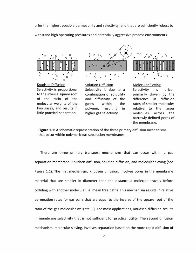
There are three primary transport mechanisms that can occur within a gas
separation membrane: Knudsen diffusion, solution diffusion, and molecular sieving (see
Figure 1.1). The first mechanism, Knudsen diffusion, involves pores in the membrane
material that are smaller in diameter than the distance a molecule travels before
colliding with another molecule (i.e. mean free path). This mechanism results in relative
permeation rates for gas pairs that are equal to the inverse of the square root of the
ratio of the gas molecular weights [3]. For most applications, Knudsen diffusion results
in membrane selectivity that is not sufficient for practical utility. The second diffusion
mechanism, molecular sieving, involves separation based on the more rapid diffusion of
Knudsen Diffusion Selectivity is proportional to the inverse square root of the ratio of the molecular weights of the two gases, and results in little practical separation.
Solution Diffusion Selectivity is due to a combination of solubility and diffusivity of the gases within the polymer, resulting in higher gas selectivity.
Molecular Sieving Selectivity is driven primarily driven by the difference in diffusion rates of smaller molecules relative to the larger molecules across the narrowly defined pores of the membrane.
Figure 1.1: A schematic representation of the three primary diffusion mechanisms that occur within polymeric gas separation membranes.
2

the smaller molecules in a feed mixture, with simultaneous rejection, (i.e. filtering) of
larger molecules. Membranes based on molecular sieving have received a fair amount of
research attention in the last few decades due to their high selectivity and permeability
compared to solution diffusion membranes. Zeolites and metal-organic frameworks
(MOFs) are examples of the classes of membrane materials that offer high selectivity
based on this principle, as their structure encompasses a narrow distribution of pore
sizes [4, 5]. The primary drawback of these membranes is that they tend to be very
delicate and often are susceptible to fouling. Additionally, they are difficult to scale-up
and incorporate into practical membrane modules.
By far the most common transport mechanism for gas separation membranes is
solution diffusion [6]. In this type of transport, a gas molecule first dissolves into the
membrane material (typically a polymer), then diffuses across the thickness of the
membrane due to a concentration gradient, before finally desorbing at the opposite
face of the membrane. The solution-diffusion mechanism separates gases based on
both their solubility in the membrane material and their mobility once they are
dissolved in the membrane. Hence, the overall selectivity of a membrane material for a
gas mixture can be described as having a solubility selectivity component and a
diffusivity selectivity component. The former differentiates molecules primarily by their
condensability, while the latter differentiates molecules primarily by their size. A
membrane that uses solution-diffusion as its primary separation mechanism has no
continuous pore structure through which the gases can flow, but rather relies on motion
of the chain segments of the polymer for the formation of transient gaps in the matrix,
3
allowing for diffusion to take place from the feed side to the permeate side of the
membrane.
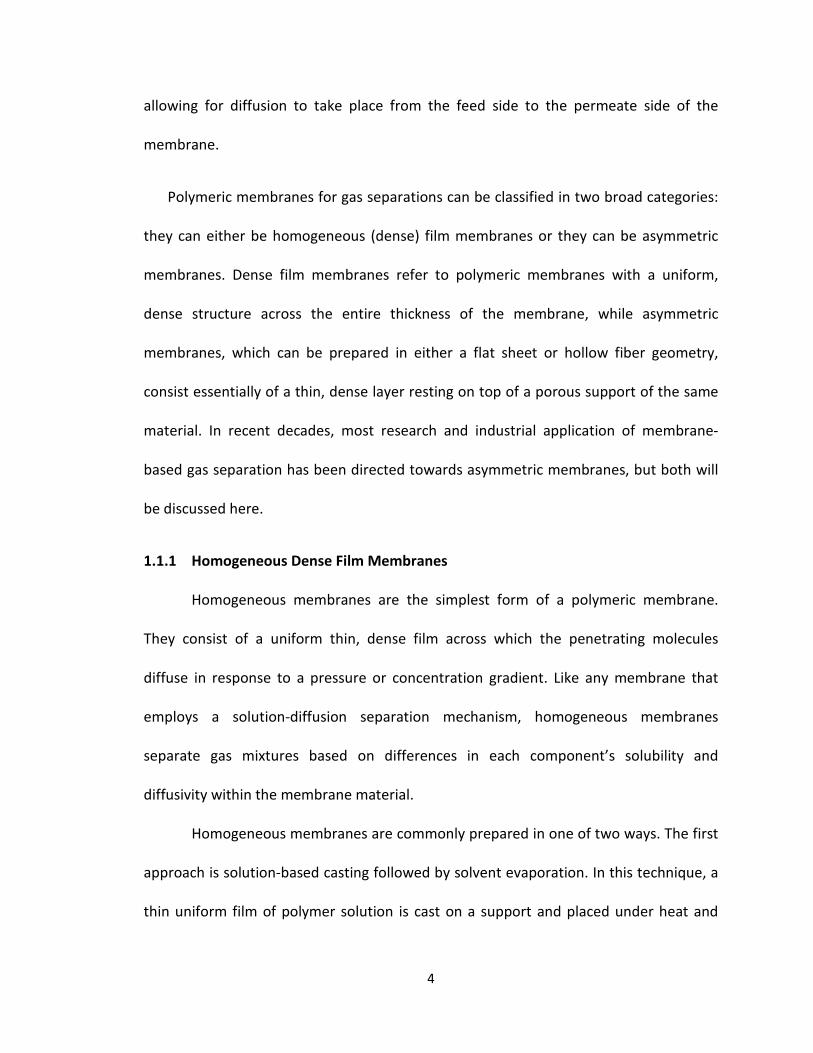
Polymeric membranes for gas separations can be classified in two broad categories:
they can either be homogeneous (dense) film membranes or they can be asymmetric
membranes. Dense film membranes refer to polymeric membranes with a uniform,
dense structure across the entire thickness of the membrane, while asymmetric
membranes, which can be prepared in either a flat sheet or hollow fiber geometry,
consist essentially of a thin, dense layer resting on top of a porous support of the same
material. In recent decades, most research and industrial application of membrane-
based gas separation has been directed towards asymmetric membranes, but both will
be discussed here.
1.1.1 Homogeneous Dense Film Membranes
Homogeneous membranes are the simplest form of a polymeric membrane.
They consist of a uniform thin, dense film across which the penetrating molecules
diffuse in response to a pressure or concentration gradient. Like any membrane that
employs a solution-diffusion separation mechanism, homogeneous membranes
separate gas mixtures based on differences in each component’s solubility and
diffusivity within the membrane material.
Homogeneous membranes are commonly prepared in one of two ways. The first
approach is solution-based casting followed by solvent evaporation. In this technique, a
thin uniform film of polymer solution is cast on a support and placed under heat and
4
vacuum until the solvent is removed and all that remains is a solid thin film of polymer
material. The second method is by extrusion of molten polymer as a solid thin film.
Dense film membranes can be a useful tool for determining the inherent permeability of
a particular gas in the polymer and by extension, the inherent selectivity for various
potential gas pairs. However, due to their relative thickness, dense film membranes
produce gas fluxes that are too low for practical purposes. Therefore, dense film
membranes can only be useful if they (a) are composed of a highly permeable polymeric
material, such as silicone, or (b) are cast at a very low thickness. Free-standing, dense
membranes are often impractical, owing to durability issues [7].
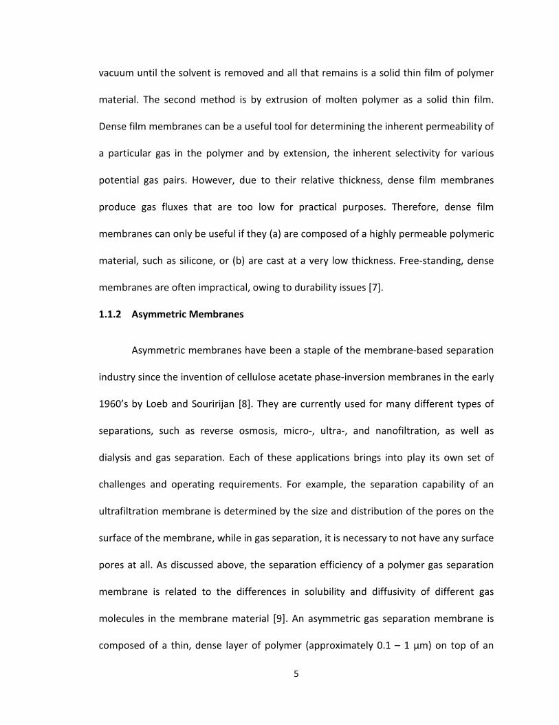
1.1.2 Asymmetric Membranes
Asymmetric membranes have been a staple of the membrane-based separation
industry since the invention of cellulose acetate phase-inversion membranes in the early
1960’s by Loeb and Souririjan [8]. They are currently used for many different types of
separations, such as reverse osmosis, micro-, ultra-, and nanofiltration, as well as
dialysis and gas separation. Each of these applications brings into play its own set of
challenges and operating requirements. For example, the separation capability of an
ultrafiltration membrane is determined by the size and distribution of the pores on the
surface of the membrane, while in gas separation, it is necessary to not have any surface
pores at all. As discussed above, the separation efficiency of a polymer gas separation
membrane is related to the differences in solubility and diffusivity of different gas
molecules in the membrane material [9]. An asymmetric gas separation membrane is
composed of a thin, dense layer of polymer (approximately 0.1 – 1 µm) on top of an
5

open, porous sublayer (100 - 200 µm) of the same material, as shown in Figure 1.2. The
dense layer is the component of the membrane where all of the separation takes place,
as it acts as an ultrathin, homogeneous dense film membrane in its own right, while the
underlying porous layer acts solely as mechanical support. The asymmetric membrane
morphology provides an enormous advantage over dense homogeneous membranes, as
it allows for the dense component of the membrane to be much thinner without
sacrificing structural integrity or selectivity. As a result, much higher gas flux can be
achieved, thereby increasing the membrane capacity. This dramatic improvement in
performance is what allowed membrane technology to begin to compete with other
established separation technologies, such as cryogenic distillation, absorption, and
adsorption in the 1980’s [10].
The primary method of fabrication of asymmetric membranes is by phase
inversion of a polymer solution. There are four common techniques for the fabrication
of membranes via phase inversion. The first is thermally-induced phase separation
(TIPS) [11, 12]. This method relies on the fact that polymers typically become less
soluble in solvents as temperature decreases. Demixing is induced by lowering the
temperature of the solution until precipitation occurs. After demixing, the solvent can
A
B Figure 1.2: Schematic representation of an asymmetric flat sheet membrane. (A) ~0.1-1 µm thick dense layer, where gas separation occurs via solution diffusion (B) ~100-200 µm thick porous layer, which provides mechanical support.
6

be removed by either solvent extraction, evaporation, or freeze-drying. The second
method for inducing phase inversion is air-casting. This process involves dissolving the
polymer in a mixture of a more volatile solvent and a less volatile solvent [13, 14]. The
volatile solvent is then allowed to evaporate, which lowers the solubility of the polymer
in the solution, causing phase separation. The final two methods both involve exposing
a polymer solution (dope) to a substance (non-solvent) in which the solvent is miscible
but the polymer is immiscible. The third method for inducing phase separation, vapor
phase precipitation, involves phase separation caused by non-solvent vapor penetrating
into the solution and lowering the polymer solubility. The fourth method for inducing
phase separation, and the method that will receive the most in-depth discussion here, is
immersion precipitation.
In the immersion precipitation method, a polymer solution is cast into a thin film
or extruded as a hollow fiber and is subject to phase inversion by immersion into a liquid
non-solvent bath. This method of phase separation is more complex than methods such
as TIPS or air-casting as it takes place in a ternary system with multiple simultaneous
diffusion and convection processes operative during membrane formation. The
interactions between the three components of the casting system (polymer, solvent,
nonsolvent) are generally represented using a ternary phase diagram; a generalized
version of a ternary phase diagram for membrane casting is shown in Figure 1.3.
7

When a polymer dope is immersed in a non-solvent bath, the solution separates into
two phases, one polymer-rich and one polymer-lean. There are three general
possibilities for the morphologies that can evolve during phase separation. Two of these
phase separation mechanisms involve the nucleation and growth of one phase within a
matrix of another. Nucleation and growth occurs when the composition of the polymer
solution (dope) moves from a thermodynamically stable region into a meta-stable
region. As shown in Figure 1.3, if the path that the composition of the mixture takes
passes below the critical point (where the binodal and spinodal coincide), the formation
of a nodular structure, consisting of a polymer-rich phase nucleating within a matrix of
polymer-lean phase, is observed. This structure is not conducive to membrane
formation. If the path passes through the critical point, only spinodal decomposition
D
C E
Polymer
Solvent Non-Solvent
A
B
E
Figure 1.3: Generic ternary phase diagram between polymer, solvent, and non-solvent. (A) Binodal line, (B) Spinodal line, (C) Critical point, where binodal and spinodal are equal, (D) Meta-stable region, (E) Phase separation paths.
Polymer-rich phasePolymer-lean phase
8
will occur and the morphology will consist solely of an open, porous substructure. This
morphology is also not conducive to the formation of viable gas separation membranes.
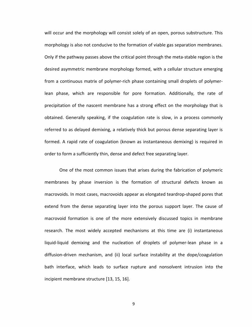
Only if the pathway passes above the critical point through the meta-stable region is the
desired asymmetric membrane morphology formed, with a cellular structure emerging
from a continuous matrix of polymer-rich phase containing small droplets of polymer-
lean phase, which are responsible for pore formation. Additionally, the rate of
precipitation of the nascent membrane has a strong effect on the morphology that is
obtained. Generally speaking, if the coagulation rate is slow, in a process commonly
referred to as delayed demixing, a relatively thick but porous dense separating layer is
formed. A rapid rate of coagulation (known as instantaneous demixing) is required in
order to form a sufficiently thin, dense and defect free separating layer.
One of the most common issues that arises during the fabrication of polymeric
membranes by phase inversion is the formation of structural defects known as
macrovoids. In most cases, macrovoids appear as elongated teardrop-shaped pores that
extend from the dense separating layer into the porous support layer. The cause of
macrovoid formation is one of the more extensively discussed topics in membrane
research. The most widely accepted mechanisms at this time are (i) instantaneous
liquid-liquid demixing and the nucleation of droplets of polymer-lean phase in a
diffusion-driven mechanism, and (ii) local surface instability at the dope/coagulation
bath interface, which leads to surface rupture and nonsolvent intrusion into the
incipient membrane structure [13, 15, 16].
9

1.1.2.1 Flat Sheet Membranes
Asymmetric membranes can be formed in two main geometries; flat sheet or
hollow fiber. Flat sheet membranes are produced by first casting a polymer dope
solution as a thin film onto a substrate. This thin film is then immersed into a bath of
nonsolvent (usually water) or a mixture of solvent and nonsolvent. Both the dope
composition and the composition of the immersion bath are critical in determining the
final morphology of the membrane.
One of the major breakthroughs from the research of Loeb and Sourirajan was
the development of a drying procedure that prevented the pore structure of phase-
inversion cellulose acetate membranes from collapsing due to internal capillary forces
when the membranes were dried [8]. This process was later improved by researchers at
DuPont in the late 1970’s, who added a solvent exchange step to the drying process
[17]. The process that was developed involved removing the residual solvent from the
membrane gradually by first soaking it in deionized water long enough to extract the
solvent. This step was followed by removal of the water using a water miscible, low
boiling point solvent, such as methanol or ethanol [18-21]. The second liquid was then
removed using a more volatile solvent that was miscible with the methanol, but was
immiscible with water. After the methanol was removed from the film with this more
volatile solvent (commonly a hydrocarbon such as pentane or hexane), the solvent was
allowed to evaporate away, resulting in a dry flat sheet membrane with an intact pore
structure.
10

For most practical, large-scale processes, flat sheet membranes are incorporated
into a spiral wound module, wherein the membrane is wrapped around a central
perforated tube and mounted into a module housing. The feed gas mixture is then used
to pressurize the module, with the more permeable gas transported preferentially
across the membrane and out through the tube at the center, while the less permeable
gas exits as retentate. An example of the spiral wound membrane module configuration
is shown in Figure 1.4.
Flat sheet asymmetric membranes were a large leap forward in the field of
membrane technology, as they made it possible for much higher fluxes to be achieved
as compared to traditional dense film membranes, without the drawback of low
structural integrity.
Permeate
Gas Feed
Figure 1.4: Schematic diagram of a spiral wound membrane module.
Retentate
11

1.1.2.2 Hollow Fiber Membranes
Asymmetric hollow fiber membranes (HFM) made from polymeric materials
were first patented by Mahon in 1966 [22]. Hollow fiber membranes possess multiple
features that make them preferable to flat sheet membranes. The hollow fiber
membrane geometry gives a higher surface area to volume ratio, meaning that a higher
effective membrane area can be achieved for a given size membrane module. This leads
to more productive and efficient membrane modules. Hollow fiber membranes also
benefit from a self-supporting structure, rendering them much easier to handle during
membrane formation and module fabrication.
Hollow fiber membranes are fabricated using a method similar to that of
solution spun solid fibers; a generalized schematic of the dry-jet wet spinning process is
shown in Figure 1.5. During HFM spinning, the polymer dope solution is metered
through an annular spinneret using precise syringe pumps, with a suitable bore fluid
metered down the center of the dope through a concentric needle. The nascent fiber
then passes through an air gap, where solvent evaporation begins at the dope/air
interface and phase inversion begins at the dope/bore interface. Finally, the fiber is
immersed in the main coagulation bath (usually composed of water), where phase
inversion on the outer wall of the fiber takes place. Once phase inversion is completed,
the fiber is taken up out of the bath and wound onto a spool with a water wash. Upon
completion of fiber spinning, the residual solvent is removed from the fiber using the
12
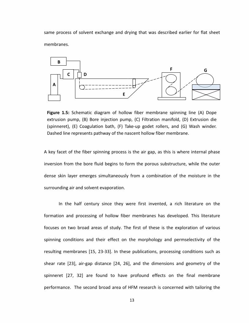
same process of solvent exchange and drying that was described earlier for flat sheet
membranes.
A key facet of the fiber spinning process is the air gap, as this is where internal phase
inversion from the bore fluid begins to form the porous substructure, while the outer
dense skin layer emerges simultaneously from a combination of the moisture in the
surrounding air and solvent evaporation.
In the half century since they were first invented, a rich literature on the
formation and processing of hollow fiber membranes has developed. This literature
focuses on two broad areas of study. The first of these is the exploration of various
spinning conditions and their effect on the morphology and permselectivity of the
resulting membranes [15, 23-33]. In these publications, processing conditions such as
shear rate [23], air-gap distance [24, 26], and the dimensions and geometry of the
spinneret [27, 32] are found to have profound effects on the final membrane
performance. The second broad area of HFM research is concerned with tailoring the
C
B
A
D
E
F G
Figure 1.5: Schematic diagram of hollow fiber membrane spinning line (A) Dope extrusion pump, (B) Bore injection pump, (C) Filtration manifold, (D) Extrusion die (spinneret), (E) Coagulation bath, (F) Take-up godet rollers, and (G) Wash winder. Dashed line represents pathway of the nascent hollow fiber membrane.
13

dope formulation in such a way as to (a) minimize the thickness of the dense separating
layer while maintaining its integrity, and/or (b) alter the physicochemical properties of
the final membrane to improve its overall performance [34, 35]. Some of these methods
include (but are not limited to) (i) adding nonsolvent additives to the dope in order to
tailor the starting point on the ternary phase diagram, (ii) adding volatile solvent
additives, which will be further discussed in the next section, and (iii) the dispersion of
inorganic additives into the polymer matrix of the membrane to form a mixed matrix
membrane (MMM), which will be discussed in Section 1.3.5.
In many respects, hollow fiber membrane development focuses on identifying
casting conditions and dope formulations that produce high-quality flat sheet
membranes and applying these to the fabrication of hollow fiber membranes [36]. This
provides additional challenges, as the formation mechanism is more complex for HFMs
than for flat sheet membranes, and the process conditions that control structure and
performance are quite different for HFMs than for flat sheet. One of the primary
differences is the presence of two simultaneous coagulation fronts in HFM spinning.
When casting a flat sheet membrane, phase-inversion begins at the top surface of the
cast film when it is immersed in the coagulation bath, making it fairly easy to control the
morphology of the membrane. Hollow fiber fabrication, on the other hand, involves
both an internal and external coagulant, each of which controls different parts of the
emerging membrane structure. The internal (bore) coagulant controls the morphology
of the inner skin of the membrane and much of the porous substructure, while the
outer coagulant (along with the air gap) controls the dense separating layer.
14

Additionally, flat sheet membranes allow much greater control of solvent evaporation
prior to phase inversion, as the nature of air-gap spinning allows for only very short
times between dope extrusion and contact with the coagulation bath. Further, in HFM
spinning, the polymer solution is typically flowing extensionally in the gap as it is
accelerated towards the coagulation bath. Cast flat sheet polymer solutions are largely
quiescent during phase inversion.
1.1.2.3 Pinhole Defects and Caulking
One of the main issues that arises during the production of asymmetric membranes
is the formation of pinhole defects in the dense skin separating layer during phase
inversion. These defects are caused by imperfect packing of the polymer chains during
phase separation and dramatically reduce the overall performance of the membrane by
changing the gas transport mechanism from solution diffusion across the dense skin to
Knudsen diffusion through the pinhole channels. This change in diffusion mechanism
causes a dramatic loss in selectivity, since Knudsen diffusion only provides a selectivity
value that is approximately equal to the inverse of the square root of the ratio of the
molecular weights of the constituent gases. With the constant effort to make thinner
dense selective layers, the mitigation of pinhole defects becomes ever more important
[36].
There are multiple ways to address the question of how to best mitigate the effect
of pinhole defects in the dense skin layer of an asymmetric membrane. The simplest
answer to the question, but the most difficult to actually achieve in practice, is to
15

prevent pinhole defects from forming in the first place. Much research has gone into
trying to cast (or spin) membrane materials with a defect-free, ultrathin dense selective
layer [21, 37-41]. One of the primary methods involves the use of a mixture of solvents,
one volatile and one non-volatile, during dope formulation. The addition of a more
volatile solvent to the dope causes a more rapid formation of the dense layer in the air
gap for hollow fiber membranes (or prior to immersion, in the case of flat sheet
membranes) [42]. This method has been fairly well developed, but it is far from perfect,
and defects often can still form in the membrane dense layer.
When a membrane is found to have pinhole defects, usually indicated by the
exhibition of Knudsen selectivity between gas pairs, the primary method for mitigating
these defects is by coating the membrane with a high permeability/low selectivity
material, essentially “caulking” the membrane. The resulting membrane is commonly
referred to as a composite membrane [43-46]. The most common polymer that is used
in this process is polydimethylsiloxane (PDMS), due to it being one of the most
permeable polymers in existence. This process mitigates the effect of pinhole defects by
changing the diffusion mechanism within the channels from Knudsen diffusion to
solution diffusion. The theory describing transport across composite membranes was
first proposed in 1981 by Henis and Tripodi [47]. They introduced the idea of quantifying
the transport properties of these membranes using a resistance model.
16

As shown in Figure 1.6, the model explains the behavior of a composite gas separation
membrane using an analogy with electrical current flow through four resistors. Resistors
with resistances R1 and R4 are connected in series with two resistors, R2 and R3, which
are connected in parallel to each other. R1 is the diffusion resistance offered by the
composite coating of the membrane, R2 is the resistance of the polymer dense layer, R3
the resistance in the defects or pinholes, and R4 is the resistance of the porous
substructure of the membrane. This model allows for the ability to predict the
separation properties of a composite membrane and has been demonstrated to work in
practice to a reasonable degree of accuracy.
1.2 Gas Separation
While the first instance of a polymeric membrane material showing selective
permeation of one gas over another dates as far back as the 1830’s, commercially viable
gas separation membranes did not really emerge until the 1960’s. Prior to the
pioneering efforts of Loeb and Sourirajan, the field faced serious issues with achieving
useful process volumes on a commercial scale. Most attempts to tackle these issues
R2 R3
PDMS Caulk Dense Separating Layer
Porous Support Layer
R2
R4R4
Figure 1.6: Schematic diagram of a porous asymmetric composite membrane (left), along with the electrical resistance analog (right)
R3 R1 R1
17

were primarily aimed at reducing the thickness of a dense film membrane, which led to
greater challenges with both an increase in pinhole formation as well as a decrease in
the durability of the membrane. In 1970, the asymmetric membrane that Loeb and
Sourirajan pioneered for reverse osmosis was finally found to have a gas separation
application. The key innovation that came at this time was the ability to transform the
membrane from a wet state, as is required for reverse osmosis, to a dry state, as is
needed for gas separation, without collapsing the porous support structure [48]. This
was achieved using a surfactant-aided solvent exchange and drying procedure. Early gas
separation applications relied primarily on flat sheet membranes, but these became less
and less common as the technology for asymmetric hollow fiber membranes was
established. One of the most well-known of these HFM separators was the Prism®
system, based on a polysulfone HFM coated with poly(dimethylsiloxane) (PDMS, or
silicone rubber), which was developed by Monsanto (later Air Products) in the late
1970’s. These membranes were an additional step forward for the industry, as the
solvent exchange and drying procedure for a hydrophobic polymer such as polysulfone
was not nearly as tedious and time-consuming as that of the more hydrophilic cellulose
acetate membrane. Additionally, polysulfone was chosen for its commercial availability,
adequate permselectivity, and easy processability. The strong performance that was
exhibited by the Prism® system and other Monsanto products boosted confidence in
membrane based gas separators and paved the way for extensive development of the
technology from companies such as Dow, DuPont, and Air Products in the 1980’s and
continuing into the present day.
18

1.2.1 Equations and Terminology for Gas Separations
Before proceeding too far into the details of specific gas separations, it is
necessary to discuss the important terms and basic equations that are used to
characterize membrane transport performance. The specifics of the derivation of these
equations can be found elsewhere [49]. In most cases, membranes are characterized
primarily by two factors, (a) how readily desired gases flow through the membrane (i.e.
permeability) and (b) how effective the membrane is at rejecting specific components
from the permeate stream (i.e. selectivity).
1.2.1.1 Permeability Coefficient and Permeance
The permeability coefficient (PA) for a particular gas A describes how quickly gas A can
flow through a particular membrane material, normalized by the thickness of the
membrane and the applied pressure drop across the membrane. It is expressed by the
equation:
P𝐴𝐴 = 𝐽𝐽𝐴𝐴𝑙𝑙𝛥𝛥𝛥𝛥
Where JA is the steady-state flux of gas component A across the membrane, l is the
membrane thickness, and ΔP is the trans-membrane pressure difference. PA is generally
viewed as a material property that is not dependent on membrane thickness or pressure
drop and is normally expressed in units of Barrer, where:
1 𝐵𝐵𝐵𝐵𝐵𝐵𝐵𝐵𝐵𝐵𝐵𝐵 = 10−10𝑐𝑐𝑐𝑐3(𝑆𝑆𝑆𝑆𝑆𝑆)𝑐𝑐𝑐𝑐
𝑐𝑐𝑐𝑐2𝑠𝑠 𝑐𝑐𝑐𝑐𝑐𝑐𝑐𝑐
[1.1]
19
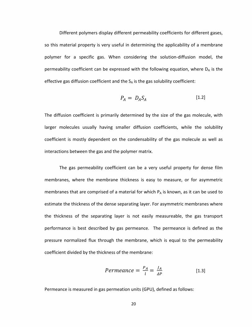
Different polymers display different permeability coefficients for different gases,
so this material property is very useful in determining the applicability of a membrane
polymer for a specific gas. When considering the solution-diffusion model, the
permeability coefficient can be expressed with the following equation, where DA is the
effective gas diffusion coefficient and the SA is the gas solubility coefficient:
𝑆𝑆𝐴𝐴 = 𝐷𝐷𝐴𝐴𝑆𝑆𝐴𝐴
The diffusion coefficient is primarily determined by the size of the gas molecule, with
larger molecules usually having smaller diffusion coefficients, while the solubility
coefficient is mostly dependent on the condensability of the gas molecule as well as
interactions between the gas and the polymer matrix.
The gas permeability coefficient can be a very useful property for dense film
membranes, where the membrane thickness is easy to measure, or for asymmetric
membranes that are comprised of a material for which PA is known, as it can be used to
estimate the thickness of the dense separating layer. For asymmetric membranes where
the thickness of the separating layer is not easily measureable, the gas transport
performance is best described by gas permeance. The permeance is defined as the
pressure normalized flux through the membrane, which is equal to the permeability
coefficient divided by the thickness of the membrane:
𝑆𝑆𝐵𝐵𝐵𝐵𝑐𝑐𝐵𝐵𝐵𝐵𝑃𝑃𝑐𝑐𝐵𝐵 = 𝛥𝛥𝐴𝐴𝑙𝑙
= 𝐽𝐽𝐴𝐴𝛥𝛥𝛥𝛥
Permeance is measured in gas permeation units (GPU), defined as follows:
[1.2]
[1.3]
20
1 𝐺𝐺𝑆𝑆𝐺𝐺 = 10−6𝑐𝑐𝑐𝑐3(𝑆𝑆𝑆𝑆𝑆𝑆)𝑐𝑐𝑐𝑐2 𝑠𝑠 𝑐𝑐𝑐𝑐 𝑐𝑐𝑐𝑐
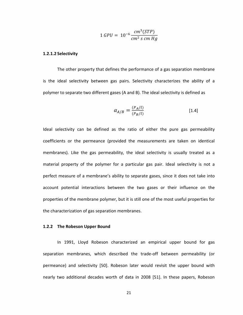
1.2.1.2 Selectivity
The other property that defines the performance of a gas separation membrane
is the ideal selectivity between gas pairs. Selectivity characterizes the ability of a
polymer to separate two different gases (A and B). The ideal selectivity is defined as
𝛼𝛼𝐴𝐴/𝐵𝐵 = (𝛥𝛥𝐴𝐴/𝑙𝑙)(𝛥𝛥𝐵𝐵/𝑙𝑙)
Ideal selectivity can be defined as the ratio of either the pure gas permeability
coefficients or the permeance (provided the measurements are taken on identical
membranes). Like the gas permeability, the ideal selectivity is usually treated as a
material property of the polymer for a particular gas pair. Ideal selectivity is not a
perfect measure of a membrane’s ability to separate gases, since it does not take into
account potential interactions between the two gases or their influence on the
properties of the membrane polymer, but it is still one of the most useful properties for
the characterization of gas separation membranes.
1.2.2 The Robeson Upper Bound
In 1991, Lloyd Robeson characterized an empirical upper bound for gas
separation membranes, which described the trade-off between permeability (or
permeance) and selectivity [50]. Robeson later would revisit the upper bound with
nearly two additional decades worth of data in 2008 [51]. In these papers, Robeson
[1.4]
21

analyzed literature results encompassing a wide range of polymeric membranes in order
to fully characterize the inverse relationship between the permeability and selectivity
for various gas pairs that involve the common gases of H2, O2, N2, CH4, and CO2. This
analysis revealed an upper bound to the relationship, which can be represented on a
log-log plot of selectivity (αij)versus permeability (Pi) of the faster gas, as shown in Figure
1.7. As demonstrated by Robeson’s analysis of the existing literature, virtually no values
(i.e. membrane materials) could be found to exist above the upper bound. The upper
bound was determined to be a straight line, following the relationship:
𝑆𝑆𝑖𝑖 = 𝑘𝑘𝛼𝛼𝑖𝑖𝑖𝑖𝑛𝑛
where the slope (n) of the line is related to the ratio of the Lennard-Jones kinetic
diameters of the gases to be separated.
Figure 1.7: Schematic plot of the Robeson upper bound relationship between membrane efficiency (selectivity) and throughput (permeability) [50].
Log(Permeability)
Log(
Sele
ctiv
ity)
[1.5]
22

From these results, Robeson concluded that the diffusion coefficient was the primary
characteristic that governed the membrane separation capability for the gases in
question, but also acknowledged that for more condensable gases at higher pressure,
the solubility coefficient also plays a role in gas selectivity and permeability. This review
was revolutionary in the sense that it gave a quantitative characterization to a well-
known trade-off relationship between the permeability and selectivity of gases and set a
goal for future gas separation membrane researchers to exceed the Robeson upper
bound.
1.2.3 Air Separation
Membrane-based gas separators can be applied to separate many different feed
streams, and two specific examples will be discussed here, as they are two of the most
commercially relevant separations. The first of these is the separation of air into a
nitrogen enriched component and an oxygen enriched component. The relative
permeabilities of the gas constituents of air (namely O2, N2, and Ar) in rubber were first
characterized by Lord Rayleigh [52]. Since the 1980’s, the field has shown rapid
expansion, led by companies such as Permea and Dow in the United States, as well as
Linde in Germany and Air Products in Norway.
Traditional methods for producing N2 and O2 from air include cryogenic
distillation and pressure-swing adsorption. Cryogenic distillation works in a similar
manner to traditional distillation, but using much lower temperatures. This process
involves lowering the temperature of air until it liquefies, then separating the
23

components based on their boiling points [53]. This process can be used to produce
ultrapure N2 and O2, but is highly energy intensive and requires large amounts of capital
to install and operate. Pressure swing adsorption (PSA) is a process that, unlike
cryogenic distillation, can be operated at ambient temperatures. In this process, air is
pressurized and gases are separated based on their affinity for an adsorbent material,
such as a zeolite. Since it operates at ambient temperatures, PSA provides a significant
reduction in both energy and capital costs over cryogenic distillation.
The similar physical properties of N2 and O2 lead to fairly low membrane
selectivity, compared with other gas separations, such as H2/CO2. However, membrane
based air separation is now generally seen as favorable over conventional methods for
air separation, such as cryogenic distillation and pressure swing adsorption, primarily
because of its lower energy consumption and operating costs. Membrane processes can
be used to produce nitrogen enriched streams of over 95% N2 and oxygen enriched
streams of 60-80% O2, which are both adequate for most commercial uses of those
gases, as discussed further, below.
1.2.3.1 Nitrogen Enriched Air (NEA)
Since O2 is the gas that permeates faster through most polymeric membranes,
oxygen enriched air (OEA) is usually collected at low recovery in the permeate stream,
while nitrogen enriched air (NEA) is collected at higher recovery in the retentate stream.
In order to maximize N2 product recovery and product purity while also reducing capital
costs, air is generally separated using a multistage membrane system with a recycle
24

step. In this system, the retentate from the first membrane unit is fed into a second
membrane unit, with the permeate stream from the second unit being compressed and
recycled back into the original feed stream. This type of system can produce very high
concentrations of N2 (>99%) at very low recovery using membranes with selectivity as
low as 2. In order to recover enough NEA at high concentrations for most practical
purposes however, an O2/N2 selectivity of approximately 6 or greater is needed.
Nitrogen enriched air produced by membrane-based air separation is used for a
variety of purposes in the fields of oil and gas, chemicals and electronics, among others.
It is very commonly used as an inerting agent in aircraft fuel tanks in order to reduce
exposure to flammable vapors. NEA is also widely used in food storage in order to
extend the shelf life of food and reduce spoilage by preventing bacterial growth and
eliminating moisture. Additionally, tires filled with NEA rather than air tend to lose
pressure at a slower rate, due to the slower transport of nitrogen through the tire walls.
1.2.3.2 Oxygen Enriched Air (OEA)
The ability to produce O2 from air using membrane based methods has been
studied for decades. Initial attempts to produce oxygen enriched air (OEA) were aimed
at using PDMS membranes, because of their high O2 permeability in combination with
modest O2/N2 selectivity. It wasn’t until higher selectivity was achieved (while
maintaining high permeability) that the technology began to replace pressure-swing
adsorption as the dominant method for OEA production. Currently, the top-of-the-line
commercial O2/N2 membranes have an ideal selectivity in the range of 8-10 with a
25

permeability coefficient on the order of 1 Barrer [51]. While this selectivity is reasonably
high, the scope of the industry could be considerably expanded if membrane materials
with selectivity in the range of 15-20, which is beyond the 2008 Robeson upper bound
[51], could be developed at scale. This would allow for the production OEA with above
90% purity, positioning it to rival PSA for more applications.
Oxygen enriched air is most commonly used in combustion-based processes as a
way to increase the O2 content of a reacting fuel-oxidizer mixture, which leads to large
improvements in both burn rates and fuel efficiency. For example, when OEA is used as
the feed in a power plant, it reduces the amount of N2 in the flue gas, thereby
eliminating a difficult (and expensive) CO2/N2 separation that is necessary for CO2
capture and sequestration. OEA also has the effect of increasing the heating rate and
reducing the fuel consumption. Other advantages to using OEA for combustion include a
reduction in smoke volume, ignition point of the fuel, and burnout times as well as an
increase in heat utilization and radiation heat transfer.
On a smaller scale, OEA has other uses, such as treatment for hypoxia and
altitude sickness that are commonly suffered by people who travel to higher altitude
areas. A membrane-based OEA production system has the advantage of providing
oxygen to someone suffering from altitude sickness, or chronic pulmonary conditions,
without the use of a cumbersome and potentially dangerous pressurized oxygen tank.
Oxygen enrichment technology can also be used in sleeping tents to improve exercise
26

performance, provide OEA to aircraft passengers to combat hypoxia, and in some cases,
purely for recreational use [52].
1.2.4 Natural Gas Purification
Natural gas contains mostly methane (CH4), but it also contains several
impurities, such as carbon dioxide (CO2), nitrogen (N2), hydrogen sulfide (H2S), water
(H2O), and various heavy hydrocarbons. Each of these impurity concentrations must be
reduced in the gas stream in order to meet pipeline specifications by the Federal Energy
Regulatory Commission (FERC) [54]. The removal of CO2 in particular is very important,
as it corrodes pipelines, lowers the heating value of the natural gas, and increases the
costs associated with compression of the gas. The most commonly used method for
removal of natural gas pollutants is amine gas treatment (also called amine scrubbing,
gas sweetening, and acid gas removal) [55]. In this process, raw natural gas is passed
through an amine solution, usually monoethanol amine (MEA) or diethanol amine
(DEA), which absorbs acid gases (H2S and CO2). This method works very well, but has the
disadvantages of high operating costs as well as the necessity of special materials for
equipment construction in order to mitigate corrosion. The primary advantage that
amine scrubbing has traditionally held over membrane-based separation is the ability to
handle higher volumes and gas streams with extraordinarily high CO2 content. Amine
scrubbing also has the ability to meet standards for CO2 removal to the ppm level,
whereas membrane-based separators struggle to produce gas streams with below 2%
CO2 [56]. Advances in membrane technology over the past two decades have begun to
27
make membranes competitive with amine absorption [57]. As with air separation, the
primary advantage to using membrane-based separation is cost. Membrane-based
separator systems tend to have very low installation, operating, and maintenance cost,
as well as lower energy consumption during operation. These improvements are
generally attributed to the fact that membrane separations do not require a change of
phase.
The first demonstrations of acid gas removal from natural gas feed streams using
membranes date back to the late 1960’s, with the asymmetric cellulose acetate
membrane that was developed by Loeb and Sourirajan. These early membranes showed
actual selectivities that were much lower than the ideal pure gas selectivity of the gases
due to the effects of plasticization caused primarily by CO2. Plasticization occurs when
the concentration of CO2 is high enough to increase the free volume and mobility of the
polymer molecules, which causes the polymer matrix to swell with an accompanying
loss of selectivity. This effect can be characterized by a decrease in the glass transition
temperature (Tg) of the polymer. Various strategies have been explored to mitigate
plasticization in hollow fiber membranes, for example through the use of crosslinked
CO2-resistant polyimides [58] or polyamides [59].
Another contaminant of natural gas streams that must be removed is nitrogen.
Nitrogen lowers the BTU value of natural gas and must be below a certain level for sale
to a pipeline. N2 can be separated from natural gas using membranes to produce both
pipeline-quality gas and a nitrogen-rich retentate stream. Traditional methods for
28

removing nitrogen from natural gas feeds include cryogenic distillation and pressure-
swing adsorption, similar to air separation. As with air separation, membrane-based
separation methods offer both a lower capital cost as well as a lower energy cost. This is
an area of active research.
1.3 Relevant Membrane Polymers of Interest
1.3.1 Cellulose Acetate (CA)
Cellulose acetate (CA) was one of the first polymeric membrane materials to be
used for natural gas separation applications [48]. It was originally developed for water
desalination [60-62], but with the invention of asymmetric phase inversion membranes
by Loeb and Sourirajan, as discussed earlier [8], CA became a viable membrane for gas
separations as well. Since then, it has been used commercially for multiple gas
separations, but it is most effectively used for the removal of acid gases from natural gas
and the separation of CO2 from hydrocarbons. The main advantage that CA membranes
have over other commercial membranes is their low cost. They can be made cheaply,
mostly because raw cellulose is both abundant and renewable. Additionally, since CA
membranes have been around so long, the kinetics and thermodynamics governing
their formation are very well understood [13, 14], ensuring that they can be easily
fabricated.
There are two main drawbacks to the use of cellulose acetate for gas
separations. The first is that it is far from the most efficient polymer for most
applications, with gas performance characteristics (i.e. selectivity; permeability) that lie
29
well below the Robeson upper bound. The other main drawback to the use of CA is that
it is very susceptible to CO2-induced plasticization. This effect causes the CA membrane
to lose selectivity in mixed gas environments at high partial pressures of CO2. Because of
these issues, the separation capability of CA is heavily dependent on feed pressure and
composition, and thus most research, both commercial and academic, has been focused
on other material platforms for gas separations, such as the ones that will be discussed
in the following sections.
1.3.2 Poly(aryl ether sulfones)
The poly(aryl ether sulfones) are a class of thermoplastic polymers characterized
as having a diphenylene sulfone backbone (-Ar-SO2-Ar), and they include some of the
most commonly used commercial membrane polymers for a wide range of applications
[63-67]; see the repeat structures in Figure 1.8. Polysulfones have emerged as an
important class of membrane polymers primarily due to their outstanding mechanical
strength, dimensiona l stability, and exceptional thermal and chemical resistance.
30

Polyethersulfone (PES) has been used in ultrafiltration and gas separations for
decades and readily forms asymmetric membranes via phase inversion, either as a flat
sheet or a hollow fiber [68]. PES is a very commonly used polymer in membrane
fabrication due to its relatively low cost as compared to other membrane polymers.
However, PES is also susceptible to fouling during water filtration due to its high
hydrophobicity. Because of this, there has been an emphasis on modification of PES
membranes via polymer blending, surface modification [69, 70], and addition of
inorganic fillers to form mixed matrix membranes (MMM) [71-73].
Figure 1.8: Polymer repeat unit for (A) polyethersulfone (PES), (B) polysulfone (PSf), and (C) polydimethylsiloxane (PDMS).
S
O
O
O
n
n
O SO
O
A
B
C
Si
CH3 CH3
O On
31

Numerous studies have been conducted by Chung et al., exploring the influence
of various spinning parameters on the morphology and separation performance of PES
hollow fiber membranes [23, 24, 28-30, 32, 65, 74]. These studies include investigations
into the effects of air gap distance, spinning temperature, and dope shear rate within
the spinneret on the membrane morphology and performance. Much of this research
focuses on the formation of macrovoids in PES membranes [15]. Macrovoids are large
defects that form during phase inversion. While they do not completely ruin the
performance of a membrane, it is often beneficial to avoid the formation of macrovoids,
as they are structural defects that can result in mechanical failure of the membrane in
high pressure applications.
Polysulfone (PSf) is one of the most commonly used commercial gas separation
membranes, and it is the basis for the Air Products PRISM® membrane system discussed
earlier. Polysulfone has a similar structure to polyethersulfone, but with an additional
bisphenol unit connected by an ether group, as shown in Figure 1.8. This structural
difference in the polysulfone repeat, as compared to polyethersulfone, results in less
efficient packing, leading to a higher fractional free volume in polysulfone and a higher
permeability, while only slightly lowering the selectivity. Polysulfone is widely used for
hydrogen and air separations and has similar proximity to the Robeson upper bound as
other commercial gas separation polymers, such as Matrimid® polyimide.
32

1.3.3 Polyimides
Aromatic polyimides are generally useful as gas separation membranes, as they
tend to have high permeability and high intrinsic selectivity, and also have good physical
properties. In industry, polyimide membranes are used by gas companies Praxair and Air
Liquide for natural gas purification, due to an industry-best combination of CO2
permeability of about 10 Barrer and CO2/CH4 selectivity of 36. Matrimid® is the most
commonly used commercial polyimide, originally developed for use in the electronics
industry, but later found to have gas separation applications as well. Matrimid® is not
only used for its good permselectivity, but it also has exceptional mechanical strength
and high Tg, which make it a preferred choice for high temperature environments. It also
has the advantage of being soluble in common organic solvents, allowing it to be
processed in solution, which is necessary for asymmetric membrane fabrication. The
main drawback of Matrimid® is that, like cellulose acetate, it is susceptible to CO2-
induced plasticization at high pressures.
One of the most effective strategies to improve the gas permeability (particularly
CO2) in aromatic polyimide materials and combat CO2-induced plasticization is thermal
rearrangement (TR) [75-79]. Thermal rearrangement changes the backbone structure of
the membrane from an aromatic polyimide containing hydroxyl groups ortho to the
imide ring into a thermally-resistant polybenzoxazole (PBO) by heating the polymer to a
high temperature (> 400°C) in an inert atmosphere, as shown in Figure 1.9.
33
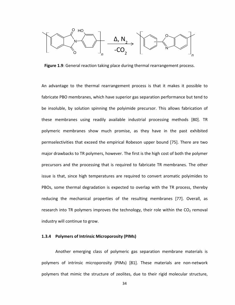
An advantage to the thermal rearrangement process is that it makes it possible to
fabricate PBO membranes, which have superior gas separation performance but tend to
be insoluble, by solution spinning the polyimide precursor. This allows fabrication of
these membranes using readily available industrial processing methods [80]. TR
polymeric membranes show much promise, as they have in the past exhibited
permselectivities that exceed the empirical Robeson upper bound [75]. There are two
major drawbacks to TR polymers, however. The first is the high cost of both the polymer
precursors and the processing that is required to fabricate TR membranes. The other
issue is that, since high temperatures are required to convert aromatic polyimides to
PBOs, some thermal degradation is expected to overlap with the TR process, thereby
reducing the mechanical properties of the resulting membranes [77]. Overall, as
research into TR polymers improves the technology, their role within the CO2 removal
industry will continue to grow.
1.3.4 Polymers of Intrinsic Microporosity (PIMs)
Another emerging class of polymeric gas separation membrane materials is
polymers of intrinsic microporosity (PIMs) [81]. These materials are non-network
polymers that mimic the structure of zeolites, due to their rigid molecular structure,
Figure 1.9: General reaction taking place during thermal rearrangement process.
N
O
O
OHO
Nn n
Δ, N2
-CO2
34

which prevents efficient packing of the polymer chains in the solid state. They were first
developed by Budd et al. in the early 2000’s [82-84]. The microporosity of these
polymers is described as intrinsic, because it is derived solely from their molecular
structure and not from any processing history of the material. An example of the
molecular synthesis and structure of PIM-1, one of the most commonly used PIMs, is
shown in Figure 1.10.
The two main reactants that are required for this synthesis are an aromatic tetrol and a
halogen containing monomer. As the figure shows, the spirocyclic feature of the
precursor molecule leads to a contorted confirmation and the formation of a
dibenzodioxane ladder structure, which then results in a rigid backbone in the final
polymer, which has no rotational freedom but also has a randomly assorted molecular
structure.
There are two main drawbacks to PIMs. The first is that, while the aromatic
tetrol precursor is readily available at the commercial level, the required aromatic
halides tend to be very expensive and limited in their commercial availability [80].
Additionally, it is often difficult to synthesize PIMs in adequate molecular weights and
yields, which results in difficulty in the formation of thin film membranes and also
OH
OH OH
OH
F
FF
FCN
CN
O
O O
O
CN
CNn
+
Figure 1.10: Preparation of PIM-1 polymer of intrinsic microporosity.
35
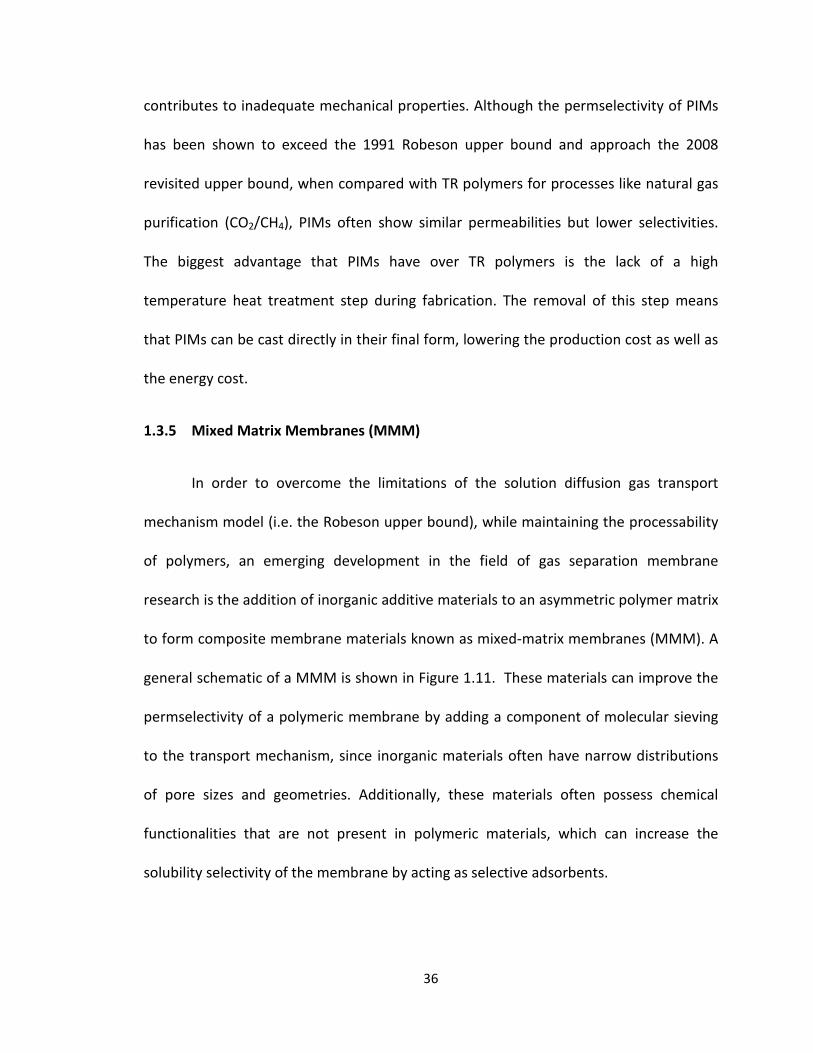
contributes to inadequate mechanical properties. Although the permselectivity of PIMs
has been shown to exceed the 1991 Robeson upper bound and approach the 2008
revisited upper bound, when compared with TR polymers for processes like natural gas
purification (CO2/CH4), PIMs often show similar permeabilities but lower selectivities.
The biggest advantage that PIMs have over TR polymers is the lack of a high
temperature heat treatment step during fabrication. The removal of this step means
that PIMs can be cast directly in their final form, lowering the production cost as well as
the energy cost.
1.3.5 Mixed Matrix Membranes (MMM)
In order to overcome the limitations of the solution diffusion gas transport
mechanism model (i.e. the Robeson upper bound), while maintaining the processability
of polymers, an emerging development in the field of gas separation membrane
research is the addition of inorganic additive materials to an asymmetric polymer matrix
to form composite membrane materials known as mixed-matrix membranes (MMM). A
general schematic of a MMM is shown in Figure 1.11. These materials can improve the
permselectivity of a polymeric membrane by adding a component of molecular sieving
to the transport mechanism, since inorganic materials often have narrow distributions
of pore sizes and geometries. Additionally, these materials often possess chemical
functionalities that are not present in polymeric materials, which can increase the
solubility selectivity of the membrane by acting as selective adsorbents.
36

The first known application of a MMM for gas separation in the literature involved the
dispersion of 5A zeolite into polydimethylsiloxane (PDMS), conducted by Paul and Kemp
in the early 1970’s [85, 86]. In these studies, the researchers discovered that adding the
zeolite to the polymeric matrix caused a large increase in the diffusion time lag, but they
did not observe a significant effect on the steady-state diffusion properties. The first to
report an increase in selectivity due to the addition of an inorganic filler material were
researchers with Honeywell, who observed an increase in O2/N2 selectivity in cellulose
acetate with the addition of silicalite [87]. Since then, a broad range of filler materials
have been observed to improve membrane performance, including zeolites, metal-
organic frameworks (MOFs), and carbon materials, such as carbon molecular sieves or
carbon nanotubes [88].
1.3.5.1 Zeolite MMM
Zeolites were the first material to be incorporated as the inorganic filler in a
mixed-matrix membrane and have shown much promise in the field due to their unique
molecular sieving properties. An example of this type of material is described in the
Figure 1.11: Schematic representation of an asymmetric flat sheet mixed matrix membrane. (A) Dense separating layer (B) Porous support layer, (C) Dispersed inorganic filler material, which adds a component of molecular sieving to the solution diffusion mechanism.
A
B
C
37
work by Kulprathipanja et al [72]. In this work, microporous and nanoporous zeolite 4A
was dispersed in a matrix of polyethersulfone (PES). The research showed an increase in
selectivity for several gas pairs, including He/N2, O2/N2, and CO2/CH4 for both the micro-
and nanoporous zeolite 4A, but also resulted in a decrease in the permeability
coefficient for all of the gases studied.
Despite their promise, zeolite MMMs still have not gained much commercial
relevance. There are several reasons for this. The first is that zeolites and polymers
often suffer from a lack of interfacial compatibility, which leads to an increase in non-
selective defects at the interface of the zeolite particles and the polymeric matrix. The
other issue that plagues zeolite MMMs is poor mechanical properties, particularly when
dealing with thin films. Other challenges include polymer rigidification, pore blocking,
and the fact that zeolites often adsorb gases to binding sites, which can result in
reduced diffusion for vapors. Because of all of these issues, recent MMM research has
moved away from zeolites and toward metal-organic frameworks and inorganic carbon
based filler materials.
1.3.5.2 Metal Organic Framework (MOF) MMM
While most of the early work in mixed-matrix membranes was focused on zeolite
molecular sieves dispersed in a polymeric matrix, more recent studies of MMMs have
been directed toward a relatively new class of microporous materials with metal organic
frameworks (MOFs) as the inorganic filler material [5, 89-94]. MOFs are comprised of
transition metals or transition metal oxides connected by organic linkages to create
38

microporous structures. These microporous structures can result in extremely high
surface areas, with some reported as high as 10,000 m2/g. Like zeolites, MOFs can be
synthesized quickly, cheaply, and easily. Additionally, MOFs have an enormous range of
variability in composition and structure, with the organic linkages providing a platform
for chemistries that can improve polymer adhesion [5], thereby reducing nonselective
defects that often plague zeolites at the filler-matrix interface. The range of material
variables available in MOF-based mixed matrix membranes can be exploited to produce
a tunable pore structure, mechanical and chemical stability, as well as CO2 plasticization
resistance in some cases.
The most common sub-class of MOFs to be featured in mixed matrix membranes
are zeolitic imidazolate frameworks (ZIFs). ZIFS are usually formed from zinc or cobalt
ions tetrahedrally coordinated to imidazolate linkers. They get their name (zeolitic) due
to the bond angle similarities with zeolites [88]. Within this sub-class, the most
extensively studied for gas separation membrane applications is ZIF-8. In a
crystallographic sense, ZIF-8 has a 3.4 Å pore aperture and 11.6 Å cages [88]. The small
pore aperture gives this material the properties of a molecular sieve with length scales
appropriate for gas separations. Additionally, part of the organic linker of this MOF can
rotate within the pores, creating a flexible gate opening mechanism in the pores that
can allow larger molecules to diffuse through the pore system. For pure gas
measurements, Song, et al. found that ZIF-8/Matrimid® MMMs enhanced the
permeability of H2, CO2, O2, N2, and CH4 without showing any decrease in selectivity, at
loadings as high as 30 wt.% [94]. They have also been applied to hollow fiber
39
membranes for CO2/N2 separations, as demonstrated by Koros et al. [95]. In this work,
17 vol% ZIF-8 was incorporated into a matrix of polyetherimide (Ultem® 1000), which
resulted in an increase in CO2/N2 selectivity from 30 to 36 while also increasing the
permeance of the membrane from 14 GPU to 26 GPU over a neat Ultem hollow fiber
membrane.
Overall, MMMs composed of a polymeric matrix with a metal-organic framework
are an important emerging class of membrane materials for gas separations. This is due
to their relatively low cost, ease of synthesis, accessible range of material variants and
strong adhesion to the polymeric matrix.
1.3.5.3 Carbon Nanotube (CNT) MMM
Since they were first described in detail by Ijima in 1991 [96], carbon nanotubes
(CNT) have been extensively studied for their thermal, electrical and mechanical
properties, as well as their potential utility in membrane applications. For example, in
one early approach, polymeric membranes were configured with aligned carbon
nanotube arrays and used as nanoporous water filtration membranes, as described by
Hinds et al. [97-100]. In more recent years, they have been incorporated as an inorganic
filler material in mixed matrix membranes [71, 90, 92, 101-103]. Although it is
sometimes difficult to get an even dispersion of carbon nanotubes with good adherence
to the polymeric matrix, carbon nanotubes have been found to improve the selectivity
of polysulfone [104], and polyethersulfone [102, 105] membranes for gas separation.
For example, studies by Ismail, et al., explored potential ways to improve the adhesion
40

of carbon nanotubes to the polymeric matrix by functionalizing the nanotube surface.
Using this approach, they were able to increase the O2/N2 ideal selectivity of neat
polyethersulfone from 5.6 to 10.65 at a nanotube loading of 0.5 wt.%. A decrease in
selectivity was observed as the nanotube content was increased further, which the
researchers attributed to an increased presence of interfacial voids. The flat sheet
MMM study by Ismail was extended by Zeinali, et al., who further examined carbon
nanotube pretreatments as well as the effects of the solvent on the morphology and gas
separation properties of the membranes [102]. This study determined that N-
methylpyrrolidone (NMP) was the most effective solvent for the fabrication of flat sheet
mixed matrix membranes, citing improvements in MWCNT distribution and a reduction
in agglomeration as compared to N,N-dimethylacetimide (DMAc). In the hollow fiber
geometry, the addition of multi-wall carbon nanotubes that had been pretreated with
dry air oxidation, (which removed amorphous carbon and catalyst particles), and were
aided in dispersion by the use of Triton X100 surfactant were shown to improve the
permeability of polyetherimide (PEI) without any reduction in selectivity for O2/N2 [106].
Overall, carbon nanotubes represent a promising but relatively unexplored inorganic
filler material for use in mixed matrix membranes, and are of particular interest for
incorporation into hollow fiber membrane systems.
41
1.4 Research Objectives
The research presented in this dissertation was conducted in pursuit of four
broad objectives related to the controlled formulation, processing and characterization
of flat sheet and asymmetric hollow fiber membranes. These objectives were:
1.) To design, fabricate, and commission a fully-functional hollow fiber membrane
spinning line.
2.) To study the phase inversion characteristics of flat sheet membranes to
determine the effects of dope composition (including solvent) and coagulation
medium on membrane morphology.
3.) To investigate hollow fiber processing conditions as they relate to the resulting
dimensions and morphology of hollow fiber membranes.
4.) To examine the effects associated with the inclusion of low levels of nanoscale
inorganic filler materials on the gas transport properties of membranes in both
the flat sheet and hollow fiber membrane geometries.
Prior to this research work, the capacity to produce hollow fiber membranes did not
exist at the University of Kentucky. Accordingly, the first objective pursued was the
design, construction and commissioning of a hollow fiber membrane spinning line for
the controlled production of polymer hollow fiber membranes. This effort was
informed by review of literature and current industrial practice, and drew on extensive
in-house expertise available at the UK Center for Applied Energy Research. The resulting
spin line was designed to provide all necessary control and versatility to accommodate a
wide range of processing rates, formulations and membrane quench conditions.
42
In order to establish appropriate membrane formulations and quench
conditions, the phase inversion characteristics of selected membrane casting systems
were studied in the flat sheet geometry. Specifically, the influence of polymer dope
composition and coagulation medium on membrane morphology was investigated.
These experiments were conducted in order to fully elucidate the morphological
features of the resulting polyethersulfone and polysulfone asymmetric membranes
across a range of casting conditions. While these studies provided foundational
knowledge in the context of the flat sheet geometry, they also informed the
determination of dope composition, bore fluid, and external coagulant for hollow fiber
membrane spinning. When spinning hollow fiber membranes, it is important that the
resulting membrane morphology display a thin, integral dense outer separating layer,
minimal macrovoids, a sponge-like porous support layer, and a porous wall on the
lumen (interior) side of the membrane. This structure results in a gas separation
membrane that exhibits the highest possible permeance without sacrificing selectivity.
The compositions of the dope and the bore fluid play a critical role in achieving the
desired morphology in hollow fiber membranes.
Three key membrane processing parameters were identified that have the
potential to strongly influence the dimensions, morphology and resulting gas separation
characteristics of the hollow fiber membranes prepared in this work. These are: (i) the
ratio of the bore fluid velocity (i.e. flowrate) to the dope velocity at the exit of the
spinneret; (ii) the vertical air gap distance between the spinneret and the coagulation
bath; and (iii) the ratio of the take-up velocity of the solid fiber as compared to the
43

velocity of the dope as it is extruded from the spinneret (i.e. draw down ratio). These
parameters were systematically varied in order to determine their influence on the
dimensions and morphology of the hollow fiber membranes, relative to the desired
morphological features articulated above. Additionally, the experiments were used to
establish a standard set of operating conditions for the hollow fiber spinning of mixed
matrix membrane formulations.
The final objective of this research was to investigate the inclusion of low levels
of nanoscale inorganic filler materials and to assess their influence on the gas transport
properties of polyethersulfone and polysulfone membranes. Of particular interest was
the inclusion of multiwall carbon nanotubes for the creation of mixed matrix
membranes in both the flat sheet and hollow fiber geometries. Utilizing a well-
characterized supply of multi-wall carbon nanotubes synthesized in-house, formulation
strategies were implemented for the production of casting dopes with uniform
nanotube dispersion. The resulting membranes were studied both in terms of their
morphology and corresponding permeation properties. The latter studies required the
development of gas permeation testing equipment, and the establishment of protocols
for the assembly of hollow fiber membrane permeation mini-modules. In addition, post-
processing coating methods were used to remediate the surface defects typically
encountered with as-cast asymmetric membrane structures.
The chapters that follow describe in detail how the objectives were
accomplished. The design and assembly of the hollow fiber membrane spin line, and all
experimental details related to membrane formulation, casting and permeation testing
44

are described in Chapter 2. Chapter 3 presents the results for the flat sheet membrane
experiments, including studies on phase inversion morphology and gas transport for
unfilled polyethersulfone and polysulfone membranes, as well as mixed matrix
membranes based on inclusion of carbon nanotubes and carbon black. Chapter 4
describes hollow fiber membrane processing, including the influence of variations in
feed flowrate, vertical gap distance prior to quench, and take-up rate on fiber
characteristics. In addition, the permeation properties of the hollow fiber membranes
are reported. Finally, Chapter 5 provides a summary of all important conclusions and a
discussion of potential future work.
45

1.5 References
1. Mitchell, J.K., On the penetrativeness of fluids. The Journal of the Royal Institution ofGreat Britain, 1831. 4: p. 101.
2. Ward, T.L., Dao, T., Model of hydrogen permeation behavior in palladium membranes.Journal of Membrane Science, 1999. 153(2): p. 211-231.
3. Uhlhorn, R.J.R., Keizer, K., Burggraaf, A. J., Gas and surface-diffusion in modified gamma-alumina systems. Journal of Membrane Science, 1989. 46(2-3): p. 225-241.
4. Caro, J., Noack, M., Zeolite membranes - Recent developments and progress.Microporous and Mesoporous Materials, 2008. 115(3): p. 215-233.
5. Keskin, S., Liu, J., Rankin, R. B., Progress, opportunities, and challenges for applying atomically detailed modeling to molecular adsorption and transport in metal-organic framework materials. Industrial & Engineering Chemistry Research, 2009. 48: p. 2355-2371.
6. Wijmans, J.G. and R.W. Baker, The solution-diffusion model - a review. Journal ofMembrane Science, 1995. 107(1-2): p. 1-21.
7. B., L. and A.-S. M.N.Z., Fundamentals of Membrane Processes. In: Fundamentals ofMembrane Bioreactors. Springer Transactions in Civil and Environmental Engineering,2017.
8. Loeb, S., Sourirajan, S., Sea water demineralization by means of a semipermeablemembrane. Advances in Chemistry, 1962. 38: p. 117-132.
9. VandeWitte, P., Dijkstra, P. J., VandenBerg, J. W. A., Feijen, J., Phase separationprocesses in polymer solutions in relation to membrane formation. Journal of MembraneScience, 1996. 117(1-2): p. 1-31.
10. Koros, W.J., Fleming, G. K., Membrane-based gas separation. Journal of MembraneScience, 1993. 83(1): p. 1-80.
11. Strathmann, H., Production of microporous media by phase inversion processes. ACSSymposium Series, 1985. 269: p. 165.
12. Strathmann, H., Koch, K., The formation mechanism of phase inversion membranes.Desalination, 1977. 21: p. 241.
13. Zeman, L., Fraser, T., Formation of air-cast cellulose acetate membranes. Part I: Study ofmacrovoid formation. Journal of Membrane Science, 1993. 84: p. 93.
14. Zeman, L., Fraser, T., Formation of air-cast cellulose acetate membranes. Part II: Kineticsof demixing and microvoid growth. Journal of Membrane Science, 1994. 87: p. 267.
15. Peng, N., Chung, T. S., Wang, K. Y., Macrovoid evolution and critical factors to formmacrovoid-free hollow fiber membranes. Journal of Membrane Science, 2008. 318(1-2):p. 363-372.
16. Widjojo, N., Chung, T., Thickness and air gap dependence of macrovoid evolution inphase-inversion asymmetric hollow fiber membranes. Industrial & EngineeringChemistry Product Research and Development, 2006. 45: p. 7618-7626.
17. Manos, P., Solvent drying of cellulose ester membranes, 1978, DuPont: USA, US4068387.
18. Bindal, R.C., Hanra, M. S., Misra, B. M., Novel solvent exchange cum immersionprecipitation technique for the preparation of asymmetric polymeric membrane. Journalof Membrane Science, 1996. 118(1): p. 23-29.
46
19. Bindal, R.C., M.S. Hanra, and B.M. Misra, Novel solvent exchange cum immersionprecipitation technique for the preparation of asymmetric polymeric membrane. Journalof Membrane Science, 1996. 118(1): p. 23-29.
20. Jawad, Z.A., Ahmad, A. L., Low, S. C., Chew, T. L., Zein, S. H. S., Influence of solventexchange time on mixed matrix membrane separation performance for CO2/N2 and akinetic sorption study. Journal of Membrane Science, 2015. 476: p. 590-601.
21. Kurdi, J., Tremblay, A. Y., Preparation of defect-free asymmetric membranes for gasseparations. Journal of Applied Polymer Science, 1999. 73(8): p. 1471-1482.
22. Mahon, H., Permeability separatory apparatus, permeability separatory membraneelement, method of making the same and process utilizing the same. 1966, DowChemical Co, USA ,US3228876.
23. Cao, C., Chung, Tai-Shung, Chen, Shing Bor, Dong, ZhengJun, The study of elongation andshear rates in spinning process and its effect on gas separation performance ofPoly(ether sulfone) (PES) hollow fiber membranes. Chemical Engineering Science, 2004.59(5): p. 1053-1062.
24. Chung, T.S., Hu, X. D., Effect of air-gap distance on the morphology and thermalproperties of polyethersulfone hollow fibers. Journal of Applied Polymer Science, 1997.66(6): p. 1067-1077.
25. Chung, T.S., Kafchinski, E. R., The effects of spinning conditions on asymmetric6FDA/6FDAM polyimide hollow fibers for air separation. Journal of Applied PolymerScience, 1997. 65(8): p. 1555-1569.
26. Chung, T.S., Z.L. Xu, and W.H. Lin, Fundamental understanding of the effect of air-gapdistance on the fabrication of hollow fiber membranes. Journal of Applied PolymerScience, 1999. 72(3): p. 379-395.
27. Peng, N., Chung, T. S., The effects of spinneret dimension and hollow fiber dimension ongas separation performance of ultra-thin defect-free Torlon® hollow fiber membranes.Journal of Membrane Science, 2008. 310(1-2): p. 455-465.
28. Qin, J.J., Gu, J., Chung, T. S., Effect of wet and dry-jet wet spinning on the sheer-inducedorientation during the formation of ultrafiltration hollow fiber membranes. Journal ofMembrane Science, 2001. 182(1-2): p. 57-75.
29. Qin, J.J., R. Wang, and T.S. Chung, Investigation of shear stress effect within a spinnereton flux, separation and thermomechanical properties of hollow fiber ultrafiltrationmembranes. Journal of Membrane Science, 2000. 175(2): p. 197-213.
30. Wang, K.Y., Matsuura, T., Chung, T. S., Guo, W. F., The effects of flow angle and shearrate within the spinneret on the separation performance of poly (ethersulfone) (PES)ultrafiltration hollow fiber membranes. Journal of Membrane Science, 2004. 240(1-2): p.67-79.
31. Wang, R. and T.S. Chung, Determination of pore sizes and surface porosity and the effectof shear stress within a spinneret on asymmetric hollow fiber membranes. Journal ofMembrane Science, 2001. 188(1): p. 29-37.
32. Widjojo, N., Chung, T. S., Arifin, D. Y., Weber, M., Warzelhan, V., Elimination of die swelland instability in hollow fiber spinning process of hyperbranched polyethersulfone (HPES)via novel spinneret designs and precise spinning conditions. Chemical EngineeringJournal, 2010. 163(1-2): p. 143-153.
33. Yang, Q., Chung, T. S., Chen, S. B., Weber, M., Pioneering explorations of rooting causesfor morphology and performance differences in hollow fiber kidney dialysis membranesspun from linear and hyperbranched polyethersulfone. Journal of Membrane Science,2008. 313(1-2): p. 190-198.
47
34. Chung, T.S., A review of microporous composite polymeric membrane technology for air-separation. Polymers & Polymer Composites, 1996. 4(4): p. 269-283.
35. Wienk, I.M., Boom, R. M., Beerlage, M. A. M., Bulte, A. M. W., Smolders, C. A.,Strathmann, H., Recent advances in the formation of phase inversion membranes madefrom amorphous or semi-crystalline polymers. Journal of Membrane Science, 1996.113(2): p. 361-371.
36. Peng, N., Widjojo, N., Sukitpaneenit, P., Teoh, M. M., Lipscomb, G. G., Chung, T. S., Lai, J.Y., Evolution of polymeric hollow fibers as sustainable technologies: Past, present, andfuture. Progress in Polymer Science, 2012. 37(10): p. 1401-1424.
37. Chung, T., Kafchinski, E. R., Vora, R., Development of a defect-free 6FDA-dureneasymmetric hollow fiber and its composite hollow fibers. journal of Membrane Science,1994. 88: p. 21-36.
38. Clausi, D.T., Koros, W. J., Formation of defect-free polyimide hollow fiber membranes forgas separations. Journal of Membrane Science, 2000. 167(1): p. 79-89.
39. Li, F.Y., et al., Development and positron annihilation spectroscopy (PAS)characterization of polyamide imide (PAI)–polyethersulfone (PES) based defect-free dual-layer hollow fiber membranes with an ultrathin dense-selective layer for gas separation.Journal of Membrane Science, 2011. 378(1-2): p. 541-550.
40. Peng, N., Chung, T. S., Lai, J. Y., The rheology of Torlon® solutions and its role in theformation of ultra-thin defect-free Torlon® hollow fiber membranes for gas separation.Journal of Membrane Science, 2009. 326(2): p. 608-617.
41. Xu, L.R., Zhang, C., Rungta, M., Qiu, W. L., Liu, J. Q., Koros, W. J., Formation of defect-free6FDA-DAM asymmetric hollow fiber membranes for gas separations. Journal ofMembrane Science, 2014. 459: p. 223-232.
42. Pesek, S.C. and W.J. Koros, Aqueous quenched asymmetric polysulfone hollow fibersprepared by dry/wet phase separation. Journal of Membrane Science, 1993. 81(1-2): p.71-83.
43. Jomekian, A., Mansoori, S. A. A., Monirimanesh, N., Shafiee, A., Gas transport behaviorof DMDCS modified MCM-48/polysulfone mixed matrix membrane coated by PDMS.Korean Journal of Chemical Engineering, 2011. 28(10): p. 2069-2075.
44. Li, P., H.Z. Chen, and T.S. Chung, The effects of substrate characteristics and pre-wettingagents on PAN-PDMS composite hollow fiber membranes for CO2/N2 and O2/N2
separation. Journal of Membrane Science, 2013. 434: p. 18-25.45. Singh, A., Freeman, B. D., Pinnau, I., Pure and mixed gas acetone/nitrogen permeation
properties of polydimethylsiloxane PDMS. Journal of Polymer Science Part B-PolymerPhysics, 1998. 36(2): p. 289-301.
46. Zhou, H., Su, Y., Chen, X. R., Luo, J. Q., Tan, S., Wan, Y. H., Plasma modification ofsubstrate with poly(methylhydrosiloxane) for enhancing the interfacial stability ofPDMS/PAN composite membrane. Journal of Membrane Science, 2016. 520: p. 779-789.
47. Henis, J.M.S., Tripodi, M. K., Composite hollow fiber membranes for gas separation - theresistance model approach. Journal of Membrane Science, 1981. 8(3): p. 233-246.
48. Gantzel, P.K., Merten, U., Gas Separations with High-Flux Cellulose Acetate Membranes.Industrial & Engineering Chemistry Process Design and Development, 1970. 9(2): p.331-336.
49. Baker, R.W., Beckman, I. N., Cussler, E. L., Doshi, K, Henis, J. M. S., Koros, W. J.,Nakagawa, T., Paul, D. R., Petropoulos, J. H., Pinnau, I., Pixton, M. R., Plate, N, Prasad, R.,Shaner, R. L., Wijmans, J. G., Yampolskii, Y. P., Polymeric Gas Separation Membranes.1994: CRC Press Inc.
48

50. Robeson, L.M., Correlation of separation factor versus permeability for polymericmembranes. Journal of Membrane Science, 1991. 62(2): p. 165-185.
51. Robeson, L.M., The upper bound revisited. Journal of Membrane Science, 2008. 320(1-2): p. 390-400.
52. R. Surya Murali, T.S., and S. Sridhar, Air Separation by Polymer-based MembraneTechnology. Separation and Purification Reviews, 2013(42): p. 130-186.
53. Latimer, R.E., Distillation of air. Chemical Engineering Progress, 1967. 63(2): p. 35-37.54. Federal Energy Regulatory Commission Natural Gas. . Available from:
http://www.ferc.gov/industries/gas.asp., Accessed March 201555. Kohl, A. and R. Nielson, Gas Purification. 5th ed. 1997: Gulf Publishing.56. Echt, W., Hybrid systems combining technologies leads to more efficient gas
conditioning, in Laurance Reid Gas Conditioning Conference. 2002: Norman, OK.57. Sridhar, S., Smitha, B., Aminabhavi, T. M., Separation of carbon dioxide from natural gas
mixtures through polymeric membranes - A review. Separation and Purification Reviews,2007. 36(2): p. 113-174.
58. Chung, T.S., Teoh, S.K., Development of asymmetric 6FDA-2,6DAT hollow fibermembranes forCO(2)/CH4 separation Part 2. Suppression of plasticization. Journal ofMembrane Science, 2003. 214(1): p. 57-69.
59. Smith, Z.P., Hernandez, G., Gleason, K. L., Anand, A., Doherty, C. M., Konstas, K., Alvarez,C., Hill, A. J., Lozano, A. E., Paul, D. R., Freeman, B. D., Effect of polymer structure on gastransport properties of selected aromatic polyimides, polyamides and TR polymers.Journal of Membrane Science, 2015. 493: p. 766-781.
60. Su, J.C., Yang, Q., Teo, J. F., Chung, T. S., Cellulose acetate nanofiltration hollow fibermembranes for forward osmosis processes. Journal of Membrane Science, 2010. 355(1-2): p. 36-44.
61. Shieh, J.J., Chung, T. S., Effect of liquid-liquid demixing on the membrane morphology,gas permeation, thermal and mechanical properties of cellulose acetate hollow fibers.Journal of Membrane Science, 1998. 140(1): p. 67-79.
62. Loeb, S., McCutcha J. W, Electrolytic additives in casting solution for cellulose acetatedesalination membranes. Industrial & Engineering Chemistry Product Research andDevelopment, 1965. 4(2): p. 114-118.
63. Wang, K., The effects of flow angle and shear rate within the spinneret on the separationperformance of poly(ethersulfone) (PES) ultrafiltration hollow fiber membranes. Journalof Membrane Science, 2004. 240(1-2): p. 67-79.
64. Li, Y., et al., Fabrication of dual-layer polyethersulfone (PES) hollow fiber membraneswith an ultrathin dense-selective layer for gas separation. Journal of Membrane Science,2004. 245(1-2): p. 53-60.
65. Chung, T.S., S.K. Teoh, and X.D. Hu, Formation of ultrathin high-performancepolyethersulfone hollow-fiber membranes. Journal of Membrane Science, 1997. 133(2):p. 161-175.
66. Kim, H.W., Park, H. B., Gas diffusivity, solubility and permeability in polysulfone-poly(ethylene oxide) random copolymer membranes. Journal of Membrane Science,2011. 372(1-2): p. 116-124.
67. Ettouney, H., Majeed, U., Permeability functions for pure and mixture gases in siliconerubber and polysulfone membranes: Dependence on pressure and composition. Journalof Membrane Science, 1997. 135(2): p. 251-261.
49
68. Mosqueda-Jimenez, D.B., Narbaitz, R. M., Matsuura, T., Chowdhury, G., Pleizier, G.,Santerre, J. P., Influence of processing conditions on the properties of ultrafiltrationmembranes. Journal of Membrane Science, 2004. 231(1-2): p. 209-224.
69. Khulbe, K.C., Feng, C., Matsuura, T., The Art of Surface Modification of SyntheticPolymeric Membranes. Journal of Applied Polymer Science, 2010. 115(2): p. 855-895.
70. Won, J., Kim, M. H., Kang, Y. S., Park, H. C., Kim, U. Y., Choi, S. C., Koh, S. K., Surfacemodification of polyimide and polysulfone membranes by ion beam for gas separation.Journal of Applied Polymer Science, 2000. 75(12): p. 1554-1560.
71. Ismail, A.F., Rahim N.H., Mustafa, A, Matsuura, T, Ng, B.C., Abdullah, S., Hashemifard,S.A., Gas Separation Performance of Polyethersulfone/Multi-Walled Carbon NanotubesMixed Matrix Membranes. Separation and Purification Reviews, 2011. 80: p. 20-31.
72. Huang, Z., et al., Enhanced gas separation properties by using nanostructured PES-zeolite 4A mixed matrix membranes. Journal of Applied Polymer Science, 2006. 101(6):p. 3800-3805.
73. Li, Y., Chung, T. S., Cao, C., Kulprathipanja, S., The effects of polymer chain rigidification,zeolite pore size and pore blockage on polyethersulfone (PES)-zeolite A mixed matrixmembranes. Journal of Membrane Science, 2005. 260(1-2): p. 45-55.
74. Chung, T.S. and S.K. Teoh, The ageing phenomenon of polyethersulphone hollow fibremembranes for gas separation and their characteristics. Journal of Membrane Science,1999. 152(2): p. 175-188.
75. Calle, M., Lee, Y. M., Thermally Rearranged (TR) Poly(ether-benzoxazole) Membranes forGas Separation. Macromolecules, 2011. 44(5): p. 1156-1165.
76. Chen, C.C., Qiu, W. L., Miller, S. J., Koros, W. J., Plasticization-resistant hollow fibermembranes for CO2/CH4 separation based on a thermally crosslinkable polyimide.Journal of Membrane Science, 2011. 382(1-2): p. 212-221.
77. Sanders, D.F., Smith, Z. P., Ribeiro, C. P., Guo, R., McGrath, J. E., Paul, D. R., Freeman, B.D., Gas permeability, diffusivity, and free volume of thermally rearranged polymersbased on 3,3′-dihydroxy-4,4′-diamino-biphenyl (HAB) and 2,2′-bis-(3,4-dicarboxyphenyl)hexafluoropropane dianhydride (6FDA). Journal of Membrane Science, 2012. 409-410: p.232-241.
78. Woo, K.T., Dong, G., Lee, J., Kim, J. S., Do, Y. S., Lee, W. H., Lee, H. S., Lee, Y. M., Ternarymixed-gas separation for flue gas CO2 capture using high performance thermallyrearranged (TR) hollow fiber membranes. Journal of Membrane Science, 2016. 510: p.472-480.
79. Woo, K.T., et al., Thermally rearranged poly(benzoxazole-co-imide) hollow fibermembranes for CO2 capture. Journal of Membrane Science, 2016. 498: p. 125-134.
80. Sanders, D.E., Smith, Z. P., Guo, R. Robeson, L. M., McGrath, J. E., Paul, D. R., Freeman,B. D., Energy-efficient polymeric gas separation membranes for a sustainable future: Areview. Polymer, 2013. 54(18): p. 4729-4761.
81. Budd, P.M., Msayib, K. J., Tattershall, C. E., Ghanem, B. S., Reynolds, K. J., McKeown, N.B., Fritsch, D., Gas separation membranes from polymers of intrinsic microporosity.Journal of Membrane Science, 2005. 251(1-2): p. 263-269.
82. Budd, P.M., Elabas, E. S., Ghanem, B. S., Makhseed, S., McKeown, N. B., Msayib, K. J.,Tattershall, C. E., Wang, D., Solution-processed, organophilic membrane derived from apolymer of intrinsic microporosity. Advanced Materials, 2004. 16(5): p. 456-465.
83. Budd, P.M., et al., Polymers of intrinsic microporosity (PIMs): robust, solution-processable, organic nanoporous materials. Chemical Communications, 2004(2): p. 230-231.
50

84. McKeown, N.B., Budd, P. M., Polymers of intrinsic microporosity (PIMs): organicmaterials for membrane separations, heterogeneous catalysis and hydrogen storage.Chemical Society Reviews, 2006. 35(8): p. 675-683.
85. Kemp, D.R., Paul, D. R., Gas sorption in polymer membranes containing adsorptive fillers.Journal of Polymer Science Part B-Polymer Physics, 1974. 12(3): p. 485-500.
86. Paul, D.R., Kemp, D. R., Diffusion time lag in polymer membranes containing adsorptivefillers. Journal of Polymer Science Part C-Polymer Symposium, 1973(41): p. 79-93.
87. Kulprathipanja, S., Neuzil, R.W., Norman, N. L., Separation of fluids by means of mixedmatrix membranes. 1989, Honeywell International Inc: USA, US5127925A.
88. Galizia, M., Chi, W. S., Smith, Z. P., Merkel, T. C., Baker, R. W., Freeman, B. D., 50thAnniversary Perspective: Polymers and Mixed Matrix Membranes for Gas and VaporSeparation: A Review and Prospective Opportunities. Macromolecules, 2017. 50(20): p.7809-7843.
89. Adams, R., Carson, Cantwell, Ward, Jason, Tannenbaum, Rina, Koros, William, Metalorganic framework mixed matrix membranes for gas separations. Microporous andMesoporous Materials, 2010. 131(1-3): p. 13-20.
90. Aroon, M.A., Ismail, A. F., Matsuura, T., Montazer-Rahmati, M. M., Performance studiesof mixed matrix membranes for gas separation: A review. Separation and PurificationTechnology, 2010. 75(3): p. 229-242.
91. Chung, T.S., Jiang, L. Y., Li, Y., Kulprathipanja, S., Mixed matrix membranes (MMMs)comprising organic polymers with dispersed inorganic fillers for gas separation. Progressin Polymer Science, 2007. 32(4): p. 483-507.
92. Goh, P.S., Ismail, A. F., Sanip, S. M., Ng, B. C., Aziz, M., Recent advances of inorganicfillers in mixed matrix membrane for gas separation. Separation and PurificationTechnology, 2011. 81(3): p. 243-264.
93. Perez, E.V., Balkus, K. J., Ferraris, J. P., Musselman, I. H., Mixed-matrix membranescontaining MOF-5 for gas separations. Journal of Membrane Science, 2009. 328(1-2): p.165-173.
94. Song, Q.L., Nataraj, S. K., Roussenova, M. V., Tan, J. C., Hughes, D. J., Li, W., Bourgoin, P.,Alam, M. A., Cheetham, A. K., Al-Muhtaseb, S. A., Sivaniah, E., Zeolitic imidazolateframework (ZIF-8) based polymer nanocomposite membranes for gas separation. Energy& Environmental Science, 2012. 5(8): p. 8359-8369.
95. Dai, Y., Johnson, J. R., Karvan, O., Sholl, D. S., Koros, W. J., Ultem®/ZIF-8 mixed matrixhollow fiber membranes for CO2/N2 separations. Journal of Membrane Science, 2012.401-402: p. 76-82.
96. Iijima, S., Helical microtubules of graphitic carbon. Nature, 1991. 354(6348): p. 56-58.97. Hinds, B.J., Chopra, N., Rantell, T., Andrews, R., Gavalas, V., Bachas, L. G., Aligned
multiwalled carbon nanotube membranes. Science, 2004. 303(5654): p. 62-65.98. Majumder, M., Chopra, N., Andrews, R., Hinds, B. J., Nanoscale hydrodynamics -
Enhanced flow in carbon nanotubes. Nature, 2005. 438(7064): p. 44-44.99. Majumder, M., Chopra, N., Hinds, B. J., Effect of tip functionalization on transport
through vertically oriented carbon nanotube membranes. Journal of the AmericanChemical Society, 2005. 127(25): p. 9062-9070.
100. Majumder, M., Chopra, N., Hinds, B. J., Mass Transport through Carbon Nanotube Membranes in Three Different Regimes: Ionic Diffusion and Gas and Liquid Flow. ACS Nano, 2011. 5(5): p. 3867-3877.
51

101. Goh, P.S., Ng, B. C., Ismail, A. F., Sanip, S. M., Aziz, M., Kassim, M. A., Effect of Dispersed Multi-Walled Carbon Nanotubes on Mixed Matrix Membrane for O2/N2 Separation. Separation Science and Technology, 2011. 46(8): p. 1250-1261.
102. S. Zeinali, M.A., Improving O2/N2 Selective Filtration Using Carbon Nanotube-Modified Mixed-Matrix Membranes. Chemical Engineering and Technology, 2015. 38(11): p. 2079-2086.
103. Ismail, A.F., Goh, P. S., Sanip, S. M., Aziz, M., Transport and separation properties of carbon nanotube-mixed matrix membrane. Separation and Purification Technology, 2009. 70(1): p. 12-26.
104. Kim, S., Chen, L., Johnson, J. K., Marand, E., Polysulfone and functionalized carbon nanotube mixed matrix membranes for gas separation: Theory and experiment. Journal of Membrane Science, 2007. 294(1-2): p. 147-158.
105. Ismail, A.F., Rahim, N. H., Mustafa, A., Matsuura, T., Ng, B. C., Abdullah, S., Hashemifard, S. A., Gas separation performance of polyethersulfone/multi-walled carbon nanotubes mixed matrix membranes. Separation and Purification Technology, 2011. 80(1): p. 20-31.
106. Goh, P.S., Ng, B. C., Ismail, A. F., Aziz, M., Hayashi, Y., Pre-treatment of multi-walled carbon nanotubes for polyetherimide mixed matrix hollow fiber membranes. Journal of Colloid and Interface Science, 2012. 386: p. 80-87.
52

Chapter 2: Materials and Methods
2.1 Introduction
The second chapter of this work is dedicated to a detailed discussion of the various
materials and experimental methods that were employed. It is divided into two broad
sections. The first is focused on the polymers, solvents and inorganic filler materials that
were used to prepare the polymer dopes and subsequent membranes. The second
section of the chapter is focused on the membrane fabrication procedures and
analytical methods that were employed in this work. This includes the casting and post-
treatment of flat sheet and hollow fiber membranes, as well as the characterization
techniques that were used to examine membrane structure and measure transport
properties.
2.2 Materials 2.2.1 Polymers 2.2.1.1 Polyethersulfone (PES)
Polyethersulfone (PES) has been one of the most commonly used polymers in
the field of membrane-based separation for several decades. The rigid structure of the
repeat unit, as shown in Figure 1.8, imparts good thermal, chemical, and mechanical
properties. It also readily forms viable asymmetric membranes via phase-inversion due
to its strong hydrophobicity. PES is commercially available and is fairly low cost
compared to other polymeric membrane materials. As a result, it has been the focus of
extensive membrane development research for use in liquid phase separations (i.e.,
reverse osmosis, micro/ultra/nanofiltration) as well as gas separations.
53
The PES resin that was used in this work was Ultrason® polyethersulfone 6020p
flakes with approximate molecular weight (Mw) of 55,000 acquired from BASF. The PES
was fully amorphous (i.e., non-crystalline) with a glass transition temperature (Tg) of
225°C [1].
2.2.1.2 Polysulfone (PSf)
Polyarylethersulfone (colloquially known as polysulfone (PSf)), as well as other
PSf-based polymers, has been used for commercial membrane-based separations since
the 1960’s. PSf is the basis for the Air Products PRISM membrane system, which is one
of the most commonly used gas separation membrane systems in the industry. The
polymer repeat unit, shown in Figure 1.8, is similar to that of PES, but with the addition
of a second bisphenol moiety. This additional group causes a less efficient packing
structure in the bulk polymer, which leads to the membrane having a higher fractional
free volume and higher permeability. This inefficient packing structure also tends to
decrease the selectivity of the PSf membrane as compared to PES. Like PES, PSf has
excellent chemical resistance, mechanical strength and thermal stability.
The polysulfone that was used in these experiments was purchased from
Scientific Polymer Products and had a molecular weight (Mw) of approximately 60,000.
As with PES, the PSf was fully amorphous, with glass transition temperature (Tg) of
186°C [1].
54

2.2.1.3 Polydimethylsiloxane (PDMS)
Polydimethylsiloxane (PDMS), or silicone rubber, is a silicon-based polymer that
is commonly used in contact lenses and medical devices. Its purpose relevant to this
work is to repair pinhole surface defects in polymeric membranes. PDMS is well known
as the most permeable of the commercial rubbery polymers [1]. The structure of the
polymer repeat unit is shown in Figure 1.8. The large amount of free volume and
corresponding high permeability which are characteristic of PDMS lead to low light gas
selectivity for the polymer. The high permeability and low selectivity of PDMS make it
ideal for use in repairing pinhole defects in membrane materials, because it does not
strongly affect the separation characteristics of the membrane polymer itself, but
merely changes the diffusion mechanism within the pinholes from high-rate Knudsen
diffusion to solution diffusion, thus mitigating the negative effects of the pinholes and
allowing the membrane to approach the selectivity of the dense bulk polymer.
The PDMS used in this work was Sylgard-184, a two-part mixture that contained
the silicone elastomer as well as a hardening agent. Sylgard-184 was produced by Dow
Corning and purchased from Galco Industrial Electronics.
2.2.2 Solvents 2.2.2.1 N,N-Dimethylacetimide (DMAc)
N,N-dimethylacetimide (DMAc) is a polar organic solvent used in organic
synthesis and polymer solution processing. It has a high boiling point and is miscible in
water; its structure is shown in Figure 2.1a. The most common applications for DMAc
are the solution processing of polymer fibers, such as polyacrylonitrile (PAN), and as a
55

solvent in various adhesives. DMAc has a fairly high potency as a reproductive toxin and
is known to damage fertility, as well as being very harmful when brought into contact
with skin, ingested, or inhaled. Due to its toxicity, it has become heavily regulated in
recent years, and thus has been less commonly used. Some early membrane
preparations reported in this work were performed using DMAc, but after a comparison
of the morphologies of membranes cast using N-methylpyrrolidone (NMP) showed little
to no difference in morphology, NMP was chosen for all subsequent experiments due to
its comparatively lower toxicity.
Reagent grade N,N-dimethylacetimide (DMAc) was purchased from Fisher
Scientific and was used as received without any further purification.
2.2.2.2 N-Methylpyrrolidone (NMP)
N-methylpyrrolidone (NMP) is an organic solvent which consists of a 5-
membered, nitrogen substituted ring with a methyl group attached to the nitrogen and
an adjacent carbonyl, as shown in Figure 2.1b. NMP is similar in application to other
CH3
NCH3
CH3ON
CH3
O
A B
Figure 2.1: Chemical structures for solvents used in membrane casting: (A) N,N-dimethylacetimide, and (B) N-methylpyrrolidone.
56
dipolar, aprotic solvents, such as dimethylformamide (DMF) and dimethylsulfoxide
(DMSO), and is most commonly applied for solution processing of polymeric materials,
due to its miscibility with water, non-volatility, and strong ability to dissolve most
common polymers. While it is still relatively hazardous and can cause skin and eye
irritation, it is often used as a replacement for DMAc due to its lack of potency as a
reproductive toxicant and its relatively rapid clearing from the body. For this reason,
most of the experiments reported in this work were performed with NMP rather than
DMAc.
ACS grade 1-methyl-2-pyrrolidinone (NMP) was purchased from Alfa Aesar and
was used as received without further purification.
2.2.3 Inorganic Fillers 2.2.3.1 Carbon Nanotubes (CNTs)
Carbon nanotubes (CNTs) have been studied extensively since their discovery in
the early 1990’s owing to their exceptional thermal, electrical and mechanical
properties. Because of these extraordinary properties, they have been examined for a
large number of applications. One of these applications is as a structural reinforcement
in composite materials, due to their unrivaled elastic modulus and extremely high
aspect ratio. These attributes make carbon nanotubes a promising replacement for glass
or carbon fibers, which comprise the bulk of the filler material in traditional composites.
Additionally, their nanoscale size and ability to be produced as either metallic or
semiconducting makes them highly desirable as the conducting elements in molecular
scale conducting devices. CNTs can be prepared in a variety of allotropes, but the most
57

common are single wall (SWCNT) and multiwall (MWCNT). SWCNTs are comprised of a
single layer graphene sheet rolled into a seamless cylinder, while MWCNTs consist of
several layers of graphene that have been rolled into concentric tubes.
Recently, carbon nanotubes have been used for membrane applications. For
example, carbon nanotube membranes have been created with carefully aligned carbon
nanotubes, which act as nanoporous channels for water filtration membranes [2-4].
MWCNTs have also found application as the inorganic filler for mixed matrix gas
separation membranes [5-11]. Though pristine CNTs present challenges with respect to
dispersion and adhesion to the polymeric matrix, multiple researchers have found that
the introduction of CNTs can enhance membrane selectivity, citing molecular sieving via
the inter-layer spacing of the MWCNTs as a contributing mechanism [5, 11].
Multiwall carbon nanotubes (MWCNTs) were acquired from the Center for
Applied Energy Research (CAER) Carbon Materials group at the University of Kentucky.
The MWCNTs were synthesized via chemical vapor deposition (CVD), using the
procedure described by Andrews et al [12]. The CVD synthesis procedure involved
passing a solution of xylene and ferrocene into an inert gas stream. This mixture was
decomposed at a temperature of 775°C and atmospheric pressure. Under these
conditions, iron nanoparticles nucleate and become saturated with carbon.
Subsequently, carbon precipitates from the iron nanoparticles into well-aligned arrays
of MWCNTs. The MWCNTs that were produced were approximately 50 nm in diameter
and approximately 100 µm long. This process has many advantages over other
58

techniques for producing MWCNTs, such as arc or laser ablation methods, and enables
MWCNT production at much larger volumes. However, the MWCNTs that are produced
tend to not have as well-defined a graphene structure as the other methods.
2.2.3.2 Carbon Black
Carbon black is a nanoscale porous carbon material with a high surface area to
volume ratio. It is typically formed from the incomplete combustion of heavy
hydrocarbon products such as various tars. As a result of the electrical conductivity and
stable resistance that carbon black provides, it is commonly used as a conductive filler
material for plastics, adhesives and films. Additionally, it is used as a filler material in tire
rubber, as it works as a mechanical reinforcement and thermal conductor, which
reduces tire wear. Carbon black also contributes a small enhancement to the gas barrier
properties of the tire rubber, reducing gas diffusion through the tire wall.
99.99% carbon black with a density of 1.8 g/cm3 and an average particle size of
approximately 42 nm was purchased from Alfa Aesar and was used as received.
2.3 Membrane Fabrication Methods 2.3.1 Flat Sheet Membranes 2.3.1.1 Dope Preparation 2.3.1.1.1 Standard Polymer Dope
Polymer solution (dope) was prepared by first drying the polymer flakes for 2
hours at 100°C under vacuum. Appropriate quantities of polymer and solvent (i.e. DMAc
or NMP), based on desired dope composition, were weighed using an electronic
balance. Polymer flakes were then placed into the solvent with mechanical mixing until
all of the flakes dissolved and the dope was homogeneous. The dope was then placed
59

under vacuum at room temperature overnight for degassing. After vacuum degas, the
dope was transferred to a 25 mL glass syringe. The syringe was then placed with the
plunger down on the workbench and the excess air was pushed out. When all of the air
was removed, the syringe was capped until membrane casting.
2.3.1.1.2 Mixed Matrix Membrane Dope
Previous experience in the CAER Materials Technologies research group led to
the development of specific formulation strategies for the dispersion of MWCNTs in
polyacrylonitrile (PAN)/DMAc solution dopes. This experience was leveraged to develop
a procedure for the preparation of PES-NMP-MWCNT dopes for mixed matrix
membrane casting. One of the primary issues that this procedure addresses is
agglomeration of filler material. Since any amount of MWCNT agglomeration would be
detrimental to membrane performance, it was necessary to use supernatant dispersions
of PES-MWCNT produced by ultrasonication and subsequent centrifugation in order to
ensure as few agglomerates as possible were present in the final membrane casting
dope.
The dope preparation was as follows. The necessary quantities of
polyethersulfone, N-methylpyrrolidone (NMP), and multiwall carbon nanotubes
(MWCNT) were weighed out, and initially 5 g of PES was added to the NMP and allowed
to completely dissolve under magnetic stirring at ambient temperature. This first step
was performed in order to increase the viscosity of the solvent and to create a “pre-
dope” solution, which aided in the MWCNT dispersion. Once the pre-dope solution was
completely homogenized, all of the MWCNTs were added and stirred for a few minutes.
60

The mixture was then ultrasonicated using a Fisher Scientific 550 sonic dismemberator
at 20% power, programmed to operate for 20 min total, with bursts of 30 s of sonication
followed by 10 s of rest time to mitigate heat buildup, under constant magnetic stirring.
The resulting solution was then split into two equal lots (for centrifuge balance) and
centrifuged in an International Equipment Company (IEC) centrifuge at 1550 rpm for 1 h.
After centrifuging, the supernatant fluid was decanted and the two lots were
recombined in a large beaker and the total residual mass was recorded. The remaining
PES flakes were then slowly added to the supernatant solution under constant stirring
until the solution became fully homogenized into a viscous, inky, black dope of the
desired composition. The solution container was then placed in a vacuum oven at room
temperature and allowed to degas overnight. After the vacuum degas, the PES-MWCNT
dope was transferred to a 25 mL glass syringe. The syringe was then placed with the
plunger side down and the excess gas was pushed out. After the gas was removed, the
glass syringe was capped until membrane casting. The sediment portion of the
centrifuged mixture was collected and placed in a vacuum oven at 100°C overnight to
fully dry the sample and remove all solvent. The mass of the resulting dry sediment was
then recorded.
The centrifuge step removed the inorganic filler agglomerates as well as some
small portion of the polymer from the dope solution. As such, in order to establish the
composition of the final dope, it was necessary to quantify the amounts of the filler and
residual polymer that were removed during the centrifugation. First, the total (initial)
masses of the solvent (ms,i), polymer (mp,i), and inorganic filler (mf,i) that went into the
61

dope were recorded. After sonication, centrifugation, and subsequent decantation,
the total mass of the supernatant fluid (mt,f) was measured. In addition, after they
had been dried in a vacuum oven overnight at 100°C, the total mass of the dry
sedimented agglomerates was measured (mt,a). The dried sediment mixture was then
analyzed using thermogravimetric analysis (TGA). The TGA curve was used to
deconvolute the weight fraction of the dried sediment that was due to the polymer
(Xp) from that of the filler agglomerates (Xf). The masses of the polymer (mp,f) and
inorganic filler (mf,f), in the final dope were calculated using the following equations:
mp,f = mp,i – Xp(mt,a)
mf,f = mf,i – (Xf)(mt,a)
The weight fraction of polymer in the casting solution and the weight fraction of
inorganic filler (relative to the polymer) in the final membrane can be calculated as:
𝑊𝑊𝑊𝑊. % 𝑃𝑃𝑃𝑃𝑃𝑃𝑃𝑃𝑃𝑃𝑃𝑃𝑃𝑃 = �𝑚𝑚𝑝𝑝,𝑓𝑓
𝑚𝑚𝑚𝑚,𝑓𝑓� ∗ 100%
𝑊𝑊𝑊𝑊. % 𝑀𝑀𝑊𝑊𝑀𝑀𝑀𝑀𝑀𝑀 = � 𝑚𝑚𝑓𝑓,𝑓𝑓
𝑚𝑚𝑝𝑝.𝑓𝑓+𝑚𝑚𝑓𝑓,𝑓𝑓� ∗ 100%
2.3.1.2 Thin Film Casting/Solvent Exchange and Drying
To cast thin film membranes, dope was first extruded out of the glass syringe
onto a piece of borosilicate glass. Casting was performed with a Gardco Microm II
adjustable micrometer film applicator with stainless steel blade. The blade height was
set at 250 µm to approximate the annular gap between the outer diameter and inner
diameter of the hollow fiber spinneret (re: below). The cast film was then immediately
[2.1a]
[2.1b]
[2.2a]
[2.2b]
62
immersed in the coagulation bath and allowed to coagulate for 2 minutes. During this
time period, the homogeneous polymer solution inverted into two distinct phases; a
polymer-rich phase that formed the bulk of the solid membrane and a polymer-lean
phase that formed the pores. This process simultaneously involved mass transport of
water into the incipient polymeric membrane, causing the formation of teardrop
macrovoids, as well as flux of solvent out of the nascent membrane.
Solvent exchange and drying of the membranes were then performed. Initially,
each film was transferred to a deionized water bath and allowed to soak overnight to
remove any residual solvent. The films were then transferred to a methanol bath and
soaked for three hours to remove the water and finally transferred to a hexanes bath
and held for an additional three hours to remove the residual methanol. After the
hexanes bath, each membrane was allowed to dry in air at room temperature. The
solvent-exchange process, which is instrumental in developing asymmetric thin film
membranes for gas separations, was developed by Loeb and Sourirajan in the 1960’s
[13]. The protocol allows for the membrane to be converted from the wet state, while
fully preserving the porous substructure.
2.3.2 Hollow Fiber 2.3.2.1 Dope Preparation
The procedure for preparing hollow fiber membrane spinning dopes was the
same as the procedure for preparing flat sheet spinning dopes, as described above (see
Section 2.3.1.1). The only difference between the two procedures was the final
container of the dope. For flat sheet membranes, the dope was contained in a 25 mL
63
glass syringe. For hollow fiber membrane spinning, after the dope was homogenized, it
was extracted from the mechanical mixer directly into a model 500D syringe pump
(Teledyne ISCO, Lincoln, NE), where it was fitted with a vacuum chamber and degassed.
After degas, the syringe pump was capped and the excess air was pushed out.
2.3.2.2 Hollow Fiber Membrane Spinning Procedure
A bench-scale hollow fiber membrane spinning line was designed and
constructed based on previous spin line designs developed by the Carbon Materials
Group at the UK Center for Applied Energy Research. The spin line consists of two
syringe pumps, filter manifold, extrusion die, coagulation bath, take up godet, and a
wash winder as shown in Figure 2.2.
Dope was extruded from a model 500D syringe pump (Teledyne ISCO, Lincoln,
NE) with temperature and flowrate control, capable of sustaining flowrates as low as
0.06 mL/h (0.001 mL/min) and pressures up to 3,750 psi. The bore fluid was metered
into the system using a KDS 100 L syringe pump with 50 mL stainless steel syringe (KDS,
Holliston, MA) capable of stable flow as low as 20 mL/h (0.33 mL/min) and as high as
425 mL/h (7.08 mL /min).
64

C
E F
Figure 2.2a: (Top) Schematic diagram of hollow fiber membrane spinning line. (A) Dope inlet, (B) Bore fluid inlet, (C) Extrusion die (spinneret), (D) Coagulation bath, (E) Take-up godet rollers, and (F) Wash winder. (Bottom) Photograph of hollow fiber spinning line.
A B
D
Bore Fluid Dope Dope
Air Gap
Coagulation Bath
Spinneret Spinneret
Figure 2.2b: Schematic diagram of the bore fluid and dope in the air gap between the spinneret and the coagulation bath (left), and a close-up photograph of the air gap with PES dope (right).
Dope
Bore
Spinneret
65

A schematic diagram of the in-house built extrusion die is shown in Figure 2.3.
The die consists of 1/8” NPT inlets with Swagelok fittings for dope and bore fluid as well
as a 1/8” NPT air vent to ensure that dope fills the entire conical die cavity. Bore fluid
was extruded through an extruder core with gauge 25RW (OD = 0.508 mm; ID = 0.254
mm) hypodermic tubing (Microgroup, Medway, MA). Dope solution was flowed through
a 1 mm capillary forming an annulus around the outer diameter of the bore needle. As
concentricity of the bore flow wass critical to spinning the hollow fiber, 25
µm/revolution fine adjustment screws (Thor Labs, Newton, NJ) were aligned
perpendicular to one another to allow for two-dimensional (x-y) concentric alignment of
the needle within the dope annulus. Additionally, the threaded extruder core allowed
for a z-dimension needle adjustment.
D = 1.00 mm d
o = 0.508 mm
di = 0.254 mm
Dope Inlet
Extruder
Dope Vent
Differential Adjusters
Figure 2.3: (Top) Schematic diagram of hollow fiber extrusion die. (Bottom) diagram of dope annulus and bore needle.
66

304 stainless steel sheeting was used to build the coagulation bath, which was
welded to a frame of 304 stainless steel square tubing. Nascent fiber was drawn
downward 4.5 inches (11.4 cm) and turned on a cylindrical Teflon™ guide. The total
length of the bath was 48 inches (121.9 cm) and the fiber traveled approximately 28.5
inches (72.4 cm) before turning and completing a second pass prior to leaving the bath
and being taken up on the godet rollers, making the total distance traveled within the
bath approximately 85.5 inches (217.2 cm). Polished schedule 80 stainless steel rollers
(φ=6.5”) were powered using a DC gear motor with a DC motor speed control (Bodine
Electric Company, Northfield, IL) and a range of take-up speeds between 2.7m/min and
8.5 m/min. The spool winding system consisted of a linear bi-directional gearbox
traverser (Cemanco, Pompano Beach, FL) and a schedule 40 PVC spool (φ=6.5”),
partially submerged in a pan of DI water, which provided continuous washing of the
wound fiber. The winder was powered by an identical DC gear motor and motor
controller as the take-up godet.
Solvent exchange and drying of hollow fiber membranes were performed using
virtually the same method as with flat sheet membranes. First, the hollow fiber
membranes were cut off of the spool using a razor blade. The ends of the fibers were
then taped to the bottom of a large stainless steel pan to prevent the fibers from
curling. The pan was then filled with enough DI water to submerge the fibers and the
fibers were left submerged in DI water overnight to remove any residual solvent. The
next day, the water was discarded and the fibers were submerged in methanol in order
to remove the DI water. After a three hour soak, the methanol was removed from the
67
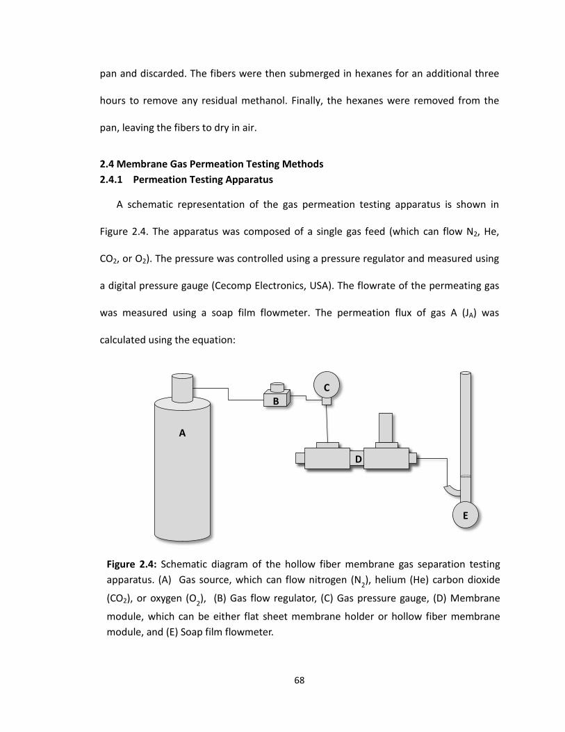
pan and discarded. The fibers were then submerged in hexanes for an additional three
hours to remove any residual methanol. Finally, the hexanes were removed from the
pan, leaving the fibers to dry in air.
2.4 Membrane Gas Permeation Testing Methods 2.4.1 Permeation Testing Apparatus
A schematic representation of the gas permeation testing apparatus is shown in
Figure 2.4. The apparatus was composed of a single gas feed (which can flow N2, He,
CO2, or O2). The pressure was controlled using a pressure regulator and measured using
a digital pressure gauge (Cecomp Electronics, USA). The flowrate of the permeating gas
was measured using a soap film flowmeter. The permeation flux of gas A (JA) was
calculated using the equation:
A
B C
D
E
Figure 2.4: Schematic diagram of the hollow fiber membrane gas separation testing apparatus. (A) Gas source, which can flow nitrogen (N2), helium (He) carbon dioxide
(CO2), or oxygen (O2), (B) Gas flow regulator, (C) Gas pressure gauge, (D) Membrane
module, which can be either flat sheet membrane holder or hollow fiber membrane module, and (E) Soap film flowmeter.
68

𝐽𝐽𝐴𝐴 = 𝑄𝑄𝐴𝐴𝐴𝐴
Where QA is the volumetric flowrate of gas A, measured with the soap film flowmeter,
and A is the total surface area of the circular flat sheet membrane or the hollow fiber
membrane bundle that is exposed to the gas. The permeance of gas A in the membrane
(PA/l) was then calculated using the following equation:
𝑃𝑃𝐴𝐴𝑙𝑙
= 𝐽𝐽𝐴𝐴∆𝑃𝑃
where PA is the permeability coefficient of gas A in the polymer, l is the thickness of the
dense separating layer of the membrane, and ΔP is the pressure difference across the
membrane in cmHg. The permeance is expressed in gas permeance units (GPU), where
1 𝐺𝐺𝑃𝑃𝐺𝐺 = 1𝑥𝑥10−6𝑐𝑐𝑃𝑃3(𝑆𝑆𝑀𝑀𝑃𝑃)𝑐𝑐𝑃𝑃2 𝑠𝑠 𝑐𝑐𝑃𝑃𝑐𝑐𝑐𝑐
The ideal selectivity between gas A and gas B is then simply defined as the ratio of the
pure gas permeance of gas A to the permeance of gas B (αA/B), as shown in the following
equation:
𝛼𝛼𝐴𝐴/𝐵𝐵 = (𝑃𝑃𝐴𝐴/𝑙𝑙)(𝑃𝑃𝐵𝐵/𝑙𝑙)
2.4.2 Flat Sheet Membrane Testing Procedure
The testing procedure for flat sheet membranes was relatively straightforward.
After the flat sheet was cast and subsequently subjected to solvent exchange and
drying, the membrane was cut into circular coupons of 1 inch diameter using a hole
[2.3]
[2.4]
[2.5]
69

punch. The circular membrane coupon was then loaded into a Millipore Microsyringe
Stainless Steel Filter Holder (Cat# xx3002514). A schematic diagram of the filter holder is
shown in Figure 2.5. The cell was assembled with the outlet of the filter holder on the
bottom, the NPT inlet to the filter holder on the top, and a flat Teflon O-ring, stainless
steel screen, membrane and rounded Teflon O-ring on the inside.
After the membrane cell had been assembled, it was placed into the gas
separation testing apparatus. Single gases were passed individually into the dead end
cell at a gauge pressure of 29 psi and the system was held at this pressure for 2 hours in
order to allow the flux to reach steady state. For a solution diffusion membrane, gas
transport across the membrane occurs in three steps. First, the gas dissolves into the
outer surface of the dense separating layer of the membrane, with its solubility
coefficient reflecting on how readily it interacts with the polymer. Next, the gas diffuses
A C D E FB
Figure 2.5: Schematic diagram of Millipore Microsyringe Stainless Steel Filter Holder (Cat# xx3002514) that was used for flat sheet membrane testing. (A) Outlet of the filter holder, (B) Flat Teflon O-ring, (C) Stainless steel screen, (D) Flat sheet asymmetric membrane sample, (E) Rounded Teflon O-ring, (F) Top of filter holder with NPT inlet.
70

across the dense separating layer of the membrane, driven by a concentration gradient.
The diffusion coefficient of the gas in the membrane is affected by multiple properties
of the material, including the fractional free volume and crystallinity of the polymer, as
well as the interaction between the polymer chains and the gas molecules. Lastly, the
gas desorbs from the dense separating layer and flows freely through the porous
support layer and out of the membrane holder, where the flowrate was measured by
the soap film flowmeter. The volumetric flux, permeance, and ideal selectivity of the
various gas pairs were then calculated using the equations presented in the previous
section.
2.4.3 PDMS Caulking
In order to ensure that the polymeric membranes were defect free and showed
solution diffusion (rather than Knudsen diffusion) separation characteristics, pinhole
defects in the flat sheet membranes need to be repaired. It is very common in the
membrane literature to repair these defects by “caulking” them with a high
permeability/low selectivity polymer, such as polydimethylsiloxane (PDMS)[14-16]. In
this work, the PDMS used was Sylgard-184, which was produced by Dow Corning and
purchased from Galco Industrial Electronics.
The procedure for caulking the flat sheet and hollow fiber membranes was as
follows. First, the curing agent was added to the Sylgard-184 silicone elastomer in a
ratio of 1:10, per the manufacturer’s recommendation. Hexane was then added to the
PDMS mixture in order to dilute the solution to 3 wt.% PDMS and stirred using a
magnetic stirrer. After the solution became completely homogeneous, the beaker was
71

covered with aluminum foil and the temperature of the solution was raised to 75°C in
order to increase branching and chain extension of the polymer solution. After the
solution had been held at 75 °C for 1 hour, a flat sheet membrane disc was immersed in
the PDMS solution. For hollow fiber membranes, the solution was poured into a PVC
tube with one end plugged, which contained the bundle of hollow fiber membranes, as
shown in Figure 2.6. The membrane (or HFM bundle) was allowed to soak for 30
minutes at 75 °C, and was then removed from the solution and placed in a vacuum oven
at 75 °C for 2 hours to complete PDMS curing.
Figure 2.6: Schematic diagram of HFM PDMS caulking soak (left) and photograph of HFM PDMS caulking soak (right).
72
2.4.4 Hollow Fiber Membrane Testing
2.4.4.1 Hollow Fiber Membrane Module Construction
A schematic configuration of a hollow fiber membrane test module is shown in
Figure 2.7a. As shown in the figure, the module is composed of an outer shell of PVC,
with a hollow fiber bundle potted into each end with epoxy, and one end of the epoxy
cut to expose the hollow core of the fibers. The outer shell consists of two tee fittings,
with one connected to the gas inlet and the other connected to a pressure safety valve.
Poly(vinylchloride) (PVC) was the chosen material for the shell of the module.
PVC pipe was cut into three 4 cm sections and glued into 0.5” tee fittings using PVC
cement. A completed module shell is shown in Figure 2.7b. Hollow fibers were then tied
together into a bundle using PTFE tape and paraffin wax was used to plug the ends of
the fibers to prevent epoxy from entering the hollow bore during potting. A HFM bundle
is shown in Figure 2.7c. The HFM bundle was then threaded through the module shell
and Tygon tubing was fed up the bottom of the module and out through the bottom tee
fitting. The thumb of a small, nitrile glove was used to cover the bottom of the module,
as shown in Figure 2.7d. The epoxy mixture, consisting of a 10:1 ratio of resin to
hardener, was then thoroughly mixed and pumped into the bottom of the module shell
through the tubing with a syringe. The membrane module was then placed in
convection oven at 50 °C for 2 hours to allow the epoxy to cure. After the epoxy was
fully cured, the module was turned over and excess fiber was cut from the top of the
module. The previous procedure was then repeated on the other side of the module.
73

Once the epoxy on both sides of the module was cured, one end of the HFM
module was cut off with a saw, leaving the hollow core of the fibers open and
embedded in an epoxy matrix. The cut end of the membrane module was immediately
placed in a DI water sonication bath and allowed to sonicate for 45 minutes to remove
any particulate epoxy that may be blocking the exit of the hollow fibers. A razor blade
was then used to cut open any fibers that remain blocked after sonication. An end-on
view of the potted, open hollow fibers is shown in Figure 2.7e. Since it was not possible
to ensure that all fibers were unblocked, the total number of unblocked fibers was
recorded. Vacuum grease was then applied to the PVC on the open end of the module
and the brass outlet fitting was fixed in place with electrical tape. The final HFM gas
separation testing module is shown in Figure 2.7f.
74

D E
F
Gas Inlet
Permeate Outlet
HFM Bundle
Safety Valve A
CB
Figure 2.7: Hollow fiber membrane module (A) Schematic diagram of HFM module, (B) Empty module shell, (C) HFM bundle, (D) Module prepared for epoxy injection, (E) End view of potted, open fibers, (F) Completed module.
75

2.4.4.2 Hollow Fiber Membrane Module Testing
After construction of the HFM module, the permeance testing procedure for
HFM membranes was very similar to that for the flat sheet membranes. The selected
gas (N2, He, CO2, or O2) was passed into the module in order to pressurize it to 29 psi.
The membrane module was then held at this pressure for two hours in order to allow
the flux to reach steady state. After this two hour conditioning period, the flowrate of
the permeate stream was measured using the soap film flowmeter and recorded. The
permeance of the membrane was then calculated accordingly.
2.5 Characterization Methods 2.5.1 Parallel Plate Rheometry
Polymer dope viscosity at various compositions, shear rates, and temperatures
was determined using a TA instruments AR G2 parallel plate rheometer. All
measurements were conducted using a 40 mm plate-plate geometry and a Peltier plate
temperature controller. A 500 µm gap spacing was employed, with paraffin oil
introduced at the edge to prevent solvent evaporation. Prior to measurement, each
sample was conditioned by bringing the temperature to 25°C. Sample viscosity was then
measured using steady state flow, with shear rates ranging from 0.01 – 10 s-1. After
completion of steady state flow measurements, the sample was conditioned at 25°C and
1 s-1 for 30 s. Oscillatory measurements were then conducted with an angular frequency
range of 0.1 – 500 rad/s.
76

2.5.2 Scanning Electron Microscopy (SEM)
Qualitative observations of the morphology and surface topography of films and
fibers were made using a Hitachi S-4800 scanning electron microscope. Membrane
samples were first submerged in liquid nitrogen and then fractured using tweezers. All
fracture surfaces were sputter coated with gold prior to imaging in the SEM to create a
conductive surface and prevent sample surface charging. The SEM was primarily
operated with an accelerating voltage (Vacc) of 15 kV and an emission current (Ie) of 10
µA.
2.5.3 Porometer
Liquid-liquid porometry is a characterization method that is designed to analyze
the pore structure of membranes and other materials of low porosity, such as ceramics
and textiles. It offers the ability to measure the pore diameter, pore size distribution and
liquid flowrate through porous low permeability materials. In this technique, two
immiscible liquids with differing surface tensions are employed. The liquid with the
lower surface tension (A) is used to fill the pores of the sample. The liquid with the
higher surface tension (B) is then added to the top of the sample and pressurized in
order to displace liquid A and generate flow through the pores. Additionally, the
flowrate of liquid B is measured without the pre-wetting of the sample by liquid A. The
permeability of the membrane is calculated using the measured flowrates, while the
pore diameter is calculated from the measured surface tension of the two liquids, using
the equation:
𝐷𝐷 = 4𝛾𝛾𝑐𝑐𝑃𝑃𝑠𝑠𝛾𝛾/𝛥𝛥𝑃𝑃 [2.6]
77

where D is the pore diameter, γ is the interfacial surface tension of the two liquids, θ is
the contact angle of liquid A on the surface of the pore, and ΔP is the differential
pressure applied to the sample by liquid B.
The pore size distribution of selected polymeric and mixed matrix membranes
was characterized using a Porous Materials, Inc. liquid-liquid porometer. In this
instrument, the liquid A (with lower surface tension) was Silwick liquid and liquid B
(with higher surface tension) was isopropyl alcohol (IPA). Since the two liquids both
have low surface tension, the contact angles are taken to be zero. Therefore, the pore
diameter calculation is simplified to
𝐷𝐷 = 4𝛾𝛾/𝛥𝛥𝑃𝑃
The operating pressure range of the porometer used was 1 to 500 psi and it had
a detectable pore size range of 0.001 – 0.5 µm. The membranes that were analyzed
were all circular flat sheet asymmetric membranes with a diameter of 2.54 cm.
[2.7]
78

2.6 References
1. Baker, R.W., Beckman, I. N., Cussler, E. L., Doshi, K, Henis, J. M. S., Koros, W. J.,Nakagawa, T., Paul, D. R., Petropoulos, J. H., Pinnau, I., Pixton, M. R., Plate, N, Prasad, R.,Shaner, R. L., Wijmans, J. G., Yampolskii, Y. P., Polymeric Gas Separation Membranes.1994: CRC Press Inc.
2. Hinds, B.J., Chopra, N., Rantell, T., Andrews, R., Gavalas, V., Bachas, L. G., Alignedmultiwalled carbon nanotube membranes. Science, 2004. 303(5654): p. 62-65.
3. Majumder, M., Chopra, N., Hinds, B. J., Effect of tip functionalization on transportthrough vertically oriented carbon nanotube membranes. Journal of the AmericanChemical Society, 2005. 127(25): p. 9062-9070.
4. Majumder, M., Chopra, N., Hinds, B. J., Mass transport through carbon nanotube membranes in three different regimes: ionic diffusion and gas and liquid flow. ACS Nano, 2011. 5(5): p. 3867-3877.
5. Ismail, A.F., Rahim N.H., Mustafa, A, Matsuura, T, Ng, B.C., Abdullah, S., Hashemifard, S.A., Gas separation performance of polyethersulfone/multi-walled carbon nanotubes mixed matrix membranes. Separation and Purification Reviews, 2011. 80: p. 20-31.
6. Aroon, M.A., Ismail, A. F., Matsuura, T., Montazer-Rahmati, M. M., Performance studiesof mixed matrix membranes for gas separation: A review. Separation and PurificationTechnology, 2010. 75(3): p. 229-242.
7. Goh, P.S., Ismail, A. F., Sanip, S. M., Ng, B. C., Aziz, M., Recent advances of inorganicfillers in mixed matrix membrane for gas separation. Separation and PurificationTechnology, 2011. 81(3): p. 243-264.
8. Goh, P.S., Ng, B. C., Ismail, A. F., Sanip, S. M., Aziz, M., Kassim, M. A., Effect of dispersed multi-walled carbon nanotubes on mixed matrix membrane for O2/N2 separation. Separation Science and Technology, 2011. 46(8): p. 1250-1261.
9. Ismail, A.F., Goh, P. S., Sanip, S. M., Aziz, M., Transport and separation properties ofcarbon nanotube-mixed matrix membrane. Separation and Purification Technology,2009. 70(1): p. 12-26.
10. Moore, T.T., Koros, W. J., Gas sorption in polymers, molecular sieves, and mixed matrixmembranes. Journal of Applied Polymer Science, 2007. 104(6): p. 4053-4059.
11. S. Zeinali, M.A., Improving O2/N2 Selective filtration using carbon nanotube-modified mixed-matrix membranes. Chemical Engineering and Technology, 2015. 38(11): p. 2079-2086.
12. Andrews, R., Jacques, D., Qian, D. L., Rantell, T., Multiwall carbon nanotubes: Synthesisand application. Accounts of Chemical Research, 2002. 35(12): p. 1008-1017.
13. Loeb, S., Sourirajan, S., Sea water demineralization bymeans of a semipermeablemembrane. Advances in Chemistry, 1962. 38: p. 117-132.
14. Jomekian, A., Mansoori, S. A. A., Monirimanesh, N., Shafiee, A., Gas transport behaviorof DMDCS modified MCM-48/polysulfone mixed matrix membrane coated by PDMS.Korean Journal of Chemical Engineering, 2011. 28(10): p. 2069-2075.
15. Li, P., H.Z. Chen, and T.S. Chung, The effects of substrate characteristics and pre-wettingagents on PAN-PDMS composite hollow fiber membranes for CO2/N2 and O2/N2
separation. Journal of Membrane Science, 2013. 434: p. 18-25.16. Singh, A., Freeman, B. D., Pinnau, I., Pure and mixed gas acetone/nitrogen permeation
properties of polydimethylsiloxane PDMS. Journal of Polymer Science Part B-PolymerPhysics, 1998. 36(2): p. 289-301.
79

Chapter 3: Development of PES-MWCNT Flat Sheet Membranes
3.1 Introduction 3.1.1 Asymmetric Flat Sheet Membranes
When first invented by Loeb and Sourirajan in the 1960s [1], asymmetric flat
sheet membranes composed of cellulose acetate were an enormous technological
breakthrough for membrane-based separations. They allowed for membranes to be
fabricated in such a way as to increase the flux across the membrane to a practical level
while maintaining structural integrity. This was achieved by producing a single
membrane that was composed of a thin (0.1 – 1 µm) dense layer on top of a porous
support of the same material. In this type of asymmetric structure, the dense top layer
acts as a thin membrane through which separation occurs, while the porous sub-
structure provides mechanical support to withstand the applied pressure differential.
In order to fabricate an asymmetric flat sheet gas separation membrane, a thin
film of polymer solution (dope) is cast onto an appropriate substrate. This cast thin film
is then immersed in a coagulation bath of nonsolvent or a solvent/nonsolvent mixture
[2-6], which causes the dope to separate into two phases, one polymer-rich and the
other polymer-lean. The polymer-rich phase solidifies during this process and forms the
membrane, including the dense separating layer and the walls of the porous support.
The polymer-lean phase forms the open pores in the membrane sub-structure. The final
morphology and performance of the membrane are heavily influenced by the
composition of both the dope and the coagulation medium [7]. For example, a dope
without a sufficient weight fraction of polymer will form nodules of polymer-rich phase
80

suspended within a continuous matrix of polymer-lean phase, which is not conducive to
membrane formation. Only if the polymer composition of the dope is sufficiently high
will an asymmetric membrane form, leading to a continuous matrix of polymer-rich
phase with droplets of polymer-lean phase forming the porous support structure. The
composition of the coagulation medium is also vital to the structure and performance of
the membrane by influencing the rate and type of demixing that occurs during
coagulation. When the coagulation bath is composed of pure nonsolvent (or a high
concentration of nonsolvent), instantaneous demixing occurs, which results in the
formation of a dense separating layer at the dope-coagulant interface and the
emergence of a porous sub-structure. Instantaneous demixing is often accompanied by
the formation of finger-like macrovoids just below the dense layer which are created by
the intrusion of non-solvent into the membrane during solidification. If the membrane is
immersed in a coagulation bath that is solvent-rich, delayed demixing occurs, resulting
in the suppression of macrovoids, but also a membrane that consists only of an open,
homogeneous porous structure with no dense separating layer. The balance necessary
to minimize the formation of macrovoids, which act as mechanical weak points in the
membrane structure, while maintaining the integrity of the dense separating layer, is
critical to the formation of a viable flat sheet membrane for gas separation.
The next major advance in the preparation of asymmetric gas separation
membranes came in the late 1960s, when Loeb and Sourirajan developed a solvent
exchange and drying procedure that prevented the collapse of the membrane pore
structure upon drying [4]. This development expanded the applications for these
81
membranes from wet processes, such as reverse osmosis (RO) and ultrafiltration (UF), to
dry processes, such as gas separation. In the solvent exchange procedure, the as-cast
membrane is allowed to soak in water to extract residual solvent from within the pore
structure. The membrane is then immersed in a lower boiling point water-miscible
solvent (i.e. methanol) in order to extract the water within the membrane, and finally is
immersed in a third low boiling point solvent that is miscible with the second solvent but
is immiscible with water (i.e. hexane or pentane). The final solvent is then allowed to
evaporate, resulting in a dried membrane without compromising the integrity of the
pore structure.
For most industrial applications, flat sheet membranes are cast as long
continuous sheets that are sealed and spiral wound around a central perforated tube.
The membrane module is then pressurized with the gas mixture to be separated, which
forces the gas that is more permeable in the membrane material to permeate across the
membrane and exit out through the perforated tube in a more concentrated stream.
The retentate gas then exits the module and is generally diverted back into the original
feed stream to improve separation efficiency.
Flat sheet asymmetric membranes were an enormous improvement in the field
of membrane-based gas separation technology. Prior to their invention, membranes
that were thin enough (< 1 µm) to provide commercially-viable fluxes were not durable
enough to remain intact in a high pressure (> 200 psi) environment. Asymmetric
82

membranes were able to deliver the high flux associated with ultrathin membranes as
well as the structural durability of a much thicker membrane.
3.1.2 Material Systems of Interest 3.1.2.1 Membrane Polymer
Polyethersulfone (PES) has been one of the most commonly used polymers in
the field of membrane separation for several decades. It is frequently used as both the
separating element itself as well as the porous substrate upon which thin film composite
membranes are cast. PES is a relatively high Tg glassy thermoplastic, with a rigid repeat
unit structure which imparts good thermal, chemical, and mechanical properties. It also
readily forms asymmetric membranes via phase inversion in aqueous media due to its
strong hydrophobicity. Additionally, it is commercially available and is fairly low cost
compared to other polymeric membrane materials. Therefore, it has been the focus of
much membrane-related research in the area of liquid phase separation (reverse
osmosis, micro/ultra/nanofiltration, etc.) as well as gas separation. Polysulfone (PSf) is a
similar polymer to PES, but with an additional bisphenol moiety in the polymer repeat
unit. It is more commonly used in industrial gas separations, such as the Air Products
PRISM membrane system, because it shows comparable ideal selectivities and higher
permeability than PES.
Research conducted on the gas transport properties of PES asymmetric
membranes typically involves the characterization of membranes coated with a very
thin layer of polydimethylsiloxane (PDMS), which is required to repair or “caulk” the
microscopic pinhole defects that form in the dense selective layer during phase
83
inversion [8-10]. As discussed in Section 1.1.2.3, PDMS is used because its high
permeability and low selectivity minimally impact membrane performance by shifting
the dominant gas diffusion mechanism from non-selective Knudsen diffusion through
the pinholes to solution diffusion across the membrane polymer [11, 12]. Accordingly,
PES-PDMS asymmetric membranes have been reported to provide O2/N2 pure-gas ideal
selectivities in the range of 5.6 [13] - 6.0 [9]. The O2 permeance values for these types of
membranes are reported to be in the range of 1.0 GPU [10] to 30 GPU [9].
3.1.2.2 Mixed Matrix Membranes
Due to their superior performance over wholly-polymeric membranes, much
research in recent decades has been focused on the development of mixed matrix
membranes [14-19]. Mixed matrix membranes are typically comprised of a porous
inorganic filler material dispersed within a polymer matrix. Mixed matrix membranes
(MMMs) often exhibit improved separation performance over traditional polymeric
membranes through the addition of a molecular sieving component to the diffusion
mechanism. As illustrated schematically in Figure 3.1, MMMs improve the size
separation by forcing large molecules to take a more tortuous path through the
membrane dense separating layer, while allowing small molecules to flow through the
pores of the inorganic filler. Early versions of these membranes involved zeolites as the
inorganic filler material, due to their low cost, commercial availability and narrow pore
size distributions [20-23]. The major drawback of using zeolites is that, owing to their
inorganic nature, they tend to exhibit poor adhesion to the polymer matrix, which
results in a decrease in membrane selectivity by creating non-selective channels at the
84
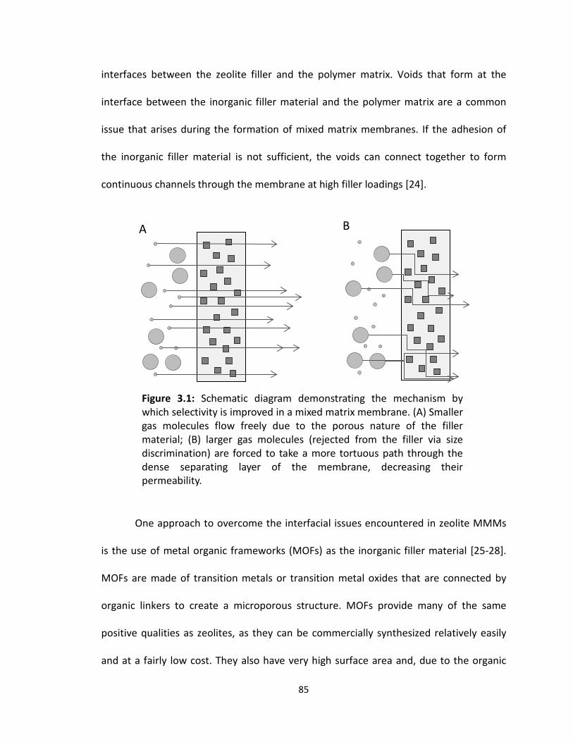
interfaces between the zeolite filler and the polymer matrix. Voids that form at the
interface between the inorganic filler material and the polymer matrix are a common
issue that arises during the formation of mixed matrix membranes. If the adhesion of
the inorganic filler material is not sufficient, the voids can connect together to form
continuous channels through the membrane at high filler loadings [24].
One approach to overcome the interfacial issues encountered in zeolite MMMs
is the use of metal organic frameworks (MOFs) as the inorganic filler material [25-28].
MOFs are made of transition metals or transition metal oxides that are connected by
organic linkers to create a microporous structure. MOFs provide many of the same
positive qualities as zeolites, as they can be commercially synthesized relatively easily
and at a fairly low cost. They also have very high surface area and, due to the organic
A B
Figure 3.1: Schematic diagram demonstrating the mechanism by which selectivity is improved in a mixed matrix membrane. (A) Smaller gas molecules flow freely due to the porous nature of the filler material; (B) larger gas molecules (rejected from the filler via size discrimination) are forced to take a more tortuous path through the dense separating layer of the membrane, decreasing their permeability.
85

linkers, can be produced with tunable pore sizes and small pore size distributions. MOFs
offer improvement over zeolites as the filler material in MMMs because the organic
linker molecules can be selected to ensure good adhesion with the polymer matrix.
Since their first discovery and major reports in the early 1990s by Ijima et al.,
carbon nanotubes (CNTs) have been extensively studied for their mechanical, electrical
and thermal properties, and more recently have begun to be incorporated into
membrane materials[29]. For example, aligned carbon nanotubes have been used for
the fabrication of highly-controlled nanoporous water filtration membranes [30-33].
Additionally, CNTs have been incorporated as the inorganic filler material in gas
separation MMMs; multiwall carbon nanotubes (MWCNTs) have been thought to act as
molecular sieves due to their intrinsic interlayer spacing [34]. Since carbon nanotubes
have a strong tendency to agglomerate, much of the research surrounding their use in
MMMs centers on CNTs that have been oxidized and/or functionalized in order to
improve their adhesion to the polymer matrix [16, 19, 34-39]. In these studies, the
oxidized and functionalized CNTs typically show better dispersion within the polymer
matrix (usually PES or PSf) and a large improvement in both O2/N2 and CO2/CH4
selectivity as compared with the inclusion of pristine CNTs. The researchers attribute the
selectivity difference to the poor dispersion of the pristine CNTs, resulting in
agglomeration of the tubes. This agglomeration of CNTs leads to an increase in non-
selective interface defects in the separating layer of the membrane.
86
Previous work by Weisenberger et al. has demonstrated the ability to achieve a
uniform dispersion of MWCNTs in polyacrylonitrile (PAN) solution spinning dopes for the
production of PAN-based carbon fiber precursor [40]. The dispersion was achieved
without oxidation or functionalization of the MWCNTs, using a combination of wand
ultrasonication and subsequent centrifugation to sediment agglomerated MWCNTs.
Only the homogeneous MWCNT dispersion, decanted from the supernatant after
centrifuging, was used. This result is important to the work reported herein because it
suggested that a viable CNT-based polymeric mixed matrix membrane could be
produced without the need for surface modification of the MWCNTs.
3.2 Results and Discussion 3.2.1 Rheology of Membrane Casting Dopes 3.2.1.1 Polyethersulfone Viscosity Measurements
One of the most important processing factors for both the casting of flat sheet
membranes and the spinning of hollow fiber membranes is the viscosity of the polymer
dope. In the sections that follow, the morphologies of flat sheet phase inversion-derived
membranes, based on PES and PSf, are examined as a function of dope composition and
coagulation conditions. A key consideration in establishing the dope composition (i.e.
dissolved polymer content) is the corresponding solution viscosity of the dope. Prior
work has suggested a target viscosity in the range of 100 to 200 Pa.s for dry-jet spinning
of solid fiber under comparable operating conditions [41]. Since the flat sheet
membrane experiments were conducted with an objective to extend the results to
hollow fiber spinning, this target range was the basis by which initial dope compositions
were established for studies of flat sheet membrane casting.
87

A TA instruments AR G2 parallel plate rheometer was used to determine the
steady-shear viscosity of polymer dope solutions of varying composition with both N,N-
dimethylacetimide (DMAc) and N-methylpyrrolidone (NMP) as solvents. Plots of the
viscosity (at 25°C and 1 s-1) versus polymer content for PES (MW = 55,000) in DMAc and
NMP, as well as PSf (MW = 60,000) in NMP, are shown in Figure 3.2. For PES, the
solution viscosity ranged from 1 to 500 Pa.s over the range of 20 to 40 wt.% polymer
content, with similar results obtained for both solvents; PSf showed comparable
viscosities for solutions prepared in NMP. In each case, an exponential relationship was
obtained for viscosity as a function of concentration, leading to a linear result when
plotted on a semi-log basis.
1
10
100
1000
15 20 25 30 35 40 45
Visc
osity
(Pa.
s )
Polymer Concentration (wt.%)
PES in DMAc
PES in NMP
PSf in NMP
Figure 3.2: Relationship between the polymer dope viscosity at 25 oC and 1 s-1 and polymer concentration for PES in NMP and DMAc, as well as PSf in NMP.
88
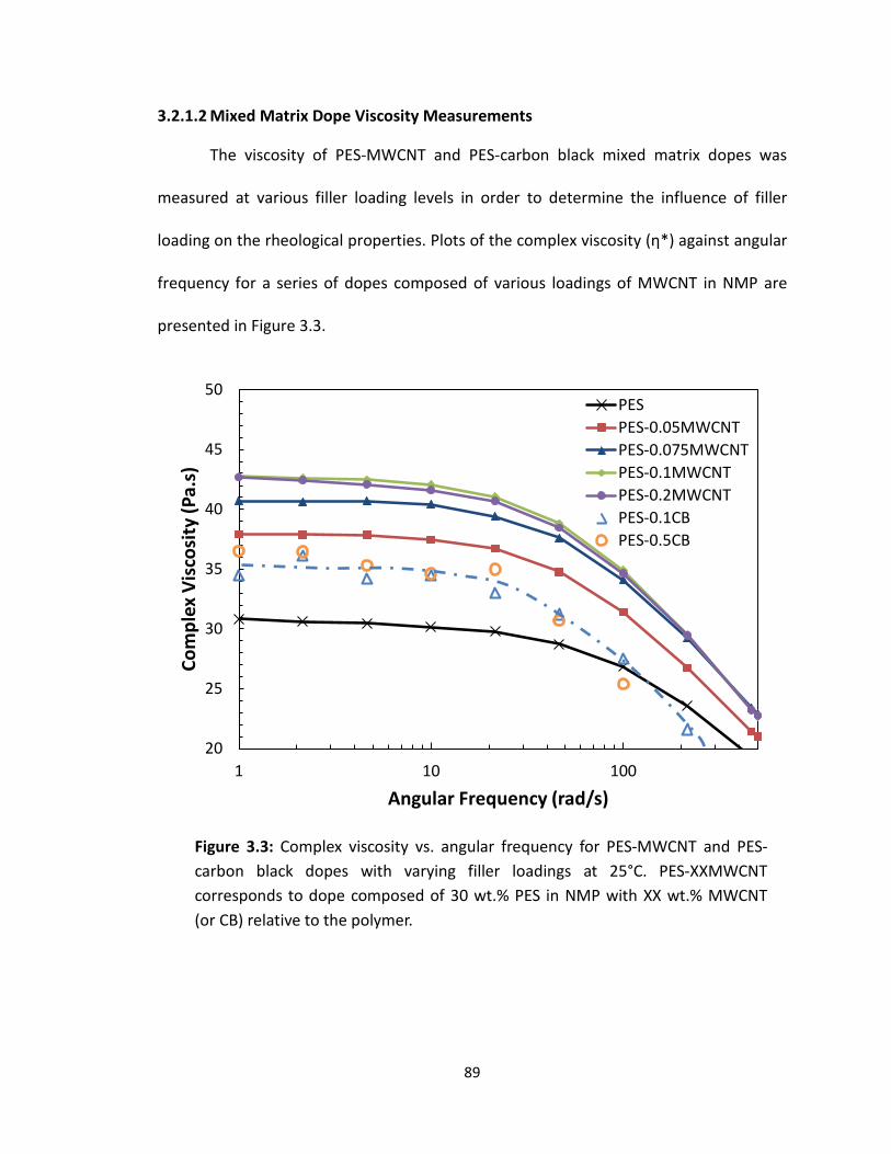
3.2.1.2 Mixed Matrix Dope Viscosity Measurements
The viscosity of PES-MWCNT and PES-carbon black mixed matrix dopes was
measured at various filler loading levels in order to determine the influence of filler
loading on the rheological properties. Plots of the complex viscosity (ƞ*) against angular
frequency for a series of dopes composed of various loadings of MWCNT in NMP are
presented in Figure 3.3.
20
25
30
35
40
45
50
1 10 100
Com
plex
Vis
cosi
ty (P
a.s)
Angular Frequency (rad/s)
PESPES-0.05MWCNTPES-0.075MWCNTPES-0.1MWCNTPES-0.2MWCNTPES-0.1CBPES-0.5CB
Figure 3.3: Complex viscosity vs. angular frequency for PES-MWCNT and PES-carbon black dopes with varying filler loadings at 25°C. PES-XXMWCNT corresponds to dope composed of 30 wt.% PES in NMP with XX wt.% MWCNT (or CB) relative to the polymer.
89

Increasing MWCNT concentration increased the complex viscosity of the dope until the
loading reached 0.1 wt.% MWCNT relative to the polymer. At 0.2 wt.%, the complex
viscosity did not appear to increase any further. As will be discussed later in Section
3.2.4.1, 0.1 wt.% MWCNT was coincident with a large increase in the ideal selectivity of
membranes that were cast using this dope. In addition, the figure demonstrates that the
carbon black filler resulted in a significantly smaller increase in the complex viscosity,
compared to the MWCNT filler, even up to 0.5 wt.% carbon black. One of the primary
differences between the two filler materials is the large aspect ratio of the MWCNTs
compared to the (nominally-spherical) carbon black particles. After 20 minutes of similar
sonication, the average length of MWCNTs in dispersion was elsewhere reported to be
approximately 5 – 10 µm [42]. Since the MWCNTs are approximately 40 nm in outer
diameter, this corresponds to an aspect ratio of 125 to 250. The large aspect ratio
inherent to the nanotubes has been shown to foster entanglement with the polymer
chains at relatively low MWCNT loadings, resulting in an increase in dope viscosity [43].
3.2.2 Flat Sheet Membrane Morphology 3.2.2.1 Effect of Coagulation Bath Composition on Membrane Morphology
Polyethersulfone (PES) asymmetric membranes were phase-inverted in
coagulation baths of pure deionized water, and 50, 60, and 70 wt.% DMAc in deionized
water. The initial target viscosity value of 200 Pa.s corresponded to a polymer content
of approximately 38.5 wt.% PES in solution, which was selected at the outset for the flat
sheet membrane casting studies. These studies were conducted in order to examine the
phase inversion characteristics of the resulting flat sheet membranes, and to establish
90
the corresponding parameters for flat sheet membrane casting and hollow fiber
membrane spinning in future experiments. SEM micrographs of each cryogenically
fractured membrane surface are shown in Figure 3.4; the membrane surface exposed to
the coagulation bath is indicated by an arrow in each case. For the membrane prepared
via coagulation in deionized water, a dense top layer was observed, with finger-like
macrovoids extending into the porous sub-structure to a depth equivalent to about one-
half of the membrane thickness. It was clear from the micrographs that an increase in
the solvent content of the coagulation bath resulted in a decrease in the relative
penetration depth (i.e. length) of macrovoids extending from the film surface that was
exposed to the coagulant. The membrane cross sections that are presented in Figures
3.4c-d showed a morphological transition between a coagulation composition of 60
wt.% DMAc, where relatively short finger-like macrovoids were observed, and 70 wt.%
DMAc, where the thin films were virtually macrovoid free. The overall trend reflected
the instantaneous demixing of the polymer solution that occurs when exposed to pure
non-solvent, which creates a dense outer skin and finger-like macrovoids just below the
surface. An increase in solvent content within the coagulation bath led increasingly to
delayed demixing, resulting in a more uniform sponge-like substructure and the
appearance of distinct pores on the surface of the membrane. These large surface pores
were distinct from pinhole defects that can be repaired through PDMS caulking (as
described in Section 1.1.2.3), as the former are formed when the porous substructure
breaks through the top surface during phase inversion.
91
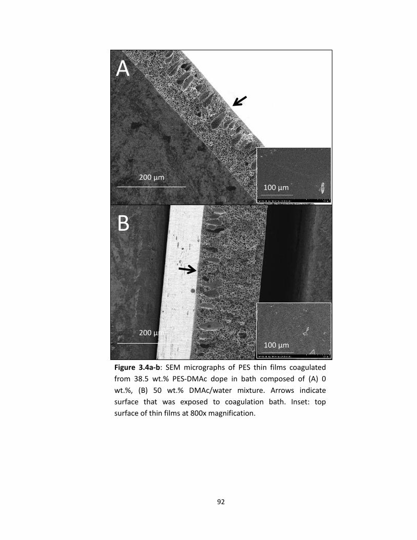
Figure 3.4a-b: SEM micrographs of PES thin films coagulated from 38.5 wt.% PES-DMAc dope in bath composed of (A) 0 wt.%, (B) 50 wt.% DMAc/water mixture. Arrows indicate surface that was exposed to coagulation bath. Inset: top surface of thin films at 800x magnification.
A
200 µm
B
200 µm
92
100 µm
100 µm

D
200 µm
C
200 µm
Figure 3.4c-d: SEM micrographs of PES thin films coagulated from 38.5 wt.% PES-DMAc dope in bath composed of (C) 60 wt.%, (D) 70 wt.% DMAc/water mixture. Arrow indicates exposure face. Inset: top surface of thin films at 800x magnification.
93
100 µm
100 µm

For gas separations, it is vitally important to have a thin, dense, defect-free separating
layer on the outer surface of the membrane to maintain selectivity. For this reason,
deionized water was used as the phase-inversion medium for all asymmetric flat sheet
membranes that were prepared for the gas separation experiments reported in this
work.
Similar experiments were conducted using dopes composed of 35 wt.%
polysulfone (PSf) in N-methylpyrrolidone (NMP). Consistent with the PES flat-sheet
membranes, low concentrations of NMP in the coagulation bath led to PSf membrane
structures that exhibited a dense separating layer on top of a porous sub-structure with
large finger-like macrovoids propagating downward through the cross-section of the
membrane; see Figure 3.5. As the coagulation bath became more solvent-rich, the
relative penetration depth of the finger-like voids decreased. In contrast to the PES
casting system, when the coagulation bath composition was 70 wt.% solvent, a dense
separating layer and sparse macrovoids were still evident.
94

Figure 3.5a-b: SEM micrographs of PSf thin films coagulated from 35 wt.% PES-NMP dope in bath composed of (A) 0 wt.%, (B) 50 wt.% NMP/water mixture. Arrow indicates exposure face.
B
100 µm
A
100 µm
95

C
100 µm
D
100 µm
Figure 3.5c-d: SEM micrographs of PSf thin films coagulated from 35 wt.% PSf-NMP dope in bath composed of (A) 60 wt.%, (B) 70 wt.% NMP/water mixture. Arrow indicates exposure face.
96

3.2.2.2 Effect of Polymer Concentration on Membrane Morphology
The relationship between polymer concentration in the dope solution and
asymmetric membrane morphology was examined by casting flat sheet membranes
from dopes composed of varying concentrations of polymer. Dope preparation and
casting were carried out using the methods detailed in section 2.3.1. The films were cast
using solutions composed of 15, 20, 25, 30, and 35 wt.% PES in DMAc. For PSf, flat sheet
membranes were cast from dopes of 25, 27.5, 30, 32.5, and 35 wt.% PSf in NMP.
Representative SEM micrographs for the PES flat sheet samples are shown in
Figure 3.6. These samples were cast in a coagulation medium of deionized water. Cross
sections of films cast from dopes with low concentrations of PES (< 25 wt.%) showed
morphologies with large voids and comparatively little of the desired porous
substructure. The PES dope composed of 30 wt.% PES in DMAc was found to produce an
acceptable morphology that was virtually the same as that produced from 38.5 wt.%
PES in DMAc. Additionally, as shown in Section 3.2.1.1, 30 wt.% PES in DMAc had a
significantly lower viscosity than that of 38.5 wt.% PES, which allowed a much lower
pressure drop during filtering (in later hollow fiber work). Since its coagulation resulted
in comparable thin film membrane morphologies without the practical processing
limitations of the higher viscosity formulation, 30 wt.% PES dope was chosen for all
subsequent flat sheet PES membrane experiments.
97

Figure 3.6a-b: SEM micrographs of PES thin films cast using dope composed of (A) 15 wt.% and (B) 20 wt.% PES in DMAc with deionized water as the coagulation medium. Arrow indicates exposure face.
100 µm
A
100 µm
B
98

C
100 µm
100 µm
D
Figure 3.6c-d: SEM micrographs of PES thin films cast using dope composed of (C) 25 wt.% and (D) 30 wt.% PES in DMAc with deionized water as the coagulation medium. Arrow indicates exposure face.
99

A similar result was obtained for PSf flat sheet specimens, which is shown in
Figure 3.7. When concentrations of PSf below 30 wt.% were used to cast the films, very
little of the desired sponge-like morphology was formed in the porous support layer,
which was instead composed mostly of long, finger-like macrovoids. As the PSf
concentration of the dope was increased to above 30 wt.%, a more consistent porous
support region emerged, with a dense separating layer evident near the coagulation
bath interface. Based on these results (as well as the viscosity data for the PSf dopes),
35 wt.% PSf in NMP was chosen as the preferred dope for flat sheet casting of
polysulfone membranes. It should be noted that, when all other casting parameters
were held equal, PSf flat sheet membranes showed both higher occurrence and longer
macrovoids than the corresponding PES membranes.
100 µm
E
Figure 3.6e: SEM micrographs of PES thin films cast using dope composed of (E) 35 wt.% PES in DMAc with deionized water as the coagulation medium. Arrow indicates exposure face.
100
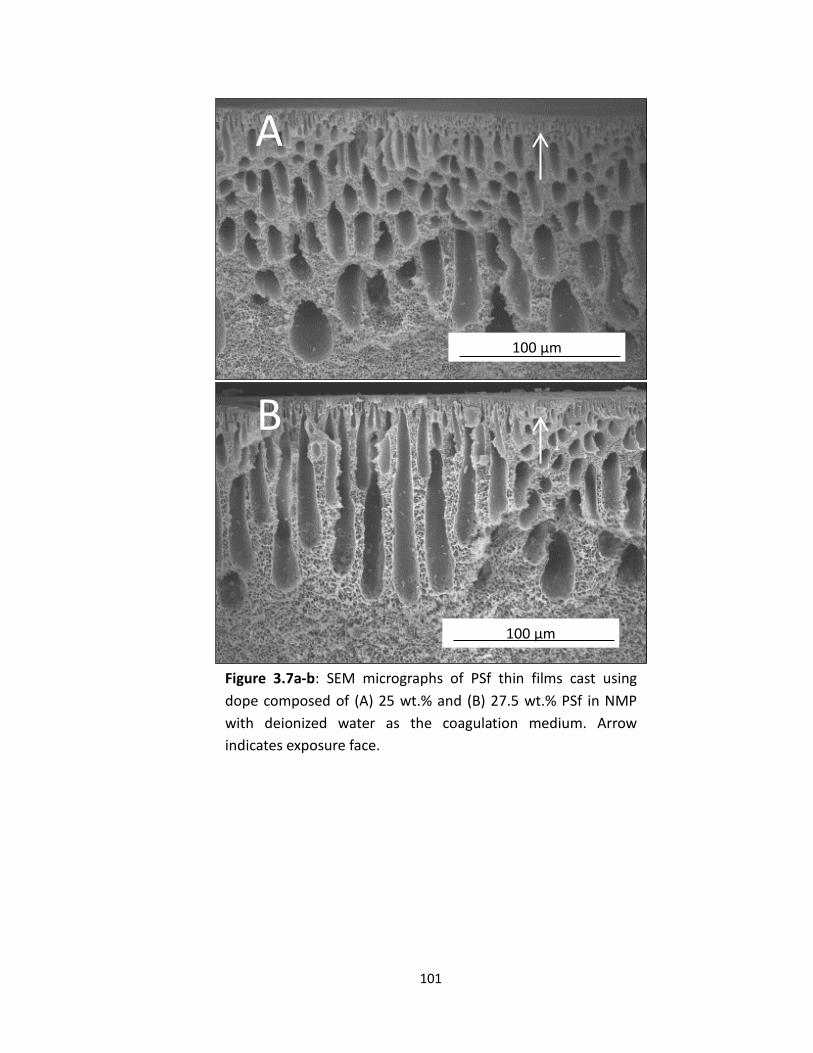
Figure 3.7a-b: SEM micrographs of PSf thin films cast using dope composed of (A) 25 wt.% and (B) 27.5 wt.% PSf in NMP with deionized water as the coagulation medium. Arrow indicates exposure face.
A
100 µm
B
100 µm
101

D
100 µm
C
100 µm
Figure 3.7c-d: SEM micrographs of PSf thin films cast using dope composed of (C) 30 wt.% and (D) 32.5 wt.% PSf in NMP with deionized water as the coagulation medium. Arrow indicates exposure face.
102

3.2.2.3 Effect of Solvent on Membrane Morphology
After performing several flat sheet membrane experiments using DMAc as the
PES solvent, it was determined that N-Methylpyrrolidone (NMP) could easily replace
DMAc as a less hazardous alternative without significantly altering membrane
preparation. In order to assess the impact of the solvent change on membrane
morphology, a series of PES membranes were cast from NMP dope solution with varying
coagulant composition. A casting composition of 30 wt.% PES in NMP was selected for
the dope, consistent with the discussion presented above; membranes were quenched
in 0, 50, 60, and 70 wt.% NMP in water. SEM micrographs of these membranes are
shown in Figure 3.8.
E
100 µm
Figure 3.7e: SEM micrographs of PSf thin films cast using dope composed of 35 wt.% PSf in NMP with deionized water as the coagulation medium. Arrow indicates exposure face.
103

Figure 3.8a-b: SEM micrographs of PES thin films coagulated from 30 wt.% PES-NMP dope in bath composed of (A) 0 wt.%, (B) 50 wt.% NMP/water mixture. Arrow indicates exposure face.
100 µm
A
100 µm
B
104

100 µm
D100 µm
C
Figure 3.8c-d: SEM micrographs of PES thin films coagulated from 30 wt.% PES-NMP dope in bath composed of (C) 60 wt.%, (D) 70 wt.% NMP/water mixture. Arrow indicates exposure face.
105
When the coagulation medium was composed of pure deionized water, a dense
separating layer was formed at the dope-coagulant interface, with finger-like
macrovoids that extended approximately halfway across the membrane cross section.
The remaining cross section was composed of sponge-like substructure, with a porous
topology observed at the membrane-substrate interface. As the concentration of NMP
in the coagulation bath was increased, the relative penetration depth of the voids
decreased, and they were virtually eliminated when the coagulation bath concentration
reached 70 wt.% NMP. A direct comparison of the thin film cross sections obtained
using the two different solvents (and corresponding coagulation mixtures) is shown in
Figure 3.9. Based on these micrographs, it was determined that thin films that were cast
from these two solvents produced sufficiently similar morphologies. Therefore, it was
deemed appropriate to use less hazardous NMP as the solvent for all subsequent flat
sheet and hollow fiber membrane experiments.
106

A
200 µm
100 µm
B
Figure 3.9a-b: Comparison of SEM micrographs of 30 wt.% PES thin films cast from (A) DMAc and (B) NMP using deionized water as the coagulation medium. Arrow indicates surface that was exposed to coagulation bath.
107

100 µm
D
C
200 µm
Figure 3.9c-d: Comparison of SEM micrographs of 30 wt.% PES thin films cast from (C) DMAc and (D) NMP using 70 wt.% solvent in water as the coagulation medium. Arrow indicates surface that was exposed to coagulation bath.
108

3.2.2.4 Effect of MWCNT Loading on PES Membrane Morphology
Experiments were conducted to examine the effects of incorporating multiple
carbon-based filler materials into the polymeric membrane matrix. Previous studies by
Ismail [34] and Zeinali [35] indicated that modest enhancements in O2/N2 selectivity
could be achieved upon the incorporation of low levels of well-dispersed carbon
nanotubes within flat-sheet PES membranes. In the current work, the impact of
MWCNT incorporation on the morphology and transport properties of PES flat sheet
membranes was assessed both for as-cast membranes and membranes subject to post-
processing via coating with PDMS. In addition to evaluating the efficacy of nanotube
inclusion for improving the performance of the flat sheet membranes, the extension of
this approach to hollow fiber membranes is reported here for the first time, as discussed
in Chapter 4.
Flat sheet membranes were cast from dopes of 30 wt.% PES in NMP, with a
nominal dispersion of 0.05 to 0.5 wt.% MWCNT, relative to the polymer, using the
MWCNT dope preparation and flat sheet membrane casting procedures described in
Sections 2.3.1.1.2 and 2.3.1.2, respectively. Transmitted light optical microscope images
of a series of PES-MWCNT casting dope samples are shown in Figure 3.10. An interesting
contrast was observed in the MWCNT dispersion as the filler loading was increased. Up
until a moderate loading (i.e. 0.1 wt.%), the MWCNTs appeared to be well dispersed
within the polymer dope, while at 0.5 wt.% loading, the MWCNTs showed evidence of
segregation into MWCNT-rich and MWCNT-lean regions. The MWCNT-rich regions
appeared to be comprised of loosely-associated, segregated regions of MWCNTs. This
109

segregation was distinct from the formation of tightly-associated macro-scale MWCNT
agglomerates, which would generally be removed during the centrifugation process.
Membranes were cast from dopes containing 0.1 wt.% MWCNT relative to the
polymer with coagulation baths of deionized water and 70 wt.% NMP/water. Figure 3.11
shows a comparison of the neat PES membrane and the PES-MWCNT flat sheet
membrane (0.1 wt% MWCNT) that were phase-inverted in pure water. SEM
micrographs of both samples showed a dense separating layer with large, finger-like
macrovoids extending approximately halfway across the thickness of the membrane.
Below the macrovoids, each membrane showed the desired sponge-like morphology for
the porous support structure. The addition of the well-dispersed MWCNTs appeared to
have a moderate impact on the characteristics of the porous substructure, which
included longer, more slender finger-like macrovoids when quenched in deionized
water. This change in the morphology is most likely due to an increase in the solution
Figure 3.10: Optical microscope images of 30 wt.% PES in NMP dopes with (A) 0.05, (B) 0.1, and (C) 0.5 wt.% MWCNT dispersions (Arrow indicates MWCNT agglomerate that was not removed during centrifugation). Nominal magnification is 50x.
110

viscosity slowing down the phase inversion dynamics, leading to longer macrovoid
formation.
Figure 3.11: Comparison of SEM micrographs of (A) unfilled PES flat sheet membrane and (B) PES flat sheet membrane loaded with 0.1 wt.% MWCNT. Dopes contain 30 wt.% PES in NMP and deionized water was used as the coagulation medium. Arrow indicates exposure face.
100 µm
A
100 µm
B
111

200 µm
A
B
200 µm
Figure 3.12: Comparison of SEM micrographs of (A) unfilled 30 wt.% PES-NMP flat sheet membrane and (B) 30 wt.% PES-NMP flat sheet membrane loaded with 0.1 wt.% MWCNT. 70 wt.% NMP/water was used as the coagulation medium. Arrow indicates exposure face. Inset: Membrane surface that was exposed to coagulation bath.
100 µm
100 µm
112

A small difference in morphology was also observed in the membranes that were
cast in a coagulation bath of 70 wt.% NMP/water, as shown in Figure 3.12. For the
unfilled PES membrane, this coagulation bath concentration resulted in a morphology
that was entirely composed of sponge-like porous support structure, whereas in the
PES-MWCNT membrane, small tear-drop shaped macrovoids persisted just below the
exposed top layer. When looking at the top surface of the membrane, however, large
pores, stemming from the break-through of the porous substructure, were still evident
in the SEM micrographs, consistent with a phase inversion process dominated by
delayed demixing (also observed in Figure 3.4d). Detection of the MWCNTs in an
asymmetric membrane cross section using SEM was difficult at such low loadings, but
they were observed in SEM images of PES dense films (Figure 3.13). Figure 3.13 also
shows the macroscopic color change that provides additional evidence that the
MWCNTs were fully incorporated in the final membrane coupons.
PES PES-0.1MWCNT 2.0 µm
Figure 3.13: (Left) SEM image of PES-0.1MWCNT dense film cross-section. Arrows indicate MWCNTs. (Right) photograph of PES and PES-0.1MWCNT membrane coupons, showing macroscopic color change that accompanies MWCNT dispersion.
113

3.2.3 Gas Permeance and Selectivity for Flat Sheet Membranes 3.2.3.1 Permeance and Selectivity of PES and PSf Membranes
The gas permeance and selectivity of the flat sheet membrane coupons were
measured using the procedure described in Section 2.4.2. The casting parameters for
the flat sheet membranes that were tested for gas permeation properties were chosen
based on the experimental results that were presented in Section 3.2.2. These
parameters, which are summarized in Table 3.1, were specifically selected with
consideration of future objectives related to the preparation of analogous hollow fiber
membranes.
Table 3.1: Membrane casting parameters and test conditions for single gas permeance studies. Process Parameters: Value:
Polymer PES, PSf
Solvent NMP
Filler Materials MWCNT, Carbon Black
Polymer Concentration (wt.%) 30 (PES), 35 (PSf)
Coagulation Bath Deionized water
Casting Blade Height 250 µm
PDMS Caulk (where applicable) 3 wt.% PDMS in hexanes
Membrane Coupon Diameter (cm) 2.54
Pressure Differential (ΔP, psi) 29
Membrane Conditioning Period (hr) 2.0
114
The permeance of N2 and O2, as well as the O2/N2 pure-gas selectivity, are
summarized for unfilled PES and PSf membranes in Table 3.2. While there were a total
of three gas pairs that were examined in this work, the primary focus of these
experiments was O2/N2 selectivity, due to the fact that air separation is the most
industrially relevant process for the application of PES and PSf membranes in this
context. As reported in the table, both PES and PSf as-cast membranes showed O2/N2
selectivities on the order of 0.90, which is characteristic of Knudsen diffusion for this gas
pair[4]. Since Knudsen selectivity was observed in these membranes, it was concluded
that the dense separating layer contained microscopic pinhole defects, and further post-
treatments would be required to achieve the characteristic (i.e., dense film) selectivity
inherent to the membrane polymers [13]. In fact, the presence of pinhole surface
defects in polymer membranes, typically too small to clearly image with SEM, is a very
common issue for the preparation of gas separation membranes, and is most often
addressed by PDMS caulking. As discussed in Section 1.1.2.3, PDMS caulking is a
method used to mitigate the negative effects of pinhole defects. By coating the
membrane with the high permeability, low selectivity PDMS polymer, the properties of
the bulk membrane are minimally affected, but the diffusion mechanism in the pinhole
defects is changed from Knudsen diffusion to solution diffusion through PDMS, which
largely eliminates the high gas flux and minimal selectivity inherent to the pinhole
defects.
115

Table 3.2 reports the N2 and O2 permeance as well as the O2/N2 selectivity of the
unfilled PES and PSf membranes that were caulked with PDMS. The PDMS caulking was
performed by soaking the membrane coupon for 30 minutes in a solution of 3 wt.%
PDMS in hexanes. It is relevant to note at this point that relatively little effort was
directed towards minimizing or otherwise optimizing the thickness of the PDMS coating
that was applied to the membranes. Both membranes showed a large decrease in the
permeance of O2, along with a proportionally larger decrease in N2 permeance with
PDMS coating. The difference in the magnitude of the permeance reduction for the two
gases resulted in an increase in the O2/N2 pure-gas selectivity for both the PES and PSf
membranes. The O2/N2 ideal selectivity of PES increased from 0.89 to 5.5, and the O2/N2
ideal selectivity of PSf increased from 0.94 to 5.1. The previously reported literature
values for the dense film O2/N2 ideal selectivity for PES and PSf are 5.6 and 5.2,
respectively [13]. The observed increase in the selectivity of the membranes from
Knudsen levels to the reference values reported for PES and PSf is consistent with the
presence of pinhole defects in the membranes that were successfully caulked via the
application of PDMS to the membrane surface.
Table 3.2: Permeance and ideal selectivity of N2 and O2 for unfilled PES and PSf membranes in the as-cast and PDMS-caulked states.
Material P/l (N2) (GPU) P/l (O2) (GPU) α(O2/N2)
PES-Flat Sheet 23.4 ± 0.5 20.8 ± 0.7 0.89 ± 0.05
PSf-Flat Sheet 31.9 ± 0.01 29.9 ± 0.5 0.94 ± 0.04
PES-PDMS-Flat Sheet 0.07 ± 0.01 0.41 ± 0.03 5.51 ± 0.03
PSf-PDMS-Flat Sheet 0.16 ± 0.02 0.82 ± 0.07 5.12 ± 0.03
116

3.2.3.2 Effect of MWCNT Loading on PES Membrane Permselectivity
In order to investigate the effect of MWCNT content on the permeance and
selectivity of PES-MWCNT mixed matrix membranes, membranes were fabricated with
nominal MWCNT loadings ranging from 0.05 to 0.5 wt.% relative to the polymer, with
NMP as the solvent and deionized water as the coagulation medium (no solvent added)
– see Table 3.1. The actual (retained) filler concentration was determined using the
method described in Section 2.3.1.1.2.
Figure 3.14a shows plots of N2, O2, He and CO2 permeance as related to MWCNT
loading (expressed as wt.% relative to polymer) for as-cast membrane samples. At very
low loading, nominally 0.05 wt.% MWCNT, the presence of the nanotubes appeared to
have very little effect on the permeance of the membrane and Knudsen selectivity was
observed. However, at a nominal loading of 0.1 wt.% MWCNT, O2, He, and CO2
permeance decreased by an order of magnitude, while the permeance of N2 decreased
by two orders of magnitude. This was a striking and unexpected observation, which
resulted in an increase in ideal selectivity for all gas pairs relative to N2, with O2/N2
peaking at an ideal selectivity very close to the inherent selectivity of unfilled PES, as
shown in Figure 3.14b. This result suggested a change in the diffusion mechanism from
Knudsen diffusion to solution diffusion transport. It is particularly noteworthy that this
effect was observed prior to the use of any post-treatment, such as PDMS caulking.
117

0.01
0.10
1.00
10.00
100.00
0.0 0.1 0.2 0.3 0.4 0.5
Perm
eanc
e (G
PU)
MWCNT Loading (Wt.%)
He
CO2
O2
N2
He
CO2
O2
N2
Figure 3.14a: Average He, CO2, O2, and N2 permeance (GPU) of PES-MWCNT
mixed matrix membranes, plotted against MWCNT loading. Each data point was measured in triplicate and error bars represent standard deviation of the three measurements.
118

0
5
10
15
20
25
0.0 0.1 0.2 0.3 0.4 0.5
Idea
l Sel
ectiv
ity (A
vg)
MWCNT Loading (Wt.%)
He/N2
CO2/N2
O2/N2
He/N2
CO2/N2
O2/N2
Figure 3.14b: Average He/N2, CO2/N2, and O2/N2 ideal selectivity of PES-MWCNT
mixed matrix membranes, plotted against MWCNT loading. Each data point was measured in triplicate and error bars represent standard deviation of the three measurements.
119

As the weight fraction of MWCNTs in the membranes was increased beyond 0.1
wt.%, the permeance of the membrane was maintained at relatively low levels until the
loading reached a nominal level of 0.3 wt.%. The observed lower plateau in permeance
was accompanied by a decrease in selectivity, which still remained well above the levels
encountered with Knudsen diffusion. When the nominal weight fraction of MWCNTs
reached 0.5 wt.% relative to the polymer, the permeance increased and the selectivity
of the membrane was reduced back to Knudsen levels (re: Figure 3.14).
The large decrease in the observed permeance of the as-cast membranes and
their enhanced pure gas selectivity with low levels of MWCNT incorporation was
consistent with the outcomes achieved via PDMS caulking of the unfilled membranes,
suggesting that the MWCNTs were in some way acting to suppress the formation of
pinhole defects and thereby shifting the transport from Knudsen diffusion to a solution-
diffusion mechanism. In order to further explore this phenomenon, the porosity of the
membranes was analyzed using a Porous Materials Inc. automated liquid-liquid
porometer. The results of this test showed that for neat PES membranes with no PDMS
caulking, surface pores in the range of 1.1 to 2.7 nm were detected, providing
confirmation that the observed high gas permeance as well as the Knudsen selectivity
was due to the presence of pinhole defects in the dense separating layer of the
membrane. For the PES-0.1 wt.% MWCNT membrane, the analyzer detected no surface
porosity. Since this latter result was achieved without using any PDMS caulking, it
indicated that the MWCNTs were somehow suppressing either the formation of pinhole
defects or were fully obstructing flow in the pinhole defects, resulting in a large
120
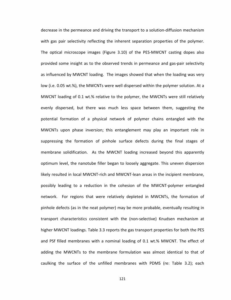
decrease in the permeance and driving the transport to a solution-diffusion mechanism
with gas pair selectivity reflecting the inherent separation properties of the polymer.
The optical microscope images (Figure 3.10) of the PES-MWCNT casting dopes also
provided some insight as to the observed trends in permeance and gas-pair selectivity
as influenced by MWCNT loading. The images showed that when the loading was very
low (i.e. 0.05 wt.%), the MWCNTs were well dispersed within the polymer solution. At a
MWCNT loading of 0.1 wt.% relative to the polymer, the MWCNTs were still relatively
evenly dispersed, but there was much less space between them, suggesting the
potential formation of a physical network of polymer chains entangled with the
MWCNTs upon phase inversion; this entanglement may play an important role in
suppressing the formation of pinhole surface defects during the final stages of
membrane solidification. As the MWCNT loading increased beyond this apparently
optimum level, the nanotube filler began to loosely aggregate. This uneven dispersion
likely resulted in local MWCNT-rich and MWCNT-lean areas in the incipient membrane,
possibly leading to a reduction in the cohesion of the MWCNT-polymer entangled
network. For regions that were relatively depleted in MWCNTs, the formation of
pinhole defects (as in the neat polymer) may be more probable, eventually resulting in
transport characteristics consistent with the (non-selective) Knudsen mechanism at
higher MWCNT loadings. Table 3.3 reports the gas transport properties for both the PES
and PSf filled membranes with a nominal loading of 0.1 wt.% MWCNT. The effect of
adding the MWCNTs to the membrane formulation was almost identical to that of
caulking the surface of the unfilled membranes with PDMS (re: Table 3.2); each
121

membrane pair (caulked PES vs. filled PES; caulked PSf vs. filled PSf) showed remarkable
similarity in terms of both overall gas permeance and resulting O2/N2 selectivity. These
results strongly support the hypothesis that the inclusion of relatively low levels of
MWCNTs prevents the formation of pinhole surface defects during the casting of these
membranes. In addition, the data presented in the tables indicate that this approach
can be generalized to different membrane polymers, since both PES and PSf showed
very similar results. As with the unfilled membranes, PSf showed higher permeance in
both the caulked state as well as the mixed matrix state, but also displayed lower O2/N2
selectivity in both, as compared to PES. This was consistent with the literature, as it is
well documented that PSf tends to have a higher permeance and lower ideal selectivity
for most gas pairs due to the higher fractional free volume inherent to the polymer[13].
In sum, this is the first report clearly indicating the role of MWCNTs in suppressing
pinhole defect formation during the phase inversion casting of asymmetric gas
separation membranes.
122
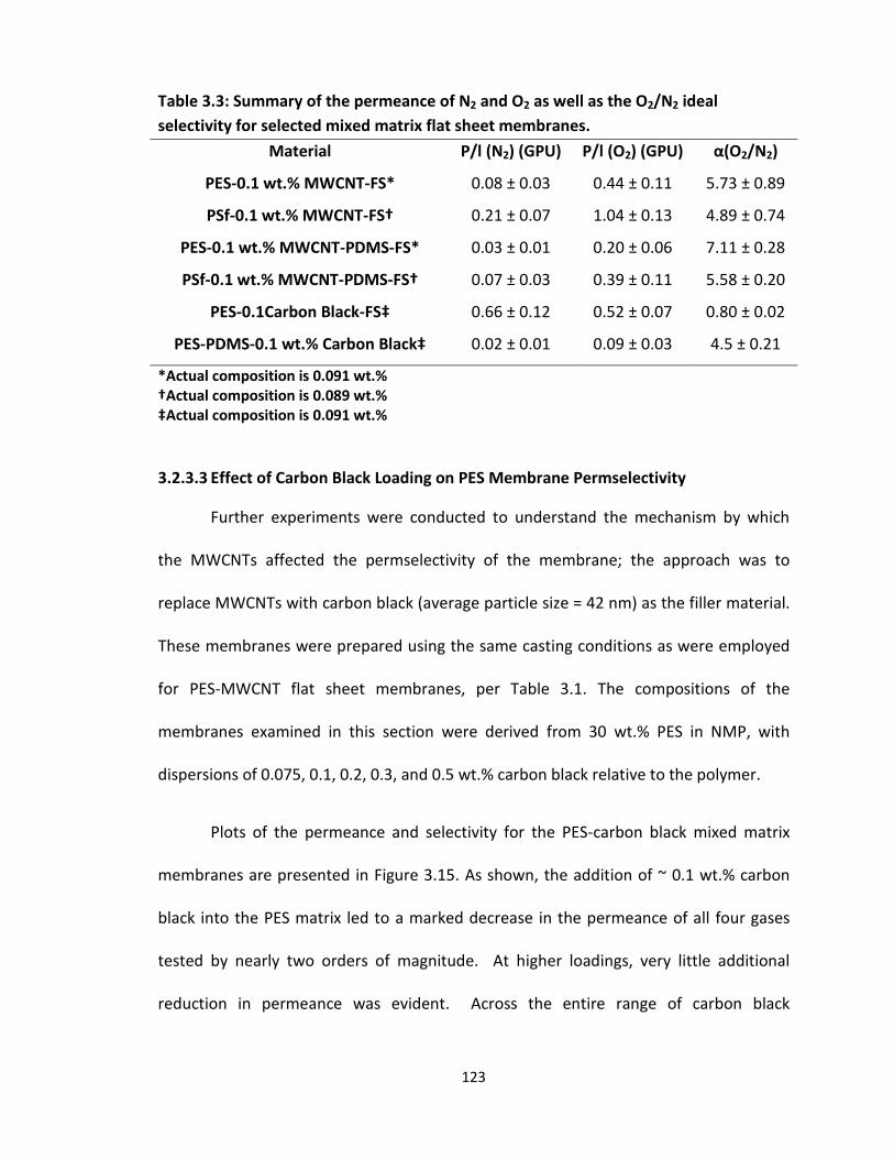
3.2.3.3 Effect of Carbon Black Loading on PES Membrane Permselectivity
Further experiments were conducted to understand the mechanism by which
the MWCNTs affected the permselectivity of the membrane; the approach was to
replace MWCNTs with carbon black (average particle size = 42 nm) as the filler material.
These membranes were prepared using the same casting conditions as were employed
for PES-MWCNT flat sheet membranes, per Table 3.1. The compositions of the
membranes examined in this section were derived from 30 wt.% PES in NMP, with
dispersions of 0.075, 0.1, 0.2, 0.3, and 0.5 wt.% carbon black relative to the polymer.
Plots of the permeance and selectivity for the PES-carbon black mixed matrix
membranes are presented in Figure 3.15. As shown, the addition of ~ 0.1 wt.% carbon
black into the PES matrix led to a marked decrease in the permeance of all four gases
tested by nearly two orders of magnitude. At higher loadings, very little additional
reduction in permeance was evident. Across the entire range of carbon black
Table 3.3: Summary of the permeance of N2 and O2 as well as the O2/N2 ideal selectivity for selected mixed matrix flat sheet membranes.
Material P/l (N2) (GPU) P/l (O2) (GPU) α(O2/N2)
PES-0.1 wt.% MWCNT-FS* 0.08 ± 0.03 0.44 ± 0.11 5.73 ± 0.89
PSf-0.1 wt.% MWCNT-FS† 0.21 ± 0.07 1.04 ± 0.13 4.89 ± 0.74
PES-0.1 wt.% MWCNT-PDMS-FS* 0.03 ± 0.01 0.20 ± 0.06 7.11 ± 0.28
PSf-0.1 wt.% MWCNT-PDMS-FS† 0.07 ± 0.03 0.39 ± 0.11 5.58 ± 0.20
PES-0.1Carbon Black-FS‡ 0.66 ± 0.12 0.52 ± 0.07 0.80 ± 0.02
PES-PDMS-0.1 wt.% Carbon Black‡ 0.02 ± 0.01 0.09 ± 0.03 4.5 ± 0.21
*Actual composition is 0.091 wt.%†Actual composition is 0.089 wt.% ‡Actual composition is 0.091 wt.%
123
compositions, the pure gas selectivity was characteristic of Knudsen diffusion,
presumably through pinhole surface defects.
It is proposed that the presence of MWCNTs prevented the creation of pinhole
defects during polymer phase inversion by entangling with the polymer chains and
forming a physical network that suppressed the formation of openings on the
membrane surface during polymer solidification from solution. This hypothesis was
further supported by the carbon black results, where this effect was largely absent.
Owing to their lower aspect ratio, the carbon black particles are less likely to effectively
entangle with the polymer chains during phase inversion, thus limiting the ability of the
filler to physically inhibit the opening of pinhole gaps on the membrane surface as the
polymer solidifies. Rather, the data suggest that the large decrease in the gas
permeance of these membranes is due to the carbon black particles physically
obstructing at least some fraction of the pinhole defects. Since the particles do not fully
block all of the pinholes, Knudsen diffusion is still the predominant diffusion mechanism
in the membrane, such that no improvement in ideal selectivity was observed as
compared to an unfilled membrane.
124

0.01
0.10
1.00
10.00
100.00
0.0 0.1 0.2 0.3 0.4 0.5
Perm
eanc
e (G
PU)
Carbon Black Loading (Wt.%)
He
CO2
O2
N2
He
CO2
O2
N2
Figure 3.15a: Average He, CO2, O2, and N2 permeance (GPU) of PES-carbon black
mixed matrix membranes, plotted against carbon black loading. Each data point was measured in triplicate and error bars represent standard deviation of the three measurements.
125

0.0
5.0
10.0
15.0
20.0
25.0
0.00 0.10 0.20 0.30 0.40 0.50
Idea
l Sel
ectiv
ity
Carbon Black Loading (Wt.%)
He/N2
CO2/N2
O2/N2
He/N2
CO2/N2
O2/N2
Figure 3.15b: Average He/N2, CO2/N2, and O2/N2 ideal selectivity of PES-carbon
black mixed matrix membranes, plotted against carbon black loading. Each data point was measured in triplicate and error bars represent standard deviation of three points.
126

3.2.3.4 Effect of MWCNT Loading on PES-PDMS Membrane Permselectivity
In addition to observing the effects of adding MWCNT and carbon black filler
material to the as-cast PES membranes, the permeance and selectivity of the filled
membranes were measured after the application of PDMS. Figure 3.16a shows the
permeance of the four gases tested as they relate to MWCNT loading for membranes
that were subsequently subjected to PDMS caulking. For all membrane compositions,
the permeance and selectivity values were consistent with gas transport via solution-
diffusion, as discussed above, with the PDMS coating eliminating potential Knudsen
diffusion through pinhole surface defects. In addition, across the range of relatively low
filler loadings investigated, increasing MWCNT content had little influence on the
permeance of the caulked membranes. Plots of ideal selectivity vs. MWCNT loading for
the PDMS-coated PES membranes are shown in Figure 3.16b. PDMS caulking increased
the selectivity of the neat PES membrane from a level that was characteristic of Knudsen
diffusion to a level that was consistent with solution-diffusion transport. A local
maximum in ideal selectivity was evident at a nominal loading of 0.1 wt.% MWCNT, but
was much less pronounced as compared to the uncaulked membrane series. Across this
range of filler loading, it appeared that the primary benefit of PDMS coating was to
repair any residual pinholes that may have been present on the surface of the MWCNT-
filled membranes. The fact that there was a small further improvement in selectivity
with the application of the PDMS surface layer could reflect the influence of an
additional separation mechanism attributable to the presence of the MWCNTs, such as
molecular sieving. Previous work performed by Ismail et al. on PES-MWCNT membranes
127
with PDMS caulking showed an increase in O2/N2 ideal selectivity from 5.52 to 10.65 at a
loading of 0.5 wt.% when the nanotube dispersion was improved through chemical
functionalization of the nanotubes. In their work, molecular sieving through the MWCNT
interlayer spacing was cited as the primary mechanism for the observed improvement in
ideal selectivity [34].
Parallel experiments were conducted for PSf membranes loaded with 0.1 wt.%
MWCNT and subject to PDMS coating. The results for these membranes, as well as
comparable PES specimens, are summarized in Table 3.3. For both polymers, the coated
mixed-matrix membranes showed a slight decrease in permeance (owing to the added
transport resistance of the PDMS toplayer), as well as an increase in the ideal selectivity
of the membrane. As was the case in all of the previous experiments, PSf membranes
showed a higher permeance as well as a lower ideal O2/N2 selectivity as compared to
PES, owing to either the larger fractional free volume inherent to the PSf polymer or
possibly a thinner dense separating layer in these membranes.
128

0.01
0.10
1.00
10.00
100.00
0.0 0.1 0.2 0.3 0.4 0.5
Perm
eanc
e (G
PU)
MWCNT Loading (Wt.%)
He
CO2
O2
N2
He
CO2
O2
N2
Figure 3.16a: Average He, CO2, O2, and N2 permeance (GPU) of PDMS-caulked PES-
MWCNT mixed matrix membranes, plotted against MWCNT loading. Each data point was measured in triplicate and error bars represent standard deviation of the three measurements.
129

0
5
10
15
20
25
0.0 0.1 0.2 0.3 0.4 0.5
Idea
l Sel
ectiv
ity (A
vg)
MWCNT Loading (Wt.%)
He/N2
CO2/N2
O2/N2
He/N2
CO2/N2
O2/N2
Figure 3.16b: Average He/N2, CO2/N2, and O2/N2 ideal selectivity of PDMS-caulked
PES-MWCNT mixed matrix membranes, plotted against MWCNT loading. Each data point was measured in triplicate and error bars represent standard deviation of the three measurements.
130
3.2.3.5 Effect of Carbon Black Loading on PES-PDMS Membrane Permselectivity
The effect of PDMS caulking on PES membranes loaded with carbon black
particles was also examined. Plots of the permeance and selectivity as a function of
carbon black loading are shown in Figure 3.17. As can be seen in Figure 3.17a, when
PDMS caulking was applied after membrane casting, only a modest additional reduction
in permeance was observed with increasing carbon black loading. This is consistent with
the carbon black particles acting to substantially obstruct the surface defects; the
subsequent PDMS coating, while producing only a small additional reduction in
permeance with the sealing of surface gaps, effectively shifts the permeation
mechanism to solution-diffusion transport for all membrane compositions. Examination
of Figure 3.17b shows selectivity values largely independent of carbon black loading,
and consistent with as-cast, caulked PES membranes; see also Table 3.3.
131

0.01
0.10
1.00
10.00
100.00
0.0 0.1 0.2 0.3 0.4 0.5
Perm
eanc
e (G
PU)
Carbon Black Loading (Wt.%)
He
CO2
O2
N2
He
CO2
O2
N2
Figure 3.17a: Average He, CO2, O2, and N2 permeance (GPU) of PDMS-caulked PES-
carbon black mixed matrix membranes, plotted against carbon black loading. Each data point was measured in triplicate and error bars represent standard deviation of three points.
132

0
5
10
15
20
25
0.00 0.10 0.20 0.30 0.40 0.50
Idea
l Sel
ectiv
ity
Carbon Black Loading (Wt.%)
He/N2
CO2/N2
O2/N2
He/N2
CO2/N2
O2/N2
Figure 3.17b: Average He/N2, CO2/N2, and O2/N2 ideal selectivity of PDMS-
caulked PES-carbon black mixed matrix membranes, plotted against carbon black loading. Each data point was measured in triplicate and error bars represent standard deviation of three points.
133
3.3 Conclusions
In this chapter, multiple aspects of the preparation of polyethersulfone (PES) flat
sheet phase inversion membranes were studied in order to establish appropriate
conditions for flat sheet casting and (later) hollow fiber spinning of PES and PSf
asymmetric membranes. Based on the solution viscosity and morphology of membranes
that were cast from various dope compositions, it was determined to employ a dope
solution of 30 wt.% PES in NMP for the preparation of gas separation membranes. This
provided a dope viscosity low enough to avoid unsustainably high filtering pressures
anticipated during hollow fiber spinning, while maintaining PES content sufficient to
produce a suitable membrane morphology when cast as an asymmetric thin film.
Experiments using various coagulation bath compositions were conducted to determine
the effect of coagulation conditions on membrane morphology, and to guide the
selection of the coagulation bath and bore fluid compositions for hollow fiber
membrane spinning. Based on the morphologies of the flat sheet membranes that were
produced, it was determined that the bore fluid should be composed of 70 wt.% NMP in
water for PES hollow fiber membrane spinning and 75 wt.% NMP in water for PSf hollow
fiber membrane spinning. When phase inversion was accomplished under these
coagulation conditions, the membranes showed no macrovoid formation, and both the
top and bottom surfaces of the membrane were porous, which is the ideal morphology
for the inner wall of a hollow fiber membrane.
Multiwall carbon nanotubes and carbon black particles were dispersed in the
polymer casting dopes in order to assess the influence of relatively low levels of these
134

fillers on the morphology and gas transport properties of the resulting asymmetric
mixed-matrix membranes. At loadings up to 0.5 wt.% filler, the presence of the filler had
minimal discernable impact on the membrane morphologies obtained under the various
membrane casting conditions. Consideration of the gas separation performance
indicated that the addition of pristine MWCNTs had a marked impact at a loading of
approximately 0.1 wt.% relative to the polymer. At this loading, the as-cast PES-MWCNT
mixed matrix membrane exhibited a large reduction in permeance and an increase in
selectivity to a level comparable to that of unfilled PES membranes coated with
polydimethylsiloxane (PDMS). The results the MWCNTs functioned to suppress the
formation of microscopic pinhole defects on the surface of the polymer membrane. This
is the first report clearly indicating the role of MWCNTs in eliminating pinhole defect
formation during the phase inversion casting of asymmetric gas separation membranes.
It was hypothesized that the observed improvement in the ideal selectivity of the mixed
matrix membranes was the result of polymer chains entangling with the high aspect
ratio MWCNTs during membrane formation, creating a physical network of polymer-
MWCNT interphase which prevented the emergence of pinhole defects. As the loading
of the MWCNTs was further increased, segregation of the tubes into MWCNT-rich and
MWCNT-lean regions correlated with a progressive decrease in membrane selectivity.
The MWCNT-lean regions were likely more susceptible to pinhole defect formation, as
observed for the neat membranes. This corresponded to a strong increase in the
permeance of the membranes and a return to selectivity levels consistent with Knudsen
diffusion when the MWCNT loading was approximately 0.5 wt.% relative to the polymer.
135
The observed suppression of pinhole defect formation with the introduction of very
low levels of MWCNTs in the membrane casting dope offers a range of potential
technological benefits, including the possible elimination of a separate PDMS coating
step as required to repair the membrane surface for acceptable gas separation
performance. This could be especially important in the context of industrial processing
requiring caulking of each gas separation module separately. In an effort to assess the
generality of this outcome, similar membranes were prepared with low levels of carbon
black particles as the filler. In the case of the carbon-black filled membranes, a decrease
in permeance was encountered that suggested the partial blocking of pinhole surface
defects with the presence of the particles, but the poor selectivity inherent to Knudsen
diffusion persisted at all loading levels. It was conclusively shown that that the
incorporation of MWCNTs suppressed the formation of pinhole defects and it was
further hypothesized that filler (i.e. nanotube) aspect ratio was a key factor in
establishing entanglement of the filler elements with the polymer chains during
membrane coagulation. This entanglement may reinforce the emerging membrane top
layer thereby suppressing pinhole formation.
136

3.4 References
1. Loeb, S., Sourirajan, S., Sea water demineralization bymeans of a semipermeablemembrane. Advances in Chemistry, 1962. 38: p. 117-132.
2. Kurdi, J., Tremblay, A. Y., Preparation of defect-free asymmetric membranes forgas separations. Journal of Applied Polymer Science, 1999. 73(8): p. 1471-1482.
3. Kulprathipanja, S., Neuzil, R.W., Norman, N. L., Separation of fluids by means ofmixed matrix membranes. 1989, Honeywell International Inc: USA, US5127925A.
4. Koros, W.J., Fleming, G. K., Membrane-based gas separation. Journal ofMembrane Science, 1993. 83(1): p. 1-80.
5. Khulbe, K.C., Feng, C., Matsuura, T., The Art of Surface Modification of SyntheticPolymeric Membranes. Journal of Applied Polymer Science, 2010. 115(2): p. 855-895.
6. Kesting, R.E., Synthetic Polymeric Membranes: A Structural Perspective. Seconded. Vol. 1. 1985: John Wiley & Sons, Inc. 348.
7. Peng, N., Widjojo, N., Sukitpaneenit, P., Teoh, M. M., Lipscomb, G. G., Chung, T.S., Lai, J. Y., Evolution of polymeric hollow fibers as sustainable technologies:Past, present, and future. Progress in Polymer Science, 2012. 37(10): p. 1401-1424.
8. Madaeni, S.S., Hoseini, S., Fabrication and characterization of PDMS coated PESmembranes for separation of ethylene from nitrogen. Journal of PolymerResearch, 2009. 16(5): p. 591-599.
9. Sadrzadeh, M., Amirilargani, M., Shahidi, K., Mohammadi, T., Gas permeationthrough a synthesized composite PDMS/PES membrane. Journal of MembraneScience, 2009. 342(1-2): p. 236-250.
10. Wang, D.L., Li, K., Teo, W. K., Gas permselection properties in silicone-coatedasymmetric polyethersulfone membranes. Journal of Applied Polymer Science,1997. 66(5): p. 837-846.
11. Merkel, T.C., Bondar, V. I., Nagai, K., Freeman, B. D., Pinnau, I., Gas sorption,diffusion, and permeation in poly(dimethylsiloxane). Journal of Polymer SciencePart B-Polymer Physics, 2000. 38(3): p. 415-434.
12. Henis, J.M.S., Tripodi, M. K., Composite hollow fiber membranes for gasseparation - the resistance model approach. Journal of Membrane Science, 1981.8(3): p. 233-246.
13. Baker, R.W., Beckman, I. N., Cussler, E. L., Doshi, K, Henis, J. M. S., Koros, W. J.,Nakagawa, T., Paul, D. R., Petropoulos, J. H., Pinnau, I., Pixton, M. R., Plate, N,Prasad, R., Shaner, R. L., Wijmans, J. G., Yampolskii, Y. P., Polymeric GasSeparation Membranes. 1994: CRC Press Inc.
14. Galizia, M., Chi, W. S., Smith, Z. P., Merkel, T. C., Baker, R. W., Freeman, B. D.,50th Anniversary Perspective: Polymers and Mixed Matrix Membranes for Gasand Vapor Separation: A Review and Prospective Opportunities. Macromolecules,2017. 50(20): p. 7809-7843.
137

15. Kemp, D.R., Paul, D. R., Gas sorption in polymer membranes containingadsorptive fillers. Journal of Polymer Science Part B-Polymer Physics, 1974. 12(3):p. 485-500.
16. Moore, T.T., Koros, W. J., Gas sorption in polymers, molecular sieves, and mixedmatrix membranes. Journal of Applied Polymer Science, 2007. 104(6): p. 4053-4059.
17. Mahajan, R., Koros, W. J., Mixed matrix membrane materials with glassypolymers. Part 2. Polymer Engineering and Science, 2002. 42(7): p. 1432-1441.
18. Chung, T.S., Jiang, L. Y., Li, Y., Kulprathipanja, S., Mixed matrix membranes(MMMs) comprising organic polymers with dispersed inorganic fillers for gasseparation. Progress in Polymer Science, 2007. 32(4): p. 483-507.
19. Goh, P.S., Ismail, A. F., Sanip, S. M., Ng, B. C., Aziz, M., Recent advances ofinorganic fillers in mixed matrix membrane for gas separation. Separation andPurification Technology, 2011. 81(3): p. 243-264.
20. Ahn, J., Chung, Wook-Jin, Pinnau, Ingo, Guiver, Michael D., Poly sulfone/silicananoparticle mixed-matrix membranes for gas separation. Journal of MembraneScience, 2008. 314(1-2): p. 123-133.
21. Husain, S. and W.J. Koros, Mixed matrix hollow fiber membranes made withmodified HSSZ-13 zeolite in polyetherimide polymer matrix for gas separation.Journal of Membrane Science, 2007. 288(1-2): p. 195-207.
22. Boroglu, M.S., Gurkaynak, Mehmet Ali, Fabrication and characterization of silicamodified polyimide-zeolite mixed matrix membranes for gas separationproperties. Polymer Bulletin, 2011. 66(4): p. 463-478.
23. Li, Y., Chung, T. S., Cao, C., Kulprathipanja, S., The effects of polymer chainrigidification, zeolite pore size and pore blockage on polyethersulfone (PES)-zeolite A mixed matrix membranes. Journal of Membrane Science, 2005. 260(1-2): p. 45-55.
24. Wang, M., Z. Wang, N. Li, J.Y. Liao, S. Zhao, J.X. Wang, and S.C. Wang,Relationship between polymer-filler interfaces in separation layers and gastransport properties of mixed matrix composite membranes. Journal ofMembrane Science, 2015. 495: p. 252-268.
25. Dai, Y., Johnson, J. R., Karvan, O., Sholl, D. S., Koros, W. J., Ultem®/ZIF-8 mixedmatrix hollow fiber membranes for CO2/N2 separations. Journal of MembraneScience, 2012. 401-402: p. 76-82.
26. Perez, E.V., Balkus, K. J., Ferraris, J. P., Musselman, I. H., Mixed-matrixmembranes containing MOF-5 for gas separations. Journal of MembraneScience, 2009. 328(1-2): p. 165-173.
27. Adams, R., Carson, Cantwell, Ward, Jason, Tannenbaum, Rina, Koros, William,Metal organic framework mixed matrix membranes for gas separations.Microporous and Mesoporous Materials, 2010. 131(1-3): p. 13-20.
28. Jomekian, A., Mansoori, S. A. A., Monirimanesh, N., Shafiee, A., Gas transportbehavior of DMDCS modified MCM-48/polysulfone mixed matrix membranecoated by PDMS. Korean Journal of Chemical Engineering, 2011. 28(10): p. 2069-2075.
138
29. Iijima, S., Helical microtubules of graphitic carbon. Nature, 1991. 354(6348): p.56-58.
30. Majumder, M., Chopra, N., Hinds, B. J., Mass transport through carbon nanotube membranes in three different regimes: ionic diffusion and gas and liquid f+low. ACS Nano, 2011. 5(5): p. 3867-3877.
31. Majumder, M., Chopra, N., Hinds, B. J., Effect of tip functionalization on transportthrough vertically oriented carbon nanotube membranes. Journal of theAmerican Chemical Society, 2005. 127(25): p. 9062-9070.
32. Majumder, M., Chopra, N., Andrews, R., Hinds, B. J., Nanoscale hydrodynamics -Enhanced flow in carbon nanotubes. Nature, 2005. 438(7064): p. 44-44.
33. Hinds, B.J., Chopra, N., Rantell, T., Andrews, R., Gavalas, V., Bachas, L. G., Alignedmultiwalled carbon nanotube membranes. Science, 2004. 303(5654): p. 62-65.
34. Ismail, A.F., Rahim N.H., Mustafa, A, Matsuura, T, Ng, B.C., Abdullah, S., Hashemifard, S.A., Gas separation performance of polyethersulfone/multi-walled carbon nanotubes mixed matrix membranes. Separation and Purification Reviews, 2011. 80: p. 20-31.
35. S. Zeinali, M.A., Improving O2/N2 Selective filtration using carbon nanotube-modified mixed-matrix membranes. Chemical Engineering and Technology, 2015. 38(11): p. 2079-2086.
36. Kim, S., Chen, L., Johnson, J. K., Marand, E., Polysulfone and functionalizedcarbon nanotube mixed matrix membranes for gas separation: Theory andexperiment. Journal of Membrane Science, 2007. 294(1-2): p. 147-158.
37. Ismail, A.F., Rahim, N. H., Mustafa, A., Matsuura, T., Ng, B. C., Abdullah, S.,Hashemifard, S. A., Gas separation performance of polyethersulfone/multi-walledcarbon nanotubes mixed matrix membranes. Separation and PurificationTechnology, 2011. 80(1): p. 20-31.
38. Goh, P.S., Ng, B. C., Ismail, A. F., Sanip, S. M., Aziz, M., Kassim, M. A., Effect of dispersed multi-walled carbon nanotubes on mixed matrix membrane for O2/N2
separation. Separation Science and Technology, 2011. 46(8): p. 1250-1261.39. Aroon, M.A., Ismail, A. F., Matsuura, T., Montazer-Rahmati, M. M., Performance
studies of mixed matrix membranes for gas separation: A review. Separation andPurification Technology, 2010. 75(3): p. 229-242.
40. Weisenberger, M.C., Application of multiwall carbon nanotubes: mechanical, electrical and thermal properties. 2007, University of Kentucky.
41. Morris, E.A., Weisenberger, M. C., Bradley, S. B., Abdallah, M. G., Mecham, S. J.,Pisipati, P., McGrath, J. E., Synthesis, spinning, and properties of very highmolecular weight poly(acrylonitrile-co-methyl acrylate) for high performanceprecursors for carbon fiber. Polymer, 2014. 55(25): p. 6471-6482.
42. Hilding, J., Grulke, E. A., Zhang, Z. G., Lockwood, F., Dispersion of carbonnanotubes in liquids. Journal of Dispersion Science and Technology, 2003. 24(1):p. 1-41.
139

Ghomshani, A.D., Ghaee, A., Mansourpour, Z., Esmaili, M., Sadatnia, B., Improvement of H2/CH4 separation performance of PES hollow fiber membranes by addition of MWCNTs into polymeric matrix. Polymer-Plastics Technology and Engineering, 2016. 55(11): p. 1155-1166.
140
43.

Chapter 4: Hollow Fiber Membrane Spinning and PES-MWCNT Hollow Fiber Membranes
4.1 Introduction
Asymmetric polymeric hollow fiber membranes (HFM) have existed since the
mid-1960’s and are often preferable to flat sheet membranes owing to their high
surface area to volume ratio, as well as being more mechanically robust and easier to
handle due to their self-supporting structure [1]. One major area of focus in the
membrane literature and in industry is the extension of well understood dense film and
asymmetric flat sheet membrane processing methods to the hollow fiber membrane
geometry. There are multiple factors that present a challenge to making this conversion.
One is that, generally speaking, dense film membranes are cast from dopes with a much
lower polymer concentration than is required for the formation of hollow fiber
membranes [2]. In the case of asymmetric flat sheet membranes, the phase-inversion
process starts from the top surface when the cast film is immersed in the coagulation
bath, while hollow fiber membrane spinning involves multiple coagulation fronts, which
leads to differences in morphology that must be taken into account. Because of this, not
only is the formulation of the dope critical, but so are the specific compositions of both
the inner and outer coagulation fluids. Additionally, other processing parameters, such
as the spinneret design, relative flow rates, air gap distance, and dope elongation (i.e.
take-up) rate are critical to the final morphology and performance of the hollow fiber
membrane [3-6].
141

The typical hollow fiber spinning process was discussed in Section 2.3.2.2, and
illustrated in Figure 2.2. This figure shows a schematic diagram and photograph of the
HFM spinning line (Figure 2.2a) as well as a diagram and photograph of the region that is
near the annulus of the spinneret (Figure 2.2b). In this region, there are multiple
processing parameters that influence the dimensions, morphology and ultimate
transport performance properties of the hollow fiber membrane. The processing
variables that are operative in this region include (a) the respective flowrates and
compositions of the polymer solution (dope) and the internal coagulant (bore fluid), (b)
the geometry of the spinneret, (c) the length and relative humidity of the air gap, (d) the
elongation of the dope by both gravity and the draw that is imposed during take-up (i.e.
draw down ratio), and (e) the properties of the coagulation bath, where the phase-
inversion process is completed [7].
This chapter will be divided into two main sections. The first section will be a
discussion of the development of the hollow fiber membrane spinning process. Included
in this discussion is an examination of the relationships between multiple hollow fiber
spinning parameters and the dimensions and morphology of PES hollow fibers. The
second section of this chapter will focus on the gas permeation properties of the
produced hollow fiber membranes. Extending flat sheet membrane performance
reported in Chapter 3, the baseline separation characteristics of PES and PSf hollow fiber
membranes were established and compared to their flat sheet counterparts, both
before and after caulking with PDMS to repair pinhole surface defects. In addition, a
study of the effects of incorporating multiwall carbon nanotubes (MWNCT) into a matrix
142

of PES and PSf at various loading levels was conducted. In Chapter 3 of this work, it was
concluded that incorporating MWCNTs into the polymeric membrane matrix at low
loadings acted to suppress the formation of pinhole defects during phase inversion. In
this chapter, gas transport experiments were conducted using hollow fiber membranes
to determine if the pinhole defect suppression effect could be extended from the flat
sheet to the hollow fiber membrane geometry. As with the baseline separation studies,
the properties of the mixed matrix hollow fiber membranes were compared to the flat
sheet membranes that were investigated in Chapter 3.
4.2 Materials and Methods
All materials and methods that were employed for this work were described in detail
in Chapter 2. This includes the polymers and solvents that were used to make hollow
fiber membranes and the presentation of detailed procedures related to the operation
of the hollow fiber membrane spinning system, PDMS caulking, hollow fiber membrane
module construction, and gas permeation testing.
4.3 Results and Discussion 4.3.1 Effects of Varying Processing Parameters on Hollow Fiber Membrane
Characteristics
The influence of various key processing parameters on the morphology and
dimensions of the hollow fibers was investigated in detail. Through the studies
presented in Chapter 3, the dope and bore fluid concentrations used for hollow fiber
spinning were determined by casting flat sheet membranes and systematically varying
the polymer concentration in the dope and the solvent concentration in the coagulation
143

bath. The results of these studies were used to establish a set of hollow fiber spinning
conditions to produce fibers with a dense separating layer around the outer surface of
the membrane, a porous support structure, and a porous wall on the lumen side of the
fiber. A summary of the hollow fiber processing parameters are shown in Table 4.1.
Although there are numerous processing conditions that can potentially have an effect
on the final properties of the membrane, this work focused primarily on three: the ratio
of the bore fluid velocity to the polymer dope velocity (Vb/Vd), the vertical length of the
air gap between the spinneret and the surface of the coagulation bath, and the ratio of
the take-up velocity to the dope velocity, which establishes the amount of draw that is
applied to the nascent hollow fiber.
Table 4.1: Summary of hollow fiber membrane spinning conditions used in flowrate, air gap, and draw down ratio studies. Process Parameters Value
Spinning Solution PES/DMAc
Polymer Concentration (by weight) 30%
Bore Fluid (by weight) 70/30 (Solvent:H2O)
Coagulation Bath Deionized water
Dope Annulus Diameter (D) 1.0 mm
Bore Needle Dimensions (do, di) 0.508, 0.254 mm
Dope Flowrate (cm3/min) 1.36 – 3.40
Bore Flowrate (cm3/min) 0.38 – 3.0
Vb/Vd 0.5 – 4.0
Draw Down Ratio 1.0 – 2.5
Air Gap (cm) 2 - 7
144

Figure 4.1 shows an example of typical phase-inversion morphology across the
wall of a hollow fiber membrane, as well as a diagram defining the dimensions that were
measured for each fiber. The dimensions that were of interest in this work were the
outer diameter (OD), inner diameter (ID), and wall thickness (WT) of the fiber.
Additionally, the morphology of the fiber wall was examined, with the primary focus
being the influence of the various processing parameters on the formation of finger-like
macrovoids and the sponge-like porous substructure. In a hollow fiber membrane (for
shell-side separations), a thin, integral dense separating layer is established at the outer
surface of the fiber, the presence of finger-like macrovoids is typically minimized, and
most of the fiber wall is composed of sponge-like porous substructure. The lumen side
of the hollow fiber membrane should also be porous, in order to maximize the
permeance of the membrane.
Porous Support Layer
Macrovoids
Dense Separating Layer
50 µm
Figure 4.1a: SEM micrograph showing typical hollow fiber membrane wall morphology, with the dense separating layer, porous support layer, and macrovoids indicated.
145
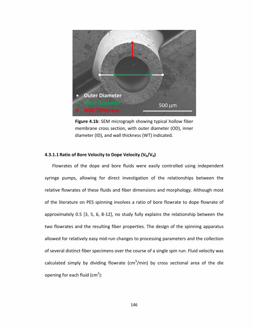
4.3.1.1 Ratio of Bore Velocity to Dope Velocity (Vb/Vd)
Flowrates of the dope and bore fluids were easily controlled using independent
syringe pumps, allowing for direct investigation of the relationships between the
relative flowrates of these fluids and fiber dimensions and morphology. Although most
of the literature on PES spinning involves a ratio of bore flowrate to dope flowrate of
approximately 0.5 [3, 5, 6, 8-12], no study fully explains the relationship between the
two flowrates and the resulting fiber properties. The design of the spinning apparatus
allowed for relatively easy mid-run changes to processing parameters and the collection
of several distinct fiber specimens over the course of a single spin run. Fluid velocity was
calculated simply by dividing flowrate (cm3/min) by cross sectional area of the die
opening for each fluid (cm2):
500 µm
• Outer Diameter• Inner Diameter• Wall Thickness
Figure 4.1b: SEM micrograph showing typical hollow fiber membrane cross section, with outer diameter (OD), inner diameter (ID), and wall thickness (WT) indicated.
146

𝑽𝑽𝒃𝒃 = 𝑸𝑸𝒃𝒃0.25𝜋𝜋𝑑𝑑𝑖𝑖2
𝑽𝑽𝒅𝒅 = 𝑸𝑸𝒅𝒅𝟎𝟎.𝟐𝟐𝟐𝟐𝟐𝟐(𝑫𝑫𝟐𝟐− 𝒅𝒅𝒐𝒐
𝟐𝟐)
where Qb, Qd, Vb and Vd are the flowrates and velocities of the bore fluid and the dope
fluid, respectively. D is the outer diameter of the spinneret capillary, while do and di are
the outer and inner diameters of the microtubing through which the bore fluid flows, as
shown in Figure 2.3. The processing parameters for these studies are reported in Table
4.2, with the dope flowrate fixed at 3.4 cm3/min. The ratio of flowrates (bore flowrate
to dope flowrate) used for these experiments ranged from 0.11 to 0.88, which is
consistent with the ratio value of approximately 0.5 that is commonly encountered in
the literature.
Table 4.2: Processing parameters for Vb/Vd, air gap, and draw down ratio
experiments.
Process Parameters
Experiment Vb/Vd Air Gap Draw Down Ratio
Spinning Solution PES/DMAc PES/DMAc PES/DMAc
Polymer Concentration 30 wt.% 30 wt.% 30 wt.%
Bore Fluid 70 wt.% DMAc 70 wt.% DMAc 70 wt.% DMAc
Coagulation Bath Deionized water Deionized water Deionized water
Dope Flowrate (cm3/min) 3.40 2.70 1.36 – 3.40
Bore Flowrate (cm3/min) 0.38 – 3.0 1.50 0.75 – 1.90
Vb/Vd 0.5 – 5.0 2.5 2.5
Air Gap (cm) 2 2 – 7 4
Draw Down Ratio 1.0 1.0 1.0 – 2.5
[4.2]
[4.1]
147

Dopes composed of 30 wt.% PES in DMAc were prepared employing the
procedure described in Section 2.3.2.1 and subsequently used to produce the hollow
fibers studied in this experiment. PES hollow fibers were spun, solvent exchanged, and
dried using the methods described in Section 2.3.2.2. Ten short lengths of fiber were cut
from various parts of the fiber spool and the outer and inner diameters were measured
using calipers and an optical microscope, respectively. One additional fiber sample was
immersed in liquid nitrogen and fractured using tweezers for SEM imaging.
148
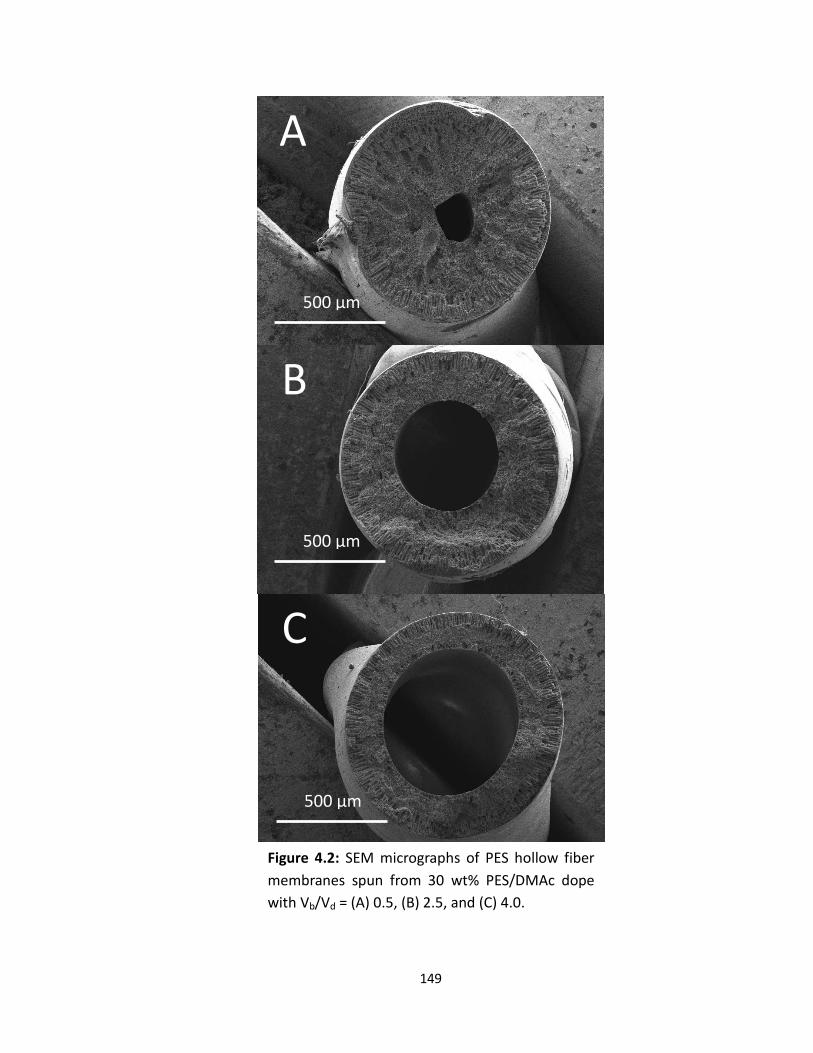
Figure 4.2: SEM micrographs of PES hollow fiber membranes spun from 30 wt% PES/DMAc dope with Vb/Vd = (A) 0.5, (B) 2.5, and (C) 4.0.
A
B
C
500 µm
500 µm
500 µm
149

Figure 4.2 presents a series of cross sections for hollow fibers that were spun
with various bore flowrates (i.e. various Vb/Vd ratios). An examination of the SEM
micrographs showed a direct relationship between the outer and inner diameters of the
hollow fibers with varying Vb/Vd ratio, and a decrease in the wall thickness as the Vb/Vd
ratio was increased. A plot of outer and inner diameters and membrane wall thickness
versus Vb/Vd is shown in Figure 4.3. The data indicated an increase in the outer diameter
of the hollow fiber with increasing velocity ratio (i.e. increasing bore flowrate). The inner
bore diameter of the hollow fiber also increased with Vb/Vd, with a higher slope. The
difference in the slope of the trend lines resulted in a steady decrease in wall thickness
as it related to Vb/Vd. The increased flow inside the bore with increasing Vb expanded
the inner dope surface, and the free outer surface of the fiber expanded across the air
gap in response, thereby increasing the outer diameter of the fiber while simultaneously
reducing the wall thickness. The observed decrease in the wall thickness of the hollow
fiber reflects the material balance of the flowing system (i.e. moving reference frame).
As the inner and outer diameters of the fiber are increased (and assuming the pore
structure remains consistent), the wall thickness of the membrane must necessarily
decrease in order to satisfy the material balance.
150

4.3.1.2 Air Gap Distance
The spinline design also allowed for the study of the effect of the vertical gap
distance between the extrusion die and the surface of the coagulation bath (i.e. the air
gap) and its influence on fiber dimensions and morphology. Direct changes to the air
gap were enabled by mounting the spinneret on a lab-jack; this allowed for several data
points to be collected over the course of a single spin run. The processing parameters
that were controlled to examine the effect of the air gap on the fiber dimensions and
morphology are presented in Table 4.2. For this experiment, Vb/Vd was held constant at
2.5 and draw down ratio (i.e the ratio of take-up velocity to the dope velocity at the die)
0.0
0.2
0.4
0.6
0.8
1.0
1.2
1.4
0 1 2 3 4 5
Aver
age
Dia
met
er (m
m)
Vb/Vd
Outer Diameter
Inner Diameter
Wall Thickness
Figure 4.3: Relationship between fiber dimensions and Vb/Vd for hollow fibers spun from 30 wt% PES/DMAc dope using a 70 wt% DMAc/water bore fluid and a pure water coagulation bath (n = 10 for each fiber sample).
151

was held at 1.0. Again, ten fiber samples were cut from various parts of the hollow fiber
spool and measured for their OD and ID. One fiber sample was also immersed in liquid
nitrogen and fractured for SEM imaging of the cross-section. No significant changes
were expected to be observed in the dimensions of the final hollow fibers, since the
flowrates of the two fluids, geometry of the die, and the draw down ratio were all held
constant. Additionally, there was sufficient draw on the fiber that, even at the largest air
gaps, the influence of gravity was negligible compared to the drawing force imposed by
the take-up godet. The primary expectation of this experiment was to observe the effect
of varying the air gap residence time that the nascent fiber spent in contact solely with
the solvent-rich bore fluid prior to being immersed in the deionized water coagulation
bath.
The relationships between the fiber dimensions and the air gap, while holding all
other processing parameters constant, are shown in Figure 4.4. It is clear from these
data that changing the air gap length in the range tested did not appreciably change the
measured dimensions of the hollow fiber. The effect of changing the air gap appeared to
be primarily morphological for this process, with the SEM micrographs indicating a
substantially larger pore size across the membrane substructure for the 7 cm air gap as
compared to the 3 cm air gap, as shown in Figure 4.5. This result can be attributed to
the longer time that the nascent fiber spends in contact with only the solvent-rich bore
fluid for the 7 cm air gap. The longer residence time in the air gap allowed more time for
phase inversion to progress at the inner surface owing to ingress of the solvent-rich
bore fluid.
152

This led to extended delayed demixing, which resulted in the emergence of larger
polymer-lean droplets in the substructure before the morphology was fully solidified
when the fiber entered the coagulation bath. With everything else being held equal, an
increase in the air gap distance from 3 cm to 7 cm more than doubled the residence
time (from 0.39 s to 0.81 s) during which delayed demixing occurred, which resulted in a
significant change in fiber morphology. The observed result is consistent with prior work
by Chung et al., who reported a comparable change in morphology for air gap spun PES
hollow fibers compared to fibers spun with no air gap exposure (i.e. wet spun fibers) [5].
0.0
0.2
0.4
0.6
0.8
1.0
1.2
2 3 4 5 6 7 8
Aver
age
Dia
met
er (m
m)
Air gap (cm)
Outer Diameter
Inner Diameter
Wall Thickness
Figure 4.4: Relationship between fiber dimensions and air gap distance for hollow fibers spun from 30 wt% PES/DMAc dope using a 70 wt% DMAc/water bore fluid and a pure water coagulation bath (n = 10 for each fiber sample).
153
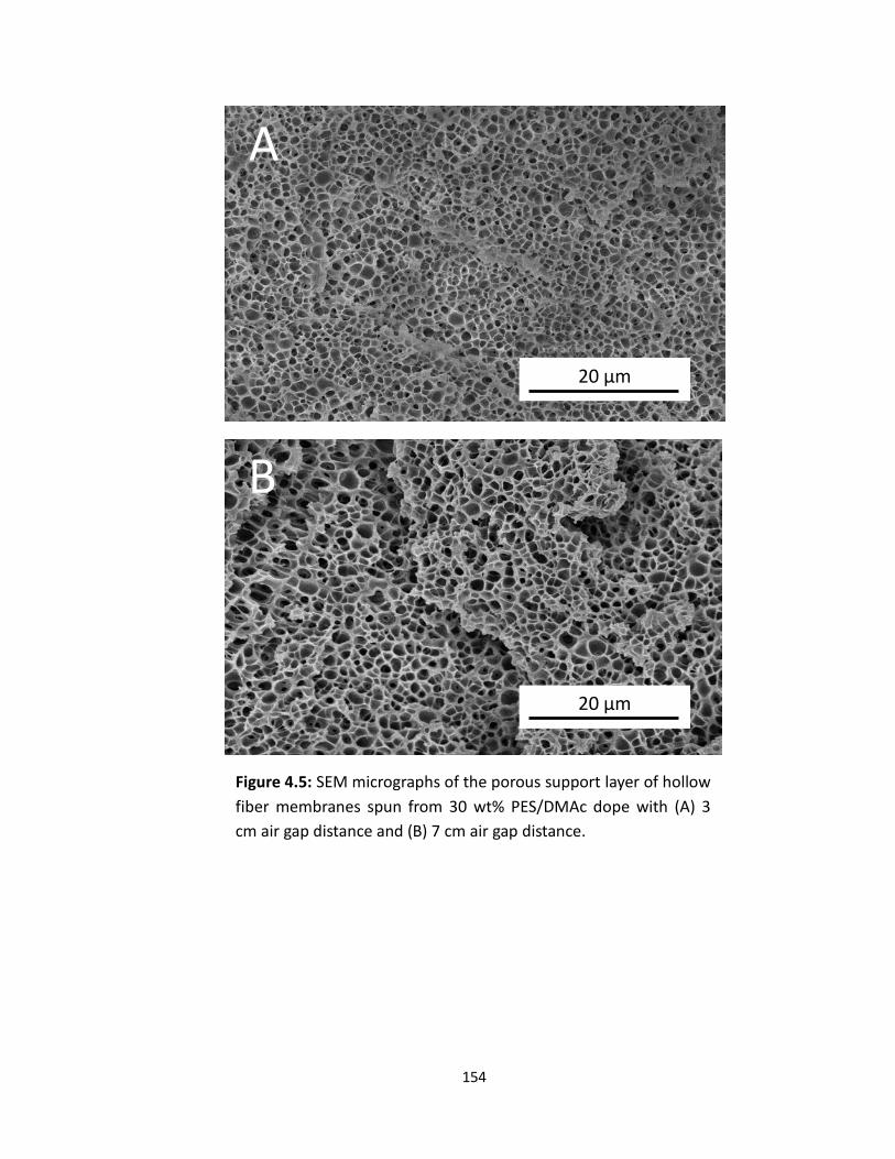
Figure 4.5: SEM micrographs of the porous support layer of hollow fiber membranes spun from 30 wt% PES/DMAc dope with (A) 3 cm air gap distance and (B) 7 cm air gap distance.
20 µm
20 µm
A
B
154

4.3.1.3 Ratio of Take-up Velocity to Dope Velocity (Draw Down Ratio)
The draw down ratio (DDR) was examined to determine its effect on PES hollow
fiber properties. The DDR was defined in this work as the ratio of the take up velocity at
the godet (Vg) to the velocity of the dope as it exits the die (Vd). Two different methods
for adjusting DDR during the spinning process were possible using the hollow fiber
spinning system. DDR could be changed either by increasing the take-up speed on the
godet rollers or by holding the take-up speed constant and adjusting the dope/bore
flowrates at the spinneret. For the purposes of these experiments, the draw down ratio
was adjusted solely by changing the flowrates of the two fluids (at fixed Vb/Vd), while
the take-up speed on the godet and the air gap distance were held constant.
Additionally, the rotational velocity of the winder was calibrated to be exactly the same
as that of the take-up godet. This was done to ensure that no further draw was imposed
on the fiber between the godet and the winder.
When melt spinning solid fiber, conservation of volume dictates that, if all other
processing parameters are held constant, the final fiber diameter will be inversely
proportional to the square root of the draw down ratio. Despite the increase in
complexity that comes from the multi-front phase-inversion solution process as
compared to melt spinning solid fiber, it was hypothesized that a similar trend might be
expected for the production of hollow fibers. The processing parameters for this
experiment are shown in Table 4.2. All of the parameters that were held constant in this
study were chosen based on the prior experiments detailed above.
155
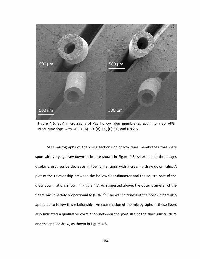
SEM micrographs of the cross sections of hollow fiber membranes that were
spun with varying draw down ratios are shown in Figure 4.6. As expected, the images
display a progressive decrease in fiber dimensions with increasing draw down ratio. A
plot of the relationship between the hollow fiber diameter and the square root of the
draw down ratio is shown in Figure 4.7. As suggested above, the outer diameter of the
fibers was inversely proportional to (DDR)1/2. The wall thickness of the hollow fibers also
appeared to follow this relationship. An examination of the micrographs of these fibers
also indicated a qualitative correlation between the pore size of the fiber substructure
and the applied draw, as shown in Figure 4.8.
Figure 4.6: SEM micrographs of PES hollow fiber membranes spun from 30 wt% PES/DMAc dope with DDR = (A) 1.0, (B) 1.5, (C) 2.0, and (D) 2.5.
500 µm 500 µm
500 µm500 µm
156

Similar to the effect of decreasing the air gap, a decrease in pore size was observed with
increasing draw ratio. It is an interesting trend, as intuition would suggest that higher
draw could compact or extend pores by deforming them via mechanical means after
coagulation. However, the shape of the pores did not change in any meaningful way
with higher draw, only the size, suggesting that the observed variation in pore size was
established before the pore structure was set by coagulation and the pores were not
mechanically stretched or altered after this point. A higher draw has a similar effect on
the pore structure as a decrease in the air gap distance, as it shortens the relative air
0.0
0.1
0.2
0.3
0.4
0.5
0.6
0.7
0.8
0.9
1.0
1 1.1 1.2 1.3 1.4 1.5 1.6
Aver
age
Dia
met
er (m
m)
(DDR)1/2
Outer Diameter
Inner Diameter
Wall Thickness
Figure 4.7: Relationship between fiber dimensions and the square root of draw down ratio for hollow fiber membranes spun from 30 wt% PES/DMAc dope, with 70 wt% DMAc/water bore fluid and deionized water coagulation bath (n = 10 for each fiber sample).
157

gap residence time between the die exit and coagulation. This reduces the time
available for coarsening of the polymer lean droplets (from 0.41 s to 0.59 s), resulting in
a tighter pore structure at higher draw down rates.
20 µm
A
20 µm
B
20 µm
C
20 µm
D
Figure 4.8: SEM micrographs of porous substructure of PES hollow fiber membranes spun from 30 wt% PES/DMAc dope with DDR = (A) 1.0, (B) 1.5, (C) 2.0, and (D) 2.5.
158

4.3.2 Gas Separation Properties of Hollow Fiber Membranes 4.3.2.1 Baseline Permeance and Selectivity of Hollow Fiber Membranes
The results of the experiments described in the previous sections were used to
choose a set of hollow fiber processing conditions for the production of membranes
suitable for gas transport studies. The spinning parameters that were employed to
produce the hollow fiber membranes for gas separation experiments are shown in Table
4.3. These parameters were found to produce hollow fibers with a dense separating
layer, relatively low occurrence of macrovoids, a sponge-like porous substructure, and a
porous inner wall of the hollow fiber. The solvent that was used for hollow fiber
spinning was NMP, which was determined through flat sheet studies in Chapter 3 to
have no significant impact on either the viscosity of the dope or the morphology of the
resulting polymeric membranes as compared to DMAc.
159

Table 4.3: Processing parameters used for the production of hollow fiber membranes for gas separation testing. Process Parameters Value
Spinning Solution PES/NMP, PES/NMP/MWCNT,
PES/NMP/Carbon Black
Polymer Concentration (by weight in solvent) 30 wt.%
Filler Concentration (by weight in polymer) 0 – 0.5 wt.%
Bore Fluid (wt.%) 70/30 (Solvent:H2O)
Coagulation Bath Deionized water
Spinneret Annulus Diameter (mm) 1.0
Bore Needle Dimensions (do, di) 0.508, 0.254 mm
Dope Flowrate (cm3/min) 2.5
Bore Flowrate (cm3/min) 0.75 – 1.90
Vb/Vd 2.5
Air Gap (cm) 4
Draw Down Ratio 2.0
Number of Fibers in HFM Module
Applied pressure difference (∆P; psi)
10
29
The baseline gas separation performance of PES and PSf hollow fiber membranes
was measured and compared to that of the flat sheet membranes, both with and
without PDMS caulking. All fibers were spun using the parameters presented in Table
4.3 and were then subjected to solvent exchange and drying per the procedures
described in Section 2.3.2.2. The permeance and ideal selectivity of the unfilled PES and
PSf fibers in both the neat and PDMS caulked states were measured at an applied
pressure difference of 29 psi, using the hollow fiber membrane module preparation and
testing methods described in Section 2.4.1.
160
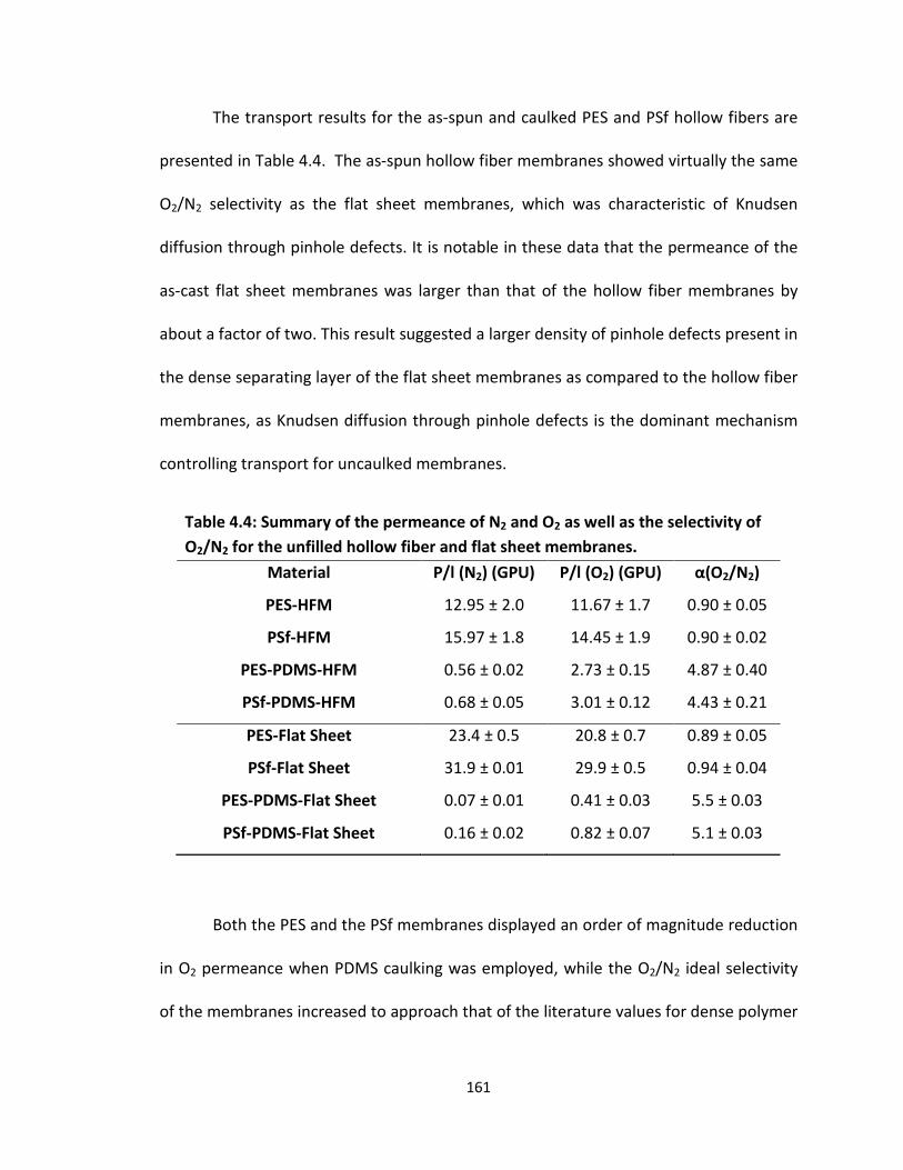
The transport results for the as-spun and caulked PES and PSf hollow fibers are
presented in Table 4.4. The as-spun hollow fiber membranes showed virtually the same
O2/N2 selectivity as the flat sheet membranes, which was characteristic of Knudsen
diffusion through pinhole defects. It is notable in these data that the permeance of the
as-cast flat sheet membranes was larger than that of the hollow fiber membranes by
about a factor of two. This result suggested a larger density of pinhole defects present in
the dense separating layer of the flat sheet membranes as compared to the hollow fiber
membranes, as Knudsen diffusion through pinhole defects is the dominant mechanism
controlling transport for uncaulked membranes.
Table 4.4: Summary of the permeance of N2 and O2 as well as the selectivity of O2/N2 for the unfilled hollow fiber and flat sheet membranes.
Material P/l (N2) (GPU) P/l (O2) (GPU) α(O2/N2)
PES-HFM 12.95 ± 2.0 11.67 ± 1.7 0.90 ± 0.05
PSf-HFM 15.97 ± 1.8 14.45 ± 1.9 0.90 ± 0.02
PES-PDMS-HFM 0.56 ± 0.02 2.73 ± 0.15 4.87 ± 0.40
PSf-PDMS-HFM 0.68 ± 0.05 3.01 ± 0.12 4.43 ± 0.21
PES-Flat Sheet 23.4 ± 0.5 20.8 ± 0.7 0.89 ± 0.05
PSf-Flat Sheet 31.9 ± 0.01 29.9 ± 0.5 0.94 ± 0.04
PES-PDMS-Flat Sheet 0.07 ± 0.01 0.41 ± 0.03 5.5 ± 0.03
PSf-PDMS-Flat Sheet 0.16 ± 0.02 0.82 ± 0.07 5.1 ± 0.03
Both the PES and the PSf membranes displayed an order of magnitude reduction
in O2 permeance when PDMS caulking was employed, while the O2/N2 ideal selectivity
of the membranes increased to approach that of the literature values for dense polymer
161
film [13]. The large reduction in membrane permeance and increase in ideal selectivity
was consistent with a change in the dominant diffusion mechanism across the
membrane from Knudsen diffusion to solution diffusion. Therefore, it can be concluded
from these data that the PDMS caulking procedure effectively repaired the pinhole
defects in the hollow fiber membrane dense separating layer.
It is also notable in these membranes that, for both polymers that were
examined, the hollow fiber membranes showed permeance that was nearly an order of
magnitude higher than the flat sheet membranes when caulked with PDMS. The larger
permeance that was observed in the hollow fiber membranes was accompanied by
slightly lower O2/N2 ideal selectivity. The transport properties that were observed for
these membranes were consistent with the solution diffusion mechanism, with the ideal
selectivity approaching that of a dense film membrane owing to the caulking of the
pinhole defects by application of PDMS. Contrary to Knudsen diffusion, wherein the
dominant driver of permeance is the number density of channels (i.e. pinhole defects)
through which the gas can flow, when solution diffusion dominates, the permeance is
controlled by the thickness of the dense separating layer of the membrane, as well as
the PDMS caulking layer. The permeation resistance due to the PDMS coating is minimal
compared to that of the dense separating layer, since PDMS is well known to be one of
the most permeable polymers in existence [14]. Therefore, the generally higher
permeance that was observed for the hollow fiber membranes prepared in this study is
likely the result of a reduction in the thickness of the dense separating layer in the
hollow fiber membranes as compared to their flat sheet analogs.
162
PSf hollow fiber membranes showed a higher permeance as compared to PES in
both the as-spun and PDMS caulked state. This effect was also observed previously in
the flat sheet membrane transport studies. The larger permeance across the as-spun PSf
hollow fiber (as compared to PES) was most probably the result of a larger areal density
of pinhole defects being formed in the dense separating layer of the membrane, a result
that was previously observed for the analogous flat sheet membranes. Upon caulking,
the PSf fibers showed gas selectivities consistent with successful repair of the pinhole
defects. The higher permeance observed for caulked PSf compared to PES is consistent
with the higher fractional free volume inherent to the dense separating layer of the
PSf polymer [13]. However, it could also be a result of differences in the thickness
of the dense separating layer in these membranes, which could result from
differences in the dynamics of the phase inversion process. In order to deconvolute
these contributions, further experiments would be necessary to fully characterize the
thickness of the dense separating layer in the fibers, and its relation to spinning
conditions and measured gas transport.
Overall, the hollow fiber membrane spinning conditions could be further
optimized to render hollow fiber transport performance competitive with that reported
in literature and achieved with commercial hollow fiber membranes. Both the ideal gas
selectivity as well as the membrane permeance can be improved by optimizing various
processing parameters. For example, the selectivity of the as-spun membrane can be
improved by tailoring the dope and bore fluid compositions in order to produce a
defect-free dense separating layer. In an ideal hollow fiber membrane, the dense
163

separating layer would be formed with no pinhole defects. This is an incredibly
challenging goal to reach, but there are methods that can produce membranes with a
defect-free dense separating layer. One strategy to prevent or minimize the formation
of pinhole defects in polymeric membranes is through the introduction of volatile non-
solvent additives, such as methanol or ethanol, into the polymer dope solution [15]. The
addition of these additives leads to local phase inversion at the membrane surface due
to solvent evaporation in the air gap (i.e. prior to bulk coagulation), which aids in the
formation of a dense separating layer that is both thin and free of pinhole defects.
The improvements that can be made in the ideal selectivity of the membrane are
generally less significant, however, than the improvements that can be achieved in the
membrane permeance. In the membrane community, much focused research is
conducted in order to increase the permeance of gas separation membranes while
maintaining selectivity at an acceptable level [11, 16, 17]. There are multiple methods
that are generally employed to achieve this result. The most common approach is the
optimization of dope formulation and processing conditions in order to form the
thinnest dense separating layer possible. Studies by Chung et al. have demonstrated the
ability to produce PES hollow fiber membranes with dense separating layers as thin as
474 Å by incorporating non-solvent additives into the polymer spinning dope [18].
Hollow fiber membranes produced in Chung’s work were able to achieve permeance
values of 9.6 GPU while maintaining an O2/N2 ideal selectivity of 5.8. These values
approach a common industry standard for hollow fiber permeance of >10 GPU [19],
while maintaining an ideal selectivity of the PES dense film.
164

4.3.3 Effect of Multiwall Carbon Nanotubes (MWCNT) Addition
In Chapter 3 of this work, it was reported that the incorporation of MWCNTs
decreased the permeance and increased the ideal selectivity of flat sheet membrane
coupons by suppressing the formation of pinhole defects in the dense separating layer
of the membrane during phase inversion. The studies presented in this chapter extend
those results by considering analogous MWCNT-loading experiments for hollow fiber
membranes. The dopes that were used for these experiments were produced with the
same formulation approach as the flat sheet membranes studied in Chapter 3; the
specific spinning conditions for the hollow fibers are detailed in Table 4.3. The objective
of these experiments was to determine whether or not the pinhole elimination
observed with MWCNT incorporation translated from the flat sheet PES and PSf
membrane coupons to hollow fiber membranes.
SEM micrographs of both the unfilled PES hollow fiber membrane as well as the
PES membrane loaded with 0.1 wt.% MWCNT are shown in Figure 4.9a. Although they
are not easily visible in the SEM micrographs, it is clear that the hollow fibers contain a
dispersion of MWCNTs, due to the macroscopic change in color from white to gray
(Figure 4.9b). An examination of the micrographs revealed only a minimal difference in
morphology, as was the case with the flat sheet membranes.
165

Figure 4.9a: SEM micrographs of hollow fiber membranes spun from dope composed of 30 wt.% PES in NMP (left) and dope composed of 30 wt.% PES in NMP with a MWCNT loading of 0.1 wt.% (right).
500 µm 500 µm
20 20 100 µm 100 µm
Figure 4.9b: Macroscopic comparison between neat PES HFM (top) and PES HFM loaded with 0.1 wt.% MWCNT (bottom)
166
10 mm
The outer surfaces of the fibers, which were exposed to the deionized water coagulation
bath, showed a well-defined dense separating later with finger-like macrovoids
extending below the surface. The majority of the wall thickness for both hollow fiber
membranes was composed of a sponge-like porous substructure. The main difference
that was observed in the morphologies of the two fibers was at the inner wall of the
fibers, which were phase-inverted in contact with the solvent-rich bore fluid. Similar to
the flat sheet membrane results, the PES-0.1MWCNT hollow fiber membrane showed
small teardrop-shaped macrovoids at the lumen surface, whereas no macrovoids were
observed in the unfilled PES membrane. No changes to the hollow fiber processing
were deemed necessary, because this difference in PES and PES-MWCNT membrane
morphology was also observed in the flat sheet membranes that were phase-inverted in
70 wt.% NMP in deionized water. These (flat sheet) membranes retained a porous
surface layer despite the small macrovoid formation, so the practical effect of the
macrovoids on the membrane properties was considered to be negligible.
4.3.3.1 Effect of Filler Loading on PES-MWCNT Mixed Matrix HFM Permselectivity
In Chapter 3, the permeation properties of flat sheet PES-MWCNT mixed matrix
membranes were examined at various MWCNT loadings. Through those experiments, it
was concluded that the MWCNTs suppressed the formation of pinhole defects possibly
by entangling with the polymer chains during phase inversion. Analogous transport
experiments were conducted using hollow fiber membrane modules. Plots of the
permeance and ideal selectivity of the hollow fiber membranes versus MWCNT loading
for the as-spun PES-MWCNT hollow fibers are shown in Figures 4.10a and 4.10b,
167
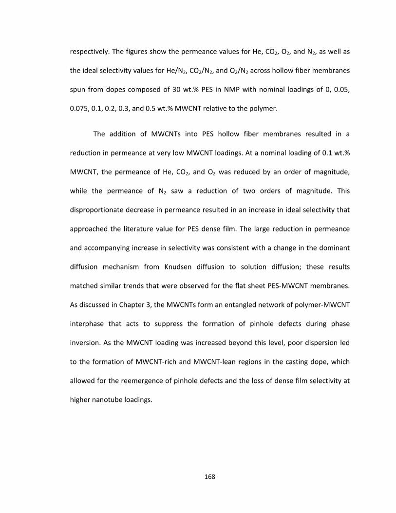
respectively. The figures show the permeance values for He, CO2, O2, and N2, as well as
the ideal selectivity values for He/N2, CO2/N2, and O2/N2 across hollow fiber membranes
spun from dopes composed of 30 wt.% PES in NMP with nominal loadings of 0, 0.05,
0.075, 0.1, 0.2, 0.3, and 0.5 wt.% MWCNT relative to the polymer.
The addition of MWCNTs into PES hollow fiber membranes resulted in a
reduction in permeance at very low MWCNT loadings. At a nominal loading of 0.1 wt.%
MWCNT, the permeance of He, CO2, and O2 was reduced by an order of magnitude,
while the permeance of N2 saw a reduction of two orders of magnitude. This
disproportionate decrease in permeance resulted in an increase in ideal selectivity that
approached the literature value for PES dense film. The large reduction in permeance
and accompanying increase in selectivity was consistent with a change in the dominant
diffusion mechanism from Knudsen diffusion to solution diffusion; these results
matched similar trends that were observed for the flat sheet PES-MWCNT membranes.
As discussed in Chapter 3, the MWCNTs form an entangled network of polymer-MWCNT
interphase that acts to suppress the formation of pinhole defects during phase
inversion. As the MWCNT loading was increased beyond this level, poor dispersion led
to the formation of MWCNT-rich and MWCNT-lean regions in the casting dope, which
allowed for the reemergence of pinhole defects and the loss of dense film selectivity at
higher nanotube loadings.
168

0.1
1.0
10.0
100.0
0.00 0.10 0.20 0.30 0.40 0.50
Perm
eanc
e (G
PU)
MWCNT Loading (Wt.%)
He
CO2
O2
N2
He
CO2
O2
N2
Figure 4.10a: Plot of He, CO2, O2, and N2 permeance against MWCNT loading for PES-MWCNT mixed matrix hollow fiber membranes. Connecting lines provided as a guide for the eye (n = 3 for each composition).
169
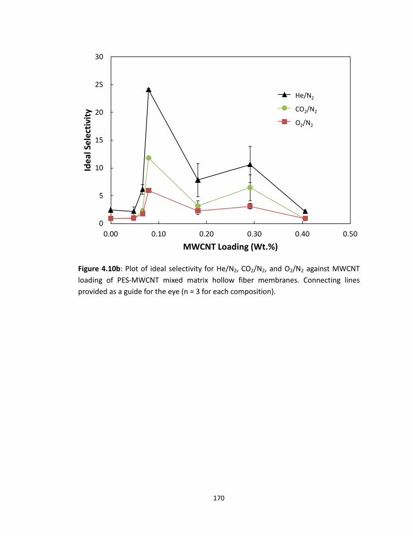
0
5
10
15
20
25
30
0.00 0.10 0.20 0.30 0.40 0.50
Idea
l Sel
ectiv
ity
MWCNT Loading (Wt.%)
He/N2
CO2/N2
O2/N2
He/N2
CO2/N2
O2/N2
Figure 4.10b: Plot of ideal selectivity for He/N2, CO2/N2, and O2/N2 against MWCNT loading of PES-MWCNT mixed matrix hollow fiber membranes. Connecting lines provided as a guide for the eye (n = 3 for each composition).
170

Table 4.5 shows a comparison of permeance results for unfilled PES (and PSf)
membranes that were caulked with PDMS to PES-MWCNT mixed matrix membranes
prepared at a nominal MWCNT loading of 0.1 wt.%. The table shows that PDMS caulking
or adding MWCNTs at the optimum level (i.e. the loading level corresponding to the
observed peak in selectivity) resulted in permeance values on the same order of
magnitude. The membrane that had been prepared via PDMS caulking showed higher
permeance, possibly due to the presence of a thinner dense separating layer, as well as
the potential influence of tortuosity on diffusion in the mixed matrix membrane. More
importantly, the O2/N2 ideal selectivity for both cases approached the literature value
for dense film selectivity. The fact that both membrane preparations independently
produced the same effects in terms of permeance and ideal selectivity of these
membranes further supports the hypothesis that the MWCNTs improve the selectivity
of the membranes by preventing the formation of pinhole defects in the dense
separating layer.
Table 4.5: O2/N2 transport properties for MWCNT-loaded hollow fiber membranes as compared to unfilled caulked membranes.
Material P/l (N2) (GPU) P/l (O2) (GPU) α(O2/N2)
PES-PDMS-HFM 0.56 ± 0.02 2.73 ± 0.15 4.87 ± 0.40
PSf-PDMS-HFM 0.68 ± 0.05 3.01 ± 0.12 4.43 ± 0.21
PES-0.1 wt.% MWCNT-HFM* 0.21 ± 0.12 1.27 ± 0.16 5.93 ± 0.24
PSf-0.1 wt.% MWCNT-HFM† 0.25 ± 0.08 1.24 ± 0.12 4.78 ± 0.22
*Actual composition is 0.079 wt.%†Actual composition is 0.085 wt%
171

Figures 4.11a and 4.11b show the permeance and ideal selectivity, respectively, versus
MWCNT loading for PES-MWCNT hollow fiber membranes that were caulked with
PDMS. Figure 4.11a showed a decrease in the permeance of all measured gases as
MWCNT loading was increased. This decrease, however, was not accompanied by a net
increase in the ideal selectivity, Figure 4.11b, of any of the measured gas pairs. Instead,
as the MWCNT loading was increased, the ideal selectivity of the membrane stayed
approximately constant near the dense film selectivity of the membrane. This lack of
change in selectivity reaffirmed the hypothesis that the MWCNTs improved the
selectivity of the as-spun membranes through the suppression of pinhole defects. At
MWCNT loadings that were lower or higher than the “optimum” MWCNT loading that
was observed at 0.1 wt.%, the PDMS caulk acted to repair the pinhole defects that
formed in the MWCNT-lean regions of the dense separating layer. These MWCNT-lean
regions were formed at low MWCNT loadings due to MWCNTs being spaced too far
apart to form an entangled network, and at high MWCNT loadings due to
inhomogeneous dispersion, as was previously discussed in Chapter 3. It is also notable
that a local minimum in membrane permeance is evident at a nominal loading of 0.1
wt.% MWCNT. This is most likely caused by an increase in tortuosity in the membrane,
which results from the homogeneous dispersion of MWCNTs at this loading.
172

0.01
0.10
1.00
10.00
0.00 0.10 0.20 0.30 0.40 0.50
Perm
eanc
e (G
PU)
MWCNT Loading (Wt.%)
HeCO2O2N2
He CO2 O2 N2
Figure 4.11a: Plot of He, CO2, O2, and N2 permeance against MWCNT loading for PDMS caulked PES-MWCNT mixed matrix hollow fiber membranes. Connecting lines provided as a guide for the eye (n = 3 for each composition).
173

0
5
10
15
20
25
30
0.00 0.10 0.20 0.30 0.40 0.50
Idea
l Sel
ectiv
ity
MWCNT Loading (Wt.%)
He/N2
CO2/N2
O2/N2
He/N2
CO2/N2
O2/N2
Figure 4.11b: Plot of He/N2, CO2/N2, and O2/N2 ideal selectivity against MWCNT loading for PDMS caulked PES-MWCNT mixed matrix hollow fiber membranes. Connecting lines provided as a guide for the eye (n = 3 for each composition).
174

Table 4.6 shows a full comparison between flat sheet and hollow fiber
membranes for MWCNT-loaded PES and PSf membranes, both with and without PDMS
caulking. All samples showed very similar O2/N2 ideal selectivity values in both the flat
sheet and hollow fiber geometries, and all approach the literature value for ideal
selectivity of a dense film membrane. The measured gas permeance was found to be
higher in hollow fiber membranes but on the same order of magnitude of the flat
sheets, which was consistent with previous membranes that were discussed in this
chapter. The small differences in the gas permeance of these membranes is most likely
due to small differences in the thickness of the dense separating layer of the membrane,
since the dominant diffusion mechanism in all of these membranes was solution-
diffusion.
Table 4.6: O2/N2 transport properties for MWCNT-loaded flat sheet and hollow fiber membranes with and without PDMS caulking.
Material P/l (N2) (GPU) P/l (O2) (GPU) α(O2/N2)
PES-0.1 wt.% MWCNT-HFM* 0.21 ± 0.12 1.27 ± 0.16 5.93 ± 0.24
PSf-0.1 wt.% MWCNT-HFM† 0.25 ± 0.08 1.24 ± 0.12 4.78 ± 0.22
PES-0.1 wt.% MWCNT-PDMS-HFM* 0.10 ± 0.04 0.67 ± 0.21 6.40 ± 0.23
PSf-0.1 wt.% MWCNT-PDMS-HFM† 0.17 ± 0.01 0.87 ± 0.23 5.11 ± 0.21
PES-0.1 wt.% MWCNT-FS‡ 0.08 ± 0.03 0.44 ± 0.11 5.73 ± 0.89
PSf-0.1 wt.% MWCNT-FS• 0.21 ± 0.07 1.04 ± 0.13 4.89 ± 0.74
PES-0.1 wt.% MWCNT-PDMS-FS‡ 0.03 ± 0.01 0.20 ± 0.06 6.72 ± 0.28
PSf-0.1 wt.% MWCNT-PDMS-FS• 0.07 ± 0.03 0.39 ± 0.11 5.58 ± 0.20
*Actual composition is 0.079 wt.%†Actual composition is 0.085 wt.%
‡Actual composition is 0.091 wt.% •Actual composition is 0.089 wt.%
175

The measured similarities in permeance and ideal selectivity for the flat sheet and
hollow fiber membrane preparations reflect the close correspondence in formulation
and casting conditions that was maintained for both membrane geometries. The ability
to directly translate the gas transport properties of flat sheet membrane coupons to
hollow fiber membrane modules is very important to the development of future
membrane-based gas separation systems. Flat sheet membrane coupons can be
prepared more quickly and easily than hollow fiber membranes, so they allow efficient
experimentation as a basis to identify membrane formulations and processing strategies
that lead to useful gas separation properties, which can then be translated into the
hollow fiber geometry.
4.3.3.2 Effect of Filler Loading on PES-Carbon Black Mixed Matrix HFM Permselectivity
The effect of using carbon black as the inorganic filler was also studied for the
PES hollow fibers. This was done in order to compare and contrast its influence on the
permeance and selectivity of the membranes with that of the MWCNTs. The hollow
fibers that were tested in these experiments were spun from dopes that were prepared
using the procedure described in Section 2.3.2.1, with the processing parameters shown
in Table 4.3. A comparison of the permeance of N2 and O2 as well as the O2/N2 ideal
selectivity for unfilled PES and PES with 0.1 wt.% carbon black in both flat sheet coupons
and hollow fiber membranes is provided in Table 4.7.
176

Table 4.7: Comparison of the permeance of N2 and O2 and O2/N2 selectivity for PES filled with carbon black versus the unfilled PES membrane.
P/l (N2) (GPU) P/l (O2) (GPU) α(O2/N2)
23.4 ± 0.21 20.8 ± 0.16 0.89 ± 0.04
0.66 ± 0.12 0.52 ± 0.07 0.80 ± 0.02
12.95 ± 2.0 11.67 ± 1.7 0.90 ± 0.05
Material
PES-Flat Sheet
PES-0.1Carbon Black-FS‡
PES-HFM
PES-Carbon Black-HFM* 1.51 ± 0.20 1.21 ± 0.11 0.80 ± 0.05
*Actual composition is 0.089 wt%‡Actual composition is 0.091 wt.%
As discussed previously, the flat sheet unfilled membrane showed a higher permeance
compared to that of the hollow fiber membrane, although both membranes showed
selectivity consistent with Knudsen diffusion dominating in the dense selective layer. As
noted in Chapter 3, regarding PES and PSf flat sheet membranes loaded with carbon
black, the large reduction in permeance that is observed with no improvement in ideal
selectivity is likely a reflection of the low aspect ratio of the carbon black particles
(average particle size = 45 nm). It is hypothesized that they did not effectively entangle
with the polymer chains, and did not prevent the formation of pinhole defects, as was
observed with PES-MWCNT mixed matrix membranes. The carbon black particles
reduced the permeance of the membrane simply by obstructing the gas flow through
the pinhole defects to some extent. Therefore, Knudsen diffusion still predominated
through the pinhole defects that remained open or only partially obstructed, but overall
flow was reduced, since the primary driver of permeance in Knudsen diffusion is the
number density of channels available for diffusion.
177

A comparison of the permeance of N2 and O2 and the ideal selectivity of the gas
pair between PES and PES filled with 0.1 wt.% carbon black after PDMS caulking is
reported in Table 4.8. The membranes presented in this table were produced using the
same dope preparation, spinning procedures, and PDMS caulking method as all previous
hollow fiber membranes.
Table 4.8: Comparison of the permeance of N2 and O2 and O2/N2 selectivity of caulked PES hollow fibers filled with 0.1 wt.% carbon black to that of the unfilled membrane.
P/l (N2) (GPU) P/l (O2) (GPU) α(O2/N2)
12.95 ± 2.0 11.67 ± 1.7 0.90 ± 0.05
0.56 ± 0.02 2.73 ± 0.15 4.87 ± 0.40
Material
PES-HFM
PES-PDMS-HFM
PES-Carbon Black-HFM* 1.51 ± 0.20 1.21 ± 0.11 0.80 ± 0.05
PES-PDMS-Carbon Black-HFM* 0.081 ± 0.22 0.445 ± 0.38 5.50 ± 0.14
*Actual composition is 0.089 wt.%
After PES carbon black hollow fibers were caulked with PDMS, a further substantial
decrease in the permeance of both N2 and O2 was observed. This was accompanied by
an increase in the ideal selectivity of the membranes from 0.80, which reflects Knudsen
diffusion through pinhole defects, to 5.50, which approaches the dense film value for
PES[13]. This is consistent with all previous results herein concerning PES-carbon black
mixed matrix membranes. Since the reduction in permeance with the addition of carbon
black was due to the partial obstruction of pinhole defects, rather than the prevention
of their formation, Knudsen diffusion still predominated. However, after PDMS caulking
was applied to these membranes, the pinhole defects were repaired, resulting in a shift
178
to solution-diffusion transport that produced both a further reduction in permeance and
an increase in selectivity to inherent (dense film) levels.
4.4 Conclusions
A bench-scale, hollow fiber spinning system was designed, fabricated and
commissioned at the University of Kentucky Center for Applied Energy Research.
Through literature review and consideration of best practices, several processing
parameters were identified as having key influence over the hollow fiber membrane
dimensions and morphology. These processing parameters included the composition
and relative flowrates of both the HFM spinning dope and the bore fluid, the vertical air
gap distance between the spinneret and the coagulation bath, and the ratio of the take-
up velocity to the dope extrusion velocity (i.e. draw down ratio).
Appropriate hollow fiber membrane spinning dope and bore fluid compositions
were chosen based on flat sheet membrane morphology studies that were reported in
Chapter 3 of this work. In the current chapter, experiments were conducted in order to
further understand the influence of key processing parameters on the dimensions and
morphology of the hollow fiber membranes. These experiments were used to develop a
set of controlled processing parameters to consistently produce hollow fiber
membranes with a dense outer separating layer, short macrovoids, a sponge-like porous
substructure, and a porous wall on the lumen side of the fiber.
In addition to establishing key relationships between process parameters and the
morphological character of the resulting hollow fibers, experiments were conducted to
179

measure the gas transport properties of these membranes in the hollow fiber geometry.
These permeation experiments were conducted to first establish a baseline of gas
separation performance for the unfilled membranes, and then to examine the influence
of inorganic filler loading on the permeance and selectivity of the PES and PSf
membranes. The primary objective of these studies was to determine if the effects that
were observed in Chapter 3 for asymmetric flat sheet membrane coupons could be
extended to the hollow fiber geometry.
The addition of MWCNTs into a polymeric matrix at low loading increased the ideal
selectivity of the membrane to approach that of the literature value for a dense polymer
film. Coincident with this increase in the ideal selectivity was a decrease in the gas
permeance of the membrane. The increase in selectivity suggested that the MWCNTs
acted to suppress the formation of pinhole defects in the membrane by entangling with
the polymer chains to form a physical network of MWCNT-polymer interphase. In doing
so, the MWCNTs produced the same essential effect as PDMS caulking. This outcome
was also critical in the sense that it demonstrated the ability to directly translate the
results that were observed for the flat sheet coupons in Chapter 3. This was enabled by
the flat sheet membrane casting experiments being conducted specifically with an eye
toward future hollow fiber membrane spinning. The relatively straightforward scale up
to hollow fibers was critical not only for the results presented in this work, but also to
the development of future gas separation membranes, since flat sheet membranes
provide the possibility of more rapid investigation into potentially interesting membrane
formulations.
180

The incorporation of carbon black into the PES membrane was also examined, in
order to assess the generality of the outcomes observed with the introduction of low
levels of MWCNTs. Once again, carbon black reduced the permeance of all gases, but
did not result in an improvement in gas pair selectivity, apparently owing to the lower
aspect ratio of the carbon black particles. It is likely that the lower aspect ratio of the
carbon black particles (as compared to that of the carbon nanotubes) did not produce
the requisite entanglement between the filler and the polymer chains needed for
pinhole defect suppression during membrane casting. Instead, the carbon black particles
apparently reduced the permeance of the membrane by obstructing the pinhole
defects, rather than suppressing their formation.
The observation that a dispersion of multiwall carbon nanotubes in a polymeric
membrane matrix suppressed the formation of pinhole defects is the first of its kind. It is
also important to note that this effect was observed in both flat sheet membrane
coupons as well as hollow fiber membrane modules. The membrane fabrication process
still requires further optimization with regard to the thickness of the dense separating
layer of the membrane, as the permeance of the membranes presented in this work was
significantly lower than what is considered necessary for commercially viable
membranes. However, the ability to achieve what is essentially the same state as is
typically accomplished with PDMS caulking could lead to advancements in hollow fiber
membrane processing. Currently, when polymeric hollow fiber membrane modules are
manufactured, the PDMS caulking is conducted on each membrane module individually
in a separate and time-intensive post-processing step. The suppression of pinhole
181

surface defect formation via the incorporation of low levels of MWCNT’s offers a route
by which to eliminate this separate caulking step, thereby rendering membrane module
fabrication more efficient and less costly.
182
4.5 References
1. Peng, N., Widjojo, N., Sukitpaneenit, P., Teoh, M. M., Lipscomb, G. G., Chung, T.S., Lai, J. Y., Evolution of polymeric hollow fibers as sustainable technologies:Past, present, and future. Progress in Polymer Science, 2012. 37(10): p. 1401-1424.
2. Chen, C.-C., W. Qiu, S.J. Miller, and W.J. Koros, Plasticization-resistant hollowfiber membranes for CO2/CH4 separation based on a thermally crosslinkablepolyimide. Journal of Membrane Science, 2011. 382(1-2): p. 212-221.
3. Chung, T.S., Hu, X. D., Effect of air-gap distance on the morphology and thermalproperties of polyethersulfone hollow fibers. Journal of Applied Polymer Science,1997. 66(6): p. 1067-1077.
4. Chung, T.S., Kafchinski, E. R., The effects of spinning conditions on asymmetric6FDA/6FDAM polyimide hollow fibers for air separation. Journal of AppliedPolymer Science, 1997. 65(8): p. 1555-1569.
5. Chung, T.S., Z.L. Xu, and W.H. Lin, Fundamental understanding of the effect ofair-gap distance on the fabrication of hollow fiber membranes. Journal of AppliedPolymer Science, 1999. 72(3): p. 379-395.
6. Peng, N., Chung, T. S., The effects of spinneret dimension and hollow fiberdimension on gas separation performance of ultra-thin defect-free Torlon®hollow fiber membranes. Journal of Membrane Science, 2008. 310(1-2): p. 455-465.
7. Chung, T.S., E.R. Kafchinski, and P. Foley, Development of asymmetric hollow fibers from polyimides for air separation. Journal of Membrane Science, 1992. 75(1-2): p. 181-195.
8. Cao, C., Chung, Tai-Shung, Chen, Shing Bor, Dong, ZhengJun, The study ofelongation and shear rates in spinning process and its effect on gas separationperformance of Poly(ether sulfone) (PES) hollow fiber membranes. ChemicalEngineering Science, 2004. 59(5): p. 1053-1062.
9. Chung, T.S. and S.K. Teoh, The ageing phenomenon of polyethersulphone hollowfibre membranes for gas separation and their characteristics. Journal ofMembrane Science, 1999. 152(2): p. 175-188.
10. Chung, T.S., S.K. Teoh, and X.D. Hu, Formation of ultrathin high-performancepolyethersulfone hollow-fiber membranes. Journal of Membrane Science, 1997.133(2): p. 161-175.
11. Li, Y., C. Cao, T.-S. Chung, and K.P. Pramoda, Fabrication of dual-layerpolyethersulfone (PES) hollow fiber membranes with an ultrathin dense-selectivelayer for gas separation. Journal of Membrane Science, 2004. 245(1-2): p. 53-60.
12. Qin, J.J., Gu, J., Chung, T. S., Effect of wet and dry-jet wet spinning on the sheer-induced orientation during the formation of ultrafiltration hollow fibermembranes. Journal of Membrane Science, 2001. 182(1-2): p. 57-75.
183

Prasad, R., Shaner, R. L., Wijmans, J. G., Yampolskii, Y. P., Polymeric GasSeparation Membranes. 1994: CRC Press Inc.
14. Singh, A., Freeman, B. D., Pinnau, I., Pure and mixed gas acetone/nitrogenpermeation properties of polydimethylsiloxane PDMS. Journal of Polymer SciencePart B-Polymer Physics, 1998. 36(2): p. 289-301.
15. Clausi, D.T. and W.J. Koros, Formation of defect-free polyimide hollow fibermembranes for gas separations. Journal of Membrane Science, 2000. 167(1): p.79-89.
16. Li, F.Y., Y. Li, T.-S. Chung, H. Chen, Y.C. Jean, and S. Kawi, Development andpositron annihilation spectroscopy (PAS) characterization of polyamide imide(PAI)–polyethersulfone (PES) based defect-free dual-layer hollow fibermembranes with an ultrathin dense-selective layer for gas separation. Journal ofMembrane Science, 2011. 378(1-2): p. 541-550.
17. Li, Y., Chung, T. S., Xiao, Y., Superior gas separation performance of dual-layerhollow fiber membranes with an ultrathin dense-selective layer. Journal ofMembrane Science, 2008. 325(1): p. 23-27.
18. Chung, T., Teoh, S. K., Hu, X. D., Formation of ultrathin high-performancepolyethersulfone hollow-fiber membranes. Journal of Membrane Science, 1997.133: p. 161-175.
19. Lipscomb, G.G.L., Personal Communication, 2018.
184
13. Baker, R.W., Beckman, I. N., Cussler, E. L., Doshi, K, Henis, J. M. S., Koros, W. J.,Nakagawa, T., Paul, D. R., Petropoulos, J. H., Pinnau, I., Pixton, M. R., Plate, N,

Chapter 5: Conclusions and Future Work
5.1 Conclusions
Over the course of the work presented in this dissertation, the four primary
objectives that were described in Section 1.4 were executed. These four objectives
consisted of (i) the design, fabrication, and commissioning of a hollow fiber membrane
spinning line, (ii) the use of flat sheet membrane experiments to determine appropriate
dope and bore fluid compositions for hollow fiber spinning, (iii) the variation of HFM
processing parameters in order to examine their influence on the dimensions and
morphology of the produced fibers and to establish a set of standard operating
conditions, and (iv) the investigation of nanoscale filler incorporation on membrane
permeance and selectivity in both the flat sheet and hollow fiber geometries. The
conclusions that emerged from these experiments are summarized in the following
section. In addition, the experimental results led to a number of interesting research
questions for further investigation; these questions are discussed below.
5.1.1 Flat Sheet Membranes
Asymmetric flat sheet membranes were cast using non-solvent induced phase
inversion in order to study the influence of dope composition and coagulation medium
on the membrane morphology. These experiments were conducted to assess the phase-
inversion dynamics and establish appropriate conditions for flat sheet casting and
hollow fiber spinning. It was determined that dope solution compositions of 30 wt.%
polyethersulfone (PES) and 35 wt.% polysulfone (PSf) in N-methylpyrrolidone (NMP)
were appropriate for flat sheet and hollow fiber membrane fabrication, based on the
185
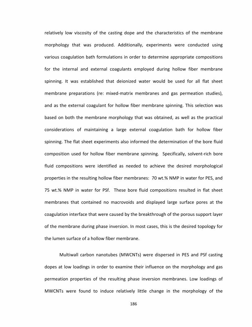
relatively low viscosity of the casting dope and the characteristics of the membrane
morphology that was produced. Additionally, experiments were conducted using
various coagulation bath formulations in order to determine appropriate compositions
for the internal and external coagulants employed during hollow fiber membrane
spinning. It was established that deionized water would be used for all flat sheet
membrane preparations (re: mixed-matrix membranes and gas permeation studies),
and as the external coagulant for hollow fiber membrane spinning. This selection was
based on both the membrane morphology that was obtained, as well as the practical
considerations of maintaining a large external coagulation bath for hollow fiber
spinning. The flat sheet experiments also informed the determination of the bore fluid
composition used for hollow fiber membrane spinning. Specifically, solvent-rich bore
fluid compositions were identified as needed to achieve the desired morphological
properties in the resulting hollow fiber membranes: 70 wt.% NMP in water for PES, and
75 wt.% NMP in water for PSf. These bore fluid compositions resulted in flat sheet
membranes that contained no macrovoids and displayed large surface pores at the
coagulation interface that were caused by the breakthrough of the porous support layer
of the membrane during phase inversion. In most cases, this is the desired topology for
the lumen surface of a hollow fiber membrane.
Multiwall carbon nanotubes (MWCNTs) were dispersed in PES and PSf casting
dopes at low loadings in order to examine their influence on the morphology and gas
permeation properties of the resulting phase inversion membranes. Low loadings of
MWCNTs were found to induce relatively little change in the morphology of the
186

membranes as compared to the unfilled casting system, with the presence of the tubes
leading to slightly longer and more pronounced macrovoids. A nominal loading of 0.1
wt.% MWCNT relative to the polymer resulted in a marked decrease in the permeance
of the resulting membrane and an O2/N2 selectivity that approached the literature value
for a dense polymer film. These two effects suggested that the presence of the
MWCNTs suppressed the formation of pinhole defects in the dense separating layer of
the membrane during phase inversion. This is a phenomenon that has not previously
been reported in the membrane literature. Further experiments were conducted with
PES membranes containing a dispersion of nanoscale carbon black as the filler. The
inclusion of carbon black resulted in a similarly large decrease in the permeance of the
membrane, but with no observed increase in ideal selectivity across the same range of
loading levels. It was hypothesized that the large aspect ratio of the MWCNTs caused
them to entangle with the polymer chains, forming a network of polymer-MWCNT
interphase which suppressed the formation of pinhole defects during membrane
solidification.
The observed effect, that a low loading of well-dispersed MWCNTs suppresses
the formation of pinhole defects in asymmetric gas separation membranes, is the first of
its kind. This discovery is important in the context of industrial gas separation
membrane fabrication, as the ability to form a defect-free asymmetric membrane could
result in the elimination of the PDMS caulking step typically required during the
preparation of membrane modules. This is notable because during commercial
membrane manufacturing, PDMS caulking is necessarily performed on individual
187

modules. The ability to directly produce defect-free asymmetric membranes has the
potential to significantly simplify the module manufacturing process by eliminating this
time-consuming step.
5.1.2 Hollow Fiber Membranes
A bench-scale, hollow fiber membrane spinning system was designed, fabricated
and commissioned at the University of Kentucky. A set of key processing parameters
were identified as having primary influence over the dimensions and morphology of the
hollow fiber membranes. These processing parameters included the relative flowrates
of the dope and bore fluid, the vertical air gap distance between the spinneret and the
coagulation bath, and the ratio of the take-up velocity to the dope velocity at the die
(i.e. draw down ratio). The hollow fiber spinning system was designed to allow
systematic and controlled variation of these processing parameters in order to assess
their impact on the resulting fiber dimensions and morphology. The results of the flat
sheet membrane studies were used to determine the dope composition, external
coagulation bath and bore fluid formulations that were used in the hollow fiber
membrane spinning experiments.
The effect of adding a dispersion of MWCNTs into the fiber spinning dope was
examined in order to determine if the pinhole suppression that was encountered in the
flat sheet experiments would also be observed in the hollow fiber membrane geometry.
This was accomplished by first establishing baseline permeation properties for unfilled
PES and PSf hollow fiber membranes, each with and without PDMS caulking. Both the
PES and PSf hollow fiber membranes showed high permeance and gas pair selectivities
188

that reflected Knudsen diffusion through pinhole defects prior to PDMS caulking. The
introduction of the PDMS coating led to a strong decrease in permeance (consistent
with filling of the pinholes), and the recovery of ideal selectivity values approaching
those of the dense polymer.
The transport properties of the unfilled membranes were compared to
membranes with a range of MWCNT loadings. The addition of MWCNTs at a nominal
loading of 0.1 wt.% showed a large decrease in permeance, coincident with a
restoration of the dense film selectivity, similar to the results that were obtained with
flat sheet membranes. This effect was not observed when incorporating a dispersion of
carbon black into the membrane matrix. Here again, these results suggested that the
MWCNTs suppressed the emergence of pinhole defects by entangling with the polymer
chains, thereby constraining the opening of surface gaps as the membrane solidified
from solution.
The observation that low level incorporation of MWCNTs can suppress the
formation of pinhole surface defects in hollow fiber membranes has not previously been
reported. In terms of the hollow fiber membranes produced in this study, the spinning
process requires further optimization in order to fully exploit this outcome. In
particular, it would be necessary to refine the spinning conditions to reduce the
thickness of the dense separating layer, as both the flat sheet and hollow fiber
membranes produced in this work showed permeance values that were significantly
lower than what is required for viable commercial use. As noted above, the introduction
189

of MWCNTs to directly suppress the formation of pinhole defects and achieve dense
film selectivity could lead to important efficiencies in hollow fiber membrane
manufacture by eliminating the time-consuming process of (PDMS) membrane caulking
during module fabrication.
5.2 Future Work
The observation that multiwall carbon nanotubes suppress the formation of
pinhole defects may be novel, but further research will be required to develop the
membranes that were produced in this work into viable commercial membranes. Some
of this future work involves the optimization of the processing parameters employed
during hollow fiber membrane spinning to enable the formation of a thinner dense
separating layer while maintaining overall membrane integrity. There is also the
potential research that can be conducted using the processing and testing apparatus
that were constructed in this work. Research possibilities include the study of a wider
range of matrix polymers and nanoscale filler elements than those that were discussed
here.
Additionally, the observation that MWCNTs suppress the formation of pinhole
defects in PES and PSf has prompted several other questions surrounding the exact
mechanism responsible for this effect as well as the enhancement of gas selectivity that
is achievable via the inclusion of MWCNTs. Future experiments should be conducted in
order to further probe the influence of aspect ratio and chemical compatibility of the
filler in an attempt to validate the hypothesis that was proposed herein with respect to
the mechanism by which MWCNTs suppress the formation of pinhole defects. One
190
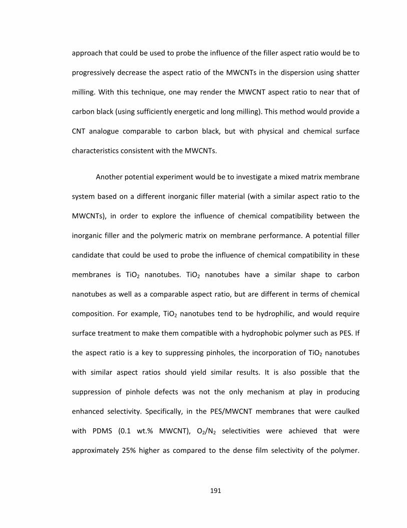
approach that could be used to probe the influence of the filler aspect ratio would be to
progressively decrease the aspect ratio of the MWCNTs in the dispersion using shatter
milling. With this technique, one may render the MWCNT aspect ratio to near that of
carbon black (using sufficiently energetic and long milling). This method would provide a
CNT analogue comparable to carbon black, but with physical and chemical surface
characteristics consistent with the MWCNTs.
Another potential experiment would be to investigate a mixed matrix membrane
system based on a different inorganic filler material (with a similar aspect ratio to the
MWCNTs), in order to explore the influence of chemical compatibility between the
inorganic filler and the polymeric matrix on membrane performance. A potential filler
candidate that could be used to probe the influence of chemical compatibility in these
membranes is TiO2 nanotubes. TiO2 nanotubes have a similar shape to carbon
nanotubes as well as a comparable aspect ratio, but are different in terms of chemical
composition. For example, TiO2 nanotubes tend to be hydrophilic, and would require
surface treatment to make them compatible with a hydrophobic polymer such as PES. If
the aspect ratio is a key to suppressing pinholes, the incorporation of TiO2 nanotubes
with similar aspect ratios should yield similar results. It is also possible that the
suppression of pinhole defects was not the only mechanism at play in producing
enhanced selectivity. Specifically, in the PES/MWCNT membranes that were caulked
with PDMS (0.1 wt.% MWCNT), O2/N2 selectivities were achieved that were
approximately 25% higher as compared to the dense film selectivity of the polymer.
191

This suggests that the MWCNTs serve an added separation function, beyond the
suppression of pinhole defects.
An additional mechanism that could be operative in the mixed matrix
membranes is molecular sieving through the interlayer spacing of the MWCNTs. This
mechanism has been suggested as a means by which MWCNTs can improve the
selectivity of PES mixed matrix membranes. The addition of MWCNTs into a flat sheet
PES matrix that had been caulked with PDMS has been previously demonstrated by
other investigators to result in an O2/N2 ideal selectivity of approximately 10, as
discussed in Chapter 3. One key difference in these earlier studies was the use of acid
purification and functionalization of the nanotubes prior to membrane casting in order
to better facilitate their adhesion into the PES matrix, while the experiments conducted
in this dissertation employed pristine nanotubes. Using surface-modified MWCNTs
could allow for better dispersion at higher loadings, potentially extending the pinhole
suppression effect while simultaneously introducing a greater contribution from
molecular sieving through the interlayer spacing of the MWCNTs.
One final research question that remains after the completion of this work is
whether or not the pinhole defect suppression observed with MWCNTs extends to
polymers beyond the polysulfone family. The research reported here definitively
showed that the formation of pinhole defects could be suppressed during
polyethersulfone phase inversion by adding a dispersion of multiwall carbon nanotubes
at low loading. These results were found to apply to polysulfone as well. It remains to be
192

seen if this effect extends to polymers that are not a part of the polysulfone family. A
key consideration in this context is the chemical compatibility of the dispersed
nanotubes with the surrounding polymer matrix. Since MWCNTs are hydrophobic, using
a hydrophobic polymer (e.g. PES or PSf) may also be necessary; this includes common
membrane polymers such as polyetherimide (PEI) and Matrimid®. Such a requirement
would presumably eliminate hydrophilic membrane polymers as candidates, for
example polyvinyl alcohol (PVA) or blends containing polyvinylpyrrolidone (PVP).
Additionally, polymers such as thermally rearranged polybenzoxazole (PBO) and
polymers of intrinsic microporosity could be examined, but may not benefit from
incorporation of MWCNTs, because their effectiveness as membranes is dependent
upon a particular structure within the dense separating layer. This structure could
potentially be disrupted by the inclusion of MWCNTs. The ability to generalize the
benefit of incorporating a dispersion of MWCNTs to a wide range of polymeric materials
is crucial to its future application in both industrial and academic membrane research.
193

Bibliography
Adams, R., Carson, Cantwell, Ward, Jason, Tannenbaum, Rina, Koros, William, Metal organic framework mixed matrix membranes for gas separations. Microporous and Mesoporous Materials, 2010. 131(1-3): p. 13-20.Ahn, J., Chung, Wook-Jin, Pinnau, Ingo, Guiver, Michael D., Poly sulfone/silica nanoparticle mixed-matrix membranes for gas separation. Journal of Membrane Science, 2008. 314(1-2): p. 123-133.Andrews, R., Jacques, D., Qian, D. L., Rantell, T., Multiwall carbon nanotubes: Synthesis and application. Accounts of Chemical Research, 2002. 35(12): p. 1008-1017.Aroon, M.A., Ismail, A. F., Matsuura, T., Montazer-Rahmati, M. M., Performance studies of mixed matrix membranes for gas separation: A review. Separation and Purification Technology, 2010. 75(3): p. 229-242.Baker, R.W., Beckman, I. N., Cussler, E. L., Doshi, K, Henis, J. M. S., Koros, W. J., Nakagawa, T., Paul, D. R., Petropoulos, J. H., Pinnau, I., Pixton, M. R., Plate, N, Prasad, R., Shaner, R. L., Wijmans, J. G., Yampolskii, Y. P., Polymeric Gas Separation Membranes. 1994: CRC Press Inc.
Bindal, R.C., Hanra, M. S., Misra, B. M., Novel solvent exchange cum immersion precipitation technique for the preparation of asymmetric polymeric membrane. Journal of Membrane Science, 1996. 118(1): p. 23-29.Boroglu, M.S., Gurkaynak, Mehmet Ali, Fabrication and characterization of silica modified polyimide-zeolite mixed matrix membranes for gas separation properties. Polymer Bulletin, 2011. 66(4): p. 463-478.Budd, P.M., Ghanem, B. S., Makhseed, S., McKeown, N. B., Msayib, K. J., Tattershall, C. E., Polymers of intrinsic microporosity (PIMs): robust, solution-processable, organic nanoporous materials. Chemical Communications, 2004(2): p. 230-231.Budd, P.M., Elabas, E. S., Ghanem, B. S., Makhseed, S., McKeown, N. B., Msayib, K. J., Tattershall, C. E., Wang, D., Solution-processed, organophilic membrane derived from a polymer of intrinsic microporosity. Advanced Materials, 2004. 16(5): p. 456-465.Budd, P.M., Msayib, K. J., Tattershall, C. E., Ghanem, B. S., Reynolds, K. J., McKeown, N. B., Fritsch, D., Gas separation membranes from polymers of intrinsic microporosity. Journal of Membrane Science, 2005. 251(1-2): p. 263-269.Calle, M., Lee, Y. M., Thermally Rearranged (TR) Poly(ether-benzoxazole) Membranes for Gas Separation. Macromolecules, 2011. 44(5): p. 1156-1165.Cao, C., Chung, Tai-Shung, Chen, Shing Bor, Dong, ZhengJun, The study of elongation and shear rates in spinning process and its effect on gas separation performance ofPoly(ether sulfone) (PES) hollow fiber membranes. Chemical Engineering Science, 2004. 59(5): p. 1053-1062.Caro, J., Noack, M., Zeolite membranes - Recent developments and progress. Microporous and Mesoporous Materials, 2008. 115(3): p. 215-233.Chen, C.C., Qiu, W. L., Miller, S. J., Koros, W. J., Plasticization-resistant hollow fiber membranes for CO2/CH4 separation based on a thermally crosslinkable polyimide. Journal of Membrane Science, 2011. 382(1-2): p. 212-221.Chung, T., Kafchinski, E. R., Foley, P., Development of asymmetric hollow fibers from polyimides for air separation. Journal of Membrane Science, 1992. 75: p. 181-195.Chung, T., Kafchinski, E. R., Vora, R., Development of a defect-free 6FDA-durene asymmetric hollow fiber and its composite hollow fibers. journal of Membrane Science, 1994. 88: p. 21-36.
194

Chung, T., Kafchinski, E. R., Aging Phenomenon of 6FDA-Polyimide/Polyacrylonitrile Composite Hollow Fibers. Journal of Applied Polymer Science, 1996. 59: p. 77-82.Chung, T., Teo, S.K, Hu, X. D., Formation of ultrathin high-performance polyethersulfone hollow-fiber membranes. Journal of Membrane Science, 1997. 133: p. 161-175.Chung, T., Xu, Z. L., Lin, W. H., Fundamental Understanding of the effect of air-gap distance on the fabrication of hollow fiber membranes. Journal of Applied Polymer Science, 1998. 72: p. 379-395.Chung, T., Teoh, S. K., The aging phenomenon of polyethersulphone hollow fibre membranes for gas separation and their characteristics. Journal of Membrane Science, 1999. 152: p. 175-188.Chung, T.S., Kafchinski, E. R., The effects of spinning conditions on asymmetric 6FDA/6FDAM polyimide hollow fibers for air separation. Journal of Applied Polymer Science, 1997. 65(8): p. 1555-1569.Chung, T.S., Hu, X. D., Effect of air-gap distance on the morphology and thermal properties of polyethersulfone hollow fibers. Journal of Applied Polymer Science, 1997. 66(6): p. 1067-1077.
Chung, T.S., Jiang, L. Y., Li, Y., Kulprathipanja, S., Mixed matrix membranes (MMMs) comprising organic polymers with dispersed inorganic fillers for gas separation. Progress in Polymer Science, 2007. 32(4): p. 483-507.Clausi, D.T., Koros, W. J., Formation of defect-free polyimide hollow fiber membranes for gas separations. Journal of Membrane Science, 2000. 167(1): p. 79-89.Dai, Y., Johnson, J. R., Karvan, O., Sholl, D. S., Koros, W. J., Ultem®/ZIF-8 mixed matrix hollow fiber membranes for CO2/N2 separations. Journal of Membrane Science, 2012. 401-402: p. 76-82.Echt, W., Hybrid systems combining technologies leads to more efficient gas conditioning, in Laurance Reid Gas Conditioning Conference. 2002: Norman, OK.Ettouney, H., Majeed, U., Permeability functions for pure and mixture gases in silicone rubber and polysulfone membranes: Dependence on pressure and composition. Journal of Membrane Science, 1997. 135(2): p. 251-261.Galizia, M., Chi, W. S., Smith, Z. P., Merkel, T. C., Baker, R. W., Freeman, B. D., 50th Anniversary Perspective: Polymers and Mixed Matrix Membranes for Gas and Vapor Separation: A Review and Prospective Opportunities. Macromolecules, 2017. 50(20): p. 7809-7843.Gantzel, P.K., Merten, U., Gas Separations with High-Flux Cellulose Acetate Membranes. Industrial & Engineering Chemistry Process Design and Development, 1970. 9(2): p. 331-&.
Ghomshani, A.D., Ghaee, A., Mansourpour, Z., Esmaili, M., Sadatnia, B., Improvement of H2/CH4 Separation Performance of PES Hollow Fiber Membranes by Addition of MWCNTs into Polymeric Matrix. Polymer-Plastics Technology and Engineering, 2016. 55(11): p. 1155-1166.
Goh, P.S., Ismail, A. F., Sanip, S. M., Ng, B. C., Aziz, M., Recent advances of inorganic fillers in mixed matrix membrane for gas separation. Separation and Purification Technology, 2011. 81(3): p. 243-264.Goh, P.S., Ng, B. C., Ismail, A. F., Sanip, S. M., Aziz, M., Kassim, M. A., Effect of Dispersed Multi-Walled Carbon Nanotubes on Mixed Matrix Membrane for O2/N2 Separation. Separation Science and Technology, 2011. 46(8): p. 1250-1261.
195

Goh, P.S., Ng, B. C., Ismail, A. F., Aziz, M., Hayashi, Y., Pre-treatment of multi-walled carbon nanotubes for polyetherimide mixed matrix hollow fiber membranes. Journal of Colloid and Interface Science, 2012. 386: p. 80-87.Henis, J.M.S., Tripodi, M. K., Composite hollow fiber membranes for gas separation - the resistance model approach. Journal of Membrane Science, 1981. 8(3): p. 233-246.Hilding, J., Grulke, E. A., Zhang, Z. G., Lockwood, F., Dispersion of carbon nanotubes in liquids. Journal of Dispersion Science and Technology, 2003. 24(1): p. 1-41.Hinds, B.J., Chopra, N., Rantell, T., Andrews, R., Gavalas, V., Bachas, L. G., Aligned multiwalled carbon nanotube membranes. Science, 2004. 303(5654): p. 62-65.Husain, S., Koros, W. J., Mixed matrix hollow fiber membranes made with modified HSSZ- 13 zeolite in polyetherimide polymer matrix for gas separation. Journal of Membrane Science, 2007. 288(1-2): p. 195-207.Iijima, S., Helical microtubules of graphitic carbon. Nature, 1991. 354(6348): p. 56-58.Ismail, A.F., Goh, P. S., Sanip, S. M., Aziz, M., Transport and separation properties of carbon nanotube-mixed matrix membrane. Separation and Purification Technology, 2009. 70(1): p. 12-26.Ismail, A.F., Rahim N.H., Mustafa, A, Matsuura, T, Ng, B.C., Abdullah, S., Hashemifard, S.A., Gas Separation Performance of Polyethersulfone/Multi-Walled Carbon Nanotubes Mixed Matrix Membranes. Separation and Purification Reviews, 2011. 80: p. 20-31.Ismail, A.F., Rahim, N. H., Mustafa, A., Matsuura, T., Ng, B. C., Abdullah, S., Hashemifard, S. A., Gas separation performance of polyethersulfone/multi-walled carbon nanotubes mixed matrix membranes. Separation and Purification Technology, 2011. 80(1): p. 20-31.Jawad, Z.A., Ahmad, A. L., Low, S. C., Chew, T. L., Zein, S. H. S., Influence of solvent exchange time on mixed matrix membrane separation performance for CO2/N2 and a kinetic sorption study. Journal of Membrane Science, 2015. 476: p. 590-601.Jomekian, A., Mansoori, S. A. A., Monirimanesh, N., Shafiee, A., Gas transport behavior of DMDCS modified MCM-48/polysulfone mixed matrix membrane coated by PDMS. Korean Journal of Chemical Engineering, 2011. 28(10): p. 2069-2075.Kemp, D.R., Paul, D. R., Gas sorption in polymer membranes containing adsorptive fillers. Journal of Polymer Science Part B-Polymer Physics, 1974. 12(3): p. 485-500.Keskin, S., Liu, J., Rankin, R. B., Progress, Opportunities, and Challenges for Applying Atomically Detailed Modeling to Molecular Adsorption and Transport in Metal-Organic Framework Materials. Industrial & Engineering Chemistry Research, 2009. 48: p. 2355-2371. Kesting, R.E., Synthetic Polymeric Membranes: A Structural Perspective. Second ed. Vol.1. 1985: John Wiley & Sons, Inc. 348.Khulbe, K.C., Feng, C., Matsuura, T., The Art of Surface Modification of Synthetic Polymeric Membranes. Journal of Applied Polymer Science, 2010. 115(2): p. 855-895.Kim, H.W., Park, H. B., Gas diffusivity, solubility and permeability in polysulfone-poly(ethylene oxide) random copolymer membranes. Journal of Membrane Science, 2011. 372(1-2): p. 116-124.Kim, S., Chen, L., Johnson, J. K., Marand, E., Polysulfone and functionalized carbon nanotube mixed matrix membranes for gas separation: Theory and experiment. Journal of Membrane Science, 2007. 294(1-2): p. 147-158.Koros, W.J., Fleming, G. K., Membrane-based gas separation. Journal of Membrane Science, 1993. 83(1): p. 1-80.Kulprathipanja, S., Neuzil, R.W., Norman, N. L., Separation of fluids by means of mixed matrix membranes. 1989, Honeywell International Inc: USA, US5127925A.
196

Kurdi, J., Tremblay, A. Y., Preparation of defect-free asymmetric membranes for gas separations. Journal of Applied Polymer Science, 1999. 73(8): p. 1471-1482.Latimer, R.E., Distillation of air. Chemical Engineering Progress, 1967. 63(2): p. 35-37.Li, F.Y., et al., Development and positron annihilation spectroscopy (PAS) characterization of polyamide imide (PAI)–polyethersulfone (PES) based defect-free dual-layer hollow fiber membranes with an ultrathin dense-selective layer for gas separation. Journal of Membrane Science, 2011. 378(1-2): p. 541-550.Li, P., H.Z. Chen, and T.S. Chung, The effects of substrate characteristics and pre-wetting agents on PAN-PDMS composite hollow fiber membranes for CO2/N2 and O2/N2 separation. Journal of Membrane Science, 2013. 434: p. 18-25.Li, Y., Chung, T. S., Cao, C., Kulprathipanja, S., The effects of polymer chain rigidification, zeolite pore size and pore blockage on polyethersulfone (PES)-zeolite A mixed matrix membranes. Journal of Membrane Science, 2005. 260(1-2): p. 45-55.Li, Y., Chung, T. S., Xiao, Y., Superior gas separation performance of dual-layer hollow fiber membranes with an ultrathin dense-selective layer. Journal of Membrane Science, 2008. 325(1): p. 23-27.Li, Y., et al., Fabrication of dual-layer polyethersulfone (PES) hollow fiber membranes with an ultrathin dense-selective layer for gas separation. Journal of Membrane Science, 2004. 245(1-2): p. 53-60.Lipscomb, G.G.L., Personal Communication, 2018.Loeb, S., Sourirajan, S., Sea water demineralization bymeans of a semipermeable membrane. Advances in Chemistry, 1962. 38: p. 117-132.Loeb, S., McCutcha J. W, Electrolytic additives in casting solution for cellulose acetate desalination membranes. Industrial & Engineering Chemistry Product Research and Development, 1965. 4(2): p. 114-118.Madaeni, S.S., Hoseini, S., Fabrication and characterization of PDMS coated PES membranes for separation of ethylene from nitrogen. Journal of Polymer Research, 2009. 16(5): p. 591-599.Mahajan, R., Koros, W. J., Mixed matrix membrane materials with glassy polymers. Part2. Polymer Engineering and Science, 2002. 42(7): p. 1432-1441.Mahon, H., Permeability separatory apparatus, permeability separatory membrane element, method of making the same and process utilizing the same. 1966, Dow Chemical Co, US3228876: USA ,US3228876.Majumder, M., Chopra, N., Andrews, R., Hinds, B. J., Nanoscale hydrodynamics -Enhanced flow in carbon nanotubes. Nature, 2005. 438(7064): p. 44-44.Majumder, M., Chopra, N., Hinds, B. J., Effect of tip functionalization on transport through vertically oriented carbon nanotube membranes. Journal of the American Chemical Society, 2005. 127(25): p. 9062-9070.Majumder, M., Chopra, N., Hinds, B. J., Mass Transport through Carbon Nanotube Membranes in Three Different Regimes: Ionic Diffusion and Gas and Liquid Flow. ACS Nano, 2011. 5(5): p. 3867-3877.Manos, P., Solvent drying of cellulose ester membranes, U. Patent, Editor. 1978, DuPont: USA, US4068387.McKeown, N.B., Budd, P. M., Polymers of intrinsic microporosity (PIMs): organic materials for membrane separations, heterogeneous catalysis and hydrogen storage. Chemical Society Reviews, 2006. 35(8): p. 675-683.
197

Merkel, T.C., Bondar, V. I., Nagai, K., Freeman, B. D., Pinnau, I., Gas sorption, diffusion, and permeation in poly(dimethylsiloxane). Journal of Polymer Science Part B-Polymer Physics, 2000. 38(3): p. 415-434.Mitchell, J.K., On the penetrativeness of fluids. The Journal of the Royal Institution of Great Britain, 1831. 4: p. 101.Moore, T.T., Koros, W. J., Gas sorption in polymers, molecular sieves, and mixed matrix membranes. Journal of Applied Polymer Science, 2007. 104(6): p. 4053-4059.Morris, E.A., Weisenberger, M. C., Bradley, S. B., Abdallah, M. G., Mecham, S. J., Pisipati, P., McGrath, J. E., Synthesis, spinning, and properties of very high molecular weight poly(acrylonitrile-co-methyl acrylate) for high performance precursors for carbon fiber. Polymer, 2014. 55(25): p. 6471-6482.Mosqueda-Jimenez, D.B., Narbaitz, R. M., Matsuura, T., Chowdhury, G., Pleizier, G., Santerre, J. P., Influence of processing conditions on the properties of ultrafiltration membranes. Journal of Membrane Science, 2004. 231(1-2): p. 209-224.Paul, D.R., Kemp, D. R., Diffusion time lag in polymer membranes containing adsorptive fillers. Journal of Polymer Science Part C-Polymer Symposium, 1973(41): p. 79-93.Peng, N., Chung, T. S., Wang, K. Y., Macrovoid evolution and critical factors to form macrovoid-free hollow fiber membranes. Journal of Membrane Science, 2008. 318(1-2):
p.363-372.Peng, N., Chung, T. S., The effects of spinneret dimension and hollow fiber dimension on gas separation performance of ultra-thin defect-free Torlon® hollow fiber membranes. Journal of Membrane Science, 2008. 310(1-2): p. 455-465.Peng, N., Chung, T. S., Lai, J. Y., The rheology of Torlon® solutions and its role in the formation of ultra-thin defect-free Torlon® hollow fiber membranes for gas separation. Journal of Membrane Science, 2009. 326(2): p. 608-617.Peng, N., Widjojo, N., Sukitpaneenit, P., Teoh, M. M., Lipscomb, G. G., Chung, T. S., Lai, J. Y., Evolution of polymeric hollow fibers as sustainable technologies: Past, present, and future. Progress in Polymer Science, 2012. 37(10): p. 1401-1424.Perez, E.V., Balkus, K. J., Ferraris, J. P., Musselman, I. H., Mixed-matrix membranes containing MOF-5 for gas separations. Journal of Membrane Science, 2009. 328(1-2): p. 165-173.Pesek, S.C., Koros, W. J., Aqueous quenched asymmetric polysulfone hollow fibers prepared by dry/wet phase separation. Journal of Membrane Science, 1993. 88: p. 1-19.Qin, J., Wang, R., Chung, T., Investigation of shear stress effect within a spinneret on flux, separation, and thermomechanical properties of hollow fiber ultrafiltration membranes. Journal of Membrane Science, 2000. 175: p. 197-213.Qin, J.J., Gu, J., Chung, T. S., Effect of wet and dry-jet wet spinning on the sheer-induced orientation during the formation of ultrafiltration hollow fiber membranes. Journal of Membrane Science, 2001. 182(1-2): p. 57-75.R. Surya Murali, T.S., and S. Sridhar, Air Separation by Polymer-based Membrane Technology. Separation and Purification Reviews, 2013(42): p. 130-186.Robeson, L.M., Correlation of separation factor versus permeability for polymeric membranes. Journal of Membrane Science, 1991. 62(2): p. 165-185.Robeson, L.M., The upper bound revisited. Journal of Membrane Science, 2008. 320(1- 2): p. 390-400.S. Zeinali, M.A., Improving O2/N2 Selective Filtration Using Carbon Nanotube-Modified Mixed-Matrix Membranes. Chemical Engineering and Technology, 2015. 38(11): p. 2079-2086.
198

Sadrzadeh, M., Amirilargani, M., Shahidi, K., Mohammadi, T., Gas permeation through a synthesized composite PDMS/PES membrane. Journal of Membrane Science, 2009. 342(1-2): p. 236-250.Sanders, D.E., Smith, Z. P., Guo, R. Robeson, L. M., McGrath, J. E., Paul, D. R., Freeman, B. D., Energy-efficient polymeric gas separation membranes for a sustainable future: A review. Polymer, 2013. 54(18): p. 4729-4761.Sanders, D.F., Smith, Z. P., Ribeiro, C. P., Guo, R., McGrath, J. E., Paul, D. R., Freeman, B. D., Gas permeability, diffusivity, and free volume of thermally rearranged polymers based on 3,3′-dihydroxy-4,4′-diamino-biphenyl (HAB) and 2,2′-bis-(3,4-dicarboxyphenyl) hexafluoropropane dianhydride (6FDA). Journal of Membrane Science, 2012. 409-410: p. 232-241.Shieh, J.J., Chung, T. S., Effect of liquid-liquid demixing on the membrane morphology, gas permeation, thermal and mechanical properties of cellulose acetate hollow fibers. Journal of Membrane Science, 1998. 140(1): p. 67-79.Singh, A., Freeman, B. D., Pinnau, I., Pure and mixed gas acetone/nitrogen permeation properties of polydimethylsiloxane PDMS. Journal of Polymer Science Part B-Polymer Physics, 1998. 36(2): p. 289-301.Smith, Z.P., Hernandez, G., Gleason, K. L., Anand, A., Doherty, C. M., Konstas, K., Alvarez, C., Hill, A. J., Lozano, A. E., Paul, D. R., Freeman, B. D., Effect of polymer structure on gas transport properties of selected aromatic polyimides, polyamides and TR polymers. Journal of Membrane Science, 2015. 493: p. 766-781.Song, Q.L., Nataraj, S. K., Roussenova, M. V., Tan, J. C., Hughes, D. J., Li, W., Bourgoin, P., Alam, M. A., Cheetham, A. K., Al-Muhtaseb, S. A., Sivaniah, E., Zeolitic imidazolate framework (ZIF-8) based polymer nanocomposite membranes for gas separation. Energy & Environmental Science, 2012. 5(8): p. 8359-8369.Sridhar, S., Smitha, B., Aminabhavi, T. M., Separation of carbon dioxide from natural gas mixtures through polymeric membranes - A review. Separation and Purification Reviews, 2007. 36(2): p. 113-174.Strathmann, H., Koch, K., The formation mechanism of phase inversion membranes. Desalination, 1977. 21: p. 241.Strathmann, H., Production of microporous media by phase inversion processes. ACS Symposium Series, 1985. 269: p. 165.Su, J.C., Yang, Q., Teo, J. F., Chung, T. S., Cellulose acetate nanofiltration hollow fiber membranes for forward osmosis processes. Journal of Membrane Science, 2010. 355(1- 2): p. 36-44.Uhlhorn, R.J.R., Keizer, K., Burggraaf, A. J., Gas and surface-diffusion in modified gamma-alumina systems. Journal of Membrane Science, 1989. 46(2-3): p. 225-241.
VandeWitte, P., Dijkstra, P. J., VandenBerg, J. W. A., Feijen, J., Phase separation processes in polymer solutions in relation to membrane formation. Journal of Membrane Science, 1996. 117(1-2): p. 1-31. Wang, D.L., Li, K., Teo, W. K., Gas permselection properties in silicone-coated asymmetric polyethersulfone membranes. Journal of Applied Polymer Science, 1997. 66(5): p. 837-846. Wang, K.Y., Matsuura, T., Chung, T. S., Guo, W. F., The effects of flow angle and shear rate within the spinneret on the separation performance of poly (ethersulfone) (PES) ultrafiltration hollow fiber membranes. Journal of Membrane Science, 2004. 240(1-2): p. 67-79.
199

Wang, R., Chung, T., Determination of pore sizes and surface porosity and the effect of shear stress within a spinneret on asymmetric hollow fiber membranes. Journal of Membrane Science, 2001. 188: p. 29-37. Ward, T.L., Dao, T., Model of hydrogen permeation behavior in palladium membranes. Journal of Membrane Science, 1999. 153(2): p. 211-231. Weisenberger, M.C., Application of Multiwall Carbon Nanotubes: Mechanical, Electrical and Thermal Properties. 2007, University of Kentucky. Widjojo, N., Chung, T., Thickness and air gap dependence of macrovoid evolution in phase-inversion asymmetric hollow fiber membranes. Industrial & Engineering Chemistry Product Research and Development, 2006. 45: p. 7618-7626. Widjojo, N., Chung, T. S., Arifin, D. Y., Weber, M., Warzelhan, V., Elimination of die swell and instability in hollow fiber spinning process of hyperbranched polyethersulfone (HPES) via novel spinneret designs and precise spinning conditions. Chemical Engineering Journal, 2010. 163(1-2): p. 143-153. Wienk, I.M., Boom, R. M., Beerlage, M. A. M., Bulte, A. M. W., Smolders, C. A., Strathmann, H., Recent advances in the formation of phase inversion membranes made from amorphous or semi-crystalline polymers. Journal of Membrane Science, 1996. 113(2): p. 361-371.Won, J., Kim, M. H., Kang, Y. S., Park, H. C., Kim, U. Y., Choi, S. C., Koh, S. K., Surface modification of polyimide and polysulfone membranes by ion beam for gas separation. Journal of Applied Polymer Science, 2000. 75(12): p. 1554-1560. Woo, K.T., Lee, J., Dong, G., Kim, J. S., Do, Y. S., Jo, H. J., Lee, Y. M., Thermally rearranged poly(benzoxazole-co-imide) hollow fiber membranes for CO2 capture. Journal of Membrane Science, 2016. 498: p. 125-134. Woo, K.T., Dong, G., Lee, J., Kim, J. S., Do, Y. S., Lee, W. H., Lee, H. S., Lee, Y. M., Ternary mixed-gas separation for flue gas CO2 capture using high performance thermally rearranged (TR) hollow fiber membranes. Journal of Membrane Science, 2016. 510: p. 472-480. Xu, L.R., Zhang, C., Rungta, M., Qiu, W. L., Liu, J. Q., Koros, W. J., Formation of defect-free 6FDA-DAM asymmetric hollow fiber membranes for gas separations. Journal of Membrane Science, 2014. 459: p. 223-232. Yang, Q., Chung, T. S., Chen, S. B., Weber, M., Pioneering explorations of rooting causes for morphology and performance differences in hollow fiber kidney dialysis membranes spun from linear and hyperbranched polyethersulfone. Journal of Membrane Science, 2008. 313(1-2): p. 190-198. Zeman, L., Fraser, T., Formation of air-cast cellulose acetate membranes. Part I: Study of macrovoid formation. Journal of Membrane Science, 1993. 84: p. 93. Zeman, L., Fraser, T., Formation of air-cast cellulose acetate membranes. Part II: Kinetics of demixing and microvoid growth. Journal of Membrane Science, 1994. 87: p. 267. Zhou, H., Su, Y., Chen, X. R., Luo, J. Q., Tan, S., Wan, Y. H., Plasma modification of substrate with poly(methylhydrosiloxane) for enhancing the interfacial stability of PDMS/PAN composite membrane. Journal of Membrane Science, 2016. 520: p. 779-789.
200
Vita
Nicholas William Linck was born on January 25th, 1989 in Arlington, TX, USA. He
completed a Bachelor’s degree in Chemistry at the Colorado School of Mines (CSM) in
December 2011. He joined the University of Kentucky in August 2012 to pursue a PhD in
Materials Science and Engineering, with Dr. Bruce J. Hinds as his advisor. In 2014, he
completed a Masters’ degree in Materials Science and Engineering at the University of
Kentucky and began a new pursuit of a PhD in Materials Science and Engineering, with
Dr. Matthew C. Weisenberger and Dr. Douglass S. Kalika as his advisors.
Publications:
• Nicholas Linck, Alex Peek, and Bruce J. Hinds, “Monolayer Growth Front of Precious
Metals through Insulating Mesoporous Membranes”, ACS Appl. Mater. Interfaces
2017, 9, 30964−30968
Presentations:
• Nicholas W. Linck, Matthew C. Weisenberger, and Douglass S. Kalika, (July 2018)
“Effect of MWCNT Composition on the Permselectivity of PES-MWCNT Mixed Matrix
Membranes for Gas Separation.” Oral presentation at The World Conference on
Carbon in Madrid, Spain.
• Nicholas W. Linck, Matthew C. Weisenberger, and Douglass S. Kalika, (June 2018)
“Effect of MWCNT Loading on the Permselectivity of PES-MWCNT Mixed Matrix
200

Membranes for Gas Separation.” Poster Session Presentation at the annual meeting
of the North American Membrane Society (NAMS) in Lexington, KY.
• Nicholas W. Linck, Matthew C. Weisenberger, and Douglass S. Kalika, (May 2017)
“Effects of Post-treatments on Permeance and Selectivity of Polyethersulfone and
Polyacrylonitrile Hollow Fiber Membranes.” Poster session presentation at the
University of Kentucky Materials and Chemical Engineering GSA Spring Symposium.
• Nicholas W. Linck, Matthew C. Weisenberger, and Douglass S. Kalika, (May 2016)
“Polymeric Hollow Fiber Processing for Development of New Membrane Material
Platforms.” Poster session presentation at the University of Kentucky Materials and
Chemical Engineering GSA Spring Symposium
• Nicholas W. Linck and Bruce J. Hinds, (March 2013) “Monolayer Plating of Precious
Metals on Insulating Mesoporous Supports.” Poster session presentation at the 2013
Kentucky Workshop on Renewable Energy and Energy Efficiency (RE3).
201
Top Related