


Languages
Pages
Legal

Leitz Metalworking Technology Group
BELIN•BILZ•BOEHLERIT•FETTE•KIENINGER•ONSRUD
Milling Tools& Inserts

www.LMTFETTE.com
Table of Contents
FCT45 R/8/12 & MCT45 R/8/12 2
FCTXX & MCTXX TWINCUT VARIO 3
45° TWINCUT Face Mills 4–7
Inserts 8
TWINCUT Family 9
45° TWINCUT Face and Chamfer End Mills 10
45° TWINCUT End Mills 11
45°/82° TWINCUT Face Mills 12–14
45° TWINCUT VA Face Mills 15
90° TWINCUT Face Mills 16–17
Inserts 18
ISO Face Mills 45° 19
45° ISO Face Mills 20–21
88° ISO Face Mills 22
45° ISO Face Mills 23–24
88° ISO Face Mills 25
45° ISO Face Mills 26–28
Inserts 29
90° ISO End Mills/Face Mills 30
90° ISO End Mills 31
90° ISO Face Mills 32–33
Inserts 34
90° ISO Face Mills 35–36
75° ISO Face Mills 37
Inserts 38
UNIVEX Family 39
90° UNIVEX End Mills 40–42
90° UNIVEX Helical End Mills 42–43
90° UNIVEX Face Mills 44
90° UNIVEX Helical Mills 45
Inserts 46–47
Long Edge Roughers 48
90° TWINCUT Helical Mills 49–51
90° ISO Long Edge Helical Mills 52
Inserts 53
TWINCUT Feed Mills / TWINCUT Copy Face Mills 54
Screw-On TWINCUT Feed 55
Straight Shank TWINCUT Feed 55
TWINCUT Feed Face Mills 56
TWINCUT Copy End Mills / Face Mills 57–59
Copy Face Mills 60
Inserts 61–62
TWINCUT Ball Nose Copy Mills 63
Inserts 64–65
Copy / Flat Bottom / Back Draft Mills 66
Ball Nose Copy Mills – HSS 67
Ball Nose Copy Mills – HSS 68
Flat Bottom / Back Draft Mills – HSS 68
Carbide Shank Ball Nose Copy Mills 69
Carbide Shank Flat Bottom/Back Draft Mills 70
Inserts 70–71
PCD/CBN Copy Face Mills 72
EMZ90 73
FMZ90 74
Extension Arbors 74
Inserts 75
45° / 60° Chamfer End Mills 76
90° Drill Mills 77
Inserts 78–79
Technical Section Table of Contents 80
1
2www.LMTFETTE.com
FCT45 R/8/12 & MCT45 R/8/12
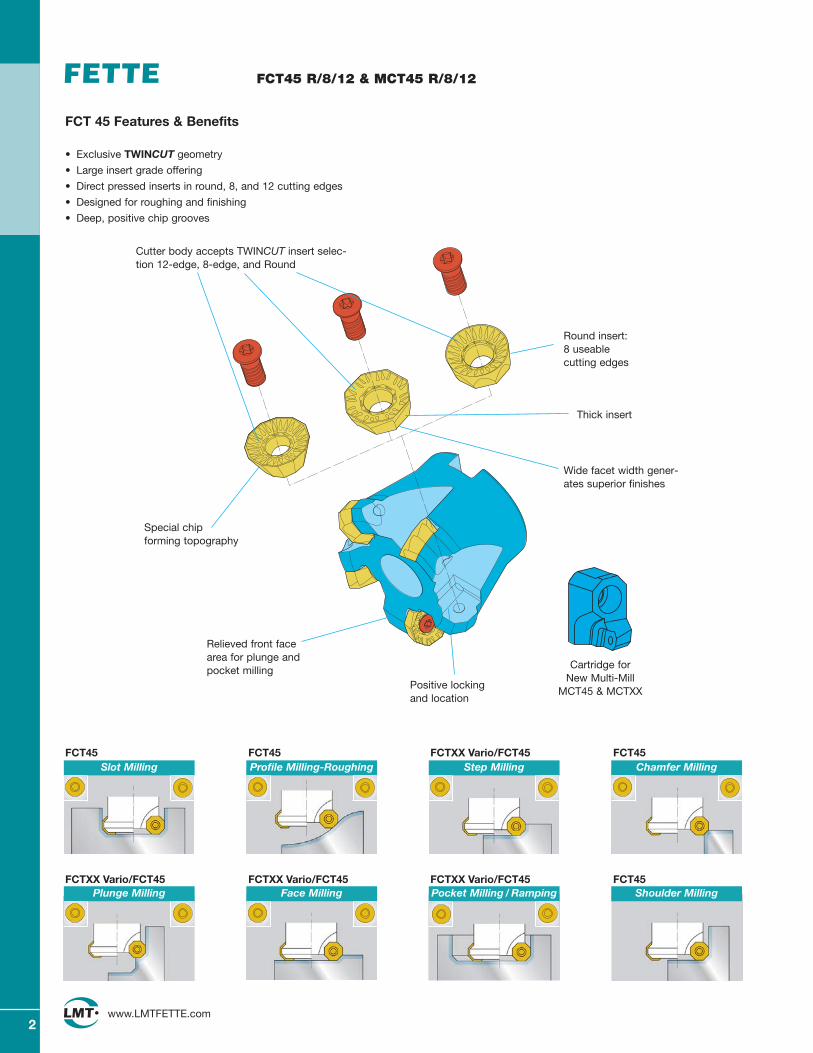
FCT 45 Features & Benefits
• Exclusive TWINCUT geometry
• Large insert grade offering
• Direct pressed inserts in round, 8, and 12 cutting edges
• Designed for roughing and finishing
• Deep, positive chip grooves
Slot Milling Profile Milling-Roughing Step Milling Chamfer Milling
Plunge Milling Face Milling Pocket Milling / Ramping Shoulder Milling
Wide facet width gener-ates superior finishes
Positive lockingand location
Relieved front facearea for plunge andpocket milling
Round insert: 8 useable cutting edges
Special chipforming topography
Thick insert
Cutter body accepts TWINCUT insert selec-tion 12-edge, 8-edge, and Round
Cartridge forNew Multi-Mill
MCT45 & MCTXX
FCT45 FCT45 FCTXX Vario/FCT45 FCT45
FCTXX Vario/FCT45 FCTXX Vario/FCT45 FCTXX Vario/FCT45 FCT45
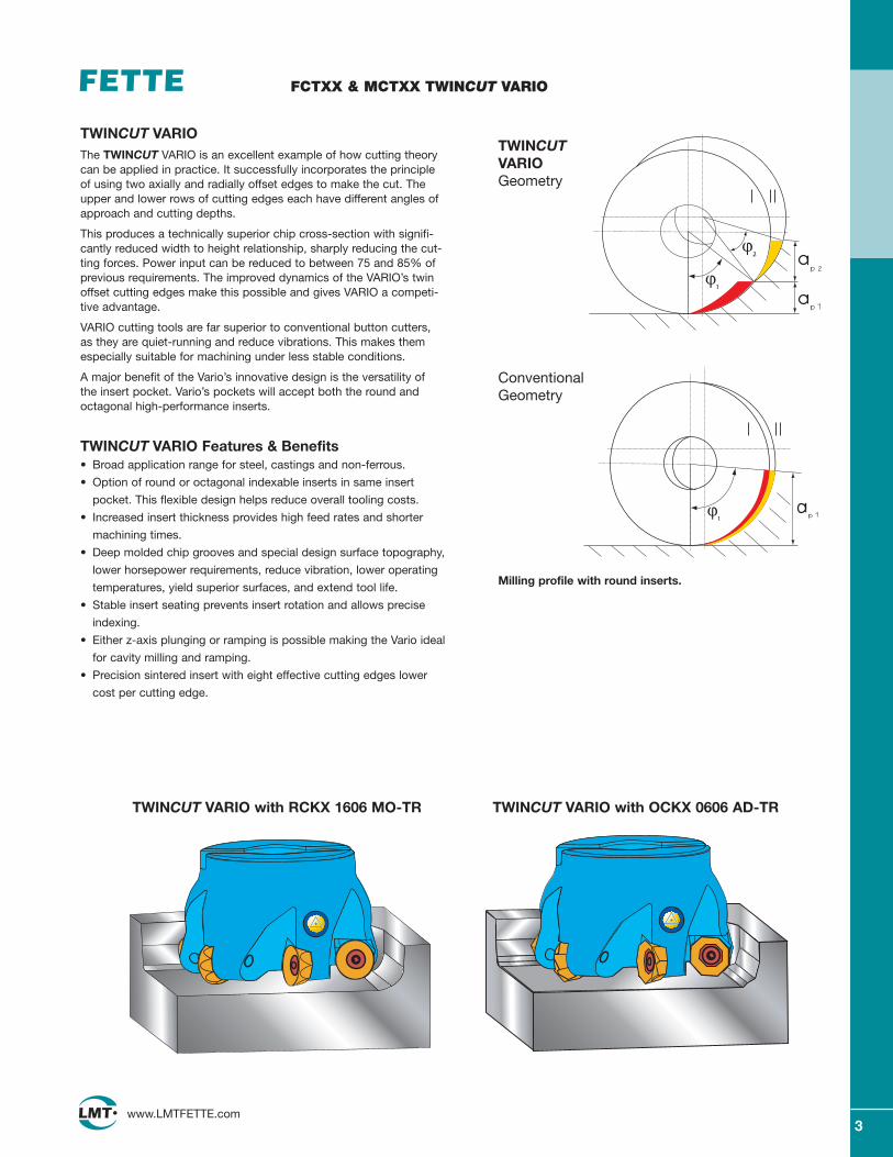
TWINCUT VARIOThe TWINCUT VARIO is an excellent example of how cutting theorycan be applied in practice. It successfully incorporates the principleof using two axially and radially offset edges to make the cut. Theupper and lower rows of cutting edges each have different angles ofapproach and cutting depths.
This produces a technically superior chip cross-section with signifi-cantly reduced width to height relationship, sharply reducing the cut-ting forces. Power input can be reduced to between 75 and 85% ofprevious requirements. The improved dynamics of the VARIO’s twinoffset cutting edges make this possible and gives VARIO a competi-tive advantage.
VARIO cutting tools are far superior to conventional button cutters, as they are quiet-running and reduce vibrations. This makes themespecially suitable for machining under less stable conditions.
A major benefit of the Vario’s innovative design is the versatility of the insert pocket. Vario’s pockets will accept both the round andoctagonal high-performance inserts.
TWINCUT VARIO Features & Benefits• Broad application range for steel, castings and non-ferrous.
• Option of round or octagonal indexable inserts in same insert
pocket. This flexible design helps reduce overall tooling costs.
• Increased insert thickness provides high feed rates and shorter
machining times.
• Deep molded chip grooves and special design surface topography,
lower horsepower requirements, reduce vibration, lower operating
temperatures, yield superior surfaces, and extend tool life.
• Stable insert seating prevents insert rotation and allows precise
indexing.
• Either z-axis plunging or ramping is possible making the Vario ideal
for cavity milling and ramping.
• Precision sintered insert with eight effective cutting edges lower
cost per cutting edge.
Milling profile with round inserts.
TWINCUTVARIOGeometry
ConventionalGeometry
3www.LMTFETTE.com
FCTXX & MCTXX TWINCUT VARIO
TWINCUT VARIO with OCKX 0606 AD-TRTWINCUT VARIO with RCKX 1606 MO-TR
4www.LMTFETTE.com
45° TWINCUT Face Mills
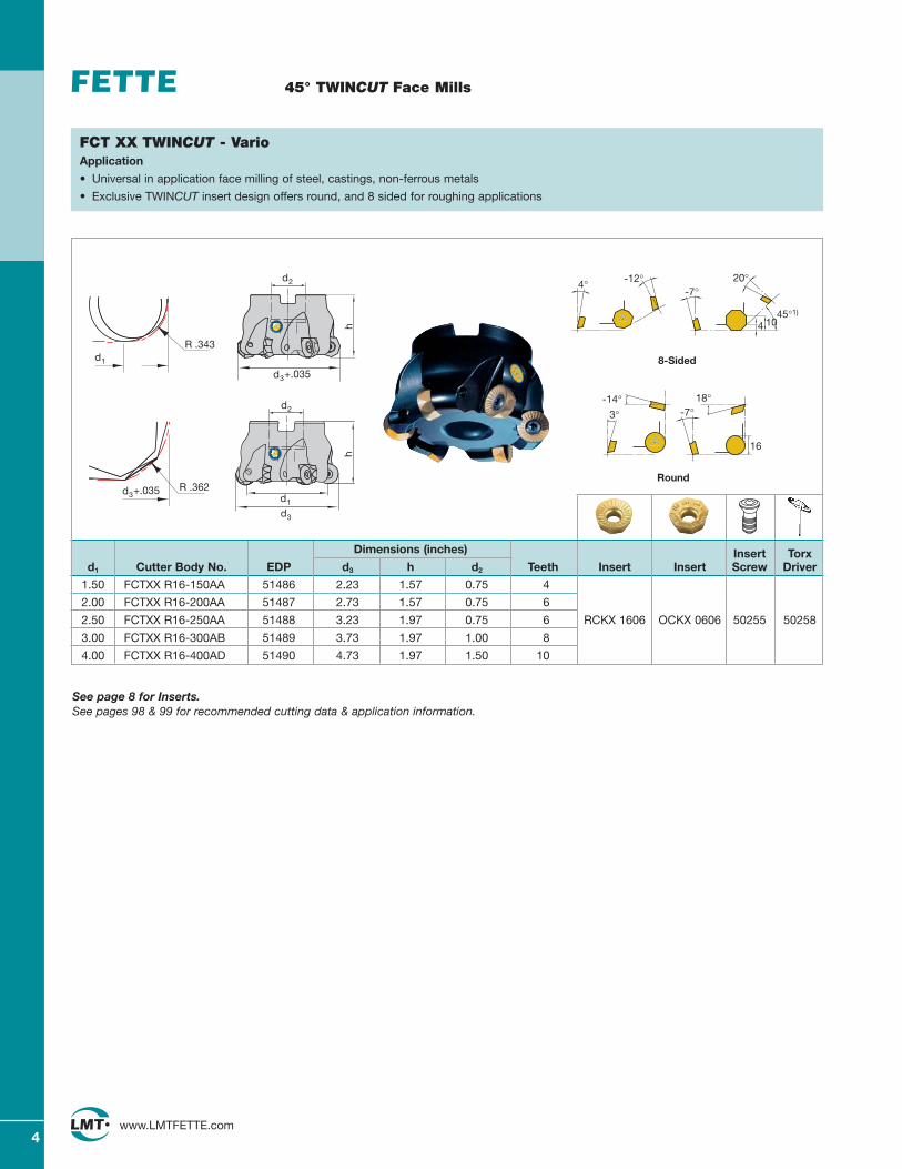
FCT XX TWINCUT - VarioApplication
• Universal in application face milling of steel, castings, non-ferrous metals
• Exclusive TWINCUT insert design offers round, and 8 sided for roughing applications
-7°-12°4° 20°
45°1)
4 10
8-Sided
d2
d3+.035
h
-7°-14°
3°18°
16
Round
d3
h
d1
d2
d1
R .343
d3+.035 R .362
Dimensions (inches) Insert Torxd1 Cutter Body No. EDP d3 h d2 Teeth Insert Insert Screw Driver
1.50 FCTXX R16-150AA 51486 2.23 1.57 0.75 4
2.00 FCTXX R16-200AA 51487 2.73 1.57 0.75 6
2.50 FCTXX R16-250AA 51488 3.23 1.97 0.75 6 RCKX 1606 OCKX 0606 50255 50258
3.00 FCTXX R16-300AB 51489 3.73 1.97 1.00 8
4.00 FCTXX R16-400AD 51490 4.73 1.97 1.50 10
See page 8 for Inserts.See pages 98 & 99 for recommended cutting data & application information.
5www.LMTFETTE.com
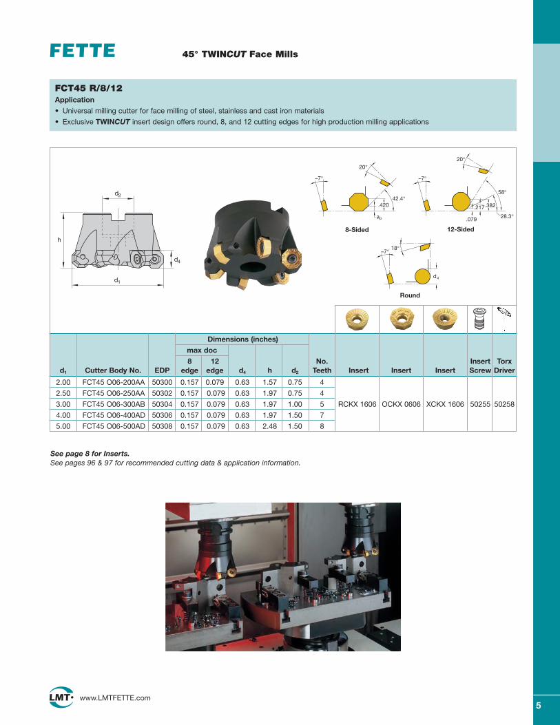
Dimensions (inches)
max doc
8 12 No. Insert Torxd1 Cutter Body No. EDP edge edge d4 h d2 Teeth Insert Insert Insert Screw Driver
2.00 FCT45 O06-200AA 50300 0.157 0.079 0.63 1.57 0.75 4
2.50 FCT45 O06-250AA 50302 0.157 0.079 0.63 1.97 0.75 4
3.00 FCT45 O06-300AB 50304 0.157 0.079 0.63 1.97 1.00 5 RCKX 1606 OCKX 0606 XCKX 1606 50255 50258
4.00 FCT45 O06-400AD 50306 0.157 0.079 0.63 1.97 1.50 7
5.00 FCT45 O06-500AD 50308 0.157 0.079 0.63 2.48 1.50 8
45° TWINCUT Face Mills
FCT45 R/8/12Application
• Universal milling cutter for face milling of steel, stainless and cast iron materials
• Exclusive TWINCUT insert design offers round, 8, and 12 cutting edges for high production milling applications
See page 8 for Inserts.See pages 96 & 97 for recommended cutting data & application information.
20°
ap
42.4°.420
–7°
20°
.217
58°
.079
–7°
.382
28.3°
8-Sided 12-Sided
d1
d2
h
d4
–7°
d4
18°
Round
6www.LMTFETTE.com
45° TWINCUT Face Mills
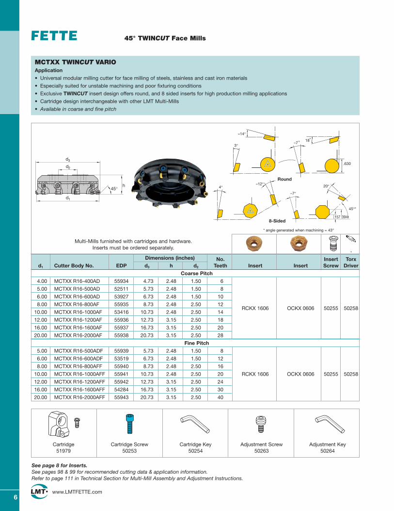
MCTXX TWINCUT VARIOApplication
• Universal modular milling cutter for face milling of steels, stainless and cast iron materials
• Especially suited for unstable machining and poor fixturing conditions
• Exclusive TWINCUT insert design offers round, and 8 sided inserts for high production milling applications
• Cartridge design interchangeable with other LMT Multi-Mills
• Available in coarse and fine pitch
See page 8 for Inserts.See pages 98 & 99 for recommended cutting data & application information.Refer to page 111 in Technical Section for Multi-Mill Assembly and Adjustment Instructions.
Cartridge51979
Cartridge Screw50253
Cartridge Key50254
Adjustment Screw50263
Adjustment Key50264
Multi-Mills furnished with cartridges and hardware. Inserts must be ordered separately.
8-Sided
Dimensions (inches) No. Insert Torxd1 Cutter Body No. EDP d3 h d2 Teeth Insert Insert Screw Driver
Coarse Pitch
4.00 MCTXX R16-400AD 55934 4.73 2.48 1.50 6
5.00 MCTXX R16-500AD 52511 5.73 2.48 1.50 8
6.00 MCTXX R16-600AD 53927 6.73 2.48 1.50 10
8.00 MCTXX R16-800AF 55935 8.73 2.48 2.50 12RCKX 1606 OCKX 0606 50255 50258
10.00 MCTXX R16-1000AF 53416 10.73 2.48 2.50 14
12.00 MCTXX R16-1200AF 55936 12.73 3.15 2.50 18
16.00 MCTXX R16-1600AF 55937 16.73 3.15 2.50 20
20.00 MCTXX R16-2000AF 55938 20.73 3.15 2.50 28
Fine Pitch
5.00 MCTXX R16-500ADF 55939 5.73 2.48 1.50 8
6.00 MCTXX R16-600ADF 53519 6.73 2.48 1.50 12
8.00 MCTXX R16-800AFF 55940 8.73 2.48 2.50 16
10.00 MCTXX R16-1000AFF 55941 10.73 2.48 2.50 20 RCKX 1606 OCKX 0606 50255 50258
12.00 MCTXX R16-1200AFF 55942 12.73 3.15 2.50 24
16.00 MCTXX R16-1600AFF 54284 16.73 3.15 2.50 30
20.00 MCTXX R16-2000AFF 55943 20.73 3.15 2.50 40
–14°
3°
Round
18–7
.630
4°–12°
–7°
20°
45°*
.394.157
* angle generated when machining = 43°
d3
h
d2
d1
45°
7www.LMTFETTE.com
45° TWINCUT Face Mills
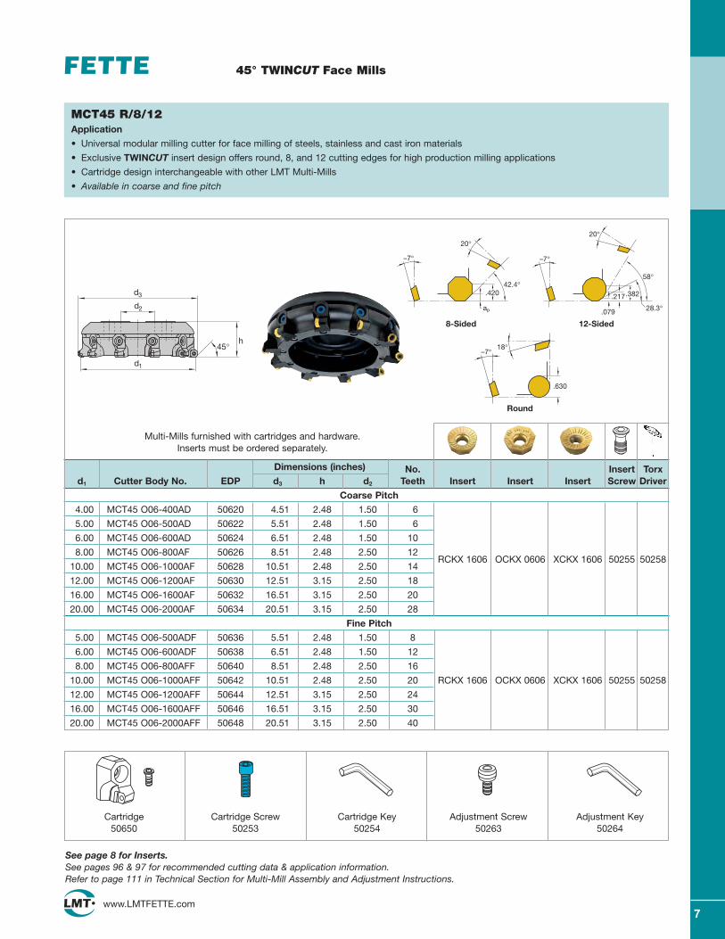
Dimensions (inches) No. Insert Torxd1 Cutter Body No. EDP d3 h d2 Teeth Insert Insert Insert Screw Driver
Coarse Pitch
4.00 MCT45 O06-400AD 50620 4.51 2.48 1.50 6
5.00 MCT45 O06-500AD 50622 5.51 2.48 1.50 6
6.00 MCT45 O06-600AD 50624 6.51 2.48 1.50 10
8.00 MCT45 O06-800AF 50626 8.51 2.48 2.50 12RCKX 1606 OCKX 0606 XCKX 1606 50255 50258
10.00 MCT45 O06-1000AF 50628 10.51 2.48 2.50 14
12.00 MCT45 O06-1200AF 50630 12.51 3.15 2.50 18
16.00 MCT45 O06-1600AF 50632 16.51 3.15 2.50 20
20.00 MCT45 O06-2000AF 50634 20.51 3.15 2.50 28
Fine Pitch
5.00 MCT45 O06-500ADF 50636 5.51 2.48 1.50 8
6.00 MCT45 O06-600ADF 50638 6.51 2.48 1.50 12
8.00 MCT45 O06-800AFF 50640 8.51 2.48 2.50 16
10.00 MCT45 O06-1000AFF 50642 10.51 2.48 2.50 20 RCKX 1606 OCKX 0606 XCKX 1606 50255 50258
12.00 MCT45 O06-1200AFF 50644 12.51 3.15 2.50 24
16.00 MCT45 O06-1600AFF 50646 16.51 3.15 2.50 30
20.00 MCT45 O06-2000AFF 50648 20.51 3.15 2.50 40
MCT45 R/8/12Application
• Universal modular milling cutter for face milling of steels, stainless and cast iron materials
• Exclusive TWINCUT insert design offers round, 8, and 12 cutting edges for high production milling applications
• Cartridge design interchangeable with other LMT Multi-Mills
• Available in coarse and fine pitch
See page 8 for Inserts.See pages 96 & 97 for recommended cutting data & application information.Refer to page 111 in Technical Section for Multi-Mill Assembly and Adjustment Instructions.
Cartridge50650
Cartridge Screw50253
Cartridge Key50254
Adjustment Screw50263
Adjustment Key50264
Multi-Mills furnished with cartridges and hardware. Inserts must be ordered separately.
d3
h
d2
d1
45°
20°
ap
42.4°.420
–7°
8-Sided
20°
.217
58°
.079
–7°
.382
28.3°
12-Sided
–7°
.630
18°
Round
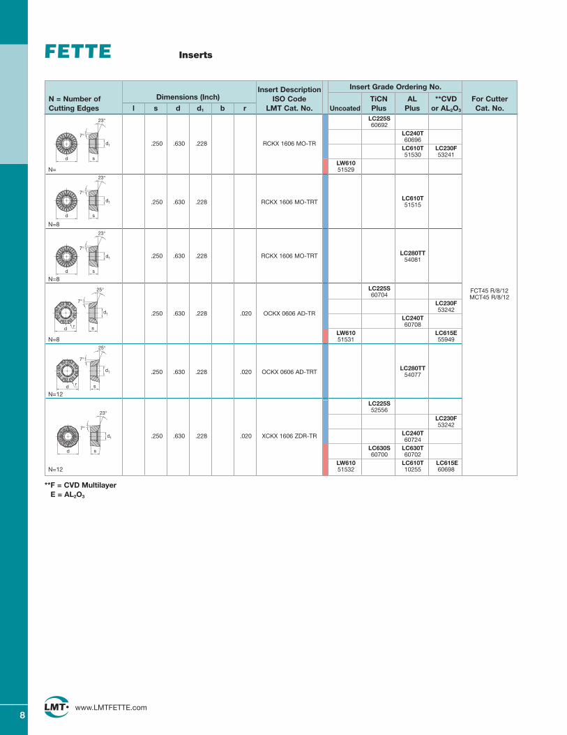
Insert Description Insert Grade Ordering No.
N = Number of Dimensions (Inch) ISO Code TiCN AL **CVD For CutterCutting Edges l s d d1 b r LMT Cat. No. Uncoated Plus Plus or AL2O3 Cat. No.
8www.LMTFETTE.com
Inserts
d s
d1
7°
23°
d s
d1
7°
23°
FCT45 R/8/12MCT45 R/8/12
LC225S60692
LC240T
.250 .630 .228 RCKX 1606 MO-TR60696
LC610T LC230F51530 53241
LW610N= 51529
.250 .630 .228 RCKX 1606 MO-TRTLC610T51515
N=8
.250 .630 .228 RCKX 1606 MO-TRT LC280TT54081
N=8
LC225S60704
LC230F
.250 .630 .228 .020 OCKX 0606 AD-TR53242
LC240T60708
LW610 LC615EN=8 51531 55949
LC280TT.250 .630 .228 .020 OCKX 0606 AD-TRT 54077
N=12
LC225S52556
LC230F53242
.250 .630 .228 .020 XCKX 1606 ZDR-TR LC240T60724
LC630S LC630T60700 60702
LW610 LC610T LC615EN=12 51532 10255 60698
d s
d1
7°
23°
r
7°
sd
d1
25°
r
7°
sd
d1
25°
d s
d1
7°
23°
**F = CVD MultilayerE = AL2O3
9www.LMTFETTE.com
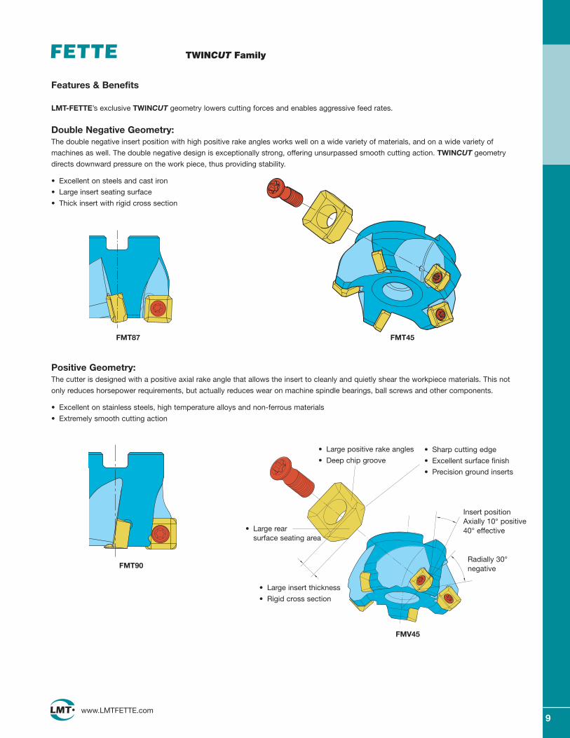
TWINCUT Family
Features & Benefits
LMT-FETTE’s exclusive TWINCUT geometry lowers cutting forces and enables aggressive feed rates.
Double Negative Geometry:The double negative insert position with high positive rake angles works well on a wide variety of materials, and on a wide variety of
machines as well. The double negative design is exceptionally strong, offering unsurpassed smooth cutting action. TWINCUT geometry
directs downward pressure on the work piece, thus providing stability.
• Excellent on steels and cast iron
• Large insert seating surface
• Thick insert with rigid cross section
Positive Geometry:The cutter is designed with a positive axial rake angle that allows the insert to cleanly and quietly shear the workpiece materials. This not
only reduces horsepower requirements, but actually reduces wear on machine spindle bearings, ball screws and other components.
• Excellent on stainless steels, high temperature alloys and non-ferrous materials
• Extremely smooth cutting action
• Large positive rake angles
• Deep chip groove
Radially 30°negative
Insert positionAxially 10° positive40° effective
• Large insert thickness
• Rigid cross section
• Large rear surface seating area
• Sharp cutting edge
• Excellent surface finish
• Precision ground inserts
FMT87 FMT45
FMT90
FMV45
10www.LMTFETTE.com
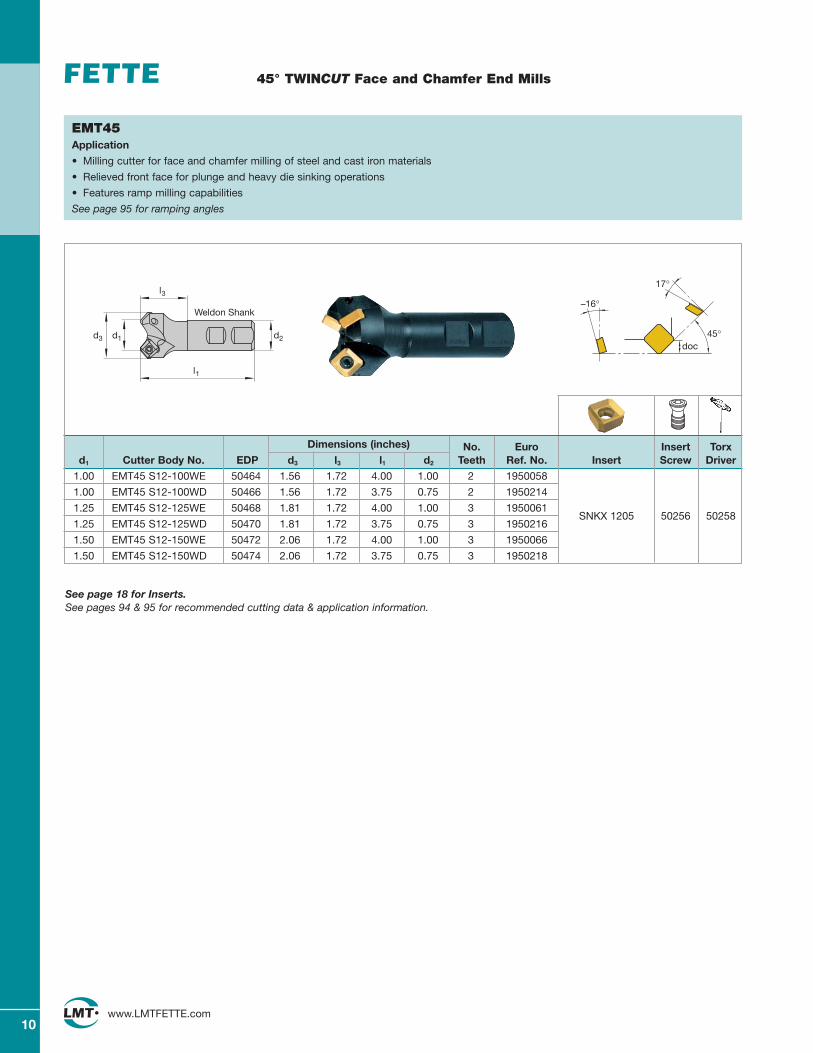
45° TWINCUT Face and Chamfer End Mills
Dimensions (inches) No. Euro Insert Torxd1 Cutter Body No. EDP d3 l3 l1 d2 Teeth Ref. No. Insert Screw Driver
1.00 EMT45 S12-100WE 50464 1.56 1.72 4.00 1.00 2 1950058
1.00 EMT45 S12-100WD 50466 1.56 1.72 3.75 0.75 2 1950214
1.25 EMT45 S12-125WE 50468 1.81 1.72 4.00 1.00 3 1950061SNKX 1205
1.25 EMT45 S12-125WD 50470 1.81 1.72 3.75 0.75 3 195021650256 50258
1.50 EMT45 S12-150WE 50472 2.06 1.72 4.00 1.00 3 1950066
1.50 EMT45 S12-150WD 50474 2.06 1.72 3.75 0.75 3 1950218
EMT45Application
• Milling cutter for face and chamfer milling of steel and cast iron materials
• Relieved front face for plunge and heavy die sinking operations
• Features ramp milling capabilities
See page 95 for ramping angles
d2
l3
l1
d1d3
Weldon Shank
45°doc
–16°
17°
See page 18 for Inserts.See pages 94 & 95 for recommended cutting data & application information.
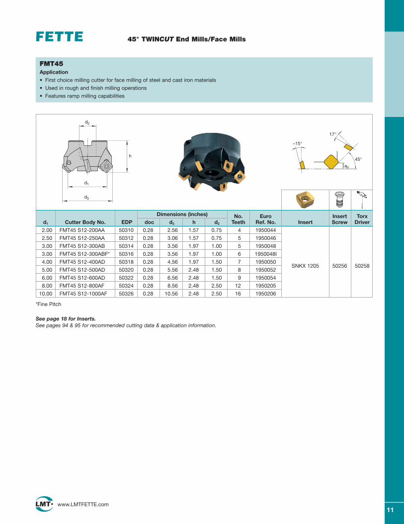
Dimensions (inches) No. Euro Insert Torxd1 Cutter Body No. EDP doc d3 h d2 Teeth Ref. No. Insert Screw Driver
2.00 FMT45 S12-200AA 50310 0.28 2.56 1.57 0.75 4 1950044
2.50 FMT45 S12-250AA 50312 0.28 3.06 1.57 0.75 5 1950046
3.00 FMT45 S12-300AB 50314 0.28 3.56 1.97 1.00 5 1950048
3.00 FMT45 S12-300ABF* 50316 0.28 3.56 1.97 1.00 6 1950048I
4.00 FMT45 S12-400AD 50318 0.28 4.56 1.97 1.50 7 1950050SNKX 1205 50256 50258
5.00 FMT45 S12-500AD 50320 0.28 5.56 2.48 1.50 8 1950052
6.00 FMT45 S12-600AD 50322 0.28 6.56 2.48 1.50 9 1950054
8.00 FMT45 S12-800AF 50324 0.28 8.56 2.48 2.50 12 1950205
10.00 FMT45 S12-1000AF 50326 0.28 10.56 2.48 2.50 16 1950206
45° TWINCUT End Mills/Face Mills
*Fine Pitch
See page 18 for Inserts.See pages 94 & 95 for recommended cutting data & application information.
FMT45 Application
• First choice milling cutter for face milling of steel and cast iron materials
• Used in rough and finish milling operations
• Features ramp milling capabilities
d2
d1
d3
h45°
ap
–15°
17°
11www.LMTFETTE.com

12www.LMTFETTE.com
45° TWINCUT Face Mills
EDP Dimensions (inches) No. Insert Torxd1 Cutter Body No. No. doc d3 h d2 Teeth Insert Screw Driver
Coarse Pitch
4.00 MMT45 S12-400AD 50061 0.280 4.55 2.48 1.50 6
5.00 MMT45 S12-500AD 50062 0.280 5.55 2.48 1.50 6
6.00 MMT45 S12-600AD 50063 0.280 6.55 2.48 1.50 10 SNKX 1205
8.00 MMT45 S12-800AF 50064 0.280 8.55 2.48 2.50 1250256 50258
10.00 MMT45 S12-1000AF 50065 0.280 10.55 2.48 2.50 14 1187-9012.00 MMT45 S12-1200AF 50066 0.280 12.55 3.15 2.50 18 Wiper
16.00 MMT45 S12-1600AF 50067 0.280 16.55 3.15 2.50 20
20.00 MMT45 S12-2000AF 50068 0.280 20.55 3.15 2.50 28
Fine Pitch
5.00 MMT45 S12-500ADF 50069 0.280 5.55 2.48 1.50 8
6.00 MMT45 S12-600ADF 50070 0.280 6.55 2.48 1.50 12 SNKX 1205
8.00 MMT45 S12-800AFF 50071 0.280 8.55 2.48 2.50 16
10.00 MMT45 S12-1000AFF 50072 0.280 10.55 2.48 2.50 20 50256 50258
12.00 MMT45 S12-1200AFF 50073 0.280 12.55 3.15 2.50 24 1187-90
16.00 MMT45 S12-1600AFF 50074 0.280 16.55 3.15 2.50 30 Wiper
20.00 MMT45 S12-2000AFF 50075 0.280 20.55 3.15 2.50 40
45°doc
–15°
17°
MMT45Application
• First choice modular milling cutter for face milling of steel and cast iron materials
• Used in rough and finish milling operations
• Cartridge design interchangeable with other LMT Multi-Mills
• Available in coarse and fine pitch
Cartridge SNKX 120550241
Cartridge Screw50253
Cartridge Key50254
Adjustment Screw50263
Adjustment Key50264
See page 18 for Inserts.See pages 94 & 95 for recommended cutting data & application information. Refer to page 111 in technical section for Multi-Mill assembly and adjustment instructions.
Multi-Mills furnished with cartridges and hardware. Inserts must be ordered separately.
h
d1
45°
d2
d3
13www.LMTFETTE.com
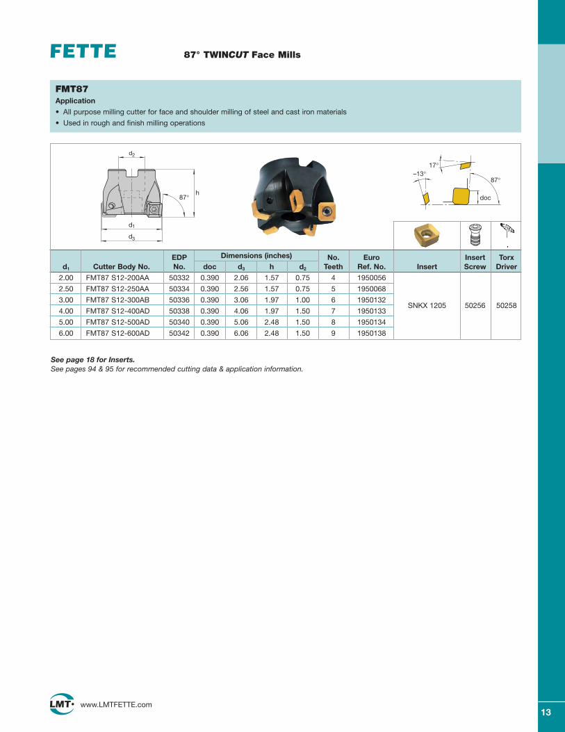
87° TWINCUT Face Mills
EDP Dimensions (inches) No. Euro Insert Torxd1 Cutter Body No. No. doc d3 h d2 Teeth Ref. No. Insert Screw Driver
2.00 FMT87 S12-200AA 50332 0.390 2.06 1.57 0.75 4 1950056
2.50 FMT87 S12-250AA 50334 0.390 2.56 1.57 0.75 5 1950068
3.00 FMT87 S12-300AB 50336 0.390 3.06 1.97 1.00 6 1950132SNKX 1205 50256 50258
4.00 FMT87 S12-400AD 50338 0.390 4.06 1.97 1.50 7 1950133
5.00 FMT87 S12-500AD 50340 0.390 5.06 2.48 1.50 8 1950134
6.00 FMT87 S12-600AD 50342 0.390 6.06 2.48 1.50 9 1950138
87°
doc
–13°17°
FMT87Application
• All purpose milling cutter for face and shoulder milling of steel and cast iron materials
• Used in rough and finish milling operations
See page 18 for Inserts.See pages 94 & 95 for recommended cutting data & application information.
d2
d3
h87°
d1
14www.LMTFETTE.com
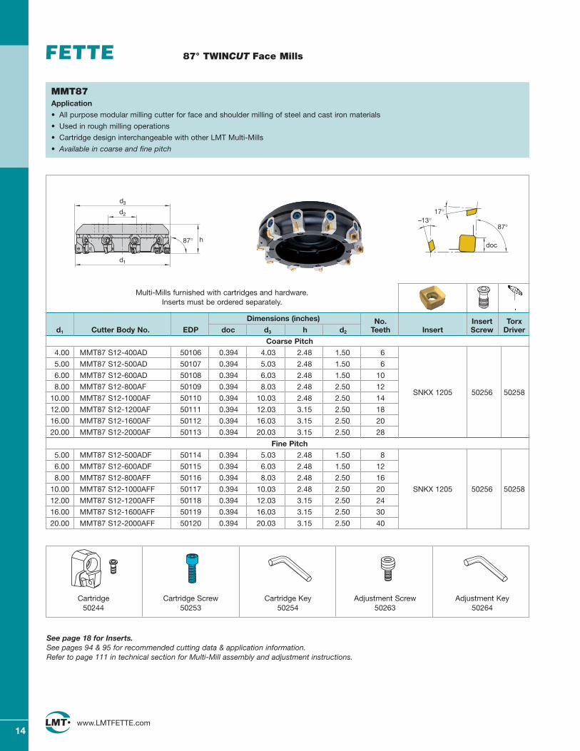
87° TWINCUT Face Mills
Dimensions (inches) No. Insert Torxd1 Cutter Body No. EDP doc d3 h d2 Teeth Insert Screw Driver
Coarse Pitch
4.00 MMT87 S12-400AD 50106 0.394 4.03 2.48 1.50 6
5.00 MMT87 S12-500AD 50107 0.394 5.03 2.48 1.50 6
6.00 MMT87 S12-600AD 50108 0.394 6.03 2.48 1.50 10
8.00 MMT87 S12-800AF 50109 0.394 8.03 2.48 2.50 12SNKX 1205 50256 50258
10.00 MMT87 S12-1000AF 50110 0.394 10.03 2.48 2.50 14
12.00 MMT87 S12-1200AF 50111 0.394 12.03 3.15 2.50 18
16.00 MMT87 S12-1600AF 50112 0.394 16.03 3.15 2.50 20
20.00 MMT87 S12-2000AF 50113 0.394 20.03 3.15 2.50 28
Fine Pitch
5.00 MMT87 S12-500ADF 50114 0.394 5.03 2.48 1.50 8
6.00 MMT87 S12-600ADF 50115 0.394 6.03 2.48 1.50 12
8.00 MMT87 S12-800AFF 50116 0.394 8.03 2.48 2.50 16
10.00 MMT87 S12-1000AFF 50117 0.394 10.03 2.48 2.50 20 SNKX 1205 50256 50258
12.00 MMT87 S12-1200AFF 50118 0.394 12.03 3.15 2.50 24
16.00 MMT87 S12-1600AFF 50119 0.394 16.03 3.15 2.50 30
20.00 MMT87 S12-2000AFF 50120 0.394 20.03 3.15 2.50 40
87°
doc
–13°17°
MMT87Application
• All purpose modular milling cutter for face and shoulder milling of steel and cast iron materials
• Used in rough milling operations
• Cartridge design interchangeable with other LMT Multi-Mills
• Available in coarse and fine pitch
Cartridge50244
Cartridge Screw50253
Cartridge Key50254
Adjustment Screw50263
Adjustment Key50264
See page 18 for Inserts.See pages 94 & 95 for recommended cutting data & application information. Refer to page 111 in technical section for Multi-Mill assembly and adjustment instructions.
Multi-Mills furnished with cartridges and hardware. Inserts must be ordered separately.
h
d1
87°
d2
d3
15www.LMTFETTE.com
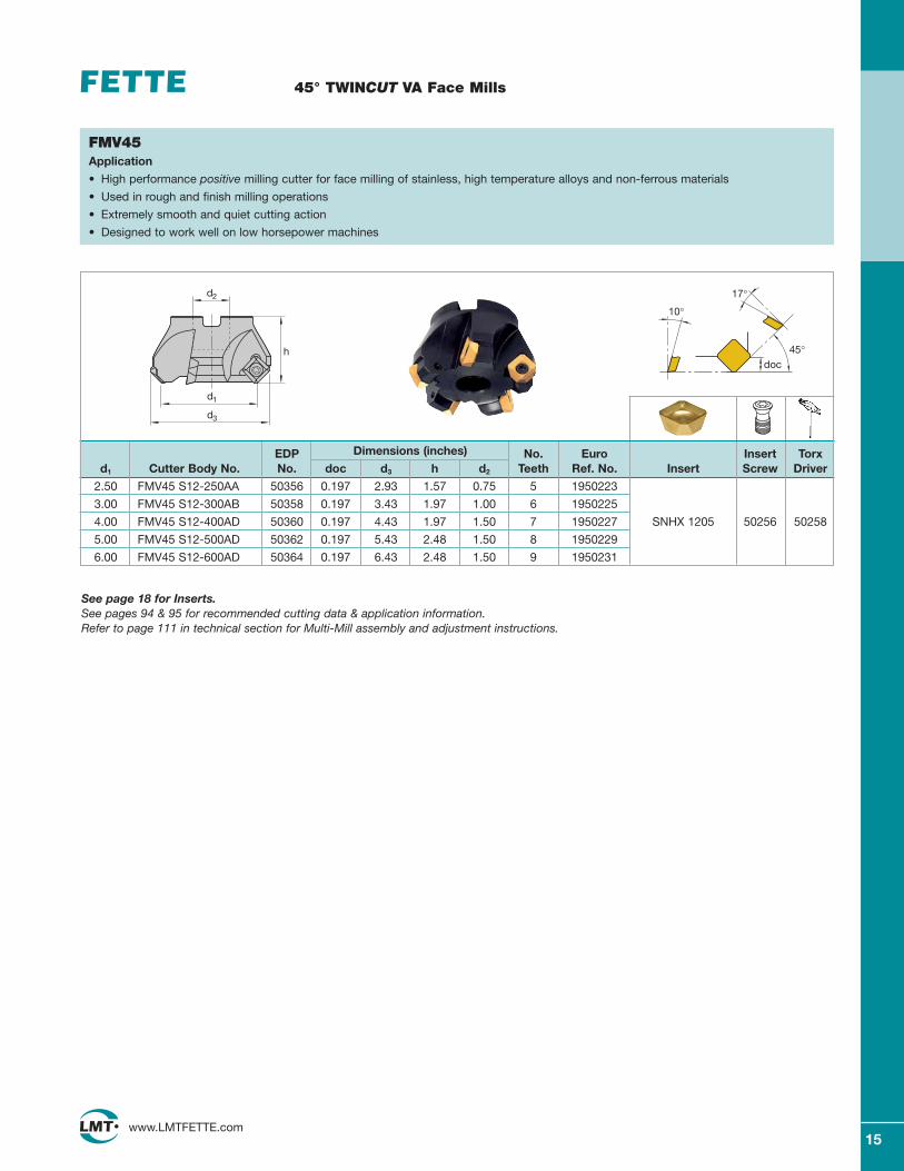
45° TWINCUT VA Face Mills
EDP Dimensions (inches) No. Euro Insert Torxd1 Cutter Body No. No. doc d3 h d2 Teeth Ref. No. Insert Screw Driver
2.50 FMV45 S12-250AA 50356 0.197 2.93 1.57 0.75 5 1950223
3.00 FMV45 S12-300AB 50358 0.197 3.43 1.97 1.00 6 1950225
4.00 FMV45 S12-400AD 50360 0.197 4.43 1.97 1.50 7 1950227 SNHX 1205 50256 50258
5.00 FMV45 S12-500AD 50362 0.197 5.43 2.48 1.50 8 1950229
6.00 FMV45 S12-600AD 50364 0.197 6.43 2.48 1.50 9 1950231
17°
10°
doc45°
FMV45Application
• High performance positive milling cutter for face milling of stainless, high temperature alloys and non-ferrous materials
• Used in rough and finish milling operations
• Extremely smooth and quiet cutting action
• Designed to work well on low horsepower machines
d2
d1
d3
h
See page 18 for Inserts.See pages 94 & 95 for recommended cutting data & application information. Refer to page 111 in technical section for Multi-Mill assembly and adjustment instructions.
16www.LMTFETTE.com
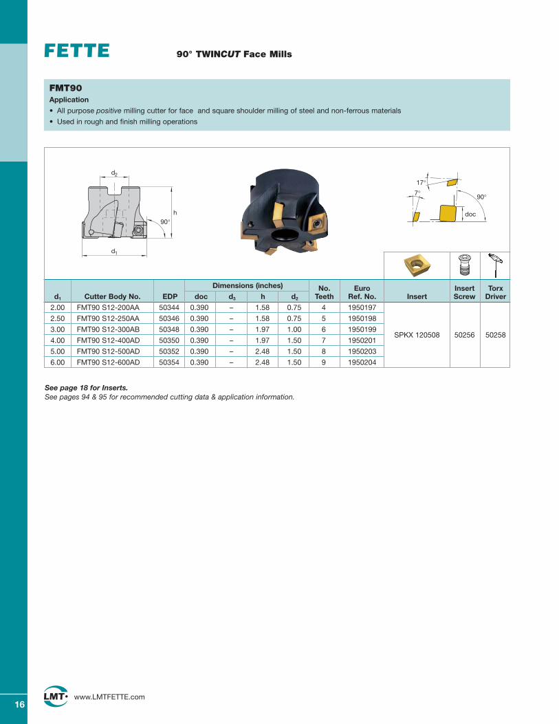
90° TWINCUT Face Mills
FMT90Application
• All purpose positive milling cutter for face and square shoulder milling of steel and non-ferrous materials
• Used in rough and finish milling operations
Dimensions (inches) No. Euro Insert Torxd1 Cutter Body No. EDP doc d3 h d2 Teeth Ref. No. Insert Screw Driver
2.00 FMT90 S12-200AA 50344 0.390 – 1.58 0.75 4 1950197
2.50 FMT90 S12-250AA 50346 0.390 – 1.58 0.75 5 1950198
3.00 FMT90 S12-300AB 50348 0.390 – 1.97 1.00 6 1950199SPKX 120508 50256 50258
4.00 FMT90 S12-400AD 50350 0.390 – 1.97 1.50 7 1950201
5.00 FMT90 S12-500AD 50352 0.390 – 2.48 1.50 8 1950203
6.00 FMT90 S12-600AD 50354 0.390 – 2.48 1.50 9 1950204
7°17°
90°
doc
See page 18 for Inserts.See pages 94 & 95 for recommended cutting data & application information.
90°
d1
d2
h
17www.LMTFETTE.com
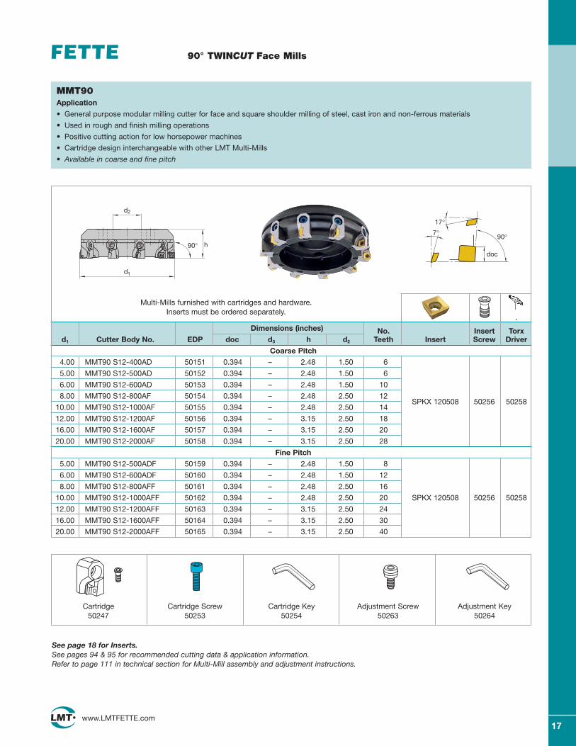
90° TWINCUT Face Mills
MMT90Application
• General purpose modular milling cutter for face and square shoulder milling of steel, cast iron and non-ferrous materials
• Used in rough and finish milling operations
• Positive cutting action for low horsepower machines
• Cartridge design interchangeable with other LMT Multi-Mills
• Available in coarse and fine pitch
Dimensions (inches) No. Insert Torxd1 Cutter Body No. EDP doc d3 h d2 Teeth Insert Screw Driver
Coarse Pitch
4.00 MMT90 S12-400AD 50151 0.394 – 2.48 1.50 6
5.00 MMT90 S12-500AD 50152 0.394 – 2.48 1.50 6
6.00 MMT90 S12-600AD 50153 0.394 – 2.48 1.50 10
8.00 MMT90 S12-800AF 50154 0.394 – 2.48 2.50 12SPKX 120508 50256 50258
10.00 MMT90 S12-1000AF 50155 0.394 – 2.48 2.50 14
12.00 MMT90 S12-1200AF 50156 0.394 – 3.15 2.50 18
16.00 MMT90 S12-1600AF 50157 0.394 – 3.15 2.50 20
20.00 MMT90 S12-2000AF 50158 0.394 – 3.15 2.50 28
Fine Pitch
5.00 MMT90 S12-500ADF 50159 0.394 – 2.48 1.50 8
6.00 MMT90 S12-600ADF 50160 0.394 – 2.48 1.50 12
8.00 MMT90 S12-800AFF 50161 0.394 – 2.48 2.50 16
10.00 MMT90 S12-1000AFF 50162 0.394 – 2.48 2.50 20 SPKX 120508 50256 50258
12.00 MMT90 S12-1200AFF 50163 0.394 – 3.15 2.50 24
16.00 MMT90 S12-1600AFF 50164 0.394 – 3.15 2.50 30
20.00 MMT90 S12-2000AFF 50165 0.394 – 3.15 2.50 40
7°17°
90°
doc
Multi-Mills furnished with cartridges and hardware. Inserts must be ordered separately.
See page 18 for Inserts.See pages 94 & 95 for recommended cutting data & application information. Refer to page 111 in technical section for Multi-Mill assembly and adjustment instructions.
Cartridge50247
Cartridge Screw50253
Cartridge Key50254
Adjustment Screw50263
Adjustment Key50264
h
d1
90°
d2
LC225S60045
.500 .219 .205 .078 SNKX 1205 AN-TR LC240T1187-10 TR 60047
LC610T60048
N=4
LC225S60036
LC230F.500 .219 .205 .078 SNKX 1205 AN 53791
1187-10 LC240T60039
LW610 LC610T LC615EN=4 60035 89936 55955
LC225S
SNKX 1205 AN-T60050
.500 .219 .205 .078 1187-12 LC240TT-Land 60053
LC610T60054
N=4
.500 .219 .205 .078 SNKX 1205 AN-TT LC280TTT-Land 54089
N=4
LC240T.500 .219 .205 .078 SNKQ 1205 AN 50735
1187-13 LW610 LC610T LC615E60055 51953 55954
N=8
.750 .219 .500 .205 1187-90 LC225SWiper Insert 60058
N=1
LC225S60091
LC240T.500 .219 .205 .032 SPKX 120508 60093
1187-15 LC230F53797
LW610 LC615EN=4 60090 60726
LC225S LC230F.500 .219 .205 .086 SNHX 1205 AE 60340 53787
1187-18 LC440T 50948
N=4
.500 .219 .205 .078 SNHT 1205 AEFN-ALC LC610T•
1187-18 ALC 89221
N=4
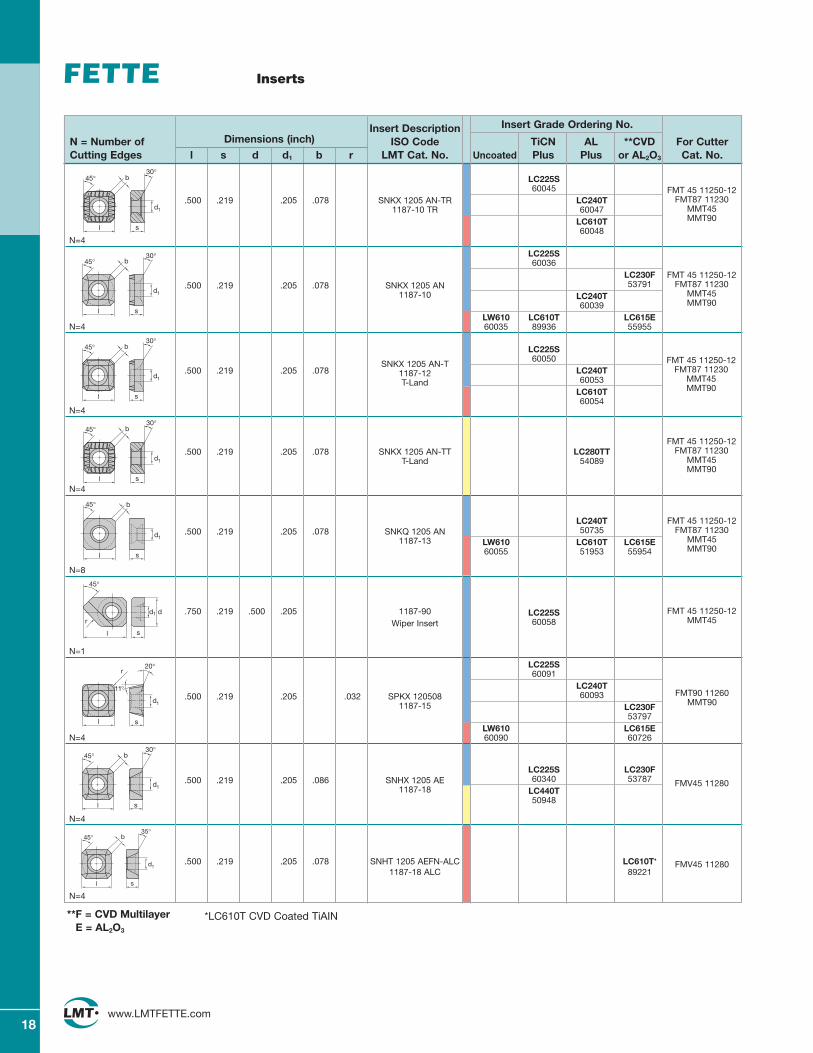
18www.LMTFETTE.com
Inserts
Insert Description Insert Grade Ordering No.
N = Number of Dimensions (inch) ISO Code TiCN AL **CVD For CutterCutting Edges l s d d1 b r LMT Cat. No. Uncoated Plus Plus or AL2O3 Cat. No.
b
s
d1
30°
l
45°
b
l s
d1
30°45°
b
s
d1
30°45°
l
b
s
d1
30°
l
45°
sl
45° b
d1
b
s
d1
30°45°
l
b
s
d1
35°45°
l
FMT 45 11250-12FMT87 11230
MMT45MMT90
FMT 45 11250-12FMT87 11230
MMT45MMT90
FMT 45 11250-12FMT87 11230
MMT45MMT90
FMT 45 11250-12FMT87 11230
MMT45MMT90
FMT 45 11250-12MMT45
FMT90 11260MMT90
FMV45 11280
FMV45 11280
FMT 45 11250-12FMT87 11230
MMT45MMT90
*LC610T CVD Coated TiAIN**F = CVD MultilayerE = AL2O3
s
d1
l
dr
45°
s
20°
d1
11°
r
l
19www.LMTFETTE.com
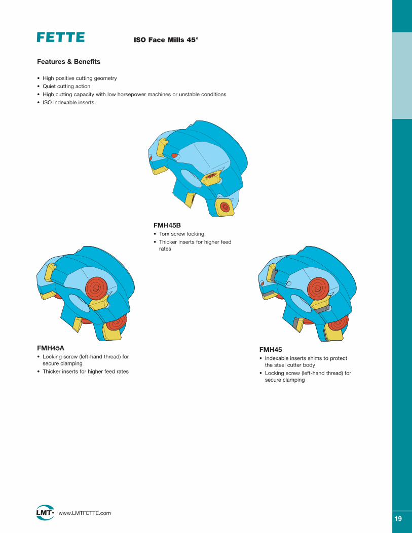
ISO Face Mills 45°
Features & Benefits
• High positive cutting geometry
• Quiet cutting action
• High cutting capacity with low horsepower machines or unstable conditions
• ISO indexable inserts
FMH45A • Locking screw (left-hand thread) for
secure clamping
• Thicker inserts for higher feed rates
FMH45B • Torx screw locking
• Thicker inserts for higher feedrates
FMH45• Indexable inserts shims to protect
the steel cutter body
• Locking screw (left-hand thread) forsecure clamping
20www.LMTFETTE.com
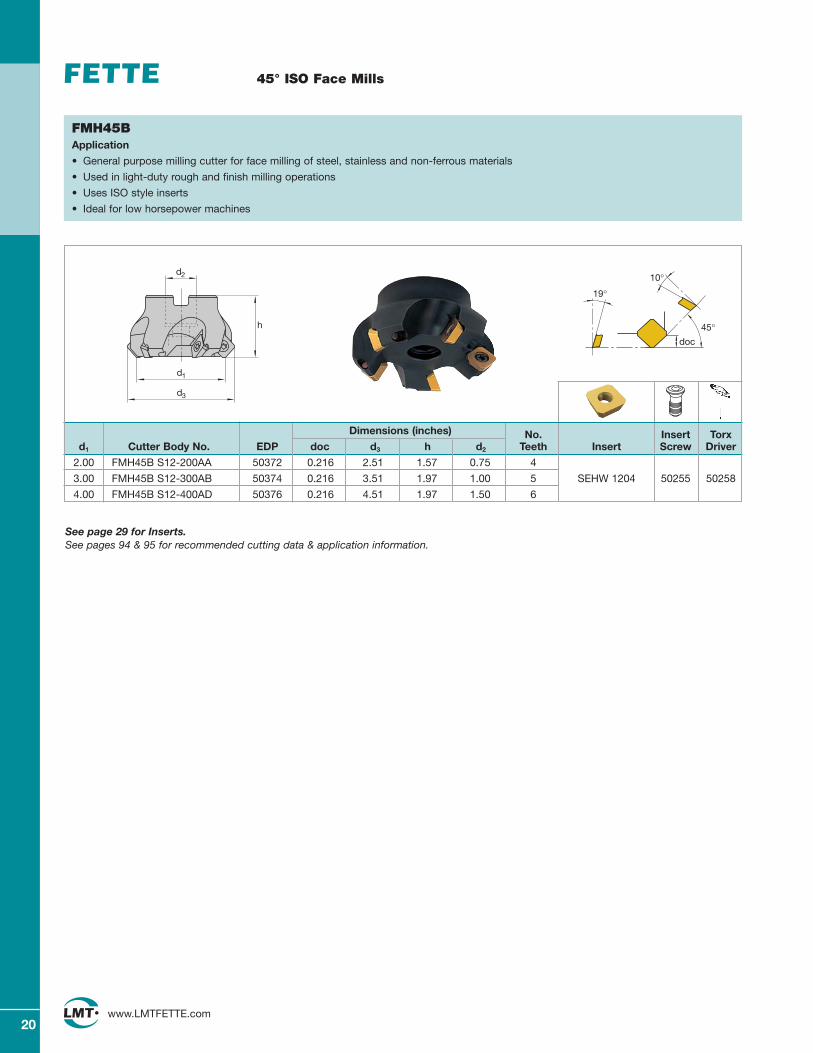
45° ISO Face Mills
Dimensions (inches) No. Insert Torxd1 Cutter Body No. EDP doc d3 h d2 Teeth Insert Screw Driver
2.00 FMH45B S12-200AA 50372 0.216 2.51 1.57 0.75 4
3.00 FMH45B S12-300AB 50374 0.216 3.51 1.97 1.00 5 SEHW 1204 50255 50258
4.00 FMH45B S12-400AD 50376 0.216 4.51 1.97 1.50 6
10°
19°
doc
45°
FMH45BApplication
• General purpose milling cutter for face milling of steel, stainless and non-ferrous materials
• Used in light-duty rough and finish milling operations
• Uses ISO style inserts
• Ideal for low horsepower machines
d2
d1
d3
h
See page 29 for Inserts.See pages 94 & 95 for recommended cutting data & application information.
21www.LMTFETTE.com
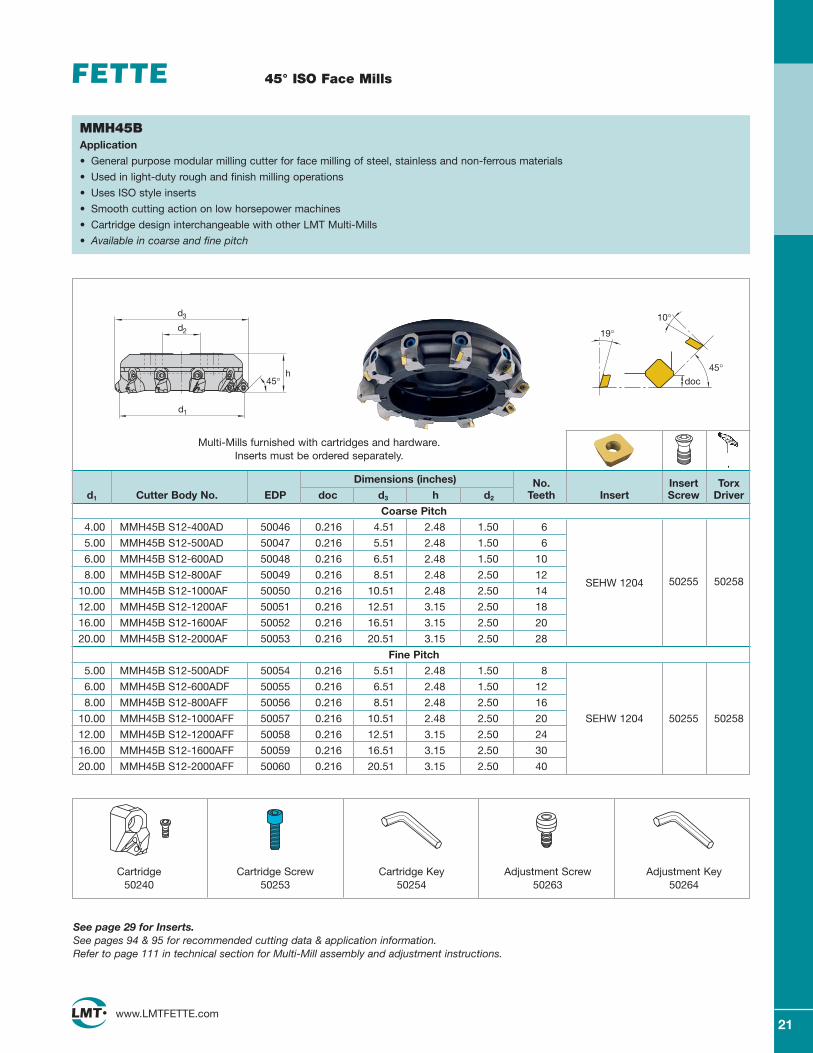
45° ISO Face Mills
Dimensions (inches) No. Insert Torxd1 Cutter Body No. EDP doc d3 h d2 Teeth Insert Screw Driver
Coarse Pitch
4.00 MMH45B S12-400AD 50046 0.216 4.51 2.48 1.50 6
5.00 MMH45B S12-500AD 50047 0.216 5.51 2.48 1.50 6
6.00 MMH45B S12-600AD 50048 0.216 6.51 2.48 1.50 10
8.00 MMH45B S12-800AF 50049 0.216 8.51 2.48 2.50 12SEHW 1204 50255 50258
10.00 MMH45B S12-1000AF 50050 0.216 10.51 2.48 2.50 14
12.00 MMH45B S12-1200AF 50051 0.216 12.51 3.15 2.50 18
16.00 MMH45B S12-1600AF 50052 0.216 16.51 3.15 2.50 20
20.00 MMH45B S12-2000AF 50053 0.216 20.51 3.15 2.50 28
Fine Pitch
5.00 MMH45B S12-500ADF 50054 0.216 5.51 2.48 1.50 8
6.00 MMH45B S12-600ADF 50055 0.216 6.51 2.48 1.50 12
8.00 MMH45B S12-800AFF 50056 0.216 8.51 2.48 2.50 16
10.00 MMH45B S12-1000AFF 50057 0.216 10.51 2.48 2.50 20 SEHW 1204 50255 50258
12.00 MMH45B S12-1200AFF 50058 0.216 12.51 3.15 2.50 24
16.00 MMH45B S12-1600AFF 50059 0.216 16.51 3.15 2.50 30
20.00 MMH45B S12-2000AFF 50060 0.216 20.51 3.15 2.50 40
10°
19°
doc
45°
MMH45BApplication
• General purpose modular milling cutter for face milling of steel, stainless and non-ferrous materials
• Used in light-duty rough and finish milling operations
• Uses ISO style inserts
• Smooth cutting action on low horsepower machines
• Cartridge design interchangeable with other LMT Multi-Mills
• Available in coarse and fine pitch
Cartridge50240
Cartridge Screw50253
Cartridge Key50254
Adjustment Screw50263
Adjustment Key50264
See page 29 for Inserts.See pages 94 & 95 for recommended cutting data & application information. Refer to page 111 in technical section for Multi-Mill assembly and adjustment instructions.
Multi-Mills furnished with cartridges and hardware. Inserts must be ordered separately.
h
d1
45°
d2
d3
22www.LMTFETTE.com
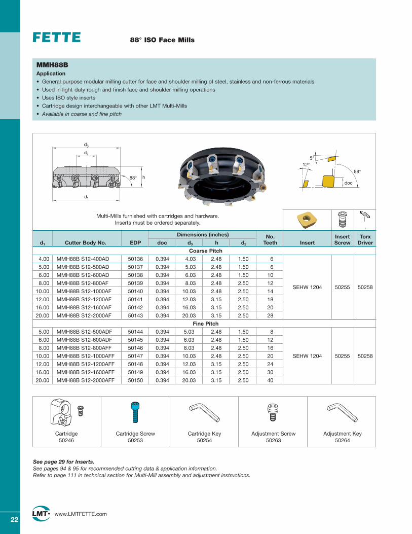
88° ISO Face Mills
Dimensions (inches) No. Insert Torxd1 Cutter Body No. EDP doc d3 h d2 Teeth Insert Screw Driver
Coarse Pitch
4.00 MMH88B S12-400AD 50136 0.394 4.03 2.48 1.50 6
5.00 MMH88B S12-500AD 50137 0.394 5.03 2.48 1.50 6
6.00 MMH88B S12-600AD 50138 0.394 6.03 2.48 1.50 10
8.00 MMH88B S12-800AF 50139 0.394 8.03 2.48 2.50 12SEHW 1204
10.00 MMH88B S12-1000AF 50140 0.394 10.03 2.48 2.50 1450255 50258
12.00 MMH88B S12-1200AF 50141 0.394 12.03 3.15 2.50 18
16.00 MMH88B S12-1600AF 50142 0.394 16.03 3.15 2.50 20
20.00 MMH88B S12-2000AF 50143 0.394 20.03 3.15 2.50 28
Fine Pitch
5.00 MMH88B S12-500ADF 50144 0.394 5.03 2.48 1.50 8
6.00 MMH88B S12-600ADF 50145 0.394 6.03 2.48 1.50 12
8.00 MMH88B S12-800AFF 50146 0.394 8.03 2.48 2.50 16
10.00 MMH88B S12-1000AFF 50147 0.394 10.03 2.48 2.50 20 SEHW 1204 50255 50258
12.00 MMH88B S12-1200AFF 50148 0.394 12.03 3.15 2.50 24
16.00 MMH88B S12-1600AFF 50149 0.394 16.03 3.15 2.50 30
20.00 MMH88B S12-2000AFF 50150 0.394 20.03 3.15 2.50 40
12°
doc
88°
5°
MMH88BApplication
• General purpose modular milling cutter for face and shoulder milling of steel, stainless and non-ferrous materials
• Used in light-duty rough and finish face and shoulder milling operations
• Uses ISO style inserts
• Cartridge design interchangeable with other LMT Multi-Mills
• Available in coarse and fine pitch
Cartridge50246
Cartridge Screw50253
Cartridge Key50254
Adjustment Screw50263
Adjustment Key50264
See page 29 for Inserts.See pages 94 & 95 for recommended cutting data & application information. Refer to page 111 in technical section for Multi-Mill assembly and adjustment instructions.
Multi-Mills furnished with cartridges and hardware. Inserts must be ordered separately.
h
d1
88°
d2
d3
23www.LMTFETTE.com
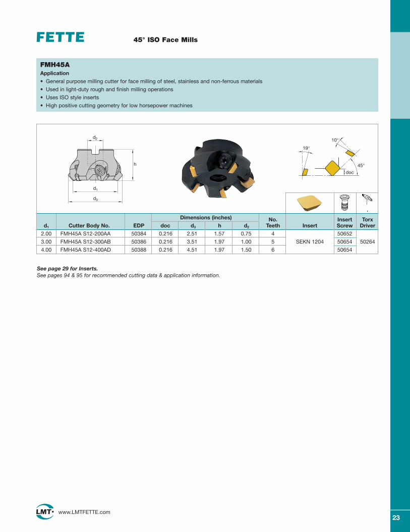
45° ISO Face Mills
Dimensions (inches) No. Insert Torxd1 Cutter Body No. EDP doc d3 h d2 Teeth Insert Screw Driver
2.00 FMH45A S12-200AA 50384 0.216 2.51 1.57 0.75 4 50652
3.00 FMH45A S12-300AB 50386 0.216 3.51 1.97 1.00 5 SEKN 1204 50654 50264
4.00 FMH45A S12-400AD 50388 0.216 4.51 1.97 1.50 6 50654
10°
19°
doc
45°
FMH45AApplication
• General purpose milling cutter for face milling of steel, stainless and non-ferrous materials
• Used in light-duty rough and finish milling operations
• Uses ISO style inserts
• High positive cutting geometry for low horsepower machines
See page 29 for Inserts.See pages 94 & 95 for recommended cutting data & application information.
d2
d1
d3
h
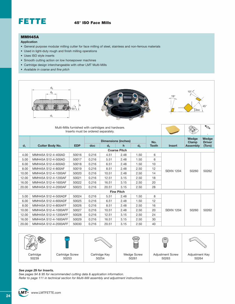
24www.LMTFETTE.com
45° ISO Face Mills
MMH45AApplication
• General purpose modular milling cutter for face milling of steel, stainless and non-ferrous materials
• Used in light-duty rough and finish milling operations
• Uses ISO style inserts
• Smooth cutting action on low horsepower machines
• Cartridge design interchangeable with other LMT Multi-Mills
• Available in coarse and fine pitch
Wedge WedgeDimensions (inches) No. Clamp Driver
d1 Cutter Body No. EDP doc d3 h d2 Teeth Insert Assembly (Torx)
Coarse Pitch
4.00 MMH45A S12-4-400AD 50016 0.216 4.51 2.48 1.50 6
5.00 MMH45A S12-4-500AD 50017 0.216 5.51 2.48 1.50 6
6.00 MMH45A S12-4-600AD 50018 0.216 6.51 2.48 1.50 10
8.00 MMH45A S12-4-800AF 50019 0.216 8.51 2.48 2.50 12SEKN 1204
10.00 MMH45A S12-4-1000AF 50020 0.216 10.51 2.48 2.50 1450260 50262
12.00 MMH45A S12-4-1200AF 50021 0.216 12.51 3.15 2.50 18
16.00 MMH45A S12-4-1600AF 50022 0.216 16.51 3.15 2.50 20
20.00 MMH45A S12-4-2000AF 50023 0.216 20.51 3.15 2.50 28
Fine Pitch
5.00 MMH45A S12-4-500ADF 50024 0.216 5.51 2.48 1.50 8
6.00 MMH45A S12-4-600ADF 50025 0.216 6.51 2.48 1.50 12
8.00 MMH45A S12-4-800AFF 50026 0.216 8.51 2.48 2.50 16
10.00 MMH45A S12-4-1000AFF 50027 0.216 10.51 2.48 2.50 20 SEKN 1204 50260 50262
12.00 MMH45A S12-4-1200AFF 50028 0.216 12.51 3.15 2.50 24
16.00 MMH45A S12-4-1600AFF 50029 0.216 16.51 3.15 2.50 30
20.00 MMH45A S12-4-2000AFF 50030 0.216 20.51 3.15 2.50 40
10°
19°
doc45°
Cartridge50239
Cartridge Screw50253
Cartridge Key50254
Wedge Screw50261
Adjustment Screw50263
Adjustment Key50264
See page 29 for Inserts.See pages 94 & 95 for recommended cutting data & application information. Refer to page 111 in technical section for Multi-Mill assembly and adjustment instructions.
Multi-Mills furnished with cartridges and hardware. Inserts must be ordered separately.
d3
h
d2
d1
45°
25www.LMTFETTE.com
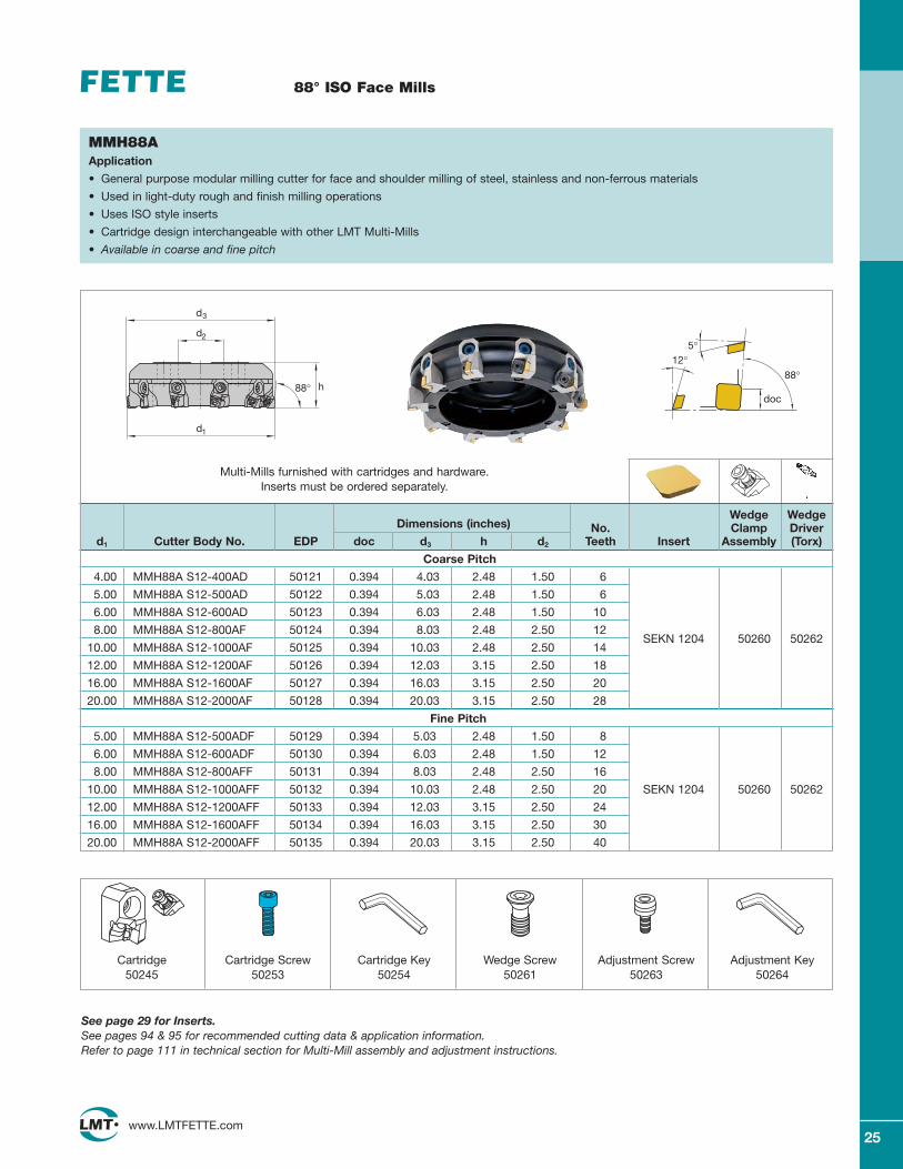
88° ISO Face Mills
MMH88AApplication
• General purpose modular milling cutter for face and shoulder milling of steel, stainless and non-ferrous materials
• Used in light-duty rough and finish milling operations
• Uses ISO style inserts
• Cartridge design interchangeable with other LMT Multi-Mills
• Available in coarse and fine pitch
Wedge WedgeDimensions (inches) No. Clamp Driver
d1 Cutter Body No. EDP doc d3 h d2 Teeth Insert Assembly (Torx)
Coarse Pitch
4.00 MMH88A S12-400AD 50121 0.394 4.03 2.48 1.50 6
5.00 MMH88A S12-500AD 50122 0.394 5.03 2.48 1.50 6
6.00 MMH88A S12-600AD 50123 0.394 6.03 2.48 1.50 10
8.00 MMH88A S12-800AF 50124 0.394 8.03 2.48 2.50 12SEKN 1204
10.00 MMH88A S12-1000AF 50125 0.394 10.03 2.48 2.50 1450260 50262
12.00 MMH88A S12-1200AF 50126 0.394 12.03 3.15 2.50 18
16.00 MMH88A S12-1600AF 50127 0.394 16.03 3.15 2.50 20
20.00 MMH88A S12-2000AF 50128 0.394 20.03 3.15 2.50 28
Fine Pitch
5.00 MMH88A S12-500ADF 50129 0.394 5.03 2.48 1.50 8
6.00 MMH88A S12-600ADF 50130 0.394 6.03 2.48 1.50 12
8.00 MMH88A S12-800AFF 50131 0.394 8.03 2.48 2.50 16
10.00 MMH88A S12-1000AFF 50132 0.394 10.03 2.48 2.50 20 SEKN 1204 50260 50262
12.00 MMH88A S12-1200AFF 50133 0.394 12.03 3.15 2.50 24
16.00 MMH88A S12-1600AFF 50134 0.394 16.03 3.15 2.50 30
20.00 MMH88A S12-2000AFF 50135 0.394 20.03 3.15 2.50 40
12°
doc
88°
5°
Cartridge50245
Cartridge Screw50253
Cartridge Key50254
Wedge Screw50261
Adjustment Screw50263
Adjustment Key50264
See page 29 for Inserts.See pages 94 & 95 for recommended cutting data & application information. Refer to page 111 in technical section for Multi-Mill assembly and adjustment instructions.
Multi-Mills furnished with cartridges and hardware. Inserts must be ordered separately.
h
d1
88°
d2
d3
26www.LMTFETTE.com
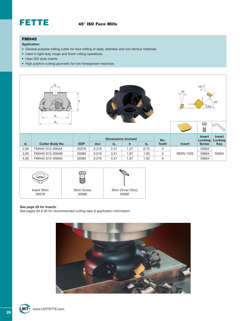
45° ISO Face Mills
Insert InsertDimensions (inches) No. Locking Locking
d1 Cutter Body No. EDP doc d3 h d2 Teeth Insert Screw Key
2.00 FMH45 S12-200AA 50378 0.216 2.51 1.57 0.75 4 50652
3.00 FMH45 S12-300AB 50380 0.216 3.51 1.97 1.00 5 SEKN 1203 50654 50264
4.00 FMH45 S12-400AD 50382 0.216 4.51 1.97 1.50 6 50654
10°
19°
doc
45°
FMH45Application
• General purpose milling cutter for face milling of steel, stainless and non-ferrous materials
• Used in light-duty rough and finish milling operations
• Uses ISO style inserts
• High positive cutting geometry for low horsepower machines
See page 29 for Inserts.See pages 94 & 95 for recommended cutting data & application information.
Insert Shim50578
Shim Screw50580
Shim Driver (Torx)50582
d2
d1
d3
h

27www.LMTFETTE.com
45° ISO Face Mills
Wedge WedgeDimensions (inches) No. Clamp Driver
d1 Cutter Body No. EDP doc d3 h d2 Teeth Insert Assembly (Torx)
Coarse Pitch
4.00 MMH45 S12-3-400AD 50001 0.216 4.51 2.48 1.50 6
5.00 MMH45 S12-3-500AD 50002 0.216 5.51 2.48 1.50 6
6.00 MMH45 S12-3-600AD 50003 0.216 6.51 2.48 1.50 10
8.00 MMH45 S12-3-800AF 50004 0.216 8.51 2.48 2.50 12SEKN 1203
10.00 MMH45 S12-3-1000AF 50005 0.216 10.51 2.48 2.50 1450260 50262
12.00 MMH45 S12-3-1200AF 50006 0.216 12.51 3.15 2.50 18
16.00 MMH45 S12-3-1600AF 50007 0.216 16.51 3.15 2.50 20
20.00 MMH45 S12-3-2000AF 50008 0.216 20.51 3.15 2.50 28
Fine Pitch
5.00 MMH45 S12-3-500ADF 50009 0.216 5.51 2.48 1.50 8
6.00 MMH45 S12-3-600ADF 50010 0.216 6.51 2.48 1.50 12
8.00 MMH45 S12-3-800AFF 50011 0.216 8.51 2.48 2.50 16
10.00 MMH45 S12-3-1000AFF 50012 0.216 10.51 2.48 2.50 20 SEKN 1203 50260 50262
12.00 MMH45 S12-3-1200AFF 50013 0.216 12.51 3.15 2.50 24
16.00 MMH45 S12-3-1600AFF 50014 0.216 16.51 3.15 2.50 30
20.00 MMH45 S12-3-2000AFF 50015 0.216 20.51 3.15 2.50 40
10°
19°
doc45°
MMH45 S12Application
• General purpose modular milling cutter for face milling of steel, stainless and non-ferrous materials
• Used in light-duty rough and finish milling operations
• Uses ISO style inserts
• High positive cutting geometry
• Smooth cutting action on low horsepower machines
• Cartridge design interchangeable with other LMT Multi-Mills
• Available in coarse and fine pitch
Cartridge50237
Cartridge Screw50253
Cartridge Key50254
Wedge Screw50261
Adjustment Screw50263
Adjustment Key50264
See page 29 for Inserts.See pages 94 & 95 for recommended cutting data & application information. Refer to page 111 in technical section for Multi-Mill assembly and adjustment instructions.
Multi-Mills furnished with cartridges and hardware. Inserts must be ordered separately.
d3
h
d2
d1
45°
28www.LMTFETTE.com
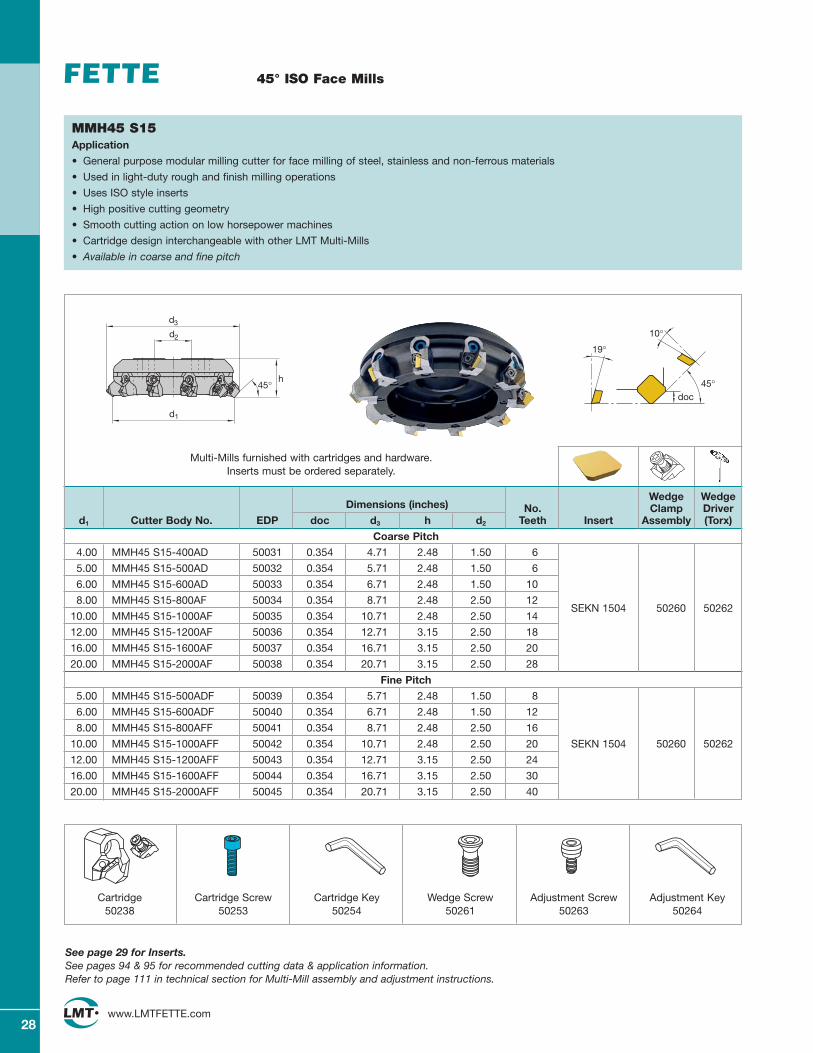
45° ISO Face Mills
MMH45 S15Application
• General purpose modular milling cutter for face milling of steel, stainless and non-ferrous materials
• Used in light-duty rough and finish milling operations
• Uses ISO style inserts
• High positive cutting geometry
• Smooth cutting action on low horsepower machines
• Cartridge design interchangeable with other LMT Multi-Mills
• Available in coarse and fine pitch
Wedge WedgeDimensions (inches) No. Clamp Driver
d1 Cutter Body No. EDP doc d3 h d2 Teeth Insert Assembly (Torx)
Coarse Pitch
4.00 MMH45 S15-400AD 50031 0.354 4.71 2.48 1.50 6
5.00 MMH45 S15-500AD 50032 0.354 5.71 2.48 1.50 6
6.00 MMH45 S15-600AD 50033 0.354 6.71 2.48 1.50 10
8.00 MMH45 S15-800AF 50034 0.354 8.71 2.48 2.50 12SEKN 1504
10.00 MMH45 S15-1000AF 50035 0.354 10.71 2.48 2.50 1450260 50262
12.00 MMH45 S15-1200AF 50036 0.354 12.71 3.15 2.50 18
16.00 MMH45 S15-1600AF 50037 0.354 16.71 3.15 2.50 20
20.00 MMH45 S15-2000AF 50038 0.354 20.71 3.15 2.50 28
Fine Pitch
5.00 MMH45 S15-500ADF 50039 0.354 5.71 2.48 1.50 8
6.00 MMH45 S15-600ADF 50040 0.354 6.71 2.48 1.50 12
8.00 MMH45 S15-800AFF 50041 0.354 8.71 2.48 2.50 16
10.00 MMH45 S15-1000AFF 50042 0.354 10.71 2.48 2.50 20 SEKN 1504 50260 50262
12.00 MMH45 S15-1200AFF 50043 0.354 12.71 3.15 2.50 24
16.00 MMH45 S15-1600AFF 50044 0.354 16.71 3.15 2.50 30
20.00 MMH45 S15-2000AFF 50045 0.354 20.71 3.15 2.50 40
10°
19°
doc45°
Cartridge50238
Cartridge Screw50253
Cartridge Key50254
Wedge Screw50261
Adjustment Screw50263
Adjustment Key50264
See page 29 for Inserts.See pages 94 & 95 for recommended cutting data & application information. Refer to page 111 in technical section for Multi-Mill assembly and adjustment instructions.
Multi-Mills furnished with cartridges and hardware. Inserts must be ordered separately.
d3
h
d2
d1
45°
29www.LMTFETTE.com
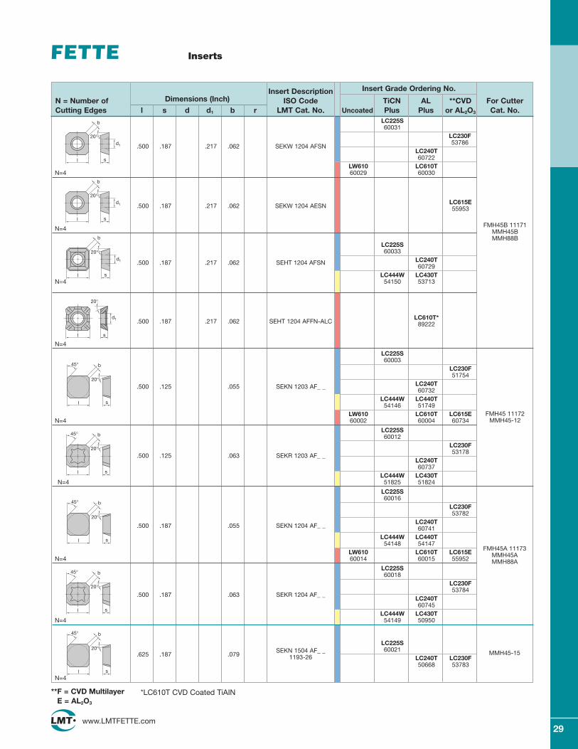
Inserts
Insert Description Insert Grade Ordering No.
N = Number of Dimensions (Inch) ISO Code TiCN AL **CVD For CutterCutting Edges l s d d1 b r LMT Cat. No. Uncoated Plus Plus or AL2O3 Cat. No.
20°
sl
d1
b
sl
d1
20°
LC225S60031
LC230F
.500 .187 .217 .062 SEKW 1204 AFSN53786
LC240T60722
LW610 LC610TN=4 60029 60030
.500 .187 .217 .062 SEKW 1204 AESNLC615E55953
N=4
LC225S60033
LC240T.500 .187 .217 .062 SEHT 1204 AFSN60729
LC444W LC430TN=4 54150 53713
.500 .187 .217 .062 SEHT 1204 AFFN-ALCLC610T*
89222
N=4
LC225S60003
LC230F51754
.500 .125 .055 SEKN 1203 AF_ _ LC240T60732
LC444W LC440T54146 51749
LW610 LC610T LC615EN=4 60002 60004 60734
LC225S60012
LC230F
.500 .125 .063 SEKR 1203 AF_ _53178
LC240T60737
LC444W LC430TN=4 51825 51824
LC225S60016
LC230F53782
.500 .187 .055 SEKN 1204 AF_ _LC240T60741
LC444W LC440T54148 54147
LW610 LC610T LC615EN=4 60014 60015 55952
LC225S60018
LC230F
.500 .187 .063 SEKR 1204 AF_ _53784
LC240T60745
LC444W LC430TN=4 54149 50950
LC225S
.625 .187 .079 SEKN 1504 AF_ _ 60021
1193-26 LC240T LC230F50668 53783
N=4
l
b
20°
s
d1
sl
20°
b45°
s
20°
l
b45°
sl
20°
b45°
s
20°
l
b45°
sl
20°
b45°
*LC610T CVD Coated TiAIN
FMH45B 11171MMH45B MMH88B
FMH45 11172MMH45-12
FMH45A 11173MMH45AMMH88A
MMH45-15
**F = CVD MultilayerE = AL2O3
l
b
20°
s
d1
30www.LMTFETTE.com
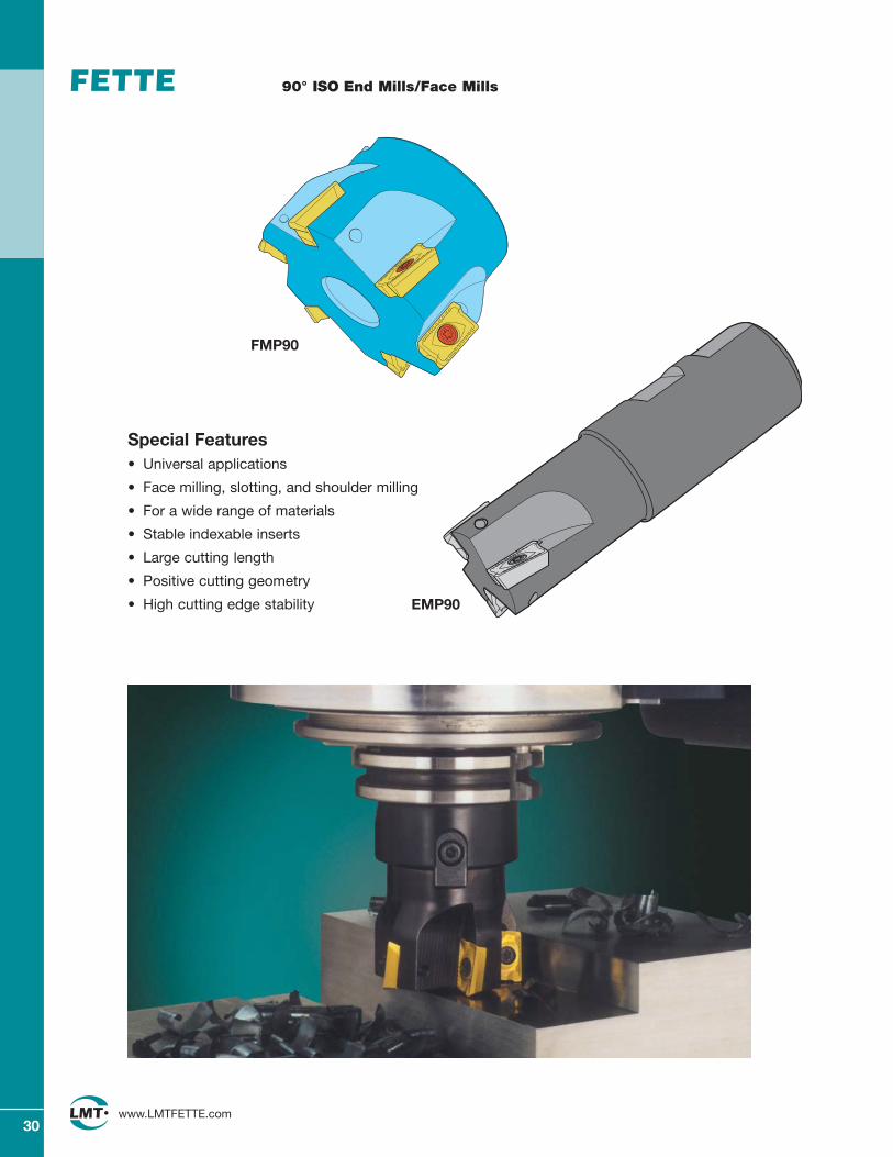
90° ISO End Mills/Face Mills
Special Features• Universal applications
• Face milling, slotting, and shoulder milling
• For a wide range of materials
• Stable indexable inserts
• Large cutting length
• Positive cutting geometry
• High cutting edge stability
FMP90
EMP90
31www.LMTFETTE.com
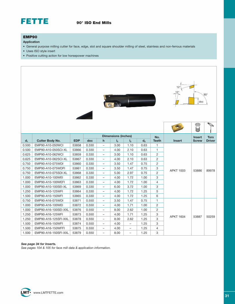
90° ISO End Mills
EMP90Application
• General purpose milling cutter for face, edge, slot and square shoulder milling of steel, stainless and non-ferrous materials
• Uses ISO style insert
• Positive cutting action for low horsepower machines
90°
doc
12°
12°
See page 34 for Inserts.See pages 104 & 105 for face mill data & application information.
Dimensions (inches) No. Insert Torxd1 Cutter Body No. EDP doc h l3 l2 d2 Teeth Insert Screw Driver
0.500 EMP90-A10-050WCI 53858 0.330 – 3.00 1.10 0.63 1
0.500 EMP90-A10-050SCI-XL 53866 0.330 – 4.00 2.10 0.63 1
0.625 EMP90-A10-062WCI 53859 0.330 – 3.00 1.10 0.63 2
0.625 EMP90-A10-062SCI-XL 53867 0.330 – 4.00 2.10 0.63 2
0.750 EMP90-A10-075WDI 53860 0.330 – 3.50 1.47 0.75 2
0.750 EMP90-A10-075WDFI 53861 0.330 – 3.50 1.47 0.75 3APKT 1003 53886 89978
0.750 EMP90-A10-075SDI-XL 53868 0.330 – 5.00 2.97 0.75 2
1.000 EMP90-A10-100WEI 53862 0.330 – 4.00 1.72 1.00 3
1.000 EMP90-A10-100WEFI 53863 0.330 – 4.00 1.72 1.00 4
1.000 EMP90-A10-100SEI-XL 53869 0.330 – 6.00 3.72 1.00 3
1.250 EMP90-A10-125WFI 53864 0.330 – 4.00 1.72 1.25 5
1.500 EMP90-A10-150WFI 53865 0.330 – 4.00 1.72 1.25 6
0.750 EMP90-A16-075WDI 53871 0.550 – 3.50 1.47 0.75 1
1.000 EMP90-A16-100WEI 53872 0.550 – 4.00 1.71 1.00 2
1.000 EMP90-A16-100SEI-XXL 53876 0.550 – 8.00 2.62 1.00 2
1.250 EMP90-A16-125WFI 53873 0.550 – 4.00 1.71 1.25 3APKT 1604 53887 50259
1.250 EMP90-A16-125SFI-XXL 53878 0.550 – 8.00 2.62 1.25 3
1.500 EMP90-A16-150WFI 53874 0.550 – 4.00 – 1.25 3
1.500 EMP90-A16-150WFFI 53875 0.550 – 4.00 – 1.25 4
1.500 EMP90-A16-150SFI-XXL 53879 0.550 – 8.00 – 1.25 3
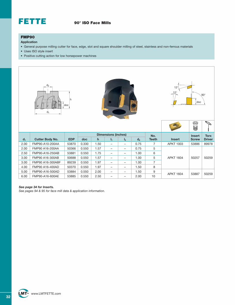
90° ISO Face Mills
32www.LMTFETTE.com
FMP90Application
• General purpose milling cutter for face, edge, slot and square shoulder milling of steel, stainless and non-ferrous materials
• Uses ISO style insert
• Positive cutting action for low horsepower machines
Dimensions (inches) No. Insert Torxd1 Cutter Body No. EDP doc h l1 l3 d2 Teeth Insert Screw Driver
2.00 FMP90-A10-200AA 53870 0.330 1.50 – – 0.75 7 APKT 1003 53886 89978
2.00 FMP90 A16-200AA 50366 0.550 1.57 – – 0.75 5
2.50 FMP90-A16-250AB 53881 0.550 1.75 – – 1.00 6
3.00 FMP90 A16-300AB 50688 0.550 1.57 – – 1.00 5 APKT 1604 50257 50259
3.00 FMP90 A16-300ABF 89239 0.550 1.97 – – 1.00 7
4.00 FMP90 A16-400AD 50370 0.550 1.97 – – 1.50 8
5.00 FMP90-A16-500AD 53884 0.550 2.00 – – 1.50 9APKT 1604 53887 50259
6.00 FMP90-A16-600AE 53885 0.550 2.50 – – 2.00 10
90°
doc
12°
12°
See page 34 for Inserts.See pages 94 & 95 for face mill data & application information.
d2
d1
h
doc
33www.LMTFETTE.com
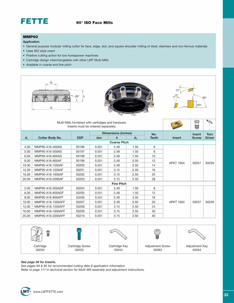
90° ISO Face Mills
Dimensions (inches) No. Insert Torxd1 Cutter Body No. EDP doc h d2 Teeth Insert Screw Driver
Coarse Pitch
4.00 MMP90 A16-400AD 50196 0.551 2.48 1.50 6
5.00 MMP90 A16-500AD 50197 0.551 2.48 1.50 6
6.00 MMP90 A16-600AD 50198 0.551 2.48 1.50 10
8.00 MMP90 A16-800AF 50199 0.551 2.48 2.50 12
10.00 MMP90 A16-1000AF 50200 0.551 2.48 2.50 14APKT 1604 50257 50259
12.00 MMP90 A16-1200AF 50201 0.551 3.15 2.50 18
16.00 MMP90 A16-1600AF 50202 0.551 3.15 2.50 20
20.00 MMP90 A16-2000AF 50203 0.551 3.15 2.50 28
Fine Pitch
5.00 MMP90 A16-500ADF 50204 0.551 2.48 1.50 8
6.00 MMP90 A16-600ADF 50205 0.551 2.48 1.50 12
8.00 MMP90 A16-800AFF 50206 0.551 2.48 2.50 16
10.00 MMP90 A16-1000AFF 50207 0.551 2.48 2.50 20 APKT 1604 50257 50259
12.00 MMP90 A16-1200AFF 50208 0.551 3.15 2.50 24
16.00 MMP90 A16-1600AFF 50209 0.551 3.15 2.50 30
20.00 MMP90 A16-2000AFF 50210 0.551 3.15 2.50 40
90°
doc
12°
12°
MMP90Application
• General purpose modular milling cutter for face, edge, slot, and square shoulder milling of steel, stainless and non-ferrous materials
• Uses ISO style insert
• Positive cutting action for low horsepower machines
• Cartridge design interchangeable with other LMT Multi-Mills
• Available in coarse and fine pitch
Cartridge50250
Cartridge Screw50253
Cartridge Key50254
Adjustment Screw50263
Adjustment Key50264
See page 34 for Inserts.See pages 94 & 95 for recommended cutting data & application information. Refer to page 111 in technical section for Multi-Mill assembly and adjustment instructions.
Multi-Mills furnished with cartridges and hardware. Inserts must be ordered separately.
90° h
d1
d2
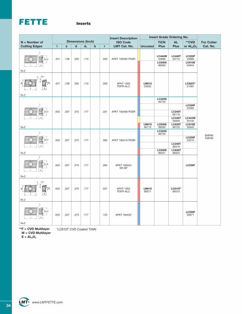
LC444W LC440T LC230F.431 .138 .262 .110 .020 APKT 100305 PDSR 53889 53712 53889
LC630S LC615E89363 55944
N=2
.431 .138 .262 .110 .020 APHT 1003 LW610 LC620T*PDFR-ALC 53932 51097
N=2
LC225S60120
LC230F53382
.642 .207 .375 .177 .031 APKT 160408 PDSR LC240T60119
LC440T LC444W50949 54145
LW610 LC630S LC630T LC615EN=2 60115 89500 89125 55945
LC225S60720
LC230F.642 .207 .375 .177 .062 APKT 160416 PDSR 53310
LC240T89319
LC630S LC630TN=2 89321 89322
.642 .207 .375 .177 .094 APKT 160424 LC230FSR-BP
N=2
.642 .207 .375 .177 .031 APHT 1604 LW610 LC610T*PDFR-ALC 89311 89310
N=2
LC230F.642 .207 .375 .177 .125 APKT 160432 50671
N=2
34www.LMTFETTE.com
Inserts
Insert Description Insert Grade Ordering No.
N = Number of Dimensions (Inch) ISO Code TiCN AL **CVD For CutterCutting Edges l s d d1 b r LMT Cat. No. Uncoated Plus Plus or AL2O3 Cat. No.
r
d1 d
sl
r
d1 d
sl
d
l
r
s
11°
d1
EMP90FMP90
r
d1 d
sl
r
d1 d
sl
*LC610T CVD Coated TiAIN**F = CVD MultilayerW = CVD MultilayerE = AL2O3
d
l
r
s
11°
d1
r
d1 d
sl
35www.LMTFETTE.com
90° ISO Face Mills
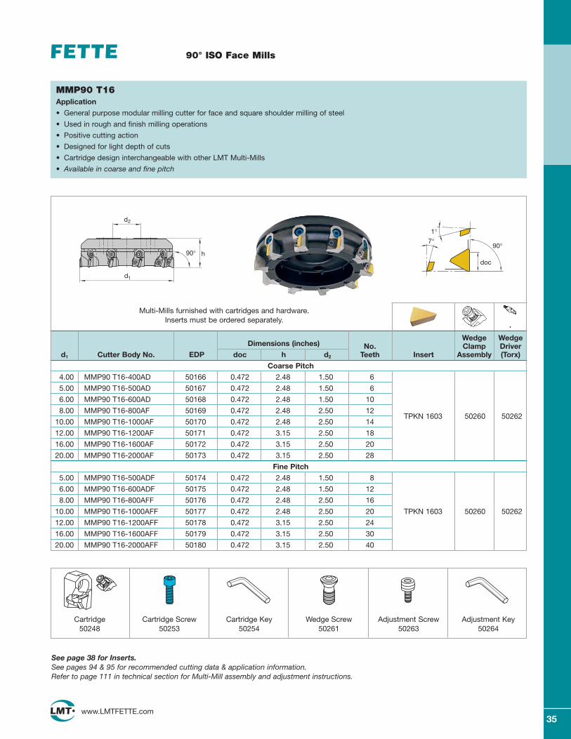
MMP90 T16Application
• General purpose modular milling cutter for face and square shoulder milling of steel
• Used in rough and finish milling operations
• Positive cutting action
• Designed for light depth of cuts
• Cartridge design interchangeable with other LMT Multi-Mills
• Available in coarse and fine pitch
Wedge WedgeDimensions (inches) No. Clamp Driver
d1 Cutter Body No. EDP doc h d2 Teeth Insert Assembly (Torx)
Coarse Pitch
4.00 MMP90 T16-400AD 50166 0.472 2.48 1.50 6
5.00 MMP90 T16-500AD 50167 0.472 2.48 1.50 6
6.00 MMP90 T16-600AD 50168 0.472 2.48 1.50 10
8.00 MMP90 T16-800AF 50169 0.472 2.48 2.50 12TPKN 1603 50260 50262
10.00 MMP90 T16-1000AF 50170 0.472 2.48 2.50 14
12.00 MMP90 T16-1200AF 50171 0.472 3.15 2.50 18
16.00 MMP90 T16-1600AF 50172 0.472 3.15 2.50 20
20.00 MMP90 T16-2000AF 50173 0.472 3.15 2.50 28
Fine Pitch
5.00 MMP90 T16-500ADF 50174 0.472 2.48 1.50 8
6.00 MMP90 T16-600ADF 50175 0.472 2.48 1.50 12
8.00 MMP90 T16-800AFF 50176 0.472 2.48 2.50 16
10.00 MMP90 T16-1000AFF 50177 0.472 2.48 2.50 20 TPKN 1603 50260 50262
12.00 MMP90 T16-1200AFF 50178 0.472 3.15 2.50 24
16.00 MMP90 T16-1600AFF 50179 0.472 3.15 2.50 30
20.00 MMP90 T16-2000AFF 50180 0.472 3.15 2.50 40
90°
doc
7°1°
Cartridge50248
Cartridge Screw50253
Cartridge Key50254
Wedge Screw50261
Adjustment Screw50263
Adjustment Key50264
See page 38 for Inserts.See pages 94 & 95 for recommended cutting data & application information. Refer to page 111 in technical section for Multi-Mill assembly and adjustment instructions.
Multi-Mills furnished with cartridges and hardware. Inserts must be ordered separately.
h
d1
90°
d2
36www.LMTFETTE.com
90° ISO Face Mills
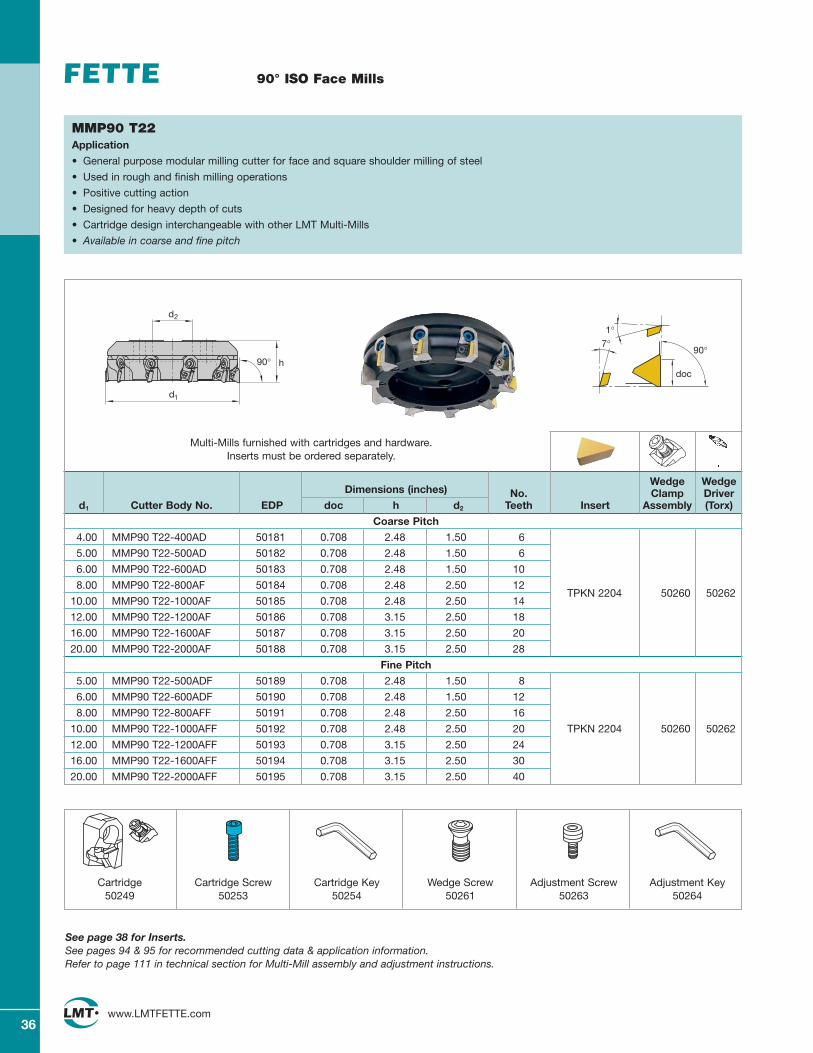
MMP90 T22Application
• General purpose modular milling cutter for face and square shoulder milling of steel
• Used in rough and finish milling operations
• Positive cutting action
• Designed for heavy depth of cuts
• Cartridge design interchangeable with other LMT Multi-Mills
• Available in coarse and fine pitch
Wedge WedgeDimensions (inches) No. Clamp Driver
d1 Cutter Body No. EDP doc h d2 Teeth Insert Assembly (Torx)
Coarse Pitch
4.00 MMP90 T22-400AD 50181 0.708 2.48 1.50 6
5.00 MMP90 T22-500AD 50182 0.708 2.48 1.50 6
6.00 MMP90 T22-600AD 50183 0.708 2.48 1.50 10
8.00 MMP90 T22-800AF 50184 0.708 2.48 2.50 12
10.00 MMP90 T22-1000AF 50185 0.708 2.48 2.50 14TPKN 2204 50260 50262
12.00 MMP90 T22-1200AF 50186 0.708 3.15 2.50 18
16.00 MMP90 T22-1600AF 50187 0.708 3.15 2.50 20
20.00 MMP90 T22-2000AF 50188 0.708 3.15 2.50 28
Fine Pitch
5.00 MMP90 T22-500ADF 50189 0.708 2.48 1.50 8
6.00 MMP90 T22-600ADF 50190 0.708 2.48 1.50 12
8.00 MMP90 T22-800AFF 50191 0.708 2.48 2.50 16
10.00 MMP90 T22-1000AFF 50192 0.708 2.48 2.50 20 TPKN 2204 50260 50262
12.00 MMP90 T22-1200AFF 50193 0.708 3.15 2.50 24
16.00 MMP90 T22-1600AFF 50194 0.708 3.15 2.50 30
20.00 MMP90 T22-2000AFF 50195 0.708 3.15 2.50 40
90°
doc
7°1°
Cartridge50249
Cartridge Screw50253
Cartridge Key50254
Wedge Screw50261
Adjustment Screw50263
Adjustment Key50264
See page 38 for Inserts.See pages 94 & 95 for recommended cutting data & application information. Refer to page 111 in technical section for Multi-Mill assembly and adjustment instructions.
Multi-Mills furnished with cartridges and hardware. Inserts must be ordered separately.
h
d1
90°
d2
37www.LMTFETTE.com
75° ISO Face Mills
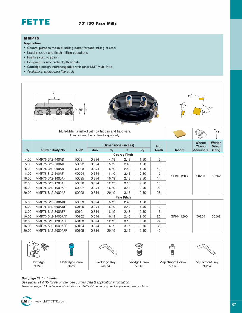
MMP75Application
• General purpose modular milling cutter for face milling of steel
• Used in rough and finish milling operations
• Positive cutting action
• Designed for moderate depth of cuts
• Cartridge design interchangeable with other LMT Multi-Mills
• Available in coarse and fine pitch
Wedge WedgeDimensions (inches) No. Clamp Driver
d1 Cutter Body No. EDP doc d3 h d2 Teeth Insert Assembly (Torx)
Coarse Pitch
4.00 MMP75 S12-400AD 50091 0.354 4.19 2.48 1.50 6
5.00 MMP75 S12-500AD 50092 0.354 5.19 2.48 1.50 6
6.00 MMP75 S12-600AD 50093 0.354 6.19 2.48 1.50 10
8.00 MMP75 S12-800AF 50094 0.354 8.19 2.48 2.50 12
10.00 MMP75 S12-1000AF 50095 0.354 10.19 2.48 2.50 14SPKN 1203 50260 50262
12.00 MMP75 S12-1200AF 50096 0.354 12.19 3.15 2.50 18
16.00 MMP75 S12-1600AF 50097 0.354 16.19 3.15 2.50 20
20.00 MMP75 S12-2000AF 50098 0.354 20.19 3.15 2.50 28
Fine Pitch
5.00 MMP75 S12-500ADF 50099 0.354 5.19 2.48 1.50 8
6.00 MMP75 S12-600ADF 50100 0.354 6.19 2.48 1.50 12
8.00 MMP75 S12-800AFF 50101 0.354 8.19 2.48 2.50 16
10.00 MMP75 S12-1000AFF 50102 0.354 10.19 2.48 2.50 20 SPKN 1203 50260 50262
12.00 MMP75 S12-1200AFF 50103 0.354 12.19 3.15 2.50 24
16.00 MMP75 S12-1600AFF 50104 0.354 16.19 3.15 2.50 30
20.00 MMP75 S12-2000AFF 50105 0.354 20.19 3.15 2.50 40
75°doc
1°
7°
Cartridge50243
Cartridge Screw50253
Cartridge Key50254
Wedge Screw50261
Adjustment Screw50263
Adjustment Key50264
See page 38 for Inserts.See pages 94 & 95 for recommended cutting data & application information. Refer to page 111 in technical section for Multi-Mill assembly and adjustment instructions.
Multi-Mills furnished with cartridges and hardware. Inserts must be ordered separately.
h
d1
75°
d2
d3
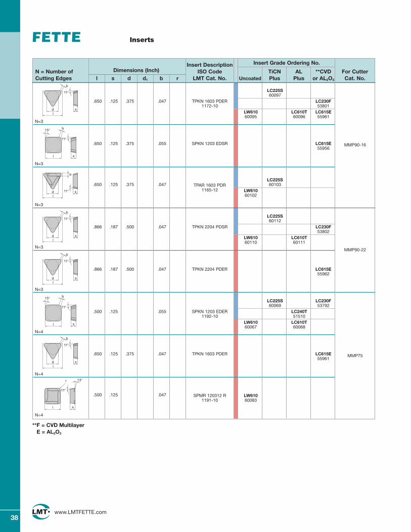
LC225S60097
.650 .125 .375 .047 TPKN 1603 PDER LC230F1172-10 53801
LW610 LC610T LC615E60095 60096 55961
N=3
.650 .125 .375 .055 SPKN 1203 EDSR LC615E55956
N=3
LC225S.650 .125 .375 .047 TPAR 1603 PDR 60103
1165-12 LW61060102
N=3
LC225S60112
.866 .187 .500 .047 TPKN 2204 PDSR LC230F53802
LW610 LC610T60110 60111
N=3
.866 .187 .500 .047 TPKN 2204 PDER LC615E55962
N=3
LC225S LC230F60069 53792
.500 .125 .055 SPKN 1203 EDER LC240T1192-10 51510
LW610 LC610T60067 60068
N=4
.650 .125 .375 .047 TPKN 1603 PDER LC615E55961
N=4
.500 .125 .047 SPMR 120312 R LW6101191-10 60083
N=4
38www.LMTFETTE.com
Inserts
Insert Description Insert Grade Ordering No.
N = Number of Dimensions (Inch) ISO Code TiCN AL **CVD For CutterCutting Edges l s d d1 b r LMT Cat. No. Uncoated Plus Plus or AL2O3 Cat. No.
b
d sl
11°
b
d sl
11°
15° b
sl
11°
MMP90-16
MMP90-22
13°
11°
r
sl
b
d sl
11°
MMP75
**F = CVD MultilayerE = AL2O3
15° b
sl
11°
b
d sl
11°
b
d sl
11°
39www.LMTFETTE.com
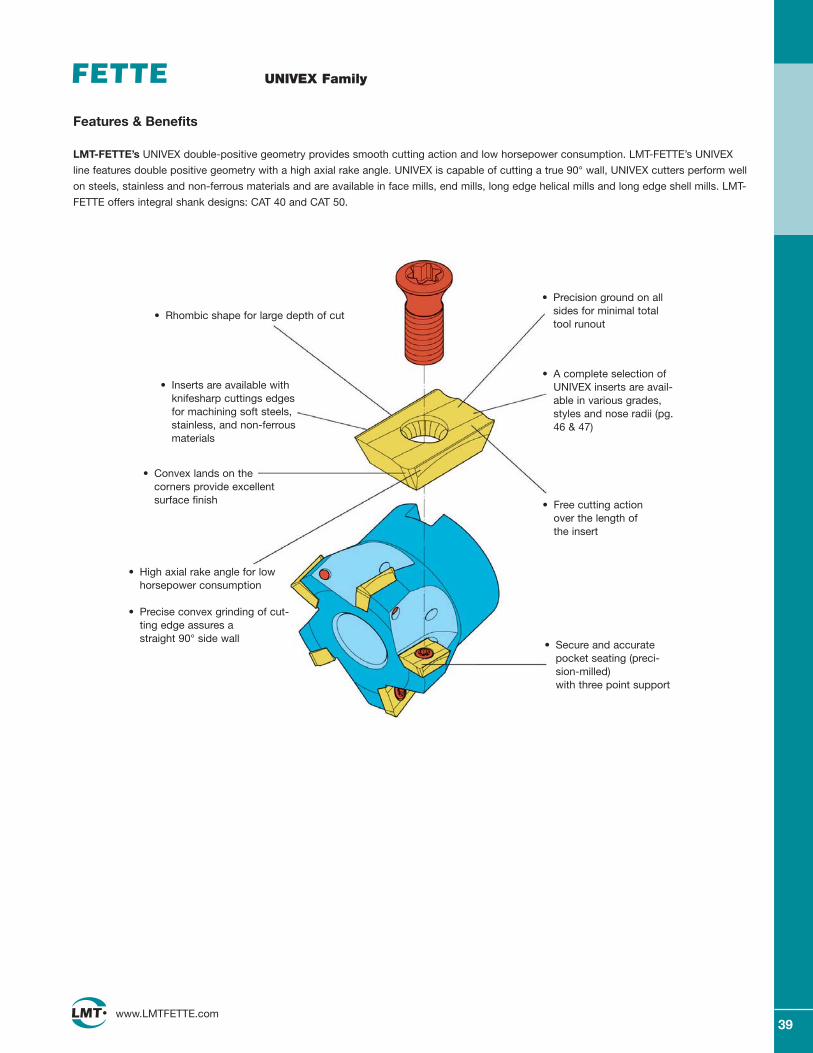
UNIVEX Family
• Rhombic shape for large depth of cut
• Inserts are available withknifesharp cuttings edgesfor machining soft steels,stainless, and non-ferrousmaterials
• Precision ground on allsides for minimal totaltool runout
• High axial rake angle for lowhorsepower consumption
• Precise convex grinding of cut-ting edge assures a straight 90° side wall
• Free cutting actionover the length ofthe insert
• Secure and accuratepocket seating (preci-sion-milled) with three point support
• Convex lands on the corners provide excellent surface finish
Features & Benefits
LMT-FETTE’s UNIVEX double-positive geometry provides smooth cutting action and low horsepower consumption. LMT-FETTE’s UNIVEX
line features double positive geometry with a high axial rake angle. UNIVEX is capable of cutting a true 90° wall, UNIVEX cutters perform well
on steels, stainless and non-ferrous materials and are available in face mills, end mills, long edge helical mills and long edge shell mills. LMT-
FETTE offers integral shank designs: CAT 40 and CAT 50.
• A complete selection of UNIVEX inserts are avail-able in various grades,styles and nose radii (pg.46 & 47)
40www.LMTFETTE.com
40www.LMTFETTE.com
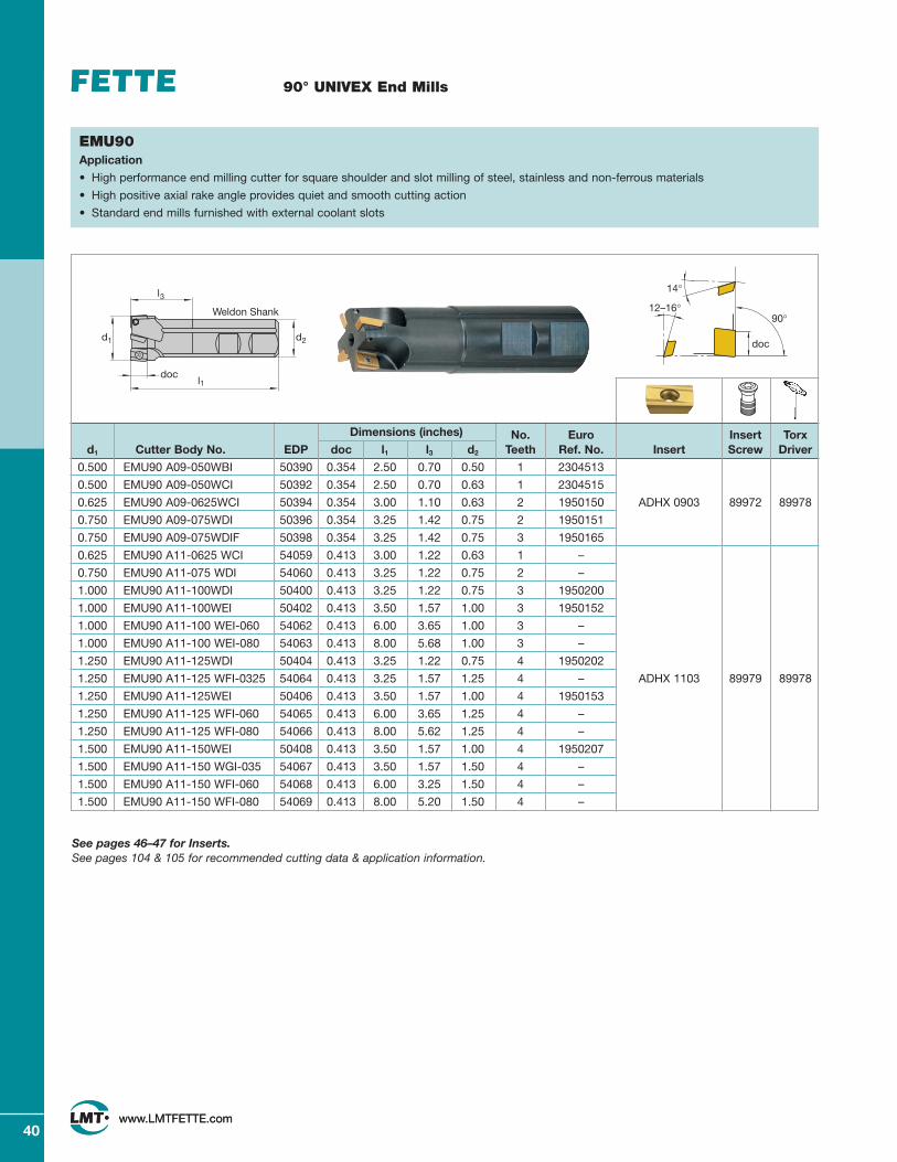
90° UNIVEX End Mills
Dimensions (inches) No. Euro Insert Torxd1 Cutter Body No. EDP doc l1 l3 d2 Teeth Ref. No. Insert Screw Driver
0.500 EMU90 A09-050WBI 50390 0.354 2.50 0.70 0.50 1 2304513
0.500 EMU90 A09-050WCI 50392 0.354 2.50 0.70 0.63 1 2304515
0.625 EMU90 A09-0625WCI 50394 0.354 3.00 1.10 0.63 2 1950150 ADHX 0903 89972 89978
0.750 EMU90 A09-075WDI 50396 0.354 3.25 1.42 0.75 2 1950151
0.750 EMU90 A09-075WDIF 50398 0.354 3.25 1.42 0.75 3 1950165
0.625 EMU90 A11-0625 WCI 54059 0.413 3.00 1.22 0.63 1 –
0.750 EMU90 A11-075 WDI 54060 0.413 3.25 1.22 0.75 2 –
1.000 EMU90 A11-100WDI 50400 0.413 3.25 1.22 0.75 3 1950200
1.000 EMU90 A11-100WEI 50402 0.413 3.50 1.57 1.00 3 1950152
1.000 EMU90 A11-100 WEI-060 54062 0.413 6.00 3.65 1.00 3 –
1.000 EMU90 A11-100 WEI-080 54063 0.413 8.00 5.68 1.00 3 –
1.250 EMU90 A11-125WDI 50404 0.413 3.25 1.22 0.75 4 1950202
1.250 EMU90 A11-125 WFI-0325 54064 0.413 3.25 1.57 1.25 4 – ADHX 1103 89979 89978
1.250 EMU90 A11-125WEI 50406 0.413 3.50 1.57 1.00 4 1950153
1.250 EMU90 A11-125 WFI-060 54065 0.413 6.00 3.65 1.25 4 –
1.250 EMU90 A11-125 WFI-080 54066 0.413 8.00 5.62 1.25 4 –
1.500 EMU90 A11-150WEI 50408 0.413 3.50 1.57 1.00 4 1950207
1.500 EMU90 A11-150 WGI-035 54067 0.413 3.50 1.57 1.50 4 –
1.500 EMU90 A11-150 WFI-060 54068 0.413 6.00 3.25 1.50 4 –
1.500 EMU90 A11-150 WFI-080 54069 0.413 8.00 5.20 1.50 4 –
90°
doc
12–16°
14°
EMU90Application
• High performance end milling cutter for square shoulder and slot milling of steel, stainless and non-ferrous materials
• High positive axial rake angle provides quiet and smooth cutting action
• Standard end mills furnished with external coolant slots
See pages 46–47 for Inserts.See pages 104 & 105 for recommended cutting data & application information.
d2d1
l
Weldon Shank
3
docl1
41www.LMTFETTE.com
41www.LMTFETTE.com
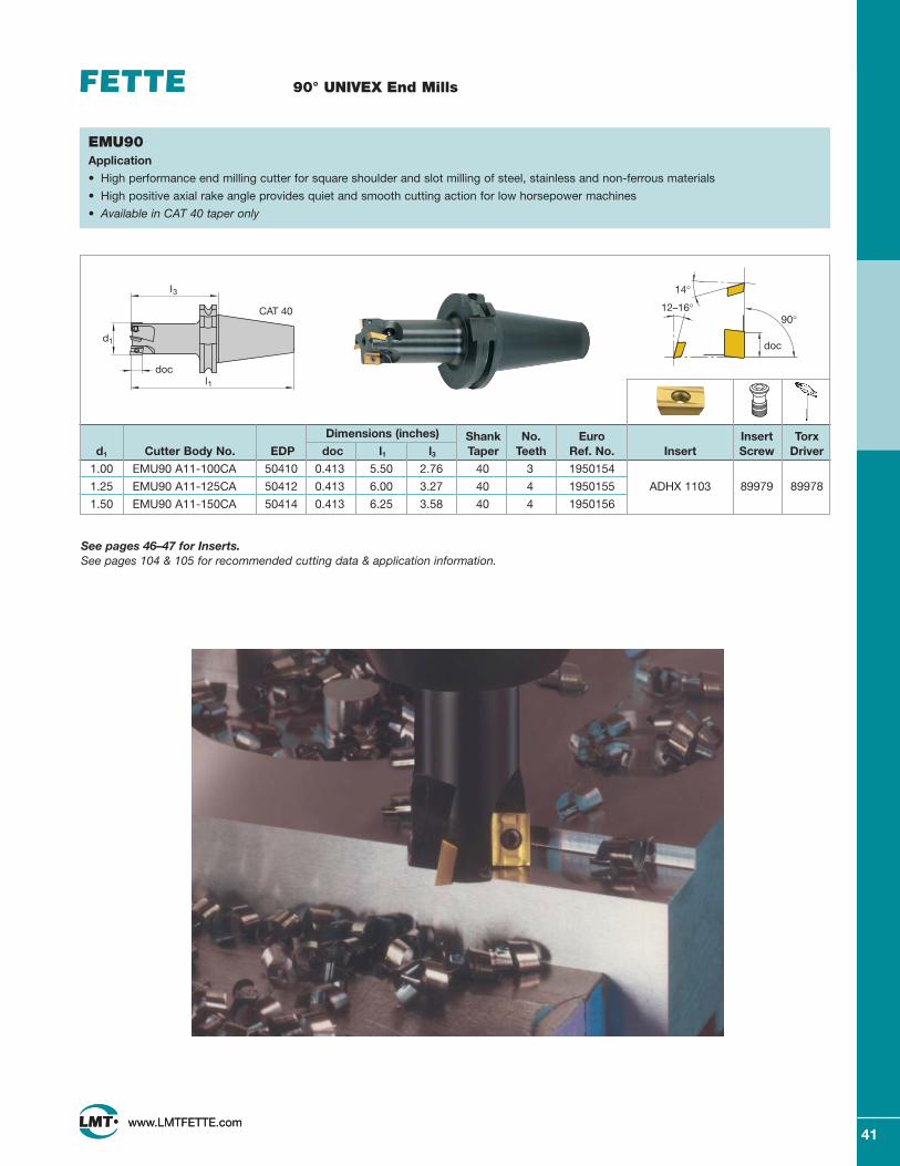
90° UNIVEX End Mills
Dimensions (inches) Shank No. Euro Insert Torxd1 Cutter Body No. EDP doc l1 l3 Taper Teeth Ref. No. Insert Screw Driver
1.00 EMU90 A11-100CA 50410 0.413 5.50 2.76 40 3 1950154
1.25 EMU90 A11-125CA 50412 0.413 6.00 3.27 40 4 1950155 ADHX 1103 89979 89978
1.50 EMU90 A11-150CA 50414 0.413 6.25 3.58 40 4 1950156
90°
doc
12–16°
14°
EMU90Application
• High performance end milling cutter for square shoulder and slot milling of steel, stainless and non-ferrous materials
• High positive axial rake angle provides quiet and smooth cutting action for low horsepower machines
• Available in CAT 40 taper only
See pages 46–47 for Inserts.See pages 104 & 105 for recommended cutting data & application information.
d1
docl1
l
CAT 40
3
42www.LMTFETTE.com
90° UNIVEX End Mills
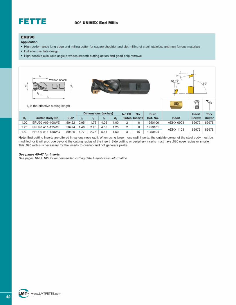
Dimensions (inches) No.Eff. No. Euro Insert Torxd1 Cutter Body No. EDP l2 l3 l1 d2 Flutes Inserts Ref. No. Insert Screw Driver
1.00 ERU90 A09-100WE 50422 0.95 1.75 4.03 1.00 2 6 1950100 ADHX 0903 89972 89978
1.25 ERU90 A11-125WF 50424 1.46 2.25 4.53 1.25 2 8 1950101ADHX 1103 89979 89978
1.50 ERU90 A11-150WG 50426 1.77 2.75 5.44 1.50 3 15 1950104
90°12–16°
14°
ERU90Application
• High performance long edge end milling cutter for square shoulder and slot milling of steel, stainless and non-ferrous materials
• Full effective flute design
• High positive axial rake angle provides smooth cutting action and good chip removal
See pages 46–47 for Inserts.See pages 104 & 105 for recommended cutting data & application information.
lWeldon Shank
3
d1
l2l1
d2
l2 is the effective cutting length
Note: End cutting inserts are offered in various nose radii. When using larger nose radii inserts, the outside corner of the steel body must bemodified, or it will protrude beyond the cutting radius of the insert. Side cutting or periphery inserts must have .020 nose radius or smaller.This .020 radius is necessary for the inserts to overlap and not generate peaks.
43www.LMTFETTE.com
90° UNIVEX Helical End Mills
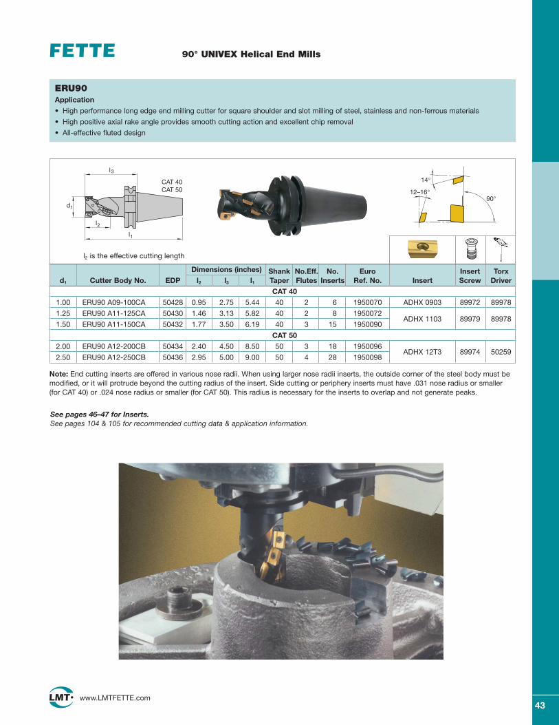
Dimensions (inches) Shank No.Eff. No. Euro Insert Torxd1 Cutter Body No. EDP l2 l3 l1 Taper Flutes Inserts Ref. No. Insert Screw Driver
CAT 40
1.00 ERU90 A09-100CA 50428 0.95 2.75 5.44 40 2 6 1950070 ADHX 0903 89972 89978
1.25 ERU90 A11-125CA 50430 1.46 3.13 5.82 40 2 8 1950072ADHX 1103 89979 89978
1.50 ERU90 A11-150CA 50432 1.77 3.50 6.19 40 3 15 1950090
CAT 50
2.00 ERU90 A12-200CB 50434 2.40 4.50 8.50 50 3 18 1950096ADHX 12T3 89974 50259
2.50 ERU90 A12-250CB 50436 2.95 5.00 9.00 50 4 28 1950098
90°12–16°
14°
ERU90Application
• High performance long edge end milling cutter for square shoulder and slot milling of steel, stainless and non-ferrous materials
• High positive axial rake angle provides smooth cutting action and excellent chip removal
• All-effective fluted design
See pages 46–47 for Inserts.See pages 104 & 105 for recommended cutting data & application information.
Note: End cutting inserts are offered in various nose radii. When using larger nose radii inserts, the outside corner of the steel body must bemodified, or it will protrude beyond the cutting radius of the insert. Side cutting or periphery inserts must have .031 nose radius or smaller (for CAT 40) or .024 nose radius or smaller (for CAT 50). This radius is necessary for the inserts to overlap and not generate peaks.
l2 is the effective cutting length
d1
l1
l2
l
CAT 40CAT 50
3
44www.LMTFETTE.com
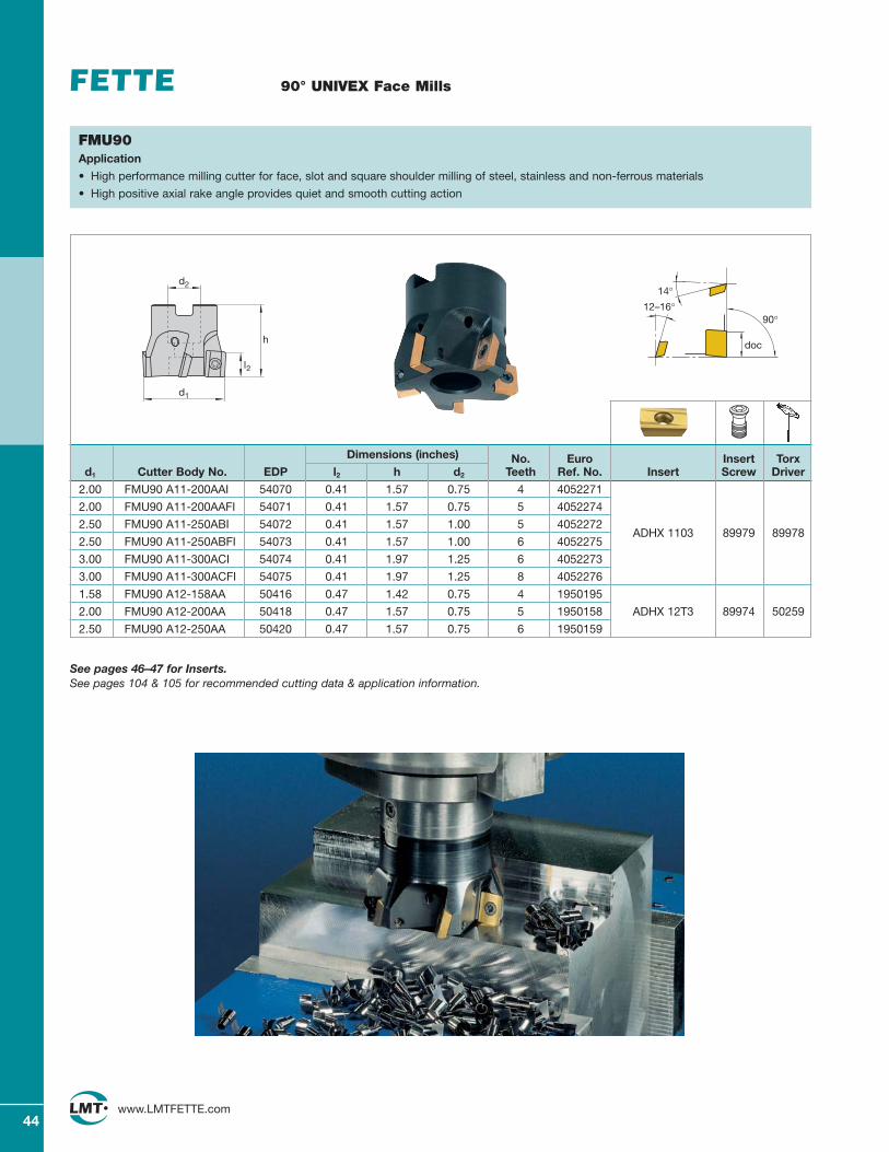
90° UNIVEX Face Mills
FMU90Application
• High performance milling cutter for face, slot and square shoulder milling of steel, stainless and non-ferrous materials
• High positive axial rake angle provides quiet and smooth cutting action
Dimensions (inches) No. Euro Insert Torxd1 Cutter Body No. EDP l2 h d2 Teeth Ref. No. Insert Screw Driver
2.00 FMU90 A11-200AAI 54070 0.41 1.57 0.75 4 4052271
2.00 FMU90 A11-200AAFI 54071 0.41 1.57 0.75 5 4052274
2.50 FMU90 A11-250ABI 54072 0.41 1.57 1.00 5 4052272ADHX 1103 89979 89978
2.50 FMU90 A11-250ABFI 54073 0.41 1.57 1.00 6 4052275
3.00 FMU90 A11-300ACI 54074 0.41 1.97 1.25 6 4052273
3.00 FMU90 A11-300ACFI 54075 0.41 1.97 1.25 8 4052276
1.58 FMU90 A12-158AA 50416 0.47 1.42 0.75 4 1950195
2.00 FMU90 A12-200AA 50418 0.47 1.57 0.75 5 1950158 ADHX 12T3 89974 50259
2.50 FMU90 A12-250AA 50420 0.47 1.57 0.75 6 1950159
90°
doc
12–16°14°
See pages 46–47 for Inserts.See pages 104 & 105 for recommended cutting data & application information.
d2
h
d1
l2
45www.LMTFETTE.com
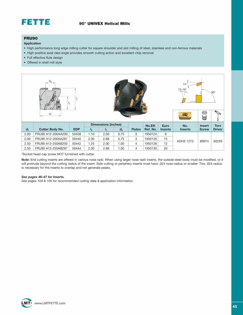
90° UNIVEX Helical Mills
FRU90Application
• High performance long edge milling cutter for square shoulder and slot milling of steel, stainless and non-ferrous materials
• High positive axial rake angle provides smooth cutting action and excellent chip removal
• Full effective flute design
• Offered in shell mill style
Dimensions (inches) No.Eff. Euro No. Insert Torxd1 Cutter Body No. EDP l2 l1 d2 Flutes Ref. No. Inserts Inserts Screw Driver
2.00 FRU90 A12-200AA200 50438 1.10 2.00 0.75 3 1950124 9
2.00 FRU90 A12-200AA287 50440 2.00 2.88 0.75 3 1950126 15ADHX 12T3
2.50 FRU90 A12-250AB200 50442 1.25 2.00 1.00 4 1950128 1289974 50259
2.50 FRU90 A12-250AB287 50444 2.00 2.88 1.00 4 1950130 20
90°12–16°
14°
*Socket head cap screw NOT furnished with cutter.
Note: End cutting inserts are offered in various nose radii. When using larger nose radii inserts, the outside steel body must be modified, or itwill protrude beyond the cutting radius of the insert. Side cutting or periphery inserts must have .024 nose radius or smaller. This .024 radiusis necessary for the inserts to overlap and not generate peaks.
See pages 46–47 for Inserts.See pages 104 & 105 for recommended cutting data & application information.
l2
d2
d1
l1
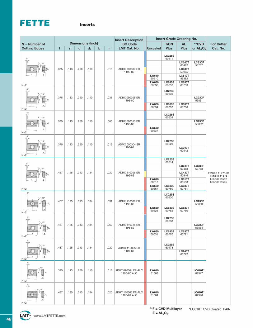
46www.LMTFETTE.com
Inserts
LC225S60511
LC240T LC230F60482 53757
.375 .113 .250 .110 .016 ADHX 090304 ER LC430T1196-80 50965
LW610 LC610T60510 89382LW630 LC630S LC630T
N=2 60538 60752 60753
LC225S60636
.375 .113 .250 .110 .031 ADHX 090308 ER LC230F1196-80 53831
LW630 LC630S LC630T
N=260634 60757 60758
LC225S60639
.375 .113 .250 .110 .060 ADHX 090315 ER LC230F1196-80 53832
LW630
N=260637
LC225S.375 .113 .250 .110 .016 ADMX 090304 ER 60520
1196-81 LC240T60542
N=2
LC225S60514
LC240T LC230F60483 53788
.437 .125 .313 .134 .020 ADHX 110305 ER LC430T1196-82 50946
LW610 LC610T60513 60533LW630 LC630S LC630T
N=2 60667 60760 60761
LC225S60630
.437 .125 .313 .134 .031 ADHX 110308 ER LC230F1196-82 53833
LW630 LC630S LC630T
N=260628 60765 60766
LC225S60633
.437 .125 .313 .134 .060 ADHX 110315 ER LC230F1196-82 53834
LW630 LC630S LC630T
N=260631 60770 60771
LC225S.437 .125 .313 .134 .020 ADMX 110305 ER 60478
1196-83 LC240T60772
N=2
.375 .113 .250 .110 .016 ADHT 090304 FR-ALC LW610 LC610T*1196-80 ALC 51663 89347
N=2
.437 .125 .313 .134 .020 ADHT 110305 FR-ALC LW610 LC610T*1196-82 ALC 51664 89348
N=2
Insert Description Insert Grade Ordering No.
N = Number of Dimensions (Inch) ISO Code TiCN AL **CVD For CutterCutting Edges l s d d1 b r LMT Cat. No. Uncoated Plus Plus or AL2O3 Cat. No.
s
15°
5°
d
l
d1
r
EMU90 11473-ICEMU90 11474ERU90 11552ERU90 11555
s
15°
5°
d
l
d1
r
s
15°
5°
d
l
d1
r
s
15°
5°
d
l
d1
r
s
15°
5°
d
l
d1
r
s
15°
5°
d
l
d1
r
s
15°
5°
d
l
d1
r
s
15°
5°
d
l
d1
r
l
r
d d1
15°
5°
s
l
r
d d1
15°
5°
s
*LC610T CVD Coated TiAIN**F = CVD MultilayerE = AL2O3
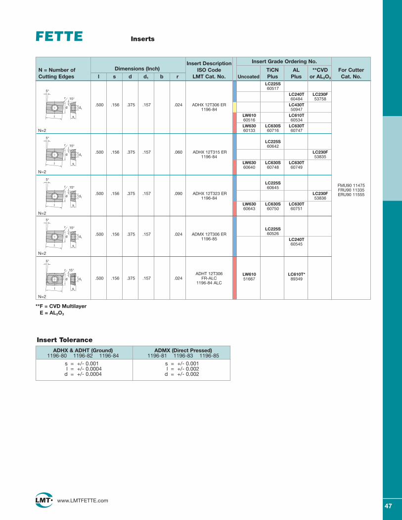
47www.LMTFETTE.com
Inserts
Insert Description Insert Grade Ordering No.
N = Number of Dimensions (Inch) ISO Code TiCN AL **CVD For CutterCutting Edges l s d d1 b r LMT Cat. No. Uncoated Plus Plus or AL2O3 Cat. No.
FMU90 11475FRU90 11335ERU90 11555
s
15°
5°
d
l
d1
r
s
15°
5°
d
l
d1
r
s
15°
5°
d
l
d1
r
s
15°
5°
d
l
d1
r
l
r
d d1
15°
5°
s
LC225S60517
LC240T LC230F60484 53758
.500 .156 .375 .157 .024 ADHX 12T306 ER LC430T1196-84 50947
LW610 LC610T60516 60534LW630 LC630S LC630T
N=2 60133 60716 60747
LC225S60642
.500 .156 .375 .157 .060 ADHX 12T315 ER LC230F1196-84 53835
LW630 LC630S LC630T60640 60748 60749
N=2
LC225S60645
.500 .156 .375 .157 .090 ADHX 12T323 ER LC230F1196-84 53836
LW630 LC630S LC630T60643 60750 60751
N=2
LC225S.500 .156 .375 .157 .024 ADMX 12T306 ER 60526
1196-85 LC240T60545
N=2
ADHT 12T306.500 .156 .375 .157 .024 FR-ALC
LW610 LC610T*
1196-84 ALC51667 89349
N=2
ADHX & ADHT (Ground)1196-80 1196-82 1196-84
s = +/- 0.001l = +/- 0.0004
d = +/- 0.0004
ADMX (Direct Pressed)1196-81 1196-83 1196-85
s = +/- 0.001l = +/- 0.002
d = +/- 0.002
Insert Tolerance
**F = CVD MultilayerE = AL2O3
48www.LMTFETTE.com
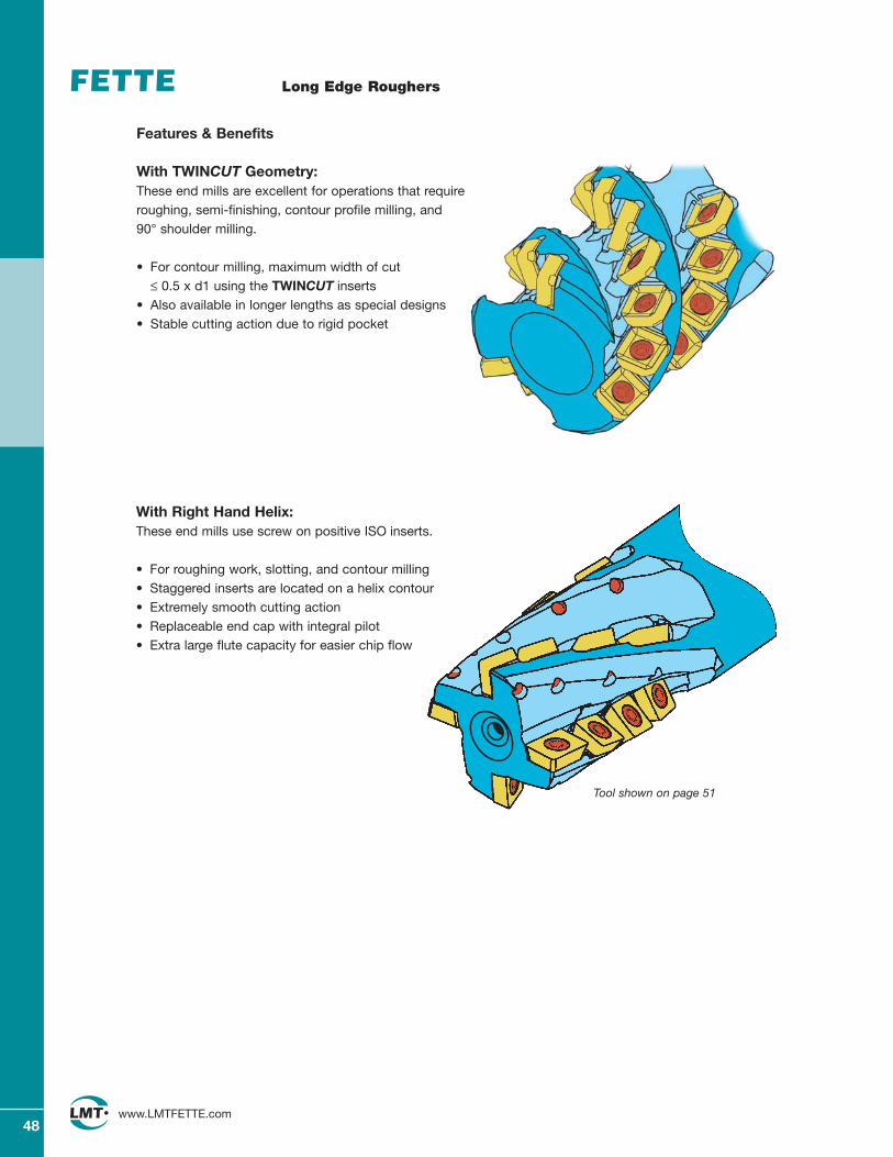
Long Edge Roughers
Features & Benefits
With TWINCUT Geometry:These end mills are excellent for operations that requireroughing, semi-finishing, contour profile milling, and 90° shoulder milling.
• For contour milling, maximum width of cut ≤ 0.5 x d1 using the TWINCUT inserts
• Also available in longer lengths as special designs• Stable cutting action due to rigid pocket
With Right Hand Helix:These end mills use screw on positive ISO inserts.
• For roughing work, slotting, and contour milling• Staggered inserts are located on a helix contour• Extremely smooth cutting action• Replaceable end cap with integral pilot• Extra large flute capacity for easier chip flow
Tool shown on page 51
49www.LMTFETTE.com
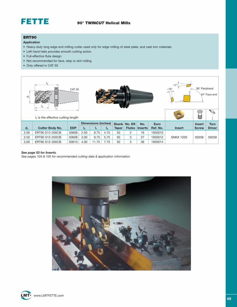
90° TWINCUT Helical Mills
Dimensions (inches) Shank No. Eff. No. Euro Insert Torxd1 Cutter Body No. EDP l2 l1 l3 Taper Flutes Inserts Ref. No. Insert Screw Driver
2.00 ERT90 S12-200CB 50606 2.50 8.75 4.75 50 2 16 1950010
2.50 ERT90 S12-250CB 50608 3.00 9.75 5.75 50 3 27 1950012 SNKX 1205 50256 50258
3.00 ERT90 S12-300CB 50610 4.00 11.75 7.75 50 3 36 1950014
87° Face end
–16°17°
90° Peripheral
ERT90Application
• Heavy-duty long edge end milling cutter used only for edge milling of steel plate, and cast iron materials
• Left hand helix provides smooth cutting action
• Full-effective flute design
• Not recommended for face, step or slot milling
• Only offered in CAT 50
l2 is the effective cutting length
See page 53 for Inserts.See pages 104 & 105 for recommended cutting data & application information.
d1
l
CAT 50
3
l2l1
50www.LMTFETTE.com
90° TWINCUT Helical Mills
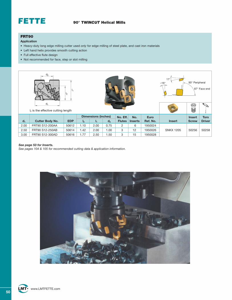
FRT90Application
• Heavy-duty long edge milling cutter used only for edge milling of steel plate, and cast iron materials
• Left hand helix provides smooth cutting action
• Full effective flute design
• Not recommended for face, step or slot milling
l2 is the effective cutting length
Dimensions (inches) No. Eff. No. Euro Insert Torxd1 Cutter Body No. EDP l2 l1 d2 Flutes Inserts Ref. No. Insert Screw Driver
2.00 FRT90 S12-200AA 50612 1.10 2.00 0.75 2 6 1950024
2.50 FRT90 S12-250AB 50614 1.42 2.00 1.00 3 12 1950026 SNKX 1205 50256 50258
3.00 FRT90 S12-300AD 50616 1.77 2.50 1.50 3 15 1950028
87° Face end
–16°17°
90° Peripheral
See page 53 for Inserts.See pages 104 & 105 for recommended cutting data & application information.
d1
l2
d2
l1
51www.LMTFETTE.com
90° Long Edge Helical Mills
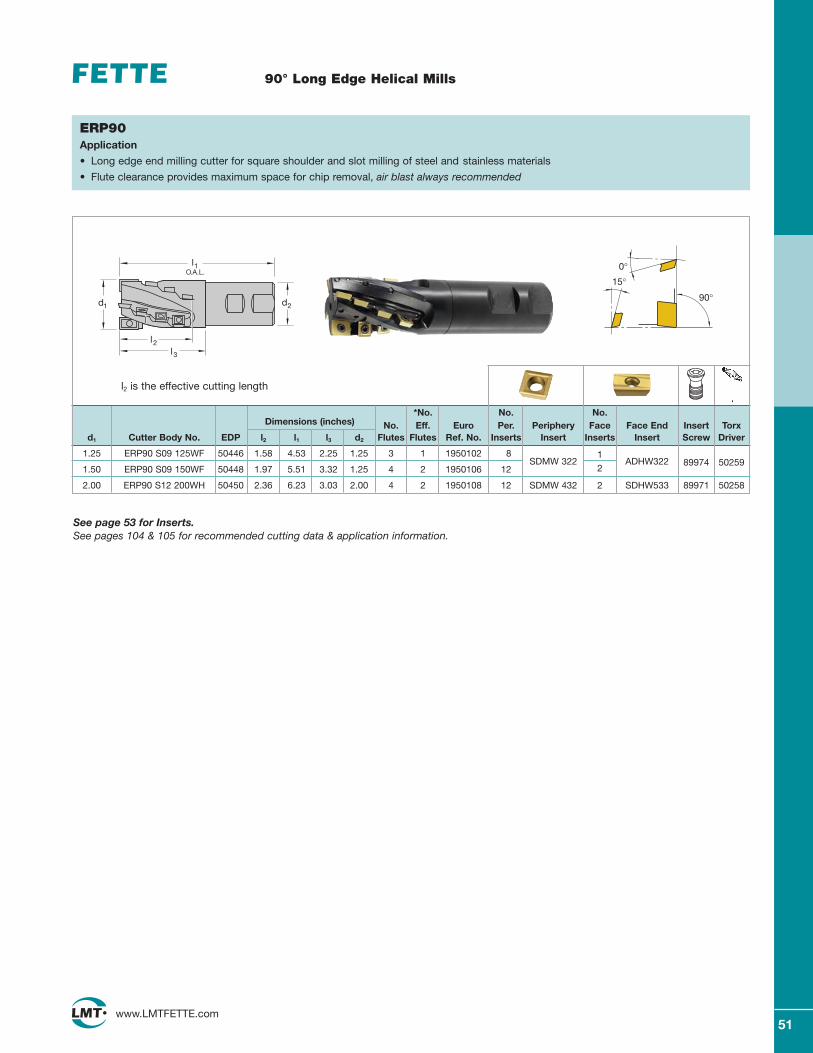
ERP90Application
• Long edge end milling cutter for square shoulder and slot milling of steel and stainless materials
• Flute clearance provides maximum space for chip removal, air blast always recommended
*No. No. No.Dimensions (inches) No. Eff. Euro Per. Periphery Face Face End Insert Torx
d1 Cutter Body No. EDP l2 l1 l3 d2 Flutes Flutes Ref. No. Inserts Insert Inserts Insert Screw Driver
1.25 ERP90 S09 125WF 50446 1.58 4.53 2.25 1.25 3 1 1950102 8SDMW 322
1ADHW322
1.50 ERP90 S09 150WF 50448 1.97 5.51 3.32 1.25 4 2 1950106 12 289974 50259
2.00 ERP90 S12 200WH 50450 2.36 6.23 3.03 2.00 4 2 1950108 12 SDMW 432 2 SDHW533 89971 50258
90°
15°
0°
l2 is the effective cutting length
See page 53 for Inserts.See pages 104 & 105 for recommended cutting data & application information.
l2
d1
l1O.A.L.
d2
l3
52www.LMTFETTE.com
90° ISO Long Edge Helical Mills
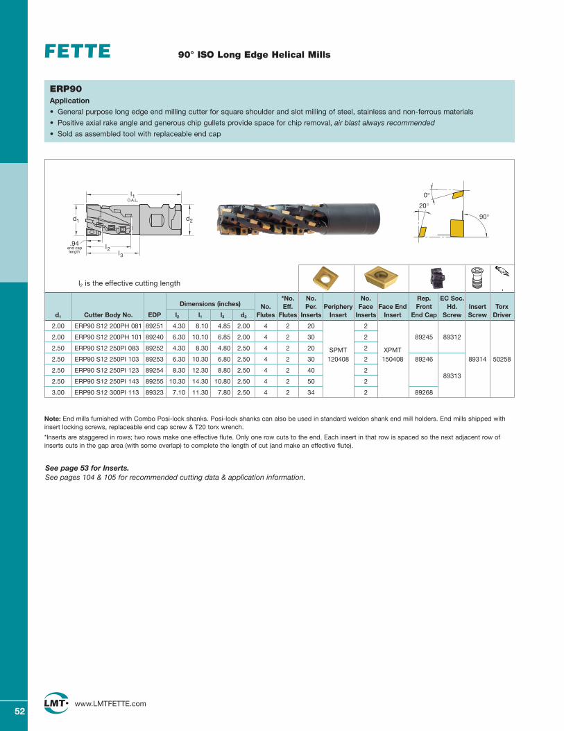
ERP90Application
• General purpose long edge end milling cutter for square shoulder and slot milling of steel, stainless and non-ferrous materials
• Positive axial rake angle and generous chip gullets provide space for chip removal, air blast always recommended
• Sold as assembled tool with replaceable end cap
*No. No. No. Rep. EC Soc.Dimensions (inches) No. Eff. Per. Periphery Face Face End Front Hd. Insert Torx
d1 Cutter Body No. EDP l2 l1 l3 d2 Flutes Flutes Inserts Insert Inserts Insert End Cap Screw Screw Driver
2.00 ERP90 S12 200PH 081 89251 4.30 8.10 4.85 2.00 4 2 20 2
2.00 ERP90 S12 200PH 101 89240 6.30 10.10 6.85 2.00 4 2 30 2 89245 89312
2.50 ERP90 S12 250PI 083 89252 4.30 8.30 4.80 2.50 4 2 20 SPMT 2 XPMT2.50 ERP90 S12 250PI 103 89253 6.30 10.30 6.80 2.50 4 2 30 120408 2 150408 89246 89314 50258
2.50 ERP90 S12 250PI 123 89254 8.30 12.30 8.80 2.50 4 2 40 289313
2.50 ERP90 S12 250PI 143 89255 10.30 14.30 10.80 2.50 4 2 50 2
3.00 ERP90 S12 300PI 113 89323 7.10 11.30 7.80 2.50 4 2 34 2 89268
90°
20°
0°
l2 is the effective cutting length
Note: End mills furnished with Combo Posi-lock shanks. Posi-lock shanks can also be used in standard weldon shank end mill holders. End mills shipped withinsert locking screws, replaceable end cap screw & T20 torx wrench.
*Inserts are staggered in rows; two rows make one effective flute. Only one row cuts to the end. Each insert in that row is spaced so the next adjacent row ofinserts cuts in the gap area (with some overlap) to complete the length of cut (and make an effective flute).
See page 53 for Inserts.See pages 104 & 105 for recommended cutting data & application information.
l2
d1
l1O.A.L.
d2
l3
.94end caplength
53www.LMTFETTE.com
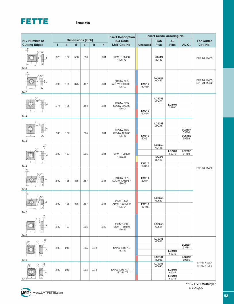
Inserts
Insert Description Insert Grade Ordering No.
N = Number of Dimensions (Inch) ISO Code TiCN AL For CutterCutting Edges l s d d1 b r LMT Cat. No. Uncoated Plus Plus AL2O3 Cat. No.
ERP 90 11453
s
11°
d
l
3°
d1
r
.625 .187 .500 .216 .031 XPMT 150408 LC435I1196-79 89140
N=2
LC225S(ADHW 322) 60442
.500 .125 .375 .157 .031 ADHW 120308 R LW6101196-02 60439
N=2
LC225S60438
(SDMW 322)LC240T.375 .125 .154 .031 SDMW 090308512001196-01
LW61060435
N=4
LC225S60452
(SPMW 432) LC230F.500 .187 .205 .031 SPMW 120408 53800
1196-10 LW610 LC615E60451 55958
N=4
LC225S60458
LC240T LC230F.500 .187 .205 .031 SPMT 120408 60773 51759
1196-12 LC435I89130
LW610N=4 60456
(ADHW 322) LW610.500 .125 .375 .157 .031 ADMW 120308 R 60574
1196-06
N=2
LC225S(ADMT 322) 60649
.500 .125 .375 .157 .031 ADMT 120308 R LW6101196-04 60446
N=2
(SDMT 533) LC225S.630 .197 .205 .039 SDMT 150410 60651
1196-22
N=2
LC225S 60036
LC230F.500 .219 .205 .078 SNKX 1205 AN 53791
1187-10 LC240T60039
LC610T LC615EN=4 89936 89365
LC225S60045
.500 .219 .205 .078 SNKX 1205 AN-TR LC240T1187-10 TR 60047
LC610TN=4 60048
r
s
d1
15°
l
r
s
d1
11°
l
s
d1
l
r
11°
15°
s
15°
5°
d
l
d1
r
s
15°
5°
d
l
d1
r
s
d1
l
r
15°
15°
ERP 90 11453EPR 90 11452
ERP 90 11452
s
15°
5°
l
l
d1
r
b
l s
d1
30°45°
b
s
d1
30°
l
45°ERT90 11257FRT90 11259
**F = CVD MultilayerE = AL2O3
54www.LMTFETTE.com
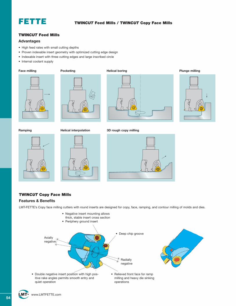
TWINCUT Feed Mills / TWINCUT Copy Face Mills
TWINCUT Copy Face Mills
Features & Benefits
LMT-FETTE’s Copy face milling cutters with round inserts are designed for copy, face, ramping, and contour milling of molds and dies.
• Deep chip groove
• Negative insert mounting allowsthick, stable insert cross section
• Periphery ground insert
• Relieved front face for rampmilling and heavy die sinkingoperations
• Double negative insert position with high pos-itive rake angles permits smooth entry andquiet operation
Radiallynegative
Axiallynegative
Face milling
Ramping
Pocketing
Helical interpolation 3D rough copy milling
Plunge millingHelical boring
TWINCUT Feed Mills
Advantages
• High feed rates with small cutting depths
• Proven indexable insert geometry with optimized cutting edge design
• Indexable insert with three cutting edges and large inscribed circle
• Internal coolant supply
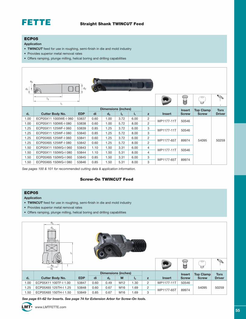
55www.LMTFETTE.com
Straight Shank TWINCUT Feed
Dimensions (inches) Insert Top Clamp Torxd1 Cutter Body No. EDP di d2 l3 l1 z Insert Screw Screw Driver
1.00 ECP05X11 1000WE-I 060 53837 0.60 1.00 3.72 6.00 2WP1177-11T 50546
1.00 ECP05X11 100WE-I 080 53838 0.60 1.00 5.72 8.00 2
1.25 ECP05X11 125WF-I 060 53839 0.85 1.25 3.72 6.00 3WP1177-11T 50546
1.25 ECP05X11 125WF-I 080 53840 0.85 1.25 5.72 8.00 3
1.25 ECP05X65 125WF-I 060 53841 0.60 1.25 3.72 6.00 2WP1177-65T 89974 54095 50259
1.25 ECP05X65 125WF-I 080 53842 0.60 1.25 5.72 8.00 2
1.50 ECP05X11 150WG-I 060 53843 1.10 1.50 3.31 6.00 4WP1177-11T 50546
1.50 ECP05X11 150WG-I 080 53844 1.10 1.50 5.31 8.00 4
1.50 ECP05X65 150WG-I 060 53845 0.85 1.50 3.31 6.00 3WP1177-65T 89974
1.50 ECP05X65 150WG-I 080 53846 0.85 1.50 5.31 8.00 3
ECP05Application
• TWINCUT feed for use in roughing, semi-finish in die and mold industry
• Provides superior metal removal rates
• Offers ramping, plunge milling, helical boring and drilling capabilities
Dimensions (inches) Insert Top Clamp Torxd1 Cutter Body No. EDP di d2 M l3 z Insert Screw Screw Driver
1.00 ECP05X11 100TF-I 1.00 53847 0.60 0.49 M12 1.30 2 WP1177-11T 50546
1.25 ECP05X65 125TH-I 1.25 53848 0.60 0.67 M16 1.69 2WP1177-65T 89974
54095 50259
1.50 ECP05X65 150TH-I 1.50 53849 0.85 0.67 M16 1.69 3
ECP05Application
• TWINCUT feed for use in roughing, semi-finish in die and mold industry
• Provides superior metal removal rates
• Offers ramping, plunge milling, helical boring and drilling capabilities
Screw-On TWINCUT Feed
l1
l3
d2d1
ap
d1
ap
l1
d2
d3
d5
See page 61–62 for Inserts. See page 74 for Extension Arbor for Screw-On tools.
See pages 100 & 101 for recommended cutting data & application information.
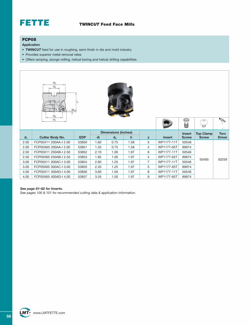
56www.LMTFETTE.com
TWINCUT Feed Face Mills
FCP05Application
• TWINCUT feed for use in roughing, semi-finish in die and mold industry
• Provides superior metal removal rates
• Offers ramping, plunge milling, helical boring and helical drilling capabilities
Dimensions (inches) Insert Top Clamp Torxd1 Cutter Body No. EDP di d2 h z Insert Screw Screw Driver
2.00 FCP05X11 200AA-I 2.00 53850 1.60 0.75 1.58 5 WP1177-11T 50546
2.00 FCP05X65 200AA-I 2.00 53851 1.35 0.75 1.58 4 WP1177-65T 89974
2.50 FCP05X11 250AB-I 2.50 53852 2.10 1.00 1.97 6 WP1177-11T 50546
2.50 FCP05X65 250AB-I 2.50 53853 1.85 1.00 1.97 4 WP1177-65T 8997450495 50259
3.00 FCP05X11 300AC-I 3.00 53854 2.60 1.25 1.97 7 WP1177-11T 50546
3.00 FCP05X65 300AC-I 3.00 53855 2.35 1.25 1.97 5 WP1177-65T 89974
4.00 FCP05X11 400AD-I 4.00 53856 3.60 1.50 1.97 8 WP1177-11T 50546
4.00 FCP05X65 400AD-I 4.00 53857 3.35 1.50 1.97 6 WP1177-65T 89974
d2
d3
d1
d5
l1
ap
See page 61–62 for Inserts.See pages 100 & 101 for recommended cutting data & application information.
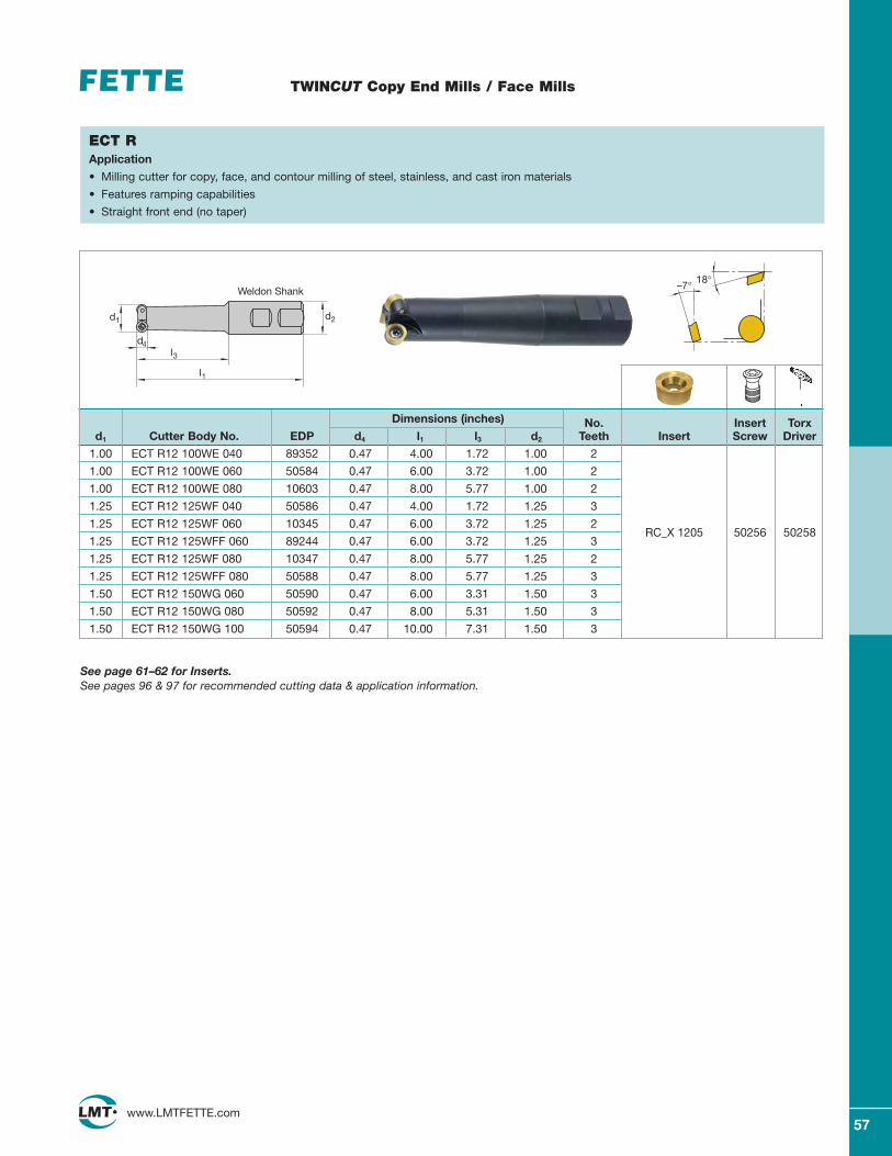
57www.LMTFETTE.com
TWINCUT Copy End Mills / Face Mills
ECT RApplication
• Milling cutter for copy, face, and contour milling of steel, stainless, and cast iron materials
• Features ramping capabilities
• Straight front end (no taper)
Dimensions (inches) No. Insert Torxd1 Cutter Body No. EDP d4 l1 l3 d2 Teeth Insert Screw Driver
1.00 ECT R12 100WE 040 89352 0.47 4.00 1.72 1.00 2
1.00 ECT R12 100WE 060 50584 0.47 6.00 3.72 1.00 2
1.00 ECT R12 100WE 080 10603 0.47 8.00 5.77 1.00 2
1.25 ECT R12 125WF 040 50586 0.47 4.00 1.72 1.25 3
1.25 ECT R12 125WF 060 10345 0.47 6.00 3.72 1.25 2
1.25 ECT R12 125WFF 060 89244 0.47 6.00 3.72 1.25 3RC_X 1205 50256 50258
1.25 ECT R12 125WF 080 10347 0.47 8.00 5.77 1.25 2
1.25 ECT R12 125WFF 080 50588 0.47 8.00 5.77 1.25 3
1.50 ECT R12 150WG 060 50590 0.47 6.00 3.31 1.50 3
1.50 ECT R12 150WG 080 50592 0.47 8.00 5.31 1.50 3
1.50 ECT R12 150WG 100 50594 0.47 10.00 7.31 1.50 3
–7° 18°
See page 61–62 for Inserts.See pages 96 & 97 for recommended cutting data & application information.
d1 d2
d4l3
l1
Weldon Shank
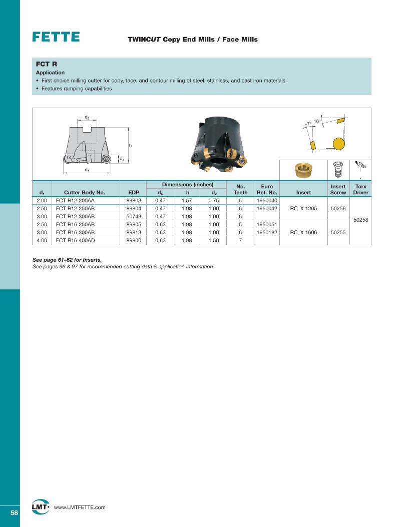
58www.LMTFETTE.com
TWINCUT Copy End Mills / Face Mills
FCT RApplication
• First choice milling cutter for copy, face, and contour milling of steel, stainless, and cast iron materials
• Features ramping capabilities
–7° 18°d2
d1
d4
h
Dimensions (inches) No. Euro Insert Torxd1 Cutter Body No. EDP d4 h d2 Teeth Ref. No. Insert Screw Driver
2.00 FCT R12 200AA 89803 0.47 1.57 0.75 5 1950040
2.50 FCT R12 250AB 89804 0.47 1.98 1.00 6 1950042 RC_X 1205 50256
3.00 FCT R12 300AB 50743 0.47 1.98 1.00 6
2.50 FCT R16 250AB 89805 0.63 1.98 1.00 5 195005150258
3.00 FCT R16 300AB 89813 0.63 1.98 1.00 6 1950182 RC_X 1606 50255
4.00 FCT R16 400AD 89800 0.63 1.98 1.50 7
See page 61–62 for Inserts.See pages 96 & 97 for recommended cutting data & application information.
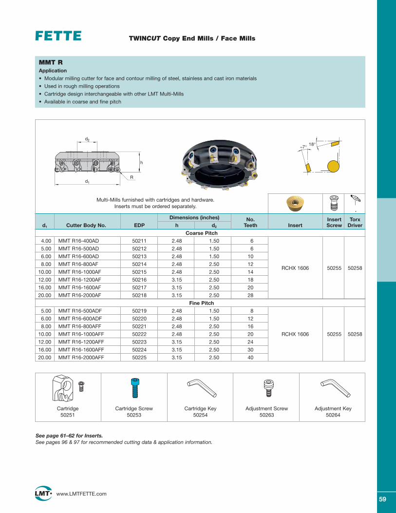
59www.LMTFETTE.com
TWINCUT Copy End Mills / Face Mills
Dimensions (inches) No. Insert Torxd1 Cutter Body No. EDP h d2 Teeth Insert Screw Driver
Coarse Pitch
4.00 MMT R16-400AD 50211 2.48 1.50 6
5.00 MMT R16-500AD 50212 2.48 1.50 6
6.00 MMT R16-600AD 50213 2.48 1.50 10
8.00 MMT R16-800AF 50214 2.48 2.50 12RCHX 1606
10.00 MMT R16-1000AF 50215 2.48 2.50 1450255 50258
12.00 MMT R16-1200AF 50216 3.15 2.50 18
16.00 MMT R16-1600AF 50217 3.15 2.50 20
20.00 MMT R16-2000AF 50218 3.15 2.50 28
Fine Pitch
5.00 MMT R16-500ADF 50219 2.48 1.50 8
6.00 MMT R16-600ADF 50220 2.48 1.50 12
8.00 MMT R16-800AFF 50221 2.48 2.50 16
10.00 MMT R16-1000AFF 50222 2.48 2.50 20 RCHX 1606 50255 50258
12.00 MMT R16-1200AFF 50223 3.15 2.50 24
16.00 MMT R16-1600AFF 50224 3.15 2.50 30
20.00 MMT R16-2000AFF 50225 3.15 2.50 40
–7° 18°
MMT RApplication
• Modular milling cutter for face and contour milling of steel, stainless and cast iron materials
• Used in rough milling operations
• Cartridge design interchangeable with other LMT Multi-Mills
• Available in coarse and fine pitch
Multi-Mills furnished with cartridges and hardware. Inserts must be ordered separately.
Cartridge50251
Cartridge Screw50253
Cartridge Key50254
Adjustment Screw50263
Adjustment Key50264
See page 61–62 for Inserts.See pages 96 & 97 for recommended cutting data & application information.
h
d1
R
d2
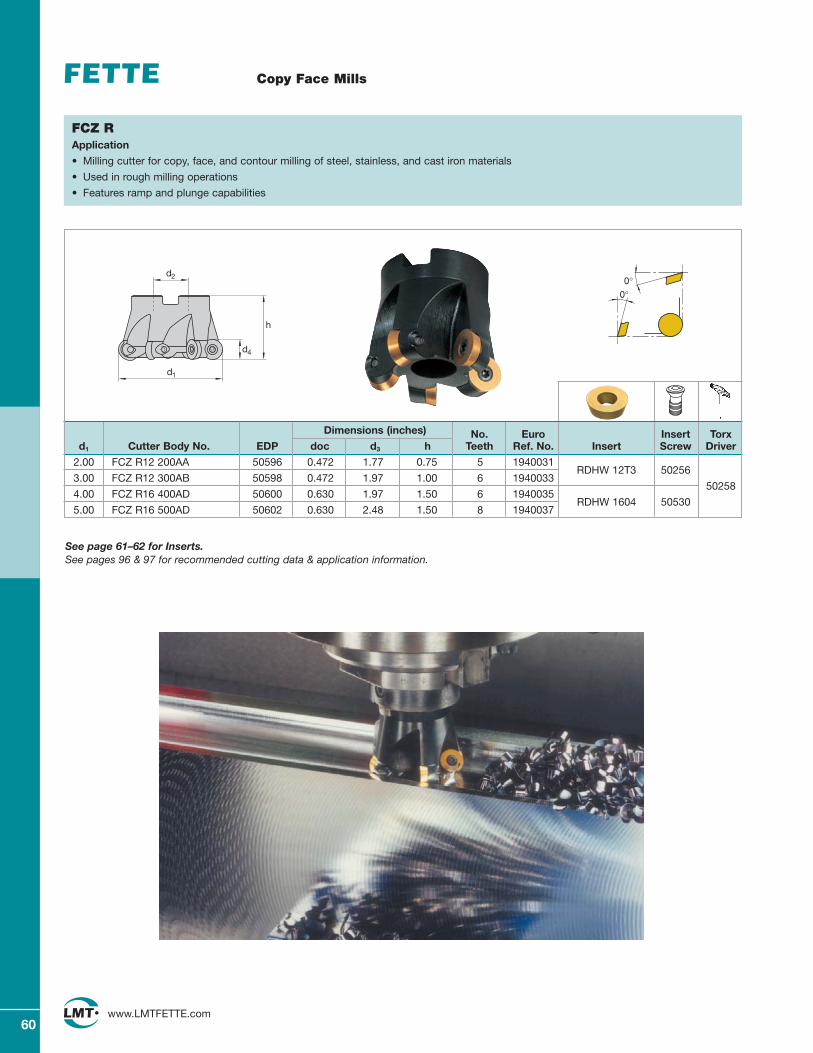
60www.LMTFETTE.com
Copy Face Mills
Dimensions (inches) No. Euro Insert Torxd1 Cutter Body No. EDP doc d3 h Teeth Ref. No. Insert Screw Driver
2.00 FCZ R12 200AA 50596 0.472 1.77 0.75 5 1940031RDHW 12T3
3.00 FCZ R12 300AB 50598 0.472 1.97 1.00 6 194003350256
4.00 FCZ R16 400AD 50600 0.630 1.97 1.50 6 1940035RDHW 1604
50258
5.00 FCZ R16 500AD 50602 0.630 2.48 1.50 8 194003750530
0°0°
FCZ RApplication
• Milling cutter for copy, face, and contour milling of steel, stainless, and cast iron materials
• Used in rough milling operations
• Features ramp and plunge capabilities
See page 61–62 for Inserts.See pages 96 & 97 for recommended cutting data & application information.
d2
d1
h
d4
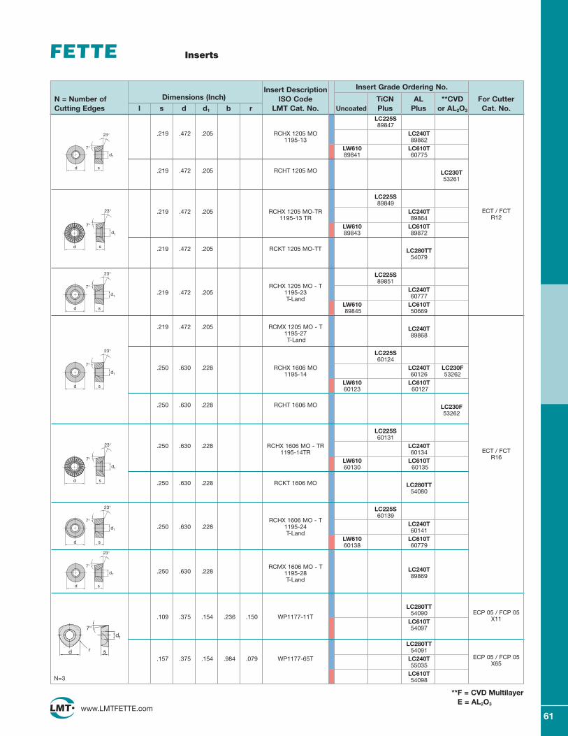
61www.LMTFETTE.com
Inserts
Insert Description Insert Grade Ordering No.
N = Number of Dimensions (Inch) ISO Code TiCN AL **CVD For CutterCutting Edges l s d d1 b r LMT Cat. No. Uncoated Plus Plus or AL2O3 Cat. No.
ECT / FCTR12
LC225S89847
.219 .472 .205 RCHX 1205 MO LC240T1195-13 89862
LW610 LC610T89841 60775
.219 .472 .205 RCHT 1205 MO LC230T53261
LC225S89849
.219 .472 .205 RCHX 1205 MO-TR LC240T1195-13 TR 89864
LW610 LC610T89843 89872
.219 .472 .205 RCKT 1205 MO-TT LC280TT54079
LC225S89851
RCHX 1205 MO - TLC240T.219 .472 .205 1195-2360777T-Land
LW610 LC610T89845 50669
.219 .472 .205 RCMX 1205 MO - T LC240T1195-27 89868T-Land
LC225S60124
.250 .630 .228 RCHX 1606 MO LC240T LC230F1195-14 60126 53262
LW610 LC610T60123 60127
.250 .630 .228 RCHT 1606 MO LC230F53262
LC225S60131
.250 .630 .228 RCHX 1606 MO - TR LC240T1195-14TR 60134
LW610 LC610T60130 60135
.250 .630 .228 RCKT 1606 MO LC280TT54080
LC225S60139
RCHX 1606 MO - TLC240T.250 .630 .228 1195-2460141T-Land
LW610 LC610T60138 60779
RCMX 1606 MO - T LC240T.250 .630 .228 1195-28 89869T-Land
LC280TT
.109 .375 .154 .236 .150 WP1177-11T54090
LC610T54097
LC280TT54091
.157 .375 .154 .984 .079 WP1177-65T LC240T55035
LC610TN=3 54098
d s
d1
7°
23°
d s
d1
7°
23°
d s
d1
7°
23°
d s
d1
7°
23°
d s
d1
7°
23°
d s
d1
7°
23°
ECT / FCTR16
**F = CVD MultilayerE = AL2O3
ECP 05 / FCP 05X65
sd r
d1
7°
d s
d1
7°
23°
ECP 05 / FCP 05X11
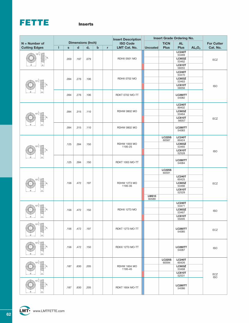
62www.LMTFETTE.com
Insert Description Insert Grade Ordering No.
N = Number of Dimensions (Inch) ISO Code TiCN AL For CutterCutting Edges l s d d1 b r LMT Cat. No. Uncoated Plus Plus AL2O3 Cat. No.
ECZ
LC240T53469
.059 .197 .079 RDHX 0501 MO LC603Z53462
LC610T56055
LC240T53470
.094 .276 .106 RDHX 0702 MO LC603Z53463
LC610T56056
.094 .276 .106 RDKT 0702 MO-TT LC280TT54082
LC240T89402
.094 .315 .110 RDHW 0802 MO LC603Z53464
LC610T56057
.094 .315 .110 RDHW 0802 MO LC280TT54083
LC225S LC240T60587 60424
.125 .394 .150 RDHW 1003 MO LC603Z1195-25 53465
LC610T52528
.125 .394 .150 RDKT 1003 MO-TTLC280TT
54084
LC225S60591
LC240T60425
.156 .472 .197 RDHW 12T3 MO LC603Z1195-35 53466
LC610T52529
LW61060589
LC240T53471
.156 .472 .150 RDHX 12T3 MO LC603Z53467
LC610T55005
.156 .472 .197 RDKT 12T3 MO-TT LC280TT54085
.156 .472 .150 RDKX 12T3 MO-TT LC280TT54087
LC225S LC240T60594 60426
.187 .630 .205 RDHW 1604 MO LC603Z1195-45 53468
LC610T52531
.187 .630 .205 RDKT 1604 MO-TTLC280TT
54086
s
15°
d1
d
s
15°
d1
d
s
15°
d1
d
s
15°
d1
d
Inserts
s
15°
d1
d
ISO
ECZ
ISO
ECZ
ECZ
ISO
ISO
ECZISO
s
15°
d1
d
s
15°
d1
d
s
15°
d1
d
s
15°
d1
d
s
15°
d1
d
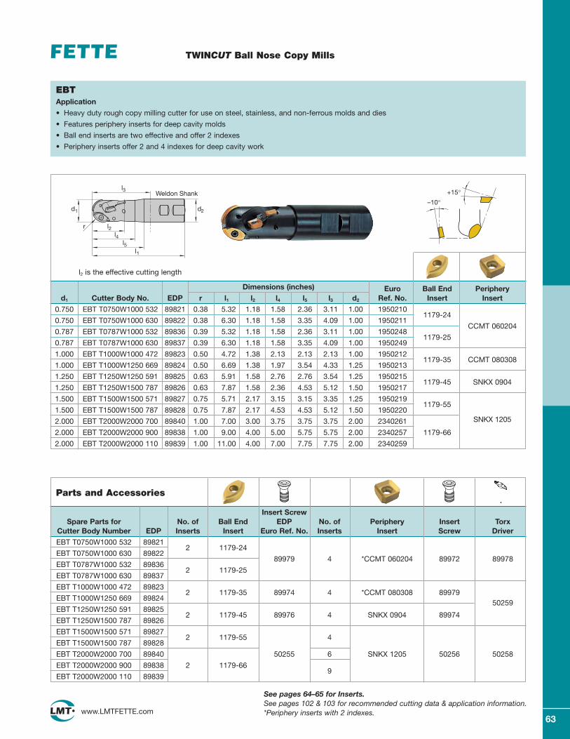
63www.LMTFETTE.com
TWINCUT Ball Nose Copy Mills
EBTApplication
• Heavy duty rough copy milling cutter for use on steel, stainless, and non-ferrous molds and dies
• Features periphery inserts for deep cavity molds
• Ball end inserts are two effective and offer 2 indexes
• Periphery inserts offer 2 and 4 indexes for deep cavity work
l2 is the effective cutting length
Dimensions (inches) Euro Ball End Peripheryd1 Cutter Body No. EDP r l1 l2 l4 l5 l3 d2 Ref. No. Insert Insert
0.750 EBT T0750W1000 532 89821 0.38 5.32 1.18 1.58 2.36 3.11 1.00 1950210
0.750 EBT T0750W1000 630 89822 0.38 6.30 1.18 1.58 3.35 4.09 1.00 19502111179-24
CCMT 0602040.787 EBT T0787W1000 532 89836 0.39 5.32 1.18 1.58 2.36 3.11 1.00 1950248
0.787 EBT T0787W1000 630 89837 0.39 6.30 1.18 1.58 3.35 4.09 1.00 19502491179-25
1.000 EBT T1000W1000 472 89823 0.50 4.72 1.38 2.13 2.13 2.13 1.00 1950212CCMT 080308
1.000 EBT T1000W1250 669 89824 0.50 6.69 1.38 1.97 3.54 4.33 1.25 19502131179-35
1.250 EBT T1250W1250 591 89825 0.63 5.91 1.58 2.76 2.76 3.54 1.25 1950215SNKX 0904
1.250 EBT T1250W1500 787 89826 0.63 7.87 1.58 2.36 4.53 5.12 1.50 19502171179-45
1.500 EBT T1500W1500 571 89827 0.75 5.71 2.17 3.15 3.15 3.35 1.25 1950219
1.500 EBT T1500W1500 787 89828 0.75 7.87 2.17 4.53 4.53 5.12 1.50 19502201179-55
2.000 EBT T2000W2000 700 89840 1.00 7.00 3.00 3.75 3.75 3.75 2.00 2340261 SNKX 1205
2.000 EBT T2000W2000 900 89838 1.00 9.00 4.00 5.00 5.75 5.75 2.00 2340257 1179-66
2.000 EBT T2000W2000 110 89839 1.00 11.00 4.00 7.00 7.75 7.75 2.00 2340259
–10°+15°
Insert ScrewSpare Parts for No. of Ball End EDP No. of Periphery Insert Torx
Cutter Body Number EDP Inserts Insert Euro Ref. No. Inserts Insert Screw Driver
EBT T0750W1000 532 89821
EBT T0750W1000 630 898222 1179-24
*CCMT 060204 EBT T0787W1000 532 89836
89979 4 89972 89978
EBT T0787W1000 630 898372 1179-25
EBT T1000W1000 472 89823*CCMT 080308
EBT T1000W1250 669 898242 1179-35 89974 4 89979
50259EBT T1250W1250 591 89825
SNKX 0904EBT T1250W1500 787 89826
2 1179-45 89976 4 89974
EBT T1500W1500 571 89827
EBT T1500W1500 787 898282 1179-55 4
EBT T2000W2000 700 89840 50255 6 SNKX 1205 50256 50258
EBT T2000W2000 900 89838 2 1179-669
EBT T2000W2000 110 89839
See pages 64–65 for Inserts.See pages 102 & 103 for recommended cutting data & application information.*Periphery inserts with 2 indexes.
Parts and Accessories
d1
r
l1
l2l4
l5
Weldon Shank
d2
l3
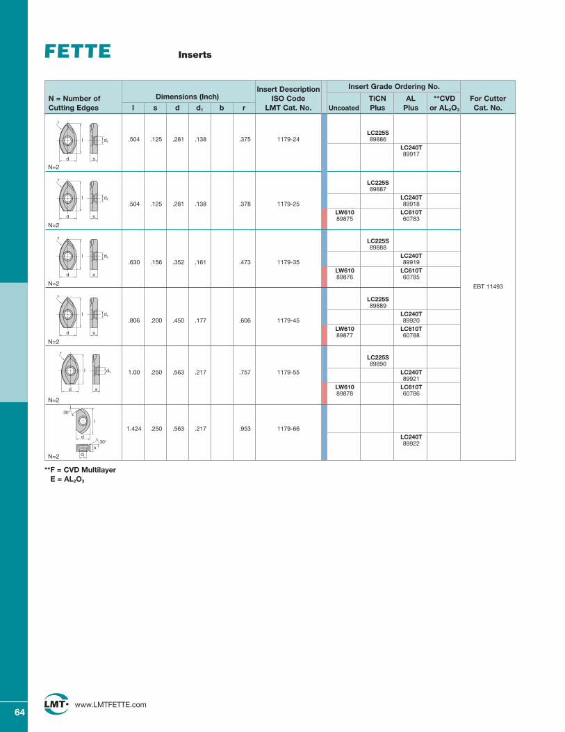
64www.LMTFETTE.com
Inserts
Insert Description Insert Grade Ordering No.
N = Number of Dimensions (Inch) ISO Code TiCN AL **CVD For CutterCutting Edges l s d d1 b r LMT Cat. No. Uncoated Plus Plus or AL2O3 Cat. No.
EBT 11493
LC225S.504 .125 .281 .138 .375 1179-24 89886
LC240T89917
N=2
LC225S89887
LC240T.504 .125 .281 .138 .378 1179-25 89918
LW610 LC610T89875 60783
N=2
LC225S89888
LC240T.630 .156 .352 .161 .473 1179-35 89919
LW610 LC610T89876 60785
N=2
LC225S89889
LC240T.806 .200 .450 .177 .606 1179-45 89920
LW610 LC610T89877 60788
N=2
LC225S89890
1.00 .250 .563 .217 .757 1179-55 LC240T89921
LW610 LC610T89878 60786
N=2
1.424 .250 .563 .217 .953 1179-66LC240T89922
N=2
s
d1
r
l
d
s
d1
r
l
d
s
d1
r
l
d
s
d1
r
l
d
**F = CVD MultilayerE = AL2O3
s
d1
r
l
d
d
l
30°
30°
d1
s
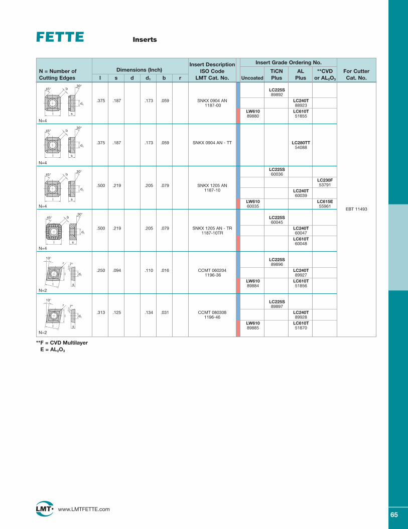
65www.LMTFETTE.com
Insert Description Insert Grade Ordering No.
N = Number of Dimensions (Inch) ISO Code TiCN AL **CVD For CutterCutting Edges l s d d1 b r LMT Cat. No. Uncoated Plus Plus or AL2O3 Cat. No.
EBT 11493
LC225S89892
.375 .187 .173 .059 SNKX 0904 AN LC240T1187-00 88923
LW610 LC610T89880 51855
N=4
.375 .187 .173 .059 SNKX 0904 AN - TT LC280TT54088
N=4
LC225S60036
LC230F.500 .219 .205 .079 SNKX 1205 AN 53791
1187-10 LC240T60039
LW610 LC615EN=4 60035 55961
LC225S60045
.500 .219 .205 .079 SNKX 1205 AN - TR LC240T1187-10TR 60047
LC610T60048
N=4
LC225S89896
.250 .094 .110 .016 CCMT 060204 LC240T1196-36 89927
LW610 LC610T89884 51856
N=2
LC225S89897
.313 .125 .134 .031 CCMT 080308 LC240T1196-46 89928
LW610 LC610T89885 51870
N=2
b
l s
d1
30°45°
Inserts
**F = CVD MultilayerE = AL2O3
b
s
d1
30°
l
45°
b
l s
d1
30°45°
s
7°
10°
l
l
d1
r
s
7°
10°
l
l
d1
r
b
l s
d1
30°45°
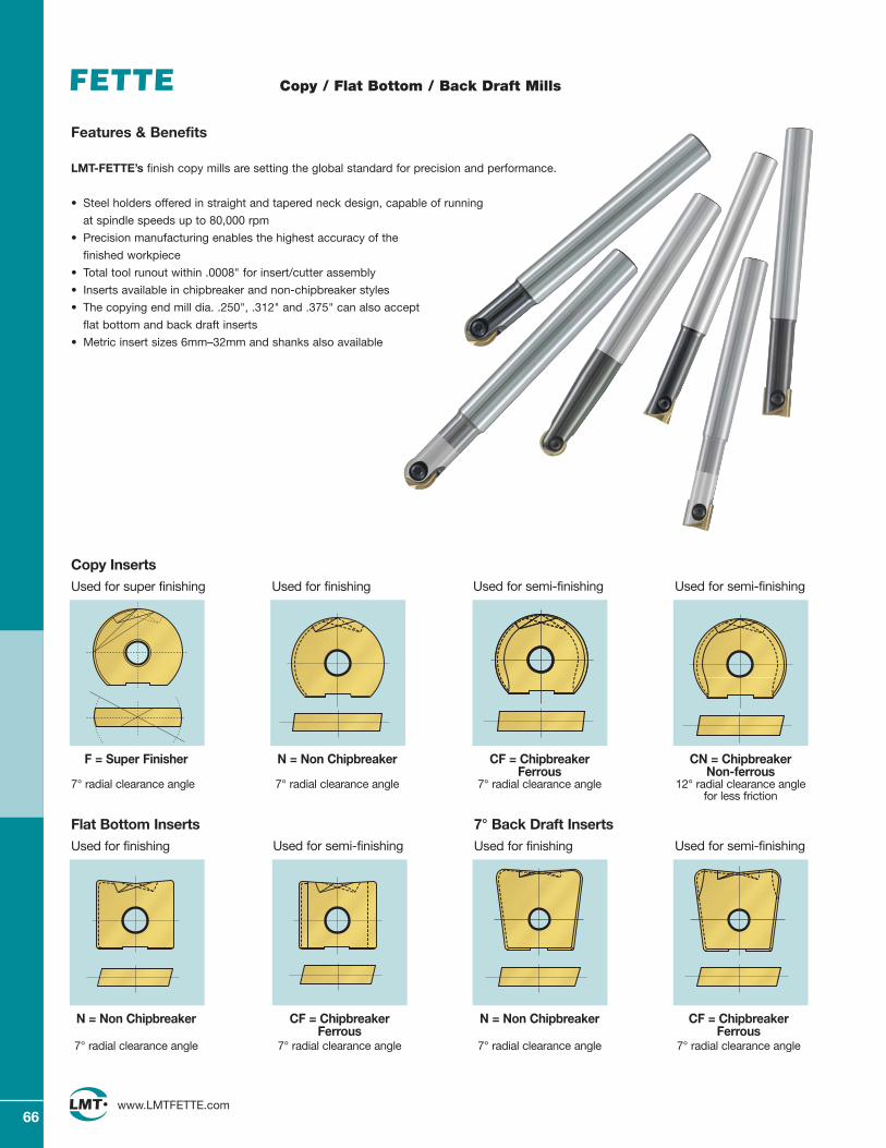
66www.LMTFETTE.com
Copy / Flat Bottom / Back Draft Mills
Features & Benefits
LMT-FETTE’s finish copy mills are setting the global standard for precision and performance.
• Steel holders offered in straight and tapered neck design, capable of running
at spindle speeds up to 80,000 rpm
• Precision manufacturing enables the highest accuracy of the
finished workpiece
• Total tool runout within .0008" for insert/cutter assembly
• Inserts available in chipbreaker and non-chipbreaker styles
• The copying end mill dia. .250", .312" and .375" can also accept
flat bottom and back draft inserts
• Metric insert sizes 6mm–32mm and shanks also available
N = Non Chipbreaker CF = Chipbreaker CN = Chipbreaker Ferrous Non-ferrous
7° radial clearance angle 7° radial clearance angle 12° radial clearance anglefor less friction
Used for semi-finishing Used for semi-finishingUsed for finishing
Copy Inserts
N = Non Chipbreaker CF = Chipbreaker N = Non Chipbreaker CF = ChipbreakerFerrous Ferrous
7° radial clearance angle 7° radial clearance angle 7° radial clearance angle 7° radial clearance angle
Used for semi-finishingUsed for finishing
Flat Bottom InsertsUsed for semi-finishingUsed for finishing
7° Back Draft Inserts
F = Super Finisher
7° radial clearance angle
Used for super finishing
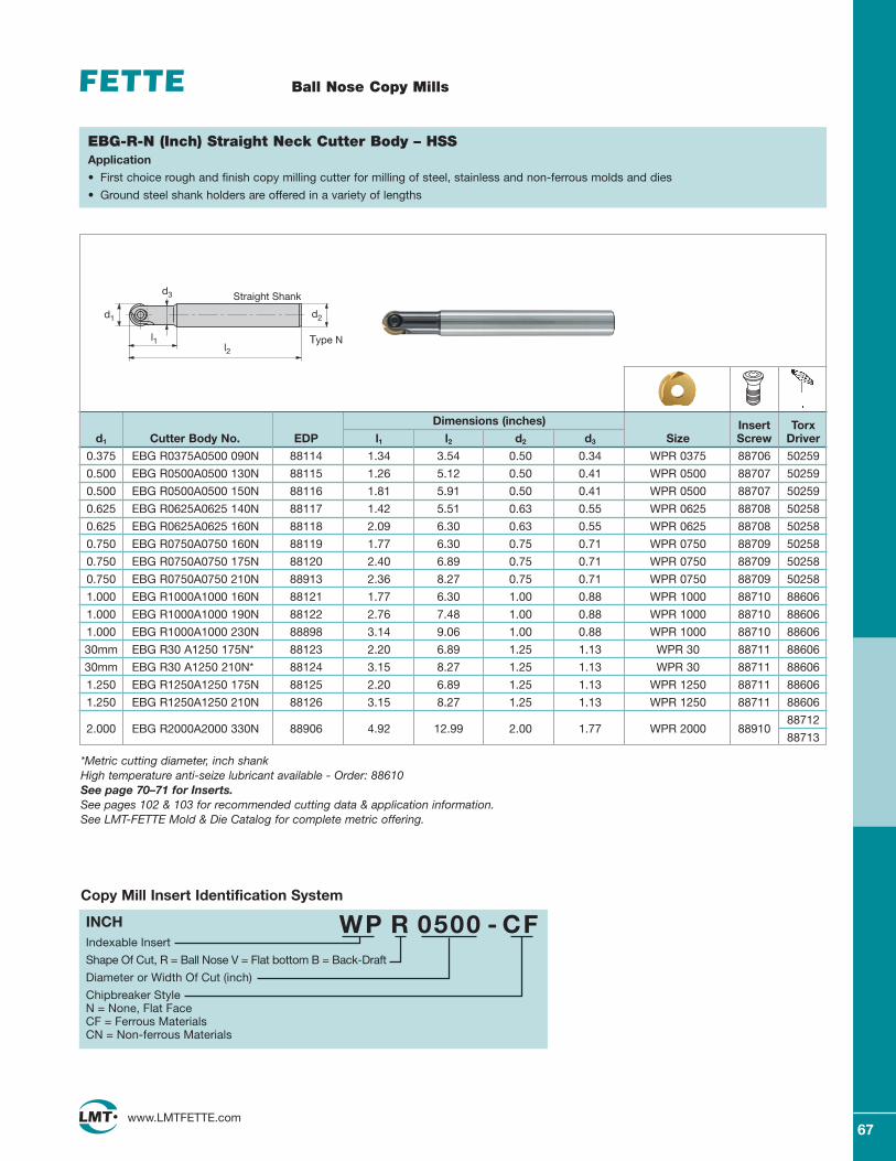
67www.LMTFETTE.com
Ball Nose Copy Mills
Dimensions (inches) Insert Torxd1 Cutter Body No. EDP l1 l2 d2 d3 Size Screw Driver
0.375 EBG R0375A0500 090N 88114 1.34 3.54 0.50 0.34 WPR 0375 88706 50259
0.500 EBG R0500A0500 130N 88115 1.26 5.12 0.50 0.41 WPR 0500 88707 50259
0.500 EBG R0500A0500 150N 88116 1.81 5.91 0.50 0.41 WPR 0500 88707 50259
0.625 EBG R0625A0625 140N 88117 1.42 5.51 0.63 0.55 WPR 0625 88708 50258
0.625 EBG R0625A0625 160N 88118 2.09 6.30 0.63 0.55 WPR 0625 88708 50258
0.750 EBG R0750A0750 160N 88119 1.77 6.30 0.75 0.71 WPR 0750 88709 50258
0.750 EBG R0750A0750 175N 88120 2.40 6.89 0.75 0.71 WPR 0750 88709 50258
0.750 EBG R0750A0750 210N 88913 2.36 8.27 0.75 0.71 WPR 0750 88709 50258
1.000 EBG R1000A1000 160N 88121 1.77 6.30 1.00 0.88 WPR 1000 88710 88606
1.000 EBG R1000A1000 190N 88122 2.76 7.48 1.00 0.88 WPR 1000 88710 88606
1.000 EBG R1000A1000 230N 88898 3.14 9.06 1.00 0.88 WPR 1000 88710 88606
30mm EBG R30 A1250 175N* 88123 2.20 6.89 1.25 1.13 WPR 30 88711 88606
30mm EBG R30 A1250 210N* 88124 3.15 8.27 1.25 1.13 WPR 30 88711 88606
1.250 EBG R1250A1250 175N 88125 2.20 6.89 1.25 1.13 WPR 1250 88711 88606
1.250 EBG R1250A1250 210N 88126 3.15 8.27 1.25 1.13 WPR 1250 88711 88606
2.000 EBG R2000A2000 330N 88906 4.92 12.99 2.00 1.77 WPR 2000 8891088712
88713
EBG-R-N (Inch) Straight Neck Cutter Body – HSSApplication
• First choice rough and finish copy milling cutter for milling of steel, stainless and non-ferrous molds and dies
• Ground steel shank holders are offered in a variety of lengths
*Metric cutting diameter, inch shankHigh temperature anti-seize lubricant available - Order: 88610See page 70–71 for Inserts.See pages 102 & 103 for recommended cutting data & application information.See LMT-FETTE Mold & Die Catalog for complete metric offering.
Indexable Insert
Shape Of Cut, R = Ball Nose V = Flat bottom B = Back-Draft
Diameter or Width Of Cut (inch)
Chipbreaker StyleN = None, Flat FaceCF = Ferrous MaterialsCN = Non-ferrous Materials
WP R 0500 - CFINCH
Copy Mill Insert Identification System
d1
d3
l1l2
d2
Straight Shank
Type N
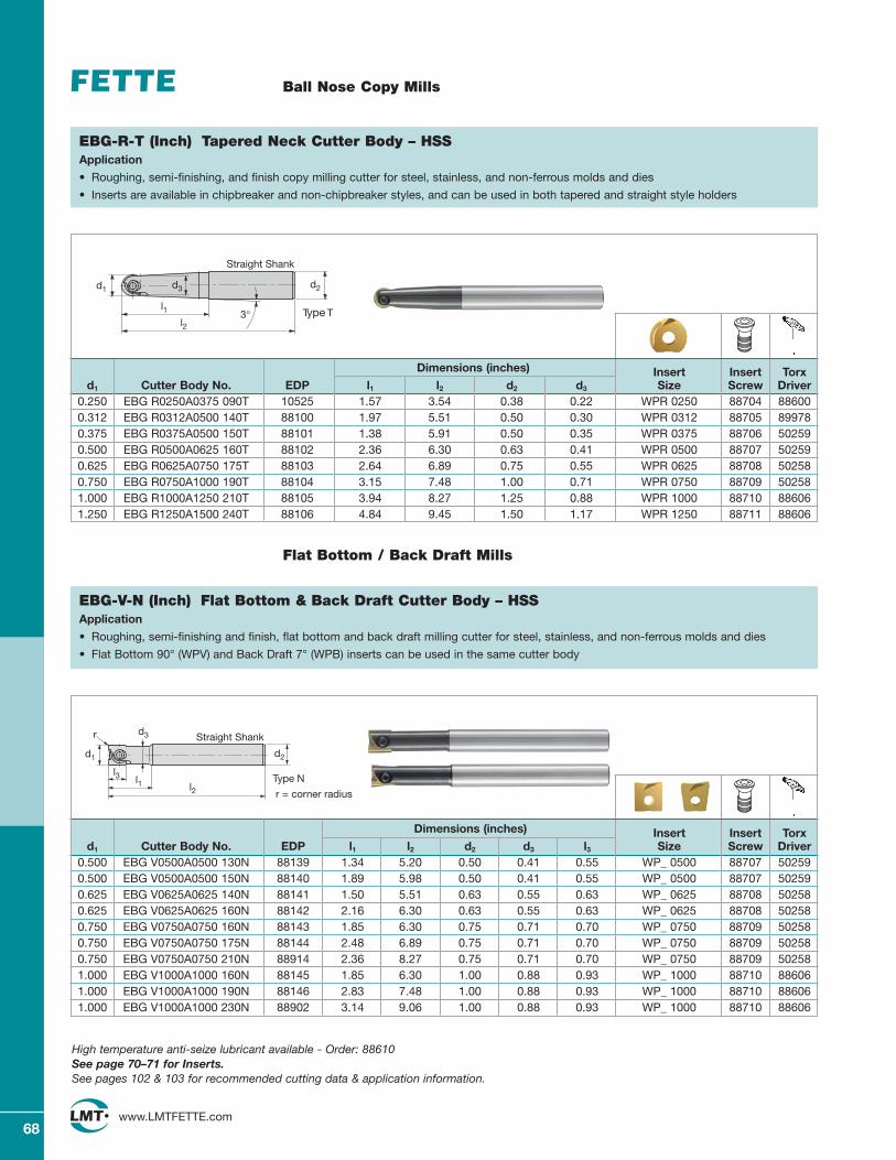
68www.LMTFETTE.com
Ball Nose Copy Mills
Dimensions (inches) Insert Insert Torxd1 Cutter Body No. EDP l1 l2 d2 d3 Size Screw Driver
0.250 EBG R0250A0375 090T 10525 1.57 3.54 0.38 0.22 WPR 0250 88704 886000.312 EBG R0312A0500 140T 88100 1.97 5.51 0.50 0.30 WPR 0312 88705 899780.375 EBG R0375A0500 150T 88101 1.38 5.91 0.50 0.35 WPR 0375 88706 502590.500 EBG R0500A0625 160T 88102 2.36 6.30 0.63 0.41 WPR 0500 88707 502590.625 EBG R0625A0750 175T 88103 2.64 6.89 0.75 0.55 WPR 0625 88708 502580.750 EBG R0750A1000 190T 88104 3.15 7.48 1.00 0.71 WPR 0750 88709 502581.000 EBG R1000A1250 210T 88105 3.94 8.27 1.25 0.88 WPR 1000 88710 886061.250 EBG R1250A1500 240T 88106 4.84 9.45 1.50 1.17 WPR 1250 88711 88606
EBG-R-T (Inch) Tapered Neck Cutter Body – HSSApplication
• Roughing, semi-finishing, and finish copy milling cutter for steel, stainless, and non-ferrous molds and dies
• Inserts are available in chipbreaker and non-chipbreaker styles, and can be used in both tapered and straight style holders
Dimensions (inches) Insert Insert Torxd1 Cutter Body No. EDP l1 l2 d2 d3 l3 Size Screw Driver
0.500 EBG V0500A0500 130N 88139 1.34 5.20 0.50 0.41 0.55 WP_ 0500 88707 502590.500 EBG V0500A0500 150N 88140 1.89 5.98 0.50 0.41 0.55 WP_ 0500 88707 502590.625 EBG V0625A0625 140N 88141 1.50 5.51 0.63 0.55 0.63 WP_ 0625 88708 502580.625 EBG V0625A0625 160N 88142 2.16 6.30 0.63 0.55 0.63 WP_ 0625 88708 502580.750 EBG V0750A0750 160N 88143 1.85 6.30 0.75 0.71 0.70 WP_ 0750 88709 502580.750 EBG V0750A0750 175N 88144 2.48 6.89 0.75 0.71 0.70 WP_ 0750 88709 502580.750 EBG V0750A0750 210N 88914 2.36 8.27 0.75 0.71 0.70 WP_ 0750 88709 502581.000 EBG V1000A1000 160N 88145 1.85 6.30 1.00 0.88 0.93 WP_ 1000 88710 886061.000 EBG V1000A1000 190N 88146 2.83 7.48 1.00 0.88 0.93 WP_ 1000 88710 886061.000 EBG V1000A1000 230N 88902 3.14 9.06 1.00 0.88 0.93 WP_ 1000 88710 88606
EBG-V-N (Inch) Flat Bottom & Back Draft Cutter Body – HSSApplication
• Roughing, semi-finishing and finish, flat bottom and back draft milling cutter for steel, stainless, and non-ferrous molds and dies
• Flat Bottom 90° (WPV) and Back Draft 7° (WPB) inserts can be used in the same cutter body
Flat Bottom / Back Draft Mills
r = corner radius
High temperature anti-seize lubricant available - Order: 88610See page 70–71 for Inserts.See pages 102 & 103 for recommended cutting data & application information.
d1 d3
l1l2
d2
3°
Straight Shank
Type T
d1
d3
l1 l2
d2
Straight Shank
l3
r
Type N
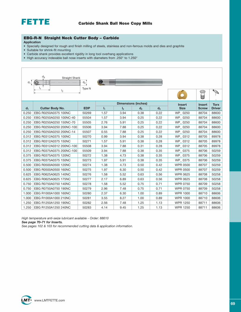
69www.LMTFETTE.com
Carbide Shank Ball Nose Copy Mills
Dimensions (inches) Insert Insert Torxd1 Cutter Body No. EDP l1 l2 d2 d3 Size Screw Driver
0.250 EBG R0250A0375 100NC 50269 1.57 3.94 0.38 0.22 WP_ 0250 88704 88600
0.250 EBG R0250A0250 100NC-40 55504 1.57 3.94 0.25 0.22 WP_ 0250 88704 88600
0.250 EBG R0250A0250 150NC-70 55505 2.76 5.91 0.25 0.22 WP_ 0250 88704 88600
0.250 EBG R0250A0250 200NC-100 55506 3.94 7.88 0.25 0.22 WP_ 0250 88704 88600
0.250 EBG R0250A0250 200NC-14 55507 0.55 7.88 0.25 0.22 WP_ 0250 88704 88600
0.312 EBG R0312A0375 100NC 50270 0.99 3.94 0.38 0.28 WP_ 0312 88705 89978
0.312 EBG R0312A0375 150NC 50271 1.57 5.91 0.38 0.28 WP_ 0312 88705 89978
0.312 EBG R0312A0312 200NC-100 55508 3.94 7.88 0.31 0.28 WP_ 0312 88705 89978
0.312 EBG R0375A0375 200NC-100 55509 3.94 7.88 0.38 0.35 WP_ 0375 88706 50259
0.375 EBG R0375A0375 120NC 50272 1.38 4.73 0.38 0.35 WP_ 0375 88706 50259
0.375 EBG R0375A0375 150NC 50273 1.97 5.91 0.38 0.35 WP_ 0375 88706 50259
0.500 EBG R0500A0500 120NC 50274 1.38 4.73 0.50 0.42 WPR 0500 88707 50259
0.500 EBG R0500A0500 160NC 50275 1.97 6.30 0.50 0.42 WPR 0500 88707 50259
0.625 EBG R0625A0625 140NC 50276 1.58 5.52 0.63 0.56 WPR 0625 88708 50258
0.625 EBG R0625A0625 175NC 50277 2.17 6.89 0.63 0.56 WPR 0625 88708 50258
0.750 EBG R0750A0750 140NC 50278 1.58 5.52 0.75 0.71 WPR 0750 88709 50258
0.750 EBG R0750A0750 190NC 50279 2.96 7.48 0.75 0.71 WPR 0750 88709 50258
1.000 EBG R1000A1000 160NC 50280 2.37 6.30 1.00 0.89 WPR 1000 88710 88606
1.000 EBG R1000A1000 210NC 50281 3.55 8.27 1.00 0.89 WPR 1000 88710 88606
1.250 EBG R1250A1250 190NC 50282 2.56 7.48 1.25 1.13 WPR 1250 88711 88606
1.250 EBG R1250A1250 240NC 50283 4.14 9.45 1.25 1.13 WPR 1250 88711 88606
EBG-R-N Straight Neck Cutter Body – CarbideApplication• Specially designed for rough and finish milling of steels, stainless and non-ferrous molds and dies and graphite• Suitable for shrink-fit mounting• Carbide shank provides excellent rigidity in long tool overhang applications• High accuracy indexable ball nose inserts with diameters from .250" to 1.250"
High temperature anti-seize lubricant available - Order: 88610See page 70–71 for Inserts.See pages 102 & 103 for recommended cutting data & application information.
d1
d3
l1l2
d2
Straight Shank
Type N
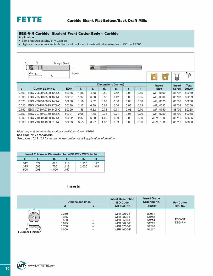
70www.LMTFETTE.com
Insert Description Insert Grade Dimensions (Inch) ISO Code Ordering No. For Cutter
d s LMT Cat. No. LC610T Cat. No.
0.250 – WPR 0250-F 899810.375 – WPR 0375-F 512130.500 – WPR 0500-F 512140.625 – WPR 0625-F 512150.750 – WPR 0750-F 512161.000 – WPR 1000-F 51217
F=Super Finisher
Inserts
ds
d
EBG-RTEBG-RN
Carbide Shank Flat Bottom/Back Draft Mills
Dimensions (inches) Insert Insert Torxd1 Cutter Body No. EDP l1 l2 d2 d3 r l Size Screw Driver
0.500 EBG V0500A0500 120NC 50286 1.38 4.73 0.50 0.42 0.03 0.55 WP_ 0500 88707 50259
0.500 EBG V0500A0500 160NC 50287 1.97 6.30 0.50 0.42 0.03 0.55 WP_ 0500 88707 50259
0.625 EBG V0625A0625 140NC 50288 1.58 5.52 0.63 0.56 0.03 0.63 WP_ 0625 88708 50258
0.625 EBG V0625A0625 175NC 50289 2.17 6.89 0.63 0.56 0.03 0.63 WP_ 0625 88708 50258
0.750 EBG V0750A0750 140NC 50290 1.58 5.52 0.75 0.71 0.06 0.70 WP_ 0750 88709 50258
0.750 EBG V0750A0750 190NC 50291 2.96 7.48 0.75 0.71 0.06 0.70 WP_ 0750 88709 50258
1.000 EBG V1000A1000 160NC 50292 2.37 6.30 1.00 0.89 0.06 0.93 WPV_ 1000 88710 88606
1.000 EBG V1000A1000 210NC 50293 3.55 8.27 1.00 0.89 0.06 0.93 WPV_ 1000 88710 88606
EBG-V-N Carbide Straight Front Cutter Body – CarbideApplication• Same features as EBG-R-V-Carbide• High accuracy indexable flat bottom and back draft inserts with diameters from .250" to 1.250"
High temperature anti-seize lubricant available - Order: 88610See page 70–71 for Inserts.See pages 102 & 103 for recommended cutting data & application information.
d1
d3
l1 l2
d2
Straight Shank
l3
r
Type N
Insert Thickness Dimension for WPR WPV WPB (inch)
d1 s d1 s d1 s
.312 .079 .625 .118 1.250 .197
.375 .098 .750 .118 2.000 .315
.500 .098 1.000 .157
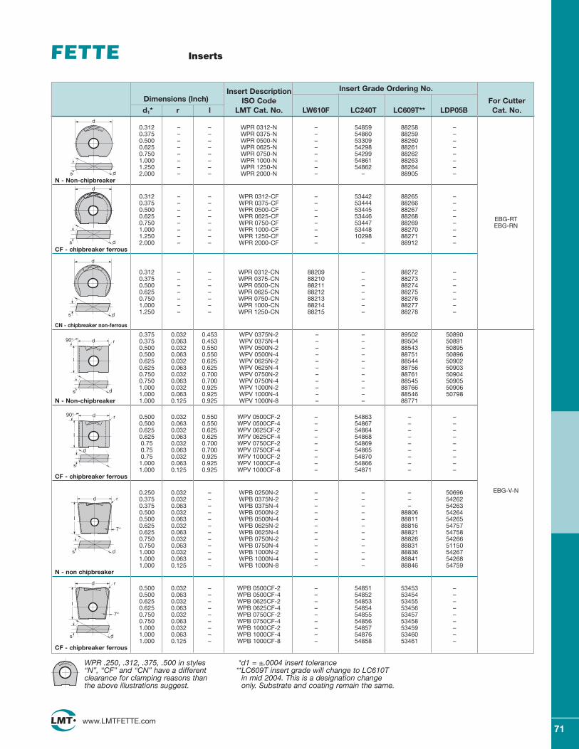
71www.LMTFETTE.com
0.312 – – WPR 0312-N – 54859 88258 –0.375 – – WPR 0375-N – 54860 88259 –0.500 – – WPR 0500-N – 53309 88260 –0.625 – – WPR 0625-N – 54298 88261 –0.750 – – WPR 0750-N – 54299 88262 –1.000 – – WPR 1000-N – 54861 88263 –1.250 – – WPR 1250-N – 54862 88264 –2.000 – – WPR 2000-N – – 88905 –
N - Non-chipbreaker
0.312 – – WPR 0312-CF – 53442 88265 –0.375 – – WPR 0375-CF – 53444 88266 –0.500 – – WPR 0500-CF – 53445 88267 –0.625 – – WPR 0625-CF – 53446 88268 –0.750 – – WPR 0750-CF – 53447 88269 –1.000 – – WPR 1000-CF – 53448 88270 –1.250 – – WPR 1250-CF – 10298 88271 –2.000 – – WPR 2000-CF – – 88912 –
CF - chipbreaker ferrous
0.312 – – WPR 0312-CN 88209 – 88272 –0.375 – – WPR 0375-CN 88210 – 88273 –0.500 – – WPR 0500-CN 88211 – 88274 –0.625 – – WPR 0625-CN 88212 – 88275 –0.750 – – WPR 0750-CN 88213 – 88276 –1.000 – – WPR 1000-CN 88214 – 88277 –1.250 – – WPR 1250-CN 88215 – 88278 –
CN - chipbreaker non-ferrous
0.375 0.032 0.453 WPV 0375N-2 – – 89502 508900.375 0.063 0.453 WPV 0375N-4 – – 89504 508910.500 0.032 0.550 WPV 0500N-2 – – 88543 508950.500 0.063 0.550 WPV 0500N-4 – – 88751 508960.625 0.032 0.625 WPV 0625N-2 – – 88544 509020.625 0.063 0.625 WPV 0625N-4 – – 88756 509030.750 0.032 0.700 WPV 0750N-2 – – 88761 509040.750 0.063 0.700 WPV 0750N-4 – – 88545 509051.000 0.032 0.925 WPV 1000N-2 – – 88766 509061.000 0.063 0.925 WPV 1000N-4 – – 88546 50798
N - Non-chipbreaker 1.000 0.125 0.925 WPV 1000N-8 – – 88771
0.500 0.032 0.550 WPV 0500CF-2 – 54863 – –0.500 0.063 0.550 WPV 0500CF-4 – 54867 – –0.625 0.032 0.625 WPV 0625CF-2 – 54864 – –0.625 0.063 0.625 WPV 0625CF-4 – 54868 – –0.75 0.032 0.700 WPV 0750CF-2 – 54869 – –0.75 0.063 0.700 WPV 0750CF-4 – 54865 – –0.75 0.032 0.925 WPV 1000CF-2 – 54870 – –
1.000 0.063 0.925 WPV 1000CF-4 – 54866 – –1.000 0.125 0.925 WPV 1000CF-8 – 54871 – –
CF - chipbreaker ferrous
0.250 0.032 – WPB 0250N-2 – – – 506960.375 0.032 – WPB 0375N-2 – – – 542620.375 0.063 – WPB 0375N-4 – – – 542630.500 0.032 – WPB 0500N-2 – – 88806 542640.500 0.063 – WPB 0500N-4 – – 88811 542650.625 0.032 – WPB 0625N-2 – – 88816 547570.625 0.063 – WPB 0625N-4 – – 88821 547580.750 0.032 – WPB 0750N-2 – – 88826 542660.750 0.063 – WPB 0750N-4 – – 88831 511501.000 0.032 – WPB 1000N-2 – – 88836 542671.000 0.063 – WPB 1000N-4 – – 88841 542681.000 0.125 – WPB 1000N-8 – – 88846 54759
N - non chipbreaker
0.500 0.032 – WPB 0500CF-2 – 54851 53453 –0.500 0.063 – WPB 0500CF-4 – 54852 53454 –0.625 0.032 – WPB 0625CF-2 – 54853 53455 –0.625 0.063 – WPB 0625CF-4 – 54854 53456 –0.750 0.032 – WPB 0750CF-2 – 54855 53457 –0.750 0.063 – WPB 0750CF-4 – 54856 53458 –1.000 0.032 – WPB 1000CF-2 – 54857 53459 –1.000 0.063 – WPB 1000CF-4 – 54876 53460 –1.000 0.125 – WPB 1000CF-8 – 54858 53461 –
CF - chipbreaker ferrous
Inserts
Insert Description Insert Grade Ordering No.Dimensions (Inch) ISO Code For Cutterd1* r l LMT Cat. No. LW610F LC240T LC609T** LDP05B Cat. No.
EBG-RTEBG-RN
EBG-V-N
WPR .250, .312, .375, .500 in styles“N”, “CF” and “CN” have a differentclearance for clamping reasons thanthe above illustrations suggest.
*d1 = ±.0004 insert tolerance**LC609T insert grade will change to LC610T
in mid 2004. This is a designation changeonly. Substrate and coating remain the same.
d
ds
d
ds
d
ds
d r
l
ds
90°
d r
l
d
s
90°
d r
l
ds
7°
d r
l
ds
7°
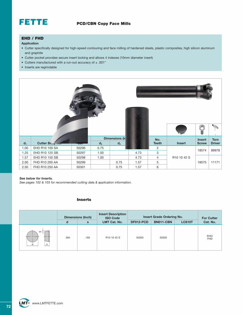
72www.LMTFETTE.com
PCD/CBN Copy Face Mills
Dimensions (inches) No. Insert Torxd1 Cutter Body No. EDP d2 d4 l1 / h Teeth Insert Screw Driver
1.00 EHD R10 100 SA 50296 0.75 3.94 218574 89978
1.25 EHD R10 125 SB 50297 1.00 4.73 3
1.57 EHD R10 150 SB 50298 1.00 4.73 4 R10 10 42 S
2.00 FHD R10 200 AA 50299 0.75 1.57 5 18575 11171
2.50 FHD R10 250 AA 50301 0.75 1.57 6
EHD / FHDApplication
• Cutter specifically designed for high-speed contouring and face milling of hardened steels, plastic composites, high silicon aluminum
and graphite
• Cutter pocket provides secure insert locking and allows 4 indexes (10mm diameter insert)
• Cutters manufactured with a run-out accuracy of ± .001"
• Inserts are regrindable
See below for Inserts.See pages 102 & 103 for recommended cutting data & application information.
Insert DescriptionDimensions (Inch) ISO Code Insert Grade Ordering No. For Cutter
d s LMT Cat. No. DF012-PCD BN011-CBN LC610T Cat. No.
EHD/FHD.394 .165 R10 10 42 S 50303 50305
Inserts
d s
11°
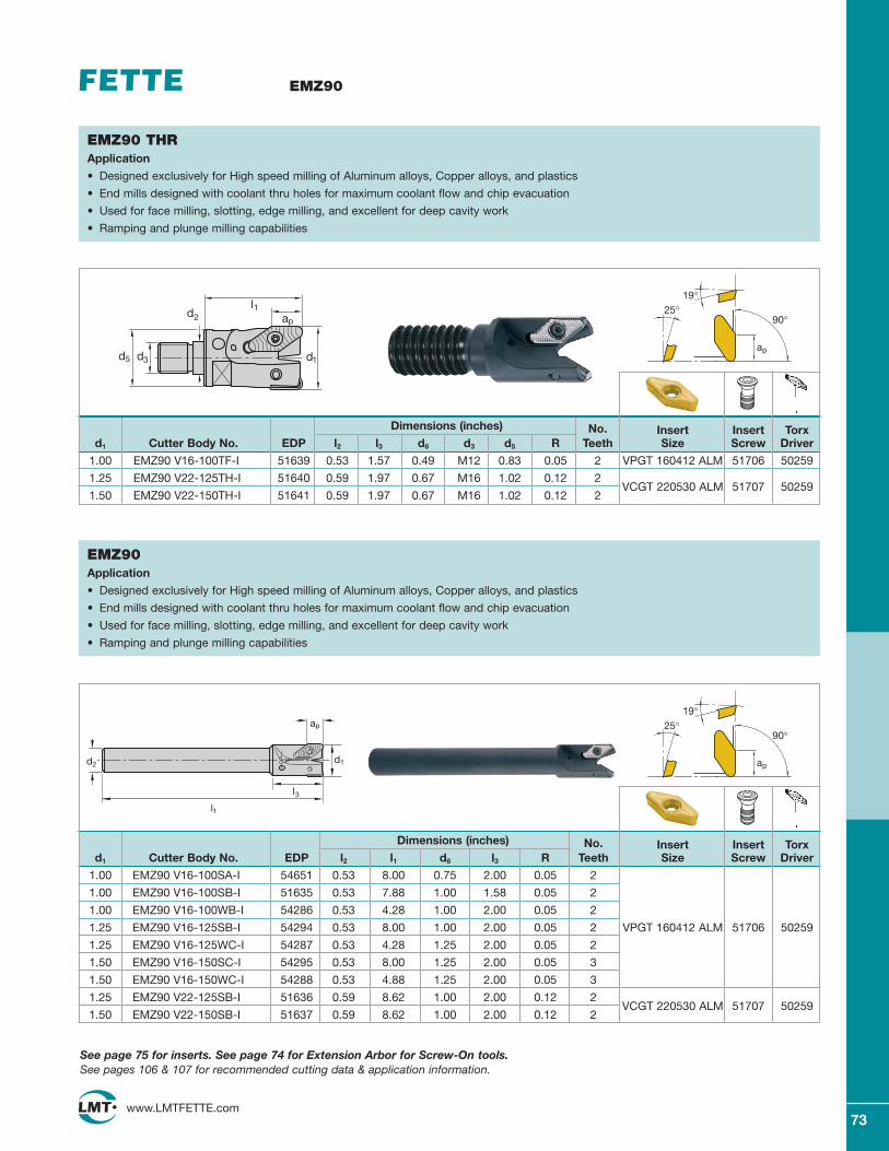
73www.LMTFETTE.com
EMZ90
EMZ90 THRApplication
• Designed exclusively for High speed milling of Aluminum alloys, Copper alloys, and plastics
• End mills designed with coolant thru holes for maximum coolant flow and chip evacuation
• Used for face milling, slotting, edge milling, and excellent for deep cavity work
• Ramping and plunge milling capabilities
EMZ90 Application
• Designed exclusively for High speed milling of Aluminum alloys, Copper alloys, and plastics
• End mills designed with coolant thru holes for maximum coolant flow and chip evacuation
• Used for face milling, slotting, edge milling, and excellent for deep cavity work
• Ramping and plunge milling capabilities
See page 75 for inserts. See page 74 for Extension Arbor for Screw-On tools.See pages 106 & 107 for recommended cutting data & application information.
Dimensions (inches) No. Insert Insert Torxd1 Cutter Body No. EDP l2 l3 d6 d3 d5 R Teeth Size Screw Driver
1.00 EMZ90 V16-100TF-I 51639 0.53 1.57 0.49 M12 0.83 0.05 2 VPGT 160412 ALM 51706 50259
1.25 EMZ90 V22-125TH-I 51640 0.59 1.97 0.67 M16 1.02 0.12 2VCGT 220530 ALM 51707 50259
1.50 EMZ90 V22-150TH-I 51641 0.59 1.97 0.67 M16 1.02 0.12 2
90°
ap
25°19°
l1ap
d1
d2
d5 d3
Dimensions (inches) No. Insert Insert Torxd1 Cutter Body No. EDP l2 l1 d6 l3 R Teeth Size Screw Driver
1.00 EMZ90 V16-100SA-I 54651 0.53 8.00 0.75 2.00 0.05 2
1.00 EMZ90 V16-100SB-I 51635 0.53 7.88 1.00 1.58 0.05 2
1.00 EMZ90 V16-100WB-I 54286 0.53 4.28 1.00 2.00 0.05 2
1.25 EMZ90 V16-125SB-I 54294 0.53 8.00 1.00 2.00 0.05 2 VPGT 160412 ALM 51706 50259
1.25 EMZ90 V16-125WC-I 54287 0.53 4.28 1.25 2.00 0.05 2
1.50 EMZ90 V16-150SC-I 54295 0.53 8.00 1.25 2.00 0.05 3
1.50 EMZ90 V16-150WC-I 54288 0.53 4.88 1.25 2.00 0.05 3
1.25 EMZ90 V22-125SB-I 51636 0.59 8.62 1.00 2.00 0.12 2VCGT 220530 ALM 51707 50259
1.50 EMZ90 V22-150SB-I 51637 0.59 8.62 1.00 2.00 0.12 2
90°
ap
25°19°
l1
d2
l3
d1
ap
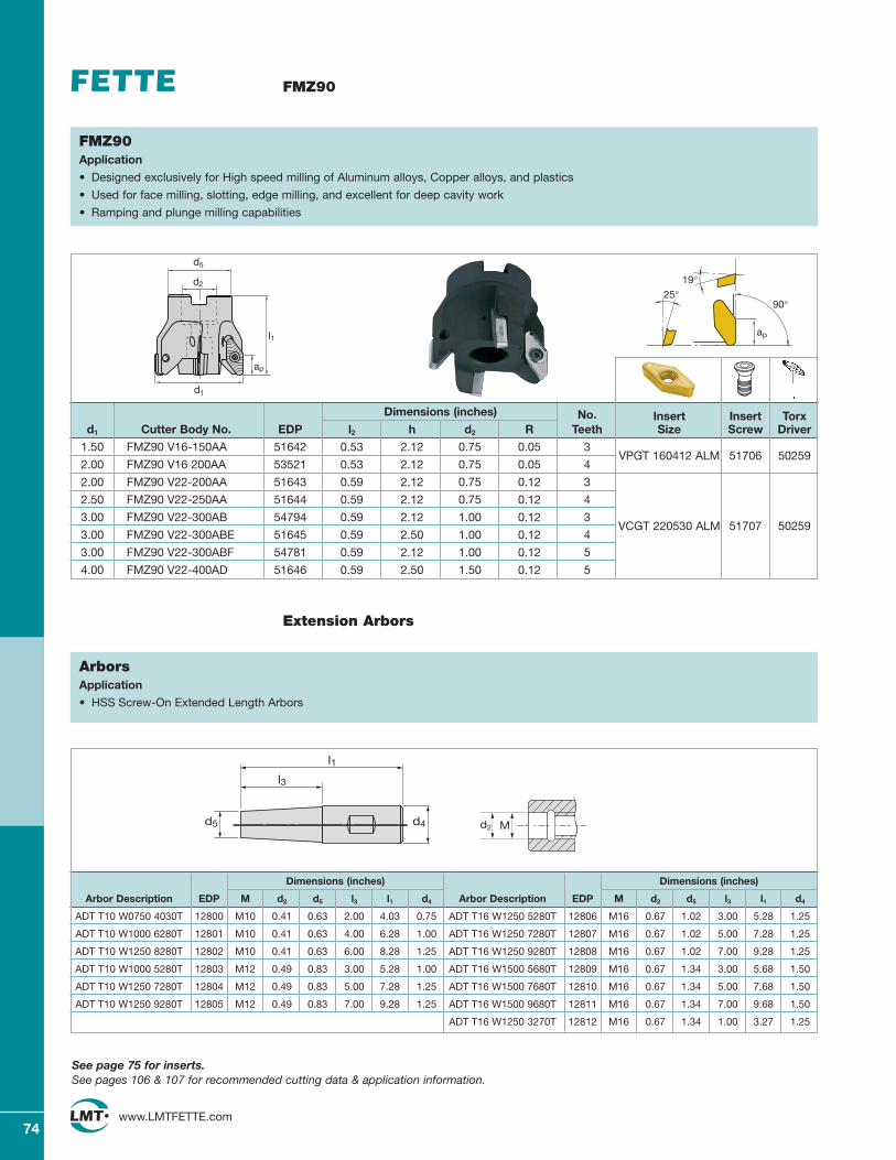
74www.LMTFETTE.com
FMZ90
FMZ90 Application
• Designed exclusively for High speed milling of Aluminum alloys, Copper alloys, and plastics
• Used for face milling, slotting, edge milling, and excellent for deep cavity work
• Ramping and plunge milling capabilities
Extension Arbors
Dimensions (inches)
Arbor Description EDP M d2 d5 l3 l1 d4
ADT T10 W0750 4030T 12800 M10 0.41 0.63 2.00 4.03 0.75
ADT T10 W1000 6280T 12801 M10 0.41 0.63 4.00 6.28 1.00
ADT T10 W1250 8280T 12802 M10 0.41 0.63 6.00 8.28 1.25
ADT T10 W1000 5280T 12803 M12 0.49 0.83 3.00 5.28 1.00
ADT T10 W1250 7280T 12804 M12 0.49 0.83 5.00 7.28 1.25
ADT T10 W1250 9280T 12805 M12 0.49 0.83 7.00 9.28 1.25
ArborsApplication
• HSS Screw-On Extended Length Arbors
Dimensions (inches)
Arbor Description EDP M d2 d5 l3 l1 d4
ADT T16 W1250 5280T 12806 M16 0.67 1.02 3.00 5.28 1.25
ADT T16 W1250 7280T 12807 M16 0.67 1.02 5.00 7.28 1.25
ADT T16 W1250 9280T 12808 M16 0.67 1.02 7.00 9.28 1.25
ADT T16 W1500 5680T 12809 M16 0.67 1.34 3.00 5.68 1.50
ADT T16 W1500 7680T 12810 M16 0.67 1.34 5.00 7.68 1.50
ADT T16 W1500 9680T 12811 M16 0.67 1.34 7.00 9.68 1.50
ADT T16 W1250 3270T 12812 M16 0.67 1.34 1.00 3.27 1.25
d4
l3
d5
l1
See page 75 for inserts.See pages 106 & 107 for recommended cutting data & application information.
Dimensions (inches) No. Insert Insert Torxd1 Cutter Body No. EDP l2 h d2 R Teeth Size Screw Driver
1.50 FMZ90 V16-150AA 51642 0.53 2.12 0.75 0.05 3VPGT 160412 ALM 51706 50259
2.00 FMZ90 V16 200AA 53521 0.53 2.12 0.75 0.05 4
2.00 FMZ90 V22-200AA 51643 0.59 2.12 0.75 0.12 3
2.50 FMZ90 V22-250AA 51644 0.59 2.12 0.75 0.12 4
3.00 FMZ90 V22-300AB 54794 0.59 2.12 1.00 0.12 3VCGT 220530 ALM 51707 50259
3.00 FMZ90 V22-300ABE 51645 0.59 2.50 1.00 0.12 4
3.00 FMZ90 V22-300ABF 54781 0.59 2.12 1.00 0.12 5
4.00 FMZ90 V22-400AD 51646 0.59 2.50 1.50 0.12 5
90°
ap
25°19°
d5
d2
ap
l1
d1
d2 M
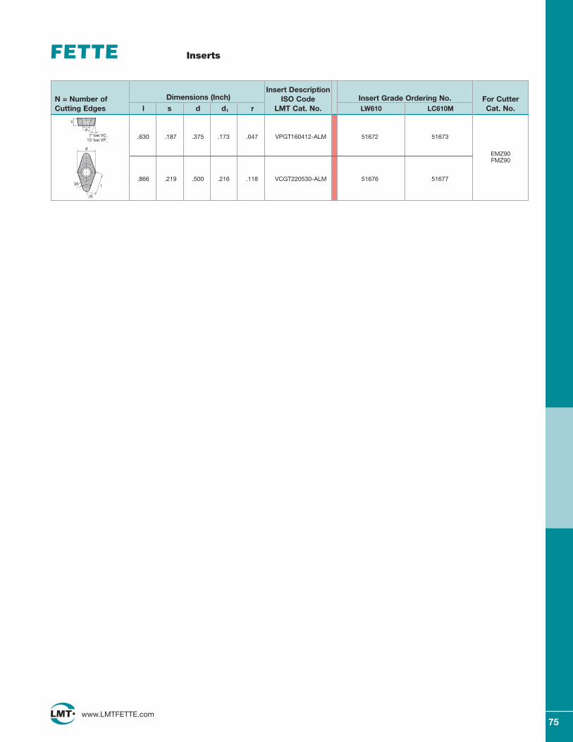
75www.LMTFETTE.com
Inserts
Insert DescriptionN = Number of Dimensions (Inch) ISO Code Insert Grade Ordering No. For CutterCutting Edges l s d d1 r LMT Cat. No. LW610 LC610M Cat. No.
EMZ90FMZ90
.630 .187 .375 .173 .047 VPGT160412-ALM 51672 51673
.866 .219 .500 .216 .118 VCGT220530-ALM 51676 51677
d
35° l
R
s
d1
7° bei VC_ 15° bei VP_
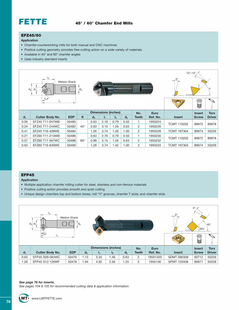
76www.LMTFETTE.com
45° / 60° Chamfer End Mills
Dimensions (inches) No. Euro Insert Torxd1 Cutter Body No. EDP K d3 l1 l3 d2 Teeth Ref. No. Insert Screw Driver
0.05 EFZ45 T11-047WB 50480 0.63 2.16 0.79 0.50 1 1950224TCMT 110202
0.24 EFZ45 T11-244WC 50482 45° 0.83 3.15 1.26 0.63 2 195022689972 89978
0.41 EFZ45 T16-409WE 50484 1.26 3.74 1.26 1.00 2 1950228 TCMT 16T304 89974 50259
0.21 EFZ60 T11-213WB 50486 0.63 2.76 0.79 0.50 1 1950230TCMT 110202
0.57 EFZ60 T11-567WC 50488 60° 0.98 3.15 1.26 0.63 2 195023289972 89978
0.63 EFZ60 T16-630WE 50490 1.26 3.74 1.42 1.00 2 1950233 TCMT 16T304 89974 50259
0°
12°–15°
κ
EFZ45/60Application
• Chamfer-countersinking mills for both manual and CNC machines
• Positive cutting geometry provides free-cutting action on a wide variety of materials
• Available in 45° and 60° chamfer angles
• Uses industry standard inserts
d3 d1 d2
l1κ
l3Weldon Shank
Dimensions (inches) No. Euro Insert Torxd1 Cutter Body No. EDP d3 l1 l3 d2 Teeth Ref. No. Insert Screw Driver
0.63 EFP45 S09-063WC 50476 1.13 3.35 1.46 0.63 2 1950135S SDMT 090308 60712 50259
1.26 EFP45 S12-126WF 50478 1.94 4.92 2.56 1.25 3 1950136 SPMT 120408 89971 50258
45°
0°
0°
doc
EFP45Application
• Multiple application chamfer milling cutter for steel, stainless and non-ferrous materials
• Positive cutting action provides smooth and quiet cutting
• Unique design chamfers top and bottom bores; mill “V” grooves; chamfer T slots; and chamfer slots
See page 78 for inserts.See pages 104 & 105 for recommended cutting data & application information.
d2d1d3
l3
l145°
Weldon Shank
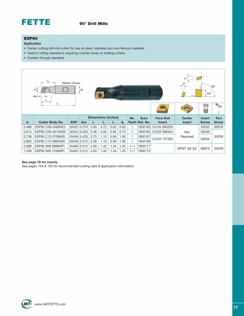
77www.LMTFETTE.com
90° Drill Mills
Dimensions (inches) No. Euro Face End Center Insert Torxd1 Cutter Body No. EDP doc l1 l3 l4 d2 Teeth Ref. No. Insert Insert Screw Driver
0.488 ESP90 C08-0488WCI 50452 0.276 3.00 0.75 0.65 0.63 1 1950183 CCHX 080203 50532 89978
0.613 ESP90 C09-0613WDI 50454 0.335 3.38 0.95 0.95 0.75 1 1950185 CCHX 090304 Not 50546
0.738 ESP90 C12-0738WEI 50456 0.433 3.75 1.10 0.99 1.00 1 1950167CCHX 12T305
Required 50259
0.863 ESP90 C12-0863WEI 50458 0.512 3.38 1.10 0.99 1.00 1 195016950534
0.988 ESP90 X09 0988WFI 50460 0.512 4.00 1.42 1.34 1.25 1+1 1950171SPMT 3(2.5)2
1.238 ESP90 X09 1238WFI 50462 0.512 4.00 1.42 1.34 1.25 1+1 195017389973 50259
90°
doc
0°
5°
ESP90Application
• Center cutting drill-mill cutter for use on steel, stainless and non-ferrous materials
• Used in milling operations requiring counter bores or slotting cutters
• Coolant through standard
See page 78 for inserts.See pages 104 & 105 for recommended cutting data & application information.
d1 d2
doc
l3
l4l1
Weldon Shank
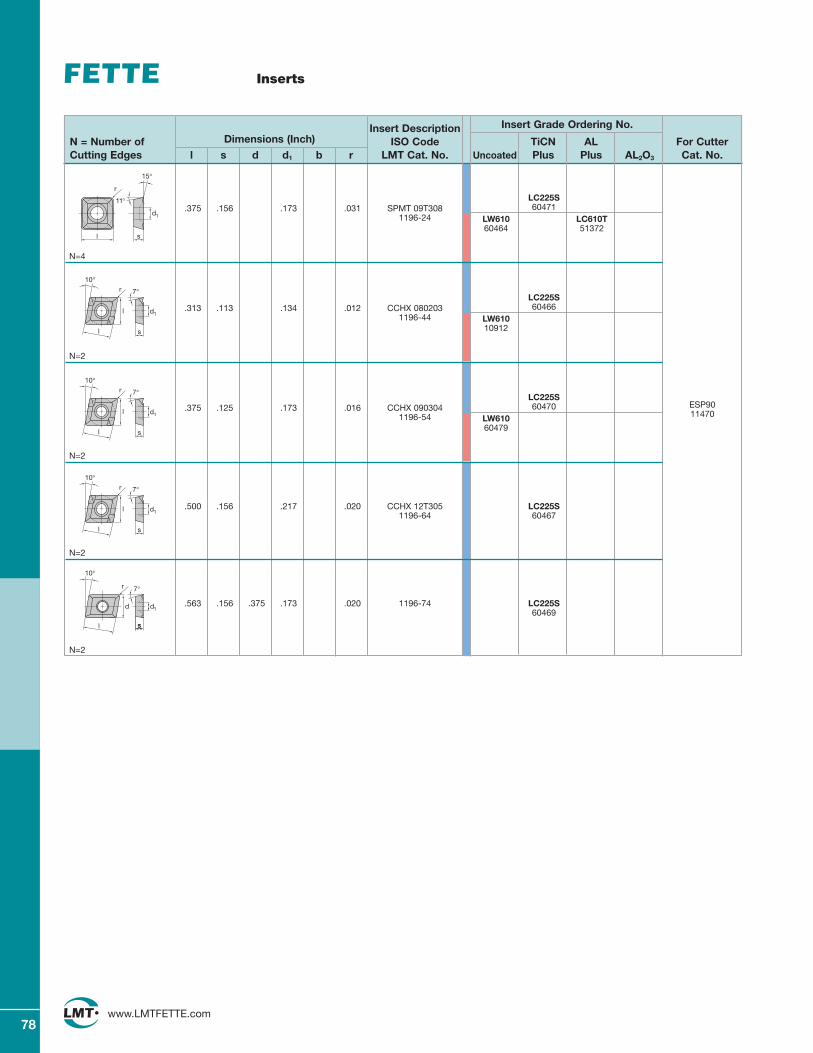
78www.LMTFETTE.com
Inserts
Insert Description Insert Grade Ordering No.
N = Number of Dimensions (Inch) ISO Code TiCN AL For CutterCutting Edges l s d d1 b r LMT Cat. No. Uncoated Plus Plus AL2O3 Cat. No.
ESP9011470
LC225S.375 .156 .173 .031 SPMT 09T308 60471
1196-24 LW610 LC610T60464 51372
N=4
LC225S.313 .113 .134 .012 CCHX 080203 60466
1196-44 LW61010912
N=2
LC225S.375 .125 .173 .016 CCHX 090304 60470
1196-54 LW61060479
N=2
.500 .156 .217 .020 CCHX 12T305 LC225S1196-64 60467
N=2
.563 .156 .375 .173 .020 1196-74 LC225S60469
N=2
s
d1
l
r
11°
15°
s
7°
10°
l
l
d1
r
s
7°
10°
l
l
d1
r
s
7°
10°
l
l
d1
r
s
7°
10°
d d1
sl
r
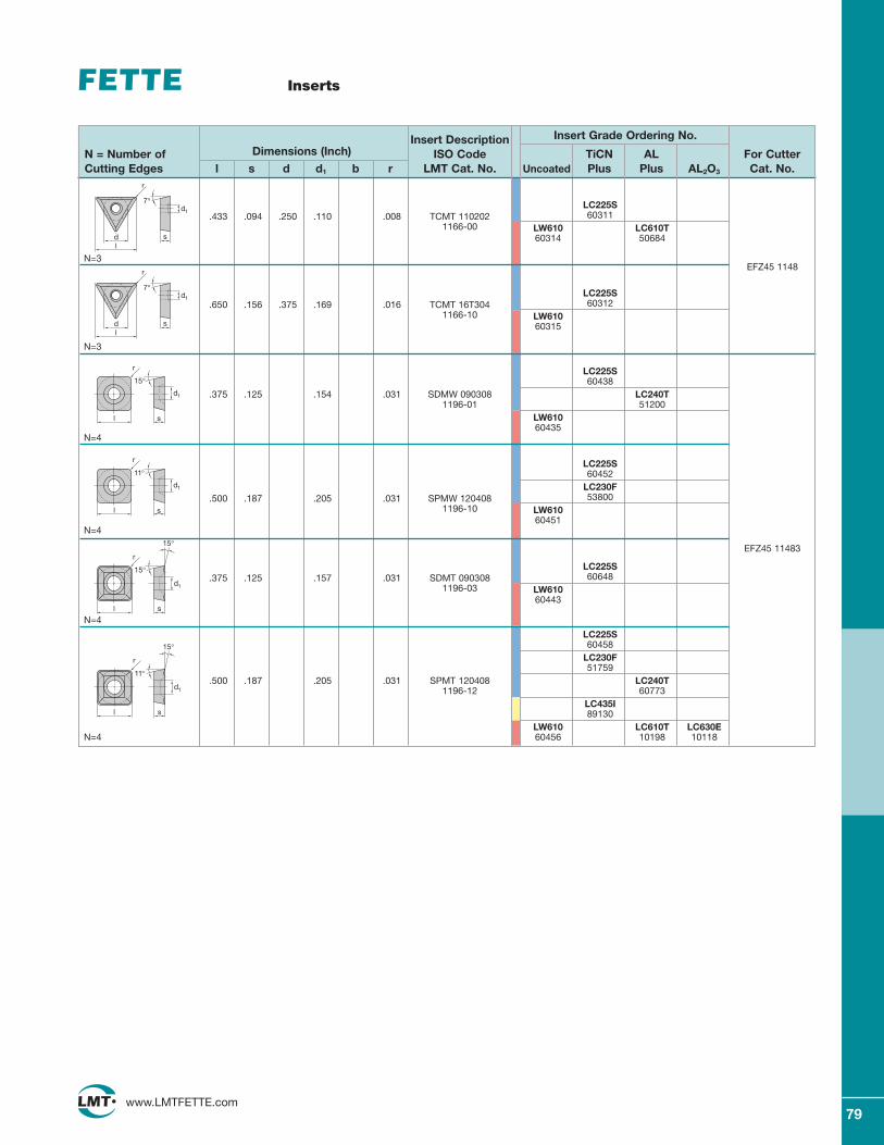
79www.LMTFETTE.com
Inserts
Insert Description Insert Grade Ordering No.
N = Number of Dimensions (Inch) ISO Code TiCN AL For CutterCutting Edges l s d d1 b r LMT Cat. No. Uncoated Plus Plus AL2O3 Cat. No.
LC225S.433 .094 .250 .110 .008 TCMT 110202 60311
1166-00 LW610 LC610T60314 50684
N=3
LC225S.650 .156 .375 .169 .016 TCMT 16T304 60312
1166-10 LW61060315
N=3
LC225S60438
.375 .125 .154 .031 SDMW 090308 LC240T1196-01 51200
LW61060435
N=4
LC225S60452
LC230F.500 .187 .205 .031 SPMW 120408 53800
1196-10 LW61060451
N=4
LC225S60648.375 .125 .157 .031 SDMT 090308
LW6101196-0360443
N=4
LC225S60458
LC230F51759
.500 .187 .205 .031 SPMT 120408 LC240T1196-12 60773
LC435I89130
LW610 LC610T LC630EN=4 60456 10198 10118
EFZ45 1148
EFZ45 11483
r
d sl
7°d1
r
d sl
7°d1
r
s
d1
15°
l
r
s
d1
11°
l
s
d1
l
r
15°
15°
s
d1
l
r
11°
15°
80www.LMTFETTE.com
Technical Section Table of Contents
Technical Section 80
Parts and Accessories 81
ISO Insert Designation 82–83
LMT Insert Grades 84
Insert Grade Designation 85
Recommended Maximum Feed per Tooth (fZ) for inserts LC280TT 86
Cutting Data Recommendations for LC240T 87
Cutting Data Recommendations for LC230F 88
Cutting Data Recommendations for LC225T, LC225S 89
Cutting Data Recommendations for LC444W 90
Cutting Data Recommendations for LC430T, LC440T 90
Cutting Data Recommendations for LC610T 91
Cutting Data Recommendations for LC615E 92
Look to LMT-FETTE for all your precision metalworking needs 93
Cutting Data Recommendations for Face Mills – TwinCut / ISO 94
Application Data for Face Mills 95
Ramping with TWINCUT 45° and UNIVEX 95
Cutting Data Recommendations for Copy Mills 96
Application Data for FCT45 and MCT45 Face Mill 97
Cutting Data Recommendations for TWINCUT Vario 98
Application Data for Universal Milling TWINCUT VARIO 99
Cutting Data Recommendations for TWINCUT Feed Mill ECP05/FCP05 100
Application Data for TWINCUT Feed Mill ECP05/FCP05 101
Cutting Data Recommendations for Ball Nose, and Flat Bottom / Back Draft End Mills 102
Feed, Speed, and Diameter Compensation for 3 Axis Milling 103
Cutting Data Recommendations for UNIVEX Face Mills, End Mills, Helical Mills, and Chamfering Cutters 104
Application Data for End Mill, Face Mill and Helical Mill 105
Cutting Data Recommendations for EMZ90 / FMZ90 106
Recommended Maximum Feed per Tooth (fZ) for Inserts 106
Application Data for EMZ90 / FMZ90 107
Application Data for End Mill, Face Mill, and Helical Mill 108
Formulas 109
Modular Milling Cutters (Multi-Mills) 110–111
Tool Designation 112–114
Mounting Dimensions 115
Taper Shanks 115
Insert Reference 116–119
Notes 120
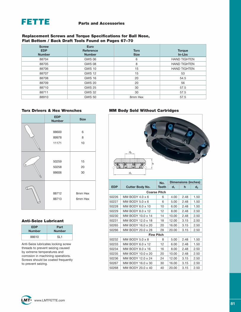
81www.LMTFETTE.com
Parts and Accessories
EDP PartNumber Number
88610 SL1
Anti-Seize Lubricant
Anti-Seize lubricates locking screwthreads to prevent seizing caused by extreme temperatures and corrosion in machining operations.Screws should be coated frequentlyto prevent seizing.
Replacement Screws and Torque Specifications for Ball Nose, Flat Bottom / Back Draft Tools Found on Pages 67–70
EDPNumber Size
88600 6
89978 8
11171 10
50259 15
50258 20
88606 30
88712 8mm Hex
88713 6mm Hex
Screw EuroEDP Reference Torx Torque
Number Number Size In-Lbs
88704 GWS 06 6 HAND TIGHTEN
88705 GWS 08 8 HAND TIGHTEN
88706 GWS 10 15 HAND TIGHTEN
88707 GWS 12 15 53
88708 GWS 16 20 54.5
88709 GWS 20 20 56
88710 GWS 25 30 57.5
88711 GWS 32 30 57.5
88910 GWS 50 8mm Hex 57.5
Torx Drivers & Hex Wrenches
No. Dimensions (inches)
EDP Cutter Body No. Teeth d1 h d2
Coarse Pitch
50226 MM BODY 4.0 x 6 6 4.00 2.48 1.50
50227 MM BODY 5.0 x 6 6 5.00 2.48 1.50
50228 MM BODY 6.0 x 10 10 6.00 2.48 1.50
50229 MM BODY 8.0 x 12 12 8.00 2.48 2.50
50230 MM BODY 10.0 x 14 14 10.00 2.48 2.50
50231 MM BODY 12.0 x 18 18 12.00 3.15 2.50
50265 MM BODY 16.0 x 20 20 16.00 3.15 2.50
50266 MM BODY 20.0 x 28 28 20.00 3.15 2.50
Fine Pitch
50232 MM BODY 5.0 x 8 8 5.00 2.48 1.50
50233 MM BODY 6.0 x 12 12 6.00 2.48 1.50
50234 MM BODY 8.0 x 16 16 8.00 2.48 2.50
50235 MM BODY 10.0 x 20 20 10.00 2.48 2.50
50236 MM BODY 12.0 x 24 24 12.00 3.15 2.50
50267 MM BODY 16.0 x 30 30 16.00 3.15 2.50
50268 MM BODY 20.0 x 40 40 20.00 3.15 2.50
h
d1
d2
MM Body Sold Without Cartridges
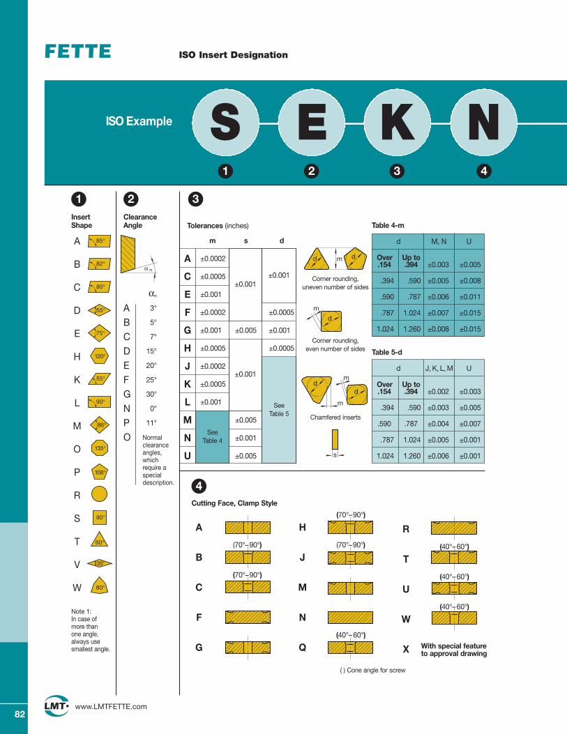
82www.LMTFETTE.com
ISO Insert Designation
Tolerances (inches)
m s d
A ±0.0002
C ±0.0005
E ±0.001
F ±0.0002 ±0.0005
G ±0.001 ±0.005 ±0.001
H ±0.0005 ±0.0005
J ±0.0002
K ±0.0005
L ±0.001
M ±0.005
N ±0.001
U ±0.005
A
(70°–90°)
B
(70°–90°)
C
F
G
(70°–90°)
H
(70°–90°)
J
M
N
(40°– 60°)
Q
R
(40°– 60°)
T
(40°– 60°)
U
(40°– 60°)
W
X With special feature to approval drawing
1InsertShape
A
B
C
D
E
H
K
L
M
O
P
R
S
T
V
W
Note 1: In case of more than one angle, always use smallest angle.
2 3ClearanceAngle
αn
A 3°
B 5°
C 7°
D 15°
E 20°
F 25°
G 30°
N 0°
P 11°
O Normalclearanceangles,whichrequire aspecialdescription.
α n
SeeTable 5
±0.001
Table 4-m
d M, N U
Over Up to .154 .394 ±0.003 ±0.005
.394 .590 ±0.005 ±0.008
.590 .787 ±0.006 ±0.011
.787 1.024 ±0.007 ±0.015
1.024 1.260 ±0.008 ±0.015
Table 5-d
d J, K, L, M U
Over Up to .154 .394 ±0.002 ±0.003
.394 .590 ±0.003 ±0.005
.590 .787 ±0.004 ±0.007
.787 1.024 ±0.005 ±0.001
1.024 1.260 ±0.006 ±0.001
Corner rounding, uneven number of sides
Corner rounding, even number of sides
Chamfered inserts
Cutting Face, Clamp Style
4
d dm
m
d
m
dm
d
s
( ) Cone angle for screw
±0.001
±0.001
1 2 3 4
SeeTable 4
ISO Example S E K N
85°
90°
90°
82°
80°
55°
55°
35°
75°
86°
120°
135°
108°
60°
80°
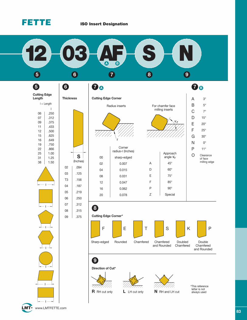
83www.LMTFETTE.com
ISO Insert Designation
12 03 AF S N5
Cutting EdgeLength
6 7
Thickness
S(Inches)
02 .094
03 .125
T3 .156
04 .187
05 .219
06 .250
07 .312
08 .315
09 .375
Radius inserts
Cornerradius-r (Inches)
00 sharp-edged
02 0.007
04 0.015
08 0.031
12 0.047
16 0.062
20 0.078
For chamfer facemilling inserts
Approach angle κr
A 45°
D 60°
E 75°
F 85°
P 90°
Z Special
Cutting Edge Corner
8Cutting Edge Corner*
r
κr
9Direction of Cut*
F E T S K P
Sharp-edged Rounded Chamfered Chamferedand Rounded
DoubledChamfered
DoubleChamfered
and Rounded
R RH cut only L LH cut only N RH and LH cut
*This referenceletter is notalways used
l = Length
5 6 7 8 9
A 3°
B 5°
C 7°
D 15°
E 20°
F 25°
G 30°
N 0°
P 11°
O Clearance of face milling edge
A 7 B
BA
L
L
L
l
l
l
l
l
l
l
l06 .25007 .31209 .37511 .43312 .50015 .62516 .64919 .75022 .86625 1.0031 1.2538 1.50
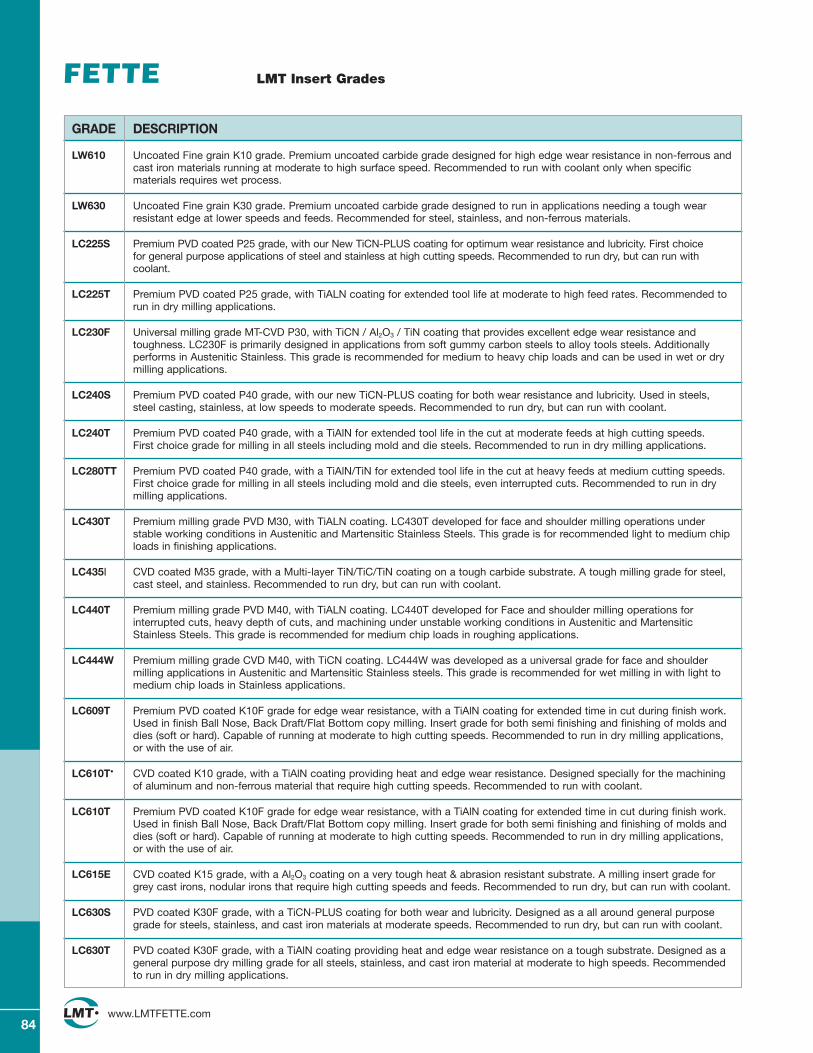
84www.LMTFETTE.com
LMT Insert Grades
GRADE DESCRIPTION
LW610 Uncoated Fine grain K10 grade. Premium uncoated carbide grade designed for high edge wear resistance in non-ferrous andcast iron materials running at moderate to high surface speed. Recommended to run with coolant only when specificmaterials requires wet process.
LW630 Uncoated Fine grain K30 grade. Premium uncoated carbide grade designed to run in applications needing a tough wearresistant edge at lower speeds and feeds. Recommended for steel, stainless, and non-ferrous materials.
LC225S Premium PVD coated P25 grade, with our New TiCN-PLUS coating for optimum wear resistance and lubricity. First choice for general purpose applications of steel and stainless at high cutting speeds. Recommended to run dry, but can run withcoolant.
LC225T Premium PVD coated P25 grade, with TiALN coating for extended tool life at moderate to high feed rates. Recommended torun in dry milling applications.
LC230F Universal milling grade MT-CVD P30, with TiCN / Al2O3 / TiN coating that provides excellent edge wear resistance andtoughness. LC230F is primarily designed in applications from soft gummy carbon steels to alloy tools steels. Additionallyperforms in Austenitic Stainless. This grade is recommended for medium to heavy chip loads and can be used in wet or drymilling applications.
LC240S Premium PVD coated P40 grade, with our new TiCN-PLUS coating for both wear resistance and lubricity. Used in steels,steel casting, stainless, at low speeds to moderate speeds. Recommended to run dry, but can run with coolant.
LC240T Premium PVD coated P40 grade, with a TiAlN for extended tool life in the cut at moderate feeds at high cutting speeds.First choice grade for milling in all steels including mold and die steels. Recommended to run in dry milling applications.
LC280TT Premium PVD coated P40 grade, with a TiAlN/TiN for extended tool life in the cut at heavy feeds at medium cutting speeds.First choice grade for milling in all steels including mold and die steels, even interrupted cuts. Recommended to run in drymilling applications.
LC430T Premium milling grade PVD M30, with TiALN coating. LC430T developed for face and shoulder milling operations understable working conditions in Austenitic and Martensitic Stainless Steels. This grade is for recommended light to medium chiploads in finishing applications.
LC435I CVD coated M35 grade, with a Multi-layer TiN/TiC/TiN coating on a tough carbide substrate. A tough milling grade for steel,cast steel, and stainless. Recommended to run dry, but can run with coolant.
LC440T Premium milling grade PVD M40, with TiALN coating. LC440T developed for Face and shoulder milling operations forinterrupted cuts, heavy depth of cuts, and machining under unstable working conditions in Austenitic and MartensiticStainless Steels. This grade is recommended for medium chip loads in roughing applications.
LC444W Premium milling grade CVD M40, with TiCN coating. LC444W was developed as a universal grade for face and shouldermilling applications in Austenitic and Martensitic Stainless steels. This grade is recommended for wet milling in with light tomedium chip loads in Stainless applications.
LC609T Premium PVD coated K10F grade for edge wear resistance, with a TiAlN coating for extended time in cut during finish work.Used in finish Ball Nose, Back Draft/Flat Bottom copy milling. Insert grade for both semi finishing and finishing of molds anddies (soft or hard). Capable of running at moderate to high cutting speeds. Recommended to run in dry milling applications,or with the use of air.
LC610T• CVD coated K10 grade, with a TiAlN coating providing heat and edge wear resistance. Designed specially for the machiningof aluminum and non-ferrous material that require high cutting speeds. Recommended to run with coolant.
LC610T Premium PVD coated K10F grade for edge wear resistance, with a TiAlN coating for extended time in cut during finish work.Used in finish Ball Nose, Back Draft/Flat Bottom copy milling. Insert grade for both semi finishing and finishing of molds anddies (soft or hard). Capable of running at moderate to high cutting speeds. Recommended to run in dry milling applications,or with the use of air.
LC615E CVD coated K15 grade, with a Al2O3 coating on a very tough heat & abrasion resistant substrate. A milling insert grade forgrey cast irons, nodular irons that require high cutting speeds and feeds. Recommended to run dry, but can run with coolant.
LC630S PVD coated K30F grade, with a TiCN-PLUS coating for both wear and lubricity. Designed as a all around general purposegrade for steels, stainless, and cast iron materials at moderate speeds. Recommended to run dry, but can run with coolant.
LC630T PVD coated K30F grade, with a TiAlN coating providing heat and edge wear resistance on a tough substrate. Designed as ageneral purpose dry milling grade for all steels, stainless, and cast iron material at moderate to high speeds. Recommendedto run in dry milling applications.
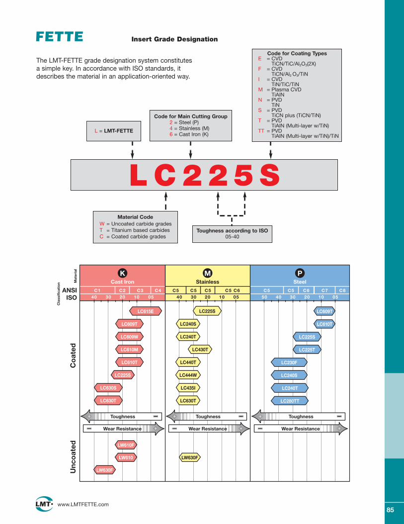
85www.LMTFETTE.com
Insert Grade Designation
LW610F
LW610
LW630F
LC225S
LC444W
LC440T
LC240S
LC240T
LC430T
LC435I
LC630T
LW630F
LC609T
LC610T
LC225S
LC225T
LC240S
LC230F
LC240T
LC280TT
LC615E
LC609T
LC609W
LC610M
LC610T
LC630S
LC225S
LC630T
C140 30 20 10 05 40 30 20 10 05 50 40 30 20 10 05
C2 C3 C4 C5 C5 C5 C5 C6C5 C8ANSIISO
Cla
ssifi
cati
on M
ater
ial
C7C5 C6
SteelStainless
Co
ated
Unc
oat
ed
Cast IronK PM
Toughness
Wear Resistance
Toughness
Wear Resistance
Toughness
Wear Resistance
L C 2 2 5 S
L = LMT-FETTE
The LMT-FETTE grade designation system constitutesa simple key. In accordance with ISO standards, itdescribes the material in an application-oriented way.
Material CodeW = Uncoated carbide gradesT = Titanium based carbidesC = Coated carbide grades
Code for Main Cutting Group2 = Steel (P)4 = Stainless (M)6 = Cast Iron (K)
Toughness according to ISO05-40
Code for Coating TypesE = CVD
TiCN/TiC/Al2O3(2X)F = CVD
TiCN/Al2 O3/TiNI = CVD
TiN/TiC/TiNM = Plasma CVD
TiAINN = PVD
TiNS = PVD
TiCN plus (TiCN/TiN)T = PVD
TiAIN (Multi-layer w/TiN)TT = PVD
TiAIN (Multi-layer w/TiN)/TiN
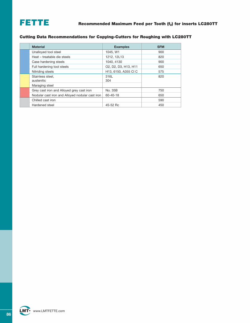
86www.LMTFETTE.com
Unalloyed tool steel 1045, W1 900
Heat – treatable die steels 1212, 12L13 820
Case hardening steels 1040, 4130 900
Full hardening tool steels O2, D2, D3, H13, H11 650
Nitriding steels H13, 6150, A355 Cl C 575
Stainless steel, 316L 820austenitic 304
Maraging steel
Grey cast iron and Alloyed grey cast iron No. 35B 750
Nodular cast iron and Alloyed nodular cast iron 60-40-18 650
Chilled cast iron 590
Hardened steel 45-52 Rc 450
Recommended Maximum Feed per Tooth (fZ) for inserts LC280TT
Cutting Data Recommendations for Copying-Cutters for Roughing with LC280TT
Material Examples SFM
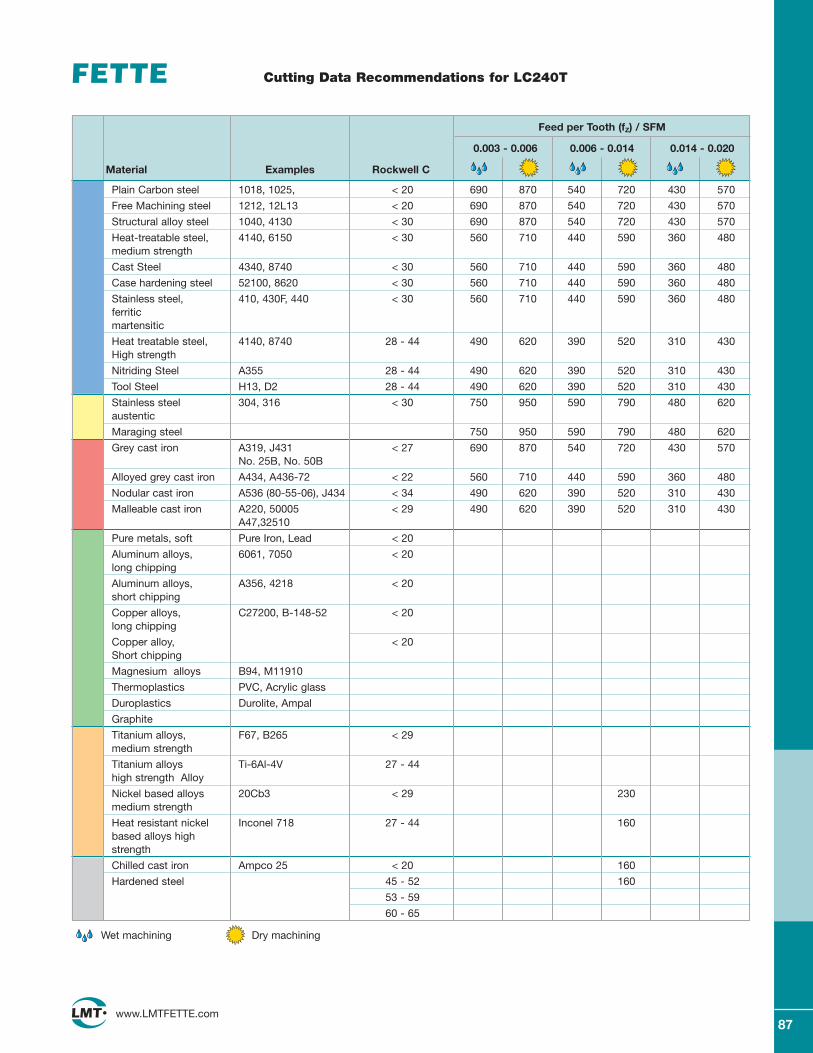
87www.LMTFETTE.com
Cutting Data Recommendations for LC240T
Plain Carbon steel 1018, 1025, < 20 690 870 540 720 430 570
Free Machining steel 1212, 12L13 < 20 690 870 540 720 430 570
Structural alloy steel 1040, 4130 < 30 690 870 540 720 430 570
Heat-treatable steel, 4140, 6150 < 30 560 710 440 590 360 480medium strength
Cast Steel 4340, 8740 < 30 560 710 440 590 360 480
Case hardening steel 52100, 8620 < 30 560 710 440 590 360 480
Stainless steel, 410, 430F, 440 < 30 560 710 440 590 360 480ferriticmartensitic
Heat treatable steel, 4140, 8740 28 - 44 490 620 390 520 310 430High strength
Nitriding Steel A355 28 - 44 490 620 390 520 310 430
Tool Steel H13, D2 28 - 44 490 620 390 520 310 430
Stainless steel 304, 316 < 30 750 950 590 790 480 620austentic
Maraging steel 750 950 590 790 480 620
Grey cast iron A319, J431 < 27 690 870 540 720 430 570No. 25B, No. 50B
Alloyed grey cast iron A434, A436-72 < 22 560 710 440 590 360 480
Nodular cast iron A536 (80-55-06), J434 < 34 490 620 390 520 310 430
Malleable cast iron A220, 50005 < 29 490 620 390 520 310 430A47,32510
Pure metals, soft Pure Iron, Lead < 20
Aluminum alloys, 6061, 7050 < 20long chipping
Aluminum alloys, A356, 4218 < 20short chipping
Copper alloys, C27200, B-148-52 < 20long chipping
Copper alloy, < 20Short chipping
Magnesium alloys B94, M11910
Thermoplastics PVC, Acrylic glass
Duroplastics Durolite, Ampal
Graphite
Titanium alloys, F67, B265 < 29medium strength
Titanium alloys Ti-6Al-4V 27 - 44high strength Alloy
Nickel based alloys 20Cb3 < 29 230medium strength
Heat resistant nickel Inconel 718 27 - 44 160based alloys high strength
Chilled cast iron Ampco 25 < 20 160
Hardened steel 45 - 52 160
53 - 59
60 - 65
Feed per Tooth (fZ) / SFM
0.003 - 0.006 0.006 - 0.014 0.014 - 0.020
Material Examples Rockwell C
Wet machining Dry machining
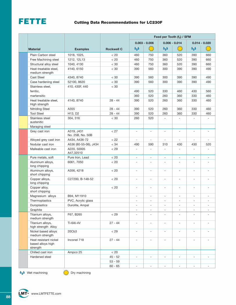
Plain Carbon steel 1018, 1025, < 20 460 750 360 520 390 660
Free Machining steel 1212, 12L13 < 20 460 750 360 520 390 660
Structural alloy steel 1040, 4130 < 30 460 750 360 520 390 660
Heat-treatable steel, 4140, 6150 < 30 390 560 300 390 390 490medium strength
Cast Steel 4340, 8740 < 30 390 560 300 390 390 490
Case hardening steel 52100, 8620 < 30 390 560 300 390 390 490
Stainless steel, 410, 430F, 440 < 30
ferritic, 490 520 330 460 430 560
martensitic 360 520 260 360 330 460
Heat treatable steel, 4140, 8740 28 - 44 390 520 260 360 330 460High strength
Nitriding Steel A355 28 - 44 390 520 260 360 330 460
Tool Steel H13, D2 28 - 44 390 520 260 360 330 460
Stainless steel 304, 316 < 30 260 520 - - - -austenitic
Maraging steel
Grey cast iron A319, J431 < 27 - - - - - -No. 25B, No. 50B
Alloyed grey cast iron A434, A436-72 < 22 - - - - - -
Nodular cast iron A536 (80-55-06), J434 < 34 490 590 310 430 430 520
Malleable cast iron A220, 50005 < 29 - - - - - -A47,32510
Pure metals, soft Pure Iron, Lead < 20 - - - - - -
Aluminum alloys, 6061, 7050 < 20 - - - - - -long chipping
Aluminum alloys, A356, 4218 < 20 - - - - - -short chipping
Copper alloys, C27200, B-148-52 < 20 - - - - - -long chipping
Copper alloy, < 20 - - - - - -short chipping
Magnesium alloys B94, M11910 - - - - - -
Thermoplastics PVC, Acrylic glass - - - - - -
Duroplastics Durolite, Ampal - - - - - -
Graphite - - - - - -
Titanium alloys, F67, B265 < 29 - - - - - -medium strength
Titanium alloys, Ti-6Al-4V 27 - 44 - - - - - -high strength Alloy
Nickel based alloys 20Cb3 < 29 - - - - - -medium strength
Heat resistant nickel Inconel 718 27 - 44 - - - - - -based alloys high strength
Chilled cast iron Ampco 25 < 20
Hardened steel 45 - 52 - - - - - -
53 - 59
60 - 65 - - - - - -
88www.LMTFETTE.com
Cutting Data Recommendations for LC230F
Feed per Tooth (fZ) / SFM
0.003 - 0.006 0.006 - 0.014 0.014 - 0.020
Material Examples Rockwell C
Wet machining Dry machining
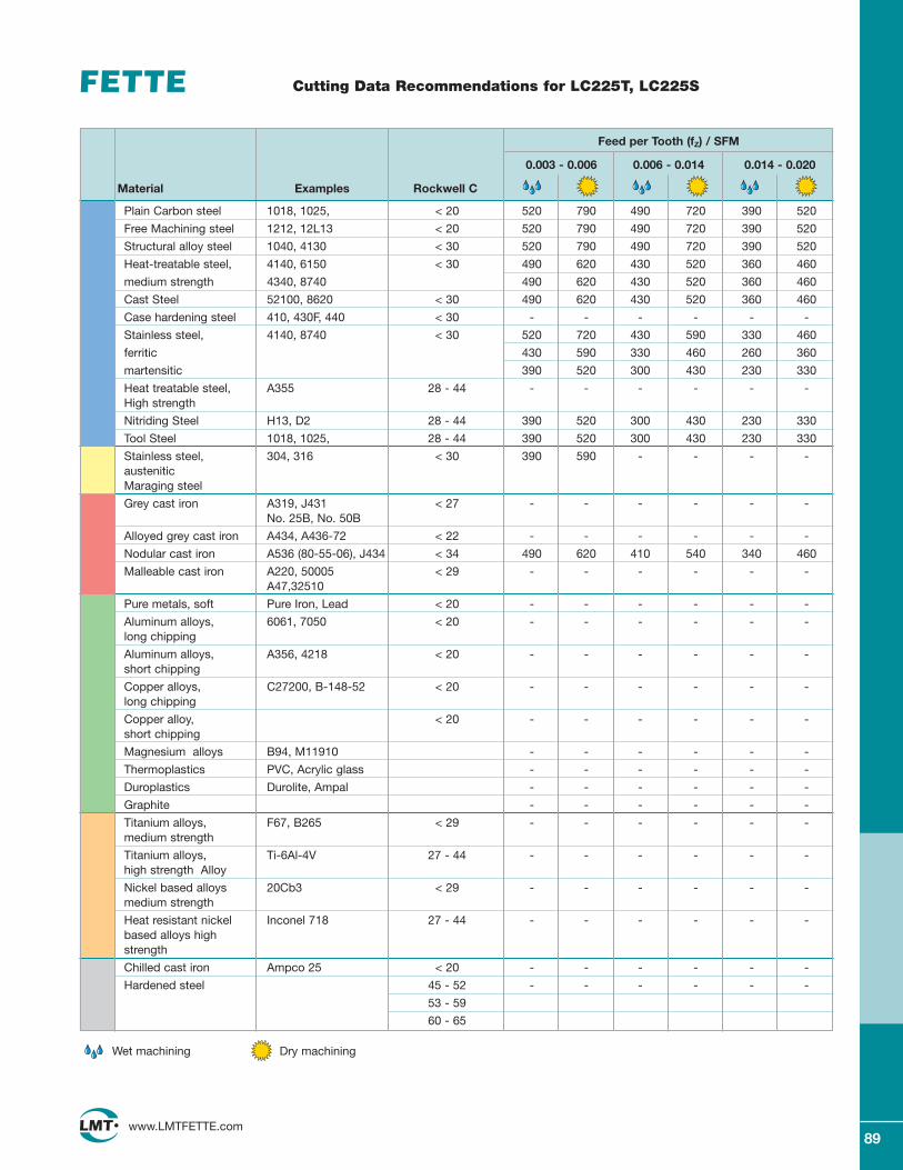
Plain Carbon steel 1018, 1025, < 20 520 790 490 720 390 520
Free Machining steel 1212, 12L13 < 20 520 790 490 720 390 520
Structural alloy steel 1040, 4130 < 30 520 790 490 720 390 520
Heat-treatable steel, 4140, 6150 < 30 490 620 430 520 360 460
medium strength 4340, 8740 490 620 430 520 360 460
Cast Steel 52100, 8620 < 30 490 620 430 520 360 460
Case hardening steel 410, 430F, 440 < 30 - - - - - -
Stainless steel, 4140, 8740 < 30 520 720 430 590 330 460
ferritic 430 590 330 460 260 360
martensitic 390 520 300 430 230 330
Heat treatable steel, A355 28 - 44 - - - - - -High strength
Nitriding Steel H13, D2 28 - 44 390 520 300 430 230 330
Tool Steel 1018, 1025, 28 - 44 390 520 300 430 230 330
Stainless steel, 304, 316 < 30 390 590 - - - -austeniticMaraging steel
Grey cast iron A319, J431 < 27 - - - - - -No. 25B, No. 50B
Alloyed grey cast iron A434, A436-72 < 22 - - - - - -
Nodular cast iron A536 (80-55-06), J434 < 34 490 620 410 540 340 460
Malleable cast iron A220, 50005 < 29 - - - - - -A47,32510
Pure metals, soft Pure Iron, Lead < 20 - - - - - -
Aluminum alloys, 6061, 7050 < 20 - - - - - -long chipping
Aluminum alloys, A356, 4218 < 20 - - - - - -short chipping
Copper alloys, C27200, B-148-52 < 20 - - - - - -long chipping
Copper alloy, < 20 - - - - - -short chipping
Magnesium alloys B94, M11910 - - - - - -
Thermoplastics PVC, Acrylic glass - - - - - -
Duroplastics Durolite, Ampal - - - - - -
Graphite - - - - - -
Titanium alloys, F67, B265 < 29 - - - - - -medium strength
Titanium alloys, Ti-6Al-4V 27 - 44 - - - - - -high strength Alloy
Nickel based alloys 20Cb3 < 29 - - - - - -medium strength
Heat resistant nickel Inconel 718 27 - 44 - - - - - -based alloys high strength
Chilled cast iron Ampco 25 < 20 - - - - - -
Hardened steel 45 - 52 - - - - - -
53 - 59
60 - 65
89www.LMTFETTE.com
Cutting Data Recommendations for LC225T, LC225S
Feed per Tooth (fZ) / SFM
0.003 - 0.006 0.006 - 0.014 0.014 - 0.020
Material Examples Rockwell C
Wet machining Dry machining
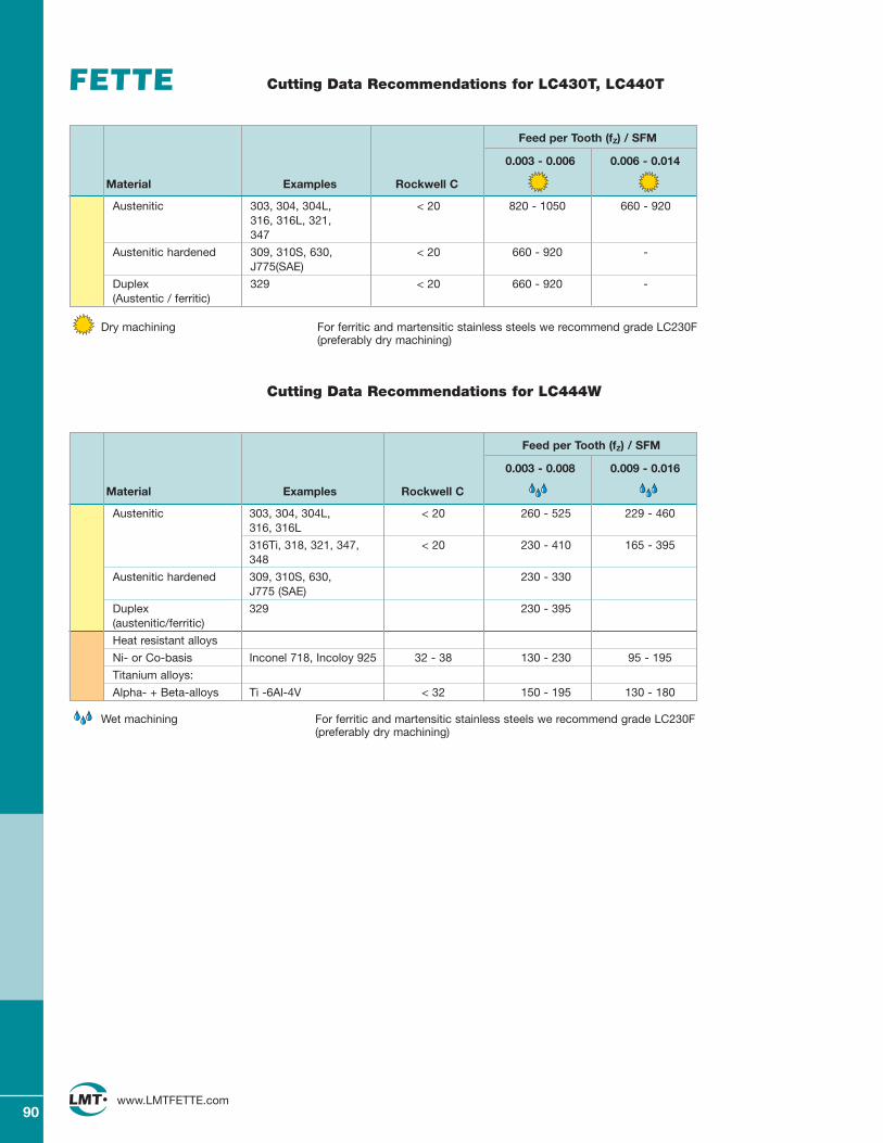
Austenitic 303, 304, 304L, < 20 260 - 525 229 - 460316, 316L
316Ti, 318, 321, 347, < 20 230 - 410 165 - 395348
Austenitic hardened 309, 310S, 630, 230 - 330J775 (SAE)
Duplex 329 230 - 395(austenitic/ferritic)
Heat resistant alloys
Ni- or Co-basis Inconel 718, Incoloy 925 32 - 38 130 - 230 95 - 195
Titanium alloys:
Alpha- + Beta-alloys Ti -6Al-4V < 32 150 - 195 130 - 180
Austenitic 303, 304, 304L, < 20 820 - 1050 660 - 920316, 316L, 321, 347
Austenitic hardened 309, 310S, 630, < 20 660 - 920 -J775(SAE)
Duplex 329 < 20 660 - 920 -(Austentic / ferritic)
90www.LMTFETTE.com
Cutting Data Recommendations for LC430T, LC440T
Dry machining For ferritic and martensitic stainless steels we recommend grade LC230F(preferably dry machining)
Feed per Tooth (fZ) / SFM
0.003 - 0.006 0.006 - 0.014
Material Examples Rockwell C
Cutting Data Recommendations for LC444W
Wet machining For ferritic and martensitic stainless steels we recommend grade LC230F(preferably dry machining)
Feed per Tooth (fZ) / SFM
0.003 - 0.008 0.009 - 0.016
Material Examples Rockwell C
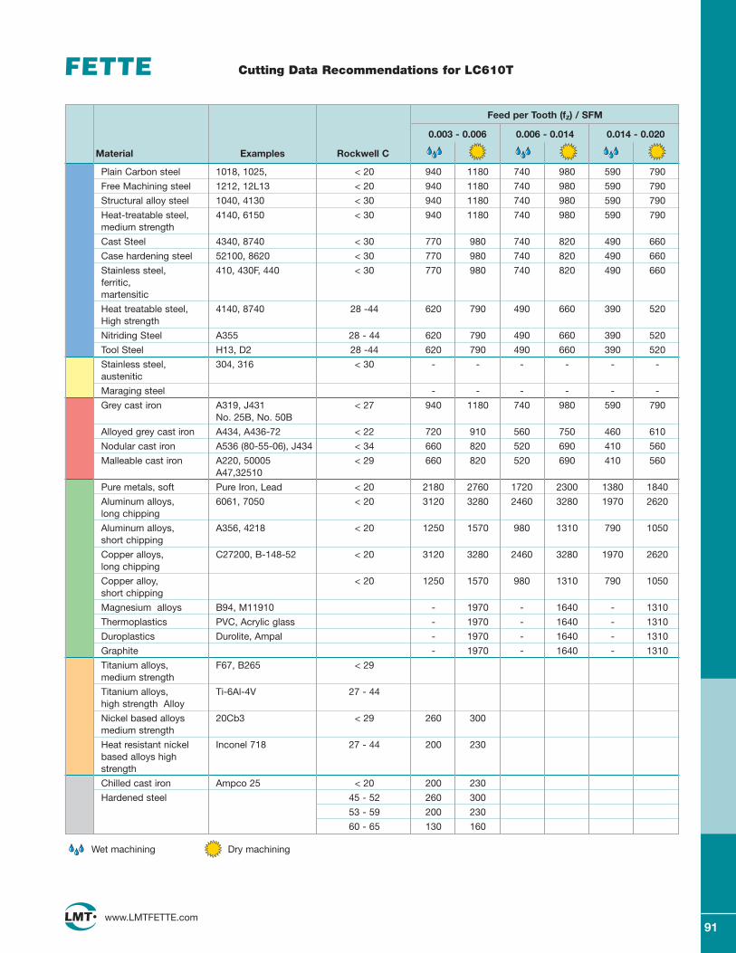
Plain Carbon steel 1018, 1025, < 20 940 1180 740 980 590 790
Free Machining steel 1212, 12L13 < 20 940 1180 740 980 590 790
Structural alloy steel 1040, 4130 < 30 940 1180 740 980 590 790
Heat-treatable steel, 4140, 6150 < 30 940 1180 740 980 590 790medium strength
Cast Steel 4340, 8740 < 30 770 980 740 820 490 660
Case hardening steel 52100, 8620 < 30 770 980 740 820 490 660
Stainless steel, 410, 430F, 440 < 30 770 980 740 820 490 660ferritic,martensitic
Heat treatable steel, 4140, 8740 28 -44 620 790 490 660 390 520High strength
Nitriding Steel A355 28 - 44 620 790 490 660 390 520
Tool Steel H13, D2 28 -44 620 790 490 660 390 520
Stainless steel, 304, 316 < 30 - - - - - -austenitic
Maraging steel - - - - - -
Grey cast iron A319, J431 < 27 940 1180 740 980 590 790No. 25B, No. 50B
Alloyed grey cast iron A434, A436-72 < 22 720 910 560 750 460 610
Nodular cast iron A536 (80-55-06), J434 < 34 660 820 520 690 410 560
Malleable cast iron A220, 50005 < 29 660 820 520 690 410 560A47,32510
Pure metals, soft Pure Iron, Lead < 20 2180 2760 1720 2300 1380 1840
Aluminum alloys, 6061, 7050 < 20 3120 3280 2460 3280 1970 2620long chipping
Aluminum alloys, A356, 4218 < 20 1250 1570 980 1310 790 1050short chipping
Copper alloys, C27200, B-148-52 < 20 3120 3280 2460 3280 1970 2620long chipping
Copper alloy, < 20 1250 1570 980 1310 790 1050short chipping
Magnesium alloys B94, M11910 - 1970 - 1640 - 1310
Thermoplastics PVC, Acrylic glass - 1970 - 1640 - 1310
Duroplastics Durolite, Ampal - 1970 - 1640 - 1310
Graphite - 1970 - 1640 - 1310
Titanium alloys, F67, B265 < 29medium strength
Titanium alloys, Ti-6Al-4V 27 - 44high strength Alloy
Nickel based alloys 20Cb3 < 29 260 300medium strength
Heat resistant nickel Inconel 718 27 - 44 200 230based alloys high strength
Chilled cast iron Ampco 25 < 20 200 230
Hardened steel 45 - 52 260 300
53 - 59 200 230
60 - 65 130 160
91www.LMTFETTE.com
Cutting Data Recommendations for LC610T
Feed per Tooth (fZ) / SFM
0.003 - 0.006 0.006 - 0.014 0.014 - 0.020
Material Examples Rockwell C
Wet machining Dry machining
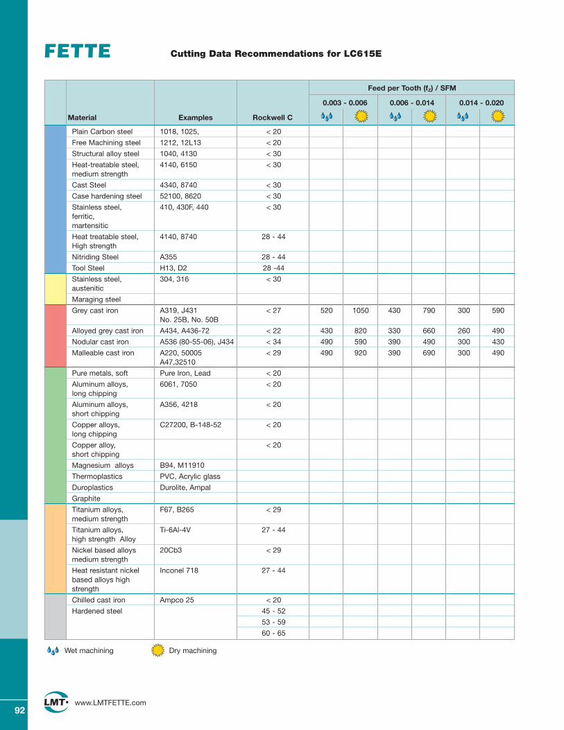
92www.LMTFETTE.com
Cutting Data Recommendations for LC615E
Plain Carbon steel 1018, 1025, < 20
Free Machining steel 1212, 12L13 < 20
Structural alloy steel 1040, 4130 < 30
Heat-treatable steel, 4140, 6150 < 30medium strength
Cast Steel 4340, 8740 < 30
Case hardening steel 52100, 8620 < 30
Stainless steel, 410, 430F, 440 < 30ferritic,martensitic
Heat treatable steel, 4140, 8740 28 - 44High strength
Nitriding Steel A355 28 - 44
Tool Steel H13, D2 28 -44
Stainless steel, 304, 316 < 30austenitic
Maraging steel
Grey cast iron A319, J431 < 27 520 1050 430 790 300 590No. 25B, No. 50B
Alloyed grey cast iron A434, A436-72 < 22 430 820 330 660 260 490
Nodular cast iron A536 (80-55-06), J434 < 34 490 590 390 490 300 430
Malleable cast iron A220, 50005 < 29 490 920 390 690 300 490A47,32510
Pure metals, soft Pure Iron, Lead < 20
Aluminum alloys, 6061, 7050 < 20long chipping
Aluminum alloys, A356, 4218 < 20short chipping
Copper alloys, C27200, B-148-52 < 20long chipping
Copper alloy, < 20short chipping
Magnesium alloys B94, M11910
Thermoplastics PVC, Acrylic glass
Duroplastics Durolite, Ampal
Graphite
Titanium alloys, F67, B265 < 29medium strength
Titanium alloys, Ti-6Al-4V 27 - 44high strength Alloy
Nickel based alloys 20Cb3 < 29medium strength
Heat resistant nickel Inconel 718 27 - 44based alloys high strength
Chilled cast iron Ampco 25 < 20
Hardened steel 45 - 52
53 - 59
60 - 65
Feed per Tooth (fZ) / SFM
0.003 - 0.006 0.006 - 0.014 0.014 - 0.020
Material Examples Rockwell C
Wet machining Dry machining
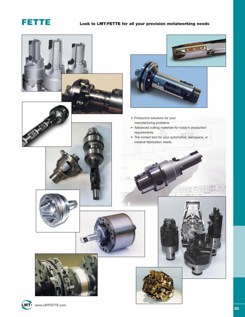
93www.LMTFETTE.com
Look to LMT-FETTE for all your precision metalworking needs
• Productive solutions for your
manufacturing problems
• Advanced cutting materials for today’s production
requirements.
• The correct tool for your automotive, aerospace, or
medical fabrication needs.
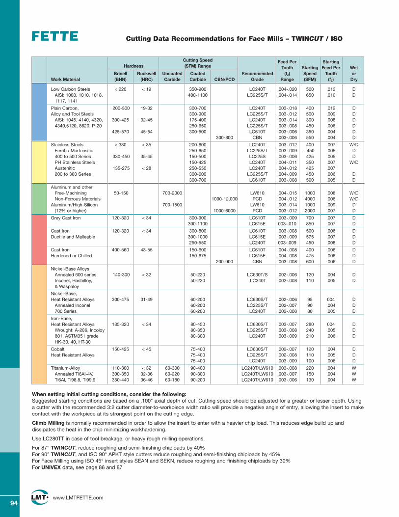
94www.LMTFETTE.com
Cutting Data Recommendations for Face Mills – TWINCUT / ISO
When setting initial cutting conditions, consider the following:Suggested starting conditions are based on a .100" axial depth of cut. Cutting speed should be adjusted for a greater or lesser depth. Usinga cutter with the recommended 3:2 cutter diameter-to-workpiece width ratio will provide a negative angle of entry, allowing the insert to makecontact with the workpiece at its strongest point on the cutting edge.
Climb Milling is normally recommended in order to allow the insert to enter with a heavier chip load. This reduces edge build up anddissipates the heat in the chip minimizing workhardening.
Use LC280TT in case of tool breakage, or heavy rough milling operations.
For 87° TWINCUT, reduce roughing and semi-finishing chiploads by 40% For 90° TWINCUT, and ISO 90° APKT style cutters reduce roughing and semi-finishing chiploads by 45%For Face Milling using ISO 45° insert styles SEAN and SEKN, reduce roughing and finishing chiploads by 30%For UNIVEX data, see page 86 and 87
Cutting Speed Feed Per StartingHardness (SFM) Range Tooth Starting Feed Per Wet
Brinell Rockwell Uncoated Coated Recommended (fZ) Speed Tooth orWork Material (BHN) (HRC) Carbide Carbide CBN/PCD Grade Range (SFM) (fZ) Dry
Low Carbon Steels < 220 < 19 350-900 LC240T .004-.020 500 .012 DAISI: 1008, 1010, 1018, 400-1100 LC225S/T .004-.014 650 .010 D1117, 1141
Plain Carbon, 200-300 19-32 300-700 LC240T .003-.018 400 .012 DAlloy and Tool Steels 300-900 LC225S/T .003-.012 500 .009 D
AISI: 1045, 4140, 4320, 300-425 32-45 175-400 LC240T .003-.014 300 .008 D4340,5120, 8620, P-20 250-650 LC225S/T .003-.008 450 .006 D
425-570 45-54 300-500 LC610T .003-.006 350 .004 D300-800 CBN .003-.006 550 .004 D
Stainless Steels < 330 < 35 200-600 LC240T .003-.012 400 .007 W/DFerritic-Martensitic 250-650 LC225S/T .003-.009 .450 .005 D400 to 500 Series 330-450 35-45 150-500 LC225S .003-.006 425 .005 DPH Stainless Steels 150-425 LC240T .004-.011 350 .007 W/DAustenitic 135-275 < 28 250-550 LC240T .004-.012 425 .007200 to 300 Series 300-600 LC225S/T .004-.009 450 .006 D
300-700 LC610T .003-.008 500 .005 D
Aluminum and otherFree-Machining 50-150 700-2000 LW610 .004-.015 1000 .008 W/DNon-Ferrous Materials 1000-12,000 PCD .004-.012 4000 .006 W/D
Aluminum/High-Silicon 700-1500 LW610 .003-.014 1000 .009 D(12% or higher) 1000-6000 PCD .003-.012 2000 .007 D
Grey Cast Iron 120-320 < 34 300-900 LC610T .003-.009 700 .007 D300-1100 LC615E 003-.010 850 .007 D
Cast Iron 120-320 < 34 300-800 LC610T .003-.008 500 .006 DDuctile and Malleable 300-1000 LC615E .003-.009 575 .007 D
250-550 LC240T 003-.009 450 .008 D
Cast Iron 400-560 43-55 150-600 LC610T .004-.008 400 .006 DHardened or Chilled 150-675 LC615E .004-.008 475 .006 D
200-900 CBN .003-.008 600 .006 D
Nickel-Base Alloys Annealed 600 series 140-300 < 32 50-220 LC630T/S .002-.006 120 .004 DInconel, Hastelloy, 50-220 LC240T .002-.008 110 .005 D& Waspaloy
Nickel-Base, Heat Resistant Alloys 300-475 31-49 60-200 LC630S/T .002-.006 95 004 D
Annealed Inconel 60-200 LC225S/T .002-.007 90 .004 D700 Series 60-200 LC240T .002-.008 80 .005 D
Iron-Base, Heat Resistant Alloys 135-320 < 34 80-450 LC630S/T .003-.007 280 004 D
Wrought: A-286, Incoloy 80-350 LC225S/T .003-.008 240 .005 D801, ASTM351 grade 80-300 LC240T .003-.009 210 .006 DHK-30, 40, HT-30
Cobalt 150-425 < 45 75-400 LC630S/T .002-.007 120 .004 DHeat Resistant Alloys 75-400 LC225S/T .002-.008 110 .005 D
75-400 LC240T .003-.009 100 .006 D
Titanium-Alloy 110-300 < 32 60-300 90-400 LC240T/LW610 .003-.008 220 .004 WAnnealed Ti6Al-4V, 300-350 32-36 60-220 90-300 LC240T/LW610 .003-.007 150 .004 WTi6Al, Ti98.8, Ti99.9 350-440 36-46 60-180 90-200 LC240T/LW610 .003-.006 130 .004 W
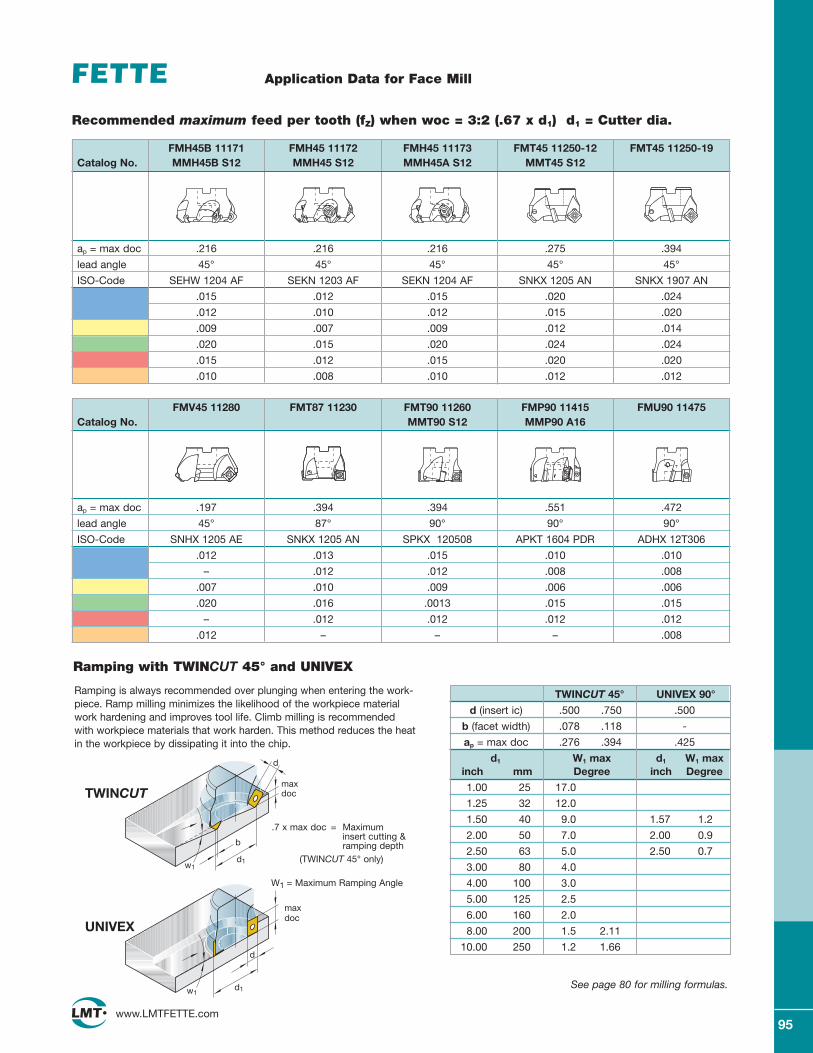
95www.LMTFETTE.com
Application Data for Face Mill
.7 x max doc = Maximum insert cutting & ramping depth
(TWINCUT 45° only)
Ramping is always recommended over plunging when entering the work-piece. Ramp milling minimizes the likelihood of the workpiece materialwork hardening and improves tool life. Climb milling is recommendedwith workpiece materials that work harden. This method reduces the heatin the workpiece by dissipating it into the chip.
See page 80 for milling formulas.
d
maxdoc
maxdoc
d1
w1
w1
b
d
d1
TWINCUT
UNIVEX
TWINCUT 45° UNIVEX 90°
d (insert ic) .500 .750 .500
b (facet width) .078 .118 -
ap = max doc .276 .394 .425
d1 W1 max d1 W1 maxinch mm Degree inch Degree
1.00 25 17.0
1.25 32 12.0
1.50 40 9.0 1.57 1.2
2.00 50 7.0 2.00 0.9
2.50 63 5.0 2.50 0.7
3.00 80 4.0
4.00 100 3.0
5.00 125 2.5
6.00 160 2.0
8.00 200 1.5 2.11
10.00 250 1.2 1.66
W1 = Maximum Ramping Angle
Ramping with TWINCUT 45° and UNIVEX
ap = max doc .216 .216 .216 .275 .394
lead angle 45° 45° 45° 45° 45°
ISO-Code SEHW 1204 AF SEKN 1203 AF SEKN 1204 AF SNKX 1205 AN SNKX 1907 AN
.015 .012 .015 .020 .024
.012 .010 .012 .015 .020
.009 .007 .009 .012 .014
.020 .015 .020 .024 .024
.015 .012 .015 .020 .020
.010 .008 .010 .012 .012
FMH45B 11171 FMH45 11172 FMH45 11173 FMT45 11250-12 FMT45 11250-19 Catalog No. MMH45B S12 MMH45 S12 MMH45A S12 MMT45 S12
Recommended maximum feed per tooth (fZ) when woc = 3:2 (.67 x d1) d1 = Cutter dia.
ap = max doc .197 .394 .394 .551 .472
lead angle 45° 87° 90° 90° 90°
ISO-Code SNHX 1205 AE SNKX 1205 AN SPKX 120508 APKT 1604 PDR ADHX 12T306
.012 .013 .015 .010 .010
– .012 .012 .008 .008
.007 .010 .009 .006 .006
.020 .016 .0013 .015 .015
– .012 .012 .012 .012
.012 – – – .008
FMV45 11280 FMT87 11230 FMT90 11260 FMP90 11415 FMU90 11475 Catalog No. MMT90 S12 MMP90 A16
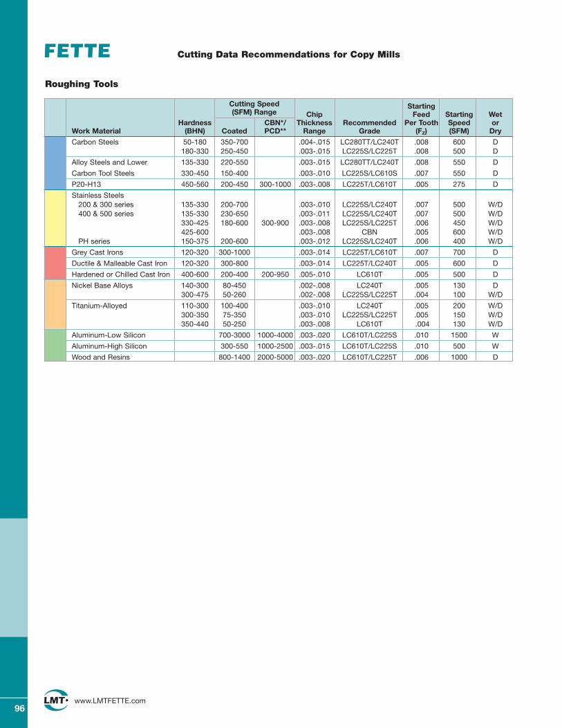
96www.LMTFETTE.com
Cutting Data Recommendations for Copy Mills
Roughing Tools
Cutting Speed Starting (SFM) Range Chip Feed Starting Wet
Hardness CBN*/ Thickness Recommended Per Tooth Speed orWork Material (BHN) Coated PCD** Range Grade (FZ) (SFM) Dry
Carbon Steels 50-180 350-700 .004-.015 LC280TT/LC240T .008 600 D180-330 250-450 .003-.015 LC225S/LC225T .008 500 D
Alloy Steels and Lower 135-330 220-550 .003-.015 LC280TT/LC240T .008 550 D
Carbon Tool Steels 330-450 150-400 .003-.010 LC225S/LC610S .007 550 D
P20-H13 450-560 200-450 300-1000 .003-.008 LC225T/LC610T .005 275 D
Stainless Steels200 & 300 series 135-330 200-700 .003-.010 LC225S/LC240T .007 500 W/D400 & 500 series 135-330 230-650 .003-.011 LC225S/LC240T .007 500 W/D
330-425 180-600 300-900 .003-.008 LC225S/LC225T .006 450 W/D425-600 .003-.008 CBN .005 600 W/D
PH series 150-375 200-600 .003-.012 LC225S/LC240T .006 400 W/D
Grey Cast Irons 120-320 300-1000 .003-.014 LC225T/LC610T .007 700 D
Ductile & Malleable Cast Iron 120-320 300-800 .003-.014 LC225T/LC240T .005 600 D
Hardened or Chilled Cast Iron 400-600 200-400 200-950 .005-.010 LC610T .005 500 D
Nickel Base Alloys 140-300 80-450 .002-.008 LC240T .005 130 D300-475 50-260 .002-.008 LC225S/LC225T .004 100 W/D
Titanium-Alloyed 110-300 100-400 .003-.010 LC240T .005 200 W/D300-350 75-350 .003-.010 LC225S/LC225T .005 150 W/D350-440 50-250 .003-.008 LC610T .004 130 W/D
Aluminum-Low Silicon 700-3000 1000-4000 .003-.020 LC610T/LC225S .010 1500 W
Aluminum-High Silicon 300-550 1000-2500 .003-.015 LC610T/LC225S .010 500 W
Wood and Resins 800-1400 2000-5000 .003-.020 LC610T/LC225T .006 1000 D
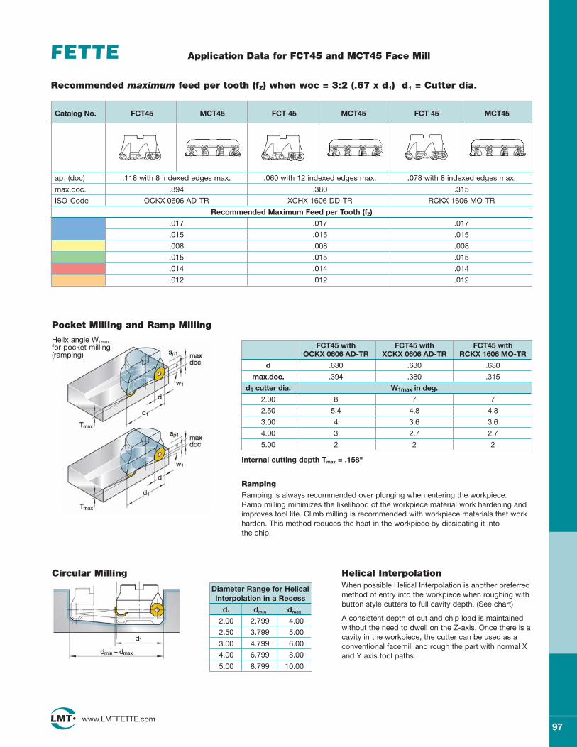
97www.LMTFETTE.com
Application Data for FCT45 and MCT45 Face Mill
Helical InterpolationWhen possible Helical Interpolation is another preferredmethod of entry into the workpiece when roughing withbutton style cutters to full cavity depth. (See chart)
A consistent depth of cut and chip load is maintainedwithout the need to dwell on the Z-axis. Once there is acavity in the workpiece, the cutter can be used as aconventional facemill and rough the part with normal Xand Y axis tool paths.
Pocket Milling and Ramp Milling
Circular Milling
Helix angle W1max.for pocket milling (ramping)
Ramping
Ramping is always recommended over plunging when entering the workpiece. Ramp milling minimizes the likelihood of the workpiece material work hardening andimproves tool life. Climb milling is recommended with workpiece materials that workharden. This method reduces the heat in the workpiece by dissipating it into the chip.
FCT45 with FCT45 with FCT45 with OCKX 0606 AD-TR XCKX 0606 AD-TR RCKX 1606 MO-TR
d .630 .630 .630
max.doc. .394 .380 .315
d1 cutter dia. W1max in deg.
2.00 8 7 7
2.50 5.4 4.8 4.8
3.00 4 3.6 3.6
4.00 3 2.7 2.7
5.00 2 2 2
Internal cutting depth Tmax = .158"
Diameter Range for HelicalInterpolation in a Recess
d1 dmin dmax
2.00 2.799 4.00
2.50 3.799 5.00
3.00 4.799 6.00
4.00 6.799 8.00
5.00 8.799 10.00
ap1 (doc) .118 with 8 indexed edges max. .060 with 12 indexed edges max. .078 with 8 indexed edges max.
max.doc. .394 .380 .315
ISO-Code OCKX 0606 AD-TR XCHX 1606 DD-TR RCKX 1606 MO-TR
Recommended Maximum Feed per Tooth (fZ)
.017 .017 .017
.015 .015 .015
.008 .008 .008
.015 .015 .015
.014 .014 .014
.012 .012 .012
Catalog No. FCT45 MCT45 FCT 45 MCT45 FCT 45 MCT45
Recommended maximum feed per tooth (fZ) when woc = 3:2 (.67 x d1) d1 = Cutter dia.
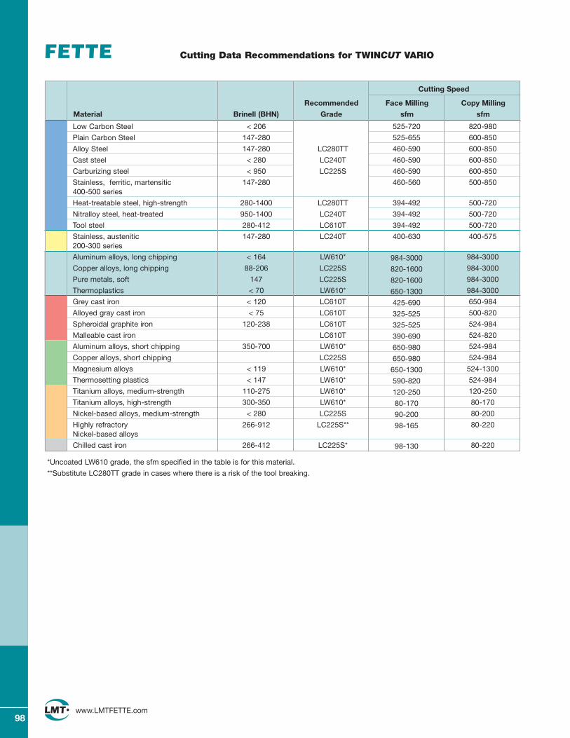
98www.LMTFETTE.com
Cutting Data Recommendations for TWINCUT VARIO
Low Carbon Steel < 206 525-720 820-980
Plain Carbon Steel 147-280 525-655 600-850
Alloy Steel 147-280 LC280TT 460-590 600-850
Cast steel < 280 LC240T 460-590 600-850
Carburizing steel < 950 LC225S 460-590 600-850
Stainless, ferritic, martensitic 147-280 460-560 500-850400-500 series
Heat-treatable steel, high-strength 280-1400 LC280TT 394-492 500-720
Nitralloy steel, heat-treated 950-1400 LC240T 394-492 500-720
Tool steel 280-412 LC610T 394-492 500-720
Stainless, austenitic 147-280 LC240T 400-630 400-575200-300 series
Aluminum alloys, long chipping < 164 LW610* 984-3000 984-3000
Copper alloys, long chipping 88-206 LC225S 820-1600 984-3000
Pure metals, soft 147 LC225S 820-1600 984-3000
Thermoplastics < 70 LW610* 650-1300 984-3000
Grey cast iron < 120 LC610T 425-690 650-984
Alloyed gray cast iron < 75 LC610T 325-525 500-820
Spheroidal graphite iron 120-238 LC610T 325-525 524-984
Malleable cast iron LC610T 390-690 524-820
Aluminum alloys, short chipping 350-700 LW610* 650-980 524-984
Copper alloys, short chipping LC225S 650-980 524-984
Magnesium alloys < 119 LW610* 650-1300 524-1300
Thermosetting plastics < 147 LW610* 590-820 524-984
Titanium alloys, medium-strength 110-275 LW610* 120-250 120-250
Titanium alloys, high-strength 300-350 LW610* 80-170 80-170
Nickel-based alloys, medium-strength < 280 LC225S 90-200 80-200
Highly refractory 266-912 LC225S** 98-165 80-220Nickel-based alloys
Chilled cast iron 266-412 LC225S* 98-130 80-220
Cutting Speed
Recommended Face Milling Copy Milling
Material Brinell (BHN) Grade sfm sfm
*Uncoated LW610 grade, the sfm specified in the table is for this material.
**Substitute LC280TT grade in cases where there is a risk of the tool breaking.

99www.LMTFETTE.com
Application Data for Universal Milling TWINCUT VARIO
max.doc. 0.315 0.394
min.doc. 0.079 0.079
ISO-Code RCKX 1606 MO-TR OCKX 0606 AD-TR
Recommended Maximum Feed per Tooth (fZ)
0.018 0.014
0.016 0.012
0.008 0.006
0.016 0.012
0.014 0.012
0.012 0.010
Catalog No. Round Octagonal
Pocket Milling and Ramp Milling
Circular Milling
Max. W1 angle whenramping with TWINCUT VARIO
Ramping Ramping is always recommended over plunging when entering the workpiece. Ramp milling minimizes the likelihood of the workpiece material work hardening andimproves tool life. Climb milling is recommended with workpiece materials that workharden. This method reduces the hear in the workpiece by dissipating it into the chip.
TWINCUT VARIO with TWINCUT VARIO with RCKX 1606 MO-TR OCKX 0606 AD-TR
d1 inch W1° W1°
1.50 1.3° 1.1°
2.00 1.8° 1.6°
2.50 2.3° 2.1°
3.00 2.8° 2.6°
4.00 3.8° 3.6°
Internal cut depth Tmax = 0.157"
Diameter Range for HelicalInterpolation in One Operation
d1 dmin dmax
1.50 3.06 4.54
2.00 4.06 5.54
2.50 5.06 6.54
3.00 6.06 7.54
4.00 8.06 9.54
Face Milling
a
a
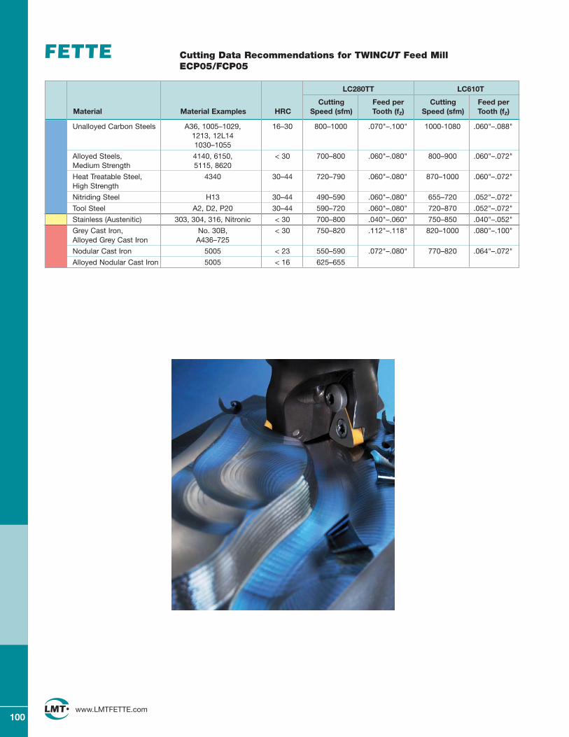
100www.LMTFETTE.com
Cutting Data Recommendations for TWINCUT Feed MillECP05/FCP05
Unalloyed Carbon Steels A36, 1005–1029, 16–30 800–1000 .070"–.100" 1000-1080 .060"–.088"1213, 12L141030–1055
Alloyed Steels, 4140, 6150, < 30 700–800 .060"–.080" 800–900 .060"–.072"Medium Strength 5115, 8620
Heat Treatable Steel, 4340 30–44 720–790 .060"–.080" 870–1000 .060"–.072"High Strength
Nitriding Steel H13 30–44 490–590 .060"–.080" 655–720 .052"–.072"
Tool Steel A2, D2, P20 30–44 590–720 .060"–.080" 720–870 .052"–.072"
Stainless (Austenitic) 303, 304, 316, Nitronic < 30 700–800 .040"–.060" 750–850 .040"–.052"
Grey Cast Iron, No. 30B, < 30 750–820 .112"–.118" 820–1000 .080"–.100"Alloyed Grey Cast Iron A436–725
Nodular Cast Iron 5005 < 23 550–590 .072"–.080" 770–820 .064"–.072"
Alloyed Nodular Cast Iron 5005 < 16 625–655
LC280TT LC610T
Cutting Feed per Cutting Feed perMaterial Material Examples HRC Speed (sfm) Tooth (fZ) Speed (sfm) Tooth (fZ)
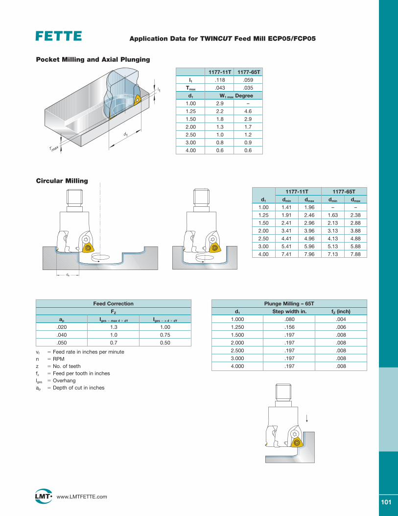
101www.LMTFETTE.com
Application Data for TWINCUT Feed Mill ECP05/FCP05
de
l1
d1
Tmax
Pocket Milling and Axial Plunging
Circular Milling
Feed Correction
FZ
ap Iges � max 4 � d1 Iges � > 4 � d1
.020 1.3 1.00
.040 1.0 0.75
.050 0.7 0.50
vf � Feed rate in inches per minuten � RPMz � No. of teethfz � Feed per tooth in incheslges � Overhangap � Depth of cut in inches
1177-11T 1177-65T
d1 dmin dmax dmin dmax
1.00 1.41 1.96 – –
1.25 1.91 2.46 1.63 2.38
1.50 2.41 2.96 2.13 2.88
2.00 3.41 3.96 3.13 3.88
2.50 4.41 4.96 4.13 4.88
3.00 5.41 5.96 5.13 5.88
4.00 7.41 7.96 7.13 7.88
1177-11T 1177-65T
l1 .118 .059
Tmax .043 .035
d1 W1 max Degree
1.00 2.9 –
1.25 2.2 4.6
1.50 1.8 2.9
2.00 1.3 1.7
2.50 1.0 1.2
3.00 0.8 0.9
4.00 0.6 0.6
Plunge Milling – 65T
d1 Step width in. fZ (inch)
1.000 .080 .004
1.250 .156 .006
1.500 .197 .008
2.000 .197 .008
2.500 .197 .008
3.000 .197 .008
4.000 .197 .008
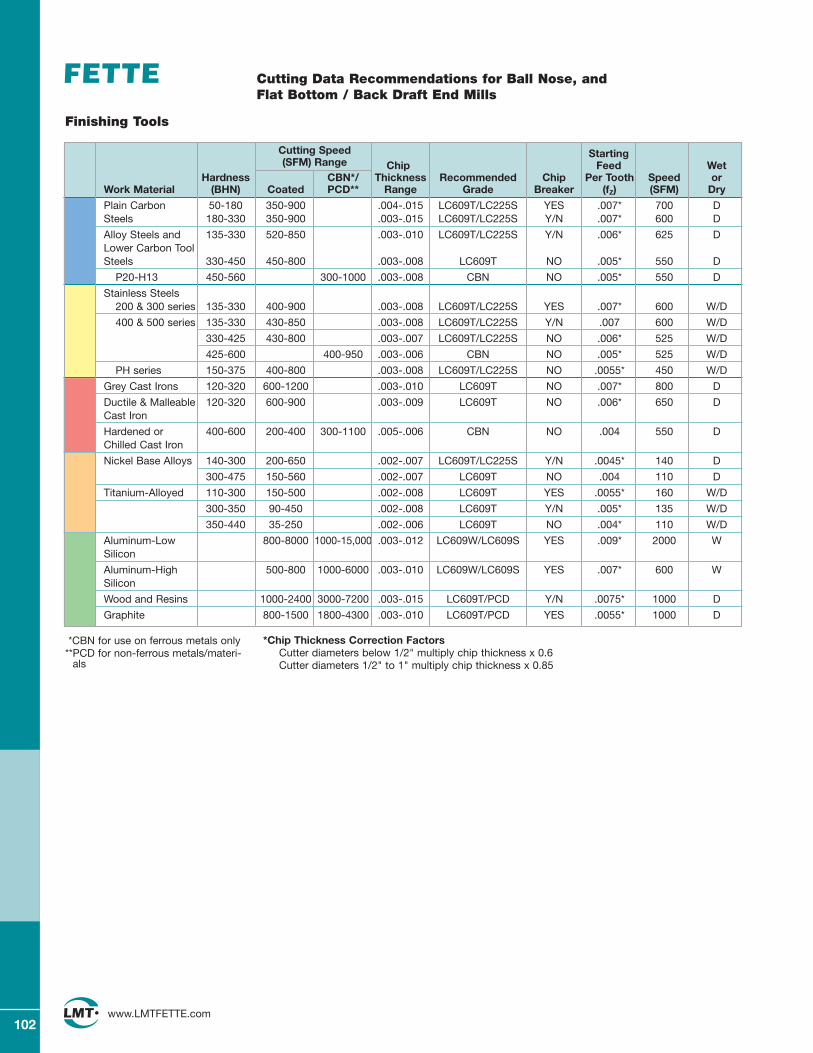
102www.LMTFETTE.com
*Chip Thickness Correction FactorsCutter diameters below 1/2" multiply chip thickness x 0.6Cutter diameters 1/2" to 1" multiply chip thickness x 0.85
*CBN for use on ferrous metals only **PCD for non-ferrous metals/materi-
als
Cutting Data Recommendations for Ball Nose, and Flat Bottom / Back Draft End Mills
Finishing Tools
Cutting Speed Starting (SFM) Range Chip Feed Wet
Hardness CBN*/ Thickness Recommended Chip Per Tooth Speed orWork Material (BHN) Coated PCD** Range Grade Breaker (fZ) (SFM) Dry
Plain Carbon 50-180 350-900 .004-.015 LC609T/LC225S YES .007* 700 DSteels 180-330 350-900 .003-.015 LC609T/LC225S Y/N .007* 600 D
Alloy Steels and 135-330 520-850 .003-.010 LC609T/LC225S Y/N .006* 625 DLower Carbon Tool Steels 330-450 450-800 .003-.008 LC609T NO .005* 550 D
P20-H13 450-560 300-1000 .003-.008 CBN NO .005* 550 D
Stainless Steels 200 & 300 series 135-330 400-900 .003-.008 LC609T/LC225S YES .007* 600 W/D
400 & 500 series 135-330 430-850 .003-.008 LC609T/LC225S Y/N .007 600 W/D
330-425 430-800 .003-.007 LC609T/LC225S NO .006* 525 W/D
425-600 400-950 .003-.006 CBN NO .005* 525 W/D
PH series 150-375 400-800 .003-.008 LC609T/LC225S NO .0055* 450 W/D
Grey Cast Irons 120-320 600-1200 .003-.010 LC609T NO .007* 800 D
Ductile & Malleable 120-320 600-900 .003-.009 LC609T NO .006* 650 DCast Iron
Hardened or 400-600 200-400 300-1100 .005-.006 CBN NO .004 550 DChilled Cast Iron
Nickel Base Alloys 140-300 200-650 .002-.007 LC609T/LC225S Y/N .0045* 140 D
300-475 150-560 .002-.007 LC609T NO .004 110 D
Titanium-Alloyed 110-300 150-500 .002-.008 LC609T YES .0055* 160 W/D
300-350 90-450 .002-.008 LC609T Y/N .005* 135 W/D
350-440 35-250 .002-.006 LC609T NO .004* 110 W/D
Aluminum-Low 800-8000 1000-15,000 .003-.012 LC609W/LC609S YES .009* 2000 WSilicon
Aluminum-High 500-800 1000-6000 .003-.010 LC609W/LC609S YES .007* 600 WSilicon
Wood and Resins 1000-2400 3000-7200 .003-.015 LC609T/PCD Y/N .0075* 1000 D
Graphite 800-1500 1800-4300 .003-.010 LC609T/PCD YES .0055* 1000 D
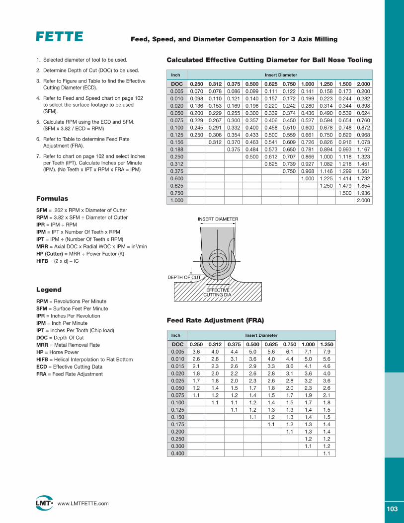
103www.LMTFETTE.com
Feed, Speed, and Diameter Compensation for 3 Axis Milling
1. Selected diameter of tool to be used.
2. Determine Depth of Cut (DOC) to be used.
3. Refer to Figure and Table to find the EffectiveCutting Diameter (ECD).
4. Refer to Feed and Speed chart on page 102 to select the surface footage to be used(SFM).
5. Calculate RPM using the ECD and SFM. (SFM x 3.82 / ECD = RPM)
6. Refer to Table to determine Feed RateAdjustment (FRA).
7. Refer to chart on page 102 and select Inchesper Teeth (IPT). Calculate Inches per Minute(IPM). (No Teeth x IPT x RPM x FRA = IPM)
DOC 0.250 0.312 0.375 0.500 0.625 0.750 1.000 1.250 1.500 2.0000.005 0.070 0.078 0.086 0.099 0.111 0.122 0.141 0.158 0.173 0.2000.010 0.098 0.110 0.121 0.140 0.157 0.172 0.199 0.223 0.244 0.2820.020 0.136 0.153 0.169 0.196 0.220 0.242 0.280 0.314 0.344 0.3980.050 0.200 0.229 0.255 0.300 0.339 0.374 0.436 0.490 0.539 0.6240.075 0.229 0.267 0.300 0.357 0.406 0.450 0.527 0.594 0.654 0.7600.100 0.245 0.291 0.332 0.400 0.458 0.510 0.600 0.678 0.748 0.8720.125 0.250 0.306 0.354 0.433 0.500 0.559 0.661 0.750 0.829 0.9680.156 0.312 0.370 0.463 0.541 0.609 0.726 0.826 0.916 1.0730.188 0.375 0.484 0.573 0.650 0.781 0.894 0.993 1.1670.250 0.500 0.612 0.707 0.866 1.000 1.118 1.3230.312 0.625 0.739 0.927 1.082 1.218 1.4510.375 0.750 0.968 1.146 1.299 1.5610.600 1.000 1.225 1.414 1.7320.625 1.250 1.479 1.8540.750 1.500 1.9361.000 2.000
Calculated Effective Cutting Diameter for Ball Nose Tooling
Inch Insert Diameter
Formulas
SFM = .262 x RPM x Diameter of CutterRPM = 3.82 x SFM ÷ Diameter of CutterIPR = IPM ÷ RPMIPM = IPT x Number Of Teeth x RPMIPT = IPM ÷ (Number Of Teeth x RPM)MRR = Axial DOC x Radial WOC x IPM = in3/minHP (Cutter) = MRR ÷ Power Factor (K)HIFB = (2 x d) – IC
Legend
RPM = Revolutions Per MinuteSFM = Surface Feet Per MinuteIPR = Inches Per RevolutionIPM = Inch Per MinuteIPT = Inches Per Tooth (Chip load)DOC = Depth Of CutMRR = Metal Removal RateHP = Horse PowerHIFB = Helical Interpolation to Flat BottomECD = Effective Cutting DataFRA = Feed Rate Adjustment
DOC 0.250 0.312 0.375 0.500 0.625 0.750 1.000 1.2500.005 3.6 4.0 4.4 5.0 5.6 6.1 7.1 7.90.010 2.6 2.8 3.1 3.6 4.0 4.4 5.0 5.60.015 2.1 2.3 2.6 2.9 3.3 3.6 4.1 4.60.020 1.8 2.0 2.2 2.6 2.8 3.1 3.6 4.00.025 1.7 1.8 2.0 2.3 2.6 2.8 3.2 3.60.050 1.2 1.4 1.5 1.7 1.8 2.0 2.3 2.60.075 1.1 1.2 1.2 1.4 1.5 1.7 1.9 2.10.100 1.1 1.1 1.2 1.4 1.5 1.7 1.80.125 1.1 1.2 1.3 1.3 1.4 1.50.150 1.1 1.2 1.3 1.4 1.50.175 1.1 1.2 1.3 1.40.200 1.1 1.3 1.40.250 1.2 1.20.300 1.1 1.20.400 1.1
Feed Rate Adjustment (FRA)
Inch Insert Diameter
INSERT DIAMETER
DEPTH OF CUT
EFFECTIVECUTTING DIA.
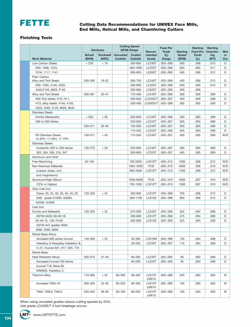
104www.LMTFETTE.com
Cutting Data Recommendations for UNIVEX Face Mills, End Mills, Helical Mills, and Chamfering Cutters
Finishing Tools
Cutting Speed Feed Per Starting StartingHardness (SFM) Range Recom- Tooth Starting Feed Per Chamfer- Wet
Brinell Rockwell Uncoated Coated mended (fZ) Speed Tooth ing orWork Material (BHN) (HRC) Carbide Carbide Grade Range (SFM) (fZ) (IPT) Dry
Low Carbon Steels < 220 < 19 350-800 LC240T .003-.009 500 .006 .013 D
AISI: 1008, 1010, 400-1000 LC225T .003-.008 650 .005 .011 D
1018, 1117, 1141 300-650 LC630T .003-.009 450 .006 .012 D
Plain Carbon, Alloy and Tool Steels 200-300 19-32 300-700 LC240T .003-.009 450 .006 .013 D
AISI: 1045, 4140, 4320, 300-900 LC225T .003-.008 550 .005 .013 D
4340,5120, 8620, P-20 300-600 LC630T .003-.009 400 .006
Alloy and Tool Steels 300-381 32-41 175-400 LC240T .003-.008 300 .005 .009 D
AISI Tool steels: H10, H11, 250-650 LC225S/T .003-.007 450 .005 .008 D
H13, alloy steels: 4140, 4150, 200-400 LC630S/T .003-.008 300 .005 .009 D
4320, 4340, 5120, 8620, 8640
Stainless Steels
Ferritic-Martensitic < 330 < 35 200-600 LC240T .003-.008 450 .005 .008 D
400 to 500 Series 250-650 LC225T .003-.007 500 .004 .008 D
330-371 35-40 150-500 LC240T .003-.007 350 .005 .008 D
175-550 LC225T .003-.006 425 .004 .008 D
PH Stainless Steels 150-371 < 40 175-500 LC240T .003-.007 400 .005 .008 W/D15-5PH, 17-4PH, 17-7PH
Stainless Steels
Austenitic 200 to 300 Series 135-275 < 29 250-600 LC240T .003-.007 400 .005 .008 D
303, 304, 306, 316, 347 300-800 LC225T .003-.007 450 .005 .008 D
Aluminum and other
Free-Machining 50-150 700-2000 LC610T• .003-.012 1000 .008 .012 W/D
Non-fererrous Materials 1000-12000 PCD .003-.010 4000 .006 .010 W/D
(copper, brass, zinc 900-4000 LC610T• .003-.010 1500 .008 .012 W/D
and magnesium)
Aluminum/High-Silicon 1000-6000 PCD .003-.010 4000 .007 .010 W/D
(12% or Higher) 700-1500 LC610T• .003-.010 1000 .007 .010 W/D
Grey Cast Iron
Class: 20, 25, 30, 35, 40, 45, 50 120-320 < 34 300-900 LC610T .003-.008 700 .006 .012 D
SAE: grade G1800, G3000, 300-1100 LC615E .003-.008 850 .006 .012 D
G3500, G4000
Cast Iron
Ductile and Malleable 120-320 < 34 275-500 LC240T .003-.006 325 .004 .008 D
ASTM A536: 60-40-18, 300-600 LC610T .003-.006 475 .004 .008 D
65-45-12, 100-70-06 300-800 LC612E .003-.006 525 .004 .008 D
ASTM A47 grades 3000,
4000, 5000, 6000
Nickel-Base Alloys
Annealed 600 series Inconel 140-300 < 32 50-300 LC610M .003-.006 130 .004 .008 D
Hastelloy & Waspaloy-Hastelloy B, 50-250 LC240T .003-.007 110 .004 .008 D
C-27, Inconel 601, 617, 625, 718
Nickel-Base,
Heat Resistant Alloys 300-475 31-49 60-200 LC240T .002-.005 90 .003 .008 D
Annealed Inconel 700 Series 60-200 LC225T .002-.005 95 .003 .008 D
Inconel 718, Rena 95,
MA6000, Hastelloy C
Titanium-Alloy 110-300 < 32 60-300 90-400 LC610T .003-.006 220 .003 .005 WLW610
Annealed Ti6Al-4V 300-350 32-36 60-220 90-300 LC610T .002-.006 150 .003 .005 WLW610
Ti6Al, Ti98.8, Ti99.9 350-440 36-46 60-180 90-200 LC610T .003-.006 130 .003 .005 WLW610
When using uncoated grades reduce cutting speeds by 25%. Use grade LC240S/T if tool breakage occurs.
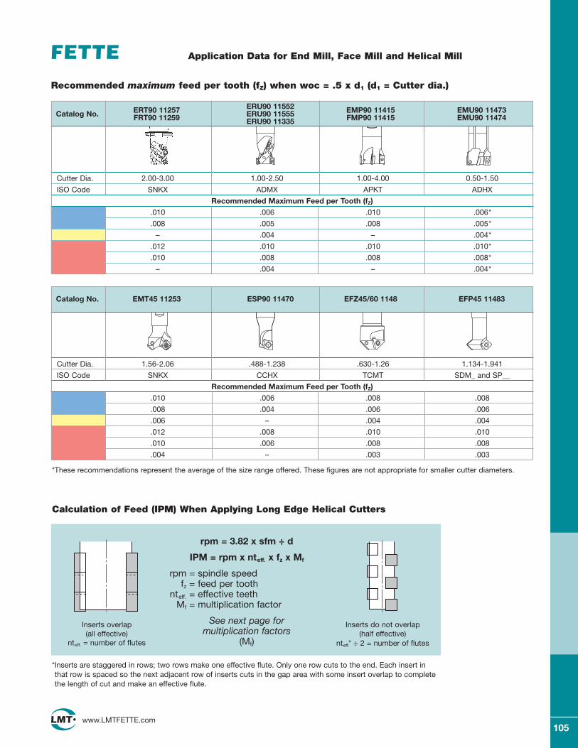
105www.LMTFETTE.com
Application Data for End Mill, Face Mill and Helical Mill
*Inserts are staggered in rows; two rows make one effective flute. Only one row cuts to the end. Each insert inthat row is spaced so the next adjacent row of inserts cuts in the gap area with some insert overlap to completethe length of cut and make an effective flute.
Inserts overlap (all effective)
nteff. = number of flutes
Inserts do not overlap (half effective)
nteff.* ÷ 2 = number of flutes
rpm = 3.82 x sfm ÷ d
IPM = rpm x nteff. x fz x Mf
rpm = spindle speedfz = feed per tooth
nteff. = effective teethMf = multiplication factor
See next page formultiplication factors
(Mf)
Calculation of Feed (IPM) When Applying Long Edge Helical Cutters
Cutter Dia. 2.00-3.00 1.00-2.50 1.00-4.00 0.50-1.50
ISO Code SNKX ADMX APKT ADHX
Recommended Maximum Feed per Tooth (fZ)
.010 .006 .010 .006*
.008 .005 .008 .005*
– .004 – .004*
.012 .010 .010 .010*
.010 .008 .008 .008*
– .004 – .004*
ERT90 11257 ERU90 11552 EMP90 11415 EMU90 11473Catalog No. FRT90 11259 ERU90 11555 FMP90 11415 EMU90 11474ERU90 11335
Recommended maximum feed per tooth (fZ) when woc = .5 x d1 (d1 = Cutter dia.)
Cutter Dia. 1.56-2.06 .488-1.238 .630-1.26 1.134-1.941
ISO Code SNKX CCHX TCMT SDM_ and SP__
Recommended Maximum Feed per Tooth (fZ)
.010 .006 .008 .008
.008 .004 .006 .006
.006 – .004 .004
.012 .008 .010 .010
.010 .006 .008 .008
.004 – .003 .003
Catalog No. EMT45 11253 ESP90 11470 EFZ45/60 1148 EFP45 11483
*These recommendations represent the average of the size range offered. These figures are not appropriate for smaller cutter diameters.
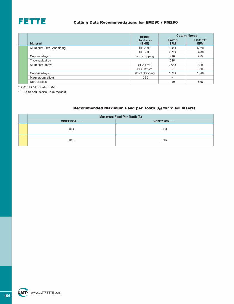
106www.LMTFETTE.com
Cutting Data Recommendations for EMZ90 / FMZ90
Brinell Cutting Speed
Hardness LW610 LC610T*Material (BHN) SFM SFMAluminum Free Machining HB < 80 3280 4920
HB > 80 2620 3280Copper alloys long chipping 820 985Thermoplastics 985 –Aluminum alloys Si < 12% 2620 328
Si ≥ 12%** – 650Copper alloys short chipping 1320 1640Magnesium alloys 1320 –Duroplastics 490 650
Recommended Maximum Feed per Tooth (fZ) for V_GT Inserts
Maximum Feed Per Tooth (fZ)
VPGT1604 . . . VCGT2205 . . .
.014 .020
.012 .016
*LC610T CVD Coated TiAlN
**PCD-tipped inserts upon request.
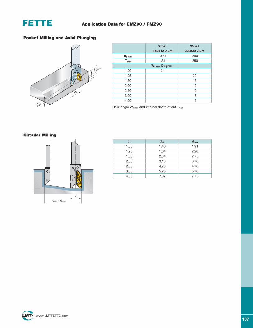
107www.LMTFETTE.com
Application Data for EMZ90 / FMZ90
dmin – dmax
d1
d1
ap max
w1
Tmax
Pocket Milling and Axial Plunging
Circular Milling
VPGT VCGT
160412-ALM 220530-ALM
ap max .531 .590
Tmax .31 .350
W1 max Degree
1.00 24
1.25 22
1.50 15
2.00 12
2.50 9
3.00 7
4.00 5
d1 dmin dmax
1.00 1.40 1.91
1.25 1.64 2.26
1.50 2.34 2.75
2.00 3.18 3.76
2.50 4.23 4.76
3.00 5.28 5.76
4.00 7.07 7.75
Helix angle W1 max and internal depth of cut Tmax
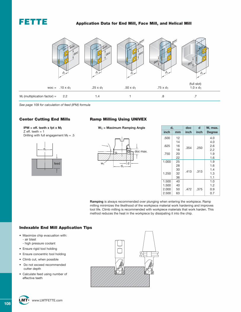
108www.LMTFETTE.com
feed
d1
d1
doc
woc
d1 d1 d1 d1
doc doc
docdoc
wocwoc
woc
woc
Ramping is always recommended over plunging when entering the workpiece. Rampmilling minimizes the likelihood of the workpiece material work hardening and improvestool life. Climb milling is recommended with workpiece materials that work harden. Thismethod reduces the heat in the workpiece by dissipating it into the chip.
Center Cutting End Mills
IPM = eff. teeth x fpt x MfZ eff. teeth = 1Drilling with full engagement Mf = .5
d1 doc d W1 max.inch mm inch inch Degree
.500 12 4.014 4.0
.625 16 2.618
.354 .2502.2
.750 20 1.922 1.6
1.000 25 1.928 1.630 1.4
1.250 32.413 .313
1.336 1.1
1.500 40 1.01.500 40 1.22.000 50 .472 .375 0.92.500 63 0.7
(full slot)woc = .10 x d1 .25 x d1 .50 x d1 .75 x d1 1.0 x d1
Mf (multiplication factor) = 2.2 1.4 1 .8 .7
Ramp Milling Using UNIVEX
W1 = Maximum Ramping Angle
doc max.
dd1
w1
Indexable End Mill Application Tips
• Maximize chip evacuation with:- air blast- high pressure coolant
• Ensure rigid tool holding
• Ensure concentric tool holding
• Climb cut, when possible
• Do not exceed recommended cutter depth
• Calculate feed using number of effective teeth
See page 109 for calculation of feed (IPM) formula
Application Data for End Mill, Face Mill, and Helical Mill
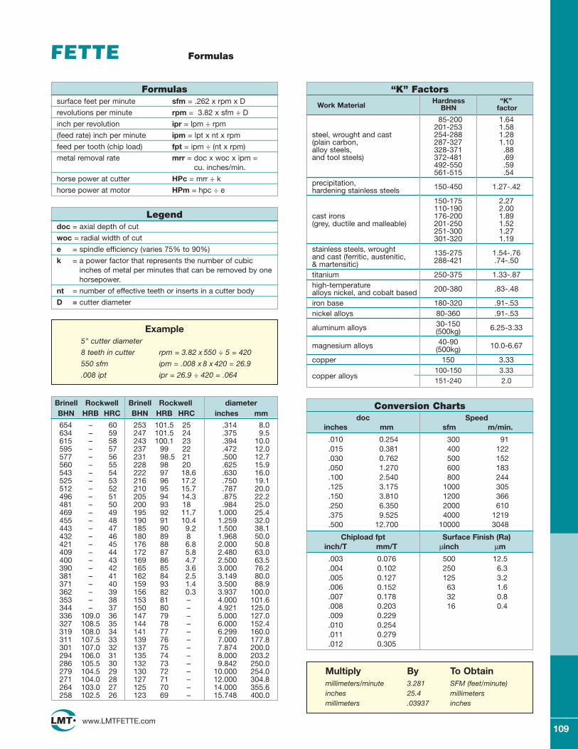
109www.LMTFETTE.com
Formulas
Hardness “K”BHN factorWork Material
“K” FactorsFormulassurface feet per minute sfm = .262 x rpm x D
revolutions per minute rpm = 3.82 x sfm ÷ D
inch per revolution ipr = lpm ÷ rpm
(feed rate) inch per minute ipm = lpt x nt x rpm
feed per tooth (chip load) fpt = ipm ÷ (nt x rpm)
metal removal rate mrr = doc x woc x ipm =cu. inches/min.
horse power at cutter HPc = mrr ÷ k
horse power at motor HPm = hpc ÷ e
Example5" cutter diameter
8 teeth in cutter rpm = 3.82 x 550 ÷ 5 = 420
550 sfm ipm = .008 x 8 x 420 = 26.9
.008 ipt ipr = 26.9 ÷ 420 = .064
Brinell RockwellBHN HRB HRC
253 101.5 25247 101.5 24243 100.1 23237 99 22231 98.5 21228 98 20222 97 18.6216 96 17.2210 95 15.7205 94 14.3200 93 18195 92 11.7190 91 10.4185 90 9.2180 89 8176 88 6.8172 87 5.8169 86 4.7165 85 3.6162 84 2.5159 93 1.4156 82 0.3153 81 –150 80 –147 79 –144 78 –141 77 –139 76 –137 75 –135 74 –132 73 –130 72 –127 71 –125 70 –123 69 –
diameterinches mm
.314 8.0
.375 9.5
.394 10.0
.472 12.0
.500 12.7
.625 15.9
.630 16.0
.750 19.1
.787 20.0
.875 22.2
.984 25.01.000 25.41.259 32.01.500 38.11.968 50.02.000 50.82.480 63.02.500 63.53.000 76.23.149 80.03.500 88.93.937 100.04.000 101.64.921 125.05.000 127.06.000 152.46.299 160.07.000 177.87.874 200.08.000 203.29.842 250.0
10.000 254.012.000 304.814.000 355.615.748 400.0
Legenddoc = axial depth of cut
woc = radial width of cut
e = spindle efficiency (varies 75% to 90%)
k = a power factor that represents the number of cubicinches of metal per minutes that can be removed by onehorsepower.
nt = number of effective teeth or inserts in a cutter body
D = cutter diameter
Brinell RockwellBHN HRB HRC
654 – 60634 – 59615 – 58595 – 57577 – 56560 – 55543 – 54525 – 53512 – 52496 – 51481 – 50469 – 49455 – 48443 – 47432 – 46421 – 45409 – 44400 – 43390 – 42381 – 41371 – 40362 – 39353 – 38344 – 37336 109.0 36327 108.5 35319 108.0 34311 107.5 33301 107.0 32294 106.0 31286 105.5 30279 104.5 29271 104.0 28264 103.0 27258 102.5 26
Multiply By To Obtainmillimeters/minute 3.281 SFM (feet/minute)inches 25.4 millimetersmillimeters .03937 inches
85-200 1.64201-253 1.58
steel, wrought and cast 254-288 1.28(plain carbon, 287-327 1.10alloy steels, 328-371 .88and tool steels) 372-481 .69
492-550 .59561-515 .54
precipitation, 150-450 1.27-.42hardening stainless steels150-175 2.27110-190 2.00
cast irons 176-200 1.89(grey, ductile and malleable) 201-250 1.52
251-300 1.27301-320 1.19
stainless steels, wrought 135-275 1.54-.76 and cast (ferritic, austenitic, 288-421 .74-.50 & martensitic)titanium 250-375 1.33-.87high-temperature 200-380 .83-.48 alloys nickel, and cobalt basediron base 180-320 .91-.53nickel alloys 80-360 .91-.53
aluminum alloys 30-150 6.25-3.33(500kg)
magnesium alloys 40-90 10.0-6.67(500kg)copper 150 3.33
copper alloys100-150 3.33151-240 2.0
Conversion Chartsdoc
inches mm
.010 0.254
.015 0.381
.030 0.762
.050 1.270
.100 2.540
.125 3.175
.150 3.810
.250 6.350
.375 9.525
.500 12.700
Speedsfm m/min.
300 91400 122500 152600 183800 244
1000 3051200 3662000 6104000 1219
10000 3048
Chipload fptinch/T mm/T
.003 0.076
.004 0.102
.005 0.127
.006 0.152
.007 0.178
.008 0.203
.009 0.229
.010 0.254
.011 0.279
.012 0.305
Surface Finish (Ra)μinch μm
500 12.5250 6.3125 3.263 1.632 0.816 0.4
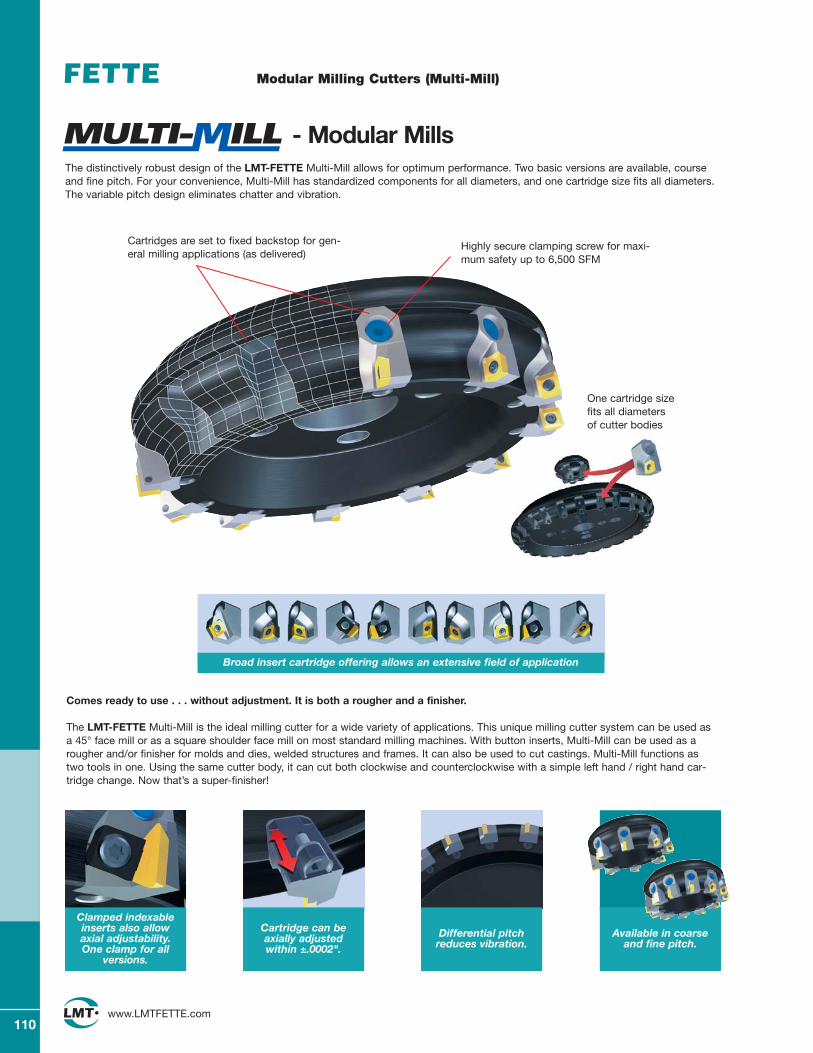
110www.LMTFETTE.com
Cartridges are set to fixed backstop for gen-eral milling applications (as delivered)
Highly secure clamping screw for maxi-mum safety up to 6,500 SFM
One cartridge size fits all diameters of cutter bodies
The distinctively robust design of the LMT-FETTE Multi-Mill allows for optimum performance. Two basic versions are available, courseand fine pitch. For your convenience, Multi-Mill has standardized components for all diameters, and one cartridge size fits all diameters. The variable pitch design eliminates chatter and vibration.
Broad insert cartridge offering allows an extensive field of application
- Modular Mills
Differential pitch reduces vibration.
Comes ready to use . . . without adjustment. It is both a rougher and a finisher.
The LMT-FETTE Multi-Mill is the ideal milling cutter for a wide variety of applications. This unique milling cutter system can be used asa 45° face mill or as a square shoulder face mill on most standard milling machines. With button inserts, Multi-Mill can be used as arougher and/or finisher for molds and dies, welded structures and frames. It can also be used to cut castings. Multi-Mill functions astwo tools in one. Using the same cutter body, it can cut both clockwise and counterclockwise with a simple left hand / right hand car-tridge change. Now that’s a super-finisher!
Clamped indexableinserts also allowaxial adjustability. One clamp for all
versions.
Available in coarse and fine pitch.
Cartridge can be axially adjusted within ±.0002".
Modular Milling Cutters (Multi-Mill)
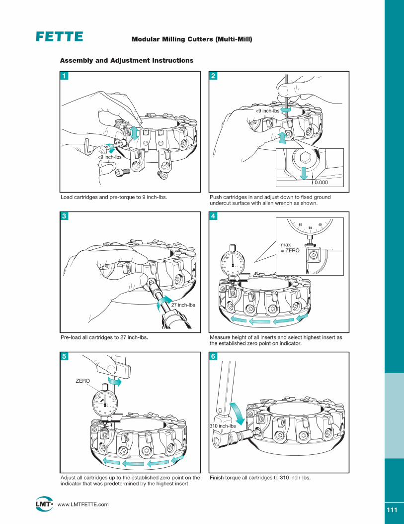
111www.LMTFETTE.com
Modular Milling Cutters (Multi-Mill)
Assembly and Adjustment Instructions
Load cartridges and pre-torque to 9 inch-lbs.
1
Push cartridges in and adjust down to fixed ground undercut surface with allen wrench as shown.
2
Pre-load all cartridges to 27 inch-lbs.
3
Measure height of all inserts and select highest insert as the established zero point on indicator.
4
Adjust all cartridges up to the established zero point on theindicator that was predetermined by the highest insert
5
Finish torque all cartridges to 310 inch-lbs.
6
ZERO
max= ZERO
0.000
<9 inch-lbs
<9 inch-lbs
27 inch-lbs
310 inch-lbs
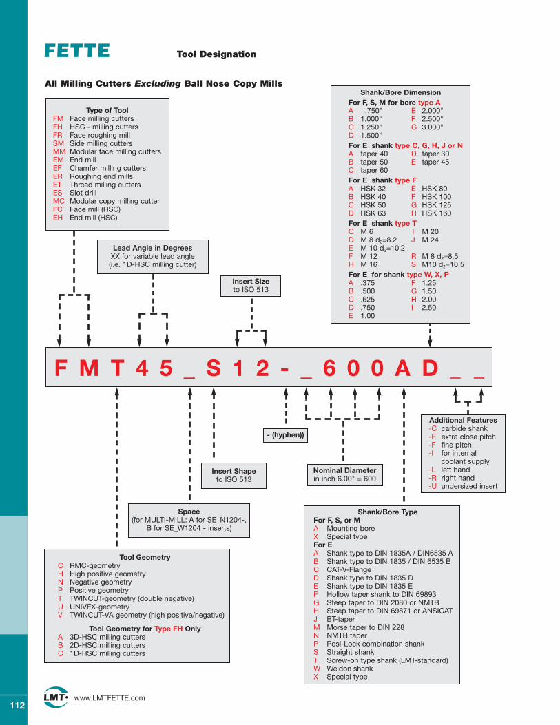
112www.LMTFETTE.com
Tool Designation
F M T 4 5 _ S 1 2 - _ 6 0 0 A D _ _
Lead Angle in DegreesXX for variable lead angle (i.e. 1D-HSC milling cutter)
Insert Shape to ISO 513
Insert Size to ISO 513
Shank/Bore TypeFor F, S, or M A Mounting boreX Special typeFor EA Shank type to DIN 1835A / DIN6535 AB Shank type to DIN 1835 / DIN 6535 BC CAT-V-FlangeD Shank type to DIN 1835 DE Shank type to DIN 1835 EF Hollow taper shank to DIN 69893G Steep taper to DIN 2080 or NMTBH Steep taper to DIN 69871 or ANSICATJ BT-taperM Morse taper to DIN 228N NMTB taperP Posi-Lock combination shankS Straight shankT Screw-on type shank (LMT-standard)W Weldon shankX Special type
All Milling Cutters Excluding Ball Nose Copy Mills
- (hyphen))
Shank/Bore DimensionFor F, S, M for bore type AA .750" E 2.000"B 1.000" F 2.500"C 1.250" G 3.000"D 1.500" For E shank type C, G, H, J or NA taper 40 D taper 30B taper 50 E taper 45C taper 60For E shank type FA HSK 32 E HSK 80B HSK 40 F HSK 100C HSK 50 G HSK 125D HSK 63 H HSK 160For E shank type TC M 6 I M 20D M 8 d2=8.2 J M 24E M 10 d2=10.2F M 12 R M 8 d2=8.5H M 16 S M10 d2=10.5For E for shank type W, X, PA .375 F 1.25B .500 G 1.50C .625 H 2.00D .750 I 2.50E 1.00
Tool GeometryC RMC-geometryH High positive geometryN Negative geometryP Positive geometryT TWINCUT-geometry (double negative)U UNIVEX-geometryV TWINCUT-VA geometry (high positive/negative)
Tool Geometry for Type FH OnlyA 3D-HSC milling cuttersB 2D-HSC milling cuttersC 1D-HSC milling cutters
Space(for MULTI-MILL: A for SE_N1204-,
B for SE_W1204 - inserts)
Nominal Diameter in inch 6.00" = 600
Additional Features-C carbide shank-E extra close pitch-F fine pitch-I for internal
coolant supply-L left hand-R right hand-U undersized insert
Type of ToolFM Face milling cuttersFH HSC - milling cuttersFR Face roughing millSM Side milling cuttersMM Modular face milling cuttersEM End millEF Chamfer milling cuttersER Roughing end millsET Thread milling cuttersES Slot drillMC Modular copy milling cutterFC Face mill (HSC)EH End mill (HSC)
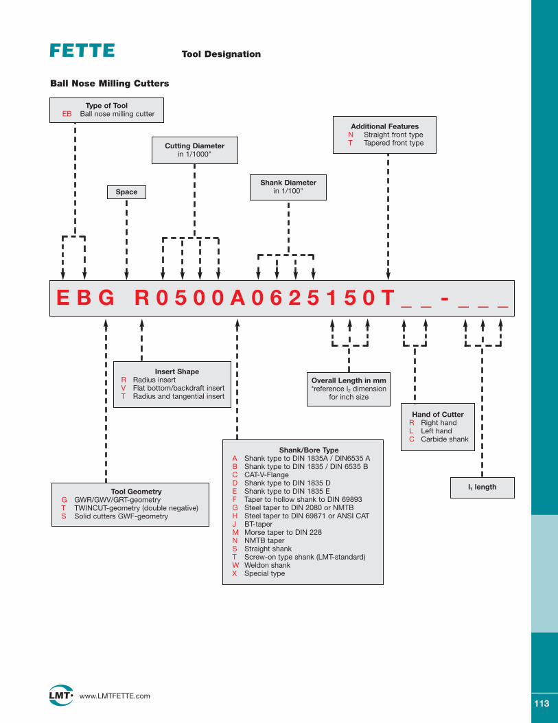
113www.LMTFETTE.com
Tool Designation
E B G R 0 5 0 0 A 0 6 2 5 1 5 0 T _ _ - _ _ _
Type of ToolEB Ball nose milling cutter
Tool GeometryG GWR/GWV/GRT-geometryT TWINCUT-geometry (double negative)S Solid cutters GWF-geometry
Insert ShapeR Radius insertV Flat bottom/backdraft insertT Radius and tangential insert
Shank/Bore TypeA Shank type to DIN 1835A / DIN6535 AB Shank type to DIN 1835 / DIN 6535 BC CAT-V-FlangeD Shank type to DIN 1835 DE Shank type to DIN 1835 EF Taper to hollow shank to DIN 69893G Steel taper to DIN 2080 or NMTBH Steel taper to DIN 69871 or ANSI CATJ BT-taperM Morse taper to DIN 228N NMTB taperS Straight shankT Screw-on type shank (LMT-standard)W Weldon shankX Special type
Ball Nose Milling Cutters
Overall Length in mm*reference l2 dimension
for inch size
Additional FeaturesN Straight front type T Tapered front type
Space
Cutting Diameter in 1/1000"
Shank Diameter in 1/100"
Hand of CutterR Right handL Left handC Carbide shank
l1 length
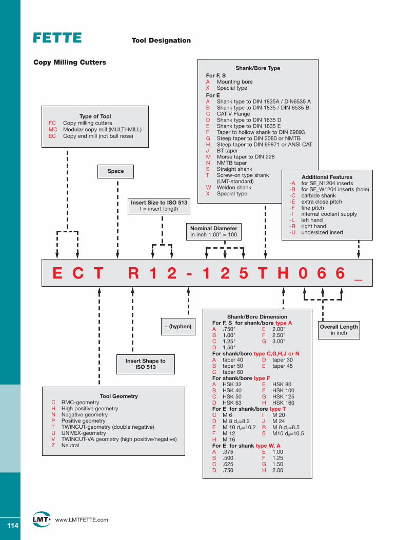
114www.LMTFETTE.com
Tool Designation
Copy Milling Cutters
E C T R 1 2 - 1 2 5 T H 0 6 6 _
Type of ToolFC Copy milling cuttersMC Modular copy mill (MULTI-MILL) EC Copy end mill (not ball nose)
Tool GeometryC RMC-geometryH High positive geometryN Negative geometryP Positive geometryT TWINCUT-geometry (double negative)U UNIVEX-geometryV TWINCUT-VA geometry (high positive/negative)Z Neutral
Insert Shape to ISO 513
- (hyphen)
Space
Shank/Bore DimensionFor F, S for shank/bore type AA .750" E 2.00"B 1.00" F 2.50"C 1.25" G 3.00"D 1.50"For shank/bore type C,G,H,J or NA taper 40 D taper 30B taper 50 E taper 45C taper 60For shank/bore type FA HSK 32 E HSK 80B HSK 40 F HSK 100C HSK 50 G HSK 125D HSK 63 H HSK 160For E for shank/bore type TC M 6 I M 20D M 8 d2=8.2 J M 24E M 10 d2=10.2 R M 8 d2=8.5F M 12 S M10 d2=10.5H M 16For E for shank type W, AA .375 E 1.00B .500 F 1.25C .625 G 1.50D .750 H 2.00
Nominal Diameterin inch 1.00" = 100
Insert Size to ISO 513I = insert length
Overall Length in inch
Shank/Bore TypeFor F, S A Mounting boreX Special typeFor EA Shank type to DIN 1835A / DIN6535 AB Shank type to DIN 1835 / DIN 6535 BC CAT-V-FlangeD Shank type to DIN 1835 DE Shank type to DIN 1835 EF Taper to hollow shank to DIN 69893G Steep taper to DIN 2080 or NMTBH Steep taper to DIN 69871 or ANSI CATJ BT-taperM Morse taper to DIN 228N NMTB taperS Straight shankT Screw-on type shank
(LMT-standard)W Weldon shankX Special type
Additional Features-A for SE_N1204 inserts-B for SE_W1204 inserts (hole)-C carbide shank-E extra close pitch-F fine pitch-I internal coolant supply-L left hand-R right hand-U undersized insert
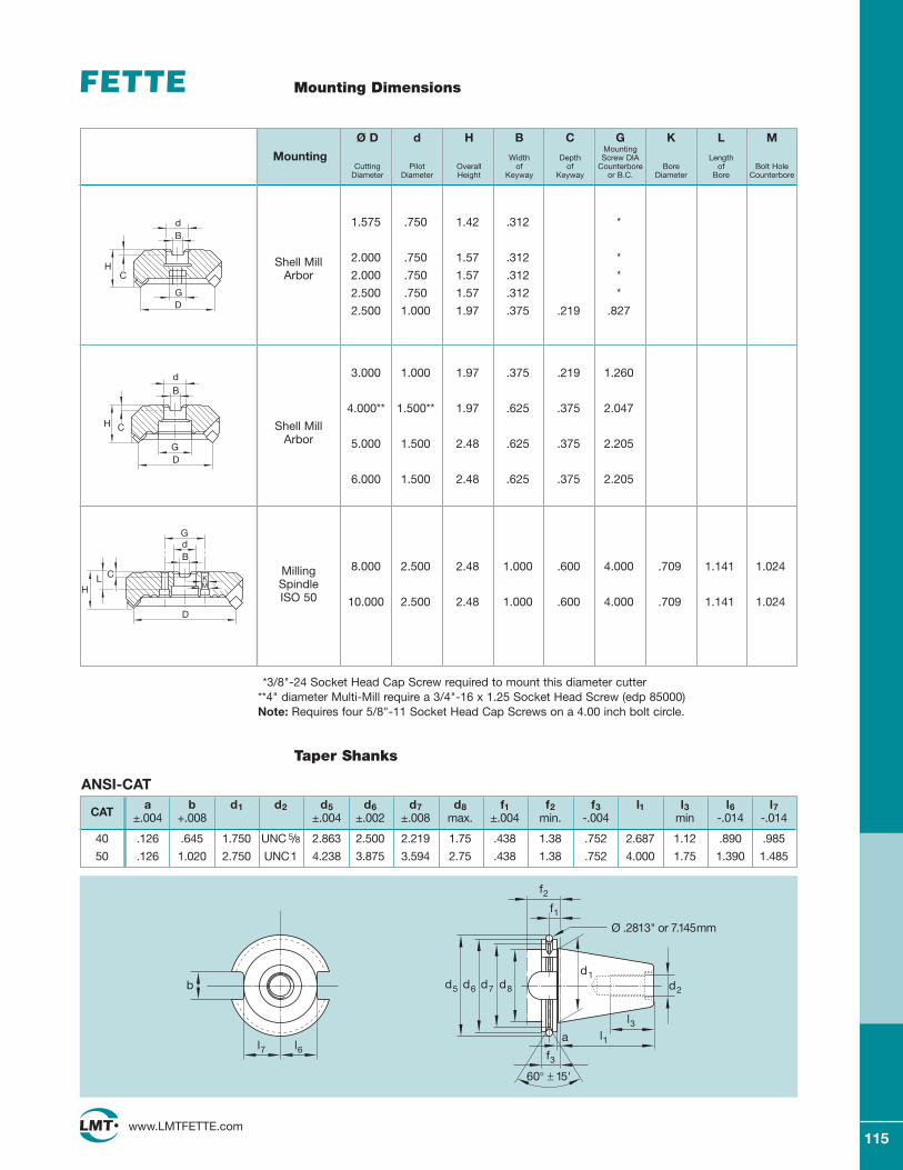
115www.LMTFETTE.com
Mounting Dimensions
DG
CH
dB
GD
CH
dB
D
CLH
dB
G
MK
1.575 .750 1.42 .312 *
Shell Mill 2.000 .750 1.57 .312 *
Arbor 2.000 .750 1.57 .312 *
2.500 .750 1.57 .312 *
2.500 1.000 1.97 .375 .219 .827
3.000 1.000 1.97 .375 .219 1.260
4.000** 1.500** 1.97 .625 .375 2.047
Shell MillArbor 5.000 1.500 2.48 .625 .375 2.205
6.000 1.500 2.48 .625 .375 2.205
Milling 8.000 2.500 2.48 1.000 .600 4.000 .709 1.141 1.024
SpindleISO 50 10.000 2.500 2.48 1.000 .600 4.000 .709 1.141 1.024
Ø D d H B C G K L MMounting
Mounting Width Depth Screw DIA LengthCutting Pilot Overall of of Counterbore Bore of Bolt Hole
Diameter Diameter Height Keyway Keyway or B.C. Diameter Bore Counterbore
ANSI-CAT
CATa b d1 d2 d5 d6 d7 d8 f1 f2 f3 l1 l3 l6 l7
±.004 +.008 ±.004 ±.002 ±.008 max. ±.004 min. -.004 min -.014 -.014
40 .126 .645 1.750 UNC 5/8 2.863 2.500 2.219 1.75 .438 1.38 .752 2.687 1.12 .890 .985
50 .126 1.020 2.750 UNC1 4.238 3.875 3.594 2.75 .438 1.38 .752 4.000 1.75 1.390 1.485
b
l7 l6
d2
f3
a l1
l3
d1
60° ± 15'
d8d7d6d5
f1
f2
Ø .2813" or 7.145mm
*3/8"-24 Socket Head Cap Screw required to mount this diameter cutter**4" diameter Multi-Mill require a 3/4"-16 x 1.25 Socket Head Screw (edp 85000)Note: Requires four 5/8"-11 Socket Head Cap Screws on a 4.00 inch bolt circle.
Taper Shanks
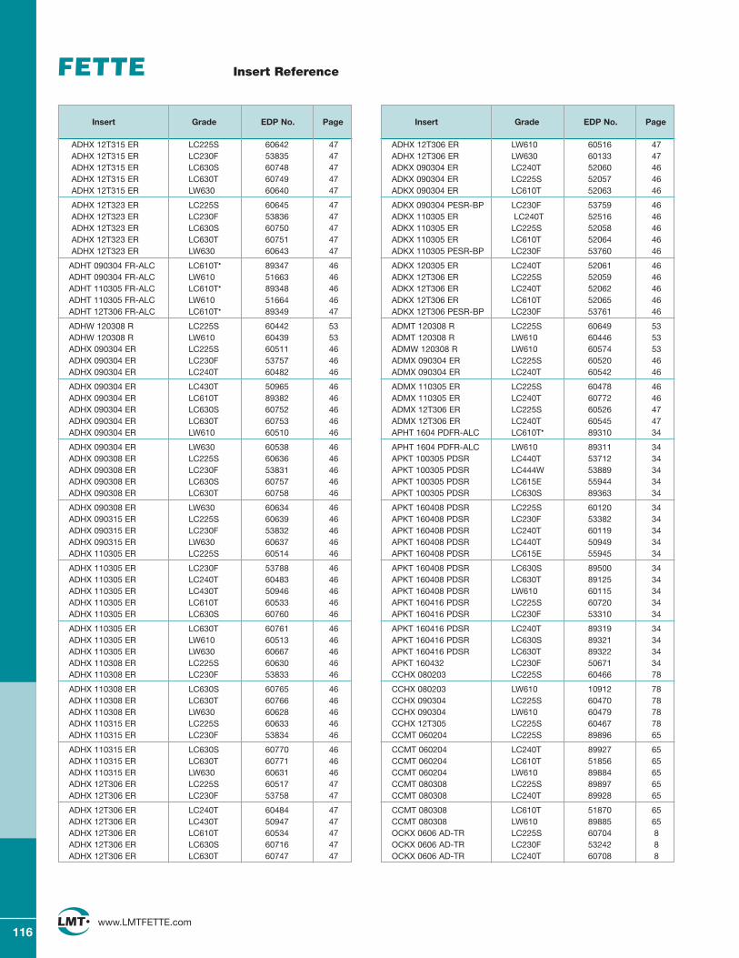
116www.LMTFETTE.com
Insert Reference
Insert Grade EDP No. Page
ADHX 12T315 ER LC225S 60642 47ADHX 12T315 ER LC230F 53835 47ADHX 12T315 ER LC630S 60748 47ADHX 12T315 ER LC630T 60749 47ADHX 12T315 ER LW630 60640 47
ADHX 12T323 ER LC225S 60645 47ADHX 12T323 ER LC230F 53836 47ADHX 12T323 ER LC630S 60750 47ADHX 12T323 ER LC630T 60751 47ADHX 12T323 ER LW630 60643 47
ADHT 090304 FR-ALC LC610T• 89347 46ADHT 090304 FR-ALC LW610 51663 46ADHT 110305 FR-ALC LC610T• 89348 46ADHT 110305 FR-ALC LW610 51664 46ADHT 12T306 FR-ALC LC610T• 89349 47
ADHW 120308 R LC225S 60442 53ADHW 120308 R LW610 60439 53ADHX 090304 ER LC225S 60511 46ADHX 090304 ER LC230F 53757 46ADHX 090304 ER LC240T 60482 46
ADHX 090304 ER LC430T 50965 46ADHX 090304 ER LC610T 89382 46ADHX 090304 ER LC630S 60752 46ADHX 090304 ER LC630T 60753 46ADHX 090304 ER LW610 60510 46
ADHX 090304 ER LW630 60538 46ADHX 090308 ER LC225S 60636 46ADHX 090308 ER LC230F 53831 46ADHX 090308 ER LC630S 60757 46ADHX 090308 ER LC630T 60758 46
ADHX 090308 ER LW630 60634 46ADHX 090315 ER LC225S 60639 46ADHX 090315 ER LC230F 53832 46ADHX 090315 ER LW630 60637 46ADHX 110305 ER LC225S 60514 46
ADHX 110305 ER LC230F 53788 46ADHX 110305 ER LC240T 60483 46ADHX 110305 ER LC430T 50946 46ADHX 110305 ER LC610T 60533 46ADHX 110305 ER LC630S 60760 46
ADHX 110305 ER LC630T 60761 46ADHX 110305 ER LW610 60513 46ADHX 110305 ER LW630 60667 46ADHX 110308 ER LC225S 60630 46ADHX 110308 ER LC230F 53833 46
ADHX 110308 ER LC630S 60765 46ADHX 110308 ER LC630T 60766 46ADHX 110308 ER LW630 60628 46ADHX 110315 ER LC225S 60633 46ADHX 110315 ER LC230F 53834 46
ADHX 110315 ER LC630S 60770 46ADHX 110315 ER LC630T 60771 46ADHX 110315 ER LW630 60631 46ADHX 12T306 ER LC225S 60517 47ADHX 12T306 ER LC230F 53758 47
ADHX 12T306 ER LC240T 60484 47ADHX 12T306 ER LC430T 50947 47ADHX 12T306 ER LC610T 60534 47ADHX 12T306 ER LC630S 60716 47ADHX 12T306 ER LC630T 60747 47
Insert Grade EDP No. Page
ADHX 12T306 ER LW610 60516 47ADHX 12T306 ER LW630 60133 47ADKX 090304 ER LC240T 52060 46ADKX 090304 ER LC225S 52057 46ADKX 090304 ER LC610T 52063 46
ADKX 090304 PESR-BP LC230F 53759 46ADKX 110305 ER LC240T 52516 46ADKX 110305 ER LC225S 52058 46ADKX 110305 ER LC610T 52064 46ADKX 110305 PESR-BP LC230F 53760 46
ADKX 120305 ER LC240T 52061 46ADKX 12T306 ER LC225S 52059 46ADKX 12T306 ER LC240T 52062 46ADKX 12T306 ER LC610T 52065 46ADKX 12T306 PESR-BP LC230F 53761 46
ADMT 120308 R LC225S 60649 53ADMT 120308 R LW610 60446 53ADMW 120308 R LW610 60574 53ADMX 090304 ER LC225S 60520 46ADMX 090304 ER LC240T 60542 46
ADMX 110305 ER LC225S 60478 46ADMX 110305 ER LC240T 60772 46ADMX 12T306 ER LC225S 60526 47ADMX 12T306 ER LC240T 60545 47APHT 1604 PDFR-ALC LC610T• 89310 34
APHT 1604 PDFR-ALC LW610 89311 34APKT 100305 PDSR LC440T 53712 34APKT 100305 PDSR LC444W 53889 34APKT 100305 PDSR LC615E 55944 34APKT 100305 PDSR LC630S 89363 34
APKT 160408 PDSR LC225S 60120 34APKT 160408 PDSR LC230F 53382 34APKT 160408 PDSR LC240T 60119 34APKT 160408 PDSR LC440T 50949 34APKT 160408 PDSR LC615E 55945 34
APKT 160408 PDSR LC630S 89500 34APKT 160408 PDSR LC630T 89125 34APKT 160408 PDSR LW610 60115 34APKT 160416 PDSR LC225S 60720 34APKT 160416 PDSR LC230F 53310 34
APKT 160416 PDSR LC240T 89319 34APKT 160416 PDSR LC630S 89321 34APKT 160416 PDSR LC630T 89322 34APKT 160432 LC230F 50671 34CCHX 080203 LC225S 60466 78
CCHX 080203 LW610 10912 78CCHX 090304 LC225S 60470 78CCHX 090304 LW610 60479 78CCHX 12T305 LC225S 60467 78CCMT 060204 LC225S 89896 65
CCMT 060204 LC240T 89927 65CCMT 060204 LC610T 51856 65CCMT 060204 LW610 89884 65CCMT 080308 LC225S 89897 65CCMT 080308 LC240T 89928 65
CCMT 080308 LC610T 51870 65CCMT 080308 LW610 89885 65OCKX 0606 AD-TR LC225S 60704 8OCKX 0606 AD-TR LC230F 53242 8OCKX 0606 AD-TR LC240T 60708 8
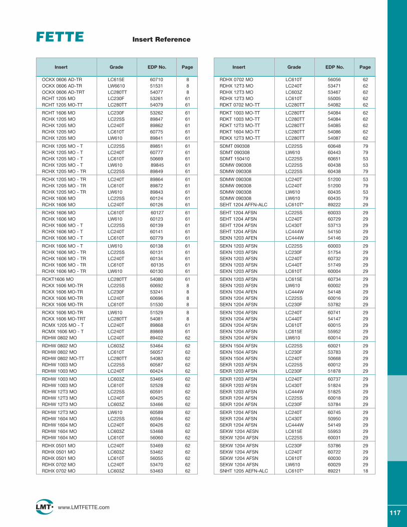
117www.LMTFETTE.com
Insert Reference
Insert Grade EDP No. Page
OCKX 0606 AD-TR LC615E 60710 8OCKX 0606 AD-TR LW6610 51531 8OCKX 0606 AD-TRT LC280TT 54077 8RCHT 1205 MO LC230F 53261 61RCHT 1205 MO-TT LC280TT 54079 61
RCHT 1606 MO LC230F 53262 61RCHX 1205 MO LC225S 89847 61RCHX 1205 MO LC240T 89862 61RCHX 1205 MO LC610T 60775 61RCHX 1205 MO LW610 89841 61
RCHX 1205 MO - T LC225S 89851 61RCHX 1205 MO - T LC240T 60777 61RCHX 1205 MO - T LC610T 50669 61RCHX 1205 MO - T LW610 89845 61RCHX 1205 MO - TR LC225S 89849 61
RCHX 1205 MO - TR LC240T 89864 61RCHX 1205 MO - TR LC610T 89872 61RCHX 1205 MO - TR LW610 89843 61RCHX 1606 MO LC225S 60124 61RCHX 1606 MO LC240T 60126 61
RCHX 1606 MO LC610T 60127 61RCHX 1606 MO LW610 60123 61RCHX 1606 MO - T LC225S 60139 61RCHX 1606 MO - T LC240T 60141 61RCHX 1606 MO - T LC610T 60779 61
RCHX 1606 MO - T LW610 60138 61RCHX 1606 MO - TR LC225S 60131 61RCHX 1606 MO - TR LC240T 60134 61RCHX 1606 MO - TR LC610T 60135 61RCHX 1606 MO - TR LW610 60130 61
RCKT1606 MO LC280TT 54080 61RCKX 1606 MO-TR LC225S 60692 8RCKX 1606 MO-TR LC230F 53241 8RCKX 1606 MO-TR LC240T 60696 8RCKX 1606 MO-TR LC610T 51530 8
RCKX 1606 MO-TR LW610 51529 8RCKX 1606 MO-TRT LC280TT 54081 8RCMX 1205 MO - T LC240T 89868 61RCMX 1606 MO - T LC240T 89869 61RDHW 0802 MO LC240T 89402 62
RDHW 0802 MO LC603Z 53464 62RDHW 0802 MO LC610T 56057 62RDHW 0802 MO-TT LC280TT 54083 62RDHW 1003 MO LC225S 60587 62RDHW 1003 MO LC240T 60424 62
RDHW 1003 MO LC603Z 53465 62RDHW 1003 MO LC610T 52528 62RDHW 12T3 MO LC225S 60591 62RDHW 12T3 MO LC240T 60425 62RDHW 12T3 MO LC603Z 53466 62
RDHW 12T3 MO LW610 60589 62RDHW 1604 MO LC225S 60594 62RDHW 1604 MO LC240T 60426 62RDHW 1604 MO LC603Z 53468 62RDHW 1604 MO LC610T 56060 62
RDHX 0501 MO LC240T 53469 62RDHX 0501 MO LC603Z 53462 62RDHX 0501 MO LC610T 56055 62RDHX 0702 MO LC240T 53470 62RDHX 0702 MO LC603Z 53463 62
Insert Grade EDP No. Page
RDHX 0702 MO LC610T 56056 62RDHX 12T3 MO LC240T 53471 62RDHX 12T3 MO LC603Z 53467 62RDHX 12T3 MO LC610T 55005 62RDKT 0702 MO-TT LC280TT 54082 62
RDKT 1003 MO-TT LC280TT 54084 62RDKT 1003 MO-TT LC280TT 54084 62RDKT 12T3 MO-TT LC280TT 54085 62RDKT 1604 MO-TT LC280TT 54086 62RDKX 12T3 MO-TT LC280TT 54087 62
SDMT 090308 LC225S 60648 79SDMT 090308 LW610 60443 79SDMT 150410 LC225S 60651 53SDMW 090308 LC225S 60438 53SDMW 090308 LC225S 60438 79
SDMW 090308 LC240T 51200 53SDMW 090308 LC240T 51200 79SDMW 090308 LW610 60435 53SDMW 090308 LW610 60435 79SEHT 1204 AFFN-ALC LC610T• 89222 29
SEHT 1204 AFSN LC225S 60033 29SEHT 1204 AFSN LC240T 60729 29SEHT 1204 AFSN LC430T 53713 29SEHT 1204 AFSN LC444W 54150 29SEKN 1203 AFEN LC444W 54146 29
SEKN 1203 AFSN LC225S 60003 29SEKN 1203 AFSN LC230F 51754 29SEKN 1203 AFSN LC240T 60732 29SEKN 1203 AFSN LC440T 51749 29SEKN 1203 AFSN LC610T 60004 29
SEKN 1203 AFSN LC615E 60734 29SEKN 1203 AFSN LW610 60002 29SEKN 1204 AFEN LC444W 54148 29SEKN 1204 AFSN LC225S 60016 29SEKN 1204 AFSN LC230F 53782 29
SEKN 1204 AFSN LC240T 60741 29SEKN 1204 AFSN LC440T 54147 29SEKN 1204 AFSN LC610T 60015 29SEKN 1204 AFSN LC615E 55952 29SEKN 1204 AFSN LW610 60014 29
SEKN 1504 AFSN LC225S 60021 29SEKN 1504 AFSN LC230F 53783 29SEKN 1504 AFSN LC240T 50668 29SEKR 1203 AFSN LC225S 60012 29SEKR 1203 AFSN LC230F 51878 29
SEKR 1203 AFSN LC240T 60737 29SEKR 1203 AFSN LC430T 51824 29SEKR 1203 AFSN LC444W 51825 29SEKR 1204 AFSN LC225S 60018 29SEKR 1204 AFSN LC230F 53784 29
SEKR 1204 AFSN LC240T 60745 29SEKR 1204 AFSN LC430T 50950 29SEKR 1204 AFSN LC444W 54149 29SEKW 1204 AESN LC615E 55953 29SEKW 1204 AFSN LC225S 60031 29
SEKW 1204 AFSN LC230F 53786 29SEKW 1204 AFSN LC240T 60722 29SEKW 1204 AFSN LC610T 60030 29SEKW 1204 AFSN LW610 60029 29SNHT 1205 AEFN-ALC LC610T• 89221 18
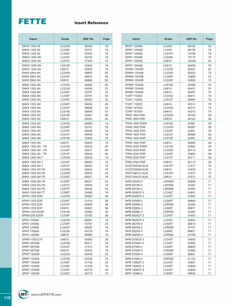
118www.LMTFETTE.com
Insert Reference
Insert Grade EDP No. Page
SNHX 1205 AE LC225S 60340 18SNHX 1205 AE LC230F 53787 18SNHX 1205 AE LC440T 50948 18SNKQ 1205 AN LC240T 50735 18SNKQ 1205 AN LC610T 51953 18
SNKQ 1205 AN LC615E 55954 18SNKQ 1205 AN LW610 60055 18SNKX 0904 AN LC225S 89892 65SNKX 0904 AN LC240T 88923 65SNKX 0904 AN LW610 89880 65
SNKX 1205 AN LC225S 60036 65SNKX 1205 AN LC225S 60036 53SNKX 1205 AN LC230F 53791 53SNKX 1205 AN LC230F 53791 65SNKX 1205 AN LC240T 60039 53
SNKX 1205 AN LC240T 60039 65SNKX 1205 AN LC610T 89936 53SNKX 1205 AN LC615E 89365 53SNKX 1205 AN LC615E 55961 65SNKX 1205 AN LW610 60035 65
SNKX 1205 AN LC225S 60036 18SNKX 1205 AN LC230F 53791 18SNKX 1205 AN LC240T 60039 18SNKX 1205 AN LC610T 89936 18SNKX 1205 AN LC615E 55955 18
SNKX 1205 AN LW610 60035 18SNKX 1205 AN - TR LC225S 60045 65SNKX 1205 AN - TR LC240T 60047 65SNKX 1205 AN - TR LC610T 60048 65SNKX 1205 AN-T LC225S 60050 18
SNKX 1205 AN-T LC240T 60053 18SNKX 1205 AN-T LC610T 60054 18SNKX 1205 AN-TR LC225S 60045 18SNKX 1205 AN-TR LC225S 60045 53SNKX 1205 AN-TR LC240T 60047 18
SNKX 1205 AN-TR LC240T 60047 53SNKX 1205 AN-TR LC610T 60048 18SNKX 1205 AN-TR LC610T 60048 53SNKX 1205 AN-TT LC280T 54089 18SPKN 1203 EDR LC225S 60069 38
SPKN 1203 EDR LC240T 51510 38SPKN 1203 EDR LC610T 60068 38SPKN 1203 EDR LW610 60067 38SPKN 1203 EDSR LC615E 55956 38SPKN1203 EDER LC230F 53792 38
SPKX 120508 LC225S 60091 18SPKX 120508 LC230F 53797 18SPKX 120508 LC240T 60093 18SPKX 120508 LC615E 60726 18SPKX 120508 LW610 60090 18
SPMR 120312 R LW610 60083 38SPMT 09T308 LC225S 60471 78SPMT 09T308 LC610T 51372 78SPMT 09T308 LW610 60464 78SPMT 120408 LC225S 60458 53
SPMT 120408 LC225S 60458 79SPMT 120408 LC230F 51759 53SPMT 120408 LC230F 51759 79SPMT 120408 LC240T 60773 53SPMT 120408 LC240T 60773 79
Insert Grade EDP No. Page
SPMT 120408 LC435I 89130 53SPMT 120408 LC435I 89130 79SPMT 120408 LC610T 10198 79SPMT 120408 LC630E 10118 79SPMT 120408 LW610 60456 53
SPMT 120408 LW610 60456 79SPMW 120408 LC225S 60452 53SPMW 120408 LC225S 60452 79SPMW 120408 LC230F 53800 53SPMW 120408 LC230F 53800 79
SPMW 120408 LC615E 55958 53SPMW 120408 LW610 60451 53SPMW 120408 LW610 60451 79TCMT 110202 LC225S 60311 79TCMT 110202 LC610T 50684 79
TCMT 110202 LW610 60314 79TCMT 16T304 LC225S 60312 79TCMT 16T304 LW610 60315 79TPAR 1603 PDR LC225S 60103 38TPAR 1603 PDR LW610 60102 38
TPKN 1603 PDER LC615E 55961 38TPKN 1603 PDR LC225S 60097 38TPKN 1603 PDR LC230F 53801 38TPKN 1603 PDR LC610T 60096 38TPKN 1603 PDR LC615E 55961 38
TPKN 1603 PDR LW610 60095 38TPKN 2204 PDER LC615E 55962 38TPKN 2204 PDR LC225S 60112 38TPKN 2204 PDR LC230F 53802 38TPKN 2204 PDR LC610T 60111 38
TPKN 2204 PDR LW610 60110 38VCGT220530-ALM LC610T• 51677 75VCGT220530-ALM LW610 51676 75VPGT160412-ALM LC610T• 51673 75VPGT160412-ALM LW610 51672 75
WPB 0250N-2 LDP05B 50696 71WPB 0375N-2 LDP05B 54262 71WPB 0375N-4 LDP05B 54263 71WPB 0500CF-2 LC240T 54851 71WPB 0500CF-4 LC240T 54852 71
WPB 0500N-2 LC609T 88806 71WPB 0500N-2 LDP05B 54264 71WPB 0500N-4 LC609T 88811 71WPB 0500N-4 LDP05B 54265 71WPB 0625CF-2 LC240T 54853 71
WPB 0625CF-4 LC240T 54854 71WPB 0625N-2 LC609T 88816 71WPB 0625N-2 LDP05B 54757 71WPB 0625N-4 LC609T 88821 71WPB 0625N-4 LDP05B 54758 71
WPB 0750CF-2 LC240T 54855 71WPB 0750CF-4 LC240T 54856 71WPB 0750N-2 LC609T 88826 71WPB 0750N-2 LDP05B 54266 71WPB 0750N-4 LC609T 88831 71
WPB 0750N-4 LDP05B 51150 71WPB 1000CF-2 LC240T 54857 71WPB 1000CF-4 LC240T 54858 71WPB 1000CF-8 LC240T 54858 71WPB 1000N-2 LC609T 88836 71
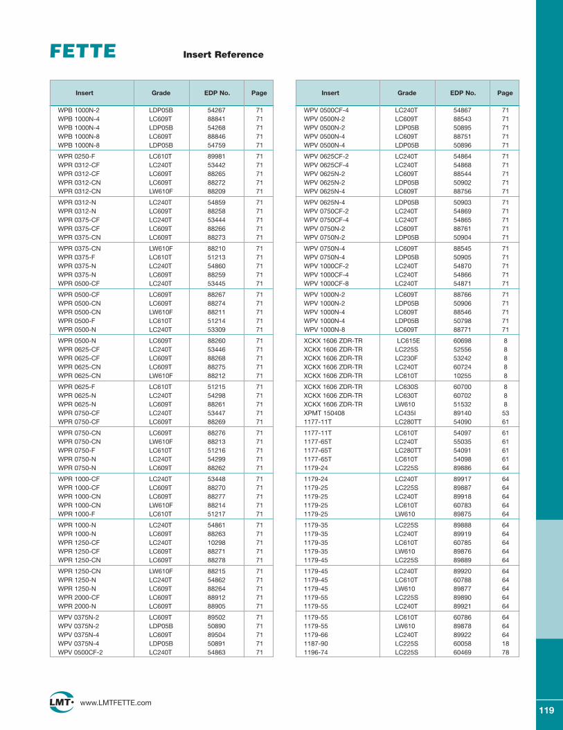
119www.LMTFETTE.com
Insert Reference
Insert Grade EDP No. Page
WPB 1000N-2 LDP05B 54267 71WPB 1000N-4 LC609T 88841 71WPB 1000N-4 LDP05B 54268 71WPB 1000N-8 LC609T 88846 71WPB 1000N-8 LDP05B 54759 71
WPR 0250-F LC610T 89981 71WPR 0312-CF LC240T 53442 71WPR 0312-CF LC609T 88265 71WPR 0312-CN LC609T 88272 71WPR 0312-CN LW610F 88209 71
WPR 0312-N LC240T 54859 71WPR 0312-N LC609T 88258 71WPR 0375-CF LC240T 53444 71WPR 0375-CF LC609T 88266 71WPR 0375-CN LC609T 88273 71
WPR 0375-CN LW610F 88210 71WPR 0375-F LC610T 51213 71WPR 0375-N LC240T 54860 71WPR 0375-N LC609T 88259 71WPR 0500-CF LC240T 53445 71
WPR 0500-CF LC609T 88267 71WPR 0500-CN LC609T 88274 71WPR 0500-CN LW610F 88211 71WPR 0500-F LC610T 51214 71WPR 0500-N LC240T 53309 71
WPR 0500-N LC609T 88260 71WPR 0625-CF LC240T 53446 71WPR 0625-CF LC609T 88268 71WPR 0625-CN LC609T 88275 71WPR 0625-CN LW610F 88212 71
WPR 0625-F LC610T 51215 71WPR 0625-N LC240T 54298 71WPR 0625-N LC609T 88261 71WPR 0750-CF LC240T 53447 71WPR 0750-CF LC609T 88269 71
WPR 0750-CN LC609T 88276 71WPR 0750-CN LW610F 88213 71WPR 0750-F LC610T 51216 71WPR 0750-N LC240T 54299 71WPR 0750-N LC609T 88262 71
WPR 1000-CF LC240T 53448 71WPR 1000-CF LC609T 88270 71WPR 1000-CN LC609T 88277 71WPR 1000-CN LW610F 88214 71WPR 1000-F LC610T 51217 71
WPR 1000-N LC240T 54861 71WPR 1000-N LC609T 88263 71WPR 1250-CF LC240T 10298 71WPR 1250-CF LC609T 88271 71WPR 1250-CN LC609T 88278 71
WPR 1250-CN LW610F 88215 71WPR 1250-N LC240T 54862 71WPR 1250-N LC609T 88264 71WPR 2000-CF LC609T 88912 71WPR 2000-N LC609T 88905 71
WPV 0375N-2 LC609T 89502 71WPV 0375N-2 LDP05B 50890 71WPV 0375N-4 LC609T 89504 71WPV 0375N-4 LDP05B 50891 71WPV 0500CF-2 LC240T 54863 71
Insert Grade EDP No. Page
WPV 0500CF-4 LC240T 54867 71WPV 0500N-2 LC609T 88543 71WPV 0500N-2 LDP05B 50895 71WPV 0500N-4 LC609T 88751 71WPV 0500N-4 LDP05B 50896 71
WPV 0625CF-2 LC240T 54864 71WPV 0625CF-4 LC240T 54868 71WPV 0625N-2 LC609T 88544 71WPV 0625N-2 LDP05B 50902 71WPV 0625N-4 LC609T 88756 71
WPV 0625N-4 LDP05B 50903 71WPV 0750CF-2 LC240T 54869 71WPV 0750CF-4 LC240T 54865 71WPV 0750N-2 LC609T 88761 71WPV 0750N-2 LDP05B 50904 71
WPV 0750N-4 LC609T 88545 71WPV 0750N-4 LDP05B 50905 71WPV 1000CF-2 LC240T 54870 71WPV 1000CF-4 LC240T 54866 71WPV 1000CF-8 LC240T 54871 71
WPV 1000N-2 LC609T 88766 71WPV 1000N-2 LDP05B 50906 71WPV 1000N-4 LC609T 88546 71WPV 1000N-4 LDP05B 50798 71WPV 1000N-8 LC609T 88771 71
XCKX 1606 ZDR-TR LC615E 60698 8XCKX 1606 ZDR-TR LC225S 52556 8XCKX 1606 ZDR-TR LC230F 53242 8XCKX 1606 ZDR-TR LC240T 60724 8XCKX 1606 ZDR-TR LC610T 10255 8
XCKX 1606 ZDR-TR LC630S 60700 8XCKX 1606 ZDR-TR LC630T 60702 8XCKX 1606 ZDR-TR LW610 51532 8XPMT 150408 LC435I 89140 531177-11T LC280TT 54090 61
1177-11T LC610T 54097 611177-65T LC240T 55035 611177-65T LC280TT 54091 611177-65T LC610T 54098 611179-24 LC225S 89886 64
1179-24 LC240T 89917 641179-25 LC225S 89887 641179-25 LC240T 89918 641179-25 LC610T 60783 641179-25 LW610 89875 64
1179-35 LC225S 89888 641179-35 LC240T 89919 641179-35 LC610T 60785 641179-35 LW610 89876 641179-45 LC225S 89889 64
1179-45 LC240T 89920 641179-45 LC610T 60788 641179-45 LW610 89877 641179-55 LC225S 89890 641179-55 LC240T 89921 64
1179-55 LC610T 60786 641179-55 LW610 89878 641179-66 LC240T 89922 641187-90 LC225S 60058 181196-74 LC225S 60469 78

120www.LMTFETTE.com
Notes
Top Related