


Languages
Pages
Legal


MILLING
Milling Teory

Spindle speed, Cutting speed, Cutter diameter
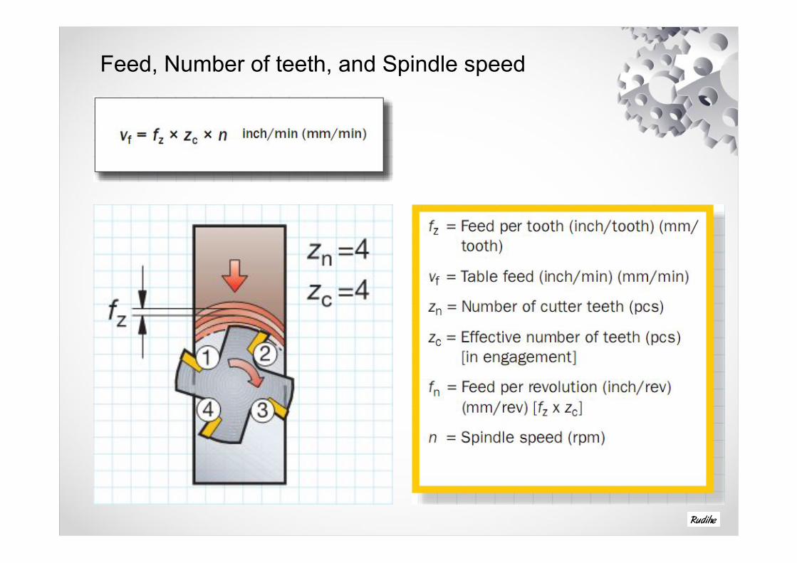
Feed, Number of teeth, and Spindle speed

Daftar Istilah
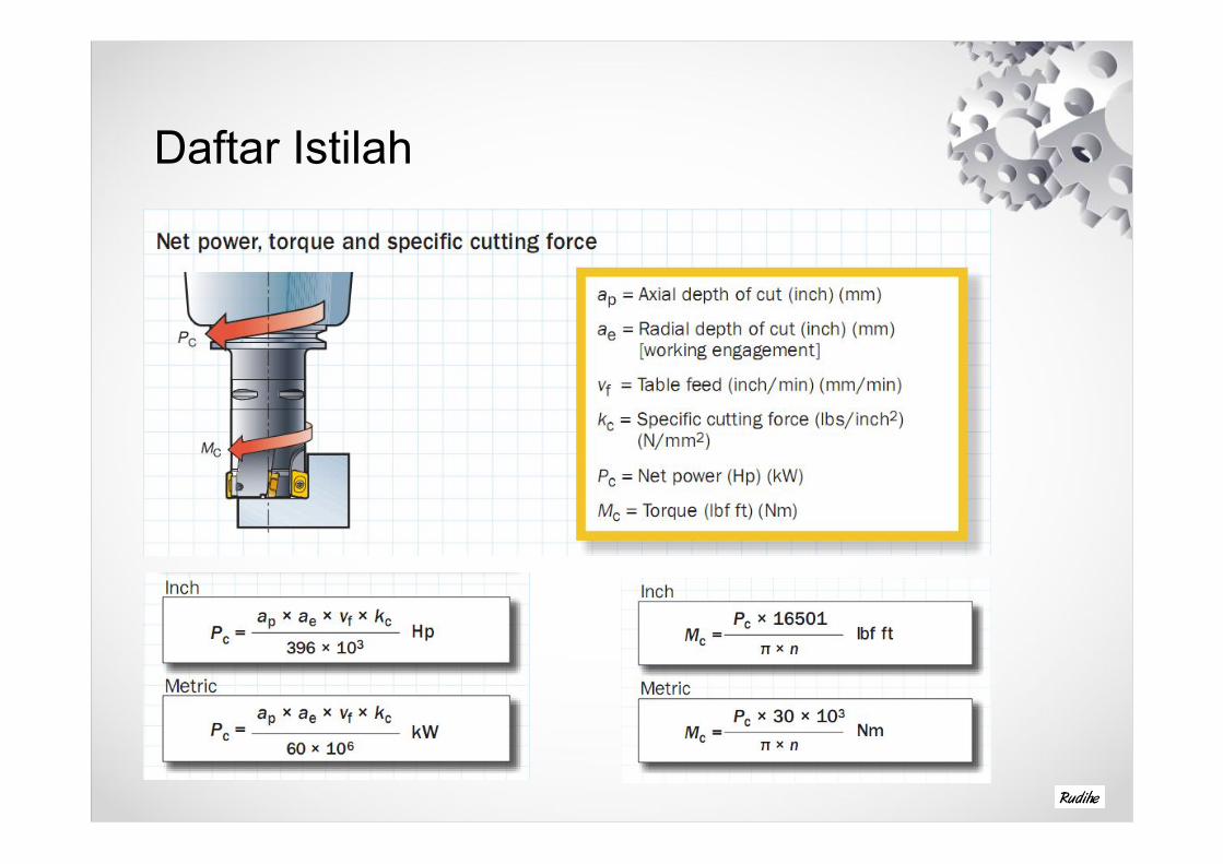
Daftar Istilah

Climb or Conventional millingClimb Milling
Using climb milling ( also referred to as down milling) the burnishing effect is avoided, resulting in less heat and minimal work heat tendency.
• In climb milling, the insert starts its cut with a large chip thickness
Conventional MillingThe feed direction of the workpiece is opposite to that of the cutter rotationat the area of cut.
• In conventional milling ( also referred to as up milling ) the chip thickness starts at zero and ncreases to the end of cut


Cutter diameter and Position

CHIP FORMATION THROUGH CUTTER POSITION
1. Entrance into cut2. Arc of engagement in cut3. Exit from cut

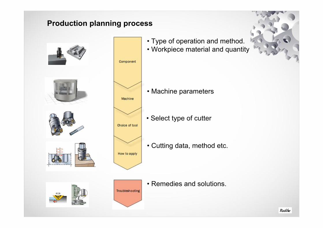
Production planning process
• Type of operation and method.• Workpiece material and quantity
• Machine parameters
• Select type of cutter
• Cutting data, method etc.
• Remedies and solutions.


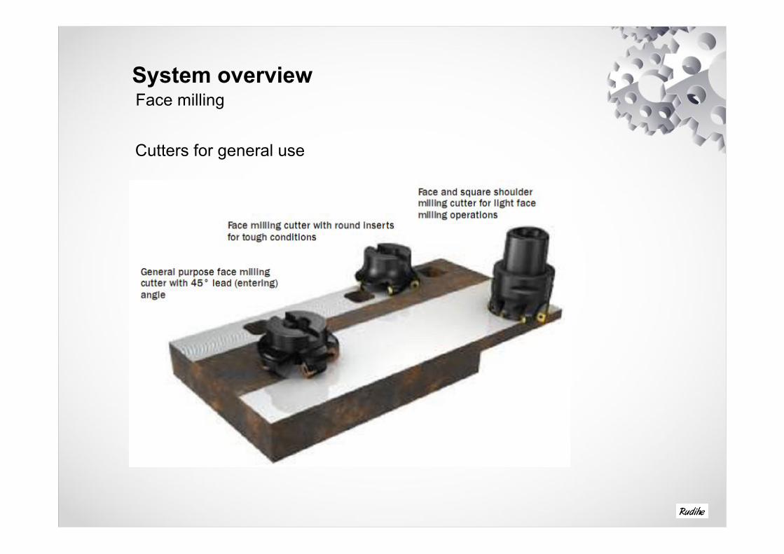
System overviewFace milling
Cutters for general use

Dedicated cutters

Shoulder millingCutters for general use

End mills and long edge cutters

Dedicated cutters
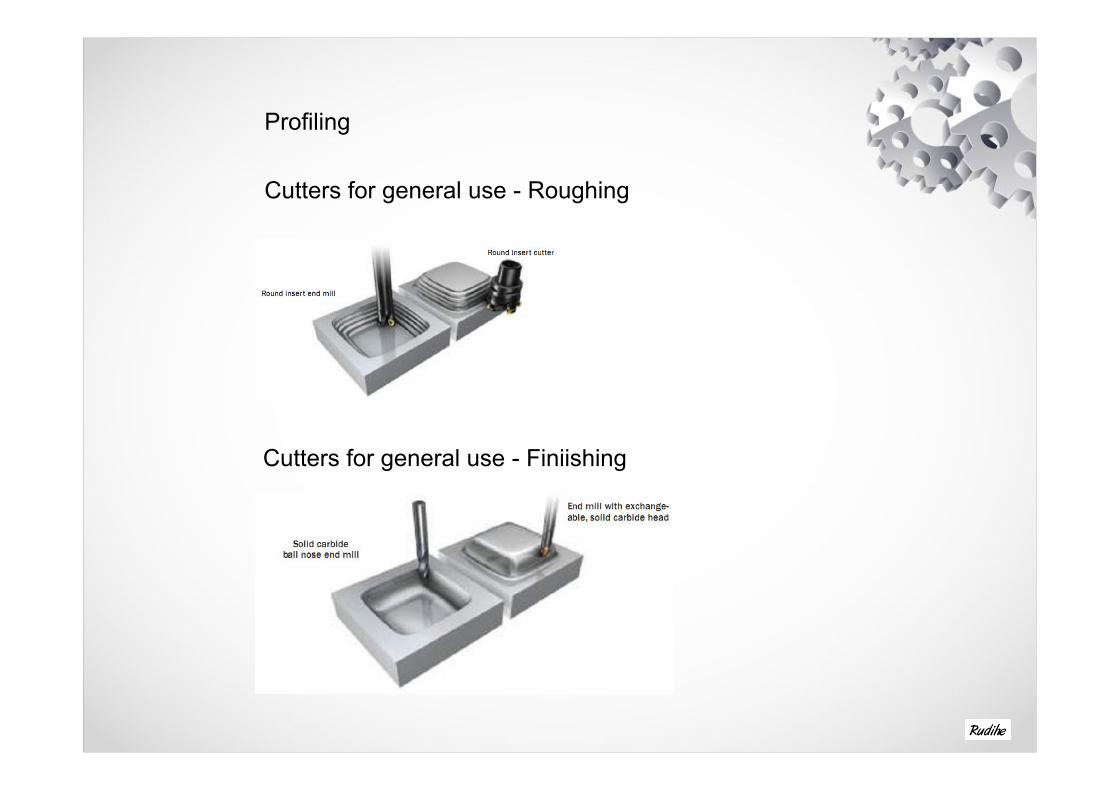
Profiling
Cutters for general use - Roughing
Cutters for general use - Finiishing
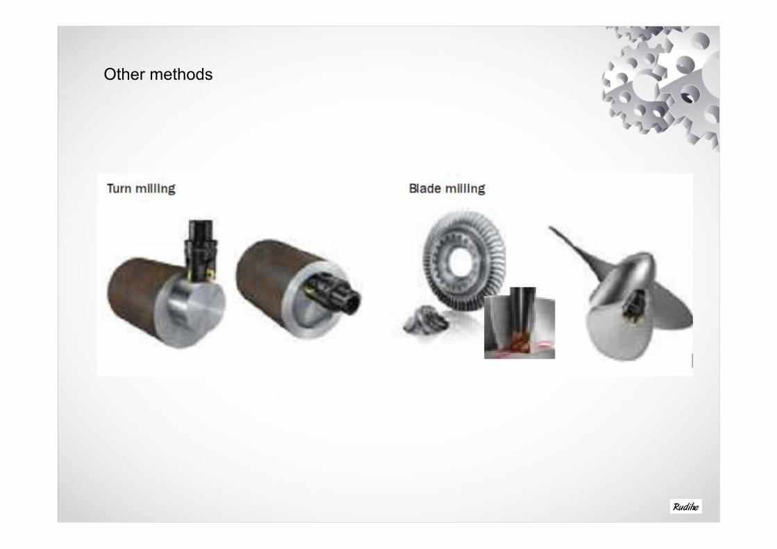
Other methods

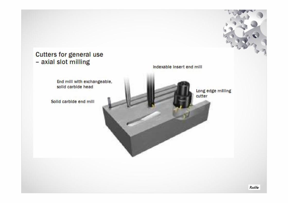
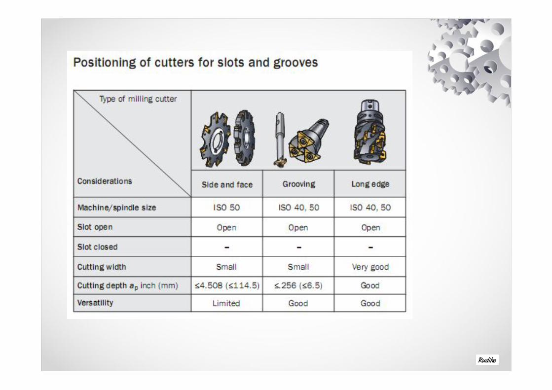
Slot milling


Overview of milling operations
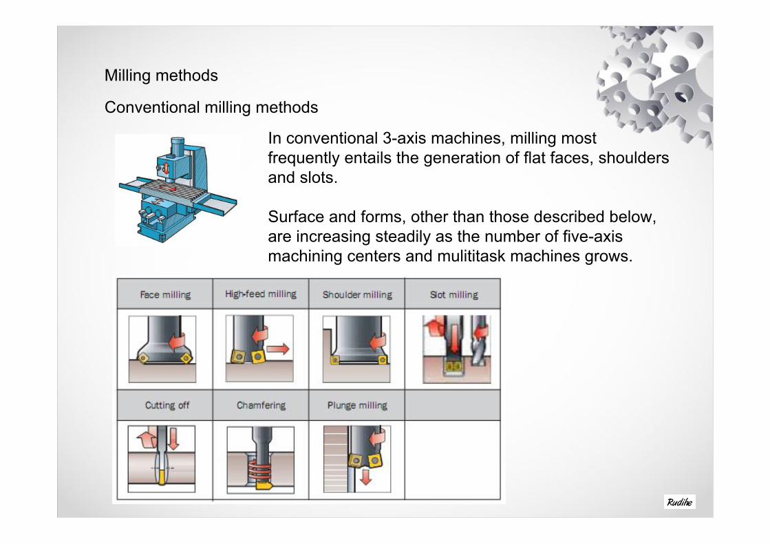
Milling methods
Conventional milling methods
In conventional 3-axis machines, milling most frequently entails the generation of flat faces, shoulders and slots.
Surface and forms, other than those described below, are increasing steadily as the number of five-axis machining centers and mulititask machines grows.

Advance milling methodsModern 4/5-axis machining center or multi-task machine
Today, machines are developing in all directions. Turning centers now have milling capability through driven tools, and machining centers have turning capability via turnmill or mill-turn machines. CAM developments mean that 5-axis machines are increasing.
The results of these trends and the development of methods put new demands and opportunities on the tooling such as :• Increased flexibility• Fewer machines/setups to complete a component• Reduced stability• Longer tool lengths• Lower depth of cuts.


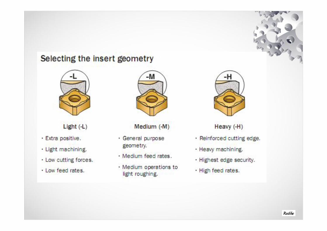
Choice of inserts and how to apply
Modern milling insert for face milling operations.


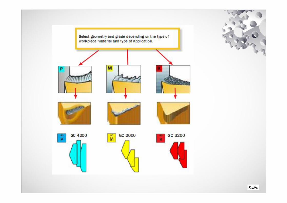
Dedicated grades for ISO P,M, K
Dedicated grades minimize tool wear development
The workpiece material influences the wear during the cutting action in different ways. Therefore dedicated grades have been developed to cope with the basic wear mechanisms, e.g :
• Flank wear, crater wear and plastic deformation in steel• Built-up edge and notch wear in stainless steel• Flank wear and plastic deformation in cast iron.


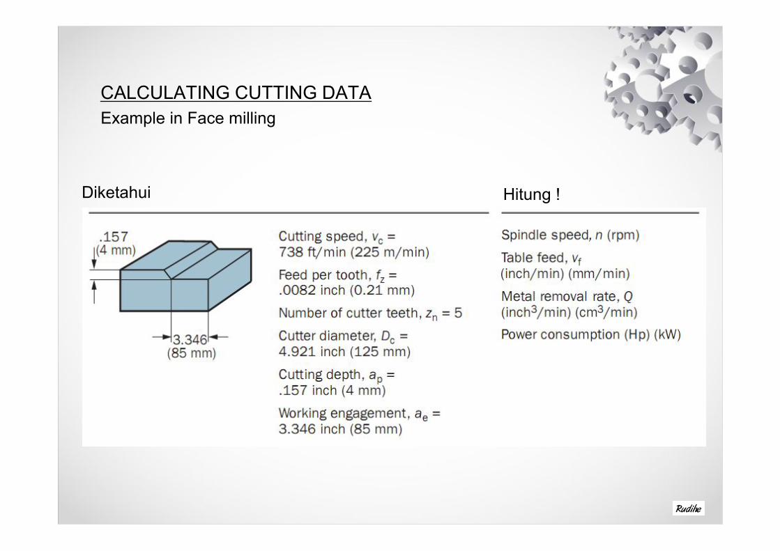
CALCULATING CUTTING DATAExample in Face milling
Diketahui Hitung !

Spindle Speed
Table Feed
Metal Removal Rate

NET POWER CONSUMPTION

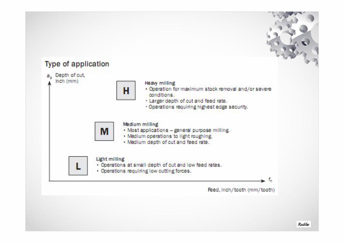
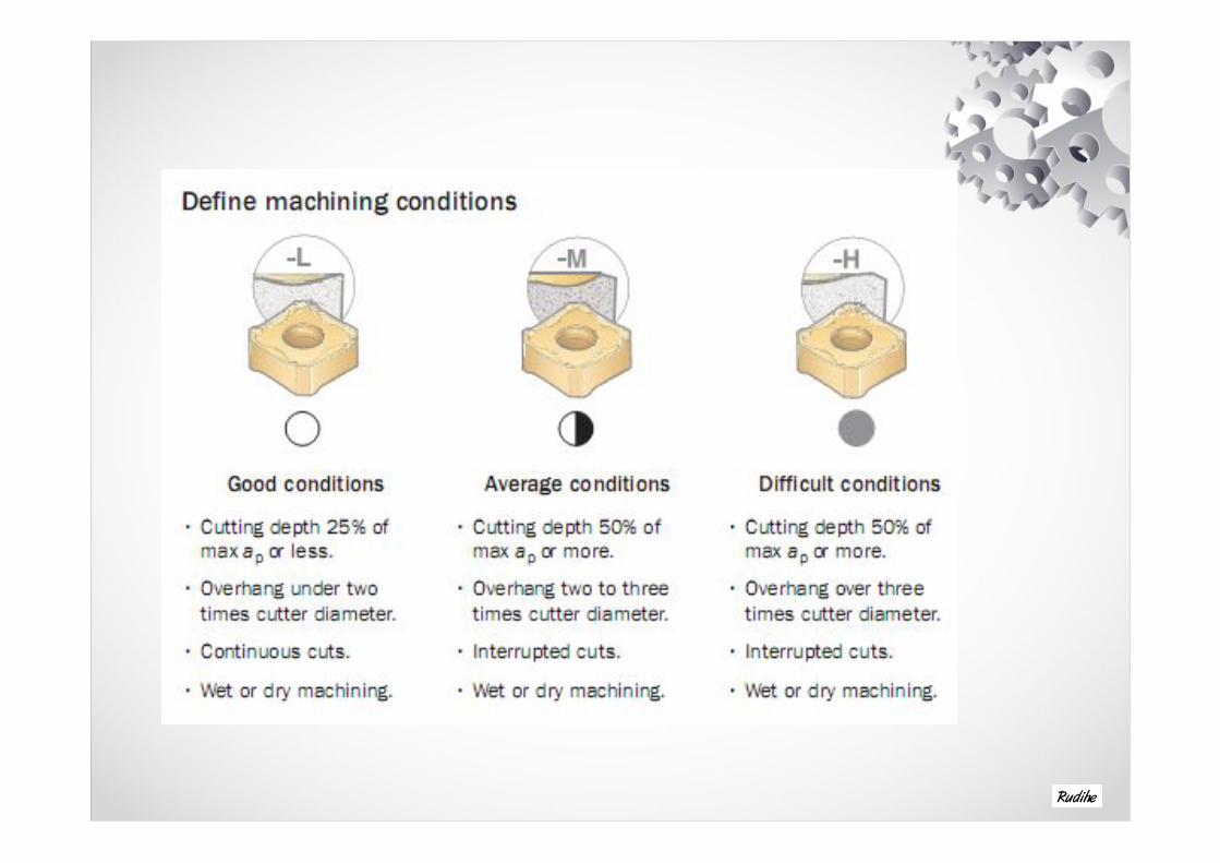
Application hints for milling
Power capacity• Check power capability and machine rigidity, making sure that the machine can handle the cutter diameter required
Overhang• Machine with the shortest possible tool overhang on the spindle
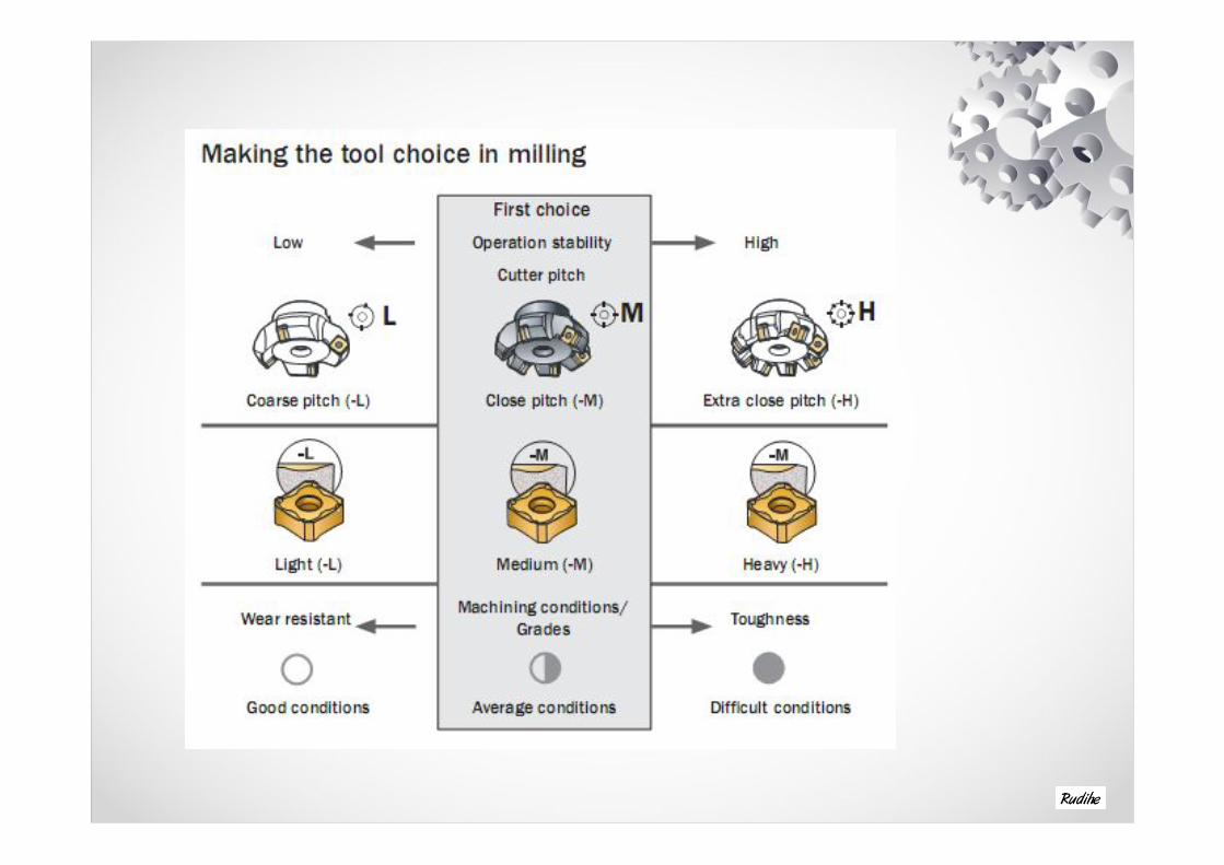
Select correct cutter pitch
• Use the correct cutter pitch for the operation to ensure that there are not too many insert engaged in cut, as this may cause vibration

Cutting engagement
• Ensure there is sufficient insert engagement with narrow workpieces or when milling over voids.
Use correct feed• Ensure that the right feed per insert is used to achieve the right cutting action by use of the recomended maximum chip thickness.
Cutting direction
• Use climb (down) milling whenever possible
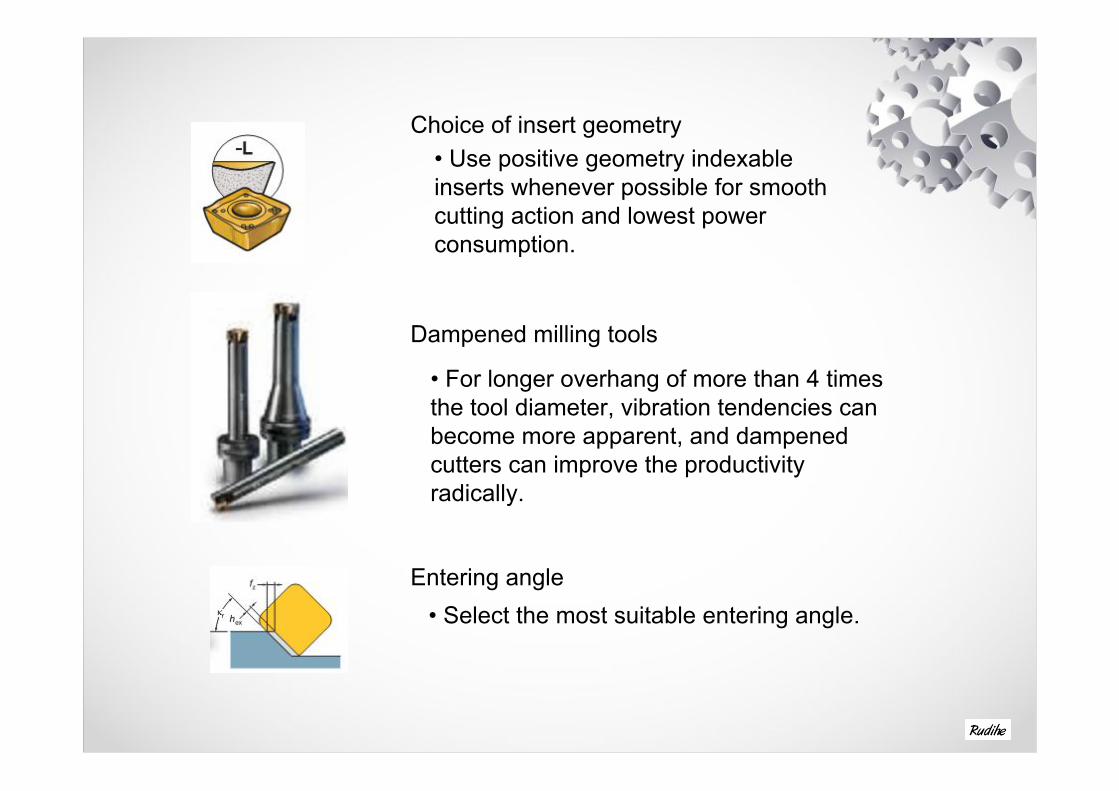
Choice of insert geometry• Use positive geometry indexable inserts whenever possible for smooth cutting action and lowest power consumption.
Dampened milling tools
• For longer overhang of more than 4 times the tool diameter, vibration tendencies can become more apparent, and dampened cutters can improve the productivity radically.
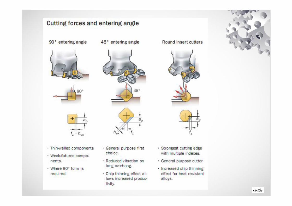
Entering angle• Select the most suitable entering angle.
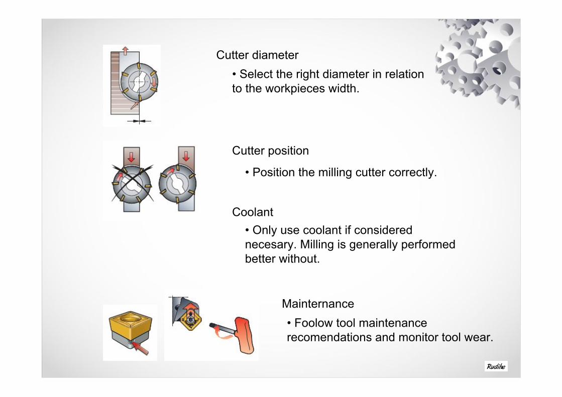
Cutter diameter• Select the right diameter in relation to the workpieces width.
Cutter position
• Position the milling cutter correctly.
Coolant• Only use coolant if considered necesary. Milling is generally performed better without.
Mainternance• Foolow tool maintenance recomendations and monitor tool wear.

Thank You
Top Related