


Languages
Pages
Legal


NOTE: MIL-STD-777 has been redesignated as a Design Criteria Standard. Thecover page has been changed for Administrative reasons. There are no otherchanges to this Document.
MIL-STD-777E(SH) 7 February 1986
SUPERSEDING MIL-STD-777D(SH) 15 April 1977
AMSC N/A FSC 4730 4820DISTRIBUTION STATEMENT A. Approved for public release; distribution isunlimited.
DEPARTMENT OF DEFENSEDESIGN CRITERIA STANDARD
SCHEDULE OF PIPING, VALVES, FITTINGS, ANDASSOCIATED PIPING COMPONENTS FOR NAVAL SURFACE SHIPS
MIL-STD-777E(,SH)7 February 1986
DEPARTMENT OF TNE NAVYNAVAL SEA SYSTEKS COMMAND
Washington, DC 20362-5101
Schedule of Piping, Valves, Fittings and Associated Piping Components forSurface Ships
1. This standard is appr~ved for use by the Naval Sea Systems Command andthe standard is published to establish the requirements for piping system com-ponents on surface ships, in order to preclude the necessity for including apiping schedule in each Navy Ship SpecLficati~n. Tlaisstandard represents andincludes the latest material requirements previously covered in the Ship Speci-fications. It is the intent to refer co this standard in section 505 In theShips Specifications for ●ll new Navy surface ships.
2. Beneficial co=ents (recommendations, additions, deletions) ad anypertinent data which may be of use in improving this document sh?~jd be addressedto: ~nder, Naval Sea Systems Co~, SEA 55Z3, Department of the Navy,Washington, DC 20362-5101 by using the self-addressed Standardization DocumentImprovement Proposal (DD Form 1426) appearing at the end of this document orby letter.
/’”
ii

KIL-STD-777E(SM)7 February 1986
1. SCOPE
1.1 Scope. This standard covers requirements for basic piping system com-ponents on Navy surface IIhtps. It la not the intention herein to include everyconceivable component, valve, or fitting that might be used in the piping systemof a surface ship. The requirements invoked herein are not desirable goals butare minimum acceptable standards.
1.2 This standard is broken down into basic semice categories and groups.The notes contained in each individual category end group and prefaced with thecategory and group designation, apply only to that specific category ●nd group.General requirements are also Zncluded to supplement the spectfic category andgroup notes. General requirements apply to all service categories ●nd groupswhere the content of the requirement is applicable.
1.3 ‘1’hlastandard is bound so that ●ny category .andgroup can be removedand replaced with revised issues of that category and group. It is intendedthat changes,*hen required, will be made to individual categories and groupsonly, rather-than i.sauea complete revision of the standard. Changes will beissued as notices and will be numbered consecutively.
1.4 This standard includes a list of categories and groups with the latestdate of issue for each category and group. When a category and group is revisedthe list of categories and groups will also be revised and will be forwardedfor Insertion in the users copy of the standard.
1.5 This standard shall be maintained with all superseded categories andgroups and list of categories and groups intact to aesure that when users areapplying the standard to requirements which may predate current category andgroup issues, the applicable issues will be available.
2. BEFmLENcED DOCUMENTS
2.1 Government documents. Specifications, standards, drawings, and pub-lications referenced in each category and group of this standard shall form apart of the etandard co the extent specified herein and, unless othewisespecified, shall be the issue in effect on date of invitation for bids orrequest for proposal. Copies of specifications, standarda, drawings, andpublications required by contractor in connection with specific ●cquisitionfunctions should be obtained from the contracting activity or as directed bythe contracting officer.
2.2 Other publications. The following documents form a part of thisstandard to the extent specified herein. Unless othemise epecified, theissues of the documents which are DoD adopted shall be those-listed in theissue of the DoDISS specified in the solicitation. The issues of documents ‘-which have not been adopted shall be those in effect on the date of the citedDoDISS.
ANERICAN NATIONAL STANDARDS INSTITUTE (ANSI)
(Application for copies shouldStandarda Inaticute, 1430 Broadway,
be addresaedNew York, NY
1
to the American National10018.)
MIL-STD-777E(SH)7 February 1986
-RICAN SOCIETY FOR TESTING AND MATERIALS (ASTX)
(bplication for copies should be addressed to the American Society forTesti~-&d Materials, 1916 Race Street, Philadelphia, PA
(Nongovernment ●tandarda sre generally available forlibrariea. They ●re ●lso distributed among nongovernmentusing P@deral agencies.)
3. DEFINITIONS
Not ●pplicable.
4. C’ENEBALSEQUIREKENTS
19103.) -
reference frometandarda bodice and
4.1 For piping directly ●ssociated with a nuclear plant, the requirementsof s8ction 210 of the ●pplicable ship specifications apply in lieu of therequirements ●pccifiad herein. .,
4.2 Gauge piping requirements are specified on Drawing 804-1385850 exceptthat gauge isolation and test valves shall be in accordance with MIL-V-24578 asmodified below:
(a) The material for all parts (except packing or O-ring) may alsobe nickel-copper to ASTN B 164 or B 564.
(b) The lanya~d shall be wire rope coated with flexible, translucentplaatic of co-ercial design with suitable crimped fittings.
(c) The valve design shall provide for a union type connectionbetween the body and the bonnet. The design shall also providefor a positive method for preventing the stem from backing outof the bonnet. This shall be accomplished without the additionof separate pieces or additional operations (such as swaging).The Intention is to have the stem assemble from the bottom ofthe bonnet.
(d) The valve handwheel shall not exceed the dimensions shown on thevalve envelope figure as specified in MIL-V-24578 and shall beround with a non-slip feature or ‘T” shaped and shall attach tothe stem so as to preclude relative motion between the stem andbandwheel. The preferred method of attachment is by flats orspline. If a friction device ie used to attach the handwheelto the stem, a locking method to preclude unintentional loosen-ing of the friction device shall be included. Randwheel materialshall be metal or plastic or a combination of metal and plastic.
(e) The stem back out test is not required.
The use cjfsiphons and flexible connections as a means for providing flexibility18 not mahdatory provided configuration of gauge piping is such that the flexi-bility requirements of Drawing 804-1385850 are met and objectional vibrationsare not transmitted to the gauges on the gauge board. Thermometer wells shallconform to the requirements of Drawing 810-1385917 and MIL-W-24270 usingmaterials selected therefrom compatible with the materials specified for theintended service. Xf discrepancies exist with other specification requirements,clarification should be obtained from Naval Sea Systems Command (NAWEA).
/-’
\
2

MIL-STD-777E(SH)7 February 1986
.
Materials other than those specified are acceptable provided that they areentirely satisfactory in all respects and are approved by the comnand or agencyconcerned. The listing herein does not represent any order of preference.
4.3 Maximum system pressure and temperature ratings of the piping systemsspecified herein are based on the service category and group. If conflict occurswith applicable ship detail specifications or other applicable shipbuilding docu-ments, the operating conditions specified in the latter shall apply. The nor-mal maximum sustained temperature for each of the steels and non-ferrous alloysused in the piping system shall be limited as follows, except that the overallpiping system temperature limitation shall not be exceeded:
Maximum servicePiping materiel temperature ●F
(Tl) (T2)
Carbon steel1 ]/4 percent chrome - 1/2 percent molybdenum steel2-1/4 percent chrome - 1 percent molyMenum steelCorrosion-resisting steel 304, 316347, 321
304L316L
CopperTin-bronzeAluminum-bronzeNaval brass90-10 copper-nickel70-30 copper-nickel70-30 nickel-copper70-30 nickel-copper aluminumNickel-chromium~lybdenum-columbium-alloy
650700700
~/350250300350450650600900
77s100010501000112s600750400550600400600700900
~/ For light drawn temper, 250 degrees Fahrenheit (“F)
4.4 The materials listed in 4.3 may be used up to temperature Tl assumingphysical (not mechanical) properties are equal to those at room temperature.At temperatures above T1 and less then T2, an adequate safety factor based uponthe stress for rupture or the stress corresponding to 1 percent creep (both in100,000 hours), whichever is lower shall be used in the design strees. Thematerials shall not be ueed at temperatures exceeding 72 unless specificallyapproved by NAVSEA, except that for steels specified in 4.3, fluctuations ofnot more than 25*F in excess of T2 are permissible for short duration.
4.5 The piping systems including support structures in machinery andsimilar fire prone spaces shall be designed to remain operational for a speci-fied temperature, time, and heat flux. The design specification shall specifythe time, temperature, and heat flux for which various piping systems are toremain operational for each particular region within the ship.
3
HIL-STD-777E(SH)7 February 1986
4.6 &y valve intended for sea water service not in accordance with aNavy standard drawing shall have nickel copper alloy stems, eeatai,discs, discnuts, hinge pins ●nd side plugs aa applicable. For valvea in sizes 2-1/2inches and above, discs with ● nickel-copper alloy facing of 1/8 inch minimmthickness are acceptable in lieu of solid nickel-copper alloy. Nickel-copper-aluminum or nickel-copper-silicon alloy may be used as an alternative tonickel-copper. Bronze valves for other than sea water eervice may have bronzestems, seats, discs, disc nuts, hinge pins and side plugs, as applicable.
4.7 For valves (except valves on many mechanical standard drawings) fittingsand flanges, contractors dasigns previously approved for comparable inatallationamay be substituted for those specified, subject to justification to and approvalof the c~nd or agency concerned. Extenaiona of the applicability of previouslygranted waivers or approvala for reasons of shipbuilding expediency ●re not valid.
4.8 For”ferrous and special alloy components, eelection of the pressureseries shall be made in ●ccordance with the pressure temperature ratlnga ofANSI B16.5 or B16.34 as applicablein the ●pplicable category.
, unless the eeries Ss specifically designatedButt *:c;.&ingor socket welding fittings shall be
of a schedule or tMckneea compatible with the oervice conditlona.
4.9 Butt welding end valvea, fittings, and flanges shall not be used for.slzessmaller than 1-1/4 inches except that Inert gas consumable insert typebutt welds may be used in eizes down to and including 1/2 inch subject toquallficat~on of procedure by the activity doing the welding. Socket weldingend valves, fittings, and flanges for P-1 piping may only be used in sizes up toand includlng 2 inches. For welding end steel valves, fittings and flangea,the carbon content shall not exceed 0.35 percent.
4.10 The use of long-radiua elbows is desired to minimize flow turbulence.The uae of short-radius elbows is acceptable where apace conditions do notpermit long-radiua elbows.
4.11 Butt welding elbows and return bends shall have 1/2 inch minimumtangenta. For commercial fittings, the 1/2 inch minimum tangents shall beoutside the ANSI radius dimension. Tangents on fitting may be omitted whereconsumable inserts are used or where welding without backing rings is permitted.Where consumable insert welding haa been previously approved for the shipbuilder>y the co~nd or agency concerned, butt welding will be permitted down to andiacluding 1/2 inch.
4.12 Steel valves not covered by military specifications or standard draw-:,again steam and feed systems normally operating at gauge pressures of 150younds per square inch (lb/in2) and above, shall have seat and disc seating:Jurfaceshard faced using material in accordance with type MIL-Co-Cr-A ofMIL-R-17131, or the equivalent. Steel valvea in steam and feed systems below150 lb/ln2 at saturation ternpe=aturesshall have ●ither hard faced operstingseat and disc seating surfaces as specified above or seats and discs hardenedby heat treatment. Special normally open valvee not used for throttling,such as solenoid trips, shall have aesting surfaces suitable for the se=iceapplication.
MIL-STD-777E(SH)7 February 1986
4.13 Where required, straight threaded union connections fitted withO-rings are permitted. Otherwise pipe threaded connections (tapered or straight)between piping, machinery and valves and in piping system joints not permittedexcept aa
4.14except as
4.15each category,
follows:—
(a) Connections to commercial equipment such as washing machines anddrinking water coolers which are not essential to the ship undercombat conditions end where failure would not create a hazard topersonnel, the surrounding area or affect the operation of othervital equipment.
(b) Pipe plugs, of a material compatible with the parent equipmentmaterial in sizes 3/4 inch and below used for applications wheregauge pressures do not exceed 50 lb/in2.
(c) Instrumentation, controls, vents and filling and drain connec-tlone for applications where gauge pressures are 50 lb/ln2 andbelow where fluids handled are neither toxic or dangerous nor .could cause atmospheric contamination and which would notcause. “ the event of fallwre, a major breekbwn of the equip--.. nor create a hazard to t%e surrounding area nor affect theoperation of other vital equipment.
(d) For equipment where taper pipe threads are specified in RR-C-901,KIL+-2/15, liIL-V-17360,NIL-E-15835, KIL-R-15917, HL-H-17902,KIL-H-21291 and PfIL-H-24606.
(e) In unpressurized connections.
Silver brazing fittings shall be of the pre-inserted ring type,follows:
(a) In sizes 1/2 inch nominal pipe size (rips)and below.(b) Fittings without preinserted brazing rings may be used in the
refrigeration system (see category Q-l).(c) hpanded copper sleeves without preinserted brazing rings may
be used in the inner wall of a double-walled gasoline pipingsystem.
(d) Water closet discharge fittings as shown on figures 6 and 7 ofDrawing 810-1385706 may be used without preinserted rings.
(e) Joints for voice tube and pneumatic tube systems.(f) Joints for bellmouth to pipe for tailpipes within tanks.
Threaded fasteners. In addition to the requirements contained In
(a)
(b)
(c)
(d)
the following also appplies:
Piping system fasteners shell be of the UNC series with a class2 or 3 fit.
Threaded fasteners shall be in accordance with HIL-S-1222 withdimensions in accordance with ANSI B18.2.1, washer faced ordoubled chamfered.Studs shall be in accordance with UIL-S-1222, type and style asapplicable.Nuts shall be in accordance with HIL-S-1222, with dimensions inaccordance with MSI B18.2.2, washer faced or double chamfered.
5

MIL-STD-777E(SH)7 February 1986
(e) Nuts located within tanks, in the bilge region or inaccessiblefor examination or routine replacmnt in service shall be ofthe self-locking type as specified in section 075 of the ship’sspecifications.
(f) Bull integrity piping connections are defined as all flanged jointsfrom the hull up to and including the inboard flange of the hullvalve. Included in this category are the bonnet joints of thehull valves and both line flanges ●nd the bonnet joint of thefirst valve (such as blow-out valve) in branch lines connectedto piping between the hull and the hull valve. Connectionsshall be as follows:
(1) Mlted hull integrity piping connections shall be fittedwith nickel-copper-aluminum alloy fasteners in accordancewith MS18116 except that lot identification is not requiredend with self-locking nuts, as specified in (e). Nutsmay be mickel-copper ●lloy QQ+-281 class A or B ornickel-co~per-alwuinum alloy in ●ccordance with QQ-N-286. - ;:
(2) For 8&~ices involving integrity of the hull against the sea,as defined in (f) above, energy abeorbtion shell be pro-vided by making the mounting fasteners essentially constantthroughout their length. ‘fbismay be achieved by threadingover the entire length, reducing the non-threaded shankdiameter to a dimension that fallaibetween the pitchdiameter and the root diameter (usually for cut threads), ortintaining the unthreaded shank diameter the same dimensionae the unthreaded blank (usually for rolled threads). Forresistance to shear forces, mating surfaces of the fastenersholes shall be beveled.
,
.
/—
(g) Nickel-copper alloy bolting in accordance with class Aor B ofQQ-N-281 @hall be used in the following ●pplication:
(1) were subject to sea water spray or submergence.(2) Where not readily accessible for examination or maintenance
In service due to their location and carbon steel, alloysteel, or bronze bolting 1s specified for the rest of thesystem. Some examples are: bilges, below floor plates,tanks, voidm and other hidden areas. Where nickel-copperbolting does not meet the strength requirements of the
joint, nickel-copper-aluminum alloy *N-286 shall be used.
(h) Threaded fasteners in non-ferrous joints where ferrous boltingis specified and located in high condensation areas, such asmachinery spaces, scullery, galley, laundry and sanitary spacesshall be either nickel-copper in accordance with QQ-N-281 orsilicon-bronze in accordance with QQ-C-591.
(i) Wherever non-ferrous flanges mate up to ferrous flanges boltingmaterial shall be either nickel-copper in accordance with QQ-N-281or silicon-bronze in accordance with QQ-C-591.
(j) Carbon and alloy steel fasteners shall be given protective coatingas follows:
\.
6
MXL-STD-777E(SH)7 February 1986
(1) For service temperatures to 1000*F coating in accordancewith ML-C-81751, type I, class 4.
(2) For service temperatures to 650”F and for hfgh humidityareas, coating in accordance with MIL-C-81751, type I,class 4; MIL-C-87115, class 3; or MIL-C-83488, type II,class 3.
(3) For service temperature to 300”F coating in accordancewith F$lL-C-81751,type I, class 4; XI.L-C-87115,class 3;MIL-C-83488, type II, class 3; or ASTM B 633, type II,class 13.
4.16 Flange finishes. The machine surface finish of gasket meting surfaceson flanges in piping systems and connected components shall be in ●ccordance withANSI B46.1 and as follows:
(a) Non-ferrous and ferrous flanges for use with sheet gaskets:
(1) For flanges of a ncminal size of 12 inches or less, a finlehwith a clr” ‘...lay (concentric) of 500’to=1000 or (spiral)125 to 500 roughness height rating (RER) produced bymachining 30 to 80 serrationa of umiform depth per inchof face width.
(2) For flanges over a nominal size of 12 inches, the require-ments shall be the same except th~t 21 to 80 serrationsper inch of face width may be used.
(3) Fir flanges where the flange facemarks run aross the flange face,be a maximum RHR of 500.
(b) Flanges for &ring seals:
(1) A finish of 63 or smoother RHR in(2) A finish of 63 or smoother RHR on
the groove.
cannot be turned and toolthe surface finish shall
(1-ring grooves.the flange face opposite
(c) Ferrous flanges for spiral wound (metallic) gaskets:
(1) A finish with a circular lay (concentric or spiral) of 125to 500 RHR produced by machining not less than 40 aberr-ationsof uniform depth per Inch of face width.
(2) For special installations involvtng radioactive aemtice orhazardous fluids (toxic or explosive) where a finer finish1s required, the requirements shall be same as aboveexcept that the finish shall be 125 RHR maximum.
(3) For flanges where the flange face cannot be turned and toolmarks nm across the flange face, the surface finish shallbe 63 uo 125 8HR.
4.17 Weld joint and backing ring design shall comply with tfIL-STD-22and!4XL-STD-278as appropriate.
4.18 Flat face non-ferrous flanges shall not be mated with raised facesteel flanges. Steel flanges shall be of the flat face or raised face type.
7

MIL-STD-777E(SH)7 February 1986
4.19 Welded branch outlets. Welded branch connections can be effected bythe following techniques:
(a) Extruded.(b) Saddle.(c) Boss.(d) Integrally reinforced branch outlet or integrally reinforced
insert butt welding pipe fitting.
Extruded and eaddle type branch connections shall be designed to meet therequirements of ANSX/ASME B31.1.
,4.20 Unreinforced branch connections (a connection where the branch pipe%s attached directly to the pipe run by welding and joint fabrication does noti~clude the techniques specified in 4.18 (c) and (d)) shell not be used in anysystem where the design gauge pressure is over 150 lb/in2 or the design tempera-ture is over 450”F. The required reinforcement ehall not be obtained via weldbuild-up, and any branch connection fabriqted by the US~lOf welding Only tillbe cmsidered as unreinforced. r
— #b,
4.21 only oil free packing and gaskets shall be used in valves and compo-:~entson nuclear-powered ships in secondary plant systems. Application shallinclude, although not necessarily be limited to, the following:
(a)(b)(c)(d)(e)(f)(g)(h)
Condensate.Feed.Steam drains.Main steam.Auxiliary steam.Air ●jector piping.Distilling (only steam, condensate and distillate portions).Reserve feed.
4.22 Standard bulkhead penetration fittings, are shown on Drawings803-1385866 and 810-1385899.
4.23 Ground joint union bonnets shall not be used in vacuum service ualessthe bonnet design utilizes an O-ring or gasket seal which is totally captured.G?t>,lndjoint unions in accordance with MIL-F-1183, shall not be used for ship-bo’atdpiping applications unless an O-ring gasket and a retainer ring are usedSM a secondary seal.
4.24 Gaskets and threaded fasteners ttotedin this standard are for linejoints only.
4.25 only metallic piping components shall be used in missile blast areas.
4.26 Slip-on flanges shall not be used, except as noted herein.
4.27 The words steam generator, as used in this standard, are applicableto both nuclear and non-nuclear ships installations.

MIL-STD-777E(SH)7 February 1986
4.28 Butterfly valves. Butterfly valve applications shall be in accord-ance with the following:
(a) Butterfly valves are permitted only when specified in the servicecategories within this standard.
(b) Synthetic seated butterfly valves shall not be used im throttlingapplications where the gauge pressure drop exceeds 50 lb/in2 orthe valve opening is less than 20 degrees.
(c) Synthetic seated or metal-to-metal seated butterfly valves shallnot be used in the following ●pplications:(1) As sea water system hull valves.(2) For sea water application in locations where a non-metallic
flexible fitting is installed, the isolation of which isdependent upon closure of a single valve.
(3) Bulkhead damage control cutout valves in win ●nd secondarydrainage, gasoline, and oil systems.
(4) Firemain segregation valves. (That is, those required toset material conditions Yoke ane’
(5) Oil and gasoline tank cutou,
‘Sbra). ....akves, except where the valve
is installed inside a tank or where the valve is outside ofthe tank above the tank top.
4.29 JP-S and fuel pipe ~tarial spedal ●pplicatlome (cargo JP-5 andcargo oil tanks refers to those convertible cargo tanks intended for selectivestowage of JP-5 or fuel) shall be in accordance with the following:
(a) Piping passing through 97P-S,or cargo JP-S and cargo oil tanksshall be 70-30 copper-nickel or shall be completely externallycoated with the same coating material used on the interior ofthe tank.
(b) Piping terminating within a JP-5 or cargo JP-5 and cargo oiltanks shall be 70-30 copper-nickel up to the first stop valve(for sounding tubes, overflows an air escapes up to the firstconnector beyond tank boundary). If the first stop valve iswithin the tank in which the piping terminates, that seccion ofthe piping beyond the stop valve, but still within the tank,shall be 70-30 copper-nickel or shall be completely externallycoated with the same coating material used on the interior ofthe tank.
(c) Piping passing through ships fuel tanks which stows fuel for usein diesel or gas turbine engines shall be 70-30 copper-nickelor shall be completely externally coated with the same coatingmaterial used on the interior of the tank.
(d) Fuel piping passing through clean seawater ballast tanks shallbe 70-30 copper-nickel. There shall be no flanged joints inthe fuel piping within the b-’last tanks.
(e) Valves located within JP-5 or cargo JP-5 and cargo oil tanksshall be of non-ferrous material.
4.30 Naval brass shall not be used in fasteners for stressed applicationsin propulsion plant piping systems, or bolting in flange connections In non-propulsion plant pfping system.
9
KXL-STD-777E(SH)7 February 1986
4.31 Where hose outlets or fill connections are required, a valve inaccordance with the applicable category shall be used. An adaptor for attachinga hose shall be provided on the open end of installed valves. Rose for generalservice applications shall be in accordance with Drawing 810-1385506.
4.32 Fittings dimensionally in accordance with ANSI B16.9 may be substi-tuted for fittings in accordance with Drawing 803-1385880, in copper-nickelpiping systems where butt-weld joint fabrication is used, provided the fittinginside diameter 1s compatible with the pipe or tubing inside diameter.
4.33 Pipe or tube made from Bessemer steel shall not be used in any pipingsystem.
4.34 Where not specified in the tables herein, hose, hose couplings and}ther flexible devices used in piping configuration for noise attenuation orpiping connections to resiliently mounted equipment shall be compatible in allrespects with the other components in the system concerned. Flexible pipingdevices shall be in ●ccordance with the following:
(a) Flexlble hose assemblies: NAVSEA S643O-AE-TED-O1O Volume 1,‘Technical Directive for Piping Devices, Flexible Hose Assem-blies-.
(b) RISIC: NAVSEA S6430-AE-TED-020 Volume 2, ‘Technical Directivefor Piping Devices Flexible, RubberInsert Sound IsolationCouPling (RISIC)”.
4.35 Where commercial valves are used, handwheels 10 inches and less maybe of commercial design and materials except that cast iron shall not be used.Handwheels shall be cast or forged. Aluminum or other non-ferrous material forhandwheels shall not be used in remotely-operated damage control valves.
4.36 Where valve bronze In accordance with MIL-B-16541 or tin bronze inaccordance with QQ-C-390 copper alloy UNS C92200 is specified, tin bronze inwcordance with QQ-C-390 copper alloy tlNSC90300 may be used interchangeably.
4.37 Root connections for instrumentation piping:
(a) Wnere poseible, root connections shall be made into the mide ofpipe or pressure vessel to minimize problems due to air bindingor accumulation of foreign materials in the gauge lines.
(b) Root connections between the outlet and root valve shall be atleast 1/4 inch rips.
(c) Root valves shall be of the same design, material and rating asvalves in the system to which they are connected, exceptstellite-faced seats are not required for root valves In steamand drain lines. However, the hardness for these seats shallbe BliN225 minimum.
(d) The overall size and weight of the root valves shall be kept toa minimum.
f-
10
t’lIL-sTD-777E(sH)7 February 1986
4.38 Flanges shall not be fabricated from bar stock material. Additionallyfittings other than couplings and concentric reducers shall not be fabricatedfrom bar stock material unless a specific document or drawing permits ouch con-struction.
4.39 Hydrostatic testing of forged outlets and fitttngs prior to installa-tion is not required.
4.40 For the radiographic inspection requirements of cast piping systemcomponents refer to ●pplicable ships specifications.
4.41 Where an 8 or 10-tnch ball valve la required, it ●ball meet thedesign, material and test requirements of Drawing 803-5001004, extrapolated forthe larger size, The end connections shall be flanged. Hodiftcation for poweroperation shall be made when required.
4.42 Caskets provided in accordance with MIL-@21032 shall be class B “
\. except that where the gasket is normally exposed to sea water the gr “sb shallbe class C.
4.43 Where sheet gasket material of synthetic rubber in accordance withMIL-G-1149 is specified, cloth insert rubber in accordance with RB-P-lS1 maybe used. However, in using cloth insart rubber gaskets, precautions shall betaken to avoid pickling the joint containing the gasket to remove rust andscale using compounds or solutions containing hydrochloric acid, sulfuric acidor sodium bisulphate.
4.44 The expanding test for piping In accordance with HIL-T-20157 is notrequired since flaring is not permitted for shipboard applications.
4.45 Use of special orfor items where the materialshall be subject to approvalShipyard or F?AVSEA.
4.46 Valve actuators.with DO&V-24657.
4.46.1 For non-nuclearbe designed and installed in
commercial items not covered by this standard andor applicable document has not been desi~atedby the cognizant SupeNisor of Shipbuilding, Naval
Valve electrlc actuators shall be in accordance
ships, remote manual valve actuating systems shellaccordance with the following technical manuals:
(a) S9SO5-AC-MMM-O1O Design Criteria and Installation Requirements;Rigid Rod Valve Remote Control Systems.
(b) S6435-QJ-MMGO1O Design Criteria and Installation Requirements;Remote Mechanical Valve Actuator System - RMVA.
(c) O948-LP-O22-7O1O Valve Remote Control Syster- These systemsshall be limited to a maximum length of eight (8) feet.
4.47 Specific categories and groups contained in this document allow theuse of glass reinforced plastic (GRP) pipe and fittings. However, the use of(XP is limited to the following specific applications:
11
MIL-STD-777E(SH)7 February 1986
(a)
(b)(c)(d)
(e)
(f)
::;
(i)(d)
Deck drain systems, excluding those used for flight decks, hangerdecks, and helicopter platforms, including VERTREP areas.Distilled water systems.Main and secondary drainage systems.Those portions of the chilled water eystem providing non-vitalservices, that is, those services not classified “W, or not amachinery space demand, or not an electronic cooling watersystem-.
Those portions of the low pressure compressed air system pro-viding non-vital services, that is, those services whose con-tinued operation is not essential for maintaining ship con-trol, propulsion, comnicatlons, seaworthiness, combat capa-bility or survivability.Oily water and waste water drain collecting ayatem.Plumbing vents.Potable water.Seawater flushing eystams.Those por$~s of seawater coollng systems providing non-vitalservices, thet,is, those services whose continued operation=is -not ●ssential for maintaining ship control, propulsion, com-municet&on#, seaworthiness, combat capability or ●urvivabillty.
4.48 Except for GRF or wood hull ships, the total amount of CRP in aspace shall not exceed 25 pounds per 1000 cubic foot of volume for empty PIPSsituations, and 50 pounds per 1000 cubic foot of volume for flowing or stagnantpipe situations.
5. SERVICE CATEGORIES AND CROUPS
5.1 Semite categories and group6 ehall be as specified hereinafter. When-my category and group is modif~ed, this record will be corrected and reissuedto indicate the latest date of issue of that category ●nd group.
5.2 For each service category and group, the reference to maximum systemfor pressure and temperature is not meant to infer that only systems with theseconditions are applicable to the category and group; only that the componentsand materials identified ●re suitable up to these maximum conditions, unlesswotes within ● category ar.dgroup identify other limitations. The contractor.,.:installing activity shall be responelble for matching system requirements asclosely as possible with the ●pplicable category and group.
?ategory and grou~.,---
A-1A-2A-3
A-4A-5A-6A-7
se-ice
Steam and steam drains, 1500 lb/Lu2, 1000”FSteam and steam drains, 1500 lb/in2, 775°FPropulsion plant saturated steam ●nd steamdrains, 600 to 1500 lb/in2, 775*FSteam and steam drains, 600 lb/in2, 875°FSteam and steam drains, 600 lb/in2, 775°FSteam and steam drains, 150 lb/in2, 775*FSteam, 100 lb/in2, 875°F
Date
February 7, 1986February 7, 1986February 7, 1986
February 7, 1986February 7, 1986February 7, 1986February 7, 1986
/’
12
!41L-STD-777E(m)7 February 1986
Category and group Service Date
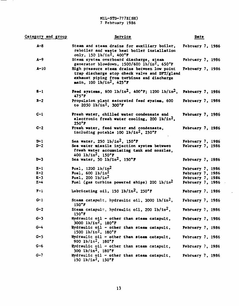
A-8
A-9
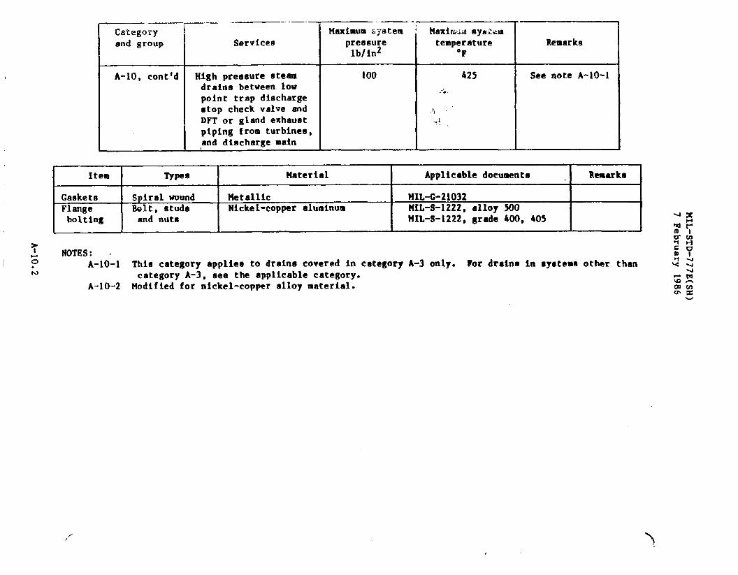
A-10
Steam and steam drains for auxiliary boiler, February 7, 1986reboiler and waste heat boiler installationonly, 150 lb/in2, 400°FSteam system overboard discharge, 8team February 7, 1986generator blowdown, 1500/600 lb/ixt2,650”FHigh pressure steam drains between low point February 7, 1986trap discharge stop check valve and DXT/glandexhaust piping from turbines and dischargemain, 100 lb/in2, 425*F
Feed systems, 600 lb/in2, 400”F; 1200 lb/in2,475°FPropulsion plant saturated feed system, 600to 2050 lb/in2, 300°F
Resh water, chtllad water condensate andelectronic fresh water coolimg, 200 lb/in2,250°F
Fresh water, feed water and condensate,including potable 100 lb/in2, 250”F
Sea water, 250 lb/in2, 150°FSea water missile injection system betweenfresh water accumulating tank and nozzles,400 lb/in2, 150°FSea water, 50 lb/ln2, 150”F
Fuel, 1200 lb/in2Fuel, 600 lb/in2Fuel, 200 lb/in2Fuel (gas turbine powered ships) 200 lb/in2
Lubricating oil, 150 lb/in2, 250”F
Steam catapult, hydraulic oil, 3000 lb/in2,150*F
Steam catapulr, hydraulic oil, 200 lb/in2,
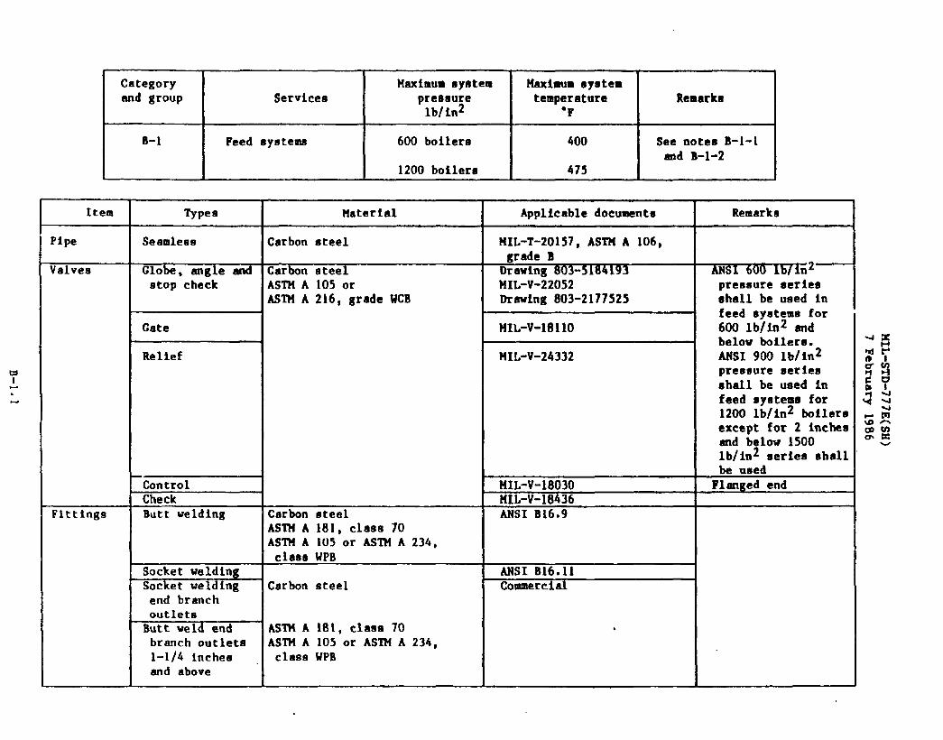
B-1 February 7,
February 7,
1986
1986B-2
c-1 February 7, 1986
c-2 Fabruary 7, 1986
February 7,February 7,
19861986
D-3
E-1E-2E-3E-4
F-l
*1
G-2
G-3
G-4
G-5
G-6
G-7
February 7, 1986
February 7,February 7,February 7,February 7,
1986198619861986
1986 .February 7,
February 7, 1986
February 7, 1986150°F -
Hydraulic oil3000 lb/in2,
Eydraulic oil1500 lb/in2,
Rydraulic oil
- other than steam catapult,180”F- other than steam catapult,180”F- other than steam catapult.
February 7, 1986
February 7, 1986
February 7, 1986900 lb/in2, 180”FHydraulic oil - other than steam catapult,300 lb/in2, 180”FHydraulic oil - other than steam catapult,150 lb/in2, 150”F
February 7, 1986
February 7, 1986
MIL-STD-777E(SH)7 February 1986
Category and group Service
E-1E-2
1-1
J-1J-2J-3J-4J-5
J-6
J-7..-,*
‘7SLLJ-8J-9
K-1
K-2
K-3K-4K-5K-6K-7
L-1
M-1
N-1
N-2
0-1
P-1
Q-1
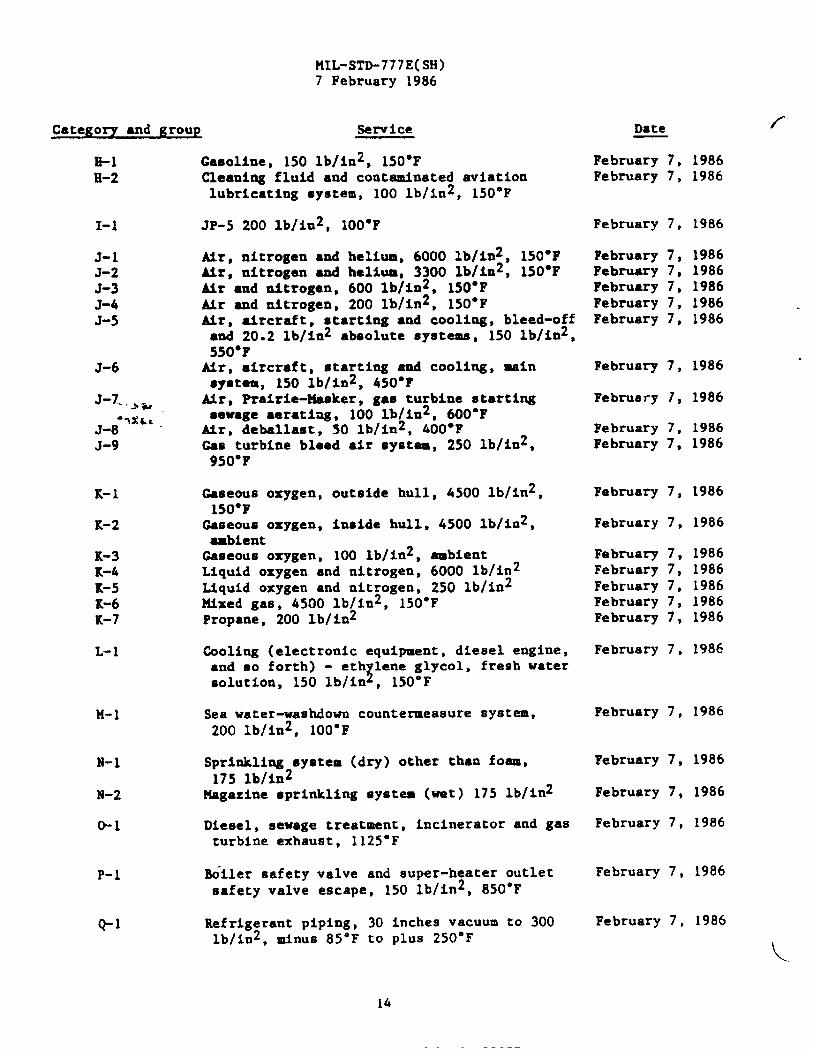
Casoliue, 150 lb/in2, 150”FCleaning fluid and contaminated aviationlubricating system, 100 lb/in2, 150°F
JP-5 200 lb/in2, 100”F
Nr, nitrogen ●nd helium, 6000 lb/im2, 150”FMr, nitrogen and helium, 3300 lb/in2, 150°FMr and nitrogen, 600 lb/in2, 150°FAlr and nitrogen, 200 lb/in2, 150”FMr, aircraft, starting and cooling, bleed-off
●nd 20.2 lb/in2 absolute systems, 150 lb/in2,550”Ftir, aircraft, mtarting and cooling, mafnsystem, 150 lb/in2, 450”FMr. Prairie-Masker, gas turbine startingsewage ●erating, 100 lb/in2, 600”FAir, debellaat, 50 lb/in2, 400°FCam turbine bleed ●ir system, 250 lb/ln2,950”F
Gaseous oxygen, outside hull, 4500 lb/in2,L50”F
Gaseous oxygen, inside hull, 4500 lb/in2,ambientGaseous oxygen, 100 lb/in2, ambientLiquid oxygen and nitrogen, 6000 lb/in2Liquid oxygen and nitrogen, 250 lb/in2Mixed gas, 4500 lb/in2, 150”FPropane, 200 lb/in2
Cooling (electronic equipment, diesel engine,●nd so forth) - eth lene glycol, fresh water
zsolution, 150 lb/in , 150°F
Sea water-wasMown countermeasure system,200 lb/in2, 100”F
Sprinkling system (dry) other than foam,175 lb/in2
Magazine sprinkling system (wet) 175 lb/in2
Diesel, sewage treatment, incinerator and gasturbine exhaust, 1125°F
M“iler safety valve and super-heater outletsafety valve escape, 150 lb/in2, 850”F
Refrigerant piping,lb/in2, minus 85°F
30 inches vacuum to 300to plUS 250”F
16
Date f
February 7, 1986February 7, 1986
February 7, 1986
February 7, 1986February 7, 1986February 7, 1986February 7, 1986February 7, 1986
February 7, 1986
February 1, 1986
February 7, 1986February 7, 1986
February 7, 1986
February 7, 1986
Febmary 7, 1986February 7, 1986February 7, 1986February 7, 1986February 7, 1986
February 7, 1986
February 7, 1986
February 7, 1986
February 7, 1986
February 7, 1986
February 7, 1986
February 7, 1986

BIIL-STD-777E(SH)7 February 1986
Category and group SewIce Date
R-1
B-2R-3
R-4
s-1
T-1
T-2,,,.-
T-3
u-1
v-1
u-1
Y-1
Y-2
Y-3
Y-4
Waste water, oily waste bilge, stripping, February 7, 1986weather deck and cont~nated deck drains50 lb/in2, 150”FChemical drains, 30 lb/in2, 150*F February 7, 1986Drains and vents, deck drains and plumbing, February 7, 198650 lb/in2, 150°Fsewage collection, holding and transfer (CRT), February 7, 198650 lb/in2, 150”F
Aqueous film-forming foam (AFFF) concentrateend APFF/SU solution, 250 lb/im2
Fixed C02, cofferdao Inerting eyutems, 1900lb/in2WON 1301 fire extinguishing systems distri-bution piping and discharge piping, 2800.,..lb/in2, 200”F
EALON 1301 fire extinguishing systems actua-tion piping, 2800 lb/ia2, 200”F
Stripping, fuel, 150 lb/la2
Voice tubes
Pneumatic tubes
Overflows, sounding tubes, vents ●nd airescapes for JP-5 tanksOverflows, sounding tubes, vents and airescapes for fuel tanks (except JP-5)Overflows sounding tubes, vents, and air
February 7,
Febnmry 7,
February 7,
February 7,
February 7,
February 7,
February 7,
February 7,
February 7,
February 7,
1986
1986
1986
1986
1986
1986
1986
1986
1986
1986escapes for other than fuel tanks (freshwater (except potable) clean ballast, voids,etc.)Vents, reduction gear, S lb/in2 ambient February 7, 1986
Preparing ●ctivity:Navy - SE(Reject 4730-N644)
15

&●
.
Category Maximum eystem Maximumsystemand group Services pressure temperature Remarke
lb/in2 “F
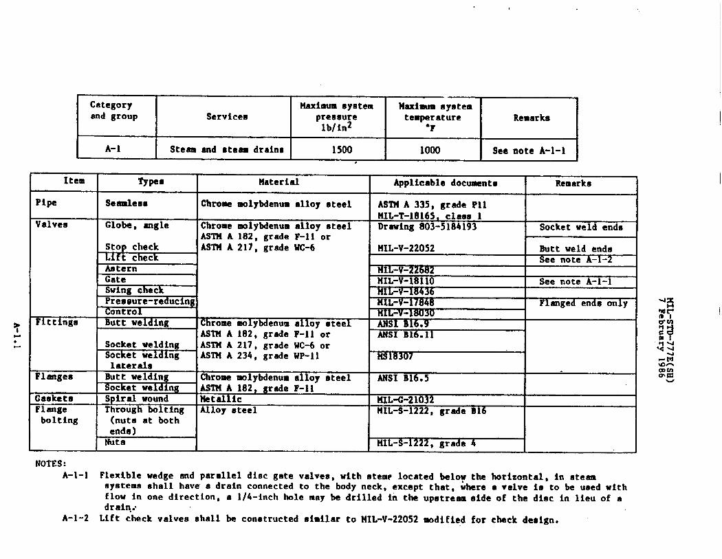
A-1 I Steam and ●te- dralno 1500I
1000I
9ee note A-1-l#
NOTES:A-l-1 Flexiblewedge and paralleldisc gate valvea,with stem? locatedbelow the horizontal,in eteem
systems shall have a drain connectedto the body neck, except that, where ● valve 10 to be used withflow in one direction,a l/4-inchhole may be drilled in the upotre~ eide of the disc in lieu of adrain:
A-l-2 Lift check valves shall be constructedsimilar to HIL-V-22052modified for check design.
Category Maximum system Naximumsystemand group Services pressure temperature Remarks
lb/in2 “F
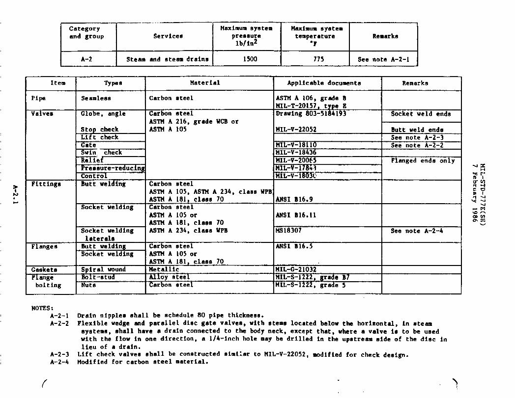
A-2 Steam and steamdrains 1Soo 775 See note A-2-I
Item I Types I Material
NOTES:A-2-1A-2-2
A-2-3A-2-4
Pipe I Seamle8a ICarbon steelValves Globe. angle Carbon steel
ASTM A 216,grade WCB orASTN A 105
Premsure-reducingControl
Fitting8 Butt welding Carbon steelASTN A 105,ASTM A 234, claaaWPE
I IAS’l?fA 181,class 70Socket welding ICarbon steel
I - ]ASTMA1050r
L=imi-1 ASTMA 181,class 70ASTN A 234, class WPB
laterahFlanges Butt welding Carbon steel
Socket welding ASTN A 105orAS’ll!A 181,claas 70
Gaekete Spiral wound HetallicFlange Boit-stud Alloy steelbolting Nuts Carbon steel
Applicabledocuments I Remarka
ASTN A 106,grade BNIL-T-20157,type 1?Orawing803-5184193 Socketweld ends
141L-V-22052 Butt weld endsSee note A-2-3
HIL-V-18110 See note A-2-2tIIIL-V-18436MIL-V-20065 Flangedends onlyk!IL-v-17e&3PIIL-V-i803U
ANSI B16.9 I
ANSI B16.11
NS18307 See note A-2-4
ANSI B16.5
ML-G-21032MIL-S-1222,grade B7)fIL-S-1222, grade 5
Orain nipples shall be schedule80 pipe thickneaa.Flexiblewedge and paralleldisc gate valvee,with otems locatedbelow the horizontal,in oteamsystems, shall have a drain connectedto the body neck, except that,where a valve 10 to be usedwith the flow in one dtrection,a l/4-inchhole ❑ay be drilled in the upstreamaide of the diet inlieu of a drain.Lift check valves shall be constructedsimilarto MIL-V-22052,modifiedfor check deeign.Modified for carbon steel material.
( >

Categ ryand group
A-3
Services
Propulsionplantsaturatedsteamand steam draina
Maximum syetempressurelb/in2
600 to 1500
Maximum systemtemperature
“?
775
Remarke
See note A-3-1

.—.Categoryand group
A-3, dent’d
..— .
Services
Propulsionplantmaturatedsteamand steam drains
Maximum systempressurelb/in2
600 to 1500
—14aximumSyeltemdtemperature
‘F
77s
IRemarks
I
I
Item Types Material Applicabledocumente Remarks
Fittings Flanged Carbon steelASTM A216, grade WCB MSI B16.3
Butt welding Carbon steel MSI B16.9AS’illA 105, ASTM A 181,clam 70ASTM A 234, claso WPB ;S
Socket welding Carbon steel ~. ANSI B16.11AsTWA 105 or ASTMA 181;clam 70
Socket welding ASTH A 234, class WPB HS18307 See note A-3-3lateral
Flangea Butt welding Carbon steel ANSI B16.5ASTH A 105 or ASl?lA 234,class WPB
Socket welding AS’114A 181, class 70Gaskets Spirai wound Metallic HIL421032Flange Bolt-stud Alloy steel B7bolting Uut
s gr~eCarbon oteel !41L-S-1222, grade 5
NOTES:A-3-1 This category excludeshigh pressureatesm drain ●ain betweeneach low point trap dischargestop-check
valve and the deaeratorfeed tmk (DFT),which shall be in accordancewith categoryA-10 herein.A-3-2 Flexiblewedge and paralleldiet gate valves, in steam systems,@hall have a drain connectedto the
body neck, except that,where a valve 18 to be ueed with the flow in one direction,a l/4-inchholemay be drilled in the upstream side of the disc in lieu of a d:ain.
A-3-3 Uodified for carbon steel material.A-3-4 Valve design proposalin accordancewith ?41L-V-24619shall be submittedto NAVSEA for review end
approval.

MIL-STD-777E(SH)7 February 1986
nm:4J
—
—
—
d
A-6.1

—.—. .. . . .-— — .—
Category :end group
I
Service8
A-5 I Steam end steam drains
hximum systempreenurelb/5n2
600
1
14aximm syateu Itemptwature Remarks
‘F,
715I See note A-5-1
Item Typee llaterial Applicabledocumente Remarks
Pipe Seamleae Carbon steel I!IL-T-20157ASTHA 106, grade B
Valvet3 c1Obe angle end Carbon steel Drawing803-21~ Socket weld endsstop check ASTttA2i6, grade UCB HIL-V-22052 Butt weld ends
ASTN A 105Aetern 141L-V-22682Gate I4IL-V-1811O See note A-5-28wing check NIL-v-18436Pressure- F1anged ends onlyreducingRelief HIL-v-20065Control HIL-V-18030
Fittings Butt welding Carbon steel ANSI B16.9ASl?iA 234, claseUPSAS’IHA 105, ASTM A 181, class 70
Flanged Carbon steel ANSI B16.5AS’1’tIlA216,grade WCB
Socket welding Catbon steel ANSI B16011ASTM A 105 or
Socket welding ASTU A 181, class 70 H818307 See note A-5-3lateral ASTN A 234, claeaWPB
Flanges Butt welding Carbon steel ANSI B16.54
ASIM A 105 or ASTN A 234,class WPB
Socket welding A8’l?fA 181, class 70 1’
Gaskete Spiral wound Metallic KIL-G-21032.F1ange Bolt-stud Alloy steel NIL-S-1222,grade B7bolting Nut Carbon eteel MIL-S-1 20 grade 5
NOTES:A-5-1 Drain nipples shall be schedule 80 pipe thickness.A-5-2 Flexible wedge md parallel disc gate valvee, with stems located below the horizontal,in steam aystema
shall have a drain connected to thein one direction,l/4-inchhole may
A-5-3 Modified for carbon steel material.,/’
body neck,be drilled
exceptin the
that,where a valve is to be used withupstreamaide of the diet in lieu of a
the flowdrain.
Category ‘and group
ISetvfce8
vandeteamdraineItem
Pipe
Valves
Fittings
Flanges
Gaskets
Flangebolting
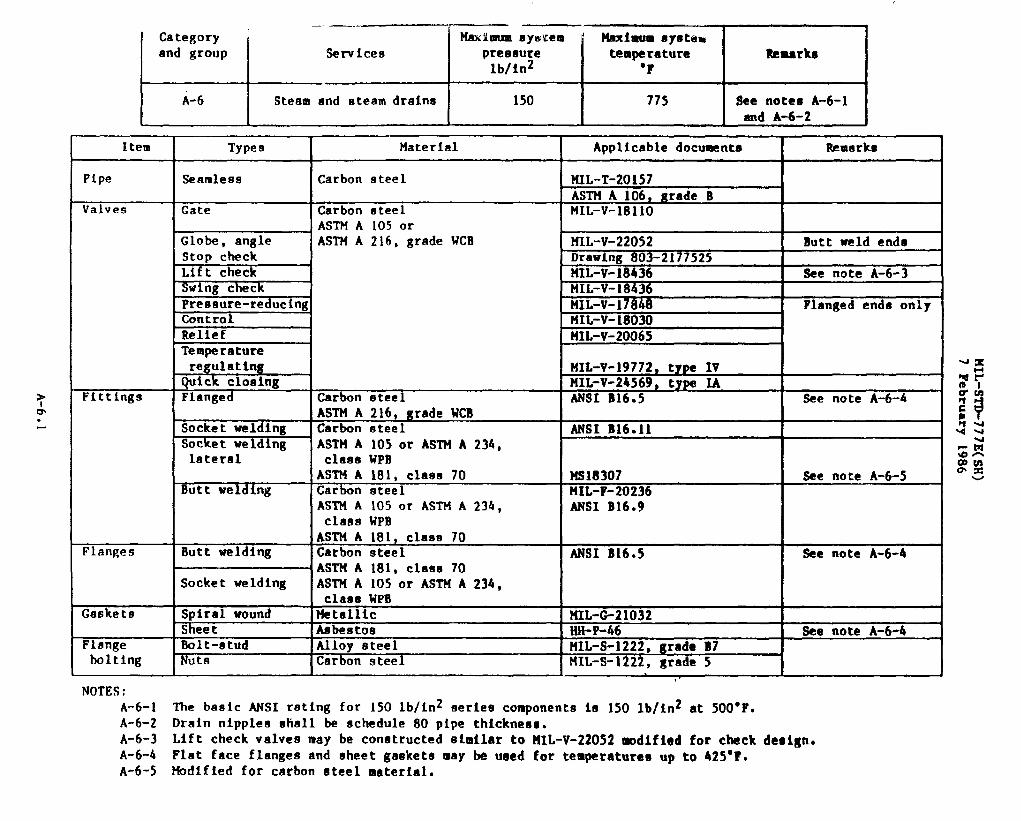
NOTES:
Types
Seamless
Gate
Globe, angleStop checkLift check?h?ingcheck-–––pressure-reducingControlReliefTemperatureregulatingQuick closingFlanged
Socket weldingSocketweldinglateral
Butt welding
Butt welding
Socket welding
!%iralwoundSheetBolt-studRuts
llax~mmay~tem Uaxhum Sptampressure temperaturelb/in2 “F
150 775
Remrka
Bee notes A-6-1and A-6-2
Material I Applicabledocuments
Carbon steel MIL-T-20157ASTMA 106, grade B
Carbon oteel MIL-V-1811OASTM A 105orASTM A 216,grade WCB MIL-v-22052
Drawing803-2177525MIL-V-18436MIL-V-18636MIL-V-1~848XIL-V-18030MIL-v-20065
MIL-V-19772,type IVMIL-V-24569,type IA
Carbonsteel ANSI B16.5ASTM A 216,grade WCBCarbon steel ANSI B16.11ASTM A 105or ASTM A 234,claesWPBASTM A 181,claas 70 IMS18307Carbon steel 1HIL-F-20236ASTM A 105or ASTM A 234,
IANSI B16.9
class WPBASTM A 181,class 70Carbon steel ANSI B16.5ASTM A 181,claaa 70ASTM A 105 or ASTM A 234,claaa WPBMetallic ?KL-G-21032Aabeatoa WI-P-46.—- - .-Alloy steel If41L-S-1222,grade B7Carbon steel IHIL-S-1222,grade 5
A-6-1 The basic ANSI rating for 150 lb/in2seriescomponentsis 150 lb/in2at 500”F.A-6-2 Drain nipplesshall be schedule80 pipe thickneae.
Remarks
Butt weld enda
See note A-6-3
Flangedende only
See note A-6-4
See note A-6-5
See note A-6-b
See note A-6-4
A-6-3 Lift check valves may be constructedsimilarto RtIL-V-22052mdified for check deeign.A-6-b Flat face flangesand sheet gasketsmay be used for temperaturesup to 425’?.A-6-5 Modified for carbonsteel material.
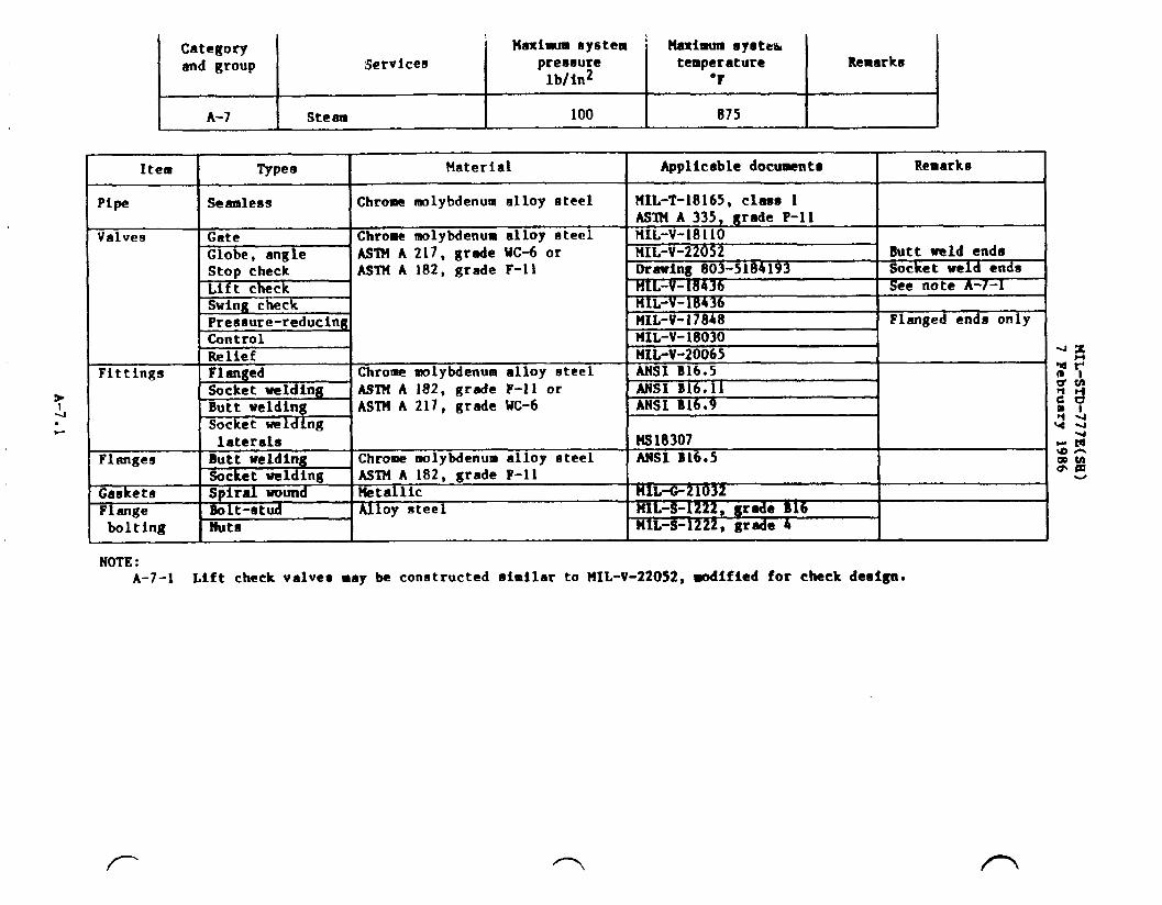
Category Maximumsystem i naximumllyeteaand group Services preseure temperature Remarks
lblin2 “F
A-7 Steam 100 075
Item ‘T Types Material I Applicabledocu~nta I Remarks
Pipe ISeamless IChromemolybdenumalloy steel
&+’s-l ASl?fA 182;grade F-n
Swing checkPressure-reduclnu
?41L-T-18165,class 1AsmA335p grade P-11
Valves Gate Chromemolybdenumalloy steel HIL-V-1811OGlobe. angle AST?4A 217. grade UC-6 or HIL-V-22052 Butt weld ends
Drawing803-5184193 Socketweld endsSee note A-7-1
HIL-V-18436HIL-V-17848 Flangedends onlyMIL-V-18030
!Relief z41L-V-20065Fittings Flanged Chromemolybdenumalloy steel ANSI B16.5
Socketwelding AS1’?lA 182,grade F-n or ANSI B16.11Butt welding ASTM A 217, grade WC-6 ANSI B16.9
A
Socket-Iding
IControl I
laterala MS18307Flanges Butt welding Chromemolybdenumalloy steel ANSI B16.5
Socketwelding AST?lA 182,grade F-nGasketa Spiralwound Hetallic HIL+21032Flange Bolt-stud Alloy steel 141L-S-1222,grade B16bolting Nuts ?lIL-S-~ , 8r~e 4
u
NOTE:A-7-I Lift checkvalves ●ay be constructedeimilarto MIL-V-22052,wd$fted for check design.

Categoryand group Servicee
A-8 Steam and steam drainsfor auxiliaryboiler,rebollerand wasteheat boiler installa-tion only
?faximua ay8tempreasutelb/in2
150
Hanimum systemtemperature
‘F
358(Sat. temp.)
I&marks
See note A-8-1and A-8-3
NOTES:A-8-1 For other boiler installation, use other applicablecategory.A-8-2 100 lb/in2 maximum for angle and crose configurationonly.A-8-3 Use category A-6 for superheatedsteam application.
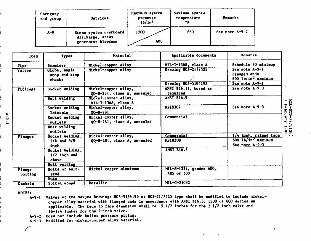
Category iand group Service8
A-9 Steam eystem overboarddischarge,steamgenerator blowdown
tlaximumsystempressurelb/in2
Maximum systemtemperature Remarks
“F
650 See note A-9-2
Item Typea Material Applicabledocuments Remarka
Pipe Seamle88 Nickel-copperalloy NIL-T-1368,class A Schedule80 mfnlmumValves Globe, angle Nickel-copperalloy Drawing803-217752S See note A-9-1
atop end stop Flangedendschecks
,600 lb/in2maximum
mewing 803~5184193 See note A-9-1Fittings Socket welding Nickel-copperalloy, ANSI B16.11,bored ae See note A-9-3
QQ-N-281,class A, annealed requiredButt welding Nickel-copperalloy, ANSI B16.9
1/:MIL-T-1368,clam A
Socket welding Nickel-copperalloy, NS18307 See note A-9-3laterals QQ-N-281socket welding Nickel-copperalloy, Comercialoutlets (/Q-N-281,claam A, annealedButt weldingoutlets
Flangea Socket welding, Nickel-copperalloy, Comercial 1/4 inch. raieed face1/4 and 3/8 QQ-N-281,class A, annealed NS18308 600 Lb/in2 ll~iHUUl
inch See note A-9-3socket welding, ANSI B16*S1/2 inch endaboveButt welding
Flange Bolts or bolt- Nickel-copperaluminum NIL-S-1222,gradee 400,bolting etud 405 or 500
NutsCaaketa Spiral wound 14tallic IIIL-O-21O32
NOTES:A-9-1 Valve@ of the NAVSBA Drawings803-5184193or 803-2177525type shall be modified to includenickel-
copper alloymaterial with flnged enda in eccordnce with ANSI B16.5, 1500 or 600 series asapplicable. The face to face dhenaion shall be 15-1/2inches for the 1-1/2 inch valve and16-1/4 incheofor the 2-inchvalve.
A-9-2 Does not includeboiler pressurepiping.A-9-3 Modified for nickel-copperalloy❑aterial.
/-
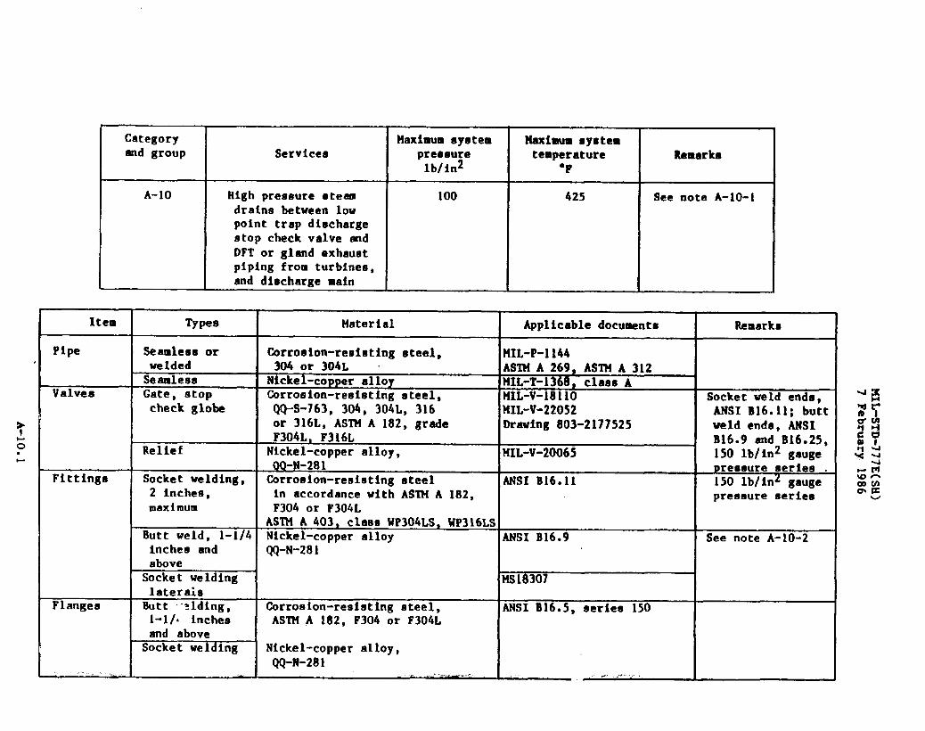
Category Maximumsystem Haximum systemend group Services preaeure temperature Remarke
lb/in2 “F
A-10 High pressureoteam 100 425 See note A-10-1drains between lowpoint trap dischargestop check valve adDFT or gland exhaustpiping from turbines,and diechargemain
Item I Typee
I
check globe
I 2 inches, -
Imaxinmm
I Butt weld, 1-1/4I inches and
Material I Applicabledocuments I Remarka
Corroeion-resistingeteel, lHIL-p-l144 1304 or 304L “ ASTMA269, ASTHA 312Nickel-copperalloy MIL-T-1368,cla8e ACorrosion-resistingsteel, HIL-V-1811O Socketweld ●ride,QQ-S-763,304, 30~L, 316- MIL-V-22052 MSI B16.ll; buttor 316L, ASTM A 182, grade Drawing803-2177525 weld ends, ANSIF304L, F316L B16.9 and BL6.25,Nickel-copperalloy, HIL-V-20065 150 lb/in2 gauge00-N-281 ureeaureseries .Corrosion-reeiatingsteel ANSI B16.11 150 lb/inz gaugein accordancewith ASTM A 182, preesureserieeF304 or F304LASTH A 403, clama WP304LS,WP316LSNickel-copperalloy ANSI B16.9 See note A-10-2QQ-N-281
W3183071
Corrosion-resistingsteel, ANSI B16.5, series 150ASl?lA 182, F304 or F304L
Nickel-copperalloy,QQ-N-281 I I,..-. _. I .. ---- I
categoryand group
A-10, conttd
Services
High pressuresteamdrains betweenlowpoint trap dischargestop check valve mdDFT or gland exhaustpiping from turbines,and dimchargemain
Maximum 5ystpreaaurelb/in2
100
klaxiwtideys:eutemperature
‘F
425
....
Remarks
See note A-10-1
Item Types Material Applicabledocuments , Remarks
Gaskets Spiralwound Netallic HIL-C-21032Flange Bolt, studs Nickel-copperaluminum lUL-S-1222,alloy 500bolttng and nuts HIL-S-1222,grade 400, 40S
~NOTES: .
I s A-10-1 This categoryapplies to drains covered in categoryA-3 only. For draine in systemsother thanL categoryA-3. see the applicablecategory.
A-10-2 Modified for nickel-copperalloy material.
,/
.
Categoryend group Services
B-1 Feed eystema
Maximumsyntempressurelbfin2
600 boilers
1200 boilers
Hexhum eystemtemperature I Remarks
‘F
400 I See notes B-1-land B-l-2
475
Item Types Material Applicabledocuments Remarks
Pipe Seamless Carbon steel MIL-T-20157,ASTMA 106,grade B
Valves Globe, angle and Carbon steel Drawing803-5~lK193 ANSI 600 lb/in2—atop check ASTH A 105 or FIIL-V-22052 pressureeeries
ASTM A 216, grade WCB Drawing803-2177525 shall be used infeed systems for
Gate HIL-V-1811O 600 lb/in2 endbelow boilers.
Relief HIL-V-24332 MSI 900 lb/in2preseureeerieoshall be used infeed systems for1200 lb/in2 boilersexcept for 2 inchesand below 1500lb/in2 series shallbe used
Control 141L-V-18030 Flanged ●ndCheck ML-V-18436
Fittings Butt welding Carbon steel ANSI B16.9AS’IMA 181, class 70ASTM A 105 or ASTM A 234,class WPB
Socketwelding ANSI B16.11Socketwelding Carbon steel Commercialend branchoutletsButt weld end ASTM A 181, class 70 *branch outlets ASTU A 105 or ASTM A 234,1-1/4 inches class WPBand above
r=GY”-r”——.
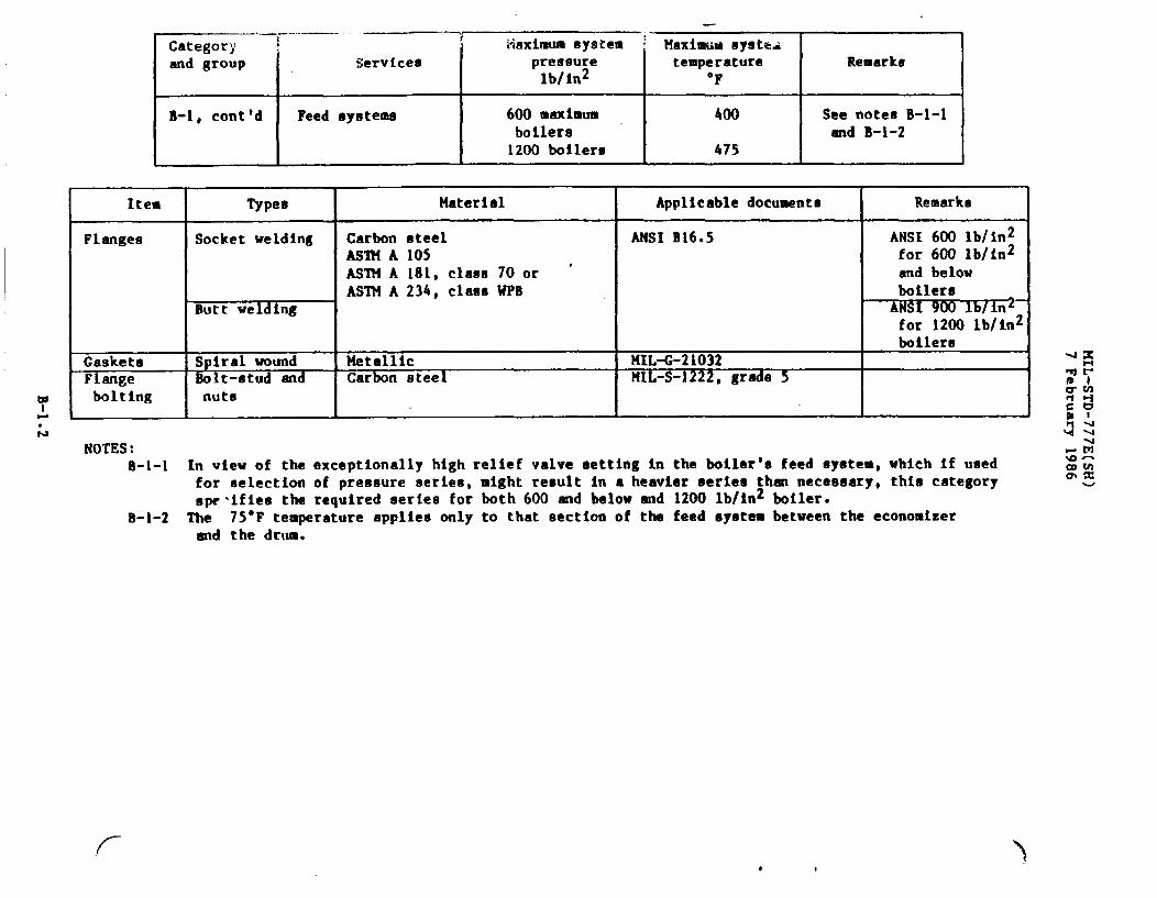
i tiaximumsystemand group
I
Servicee I pressurelb/in2
B-1, cent’d I Feed ayntema 600 maximumboilers1200 boflers
Maximum syste~temperature Remarks
‘F
400 See notes B-1-land B-l-2
475
Item Types Material Applicabledocuments Remarks
Flanges Socket welding Carbon steel ANSI B16.5 ANSI 600 lb/in2AS’IMA 105 for 600 lb/in2AS’RIA 181, class 70 or ‘ and belowASTtlA 234, claeaUPB boilere
Butt welding AMSI 900 lbli 2for 1200 lb/;n2
Gasketa Spiral woundboilere
Metallic lIIIL-G-21032Flange Bolt-stud and Carbon steel 141L-S-1222$ gr~e 5bo1ting nuts
NOTES:B-l-1 In view of the exceptionallyhigh relief valve settingin the boiler$afeed eystem,which if used
for uelectionof pressure seriee,might result in a heavierseries than necessary,thts categoryspe’ifiesthe requiredaerlea for both 600 and below end 1200 lb/in2boiler.
B-1-2 The 75°F temperatureapplies only to that sectionof the feed systembetween the economizerand the drum.
(- ‘1

Categoryand group
B-2
Services
Propulsionplantsaturatedfeedsystem
?faximumsystempressurelblin2
600 to 2050
,
Maximum systemtemperature
“F
300
Remarks
See note B-2-1
Item Types Material Applicabledocumento Remarko
Pipe Seamless Carbon steel ASTUA 106, grade BMIL-T-20157,type E
{alvea Gate Carbon steel IIIL-V-1811O Butt weld ends4 inches and ASTM A 105 orsmaller ASTt4A 216, grade UCB5 through 16 Drawing 803-2177518inches
Globe, angle, Drawing803-2177525 Socketor buttatop end lift weld endscheck, 2 Incheeand smaller2-1/2 inches Drawing803-2177140 Butt weld3and4 inchee Drawing 803-21771415 and 6 inches Drawing803-21771428 inches end MIL-V-22052larger
Swing check MIL-V-18436Relief UIL-V-24332 F1Control
anged endsHIL-V-18030
?itting8 Butt welding Carbon steel MSI B16.9ASlllA 181, class 70ASTM A 105 or ASTUA 234,class WPB
Socket welding MSI B16.11Socket welding Carbon steel Comercialend branch ASTM A 181,class 70outletr3 ASTM A 105 or ASTMA 234,Butt weldingend class WPBbranch outlets ..--.. ~, . .-..

—— -,Categcryand group
B-2, contgd
I Item
IFlanges
kGasketsF angebolttng
L
Services
Propulsionplantsaturatedfeedayatem
Types
Socketweldtng
Butt weldingSpiralwoundBolt-studandnute
WkximuIUsystek-”preesureLb/Inz
600 to 2050
?(axhwasyutemtemperature I Remarks
‘F
300 See note B-2-1
Material Applicabledocuments
Carbon oteel ANSI B16.5ASTM A 105, ASTM A 234, class UPSor ASTM A 181, class 70Netallic MIL-C-21032Carbon steel HILS 122-- 2P 8r~@ 5
Remarka
y NOTES:
k% B-2-1 To be used In conjunctionwith A-3 steam system only. Feed ●ystema for use with other categoryA.-:. steam systems shall be in accordancewith categoryB-1.
B-2-2 Drawing 803-2177525may be used for pressuresup to end including600 lb/in2.
/’--.

.
.
Categoryand group
c-1
Item
Pipe
Valves
Services
Fresh water, chilledwatercondensateand electronicfresh water cooling
Types
Seamless
SeamleanorweldedGate, 2 inchesmaximumGlobe, 2 inchesmaximumCheck, 2 inchesmaximum
Gate, 2-1/2inches andabove
Globe, 2-1/2Inches andaboveSwing check, 2inchee end abov~
ReliefButterflvControl
Ball, 1/4inch - 2-1/2inches,Ball, 3 inchee -6 inchee
Maximumsystempreaaurelb/in2
200
Material
%pper
Xaaa reinforcedplastic
%pper-nickel (90-10)
Bronze
BronzeBronze(nickel-copperalloytrim or 300 series corro-sion-resistingsteel trim)Bronze
Maximum eyatemtemperature
“F
250
‘plicabA”-+iEMIL-T-24107
(see note C-l-1)tIIIL-P-24608 150°Fmaximum
(see note C-l-6)MIL-T-16420
Drawing803-1385714
Drawing803-’4’384536 See note C-l-2
Drawing803-1385721
Drawing803-2177917
Drauing”803-1385623
Drauing803-1385637
HIL-v-24332fiIL-V-24624MIL-v-18030 100 lb/in2maximum
Drawing803-5001003
Drawing803-5001004
KcH
w

..M
Category Maximum system llaximumsystemmd group Services pressure temperature Remarks
lb/in2 “F
C-1, cont$d Freshwater, chilledwater 200 250condensateend electronicfreshwater cooling
*
Item l’ypee Material Applicabledocuments Remarka
Fittinge Silver-brazing Bronze F!IL-F-1183Silver-brazingunionButt welding Copper-ickel (90-10) Drawing803-1385880Welded baee by 90-10 or 70-30 copper-nickel Drawing803-1385912or Welded to copper-eilver brazing comrcial nickel pipe runend outlet bossSocket (bonded) Glaas reinforcedplastic MIL-P-24608 150*Fmaximum
(see note C-l-6)Flangea Socket weld Copper-nickel Draving810-4715319
Silver-brazing Bronze llIL-F-Z~2, class plain, See notes C-l-3150 and 250 pounds and C-1-4
Drawing810-1385892 Special flangesfor butterflyvalves
Socket bonded Glass reinforcedplastic MIL-P-24608 150°Fmaximum(see note C-l-6)
Gasketa Sheet Cloth insertedrubber HH-P-151 See note C-I-5Syntheticrubber !UL-C-1149
O-ring Fluorocarbon tlIL-E-83248.tym I, Claes 1Flange Bolte, etude Silicon bronze MIL-S-1222,grade 655, 661bolting and nuts
,/-
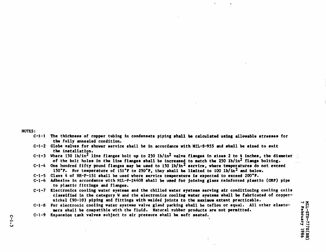
NOTES:c-l-1
C-1-2
c-l-3
c-l-4
c-l-5C-1-6
c-l-7
C-1-8
y c-1-9wL
The thicknessof copper tubingIn condensatepiping●hall be calculatedusing allowablestresses forthe fully annealedcondition.
Globe valvee for shower serviceshall be in accordancewlth141L-S-955rnd shall be ●ked to ●uitthe installation.
Where 150 lb/in2 line flangeebolt up to 250 lb/in2valve flangeein size- 2 to 4 fnchee,the diameterof the bolt holee in the line flange.shall be increaeedto match the 250 lb/in2 flmge bolting.One hundred fifty pound flangesmay be ueed to 150 lb/in2 eervice,where tamperatureado not ●xceed150”F* For temperatureof 151°Fto 250”?, they shall be limited to 100 lb/ln2 and below.
Class 4 of NH-P-151 shall be ueed where servicetemperatureie expectedto exceed 200”?.Mhesive in accordancewith HIL-P-24608ehell be used for joining glaee retifomed Pi-tic (~p) PiPGto plaetic fittinge end flangeo.
Electronicscooling water eyetemeend the chilledwater syetems eervingair conditioningcooling coilsclassifiedin the categoryU and the electronicscoolingwater eyotemsshell be fabricatedof copper-nickel (90-10) piping and fittingewith welded jointe to the meximtm extent practicable.For electroniccooling water eyatenevalve gland packingehell be teflonor equal. All other elasto-mers ehall be compatiblewith the fluid. Naturalrubber producteate not permitted.Expaneion tank valvee eubjectto air preesureshall be ●oft eeated.

.— —
Service8
Fresh water, feedwater end condensate,includingpotable,gae turbinewanhdown
—
Maximumayatem I Maximumsyetea ~Categoryand grouq
c-2
preseure
I
temperature
I
Remarkslb/in2 ‘?
100 I See notes C-2-1, C-2-2and C-2-b
Types I Material Applicabledocument. RemarksItem
Seamle!lll CopperBrago
Seamlessor Copper-nickel(90-10)weldedSeemleea Glasa reinforcedplantic
HIL-T-24107IL T 20160--
HIL-T-16420
FIIL-P-24608
Drewtng803-4384536
0.065 inch minimumwall thickneae
Pfpe
150-Fmaximum(see note C-2-5)See note C-2-3Valvea
s 1
Globe, angle IBronzeI and globe etop I
M Drawing803-1385721141L-V-17547Drawing803-1385637Drawing803-1385714Drawing803-1385541
I globe stop II check and angle I
k5=-i IIIL-v-24624Drawing803-2177917MIL-V-243328.MIL-v-18030.Drawing803Y3OO1OO3
Flanged ends---~e e t!=
[ Ball - 1/2 inch -1Control I
Drawing803-50010046 inches 1Silver-brazing ]BronzeFittings MIL-F-1183
Dfawing810-1385915IIIL-F-1183
Drawing810-1385880Drawing810-1385912
FlangedSilver-brazingunionButt welding Copper-nickel (90-10)Welded baee by 90-10 or 70-30 copper-nickel Welded to copper-
nickel pipe runeilver-brazing Iend outlet boae ISocketbonded lGlassreinforcedplastic HIL-P-24608 150”Fmaximum
See note C-2-> ,_f-
.

Category 14aximum system Heximum systemend group Services pressure temperature Remarke
lb/in2 ●F
C-2, conttd Fresh water, feed water 100 250 See notes C-2-1, C-2-2and condensate, end C-2-4tncludingpotable
c-2-1
c-2-2
C-2-3
C-2-4
C-2-5
c-2-6C-2-7
C-2-8
C-2-9
Item
Flanges
Caskets
Flangeboltlng
NOTES:
Types Material Applicabledocuments Remarks
Sflver-braztng Bronze HIL-F-20042,class plainDrawing~ Specialflangee for
butterflyvalvesSocket weld Copper-nickel Drawing 810-4715319Socket bonded Glees reinforcedpIastic MIL-P-24608 See note C-2-5Sheet Cloth insertedrubber EH-P-151 See note C-2-6
Syntheticrubber MXL-G-1149O-ring Fluorocarbon MIL-R-83248,type I, claa8 1Solte, studs Silicon bronze MIL-S-1222,grade 655, 661and lute
The thicknessof copper tubing in condensatepiping shall be calculatedusing allowableetreeaes,w
-mfor the fully annealedcondition.
*A
The sample connectionbetween the DFT and the samplewater cooler shall be CRES composition304~gw
In accordmce with 141L-P-1144.Connectionto be as close to DFT as possible. ..
Globe valves for shower service shall be in accordancewith ML-S-955 md ehall be sized to suitthe installation.
Where copper tubing is used in potablewater systemswhich supplieswater to equipnmntcontainingcarbonatedwater dispensers,the systemshall have double check valves installed.Mhesive in accordancewith !41L-P-24608shall be used for joining glaaa reinforcedplastic (CRP)pipe to GRP fittingsand flanges.Class 4 of HH-P-151shall be used where service temperatureia expectedto exceed 200”F.Electronicscoolingwater systems and the chilledwater syetema servingair conditioningcoolingcoils classifiedin the categoryW end the electronicscoolingwater oyatemeshall be fabri-cated of copper-nickel(90-10)piping and fittingswith welded joints to the maximum ●xtentpracticable.For electroniccoolingwater and gas turbinewashdown Eystemevalve gland packing shall be Teflonor equal. All other elastomersshall be compatiblewith the fluid. Naturalrubber productsarenot permitted.Expaneion tank valvea subject to air pressureshall be soft seated.

\
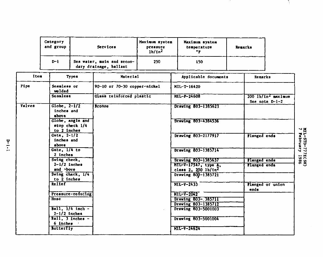
Categoryand group
D-1
Services
Sea water, main and secon-dary drainage, ballast
Maximumsystempressurelb/in2
250
Ueximum eyatemtemperature
‘F
150
Mmarks
J
Item Types Material Applicabledocumente Remarks
Pipe Seamleseor 90-10 or 70-30copper-nickel HIL-T-16420weldedSeamleas Glaas reinforcedplaetic FIIL-P-24608 200 lb/inzmaximum
See note D-l-2Valves Globe, 2-1/2 Bronze Drawing803-1385623
inches andaboveGlobe, angle and Drawing 803-fJ~36atop check 1/4to 2 inches
Gate, 2-1/2 Drawing803-2177917 Flangedendeinches andabove
Gate, 1/4 to2 inches
Drawing803-1385714
Swing check, Drawing803-1385637 Flangedends2-1/2 inches t41L-V=izW7 A Flangedendeand *hove class 2, ~; ;Rn2’Swing check, 1/4 Drawing8~-1385721to 2 inchesRelief HIL-V-2433 Flangedor union
●ndsPressure-reducing HIL-V-2042Hose Drawing803-,385711
Drawing 803-1385712Ball, 1/4 inch - Drawing803-50010032-1/2 Inches
Ball, 3 inches - Drawing 803-50010046 inches -
Butterfly ML-V-24624

——. —Categoryand group I Servicee
D-1, contfd Sea water
Item
Fittings
Flanges
Gaskets
Flangebo1ting
l’ypee
Silver-brazing(includingunione and unionend fittinm)Welding~elded base bysilver-brazingend outlet boasSocket bondedSilver-brazing
Socket bondedButt weldSocketweldSheet
&rlngBolts,studsand nuts
pressure
I
temperature
I
Remarkalb/in2 “F I
250 I 150 I I
Material I Applicabledocuments 1 Remarks
Bronze
IMIL-F-1183
90-10copper-nickel Drawing803-1385880 200 lb/in2 maximumo-1o or 70-30 Drawing810-1385912 Welded to pipe runcopper-nickel I I IGlasereinforcedplastic MIL-P-24608 200 lb/in2 maximumBronze HIL-F-20042 ,;:
Drawing810-1385892 Special flanges for mlbutterflv v;lves Uti
Slassreinforcedplastic HIL-P-24608 200 lb/in2 maximum :?
Oopper-nickel Drawing810-1385992 G:Drawing810-4715319 w
syntheticrubber-m
MIL-R-21252,HIL-C-1149 See note D-l-1 *nam
c Ot R insertedrubber NH-P-151 U.kw
Fluorocarbon MIL-R-83248,type I, ClSe@ 1
Siliconbronze MIL-S-1222,grade 655, 661
NOTES :D-l-1 For uae in piping systemssubject to acid flush oaths.D-1-2 Adhesive in-accord=ce with M~L-P-24608@hall be-used for joiningGRP pipe to GRP fittings and
flanges.
MIL-STD-777E(SH)7 February 1986
.
.+
os 1 1 1 I 1
.
1
D-2.1

1
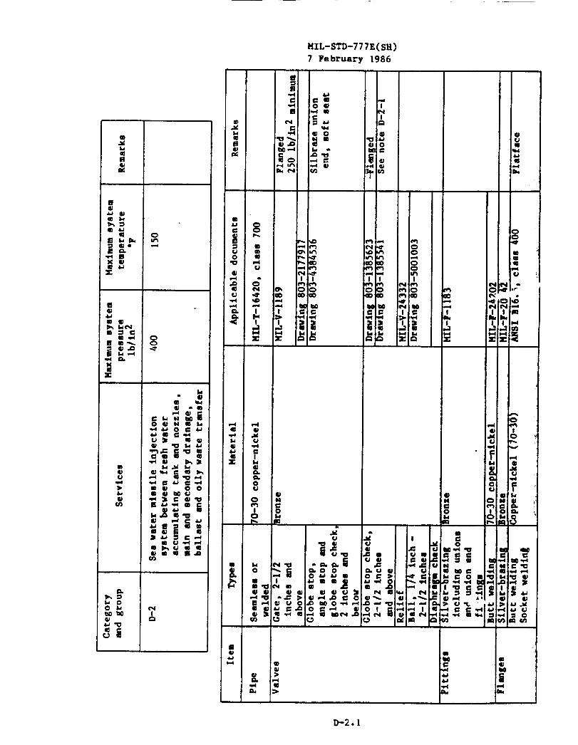
Categoryand group
0-2, Collt’d
Serviceu
*a watermteulle~njectluntayucembetuoenfrrnohwateraccumulatingtankand nozzleu
MaltfmumSysteapreaaura
lb/in2 “: ‘
400
Remarks
Typal I Applicabledocumanca
Shedt ISynth@ticrubbercloth { H1l-P-15iinserted
Synthetic rubber HIL-G-1149tlolta,●tuds S~llconbronze tfIL-S-1222, ljrade 655~5 !ml nutrn
I I
D-2-I 100 Lb/ln2maximum for angieand credostop and utop chockvnlveufor use inen approvedby NAV91!A.
Remarka
!.
conflgurstlon only. 2-1/2inch and lergerglobe and ●ngle, -eyatemaoxceedlng150lb/tn2●hall M of commarc~aldee~gn GE
~E
1:
,.. ,“
,;

I r-J
I\w,.
,k.-
Category Maximumsystem Maximumsystemand group Services pressure temperature Remarks
lb/fn2 “F
D-3 Sea water 50 150
Item ~pes Material Applicabledocumente Remarks
Pipe Seamlessor 90-10 copper-nickel MIL-T-16420,class 50 See note D-3-1welded 70-30 copper-nickel UIL-T-16420 See note D-3-5Seamless Glass reinforcedplastic MIL-P-246011 See note D-3-4
Valves Gate.—
Bronze Drawing803-21~17Drawing803-1385714
Globe, angle Drawing803-1385541and atop check Drawing803-4384536Check, swing Bronze or (90-10) cast copper- Drawing803-1385721or
nickel,MIL-c-20159 Drawing803-1385637Ball, 1/4 - Bronze Drawing803-50010032-1/2 inches .:
Ball, inches - Drawing803-50010046 inchesButterfly ML-v-24624
,.
Fittings Flanged Bronze Drawing810-1385915Silver-brazt.ng MIL-F-l~lJ~(includingunlone and unionend fittings)Welding 90-10 copper-nickel Drawing810-1385880
ANSI B16.9 orANSI B16.11
Welded bane by 90-10 or 70-30 copper-silver-brazing nickel Drawing 810-13859)2 Welded to copper-
. end outlet boos ;Socket bonded
nickel pipe runGlass reinforcedplaetic MIL-P-24608 See note D-3-4
Flanges Silver-brazing Bronze MIL-F-20042Drawing810-1385892 Special flanges for
butterflyvalvesSocket weld Copper-nickel Drawing810-4715319Slip-on 12 Copper-nickel,90-10 MIL-c-15726 See note D-3-2Inches and1argerSocket bonded G1aae reinforcedplastic MIL-P-24608 Spe note D-3-4

.-
Category Maximum 6ystem Maximum systemand group Services pressure tem@rature Remarks
lb/in2 ‘F
D-3, cent’d Sea water 50 150
Item Types !!aterial Applicabledocumente Remarks
Gaskets O-ring Fluorocarbon MIL-R-83248,type I, class 1Sh~/et Syntheticrubber tlIL-G-1149 See note D-3-6
, MIL-R-21252 See note D-3-3Cloth insertedrubber M-P-I 51
flange Bolts, atudo Silicon bronze MIL-S-1222,grade 655, 661bo1tIng and nuts
I I
NOTES:D-3-1 For sizes not covered by MIL-T-16420,pipe fabricatedfrom copper-nickeleheet specifiedin
NIL-C-15726may be used.D-3-2 Slip-on flangeashall be bored to suit outsidediameterof the tube with flange thickneea,
drilling mtd facing in accordancewith claas 50 lb/in2of MIL-F-20042.D-3-3 For use in pipingsystems subject to acid flush path.D-3-4 Adhesive in accordancewith MIL-P-24608shall be uBed for joiningGRF pipe to GRP flttlngB
and flangee.D-3-5 70-30 copper-nickelalloy shall be uned inaldeof
nickel shall be used elsewhere.D-3-6 Gasket in accordancewith tlIL-G-1149shall not be
uges steam for blow-up.
compensatedfuel
used for auctim
tanks and 90-10 copper-
side of sea chest which
●
✎
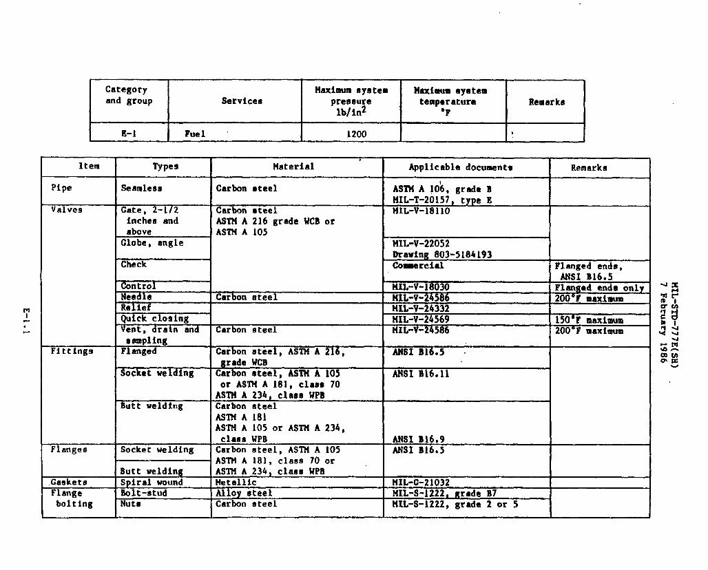
Category Maximumsystemand group Services preeaure
lb/in2
E-1 Fuel 1200
Item
Pipe
Valves
Fittinga
Flanges
.GasketeFlangebolting
Types
Seamless
Gate, 2-1/2inches andaboveGlobe, angle
Check
ControlNeedleReliefQuick closingVent, drain andsamplingFlanged
Socketwelding
Butt welding
Socketwelding
Butt weldingSpiralwoundBolt-studNuts
,Material
Carbon steel
Carbon steel
ASTM A 216 grade WCB orASTM A 105
Carbon steel
Carbon ateel
Carbon steel,ASTM A 216,grade WCBCarbon steel, ASTM A 105or ASTM A 1819 claas 70ASTM A 234, class WPBCarbon steelASTMA 181ASTM A 105 or ASTM A 234,class UPBCarbon steel,ASTM A 105ASTM A 181, class 70 orASTM A 234, class UPBMetallicAlloy steelCarbon steel
Mndmum eyeteatemperature I Remarks
‘F
Applicabledocuments Remarks
ASTMA 10k, grade BlfIL-T-20157,type EMIL-V-1811O
MIL-V-220S2 iDrawing803-5184193l%~rcial Flanged ends,
I ANSI B16.5liIL-V-18030 [Flanged ends onlyMIL-v-24S86 200”F maximumML-V-24332MIL-V-24569 150”F maximumMIL-V-24586 200”F maximum
I
ANSI B16.5 .
ANSI B16.9ANSI B16.5
MIL-G-21032HIL-S-1222,grade B7MIL-S-1222,grade 2 or 5
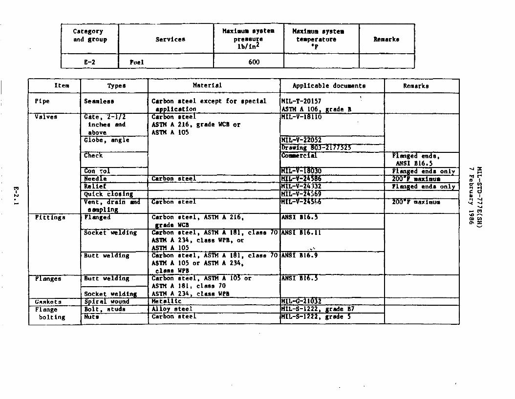
Category Haximm systemand group Services preoeure
lb/in2
E-2I
Fuel I 600
Item
Pipe
Valves
Fittings
Flanges
GnsketsFlangeboltlng
Maximum systemtemperature I Remarks
‘F ITypes
Semlees
Gate, 2-1/2inches andaboveGlobe, angle
Check
~n yol
=dleReliefQuick closingVent, drain andBSmplIngFlanged
Socket welding
Butt welding
Butt weldinu
Socket weldingSpiral woundBolt. studaNuts
Material Applicabledocuments Remarks
tCarbon steel except for special MIL-T-20157application - ASTHA106, grade BCarbon steel HIL-V-1811OASTH A 216, grade WCB or I IASTH A 105
tItlL-V-22052Drawing803-2177525Co=rciel Flangedends,
ANSI B16.5~IL-V-18030 Flangedends only
Carbon steel ~ 20()”FmaximumNIL-V-24332 Flangedends onlyHIL-V-24569
I
Carbon steel MIL-V-245L6 200”Fmaximum
Carbon steel, ASTM A 216, ANSI B1605grade WCB ICarbon steel, ASTH A 181. class 701ANSIB16.11 !ASTM A 234, clasaWPB, orASTM A 105 e’,Carbon steel, ASTM A 181, class 70 ANSI B16.9AS’l?lA105 or ASTHA 234,class UPBCarbon steel, ASTM A 105 or ANSI B16.5AS2?SA 181, class 70ASTH A 234, claseUPBMetallic I!IL+-21032Alloy steel HIL-S-1222,grade B7EELon steel 141L-S-1222, grade 5
Categoryend gr~up
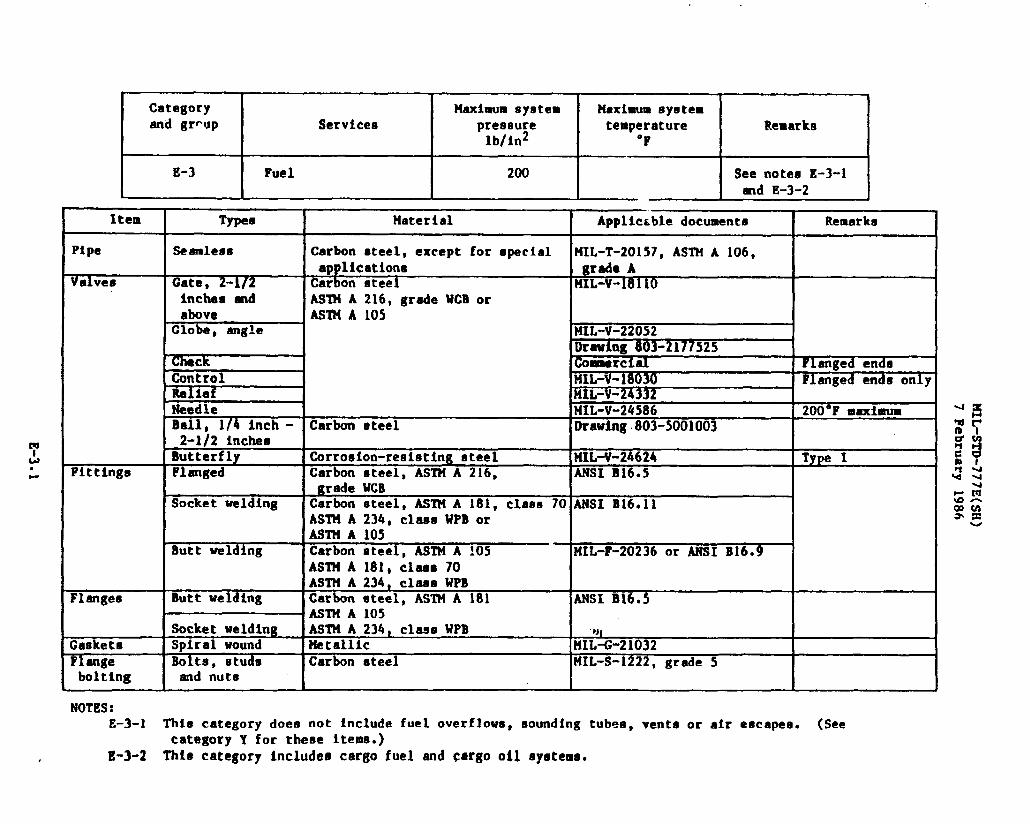
E-3
Services
Fuel
Item I TypesI
PipeIseamle8eJ
Valves Gate, 2-1/2inCheS andabove
Globe, angle
\, ReliefNeedleBall, 1/4 inch -2-1/2 inchesButterfly
Fittinge Flanged
F=Socket welding
Butt wel ing
Flanges Butt welding
bolting I end nuts
NOTES:
200
Remarka
See notes E-3-1md E-3-2
Material [ Applie.bledocfients I Remark~[
Carbon steel,except for specialapplicationCarbon oteelAS’lt’iA 216, grade WCB orASlltA 105
MIL-T-20157,ASTM A 106,grade AMIL-V-1811O
!Coaanrcial FlangedendsMIL-V-i8030 Flangedende onlyifIL-V-24332141L-V-24586 200”F maximum
Carbon steel Drawing.803-5001003
Corroelon-reeistingsteel MIL-V-24624 Type ICarbon steel,ASTM A 216, ANSI B16.5
Carbon steel,AST14A 181, class 70 ANSI B16.11ASTM A 234, classWPB or IAST?lA 105
Carbon steel,ASTM A 105 UIL-?-20236or ANSI B16.9ASTt4A 181,claaa 70 I IASTH A 234, claaa WPB I ICarbon steel,ASTM A 181 IANSIB16.5ASTM A 105 I IASTt4A 234, class WPB f
Metallic MI;-G-21032Carbon steel MIL-S-1222,grade 5
E-3-1 Thie categorydoes not includefuel overflows,soundingtubes,vents or air eacapea. (SeecategoryY for these items.)
t-3-2 Thfa categoryincludescargo fuel end cargo 011 ayatema.
Category i I t’laxim.lln system ] Haxitaum system I
and group
I
Services
I
pressure
I
temperature
I
Remarkslblid “F
I
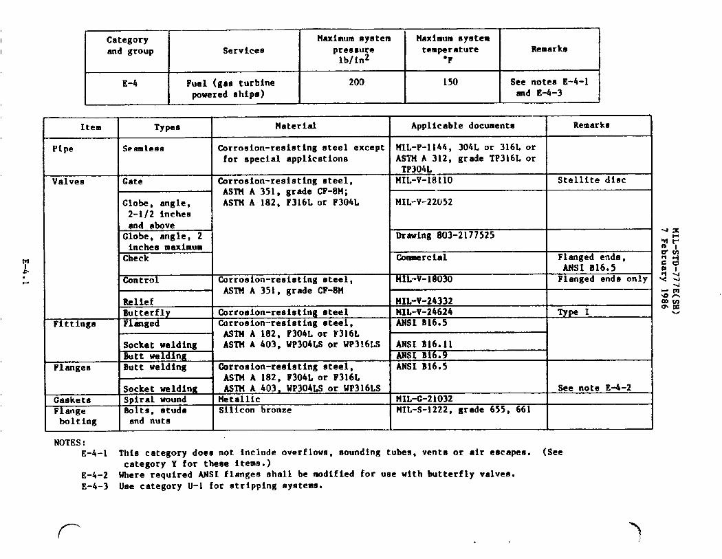
E-4 Fuel (gas turbine 200 150 See notes E-4-1
poweredships) and E-4-3
Item
Pipe
Valves
Ftttinge
Flanges
GasketaFlangebo1ting
NOTES :
Typee Material Applicabledocumente Remarks
Seamless Corrosion-resistingeteel except MIL-P-1144,304L or 316L orfor special applications ASTM A 312, grade TP316L or
TP304LGate Corrotrion-resistingsteel, II4IL-V-1811O Stellitedloc
ASTM A 351, grade CF-8M;Globe, angle, ASTM A 182, F316Lor F304L MIL-V-220522-1/2 inches
Check
Control Corrosion-resistingeteel,
! AWN A 351, grade CF-8MReliefButterfly Corroeion-resistingeteelFlanged Corro9ion-reai6tingsteel,
ASTM A 182, F304L-orF316LSocket welding ASTMA 403, WP304LS or WP316LSButt weldingButt welding Corrosion-reei8tingsteel,
1 ASTM A 182, F304L or F316L
Drawing803-2177525
Commercial Flanged ends,ANSI B16.5
MIL-V-18030 Flanged ends only
?fIL-V-24332HIL-V-24624 VP IANSI B16.5
ANSI B16.11ANSI B16.9ANSI B16.5
Socket welding ASTM A 403~ WP304LSor WP316LS See note E-4-2Spiral wound Metallic MIL-G-21032Bolts, atudo Silicon bronze MIL-S-1222,grade 655, 661and nuts I I I
w
E-4-1 This categorydoen not includeoverflows,aoundlng tubes,vente or air eocapes. (SeecategoryY for these items.)
E-4-2 Where required ANSI flanges shall be modified for use with butterflyvalves.E-4-3 Use category U-1 for stripping systems.
(-

.
Categoryand group Services
F-1 Lubricatingoil
Maximum system Maximum eyetempreesure temperaturelb/in2 “F
150 250
Remarke
See note F-1-l
Item
Pipe
Valves
Fittings
TypeIll
Seamless
=e, angleand e)topcheck,2 inchesmaximumGlobe, angleand stop-check,2-1/2 inchesand largerGatoCheckReliefControlPreeaure-reducinjjButterflyNeedleBall, 1/4 inch -2-1/2 inches
Ventp drain andaarnplingFlanged, 1/2 inchand largerSocket weld
Butt weld
Material
Carbon steel
CarbonsteelASTM A 216, grade WCB orASTM A 105
Corrosion-resi8tingt3teelCarbonsteelCarbonsteel
Carbonsteel
Oarbonsteel,ASTM A 216,grade WCBCarbonsteelKSTtlA 105 or ASTM A 234,class WPBWIN A 181,class 70CarbonsteelIMTM A 105WI?! A 181, C1SS8 70ASTM A 234, class WPB
Applicabledocuments I Remarks
MIL-T-20157,ASTM A 106,grade A or B
MIL-V-22L‘2
MIL-V-18110ANSI B16.34, class 150 FlangedendMIL-V-24332 Flangedends onlyMIL-V-18030
MIL-v-24624’ Type IMIL-V-24586 200”F maximumDrawing 803-5001003
MIL-v-24586 200*Fmaximum
ANSI B16.5, eeries 150
ANSI B16.11
ANSI B16.9IIIL-F-20236
w
I..

Category I Maximumsystem Maximumsystemand group Service13 preesure temperature Remarks
lb/in2 “F
F-1, cent’d Lubricatingoil 150 250 See note F-l-1
Item Typee Material Applicsoledocuments Remarks
Fittings, Socketwelding Co~rc ialcent’d end branch
outletsButt weldingend branchoutlets
Flanges Socketweld, Carbonsteel Commercial l/16-inchraised1/4 inch and ASTM A 181, class 70 face3/8 inch ASTM A 105 orSocketweld, ASTM A 234, class WPB Msl B16.51/2 inchend aboveButt weld
Gaaketa Spiralwound Metallic MIL-G-21032Flange Bolts, studs Carbonsteel ?IIIL-S-1222,grade 5
bolting and nuts
NOTE:F-l-1 Gas turbine lube oil piping shall be corrosion-resistingateel.
—.--
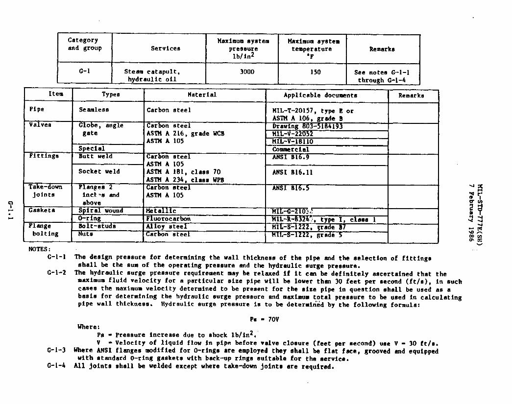
Categoryand group
c-l
4
Maximum system MaximumsystemServices preseure temperature Remarke
lb/in2 ‘F
Steam catapult, 3000 150 See notes G-l-1hvtlrnttlfcn{l thrcmwhC-14
1 I..,------- --- I I 1
. - _-Q.- - - I
Item Types Material Applicabledocuments Remarks
Pipe Seamless Carbon steel FiIL-T-20157,type E orASTH A 106, grade B
Valves Globe, angle Carbon steel Drawing803-5184193gate AST?iA 216, grade WCB t41L-V-22052
ASTM A 105 UL-V-1811OSpecial Commercial
Fittlnga Butt weld Carbon steel ANSI B16.9ASTM A 105
Socket weld ASTH A 181, class 70 ANSI B16.11ASTH A 234, claas WPB
Take-down Flanges 2 Carbon steel MS1 B16.5joints Inct*e and ASTM A 105
aboveGaskets Spiral wound Metallic MIL-C-210-’-~,.
0-ring Fluorocarbon t4XL-R-=, type I, class 1Flange Bolt-studs Alloy steel MIL-S-1222bolting
, ~radeB7Nuts Carbon steel MIL-S-1222, grade 5
NOTES:C-1-l The design pressurefor determiningthe wall thicknessof the pipe and the selectionof fittings
shall be the sum of the operatingpressure and the hydraulicsurge preasura.G-1-2 The hydraulicsurge pressure requirementmay be relaxedif it can be definitelyascertainedthat the
maximum fluid velocity for a particularsize pipe will be lower than 30 feet per second (ft/s), in suchcases the maximum velocity determinedto be presentfor the size pipe in questionshall be used as abagia forpipe wall
Where:PL4-v.
G-l-3 Where ANSI
determiningthe hydraulicsurge pressureand maximum total pressureto bethickness. Hydrauliceurge preaaureia to be determinedby the following
p* - 70V
Preesure Increasedue to shock lb/ln2.
used in calculatingformula:
Velocity of liquid flow in pipe beforevalve closure (feet per second) use V = 30 ft/s.flangesmodffied for O-rings are employedthey shall be flat face, grooved and equipped
with standardO-ring gaskets with back-uprinxs suitablefor the service.
u
C-l-4 All joints shall be welded exceptwhere t&e-d&n joints are required.
Category Maximum system Haximumsystemand group Services pressure temperature Remarks
lb/in2 “F1
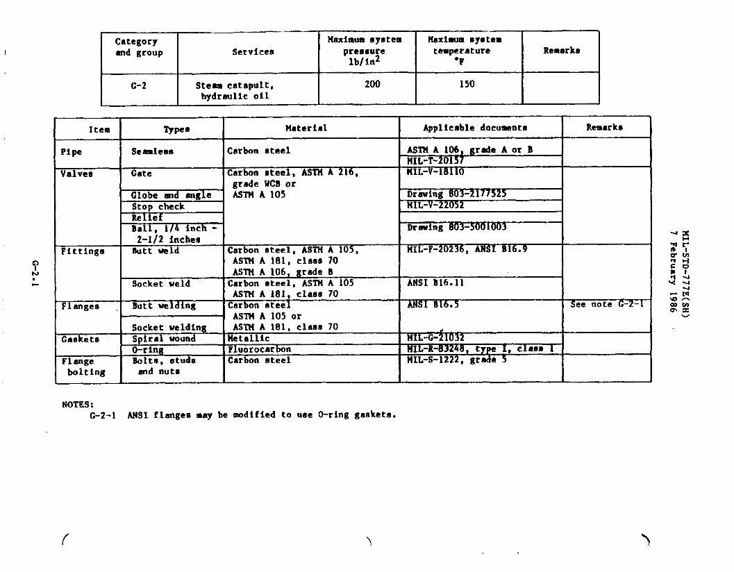
c-2 I Steam catapult,I
200 I 150hydraulicoil I
NOTES:c-2-1 MSI flangesmay be modified to uae O-ring gaskets.
\

z’
~- .< —
i
MIL-STD-777E(SX)7 February 1986
I I I I i I I i I I 1 I I 1 I,i
II . ,1 -
L
G-3.1
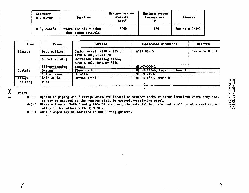
Category Maximumsystem ?laximumsystemand group Services pressure temperature Remarks
lb/in2 “F
G-3, cent’d Hydraulicoil - other 3000 180 See note G-3-1than steam catapult
Item Types Material Applicabledocuments Remarks
Flanges B~~t we~d~ng Carbon steel,AWN A 105 or ANSI B16.5 See note G-3-3ASTM A 181,C~aSO 70
Socket welding Corrooion-resietingsteel,AS’TiIIA 182, 304L or 316L
Sllver-brazing Bronze tiIL-F-20042Gaskets O-ring Fluorocarbon FiIL-R-83248,type 1, claas 1
Spiral wound Metallic MIL-G-21032Flange Bolt studs Carbon steelbolting Nuts
MIL-S-1222,grade 8
L,.
NOTES:G-3-1 Hydraulicpiping and flttingewhich are locatedon weather decks or other locationawhere they are,
or may be exposed to the weather shall be corrosion-resistingsteel.G-3-2 Where unions to NABL DrawingA404734 are used, the material for unionnut shall be of nickel-copper
alloy in accordancewith QQ-N-281.G-3-3 ANSI.flangesmay be modified to use O-ring gasketa.

Categoryand group I Services
0-4 I Hydraulicoil - otherthan steam catapult
Item
Pipe
Valvea
Pittings
Types
Seamlesa
(lateGlobe, angle
Check
Relief
Ball
Samplingandbleedlver-braz$ng
Butt welding
so~ket welding
Unions, ailver-brazingUnion welding
?khum systempressurelblin2
Naximumsystemtemperature
‘F
1500
Material
coDDer
180
Carbon steel
Corrosion-resistingeteel
Carbon steelCarbon steel
X-inure-bronze~uminum-bronzeBronzeCorrosion-resistingsteelCarbon steel or corroaion-resiatingateelCorro8ion-resistingsteelBronze
TEi3weCopper-nickel(70-30)H2L-C-15726Nickel-aluminum-bronzeCarbon steel.ASTM A 105,ASTM A 1,81,close 70 -ASTMA 106,grade BCorrosion-reaistlngsteelASl?lA 182, 304L or 316LCarbon steel,ASTNA 105,ASTN A 181, ChSS 70Corrosion-resistingsteelASTN A 182, 304Lor 316LBronzeNickel-aluminum-bronzeCarbon steel,ASTC4A 105
1Remarks
I
Applicabledocuments!
Remarks
PIIL-T-24107MIL-T-20157.twe E orASTN A 106,-gr-~eBPIIL-P-1144, 304L or 316LASTMA312, TP316Lor TP304LHIL-V-1811ODrawing803-5184193141L-V-22052NIL-V-24109
MIL-V-22687
MIL-v-81940andHIL-V-81940/lDrawing803-1385942Drawing 803-1385945
Drawing810-1385963ANSI B16.9
ANSI B16ell
I
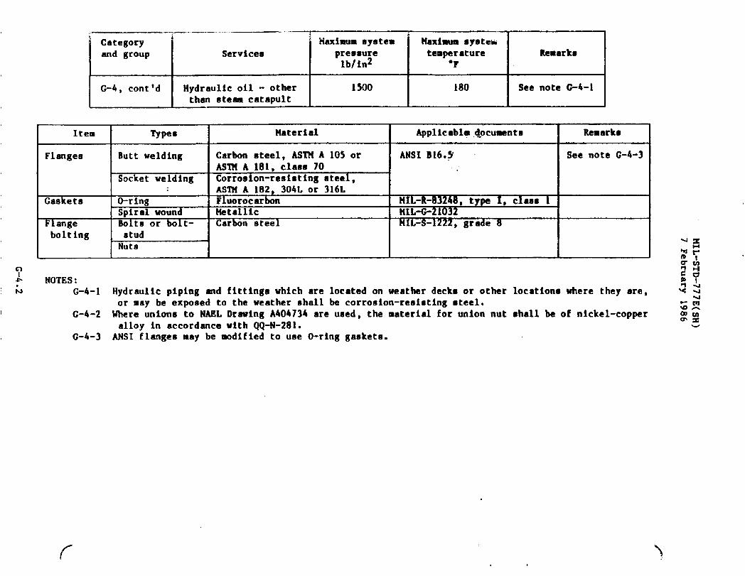
Category ‘ Maximumeystem Maximm systekand group Servicem pressure temperature Remarka
Ib/in2 “?
G-4, cent’d Hydraulicoil - other 1500 180 See note G-4-1than steam catarmlt
Item Types Material Applicable~ocumenta Remarka
Flanges Butt welding Carbon steel, ASTM A 105 or ANSI B16.~ See note G-4-3ASTH A 181, claso 70
Socketwelding Corrosion-resistingsteel,ASTN A 182, 304L Or 316L
Casketn O-ring Fluorocarbon HIL-R-83240, type 1Spiralwound Metallic
1$ clasaUIL-G-21032
k 1ange Bolts or bolt- Carbon steel 141L-S-~ 8bolting
, gradestudNuts
NOTES:G-4-1 Hydraulicpiping and fittingswhich are locatedon weather decks or other locationswhere they are,
or ❑ay be exposed to the weather shall be corrosion-resistingsteel.G-4-2 Uhere unions to NASL DrawingA404734 are ueed, the materialfor union nut ●hall be of nickel-copper
alloy in accordancewith QQ-N-281.G-4-3 ANSI flanges may be modifiedto use O-ringgaskets.
u
f

Categoryand group Servicee
Item I Types
Pipe Seamleaa
1
Valves lGate, 1 inch
PCheckRelief
!T .
BallSamplingandbleeding
Fittings Silver-brazing
Putt we ng
Socketwelding
Take-downjoints
HSximumeystempreaaurelb/in2
900
Maximumsystemtemperature Remarks
‘F
180 See note G-5-1
llaterial I Applicabledocuments
Copper IIIL-T-24107Carbon steel MIL-T-20157,type ECorrosion-resistingsteel t41L-P-1144, 304L or 316L
ASlliA 312, TP316Lor TP304LCarbon steel HIL-V-1811O
Carbon steel Drawing803-5184193HIL-V-22052
Bronze MIL-V-24109HIL-V-18436
BronzeCarbon steelCorrosion-resistingsteel tfIL-V-22687
HIL-V-81940and!fIL-V-81940/l
Bronze Drawing803-1~Copper-nickel(70-30) Drawing 803-1385945tlIL-C-15726Bronze Drawinu~41Carbon steel,ASTN A 1059 ANSI m 9.AS’It!A 181,class 70,ASTN A 106,grede B, or ANSI B16.11corrosion-resistingsteel,AST14A 182, 304L, or 316L-Bronze Drwing 803-1385946Nickel-aluminum-bronze Drawina 803-1385943.Carbon steel,ASTM A 105 NAEL”Dr~~ng-A404134Carbon steel,ASTHA 105, ANSI B16.5ASTH A 181,claae 70, orcorrosion-resistingsteel,ASTHA 182, 304Lor 316L
Remarks
2 ~nchee maximum
See note G-5-2See note G-5-3
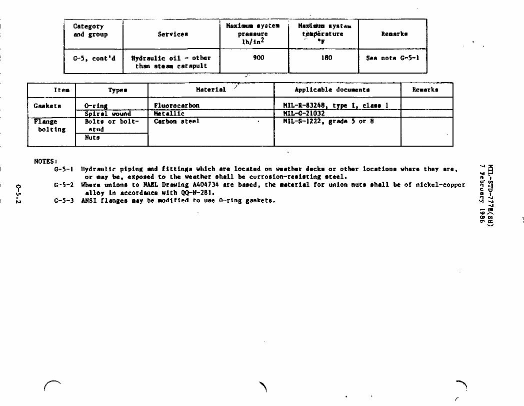
r—-. — . ..——. —.... . ..
I Category 1 1 ~imum 8y&i; ‘“-Ha@i@ systemiend group Services pressure tbbpiirature Remarks
lb/in2.-,
‘F
G-5, cent’d Hydraulicoil - other 900 180 See note G-5-1than ateem catapult
~.
I Item I Types I Material ‘“ I Applicabledocuments I Remarks I
I Gaskets *ring Fluorocarbon HIL-R-83248,type 1, class 1Spiral wound &t&llic MIL-C-21032
Flange Solts or bolt- Carbon steel , IIIL-S-1222,grade 5 or 8I bolting I stud I I I II I Nuts I I I INOTES:
I G-5-1 Hydraulic piping and fittingswhich are locatedon weatherdecks or other locationswhere they are, :~or may be, exponed to the weather shall be corrosion-reeistingsteel. tBl
I:
C-5-2 Where Unions to NASL Drawing A404734are based, the materialfor union nuts shall be of nickel-copper % walloy in accordancewith QQ-N-281.
$?
I L G-5-3 ANSI flanges may be -dified to use O-ring gaakets. 4:
SEawl~ul
7’,

Categoryand group
G-6
Item
Pipe
Valves
Fittings
Tk -down;o;nts
Services
Hydraullcoil - otherthan steam catapult
?faximumsystempressurelb/in2
——
Maxlr.lmsystemtemperature
“Q
180
Remarks I
Types Material Applicabledocuments Remarks.
Seamless Copper MIL-T-24107Carbon steel MIL-T-20157, ASlllA 106,
grade BCorrosion-resietingsteel NIL-P-1144, ASTtlA 312,
316Lor 304LGate Bronze MIL-V-1189
Drawing803-1385714Carbon steel HIL-V-18110
Globe, angle Bronze ~rewing 803-4384536Carbon steel Drawing803-2177525
!!IL-V-22052Swing check Bronze Drawing803-1385721Relief Bronze or steelBampl1ng and MLV H1940-- dbleed &L-v-81940ZBall, 1/4 inch - Cmroeion-resimtingsteel Drawing803-50010032-1/2 inches
—
Silver-brazing Bronze rIiIL-F=l183Butt welding Carbon steel,AST?4A 105, MIL-F-20236
IASTt+A 181,clasa 70
I
ANSI B16.9ASTN A 106,grade B orcorrosion-remtatingsteel,ASTH A 182,304L or 316L
Socket welding Awl B16.11Union, silver- Bronze HIL-F-1183
%k=-’ t41L-F-20042brazingFlanged Carbon steel,ASTM A 105, ANSI B16.5 See note G-6-2
AST?IA 181,clasa 70 orcorroeion-reaiatingsteel,
I ASTMA 182,304Lor 316LUnions, welding lCarbon steel,ASl14A 105 NAEL DrawingA404734 See note G-6-3
I
..
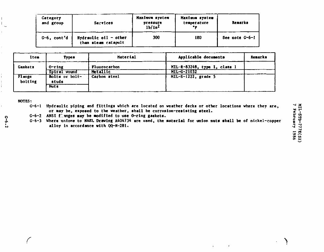
Categoryand group
G-6, conttd Kydraulicoil - other 300than steam catapult
HUximua systemtemperature
“F
180
Remarka
See note G-6-1
Item
Gaakets
Flangebolting
Types
O-ringSpi ral woundBolts or bolt-studsNuts
tlaterial I Applicabledocu~nts
%-R-83248, ty~ 1, claas 1‘I.-c-21032L-S-1222, grade 5
NOTES:G-6-1 Hydraulic piping and fittingswhich are locatedon weather deckn or other locationawhere they are,
or may be, exposed to the weather,shall be corrosion-resistingsteel.G-6-2 ANSI f~.angesmay be modified to use O-ring gaskets.G-6-3 Where unions to NAEL Drawing A404734 are used, the material for union nuts shall be of nickel-copper
alloy in accordancewith QQ-N-281.
r

MIL-STD-777E(SE)7 February 1986
G-7.1
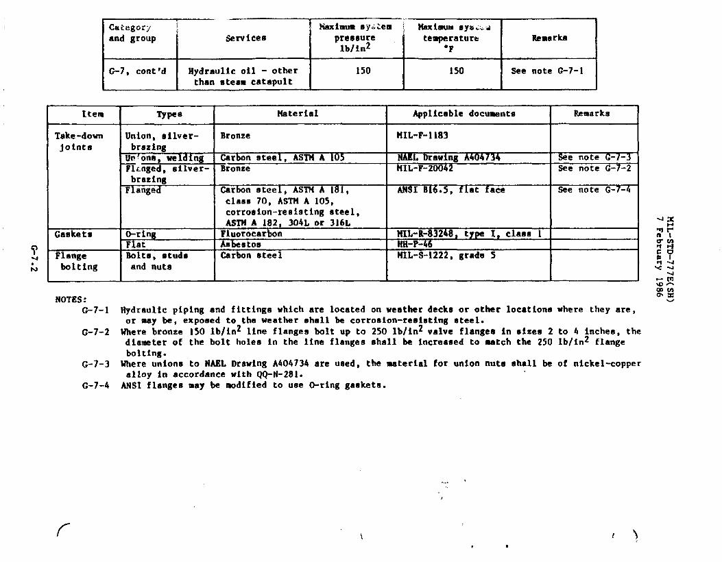
Ctvf%garyand group
G-7, cent’d
—..
service8
Hydraulicoil - otherthan steam catapult
.-Maximumsy~~em ~ MaximumOylsi.d
Ipressure ‘ temperature Remarkslb/in2 “F
150 150 I See note G-7-1
Item
Take-downjoints
Gasketa
Flangebolting
NOTES:G-7-1
G-7-2
G-7-3
G-7-4
Types
Union, ailver-brazing
Ucfona,welding~~nged, 6ilver-brazingFlanged
O-ringFlatBolts,studsand nuts
Material Applicabledocumente
Bronze HIL-F-1183
Carbon steel, ASTU A 105 NAEL DrawingA404734%onze CIIIL-F-20042
Carbonsteel, ASTM A 181, ANSI E16.5,flat faceclass 70, ASTM A 105,corro8ion-reni9tingsteel,ASTN A 182. 304L or 316L—Fluorocatbo; HIL-R-83248,type I, clase 1Asbestos HH-P-46Carbon steel UIL-S-i222,grade 5
I
Remarks
See note G-I-3See note G-7-2
See note G-7-4
w
Hydraulicpiping and fittingswhich are locatedon weatherdecks or other locationswhere they are,or may be, exposed to the weather shall be corrosion-reeistingeteel.Where bronze 150 lb/in2 line flangeabolt up to 250 lb/in2valve flanges in sizes 2 to 4 inches, thediameterof the bolt holes in the line flangesshall be increasedto match the 250 lb/in2 flangebolting.Where unions to NAEL DrawingA404734are used, the materialfor union nuts shall be of nickel-copperalloy in accordancewith QQ-N-281.ANSI flangesmay be modifiedto uee O-ringgasketa.
f
,... *
\*
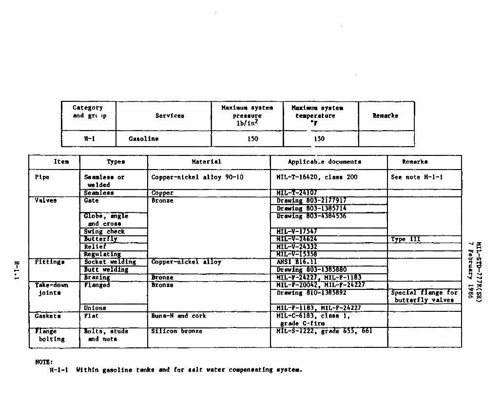
Category Maximum system Maximqm systemand gr(lp Servlcee pressure temperature Remarks
lb/in2 ‘F
II-l Caaoline 150 150
Item I I Material I Applicabledocument,
Pipe
Valves
Fitting@
Take-downjolnta
Unione t41L-F-1183,tiIL-F-24227Gaskets Flat Buns-N and cork MIL-C-6183,class 1,
grade C-fire~ ange Bolts, studs Silicon bronze MIL-S-122 65~bolting
2, grade *amd nuts
NOTE:H-l-1 Within gasoline tanks and for salt water compensatingsystem.
Remarks
J
-4
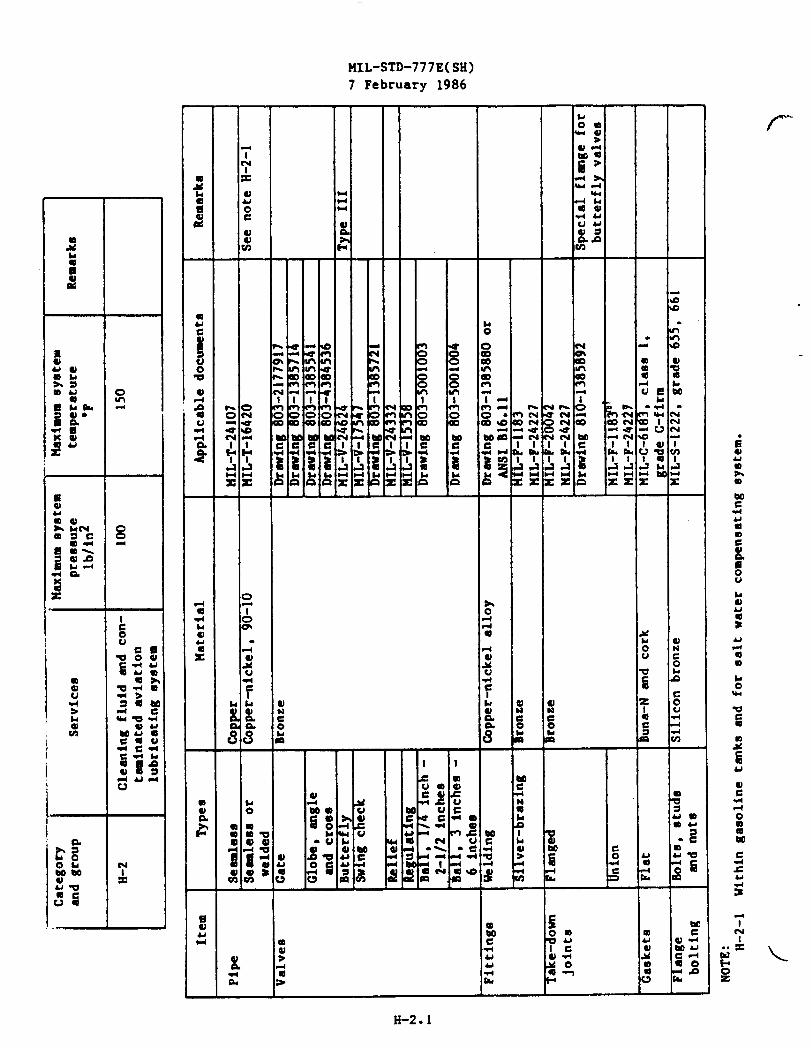
—.
IqIL-sTD-777E(sH)
7 February 1986
l--
0in
f-
H-2.1

o0
00m
A
MIL-STD-777E(SH)7 February 1986
aJ
5&
I-1.1

I Category Haximumeystem MaximumsystemI and group .Servicee preseure temperature Remarks
lblinz ‘F
1-1, cent’d JP-5 200 100 See notes 1-1-1md I-l-2
Item Types Materfal Applicabledocuments Remarks
Gaskets Sheet Buns-N and cork HIL-c-6183,claas 1,gradeC-firm
F1ange Bolts, studs Silicon bronze 141L-S-1222boltIng
, gradeand nuts
NOTES:1-1-1 See category U-1 for those sectionsof tank strippingwhich dischargeoverboard.I-l-2 “This category includeecargo JP-5 systems. The cargo JP-5 pipingwithin convertiblecargo tanks
(tkse intended for selectivestowageof JP-5 fuel) shallbe in accordancewith this category.
(
w
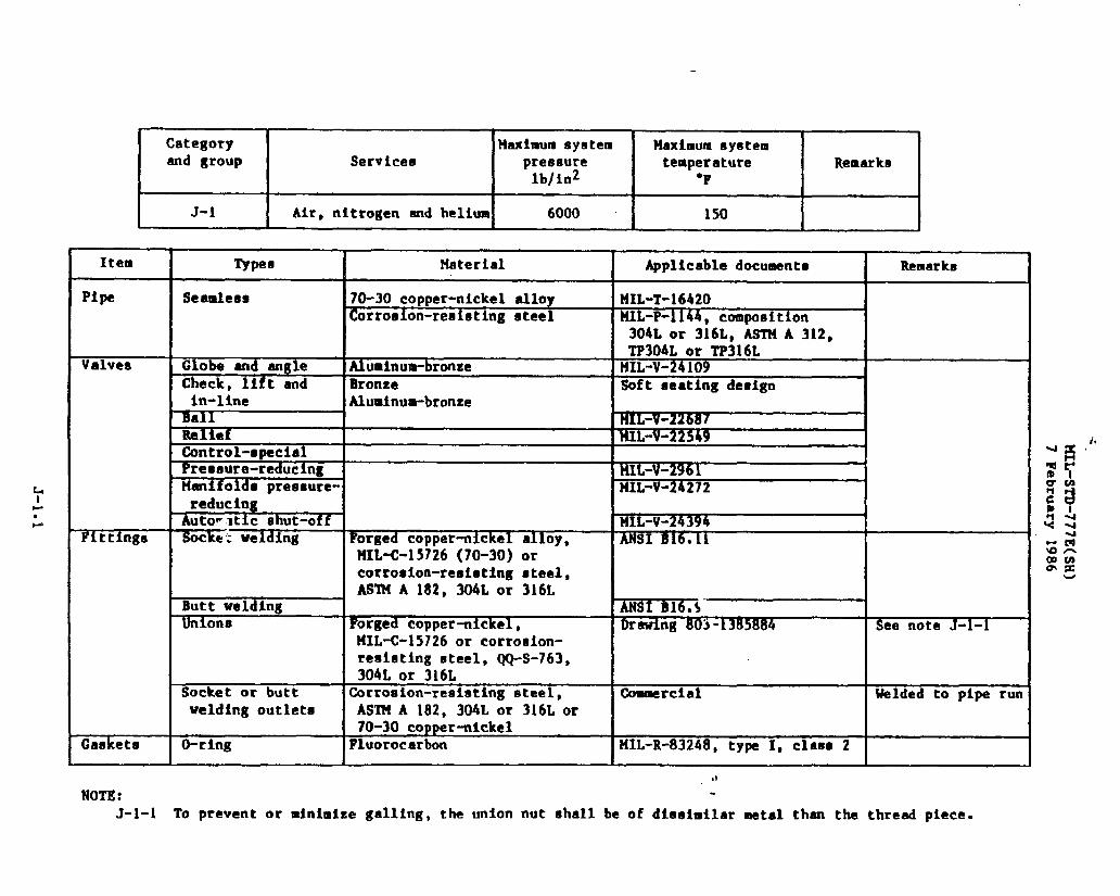
Category Maximum system Heximum systemand group Services pressure temperature Remarks
lb/in2 “F
J-1 Air, nitrogen end heltum 6000 150
i.
,1
NOTE: .
J-1-1 To prevent or minimizegalling, the union nut shall be of dlasimilarmetal then the threadpiece.
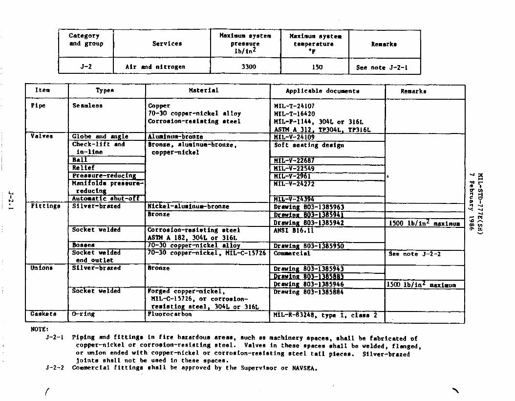
Item
Pipe
Valves
Fittings
Unions
Gaskets
NOTE:J-2-1
J-2-2
Category Maximumsystem Maximumsystemmd group Services pressure temperature Remarks
lb/in2 “F
J-2 I Air and nitrogenI
3300I
150I
See note J-2-1
Typee Material Applicabledocuments Remarks
Seamless Copper HIL-T-2410770-30 copper-nickelalloy HIL-T-16420Corrooion-reuimtingsteel MIL-P-1144,304L Or 316L
ASTlfA 3129 TP304L,TP316LGlobe end angle Aluminum-bronze M1L-V-24109Check-lift and Bronze, aluminum-bronze, Soft seatingdesign
==1in-line copper-nicke1
BallReliefPressure-reducnMani o s pressure- K!!==reducfnu I I I
Automati~ ehut-offJ (
UIL-V-24394Silver-brazed Nickel-aluminum-bronze Drawing 603-1385963
Bronze tlrewin~803-1385941Drawing 803-1385942 1500 lb/ln2 maximum
Socket welded Corroeion-resisting●teel MSI B16.11ASTUA 182, 304Loc 316L
Boeeee 70-30 copper-nickelalloy Drawing 803-1385950Socket welded 70-30 copper-nickel,UIL-C-15726 ~rcinl See note J-2-2end outletSilver-brazed Bronze Drawing 803-1385943
Drawinu 803-1385883Drawing803-1385946 1500lb/in2 maximum
Socket welded Forged copper-nickel, Drawing 803-1385884MIL-c-15726,or corroaion-reaistingsteel, 304Lor 316L
O-ring Fluorocarbon MIL-R-83248,type I, class 2
Piping and fittingsin fire hazardousareas, ouch as machineryapacea,ehall be fabricatedofcopper-nickelor corroeion-reaiotingsteel. Valvea in these spacea shall be welded, flanged,or union ended with copper-nickelor corrosion-reeiatingsteel tail pieces. Silver-brazedjoints shall not be used in these spaces.Commercial fittingsshall be approvedby the Supervisoror NAVSEA.

Item
Pipe
Valves
h&●
w FI ttingl!l
Unions
Gaekete
NOTES:J-3-1
J-3-2
Category Maximum system Maximum eyetemand group Services pressure temperature Remarks
lb/in2 ‘FI
J-3 Air and nitrogenI
600I 150
ISee note J-3-1 I
Typee
Seamless
Globe, mgleand checkBall, 1/4 inch -2-1/2 inches
ReliefPressure-reducingF!anifol~s,pressure-reducingAutonatlc ehut-offSilver-brazed
Socket weld
BossesSocket Weldingend outletSilver-brazed
Socket welded
Material I A@fcable documents
Copper HIL-T-24107,ASTM B 8870-30 copper-nickelalloy KfL-T-i6420 .,Corro8ion-resistingsteel HIL-P-1144,304L or 316L
ASllIA 312, TP304L,TP316LBronze, aluminum-bronze MIL-V-24109,soft-eeating
designDrawing 803-5001003
MIL-v-24394Bronze Drawinx 810-1~6
HIL-F-1183Corrosion-resintlngateel ANSI B16011AS’I14A182, 304L0 or 316L
copper-nickelalloy Drawing 803-138595070-30 copper-nickel, CommercialliIL-C-15726Bronze Drawing 810-1385859
Drawing 810-1385889t41L-F-1183
Forged copper-nickel, Drawing 803-1385884141L-C-15726,or corroaion-
Remarks
400 lb/lnz eeximum
See note J-3-2
400 lb/inzmaximum
I resistingsteel, 304L or 316LI IO-ring Fluorocarbon IMIL-R-83248,type I
I I claaa 1.~.
Piping and fittfngm in fire hazardousareas, such as machinerys,sees,shall be fabricatedofcopper-nickelor corrosion-reeistingsteel. Valves in these spa M shall be welded, flanged,or union ended with copper-nickelor corroelon-reuietingsteel ta~.1piecee. Silver-brazedjoints ehall not be used in these epacea.Commercialfittings shall be approvedby the Supervisoror NAVSEA.

——.. —.. .—Ci3tegoryand group
J-4
Item
Pipe
Valves
Fittings
Unions
F1angee
——. . —
Services
Air and nitrogen
tlaximumsystem Maximumsyuwmpressure temperature Remnrkalb/in2 ‘F
200 I 150 I See note J-4-1
?ypee i Haterial
Seamlew3 ItipperCopper-nickelelloyCorroeion-reeistingsteel
Glaee reinforcedplasticGate Bronzesw$n~ check
=
Globe, ang e,needle, stopcheck and checkPreeaure-reuc ng
eAutomaticshut- 1offBall, 1/4 inch -2-1/2 inchesSilver-brazed Bronzehcket welded Corrosion-resistingsteel,
ASTM A 182, F304L, F316LSocket welded end 70-30 copper-nickel,outlet HIL-C-15726Socket bonded Glass reinforcedplasticSilver-brazed BronzeButt and socket Corrosion-reaistinasteelwelded or copper-nickel(~0-30)Silver-brazed Bronze
1
Socketwelded lCorrosion-resit3tingsteelASTM A 182, F304L,-F316L70-30 copper-nickel
Socket bonded Glass reinforcedplastic
Applicabledocuments
MIL-T-24107,AST?tB88rIIL-T-16420141L-P-1144,304L or 316LAST14A 312, TP304Lor TP316LttIL-P-24608Drawing803-1385714
%%-%HW---
MIL-V-24384MILV 22549--
MIL-v-24394
Drawing803-5001003
HIL-F-1183MSI B16cll
Commercial
MIL-P-24608t41L-F-1183Drawinge803-138$8849810-1385888IIIL-F-20042,ANSI B16.24-MSI B1605
ANSI B15.5, clase 150HIL-P-24t,08
Remarks
See note J-4-3
Soft seat deeign,except needlevalve
See note J-4-2
1’
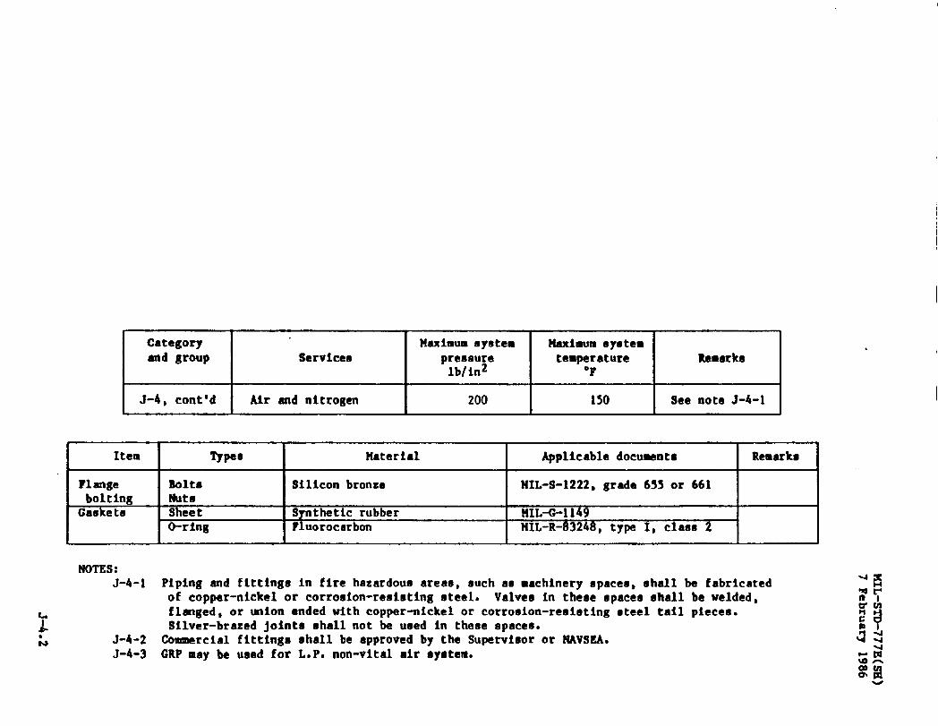
Category tI!aximumsystem Haximum eystemand group Services pressure temperature Remarks
lb/in2 *F
J-4, cent’d Air and nitrogen 200 150 See note J-4-1
v
Item Typee Material Applicabledocuwnta Remarka
?1ange Bolts Siliconbronze HIL-S-1222,grade 6S5 or 661bolting NutsCaskets Sheet Syntheticrubber HIL-O-1149
O-ring Fluorocarbon NIL-R-83248,type 1, class 2&
NOTES:J-4-1 Piping and fittingsin fire hazardousareas, such aa machineryspaces,shall be fabricated
of copper-nickelor cortoaion-reaietingsteel. Valvee in these spacesshall be welded,flanged,or union anded with copper-nickelor corrosion-reoietingeteel tail pieces.Silver-brazedjoints shallnot be used in theee epaces.
J-4-2 Commercialfittingsshall be approvedby the Supervisoror NAVSSA.J-4-3 GRP may be used for L.P. non-vitalair system.
u

J-5 Air, ●ircraftetarting 150and cooling,bleed-offand 20.2 lb/in2absolute nystems
Maximums~etewtemperature
‘P
550
Remarks
Item Types Material Applicabledocuments Remarks
Pipe Seamleaa Carbon steel , HIL-T-20157ASI14A 106, grade A or B
Valves Gate, 1 inch Carbon steel MIL-V-18I1Oand above ASI?4A 105
Control llIL-V-18030 Flanged ●nde only,ANSI B16.5
Relief ?lIL-V-20065Fittings Butt welding Carbon steel HIL-F-20236,ANSI B16.9
ASTUA 105,AS’l?fA 181, class 70, orASTMA 234, class WPB
Socket welding Carbon steel ANSI B16*IIASTN A 105,AS’I?iA 181, claes 70, orASTHA 2341 class bJPB
Flanges Carbon steel ANSI B16.5 Flat faceASTHA 105,ASTM A 181, class 70, orAS’I?lA234, claaa UPB
Gaekete Sheet timmercial Commercial;. 1/16 inch thickFlange Bolts or bolt- Alloy steel HIL-S-122i,grade B7bolting stud
Nuts Carbon steel ?41L-S-1222,grade 5
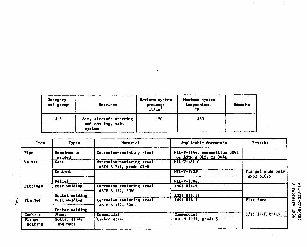
,
ICategoryand group
EJ-6
Service6
Air, aircraftstartingand cooling,mainsystem
Maximum system
I
Maximum systempressure temperature
I
Remarkslb/in2 “F
150
I
450
I
Item Types Ilaterial Applicabledocuments Remarks
Pipe Saamleeoor Corrosion-resimtingsteel lfIL-P-1144,composition304Lwelded or A8TUA 312, TP 304L
Valves Gate Corroston-reeimtingsteel I’IIL-V-18110ASl?iA744, grade CF-8
lh3ntr01 ML-V-W Flangedenda onlyANSI B16.5
Relief tlLL-V-20065Fittings Butt welding Corrosion-resistingsteel ANSI B16.9
ASTM A 182, 304LSocket welding ANSI B16.11
Flanges Butt welding Corrosion-resistingsteel ANSI B16.5 Flat faceASTM A 182, 304L
Socket weldingGaskets Sheet Commrcial Commercial 1/16 inch thick
F1ange Bolts, studs Carbon steel llIL-S-1222 5bolting
, grade-d nute

——..—.. . —.~ Category‘:
.— .—.. .Maximumsystem ~ ;+aximu~~yst~~
and group %rvicea preaoure temperature Remarkelb/in2 “F
J-7 Air, prairie-meeker, 100 600 See note J-7-1. gas turbinestarting
Item Typee Material Applicabledocuments Remarks
Pipe Seamless Copper HIL-T-24107Seamlemaor tipper-nickel MIL-T-16420 See note J-7-2welded Corrosion-resistingsteel HIL-P-1144or ASTHA 312,
TP321 or TP347Valves (Me Bronze Drawing803-2177917
Globe, angle Drawing803-1385541 425-F maximum-d atop check Dr i g 803-431m3i3Swing check HI&:17547 2-1/2 inches and
aboveDrawing803-1385721 2 inches and below,
425-F maximumButterfly tllL-V-24624 See note J-7-3
Drawing810-1385892 Special flanges forbutterflyvalvee
Automaticahut- UIL-V-24394 2 incheo and belowoff
Fitttnge Silver-brazed Bronze llIL-F-1183 See notes J-7-4 and
Socketwelded--
70-30 copper-nickel, Comercialend outlet HIL-C-15726Socketwelded Corrosion-resistingsteel, ANSI B16.11Butt welded ASTHA 182, 316, 321 or 347 ANSI B16.9
Flangea Silver-brazed Bronze MIL-F-20042Butt and eocket 70-30 copper-nickelor ANSI B16.5,claeo 300welded corroeion-reeietingsteel
Unfons Silver-brazed Bronze IIIL-F-20042Butt and socket 70-30copper-nickelor Drawings803-1385884,welded corrosion-resistingsteel 810-1385888
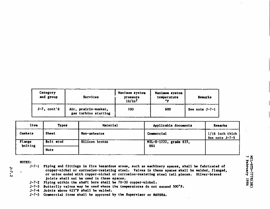
..
Category Maximum system Maximum syetemend group Servlcea pressure temperature Remarks
lb/in2 “F
J-7, cent’d Air, prairie-masker, 100 600 See note J-7-1gae turbine starting
●
Item TypeB Meterial Applicabledocuments Remarks
Gaskete Isheet I Non-asbestos I Coanerclal I 1/16 inch thick I
Flange Silicon bronzeINIL-S-1222,grade 655,
bolting 661 I INuts
I
NOTES:
u J-7-1& .●
N
J-7-2J-7-3J-7-4J-7-5
Piping and fittingein fire hazardouaareae, much as machineryepacee,ehell be fabricatedofcopper-nickelor corronion-resistingsteel. Valvee in theoe spaceo ohall be welded, flanged,or union ended with copper-nickelor corrosion-reeietingsteel tail pieces, Silver-brazedjoints shall not be used In these spaces.Piping within the Shaft bore shall be 70-30 copper-nickel.Butterfly valvesmay be used where the temperaturesdo not exceed !MIOaF.Jointa above 425°F shall be welded.Cotmnercielitems shall be approvedby the Supervisoror NAVSEA.

——- ...—. . -— ..b- —— ..——,. .
3 Category i ‘ Maximumsystem ‘ ‘Maximumsyate~end group Services pressure temperature Remarks
lbfinz “F
J-8 Air deballaet 50 400
Item Typee Uaterial Applicabledocuments Remarks
Pipe Seamleaaor 90-10 copper-nickel MIL-T-16420,claea 200welded
Valve9 Gate Bronze Drawing803-2177917 ‘Drawing 803-1385714
Globe and angle Drawing803-1385541Drawing803-4384536
Check, suing Drawing8u3-1385637Drawing803-1385721
Butterfly NIL-V-24624 See note J-8-2Relief ?41L-v-20065Control MIL-V-18030
Fittings Silver-brazing Bronze MIL-F-1183Butt welding 90-10 copper-nickel Drawing803-1385880Socket welding ANSI B16C11Unions, eilver- I)ronze MIL-F-1183brazing
Flanges $Ilver-brazing Bronze MIL-F-20042Drawing 810-1385892 Special flangee for
butterflyvalveaButt weld 90-10 copper-nickel, Drawing810-1385992
KLL-C-15726Slip-on See note 1
Gasket Sheet Asbestos HH-P-46 1/16 Inch thickFlange Boita, studs Siliconbronze MIL-S-1222,grade 655, 661bolting and nuts
NOTB:J-8-I Slip-on flangesshall ~ bored to suit the outeidediameterof the tube with flange thicknees,drilling
and facing in accordancewith IIIL-F-20042.J-8-2 Valve must be suitable for a temperatureof 400”F.
,

\
Categoryand group Services
Air: Gas turbinebleed,anti-icing
Maximumsystem Max ❑um oystempreaeure teloerature Remarkslblin2 ‘Q
250 950
Item Type8 Material Applicabledocuments Remarks
Pipe Seamless Corrosion-renietingsteel tIfIL-P-1144or ASTMA 312,TP321 or TP347
Valvet3 Gate Corrosion-reeietlngsteel, HIL-V-I811O,modified See note J-9-1ASTM A 182, F321 or F347
Globe, lift Drewing,803-5184193,check HIL-V-22052,mdifiedSwing check CcmaerclalBal1 Drawing803-5001003or See note J-9-2
commercialPittings Socketwelded Corrosion-reeistinguteel, ANSI B16.11
ASl14A 182, F321 or F347Butt welded ANSI B16.9
Take-down Flanges Corrosion-reaiatingsteel, ANSI 916.5joints ASTMA 182, F321 or F347Gaskets Spiralwound Metallic MIL-G-21032Flange Bolt studs Alloy eteel 141L-S-1222,grade B16bolting -Nut8 MIL-S-1222D gr~e 4
NOTE:J-9-1 CompositionE: Corrosion-resistingsteel F321 or F347 (valve backsedtand guide to be w).
This requirementwill be part of the classificationof UIL-V-1811O“hnd141L-V-22052.J-9-2 CommercialItems shall be approvedby the Supervisoror NAVSEA,


Category “Maximumsystemand group Services . premure
lblinz
K-1 Gaseous oxygen, 4500outeide hull
Ipipe I’em’e”\Valves Globe and angle
L@=y SocketweldinEw Unions Silver-brazing●
150
I
See notes K-l-1tmd K-l-2
Material I Applicabledocuments I Remarks 1
Copper-nickel 1 MIL-T-16420Copper r41L-T-&4107 3000 lb/ind
maximum IBronze,aluminumbronze, Soft seat designcopper-nickel NIL-v-24109Nickel-copperalloy
HIL-V-24336Nickel-aluminumbronze Drawing810-1385963
+nion end-
3000 lblin~Bronze Drawing 803-1385941 maximumNickel-copperalloy ANSI B16.11Bronze Drawing 803-1385943 3000 lb/inZ
❑aximumNickel-copperalloy Drawing 810-1385884 See note K-1-3Fluorocarbon MIL-R- B~ , class
NOTES:K-1-l Oxygen system componentsshallbe cleaned in accordancewith requirementsof t41L-STD-1330.K-l-2 Lubricantsshall be of en approvedtype as lieted in MIL-HDBK-267. (Privateshipbuilding
activitiesmay obtain informationcovered in the handbookfrom the cognizantSupervisorof Shipbuilding.)
K-l-3 Union nut shall be of nickel-copper-aluminum.

—. ..— —— .. . . — — ..— .—. —. . .—
Category } ?Ulximurnsystemand group Serviceo pressure
lb/in2
K-2 Gaseous oxygen, inside 4500hull
Ambient See notee K-2-1and K-2-2
Item Types Material Applicabledocuments Remarka
Pipe Seamless Nickel-copperalloy 141L-T-1368,class AValvea Globe and angle Nickel-copperalloy tU:L-V-24439 With nickel-copper
Relief t41L-V-22549 nipples welded toPreeaure-reducing 111.L-V-24336 body
Fittings Socketwelding Nickel-copperalloy, NISI B16.11
I
Take-down
[
Unionsjoints
I QQ-N-281,clasa A,Iealed
INickel-copperalloy Drawing803-1385884 See note K-2-3
NOTES:K-2-1 Oxygen system componentsshall be cleanedin accordancewith the requirementsof MIL-STD-1330.K-2-2 Lubricnts ehall be of an approvedtype as listed in tlIL-HDBK-267.(Privateshipbuilding
actlvitieomay obtain informationcoveredIn the handbookfrom the cognizantSupervisorofShipbuilding.)
K-2-3 To be used only where take-downjointe are absolutelynecessaryfor ehipboardpiping installationand test. Union jointe shall be seal welded in accordancewith MIL-STD-278. * O-ring ohall beremoved prior to seal welding each joint. Union nut sha~l be of nickel-copper-aluminum.
.

Category Haximumsystem Haximum systemend group Services pressure temperature Remarks
lb/in2 ●F
K-3 Gaseous oxygen 100 Ambient See notes K-3-1and K-3-2
Item Types
PipeISeamleaa
Valvas GlobeGateSwing check
I
pack ess
brazing
Material Applicabledocuments
Copper F4IL-T-24107
Bronze Drawinge803--6803-1385714,803-13;5721
1
Bronze liIL-V-24336Bronze,ASTH B 61 Co=rcial
m
Bronze llIL-V-2254:~Bronze t41L-F-1183
Drawing810=i385859iMIL-F-1183
Remarks I
0.065 inch minimum I
===--4silver-brazing,soft seated globevalvee
silver-brazing,teflon or nylondisc washerSee note K-3-3
With O-ringmaterial toltIL-R-83248,type 1, clasa 1
NOTES:K-3-1 Componentsshall be cleaned in accordancewith the requirementsof 141L-STD-1330.K-3-2 Lubricant @hall be of an approvedtype as listed in HIL-HDBK-267.(Privateshipbuildingactivities
may obtain informationcovered in the hmdbook from the cognizantSupervisorof Shipbuilding.)K-3-3 Relief valvea @hall conformwith the basic requirementsof MIL-VL22549. Seat or disc material
shall be suitable for oxygen service. ,,
K-3-4 Valve packing shall be in accordancewith MIL-P-24396,type C.’
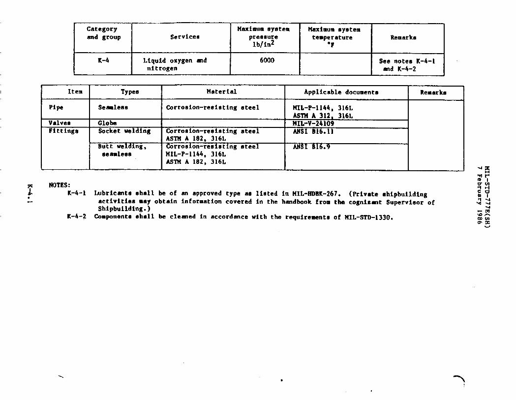
Category Maximum system Maximum systemand group Servicee preeaure temperature Remarka
lb/in2 “F
K-4 Liquid oxygen and 6000 See notes K-4-Initrogen and K-4-2
Item Types Material Applicabledocuments Remarks
Pipe Seaaleaa Corrosion-resistingsteel NIL-P-1144,316LAs7?lA312, 316L
Valves Globe HIL-V-24109Fittings Socketwelding Corroeion-resistingsteel MSI B16.11
ASTM A 182, 316LButt welding, Corro8ion-reeistingoteel ANSI B16.9aeamleas HIL-P-1144,316L
AS’f?lA 182, 316L
~ NOTES:* K-4-1 Lubricantsshall be of an approvedtype as listed in MIL-RDBK-267. (Privateshipbuilding.. activitiesmay obtain informationcovered in the handbookfrom the cognfzmt Supervisorof
Shipbuilding.)K-4-2 Componentsshall be cleaned in accordancewith the requirementsof NIL-STD-1330.
-)
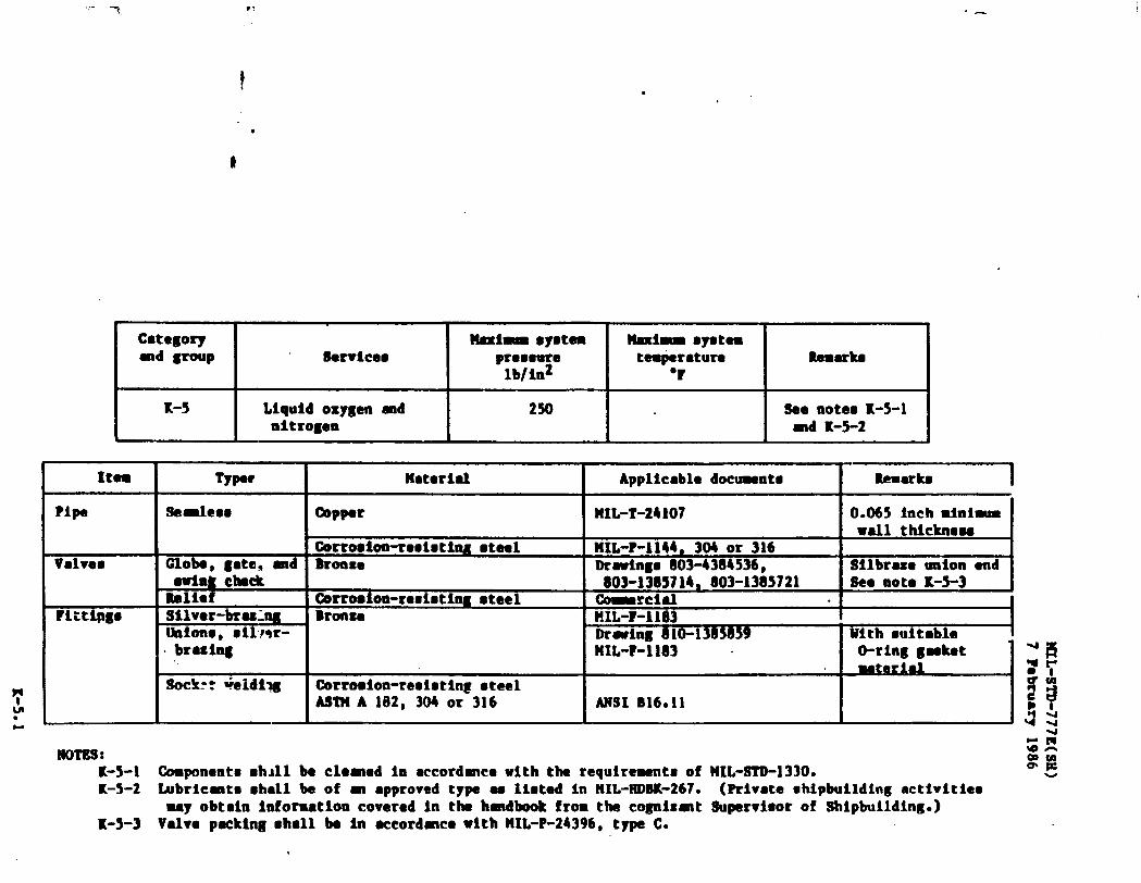
t
,-
.
Category
I I
*IRE $ystem
I
?lmximllmsyete8-d -p flervicea premeure temperature
I
Rem&slb/ln2 ‘r
K-5
I
Liquid oxygen =d
I
250
I I
See note. X-5-1nitrogen md K-5-2
Item
Pipe
Valve9
?ittipgs
no’fus :
Typet
. breshg.,
Wterial I Appllcabledocumnt.
OopperI
MIL-T-241071
Corrocion-resis tlng steel I HIL-P-1144, 304 or 316Brmlxe I Drawinms803-4384536.
803-1385714, 803-1365721@rrosion-resistingsteel -rclal .Bronze MIL-?-li83
Drartng 81O-1N*59?IIL-?-1163 .
(hrroalon-resisting steelASI!HA 102, 3040r 316 I MSI B16.11
K-5-1 Components slull be cleated ie eccordmce with the requirewnto ofK-5-2 tibricmte ●hall be of mI ●pproved type u lioted in MIL-IUJBK-267.
may obtain laforution coveredin the hmdbook from the cogni~mtK-5-3 Valve packing shall be in accordancewith MIL-P-24396,type C.
WL-STD-1330.
.
Remuke 1
====--lWith ●itable {
?
(Private sMpbuilding activitiesSupervisor of Shipbuilding.)
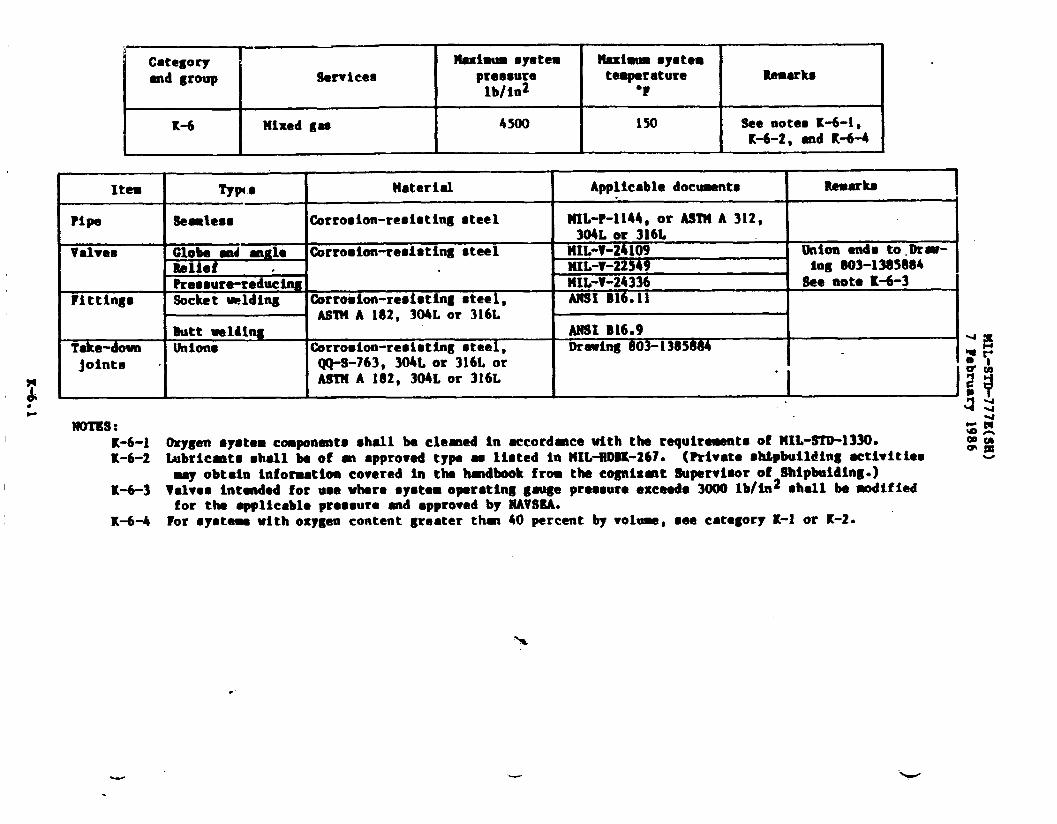
Category Maximsm syetea ?laximum systemmd group !!ervieee preesure temperature Uemerke
lb/in2 b?
K-6 Hixed gae 4500 150 See notes K-6-1,K-6-2, end K-6-4
Ite9
Pipe
Valveo
Fittings
Take-downjoints
mTs!i :
Typt ● Haterial
Se=lese tirroeion-reoicting oteel
GGF_Gii mgle Corroeion-resisting .teelBeliet .Reeeure-reducingSocket -lding Gmroeion-resisting steel,
ASl?tA 182, 304Lor 316LButt -ltlnghim. Qxroeion-reoieting steel,
~S-763, 304Lor 316LorASll(A 182, 304Lor 316L
Applicable documentei
KeDarka
HIL-P-1144, or AS’IMA 312, I304Lor 316L
HIL-V-24109 tklion enh to.l)rar-NIL-v-22549 leg B03-13S5084MIL-V-24336 See note K-6-3ANSI B16.11
ANSt B16.9wmring ~03-1385884
K-6-I Oxygen system cmponents shall be clemed in accord-cc with the requirements of MIL-STD-1330.K-6-2 Ubricmts shell be of m ●pproved type ae lleted in MIL-?IDBK-267.(Privateshipbuildingectiwities
may obtain informatloacovered in the hmdbook from the cognisat Supervisor of Shipbuilding.)K-6-3 Velvee intended for uee where syetem operating gqe preeeure exceede 3000 lb/in2 shall be modified
for the appMcable preeeure and ●ppro~ed by NAVSSA.K-6-4 For ●ysteme with oxygen content greater thm 40 percent by volum, cee category K-1 or K-2.
-.
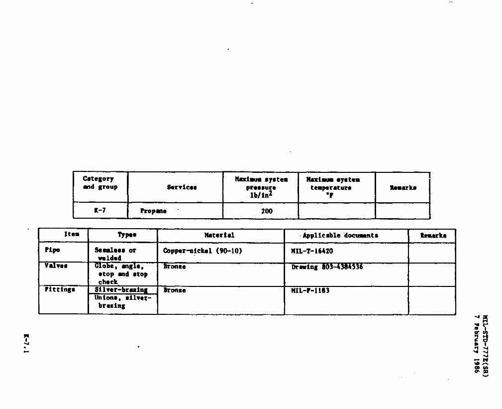
Category H8xImm syotem Hexiam systemmd group Uervicem pressure te9permure Eemrke
lb/in2 ‘?
K-7 Propene “ 200
Item Types Hateriel Applicable documnta
Pipe Sedeom or Copper-oickel (90-10) WL-T-16420umldmd
Valve@ G1obe, engle, lkome Dr-ing 803 -536I ●top md ●top I I
checkFittinge Silver-bresing Bronze MIL-?-1 183
Unions, cilver-
1 brexing
Re9uks
w


Categoryand group
L-1
Servlcee
Cooling, (electronicequipment diesel engine,and so forth) - ethyleneglycol, fresh water solution,dietllled water trmsfer
Maxiaum eyetempreemre
lb/in2
150
Maxim ●yetemte9permm I Remarks I
“F I I150 ISee note L-l-2
I
NOTE:L-l-1 tipper-nickel●hall be ueed for syetemewith s corroeioninhibitoradded to the ●thylene
glycol/wateroolution.L-l-2 Electroniccoolingwater ●ystema which requiredemineralkad water shall use uninhibited
ethylene glycol/water ●olutiono ●nd materials in ●ccordance with cetegoriee C-1 or C-2.

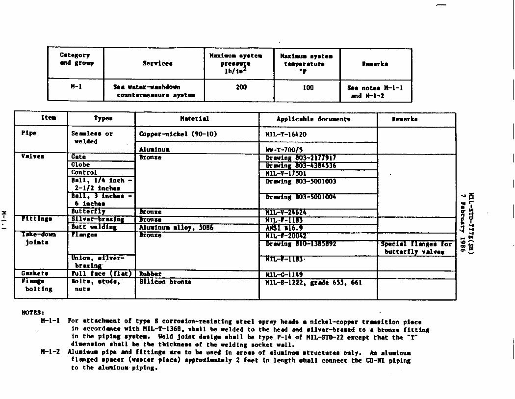
Categorymd group
M-1
Services
!laa water~asMowncountermeasure system
Haximm ayotempressure
lb/in2
200
Uadwm s~etemtemperature Remarks
“F
100 See notes H-I-imd M-1-2
Item Typeo Material Applicable document. Remnrke
Pipe Se-less or @ppar-nickel (90-10) ?tIL-T-16420welded
NOTES:H-1-l For ●ttachment of type S corrosion-reeiating steel spray heads a nickel-copper trmsition piece
in accordmce with HIL-T-1368, shall be welded to the head and silver-brazed to ● bronze fittingin the piping system. Weld joint design shall be type P-14 of HIL-STO-22 except that tlw “T-dlmeneion shall be the thicknessof the welding socketwall.
U-1-2 Aluminum pipe and fittings ●ra to be ueed in ●reas of aluminumstructuresonly. An ●luminumflmged spacer (waeter piece) ●pproxlmtely 2 feet in length shall connectthe CU-NI pipingto the aluminum-piping.


..
.Categoryand group
N-1
Item I l’ypee
Services
Sprinklingsystem(dry)other than foam
Maximumsystem I Maximumsystem Ipressure
I
temperature
I
Remarkslb/in2 “F
, [
175
Material I Applicabledocuments I Remarks I
Pipe Seamless 90-10 copper-ntckel MIL-T-16420Valves Sprinkling Bronze ?lIL-V-17501 See note N-1-l.
control MIL-V-2187 See note N-l-2Fittings Welding 90-10 copper-nickel Drawing 803-1385880
Socket welding 90-10 copper-nickel ANsl BL6.11F1anges Socketwelding 90-10 copper-nickel Drawing810-4715319
Butt welding Drawing810-1385992Unions WeIding 90-10 copper-nickel Drawing803-13&1588k I
IGaskets I Sheet j Synthetic rubber I MIL-G-1149Flange Bolts, studs I Silicon bronze MIL-S-1222, grade 655, 661 1 I
I bolt ingI
and nutsI
NOTES:N-l-1 For automatic or remote manual control.N-l-2 For localmanual control.
w

.
Categoryand group Services
N-2 Magazine sprinklingsystem (wet)
Maximum system
pressurelb/in2
175
Maximumsystemtemperature
IRemarks
“F
I
See Drawing 810-1385958
Item Types 14aterial Applicable documentn Remarks
Pipe Seamless or Copper-nickel, 90-10 MIL-T-16420 Seawater filledwelded
Valves Gate, 2 inches Bronze Drawing 803-1385714 Union endmaximum
Globe, 2 inches Drawing 803-4384536❑aximum
Swing check, 2 Drawing 803-138 5721inches maximum
Gate, 2-1/2 Drawing 803-2177917 Flanged endinches and above
Globe. 2-1/2 Drawing 803-1385623inches and above
Swing check, Drawing 803-13856372-1/2 inchesand above
Sprinkling MIL-V-17501control
Butterfly Bronze MIL-V-24624Fittings Welding 90-10 copper-nickel Drawing 803-1385880
Socket welding AtWI B16.11Flanges Socket welding 90-10 copper-nickel Drawing 810-4715319
Butt welding Drawing 810-1385992Gaskets Sheet Synthetic rubber MIL-G-1149
Cloth, inserted rubber NH-P-1 51Flange Bolts, studs Silicon bronze MIL-s-1222, grade 655, 661
bolting ad nuts
,P”

,—..
Item
Categoryand group Services
Pipe
Fi ttings
Take-downjoints
_Caskets
Flange
bolting
NOTES:
Maximum system Maximum systempres8ure temperature Remarks
lb/in2 “F
1125 See notes O-1-1and O-1-2
Type e I Material I Applicable documents I Remarks
Seamless or Carbon steel MIL-S-22698, type I 775’F maximumwelded ASTM A 106, g rade B
Corrosion-resisting steel ASTM A 376
I 321. or 347 - ! MIL-P-1144 IASTMA 167
Special Corrosion-resisting steelfabricated ASTM A 182, ASTM A 376, Commercial
I MIL-P-1144 I 1Socket welding I Carbon steel, ASTM A 105 or I ANSI B16.11 775°F maximum
I A 181, class 70 IButt welding ] Carbon steel, ASTM A 105 [ MSI B16.9 I
ASTM A 100, grade B orASTM A 181, class 70
Flanges Corro8ion-reetOtingsteel, ANSI B16.5 or speciallyASTMA 182, 321, or 347 fabricatedCast carbon eteel ANSI B16.5 775°FmauimumASTM A 216, grade “P” I I
Sheet Asbestos HiiSpiral wound *tallic MIL-GBolte - stud Alloy steel MIL-S-l~zZ, gxaucNuts MIL-S-1222, grade + I
l-F-46+21032
—
*--- ---’e B16L
0-1-1 Grade 316L corrosion-resisting steel shall not be used where the temperatures may exceed 750”F.o-1-2 Gas turbine exhauet uptake surfacesin directcontactwith hot exhaustgas shall be of nickel-
chromium-molybdenum-columbiumalloy (Ni-Cr-Mo-Cb)in accordancewith ASTM B 443 or ASTM B 444.

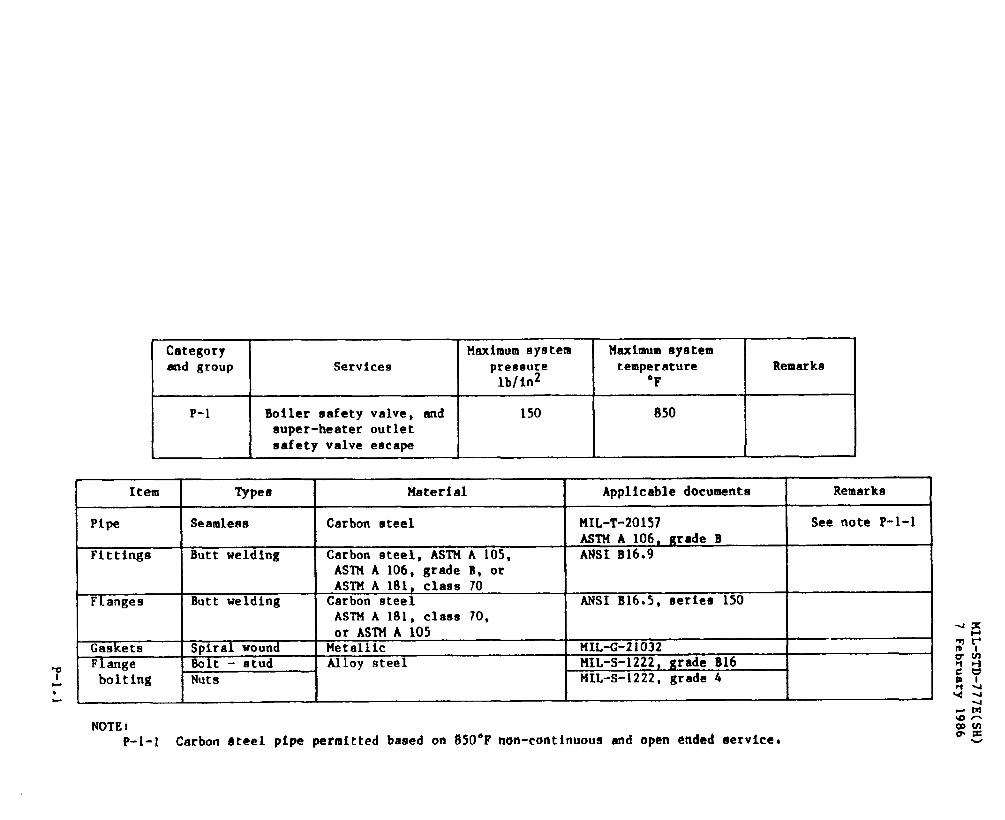
.
Categoryand group
P-1
Item
Pipe
Fittings
Flanges
GasketsFlange
bo 1 t ing
Maximum system Maximum systemServices preeeure temperature Remarks
lb/in2 ‘F
Boiler safety valve, end 150 850super-heater outletsafety valve escape
Typee I Material I Applicable dommenta ] Remarks
Seamletm
Butt welding
Butt welding
Spiral woundBolt - studthltB
Carbon steel MIL-T-20157 See note P-l-1ASTMA 106, Krade B
Carbon steel, ASTM A 105, ANSI B16.9ASTM A 106, grade B, orASTM A 181, class 70
Carbon steel ANSI B16.5, series 150ASTM A 181, class 70, I Ior ASTM A 105
Metallic FfIL-G-21032Alloy steel NIL-S-1222, g rade B16
MIL-s-1222, grade 4
NOTE:P-1-l Carbon steel pipe permitted based on 850°F non-continuousand open ended service.

/-

.-
NOTES:
Item
Pipe
Valves
FLttinga
Mechanicaltake-down
joints
Flangee
Flange
boltingGaskets
CategoryMaximum tlystcm
and group Maximum systemServices pressure temperature Remarks
lb/in2 “F
Q-1 Refrigerant piping 30 inches vacuum minus 85 tO See notes Q-1-lto 300 lb/ln2 pluS 250 and (/-1-2
ITypes Material Applicable documents Remarks
Seamle9s Copper ASTM B 88, hard drawnCopper-nickel MIL-T-16420
Manual Bronze MIL-V-20064Forged brass
Angle reliefMIL-R-16743
Brasa(line)
MIL-R-16743
ControlSilver-brazing
MIL-R-16743 or MIL-R-24085Wrought copper or forged ANSI B16.22
brass See note Q-1-3
Socket and butt &pper-nickel ANSI B16.11 or B16.9weld
O-ring face seal COrroaion-reeisting steel Commercialunions, brazed Copper-nickel O-ring material
Drawing 810-1385889 shall be compati-or weldedDrawing 803-1385948 ble with refrig-
Silver-brazing, Steel erant in System
4-bolt tongueASTM A 105 Flange
and groove BraasBolte, ntuds
CommercialSilicon bronze
AdapterMIL-S-1222, grade 655, 661
and nutsSheet Asbestos HH-P-46
4
w
Q-1-l Copper-nickel piping with welded joints shall be used where practical for locationewhere jointg wouldnot otherwisebe accessiblefor leak detectionand repair.
Q-l-2 The system detilgngauge!reasureis dependentwith refrigerantutilizedR-n, 30 lb/in2; R-12, 225
lb/in2; R-22, 3(30 lb/in , and R-114, 50 ~b/in20Q-1-3 ANSI B16.22 fittingsshall be silver-brazed.

MIL-STD-777E(SH)
7 February 1986d
I
—
wId3vaMfagoawu
—
I I I
LIomQ=cWa
ii”TWsrn
I
d
I
D
II
R-l.]
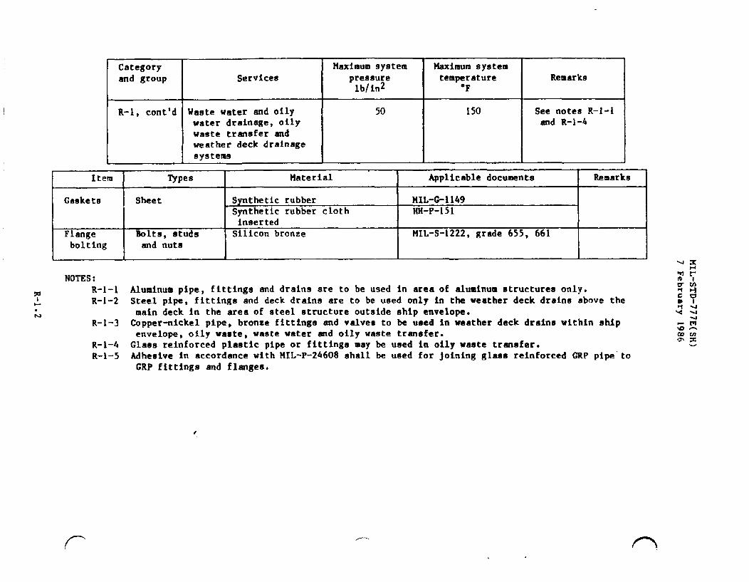
Category Maximum 9ystem Maximum system
and group Services pret3sure temperature Remarkslbfin2 “F
R-1, cent’d Waste water and oily 50 150 See notes R-l-1water drainage, oily and R-1-4waste transfer andweather deck drainagesystems
Item Types Material Applicable documente Remarks
Caskets Sheet Synthetic rubber FIIL-&l149Synthetic rubber cloth NH-P-151inserted
Flange Bolts, studs Silicon bronze MIL-S-1222, grade 655, 661bolting and nuts
NOTES :
R-l-1 Aluminum pipe, fittings and drains are to be used in area of aluminum structures only.R-l-2 Steel pipe, fittings and deck drainn are to be used only in the weather deck drains above the
main deck in the area of steel structure outside ship envelope.R-l-3 Copper-nickel pipe, bronze fittings and valves to be used in weather deck drains within ship
envelope, oily waate, waste water and oily waste transfer.R-l–4 Glaas reinforced plastic pipe or fittings may be used in oily waste tranafer.R-I-5 Adheelve In accordance with MIL-P-24608 shall be used for joining glaaa reinforced GRP pipe’to
GRP flttingg and flangea.
,(--’
f
/----
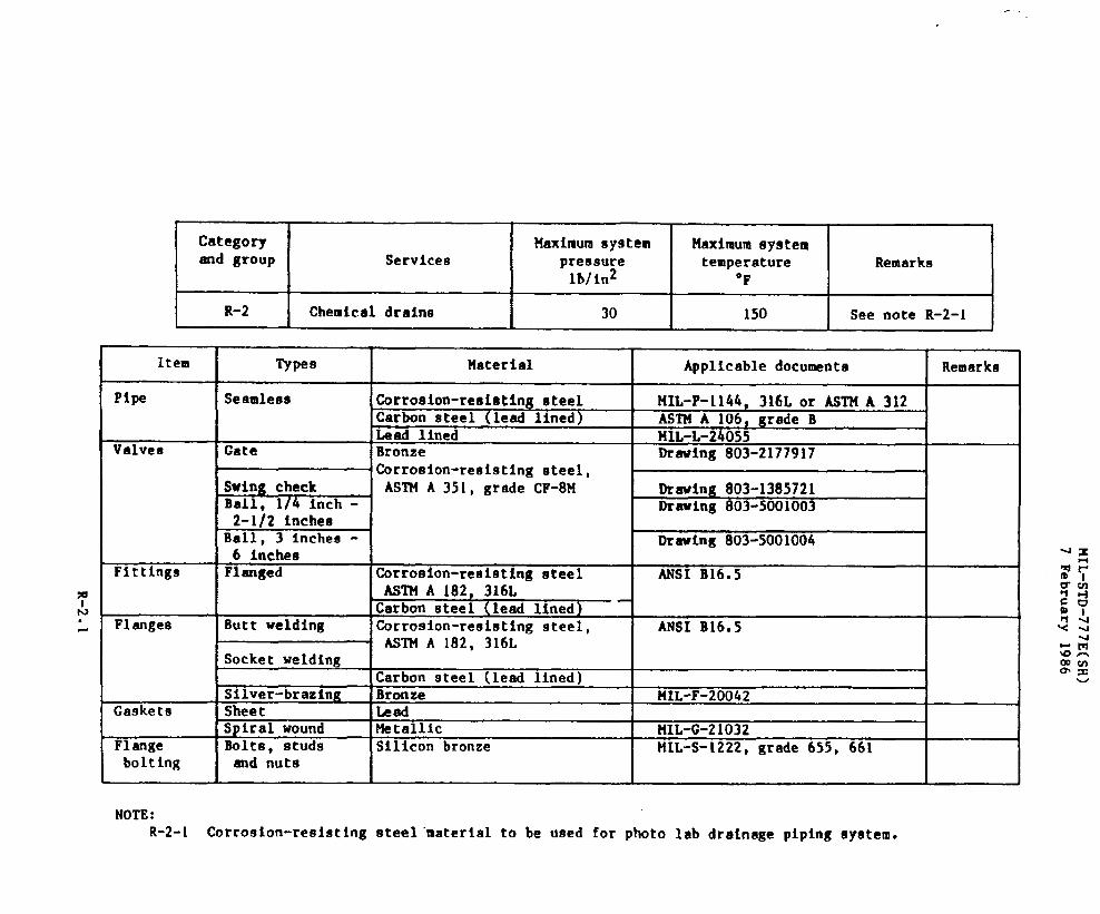
t
Category Maximum sy9tem llnximumSystemand group Services pressure temperature Remarks
lb/in2 “F
I R-2 I Chemical drainsI
30I
150 I See note R-2-1
Item Types l!aterlal Applicable document# Remarks
Pipe Seamless Corrosion-resisting steel MIL-P-1144, 316L or ASTHA 312Carbon steel (lead lined) ASTM A 106, grade BLead lined M2L-L-24055
Valves Gate Bronze Drawing 803-2177917.Corrosion-reeisting steel,
Swing check ASTM A 351, grade CF-8M Drawing 803-1385721Ball, 1/4 inch - Drawing 803-50010032-1/2 inches
Ball, 3 Inchee - Drawing 803-50010046 inches
Fittings Flanged Corroafon-reaieting steel ANSI B16.5AsIM A 182, 316LCarbon steel (lead lined)
Flanges Butt welding Corrosion-resisting 9teel, ANSI B16.5ASTM A 182, 316L
Socket weldingCarbon steel (lead lined)
Silver-brazing Bronze MIL-F-20042Gaskets Sheet Lead
Spiral wound Metallic l’lIL-G-21032Flange Bolts, studg Silicon bronze MIL-S-1222, grade 655, 661bo1ting and nuta
NOTE:R-2-1 Corrosion-resisting steel ’materialto be used for photo lab drainage piping system.
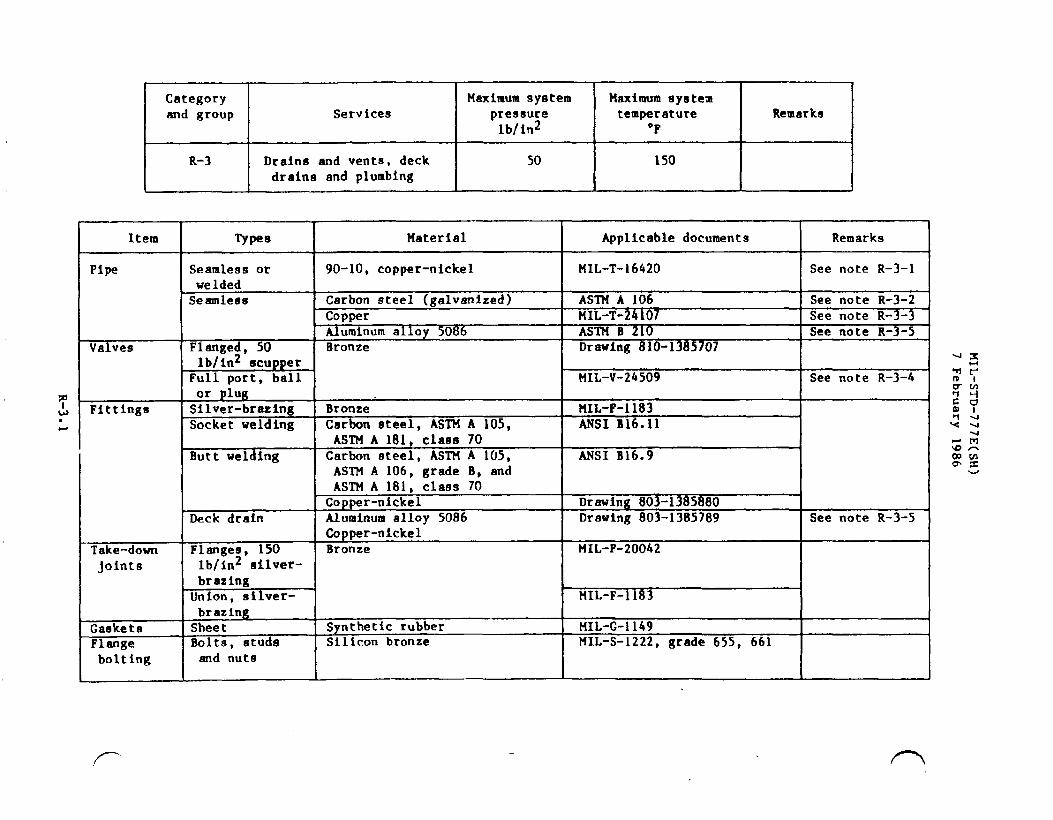
Category Maximum system Maximum systemand group Services pres8ure temperature Remarks
lbfinz “F
R-3 Drains and vents, deck I 50
I
150drains and plumbing I
Item Types ?laterial Applicable documents Remarks
Pipe Seamles9 or 90-10, copper-nickel MIL-T-16420 See note R-3-1weldedSeamless Carbon steel (galvanized) ASTM A 106 See note R-3-2
Copper MIL-T-24107 See note R-3-3Aluminum alloy 5086 ASTM B 210 See note R-3-5
Valves Flanged, 50 Bronze Drawing 810-1385707lb/in2 scupper
Full port, ball MIL-V-24509 See note R-3-4or plug
Fittings Silver-brazing Bronze MIL-F-1183Socket welding Carbon steel, ASTM A 105, ANSI B16.11
ASTM A 181, class 70Butt welding Carbon steel, ASTM A 105, ANSI B16.9
ASTM A 106, grade B, andASTM A 181, class 70
Copper-nickel Drawing 803-1385880Deck drain Aluminum alloy 5086 Drawing 803-1385789 See note R-3-5
Copper-nickelTake-down Flanges, 150 Bronze MIL-F-20042
joints lb/in2 silver-brazing
Union, silver- MIL-F-1183brazing
Gaskets Sheet Synthetic rubber MIL-C-1149
Flange Bolts, studs Silicon bronze MIL-S-1222, grade 655, 661
bolting and nuts

NOTES :R-3-1 Required for water closet and urinal drains, and sea water waete draina, and vent piping subjected
to sea water emersion up to a height of fixture overflow, and sewage treatment plant effluentoverboard discharge.
R-3-2 Steel pipe and fittings ere to be uged only In vent piping above the height of fixture overflowe.R-3-3 Uae for fresh water waste drains and vents up to a height of fixture overflow.
R-3-4 Impregnation of caetinga ae an aid in meeting tightness test is permissible on flanged end valveswhich have no need for application of heat in either ❑anufacture or installation. Impregnationrequirements of MIL-STD-278 are applicable.
R-3-5 Use for fresh water draine in interior aluminum superstructure.R-3-6 Flttfnga used in gravity drainage syetema shall promote smooth flow tntdfacilitate cleaning. Pipe
bends, long radius elbows, sweep ties, laterals and reducing fittinge shall be ueed to the maximumextent practicable. The use of short radius elbows, tees end bushinge shall be avoided.

Category Maxfmum system Maximum system
and group Services pressure temperature Remarkslb/in2 “F
R-4 I Sewage collection, holdingI 50 I 150 I See notes R-4-1and transfer (CHT) and R-4-4
Item
Pipe
Valves
Type8 I tlaterial I Applicable documents Remarks 1
Seamless Copper MIL-T-24107 See note R-4-3Sesmleaa or Copper-nickel, 90-10 MIL-T-16420
weldedSwing check Bronze UIL-V-17547
mk
IFittings
●
“t--===-
Ejoints
Gag ets
sngebolting
NOTES:
wSwing check with❑anual jack-o en device
Full ort3 port, two
Drawing 803-1385637See note R-4-2
MIL-v-24509
positionWelding Copper-nickel Drawing 803-1385880Silver-brazing Bronze MIL-F-1183Flanges Bronze !IIL-F-20042Unio;
\ JMIL-F-1183
Sheets Synthetic rubber MIL-G-1149HH”P-151
Bolts, studs Silicon bronze tiIL-s-1222,grade 655, 661and nuts I I I
R-.$-l Deck discharge connections shall be in accordance with Drawing 803-4444650.R-4-2 Impregnation of castings as an aid in meeting tightness test is permigeible on flanged end valves
which have no need for application of heat in either manufacture or installation. Impregnationrequirements of t41L-STD-278are applicable.
R-4-3 Uae for fresh water collection piping.R-4-4 This category and group shall apply to SOI1 and waste drain piping, waste drain pump and sewage
pump suction and discharge piping, and overflow and vent piping for waste drain tanks.

—. —
MIL-STD-777E(SH)
7 February 1986
,
i’m
S-1.l

.

rCategory Maximum system Maximum systemand group Services pressure temperature
lb/in2 ‘F
T-1 Fixed C02 cofferdam 1900inerting systems
Remarks I
Item Typen Material Applicable documents Remarks
Pipe Seamless Copper MIL-T-24107Carbon steel MIL-T-20157. tme E
Valves Globe and angle Bronze or carbon steel Drawing 803-4384536 400 lb/inZ maximumBall MIL-V-22687Pressure-reducing MIL-v-2961ReliefCylinder
MIL-V-22549Bronze MIL-V-2/15
Fittings Silver-brazing Bronze Drawing 5000-S4823-1385766.Drawing 803-1385942 ‘
Drawing 810-1385863,Drawing 803-1385945
Unions, silver-brazing
Drawing 810-1385859Urawing 803-1385946
Socket welding Carbon steel, ASTM A 105 or MSI B16.11ASTM A 181, class 70
Butt welding Carbon steel, ASTM A 105, ANSI B16.9ASTM A 181, class 70 orASTM A 106, grade B
:askets o-ringZylinders Non-scatterable Steel RR-C-901
NOTE:T-1-l For C02 fire fighting systems see MIL-E-2185, or NIL-E-2186 for specifications and applicable matetfal
and pressure requirements.
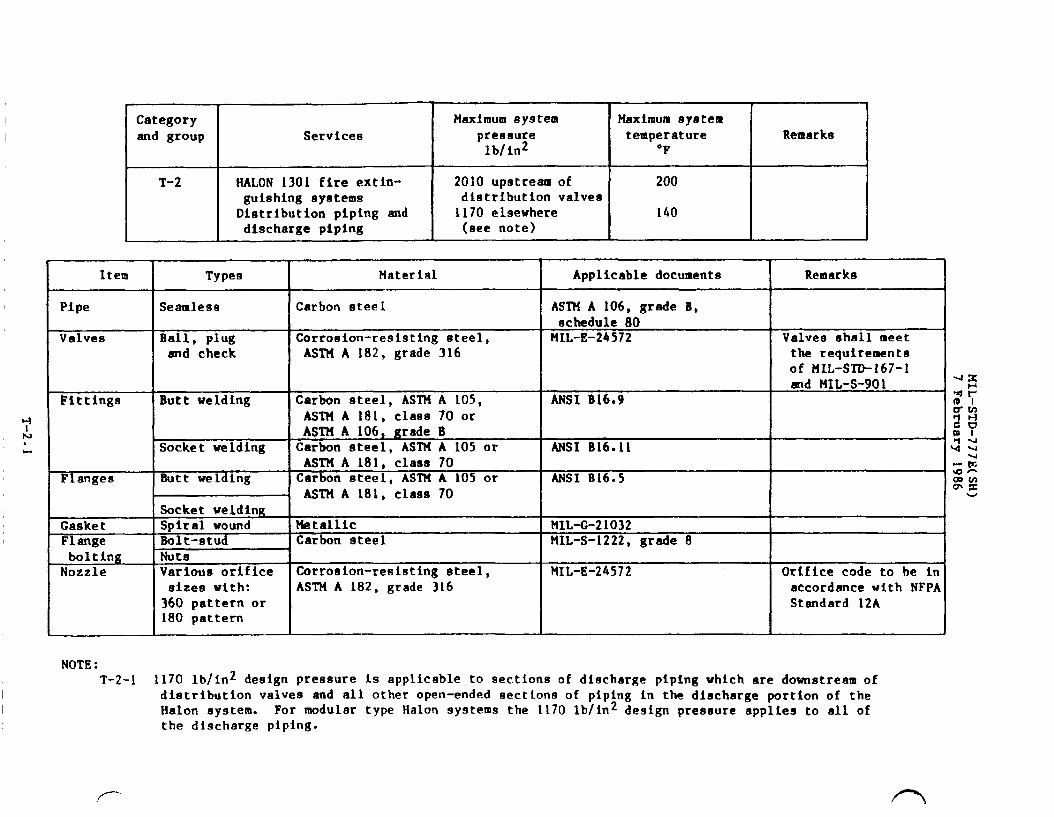
Category Maximum system Maximum eyatem
and group Services pre8t3ure temperature Remarkslb/in2 “F
T-2 HALON 1301 fire extin- 2010 upstream of 200gui8hing systems distribution valveaDistribution piping and 1170 elsewhere 140discharge piping (ace note)
Item Types Material Applicable documents Remarks
Pipe Seamless Carbon steel AS’IMA 106, grade B,schedule 80
Valves Ball, plug Corroeion-resisttng steel, MIL-E-24572 Valves shall ❑eetand check ASTM A 182, grade 316 the requirements
of HIL-STD-167-1
Fittingsmd MIL-S-901
Butt welding Carbon steel, ASTM A 105, ANSI B16.9ASTIIA 181, clase 70 orASTHA 106, grade B
Socket welding Carbon steel, ASTM A 105 or MSI B16.11AsTH A 181, class 70
Flanges Butt welding Carbon steel, ASTM A 105 or MSI B16.5ASTII A 181, class 70
Socket weldingGasket Spiral wound Metallic MIL-G-21032Flange Bolt-stud Carbon steel MIL-S-1222, grade 8bolting Nuts
Nozzle Various orifice Corrouion-resisting steel, MIL-E-24572 Orifice code to he inmizee wtth: ASTN A 182, grade 316 accordance with NFPA360 pattern or Standard 12A180 pattern
NOTE:T-2-1 1170 lb/in2 design pressure is applicable to sections of discharge piping which are downstream of
distribution valves and all other open-ended sections of piping in the discharge portion of theHalon system. For modular type Halon systems the 1170 lb/in2 design pressure applies to all ofthe discharge piping.
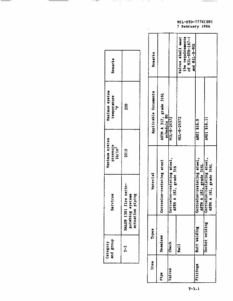
llIL-sTD-777E(sH)7 February 1986
o
0m
I$
T-3.1


Categoryand group Services
u-1 Stripping, fuel
Item
PipeValves
Fittings
Flanges
Gaskets
Flangebolting
150
Types Material
Seamless ISteelGate Carbon steelGlobe, angleand cross
Ball, 1/4 inch -2-1/2 inche8Flanged Carbon steel, ASTM A 181,
ASTM A 105Socket weldingButt weldtng Carbon steel, ASTM A 181,
ASTMA 105 or A?lllA 106,grade B
Butt welding Carbon steel, ASTM A 181,ASTM A 105
Socket weldingSheet Synthetic rubber
Cloth inserted rubberllolts,studs Carbon steeland nuts I
Remarks
See notes U-l-1and U-l-2
Applicable documents I Remarks IASTM A 106, grade AMIL-V-1811OMIL-V-22052Drawings 803-2177525,803-5184193
Drawing 803-5001003
I
ANSI B16.5 Flat face 1
ANSI B16.11MIL-F-20236ANSI B16.9
ANSI B16.5 Flat face
NOTES:U-1-l Gasoline tank stripping shall be in accordance with category H-1.U-l-2 For JP-5 tank stripping, see category I-1.

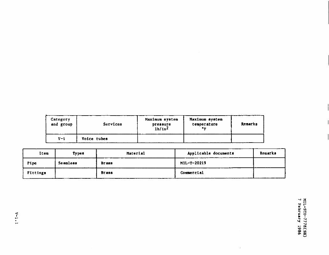
t ?Category Maximum system Maximum systemand group Service9 pressure temperature Remarka
lblin2 “F
v-1 Voice tubes
Item Types Material Applicable documento Remarks
Pipe Seamlee9 Brass MIL-T-20219
Fittings Brass Commercial

(..

,
Category Maximum systemand group Services pre9sure
lb/in2
w-1 I Pneumatic tubesI
Item
Pipe
Maximum systemtemperature I Remarks
“F
Types Material I Remarka I
Seamleas I Brass I IIIL-T-20219 I II 1 I
iSocket sweated I Brass I Commercial I I
G

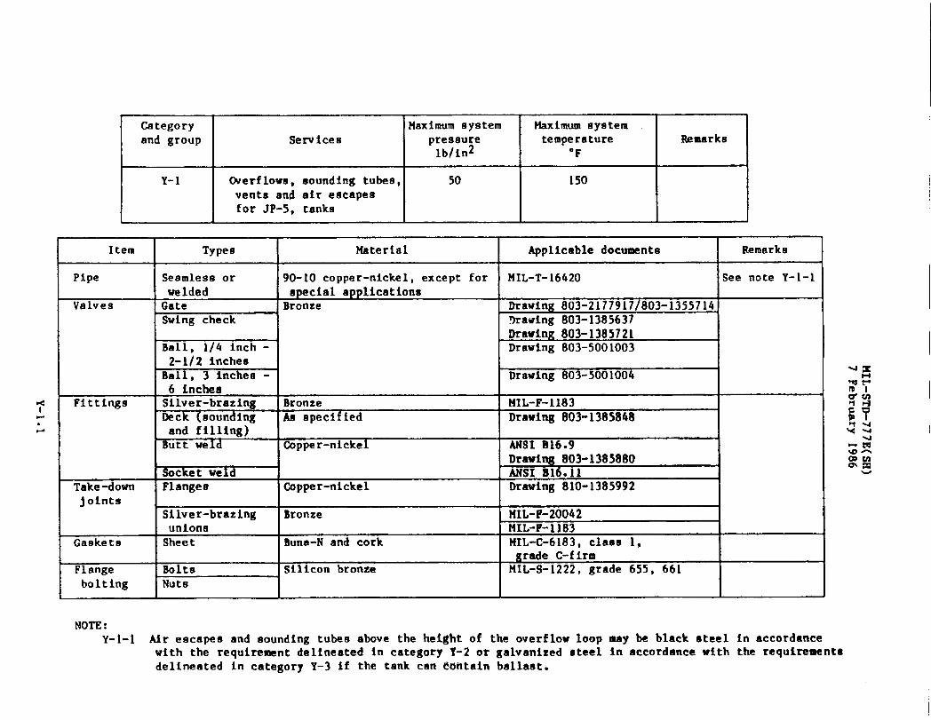
1=.ti
Categoryand group
Y-1
Service8
Overflows, sounding tubes,venta and air escapesfor JP-5, tanks
Maximum system Maximum systempres8ure temperature Remarkslb/in2 “F
50 150
Item Types Material Applicable documents Remarks
Pipe Seamless or 90-10 copper-nickel, except for MIL-T-16420 See note Y-l-1welded special applications
Valves Gate Bronze Drawing 803-2177917/803-1355714Swing check 9rawing 803-1385637
~Drawfng 803-1385721Ball, 1/4 inch - Drawing 803-50010032-li2 Inches
Ball, 3 inchet3- Drawing 803-50010046 inches
Fittings Silver-brazing Bronze FiIL-F-1183Deck (sounding Aa specified Drawing 803-1385848and filling)Butt weld Copper-nickel MSI B16.9
Drawing 803-1385880Socket weld ANSI B16.11
Take-down Flanges Copper-nickel Drawing 810-1385992joints
Silver-brazing Bronze tlIL-F-20042unions t41L-F-1183
Gaskets Sheet Buns-N and cork MIL-C-6183, class 1,grade C-firm
Flange Bolts Silicon bronze MIL-S-1222, grade 655, 661
bo1tIng Nuts
NOTE:Y-1-I Air escapee and sounding tubes above the height of the overflow loop may be black steel in accordance
with the requirement delineated in category 1-2 or galvanized steel in accordance wtth the requirement@delineated in category Y-3 if the tank can Contain ballaat.
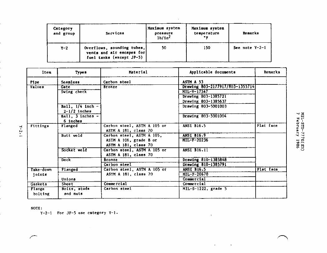
Category Maximum systemand group SerVices preeeure
lb/ln2
Y-2 Overflows, sounding tubes, 50vents and air escapes forfuel tanks (except JP-5)
Maximum systemtemperature I Remarks
*
Item Types Material Applicable documents Remarks
Pipe Seamless Carbon steel As’m& 53Valves Gate Bronze Drawing 803-2177917/803-1355714
Swing check MIL-V-17547Drawing 803-1385721Drawing 803-1385637
Ball, 1/4 inch - Drawing 803-50010032-1/2 inches
Ball, 3 inches - Drawing 803-50010046 inches
Fittings Flanged Carbon steel, ASTN A 105 or ANSI B16.5 Flat faceASTM A 181, class 70
Butt weld Carbon steel, ASTM A 105, ANSI B16.9ASTIIA 106, grade B or MIL-F-20236ASTM A 181, class 70
Socket weld Carbon steel, ASTM A 105 or ANSI B16011ASTM A 181, claes 70
Deck Bronze Drawing 810-1385848Carbon steel Drawing 810-1385791
Take-down Flanged Carbon steel, ASTM A 105 or ANSI B16.5 Flat facejoints ASTM A 181, class 70 MIL-F-20670
Unions CcmmarcialGaskets Sheet Commercial COnmtercialFlange Bolts, studs Carbon eteel MIL-S-1222, grade 5bolting and nuts
NOTE:Y-2-1 For JP-5 use category Y-1.

Category Maximum system Maximum systemand group Services pressure temperature Remarks
lb/in2 ‘F
Y-3 Overflows, sounding tubeg, 50 150 See note Y-3-1vents and air escapesfor other than fueltanks (freeh water(except potable) clean
ballast, voids, etc.)
Item
PipeValvee
Fittings
Take-downjoints
FGas etaFlangebolting
Types I Material
Seamleas Carbon steel, galvanizedGate BronzeSwing check
Ball, 1/4 inch -2-1/2 inches
Ball, 3 inches -6 inches
Flanged Carbon steel, galvanizedASTM A 105 or ASTM A 181,class 70
Butt Garbon steel, ASTM A 105,ASTM A 106, grade B or
I ASlt4A 181, class 70Socket weld lCarbon steel, ASTM A 105 or
ASTM A 181, class 70Deck Bronze
Carbon steelFlanged Carbon steel, galvanized
ASTM A 105 or
I ASTH A 181, class 70UnionsSheet CommercialBolts, etude Carbon steeland nut6 I
Applicable documents I Remarks
ASTM A 53
Drawing 803-5001004
ANSI B16.5 Flat face
MS1 B16.9HIL-F-20236
ANSI B16.11I
uLaw&ta6 VAV LAUJ<
Draw@ --- .....ANSI Blo.MIL-F-206,.
n.9-4 .“ Qln_llnc 948
3 UIU-13U>)91..
5 Flat face;7n
I
CommercialComercialMIL-S-1222, grade 5
Y-3-1 For potable water use category c-2.

!!!EEL-’ce’Maximum system Maximum system
pressure temperature Remarkslb/in2 ‘F
Y-4 I Vents, reduction gearI
5I
AmbientI
Item I Typm Material I Applicable documents I Remarks
I Pipe ISeamless orweldr>
l Copper-nickel, 90-10 I 141L-T-16620 I1
1Fittings Silver-brazing BronzfFlanges Silver-brazing BronzeGaakets Sheet Commel
ea I# t41L-F-1183! HIL-F-20042:cial Commercial
! Flange ] Bolts, studs I Silicon bronze HIL-S-1222, grade 655, 661I bolting I ad nuta I I I
l-.
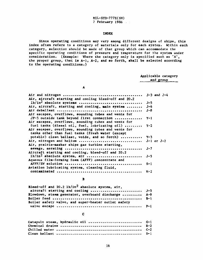
MIL-STD-777E( SH)7 February 1986
INDEX
Since operating conditions may vary among different designs of ships, thisindex often refers to a category of materials only for each system. Within eachcategory, selection should be made of that group which can accommodate thespecific operating conditions of pressure and temperature for the system underconsideration. (Example: Where the category only is specified such as “’A-,the proper group, that is A-1, A-2, and so forth, shall be selected accordingto the operating conditions.)
Applicable categoryand group
A
Air and nitrogen ........................................Mr, aircraft starting and cooling bleed-off and 20.2lb/in2 absolute systems ................................
Air, aircraft, starting and cooling, main system ........Mr deballast ...........................................Air escapes, overflows, sounding tubes and vents forJP-5 outside tank beyond first connection ..............
Air escapes, overflows, sounding tubes and vents forfuel tanks (diesel oil, fuel, lubricating oil) .........
tir escapes, overflows, sounding tubes and vents fortanks other than fuel tanks (fresh water (exceptpotable) clean ballast, voids, and so forth) ...........
tir, nitrogen and helium ................................Air, prairie-masker ships gas turbine starting,sewage, aerating .......................................
Mrcraft starting and cooling, bleed-off and 20.2lb/in2 absolute system, air ............................
Aqueous film-forming foam (AFFF) concentrate andAFFF/SWsolutlon .......................................
Aviation lubricating system, cleaning fluid,contaminated ...........................................
J-3 and J-4
J-5J-6J-8
Y-I
Y-2
Y-3J-1 or J-2
J-7
J-5
s-1
H-2
B
Bleed-off and 20.2 lb/in2 absolute system, air,aircraft starting and cooling .......................... J-5
Blowdown, steam generator, overboard discharge .......... A-9Boiler feed ............................................. B-1Boiler safety valve, and super-heater outlet safetyvalve escape ........................................... P-1
c
Catapult steam, hydraulic oil ........................... G-1Chemical drains ......................................... R-2Chilled water ........................................... C-2Clean ballast ........................................... D-1
16
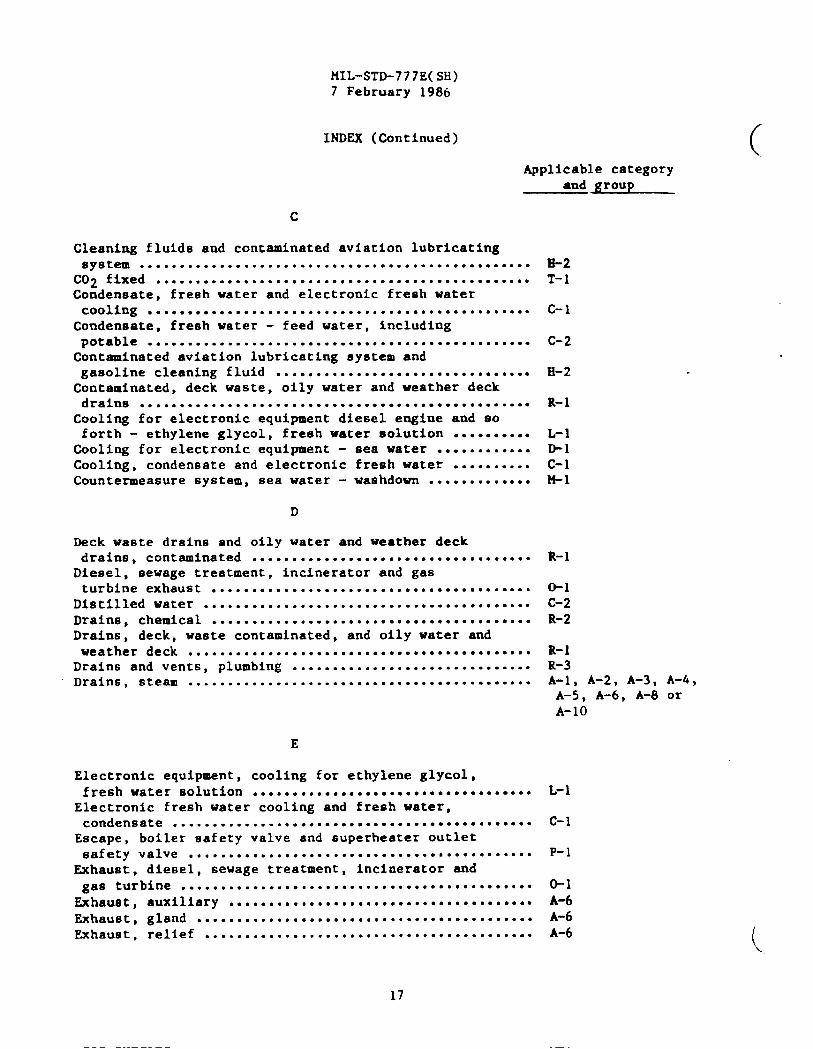
MIL-STD-777E(SH)7 February 1986
INDEX (Continued)
Applicable categoryand group
c
Cleaning fluids and contaminated aviation lubricatingByStem ● ..*..****..*. .*...***..*..* ..............● .**...
C02 fixed ● ................● ....● ........● ..● ● ● .● ● ● .● ..● 0Condensate, freeh water and electronic fresh watercooling ................................................
Condensate, fresh water - feed water, includingpotable ................................................
Contaminated aviation lubricating system andgasoline cleaning fluid ..● ...● .....● ● ...● O.● .● ..● ● .● ..0Contaminated, deck waste, oily water and weather deckdrains .................................................
Cooling for electronic equipment diesel engine and soforth - ethylene glycol, fresh water solution ..........
Cooling for electronic equipment -Cooling, condensate and electronicCountermeasure system, sea water -
D
seawater ............freshwater ..........washdown .............
Deck waste drains and oily water and weather deckdrains, contaminated ...................................
Dieeel, sewage treatment, incinerator and gasturbine exhaust ........................................
Distilled water .........................................Drains, chemical .........................*...*..*..**...Drains, deck, waste contaminated, and oily water andweather deck ..........................*. ...............
Drainfi and vents, plumbing ..............................Drains, steam ...........................................
E
Electronic equipment, cooling for ethylene glycol,freshwater solution ...................................
Electronic fresh water cooling and fresh water,condensate .............................................
Escape, boiler safety valve and superheater outletsafety valve ...........................................
Exhaust, diesel, sewage treatment, incinerator and
gas turbine ............... ● .......,......● ..● ........● .
Exhaust, auxiliary ......................................Exhaust, gland ..........................................Exhaust, relief ................● .....● ● ..● .● ● ...........
H-2T-1
c-l
c-2
H-2
R-1
L-1D-1c-1M-1
R-1
*1c-2R-2
R-1R-3A-1, A-2, A-3, A-4,A-5, A-6, A-8 orA-10
c-‘
P-
*IA-6A-6A-6
17

iffL-s*777E(sH)7 February 1986
INDEx (Gentinued )
F
Feed boiler .............................................Feed systems propulsion plant saturated .................Feed water - fresh water and condensate, includingpotable ................................................
Filling transfer and tank stripping, JP-5 fuelaenice ................................................
Film-forming foam (AFFF) concentrate and AFFF/SWeolution, aqueous ......................................
Fixed C02, cofferdam inerting systems ...................Fresh water, condensate and electronic fresh watercooling ....o.........g.................................
Fresh water, chilled water, feed water and condensate,including potable ......................................
Fuel and tank stripping, JP-5 ..**..● ...● ...● ..● ........●
Fuel ....................................................Fuel, gas turbine powered ships .........................Fuel, stripping .....● .....................● .......● .● ...
G
Gas, mtxed ..............................................Gaseous oxygen ..........................................Gaseous oxygen, outside hull ............................Gasoline ................................................Gas turbine bleed air system ............................Gas turbine and diesel, sewage treatment, incinerator,exhaust ................................................
Gauge piping ............................................Gland, exhaust ...● O.............● ....● ..................EALON 1301 (fire extinguishing system) ..................Helium, air and nitrogen ................................Mull, gaseous inside; oxygen ...........*... .............Hull, gaseous outside; oxygen ...........................
Applicable categoryand group
Hydraulic
Hydraulic
oil - other than steam catapult ...............
oil, steam catapult ...........................
I
Inside hull, gaseous oxygen .............................
J
JP-5 fuel service, filling transfer or tank stripping ...
B-1B-2
c-2
I-1,
sT
c-1
c-2I-1,E-1,E-4u
K-6K-3K-1H-1J-9
o-1Dwg .A-6T-2
u-1
u-1E-2 and E-3
804-1385850
J-1 or J-2K-2K-1*3, G4, G5,or G-7
G-1 or G-2
K-2
I-1, u-1
G-6 ,
18
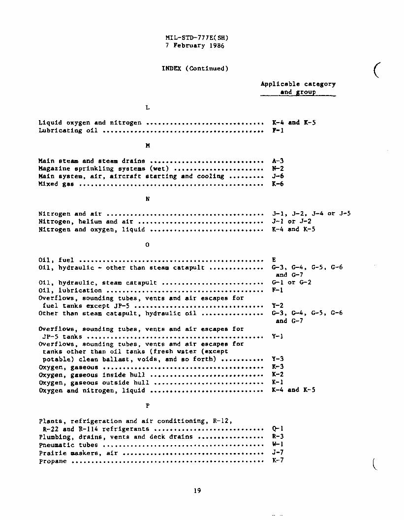
MIL-STD-777E(SH)7 February 1986
INDEX (Continued)
Applicable category
and group
L
Liquid oxygen and nitrogen .............................. K-4 and K-5Lubricating oil ......................................... F-1
M
14ain eteam and eteamdralna ............................. A-3Magazine sprinkling systems (wet) ....................... N-2Main system, air, alrcrafc starting and cooling ......... J-6Mixed gas ............................................... K-6
N
Nitrogen and air ........................................ J-1, J-2, J-k or J-5Nitrogen, helium and air ................................ J-1 or J-2Nitrogen and oxygen, liquid ............................. K-4 and K-5
o
Oil, fuel ...............................................Oil, hydraulic - other than steam catapult ..............
Oil, hydraulic, steam catapult ..........................Oil, lubrication ........................................Overflows, sounding tubes, vents and air escapes forfuel tanks except JP-S .................................
Other than steam catapult, hydraulic oil ................
Overflows, sounding tubes, vente and air escapes forJP-5 tanks .............................................Overflows, sound%ng tubes, vents and air escapee fortanks other th8n oil tanks (fresh water (exceptpotable) clean ballast, voids, and so forth) •....~...~.Oxygen, gaseous .........................................Oxygen, gaseous inside hull ......● .....● .............● SSOxygen, gaseous outside hull ● .......● ● .● ...● ............Oxygen and nitrogen, liquid .............................
P
EG-3, G-4, G-5, G-6and G-7
G-1 or G-2F-1
Y-2G3, G-4, G-5, G-6and G-7
Y-1
Y-3K-3K-2K-lK-4 and K-5
Plants, refrigeration and air conditioning, R-12,R-22 and R-114 refrigerants ............................ *1
Plumbing, drains, vents and deck drains ................. R-3pneumatic tubes ......................................... U-1
Prairie maskers, air .................................... J-7Propane ................................................. K-7
19

MIL-STD-777E( SH)7 February 1986
INDEX (Continued)
Applicable categoryand group
R
Reduction gear, vents ...................................Refrigeration and air conditioning plant R-12 and R-22refrigerants .OO......O...O ...ee.g*g.o.ee ● oe.........oe.
Relief, exhaust .........................................
s
Safety valve, boiler, escape ............................Sea water, ballast and oily waste .......................Sea water missile injection eystem between freshwater accumulating tank and nozzles ....................Sea water, washdown, countermeasure system ..............Sewage collection, holding and transfer system (CHT) ....Sounding tubes, overflows, vents and air escapes forJP-5 tanks .............................................
Sounding tubes, overflows , vents and air escapes forfuel tanks (except JP-5) .● ...*.. ● ...*...● ...........● . .
Sounding tubes, overflows, vents and air escapes fortanks other than fuel tanks (fresh water (exceptpotable) clean ballast, voids, and so forth) ...........
Sprinkling system (dry) other than foam .................Sprinkling system (wet) magazine ........................Starting and cooling, air, aircraft .....................Steam ...................................................Steam and steam drains ..................................
Cteam catapult, hydraulic Oil . . . . . . . . . . . . . . . . . . . . ● . . ● . . ●.Steam system overboard discharge, steam generatorblowdown ...............................................
Strlpplng, JP-5 .........................................Stripping, fuel .........................................Superheater outlet safety valve escape ..................System (dry), sprinkling other than foam ................System (wet), magazine sprinkling .......................Systems, feed ...........................................
T
Tank stripping and JP-5 fuel service, f5111ng
tra~sfer ...............................................Tube, voice .............................................Tubes, pneumatic ........................................
Y-4
Q-1A-6
P-1D-1 or D-3
=2?4-1R-4
Y-l
Y-2
Y-3N-1N-2J-6A-7A-1, A-2, A-3, A-4,A-5, A-6, A-8, andA-ICI
*1 and G-2
A-9I-1u-1P-1N-1N-2B-1
I-1, u-1v-1w-1
20

MIL-STD-777E( Sl!i)7 February 1986
INDEX (Continued)
Applicable category-d group
v
Valve, boiler Bafety and superheaters outlet eafetyescape ..............● ...o.a....a.g,...Og.O.~OOOO .....OO P-1
Vents and drains, deck drains and plumbing .............. R-3
Vents. reduction gear ................................... Y-4Vents, overflows, sounding tubes, and air escapes forJP-5 tanks ............................................. Y-1
Vents, overflows, sounding tubes, and air escapes foroil tanks except JP-5 ...........*..........**..*. ...... Y-2
Vents, overflows, sounding tubes, and air escapes forother than oil tanks (fresh water (except potable)clean ballast, voids, and so forth) ...................* Y-3
Voice tubes ............................................. v-1
id
Washdown - sea water, countermeasure system .............Water, fresh, condensate and electronic fresh watercooling (chilled) ...● ..● ..**................● ● ...*.....
Water, fresh, feed, condensate, including potable .......
M-1
c-1c-2 (
21

W$TRUCTI ONS: in ● amtinuing effort to make our stmdsrdsation documents hettar, the DoD Proddes tbb foma forw inmrbmittiagcormmenti sad SUUUtioru for iraprovemenk.AllusenofmiAitarystandardisation documenti sre invited to prmide
~SU. ~ form OMY ~ ~~cb~. fol~ *CU the ~na %!!*, hp.d ~OW the Ioow + (DO NOT STAPL19, endmdkd. In bIak 6, be M specific M poedbh shout puthlsr problem are.w such m wording which required Merpmtstii, wu.-tao rigid, mstricthe, Iw, ambiguous,or - incompdblt, and etse Proposed wordingch4ea which would ahviate thepoblems. En@r in biosk 6 Uiy --k mot r’let’d to ~ specik parqrsph Of the document. If block 7 is filled out, au
Aoowbedgcnmit will be mdhd to YOU with SO deYS b lot YOU know thet your commeo tewemrec&ed midugb e&g
ddewd.
NOIE: ‘RIU form msy not be IMUJ to request COpim Of documents, nor to request weivers, dwistiq or clulficetkm ofqodfiation requirement on eument contmcti. Commente submitted on thu form do not ccm$titute or imply ●+horixation
to mhe any posth of the refemriced document(t) or to unend contractual requirement.
(Fold AIons tAh UM)
(Fold along thk 1(-)
DEPARTMENT OF THE NAVY
!2MMANDERNAVAL SEA SYSTEMS COMMAND (SEA 55Z3 )
D WARTMENT OF THE NAVY 111111FI“V3H1NGTON , DC 20362 UNITED STATES
—OWICIAL ●U&ME=?% WALTY FOR ●RIVATE USE S- [ BUSINESS REPLY MAIL I
1 FIRST CLASS PERMIT NO 12503 wASHINGTON D Ci
PO~AGE WILL BE PAID BY THE DEPARTMENT OF THE NAVY
COMMANDER
NAVAL SEA SYSTEMS COMMAND (SEA 5523)DEPARTKENT OF THE NAVYWASHINGTON , DC 20362
I
I
I
I1
II
S’TANOARDIUTION DOCUMEm IMPROVEMENT PROPOSAL(&c lnstntdnu - RePUU SideJ I
, 00 CUMEMT NUM_tR 2. OOCUMEN7 TITLE
MIL-STD-777E(SH)Schedu Le Of Piping, Valves, Fittin$ls, And
Associated Pipinq Components For Naval Surface Sh~psL MAME O@W#BM$TTINOOnOAN1~T1- 4.tVUOSOR@ANUATIOM f-omoJ
•1 vcumm
1
. ●ROSLEM AnEAs
, REMARKS
‘DO FORM●2 MAR 1426 ●REvIO- EDITION U O@EOLEIE.
Top Related