


Languages
Pages
Legal


~,,-ml=%15 FEB 1994
SUPERSEDINGhWL-STD-lBB-125
26 JUN 1990
MILITARY STANDARD
HIGH-ALTITUDE ELECTROMAGNETIC PULSE (HEMP) PROTECTIONFOR GROUND-BASED &l FACILITIES PERFORMING CRITICAL,
TIME-URGENT MISSIONS
VOLUME IFIXED FACILITIES
(METRIC)
AMSC NIA
DISTRI UTION STATEMENT ~.B
AREA TCSS
Approved for public releese; distribution is unlimited.
Downloaded from http://www.everyspec.com

DEPARTMENT OF DEFENSEWashington DC 20301
HIGH-ALTfTUDE ELECTROMAGNEflC PULSE (HEMP) PROTECflONFOR FIXED GROUND-BASED C’f FACUJTIES PERFORMING CRMCAL,
TIME-URGENT MISSfONS
1. This military standard is approved and mandato~ for use by all departmentsand agencies of the Department of Defense in accordance with Department ofDefensa Directive 5000.2, 23 February. 1991.
2. Beneficial comments (recommendations, additions, deletions) and any pertinent
data which may be of use in improving this document should be addressed to: HQAFC4A/TNAS, 607 Pierce Street, Room 303, Scott AFB IL 62225-5421 by usingthe Standardization Document Improvement Proposal (DD Form 1426) appearing atthe end of this document or by letter.
ifii
Downloaded from http://www.everyspec.com
MlL-STD-l 88-1 25A
1.. Originally, Military Standard 188 (MIL-STD-188) covered technical standards fortactical and long-haul communications, but later evolved through revisions (MIL-STD-1 88A, Ml L-STD-l 88B) into a document applicable to tactical communicationsonly (MIL-STD-188C).
2. The Defense Information Systems Agency (DISA) published DISA circulars(DISAC) promulgating standards and engineering criteria applicable to the long-haulDefense Communication System and to the technical support of the NationalMilitary Command System.
3. As a rasult of a Joint Chiefs of Staff action, standards for all militarycommunications are now being published in a MIL-STD-188 series of documents.The Ml L-STD-l 88 series is subdivided into a MlL-STD-l 88-100 series, coveringcommon standards for tactical and long-haul communications; a Ml L-STD-l 88-200series, covering standards for tactical communications only; and a MlL-STD-188-300 series, covering standards for long-haul communications only. Emphasis isbeing placed on developing common standards for tactical and long-haulcommunications published in the MIL-STD-188-1OO serias.
4. This document contains technical standards and design objectives for High-Altitude Electromagnetic Pulsa (HEMP) protection of ground-based facilities whichare nodas in a HEMP-hardened natwork for performing critical and time-urgentcommand, control, communications, computer, and intelligence (&f) missions. Therequirements are stringent in order to avoid both damage and functional upsetswhich prevent mission accomplishment within operationally prescribed timelines.The standards apply uniformally to all facilities in tha end-to-end chain, sincedisruption of a single noda may result in network failure.
5. This Voluma I of MIL-STD-188-125A addresses HEMP hardaning for fixedground-based facilities which perform critical, time-urgent C41missions.
6. Use of the standsrd for HEMP protection of other ground-base communications-electronics facilities that require hardening is encouraged to tha extent permittad bycost constraints.
7. Performance, acceptance, and verification requirements are contained in thebody of tha standard. HEMP-unique acceptance and verification test techniquesare temporarily included as appendices A, 8, and C.
...Ill
Downloaded from http://www.everyspec.com

MlL-STD-l 88-1 25A
8. Implementation of MIL-STD-188-125A, Volume 1 is supported by MIL-HDBK-423 “High-Altitude Electromagnetic Pulse (HEMP) Protection for Fixed andTransportable Ground-Based Facilities, Volume 1, Fixed Facilities.” The handbookalso includes planning, management, logistics, and data requirements for critical,time-urgent fixed, ground-based facilities.
ivlv
Downloaded from http://www.everyspec.com

MlL-STD-l 88-1 25ATABLE OF CONTENTS
PARAGRAPH PAGE #
1.
1.1
1.21.31.4
2.2.12.1.12.1.22.22.32.4
3.3.13.23.33.3.13.3.23.3.33.3.43.3.53.3.63.3.73.3.83.3.93.3.103.3.113.3.123.3.133.3.143.3.153.3.163.3.173.3.183.3.193.3.20
SCOPE . . . . . . . . . . . . . . . . . . . . . . . . . . . . . . . . . . . . . . . . .Purpose . . . . . . . . . . . . . . . . . . . . . . . . . . . . . . . . . . . . . . .Scope . . . . . . . . . . . . . . . . . . . . . . . . . . . . . . . . . . . . . . . . .Applications . . . . . . . . . . . . . . . . . . . . . . . . . . . . . . . . . . . . .Objectives . . . . . . . . . . . . . . . . . . . . . . . . . . . . . . . . . . . . . .
REFERENCED DOCUMEWS . . . . . . . . . . . . . . . . . . . . . . . . . .Government documents . . . . . . . . . . . . . . . . . . . . . . . . . . . . .Specifications,standards,andhandbooks . . . . . . . . . . . . . . . . .Other Government documents. drawings, and publications . . . . .Otherpublications . . . . . . . . . . . . . . . . . . . . . . . . . . . . . . . .Source ofdocuments . . . . . . . . . . . . . . . . . . . . . . . . . . . . . .Order of precedence . . . . . . . . . . . . . . . . . . . . . . . . . . . . . . .
1
1
11
1
2223444
DEFINfllONS . . . . . . . . . . . . . . . . . . . . . . . . . . . . . . . . . . . . 5Acronyms usadin thisstandard . . . . . . . . . . . . . . . . . . . . . . . 5Sources for definitions . . . . . . . . . . . . . . . . . . . . . . . . . . . . . 6Additional definitions . . . . . . . . . . . . . . . . . . . . . . . . . . . . . . 7Aperture POE HEMPshield surface . . . . . . . . . . . . . . . . . . . . . 7Conductive POE . . . . . . . . . . . . . . . . . . . . . . . . . . . . . . . . . . 7Continuous Wave immersion. . . . . . . . . . . . . . . . . . . . . . . . . . 7Corrective maintenance . . . . . . . . . . . . . . . . . . . . . . . . . . . . . 7Electromagnetic barrier . . . . . . . . . . . . . . . . . . . . . . . . . . . . . 7Electromagnetic stress . . . . . . . . . . . . . . . . . . . . . . . . . . . . . 7Facility HEMPshield . . . . . . . . . . . . . . . . . . . . . . . . . . . . . . . 7HEMP accaptancetast . . . . . . . . . . . . . . . . . . . . . . . . . . . . . 7HEMP hardness . . . . . . . . . . . . . . . . . . . . . . . . . . . . . . . . . . 8HEMP Hardness Assurance . . . . . . . . . . . . . . . . . . . . . . . . . . 8HEMP Hardness Critical ltem(HCl) . . . . . . . . . . . . . . . . . . . . . 8HEMP Hardness Critical proces-s (HCp) . . . . . . . . . . . . . . . . . . 8Hardness Maintenance (HM) . . . . . . . . . . . . . . . . . . . . . . . . . 8HEMP Hardness Maintenance and Hardness Surveillance (HM/HS) 8HEMP protection subsystem . . . . . . . . . . . . . . . . . . . . . . . . . . 8Hardness Surveillance (HS)... . . . . . . . . . . . . . . . . . . . . . . . . 9Low-risk HEMP hardening. . . . . . . . . . . . . . . . . . . . . . . . . . . 9Main barrier . . . . . . . . . . . . . . . . . . . . . . . . . . . . . . . . . . . . . 9Main barrier protective device . . . . . . . . . . . . . . . . . . . . . . . . 9Mission-Critical Systems (MCS) . . . . . . . . . . . . . . . . . . . . . . . 9
vi
Downloaded from http://www.everyspec.com

MlL-STD-l 88-1 25ATABLE OF CONTENTS
PARAGRAPI-I In!2.Ed
3.3.213.3.223.3.233.3.243.3.253.3.263.3.273.3.283.3.293.3.303.3.313.3.323.3.333.3.343.3.353.3.363.3.373.3.383.3.39
4.4.14.1.14.1.24.24.34.3.14.3.24.3.34.3.3.14.3.3.24.3.3.34.3.44.44.4.14.4.24.4.34.54.5.1
Norton Source . . . . . . . . . . . . . . . . . . . . . . . . . . . . . . . . . . . ..9Penetrating conductor . . . . . . . . . . . . . . . . . . . . . . . . . . . . . . 9Penetration entry Erie..... . . . . . . . . . . . . . . . . . . . . . . . . . 9Point-of-Entry (POE) . . . . . . . . . . . . . . . . . . . . . . . . . . . . . . . 9POE protective device or POE treatment . . . . . . . . . . . . . . . . . 10Praventiva maintananca . . . . . . . . . . . . . . . . . . . . . . . . . . . . 10Primary special protective device . . . . . . . . . . . . . . . . . . . . . . 10Protactad volume . . . . . . . . . . . . . . . . . . . . . . . . . . . . . . . . 10Pulsed current injection (Pal) . . . . . . . . . . . . . . . . . . . . . . . . 10Residual lntarnalstrass . . . . . . . . . . . . . . . . . . . . . . . . . . . ..10Ratrofit HEMPhardening . . . . . . . . . . . . . . . . . . . . . . . . . . ..10Secondary special protective device . . . . . . . . . . . . . . . . . . . . 11Shleldad enclosura teak detaction system (SELDS) . . . . . . . . . . . 11Special protactive measures . . . . . . . . . . . . . . . . . . . . . . . ...11Special protective volume . . . . . . . . . . . . . . . . . . . . . . . . ...11Verification testing . . . . . . . . . . . . . . . . . . . . . . . . . . . . . . . 11Vulnerability threshold (ofanaquipment) . . . . . . . . . . . . . . . . 11Wavegulda-balow-cutoff . . . . . . . . . . . . . . . . . . . . . . . . . . . 11Wavaguide-balow-cutoff array . . . . . . . . . . . . . . . . . . . . . . . 12
GENERAL REQUIREMENTS . . . . . . . . . . . . . . . . . . . . . . . . . 13General . . . . . . . . . . . . . . . . . . . . . . . . . . . . . . . . . . . . . . . 13HEMP protection overview . . . . . . . . . . . . . . . . .’ . . . . . . . . . 13Integration with related requirements . . . . . . . . . . . . . . . . . . . 13Hardness program management. . . . . . . . . . . . . . . . . . . . . . 13HEMP hardanlng design . . . . . . . . . . . . . . . . . . . . . . . . . . . . 14Facility shield . . . . . . . . . . . . . . . . . . . . . . . . . . . . . . . . . . . 14POE . . . . . . . . . . . . . . . . . . . . . . . . . . . . . . . . . . . . . . . . . 14MCS . . . . . . . . . . . . . . . . . . . . . . . . . . . . . . . . . . . . . . . . . 14MCSwithln theelectromagnetlc barrier. . . . . . . . . . . . . . . . . 14MCSoutside thaalactromagnetic barrier . . . . . . . . . . . . . . . . 14HEMP-hardened alactrlcal power . . . . . . . . . . . . . . . . . . . . . . 14Spacial protective measures . . . . . . . . . . . . . . . . . . . . . . . . . 15HEMP testing, . . . . . . . . . . . . . . . . . . . . . . . . . . . . . . . . . . 15Clualkyassurancep rogram. . . . . . . . . . . . . . . . . . . . . . . . . . 15Acceptance testing . . . . . . . . . . . . . . . . . . . . . . . . . . . . . . . 15Verification testing . . . . . . . . . . . . . . . . . . . . . . . . . . . . . . . 16HMIHS . . . . . . . . . . . . . . . . . . . . . . . . . . . . . . . . . . . . . . . 16HM/HSprogram development . . . . . . . . . . . . . . . . . . . . . . . . 16
vii
Downloaded from http://www.everyspec.com

MlL-STD-l 88-1 25ATABLE OF CONTENTS
PARAGRAPH PAGE #
4.5.2
5.5.15.1.15.1.1.15.1.1.25.1.25.1.2.15.1.2.25.1.35.1.3.15.1.3.25.1.3.35.1.3.45.1.3.4.15.1.3.4.25.1.3.55.1.3.5.15.1.45.1.4.15.1.4.1.15.1.4.1.25.1.4.25.1.4.2.15.1.4.2.25.1.4.2.35.1.4.2.45.1.4.35.1.55.1.5.15.1.5.1.15.1.5.1.25.1.5.25.1.5.2.15.1.5.2.25.1.5.35.1.5.3.15.1.5.3.2
HM/HS program implementation. . . . . . . . . . . . . . . . . . . . . .
DHAILED REQUIREMENTS. . . . . . . . . . . . . . . . . . . . . . . . .Fixed Systems . . . . . . . . . . . . . . . . . . . . . . . . . . . . . . . . . .HEMP protection subsystem topology . . . . . . . . . . . . . . . . . .Electromagnetic barrier topology . . . . . . . . . . . . . . . . . . . . . .Penetration entry area..... . . . . . . . . . . . . . . . . . . . . . . . .Fecility grounding . . . . . . . . . . . . . . . . . . . . . . . . . . . . . . . .Equipotential ground plane... . . . . . . . . . . . . . . . . . . . . . . .Grounding to the facility HEMP shield . . . . . . . . . . . . . . . . . .Facility HEMP shield . . . . . . . . . . . . . . . . . .. . . . . . . . . . . .Shielding effectiveness . . . . . . . . . . . . . . . . . . . . . . . . . . . .Shield construction . . . . . . . . . . . . . . . . . . . . . . . . . . . . . . .Shield monitoring capability.. . . . . . . . . . . . . . . . . . . . . . . .Shield construction quelity assurance . . . . . . . . . . . . . . . . . .In-progress inspection of welded and brazed seams . . . . . . . . .Shielding effectiveness survey . . . . . . . . . . . . . . . . . . . . . . .Shield acceptance testing . . . . . . . . . . . . . . . . . . . . . . . . . .Facility shield modifications . . . . . . . . . . . . . . . . . . . . . . . . .Architectural POE . . . . . . . . . . . . . . . . . . . . . . . . . . . . . . . .HEMP protection forarchitectural POEs . . . . . . . . . . . . . . . . .Quali~assurance forarchitectural POE protective devices . . . .Acceptance testing forarchitectural POE protective devices . . .Personnel entry ways and exits. . . . . . . . . . . . . . . . . . . . . . .Waveguide entryway dimensions . . . . . . . . . . . . . . . . . . . . .Entry way shield . . . . . . . . . . . . . . . . . . . . . . . . . . . . . . . . .Entryway shielded doors . . . . . . . . . . . . . . . . . . . . . . . . . . .Entry wayinterlocks and alarms . . . . . . . . . . . . . . . . . . . . . .Equipment accesses . . . . . . . . . . . . . . . . . . . . . . . . . . . . . .Mechanical POE . . . . . . . . . . . . . . . . . . . . . . . . . . . . . . . . .HEMP protection formechanical POEs . . . . . . . . . . . . . . . . . .Quality assurance formechanical POE protective devices . . . . .Acceptance testing for mechanical POE protective devices . . . .Piping POEs . . . . . . . . . . . . . . . . . . . . . . . . . . . . . . . . . . . .Metallic piping waveguide dimensions . . . . . . . . . . . . . . . . . .Metallic piping waveguide construction . . . . . . . . . . . . . . . . .Ventilation Pees . . . . . . . . . . . . . . . . . . . . . . . . . . . . . . . . .Waveguide array dimensions . . . . . . . . . . . . . . . . . . . . . . . .Waveguide array construction . . . . . . . . . . . . . . . . . . . . . . .
16
17171717171717171818181818181821212121212121212222222223232323232323252525
...Vlll
Downloaded from http://www.everyspec.com
MlL-STD-l 88-1 25ATABLE OF CONTENTS
PARA GRAPH !?eGEi!
5.1.65.1.6.15.1.6.25.1.6.35.1.75.1.7.15.1.7.1.15.1.7.1.25.1.7.2
5.1.7.3
5.1.7.45.1.7.4.’
5.1.7.55.1.7.5.15.1.7.65.1.7.6.15.1.7 .6.1.15.1.7 .6.1.2!+1.7.6.2
5.1.7 .6.2.1
5.1.7.75.1.7.7.1
5.1.7.7.2
5.1.7.85.1.7.8.1
5.1.7 .8.1.15.1.7 .8.1.25.1.7 .8.1.35.1.7.95.1.7.9.1
Structural POE . . . . . . . . . . . . . . . . . . . . . . . . . . . . . . . . . .HEMP protection forstructural POEs . . . . . . . . . . . . . . . . . . .Quality assurance for structural POEprotactive treatments . . . .Acceptance testing for structural POE protective treatments . . .Electrical POE . . . . . . . . . . . . . . . . . . . . . . . . . . . . . . . . . .HEMP protection forelectrical POEs . . . . . . . . . . . . . . . . . . .Elecwical POEmain berrier protactive davicarequiremants . . . .Hectiical POEmain barrier protactive device installation . . . . . .Quality assurance for electrical POE main barrierprotective devicas . . . . . . . . . . . . . . . . . . . . . . . . . . . . . . .Acceptance testing of electrical POE main barrierprotective devices . . . . . . . . . . . . . . . . . . . . . . . . . . . . . . .Commercial electrical power feeder POEs . . . . . . . . . . . . . . . .Commercial power POE main barrier protective davicerequirements . . . . . . . . . . . . . . . . . . . . . . . . . . . . . . . . . . .Other electrical power feeder POEs. . . . . . . . . . . . . . . . . . . .Electrical power POE main barrier protective devica requirements.Audio anddata lina Pees . . . . . . . . . . . . . . . . . . . . . . . . . . .Standard audio and datelines. . . . . . . . . . . . . . . . . . . . . . . .Fiberoptic wavegulde below cutoff protective device . . . . . . .Fiberoptic wavaguide below cutoff protactive device constructionNonstandard eudio and data POE main barrier protectivedevicarequlraments . . . . . . . . . . . . . . . . . . . . . . . . . . . . . . .Nonstandard audio and data POE main barrier protactivedevice requirements . . . . . . . . . . . . . . . . . . . . . . . . . . . . . . .Electrical control andslgnal line POES. . . . . . . . . . . . . . . . . . .POE main barrier protective device raquirementa forcontrol and signal lines operating at voltagas less thanSo V . . . . . . . . . . . . . . . . . . . . . . . . . . . . . . . . . . . . . . . . .POE main barrier protective device requirements forcontrol and signal lines operating at greater than 90 V . . . . . . .RFcommunlcatIons antenna line POEs. . . . . . . . . . . . . . . . . .Antenna line POE main barrier protective devicarequirements . . . . . . . . . . . . . . . . . . . . . . . . . . . . . . . . . . . .Signal conductor injection forreceive-only antennas. . . . . . . . .signal conductor injaction fortransmit antennas. . . . . . . . . . .Shield Injection . . . . . . . . . . . . . . . . . . . . . . . . . . . . . . . . .Conduit shielding . . . . . . . . . . . . . . . . . . . . . . . . . . . . . . . .8uriedor unburiad control andslgnal line conduits . . . . . . . . .
2626262626262626
30
3030
30313131313131
32
3232
33
3333
333334353535
ix
Downloaded from http://www.everyspec.com

MlL-STD-l 88-1 25ATABLE OF CONTENTS
PARAGRAPH f?mu
5.1.7.9.2 Power line conduits . . . . . . . . . . . . . . . . . . . . . . . . . . . . . . 355.1.7.9.3 Conduit requirements . . . . . . . . . . . . . . . . . . . . . . . . . . . . . 355.1.8 Special protective measures.. . . . . . . . . . . . . . . . . . . . . . . . 365.1.8.1 MCSoutside the electromagnetic barriar . . . . . . . . . . . . . . . . 365.1.8.1.1 RFcommunications antennas outaide the main
electromagnetic barrier . . . . . . . . . . . . . . . . . . . . . . . . . . . . 375.1.8.2 MCS inside the main electromagnetic barrier . . . . . . . . . . . . . 375.1.8.3 Special protective volumes . . . . . . . . . . . . . . . . . . . . . . . . . . 375.1.8.3.1 Special protective volumes for piping POES . . . . . . . . . . . . . . 375.1.8 .3.1.1 Speciai waveguide requirements . . . . . . . . . . . . . . . . . . . . . . 375.1.8 .3.1.25.1.8.3.25.7.8 .3.2.15.1.8 .3.2.25.1.8 .3.2.35.1.8 .3.2.45.1.8.45.1.8.55.1.8.5.15.1.8.5.25.1.95.1.105.1.115.1.125.1.135.1.145.1.14.15.1.14.25.1.14.35.1.14.3.15.1.14.3.25.1.155.1.15.15.1.15.25.1.15.35.1.15.45.1.15.55.1.15.65.1.15.7
Special protective barrier for piping POES . . . . . . . . . . . . . . . . 39Special protective volumes for electrical POES . . . . . . . . . . . . 39Special protective barrier for alectricai POES . . . . . . . . . . . . . . 39Primary special protective device requirements . . . . . . . . . . . . 39Secondary special protective device requirements . . . . . . . . . . 39MCSinaspeciai protactive volume . . . . . . . . . . . . . . . . . . . . 40Quality assurance for special protective measures . . . . . . . . . . 40Acceptance testing for speciai protective measures . . . . . . . . . 40Speciai protective measures for MCS . . . . . . . . . . . . . . . . . . 40Special protective barriers . . . . . . . . . . . . . . . . . . . . . . . . . . 40Reliability and maintainability . . . . . . . . . . . . . . . . . . . . . . . . LIOSafety and human engineering.. . . . . . . . . . . . . . . . . . . . . . 41Testability . . . . . . . . . . . . . . . . . . . . . . . . . . . . . . . . . . . . . 41Corrosion control . . . . . . . . . . . . . . . . . . . . . . . . . . . . . . . . 41
Configuration management . . . . . . . . . . . . . . . . . . . . . . . . . 41Verification testing . . . . . . . . . . . . . . . . . . . . . . . . . . . . . . . 42CW immersion testing . . . . . . . . . . . . . . . . . . . . . . . . . . . . . 42PCl verification testing . . . . . . . . . . . . . . . . . . . . . . . . . . . . 42Verification for speciai protective measures . . . . . . . . . . . . . . 42Verification of speciai protective measures for MCS . . . . . . . . . 43Verification of special protective barriers . . . . . . . . . . . . . . . . 43HM/HS program requirements . . . . . . . . . . . . . . . . . . . . . . . 44Hardness Surveillance (HS)/reverification test procedures . . , . . 44Maintenance and inspection procedures . . . . . . . . . . . . . . . . . 44Suppiy support requirements . . . . . . . . . . . . . . . . . . . . . . . . 44Training requirements . . . . . . . . . . . . . . . . . . . . . . . . . . . . . 44Technical data . . . . . . . . . . . . . . . . . . . . . . . . . . . . . . . . . . 45Deiivery . . . . . . . . . . . . . . . . . . . . . . . . . . . . . . . . . . . . . . 45implementation . . . . . . . . . . . . . . . . . . . . . . . . . . . . . . . . . 45
x
Downloaded from http://www.everyspec.com

MIL-STD-188-125ATABLE OF CONTENTS
PARA GRAP1-j f3GE_#
6. NOTES . . . . . . . . . . . . . . . . . . . . . . . . . . . . . . . . . . . . . . . 466.1 Intended use . . . . . . . . . . . . . . . . . . . . . . . . . . . . . . . . . . . 466.2 Subject term (keyword)listing . . . . . . . . . . . . . . . . . . . . . . . 466.3 Changes from previous issue. . . . . . . . . . . . . . . . . . . . . . . 46
APPENDIX A: Shielding Effectiveness Test Procedures 47
10.10.110.2
20.20.120.1.1
30.30.1
40.40.140.240.340.440.540.640.740.840.9
50.50.150.1.150.1.250.1.350.1.450.250.2.150.2.2
GENERAL . . . . . . . . . . . . . . . . . . . . . . . . . . . . . . . . . . . . . 47Scope . . . . . . . . . . . . . . . . . . . . . . . . . . . . . . . . . . . . . . . . 47Applications . . . . . . . . . . . . . . . . . . . . . . . . . . . . . . . . . . . . 47
REFERENCED DOCUMENTS. . . . . . . . . . . . . . . . . . . . . . . . . 47Government documents . . . . . . . . . . . . . . . . . . . . . . . . . . . . 47Standards . . . . . . . . . . . . . . . . . . . . . . . . . . . . . . . . . . . . . 48
DEFINITIONS. . . . . . . . . . . . . . . . . . . . . . . . . . . . . . . . . . . 48ShleIding effectiveness (SE) . . . . . . . . . . . . . . . . . . . . . . . . 48
GENERAL REQLJIREMENTS . . . . . . . . . . . . . . . . . . . . . . . . . 48General . . . . . . . . . . . . . . . . . . . . . . . . . . . . . . . . . . . . . . . 48Purpose . . . . . . . . . . . . . . . . . . . . . . . . . . . . . . . . . . . . . . . 49HEMP protection subsystem test configuration . . . . . . . . . . . . 49Analysis raquiremants . . . . . . . . . . . . . . . . . . . . . . . . . . . . . 49Test equipment requirements. . . . . . . . . . . . . . . . . . . . . . . . 49Operational impactanalysis and risk. . . . . . . . . . . . . . . . . . . . 49Test plan andprocedurt& .Test report requiramants . .Data classification . . . . . .
D=AILED REQUIREMENTS
. . . . . . . . . . . . . . . . . . . . . . . . . 50
. . . . . . . . . . . . . . . . . . . . . . . . . 52
. . . . . . . . . . . . . . . . . . . . . . . . . 55
. . . . . . . . . . . . . . . . . . . . . . . . . 55Plane wave SEmeasurements . . . . . . . . . . . . . . . . . . . . . . . 55Plane wave dataraquirements. . . . . . . . . . . . . . . . . . . . . . . . 55Plane wave calibration procadura. . . . . . . . . . . . . . . . . . . . . . 55Plane wave measurement procedure. . . . . . . . . . . . . . . . . . . . 55Planewavepass/failcriteria. . . . . . . . . . . . . . . . . . . . . . . . . 57Low fraquancy magnetic fialdSE maasuremants. . . . . . . . . . . 57Magnetic frelddata requirements. . . . . . . . . . . . . . . . . . . . . . 57Magnatlc field calibration procedura . . . . . . . . . . . . . . . . . . . 58
xi
Downloaded from http://www.everyspec.com

MlL-STD-l 88-1 25ATABLE OF CONTENTS
PARAGRAPH M5EJl
50.2.3 Magnetic field measurement procedure. . . . . . . . . . . . . . . . . . 5850.2.4 Magnetic field pass/fail criteria. . . . . . . . . . . . . . . . . . . . . . . 60
APPENDIX B: Pulsed Current Injection (PCI) Test Procedures 61
10.10.110.2
20.20.1
30.30.130.230.330.4
40.40.140.240.2.140.2.240.340.3.140.3.240.440.540.640.6.140.6.240.6.340.740.7.140.7.240.840.8.140.8.2
GENERAL . . . . . . . . . . . . . . . . . . . . . . . . . . . . . . . . . . . . . .Scope . . . . . . . . . . . . . . . . . . . . . . . . . . . . . . . . . . . . . . . .Applications . . . . . . . . . . . . . . . . . . . . . . . . . . . . . . . . . . . .
REFERENCED DOCUMENTS. . . . . . . . . . . . . . . . . . . . . . . . .Government documents . . . . . . . . . . . . . . . . . . . . . . . . . . . .
DEFINITIONS. . . . . . . . . . . . . . . . . . . . . . . . . . . . . . . . . . .Norms . . . . . . . . . . . . . . . . . . . . . . . . . . . . . . . . . . . . . . .Peakcurrentnorm . . . . . . . . . . . . . . . . . . . . . . . .’.......Peak rate ofrise norm..... . . . . . . . . . . . . . . . . . . . . . . . .Root action . . . . . . . . . . . . . . . . . . . . . . . . . . . . . . . . . . . .
GENERAL REQUIREMENTS . . . . . . . . . . . . . . . . . . . . . . . . . .General . . . . . . . . . . . . . . . . . . . . . . . . . . . . . . . . . . . . . . .Purposa . . . . . . . . . . . . . . . . . . . . . . . . . . . . . . . . . . . . . .Purposes of PCI acceptance testing . . . . . . . . . . . . . . . . . . . .Purposes of PCl verification testing . . . . . . . . . . . . . . . . . . . .HEMP protection subsystem test configuration . . . . . . . . . . . .Acceptance test subsystem configuration . . . . . . . . . . . . . . .Verification test facility configuration . . . . . . . . . . . . . . . . . . .Pretest analysis requirements . . . . . . . . . . . . . . . . . . . . . . . .Test equipment raquiremants. . . . . . . . . . . . . . . . . . . . . . . .Operational impactanalysisand risk . . . . . . . . . . . . . . . . . . .Acceptance testing impact.. . . . . . . . . . . . . . . . . . . . . . . . .Verification testing impact.. . . . . . . . . . . . . . . . . . . . . . . . .Risk . . . . . . . . . . . . . . . . . . . . . . . . . . . . . . . . . . . . . . . . .Test plan and procedures.. . . . . . . . . . . . . . . . . . . . . . . . . .Acceptance testplan . . . . . . . . . . . . . . . . . . . . . . . . . . . . .Verification testplan . . . . . . . . . . . . . . . . . . . . . . . . . . . . . .Test report requirements.. . . . . . . . . . . . . . . . . . . . . . . . . .Acceptance testreport . . . . . . . . . . . . . . . . . . . . . . . . . . . .Verification testreport . . . . . . . . . . . . . . . . . . . . . . . . . . . .
616161
6161
6161626262
6262636363636364646464646565656567747474
xii
Downloaded from http://www.everyspec.com

MlL-STD-l 88-1 25ATABLE OF CONTENTS
J?ARAGRAPH !?KE_rf
40.9 Post-test analysis requirements . . . . . . . . . . . . . . . . . . . . . . . 7540.9.1 Analysis ofacceptance test data. . . . . . . . . . . . . . . . . . . . . 7540.9.2 Analysis ofverification test data. . . . . . . . . . . . . . . . . . . . . . 7540.10 Data classification . . . . . . . . . . . . . . . . . . . . . . . . . . . . . . . 7540.11 Alternative tast methods . . . . . . . . . . . . . . . . . . . . . . . . . . . 76
50. omAILED REQUIREMENTS . . . . . . . . . . . . . . . . . . . . . . . . . . 7650.1 Test configuration . . . . . . . . . . . . . . . . . . . . . . . . . . . . . . . 7650.1.1 Acceptance test configuration . . . . . . . . . . . . . . . . . . . . . . . 7750.1.2 Verification test configuration . . . . . . . . . . . . . . . . . . . . . . . . 7750.2 Currant injaction requirements . . . . . . . . . . . . . . . . . . . . . . . 7750.2.1 Maximum injection levels . . . . . . . . . . . . . . . . . . . . . . . . . . . 7750.2.2 Testing saquence . . . . . . . . . . . . . . . . . . . . . . . . . . . . . . . . 7750.2.3 Acceptance test load resistenca . . . . . . . . . . . . . . . . . . . . . . 7950.3 Measurements and functional observations . . . . . . . . . . . . . . 7950.3.1 Data requirements . . . . . . . . . . . . . . . . . . . . . . . . . . . . . . . . 7950.3.2 Verification test functional observations . . . . . . . . . . . . . . . . . 8150.4 Measurement procedures . . . . . . . . . . . . . . . . . . . . . . . . . . . 8150.5 Pass/fail criteria . . . . . . . . . . . . . . . . . . . . . . . . . . . . . . . . . 8250.5.1 internal response pass/fail criteria . . . . . . . . . . . . . . . . . . . . . 8250.5.2 VerificaUon test functional pass/fail criteria . . . . . . . . . . . . . . 8350.5.3 Test failures . . . . . . . . . . . . . . . . . . . . . . . . . . . . . . . . . . . . 83
APPENDIX C CW IMMERSION TEST PROCEDURES . . . . . . . . . . 84
10. GENERAL . . . . . . . . . . . .10.1 Scope . . . . . . . . . . . . . . .10.2 Applications . . . . . . . . . . .
20. REFERENCED DOCUMENTS20.1 Government documants . . .
30. DEFfNll’tONS . . . . . . . . . .30.1 Illuminating field . . . . . . . .
. . . . . . . . . . . . . . . . . . . . . . . . . 84
. . . . . . . . . . . . . . . . . . . . . . . . . 84
. . . . . . . . . . . . . . . . . . . . . . . . . 84
. . . . . . . . . . . . . . . . . . . . . . . . . 84
. . . . . . . . . . . . . . . . . . . . . . . . . 84
. . . . . . . . . . . . . . . . . . . . . . . . . 84
. . . . . . . . . . . . . . . . . . . . . . . . . 8430.2 %~ncipal c;mponent of the illuminating field. . . . . . . . . . . . . . 8530.3 Refarenca field . . . . . . . . . . . . . . . . . . . . . . . . . . . . . . . . . . 85
40. GENERAI REtX.llREMENIS . . . . . . . . . . . . . . . . . . . . . . . . . 86
...X111
—
Downloaded from http://www.everyspec.com

40.140.240.340.440.540.640.740.840.940.1040.11
50.50.150.250.350.450.550.650.6.150.6.1.150.6.1.250.6.1.350.6.1.450.6.250.6.350.6,4
MlL-STD-l 88-1 25ATABLE OF CONTENTS
General . . . . . . . . . . . . . . . . . . . . . . . .Purpose . . . . . . . . . . . . . . . . . . . . . . .
. . . . . . . . . . . . . . . 86
. . . . . . . . . . . . . . . 86HEMP protection subsystem test configuration . . . . . . . . . . . .Pretest analysis requirements . . . . . . . . . . . . . . . . . . . . . . . .Test equipment requirements . . . . . . . . . . . . . . . . . . . . . . . .Operational impact analysis and risk . . . . . . . . . . . . . . . . . . .Test plan andproceduras . . . . . . . . . . . . . . . . . . . . . . . . . . .Test report requirements . . . . . . . . . . . . . . . . . . . . . . . . . . .Post-test analysis requirements . . . . . . . . . . . . . . . . . . . . . . .Data classification . . . . . . . . . . . . . . . . . . . . . . . . . . . . . . .Alternative test methods . . . . . . . . . . . . . . . . . . . . . . . . . . .
D17AfLED REtMJIREMEfUTS. . . . . . . . . . . . . . . . . . . . . . . . .Test configuration . . . . . . . . . . . . . . . . . . . . . . . . . . . . . . .Transmitting antenna locations. . . . . . . . . . . . . . . . . . . . . . .Measurement locations . . . . . . . . . . . . . . . . . . . . . . . . . . . .Test frequencies . . . . . . . . . . . . . . . . . . . . . . . . . . . . . . . . .Measurement procedures . . . . . . . . . . . . . . . . . . . . . . . . . . .Pass/fail criteria . . . . . . . . . . . . . . . . . . . . . . . . . . . . . . . . .Internal field measurements,. . . . . . . . . . . . . . . . . . . . . . . .For internal magnetic induction field measurements. . . . . . . . .For internal electric field measurements . . . . . . . . . . . . . . . . .For internal surface current dansity measurements . . . . . . . . .For internal charge density measurements . . . . . . . . . . . . . . .Internal current measurements . . . . . . . . . . . . . . . . . . . . . . .Interference . . . . . . . . . . . . . . . . . . . . . . . . . . . . . . . . . . . .Test failures . . . . . . . . . . . . . . . . . . . . . . . . . . . . . . . . . . . .
868787888889898990
909090929494959596969697979898
xiv
Downloaded from http://www.everyspec.com

MlL-STD-l 88-1 25ATABLE OF CONTENTS
1
23456789
ElGuf3E EAGH
Minimum HEMP shielding effectiveness requirements(measured lAWprocedures of appendix A . . . . . . . . . . . . . . . . . . . . . . . . . 19Typical waveguide and vestibule entryways . . . . . . . . . . . . . . . . . . . . . . . . 20Typical waveguide-below-cutoff piping POE protective devices . . . . . . . . . . . 24Typical waveguide-below-cutoff array ventilation POE protective device . . . . . 25Typical electrical POEprotective devica . . . . . . . . . . . . . . . . . . . . . . . . . . . 29Typical special protective volumas . . . . . . . . . . . . . . . . . . . . . . . . . . . . . . . 38Sample test area assignmenta . . . . . . . . . . . . . . . . . . . . . . . . . . . . . . . . . . 51Sample shielding effectiveness date sheet . . . . . . . . . . . . . . . . . . . . . . . . . 53Plane wave test configurations.. . . . . . . . . . . . . . . . . . . . . . . . . . . . . . . . 54
10 Minimum HEMP shielding effectiveness requirements(per MIL-STD-188-125A) . . . . . . . . . . . . . . . . . . . . . . . . . . . . . . . . . . . . 56
llMagnetic field test configurations . . . . . . . . . . . . . . . . . . . . . . . . . . . . . . . 5912 Double exponential waveform . . . . . . . . . . . . . . . . . . . . . . . . . . . . . . ...7113 Damped sinusoidal waveform . . . . . . . . . . . . . . . . . . . . . . . . . . . . . . ...7114 Wire-to-ground test configuration . . . . . . . . . . . . . . . . . . . . . . . . . . . . . . . 7815 Typical PCldata recording system . . . . . . . . . . . . . . . . . . . . . . . . . . . . . . 8016 CW immersion testing . . . . . . . . . . . . . . . . . . . . . . . . . . . . . . . . . . . . ...9117 CWimmersion test record.. . . . . . . . . . . . . . . . . . . . . . . . . . . . . . . . . . . 93
TABLE
Ie
lb
IIIlllVa
lVb
v
vVIVll
Residual internal stress limits and injected pulse characteristics forclasses of electrical POES (Electrical POES except RF signal line POES . . . .Residual internal stress limits end injected pulse charactaristfcs forclasses of electrical POES - Cent (RF signal line POES) . . . . . . . . . . . . . . .Shielding effectfvenss test equipment requirements . . . . . . . . . . . . . . . . .PCltest equipment requiremente. . . . . . . . . . . . . . . . . . . . . . . . . . . . .PCI source parameters, weveforms. and acceptance test loads(Electrical POES except RF signal line POEs-double exponential waveforms)PCI source parameters. waveforms. and acceptance test loads - Cent(RFsignalline POEs) . . . . . . . . . . . . . . . . . . . . . . . . . . . . . . . . . . . . .Maximum ellowable residual krternel response characteristics forelectrical POEs . . . . . . . . . . . . . . . . . . . . . . . . . . . . . . . . . . . . . . . . .CONTINUED . . . . . . . . . . . . . . . . . . . . . . . . . . . . . . . . . . . . . . . . . . .Cable shield PCl amplitudes and wavaforms . . . . . . . . . . . . . . . . . . . . . .CWimmersion test equipment requirements . . . . . . . . . . . . . . . . . . . . .
27
285066
68
69
72737687
xv
Downloaded from http://www.everyspec.com

MlL-STD-l 88-1 25A
1. SCOPE
1.1 puroos~. This standard establishes minimum requirements end designobjectives for High-Altitude Electromagnetic Pulse (HEMP) hardening of fixed’ground-based facilities which parform critical, time-urgent command, control,communications, computer, and Intelllgance (C% missions. Facilities required tofully comply with the provisions of the standard will be designated by the JointChiafs of Staff, a Military Dapartmant Headquarter, or a Major Command.
1.2 h. This standard prescribes minimum performance requirements forlow-risk protection from mission-impacting damage or upset due to HEMP threatenvironments defined in DoD-STD-21 69. This standard also addresses minimumtesting requirements for demonstrating that prescribed performance has beenachieved and for verifying that the installed protection subsystem provides theoperationally required hardness for the completed facility.
1.3 ~. This standard defines the design, englnaering, fabrication,installation, and testing criterie of specifically designated fixed ground-basedfacilities in a HEMP-hardened, critical, Ume-urgant ~ network. Such nodesinclude subscriber terminals and data processing centers, transmitting and receivingcommunications stations, and relay facilities. The standard applias to both nawconstruction and retrofit of existing facilltias. Although only local portions offacility interconnects are addrassad, it is assumad that survivable long-haulcommunications paths, fiber optic links, or other hardened interconnects batwaenfacilities will be provided as required for mission accomplishment. Use of thestandard for HEMP protection of other ground-based communications-electronicsfacilities that require hardening Is also encouraged.
1.4 Obiactlves. Survivable &l capabilltlas are essantlal to a credibla militarydeterrent. This standard supports nuclaar survivability objactivas by providing astandardized, low-risk protection approach for fixed ground-based facilities In aHEMP-hardened C?l network. These uniform requirements ensura balanced HEMPhardening for all critical facilities in the network.
I ‘Tlis verdon rvd o of lha s:undmd oddrossasfixed facilities on!v. Tmnsvonabh Fecilidm HEMP Iwdaring maaruras
are conmined in Vol U of tis MIL-ST- 188.125 swim: putishing dalm al 181 Ouurm. FY 94.
1
Downloaded from http://www.everyspec.com

MlL-STD-l 88-1 25A
2. APPUCABLE DOCUMENTS
2.1 Government documents.
2.1.1 Specifications, standards. and handbooks. The following specifications,standards, and handbooks form a part of this document to the extent specifiedherein. Unlass otherwise specified, the issues of these documents are those Iistadin the effective issua of the Department of Defense Index of Specifications andStandards (DoDISS) and supplement thareto.
SPECIFICAtiONSMILITARY
MIL-Q-9858
=ANDARDSFEDERAL
FED-STD-368FED-STD-1037
MILITARY
I M1L-STD-1OOMl L-STD-l 88-124B
MIL-STD-24B
MIL-STD-470MIL-STD480MIL-STD-785
MI L-STD-1379MI L-STD-1388-1MIL-STD-1472
MIL-STD-2165
DoD-STD-2169
Quality Program Requiramants
Quality Control System RequirementsGlossary of Telecommunication Terms
Engineering Drawing PracticasGrounding, Bonding and Shielding for Common LongHaul/Tactical Communication Systems IncludingGround Basad Communications-Electronics Facilitiesand EquipmentsWelding and Brazing Procedura and PerformanceQualificationMaintainability Program RequirementsConfiguration ManagementReliability Program for Systems and EquipmentDevelopment and ProductionMilitary Training ProgramLogistic Support AnalysisHuman Engineering Design Criteria for MilitarySystems, Equipment and FacilitiesTestabili~ Program for Electronic Systems andEquipmentsHigh-Altitude Electromagnetic Pulse [HEMP)Environment (U) (document is classified Secret)
2
Downloaded from http://www.everyspec.com

MlL-STD-l 88-1 25A
HANDBOOKSMILITARY
MIL-HDBK419 Grounding, Bonding, and Shlalding for ElectronicEquipmant and Facllitias
MIL-HDBK-423 High-Altituda Electromagnetic Pulsa (HEMP)Protection for Flxad and TransportableGround-8asad Facilities, Voluma 1, Fixed Facilities
MIL-HDBK-729 Corrosion and Corrosion Prevention Matals
(Unlass otharwisa Indicatad. copias of Fadaral, and military specifications.standards, and handbooks ara availabla from the Naval Publications and FormsCenter, (ATrN: NPODS) 5801 Tabor Avanue, Philadelphia PA 19120-5099.)
2.1.2 Othe r Govarnmant docume nts. dra wi~. The followingother Government documents, drawings, and publications form a part of thisstandard to tha extant speclfled herain.
DoD Instruction 5000.1
DoD Instruction 5000.2
DoD Manual 5000.2M
DoO Instruction 6055.11
DI-NUOR-80928
DI-NUOR-80929A
JCS Memorandum
FORMS
DO Form 2639
OD Form 2640
Major and Non-Major Dafensa Acquisition Programs
Defense Acqulsltion Program Procedures
Dafanse Acquisition Management Documentationand Reports
Protection of DoD Personnel from Exposure toRadiofrequency Radiation, 20 August 1986
Nuclaar Survivability Test Plan
Nuclear Survivability Test Repon
CJCS High Altitude Electromagnetic PulsePrioritization of C3 Nodes and Systems (affective)
Hardness Critical Label
Hardness Critical Tag
3
Downloaded from http://www.everyspec.com

MlL-STD-l 88-1 25A
(Copies of specifications. standards, handbooks, drawings, and publicationsrequired by contractors in connection with specific acquisition functions should beobtainad from tha contracting activity or as directad by the contracting officar. )
2.2 Other publications. The following documents form a part of this standard totha extent specified herein. Unless otherwise specified, tha issuas of thedocuments which are DoD adopted shall be thosa listed in tha issue of the DODISSspecified in the solicitation. The issues of documents which have not beenadopted shall be those in effect on the date of the cited DODISS.
NFPA 101 Lifa Safety Code
(Applications for copias should be addrassed to the National Fira ProtectionAssociation. Battery march Park, Quincy, MA 02269.)
2.3 Source of documents. Copies of Federal and military standards,specifications, and associated documents listed in tha DoDISS, should be obtainadfrom the DoD Single Stock Point, Commanding Officar, Naval Publications andForms Center, 5801 Tabor Avanue, Philadelphia PA 19120. Single copias may beobtained on emergency basis by calling DSN 442-3321 or Araa Code (215)697-3321. Copies of industry association documents should be obtainad from thesponsor. Copies of all other listed documents should be obtained from thacontracting activity or as diracted by the contracting officar.
2.4 ~. In the evant of a conflict between tha text of thisstandard and the references cited harein, the text of this standard shall takeprecedence. Nothing in this documant, howavar, supersedes applicable laws andregulations unless a specific examption has baen obtained.
4
Downloaded from http://www.everyspec.com

MlL-STD-l 88-1 25A
3. DEFINITiONS
3.1 ~cronvms used in this ~. The acronyms used In this standard aredefined es follows:
a.
b.
c.
d.
e.
f.
9.
h.
i.
j.
k.
1.
m.
n.
o.
P.
q.
r.
A - Amperas
C41- Command, Control, Communications, Computer, and Intelligence
CW - Continuous Wava
d c - direct current
dB - Decibel
DoDISS - Department of Dafensa Index of Specifications and Standards
FGBC41 - Fixed Ground-Basad &l
ft - Foot
FWHM - Full Width at Half Maximum Amplitude
HAMS - Hardnass Assurance, Maintenance. and Surveillance
HCI - Hardnass Critical ham
HCP - Hardness Critical Process
HEMP - High-Altitude Electromagnetic Pulse
HM/HS - Hardnass Maintenance and Hardnass Surveillance
IAW - In Accordance With
IEEE - Institute of Electrical and Electronic Engineers
kHz - Kilohertz
m - Metar
5
Downloaded from http://www.everyspec.com

MlL-STD-l 88-1 25A
s.
t.
u.
v.
w.
x.
Y.
z.
aa.
bb.
cc.
NICS - MLssion-Critical Systems
MHz - Megahertz
NFPA - National Fire Protection
PCI - Pulsed Current Injection
POE - Point-of-Entry
rf - radio frequency
SE - Shielding Effectiveness
Association
SEm - Shielding Effectiveness (Magnetic)
SEPW - Shielding Effectiveness [Plane wave)
SELDS - Shielded Enclosure Leak Detection Systam
TEMPEST - A term usad to describe a methodology for controllingradiated and conducted emanations
3.2 Sources for definitions. Sources for definitions of terms used inMIL-STD-188-125A, in order of decreasing priority, are as follows:
a. FED-STD-1 037, “Glossary of Telecommunication Terms”
b. JCS Pub. 1, “Dictionary of Military and Associated Terms”
c. MIL-HDBK423, Military Handbook High-Altitude Eiectromagnatic Pulse(HEMP) Protection for Fixed and Transportable Ground-Based CommunicationsElectronics Facilities and Equipment.
d. Ml L-STD-l 88-124A, Grounding, Bonding and Shielding for Common LongHaul/Tactical Communication Systems Including Ground Basad Communications.Electronics Facilities and Equipment.
e. DI-NUOR-80928, Nuclear Survivability Test Plan
I
f. DI-NUOR-80929A, Nuclear Survivability Test Report
6
Downloaded from http://www.everyspec.com

MlL-STD-l 88-1 25A
I g. MIL-STD-1OO, Engineering Drawing Practices
3.3 Definitions. Definitions of terms usad in this standard ara taken from FED-STD-1 0371 whare applicable.
3.3.1 Aoerture POE HEMP shla d srrrf~.I An intentional aparture POE providedfor personnel and equipmant entry and agress and for fluid flow (ventilation andpiped utilities) through tha electromagnetic barrier.
3.3.2 conduct ive POE. An electrical wire or cable or othar conductive object,such as a matal rod, which passas through the electromagnetic barrier.Conducting POE are also callad panatratlng conductors.
3.3.3 Continuou s Wave lm~ A test mathod for measuring theelectromagnetic responses Inducad on an alactromagnatic barriar or other item ofinterest, i.e., cables, conduit, etc., illuminated by an electdc or magnetic field.
3.3.4 Q.UQ.ct ive mai~ All unschadulad malntananca actions. Suchactions are undertaken, when excassiva dagradatfon or failure of a HardnessCritical Itam (HCI] Is datected, to restore the HEMP protection subsystam to asatisfactory condition and Iavel of performance. Correctlva maintenance Includasremoval, repair or replacement, reassembly. and chackout of the completed work.
3.3.5 Electromartnetic barri~. The topologlcally closed surfaca craatad to pravantor limit HEMP fialds and conducted transients from entering tha enclosed spaca.Tha main barrier consists of tha facility HEMP shield and POE treatments, and Itencloses the protected voluma.
3.3.6 ~lectrom crnetic m.a A voltaga, current, charge, or electromagnetic fieldwhich acts on an equipment. If tha electromagnetic suess exceeds thevulnerability threshold of tha equlpmant, mission-impacting damage or upset mayoccur.
3.3.7 Facilitv HE MP shield. The continuous metallic housing that substantiallyreduces the coupling of HEMP electric and magnetic fields Into the protectedvolume. Tha facility HEMP shield is part of tha electromagnetic barrier.
3.3.8 IiEMP acc m~.e An acceptance tast of a systam, subsystem, orcomponent parformed to ensure that spacified performance characteristics havebeen met. HEMP acceptance tests, conducted naar the conclusion of a hardanlngconstruction or installation contract, ara tasts for the purpose of demonstrating thatat least minimum performance requirements of the HEMP protection subsystem
7
Downloaded from http://www.everyspec.com
MlL-STD-l 88-1 25A
have been achieved before the subsystem will be accepted by the Governmentfrom the contractor.
3.3.9 HEMP hardness. A quantitative description of the resistance of a system orcomponent to malfunction (temporary or Permanent) and)or degraded performanceinduced by HEMP. HEMP hardnass is achiaved through adhering to appropriatedasign specifications and is verified by one or mora test and analysis techniques.
3.3.10 HEMP Hardness Assurance, Procedures and activities performed duringthe production phasa to confirm the end product maets the HEMP hardness dasignspecifications. Hardness assurance includes thosa aspects of Quality Assurancewhich deal with hardening, component and subassembly testing, acceptancetasting, and initial verification testing which confirm the design specifications havebeen met.
3.3.11 HEMP Hardness Critical hem [HCI1. An item at any assembly level havingperformance requirements for the purpose of providing protection. Nuclear HCISprovide protection from environments produced by a nuclear event or ara spatiallydesigned to oparata under nuclear weapon (davica)-darived stresses. HEMP HCISare the elements of the HEMP protection subsystem. A hardness critical assemblyis a top-lavel dafinable unit of HEMP HCIS and othar components that may not behardness critical.
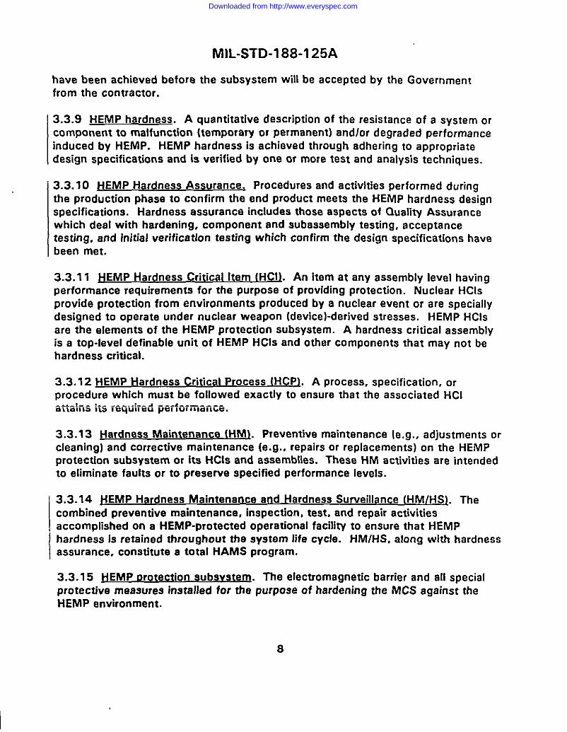
3.3.12 HEMP Hardness Critical Process (HCPL A process, specification, orprocedura which must be foIlowed exactly to ensure that tha associated HCIattains its required performance.
3.3.13 ~ HM\. Preventive maintenance [e.g., adjustments orcleaning) and corrective maintenance (e. g., rapairs or replacements) on tha HEMPprotection subsystem or its HCIS and assemblies. These HM activities are intendedto eliminate faults or to preserve specified performance levels.
3.3.14 HEMP Hardness Maintenance and Hardness Surveillance (HM/HS). Thecombined preventive maintenance, inspection, teat, and repair activitiesaccomplished on a HEMP-protected operational facility to ansure that HEMPhardness is retained throughout the system life cycle. HM/HS, along with herdnessassurance, constitute a total HAMS program.
3.3.15 &fEMP protection subsvstem. The electromagnetic barrier and all spatialprotective measures installad for tha purpose of hardening the MCS against thaHEMP environment.
8
I
Downloaded from http://www.everyspec.com

MlL-STD-l 88-1 25A
3.3.16 Jiard~ Surve [lance (HSLi Inspections and tests of the HEMP protectionsubsystem or its HCIS and assemblies. These HS activities ere Intended to observeand monitor the condition and performance of the hardening alementa and todetect faults.
3.3.17 Low-risk HEMP harw. A hardaning technique that features ahigh-quality electromagnetic barrier with minimized and protected POE. Virtually allmission-critical communications-electronics and support equipment are placed Inthe protected voluma enclosad by the barrier and oparata In a relatively benignelectromagnetic environment, Isolated from the extarnal HEMP atresses. Thelow-risk approach rasults In a well-defined HEMP protection subsystemconfiguration with Inherent testability.
3.3.18 Main barrier. The topological closed surface comprised of electromagneticbarrier components that represent the smallast, protected Interior voluma. Specialprotective volume walls that implnga on the Interior of a facility are an importantpart of this barrier.
3.3.19 Main barrier t)r~t ive deVicg. A protective device installed on anelectrical conductor that penetrates from the system exterior, through the facilityHEMP shield, and into the protected volume. Main barrier proactive devicas mustmeet the performance requirements of this standard (see 5.1.7).
3.3.20 fvlission-Critical Svs@rrts (MCS\. All communications-electronics andsupport equipment required to perform spacified critical missions that are requiredtrans and post nuclear attack. In tha context of this standard, MCS refar to behardened to perform missions specified to be accomplished In or after a HEMPenvironment.
I3.3.21 ~ton Sourc& Is a circuit consisting of a currant source in parallel withan impedance which is electrically equivalent to another electrical circuit.
3.3.22 Penetrating ~. Any electrical wire or cable or other conducthreobject, such as a metallic rod, which passas through the electromagnetic barrier.Penetrating conductors ara also called conductive POES.
3.3.23 penetration entrv area. That area of the elactromagnatic barrier where longpenetrating conductors (such as an alactdcal power feeder) and piping POES areconcentrated.
3.3.24 Point-of-Entrv (POE~. A location on the electromagnetic barrier where theshield is penetrated and HEMP energy may enter the protected volume unless an
9
Downloaded from http://www.everyspec.com

MlL-STD-l 88-1 25A
adequate POE protective devica is providad. POES ara classified as aparture POESor penetrating conductors according to the type of penetration. They ara alsoclassified as architectural, mechanical, structural, or electrical POES according tothe architectural-engineering discipline in which thay are usually encountered.
3.3.25 POE protective device or POE treatment. The proactive maasure used toprevent or limit HEMP enargy from entering the protected volume at a POE.Common POE protective devices include wavaguides-below-cutoff and closureplates for aperture POES, and filtars and electrical surge arrastars on penetratingconductors. The three categories of POE protective devicas for installation onpenetrating conductors are: main barrier protective davices, primary specialprotective devices, and secondary special protective devicas (saa 5.1.8.3).
3.3.26 Preventive ma intenanc~. Scheduled maintenance actions. These actionsare parformed on a regular basis. Preventive maintenance includes scheduledadjustments, cleaning and replacement of itams with Iimitad Iifatimes.
3.3.27 primary snecial rvotective device. A protective device installed on anelectrical conductor that penetrates from the system extarior into a specialprotective volume. A primary special protective device Is designed to provide themaximum attenuation possible without interfering with tha normal operationalelectrical signals that ara routed on the penetrating conductor.
3.3.28 protected volume. The threa-dimensional space enclosad by theelectromagnetic barrier, except for those spaces which are also within specialprotective volumes.
3.3.29 Pulsed current iniection (PCII. A test method for measuring performance ofa POE proactive device on a penetrating conductor. A HEMP thraat-ralatabletransient is injacted on the penetrating conductor at a point outside theelectromagnetic barrier and tha residual internal transiant stress is measured insidethe barrier.
3.3.30 ~~s. The electromagnetic fields, voltages, currents, orcharges which originate from the HEMP environment and penetrate into theprotected volume after attenuation by elements of the electromagnetic barrier.
3.3.31 Retrofit HEMP hardeninq. An action taken to modify in-service equipment.Retrofit HEMP hardening is tha installation or substantial upgrada of tha HEMPprotection subsystem for an axisting facility or equipment.
10
Downloaded from http://www.everyspec.com

MlL-STD-l 88-1 25A
3.3.32 $eco darv soecialn wotecti ve device. A protective device installed on anelectrical conductor that penetrates from a special protective volume into the mainprotectad volume. It is used only when necessary to augment the attenuationprovided by the primary special protective device and the connected equipmant.The total attenuation through the primary special protective device, the connectedequipment, and the secondary special protective device (see 5.1 .8.3.2.2), mustmeet the performance requirements of this atendard.
3.3.33 Shialdad enti Iaak deta ction - fSELDS~. Any of a class ofcommercially available instruments designed for checking shialding effectiveness inthe magnetic field test regime. Most of these instruments operate at one or morediscrete frequencies, oftan of the order of 100 kHz.
3.3.34 Soecial~otect ive ~. All HEMP hardening measures required inaddition to Implementation of the electromagnetic barrier. Special protectivemeasures are necessary for MCS outside the barrier, for MCS which are within theprotected volume and experlance damage or upset during verification testing, andin cases raquiring a special protective volume.
3.3.35 Soacial orotecti ve volumg. A region within the electromagnetic barrierwhere electromagnetic stresses due to HEMP may exceed the residual internalstress limits for the protected volume (see 5.1 .8.3). The special protective barriermay be a separate shield with protected penetrations; more commonly, shieldedcables or conduits and equipment cabinets and closad piping systems are used toprovide the needed electromagnetic isolation from the protacted volume.
3.3.36 Verification te stinq. Tests conducted for demonstrating thet the installadHEMP protection subsystem provides the required HEMP hardnass. These taste areperformed after the construction and acceptance tasting are complete and after theequipment is installad and functioning, to detarmine If the operational systemsuffers mission-aborting damage or upset due to simulated HEMP excitations.Verification is normally a Government-conductad test, and is not part of a facilityconstruction contract.
3.3.37 Vulnerable tv thr@@l (of an e~.. .
I The minimum stress level whichcauses the equipment to suffer definite dagradadon. In the context of thisstandard, the vulnerabiliW threshold is the minimum electromagnetic stress whichcauses mission-impacting damage or upset.
3.3.38 Waveouida betOw cl@-ff. A metallic waveguide whose primary purpose isto attenuate electromagnetic waves at frequencies below tfta cutoff frequency(rather than propagating waves at frequencies above cutoff). The cutoff frequency
11
Downloaded from http://www.everyspec.com
I
MlL-STD-l 88-1 25A
is determined by the transverse dimensions and geometry of the waveguide andproperties of the dielectric material in tha waveguide.
3.3.39 ~. An assembly of parallel waveguides-below-cutoff, with adjacent cells usually sharing common cell walls (see 5.1.5.2). Awaveguide-below-cutoff array is used when the area of the shiald apertura requiredto obtain adequate fluid flow within prassure drop limitations is larger than thepermissible area of e single waveguide-below-cutoff.
12
Downloaded from http://www.everyspec.com

MIL-STD-188-125A
4. GENERAL REOUfREMENTS
4.1 -.
4.1.1 ~. The need exists for uniform and effectivehardening, hardnass verification, and Hardnass Maintananca and HardnessSurveillance (HM/HS) of Fixad Ground-Based Command, Control. Communications,Computer, and Intalligance (FGB&l) systams that raqulre network Interoperabilityduring and after exposura to HEMP environments. In critical Ume-urgantapplications whare soma momentary upsats. as wall as damaga, ara mission-impacting, the hardening requirements Include stringent shlaldlng, POE protection,and special protective measures. Since normal operational experianca may notIndicata the condition of the HEMP protection subsystem, thorough verificationtesting and HM/HS after deployment are necesaa~. For additional Information,refar to supporting handbook MIL-HDBK-423, Volume 1, Fixed FaciIitlas.
4.1.2 ~ with r~ad reoul~. Elaments of the HEMP protectionsubsystem(s) can serva multipla purposes. For example, the electromagneticbarrier(s) can also ba usad to maat emanations security requirements. HEMPhardaning measuras should ba Integrated with those of othar electromagneticdisciplines, such as electromagnetic lnterferenca/elactromagnetlc compatibility,lightning protection, and TEMPEST, and with treatments for othar hardeningrequirements.
4.2 Hardness grouram ~. Hardness program managamen? for fixedground-based systems being HEMP hardenad IAW requiramenta of this standardshall implement the policy and procedures of DoD Diractive 5000.1 and thaaccompanying DoD Instruction 5000.2. Dasign, englneedng, fabrication. installa-tion, and testing activities shall ba managed to accomplish tha following objectives:
a. To provide a HEMP-protected systam daslgn basad upon verifiable perfor-mance specifications.
b. To verify hardness levels through a cost-affactlva program of testfng andanalysis.
c. During the acquisition process, to davelop a malntananceh.rrveillanceprogram that supports the operational phasa of life cycle HEMP hardness.
lHEMP PIannkIQ, aIUJ@8, design. tam pmmdures. last rewdn.a documentation, d reauirermmu for HhvHS progmm
devdopmont ●nd ●xecution ●re da8crib8d in MIL-HOSX-423, Voluma 1, Fix& Fuilldos.
13
Downloaded from http://www.everyspec.com

MlL-STD-l 88-1 25A
4.3 HEMP hardenina desir.rn. Facility protection against the HEMP threatenvironment specified in DoD-STD-2169 shall be achieved with an electromagneticbarrier and with additional special protective measures, as required. Theelectromagnetic barrier shall consist of the facility HEMP shield and protectivedevices for all POES. Special protective measures shall be implemented for
I hardening NICS which must be placed outside the barrier and for other specialcases. Rellabili~ (MIL-STD-785), maintainability (MIL-STD4$70), safety and humanengineering (MIL-STD-1472), testability (MIL-STD-21 65), and corrosion control(MIL-HDBK-729) shall be incorporated into the HEMP protection subsystem design.
4.3.1 FE ili ield. The facility HEMP shield shall be a continuously welded orbrazed metallic enclosure which meets or exceeds shielding effectivenessrequirements of this standard (sac 5.1 .3.1).
4.3.2 ~. The number of shield POES shall be limited to the minimum requiredfor operational, life-safety, and habitability purposes. Each POE shall be HEMPprotected with POE protective devices which satisfy performance requirements ofthis standard (see 5.1.4 through 5.1.7).
4.3.3 ~. All equipment required to perform critical time-urgent missions duringtrans- and post-attack shall be designated as MCS. MCS includes such items ascommunications-electronic equipment, data processing subsystems, command andcontrol equipment, local portions of hardened interconnects’, and critical supportsubsystems such as power generation, powar distribution, and environmentalcontrol.
4.3.3.1 MCS within the electromagnetic barrier. All MCS that will operatesatisfactorily and compatibly shall be installed within the electromagnetic barrier.No HEMP-unique performance characteristics are required in design and selection of
I MCS that will be housed within the barrier.
4.3.3.2 MCS ou .sid he I r ma neti barri r. MCS, such as a radio antenna\ or avapo~ced outside the electromagnetic
barrier, shall be provided with special protective measures (see 5.1.8) as requiredto ensure HEMP hardness in the HEMP threat environment.
4.3.3.3 HEMP-hardened electrical Dower. The facility shall be provided withHEMP-hardened electrical pawer generation and dktributlon capability sufficient to
‘Although rhey am not included within the 8COP8 of rh. document. tiEMP-hafdaned local imwconneccs at-d suwivable
long-haul comnnmication circuits to othar hardened kilitios in a network must be made available as required for missionoccomplishmant.
14
Downloaded from http://www.everyspec.com

MlL-STD-l 88-1 25A
perform trans- and post-attack missions, without reliance upon commercialelectrical power sources.
4.3.4 Soec al 9.t91w2ti ive ~. Special protective measuras shall beimplemented in cases whare HEMP hardness cannot ba achiaved with theelectromagnetic barrier alone. Additional shielding, transient suppression/attenuation devices, and equipment-ievel protection shali ba provided as required toachieve HEMP hardness. The three catagorias of cases requiring spatial protectivemeasures are as foilows:
MCS that must be iocated outside tha electromagnetic barrier and,thara;ore, is not protectad by tha barrlar (saa 5.1.8.1).
I b“MCS that is enclosed within the electromagnetic barrier and experiencesmission-impacting damage or upset during varificatlon testing, even though thabarrier elements satisfy all performance requlramants (see 5.1.8.2).
c. Spatial protective volumes and barriers to provida supplementaryisolation, when POE proactive davicas cannot satisfy the barrier requlremantewithout interfering with facility oparation (saa 5.1.8.3).
4.4 J+EMP te~. Tha HEMP testing program shali demonstrate that hardnassperformance requirements have been satisfied and that the required HEMPhardnass has been achieved. This program shali include quality assurance testingduring faciiity construction and equipment installation, acceptance testfng for theelectromagnetic barrier and special protective measures, and verification tasting ofthe compieted and operational facility.
4.4.1 Clualitv ass uranc~. A qualiW assuranca program IAW FED-STD-368and MiL-Q-9858 shaii be implemented during systam construction and installationto demonstrate that the HEMP protection subsystem matariais and componentscomply with performance requirements of this standard. The quality assurance testprocedures and results shali be documental for use as basaline configuration andperformance data for the HM/HS program.
4.4.2 ~cceotance testing. Acceptance of the HEMP protection subsystem shali babased upon successful demonstrations of compliance with hardness performancerequirements of this standard. HEMP acceptance tests of the electromagneticbarrier and speciai protective measures shail be conducted after ail relatedconstruction work has been completed. Acceptance test procedures and resultsshail be documented for usa as baseline configuration and performance data.
15
Downloaded from http://www.everyspec.com

MlL-STD-l 88-1 25A
4.4.3 Verification testing. After completion of the HEMP protection subsystem,installation, operational checks and acceptance tasting of the facility equipment,HEMP hardness of the facility shall be verifiad through a program of tests and
i.SllppOrtiflg analysis. The verification program shall providaa definitive statementon the HEMP hardness of critical tima-urgent mission functions at the facility undertest. Verification test procedures and results shall be documented for use asbaseline configuration and performance data.
14.5 HM/HS.
4.5.1 HM/HSrxoaram development. HM/HS considerations shall be included inthe facility planning and design phases to facilitatehfe cycle survivabilkyand thedevelopment of an effective HM/HS program. The HM/HS program shall bedesigned to maintain the protection subsystem at a Iavel .of performance that meetsthe requirements in this standard.
4.5.2 HM/HS oroaram implementation. During “the verification phase, baselinedata shall ba obtained for the HM/HS program. The HM/HS program shall beimplemented in the operation and support phase of the facility life cycle.Effectiveness of the HM/HS program for maintaining the HEMP protectionsubsystem performance at the requirad level shall be periodically reviewed, and
1Program revisions shall be made when required.
16
Downloaded from http://www.everyspec.com

MlL-STD-l 88-1 25A
5. DETAILED REQUIREMENTS
5.1 fixecl Svst emS,
5.1.1 J-fEMp o ot~.r i
5.1.1.1 ~n etic barrier ~. The electromagnetic barrier, consistingof the facility HEMP shield and POE protective devices, shall be configured toaccomplish the following technical requirements:
a. To enclose all MCS except those equipments such as radio antennas,evaporative heat exchangers, or external security sensors, which will not function
properly if placed within the protected volume.
b. To minimize the number of POES.
c. To avoid requirements for special protective measures internal to thebarrier .
d. To facilitate HEMP acceptance and verification testing.
e. To minimize requirements for scheduled HM.
5.1.1.2 ~. As a design objective, there should be a singlepenetration entry area on the electromagnetic barrier for all piping and electricalPOES except those connected to external conductors less than 10 m (32.8 ft) inlength. The penetration entry area shall be located as far from normal andemergency personnel and equipment eccesses and ventilation POES as is permittedby the facility floor plan.
5.1.2 Fac ilitv aroundinq.
5.1.2.1 Wirrotent ial around olane. Fixed ground-based C’1 facilities shall begrounded using the equipotential ground plane method IAW MlL-STD-l 88-124 andguidance in MIL-HDBK-419. The facility HEMP shield shall form a major portion ofthe equipotential ground plane.
5.1.2.2 Wndina to the facilitv HFM P shi~. Grounds for equipment andstructures enclosed within the protected volume shall be electrically bonded to theinside surface of the shield by the shortest practical paths, including via the raisedfloor structure. Grounds for equipment and structures outside the electromagnetic
17
Downloaded from http://www.everyspec.com

MlL-STD-l 88-1 25A
barrier shall be electrically bonded to the outside surface of the shield or to theearth electrode subsystem. Ground cables used to connect the facility shield
(equipotenlial ground plane) to the earth electrode subsystem shall be electricallybonded to the outside surface of the shield, and at least one such ground cableshall be located at the penetration entry area. All grounding connections to the
facility HEMP shield shall be made in a manner which does not create POES.
5.1.3 Facilitv HEMP shield.
5.1.3.1 Shieldina effectiveness. The facility HEMP shield, with all POE protectivedevices installed, shall provide at least the minimum shielding effectiveness shownon figure 1.
5.1.3.2 Shield construction. The facility HEMP shield, exclusive of its POES, shallbe a continuous conductive enclosure such as steel or copper, closed on all wall,ceiling, and floor surfaces. All seams and joints between adjacent panels shall becontinuously welded (for steel shields) or continuously brazed (for comer shields).Welding and brazing shall be performed using Procedures and personnel qualified inaccordance with MIL-STD-248.
5.1.3.3 Shield monitoring Car)ability. A built-in test capability to at leastqualitatively monitor for electromagnetic shield leakage shall be provided (see5.1.11).
5.1 .3.4 Shield construction aualitv assurance.
5.1.3.4.1 In-oroaress inspection of welded and brazed seares. In-progressinspection of welded and brazed seams and joints shall proceed continuously inparallel with the shield fabrication and assembly activiw. The quality of all shieldseams and joints, including those used for installation of POE protective devices,shall be monitored with visual and magnetic Particle inspection, SELDSmeasurements, or dye penetrant testing.
5.1.3.4.2 Shieldinca effectiveness survey. After the shield is closed but beforeinterior equipments and finishes are installed, a shielding effectiveness survey shallbe performed. SELDS testing and plane wave shialding effectiveness tests shall beemployed. Shielding defects found during the survey must be corrected, retasted,and shown to provide the required performance before the interior equipment andfinishes are installed.
18
Downloaded from http://www.everyspec.com

I( 1, ;; !! ii
110.
I1
1111
111
I1
1I
1111
1[I
I1
1111
111
111
8111
11
11
1111
1I
II
1111
11f
Ir
11,,,
1,
Ir
lllrr
II I
100
I IE
LE
CT
RIC
AN
DP
LA
NE
W/W
E10
cm
90-
SE
=10
0
zi
WA
VE
GU
IDE
-BE
LO
W-C
UT
OF
F
;I
:80
-I
/,I I
SE
PW
=
v-l
I/,
,;70
I/
I/
HI
/I
~13
4.,J
~’.
z60
-/
II
11I
i=
~1“
/I I
Ih
*50
I/
II
-1u
I/
Ia
w L40
i/
;I
au
./
MA
GN
ET
ICI
cnw
I/
aw
1/S
EM
=20
10g
f–62
.l~
I-i
z30
-
5
j’
Ii
‘N
ii20
/~
zI
;m
10-
“i
II
/I I
I
o-
111
IllI
IIJ1
t11
11,1
11
11
tttl
la
I11
1111
1I
1111
111
It
1111
111
11
IItti
103
I10
4I
~Os
,.6~0
7I
~o
B,09
~olo
j($l
1.3
x10
31.
4x
104
2x
10’
1.5
x10
9
FR
EQ
UE
NC
Y-
f(t
fz)
~in
wm
HE
MP
shie
ldin
fref
fect
iven
ess
rerr
llire
men
ts(m
easu
rcrl
IAW
nro
ced
wes
of
AQ
~A~.
Downloaded from http://www.everyspec.com

MIL-STD 188-1 25A
VA
D
a. Waveguide entryway.
FACILITY HEMPSHIELD
wfATHSRDOOR
~ WEATHER ENCLOSURE(FOR oUTSIOE OOORSI
b. Vestibule entryway.
figure 2 Tvoical wavea uide and vestibule enwvwavs
20
Downloaded from http://www.everyspec.com

MIL-STD-188-125A
5.1.3.5 shield ac~. After completion of the shield and afterinstallation of the POE proactive devices, intarnal equipments, and finish workprovidad under tha construction contract, the shield acceptance test shall beconducted to determina if the facility shield performs IAW minimum requirementsof figure 1. The test shall be conducted with POES and their protective devices ina normal operating configuration, using shielding effectiveness test procedures ofappendix A. All defects found during the acceptance testing shall be corrected,retasted, and shown to provide the required performance bafore the installation ofcommunications-electronics aquipment.
5.1.3.5.1 Facilitv shield ~. If POES are added or tha facility HEMPshield is breached and repaired after acceptance, shield acceptance tasting in theaffected area shall be repeated.
5.1.4 Architectural POE.
5.1.4.1 HEM P o-on fo r arc~l PO~. HEMP protection for architecturalPO ES, including personnel entryways and exits and equipment accesses throughthe facility shield, shall be provided with electromagnetic closure,waveguide-below-cutoff techniques, or combinations of closure andwaveguides-below-cutoff.
5.1.4.1.1 ~ for ~ POE -t ive deviceS. All weldedor brazed seams and joints required for installation of architectural POE protectivedevices shall be monitorad under the program of in-prograss inspection of weldedand brazed seams (see 5.1.3.4. 1). Shielded doors and other closure or accesscovers shall ba subjacted to electromagnetic and mechanical quality assurancetests to demonstrate acceptable performance.
5.1.4.1.2 Accemance testino for arch-l POE nr~ct ive device~.Acceptance testing for architectural POE protective devices shall be conductedusing shielding effectiveness test procedures of appendix A.
5.1.4.2 HEMP protection for all normal andemergency parsonnel entryways and axits shall be provided with a two-doorshielded waveguide-below-cutoff ent~way or with a two-door shialded vestibule(figure 2). As dasign objectives, the number of personnel entryways and exitsshould be constrained to the minimum requirements of NFPA 101 and the mainpersonnel entryway should be a waveguide-below-cutoff.
5.1.4.2.1 Waveauide entrvwav dimensions. When a waveguide-below-cutoffentryway is used, haight and width of the waveguide shall each not exceed 2.44 m
21
Downloaded from http://www.everyspec.com

MlL-STD-l 88-1 25A
(8 ft), and the length of the waveguide along its shortest path shall be at least fivetimes the diagonal dimension of the cross-section. As a design objective, no
electrical wiring, piping, or other conductors should run longitudinally i’nside thewaveguide entryway. Where electrical wiring cannot be eliminated from theentryway, it shall be run in metal conduit. All conduits and other groundableconductors such as pipes or handrails in the waveguide entryway shall beelectrically bonded to the entryway shield at intervals not exceeding 1 m (3.3 ft).
5.1 .4.2.2 Entwwav shield. The entryway shield shall comply with the samerequirements applicable to the facility HEMP shield (see 5.1 .3). All entryway POES,either into the facility protected volume or to the outside, shall comply with thesame requirements applicable to other POES through the electromagnetic barrier(see 5.1.5 through 5.1.7).
5.1.4.2.3 Entwwav shielded doors. Entryway shielded door frames shall bewelded or brazed into the entryway shield. When installed, vestibule shield doorsshall provide at least the minimum shielding effectiveness shown in figure 1.Waveguide entryway doors shall provide at least the minimum electric and planewave shielding effectiveness shown on figure 1, but are not required to satisfy themagnetic shielding effectiveness criteria. A weather enclosure with appropriateenvironmental controls shall be provided to Protect exterior shield doors fromcorrosion and exposure to blown dust and other natural elements.
5.1.4.2.4 Entrvwav interlocks and alarms. The entryway shield doors shall beprovided with interlocks to ensure that at least one of the shield doors remainsclosed except during emergency evacuations. The ent~way shield doors shall beprovided with an alarm to indicate that the interlock has been overridden or thatboth shield doors are open.
5.1.4.3 EauiDment accesses. A protected equipment access POE shall beprovided only when movement of the equipment through a personnel entryway is
not practical. HEMP protection for equipment accesses through the facility HEMPshield shall be provided with electromagnetic closure. The metal access cover shallbe continuously seam welded in place, if anticipated usage is less than once per 3years, and shall be radio frequency gasketed and secured by a closure mechanismwhich ensures a proper gasket seal, when expected usage is more frequent. Whenclosed, the equipment access covers shall provide at least the minimum shieldingeffectiveness shown on figure 1. A weather enclosure shall be provided to protectexterior gasketed access covers from corrosion and exposure to blown dust andother natural elements.
22
Downloaded from http://www.everyspec.com

MlL-STD-l 88-1 25A
5.1.5 Mechanical POE.
5.1.5.1 J-1EMP wotection for mechaoi.cal POES. HEMP protection for mechanicalPOES, including piping and vefltilatiOfl Penetrations through the facility HEMPshield, shall be provided with wavaguide-below-cutoff techniques. As a designobjective, the number of piping PCIES should be constrained to fewer than 20 andthe number of ventilation POES should be constrained to fewer than 10.
5.1.5.1.1 Q.ualitv assura ce for mecn hanical POE txote ctive deviceS. All weldedand brazed saams and joints required for installation of mechanical POE protectivedevices, including those for piping and ventilation penetrations, shall be monitored
under the program of in-progress inspection of welded and brazed seams and joints
(see 5.1.3.4.1).
5.1.5.1.2 I POE mote ctive dev~. Acceptancetesting for mechanical POE protective devices, including those for piping andventilation penetrations, shall be conducted using shielding effectiveness test
procedures of appendix A.
5.1.5.2 Pioina POES. Piping shall penetrate the facility HEMP shield as a pipesection which is configured as a sin91e waveguide-below-cutoff or awaveguide-below-cutoff array (figure 3). Dielectric hoses or pipes shall be
converted to metal piping before Penetrating the shiald. The presence of theprotected piping POE shall not degrade shielding effectiveness of the facility HEMPshield below the minimum requirements of figure 1.
5.1.5.2.1 Mets Ilic aioina waveauide dimens ions. The inside diameter of a singlewave-guide-below-cutoff and each of the transverse cell dimensions in awaveguide-below-cutoff array shall not exceed 10 cm (4 in), except where aspecial protective volume will be established (see 5.1.8.3.1). The length of thewaveguide section shall be at least five times the inside diameter of a singlewaveguide-below-cutoff or at least five times the transverse cell diagonaldimension in a waveguide-below-cutoff array.
5.1.5.2.2 Metallic oioina waveauide ca n~. All joints and couplings in thewaveguide section shall be circumferenliallY welded or brazed, and the waveguide-below-cutoff shall be circumferentiallY welded or brazed to the facility HEMP shieldat the POE. Cell walls of a Waveguide-below-cmoff array shall be metallic, andthere shall be continuous electrical bonds aI all intersections and between the cellwalls and the waveguide wall. NO dielectric (glass, plastic, etc.) pipe lining shall bepermitted in the waveguide section. Extarnal and internal piping shall be connected
23
Downloaded from http://www.everyspec.com
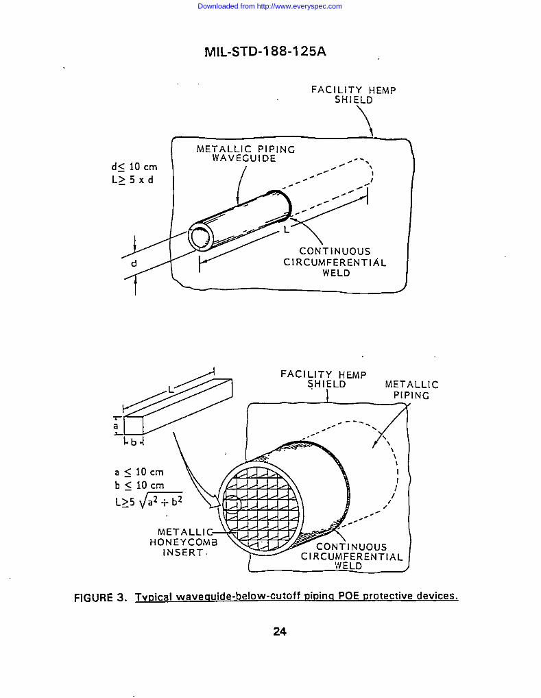
d< 10 cm
L~5xd
MlL-STD-l 88-1 25A
FACILITY HEMPSHIELD
T \
~{
CONTINUOUSCIRCUMFERENTIAL
WELD
/
LLICNG
FIG URE3. TvLYical wavecwide-below-cutoff oiDinq POEorotective devices.
24
Downloaded from http://www.everyspec.com
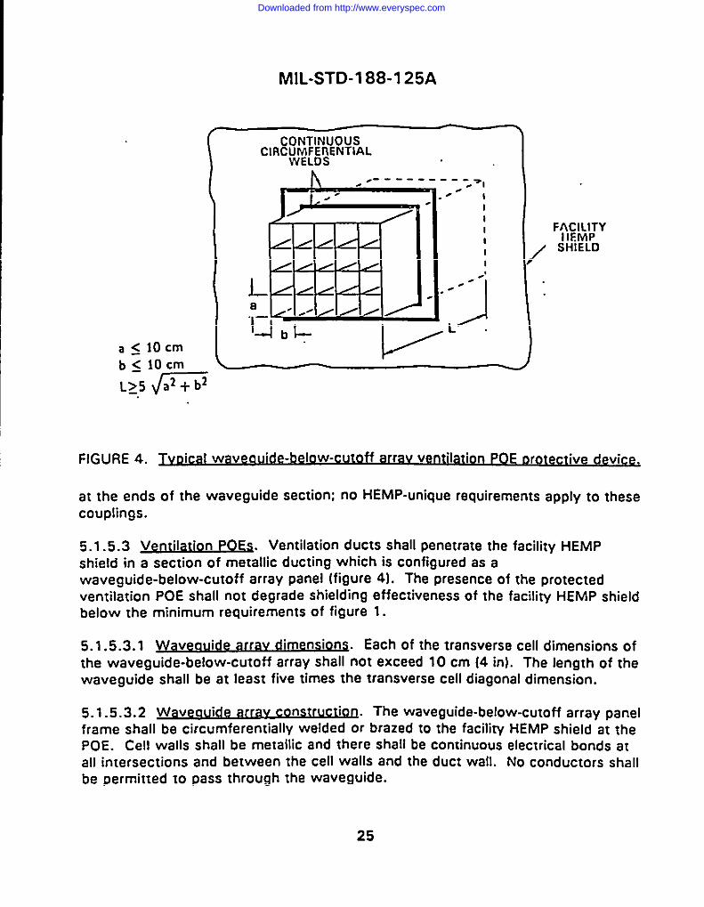
MIL-STD-188-125A
a<l Ocm
F~lCfilJY
SHIELD
FIGURE 4. ~vDical wave@ -below-cu:off ar avr ventilation POE D otectr ive devic~
at the ends of the waveguide section; no l+EMp-unique requirements apply to these
couplings.
5.1.5.3 Ventilation POE% Ventilation ducts shall panetrate the facility HEMPshield in a section of metallic ducting which is configured as awaveguide-balow-cutoff array panel (fi9Ure 4). The presence of the protectedventilation POE shall not degrade shielding effectiveness of tha facility HEMP shieldbelow the minimum requirements of figure 1.
5.1.5.3.1 Waveauide arrav dimension~. Each of the transversal cell dimensions ofthe waveguide-below-cutoff array shall not exceed 10 cm (4 in). The length of thewaveguida shall be at least five times the transverse cell diagonal dimension.
5.1.5.3.2 Waveouide arrav const rM@CLD. The waveguide-below-cutoff array panelframe shall be circumferentially welded or brazed to the facility HEMP shiald at thePOE. Cell walls shall be metallic and there shall be continuous electrical bonds atall intersections and between the cell walls and the duct wall. No conductors shallbe permit~ed to pass through the waveguide.
25
Downloaded from http://www.everyspec.com

MlL-STD-l 88-1 25A
5.I.6 Structural POE.
5.1.6.1 HEMP motection for structural pOES. HEMp Protection for structuralPOES, including beams, columns, and other metallic strKtL.Jral elements which mustpenetrate the electromagnetic barrier, shall be provided with continuously weldedor brazed seams and joints between the Penetrating element and the facility shield.As a design objective, the facilitY should be configured to minimize the number ofmetallic structural elements required to penetrate the barrier. Nonmetallic structura[elements shall not penetrate the electromagnetic barrier.
5.1.6.2 Quali tv assurance for structural pOE motective treatments. All weldedand brazed seams and joints required for structural POE treatments shall bemonitored under the Program of ifl-Pro9ress in5PeCti0n of welded and brazed seams(see 5.1.3.4.1).
5.1.6.3 A~. Acceptancetesting for structural POE protective treatments shall be conducted using shieldingeffectiveness test procedures of appendix A.
15.1.7 Electrical POE.
5.1.7.1 HEMP motection for electrical POES. HEMP protection for electrical POES,including all power, communications and control Penetrating conductors whethershielded or unshielded, shall be provided with main barrier transient suppressiordattenuation devices (except under conditions identified in 5.1 .7.9).
5.1.7.1.1 Electrical POE main barrier Protective device requirements. A main
barrier transient suppressionlafienuation device shall consist of an electrical surgearrester and additional linear and nonlinear elements, as required. The varistorvoltage at 1 mA direct current d.c. (for a metal oxide varistor) or the d.c.breakdown voltage (for a spark gaP) shall be 150 to 250 percent of the peakoperating voltage on the line. The main barrier protective device shall limit theresidual internal transient stress to the maximum Prescribed for each class ofelectrical POE, when prescribed pulses are injected at its external terminal (seetable l). Additionally, the main barrier Protective device shall be rated to withstandat least 2000 short pulses at the prescribed peak injection current without damageor unacceptable performance degradation, as defined in test procedures ofappendix B.
5.1.7.1.2 Electrical POE main barrier orote ctive devic e installation. Electrical POEmain barrier protective devices shall be installed in the configuration shown onfigure 5. The external and internal conduits and Compaflment covers do not have
26
Downloaded from http://www.everyspec.com
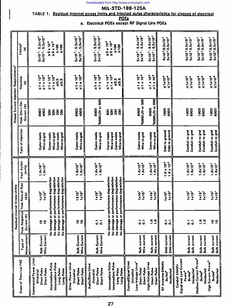
Ml L-STD-l 88-1 25A
I TABLE 1. flesidual internal s~ OU se ~I istics for classes of electr icpJ
a. Electrical POESexceptRFShad Use POES
27
Downloaded from http://www.everyspec.com
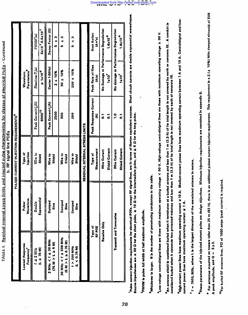
lAfJ
Lk
1.fl
esic
hm
lin
tern
alst
ress
limit
san
din
iecl
edp
uls
ech
arac
teri
stic
sfo
rcl
asse
scd
elec
tric
alP
LIE
S.
C“,
>ti”
ued
b.R
Fsi
gnal
line
POES
tPU
LSED
CURR
ENT
lNJE
CTfO
NRE
OLO
REM
ENTS
O[
LOW
.*I
R.sP
oI18
9Pu
lse,
TVPa
ofW
.vef
orm
Fraq
u*nc
y’W
avef
orm
InJe
..tlo
mP.
rmne
lem
~
-mm
‘“”’
~~;4
”A’
‘1x1
046x
f~:J
::07
Rlm
allm
a-T,
ld
2MHz
<fs3
0MHz
Dam
pad
Wlr*
toP.
akCu
rmnl
-lPIA
lC.
nt.r
l-lM
Hz}
176
M>
L>6M
ID.
c.y
Fact
or[0
)Sh
.Sh
ldd
2600
2*
10%
5*3
30M
H,<
fs2
00M
HzDa
mp.
dW
lroto
900
30*
10%
16M
>L>
0.76
MI
6*3
Sin.
Shld
d
I>2
00M
fbDa
mp-
dw
ho10
260
200
*10
%6*
3IL
<0.
7SM
}Si
n.S
hb
ld
RE
SID
UA
LIN
TE
RN
AL
ST
RE
SS
LIM
ITS
Tw
.o
fT
yp*
of
Pan
kR
..pm
.*C
un
.nt
P.a
kR
at.
of
RI,.
Ro
ot
A.t
lon
RF
PO
EM
msu
r.m
ent
IAI
IA!.
]\
R.U
IV.
On
ly
lA#.
13
W7r
.C
.n.n
t0.
1N
oO
amaL
!ao
rP
.rto
rman
c#O
.ora
dad
.n
I~
Sh
l.ld
Cu
m.n
t0.
1lx
lo~
l.axl
o~
Tm
no
mh
●nd
Tro
n.w
lwm
w,.
Cu
”.”t
1.0
NO
dsm
.g.
wP
.rf.
rman
eoD
.gra
dat
ion
-1
Sh
ldd
curr
ant
0.1
Illlo
’I
1.6n
10a
o L%
&a
wo
nt
lnkc
drnt
.qu
lr.r
tmn
fsfo
r.I.
cfrf
.dP
OG
..x
c.p
tR
Fd
on
dIf
...,
w.
In1.
rm.
of
No
rto
n.q
ulv
al.n
t.O
IUW
..S
ho
rtd
ratf
fcu
m.”
fmw
.d
ou
bl.
●xp
m.n
tlal
wa.
..h
ap...
m
So
w-
Imp
.dan
a.w
.>
SO
Lk
far
tha
aho
rfp
ufs
.,z
10L
E1-
!fm
ht.
rm.d
late
pu
b..
and
zS
Ofo
rfh
.la
wPu
ls..
OJ
L‘F
WHM
bPU
18.
lull
wfd
Ih.S
hdl
max
imum
●m
pfflu
de.
N Uf
‘WN
du
vw18
!ue.
r.N
bd
un
um
b.:
of
p...
fmtg
.gco
nd
ucf
rnkn
fh.
cab
!..
D
‘Lo
w-v
dt.
wcc
mu
dld
g.d
Um
.w
them
wit
hm
.xfm
um
op
.r.d
no
VO
W*O
.<9
0V
.H
igh
-vo
ft.g
.o
on
trd
i.len
dfl
...m
.th
oa.
wft
hm
.xfm
um
c.p.
ralln
ovd
l.a.
>90
V
‘An
mt.
nn
a.h
fdd
bm
end
d.m
db
ud
.dw
h.n
ht.
rmln
at.s
●●
bw
lod
●n
ten
n.
●n
dIn
.lh
.n1
m13
.3W
of
1!s
tota
lfa
n@
hla
no
to
ovm
md
by
.ari
ho
rco
tmr.
t.fi
ll..
A.o
nd
ult
1.em
dd
u.d
bu
tf.d
wh
anh
com
ma
W.
pm
t.cf
.dvd
um
..●
nd
1...
than
1m
[3.3
ftl
of
ha
tota
lI.n
gIh
bn
ot
a.vs
md
by
..rth
of
cww
rata
fill.
‘Hf&
-wrr
anl
po
w.r
ffn
..h
av.
m.x
fmu
mO
pu
.tln
aw
rr.n
t>1
0A
.M
.dlu
m.c
urr
.nt
po
w.r
II”..
h.w
max
im.m
op
.rat
ing
wr?
.mb
.fw
..n1
An
nd
10A
.C
.ntr
olld
gn
dan
dlo
w.
an.n
tP
.w.r
Un
.sham
mm
hm
um
op
.ra
tln
.aw
rr.n
ts
1A
.
‘1-
160k
MH
z,w
h.r
.L
lotf
uIa
ro*a
td
lm.n
do
no
fth
.a.
.od
at.d
ante
nn
aIn
met
er..
‘TIU
.ep
ar.m
.t.r
.o
fth
ah
j.cfo
dcu
rran
tP
uk
are
ded
gn
ob
].ct
lv...
Mln
!rn
.rn
I.j.c
d.n
r.q
”lr.
m.n
tsat
..o
nta
ln.d
Inap
p.n
dfx
S.
‘F
or
●nt.
nn
a.m
.um
.do
nt.
w.r
ata
ller
than
25m
IE2
W,
ther
e1.
anad
dlt
l.nn
lp
ul..
deu
m.n
tIn
ject
ion
r.q
.lr.m
.nt.
TM
.re
qu
lr.m
.nt
1.a
2I*
10%
IM
Hz
dam
ped
dm
m.ld
of
500
Ap
eak
amp
litu
de.
and
O-
6*3
.
IOF
O,
bu
rled
RF
.nta
.”.
II...
.P
CI
.f10
00am
p.
fp..k
.urr
..1l
1.re
qu
ired
.
Downloaded from http://www.everyspec.com

MlL-STD-l 88-1 25A
m
29
Downloaded from http://www.everyspec.com

MIL-STD 188-1 25A
shielding requirements as part of the electromagnetic barrier, but shielding may benecessary as a special protective measure (see 5.1.8) or to satis~ otherelectromagnetic requirements. The presence of the protected electrical POE shallnot degrade shielding effectiveness of the facility HEMP shield below minimumrequirements of figure 1.
5.1.7.2 Qualitv assurance for ele ctrical POE main barrier Drot ective deviceS. All
welded and brazed seams and joints required for installation of electrical POE mainbarrier protective devices shall be monitored under the program of in-progressinspection of welded and brazed seams (See 5.1.3.4.1). Transient suppression/attenuation devices shall be subjected to electrical quality assurance tests todemonstrate acceptable performance.
5.1.7.3 AccerM ante testina of electrical POE main barrier orotective devices.Acceptance testing of electrical POE main barrier protective devices shall beconducted using the pulsed current injection test procedures of appendix B.
5.1.7.4 Commercial electrical oower feeder POES. A main barrier transientsuppression/attenuation device shall be provided on each penetrating conductor ofa commercial electrical power feeder POE. The section of the commercial powerfeeder immediately outside the electromagnetic barrier shall be buried for a lengthof at least 15.2 m (50 ft). As a design objective, a maximum of two commercialelectrical power feeders should penetrate the facility HEMP shield.
5.1.7.4.1 Commercial crower POE main barrier motective device reouirements. ANorton source, with a 8000 A short circuit current with s 10 ns risetime and 500ns FWHM, and source impedance 2 60 f2, connected to a penetrating conductorat the POE main barrier protective device external terminal, shall produce a residualinternal transient stress no greater than 10 A and shall not cause device damage orperformance degradation.’ A Norton source with a short circuit current of 500 Awith s 1 MS risetime and 5 ms FWHM, and source impedance 2 10 f), connected
at the POE main barrier protective device terminal, shall not cause device damageor performance degradation.’ A Norton source with a 200 A short circuit currentwith s 0.5 s risetime and 100 s FWHM, and source impedance 2 5 Ll, connectedat the POE main barrier protective device terminal, shall not cause device damageor performance degradation.’ The E3 PCI pulser will be attached/installed on theprimary side of the power transformer if one exists in series with the electrical POEbeing tested. If a POE main barrier protective device cannot be designed to satisfy
‘Common mcde PCI. waveform detils of the injected pulse., ad additional conmrrnnls m the rkd.sl imernd Iransie”t
sums are contained in tnbla L circuit test confi~ration information is c.ntined in U!. PCl 1..1 procedure. of appendx 0.
30
Downloaded from http://www.everyspec.com

MIL-STD 188-1 25A
the residual internal stress limits without interfering with operation signals that it isrequired to pass, a special protective volume shall be established (see 5.1.8.3.2).As a design objective, each commercial Power feadar should be provided with adevice to disconnect the incoming lines automatically if a HEMP event occurs ormanually during alert conditions.
5.1.7.5 ~1 001“ wer feeder ~. A main barriar transient suppression/attenuation device shall be provided on each penetrating conductor of electricalpower feeder POES that SUPPlY internal Power to equipment outside theelectromagnetic barrier. As a design objective, Internal power should be suppliedonly to MCS outside the electromagnetic barrier. Nonessential equipment outsidethe barrier should be powered from an external source.
5.1.7.5.1 ~1 oower POF ma In ~ device reouir~. ANorton source, with a 8000 A short circuit current withs 10 ns risetime and 500ns FWHM, and source impedance z 600, connected to a penetrating conductorat the POE main barrier protective device external terminal, shall produce a residualinternal transient stress no greater than 10 A and shall not cause device damage orperformance degradation.’ If a POE main barrier protective device cannot bedesigned to satisfy the residual internal stress limits without interfering withoperational signals that it is required to pass, a special protective volume shall beestablished (see 5.1 .8.3.2).
5.1.7.6 Audio ~ line POES.
5.1.7.6.1 ~da rd q@g and ~. All voice and data lines, whether shialdedor unshielded, shall be converted to fiber optics outside the electromagnetic barrierand shall penetrate the facility HEMP shiald on all-dielectric fiber optic cables.Electro-optic equipment outside the electromagnetic barrier shall ba protected usingspecial protective measures (see 5.1.8. 1), if the associated audio or data line ismission essential. The fiber optic cable POE shall ba protected with a waveguide-below-cutoff protective device.
5.1.7 .6.1.1 Fiber ootic waveqL@2@!ow-cuto&9LtXiXl ive de vi~. The insidediameter of a fiber optic waveguide-below-cutoff shall not exceed 10 cm (4 in).The length of the waveguide shall be at least five times the inside diameter of thewaveguide-balow-cutoff.
5.1.7 .6.1.2 Fiber ootic waveuuide-below-cutoff D m e der “v vice con~ i n. Alljoints and couplings in the waveguide shall be circumferentially welded or brazed,and the waveguide-below-cutoff protective devica shall be circumferentially welded
31
Downloaded from http://www.everyspec.com

MIL-STD 188-1 25A
or brazed to the facility HEMP shield at the POE. NO conductors or conductingfluids shall be permitted to pass through the waveguide; the waveguide-below-cutoff protective device shall be filled or its ends shall be capped to preventinadvertent insertion of conductors.
5.1.7.6.2 Nonstandard audio and data POE main barrier ttrotective devicerequirements. A main barrier transient suppression/attenuation device shall beprovided on each penetrating conductor of shielded or unshielded nonstandardaudio or data lines that cannot be Practically converted to fiber optics. As a designobjective, a maximum of 20 such nonstandard audio or data lines are allowed topenetrate the facility HEMP shield.
5.1.7 .6.2.1 Nonstandard audio and data POE main barrier protective devicerequirements. A Norton source, with an 8000/s/N or 500 A short circuit currentwith s 10 ns risetime and 500 ns FWHM (where N is the number of penetratingconductors in the audio or data cable and the larger amplitude is chosen), andsource impedance = 60 CL connected to a penetrating conductor at the POE mainbarrier protective device external terminal, shall produce a residual internal transientstress no greater than 0.1 A and shall not cause device damage or performancedegradation.’ A Norton source with a 500 A short circuit current with s 1 USrisetime and 5 ms FWHM, and source impedance a 10 Q, connected at the POEmain barrier protective device terminal, shall not cause device damage orperformance degradation.’ A Norton source with a 200 A short circuit current witha s 0.5 s risetime and a 100s FWHM, and source impedance 2 5 fl connected atthe POE main barrier protective device 5 terminal, shall not cause device damage orperformance degradation.’ If a POE main barrier protective device cannot bedesigned to satisfy the residual internal transient stress limits without interferingwith operational signals it is required to pass, a special protective volume shall beestablished (see 5.1 .8.3.2).
5.1.7.7 Electrical control and sional line POES. A main barrier transientsuppression/ attenuation device shall be provided on each penetrating conductor ofelectrical control and signal lines, whether shielded or unshielded. As a designobjective, the number of control and signal lines Penetrating the facility HEMPshield should be minimized. Nonmetallic fiber optic lines do not require a transientsuppression/ attenuation device at the barrier.
~hen a trwwfonner in in series and on the ‘dirty” side of the protecdve d.viceitmniar, then tie tranafommr is
consid6r6d rhe main barrier POEprotective deuce for E3 testino.
32
Downloaded from http://www.everyspec.com

MIL-STD 188-1 25A
5.1.7.7.1 POE maim~rrier protective device re~ for control and sioncJin r“~ V. A Nonon source, with an 80001dN or500 A short circuit current with s 10 ns risetime and 500 ns FWHM (whara N isthe number of penetrating conductors in the control or signal cabla and the largeramplitude is chosen), and sourca impadanca 2 60 Q, connected to a penetratingconductor at the POE main barrier protective device external terminal, shall producea residual internal transient stress no greater than 0.1 A and shall not cause devicedamage or performance degradation. 4 If a POE main barrier protective devicecannot be designed to satisfy the residual internal transiant stress limits withoutinterfering with operational signals it is required to pass, a special protectivevolume shall ba establishad (see 5.1.8.3.2).
5. I.7.7.2 POE ~ orotectwe de ice re~s for - and si~lines 00 eratino at o eater thanr V. A ;orton source, with an 8000/~N A or 50090A short circuit current with s 10 ns risetime and 500 ns FWHM [where N is thenumber of penetrating conductors in the control or signal cable and the larger
amplitude is chosen), and source impedance 2 600, connected .to a penetrating
conductor at the POE main barrier proactive device external terminal, shall producea residual internal transient stress no greater than 1 A and shall not cause devicedamage or performance degradation.’ If a POE main barrier protective davicecannot be designed to satisfy tha residual internal transient stress limits withoutinterfering with operational signals it is required to pass, a special proactivevolume shall be established (see 5.1 .8.3.2).
I5.1.7.8 J3Fcommu nicat ions anta nna hne PO= . A main barrier transiantsuppression/attenuation device shall be provided on signal-carrying conductors ofall penetrating RF communications antenna lines. The antenna cable shields shallbe circumferantially bonded to the facility HEMP shiald at the POE.
I 5.1.7.8.1 ~ntenn a line POF ma n bai rrier o~ti ve device reouireme~.
I Contorre5.1.7 .8.1.1 ~ianal r iniection f ive- A pulse of theprescribed waveform and amplitude, occurring on the signal-carrying conductor atthe external terminal of a receive-only antenna line POE main barrier protectivedevice, shall produce residual internal transient stresses no greater than 0.1 A onthe signal-carving conductor and shield and shall not cause device damage orperformance degradation.’ The pulse waveform and amplitude are determined bythe lowest characteristic response frequency, f, which is 1501L MHz (where L isthe largest dimension of the associated antenna in meters). The prescribed pulse isan 8000 A double exponential with 10 ns risetime and 500 ns FWHM, where thelowest characteristic response frequency is less than 2 MHz .4 The prescribed pulse
33
Downloaded from http://www.everyspec.com

MIL-STD 188-1 25A
is a 2 MHz damped sinusoid with 2500 A peak current, where the lowest responsefrequency is 2 MHz to 30 MHz.4 The prescribed pulse is a 30 MHz dampedsinusoid with 900 A peak current, where the lowest rasponse fraquency is 30 MHzto 200 MHz, and a 200 MHz damped sinusoid with 250 A peak current, when thelowest response frequency is greatar than 200 MHz.4 For antennas mounted ontowers taller than 25 m (82ft), there is an additional pulsed current injectionrequirement. A pulse with a double exponential waveshape, with 500 A peakamplitude, s 10 ns risetime, and 500 ns FWHM shall be injected at the externalterminal of the antenna line POE main barrier proactive davice. If a POE main
barrier protective device cannot be designed to satisfy the residual internal
transient stress limits without interfering with operational signals it is required to
pass, a special protective volume shall be established (sac 5.1 .8.3.2).
5.1.7 .8.1.2 Sianal conducto r iniection for transmit antennas. A pulse of theprescribed waveform and amplitude, occurring on the signal-carrying conductor atthe external terminal of a transmit-only or transceiva antenna line POE main barrierprotective device, shall Droduce residual internal transient stresses no oreater than.-. —_._.
1 A on the signal-carrying conductor and 0.1 A on the shield and shall not causedevice damage or performance degradation’. The pulse waveform and amplitudeare determined by the lowest characteristic response frequency, f, which is 150/LMHz (where L is the largest dimension of the associated antenna in meters). Theprescribed pulse is an 8000 A double exponential with s 10 ns risetime and 500ns FWHM, where the lowest characteristic response freauencv is less than 2 MHz. 4
The prescribed pulse is a 2 MHz damped sinusoid with 2500 A paak currant, wharethe lowest response frequency is 2 MHz to 30 MHz.4 The prescribed pulse is a 30
MHz damped sinusoid with 900 A peak current, where tha lowest responsefrequency is 30 MHz to 200 MHz, and a 200 MHz damped sinusoid with 250 Apeak current, whan the Iowast rasponse fraquency is greater than 200 MHz.4 Forantennas mounted on towers taller than 25 m (82 ft), there is an additional pulsedcurrent injection requirement. A pulse with a double exponential waveshape, with500 peak amplitude, 10 ns risetime, and 500 ns FWHM shall be injected at theexternal terminal of the antenna line POE main barrier protective device. If a POEmain barrier protective device cannot be designed to satisfy the residual internaltransient stress limits without interfering with operational signals it is required topass, a special protective volume shall be established (see 5.1 .8.3.2).
811may be difficult to dmi~n POE tin barn.? protective dencemlh.1Cana.ld.v. tie r~.idutiroqui.mnmlof 1 A for RFtransmit only or transmivm signal ..ting conductors. Ther. for., RF transmkmm m tren8c8ivers will likely reqvim
placement in special protecdve volumes {sea 5.1.8.3.21.
34
Downloaded from http://www.everyspec.com

MIL-STD 188-1 25A
5.1.7 .8.1.3 ~. A Norton source, with a 1000 A short circuit currentwith s 10 ns risetime and 500 ns FWHM, and source impedance > 60 f),connected to the shield of a buried antenna cable at a point outside theelectromagnetic barrier, shall produce residual internal transient stresses no graaterthan 0.1 A on the signal-carrying conductor and shield and shall not cause POEprotective device damage or performance degradation.’ For a nonburied antennacabla, a Norton source, with an 8000 A short circuit current with s 10 ns risatimeand 500 ns FWHM, and source impedance z 60 Q connected to the shiald at apoint outside the barrier shall produce residual internal transiant stresses no greaterthan 0.1 A on the signal-car~ing conductor and shield and shall not cause POEprotective devica damaga or performance degradation.’ An antenna cable isconsidered buried when less than 1 m (3.3 ft) of its total length is not covered byearth or concrete fill end it terminates at a buried antenna. The cable is considerednonburied if at least 1 m (3.3 ft) of its total length is not covered.
5.1.7 .9@lfl uit shieldinq. Controllsignal lines of interest are made of copper,aluminum or metal wrapped.
5.1.7.9.1- and un~ I,ne c-. .
. A control and signal
cable run between two protected volumes may be HEMP-protectad using a buriedmetal conduit, whan the length of the run is less than 25 m (82 ft). A cablecontaining one (or more) control or Signal lines or one (or more) power lines withmaximum operating current below 1.0 A is considered to be a control and signalcable. A conduit is considered buried when less than 1 m (3.3 ftl of its total lengthis not covered by earth or concrete fill; unburied if 1 m (3.3 ftl or more of thecable’s totel length is not covered. Main barrier transient suppression/attenuation
devices are not required on the penetrating conductors under these conditions.
5.1.7.9.2 Power line ~. A cable run between two protected volumes andcontaining only power lines with operating currents above 10 A may be HEMP-protected using a buried metal conduit, when tha length of the run is less than2500 m (8200 ft). A cable run between two protected volumes and containingonly power lines with operating currents above 10 A may be HEMP-protected usinga nonburied metal conduit, whan the length of the run is less than 312 m (1025ft). For a cable run of power lines with operating currents between 1.0 A and 10A, the maximum conduit length is 250 m (820 ft) for a buried conduit and 31.2 m(102 ft) for a nonburied conduit. Main barrier transient suppression/attenuationdevices are not required on the penetrating conductors under these conditions.
5.1.7.9.3 ~nduit reoui~. HEMP protection conduits shall ba rigid metalconduit, circumferentially welded or brazed at all joints and couplings, and
35
Downloaded from http://www.everyspec.com

MIL-STD 188-1 25A
circumferentially welded or brazed to the facility HEMP shields at POES on bothends. Pull boxes in the conduit run shall be welded or brazed metal enclosures andshall be electromagnetically closad with welded, brazed, or RF gasketed and boltedcovers. A Norton source, with a 1000 A short circuit current on a buried controland signal line conduit and an 8000 A sho~ circuit current on a nonburied controland signal line conduit, with source impedance z 60 fl, with s 10 ns risetime and500 ns FWHM, shall produce a residual internal transient stress no greater than 0.1A on the wire bundle inside the conduit. 4 The same sources connected on the
outer surface of a power line conduit shall produce a residual internal transientstress no greater than 10 A, when the operating current on the lowest ratedconductor in the wire bundle inside the conduit is above 10 A, and no greater than1.0 A when the operating current is between 1.0A and 10 A.’
5.1.8 ~ ecial wotective mess ures. In special cases where HEMP hardness cannotbe achieved with the electromagnetic barrier alone (see 4.3.4), special protectivemeasures shall be implemented. Special protective measures shall not be used as asubstitute for an electromagnetic barrier which satisfies the performancerequirements of this standard.
5.1.8.1 ~ he el romaaneti arrier. Special protective measuresshall be implemented to HEMP harden MCS that are placed outside theelectromagnetic barrier IAW provisions of this standard (see 5.1.1.1). Specialprotective measures for MCS outside the main barrier may include:
a.b.
c.I means of s~gn”aland power transpo-rt, use of inherently robust components).
d. Remoting sensitive circuits to locations within the protected volume.
Ie. Automatic recyclinq features or operator intervention schemes, when the
Cable, conduit, and local volume shielding.
Linear and nonlinear transient suppression/attenuation devices.
EauiDment-level hardening (reduced coupling cross-section, dielectric
mission timeline permits.
f. Other hardening measures appropriate for the particular equipment to beprotected.
36
Downloaded from http://www.everyspec.com
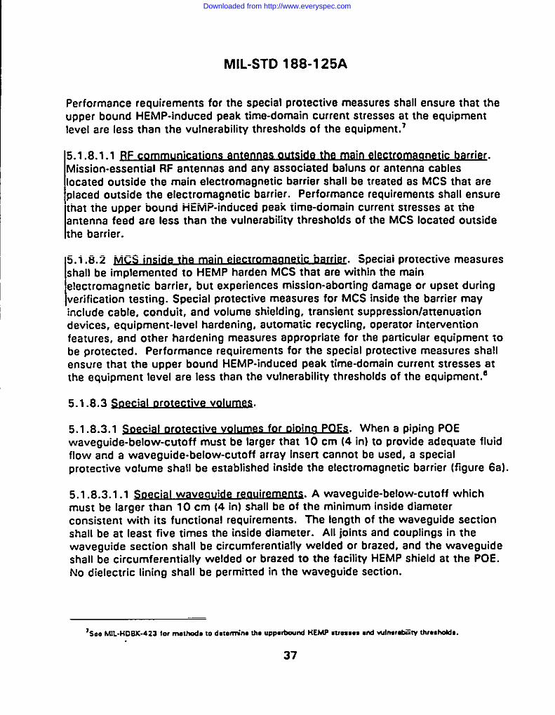
MIL-STD 188-1 25A
Performance requirements for the special protective measures shall ensure that theupper bound HEMP-induced peak time-domain current stresses at the equipmentlevel are less than the vulnerability thresholds of the equipment.’
5.1.8 .1.1~b arri~.Mission-essential RF antennas and any associated baluns or antenna cableslocated outside the main electromagnetic barrier shall be treated as MCS that areplaced outside the electromagnetic barrier. Performance requirements shall ensurethat the upper bound HEMP-induced peak time-domain current stresses at theantenna feed are less than the vulnerability thresholds of tha MCS located outsidethe barrier.
5.1.8.2 ~.. .
Special protective maasuresshall be implemented to HEMP harden MCS that are within the mainelectromagnetic barrier, but experiences mission-aborting damage or upset duringverification testing. Special protective measures for MCS inside the barrier mayinclude cable, conduit, and volume shielding, transient suppression/attenuation
devices, equipment-level hardening, automatic recycling, operator intervention
features, and other hardening measures appropriate for the particular equipment to
be protected. Performance requirements for the special protective measures shallensure that the upper bound HEMP-induced peak time-domain current stresses atthe equipment level are less than the vulnerability thresholds of the equipment.e
5.1.8.3 Oecial orowt ive v-.
5.1.8.3.1 ~ial orotect ive volumes for ~mo POfi.. .
When a piping POEwaveguide-below-cutoff must be larger that 10 cm (4 in) to provide adequate fluidflow and a waveguide-below-cutoff array insert cannot be used, a specialprotective volume shall be established inside the electromagnetic barrier (figure 6a).
5.1.8 .3.1.1 ~oec ial waveau de reou ~.i i A waveguide-below-cutoff whichmust be larger than 10 cm (4 in) shall be of the minimum inside diameterconsistent with its functional requirements. The length of the waveguide sectionshall be at least five times the inside diameter. All joints and couplings in thewaveguide section shall be circumferentially welded or brazed, and the waveguideshall be circumferentially waldad or brazed to the facility HEMP shield at the POE.No dielectric lining shall be permitted in the waveguide section.
7Seo MIL-14DSX-423 for nmIhods 10 d.lnm”.- h. uwotir’d HEMP SVMS*S ●I8I WIIW**V Vueshdda.
37
Downloaded from http://www.everyspec.com
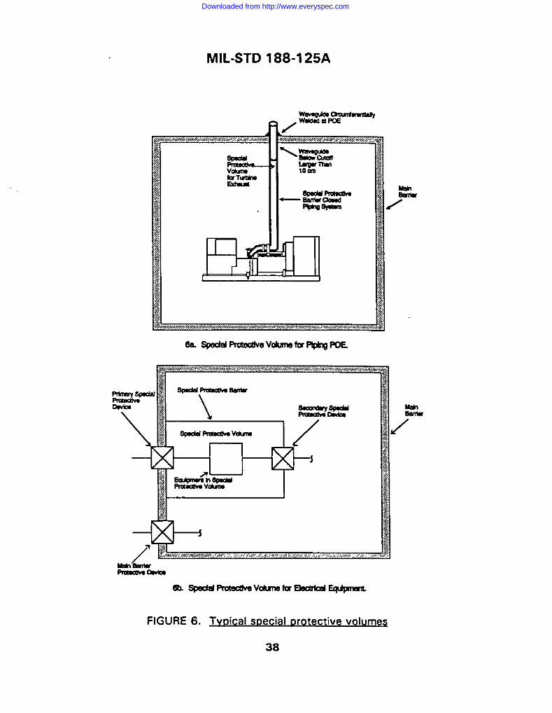
MIL-STD 188-1 25A
SS.ap3ddPr0tmNevcbmfc9P@&lgPoE
&Lafedd RuecumvOhlrallYEbarlcdG@p-mll
FIGURE 6. Tvoical sDecial Drote ctive volumes
38
Downloaded from http://www.everyspec.com

MIL-STD 188-1 25A
5.1.8 .3.l.2~ ive barrier fo. .r oloma P~. A special protective barrier
shall completely enclose piping which is protected at its POE with a waveguide-below-cutoff larger than 10 cm (4 in) inside diameter. The special protectivebarrier may be a separate shield with protected penetrations, or itmay beimplemented using the metal walls of the piping system itself (see figure 6a).Performance requirements for the special protective barrier shall ensure that thetotal shielding effectiveness, measured through the main electromagnetic barrierand special protective barrier, satisfies at least the minimum requirements shownon figure 1.
5.1.8 .3.2~t ive vo~l POES. When a main barrier
protective device cannot be designed to achieve the transientsuppression)attenuation performance prescribed for the class of electrical POE (see5.1.7) without interfering with operational signals it Is required to pass, a specialprotective volume shall be established inside the main electromagnetic barrier(figure 6b). The special protective volume shall be enclosed by a special protectivebarrier with primary and secondary protective devices as raqulred to meet theperformance requirements prescribed in this standard.
5.1.8.3.2.1- wotective ~cal PQ& A special protectivebarrier shall completely enclose wiring and equipment directly connected to aprimary special protective device’. The special protective barrier may be a separateshield with electromagnetic barrier and shall satisfy at least the requirements offigure 1.
5.1.8 .3.2.2 Primarv ~ i ive devi~ . A primary specialprotective device shall be substituted for a main barrier protective device that
cannot achieve the prescribed transient suppression/attenuation performance (see
table 1 ) without interfering with the operational signals it is required to pass. The
primary special protective device shall be designed to provide the maximumtransient suppressionlattenuation consistent with its functional requirements.When the pulse prescribed for the class of electrical POE occurs at the externalterminal (see table l), the primary special protective device shall perform itsdesigned task(s) without damage or degradation.
5.1.8 .3.2.3~ct i ive device re~ . When thecombination of the primary special protective device and the directly connectedequipment cannot be designed to achieve the transient suppression/attenuationperformance prescribed for the class of electrical POE (see table l), a secondaryspecial protective device shall be used (figure 6bl. The secondary specialprotective device shall be designed so that the total transient
39
...-—
Downloaded from http://www.everyspec.com

MIL-STD 188-1 25A
suppression/attenuation, measured through the primary special protective device,
the connected equipment, and the secondary special protective device, satisfies atleast the minimum requirements of 5.1.7 for the prescribed class of POE.
5.1.8 .3.2.4 MCS in a soecial motect ive volume. Special protective measures shallbe implemented as necessary to harden MCS in a special protective volume to theHEMP-induced signals that will occur in that volume. Special protective measuresfor MCS in a special protective volume may include cable, conduit, and volumeshielding, transient suppression/attenuation devices, equipment-level hardening,remoting sensitive circuits, automatic recycling, operator intewention features, andother hardening maasures appropriate for the particular equipment to be protected.Performance requirements for the special Protective measures shall ensure that theupper bound HEMP-induced peak time-domain current stresses at the equipmentlevel are less than the vulnerability thresholds for the equipment.d
5,1.8.4 Qualitv assurance for soecial mote ctive measu reS, Quality assurancetests shall be conducted to ensure that special protective measures comply withperformance requirements for the particular installation.
5.1.8.5 Acceptance testina for soecial orot ective measures.
5.1.8.5.1 ~s. Acceptance testing is notrequired for equipment-level special protective measures installed on MCS IAWwith 5.1.8.1, 5.1.8.2, and 5.1.8.3.2.3. HEMP hardness provided by thase specialprotective measures shall be demonstrated during the verification test program.
5.1.8.5.2 Soeciai rxotective barriers. Acceptance testing for all special protectivebarriers shall be conducted using shielding effectiveness test procedures ofappendix A, Additionally, acceptance testing for all special protective barriersrequired because of an electrical POE protective device shall include PCI IAW testprocedures of appendix B.
5.1.9 Reliabili tv and maintainability. The HEMP protection subsystem shall bedesigned and constructed to be rugged, reliable, and maintainable. Reliability andmaintainability program tasks and requirements shall be included in the facilityacquisition specifications to assure that reliability is considered in componentselections, to reduce the frequency, complexity, and costs of design-dictatedmaintenance, and to provide adequate provisioning with spare HCI andmaintenance tools and supplies.
40
Downloaded from http://www.everyspec.com

MIL-STD 188-1 25A
5.1.10 Sf@vand ~. Safaty and human engineering critaria,principles, and practices shall be applied in tha design, selection, and placement ofHEMP protection subsystem alemants. Entryways shall ba designad to
accommodate axpected traffic and shield doors shall operata simply with oparatingforcas within limits imposad by MlL-STD-l 472. Inspection covars shall badesigned for safaty and ease of removal and proper reinstallation. Electrical POEprotective devices shall provide fail-safe features, such as capacitor dischargaresistors, for protection of personnel during installation, operation, maintenance,and rapair. Radiofrequency radiation protection for personnel shall be addressedIAW DoDI 6055.11.
5.1.11 ~. The HEMP protection subsystam shall be designed andconstructed to accommodate quality assurance, acceptance and verificationtesting, and HM/HS. The facility shield shall be accessible for visual inspection atall POES. Access for pariodic shielding effectiveness measurements shall baprovidad except on the floor shield of a bottom floor and on buried facilities. Thebuilt-in shield monitoring capability shall consist of a Permanently installed largeloop or a permanently installed shield injection point system, as described inMIL-HDBK-423, or other exciter and sensor elements which will datect significantchanges in the electromagnetic barrier parformanca. Electrical POE protectivedevices shall be installed with accessible PCI drive points and maasurament points.
5.1.12 corrosion contr~. Corrosion protection measures shall be Implemented inthe design and construction of the HEMP protection subsystem. The facility shialdand POE protective davices shall be constructed with inherently corrosion-resistantmaterials or metals shall be coated or metallurgically procassad to resist corrosion.Pockets whare water or condensation can collact shall be avoided and a crawlspace shall be provided above the ceiling shield to allow inspection for roofleakage. Buried conduits or cables shall be coated with asphalt compound, plasticsheaths, or equivalent corrosion protection, and a maans for detecting Iaakage shallbe provided. Joints between dissimilar matals shall ba avoided and, whererequirad, shall be providad with corrosion preventive measures. Cathodicprotection shall be provided, where required by environmental conditions.
5.1.13 Con fiawn manaoe m. A hardness configuration managementprogram shall be implamantad %uring design and construction of the HEMP
I
protec~ion subsystem. Hardness critical items and hardness critical processes shallbe identified in the facility drawings IAW Ml L-STD-l 00, and installed hardnesscritical items shall ba distinctively marked with DD Form 2639, Hardness CriticalLabel or DD Form 2640, Hardness Critical Tag as appropriate. Facility design andinstallation changes shall be assessed for potential HEMP hardness impacts prior to
41
Downloaded from http://www.everyspec.com

MIL-STD 188-1 25A
I
approval. The affected portions of the I-IEMP protection subsystem shall be
retested when configuration changes, MI L-STD-480, occur after acceptancetesting.
5.1.14 Verification testinq. After the HEMP protection system has been acceptedand facility equipment is installed and operational, a verification test program shallbe conducted. As a minimum, verification testing shall include CW immersiontesting of the electromagnetic barrier, PCI tests at electrical POES, and additionalsite-specific tests as needed to demonstrate effectiveness of special protectivemeasures. All deficiencies identified by the verification test program shall becorrected, and retested until the required hardness is achieved.
5.1.14.1 CW immersion testinq. CW immersion testing shall be performed IAWprocedures of appendix C. At frequencies whera the measurement dynamic rangeexceeds the attenuation required by figure 1, ratios of illuminating field strangth tothe internal field measurements shall be equal to or greater than the minimumshielding effectiveness requirement. Internal field measurements shall be below theinstrumentation noise or operating signal level in frequency bands wheremeasurement dynamic range is less than attenuation requirements of figure 1.Internal current measurements, when extrapolated to threat using equationsdefined in appendix C, shall be less than 0.1 A. No interference withmission-essential communications- electronics or suppo~ equipment shall occur.
When approved by the sponsoring agency for the verification test, a thoroughprogram of shielding effectiveness measurements using procedures of appendix Aand a thorough SELDS survey IAW MIL-HD8K-423 guidance may be performed inlieu of the CW immersion test.
5.1.14.2 PCI verification testinq. PCI verification testing shall be performed IAWprocedures of appendix B. Residual internal transient stress measurements shallnot exceed maximum limits for the applicable class of electrical POE. POEprotective devices shall not be damaged by the PCI excitations. No time-urgent,mission-impacting damage or upsets of MCS shall occurs
5.1.14.3 Verification for soecial orotect ive measures. Site-specific procedures forverification of special protective measures shall be developed based upon testapproaches of 5.1 .14.3.1 and 5.1.14.3.2. The verification testing shalldemonstrate that HEMP-induced electromagnetic stresses resulting from facility
%hs detonninati.n whether an .bs.wed interruption or upset is mis=i.wabomha is the rnsm.rnbilitv of the operational
authority for the facility.
42
Downloaded from http://www.everyspec.com

MIL-STD 188-1 25A
II
II
exposure to the threat environment of DoD-STD-2169 will not cause time-urgent,mission-impacting damage or upsets.’
5.1.14.3.1 Verific ation of soec ial orotect ive me~res fo r MC~. Verificationtesting for MCS hardened with special protactive measures shall generally includecoupling measurements and PCI procedures. Thecoupling test shall bethreat-relatable such as by pulse field illumination, PCI, or CW immersion (seeappendix). MCScable currents shall be measured andextrapolated to the HEMPEnvironment Criteria [DoD-STD-2169 (current version)].
Long conductors that connect to the MCS and are directly exposed to the HEMP
environment shall be PCI tested with injected pulses of the amplitudes andwaveforms prescribed in appendix B.
Cables that connect or are internal to the MCS and are not directly exposed shallalso be PCI tested. The injected pulse characteristics shall comply with one of thefollowing requirements:
a. Amplitudes equal to the upper bounds of the HEMP4nduced currentstresses and waveforms similar to the measure data. For purposes of thisstandard, the upper bound shall be equal to 10 times the extrapolated coupling testresults.
b. Amplitudes and waveforms prescribed in appendix B for the applicableclass of electrical circuit.
These verification test excitations shall not cause time-urgant, mission-impactingdamage or upset of MCS.7
5.1.14.3.2 Verification of soecial oro~ “ve barr~. Verification of specialprotective barriers shall include PCI testing of all electrical POES which penetrateinto the special protective volume from outside the protective volume. Amplitudesand waveforms of the injected pulses shall be as prescribed in appendix B. Inaddition to functional observations and measurements required by 5.1.14.3.1,residual internal stresses shall be measurad on conductors which penetrate fromthe special protective volume into the protected volume. Responses measured attest points within the protected volume shall not exceed maximum allowable limits,and the test excitations shall not cause time-urgent, mission-impacting damage or
upset of MCS.
43
Downloaded from http://www.everyspec.com

MIL-STD 188-1 25A
5.1.15 HM/HS woaram reauirement$ Logistics support analysis for the HEMPprotection subsystem shall be performed IAW MIL-STD-1388-1 during the facilityacquisition phase. The logistics SUPPO~ analysis shall define the HEMP protectionsubsystem HM/HS requirements, supply support requirements, trainingrequirements, and technical data requirements.
5.1.15.1 HS/reverific ation test orocedure$. Detailed HS/reverification testprocedures for the HEMP protection subsystem shall be developed and used. TheHS tasks shall be performed on a periodic basis as described in the HM/HSprogram. The reverification test results shall be correlatable to verification test
~ results and shall have the same pass/fail criteria. The procedures shall identify thetests to be performed, test equipment requirements, safety precautions, and other
I relevant information.
5.1.15.2 ~s. Detailed procedures formaintenance and inspection and for repair and replacement of HEMP hardnesscritical assemblies or items shall be provided. Maintenance and inspectionprocedures shall be designed to be implemented at the organizational maintenancelevel and shall identify the tasks to be performed, frequency of performance,pass/fail criteria where applicable, safety Precautions, and other relevantinformation. Repair and replacement procedures shall identify the tasks to beperformed, hardness assurance requirements including pass/fail criteria, safetyprecautions, and other relevant information.
5.1.15.3 ~s. A parts list of the installed HEMP hardnesscritical assemblies or items and lists of recommended organizational HEMPprotection subsystem spare parts, repair parts, supplies, special tools, and specialtest equipment shall be provided. The lists shall identify the nomenclature ordescription of each item, the manufacturer and manufacturer’s part number, thefederal stock number when assigned, the required quantity, and other relevantinformation. All hardness critical assemblies, items, cables, etc. shall be identifiedusing either DD Form 2639, Hardness Critical Label, or DD Form 2640, HardnessCritical Tag as appropriate.
5.1.15.4 Trainino requirement.s. Training requirements for personnel assigned to aHEMP-hardened facility shall be defined. As a minimum, the training program shallinclude organizational HEMP awareness training for all site personnel and classroomand on-the-job training for HM/HS maintenance personnel. Training materials shallbe provided for all training, MlL-STD-l 379D, to be administered at theorganizational level.
I
44
Downloaded from http://www.everyspec.com

MIL-STD 188-1 25A
5.1.15.5 Technical m. A HEMP protection subsystem technical manual shall beprovided. As a minimum, the technical manual shall include the following:
I a. HEMP protection subsystem description and principles of operation.
b. Maintenance and inspection procedures, repair and replacementprocedures, and hardness surveillance test procedures.
I c. Supply support requirements.
I d. Training requirements.
5.1.15.6 Delivery. The HEMP protection subsystem technical manual shall bedelivered with the facility. Recommended organizational I+EMF’ spare Parts, rePair
parts, supplies, special tools, special test equipment, and training materials shall
also be delivered with the facility.
5.1.15.7 ~. HEMP protection subsystem preventive maintenance,inspection, and Hardness Surveillance [HS)/reverification testing shall be performed
IAW the technical manual. Corrective maintenance shall be performed if the HEMP
protection subsystem performance degrades below the minimum requirements of
this standard. Hardness Surveillance (HS)/reverification testing shall be performed
at intervals not exceeding seven years.
45
.. ..—
Downloaded from http://www.everyspec.com
MIL-STD 188-1 25A
6. NOTES
(THIS SECTION CONTAINS INFORMATION OF A GENERAL OR EXPLANATORY
NATURE THAT MAY BE HELPFUL, BUT IS NOT MANDATORY.)
6.1 Intended use. The standard contains minimum requirements and designobjectives for HEMP protection of fixed ground-based facilities which performcritical, time-urgent C’1 missions. The purpose is to standardize design,construction, and test of HEMP protection subsystems for these facilities and tothereby assure the quality and durability of the protection.
6.2 Subiect term lkev word) Iistinq.
Continuous wave (CW) immersionElectrical surge arresterElectromagnetic barrierFacility HEMP shieldHardeningHardness verificationLow risk HEMP protectionMission-critical systemsNuclear survivabilityPOEProtection device, POEPulsed current injectionShielding effectivenessSpecial protective measuresSurvivability/vulnerabilityTransient suppression/attenuation deviceWaveguide-below-cutoff
6.3 Chancres from mevious issue. The margins of this standard are marked withvenical lines to indicate where changes, additions, modifications, or correctionsfrom the previous issue were made. This was done as a convenience only and theGovernment assumes no liability whatsoever for any inaccuracies in thesenotations. Bidders and contractors are cautioned to evaluate the requirements ofthis document based on the entire content irrespective of the marginal notationsand relationship to the last previous issue.
46
Downloaded from http://www.everyspec.com

MIL-STD 188-1 25AAPPENDIX A
SHIELDING EFFECTIVENESS TEST PROCEDURES
10. GENERAL,
10.1 -. This appendix is a mandatory part of tha standard. The informationcontained herein is intendad for compliance. This appendix establishes proceduresfor measuring the shielding effectiveness of the electromagnetic barrier required forlow-risk HEMP protection of critical ground-based facilities with time-urgentmissions. The procedures are applicable for testing othar HEMP-hardened facilities,when specified by the procurement documentation.
10.2 ~. These procedures shall be used for shielding effectivenessacceptance testing of tha facility HEMP shiald and aperture POE protectivetreatments, as required by the DHAILED REQUIREMENTS of MlL-STD-l 88-125A.The procedures shall also be performed for acceptance of repairs or installations ofnew POE protective devices after construction acceptance, except that only areasaffected by the repair or installation shall be testad. Shielding effectivenessmeasurements may also be conductad as part of tha verification test program.
20. REFERENCED DOCUMENTS.
20.1 Government doc umen~. The following documents form a pafl of thisappendix to tha extent specified:
DI-NUOR-80928 Nuclear Survivabili~ Tast Plan
DI-NUOR-80929A Nuclear Survivability Test Report
DNA-EMP-1 Electromagnetic Pulse (EMP) Security Classification Guide(U) (document is classified S-RD).
(Copies of specifications, standards, handbooks, drawings, and publicationsrequired by contractors in connection with specific acquisition functions should beobtained from the contracting activity or as directed by the contracting officer. )
*HEW%tiqL18 teat procodwos we tarnpomfllv included ● aormndices to hUL-SID 188. 12S: it is intended h: th.s.
procedures will ullinu:alv b. Pfonndaatod ● sevwol. 8tandard8 wtsldo al III* MIL-STD 188-s.Iie9.
47
Downloaded from http://www.everyspec.com

MIL-STD 188-1 25AAPPENDIX A
20,1.1 Standards. The following document forms a Part of this appendix to theextent specified:
IEEE-299-1991 IEEE standard for Measuring the Effectiveness ofElectromagnetic Shielding Enclosures.
(Applications for copies should be addressed to the institute for Electrical and
Electronics Engineers, 445 Hoes Lane, post Office Box 1331, Piscataway NJ08 B55-1331.)
30. DEFINITIONS.
30.1 Shieldina effectiveness (SE~. (at a test area) For the purposes of thisprocedure, the ratio, expressed in decibels (dB), of the received signal when thereceiving antenna is illuminated by electromagnetic radiation in the test calibrationconfiguration (no shield present) to the received signal through the electromagnetic
barrier in the test measurement configuration. Assuming that antenna voltage isdetected
HSE-2010!+m
where V~ is the measured signal at the test area and V, is the calibration signal
at the same frequency and transmitting antenna polarization. Shieldingeffectiveness values are test method-dependent and different values may beobtained when time-domain or other frequency-domain measurement techniquesare used.
40. GENERAL REQUIREMENTS
40.1 General. This HEMP shielding effectiveness test method is similar to lEEE-STD-299-1991 except that the requirements have been modified to evaluate the barrierperformance over a narrower frequency range using a minimum set of test points and
: test frequencies. A transmitting antenna is placed on one side of the electromagneticbarrier in the center of each test area. The receiving antenna is centered on the testarea at the opposite side of the barrier to obtain a stationary measurement.Additionally, the receiving antenna is swept over the entire test area and rotated inorientation until the maximum received signal strength is detected. Selection of test
48
Downloaded from http://www.everyspec.com

MIL-STD 188-1 25AAPPENDIX A
areas, test frequencies, and polarizations of the transmitting antennas are defined in
this appendix.
40.2 ~ These procedures define shielding effectiveness, as used in MIL-STD-188-1 25A. The purpose of the measurements is to obtain shielding effectiveness datafor demonstrating compliance with facility shield and aperture POE treatment
performance requirements established by Ml L-STD-l 88-1 25A.
40.3 HEMP orot~. The shielding effectivenessacceptance test should be conducted near the conclusion of the construction contract,when the following prerequisite conditions are mat. The facility shield assembly shallbe completed. All POES and their POE protective devices, required as part of theconstruction work, shall be installed and in a normal operating condition. Internal andexternal wiring to conductive POE protective devices, if provided under theconstruction contract, shall be in place and connected. Penetrating fiber optic cables,if provided under the construction contract, shall be installed. All interior equipmentand finish work under the construction contract shall be completed. Installedequipment may be either operating or nonoperating. A visual shield inspection shall beperformed before starting the measurements to assure that these configurationrequirements have been met.
When these shielding effectiveness measurements are conducted as pan of theverification test program, the facility shall be in a normal operating configuration andshould be performing actual or simulated mission functions. Tha HEMP protectionsubsystem shall be intact.
40.4 pnalvsis reau remen~.i Thare are no pretest or post-test analyses required forthese procedures.
40.5 ~iament reau ir~. Test equipment required for shieldingeffectiveness measurements is identified in table Il.
40.6 ~ analvs is and risk. Since tha electromagnetic barrier mustremain intact during conduct of the shielding effactivaness measurement sequence,and use af electrically noisy equipment must be restricted, construction activity orunusual operations (facility modification, maintenance) may be affected. Radiatedsignal levels are low and present no hazard to equipment, but frequency adjustmentsmay be required to avaid self-interference with nearby facilities. Normal electricalsafety precautions apply.
49
Downloaded from http://www.everyspec.com

TABLE Il.
MIL-STD 188-1 25AAPPENDIX A
Shieldinq effectiveness tes t eauioment requirements
I Equipment Characteristics
llOsciNator(s.) 15-30 kHz, 300.500 kHz, 1-20 MHz, 10+3-400 MHz, 900-t 000 MHz
Power Amplifier(s) 15.30 kHz, 300-5CK3 kHz, 1-20 MHz 1CG400 MHz, 900-1 (XXI MHz,Dower outout as rewired for dmemic range
Preamplifier(s) 15-30 kHz, 3CG500 kHz, 1-20 MHz, 100-40+3 MHz, 900-1000 MHz,amplification and noise figure as required for dynamic range
Receiver(s) and 15-30 kHz, 300-500 kHz, 1-20 MHz, 100400 MHz, 900-1000 Mt!z
Spectrum Analyzer(s)
Antenna Xit’ 15-30 kHz, 300-500 kHz, 1-20 MHz, 100-400 MHz, 900-1000 MHz
Miscellaneous Cables As requiredand Attenuators
1Any antennas which radiate 81 the pmsaii.d h.qwnd.8 may b. ttsad. Howovar.mt.nnm that mq.lre I.rua dear .pma h
the direction of wave propagation shall ..1 b. umd whom dear ■p.rn h Ilrnimd for t8sdna. Saampl.. of .ueh am.n.m we towperiodic dipole and clrcularlv polarized c.nl.al epirnl antonn.s. Pro.. durs@ am mift.n euumlng use of dlp.al. or ap.nur.nnmnnn. f.. plane wave meaaur. me”m and loop ant.nnm for magnetic field m.murnnwnm.
40.7 Test D Ian and mocedure~. A shielding effectiveness test plan and detailed testprocedures shall be prepared. These may be combined in a single document or twoseparate documents may be used. As a minimum, the documentation shall containthe following information:
a. A statement of test objectives.
b. Facility identification and description.
c. Plane wave test area identification. The entire surface (including the floorwhen both sides of the shield are accessible) of the electromagnetic barrier shall bedivided into numbered plane areas not greater than 2.5m x 2.5m (8.2 ft x 8.2 ft), asillustrated by the example in figure 7. A plane wave transmitting antenna locationexists at the center of each area. A list of POES, by test area, shall be included.
d. Low frequency magnetic field test area identification. Each 2.5m x 2.5mplane wave test area which contains a POE shall also be designated as a magneticfield test area. Additional magnetic field test areas shall be chosen to sumey theentire surface of the electromagnetic barrier in sections not greater than 7.5m x 7.5m
50
Downloaded from http://www.everyspec.com
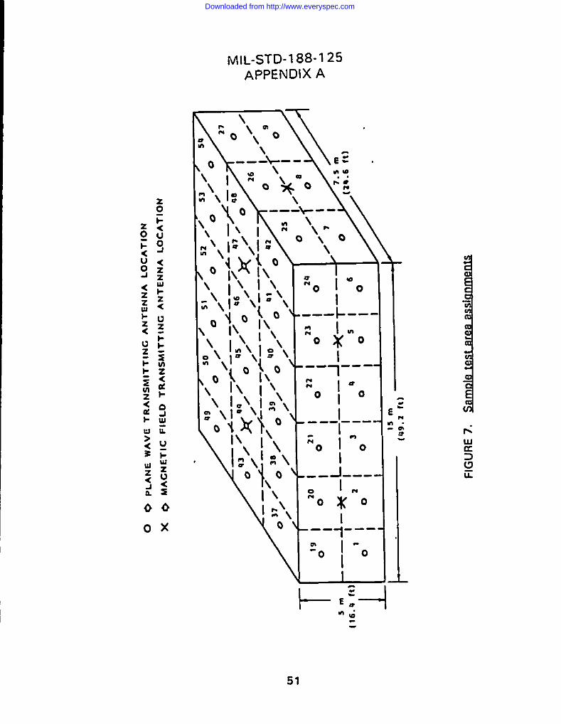
MIL-STD-1 88-125APPENDIX A
~’\l;\:- \
\
\
I1---- ---
I---—- -z +
-1-- ---0 Im“QXQ
I1---- --
‘o I -0I
-
1--..
E:—
m;
51
Downloaded from http://www.everyspec.com

MIL-STD 188-I’25AAPPENDIX A
(24.6 ft x 24.6 ft). A magnetic field transmitting antenna location exists at the center
of each test area.
e. Electric field test area identification
documentation).
(when required by the procurement
f. Identification of test frequencies.
9. Test equipment identification by manufacturer, model, and serial number.
h. Any deviations from requirements of this appendix,
i. Procedures for marking, repair, and retest of defects.
i. Data management [including calibration and measurement data quality
control procedures, data acceptability criteria, preservation of data records, and
pass/fail criteria).
k. Safety.
1. Security. (see 40.9)
m. Test schedule (including priority of measurements).
Data item description DI-NUOR-80928, “Nuclear Survivability Test Plan, ” should beused.
40.8 Test report requirements. A shielding effectiveness test report shall beprepared. As a minimum, the repofl shall contain the following information:
a. Facility identification and test plan reference.
b. A discussion of any deviations from the test plan and requirements of this
appendix.
c. Test calibration and measurement data (figure 8 illustrates a typical data
sheet).
d. Pass/fail conclusions.
Data item description DI-NUOR-80929A, “Nuclear Survivability Test Report,n should
be used.
52
Downloaded from http://www.everyspec.com

SH
IEL
DIN
GE
FF
EC
TIV
EN
ES
SD
AT
AS
HE
ET
Fac
ility
:T
est
Dat
e:In
spec
tio
n:
Tes
tTy
peof
Test
Ols
tanc
ofro
mTV
Peof
Calib
ratio
nM
easu
red
Shle
ldln
gSh
leld
lng
Alan
(Pla
neW
ave
Freq
uenc
y/An
tenn
ato
Mea
sure
men
tsi
gnal
(Vol
Sign
al(V
ml
Effe
cllv
enes
sEl
Iect
ivan
ess
Num
ber
orM
agne
tic)
Pola
rizat
ion
Shie
ldW
all
(Sta
tiona
ryor
(Vor
dBVl
or{V
or20
log
(v./v
m)
Requ
irem
ent
Swep
t}dB
V)or
dBV.
-d
BV-I
(dill
Pass
rFal
l
.--.
...
.
>LN u-l
Sig
nat
ure
Tit
lean
dO
rgan
izat
ion
FIG
UR
E8.
sam
ole
wIr
lirm
effe
cti
mes
sd
ata
shee
tv
Downloaded from http://www.everyspec.com
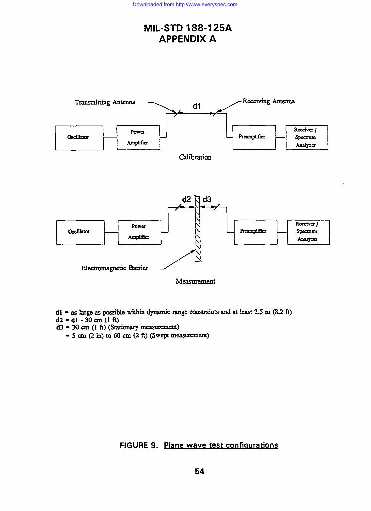
MIL-STD 188-1 25AAPPENDIX A
TransmittingAnte.ma
~R”i’g-CamJradon
d2 7 d3
\\
Cbdn@mIsw+a \
\\ - tm
11.a&crI
.4mplllm\
ElectromagneticBanic.r
dl - aslargeaspsiik wi!hindynamicrangewmsuainuand at least 2.5m (8.2ti)dZ-dl-30cm(lft)d3 -30 an (1ft)(sIariamuy~)
-5cm(2in) L060cln(2ft)(swept~-)
FIGURE 9. plane wave test configurations
54
Downloaded from http://www.everyspec.com
MIL-STD 188-1 25AAPPENDIX A
40.9 Data classifi~ “ n. Test data may be classified. DNA-EMP-1 and theclassification guide for the specific facilitY or Wstem should be consulted for guidance.
50. DETAILED REQUIREMENTS
50.1 Plane wave SE measurements.
50.1.1 Pla ne wave data reau irem~. For each plane wave test area (see 40.7c),
eight shielding effectiveness measurements shall be made. Stationary and swept-in-
space measurements shall be made at two frequencies for each of two transmitting
antenna polarizations, as follows:
a. Frequencies - One frequency in the ran9e of 100-400 MHz and onefrequency in the range of 900-1000 MHz.
b. Antenna polarizations - Dipole (Or antenna aperture) parallel to the test area
surfaca in two orientations at 90 degrees to each other and parallel to the principlesaams.
50.1.2 Plane wave ca Iibration arocedure. Plane wave calibration for each frequency
and transmitting antenna polarization shall be Performed IAW figure 9. Thetransmitting and receiving dipole antennas shall be Parallel to each other (or apertureantenna planes parallel to each other). The distance between antennas shall be as
large as possible, within dynamic ran9e constraints. but shall be at least 2.5m (8.2 ti).The receiving antenna position shall be varied by *30 cm (-1 ft) from its nominallocation to ensure that it is not located at a minimum of the radiation pattern. Testequipment shall be chosen to provide a dynamic range at least 20 dB in excess of theshielding effectiveness requirement at the test frequency.
During calibration, no equiPment or other electromagnetic reflectors (exceptground) shall be closer than three times the antenna separation. The antennas shall beat least 1.5-2 m (6.6 ft) above ground.
The received signal strength for each frequency and transmitting antannapolarization shall be recorded as the calibration signal ( v=) for that configuration.
50.1.3 Plane wave measu rement aroce$.uu2. Plane wave shielding effectiveness
measurements for each test area and at each required frequency and transmittingantenna polarization shall be performed as shown in figure 9. Identical equipment,antennas, cables, and eqUiPment senin9s (excePt attenuator seTtings) shall be used inthe calibration and measurement sequences.
55
Downloaded from http://www.everyspec.com

LMIL-STD 188-125A
E APPENDIX At-3u
I.u
3__3
n II==1.Ll<muzLuw-1u
---———-—-—-—-—-—-\
\
\
\
\
-0
a
-0
m0
x—
-.
___-- ———--— ——— ——— ——— - >----
\
\: “0
—x
I I I I I I 1 1 1 I“a ~
Oaoo 00 ~00--Oom E Zmw .%
--
(9P) 3S - SS3N3A1133+33 9NIC1131HS
56
Downloaded from http://www.everyspec.com

MIL-STD 188-1 25AAPPENDIX A
The transmitting antenna normally should be placed outsida the electromagneticbarrier and it shall be centered on the test area. Tha transmitting dipole axis (oraparture antanna plane) shall be parallal to the test area sutiace and parallel to one oftha two principle wald saam directions. Tha distance from the transmitting antanna tothe test araa surface shall be 30 cm (1 ft) lass than the separation at which calibrationwas performed.
Tha raceiving antanna should normally be inside the barriar. To obtain thestationary maasuremant, the recaiving antenna shall be centered on tha test area andthe dipole axis (or aperture antenna plane) shall be parallel to the transmitting antennaaxis (or plane). Distance from the recaiving antenna to the test area surface shall be30 cm (1 R). The received signal strength shall be recordad as the stationarymaasurad signal ( V,) for that test area, frequency, and transmitting antennapolarization.
To perform the swapt-in-space measurement, the receiving antenna shall beswapt over the entire test area at distancas of approximately 5 cm (2 in) to 60 cm (2ft) from the test area surfaca and shall be rotated in orientation until a maximumreceived signal is obtained. The maximum received signal strength shall be recordedas tha swept measured signal ( Vm)for that test araa, frequency, and transmittingantenna polarization.’”
50.1.4 mw ave -l fail cri~. The pass/fail criteria for plane wave shieldingeffectiveness are shown as a function of fraquency by figure 10.
50.2 LOw fr”eouancv maanetlc fIeld shie~ iveness m~u ement~r
50.2.1 Jvlacinatic field @ reou r~.i For each 2.5 m x 2.5 m magnatic fiald testaraa (sac 40.7dl, twelve shielding effectiveness maasuremants shall be made.Stationary and swept measurements shall be mada at three frequancias for each oftwo transmitting antenna polarizations, as follows:
a. Frequencies. One frequency in the range of 10-30 kHz, and one frequencyin the ranga of 300-500 kHz, and one frequancy in the range of 1-20 MHz.
b. Antenna polarizations - Plane of the loop antenna normal to the test araa
surface in two orientations at 90 degrees to each other and parallel to the principleweld seams in the shiald.
‘%’tw. m. test am. .onmim a. CPmw. or cmd.c!iv. POEwhkh r..auhs . wocid pr.t.cd.. wabun. imid. rhod.ctmmagn.dc barrier, the r.coitiw ●n:em must also be sweP: ovw the .ntif* wtw surfaca of the 8Pecia! PMteCdve
barrier. at distwoc8a from wrmmdmaletv 5 cm to 60 cm frwn the bw!i.t SUIIU*. ●d mlmd i. orientation. Pumtfail aitetiar~, tiesa redinoa mm h s-* ●s rho psxsl failcnmda 10, otiu stiakllno *ff.ctiwm99 moacwana.ts.
57
Downloaded from http://www.everyspec.com

MIL-STD 188-125AAPPENDIX A
For each 7.5 m x 7.5 m magnetic field test area, six shielding effectivenessmeasurements shall be made. Stationary measurements shall be made at threefrequencies for each of two transmitting antenna Polarizations, as described above.
50.2.2 Maanetic field calibration Droced ure. Magnetic field calibration for eachfrequency and transmitting antenna polarization shall be performed IAW figure 11.
The loops of the transmitting and receiving antennas shall be in the same plane. Thedistance between antennas shall be as large as possible, within dynamic rangeconstraints, but shall be at least two IOOP diameters and at least 1.25 m (4.1 tt). Thereceiving antenna position shall be varied by *3O cm (1 ft) from its nominal locationto ensure that it is not located at a minimum of the radiation pattern. Test equipmentshall be chosen to provide a dynamic range at least 20 dB in excess of the shieldingeffectiveness requirement at the test frequency.
During calibration, no equipment or other electromagnetic reflectors (exceptground) shall be closer than three times the antenna separation. The antennas shall beat least 1 m (6.6 ft) above ground.
The received signal strength for each frequency and transmitting antennapolarization shall be recorded as the calibration signal ( V=) for that configuration.
50.2.3 Maanetic field measurement orocedure. Magnetic field shielding effectivenessmeasurements for each test area and at each required frequency and transmittingantenna polarization shall be performed as shown in figure 11. Identical equipment,antennas, cables, and equipment settings (except attenuator settings) shall be used inthe calibration and measurement sequences.
The transmitting antenna shall normally be placed outside the electromagneticbarrier, and it shall be centered on the test area. The plane of the transmitting loopantenne shall be normal to the test area surface and parallel to one of the twoprincipal weld seam directions. The distance from the transmitting antenna to the testarea surface shall be 30 cm (-1 ft) less than the separation at which calibration wasperformed.
The receiving antenna shall normally be inside the barrier. To obtain thestationary measurement, the receiving antenna shall be centered on the test area andits loop shall be in the same plane as that of the transmitting antenna. Distance fromthe receiving antenna to the test area surface shall be 30 cm (1 ft). The recaivedsignal strength shall be recorded as the measured signal (%) for that test araa,frequency, and transmitting antenna polarization.
58
Downloaded from http://www.everyspec.com

MIL-STD 188-1 25AAPPENDIX A
Tm!datng AnImM
kd’fnlGdl19m *
1
Calii
dl-Lmp Dhumicrd2 - A# large u pil~ within -C nlngc ,ccm=?@%
indulcsst2xdlarlXm(4.lfi) WhuhcWrl.llqcl
d3-dz-3oalIOn)d’$-mcsl (lfl)(sullkmym=suM=O
- Sanoln)mdOcmoft)(s.$@ ==sm==@
FIGURE 11. ~f COnfiaurat ions
59
Downloaded from http://www.everyspec.com

MIL-STD 188-1 25AAPPENDIX A
To perform the swept measurement, when required, the receiving antenna shall
be swept over the entire test area at a distance of approximately 5 cm (2 in) to 60 cm
(2 ft) from the test area surface and shall be rotated in orientation until a maximum
recaived signal is obtained. The maximum received signal strength shall be recordedas the swept measured signal [ Vm) for that test area, frequency, and transmittingantenna polarization.e
60
50.2.4 Maanetic field oass/fail criteria. The pass/fail criteria for magnetic fieldshielding effectiveness are shown as a function of frequency by figure 10.
Downloaded from http://www.everyspec.com

Ml L-STD-l 88-1 25AAPPENDIX B
PULSED CURRENT INJECTION (PCI) TEST PROCEDURES1l
10. GENERAL.
10.1 &Q.Q& This appandix is a mandatory part of tha standard. The informationcontainad herain Is intanded for compliance. This appendix establishes PCI testprocedures for electrical POE protective devices required for low-risk HEMPprotection of critical ground-based facilities with time-urgant missions. Theprocedural are applicable for testing other HEMP-hardaned facilities, whenspecified by the procuramant documentation.
10.2 ~oolicat ionS. These procedures shall be used for acceptance testing afterconstruction of the HEMP protection subsystem and for verification testing ofelectrical POE protective treatments after the facility is completad and operational,as required by DETAILEO REQUIREMENTS of MIL-STD-188-1 25A.
20. REFERENCED DOCUMENTS.
20.1 @vernment ~. Tha following documant forms a part of thisappendix to the axtent specifiad:
DI-NUOR-80928 - Nuclaar Survivability Tast Plan
01-NUOR-80929A - Nuclear Survivability Test Repom
DNA-EMP-l - Electromagnetic Pulse (EMP) Security ClassificationGuide (U) (document is classified S-RO)
(Copies of specifications, standards, handbooks, drawings, and publicationsrequired by contractors in connection with specific acquisition functions should beobtained from the contracting activity or as directed by the contracting officer. )
30. DEFINITIONS.
30.1 -. Scalar quantities which characterize the featuras of a complicatedwaveform. Norms usad as pass/fail criteria for PCI tast residual internal stresses
‘ ‘U EMPUtiqu. t.st D*OCMIUI.Sara tampordy Indudod ss WPW9JICOS to MfL-SIO 1SE-1 15A: it 1. int.ndti ttw: th...
procuf.ral will uftimatdv be PIC.MUIWM ●s 88Pmato mandards oulsidm of the MIL-STO 1SS.s.4...
61
Downloaded from http://www.everyspec.com

MIL-STD-188-125AAPPENDIX B
are peak current, peak rate of rise, and root action. These quantities apply to shortpulse only.
30.2 ~. The maximum absolute value of a current waveform,
/(t), expressed in units of amperes, measured from time t = 0 to t = 5 x 10⁻³ s.
30.3 Peak rate of rise norm . The maximum absolute value of the first derivativeof a current waveform /(t) with respect to time, dVdt expressed in units of amperes
per second, measured from time t = O to t = 5 x 10⁴ s.
30.4 Root action. The root action norm of a current waveform l(t), in units of
amperes--, is defined by the equation
where t = O at the start of the PCI drive pulse.
40. GENERAL REQUIREMENTS.
40.1 General. PCI acceptance testing is used to demonstrate that electrical POEprotective devices, as-installed, perform lAw MlL-STD-l 88-1 25A transient
suppression/attenuation requirements. PCI verification testing confirms the
transient suppression/attenuation performance in operational circuit configurations
and demonstrates that MCS are not damaged or upset by residual internal transient
stresses.
The test method couples threat-relatable transients to penetrating conductorsat injection points outside the electromagnetic barrier. Injections in both commonmode (all penetrating conductors of a cable simultaneously driven with respect toground) and individual wire-to-ground configurations are required. For purposes ofthis procedure, ground is a point on the facilitv HEMP shield in the vicinity of thePOE protective device under test. Residual internal responses are measured, andoperation of the MCS is monitored during the verification test to determine ifmission-impacting damage or upsets occur.
The required tests are performed on each penetrating conductor and cable,RF antenna shield, and conduit shield. Simultaneous injection of all electrical POE
protective devices, if practicable, is desirable for verification testing.
62
Downloaded from http://www.everyspec.com

MlL-STD-l 88-1 25AAPPENDIX B
40.2 ~.
40.2.1 of PCI amnce Iw. The purposes of PCI testing, as anacceptance test procedure, are as follows:
a. To measure the performance of as-installed conductive POE protectivedevices.
b. To demonstrate through post-test inspection, surge arrester performancechecks, and response data analysis that the protective devices will not be damagedor degraded by thraat-relatable transients.
c. To identify defective devices or faulty installation practices, so thatrepairs or replacements can be made.
40.2.2 &UZQSX of PCI ve 1~.. . .
r The purposes of PCI tasting, as patlof a verification test program, are as follows:
a. To measure the performance of conductive POE protective devices inoperational circuit configurations.
b. Todemonstrate, through post-test inspection, surge arrester performancechecks, and response data analysis, that the protective devices will not bedamaged or degraded bythreat-relatable transients.
c. To identify defective devices or faulty installation practices, so thatrepairs of replacements can be made.
d. To characterize the residual internal transient stresses.
e. To demonstrate that residual internal transient stresses will not causemission-impacting damage or upsets of the MCS in its various operating states,
f. To provide data for HEMP hardness assessment of the facility andbaseline data for the HM/HS program.
40.3 HEMP ~.
40.3.1 Pcceotance test ~.. .
PCI testing for acceptance isperformed after the POE protective devices have been installed in the facility. Theelectromagnetic barrier is not required to be complete, but it must be recognized
63
Downloaded from http://www.everyspec.com

MIL-STD-188-125AAPPENDIX B
that an incomplete barrier may result in degradations of the POE protective device
performance and the instrumentation signal-to-noise ratio. Equipment which, in thefacility operation, will electrically connect to the POE protective device under test isnot required to be powered or installed.
40.3.2 Verification test fa cilitv configuration. When PCI verification testing isconducted, the facility shall be in a normal operating configuration and shall beperforming actual or simulated missions. The HEMP protection subsystems shall beintact. Equipment which electrically connects to the POE protective device undertest shall be powered and operating, except as otherwise specified in thisprocedure.
40.4 Pretest analvsis reauirement~. There are no pretest analyses required for PCIacceptance testing. Pretest analysis for pCl verification testing shall be performedto determine operating states in which the MCS will be tested. An equipmentshould be tested in multiple states when the switching produces significantlydifferent propagation paths for the residual internal transient, significant changes inthe equipment vulnerability threshold, or significant changes in the function beingperformed. A mission-essential transceiver, for example should be tested in atleast two states -- transmitting and receiving -- and a digital interface should betested in both the low and high signal states.
40.5 Test eauioment reouirements. Test equipment required for PCI testing isidentified in table Ill. Current injection pulse generators for all POES except RFsignal line POES are defined as Norton equivalent generators. Therefore, pulsegenerator requirements are defined in terms of short circuit current and sourceimpedance. Short circuit current is defined as current driven through a short circuitconnected to the generator output. Source impedance is defined to be thegenerator peak open circuit voltage divided by the peak short circuit current. RFPOE current injection pulse generators are defined in terms of current delivered atthe external terminal of the POE protective device.
40.6.1 ~t. When PCI testing is performed as anacceptance test procedure, the electromagnetic barrier must remain reasonablyintact, such that POE protective device performance and instrumentation signal-to-noise ratio are not excessively degraded, and use of electrically noisy equipmentmust be restricted in order to achieve the required measurement sensitivity.Construction activity may, therefore, be affected.
64
Downloaded from http://www.everyspec.com

MIL-STD-188-125AAPPENDIX B
40.6.2 ~. During PCI verification testing, the barrier mustremain intact and use of electrically noisy equipment which is not part of thenormal site equipment complement must be restricted; unusual operations (facilitymodification, maintenance) may be affected. Mission operations can continuenormally, except as follows:
a. The circuit and POE proactive davice under test may ba unavailable fornormal use; it may be nacassary to disconnect unprotected aquipment outside thebarrier, and the circuit may be periodically deenargized.
b. A special sequenca of activltias may be required so that tha circuit andfacility can ba tasted in their various operating states.
40.6.3 ~. PCI tasting requires application of high voltages and large currents.Special high-voltage electrical safaty precautions apply. Because of tha highinjection levels, the risk of POE protective devlca or equipmant damage cannot becompletely eliminated. However, the procedures are designed to minimize this risk.
40.7 Test DIan and orocedu re~.
40.7.1 ~nce ~. A comprahansive, site-specific tast plan anddetailed test procedures for PCI acceptance testing shall be prepared. These mayba combined in a singla document or two saparate documants may be used. As aminimum, the documentation shall contain the following information:
a. A statement of the test objectives.
b. Facility identification and description (including a site plan, floor plan oftha shielded volume, list of shiald POES, and a description of the HEMP protectivesubsystems).
Identification of circuits and POE protective devices to be tested(inclu;ing circuit functions and manufacturers’ data shaets and specifications forthe protective devicas).
d. Identification of test points and injection levels (see table IV).
e. HEMP simulation and data acquisition equipment description (includingmanufacturer, modal and serial numbars, characteristics, and detailed calibrationprocedures).
65
Downloaded from http://www.everyspec.com

MIL-STD-188-125AAPPENDIX 8
TABLE Ill. PCI test eauiDment requirements
2 ‘ ‘honhse
Characteristics
Intanndiat. Pulse’ Long pulse’
Fulsn Gen.r.:om’ Up to 8000 A shorn circuit Up m S00 A short circuit Up to 200 A shorf circuit
currant, double axpononfhl current. source impedance c“rr.nt, source impedanc.vm”llfcvml, ,0”,.0 at least 10 D, doubt. .; Imst 50, doubleImpedance m least 600, exponential waveform exponential wmmfonmm-d damped sinusoidalwaveform
Current Sensors 10 Khz-750 MHz, dc -10 MHz, dc -10 kHz,(Injected Transient] &8000 A 0+00 A O-2(M A
Current Sensors 100 Hz-750 MHz. O-l W A, do -10 MHz,
(Residual Internal
de -10 kHz,tr.nsfer impedanc. as 0-500 A G 200 A
Tmnsient} fequired for measurementsensititiw
0aciWac4copea or Tm.sient 100 Hz-7S0 MHz, minimum dc -10 MHz de - 10kHz
Oigidzem’ aensititiri as required formeasurement aensitirntv
Oat. Rncmde? O-5 ms 0.S0 ms O-IOQ a
Preamplifkdd 104 Hz-7S0 MHZ,amplification and noisefigure as required fotmeasurement sensitiuty
lnstmm.antmim Shidd As requited 1., Isolation As required for Isol. don A, required for is.imi.an
end Power supplies from pulse generator from PU1S8generafot from pulse generator
Miscellaneous Cables,Artenuatom, and O.mmy An r.quirud As required
Load ResistorsAs r.quimd
1See 50.2.1 for characteristics of the short, intermediate, and long pulses.
2Pulse generator short circuit current requirements are stated in terms of current delivered through ashort circuit at the generator output terminals. Source impedance is the ratio of the generator peakopen circuit voltage to the peak short circuit current. The method of coupling the pulse generatoroutput to the penetrating conductor is not specified. However, connection of the pulse generator
into the circuit under test must not interfere with normal circuit operation.
‘Use of a personal comrsuter With an IEEE-488 general purpose interface bus (GPIB) to controlinstrumentation and store test data on magnetic disk is strongly recommended.
66
Downloaded from http://www.everyspec.com

MIL-STD-188-125AAPPENDIX B
f. Any deviations from the requirements of this appendix.
9. Data management (including data quality control procedural, dataacceptability criteria, data processing requiramants, annotation and presentation ofdata records, and pass/fail criteria).
h. Safety.
i. Security (see B 40.10).
i Tast schedula ( including Priority of maasuraments).
Data item description DI-NUOR-80928, ‘Nuclaar Survivability Tasts Plan, ” shouldbe used.
40.7.2 ~ 1. A comprehensive, site-specific test plan and datailedtast procedures for PCI verification tasting shall ba prepared. These may bacombined in a single document or two separate documents may be used. As aminimum, tha documentation shall contakt tha following information:
a. A statemant of the test objectives.
b. Facility identification and description (including a site plan, floor planof the shialdad voluma, list of shield POES, list of MCS inside and outsida theelectromagnetic barrier, and a description of the HEMP protective subsystem).
Identification of circuits and POE protective davices to be testad(includ!ng circuit functions and manufacturers’ data sheets and specifications forthe protective devicas).
d. Identification of tast points.
e. HEMP simulation and data acquisition equipmant description (includingmanufacturer, model and serial numbars, characteristics, and detailed calibrationprocedures).
f. Datailed tast procedures (including system and circuit configurationrequirements, aquipment operating states, diagrams of the data acquisition system,injaction levels (see table IV), data requirements, and step-by-step procedures).
67
Downloaded from http://www.everyspec.com

TA
BL
EIV
.P
C1
sou
rce
Par
amet
ers,
wav
efo
rms.
and
acce
pta
nce
test
Ioad
a
a.E
lect
rica
lP
OE
Sex
cep
tR
Fsi
gn
allin
eP
OE
s-d
ou
ble
exp
on
enti
alw
avef
orm
s(f
igu
re12
)
Cla
mo
fT
ypo
cdP
eak
Sh
.r!
Clr
euh
SO
.res
IU..s
lm.
-r,
FW
HM
A.m
pta
n..
1..1
aacw
cdP
OE
ln].
ctic
mcu
rr.”
tt
1A)
Imp
.d.n
oo
’2.
101
Id(d
Lo
adIm
p.d
.nc.
(01
mrm
.rcl
.lP
OW
.,L
ln.n
llnt.
mlt
.)
Sh
wp
uls
eC
om
mo
nm
od
.’ao
oo
>60
Bh
wk
Pu
b.
SIKI
O<
6X1
O’.6
.6”1
O7
Not
aprd
lc.b
l*’W
lr*-m
..Jrc
4Jn8
4000
zso
S1X1
O*
6II1
O’.6
,611
O’
“2
orv,
..,JI
A
I“t.,
m.d
ht.
pub.
Com
mon
mod
.’60
0z
10%
lxlo
~z6
xlti
Im.rn
mdl
m:.
put..
Not
eprd
lcab
le’
VA,..
lc+c
,cun
d’60
02
10<l
xlo~
Z6X1
O*
60Lm
ISPu
lco
Com
mon
mod
.’20
0●
6s
0.6
Zloo
ima
P.b.
Nc.1
appl
lcm
bh’
Wlr.
.m.g
rw.d
’20
026
S-O
.6>1
0060
h.,
Pow
.rUn
emlt
ntr
r..h
dS
ho
rtP
ub
.C
om
fwm
mo
d.’
8000
2ao
Sh
cui
Pu
b.
S1X
1O*
6X1
O’.6
.6X
1O”
No
tn
pp
llcab
t.’
VA
r*-t
c.-g
rou
n&
4000
zso
S1X
1O*
6X1
O’.6
.611
OJ
42w
v,Jd
,dc+
l).t
.L
Lm
.Iln
l.rw
ll.l
Sh
or!
Pu
I..C
0mm
c4m
c.th
’60
00z
60E
hm
Pu
b.
S1X
1O*
sxlo
’-6.
6xf0
’N
OI
app
llcab
l.’W
lr..t
o-g
rmm
d*
*so
oo
/&u
600
zeo
SIX
IW6x
1o’.6
.6x1
w’
60In
t.rn
md
ht.
Pu
b.
Cm
lmlo
llrl
md
.’60
0z
10rn
l.rm
md
lal.
pu
t..
slxl
o~
z6x1
O*
No
t,P
pll.
.b!.
’V
Ar.
.tc-
sro
un
da”
600
z10
slxl
o~
Z6X
1O”
60L
on
gP
ub
eC
om
mo
nm
od
.’20
0>6
s0.6
2100
Lo
no
Pu
b.
VA
r..m
-oro
tmd
a*20
0N
ot
app
lloab
l.’>6
s0.6
2100
so
ntr
diE
1.@
Un
..IIn
trad
tdS
ham
Pu
b.
c.m
m.m
mo
d.’
8000
>60
slxl
o~
6X1
O’-
6.6X
1U’
Sh
mi
Ph
.N
ot
OP
Pllc
.bl.*
Wlr
..tc-
gra
tmo
+%
OO
OIJ
No
r60
026
0S
1.1O
*6x
lo~.
6.6
,10’
‘2w
v,...
JrA
An
l.n”.
Lln
..-6h
ldld
Su
rl.d
’s
hl.l
d.t
egm
un
d’”
1000
z60
S1X
1O*
6X1
O’.6
.6X
1O’
“60
No
nb
url
.ds
hl.l
d.t
o-g
mu
nd
’”80
00z
sos
lalo
~6X
10“-
6.6B
1U
r●
60
nd
uh
Sh
ldd
sS
WI.d
”C
md
ult
.to
.oro
un
d”
1000
z60
S1X
1O*
6X1
OJ-
6.61
1O-’
,2*
No
nb
url
.dc
on
d.lt
-to
.g
rou
nd
”eo
oo
a00
S1X
1O*
6X1
L7’
-6,6
X1U
’‘,
z
Downloaded from http://www.everyspec.com
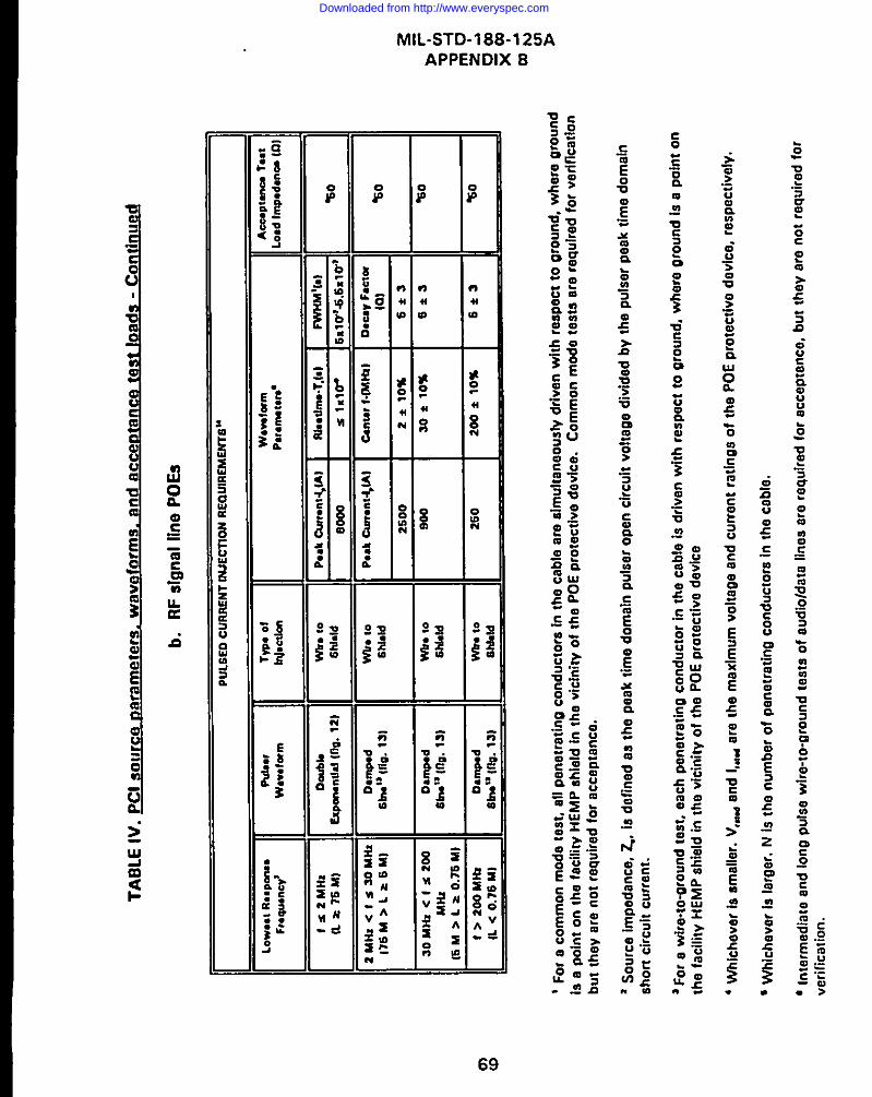
Ot w
TA
BL
EIV
.p
Cls
ou
rce
oar
amef
ers.
wav
efo
rms.
and
acce
rtta
nce
test
Ioad
s-
Co
nti
nu
ed
b.
RF
sig
nal
line
PO
ES
PU
LS
ED
CU
RR
EN
TIN
JEC
710N
RE
OU
IRE
ME
NT
E”
Lo
w.e
IR
.9P
0M.
Acu
Pt.
na
lost
F,.q
u.n
cy’
W*.
.l0rm
,
=&&
,P**
,::+
I
:~~
,~~~
~~~’
‘m’’’
m~o
:o:
2kaN
I<ls
soM
mO
.lnp
dW
I.@
P*A
cam
.nt4
JA
lti
me
?l.fh
tlk
d
176
M>
La6
M)
D*U
VF
.erm
Sb
n”
(fig
.13
1sh
ldd
Iol
%0
2s00
2*10
%6*
3
30M
Nzc
Is20
0O
.mp
.dm
.10
Oo
aso
*10
%6*
SS
bn
”lf
lg.
1s)
%.0
Mtk
zS
hla
ld
(6M
>L
=0.7
6MI
t>2o
oka
Nz
Om
ipo
dw
.to
260
200
*10
%tL
<0.7
6M
I6*
361
rN”
{flo
.1S
.1%
0S
hb
ld
vF
or
aco
mm
on
mo
de
test
.al
lp
enet
rati
ng
cond
ucto
rsIn
the
cabl
ear
esl
mul
tana
ousf
vdr
iven
with
rasp
ecc
togr
ound
,w
here
grou
ndis
apo
int
onth
efa
cilir
vH
EMP
shie
ldin
the
vici
nity
ofth
ePO
Epr
otec
tlva
davl
ce.
Com
mon
mod
ste
sts
ara
raqu
lrad
for
verff
lcat
lon
but
ihay
are
not
raqu
ired
for
acce
ptan
ce.
‘S
ou
rce
imp
edan
ce,
2..
lad
efin
edas
the
pea
kti
me
do
mai
np
uls
ero
pan
circ
uit
volt
age
div
ided
by
the
pu
laer
paa
kti
me
do
mai
nsh
ort
circ
uit
curr
ent.
aF
or
aw
ire-
to-o
rou
nd
teat
,ea
chp
enet
rati
ng
con
du
cto
rin
the
cab
leia
dri
ven
wit
hre
spec
tto
oro
un
d,
wh
ere
aro
un
dia
aP
Oln
to
nth
efa
cilit
yH
EM
Pah
lald
inth
evi
cin
ity
of
the
PO
Ep
rote
ctiv
ed
evic
e
4W
hic
hev
erla
smal
ler.
V,*
and
I,tid
are
the
max
imum
volta
gean
dcu
rren
tra
tings
ofth
ePO
Epr
otec
tive
devf
ce,
resp
ectiv
ely.
GW
hic
hev
arla
Iarg
ar.
NIs
the
num
ber
ofpe
netra
tirt~
cond
ucto
rsin
the
cabl
e.
‘In
term
edia
tean
dIo
no
pu
lse
wir
e-to
-gro
un
dte
sts
of
aud
iold
ata
lines
are
req
uir
edfo
rac
cep
tan
ce,
bu
tth
eyar
en
ot
req
uir
edfo
rve
rifi
cati
on
.
Downloaded from http://www.everyspec.com

MlL-STD-l 88-1 25A
APPENDIX B
TABLE IV. PCI source parameters. waveforms. and accemance test loads-Continued
c. Notes to TABLE IV
7 f = 150/L MHz, where L ia tha largest dimansion of tha associated antenna in metars. When f s2 MHz, a double exponential pulse is required. When f > 2 MHz, a dampad sinusoidal waveform is
specified.
o Signal conductor terminated to the shield with 50 Q. The shield conductor is electrically bondadto tha facility HEMP shield.
0 An antenna shield ia considered buried when it terminates at a buried antenna and Iesa than 1 m
(3.3 ft) of ita total length is not coverad by an aamh or concreta fill. A conduit is considered buriedwhen it connects two protected volumes and less than 1 m (3.3 ft) of its total length is not coveredby earth or concrete fill.
1~For a Shield. to-ground test, maximum faasibla length of the antanna Iina shield is driven with
raspect to ground, where ground ia a point on the faciliw HEMP shield in the vicinity of the POEprotective davice.
I I For a conduit-to.gr~u”d tast, maximum feasible length of tha conduia iS driven with rasPect to
ground, where ground is a point cm the facility HEMP shield in the vicinity of the conduitpenetration.
!z ~,ri”g internal to the condUit is terminated at the installed eqUiprnent, if Present, Other internal
wiring is bundled together and terminated in common 2 Q resistors at aach end. Tha conduit iswelded to the facility HEMP shields at both ends.
“ The damped sinusoidal waveform is a design objective. Tha minimum requirement is 10 inject thacurrent output from a PCI sourca with 2 50 Q source impedanca and short circuit currant l(t) whichsatisfies the following:
whera t is time in saconds, T is tha prescribed peak currant in amperes, f. is tha urascribad canterfrequency, Ko, is a scaling constant which can be determined basad on initial conditions (see fig.13)and T is the time of the first zero crossing or 1If. which aver occurs earlier.
,. For antennas mounted ~“ towers roller than 25 m (82 ft), there is an additional wised currant
injection requirement. This requirement is a 2 ( ? 10%) MHz dampad sinusoid of 500 A peakamDlitude, and Q = 5 ? 3.
70
Downloaded from http://www.everyspec.com

ic 0.9i—-
D
+ 0.5 izIllUu3v 0.1:
. .
0
i-
.0
-i
MIL-sTD-188-125AAPPENDIX B
I. . I (t) = KDEi(G-~t- .-O1)
I = PEAK CURRENT (TADLE IV)
= FUNCTIONS OF rR AND FWtiM
,I
-- ‘R --;
NO SIGNIFICANT
UNDERSHOOT ATLATETIME
. .TIME
FIGURE 12. DoUb Ie exoonentl al waveform. .
<D5i,-~,in(2sfct)II \,~–
4
i = PEAK CURRENT (TA13LEIV)
= CENTER FREOUENCY (TABLE IV)
u~’ ‘=f: ‘:= T,ME,;,Q = OECAYCONSTANT (TABLE IV)
// Kos = SCALINGCON=ANT
TIME
FIGURE 13. Damned sinusoidal waveform
71
,.
Downloaded from http://www.everyspec.com

—=
1:’.=-. ...ll
:-
MIL-STD 188-125A
APPENDIX 6
72
Downloaded from http://www.everyspec.com

TABLE V. i Ijvlax ml m allowable residual internal re~o nse characte ristics for e r&t ical OEs-ContinuedP
Class of Electrical POE Type of Injection Type of Peak Peak R(otw~f RiseMeasuromont
Root ActionCurrt (AJ S)
RF Antenna LinesReceive C)nt
Jsignal Con uctor Drive Wire-to-shield Wire Current 0.1 No damage or performance deoradatlonf
Shield current 0.1 1X1O’ 1.6X1O’
Receive OnlyShield Drive Shield-to-ground Wire Current 0.1 No damage or performance degradation’
Shield current 0.1 1X1O’ 1.6x10³
Transmit and TrnnsceiveShield Conductor Orive Wire-to-shield Wire Current 1.0 No damage or performance degradation’
Shield current 0.1 1X1OJ 1.6x1 O-
Transmit and TransceiverShield Drive Shield-to-ground Wire Current 0.1 No damage or performance degradation’
Shield current 0.1 1X101 1.6 X10⁴
Conduit ShleldaSlon@ and Low Current PowePBurled or Nonburied Conduit-to-ground Bulk current 0.1 1 x 10J 1.6 X1O*
Intermediate Current Powe?Buried or Nonburied Conduit-to-around Bulk current 1.0 1 x 10’ 1.6 X1O’
“i?;,i’#?d;~#d Conduit-to-Oround Bulk current 10 1 x 10’ 1.61 X1O’
“ Low CUw.nt Pow., 11”.. .t. tha.. with a marknurn op.rmlw .“rt.nt s 1 A. I“t. rmedlate cwre.t pow., II... w. them with mmlrrwm .p.mtlno CIIrtwtt b.twm. 1 A ed 10 h. Mioh Ouffent
POW., Iin.n Of. It,... whh morlnwm OP.IMIW cwt..! 210 A.
Downloaded from http://www.everyspec.com

MIL-STD 188-1 25A
APPENDIX B
9. Data management (including data quality control procedures, dataacceptability criteria, data processing requirements, annotation and preservation ofdata records, and pass/fail criteria).
h. Safety.
i. Security (see B 40.10).
j. Test schedule (including priority of measurements).
Data item description DI-NUOR-80928, “Nuclear Survivability Tests Plan, ” shall beI used.
40.8 Test re~ort requirements.
40.8.1 Accemance test reDofi. A PCI acceptance test report shall be Drepared.As a minimum, the test report shall contain the following information:
a. Facility identification and test plan reference.
b. A discussion of any deviations from the test plan and requirements ofthis appendix.
c. Copies of the measured results, along with sensor calibrations andinstrumentation settings required to convert the data to engineering units.
d. A summary table of the norms of the measured internal responses andcomparison to the maximum allowable residual internal response characteristics
I
(see table V).
e. Pass/fail conclusions.
Data item description DI-NUOR-80929A, “Nuclear Survivability Test Repom, ” shallbe used.
40.8.2 Verification test reoort. A PC! verification test report shall be prepared. Asa minimum, the test report shall contain the following information:
a. Facility identification and test plan reference.
74
Downloaded from http://www.everyspec.com

MIL-STD 188-1 25A
APPENDIX B
b. A discussion of any deviations from the test plan and requirements ofthis appendix.
c. Copies of the measured results, along with sensor calibrations andinstrumentation settings required to convert the data to engineering units.
d. A summary table of the norms of the measured internal responses andcomparison to the maximum allowable residual internal response characteristics(see”table V).
e. Test conclusions (including a definitive statement of HEMP hardnessof mission functions, based on the continuous wave immersion (see appendix C)and PCI test results and supponing analysis).
f. Test chronology (including a saquence of events and identification offailures, upsets, or interference observed and the conditions under which theyoccurred).
Data item description DI-NUOR-80929A, “Nuclear Survivability Test Report, ” shallbe used.
40.9 Post-test analvsis reou ireme nts.
40.9.1 #malvsis of acceota nce test ~. Post-test analysis of PCI acceptancemeasured data is required for data corrections for probe and instrumentationresponse characteristics and conversion of results into norms in engineering units.
40.9.2 pnalvsis of verification test ~. Post-test analysis of PCI verificationmeasured data is required for data corrections for probe and instrumentationresponse characteristics and conversion of results into norms in engineering units.Additional analysis of measured data shall be performed to assist in developing adefinitive statement of facility HEMP hardness. Detailed requirements for post-testanalysis of PCI verification test results shall be established by the sponsoringagency for the test. They will generally include calculations of threat responsesfrom CW immersion and PCI test data, analysis of verification test adequacy,development of hardness conclusions, and recommendations for corrective actions,if required.
40.10 Pata c assI ificat i~. Test data may be classified. DNA-EMP-1 and theclassification guide for the specific facility or system should be consulted forguidance.
75
Downloaded from http://www.everyspec.com

MIL-STD 188-125A
APPENDIX B
40.11 Alternative test methods. When approved by the sponsoring agency, cable
shield injection may be used for verification testing on shielded intrasite control orsignal lines in lieu of the common mode PC! requirement. Maximum required
current amplitude and the prescribed waveform for cable shield injection shall be asshown in table V1. Intrasite cable shields shall be driven over their entire length byremoving or buffering/isolating intermediate grounds and other low-impedancepaths to ground along the cable run. Internal response measurements shall bemade on the bulk cable. Pass/fail criteria of table V apply.
TABLE V1. Cable shield PCI amplitudes and waveforms
Doubla Exponential Waveform (Fig. 12)Class of
Electrical POE Risetime =Peak Current = ?
FWHM
~n(s)
[A]
(s)
Control/Signal Lines (Intrasite) 8000 IS 1 Xloo 25 X107 -5.5 X1O7
t ZR s 1X10⁻⁷ s is a design objective. The minimum requirement is 7X s 5X10⁻⁷S .
2FWHM = 5 x 10+ s to 5.5 x 10⁷ s is a design objective. The minimum requirement is FWHM >2.5 X 10’ S.
50. DETAILED REQUIREMENTS.
50.1 Test conficsuration. Typical PCI test configurations are illustrated in figure14, and a typical data recording system is illustrated in figure 15. The pulsegenerator output may be directly coupled to the circuit under test, or it may becapacitively or inductively coupled. All injection current amplitude and waveformrequirements refer to the signal observed on the axternal current sensor. Theexternal current sensor shall be within 15 cm (6 in) of the external terminal of thePOE protective device, and there shall be no branches in the wiring between thesensor location and the external terminal. The internal current sensor shall bewithin 15 cm (6 in) of the internal terminal of the POE proactive device, and thereshall be no branches in the wiring between the sensor location and the internalterminal.
76
Downloaded from http://www.everyspec.com

MIL-STD 188-125A
APPENDIX B
50.1.1 Accemance test co nfiaurati~. For PCI performed as acceptance testing,the external load shall be an open-circuit termination and the internal load shall be adummy resistor (see B 50.2.3).
50.1.2 ~ r“. For PCI verification testing, the externalload shall be the installed site equipment or an equivalent dummy loadimpedance,la which permits the circuit under test to be energized and performingactual or simulated functions. The internal load for PCI verification testing shall bethe installed site equipment, which shall be energized’ and performing actual orsimulated functions. Isolators shall be installed on the wires under test to directinjected current towards the internal load under test (see figure 14). The isolatorsshall be compatible with site equipment in actual or simulated operating condition.
50.2 Current in-tin requirements.
50.2.1 Ma ximum iniect ion levelq. Maximum required short circuit currentamplitudes, source impedances, and prescribed waveforms for acceptance andverification PCI testing for all classes of electrical POES shall be as shown in tableIV and figures 12 and 13. Common mode PCi injections are required only duringverification testing, and that intermediate and long pulse wire-to-ground tests onintersite audio or data lines are required only for acceptance testing.
50.2.2 Test ina ~. To minimize the possibility of POE protective device arequipment damage, a series of pulses at increasing amplitudes shall be applied asfollows:
a. Pulse at the lowest available current output from the pulse generator.This level shall be less than 10 percent of the maximum amplitude in table IV, orless than
‘When the external equirsmenf is not designed to withstand the test transients, temporawprotection should be provided or a dummy load should be used in place of the external equipment.
‘W/hen the circuit under test operates at voltages greater than 600 V a.c. or 600 V d.c. andcannot safely be tested with power on, PCI verification testing may be performed in a deenergizedcondition. Switches, relay contacts, and other circuit interruptersshallbe placedin the operatingstate to simulatethe power on condition.
77
Downloaded from http://www.everyspec.com
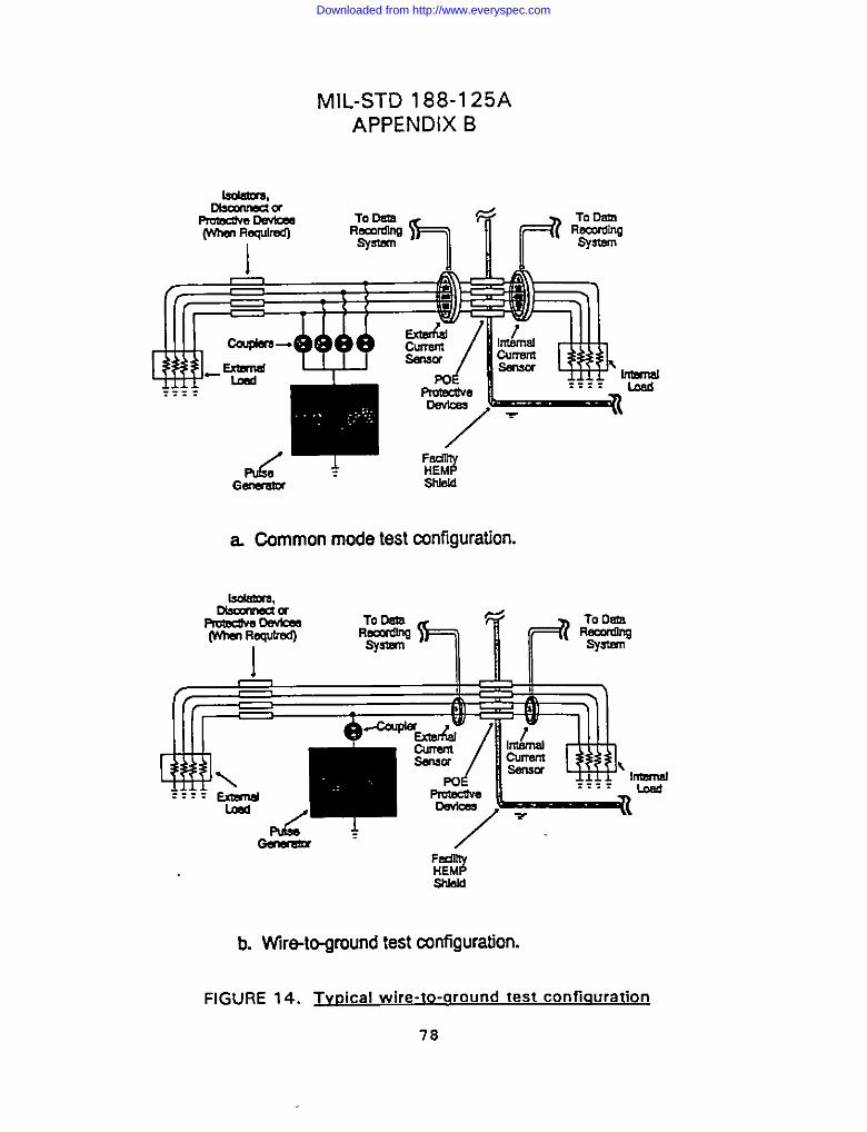
lscudus,
PrR!%%x%xea@hsm Requlrea)
I
MIL-STD 188-125A
APPENDIX B
HEM#SI!Jeld
a Common mode test atnfiguration.
Lwlsmrs,
ITmm4
b. Wire-to-ground test mnfiguration.
FIGURE 14. Tw?ical wire-to-around test configuration
7s
Downloaded from http://www.everyspec.com

MIL-STD 188-1 25AAPPENDIX B
that amplitude which activatas any nonlinear components in the POE protectivedevice, whichever is greater.
b. Perform a series of pulses, Increasing the amplitude by a factor ofapproximately two at each step. When testing several circuits with identical POEprotective devices, this series of intermediate pulses may be abbreviated after thefirst two samples.
c. Pulse at the maximum required amplitude for the circuit undar test. Peakcurrent should not exceed 110 percent of the levels listed in table IV.
CAUTION: Surge arresters in electrical POE protective devices have Iimitad pulselives (2OOO pulses). The number of test pulses delivared to each device should berecorded for inclusion in maintenance records. If the total number of previouspulses on the device exceeds 90 percent of the rated life, surge arresters should bereplaced before starting the test. This sequence shall be used for both acceptanceand verification testing.
50.2.3 ~. Ohmic values of the PCI acceptance testinternal load rasistors for all classes of electrical POES shall be as listed in table IV.For wire-to-ground tests, only the penetrating conductor under test requires thespecified termination. For conduit shield tests, internal wiring shall be terminatedon normal equipment, if presant, and other conductors shall be bundled togetherand terminated with a common 2 fl resistor at each end. Wiring which connectsthe load resistor between the internal terminal of the POE protective device and itsenclosure shall be less than 30 cm (12 in) in length.
50.3 Mmwmmud fu nctional observ-.
50.3.1 Data eour ireme~. At each step in the testing sequence, for bothacceptance and verification testing, the external Pulse amplitude and waveform andthe internal pulse amplitude and waveform shall be recorded.14 The internal pulsewaveform shall be recorded for 5 ms aftar the start of the PCI short drive pulse,with recording instrument sweep speeds which allow resolution of the early,intermediate, and late time response.
!. Mentie poE protectivedaviceleadsinto a special Protective volume inside the
electromagnetic barrier. amplitudes and waveforms ehall also be recorded on all eleti”cal POESthrough the special protective barrier into the protected volume. The measurements shall be made
in the orotected volume. Pass/fail criteria for these date are the same aa the paeslf ail criteria forother internal response measurements.
79
Downloaded from http://www.everyspec.com

lvllL-STD 188-125A
APPENDIX B
[NSl?UJMEhTATION SHIELDI
DATA
n
DATA
RECORDER S=L~ RECORDER S-L?
A 1~%~ $vasclLlmamPE OR OSCILLOSCOPE OR
TRNLSIEhT DIG=R HSIENT DIGITIZER
~0 INPUT EY7. ~lG. EOOINPUT m. TRIG.o
EARLY TIME LATETIME
ATTENUATOR ATTENUATOR
\
~ FEED THRU
,- ———--— — ————--——— Jm~smsmu
FIGURE 15. Tvoical PCI data recordina svstem
so
Downloaded from http://www.everyspec.com
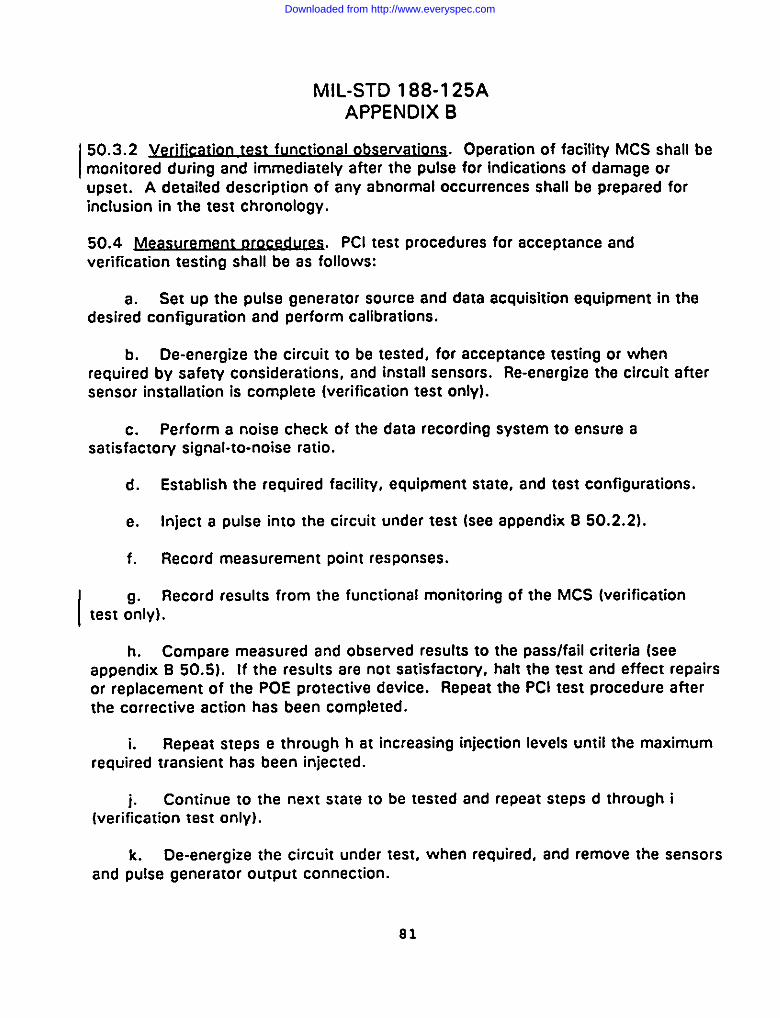
MIL-STD 188-1 25A
APPENDIX B
50.3.2 Verification test functional obsarvatio~. Operation of facility MCS shall bemonitored during and immediately after the pulse for indications of damage orupset. A detailed description of any abnormal occurrences shall be prapared forinclusion in the test chronology.
50.4 Wrement ~ r. PCI test procedures for acceptance andverification testing shall be as follows:
a. Sat up the pulse ganarator source and data acquisition equipment in thedesirad configuration and parform calibrations.
b. De-energize tha circuit to be tested, for acceptance testing or whenrequired by safety considerations, and install sensors. Re-enargize the circuit aftersensor installation is complete (verification tast only).
c. Perform a noise check of the data recording system to ensura asatisfactory signal-to-noise ratio.
d. Establish the raquired facility, equipment state, and test configurations.
e. Inject a pulsa into the circuit under test (see appendix B 50.2.2).
f. Record measurement point responses.
9. Record results from the functional monitoring of the MCS [verificationtest only).
h. Compare measured and observed results to the pass/fail criteria (seeappendix B 50.5). If the results are not satisfactow, halt the test and effect repairsor replacement of the POE protective device. Repeat the PCI test procedure afterthe corrective action has been completed.
i. Repeat steps e through h at increasing injaction levels until the maximumrequired transient has been injected.
i. Continua to the next state to be tested and rapeat steps d through i(verification test only).
k. De-energiza the circuit under tast, when required, and remove the sensorsand pulse generator output connection.
81
Downloaded from http://www.everyspec.com

MIL-STD 188-1 25AAPPENDIX B
1. Disconnect the electrical surge arrester from the circuit. Measure thevoltage at 1 mA d.c. of a metal oxide varistor or the d.c. breakdown voltage of aspark gap. Compare the measured resuks to the device specifications. If theresults are not satisfactory, effect repairs or replacement of the POE protectivedevice. Repeat the PCI test procedure after the corrective action has beencompleted.
m. Reconnect the electrical surge arrester, and restore the circuit to itsoperational configuration.
n. Continue to the next circuit to be tested and repeat steps b through m.
50.5 Pass/fail criteria.
50.5.1 Internal resmonse Dass/fail criteria. The POE protective device shall beconsidered satisfactory when both of the following criteria are met:
a. Norms of the measured internal response waveforms, at all short pulseinjection levels, do not exceed the maximum allowable norm values of table V forthe applicable class of electrical POE.15
If internal responses measured in the PCI verification test cannot bediscriminated from circuit operating and noise signals, the test shall berepeated in a power-off (acceptance) configuration. The pass/faildetermination for internal response norms shall then be made using theresulting power-off data.
b. Post-test physical inspection of the POE protective device, surge arrestermeasurement of voltage at 1 mA d.c. current (for a metal oxide varistor) or d.c.breakdown voltage (for a spark gap), and resPonse data analYsis indicate that thedevice has not been damaged or degraded by the test pulses.
The internal response pass/fail criteria apply for both acceptance and verificationtesting.
Iowen me ~rote~ed side of the pOE protective device is contained within a special protective
volume, norms of the measured internal responses must not exceed design values for that specialprotective volume.
I 82
Downloaded from http://www.everyspec.com

MIL-STD 188-1 25A
APPENDIX B
50.5.2 Verification test fu nctional oass/ fail criteria. Hardening of equipmentwithin the electromagnetic barrier shall be considered satisfactory when both of thefollowing critaria are mat:
I a. No damage to MCS occurred during the PCI verification testing.
b. No mission-impacting interruption of mission-essantial functions or upsetsof MCS occurred during the PCI verification tasting.’e
50.5.3I@&2u@s. Any failura to satisfy the Internal response or functionalsuccess critaria shall be considered a HEMP vulnerability. An investigation into thecause of the possibla vulnerability shall be conductad. Tha condition shall bacorrected, if possible, and the PCI verification tast sequenca shall be repeated.
‘me determination of whether an observed interruption or upset impacts the mission is rheresponsibility of she operational auchofiry for the faciliry.
83
Downloaded from http://www.everyspec.com

MlL-STD-l 88-1 25A
APPENDIX C
CW IMMERSION TEST PROCEDURES17
10. GENERAL
10.1 -. This appendix is a mandatory part of the standard. The information
contained herein is intended for compliance. This appendix establishes procedures
for CW immersion testing of the electromagnetic barrier required for low-risk HEMP
protection of critical ground-based facilities with time-urgent missions. Theprocedures are applicable for testing other HEMP-hardened facilities, whenspecified by the procurement documentation.
10.2 Armlications. These procedures shall be used for verification testing of the
facility HEMP shield and aperture POE protective treatments, as required by
DETAILED REQUIREMENTS of Ml L-STD-l 88-1 25A.
20. REFERENCED DOCUMENTS
20.1 Government documents. The following documents form a part of thisappendix to the extent specified:
DI-NUOR-80928 - Nuclear Survivability Test Plan
DI-NUOR-80929A - Nuclear Survivability Test Report
DOD-STD-2169 - High-Altitude Electromagnetic pulse (HEMpl Environment(U) (document is classified Secret).
DNA-EMP-1 - Electromagnetic Pulse (EMP) Security Classification Guide(U) (document is classified S-RD).
(Copies of specifications, standards, handbooks, drawings, and publicationsrequired by contractors in connection with specific acquisition functions should beobtained from the contracting activily or as directed by the contracting officer. )
30. DEFINITIONS
30.1 Illuminating field. At a location with respect to the transmitting antenna is
‘ 7HEMP.UN.W0 zest voe~ures are 18mPorarilvincluded a. aPP.ndk.S 1. MIL.STO. 188-12S: it !. inc.nded that Ihes.
procedure. will ultimatdv be promulgated as separat. standards outsid. Ofthe MlL-STD-l 88-.erie*.
84
Downloaded from http://www.everyspec.com

MlL-STD-l 88-1 25A
APPENDIX C
the total electromagnetic field, including ground effects, which would be measuredat that point if the facility or system under test was not presant. Thus, theilluminating field does not include reflections from the facility under test.
30.2 J%incioal comoone t of then illuminating field. A magnetic or electric fieldcomponent which is maximized by the antenna geomet~ and ground effects. Forexampla, azimuthal magnetic field and vertical electric field are principalcomponents of the illuminating fiald of a vertical monopole antenna over a ground~lane.
30.3 J?eference field. The reference field In a CW immersion tast is a measuradfield for monitoring the output from the transmitting antenna. This field is recordedin the reference channel of the network analyzer used for data acquisition. Thereferance sensor must be placed at a location with respect to the transmit antannaand subsystem shelter under test are negligible at all frequencies of interest. Tominimiza errors in the subsequent data analysis, the refarence sensor shouldmeasure a field component which is relatively smooth and flat over the entirefrequency range being measured. Examplas of such components are:
a. Horizontal polarization. Radially outward horizontal component ofthe magnetic field parallel and near to groundta
b. Vertical polarization. Azimuthal magnetic field parallel and near toground or vertical electric field near ground.
The reference field must ba recorded for two types of measurements:
a. field at the t~ - Measurement of the illuminating field atthe location of the tast object relative to the reference sensor whenthe test object is not present. This is needed for subsequent dataanalysis (extrapolation to threat and establishment of pass/fail criteria -see C 50.6).
b. S@2svstem re~ n - Measurement of the residual responsecurrent inside the subsystem relative to the reference sensor when thefacility is illuminated by the CW field.
‘%ha!wizon:d comwment of the alacwic field or thn venlcd comoon.nt of II!. ma.anado finld SW not be used
because of the low magti!wia al them field componanu CIOX8 to above rrrmmd. At ● Whl shave w!?ad whsra the
msaritude of ties. camoanems becomes Iatge. this maanitude ccmltins nun NIIS in h rsntw of S MHZ to 1 GHz.
85
Downloaded from http://www.everyspec.com

MIL-STD-188-125A
APPENDIX C
50.6 describes the analysis of the data from the above two measurements toestablish pass/fail criteria.
40. GENERAL REQUIREMENTS
40.1 General. The CW immersion test procedure is an element of verificationtesting, performed as soon as practical after the HEMP-protected facility iscompleted and operational. The test method illuminates the exterior surface of theelectromagnetic barrier with radiated CW fields and surveys the interior protectedvolume to identifi shield defects and inadequately protected aperture POES and to
provide data for hardness assessment. Because coupling to exposed externalportions of penetrating conductors may not be efficient, CW immersion has limitedeffectiveness for evaluating conductive POE protection. Therefore, protectionprovided for penetrating conductors is also evaluated with PCI testing (seeappendix B). Both horizontal and vertical Polarization must be used for the incidentfield.
40.2 J%trose. The purposes of CW immersion testing are as follows:
a, To measure attenuation of electromagnetic fields in the HEMP portion of
the spectrum by linear elements of the as-built electromagnetic barrier.
b. To identi~ HEMP shield and aperture POE protective device defects,faulty installation practices, and inadvertent POES, so that repairs can be made.
c. To characterize residual internal field and conducted electromagneticstresses, within limitations of the linearity and planarity assumptions, through post-test analysis.
d. To observe operation of the facility for interference or upset (interferencewhich occurs as the result of the low-level CW excitation may indicate a circuitwhich is particularly vulnerable to HEMP effects)
e. To provide data for HEMP hardness assessment of the facility andbaseline data for the HM/HS program.
40.3 HEMP protection subsvstem test confkm!ration. Ouring conduct of the CWimmersion test, the facility shall be in a normal operating configuration and shouldbe performing actual or simulated mission functions. The HEMP protectionsubsystem shall be intact.
86
Downloaded from http://www.everyspec.com

I
I
MlL-STD-l 88-1 25A
APPENDIX C
40.4 sis reau ireme ntS. Pretest analysis shall be perfarmed ta selecttransmitting antenna Iacatians, reference sensar Iacatians, and measurementpaints. Transmitting antenna Iacatians shall be chasen to obtain the requiredilluminating field strength and efficient coupling to all areas on the electromagneticbarrier surface. Reference sensar locations shall be chosen to monitor thetransmitting antenna output and determina the illuminating field. Measurementpoints shall be chosan to provide representative mappings af fiald responses withinthe protected volume and special protective volumes and current responses withinthe internal cable plant.
40.5 ~iome nt reau ireme n~. Test equipment required far CW immersiontesting is identified in table VI].
TABLE V1l. CW im~ test eaul~i
Equipment characteristics
Network Anafyzer[sl’ 5 MHz*1 GHz, minimum e.ensitl.lw 8s required for maasurencent smskivity
Power Ampflfierlsl’ 5 MHz-1 GHz. amplification .ss required for measurement sensitivity
Antennalsla 5 MHz-1 GHz
Sensors Free-field, current, 1 MHz. 1 GHz
Praamplifiefs’ 5 MHz-1 GHz, amplification and noise figure as raqulred for m=suramamsensitivity
Data Recorder’ Dual channel
Fiber Optic l-inks’ 5 MHz-1 GHz, up to 100 maters In length
Miscellaneous Cables As requiredand Attenuators
1Use of a kcoraonal commnar with an lEEE4aa ganaraf purpose Intaciace bus IGF’M to control thenetwofk anofyzer, the fker 00:Ic Ilnks. pmampfiflera. and data Oc@dllOn &Icfuti9 Stomee of test dataon magnallc disk or taoel Is strongly racommanded.~ypicaffy. saveraf Uscoar power amplifiers am required. For axample, 150 watts for 1 MHs -220 MHz,
:nd 10 waits for 200MHz. IGHZ.fn order 10 cover a broad fmruoncy rmvaa. several tnms!mfs mtcsmas may be raquirad. Eaamplaa ara:
Horfzonml dlpolea and vrrnlcaf monorso!es for fmmmdas uo to 50 MHz sssd vaffws 100 Padodlcmctannas for both polarfza:lons for f roquoncv rmges suds aa 30Mf4z-100MHz and 90 MHz to 1 GHz.hypicalfy. low-watt linear ampfifkm having a gain of more than 30d&‘Mu.w have at Iaam 30da dynandc range. Must bo abla 10 eatmd the maasurammt rsnge by use ofaltenua:ors md preamplifiers.
87
Downloaded from http://www.everyspec.com
MIL-STD-188-125A
APPENDIX C
40.6 Operational imDact analvsis and risk. Since the electromagnetic barrier mustremain intact during conduct of the CW immersion test and use of electrically noisyequipment which is not part of the normal site equipment complement must berestricted, unusual operations (facility modification, maintenance) may be affected.Mission operations can continue normally, except that a special sequence ofactivities may be required so that the facility can be tested in its various operatingstates (transmitting, receive-only, etc.). Radiated signal levels are low and presentno hazard to equipment, but frequency clearance and bands in which transmissionsmust be suppressed may be required to avoid self-interference or interference withnearby facilities. Normal electrical safety precautions apply.
40.7 Test r)lan and Drocedures. A comprehensive, site-specific test plan anddetailed test procedures for CW immersion testing shall be prepared. These maybe combined into a single document or two separate documents may be used. Asa minimum, the test documentation shall contain the following information:
a. A statement of the test objectives.
b. Facility identification and description (including a site plan, floor plan ofthe protected volume, list of shield POES, list of mission-essential equipment insideand outside the electromagnetic barrier, and a description of the HEMP protectivesubsystem).
c. Transmitting antenna locations, reference sensor locations, and expectedmeasurement sensitivity of the illumination and instrumentation system.
d. CW illumination and data acquisition equipment identification (includingmanufacturer, model and serial numbers, characteristics, and detailed calibrationprocedures).
e. Detailed test procedures (including facility configuration requirements,equipment operating states, diagrams of the test configuration, step-by-stepprocedures, and measurement point locations).
f. Data management (including data quality control procedures, dataacceptability criteria, data processing requirements, annotation and preservation ofdata records, and pass/fail criteria).
9. Safety.
h. Security (see C 40.10).
88
Downloaded from http://www.everyspec.com
MlL-STD-l 88-1 25AAPPENDIX C
i. Test schedule (including priority of measurements).
Data item description DI-NUOR-80928, “Nuclaar Survivability Test Plan-, shall beused
40.8 Test reoo~ n. A CW immarsion test repoti shall be prepared. Asa minimum, the test report shall contain the following information:
a. Facility identification and test plan reference.
b. A discussion of any deviations from the test plan and requirements of thisappendix.
c. Copies of the measured results, along with sensor calibrations andinstrumentation settings required to convert the data to engineering units. Ideally,the data are acquired with an automated (and calibrated) data acquisition systemwhich automatically folds in any calibration factors, gain or attenuation settings. Inthis case, processed data can be shown in place of the directly measured results.
d. Test conclusions based on CW immersion and PCI test results andsupporting analysis. A definitive statement of HEMP hardness of mission functionswill be made based on the conclusions of the complete batte~ of verification tests(including PCI and CW immersion].
e. Test chronology - including a sequence of events and identification offailures observed and the conditions under which they occurred.
Data item description DI-NUOR-80929A, ‘Nuclear Survivability Test Repon”, shallbe used.
40.9 post-t~ss re~.i A post-tast analysis of the measured datashall be performed to assist in developing a definitive statement of facility HEMPhardness. Detailed requirements for post-test analyses of verification test resultsshall be established by the sponsoring agency for the test. They will generallyinclude calculations of threat responses from CW Immersion and PCI test data,analysis of verification test adequacy, development of hardness conclusions, andrecommendations for corrective action, if required.
40.10 ~. Test data may be classified. DNA-EMP-1 and theclassification guide for the specific facility or system should be consulted forguidance.
89
Downloaded from http://www.everyspec.com

MIL-STD-188-125A
APPENDIX C
40.11 Alternative te st methods. When CW illumination of a facility is not practicalbecause of physical interference with other facilities in the vicinity, the CWimmersion test may be performed using CW current injection on the outer surfaceof the electromagnetic barrier. A site-specific CW shield current injection test planand detailed procedures shall define the shield excitation technique, sourcestrength, injection point, and predicted shield current density distributions.Minimum data acquisition system sensitivity required for verifying the HEMPprotection subsystem effectiveness and pass/fail criteria shall be determined.
When approved by the sponsoring agency, a thorough program of shieldingeffectiveness measurements (appendix A) and a thorough SELDS survey IAW MIL-HDBK-423 guidance may be used for verification testing in lieu of the CWimmersion test.
50. DETAILED REQUIREMENTS
50.1 Test co nfiouration. The CW immersion test configuration is illustrated onfigure 16. Swept or stepped CW excitation, generated by the network analyzersource, is propagated to the transmitting antenna location via a hardwired or fiberoptic link.
The signal is amplified and radiated from the antenna (a vertical monopole,horizontal dipole, log periodic, rhombic or other antenna) to illuminate the facility.The reference sensor, located in a clear area where the measured field has a knownrelationship to the total field illuminating the facility, monitors the source output.Free-field, surface current or charge density, current and voltage sensors monitorthe response at measurement points inside (and outside, if desired) theelectromagnetic barrier. Preamplifiers and fiber optic links are used, as required, inthe measurement channels. Reference and measurement point data are monitoredon the network analyzer and recorded. Figure 17 illustrates a sample 1 MHz to100 MHz data record, where identical B sensors (time rate of change of themagnetic induction field) are employed in both channels and the reference channelis a direct measurement of the illuminating field.
50.2 Transmitting antenna Iocat ions. Transmitting antenna locations shall bechosen to illuminate all areas on the barrier surface with the radiated fieldexcitation. Three or four locations around the periphery of the facility will normally
90
I
Downloaded from http://www.everyspec.com

MlL-STD-l 88-1 25A
APPENDIX B
91
Downloaded from http://www.everyspec.com

MlL-STD-l 88-1 25A
APPENDIX C
be required. The antenna shall be placed as far from transmit antenna as possible,
within physical and measurement sensitivity constraints.’g
50.3 Measurement locations. For facilities less than 900 mz (10,000 ftz) inshielded floor area, a minimum of 5 (x3 components) electric or magnetic free-fieldmeasurement locations, 3 (x2 components) surface current or charge densitymeasurement locations, and 20 current measurement locations throughout theshielded volume shall be chosen for each transmitting antenna location. For largerfacilities, the number of measurement locations shall be increased in proportion tothe total shielded floor area.
Measurement points for each transmitting antenna location should beconcentrated in the 40 to 50 percent of the protected volume and in specialprotective volumes physically closest to electromagnetic barrier surfaces which aredirectly illuminated.
Internal free-field measurement points shall be chosen to provide arepresentative mapping of field responses within the electromagnetic barrier. Thefree-field measurements shall be made in areas which are relatively clear ofequipment. The three oflhogonal components of the field response shall berecorded. Internal magnetic free-field measurements should normally beemphasized.
Internal surface current or charge density measurements shall principally be
made at penetration areas on the electromagnetic barrier. Internal surface current
density measurements should normally be emphasized. when measuring surface
current density, the two orthogonal components of the response shall be recorded.
Internal current measurement points shall be chosen to provide arepresentative mapping of current responses in the internal cable plant. Currentmeasurements shall be made on selected penetrating cables near their POEprotective devices, on selected cables with long interior runs or layouts producingefficient coupling geometries, and on input cables to selected mission-essentialequipment.
mRo,ult, ~an ~. intorprei~as pi... wave r.srm...s when: R > A.W =d R > 2 Da/A- - where Rig the
distnnc. from zhe antenna to the barri.r. k ti is th. wav.iength of the Iow. sr radimed frequency, i- i8 the
wavelength of the Idghast radiated fraqmncy, and D is the antenna char. cterisdc length or Iargast barrim dlmansiontrms.erse m the propagation direction of the illuminating fimld. When these inequalities ara not ●auafied, mm-field andvav. curvature effects may be significant
92
Downloaded from http://www.everyspec.com

MlL-STD-l 88-1 25A
APPENDIX C
o
: -!0u
: -’050e -110gzwW
-160
-100
FREQUENCY ( Hz)
a. Nobe/opmUnc stsud KSX
o
-80:u
b -s01?+z -120aoIAzwW -160
-1oo \ .. . “ 1 1 I Ill
FtGuRE 17. mmersion test ~d
93
Downloaded from http://www.everyspec.com

MIL-STD-188-125A
APPENDIX C
An interior electromagnetic survey, with CW excitation applied from eachtransmitting antenna location, shall be performed to locate areas of maximumresponse. Particular attention should be given to barrier penetration areas.Additional free-field and current measurement points shall be chosen where thelargest signals are detected during the survey.
50.4 Test frequencies. Test data are desired at frequencies from 100 kHz to 1GHz. h is usually necessary to divide the frequencies into several bands, selectingdifferent antennas to maximize the radiation efficiency in the different bands.
50.5 Measurement Drocedures. CW immersion test procedures shall be asfollows:
a. Set up the data acquisition equipment in the desired configuration andperform calibrations. Minimum sensitivity of the data acquisition system should be147 dBm or lower.
b. Set up the transmitting antenna and map its fields. The principalcomponent of the illuminating fieldm should be at least 1 V/m from 1 MHz to 50
MHz and at least 0.1 V/m from 50 MHz to 100 MHz at the point on theelectromagnetic barrier closest to the transmitting antenna. As a design objective,the principal component of the illuminating field should be at least 0.1 V/m from100 kHz V/m from 100 kHz to 1 MHz and 0.01 V/m from 100 MHz to 1 GHz.Choose a reference sensor location.
c. Perform a check of each data acquisition channel to verify link noiseimmunity. Disconnect the sensor and terminate the sensor cable in itscharacteristic impedance. Energize the radiating source, and record the receivedsignal strength as a function of frequency.
d. With the radiating source energized, perform a survey of the area to bemonitored and select the additional measurement locations.
e. Place the sensor and use preamplifiers as required to obtain the desiredmeasurement sensitivity.
‘Vhe illuminating field is expressed as: c x B, orcx E_light, B-
where c equals the speed ofequals the magnetic induction field~ equals the electric field.
94
Downloaded from http://www.everyspec.com

MlL-STD-l 88-1 25A
APPENDIX C
f. With the source and data acquisition equipment in a normal configuration,except that the power amplifier is turned off, record the noise and operating signalresponse at the measurement point as a function of frequency. Narrow band filterand long sweep tima settings of the network analyzer are necessa~.
9. Turn the power amplifier on and record the reference and measurementpoint responses as a function of frequancy, using the same filter and sweap timesettings employed for the noise and operating signal measurement.
h. Perform data quality control. Annotata and presewa the data records!
i. Record any interference with the operation of facility equipment observedduring the CW immersion test. Also record test and operational conditions whichexisted at the time the interference was notad.
i. Continue to the next measurement location and repeat steps e through i.
k. When measurements for ona transmitting antenna location are completed,continua to the next transmitting antenna location and repeat steps b through j.
50.6 ~assl fail -.21
50.6.1 ]nternal f~s ureme nt~. In frequency bands where the measurementdynamic range is less than the required attenuation, internal CW immersion frea-field and surface current or charge dansity measurements shall be consideredsatisfactory when there is no observable test point response above the noise andoperating signal level.
In tha frequency band where the measurement dynamic range is greater thanthe required attenuation (expected to be at least 5 MHz to 100 MHz) internal CWimmersion field measurements shall be considered satisfactory when the test pointresponsas are below the principal component of the illuminating fiald by at least theraquired attenuation. This success criterion is expressed by the followingequations:
21Tb,a ~a,,,f~ ~ri,eri, ~w to & m.asw~an:s &a in tie Pmtocmd vc.lunu. ROXP.%W* ma~r~ in ● *e~~
p:o:ectiva volume nuti not .xcaad dmign values for thal spatial Prowtiw vdunu.
95
Downloaded from http://www.everyspec.com

I
MlL-STD-l 88-1 25A
APPENDIX C
50.6.1.1 For internal maanetic induction field measurements.
8000Binternals ~ x Billuminacing U<8X10⁸
< 10-s x B flltmfmtfng O28X1OS
where
Bhmd = measured component of the magnetic induction field at atest point inside the electromagnetic barrier (Wb/m2)
B~W = principal component of the illuminating magnetic induction
field at the point on the electromagnetic barrier closest to the transmitting
antenna (Wb/m2)
‘b = angular velocity (s”l)
50.6.1.2 For internal electric field measurements.
Efiterml s 10’5 x Eill~nating
where
Etimd = measured component of the electric field at a test pointinside the electromagnetic barrier (V/m)
EaMti = principal component of the illuminating electric field at
the point on the electromagnetic barrier closest to the transmitting
antenna (V/m)
50.6.1.3 For internal surface curren t densitv measurements.
J~ 6.4x10⁹
Blllurn,l x Bimcnimting U<8X10E(J
96
Downloaded from http://www.everyspec.com

MlL-STD-l 88-1 25AAPPENDIX C
J_,o+ = measured surface charge density at a test point inside theelectromagnetic barrier (A/m2)
50.6.1.4 For internal charae densitv mea~.
where
Q*. = measured surface charge density at a test point inside theelectromagnetic barrier (C/m2)
50.6.2 ~rnal current measur ements, Internal CW immersion currentmeasurements shall be considered satisfactory when the peak value of the threat-extrapolated response, transformed into the time domain, does not exceed 0.1amperes and the peak derivative does not exceed 107 A/s. This success criteria isexpressed by the following equations:
for all time f, where
f, = the lowest CW immersion tast frequency (Hz)
fu = the highest CW immersion test frequency (Hz]
~.,/Zr) = threat-extrapolated current in the frequency domain (A/Hz)I
97
Downloaded from http://www.everyspec.com
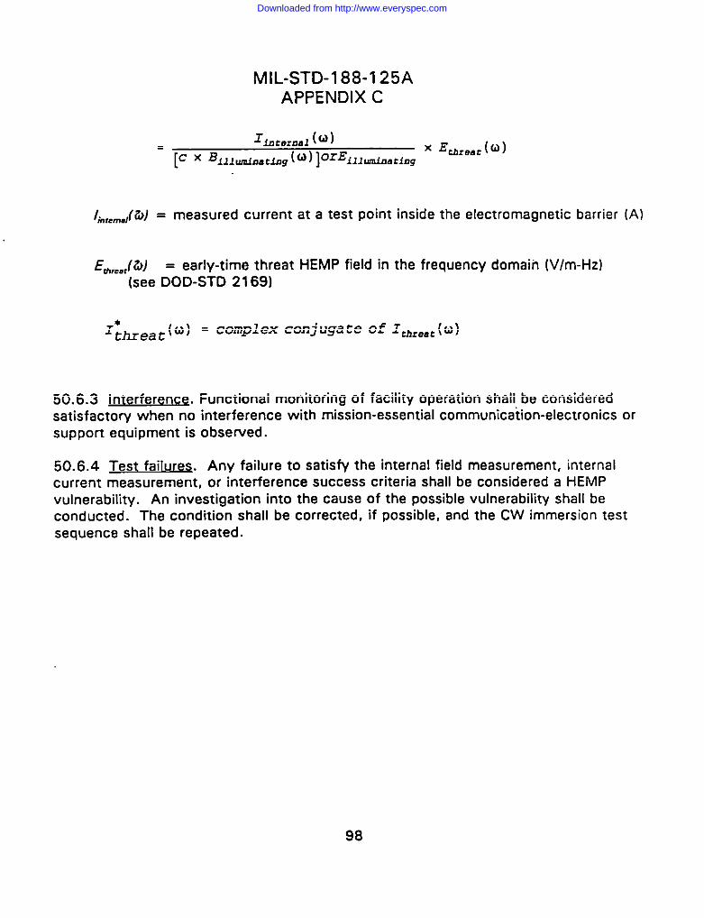
MlL-STD-l 88-1 25A
APPENDIX C
1.,.,,m,,(fi) = measured current at a test Point inside the electromagnetic barrier (A)
E~,,JZ4 = early-time threat HEMP field in the frequency domain [V/m-Hz)
(see DOD-STD 2169)
+h=eac(u) = complex conjugate of rmeat(o)
50.6.3 jnterferenc~. Functional monitoring of facility operation shall be consideredsatisfactory when no interference with mission-essential communication-electronics orsupport equipment is observed.
50.6.4 Test failures. Any failure to satisfy the internal field measurement, internalcurrent measurement, or interference success criteria shall be considered a HEMPvulnerability. An investigation into the cause of the possible vulnerability shall be
conducted. The condition shall be corrected, if possible, and the CW immersion test
sequence shall be repeated.
98
Downloaded from http://www.everyspec.com
Custodians:Army-SCNavy-ECAir Forca-90
MIL-STD-188-125ACONTENTS
Praparing activity:Air Forca-90
(Projact SLHC 1252)
Reviaw Activities:OASD-WSAOASD4RArmy -AC, AM, CE,CR,TENavy -MC, NC, NM, OM,TDAir Force-01,02,13,14,15,17,19,89,91,92,93DLA-DHDNA-DSDISA-OCNSA-NSDOD/ECAC-EMDMA-MP
Civil Agancies Coordinating Activities:COMMERCE-NISTGSA-PQBNCS-TS
“ TRANSPORTATION-OSTFEMA
99
Downloaded from http://www.everyspec.com

STANDARDIZATION DOCUMENT IMPROVEMENT PROPOSAL
~TRUCnONS
1. The preparing activity must complete blocks 1, Z. 3, and 8. [n block 1, both the dosument number and revisionlesser ihould be given.
2. The submitter of this form must comple!e block$ II, 5,6. and 7.
3. The preparing activity mus~ provide a reply w!th!n 30 days from receipt of the form.
NOTE: This form may not be used to request coptes of documents, nor to request waivers, Or clarification of
requirements on current contracts. Comments submitted on this form do not constitute or imply authorization towaive any pom”on of the referenced document(s) or to amend contractual requirements.
I RECOMMEND A CHANGE: “ OOcuMFM’‘UMS[R 1. OOCUMIM1OATt(rrw~oOJ211L-STD-188-125A, Vol I
00 CLIMWT TITLE High-altitude Electromagnetic Pulse (HEMP) Protection for Ground:basedC4 Facilities Performing Critical, Time-urgent Missions, Volune I Fixed Facilities
NATURE OF CHANGE (Idmrify ~,ag,zph number ,nd fncfud6 ~ ,ewrite, N _’bfe. AEsxh ●m,, sheen ,, needed)
REASON FOR RECOMMENOAIION
SU71M17TER
NAME@ a%F2124Mld9ebdIW2 b. ORGANIZATION
AOORESS (hcfude ZIU Code) d rSLEPNoNE (Lmcld Area @de) 1. D&tE suehurrm(1) Cmnmerf.ul fwhmtoo)
(2) AuTOVON23{ .Pparahk]
PREPARING ACTIVITY
%“;ir Force C6 Agency (HQAFCbA/TMtB)o TELEPHONE (Inrlude Area Code)(1) Commercwl (2) AUTOVON
(618) 256-2975 576-2975
&OORESS (Inrfude ZiP Code)
607 Pierce Street, Room 303IFYOU 00 NOT RECEIVE A REPLY WITHIN a5 OAYS. CONTACT:
Attn:Oeienn Qu#lity and Standardizatmn Of flCe
Rex XcKinnon 5203 LeesburgPtke. Swre 11103. Falls Ch.rrh. VA 22041.3466
Scott AFB, IL 62225-5621 TeleDhone(703)7SS.Z3d0 AuTOVON 289-23*
3 Form ld26. Clfl UQ . . . .. .. 4,,.,...,. . . . ,.I....l.,. ,$s m, . ...”.. .“..,-” -.. . . . . . . .
Downloaded from http://www.everyspec.com
Top Related