


Languages
Pages
Legal

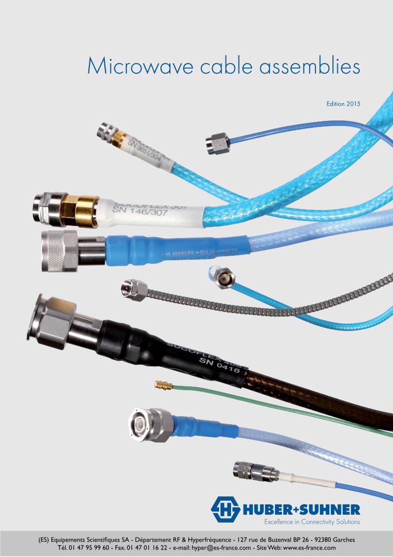
Microwave cable assembliesEdition 2015
(ES) Equipements Scientifiques SA - Département RF & Hyperfréquence - 127 rue de Buzenval BP 26 - 92380 GarchesTél. 01 47 95 99 60 - Fax. 01 47 01 16 22 - e-mail: [email protected] - Site Web: www.es-france.com
Create reliability and high performance
Gen
eral
info
rmat
ion
Form
stab
le
asse
mbl
ies
Hig
h
perf
orm
ance
Engi
neer
ing
info
rmat
ion
Sele
ctio
n
guid
e
Low
pro
file
asse
mbl
ies
Test
asse
mbl
ies
Flex
ible
asse
mbl
ies
Your partner for system solutions
HUBER+SUHNER makes a significant contribution to simpli-fying processes by supplying cables assembled with connec-tor according to customer requirements. The assemblies are manufactured using high-quality cables and connectors, care-fully tested according to the relevant standards and delivered with a certificate upon request.
General assembly information 4
Qualified, high performance 8microwave cable assemblies > SUCOFLEX 100 / 200 / 300 /400
Qualified, low profile, high performance 74microwave cable assemblies > Minibend family
Microwave test cable assemblies 102> Sucotest / TL-8A / TL-P
Flexible microwave cable assemblies 116> Boa-flex / Steel-flex / Multiflex / S-Series
Formstable and handformable 152microwave cables assemblies > Sucoform / Cobra-flex / Semi-rigid
Engineering information 168
Selection guide 178

HUBER+SUHNER Microwave assemblies4 HUBER+SUHNER Microwave assemblies4
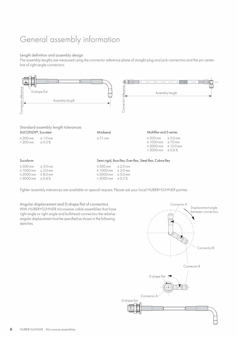
General assembly information
HUBER+SUHNER develops and manufactures coaxial cables and connectors for most applications and in a multitude of versions. The connector series comprise over 1700 different types which prove their qualities daily worldwide. Demanding customers trust the reliability and quality of HUBER+SUHNER products. These products have been tested to IEC, MIL, CECC and other standards. Our extensive know-how in RF technolo-gy enables reliable and competent technical consulting and support. You stand to benefit from a well matched cable and connector range as well as many years vast experience of our engineers.
Microwave cable assemblies to your specificationsMake use of the HUBER+SUHNER custom design service. Increase efficiency and productivity in your company by orde-ring ready-to-use microwave cable assemblies from the specia-lists. Expert assembly by soldering, clamp or crimp technique and inspection records according to your specifications ena-ble you to order with confidence.
Advantages of microwave cable assembliesPurchasing of ready-made microwave cable assembly lines provides important benefits:• Perfect assembly, no rejects• No need for training assembly personnel• No capital investment for assembly provisions• Precisely matched cables and connectors from
the same manufacturer• HUBER+SUHNER guaranties quality
Cables and connectors from the same manufacturer
HUBER+SUHNER Microwave assembliesAbbreviations see page 176 5HUBER+SUHNER Microwave assemblies 5
Gen
eral
info
rmat
ionGeneral assembly information
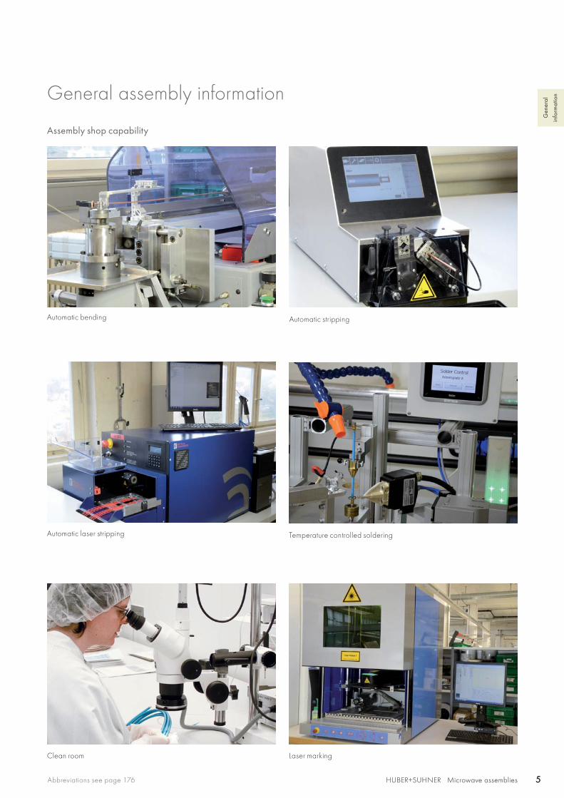
Assembly shop capability
Automatic bending
Automatic laser stripping Temperature controlled soldering
Automatic stripping
Laser markingClean room
HUBER+SUHNER Microwave assemblies6 HUBER+SUHNER Microwave assemblies6
General assembly information
Semi-rigid, Boa-flex, Ever-flex, Steel-flex, Cobra-flex
≤ 500 mm≤ 1000 mm≤ 2000 mm> 2000 mm
± 2.0 mm± 3.0 mm± 5.0 mm± 0.3 %
Sucoform
≤ 500 mm≤ 1000 mm≤ 2000 mm> 2000 mm
± 3.0 mm± 5.0 mm± 8.0 mm± 0.4 %
Minibend
± 7.1 mm
Multiflex and S-series
≤ 500 mm≤ 1000 mm≤ 2000 mm> 2000 mm
± 5.0 mm± 7.0 mm± 12.0 mm± 0.6 %
SUCOFLEX®, Sucotest
≤ 200 mm> 200 mm
± 1.0 mm± 0.5 %
Angular displacement and D-shape flat of connectorsWith HUBER+SUHNER microwave cable assemblies that have right angle or right angle and bulkhead connectors the relative angular displacement must be specified as shown in the following sketches.
Standard assembly length tolerances
Tighter assembly tolerances are available on special request. Please ask your local HUBER+SUHNER partner.
D-shape flat
D-shape flat
D-shape flat
Displacement anglebetween connectors
Connector A
Connector A
Connector B
Connector B
Assembly length
Assembly length
Length definition and assembly designThe assembly lengths are measured using the connector reference plane of straight plug and jack connectors and the pin center-line of right angle connectors.
Con
nect
or re
fere
nce
Con
nect
or re
fere
nce

HUBER+SUHNER Microwave assembliesAbbreviations see page 176 7HUBER+SUHNER Microwave assemblies 7
Gen
eral
info
rmat
ionGeneral assembly information
Care and handling instructionsHUBER+SUHNER microwave cable assemblies of all types offer a long service life providing they are treated with the appropri-ate care and attention. Microwave cable assemblies are high precision system components and require proper handling in order to ensure that measured performance values are maintained.
To achieve the maximum installed performance the following guidelines should be followed:
1. Assemblies should remain in their original packaging for delivery and storage. Storage temperature should be between −50 and +80 °C and the relative humidity should not exceed 85 %.
2. Carefully unpack assemblies before installation. Avoid kinking cables when straightening from a coil or reel.
3. Ensure that the surroundings are clean and free of dust, dirt and any other particles that could enter unsealed connectorinterfaces.
4. Use protective caps to prevent contamination whenever connectors are unmated.
5. Where interfaces are contaminated, particles can be removed with dry, oil-free compressed air. Please use eye-protection. Interfaces can be cleaned with dry cotton swabs. Do not use hard handtools or solvents. Do not blow into interfaces or use normal compressed-air.
6. Choose the installation routing using the largest bend radii possible. Small bend radii may affect electrical performance. Exceeding the specified limits during the installation process could cause a permanent degradation.
7. Avoid twisting microwave cable assemblies. Torsion of this type of assembly can alter the relative diameters of cable layers and affects the electrical characteristics. Exceeding the limit of 10° per metre during installation process could cause a perma-nent degradation.
8. Assemblies should be fixed in place without excess pressure. The use of cable ties should be avoided where possible, as they can easily exert more force than this. If cable ties must be used then they should be as wide as possible and still allow move-ment of the cable. Avoid placing fixings at regular intervals.
9. Examine interfaces for damage and/or contamination before mating.
10. Discharge connectors before mating or ensure that they are connected to a suitable ground.
11. When mating connectors with a screwed interface always hold the connector bodies and turn only the coupling nut.This avoids twisting the cable and ensures minimum wear on the connector pins.
12. Do not exceed the specified torque.
HUBER+SUHNER Microwave assemblies8
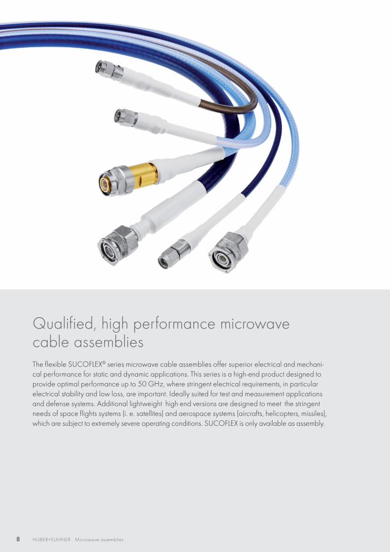
Qualified, high performance microwavecable assemblies The flexible SUCOFLEX® series microwave cable assemblies offer superior electrical and mechani-cal performance for static and dynamic applications. This series is a high-end product designed to provide optimal performance up to 50 GHz, where stringent electrical requirements, in particular electrical stability and low loss, are important. Ideally suited for test and measurement applications and defense systems. Additional lightweight high end versions are designed to meet the stringent needs of space flights systems (i. e. satellites) and aerospace systems (aircrafts, helicopters, missiles), which are subject to extremely severe operating conditions. SUCOFLEX is only available as assembly.
HUBER+SUHNER Microwave assembliesAbbreviations see page 176 9HUBER+SUHNER Microwave assemblies 9
Hig
h
perf
orm
ance
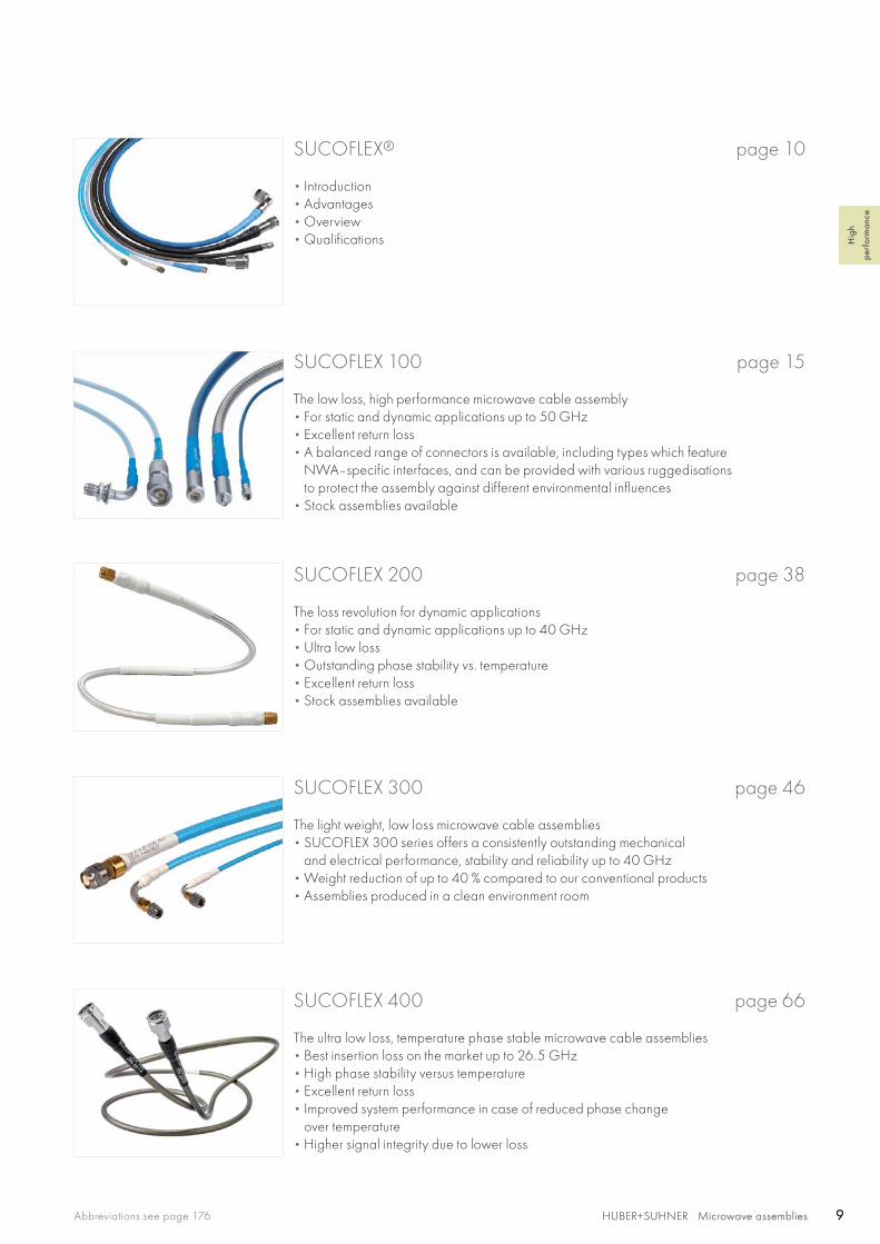
SUCOFLEX 200 page 38
The loss revolution for dynamic applications• For static and dynamic applications up to 40 GHz• Ultra low loss• Outstanding phase stability vs. temperature• Excellent return loss• Stock assemblies available
SUCOFLEX 300 page 46
The light weight, low loss microwave cable assemblies• SUCOFLEX 300 series offers a consistently outstanding mechanical
and electrical performance, stability and reliability up to 40 GHz• Weight reduction of up to 40 % compared to our conventional products• Assemblies produced in a clean environment room
SUCOFLEX 400 page 66
The ultra low loss, temperature phase stable microwave cable assemblies• Best insertion loss on the market up to 26.5 GHz• High phase stability versus temperature• Excellent return loss• Improved system performance in case of reduced phase change
over temperature• Higher signal integrity due to lower loss
SUCOFLEX 100 page 15
The low loss, high performance microwave cable assembly• For static and dynamic applications up to 50 GHz • Excellent return loss• A balanced range of connectors is available, including types which feature
NWA–specific interfaces, and can be provided with various ruggedisationsto protect the assembly against different environmental influences
• Stock assemblies available
SUCOFLEX® page 10
• Introduction• Advantages• Overview• Qualifications
HUBER+SUHNER Microwave assemblies10 HUBER+SUHNER Microwave assemblies10
Introduction SUCOFLEX®
What are SUCOFLEX assemblies?
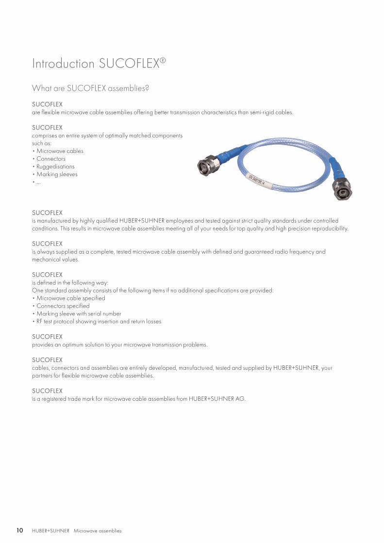
SUCOFLEXare flexible microwave cable assemblies offering better transmission characteristics than semi-rigid cables.
SUCOFLEXcomprises an entire system of optimally matched componentssuch as:• Microwave cables• Connectors • Ruggedisations• Marking sleeves• ...
SUCOFLEXis manufactured by highly qualified HUBER+SUHNER employees and tested against strict quality standards under controlled conditions. This results in microwave cable assemblies meeting all of your needs for top quality and high precision reproducibility.
SUCOFLEXis always supplied as a complete, tested microwave cable assembly with defined and guaranteed radio frequency andmechanical values.
SUCOFLEXis defined in the following way:One standard assembly consists of the following items if no additional specifications are provided:• Microwave cable specified• Connectors specified• Marking sleeve with serial number• RF test protocol showing insertion and return losses
SUCOFLEXprovides an optimum solution to your microwave transmission problems.
SUCOFLEXcables, connectors and assemblies are entirely developed, manufactured, tested and supplied by HUBER+SUHNER, yourpartners for flexible microwave cable assemblies.
SUCOFLEXis a registered trade mark for microwave cable assemblies from HUBER+SUHNER AG.
HUBER+SUHNER Microwave assembliesAbbreviations see page 176 11HUBER+SUHNER Microwave assemblies 11
Hig
h
perf
orm
ance
Advantages of SUCOFLEX®
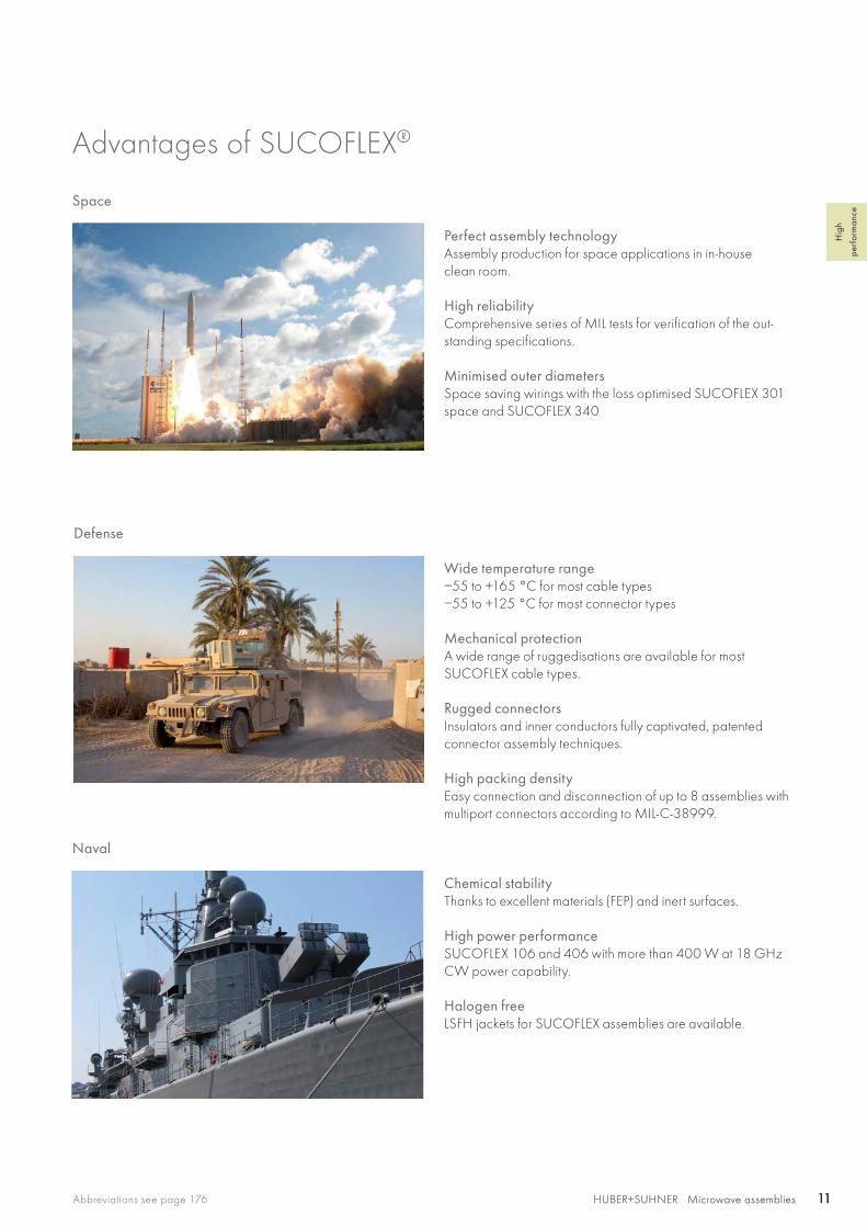
Chemical stabilityThanks to excellent materials (FEP) and inert surfaces.
High power performanceSUCOFLEX 106 and 406 with more than 400 W at 18 GHz CW power capability.
Halogen freeLSFH jackets for SUCOFLEX assemblies are available.
Naval
Space
Perfect assembly technologyAssembly production for space applications in in-houseclean room.
High reliabilityComprehensive series of MIL tests for verification of the out-standing specifications.
Minimised outer diametersSpace saving wirings with the loss optimised SUCOFLEX 301 space and SUCOFLEX 340
Wide temperature range−55 to +165 °C for most cable types−55 to +125 °C for most connector types
Mechanical protectionA wide range of ruggedisations are available for most SUCOFLEX cable types.
Rugged connectorsInsulators and inner conductors fully captivated, patented connector assembly techniques.
High packing densityEasy connection and disconnection of up to 8 assemblies with multiport connectors according to MIL-C-38999.
Defense
HUBER+SUHNER Microwave assemblies12 HUBER+SUHNER Microwave assemblies12
Advantages of SUCOFLEX®
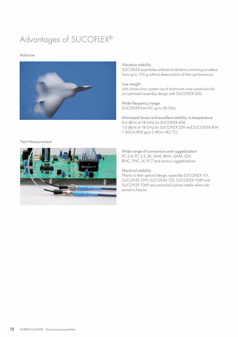
Airborne
Vibration stabilitySUCOFLEX assemblies withstand vibrations involving accelera-tions up to 100 g without deterioration of their performance.
Low weightUnit construction system use of aluminium core conductors for an optimised assembly design with SUCOFLEX 300.
Wide frequency rangeSUCOFLEX from DC up to 50 GHz
Minimised losses and excellent stability vs.temperature0.6 dB/m at 18 GHz for SUCOFLEX 406 1.0 dB/m at 18 GHz for SUCOFLEX 229 and SUCOFLEX 404< 500 to 800 ppm (−40 to +85 °C)
Wide range of connectors and ruggedisationPC 2.4, PC 3.5, SK, SMA, BMA, QMA, QN,BNC, TNC, N, PC7 and various ruggedisations
Electrical stabilityThanks to their special design, types like SUCOFLEX 101, SUCOFLEX 101P, SUCOFLEX 102, SUCOFLEX 104P and SUCOFLEX 106P are particularly phase stable when sub-jected to flexure.
Test+Measurement
HUBER+SUHNER Microwave assembliesAbbreviations see page 176 13HUBER+SUHNER Microwave assemblies 13
Hig
h
perf
orm
ance
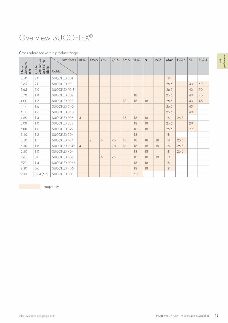
Overview SUCOFLEX®
Cross reference within product range
Out
erdi
amet
erm
m
Cab
leat
tenu
atio
nat
18
GH
z dB
/m
Interfaces
Cables
BNC QMA QN 7/16 BMA TNC N PC7 SMA PC3.5 SK PC2.4
3.50 2.0 SUCOFLEX 301 18
3.65 2.0 SUCOFLEX 101 26.5 40 50
3.65 3.0 SUCOFLEX 101P 26.5 40 50
3.70 1.9 SUCOFLEX 302 18 26.5 40 40
4.00 1.7 SUCOFLEX 102 18 18 18 26.5 40 46
4.14 1.6 SUCOFLEX 240 26.5 40
4.14 1.6 SUCOFLEX 340 26.5 40
4.60 1.3 SUCOFLEX 103 4 18 18 18 18 26.5
5.08 1.0 SUCOFLEX 229 18 18 26.5 29
5.08 1.0 SUCOFLEX 329 18 18 26.5 29
5.40 1.2 SUCOFLEX 304 18 18
5.50 1.1 SUCOFLEX 104 6 6 7.5 18 18 18 18 18 26.5
5.50 1.6 SUCOFLEX 104P 4 7.5 18 18 18 18 18 26.5
5.50 1.0 SUCOFLEX 404 18 18 18 26.5
7.90 0.8 SUCOFLEX 106 6 7.5 18 18 18 18
7.90 1.3 SUCOFLEX 106P 18 18 18
8.30 0.6 SUCOFLEX 406 18 18 18
9.00 0.34 (5.5) SUCOFLEX 307 5.5
Frequency
HUBER+SUHNER Microwave assemblies14 HUBER+SUHNER Microwave assemblies14
Summary of SUCOFLEX® qualifications
The entire SUCOFLEX family is certified to the following standards through testing, analysis or similarity.
Temperature, altitude and humidity• MIL-STD-810, method 518.1, procedure I
Thermal shock• MIL-STD-202, method 106, condition B1, 25 cycles, temperature: −54 to 125 °C
Mechanical shock• MIL-STD-810, method 516.3, procedure I (half-sine), 20 g, 6 to 9 ms, 45 Hz cross over frequency• MIL-STD-810, method 516, procedure I (saw-tooth), 40 g saw-tooth pulse of 11 ms duration 3 shocks in each of the six directions
Vibration• MIL-STD-810, method 519.3, procedure I, figure 514.3-1, (gunfire), 26.5 min. with specified vibration profile• MIL-STD-810, method 514.3, procedure I (random), functional: 0.2 g2/Hz, endurance: 0.83 g2/Hz• MIL-STD-202; method 204, condition G (sinusoidal), acceleration: 30 g, frequency range: 10 to 2000 Hz,
duration: 4 hours in each of three axes
Acceleration• MIL-STD-810, method 513.3, procedure II, 27 g, 5 min.• MIL-STD-810, method 513.3, procedure I, 50 g, 5 min.
Chemical resistance• British standard 3G100, part 2, section 3, class A
Moisture resistance• MIL-STD-202, method 106, 10 day exposure
Salt fog• MIL-STD-810, method 509.2, 48 hours exposure to a 5 % solution
Fungus• MIL-STD-810, method 508.3
Sand and dust• Def. stand. 07-55, part 2, section 4, issue 1, +35 °C, 3 hours
Solar radiation• MIL-STD-810, method 505, procedure II
HUBER+SUHNER Microwave assembliesAbbreviations see page 176 15HUBER+SUHNER Microwave assemblies 15
Hig
h
perf
orm
ance
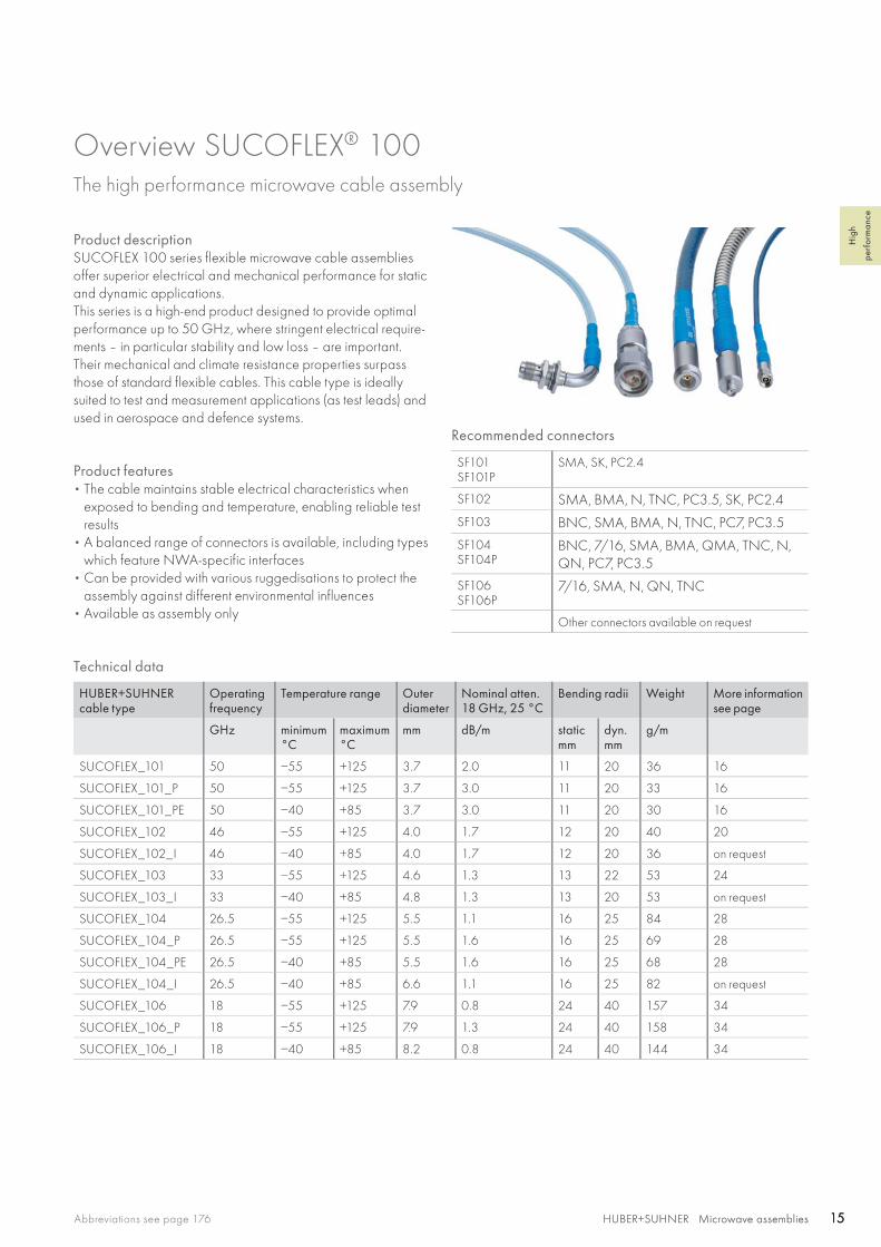
Overview SUCOFLEX® 100The high performance microwave cable assembly
Product descriptionSUCOFLEX 100 series flexible microwave cable assemblies offer superior electrical and mechanical performance for static and dynamic applications.This series is a high-end product designed to provide optimal performance up to 50 GHz, where stringent electrical require-ments – in particular stability and low loss – are important. Their mechanical and climate resistance properties surpass those of standard flexible cables. This cable type is ideally suited to test and measurement applications (as test leads) and used in aerospace and defence systems.
Product features• The cable maintains stable electrical characteristics when
exposed to bending and temperature, enabling reliable test results
• A balanced range of connectors is available, including types which feature NWA-specific interfaces
• Can be provided with various ruggedisations to protect the assembly against different environmental influences
• Available as assembly only
Recommended connectors
SF101SF101P
SMA, SK, PC2.4
SF102 SMA, BMA, N, TNC, PC3.5, SK, PC2.4
SF103 BNC, SMA, BMA, N, TNC, PC7, PC3.5
SF104SF104P
BNC, 7/16, SMA, BMA, QMA, TNC, N, QN, PC7, PC3.5
SF106SF106P
7/16, SMA, N, QN, TNC
Other connectors available on request
Technical data
HUBER+SUHNER cable type
Operating frequency
Temperature range Outer diameter
Nominal atten.18 GHz, 25 °C
Bending radii Weight More information see page
GHz minimum°C
maximum°C
mm dB/m static mm
dyn.mm
g/m
SUCOFLEX_101 50 −55 +125 3.7 2.0 11 20 36 16
SUCOFLEX_101_P 50 −55 +125 3.7 3.0 11 20 33 16
SUCOFLEX_101_PE 50 −40 +85 3.7 3.0 11 20 30 16
SUCOFLEX_102 46 −55 +125 4.0 1.7 12 20 40 20
SUCOFLEX_102_I 46 −40 +85 4.0 1.7 12 20 36 on request
SUCOFLEX_103 33 −55 +125 4.6 1.3 13 22 53 24
SUCOFLEX_103_I 33 −40 +85 4.8 1.3 13 20 53 on request
SUCOFLEX_104 26.5 −55 +125 5.5 1.1 16 25 84 28
SUCOFLEX_104_P 26.5 −55 +125 5.5 1.6 16 25 69 28
SUCOFLEX_104_PE 26.5 −40 +85 5.5 1.6 16 25 68 28
SUCOFLEX_104_I 26.5 −40 +85 6.6 1.1 16 25 82 on request
SUCOFLEX_106 18 −55 +125 7.9 0.8 24 40 157 34
SUCOFLEX_106_P 18 −55 +125 7.9 1.3 24 40 158 34
SUCOFLEX_106_I 18 −40 +85 8.2 0.8 24 40 144 34
SF 101/101E/101P, 104PE SF 101EA/PEA
HUBER+SUHNER Microwave assemblies16 HUBER+SUHNER Microwave assemblies16
SUCOFLEX® 101 The high performance microwave cable assembly working up to 50 GHz
Product descriptionThe SUCOFLEX 101 high end cable assemblies are designed to provide optimal performance up to 50 GHz were stringent electrical requirements – in particular stability and low loss, are important. Their mechanical and climate resistance properties surpass those of standard flexible cable. Additionally protected by an A ruggedisation, the SUCOFLEX 101PE becomes a flexible test and measurement cable up to 50 GHz!
Product features• Impedance 50 Ω • Applicable up to 50 GHz• High stability and low loss• Wide range of connectors• VNA-specific connectors
Recommended connectors
SF101SF101P
SMA, SK, PC2.4
Other connectors available on request
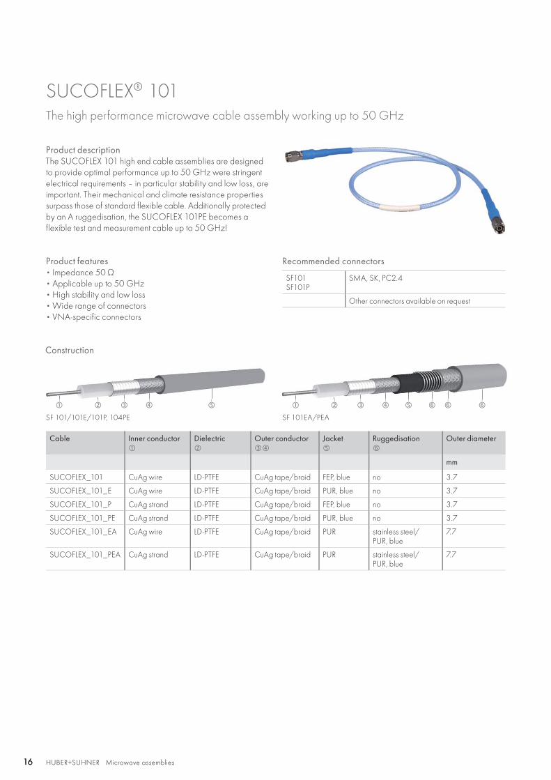
Construction
Cable Inner conductor
Dielectric
Outer conductor
Jacket
Ruggedisation
Outer diameter
mm
SUCOFLEX_101 CuAg wire LD-PTFE CuAg tape/braid FEP, blue no 3.7
SUCOFLEX_101_E CuAg wire LD-PTFE CuAg tape/braid PUR, blue no 3.7
SUCOFLEX_101_P CuAg strand LD-PTFE CuAg tape/braid FEP, blue no 3.7
SUCOFLEX_101_PE CuAg strand LD-PTFE CuAg tape/braid PUR, blue no 3.7
SUCOFLEX_101_EA CuAg wire LD-PTFE CuAg tape/braid PUR stainless steel/PUR, blue
7.7
SUCOFLEX_101_PEA CuAg strand LD-PTFE CuAg tape/braid PUR stainless steel/PUR, blue
7.7
HUBER+SUHNER Microwave assembliesAbbreviations see page 176 17HUBER+SUHNER Microwave assemblies 17
Hig
h
perf
orm
ance
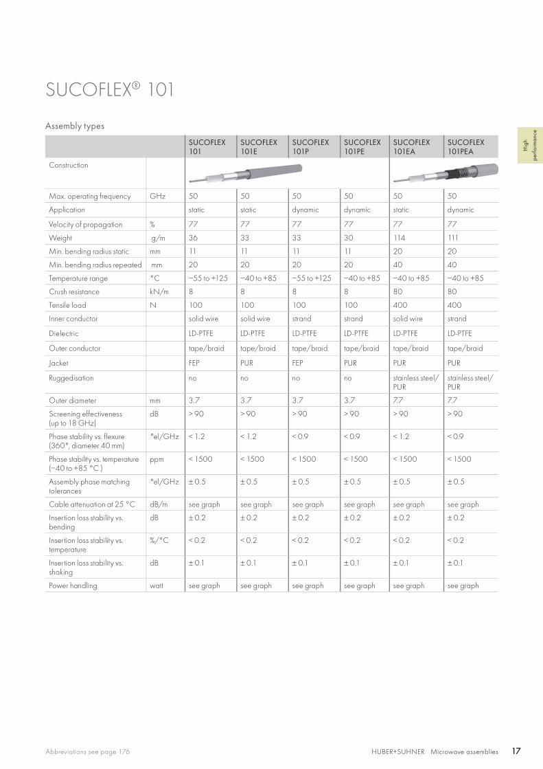
SUCOFLEX® 101
Assembly types
SUCOFLEX 101
SUCOFLEX 101E
SUCOFLEX 101P
SUCOFLEX 101PE
SUCOFLEX 101EA
SUCOFLEX 101PEA
Construction
Max. operating frequency GHz 50 50 50 50 50 50
Application static static dynamic dynamic static dynamic
Velocity of propagation % 77 77 77 77 77 77
Weight g/m 36 33 33 30 114 111
Min. bending radius static mm 11 11 11 11 20 20
Min. bending radius repeated mm 20 20 20 20 40 40
Temperature range °C −55 to +125 −40 to +85 −55 to +125 −40 to +85 −40 to +85 −40 to +85
Crush resistance kN/m 8 8 8 8 80 80
Tensile load N 100 100 100 100 400 400
Inner conductor solid wire solid wire strand strand solid wire strand
Dielectric LD-PTFE LD-PTFE LD-PTFE LD-PTFE LD-PTFE LD-PTFE
Outer conductor tape/braid tape/braid tape/braid tape/braid tape/braid tape/braid
Jacket FEP PUR FEP PUR PUR PUR
Ruggedisation no no no no stainless steel/PUR
stainless steel/PUR
Outer diameter mm 3.7 3.7 3.7 3.7 7.7 7.7
Screening effectiveness(up to 18 GHz)
dB > 90 > 90 > 90 > 90 > 90 > 90
Phase stability vs. flexure (360°, diameter 40 mm)
°el/GHz < 1.2 < 1.2 < 0.9 < 0.9 < 1.2 < 0.9
Phase stability vs. temperature (−40 to +85 °C )
ppm < 1500 < 1500 < 1500 < 1500 < 1500 < 1500
Assembly phase matching tolerances
°el/GHz ± 0.5 ± 0.5 ± 0.5 ± 0.5 ± 0.5 ± 0.5
Cable attenuation at 25 °C dB/m see graph see graph see graph see graph see graph see graph
Insertion loss stability vs. bending
dB ± 0.2 ± 0.2 ± 0.2 ± 0.2 ± 0.2 ± 0.2
Insertion loss stability vs. temperature
%/°C < 0.2 < 0.2 < 0.2 < 0.2 < 0.2 < 0.2
Insertion loss stability vs. shaking
dB ± 0.1 ± 0.1 ± 0.1 ± 0.1 ± 0.1 ± 0.1
Power handling watt see graph see graph see graph see graph see graph see graph
0 2 4 6 8 10 12 14 16 18 20 22 24 26 28 30 32 34 36 38 40 42 44 46 48 50
0 2 4 6 8 10 12 14 16 18 20 22 24 26 28 30 32 34 36 38 40 42 44 46 48 50
SF 101SF 101ESF 101EASF 101PSF101PESF101PEA
SF 101SF 101ESF 101EASF 101PSF101PESF101PEA
6
5
4
3
2
1
0
150
200
250
300
350
400
100
50
0
HUBER+SUHNER Microwave assemblies18 HUBER+SUHNER Microwave assemblies18
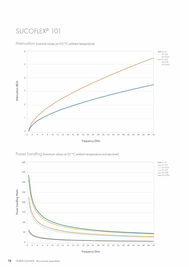
SUCOFLEX® 101
Attenuation (nominal values at +25 °C ambient temperature)
Power handling (maximum values at 25 °C ambient temperature and sea level)
Atte
nuat
ion
dB/m
Pow
er h
andl
ing
Wat
ts
Frequency GHz
Frequency GHz

HUBER+SUHNER Microwave assembliesAbbreviations see page 176 19HUBER+SUHNER Microwave assemblies 19
Hig
h
perf
orm
ance
SUCOFLEX® 101
Stock assemblies
Item no. Type Length Frequency Max. insertion loss at 25 °C
Max.VSWR
RoHS compliant
mm GHz dB
SUCOFLEX_101
85026753 SF101/PC24m/PC24m/500 mm 500 50 2.29 1.44 yes
SUCOFLEX_101_EA (armoured)
85026754 SF101EA/PC24m/PC24m/500 mm 500 50 2.29 1.44 yes
Available connectors
Connector Series, pattern HUBER+SUHNERconnector type
SF101SF101E
SF101EA SF101PSF101PE
SF101PEA Op. freq.
VSWRperconnector
Remarks
GHz
DV straight cable plug 11_DV-112 • 50 1.20 2.4 mm connector for Agilent Technologies Instrument
SK straight cable plug 11_SK-100 • 40 1.20
straight cable plug 11_SK-110 • 40 1.20
straight cable jack 21_SK-110 • 40 1.20
PC 2.4 straight cable plug 11_PC2.4-104 • 50 1.20
straight cable plug 11_PC2.4-107 • 50 1.20
straight cable plug 11_PC2.4-109 • 50 1.20
straight cable plug 11_PC2.4-110 • 50 1.20
straight cable jack 21_PC2.4-104 • 50 1.20
straight cable jack 21_PC2.4-107 • 50 1.20
straight cable jack 21_PC2.4-109 • 50 1.20
straight cable jack 21_PC2.4-110 • 50 1.20
straight panel bulkhead cable jack
24_PC2.4-102 • 50 1.20 ML 38
SMA straight cable plug 11_SMA-153 • 1826.5
1.121.20
straight cable plug 11_SMA-190 • 1826.5
SF 102/102E
SF 102EA
SF 102D
HUBER+SUHNER Microwave assemblies20 HUBER+SUHNER Microwave assemblies20
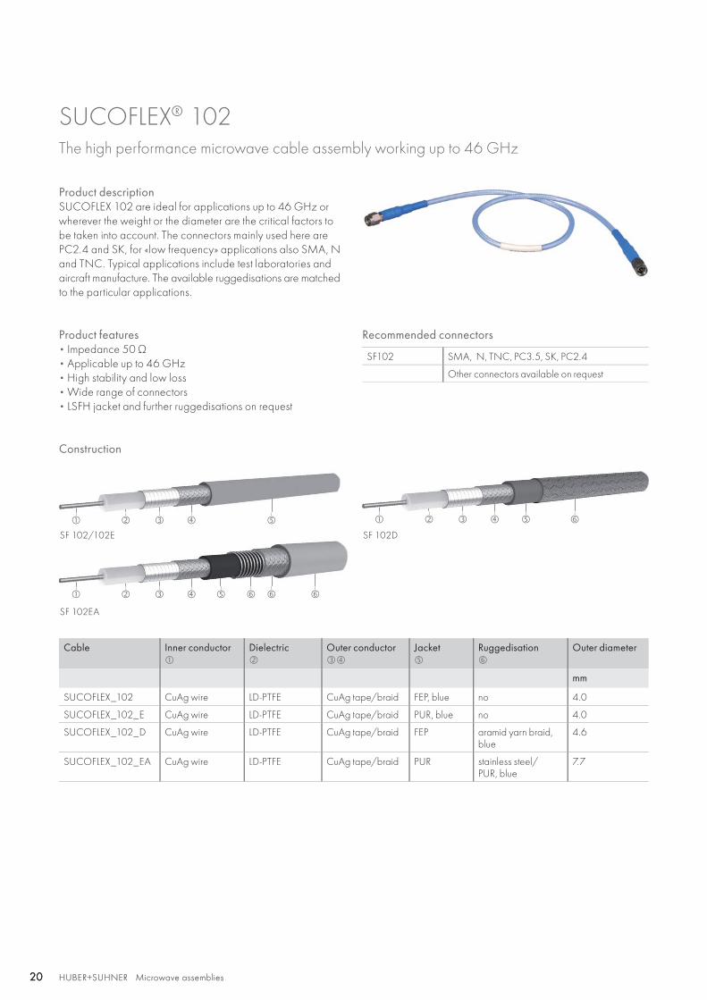
SUCOFLEX® 102 The high performance microwave cable assembly working up to 46 GHz
Product descriptionSUCOFLEX 102 are ideal for applications up to 46 GHz or wherever the weight or the diameter are the critical factors to be taken into account. The connectors mainly used here are PC2.4 and SK, for «low frequency» applications also SMA, N and TNC. Typical applications include test laboratories and aircraft manufacture. The available ruggedisations are matched to the particular applications.
Product features• Impedance 50 Ω • Applicable up to 46 GHz• High stability and low loss• Wide range of connectors• LSFH jacket and further ruggedisations on request
Recommended connectors
SF102 SMA, N, TNC, PC3.5, SK, PC2.4
Other connectors available on request
Cable Inner conductor
Dielectric
Outer conductor
Jacket
Ruggedisation
Outer diameter
mm
SUCOFLEX_102 CuAg wire LD-PTFE CuAg tape/braid FEP, blue no 4.0
SUCOFLEX_102_E CuAg wire LD-PTFE CuAg tape/braid PUR, blue no 4.0
SUCOFLEX_102_D CuAg wire LD-PTFE CuAg tape/braid FEP aramid yarn braid, blue
4.6
SUCOFLEX_102_EA CuAg wire LD-PTFE CuAg tape/braid PUR stainless steel/PUR, blue
7.7
Construction
HUBER+SUHNER Microwave assembliesAbbreviations see page 176 21HUBER+SUHNER Microwave assemblies 21
Hig
h
perf
orm
ance
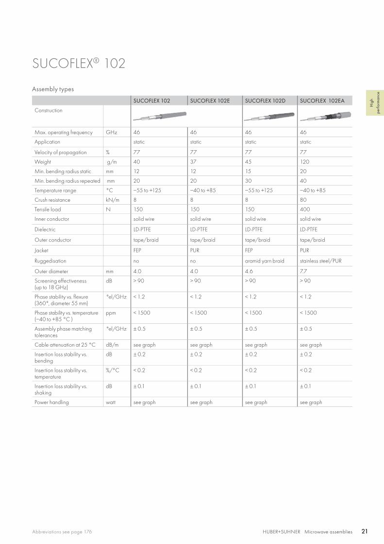
SUCOFLEX® 102
Assembly types
SUCOFLEX 102 SUCOFLEX 102E SUCOFLEX 102D SUCOFLEX 102EA
Construction
Max. operating frequency GHz 46 46 46 46
Application static static static static
Velocity of propagation % 77 77 77 77
Weight g/m 40 37 45 120
Min. bending radius static mm 12 12 15 20
Min. bending radius repeated mm 20 20 30 40
Temperature range °C −55 to +125 −40 to +85 −55 to +125 −40 to +85
Crush resistance kN/m 8 8 8 80
Tensile load N 150 150 150 400
Inner conductor solid wire solid wire solid wire solid wire
Dielectric LD-PTFE LD-PTFE LD-PTFE LD-PTFE
Outer conductor tape/braid tape/braid tape/braid tape/braid
Jacket FEP PUR FEP PUR
Ruggedisation no no aramid yarn braid stainless steel/PUR
Outer diameter mm 4.0 4.0 4.6 7.7
Screening effectiveness(up to 18 GHz)
dB > 90 > 90 > 90 > 90
Phase stability vs. flexure (360°, diameter 55 mm)
°el/GHz < 1.2 < 1.2 < 1.2 < 1.2
Phase stability vs. temperature (−40 to +85 °C )
ppm < 1500 < 1500 < 1500 < 1500
Assembly phase matching tolerances
°el/GHz ± 0.5 ± 0.5 ± 0.5 ± 0.5
Cable attenuation at 25 °C dB/m see graph see graph see graph see graph
Insertion loss stability vs. bending
dB ± 0.2 ± 0.2 ± 0.2 ± 0.2
Insertion loss stability vs. temperature
%/°C < 0.2 < 0.2 < 0.2 < 0.2
Insertion loss stability vs. shaking
dB ± 0.1 ± 0.1 ± 0.1 ± 0.1
Power handling watt see graph see graph see graph see graph
0 2 4 6 8 10 12 14 16 18 20 22 24 26 28 30 32 34 36 38 40 42 44 46
0 2 4 6 8 10 12 14 16 18 20 22 24 26 28 30 32 34 36 38 40 42 44 46
2.5
1.5
0.5
150
200
250
300
350
400
450
500
100
50
0
SF 102SF 102DSF 102ESF 102EA
SF 102SF 102DSF 102ESF 102EA
3
2
1
0
HUBER+SUHNER Microwave assemblies22 HUBER+SUHNER Microwave assemblies22
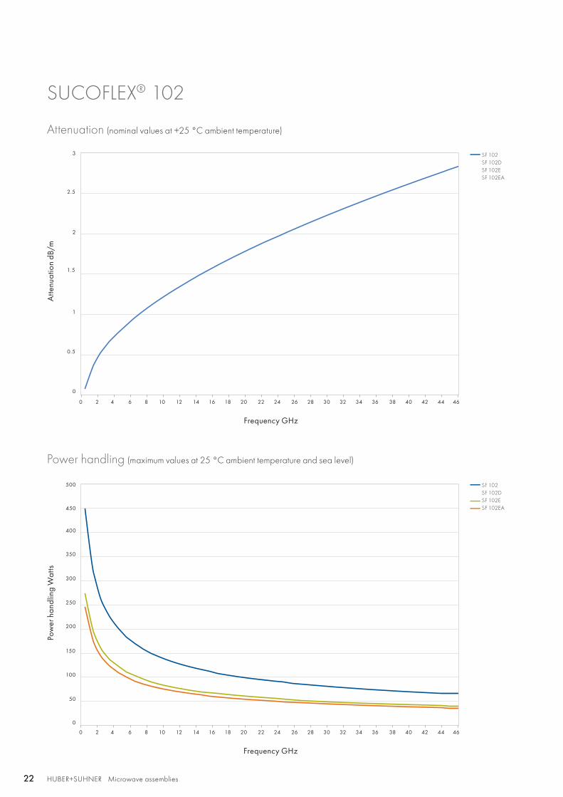
SUCOFLEX® 102
Attenuation (nominal values at +25 °C ambient temperature)
Power handling (maximum values at 25 °C ambient temperature and sea level)
Atte
nuat
ion
dB/m
Pow
er h
andl
ing
Wat
ts
Frequency GHz
Frequency GHz
HUBER+SUHNER Microwave assembliesAbbreviations see page 176 23HUBER+SUHNER Microwave assemblies 23
Hig
h
perf
orm
ance
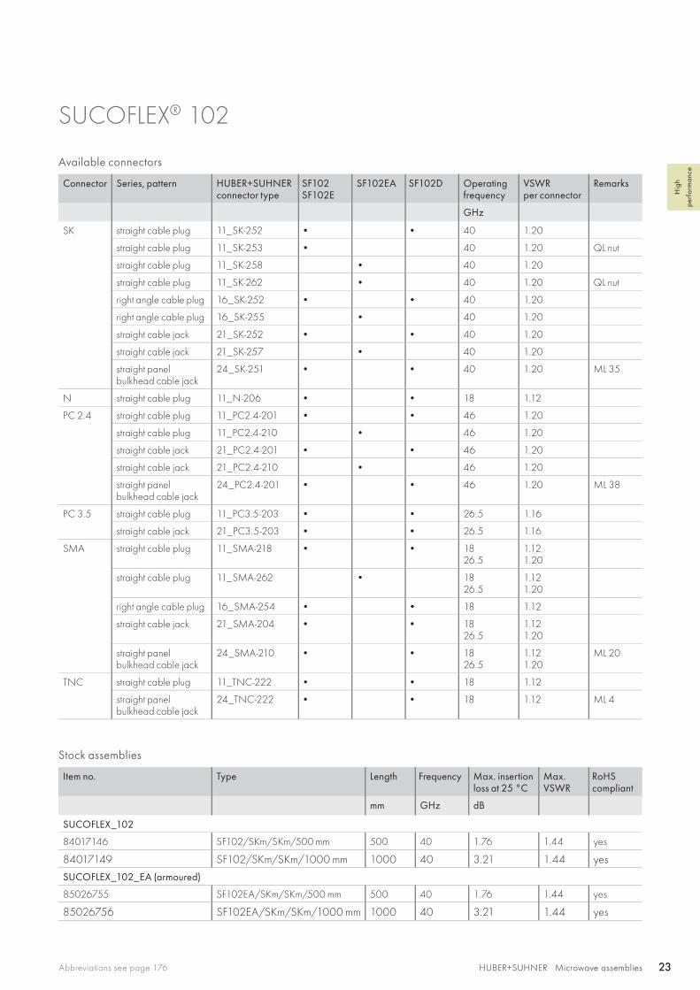
SUCOFLEX® 102
Stock assemblies
Item no. Type Length Frequency Max. insertion loss at 25 °C
Max.VSWR
RoHS compliant
mm GHz dB
SUCOFLEX_102
84017146 SF102/SKm/SKm/500 mm 500 40 1.76 1.44 yes
84017149 SF102/SKm/SKm/1000 mm 1000 40 3.21 1.44 yes
SUCOFLEX_102_EA (armoured)
85026755 SF102EA/SKm/SKm/500 mm 500 40 1.76 1.44 yes
85026756 SF102EA/SKm/SKm/1000 mm 1000 40 3.21 1.44 yes
Available connectors
Connector Series, pattern HUBER+SUHNERconnector type
SF102SF102E
SF102EA SF102D Operating frequency
VSWRper connector
Remarks
GHz
SK straight cable plug 11_SK-252 • • 40 1.20
straight cable plug 11_SK-253 • 40 1.20 QL nut
straight cable plug 11_SK-258 • 40 1.20
straight cable plug 11_SK-262 • 40 1.20 QL nut
right angle cable plug 16_SK-252 • • 40 1.20
right angle cable plug 16_SK-255 • 40 1.20
straight cable jack 21_SK-252 • • 40 1.20
straight cable jack 21_SK-257 • 40 1.20
straight panel bulkhead cable jack
24_SK-251 • • 40 1.20 ML 35
N straight cable plug 11_N-206 • • 18 1.12
PC 2.4 straight cable plug 11_PC2.4-201 • • 46 1.20
straight cable plug 11_PC2.4-210 • 46 1.20
straight cable jack 21_PC2.4-201 • • 46 1.20
straight cable jack 21_PC2.4-210 • 46 1.20
straight panel bulkhead cable jack
24_PC2.4-201 • • 46 1.20 ML 38
PC 3.5 straight cable plug 11_PC3.5-203 • • 26.5 1.16
straight cable jack 21_PC3.5-203 • • 26.5 1.16
SMA straight cable plug 11_SMA-218 • • 1826.5
1.121.20
straight cable plug 11_SMA-262 • 1826.5
1.121.20
right angle cable plug 16_SMA-254 • • 18 1.12
straight cable jack 21_SMA-204 • • 1826.5
1.121.20
straight panel bulkhead cable jack
24_SMA-210 • • 1826.5
1.121.20
ML 20
TNC straight cable plug 11_TNC-222 • • 18 1.12
straight panel bulkhead cable jack
24_TNC-222 • • 18 1.12 ML 4
SF 103/103E
SF 103EA
SF 103D
HUBER+SUHNER Microwave assemblies24 HUBER+SUHNER Microwave assemblies24
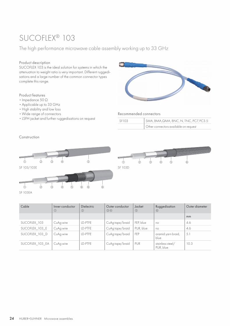
SUCOFLEX® 103 The high performance microwave cable assembly working up to 33 GHz
Product descriptionSUCOFLEX 103 is the ideal solution for systems in which the attenuation to weight ratio is very important. Different ruggedi-sations and a large number of the common connector types complete this range.
Product features• Impedance 50 Ω • Applicable up to 33 GHz• High stability and low loss• Wide range of connectors• LSFH jacket and further ruggedisations on request
Recommended connectors
SF103 SMA, BMA,QMA, BNC, N, TNC, PC7, PC3.5
Other connectors available on request
Cable Inner conductor
Dielectric
Outer conductor
Jacket
Ruggedisation
Outer diameter
mm
SUCOFLEX_103 CuAg wire LD-PTFE CuAg tape/braid FEP, blue no 4.6
SUCOFLEX_103_E CuAg wire LD-PTFE CuAg tape/braid PUR, blue no 4.6
SUCOFLEX_103_D CuAg wire LD-PTFE CuAg tape/braid FEP aramid yarn braid, blue
5.1
SUCOFLEX_103_EA CuAg wire LD-PTFE CuAg tape/braid PUR stainless steel/PUR, blue
10.3
Construction
HUBER+SUHNER Microwave assembliesAbbreviations see page 176 25HUBER+SUHNER Microwave assemblies 25
Hig
h
perf
orm
ance
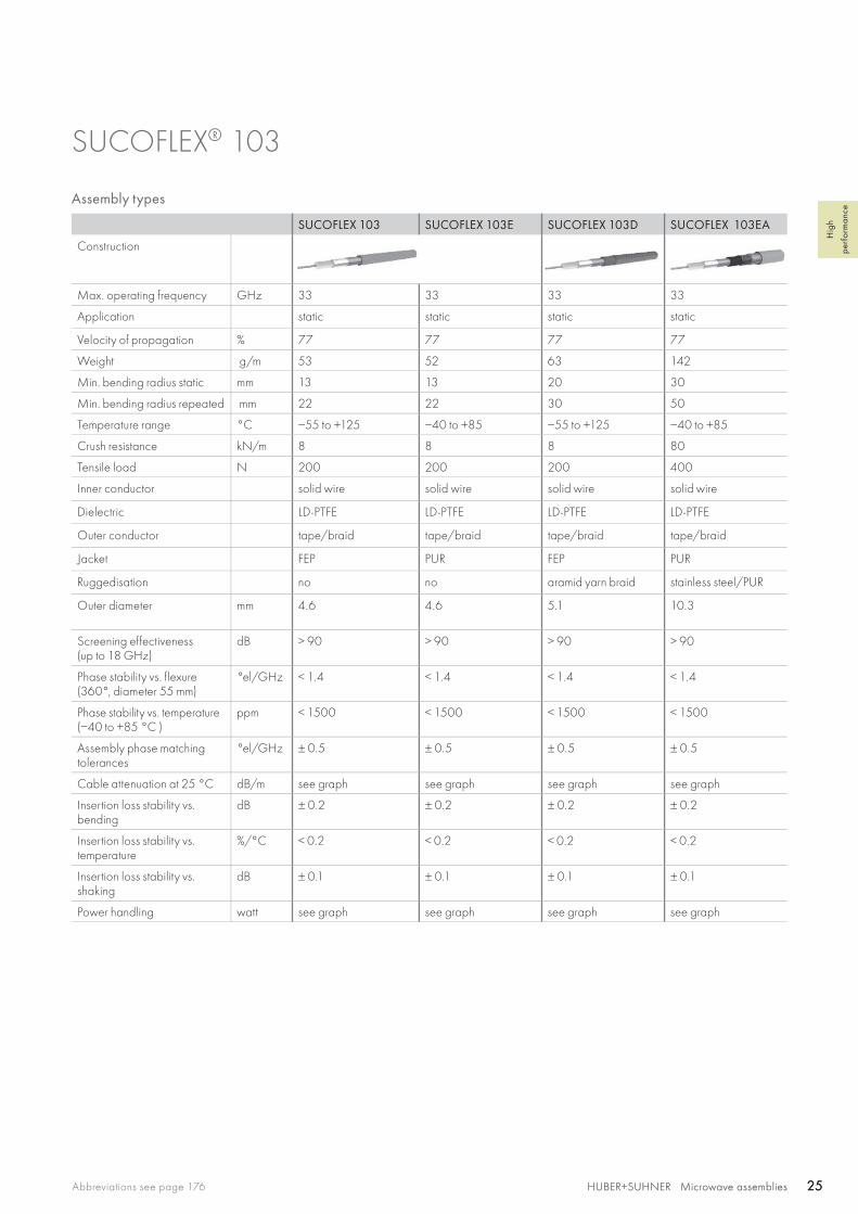
SUCOFLEX® 103
Assembly types
SUCOFLEX 103 SUCOFLEX 103E SUCOFLEX 103D SUCOFLEX 103EA
Construction
Max. operating frequency GHz 33 33 33 33
Application static static static static
Velocity of propagation % 77 77 77 77
Weight g/m 53 52 63 142
Min. bending radius static mm 13 13 20 30
Min. bending radius repeated mm 22 22 30 50
Temperature range °C −55 to +125 −40 to +85 −55 to +125 −40 to +85
Crush resistance kN/m 8 8 8 80
Tensile load N 200 200 200 400
Inner conductor solid wire solid wire solid wire solid wire
Dielectric LD-PTFE LD-PTFE LD-PTFE LD-PTFE
Outer conductor tape/braid tape/braid tape/braid tape/braid
Jacket FEP PUR FEP PUR
Ruggedisation no no aramid yarn braid stainless steel/PUR
Outer diameter mm 4.6 4.6 5.1 10.3
Screening effectiveness(up to 18 GHz)
dB > 90 > 90 > 90 > 90
Phase stability vs. flexure (360°, diameter 55 mm)
°el/GHz < 1.4 < 1.4 < 1.4 < 1.4
Phase stability vs. temperature (−40 to +85 °C )
ppm < 1500 < 1500 < 1500 < 1500
Assembly phase matching tolerances
°el/GHz ± 0.5 ± 0.5 ± 0.5 ± 0.5
Cable attenuation at 25 °C dB/m see graph see graph see graph see graph
Insertion loss stability vs. bending
dB ± 0.2 ± 0.2 ± 0.2 ± 0.2
Insertion loss stability vs. temperature
%/°C < 0.2 < 0.2 < 0.2 < 0.2
Insertion loss stability vs. shaking
dB ± 0.1 ± 0.1 ± 0.1 ± 0.1
Power handling watt see graph see graph see graph see graph
0 1 2 3 4 5 6 7 8 9 10 11 12 13 14 15 16 17 18 19 20 21 22 23 24 25 26 27 28 29 30 31 32 33
0 1 2 3 4 5 6 7 8 9 10 11 12 13 14 15 16 17 18 19 20 21 22 23 24 25 26 27 28 29 30 31 32 33
0.8
1
2
1.2
1.4
1.6
1.8
0.2
0.4
0.6
0
200
300
400
500
600
700
800
100
0
SF 103SF 103DSF 103ESF 103EA
SF 103SF 103DSF 103ESF 103EA
HUBER+SUHNER Microwave assemblies26 HUBER+SUHNER Microwave assemblies26
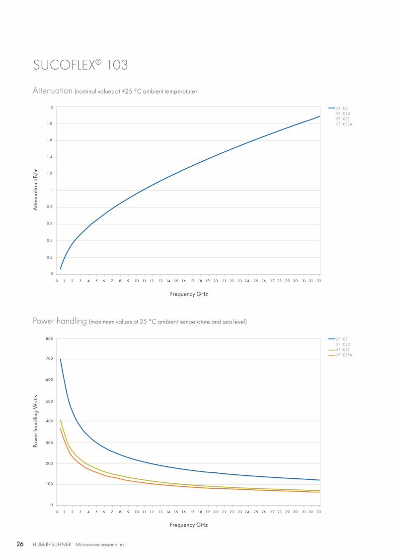
SUCOFLEX® 103
Attenuation (nominal values at +25 °C ambient temperature)
Power handling (maximum values at 25 °C ambient temperature and sea level)
Atte
nuat
ion
dB/m
Pow
er h
andl
ing
Wat
ts
Frequency GHz
Frequency GHz
HUBER+SUHNER Microwave assembliesAbbreviations see page 176 27HUBER+SUHNER Microwave assemblies 27
Hig
h
perf
orm
ance
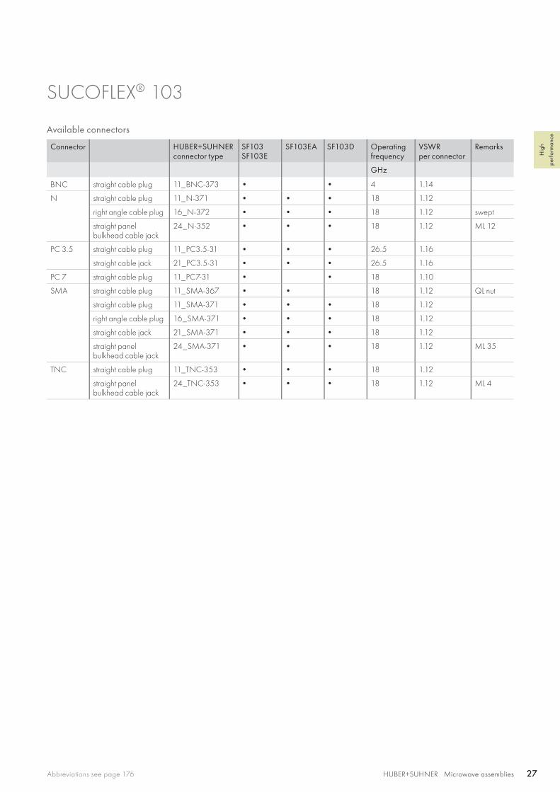
SUCOFLEX® 103
Available connectors
Connector HUBER+SUHNERconnector type
SF103SF103E
SF103EA SF103D Operatingfrequency
VSWRper connector
Remarks
GHz
BNC straight cable plug 11_BNC-373 • • 4 1.14
N straight cable plug 11_N-371 • • • 18 1.12
right angle cable plug 16_N-372 • • • 18 1.12 swept
straight panel bulkhead cable jack
24_N-352 • • • 18 1.12 ML 12
PC 3.5 straight cable plug 11_PC3.5-31 • • • 26.5 1.16
straight cable jack 21_PC3.5-31 • • • 26.5 1.16
PC 7 straight cable plug 11_PC7-31 • • 18 1.10
SMA straight cable plug 11_SMA-367 • • 18 1.12 QL nut
straight cable plug 11_SMA-371 • • • 18 1.12
right angle cable plug 16_SMA-371 • • • 18 1.12
straight cable jack 21_SMA-371 • • • 18 1.12
straight panel bulkhead cable jack
24_SMA-371 • • • 18 1.12 ML 35
TNC straight cable plug 11_TNC-353 • • • 18 1.12
straight panel bulkhead cable jack
24_TNC-353 • • • 18 1.12 ML 4

SF 104/104E/104P/104PE
SF 104PBSF 104PEA
SF 104D
HUBER+SUHNER Microwave assemblies28 HUBER+SUHNER Microwave assemblies28
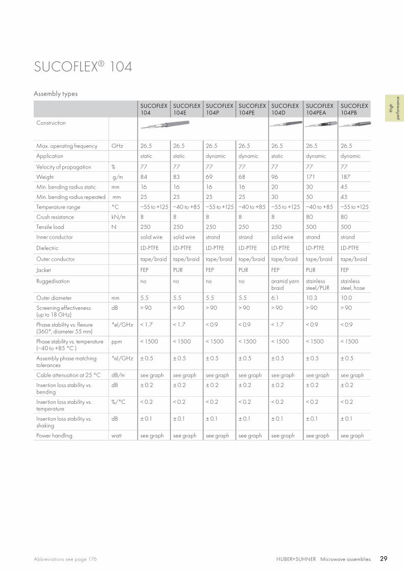
SUCOFLEX® 104 The high performance microwave cable assembly working up to 26.5 GHz
Product descriptionSUCOFLEX 104, 104P cables that can be universally assembled with the widest range of connector types, are available with most ruggedisations. In applications in which flexibility is the critical factor, the cable type SUCOFLEX 104PE must be applied.
Product features• Impedance 50 Ω • Applicable up to 26.5 GHz• High stability and low loss• Wide range of connectors• VNA-specific connectors• Quick lock nuts• LSFH jacket and further ruggedisations on request
Recommended connectors
SF104 SF104P
SMA, BMA, QMA, BNC, TNC, N, QN, 7/16, PC3.5
Other connectors available on request
Cable Inner conductor
Dielectric
Outer conductor
Jacket
Ruggedisation
Outer diameter
mm
SUCOFLEX_104 CuAg wire LD-PTFE CuAg tape/braid FEP, blue no 5.5
SUCOFLEX_104_E CuAg wire LD-PTFE CuAg tape/braid PUR, blue no 5.5
SUCOFLEX_104_D CuAg wire LD-PTFE CuAg tape/braid FEP aramid yarn braid, blue
6.1
SUCOFLEX_104_P CuAg strand LD-PTFE CuAg tape/braid FEP, blue no 5.5
SUCOFLEX_104_PE CuAg strand LD-PTFE CuAg tape/braid PUR, blue no 5.5
SUCOFLEX_104_PEA CuAg strand LD-PTFE CuAg tape/braid PUR stainless steel/PUR, blue
10.3
SUCOFLEX_104_PB CuAg strand LD-PTFE CuAg tape/braid FEP stainless steel, hose 10.0
Construction
HUBER+SUHNER Microwave assembliesAbbreviations see page 176 29HUBER+SUHNER Microwave assemblies 29
Hig
h
perf
orm
ance
SUCOFLEX® 104
Assembly types
SUCOFLEX 104
SUCOFLEX 104E
SUCOFLEX 104P
SUCOFLEX 104PE
SUCOFLEX 104D
SUCOFLEX 104PEA
SUCOFLEX 104PB
Construction
Max. operating frequency GHz 26.5 26.5 26.5 26.5 26.5 26.5 26.5
Application static static dynamic dynamic static dynamic dynamic
Velocity of propagation % 77 77 77 77 77 77 77
Weight g/m 84 83 69 68 96 171 187
Min. bending radius static mm 16 16 16 16 20 30 45
Min. bending radius repeated mm 25 25 25 25 30 50 45
Temperature range °C −55 to +125 −40 to +85 −55 to +125 −40 to +85 −55 to +125 −40 to +85 −55 to +125
Crush resistance kN/m 8 8 8 8 8 80 80
Tensile load N 250 250 250 250 250 500 500
Inner conductor solid wire solid wire strand strand solid wire strand strand
Dielectric LD-PTFE LD-PTFE LD-PTFE LD-PTFE LD-PTFE LD-PTFE LD-PTFE
Outer conductor tape/braid tape/braid tape/braid tape/braid tape/braid tape/braid tape/braid
Jacket FEP PUR FEP PUR FEP PUR FEP
Ruggedisation no no no no aramid yarn braid
stainless steel/PUR
stainless steel, hose
Outer diameter mm 5.5 5.5 5.5 5.5 6.1 10.3 10.0
Screening effectiveness(up to 18 GHz)
dB > 90 > 90 > 90 > 90 > 90 > 90 > 90
Phase stability vs. flexure (360°, diameter 55 mm)
°el/GHz < 1.7 < 1.7 < 0.9 < 0.9 < 1.7 < 0.9 < 0.9
Phase stability vs. temperature (−40 to +85 °C )
ppm < 1500 < 1500 < 1500 < 1500 < 1500 < 1500 < 1500
Assembly phase matching tolerances
°el/GHz ± 0.5 ± 0.5 ± 0.5 ± 0.5 ± 0.5 ± 0.5 ± 0.5
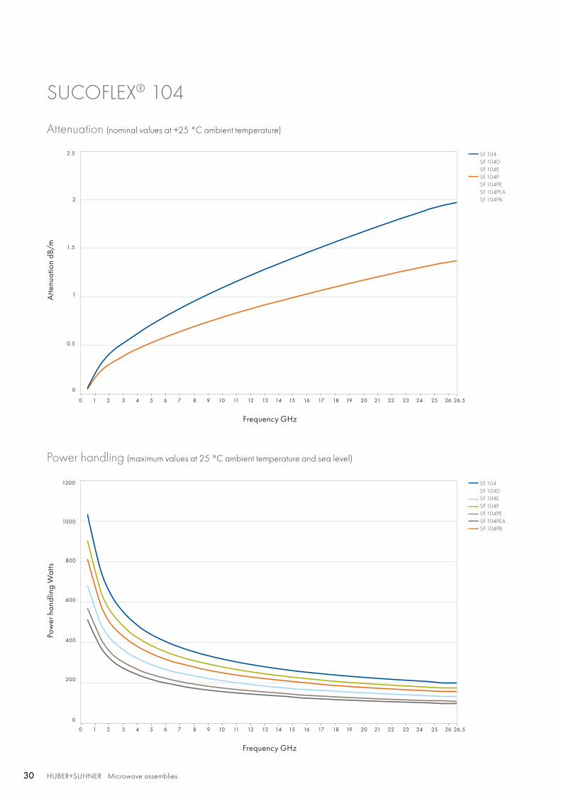
Cable attenuation at 25 °C dB/m see graph see graph see graph see graph see graph see graph see graph
Insertion loss stability vs. bending
dB ± 0.2 ± 0.2 ± 0.2 ± 0.2 ± 0.2 ± 0.2 ± 0.2
Insertion loss stability vs. temperature
%/°C < 0.2 < 0.2 < 0.2 < 0.2 < 0.2 < 0.2 < 0.2
Insertion loss stability vs. shaking
dB ± 0.1 ± 0.1 ± 0.1 ± 0.1 ± 0.1 ± 0.1 ± 0.1
Power handling watt see graph see graph see graph see graph see graph see graph see graph
0 1 2 3 4 5 6 7 8 9 10 11 12 13 14 15 16 17 18 19 20 21 22 23 24 25 26 26.5
0 1 2 3 4 5 6 7 8 9 10 11 12 13 14 15 16 17 18 19 20 21 22 23 24 25 26 26.5
SF 104SF 104DSF 104ESF 104PSF 104PESF 104PEASF 104PB
SF 104SF 104DSF 104ESF 104PSF 104PESF 104PEASF 104PB
1
2
1.5
2.5
0.5
0
200
400
600
800
1000
1200
0
HUBER+SUHNER Microwave assemblies30 HUBER+SUHNER Microwave assemblies30
SUCOFLEX® 104
Attenuation (nominal values at +25 °C ambient temperature)
Power handling (maximum values at 25 °C ambient temperature and sea level)
Atte
nuat
ion
dB/m
Pow
er h
andl
ing
Wat
ts
Frequency GHz
Frequency GHz
HUBER+SUHNER Microwave assembliesAbbreviations see page 176 31HUBER+SUHNER Microwave assemblies 31
Hig
h
perf
orm
ance
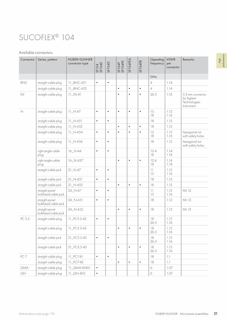
SUCOFLEX® 104
Available connectors
Connector Series, pattern HUBER+SUHNERconnector type
SF10
4SF
104
E
SF10
4D
SF10
4P
SF10
4PE
SF10
4PE
A
SF10
4PB
Operatingfrequency
VSWRperconnector
Remarks
GHz
BNC straight cable plug 11_BNC-451 • • 4 1.14
straight cable plug 11_BNC-452 • • • 4 1.14
DV straight cable plug 11_DV-41 • • • 26.5 1.16 3.5 mm connector for AgilentTechnologies Instrument
N straight cable plug 11_N-47 • • • • • 1518
1.121.16
straight cable plug 11_N-451 • • 18 1.12
straight cable plug 11_N-452 • • • 18 1.12
straight cable plug 11_N-454 • • • • • 1518
1.121.16
hexagonal nut with safety holes
straight cable plug 11_N-456 • • 18 1.12 hexagonal nut with safety holes
right angle cable plug
16_N-44 • • 12.418
1.141.18
right angle cable plug
16_N-457 • • • 12.418
1.141.18
straight cable jack 21_N-47 • • 1115
1.121.16
straight cable jack 21_N-451 • • 18 1.12
straight cable jack 21_N-452 • • • 18 1.12
straight panel bulkhead cable jack
24_N-47 • • 1115
1.121.16
ML 12
straight panel bulkhead cable jack
24_N-451 • • 18 1.12 ML 12
straight panel bulkhead cable jack
24_N-452 • • • 18 1.12 ML 12
PC 3.5 straight cable plug 11_PC3.5-42 • • 1826.5
1.121.16
straight cable plug 11_PC3.5-43 • • • 1826.5
1.121.16
straight cable jack 21_PC3.5-42 • • 1826.5
1.121.16
straight cable jack 21_PC3.5-43 • • • 1826.5
1.121.16
PC 7 straight cable plug 11_PC7-41 • • 18 1.1
straight cable plug 11_PC7-42 • • • 18 1.1
QMA straight cable plug 11_QMA-W401 • 6 1.07
QN straight cable plug 11_QN-403 • 6 1.07
HUBER+SUHNER Microwave assemblies32 HUBER+SUHNER Microwave assemblies32
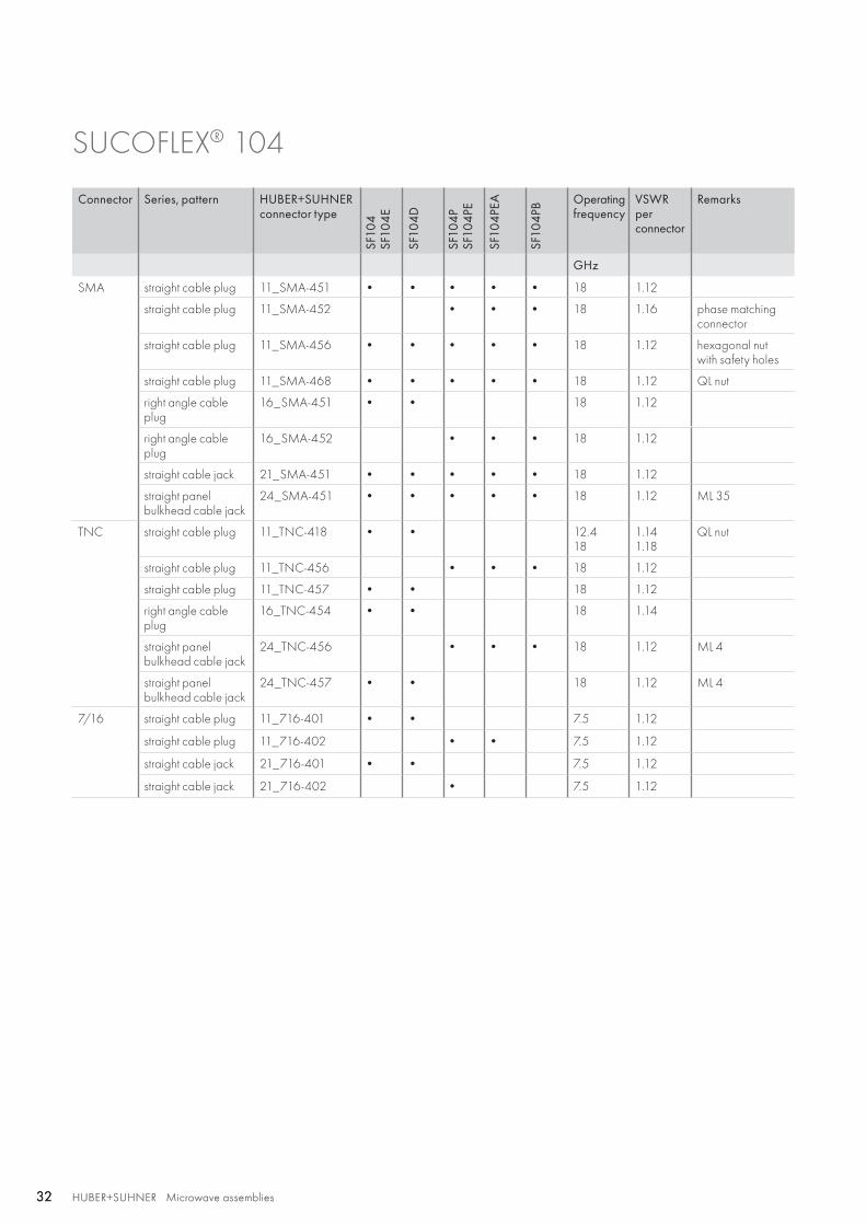
SUCOFLEX® 104
Connector Series, pattern HUBER+SUHNERconnector type
SF10
4SF
104
E
SF10
4D
SF10
4P
SF10
4PE
SF10
4PE
A
SF10
4PB
Operatingfrequency
VSWRperconnector
Remarks
GHz
SMA straight cable plug 11_SMA-451 • • • • • 18 1.12
straight cable plug 11_SMA-452 • • • 18 1.16 phase matching connector
straight cable plug 11_SMA-456 • • • • • 18 1.12 hexagonal nut with safety holes
straight cable plug 11_SMA-468 • • • • • 18 1.12 QL nut
right angle cable plug
16_SMA-451 • • 18 1.12
right angle cable plug
16_SMA-452 • • • 18 1.12
straight cable jack 21_SMA-451 • • • • • 18 1.12
straight panel bulkhead cable jack
24_SMA-451 • • • • • 18 1.12 ML 35
TNC straight cable plug 11_TNC-418 • • 12.418
1.141.18
QL nut
straight cable plug 11_TNC-456 • • • 18 1.12
straight cable plug 11_TNC-457 • • 18 1.12
right angle cable plug
16_TNC-454 • • 18 1.14
straight panel bulkhead cable jack
24_TNC-456 • • • 18 1.12 ML 4
straight panel bulkhead cable jack
24_TNC-457 • • 18 1.12 ML 4
7/16 straight cable plug 11_716-401 • • 7.5 1.12
straight cable plug 11_716-402 • • 7.5 1.12
straight cable jack 21_716-401 • • 7.5 1.12
straight cable jack 21_716-402 • 7.5 1.12
HUBER+SUHNER Microwave assembliesAbbreviations see page 176 33HUBER+SUHNER Microwave assemblies 33
Hig
h
perf
orm
ance
SUCOFLEX® 104
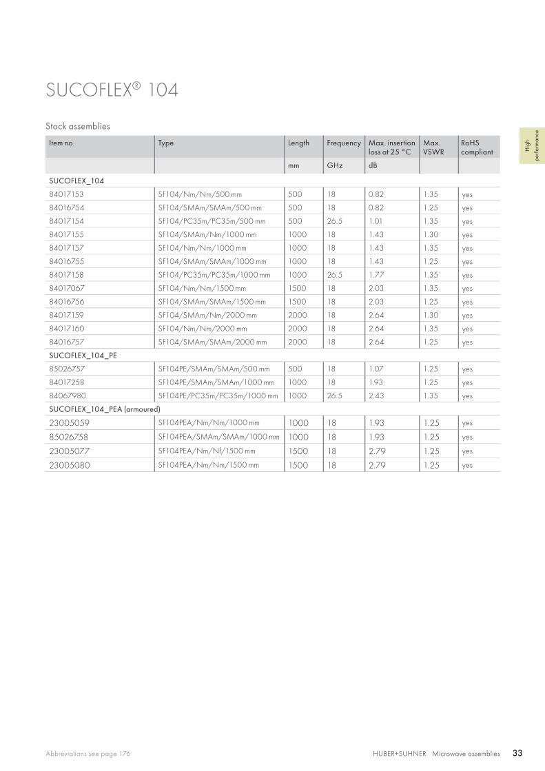
Stock assemblies
Item no. Type Length Frequency Max. insertion loss at 25 °C
Max.VSWR
RoHS compliant
mm GHz dB
SUCOFLEX_104
84017153 SF104/Nm/Nm/500 mm 500 18 0.82 1.35 yes
84016754 SF104/SMAm/SMAm/500 mm 500 18 0.82 1.25 yes
84017154 SF104/PC35m/PC35m/500 mm 500 26.5 1.01 1.35 yes
84017155 SF104/SMAm/Nm/1000 mm 1000 18 1.43 1.30 yes
84017157 SF104/Nm/Nm/1000 mm 1000 18 1.43 1.35 yes
84016755 SF104/SMAm/SMAm/1000 mm 1000 18 1.43 1.25 yes
84017158 SF104/PC35m/PC35m/1000 mm 1000 26.5 1.77 1.35 yes
84017067 SF104/Nm/Nm/1500 mm 1500 18 2.03 1.35 yes
84016756 SF104/SMAm/SMAm/1500 mm 1500 18 2.03 1.25 yes
84017159 SF104/SMAm/Nm/2000 mm 2000 18 2.64 1.30 yes
84017160 SF104/Nm/Nm/2000 mm 2000 18 2.64 1.35 yes
84016757 SF104/SMAm/SMAm/2000 mm 2000 18 2.64 1.25 yes
SUCOFLEX_104_PE
85026757 SF104PE/SMAm/SMAm/500 mm 500 18 1.07 1.25 yes
84017258 SF104PE/SMAm/SMAm/1000 mm 1000 18 1.93 1.25 yes
84067980 SF104PE/PC35m/PC35m/1000 mm 1000 26.5 2.43 1.35 yes
SUCOFLEX_104_PEA (armoured)
23005059 SF104PEA/Nm/Nm/1000 mm 1000 18 1.93 1.25 yes
85026758 SF104PEA/SMAm/SMAm/1000 mm 1000 18 1.93 1.25 yes
23005077 SF104PEA/Nm/Nf/1500 mm 1500 18 2.79 1.25 yes
23005080 SF104PEA/Nm/Nm/1500 mm 1500 18 2.79 1.25 yes
SF 106/106P/106I
SF 106A/106PA
SF 106D
HUBER+SUHNER Microwave assemblies34 HUBER+SUHNER Microwave assemblies34
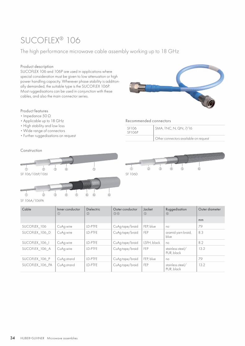
SUCOFLEX® 106 The high performance microwave cable assembly working up to 18 GHz
Product descriptionSUCOFLEX 106 and 106P are used in applications where special consideration must be given to low attenuation or high power handling capacity. Wherever phase stability is addition-ally demanded, the suitable type is the SUCOFLEX 106P. Most ruggedisations can be used in conjunction with these cables, and also the main connector series.
Product features• Impedance 50 Ω • Applicable up to 18 GHz• High stability and low loss• Wide range of connectors• Further ruggedisations on request
Recommended connectors
SF106SF106P
SMA, TNC, N, QN, 7/16
Other connectors available on request
Cable Inner conductor
Dielectric
Outer conductor
Jacket
Ruggedisation
Outer diameter
mm
SUCOFLEX_106 CuAg wire LD-PTFE CuAg tape/braid FEP, blue no 7.9
SUCOFLEX_106_D CuAg wire LD-PTFE CuAg tape/braid FEP aramid yarn braid, blue
8.3
SUCOFLEX_106_I CuAg wire LD-PTFE CuAg tape/braid LSFH, black no 8.2
SUCOFLEX_106_A CuAg wire LD-PTFE CuAg tape/braid FEP stainless steel/PUR, black
13.2
SUCOFLEX_106_P CuAg strand LD-PTFE CuAg tape/braid FEP, blue no 7.9
SUCOFLEX_106_PA CuAg strand LD-PTFE CuAg tape/braid FEP stainless steel/PUR, black
13.2
Construction
HUBER+SUHNER Microwave assembliesAbbreviations see page 176 35HUBER+SUHNER Microwave assemblies 35
Hig
h
perf
orm
ance
SUCOFLEX® 106
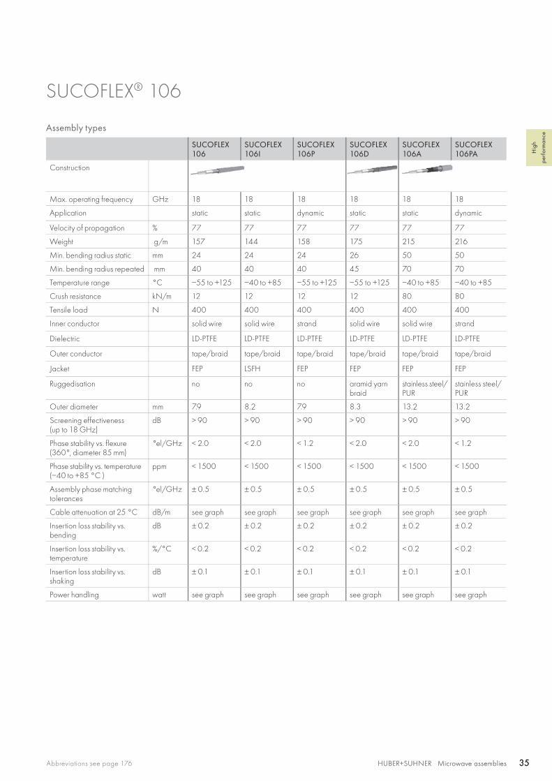
Assembly types
SUCOFLEX 106
SUCOFLEX 106I
SUCOFLEX 106P
SUCOFLEX 106D
SUCOFLEX 106A
SUCOFLEX 106PA
Construction
Max. operating frequency GHz 18 18 18 18 18 18
Application static static dynamic static static dynamic
Velocity of propagation % 77 77 77 77 77 77
Weight g/m 157 144 158 175 215 216
Min. bending radius static mm 24 24 24 26 50 50
Min. bending radius repeated mm 40 40 40 45 70 70
Temperature range °C −55 to +125 −40 to +85 −55 to +125 −55 to +125 −40 to +85 −40 to +85
Crush resistance kN/m 12 12 12 12 80 80
Tensile load N 400 400 400 400 400 400
Inner conductor solid wire solid wire strand solid wire solid wire strand
Dielectric LD-PTFE LD-PTFE LD-PTFE LD-PTFE LD-PTFE LD-PTFE
Outer conductor tape/braid tape/braid tape/braid tape/braid tape/braid tape/braid
Jacket FEP LSFH FEP FEP FEP FEP
Ruggedisation no no no aramid yarn braid
stainless steel/PUR
stainless steel/PUR
Outer diameter mm 7.9 8.2 7.9 8.3 13.2 13.2
Screening effectiveness(up to 18 GHz)
dB > 90 > 90 > 90 > 90 > 90 > 90
Phase stability vs. flexure (360°, diameter 85 mm)
°el/GHz < 2.0 < 2.0 < 1.2 < 2.0 < 2.0 < 1.2
Phase stability vs. temperature (−40 to +85 °C )
ppm < 1500 < 1500 < 1500 < 1500 < 1500 < 1500
Assembly phase matching tolerances
°el/GHz ± 0.5 ± 0.5 ± 0.5 ± 0.5 ± 0.5 ± 0.5
Cable attenuation at 25 °C dB/m see graph see graph see graph see graph see graph see graph
Insertion loss stability vs. bending
dB ± 0.2 ± 0.2 ± 0.2 ± 0.2 ± 0.2 ± 0.2
Insertion loss stability vs. temperature
%/°C < 0.2 < 0.2 < 0.2 < 0.2 < 0.2 < 0.2
Insertion loss stability vs. shaking
dB ± 0.1 ± 0.1 ± 0.1 ± 0.1 ± 0.1 ± 0.1
Power handling watt see graph see graph see graph see graph see graph see graph
0 1 2 3 4 5 6 7 8 9 10 11 12 13 14 15 16 17 18
0 1 2 3 4 5 6 7 8 9 10 11 12 13 14 15 16 17 18
0.8
0.6
1.2
0.2
0.4
0
200
400
600
800
1000
1200
1400
1600
1800
2000
0
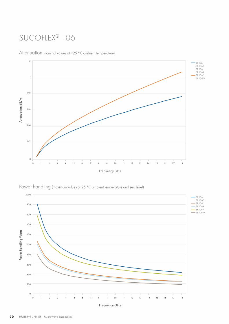
SF 106SF 106DSF 106ISF 106ASF 106PSF 106PA
SF 106SF 106DSF 106ISF 106ASF 106PSF 106PA
1
HUBER+SUHNER Microwave assemblies36 HUBER+SUHNER Microwave assemblies36
SUCOFLEX® 106
Attenuation (nominal values at +25 °C ambient temperature)
Power handling (maximum values at 25 °C ambient temperature and sea level)
Atte
nuat
ion
dB/m
Pow
er h
andl
ing
Wat
ts
Frequency GHz
Frequency GHz
HUBER+SUHNER Microwave assembliesAbbreviations see page 176 37HUBER+SUHNER Microwave assemblies 37
Hig
h
perf
orm
ance
SUCOFLEX® 106
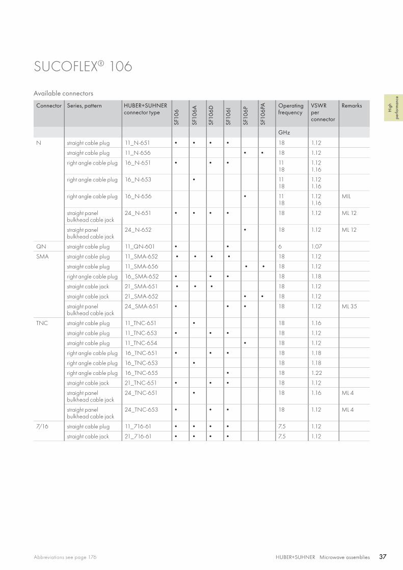
Available connectors
Connector Series, pattern HUBER+SUHNERconnector type
SF10
6
SF10
6A
SF10
6D
SF10
6I
SF10
6P
SF10
6PA Operating
frequencyVSWRperconnector
Remarks
GHz
N straight cable plug 11_N-651 • • • • 18 1.12
straight cable plug 11_N-656 • • 18 1.12
right angle cable plug 16_N-651 • • • 1118
1.121.16
right angle cable plug 16_N-653 • 1118
1.121.16
right angle cable plug 16_N-656 • 1118
1.121.16
MIL
straight panel bulkhead cable jack
24_N-651 • • • • 18 1.12 ML 12
straight panel bulkhead cable jack
24_N-652 • 18 1.12 ML 12
QN straight cable plug 11_QN-601 • • 6 1.07
SMA straight cable plug 11_SMA-652 • • • • 18 1.12
straight cable plug 11_SMA-656 • • 18 1.12
right angle cable plug 16_SMA-652 • • • 18 1.18
straight cable jack 21_SMA-651 • • • 18 1.12
straight cable jack 21_SMA-652 • • 18 1.12
straight panel bulkhead cable jack
24_SMA-651 • • • 18 1.12 ML 35
TNC straight cable plug 11_TNC-651 • 18 1.16
straight cable plug 11_TNC-653 • • • 18 1.12
straight cable plug 11_TNC-654 • 18 1.12
right angle cable plug 16_TNC-651 • • • 18 1.18
right angle cable plug 16_TNC-653 • 18 1.18
right angle cable plug 16_TNC-655 • 18 1.22
straight cable jack 21_TNC-651 • • • 18 1.12
straight panel bulkhead cable jack
24_TNC-651 • 18 1.16 ML 4
straight panel bulkhead cable jack
24_TNC-653 • • • 18 1.12 ML 4
7/16 straight cable plug 11_716-61 • • • • 7.5 1.12
straight cable jack 21_716-61 • • • • 7.5 1.12
HUBER+SUHNER Microwave assemblies38 HUBER+SUHNER Microwave assemblies38
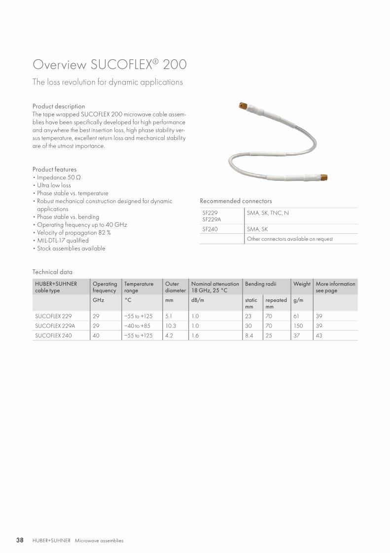
Overview SUCOFLEX® 200 The loss revolution for dynamic applications
Product descriptionThe tape wrapped SUCOFLEX 200 microwave cable assem-blies have been specifically developed for high performance and anywhere the best insertion loss, high phase stability ver-sus temperature, excellent return loss and mechanical stability are of the utmost importance.
Product features• Impedance 50 Ω • Ultra low loss• Phase stable vs. temperature• Robust mechanical construction designed for dynamic
applications• Phase stable vs. bending • Operating frequency up to 40 GHz• Velocity of propagation 82 %• MIL-DTL-17 qualified• Stock assemblies available
Recommended connectors
SF229SF229A
SMA, SK, TNC, N
SF240 SMA, SK
Other connectors available on request
Technical data
HUBER+SUHNER cable type
Operating frequency
Temperature range
Outerdiameter
Nominal attenuation 18 GHz, 25 °C
Bending radii Weight More information see page
GHz °C mm dB/m staticmm
repeatedmm
g/m
SUCOFLEX 229 29 −55 to +125 5.1 1.0 23 70 61 39
SUCOFLEX 229A 29 −40 to +85 10.3 1.0 30 70 150 39
SUCOFLEX 240 40 −55 to +125 4.2 1.6 8.4 25 37 43
SF 229ASF 229
HUBER+SUHNER Microwave assembliesAbbreviations see page 176 39HUBER+SUHNER Microwave assemblies 39
Hig
h
perf
orm
ance
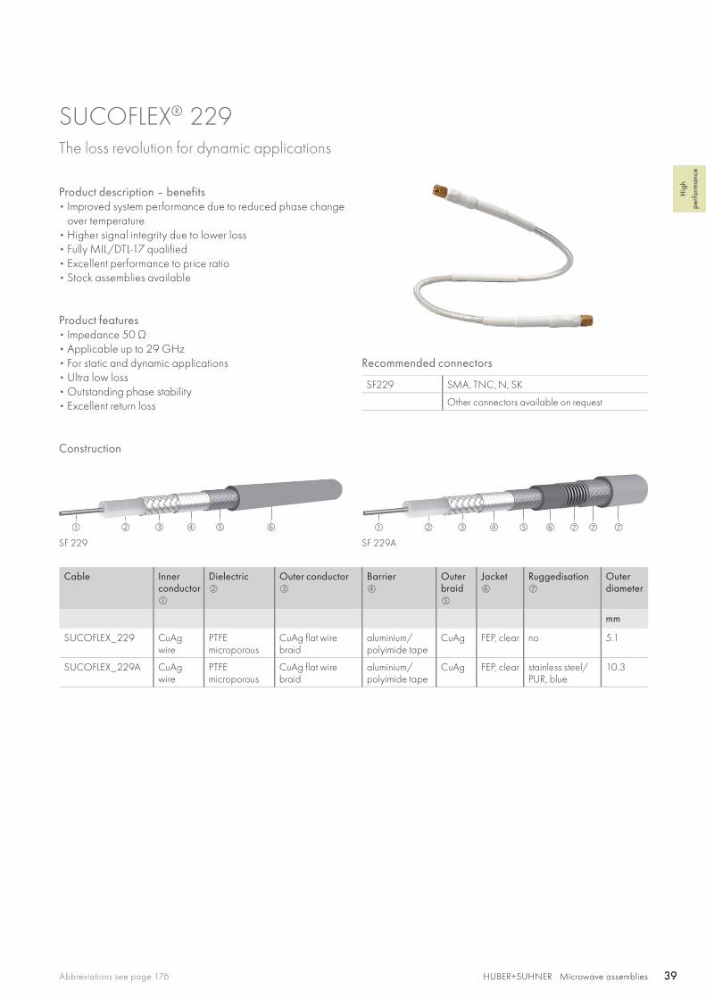
SUCOFLEX® 229 The loss revolution for dynamic applications
Product description – benefits• Improved system performance due to reduced phase change
over temperature• Higher signal integrity due to lower loss• Fully MIL/DTL-17 qualified• Excellent performance to price ratio• Stock assemblies available
Product features• Impedance 50 Ω • Applicable up to 29 GHz• For static and dynamic applications • Ultra low loss• Outstanding phase stability• Excellent return loss
Recommended connectors
SF229 SMA, TNC, N, SK
Other connectors available on request
Cable Inner conductor
Dielectric
Outer conductor
Barrier
Outer braid
Jacket
Ruggedisation
Outerdiameter
mm
SUCOFLEX_229 CuAg wire
PTFEmicroporous
CuAg flat wire braid
aluminium/polyimide tape
CuAg FEP, clear no 5.1
SUCOFLEX_229A CuAg wire
PTFEmicroporous
CuAg flat wire braid
aluminium/polyimide tape
CuAg FEP, clear stainless steel/PUR, blue
10.3
Construction

HUBER+SUHNER Microwave assemblies40 HUBER+SUHNER Microwave assemblies40
Assembly types
SUCOFLEX_229 SUCOFLEX_229A
Construction
Max. operating frequency GHz 29 29
Application static and dynamic static and dynamic
Velocity of propagation % 82 82
Weight g/m 61 150
Min. bending radius static mm 23 30
Min. bending radius repeated mm 70 70
Temperature range °C −55 to +125(−65 to +200 °C on request)
−40 to +85
Tensile load N 133 133
Inner conductor solid wire solid wire
Dielectric PTFE microporous PTFE microporous
Outer conductor flat wire braid flat wire braid
Barrier tape/braid tape/braid
Jacket FEP FEP
Ruggedisation no stainless steel/PUR
Outer diameter mm 5.1 10.3
Screening effectiveness(up to 18 GHz)
dB > 90 > 90
Phase stability vs. flexure(360°, diameter 55 mm)
°el/GHz < 0.65 < 0.65
Phase stability vs. temperature (−40 to +85 °C )
ppm < 800 < 800
Assembly phase matching tolerances °el/GHz ± 0.5 ± 0.5
Cable attenuation at 25 °C dB/m see graph see graph
Insertion loss stability vs. bending dB ± 0.2 ± 0.2
Insertion loss stability vs. temperature %/°C < 0.21 < 0.21
Insertion loss stability vs. shaking dB ± 0.1 ± 0.1
Power handling watt see graph see graph
SUCOFLEX 229
1
1.2
1.4
1.6
0.2
0.4
0.6
0.8
0
SF 229SF 229A
SF 229SF 229A
200
400
600
800
1000
1200
1400
0
0 1 2 3 4 5 6 7 8 9 10 11 12 13 14 15 16 17 18 19 20 21 22 23 24 25 26 27 28 29
0 1 2 3 4 5 6 7 8 9 10 11 12 13 14 15 16 17 18 19 20 21 22 23 24 25 26 27 28 29
HUBER+SUHNER Microwave assembliesAbbreviations see page 176 41HUBER+SUHNER Microwave assemblies 41
Gen
eral
info
rmat
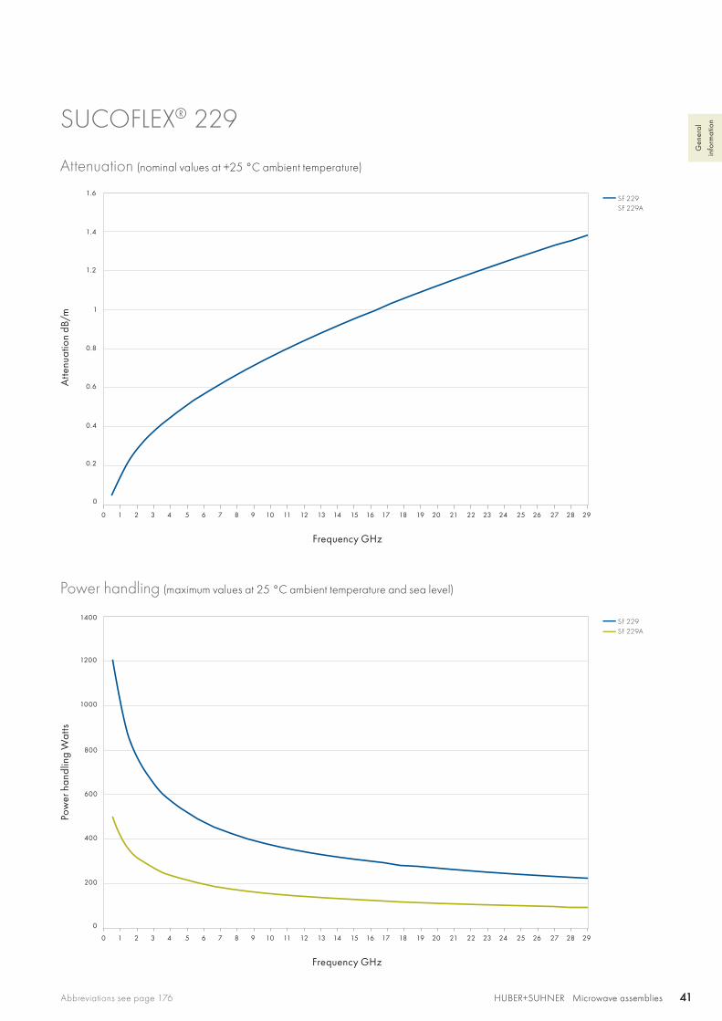
ionSUCOFLEX® 229
Attenuation (nominal values at +25 °C ambient temperature)
Power handling (maximum values at 25 °C ambient temperature and sea level)
Atte
nuat
ion
dB/m
Pow
er h
andl
ing
Wat
ts
Frequency GHz
Frequency GHz
HUBER+SUHNER Microwave assemblies42 HUBER+SUHNER Microwave assemblies42
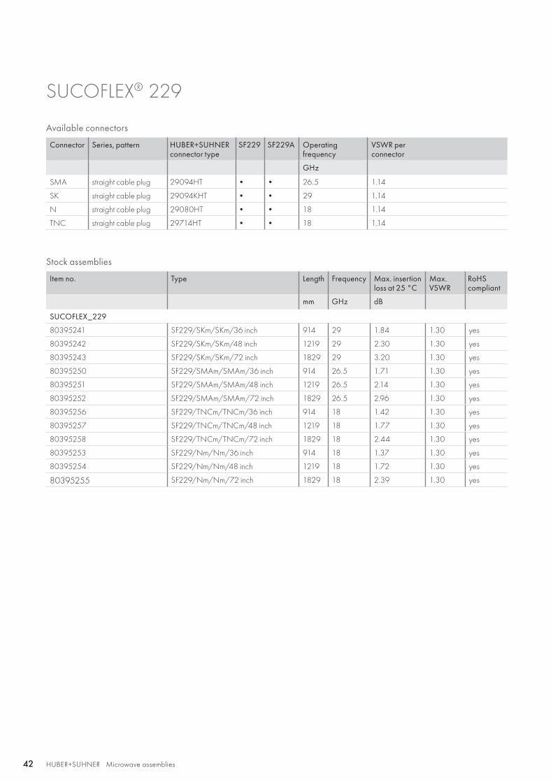
SUCOFLEX® 229
Stock assemblies
Item no. Type Length Frequency Max. insertion loss at 25 °C
Max.VSWR
RoHScompliant
mm GHz dB
SUCOFLEX_229
80395241 SF229/SKm/SKm/36 inch 914 29 1.84 1.30 yes
80395242 SF229/SKm/SKm/48 inch 1219 29 2.30 1.30 yes
80395243 SF229/SKm/SKm/72 inch 1829 29 3.20 1.30 yes
80395250 SF229/SMAm/SMAm/36 inch 914 26.5 1.71 1.30 yes
80395251 SF229/SMAm/SMAm/48 inch 1219 26.5 2.14 1.30 yes
80395252 SF229/SMAm/SMAm/72 inch 1829 26.5 2.96 1.30 yes
80395256 SF229/TNCm/TNCm/36 inch 914 18 1.42 1.30 yes
80395257 SF229/TNCm/TNCm/48 inch 1219 18 1.77 1.30 yes
80395258 SF229/TNCm/TNCm/72 inch 1829 18 2.44 1.30 yes
80395253 SF229/Nm/Nm/36 inch 914 18 1.37 1.30 yes
80395254 SF229/Nm/Nm/48 inch 1219 18 1.72 1.30 yes
80395255 SF229/Nm/Nm/72 inch 1829 18 2.39 1.30 yes
Available connectors
Connector Series, pattern HUBER+SUHNER connector type
SF229 SF229A Operatingfrequency
VSWR perconnector
GHz
SMA straight cable plug 29094HT • • 26.5 1.14
SK straight cable plug 29094KHT • • 29 1.14
N straight cable plug 29080HT • • 18 1.14
TNC straight cable plug 29714HT • • 18 1.14
HUBER+SUHNER Microwave assembliesAbbreviations see page 176 43HUBER+SUHNER Microwave assemblies 43
Hig
h
perf
orm
ance
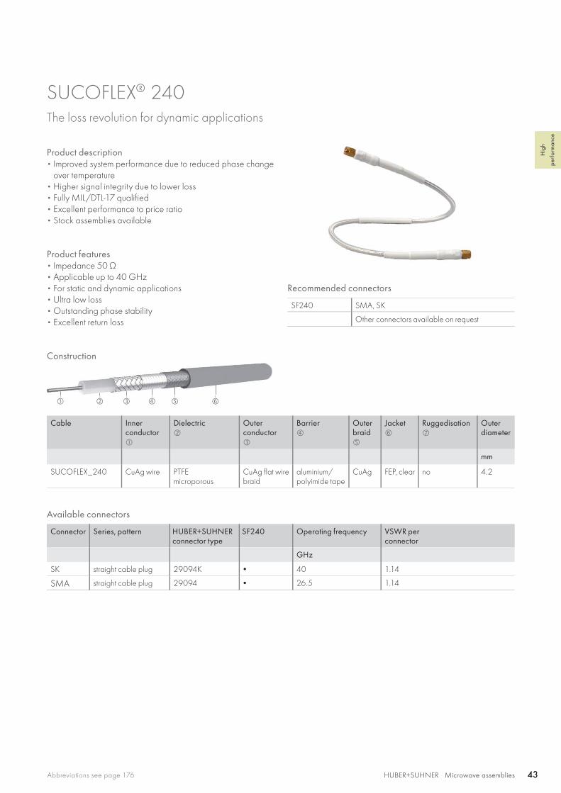
SUCOFLEX® 240 The loss revolution for dynamic applications
Product description• Improved system performance due to reduced phase change
over temperature• Higher signal integrity due to lower loss• Fully MIL/DTL-17 qualified• Excellent performance to price ratio• Stock assemblies available
Product features• Impedance 50 Ω• Applicable up to 40 GHz• For static and dynamic applications • Ultra low loss• Outstanding phase stability• Excellent return loss
Recommended connectors
SF240 SMA, SK
Other connectors available on request
Cable Innerconductor
Dielectric
Outerconductor
Barrier
Outer braid
Jacket
Ruggedisation
Outerdiameter
mm
SUCOFLEX_240 CuAg wire PTFEmicroporous
CuAg flat wire braid
aluminium/polyimide tape
CuAg FEP, clear no 4.2
Construction
Available connectors
Connector Series, pattern HUBER+SUHNER connector type
SF240 Operating frequency VSWR perconnector
GHz
SK straight cable plug 29094K • 40 1.14
SMA straight cable plug 29094 • 26.5 1.14
HUBER+SUHNER Microwave assemblies44 HUBER+SUHNER Microwave assemblies44
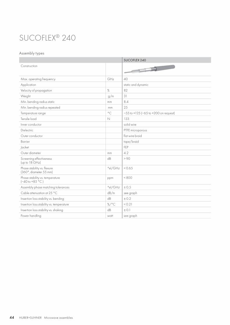
Assembly types
SUCOFLEX 240
Construction
Max. operating frequency GHz 40
Application static and dynamic
Velocity of propagation % 82
Weight g/m 31
Min. bending radius static mm 8.4
Min. bending radius repeated mm 25
Temperature range °C −55 to +125 (−65 to +200 on request)
Tensile load N 133
Inner conductor solid wire
Dielectric PTFE microporous
Outer conductor flat wire braid
Barrier tape/braid
Jacket FEP
Outer diameter mm 4.2
Screening effectiveness(up to 18 GHz)
dB > 90
Phase stability vs. flexure(360°, diameter 55 mm)
°el/GHz < 0.65
Phase stability vs. temperature (−40 to +85 °C )
ppm < 800
Assembly phase matching tolerances °el/GHz ± 0.5
Cable attenuation at 25 °C dB/m see graph
Insertion loss stability vs. bending dB ± 0.2
Insertion loss stability vs. temperature %/°C < 0.21
Insertion loss stability vs. shaking dB ± 0.1
Power handling watt see graph
SUCOFLEX® 240

0 2 4 6 8 10 12 14 16 18 20 22 24 26 28 30 32 34 36 38 40
0 2 4 6 8 10 12 14 16 18 20 22 24 26 28 30 32 34 36 38 40
2.5
1.5
0.5
200
300
400
500
600
700
800
900
1000
100
0
SF 240
SF 240
3
2
1
0
HUBER+SUHNER Microwave assembliesAbbreviations see page 176 45HUBER+SUHNER Microwave assemblies 45
Hig
h
perf
orm
ance
SUCOFLEX® 240
Attenuation (nominal values at +25 °C ambient temperature)
Power handling (maximum values at 25 °C ambient temperature and sea level)
Atte
nuat
ion
dB/m
Pow
er h
andl
ing
Wat
ts
Frequency GHz
Frequency GHz

HUBER+SUHNER Microwave assemblies46 HUBER+SUHNER Microwave assemblies46
Overview SUCOFLEX® 300The light weight, high performance cable assembly
Product descriptionThe SUCOFLEX 300 lightweight, low-loss flexible microwave cable assemblies are high-end products designed to meet the stringent needs of space flight systems (e. g. satellites) and aerospace systems (aircraft, helicopters, missiles), which are subjected to extremely severe operating conditions.The 300 series offers a consistently outstanding mechanical and electrical performance, stability and reliability up to 40 GHz. The added feature of this SUCOFLEX type is a weight reduc-tion of up to 50 % compared to our conventional products.
Product features for space applications• Assemblies produced in a clean environment room• Specifically designed lightweight connectors• Extensive testing of assemblies• High-end assemblies approved by Europe's leading satellite
manufacturers
Product features for defense applications• Lightweight reduces overall system weight and aids portability• Rugged connectors made for easy serviceability• Specialised range of connectors, which is being continuously
extended• Comprehensive tested product range• High-end product approved for most sophisticated military
aircraft• Additional D-armour provide increased crush and abrasion
resistance
Recommended connectors
SF301SF301_Space
SMA
SF302 SMA, SK, PC2.4
SF304SF304_Space
SMA, N, TNC
SF307_Space TNC
SF329 SMA, SK, TNC, N
SF340 SMA, SK
Other connectors available on request
Technical data
HUBER+SUHNERcable type
Operating frequency
Temperature range
Outer diameter
Nominal attenuation 18 GHz, 25 °C
Bending radii Weight More information see page
GHz °C mm dB/m staticmm
repeated mm
g
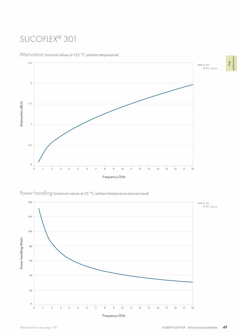
SUCOFLEX 301 18 −55 to +125 3.5 2.0 15 20 23.9 47
SUCOFLEX 301_Space 18 −55 to +150 3.5 2.0 15 20 23.9 47
SUCOFLEX 302 40 −55 to +125 3.7 1.9 15 30 29.0 50
SUCOFLEX 304 18 −55 to +125 5.4 1.2 20 50 46.0 54
SUCOFLEX 304_Space 18 −55 to +150 5.4 1.2 20 50 46.0 54
SUCOFLEX 307_Space 8 −55 to +150 9.0 0.4 at 8 GHz 50 100 133 57
SUCOFLEX 329 29 −65 to +165 5.1 1.0 23 70 42 60
SUCOFLEX 340 40 −65 to +165 4.2 1.6 8.4 25 18 63

HUBER+SUHNER Microwave assembliesAbbreviations see page 176 47HUBER+SUHNER Microwave assemblies 47
Hig
h
perf
orm
ance
SUCOFLEX® 301 The light weight, high performance microwave cable assembly working up to 18 GHz
Product descriptionThe SUCOFLEX 301 light weight, high end cable assemblies are designed to provide optimal performance up to 18 GHz were light weight, stringent electrical requirements – in particu-lar stability and low loss, are important.
Product features• Impedance 50 Ω • Applicable up to 18 GHz• Up to 40 % weight reduction compared to standard
SUCOFLEX 101 assemblies (lower launching costs)• Production in clean room• All space connectors vented• Outgassing according ECSS-Q-ST-70-02C and
NASA reference publication 1124• MIL-DTL-17 qualified• Low loss
Recommended connectors
SF301SF301_Space
SMA
Other connectors available on request
Cable Inner conductor
Dielectric
Outer conductor
Jacket
Outer diameter
mm
SUCOFLEX_301 AlCuAg wire LD-PTFE CuAg tape/AlCuAg braid ETFE, blue 3.5
SUCOFLEX_301_Space AlCuAg wire LD-PTFE CuAg tape/AlCuAg braid ETFE, blue 3.5
Other SUCOFLEX 301 cables available on request.
Construction
Available connectors
Connector Series, pattern HUBER+SUHNERconnector type
SF30
1
SF30
1_Sp
ace Op.
freq.VSWRper connector
Remarks
GHz
SMA straight cable plug 11_SMA-153 • 18 1.12
straight cable plug 11_SMA-187_Space • 1218
1.071.12
vented
right angle cable plug 16_SMA-189_Space • 1218
1.071.12
vented
HUBER+SUHNER Microwave assemblies48 HUBER+SUHNER Microwave assemblies48
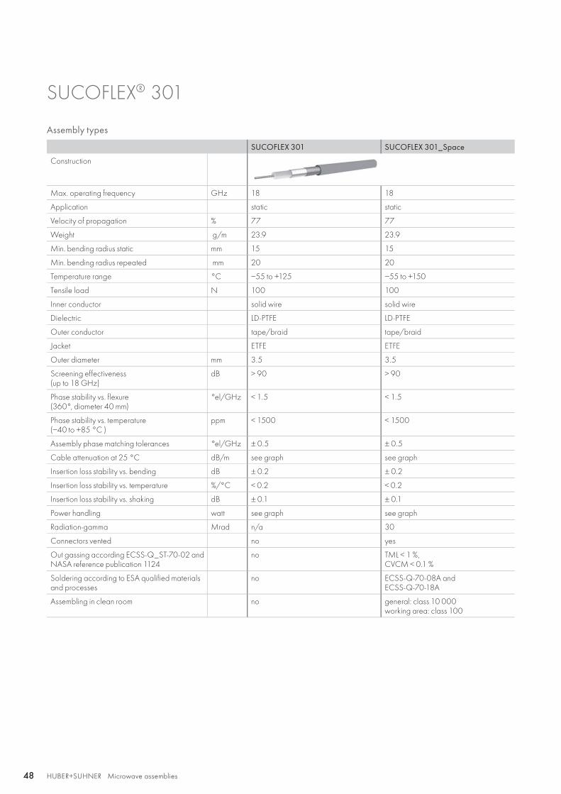
SUCOFLEX® 301
Assembly types
SUCOFLEX 301 SUCOFLEX 301_Space
Construction
Max. operating frequency GHz 18 18
Application static static
Velocity of propagation % 77 77
Weight g/m 23.9 23.9
Min. bending radius static mm 15 15
Min. bending radius repeated mm 20 20
Temperature range °C −55 to +125 −55 to +150
Tensile load N 100 100
Inner conductor solid wire solid wire
Dielectric LD-PTFE LD-PTFE
Outer conductor tape/braid tape/braid
Jacket ETFE ETFE
Outer diameter mm 3.5 3.5
Screening effectiveness(up to 18 GHz)
dB > 90 > 90
Phase stability vs. flexure(360°, diameter 40 mm)
°el/GHz < 1.5 < 1.5
Phase stability vs. temperature (−40 to +85 °C )
ppm < 1500 < 1500
Assembly phase matching tolerances °el/GHz ± 0.5 ± 0.5
Cable attenuation at 25 °C dB/m see graph see graph
Insertion loss stability vs. bending dB ± 0.2 ± 0.2
Insertion loss stability vs. temperature %/°C < 0.2 < 0.2
Insertion loss stability vs. shaking dB ± 0.1 ± 0.1
Power handling watt see graph see graph
Radiation-gamma Mrad n/a 30
Connectors vented no yes
Out gassing according ECSS-Q_ST-70-02 and NASA reference publication 1124
no TML < 1 %, CVCM < 0.1 %
Soldering according to ESA qualified materials and processes
no ECSS-Q-70-08A andECSS-Q-70-18A
Assembling in clean room no general: class 10 000working area: class 100
0 1 2 3 4 5 6 7 8 9 10 11 12 13 14 15 16 17 18
0 1 2 3 4 5 6 7 8 9 10 11 12 13 14 15 16 17 18
1
2
2.5
1.5
20
40
60
80
100
120
140
0.5
0
0
SF 301SF 301_Space
SF 301SF 301_Space
HUBER+SUHNER Microwave assembliesAbbreviations see page 176 49HUBER+SUHNER Microwave assemblies 49
Hig
h
perf
orm
ance
SUCOFLEX® 301
Attenuation (nominal values at +25 °C ambient temperature)
Power handling (maximum values at 25 °C ambient temperature and sea level)
Atte
nuat
ion
dB/m
Pow
er h
andl
ing
Wat
ts
Frequency GHz
Frequency GHz
SF 302 SF 302_D
HUBER+SUHNER Microwave assemblies50 HUBER+SUHNER Microwave assemblies50
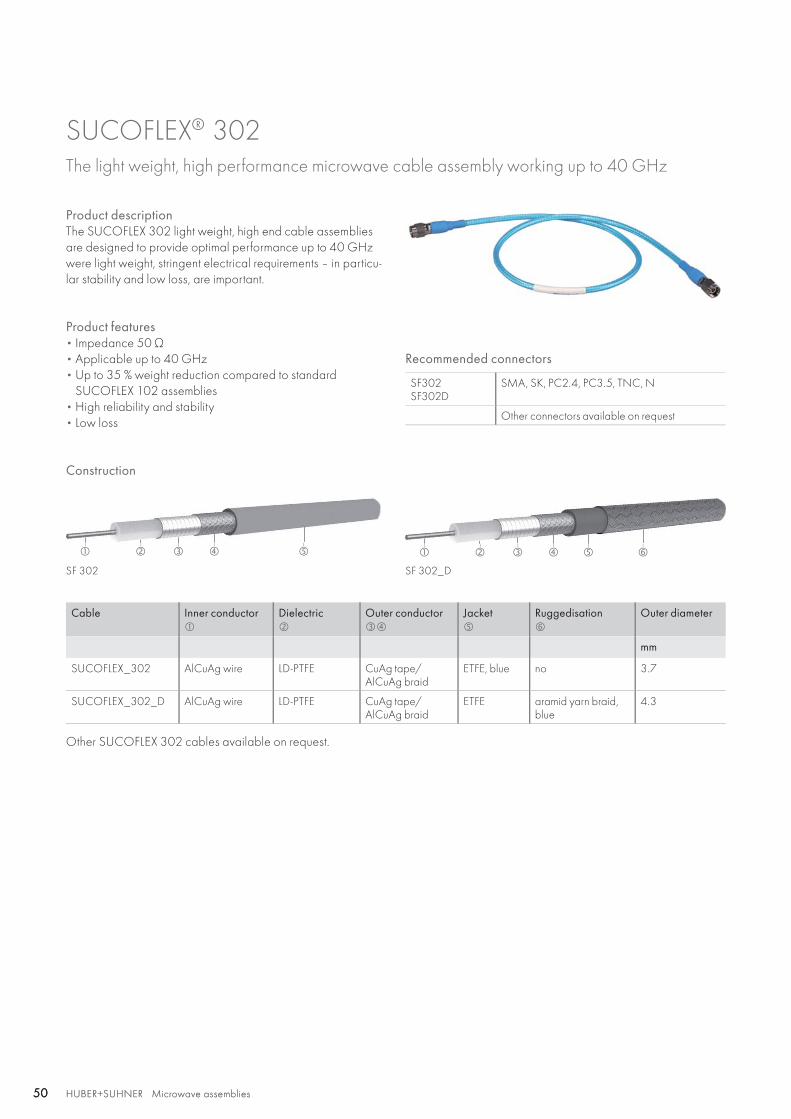
SUCOFLEX® 302 The light weight, high performance microwave cable assembly working up to 40 GHz
Product descriptionThe SUCOFLEX 302 light weight, high end cable assemblies are designed to provide optimal performance up to 40 GHz were light weight, stringent electrical requirements – in particu-lar stability and low loss, are important.
Product features• Impedance 50 Ω • Applicable up to 40 GHz• Up to 35 % weight reduction compared to standard
SUCOFLEX 102 assemblies • High reliability and stability• Low loss
Recommended connectors
SF302SF302D
SMA, SK, PC2.4, PC3.5, TNC, N
Other connectors available on request
Construction
Cable Inner conductor
Dielectric
Outer conductor
Jacket
Ruggedisation
Outer diameter
mm
SUCOFLEX_302 AlCuAg wire LD-PTFE CuAg tape/ AlCuAg braid
ETFE, blue no 3.7
SUCOFLEX_302_D AlCuAg wire LD-PTFE CuAg tape/ AlCuAg braid
ETFE aramid yarn braid,blue
4.3
Other SUCOFLEX 302 cables available on request.

HUBER+SUHNER Microwave assembliesAbbreviations see page 176 51HUBER+SUHNER Microwave assemblies 51
Hig
h
perf
orm
ance
SUCOFLEX® 302
Assembly types
SUCOFLEX 302 SUCOFLEX 302D
Construction
Max. operating frequency GHz 40 40
Application static static
Velocity of propagation % 77 77
Weight g/m 29 31
Min. bending radius static mm 15 15
Min. bending radius repeated mm 30 30
Temperature range °C −55 to +125 −55 to +125
Tensile load N 150 150
Inner conductor solid wire solid wire
Dielectric LD-PTFE LD-PTFE
Outer conductor tape/braid tape/braid
Jacket ETFE ETFE
Ruggedisation no aramid yarn braid
Outer diameter mm 3.7 4.3
Screening effectiveness(up to 18 GHz)
dB > 90 > 90
Phase stability vs. flexure(360°, diameter 40 mm)
°el/GHz < 1.5 < 1.5
Phase stability vs. temperature (−40 to +85 °C )
ppm < 1500 < 1500
Assembly phase matching tolerances °el/GHz ± 0.5 ± 0.5
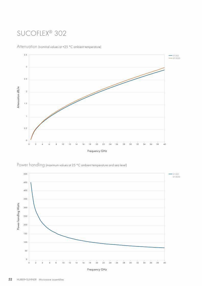
Cable attenuation at 25 °C dB/m see graph see graph
Insertion loss stability vs. bending dB ± 0.2 ± 0.2
Insertion loss stability vs. temperature %/°C < 0.2 < 0.2
Insertion loss stability vs. shaking dB ± 0.1 ± 0.1
Power handling watt see graph see graph
Connectors vented no no
Assembling in clean room no no
2.5
3.5
1.5
0.5
3
2
1
0
SF 302SF 302D
SF 302SF 302D
150
200
250
300
350
400
450
500
100
50
0
0 2 4 6 8 10 12 14 16 18 20 22 24 26 28 30 32 34 36 38 40
0 2 4 6 8 10 12 14 16 18 20 22 24 26 28 30 32 34 36 38 40
HUBER+SUHNER Microwave assemblies52 HUBER+SUHNER Microwave assemblies52
SUCOFLEX® 302
Attenuation (nominal values at +25 °C ambient temperature)
Power handling (maximum values at 25 °C ambient temperature and sea level)
Atte
nuat
ion
dB/m
Pow
er h
andl
ing
Wat
ts
Frequency GHz
Frequency GHz
HUBER+SUHNER Microwave assembliesAbbreviations see page 176 53HUBER+SUHNER Microwave assemblies 53
Hig
h
perf
orm
ance
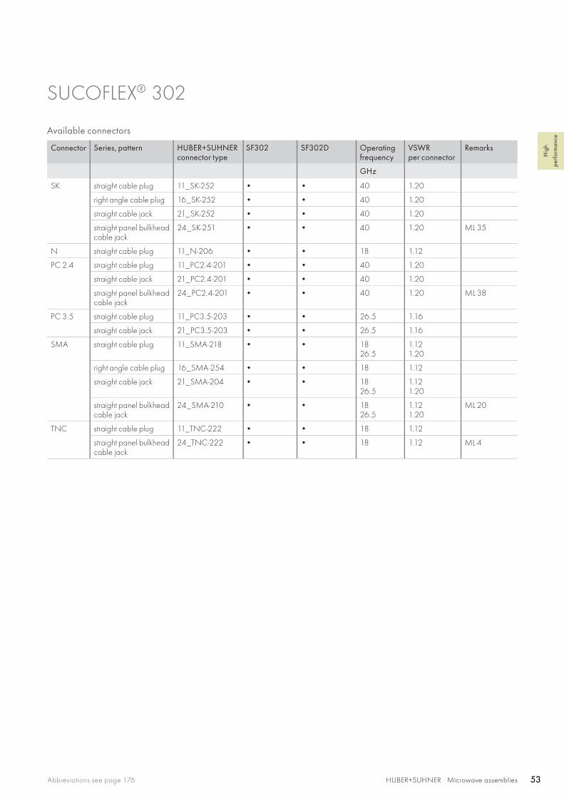
SUCOFLEX® 302
Available connectors
Connector Series, pattern HUBER+SUHNERconnector type
SF302 SF302D Operatingfrequency
VSWRper connector
Remarks
GHz
SK straight cable plug 11_SK-252 • • 40 1.20
right angle cable plug 16_SK-252 • • 40 1.20
straight cable jack 21_SK-252 • • 40 1.20
straight panel bulkhead cable jack
24_SK-251 • • 40 1.20 ML 35
N straight cable plug 11_N-206 • • 18 1.12
PC 2.4 straight cable plug 11_PC2.4-201 • • 40 1.20
straight cable jack 21_PC2.4-201 • • 40 1.20
straight panel bulkhead cable jack
24_PC2.4-201 • • 40 1.20 ML 38
PC 3.5 straight cable plug 11_PC3.5-203 • • 26.5 1.16
straight cable jack 21_PC3.5-203 • • 26.5 1.16
SMA straight cable plug 11_SMA-218 • • 1826.5
1.121.20
right angle cable plug 16_SMA-254 • • 18 1.12
straight cable jack 21_SMA-204 • • 1826.5
1.121.20
straight panel bulkhead cable jack
24_SMA-210 • • 1826.5
1.121.20
ML 20
TNC straight cable plug 11_TNC-222 • • 18 1.12
straight panel bulkhead cable jack
24_TNC-222 • • 18 1.12 ML 4
SF 304/SF 304_Space SF 304_D
HUBER+SUHNER Microwave assemblies54 HUBER+SUHNER Microwave assemblies54
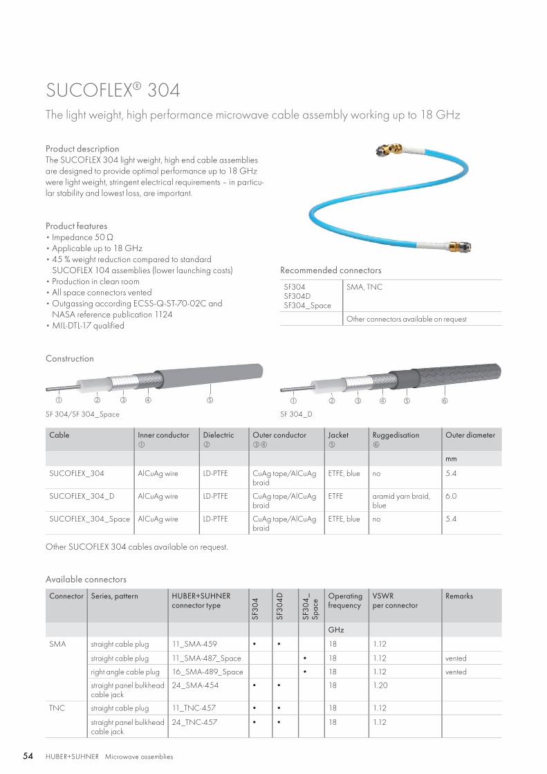
SUCOFLEX® 304 The light weight, high performance microwave cable assembly working up to 18 GHz
Product descriptionThe SUCOFLEX 304 light weight, high end cable assemblies are designed to provide optimal performance up to 18 GHz were light weight, stringent electrical requirements – in particu-lar stability and lowest loss, are important.
Product features• Impedance 50 Ω • Applicable up to 18 GHz• 45 % weight reduction compared to standard
SUCOFLEX 104 assemblies (lower launching costs)• Production in clean room• All space connectors vented• Outgassing according ECSS-Q-ST-70-02C and
NASA reference publication 1124• MIL-DTL-17 qualified
Recommended connectors
SF304 SF304D SF304_Space
SMA, TNC
Other connectors available on request
Construction
Cable Inner conductor
Dielectric
Outer conductor
Jacket
Ruggedisation
Outer diameter
mm
SUCOFLEX_304 AlCuAg wire LD-PTFE CuAg tape/AlCuAg braid
ETFE, blue no 5.4
SUCOFLEX_304_D AlCuAg wire LD-PTFE CuAg tape/AlCuAg braid
ETFE aramid yarn braid,blue
6.0
SUCOFLEX_304_Space AlCuAg wire LD-PTFE CuAg tape/AlCuAg braid
ETFE, blue no 5.4
Other SUCOFLEX 304 cables available on request.
Available connectors
Connector Series, pattern HUBER+SUHNERconnector type
SF30
4
SF30
4D
SF30
4_
Spac
e Operatingfrequency
VSWRper connector
Remarks
GHz
SMA straight cable plug 11_SMA-459 • • 18 1.12
straight cable plug 11_SMA-487_Space • 18 1.12 vented
right angle cable plug 16_SMA-489_Space • 18 1.12 vented
straight panel bulkhead cable jack
24_SMA-454 • • 18 1.20
TNC straight cable plug 11_TNC-457 • • 18 1.12
straight panel bulkhead cable jack
24_TNC-457 • • 18 1.12

HUBER+SUHNER Microwave assembliesAbbreviations see page 176 55HUBER+SUHNER Microwave assemblies 55
Hig
h
perf
orm
ance
SUCOFLEX® 304
Assembly types
SUCOFLEX 304 SUCOFLEX 304_Space SUCOFLEX 304D
Construction
Max. operating frequency GHz 18 18 18
Application static static static
Velocity of propagation % 77 77 77
Weight g/m 46 46 56
Min. bending radius static mm 20 20 20
Min. bending radius repeated mm 50 50 50
Temperature range °C −55 to +125 −55 to +150 −55 to +125
Tensile load N 250 250 250
Inner conductor solid wire solid wire solid wire
Dielectric LD-PTFE LD-PTFE LD-PTFE
Outer conductor tape/braid tape/braid tape/braid
Jacket ETFE ETFE ETFE
Ruggedisation no no aramid yarn braid
Outer diameter mm 5.4 5.4 6.0
Screening effectiveness(up to 18 GHz)
dB > 90 > 90 > 90
Phase stability vs. flexure(360°, diameter 55 mm)
°el/GHz < 1.5 < 1.5 < 1.5
Phase stability vs. temperature (−40 to +85 °C )
ppm < 1500 < 1500 < 1500
Assembly phase matching tolerances °el/GHz ± 0.5 ± 0.5 ± 0.5
Cable attenuation at 25 °C dB/m see graph see graph see graph
Insertion loss stability vs. bending dB ± 0.1 ± 0.1 ± 0.1
Insertion loss stability vs. temperature %/°C < 0.2 < 0.2 < 0.2
Insertion loss stability vs. shaking dB ± 0.1 ± 0.1 ± 0.1
Power handling watt see graph see graph see graph
Radiation-gamma Mrad n/a 30 n/a
Connectors vented no yes no
Out gassing according ECSS-Q_ST-70-02 and NASA reference publication 1124
no TML < 1 %, CVCM < 0.1 %
no
Soldering according to ESA qualified materials and processes
no ECSS-Q-70-08A andECSS-Q-70-18A
no
Assembling in clean room no general: class 10 000working area: class 100
no
SF 304SF 304_SpaceSF 304D
SF 304SF 304_SpaceSF 304D
1
1.4
1.2
0.2
0.4
0.6
0.8
0
0
200
400
600
800
1000
1200
0 1 2 3 4 5 6 7 8 9 10 11 12 13 14 15 16 17 18
0 1 2 3 4 5 6 7 8 9 10 11 12 13 14 15 16 17 18
HUBER+SUHNER Microwave assemblies56 HUBER+SUHNER Microwave assemblies56
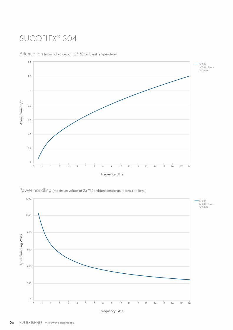
SUCOFLEX® 304
Attenuation (nominal values at +25 °C ambient temperature)
Power handling (maximum values at 25 °C ambient temperature and sea level)
Atte
nuat
ion
dB/m
Pow
er h
andl
ing
Wat
ts
Frequency GHz
Frequency GHz
HUBER+SUHNER Microwave assembliesAbbreviations see page 176 57HUBER+SUHNER Microwave assemblies 57
Hig
h
perf
orm
ance
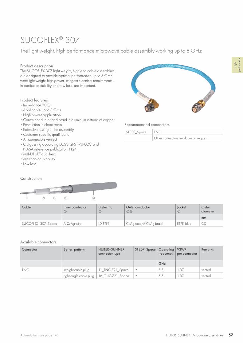
SUCOFLEX® 307 The light weight, high performance microwave cable assembly working up to 8 GHz
Product descriptionThe SUCOFLEX 307 light weight, high end cable assemblies are designed to provide optimal performance up to 8 GHz were light weight, high power, stringent electrical requirements – in particular stability and low loss, are important.
Product features• Impedance 50 Ω • Applicable up to 8 GHz• High power application • Centre conductor and braid in aluminum instead of copper• Production in clean room• Extensive testing of the assembly• Customer specific qualification• All connectors vented• Outgassing according ECSS-Q-ST-70-02C and
NASA reference publication 1124• MIL-DTL-17 qualified• Mechanical stability• Low loss
Recommended connectors
SF307_Space TNC
Other connectors available on request
Construction
Cable Inner conductor
Dielectric
Outer conductor
Jacket
Outerdiameter
mm
SUCOFLEX_307_Space AlCuAg wire LD-PTFE CuAg tape/AlCuAg braid ETFE, blue 9.0
Available connectors
Connector Series, pattern HUBER+SUHNERconnector type
SF307_Space Operatingfrequency
VSWRper connector
Remarks
GHz
TNC straight cable plug 11_TNC-721_Space • 5.5 1.07 vented
right angle cable plug 16_TNC-721_Space • 5.5 1.07 vented

HUBER+SUHNER Microwave assemblies58 HUBER+SUHNER Microwave assemblies58
Assembly types
SUCOFLEX 307_Space
Construction
Max. operating frequency GHz 8
Application static
Velocity of propagation % 77
Weight g/m 133
Min. bending radius static mm 50
Min. bending radius repeated mm 100
Temperature range °C −55 to +150
Tensile load N 340
Inner conductor solid wire
Dielectric LD-PTFE
Outer conductor tape/braid
Jacket ETFE
Outer diameter mm 9.0
Screening effectiveness(up to 18 GHz)
dB > 90
Phase stability vs. flexure(360°, diameter 125 mm)
°el/GHz < 2.0
Phase stability vs. temperature (−40 to +85 °C )
ppm < 1500
Assembly phase matching tolerances °el/GHz ± 0.5
Cable attenuation at 25 °C dB/m see graph
Insertion loss stability vs. bending dB ± 0.1
Insertion loss stability vs. temperature %/°C < 0.45
Insertion loss stability vs. shaking dB ± 0.1
Power handling watt see graph
Radiation-gamma Mrad 30
Connectors vented yes
Out gassing according ECSS-Q_ST-70-02 and NASA reference publication 1124
TML < 1 %, CVCM < 0.1 %
Soldering according to ESA qualified materials and processes ECSS-Q-70-08A andECSS-Q-70-18A
Assembling in clean room general: class 10 000working area: class 100
SUCOFLEX® 307
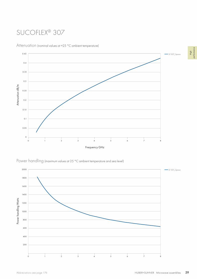
0 1 2 3 4 5 6 7 8
0 1 2 3 4 5 6 7 8
0.25
0.4
0.3
0.35
0.45
0.05
0.1
0.15
0.2
0
200
400
600
800
1000
1200
1400
1600
1800
2000
SF 307_Space
SF 307_Space
HUBER+SUHNER Microwave assembliesAbbreviations see page 176 59HUBER+SUHNER Microwave assemblies 59
Hig
h
perf
orm
ance
SUCOFLEX® 307
Attenuation (nominal values at +25 °C ambient temperature)
Power handling (maximum values at 25 °C ambient temperature and sea level)
Atte
nuat
ion
dB/m
Pow
er h
andl
ing
Wat
ts
Frequency GHz
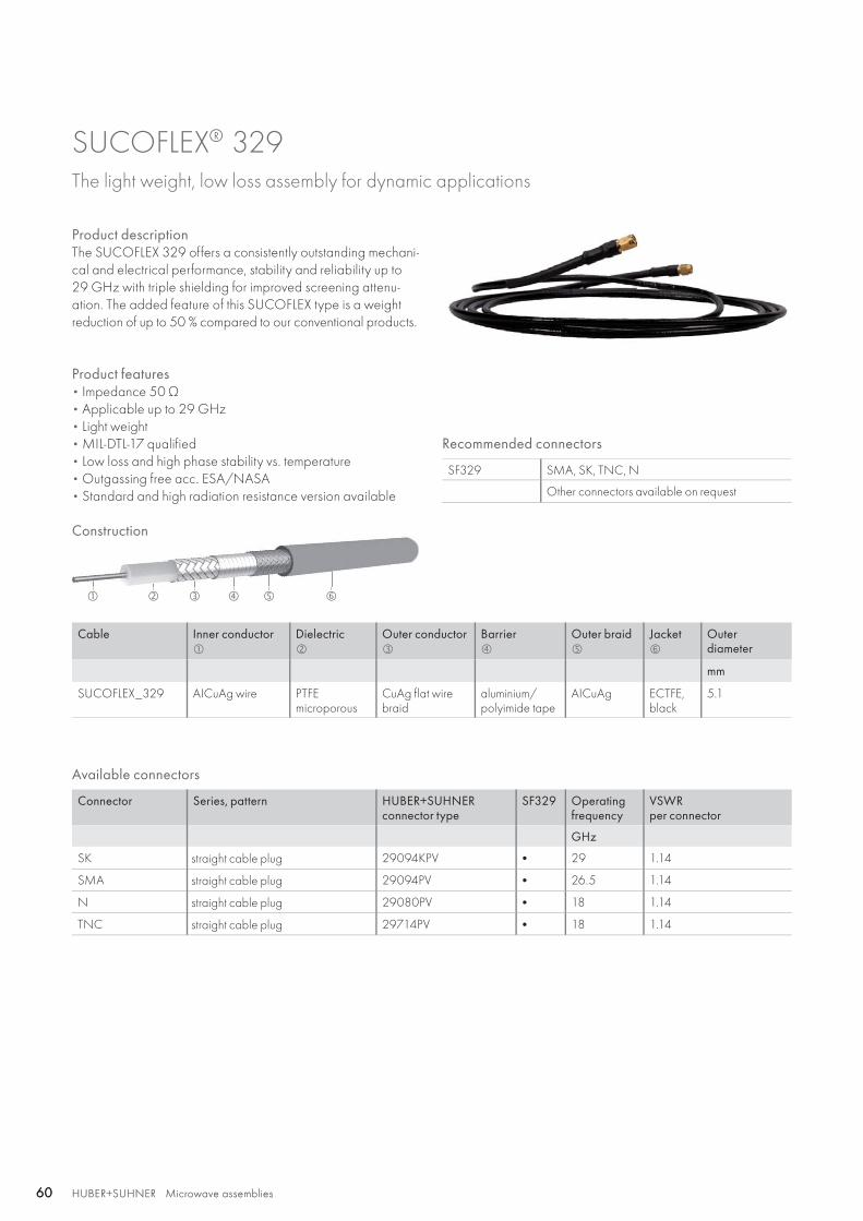
HUBER+SUHNER Microwave assemblies60 HUBER+SUHNER Microwave assemblies60
SUCOFLEX® 329 The light weight, low loss assembly for dynamic applications
Product descriptionThe SUCOFLEX 329 offers a consistently outstanding mechani-cal and electrical performance, stability and reliability up to29 GHz with triple shielding for improved screening attenu-ation. The added feature of this SUCOFLEX type is a weightreduction of up to 50 % compared to our conventional products.
Product features• Impedance 50 Ω • Applicable up to 29 GHz• Light weight• MIL-DTL-17 qualified• Low loss and high phase stability vs. temperature• Outgassing free acc. ESA/NASA• Standard and high radiation resistance version available
Recommended connectors
SF329 SMA, SK, TNC, N
Other connectors available on request
Cable Inner conductor
Dielectric
Outer conductor
Barrier
Outer braid
Jacket
Outerdiameter
mm
SUCOFLEX_329 AICuAg wire PTFEmicroporous
CuAg flat wire braid
aluminium/polyimide tape
AICuAg ECTFE,black
5.1
Construction
Available connectors
Connector Series, pattern HUBER+SUHNER connector type
SF329 Operating frequency
VSWRper connector
GHz
SK straight cable plug 29094KPV • 29 1.14
SMA straight cable plug 29094PV • 26.5 1.14
N straight cable plug 29080PV • 18 1.14
TNC straight cable plug 29714PV • 18 1.14

HUBER+SUHNER Microwave assembliesAbbreviations see page 176 61HUBER+SUHNER Microwave assemblies 61
Hig
h
perf
orm
ance
Assembly types
SUCOFLEX 329
Construction
Max. operating frequency GHz 29
Application static and dynamic
Velocity of propagation % 82
Weight g/m 40
Min. bending radius static mm 23
Min. bending radius repeated mm 70
Temperature range °C −65 to +165
Tensile load N 133
Inner conductor solid wire
Dielectric PTFE microporous
Outer conductor CuAg flat wire braid
Jacket ECTFE
Outer diameter mm 5.1
Screening effectiveness(up to 18 GHz)
dB > 90
Phase stability vs. flexure(360°, diameter 125 mm)
°el/GHz < 0.65
Phase stability vs. temperature (−55 to +85 °C )
ppm < 800
Assembly phase matching tolerances °el/GHz ± 0.5
Cable attenuation at 25 °C dB/m see graph
Insertion loss stability vs. bending dB ± 0.2
Insertion loss stability vs. temperature %/°C < 0.2
Insertion loss stability vs. shaking dB ± 0.1
Power handling watt see graph
Radiation-gamma Mrad 200
Connectors vented yes
Out gassing according ECSS-Q_ST-70-02 and NASA reference publication 1124
TML < 1 %, CVCM < 0.1 %
Soldering according to ESA qualified materials and processes J-STD-001ES
Assembling in clean room class 100 000
SUCOFLEX® 329
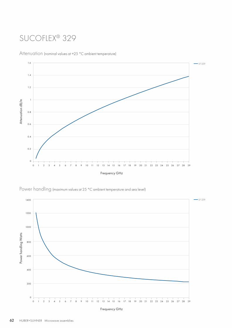
SF 329
SF 329
1
1.2
1.4
1.6
200
400
600
800
1000
1200
0.2
0.4
0.6
0.8
0
0
0 1 2 3 4 5 6 7 8 9 10 11 12 13 14 15 16 17 18 19 20 21 22 23 24 25 26 27 28 29
0 1 2 3 4 5 6 7 8 9 10 11 12 13 14 15 16 17 18 19 20 21 22 23 24 25 26 27 28 29
1400
HUBER+SUHNER Microwave assemblies62 HUBER+SUHNER Microwave assemblies62
SUCOFLEX® 329
Attenuation (nominal values at +25 °C ambient temperature)
Power handling (maximum values at 25 °C ambient temperature and sea level)
Atte
nuat
ion
dB/m
Pow
er h
andl
ing
Wat
ts
Frequency GHz
Frequency GHz

HUBER+SUHNER Microwave assembliesAbbreviations see page 176 63HUBER+SUHNER Microwave assemblies 63
Hig
h
perf
orm
ance
SUCOFLEX® 340 The light weight, low loss assembly for dynamic applications
Product descriptionThe SUCOFLEX 340 offers a consistently outstanding mechani-cal and electrical performance, stability and reliability up to40 GHz with triple shielding for improved screening attenu-ation. The added feature of this SUCOFLEX type is a weightreduction of up to 50 % compared to our conventional products.
Product features• Impedance 50 Ω• Applicable up to 40 GHz• Light weight• MIL-DTL-17 qualified• Low loss and high phase stability vs. temperature• Outgassing free acc. ESA/NASA• Standard and high radiation resistance version available
Recommended connectors
SF340 SMA, SK
Other connectors available on request
Cable Inner conductor
Dielectric
Outer conductor
Barrier
Outer braid
Jacket
Outer diameter
mm
SUCOFLEX_340 AICuAg wire PTFEmicroporous
CuAg flat wire braid
aluminium/polyimide tape
AICuAg ECTFE, black
4.2
Construction
Available connectors
Connector Series, pattern HUBER+SUHNERconnector type
SF340 Operating frequency VSWRper connector
GHz
SK straight cable plug 29094KPV • 40 1.14
SMA straight cable plug 29094PV • 26.5 1.14
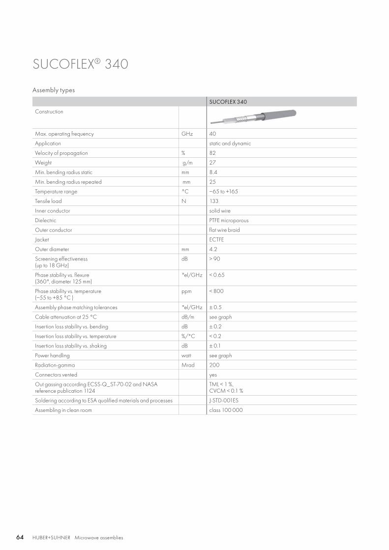
HUBER+SUHNER Microwave assemblies64 HUBER+SUHNER Microwave assemblies64
Assembly types
SUCOFLEX 340
Construction
Max. operating frequency GHz 40
Application static and dynamic
Velocity of propagation % 82
Weight g/m 27
Min. bending radius static mm 8.4
Min. bending radius repeated mm 25
Temperature range °C −65 to +165
Tensile load N 133
Inner conductor solid wire
Dielectric PTFE microporous
Outer conductor flat wire braid
Jacket ECTFE
Outer diameter mm 4.2
Screening effectiveness(up to 18 GHz)
dB > 90
Phase stability vs. flexure(360°, diameter 125 mm)
°el/GHz < 0.65
Phase stability vs. temperature (−55 to +85 °C )
ppm < 800
Assembly phase matching tolerances °el/GHz ± 0.5
Cable attenuation at 25 °C dB/m see graph
Insertion loss stability vs. bending dB ± 0.2
Insertion loss stability vs. temperature %/°C < 0.2
Insertion loss stability vs. shaking dB ± 0.1
Power handling watt see graph
Radiation-gamma Mrad 200
Connectors vented yes
Out gassing according ECSS-Q_ST-70-02 and NASA reference publication 1124
TML < 1 %, CVCM < 0.1 %
Soldering according to ESA qualified materials and processes J-STD-001ES
Assembling in clean room class 100 000
SUCOFLEX® 340
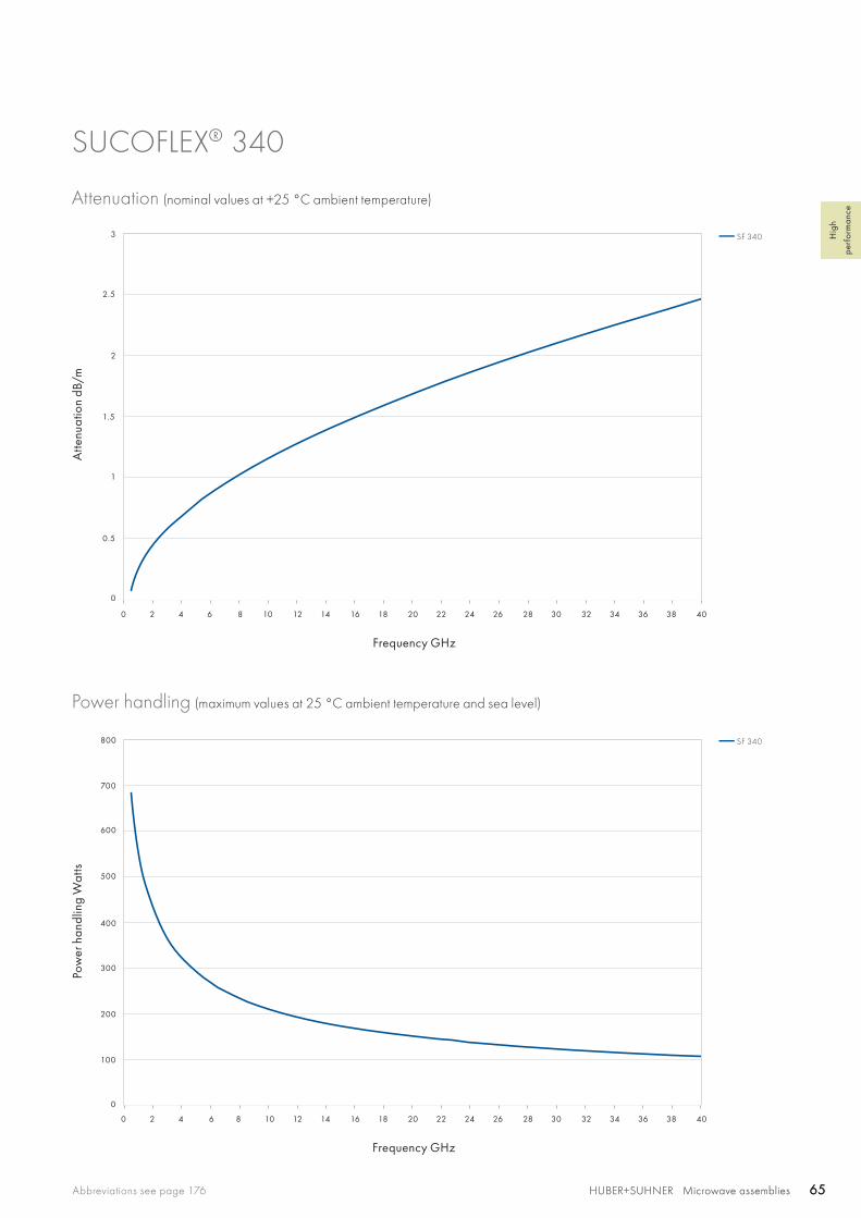
SF 340
SF 340
3
2.5
2
1.5
1
0.5
100
200
300
400
500
0
0
0 2 4 6 8 10 12 14 16 18 20 22 24 26 28 30 32 34 36 38 40
0 2 4 6 8 10 12 14 16 18 20 22 24 26 28 30 32 34 36 38 40
600
700
800
HUBER+SUHNER Microwave assembliesAbbreviations see page 176 65HUBER+SUHNER Microwave assemblies 65
Hig
h
perf
orm
ance
SUCOFLEX® 340
Attenuation (nominal values at +25 °C ambient temperature)
Power handling (maximum values at 25 °C ambient temperature and sea level)
Atte
nuat
ion
dB/m
Pow
er h
andl
ing
Wat
ts
Frequency GHz
Frequency GHz
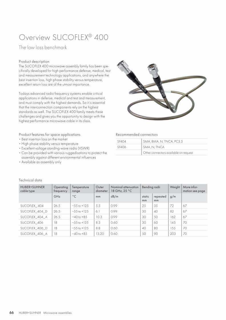
HUBER+SUHNER Microwave assemblies66 HUBER+SUHNER Microwave assemblies66
Overview SUCOFLEX® 400The low loss benchmark
Product descriptionThe SUCOFLEX 400 microwave assembly family has been spe-cifically developed for high performance defense, medical, test and measurement technology applications, and anywhere the best insertion loss, high phase stability versus temperature, excellent return loss are of the utmost importance.
Todays advanced radio frequency systems enable critical applications in defense, medical and test and measurement, and must comply with the highest demands. So it is essential that the interconnection components rely on the highest standards as well. The SUCOFLEX 400 family meets these challenges and gives you the opportunity to design with the highest performance microwave cable in its class.
Product features for space applications• Best insertion loss on the market• High phase stability versus temperature• Excellent voltage standing wave radio (VSWR)• Can be provided with various ruggedisations to protect the
assembly against different environmental influences• Available as assembly only
Recommended connectors
SF404 SMA, BMA, N, TNCA, PC3.5
SF406 SMA, N, TNCA
Other connectors available on request
Technical data
HUBER+SUHNER cable type
Operating frequency
Temperature range
Outer diameter
Nominal attenuation 18 GHz, 25 °C
Bending radii Weight More infor-mation see page
GHz °C mm dB/m staticmm
repeated mm
g/m
SUCOFLEX_ 404 26.5 −55 to +125 5.5 0.99 25 35 72 67
SUCOFLEX_404_D 26.5 −55 to +125 6.1 0.99 30 40 82 67
SUCOFLEX_404_A 26.5 −40 to +85 10.3 0.99 30 50 162 67
SUCOFLEX_406 18 −55 to +125 8.3 0.60 30 60 145 70
SUCOFLEX_406_D 18 −55 to +125 8.8 0.60 40 80 155 70
SUCOFLEX_406_A 18 −40 to +85 13.20 0.60 50 90 203 70
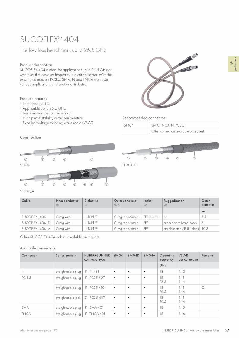
SF 404
SF 404_A
SF 404_D
HUBER+SUHNER Microwave assembliesAbbreviations see page 176 67HUBER+SUHNER Microwave assemblies 67
Hig
h
perf
orm
ance
SUCOFLEX® 404 The low loss benchmark up to 26.5 GHz
Product descriptionSUCOFLEX 404 is ideal for applications up to 26.5 GHz or wherever the loss over frequency is a critical factor. With the existing connectors PC3.5, SMA, N and TNCA we cover various applications and sectors of industry.
Product features• Impedance 50 Ω • Applicable up to 26.5 GHz• Best insertion loss on the market• High phase stability versus temperature• Excellent voltage standing wave radio (VSWR)
Recommended connectors
SF404 SMA, TNCA, N, PC3.5
Other connectors available on request
Construction
Cable Inner conductor
Dielectric
Outer conductor
Jacket
Ruggedisation
Outerdiameter
mm
SUCOFLEX_404 CuAg wire ULD-PTFE CuAg tape/braid FEP, brown no 5.5
SUCOFLEX_404_D CuAg wire ULD-PTFE CuAg tape/braid FEP aramid yarn braid, black 6.1
SUCOFLEX_404_A CuAg wire ULD-PTFE CuAg tape/braid FEP stainless steel/PUR, black 10.3
Other SUCOFLEX 404 cables available on request.
Available connectors
Connector Series, pattern HUBER+SUHNERconnector type
SF404 SF404D SF404A Operatingfrequency
VSWRper connector
Remarks
GHz
N straight cable plug 11_N-431 • • • 18 1.12
PC 3.5 straight cable plug 11_PC35-407 • • • 1826.5
1.111.14
straight cable plug 11_PC35-410 • • • 1826.5
1.111.14
QL
straight cable jack 21_PC35-407 • • • 1826.5
1.111.14
SMA straight cable plug 11_SMA-401 • • • 18 1.15
TNCA straight cable plug 11_TNCA-401 • • • 18 1.16

HUBER+SUHNER Microwave assemblies68 HUBER+SUHNER Microwave assemblies68
SUCOFLEX® 404
Assembly types
SUCOFLEX 404 SUCOFLEX 404D SUCOFLEX 404A
Construction
Max. operating frequency GHz 26.5 26.5 26.5
Application static static static
Velocity of propagation % 89 89 89
Weight g/m 72 82 162
Min. bending radius static mm 25 30 30
Min. bending radius repeated mm 35 40 50
Temperature range °C −55 to +125 −55 to +125 −40 to +85
Crush resistance kN/m 2 5 80
Tensile load N 115 115 500
Inner conductor solid wire solid wire solid wire
Dielectric ULD-PTFE ULD-PTFE ULD-PTFE
Outer conductor tape/braid tape/braid tape/braid
Jacket FEP FEP FEP
Ruggedisation no aramid yarn braid stainless steel/PUR
Outer diameter mm 5.5 6.1 10.3
Screening effectiveness(up to 18 GHz)
dB > 90 > 90 > 90
Phase stability vs. flexure(360°, diameter 55 mm)
°el/GHz < 1.7 < 1.7 < 1.7
Phase stability vs. temperature (−40 to +85 °C )
ppm < 500 < 500 < 500
Assembly phase matching tolerances °el/GHz ± 0.5 ± 0.5 ± 0.5
Cable attenuation at 25 °C dB/m see graph see graph see graph
Insertion loss stability vs. bending dB ± 0.1 ± 0.1 ± 0.1
Insertion loss stability vs. temperature %/°C < 0.26 < 0.26 < 0.26
Insertion loss stability vs. shaking dB ± 0.2 ± 0.2 ± 0.2
Power handling watt see graph see graph see graph
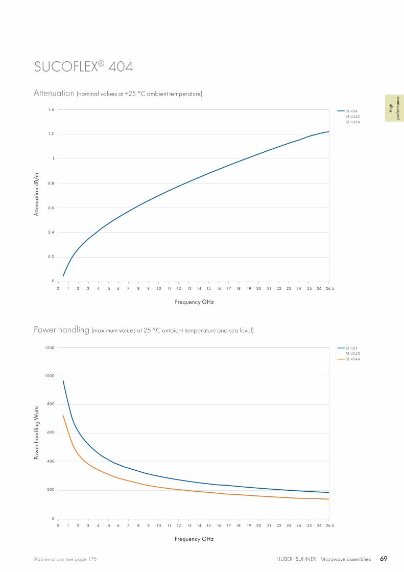
SF 404SF 404DSF 404A
SF 404SF 404DSF 404A
1
1.4
1.2
0.2
0.4
0.6
0.8
0
0 1 2 3 4 5 6 7 8 9 10 11 12 13 14 15 16 17 18 19 20 21 22 23 24 25 26 26.5
200
400
600
800
1000
1200
0
0 1 2 3 4 5 6 7 8 9 10 11 12 13 14 15 16 17 18 19 20 21 22 23 24 25 26 26.5
HUBER+SUHNER Microwave assembliesAbbreviations see page 176 69HUBER+SUHNER Microwave assemblies 69
Hig
h
perf
orm
ance
SUCOFLEX® 404
Attenuation (nominal values at +25 °C ambient temperature)
Power handling (maximum values at 25 °C ambient temperature and sea level)
Atte
nuat
ion
dB/m
Pow
er h
andl
ing
Wat
ts
Frequency GHz
Frequency GHz
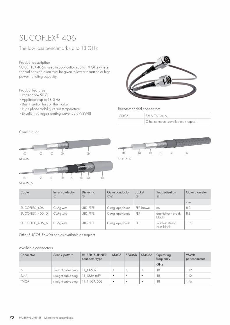
SF 406
SF 406_A
SF 406_D
HUBER+SUHNER Microwave assemblies70 HUBER+SUHNER Microwave assemblies70
SUCOFLEX® 406 The low loss benchmark up to 18 GHz
Product descriptionSUCOFLEX 406 is used in applications up to 18 GHz where special consideration must be given to low attenuation or high power handling capacity.
Product features• Impedance 50 Ω • Applicable up to 18 GHz• Best insertion loss on the market• High phase stability versus temperature• Excellent voltage standing wave radio (VSWR)
Construction
Cable Inner conductor
Dielectric
Outer conductor
Jacket
Ruggedisation
Outer diameter
mm
SUCOFLEX_406 CuAg wire ULD-PTFE CuAg tape/braid FEP, brown no 8.3
SUCOFLEX_406_D CuAg wire ULD-PTFE CuAg tape/braid FEP aramid yarn braid, black
8.8
SUCOFLEX_406_A CuAg wire ULD-PTFE CuAg tape/braid FEP stainless steel/PUR, black
13.2
Other SUCOFLEX 406 cables available on request.
Available connectors
Connector Series, pattern HUBER+SUHNERconnector type
SF406 SF406D SF406A Operatingfrequency
VSWRper connector
GHz
N straight cable plug 11_N-632 • • • 18 1.12
SMA straight cable plug 11_SMA-659 • • • 18 1.12
TNCA straight cable plug 11_TNCA-602 • • • 18 1.16
Recommended connectors
SF406 SMA, TNCA, N,
Other connectors available on request

HUBER+SUHNER Microwave assembliesAbbreviations see page 176 71HUBER+SUHNER Microwave assemblies 71
Hig
h
perf
orm
ance
SUCOFLEX® 406
Assembly types
SUCOFLEX 406 SUCOFLEX 406D SUCOFLEX 406A
Construction
Max. operating frequency GHz 18 18 18
Application static static static
Velocity of propagation % 89 89 89
Weight g/m 145 155 203
Min. bending radius static mm 30 40 50
Min. bending radius repeated mm 60 80 90
Temperature range °C −55 to +125 −55 to +125 −40 to +85
Crush resistance kN/m 6 7.5 80
Tensile load N 175 175 500
Inner conductor solid wire solid wire solid wire
Dielectric ULD-PTFE ULD-PTFE ULD-PTFE
Outer conductor tape/braid tape/braid tape/braid
Jacket FEP FEP FEP
Ruggedisation no aramid yarn braid stainless steel/PUR
Outer diameter mm 8.3 8.8 13.2
Screening effectiveness(up to 18 GHz)
dB > 90 > 90 > 90
Phase stability vs. flexure(360°, diameter 85 mm)
°el/GHz < 2.5 < 2.5 < 2.5
Phase stability vs. temperature (−40 to +85 °C )
ppm < 500 < 500 < 500
Assembly phase matching tolerances °el/GHz ± 0.5 ± 0.5 ± 0.5
Cable attenuation at 25 °C dB/m see graph see graph see graph
Insertion loss stability vs. bending dB ± 0.1 ± 0.1 ± 0.1
Insertion loss stability vs. temperature %/°C < 0.26 < 0.26 < 0.26
Insertion loss stability vs. shaking dB ± 0.1 ± 0.1 ± 0.1
Power handling watt see graph see graph see graph
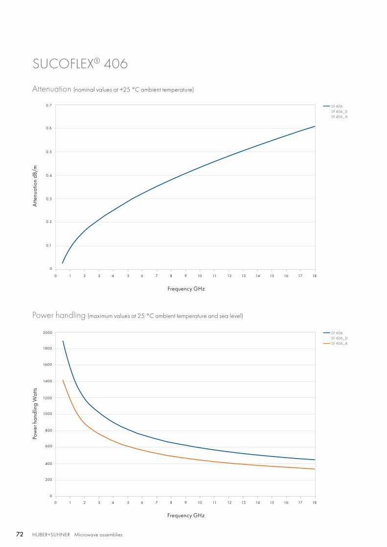
SF 406SF 406_DSF 406_A
SF 406SF 406_DSF 406_A
0.1
0.2
0.3
0.4
0.5
0.6
0.7
0
0 1 2 3 4 5 6 7 8 9 10 11 12 13 14 15 16 17 18
0
200
400
600
800
1000
1200
1400
1600
1800
2000
HUBER+SUHNER Microwave assemblies72 HUBER+SUHNER Microwave assemblies72
SUCOFLEX® 406
Attenuation (nominal values at +25 °C ambient temperature)
Power handling (maximum values at 25 °C ambient temperature and sea level)
Atte
nuat
ion
dB/m
Pow
er h
andl
ing
Wat
ts
Frequency GHz
Frequency GHz
0 1 2 3 4 5 6 7 8 9 10 11 12 13 14 15 16 17 18

HUBER+SUHNER Microwave assembliesAbbreviations see page 176 73HUBER+SUHNER Microwave assemblies 73
Hig
h
perf
orm
ance

74 HUBER+SUHNER Microwave assemblies
Qualified, low profile microwavecable assemblies Minibend is a truly flexible coaxial cable assembly which is designed for use in low profile, internal, point-to-point interconnections between RF modules within communications systems. Minibend replaces custom semi-rigid cables with standard flexible cables, eliminating the need for prede-fined custom lengths and bend configurations. Minibend provides you with a preassembled and tested high performance, cost-effective alternative in a variety of standard lengths and connector configurations.
Minibend R is designed for use in complex, congested environments where higher cable retention force is required. Minibend R's pull strength is more than 70 % greater than a standard Minibend. When installed and bent at the minimum bend radius, Minibend R will tolerate multiple 90° rota-tions at the cable/connector junction. The "R" ruggedisation can be added to any Minibend connector style. All materials used in Minibend R assemblies meet or exceed NASA TML and CVCM requirements for use in spacecraft applications.
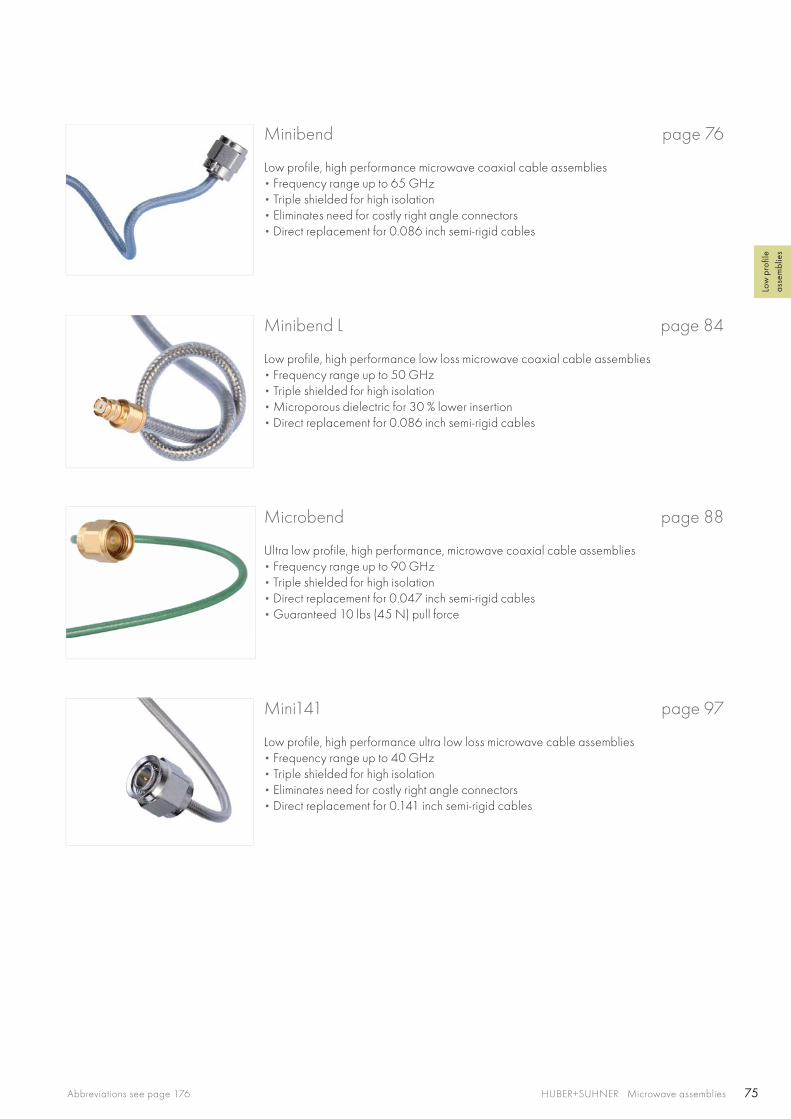
75HUBER+SUHNER Microwave assembliesAbbreviations see page 176
Low
pro
file
asse
mbl
ies
Minibend L page 84
Low profile, high performance low loss microwave coaxial cable assemblies• Frequency range up to 50 GHz • Triple shielded for high isolation• Microporous dielectric for 30 % lower insertion • Direct replacement for 0.086 inch semi-rigid cables
Microbend page 88
Ultra low profile, high performance, microwave coaxial cable assemblies• Frequency range up to 90 GHz • Triple shielded for high isolation• Direct replacement for 0.047 inch semi-rigid cables• Guaranteed 10 lbs (45 N) pull force
Minibend page 76
Low profile, high performance microwave coaxial cable assemblies• Frequency range up to 65 GHz • Triple shielded for high isolation• Eliminates need for costly right angle connectors • Direct replacement for 0.086 inch semi-rigid cables
Mini141 page 97
Low profile, high performance ultra low loss microwave cable assemblies• Frequency range up to 40 GHz • Triple shielded for high isolation• Eliminates need for costly right angle connectors• Direct replacement for 0.141 inch semi-rigid cables
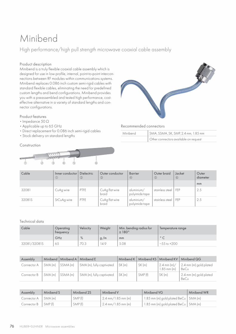
76
HUBER+SUHNER Microwave assemblies
MinibendHigh performance/high pull strength microwave coaxial cable assembly
Product descriptionMinibend is a truly flexible coaxial cable assembly which is designed for use in low profile, internal, point-to-point intercon-nections between RF modules within communications systems. Minibend replaces 0.086 inch custom semi-rigid cables with standard flexible cables, eliminating the need for predefined custom lengths and bend configurations. Minibend provides you with a preassembled and tested high performance, cost-effective alternative in a variety of standard lengths and con-nector configurations.
Product features• Impedance 50 Ω • Applicable up to 65 GHz• Direct replacement for 0.086 inch semi-rigid cables• Stock delivery on standard lengths
Construction
Recommended connectors
Minibend SMA, SSMA, SK, SMP, 2.4 mm, 1.85 mm
Other connectors available on request
Cable Inner conductor
Dielectric
Outer conductor
Barrier
Outer braid
Jacket
Outerdiameter
mm
32081 CuAg wire PTFE CuAg flat wire braid
aluminium/polyimide tape
stainless steel FEP 2.5
32081S StCuAg wire PTFE CuAg flat wire braid
aluminium/polyimide tape
stainless steel FEP 2.5
Technical data
Cable Operating frequency
Velocity Weight Min. bending radius for± 180°
Temperature range
GHz % g /m mm ° C
32081/32081S 65 70.3 14.9 5.08 −55 to +200
Assembly Minibend Minibend A Minibend E Minibend K Minibend KS Minibend KV Minibend QG
Connector A SMA (m) SSMA (m) SMA (m), fully captivated SK (m) SK (m) 2.4 mm (m)/1.85 mm (m)
2.4 mm (m) gold plated BeCu
Connector B SMA (m) SSMA (m) SMA (m), fully captivated SK (m) SMP (f) SK (m) 2.4 mm (m) gold plated BeCu
Assembly Minibend S Minibend 2S Minibend V Minibend VG Minibend WR
Connector A SMA (m) SMP (f) 2.4 mm/1.85 mm (m) 1.85 mm (m) gold plated BeCu SMA (m)
Connector B SMP (f) SMP (f) 2.4 mm/1.85 mm (m) 1.85 mm (m) gold plated BeCu SMA (m)
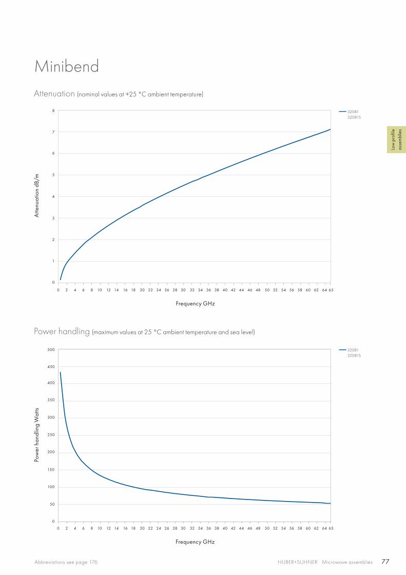
77
0 2 4 6 8 10 12 14 16 18 20 22 24 26 28 30 32 34 36 38 40 42 44 46 48 50 52 54 56 58 60 62 64 65
0 2 4 6 8 10 12 14 16 18 20 22 24 26 28 30 32 34 36 38 40 42 44 46 48 50 52 54 56 58 60 62 64 65
3
4
5
6
7
8
2
150
200
250
300
350
400
450
500
1
100
50
0
0
HUBER+SUHNER Microwave assembliesAbbreviations see page 176
Low
pro
file
asse
mbl
ies
MinibendAttenuation (nominal values at +25 °C ambient temperature)
Power handling (maximum values at 25 °C ambient temperature and sea level)
Atte
nuat
ion
dB/m
Pow
er h
andl
ing
Wat
ts
Frequency GHz
Frequency GHz
3208132081S
3208132081S
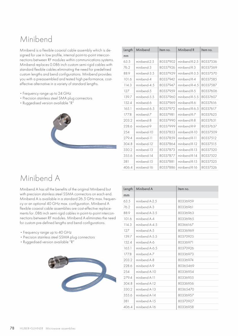
78 HUBER+SUHNER Microwave assemblies
MinibendMinibend is a flexible coaxial cable assembly which is de-signed for use in low profile, internal point-to-point intercon-nections between RF modules within communications systems. Minibend replaces 0.086 inch custom semi-rigid cables with standard flexible cables eliminating the need for predefined custom lengths and bend configurations. Minibend provides you with a preassembled and tested high performance, cost-effective alternative in a variety of standard lengths.
• Frequency range up to 24 GHz• Precision stainless steel SMA plug connectors • Ruggedised version available "R"
Length Minibend Item no. Minibend R Item no.
mm
63.5 minibend-2.5 80337902 minibend R-2.5 80337536
76.2 minibend-3 80337926 minibend R-3 80337569
88.9 minibend-3.5 80337929 minibend R-3.5 80337570
101.6 minibend-4 80337942 minibend R-4 80337585
114.3 minibend-4.5 80337947 minibend R-4.5 80337587
127 minibend-5 80337959 minibend R-5 80337606
139.7 minibend-5.5 80337960 minibend R-5.5 80337607
152.4 minibend-6 80337969 minibend R-6 80337616
165.1 minibend-6.5 80337972 minibend R-6.5 80337617
177.8 minibend-7 80337981 minibend R-7 80337625
203.2 minibend-8 80337990 minibend R-8 80337631
228.6 minibend-9 80337999 minibend R-9 80337637
254 minibend-10 80337853 minibend R-10 80337509
279.4 minibend-11 80337859 minibend R-11 80337512
304.8 minibend-12 80337864 minibend R-12 80337515
330.2 minibend-13 80337873 minibend R-13 80337520
355.6 minibend-14 80337877 minibend R-14 80337522
381 minibend-15 80337881 minibend R-15 80337525
406.4 minibend-16 80337886 minibend R-16 80337526
Length Minibend A Item no.
mm63.5 minibend A-2.5 80336959
76.2 minibend A-3 80336961
88.9 minibend A-3.5 80336963
101.6 minibend A-4 80336965
114.3 minibend A-4.5 80366167
127 minibend A-5 80336969
139.7 minibend A-5.5 80370925
152.4 minibend A-6 80336971
165.1 minibend A-6.5 80370926
177.8 minibend A-7 80336973
203.2 minibend A-8 80336974
228.6 minibend A-9 80365469
254 minibend A-10 80336954
279.4 minibend A-11 80336955
304.8 minibend A-12 80336956
330.2 minibend A-13 80365470
355.6 minibend A-14 80336957
381 minibend A-15 80370927
406.4 minibend A-16 80336958
Minibend AMinibend A has all the benefits of the original Minibend but with precision stainless steel SSMA connectors on each end. Minibend A is available in a standard 26.5 GHz max. frequen-cy or an optional 40 GHz max. configuration. Minibend A flexible coaxial cable assemblies are cost-effective replace-ments for .086 inch semi-rigid cables in point-to-point intercon-nections between RF modules. Minibend A eliminates the need for custom pre-defined lengths and bend configurations.
• Frequency range up to 40 GHz• Precision stainless steel SSMA plug connectors • Ruggedised version available "R"
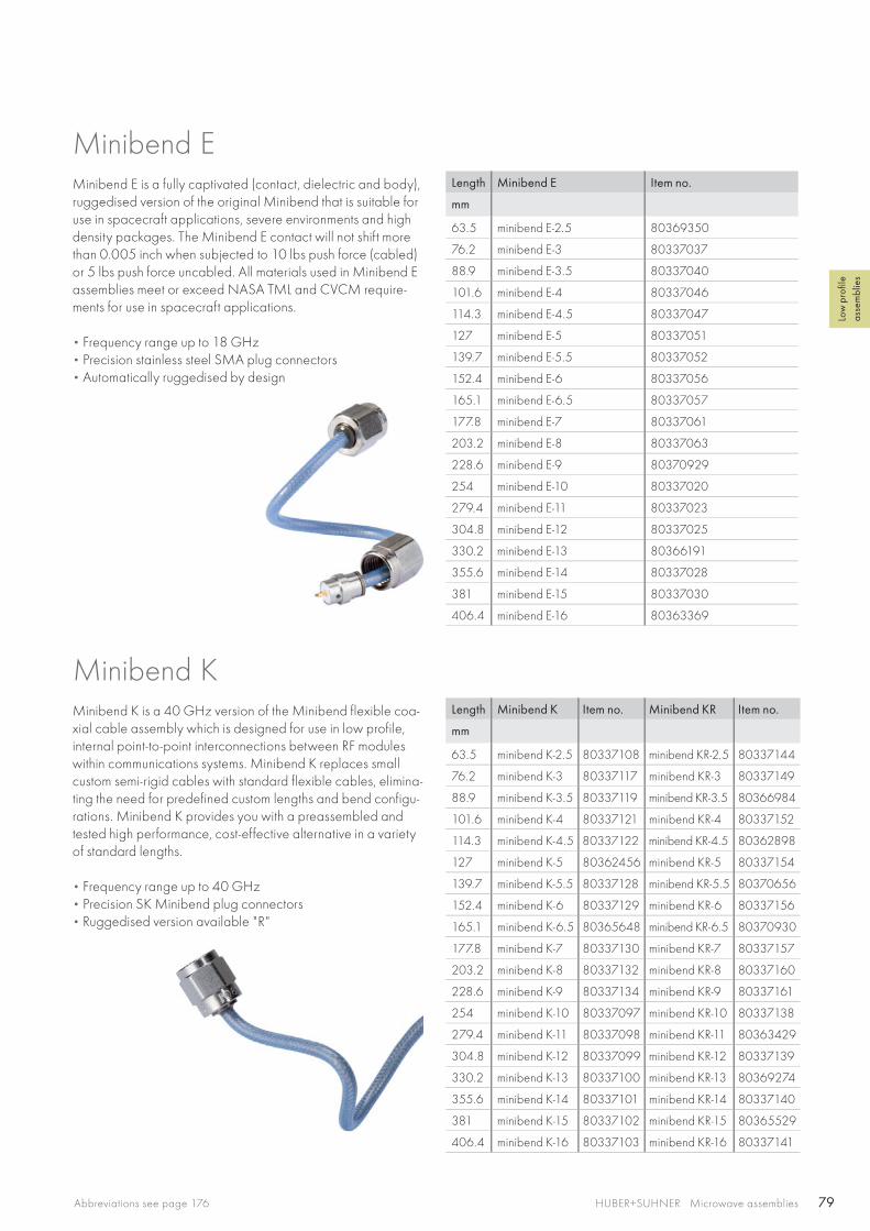
79HUBER+SUHNER Microwave assembliesAbbreviations see page 176
Low
pro
file
asse
mbl
ies
Length Minibend E Item no.
mm
63.5 minibend E-2.5 80369350
76.2 minibend E-3 80337037
88.9 minibend E-3.5 80337040
101.6 minibend E-4 80337046
114.3 minibend E-4.5 80337047
127 minibend E-5 80337051
139.7 minibend E-5.5 80337052
152.4 minibend E-6 80337056
165.1 minibend E-6.5 80337057
177.8 minibend E-7 80337061
203.2 minibend E-8 80337063
228.6 minibend E-9 80370929
254 minibend E-10 80337020
279.4 minibend E-11 80337023
304.8 minibend E-12 80337025
330.2 minibend E-13 80366191
355.6 minibend E-14 80337028
381 minibend E-15 80337030
406.4 minibend E-16 80363369
Length Minibend K Item no. Minibend KR Item no.
mm
63.5 minibend K-2.5 80337108 minibend KR-2.5 80337144
76.2 minibend K-3 80337117 minibend KR-3 80337149
88.9 minibend K-3.5 80337119 minibend KR-3.5 80366984
101.6 minibend K-4 80337121 minibend KR-4 80337152
114.3 minibend K-4.5 80337122 minibend KR-4.5 80362898
127 minibend K-5 80362456 minibend KR-5 80337154
139.7 minibend K-5.5 80337128 minibend KR-5.5 80370656
152.4 minibend K-6 80337129 minibend KR-6 80337156
165.1 minibend K-6.5 80365648 minibend KR-6.5 80370930
177.8 minibend K-7 80337130 minibend KR-7 80337157
203.2 minibend K-8 80337132 minibend KR-8 80337160
228.6 minibend K-9 80337134 minibend KR-9 80337161
254 minibend K-10 80337097 minibend KR-10 80337138
279.4 minibend K-11 80337098 minibend KR-11 80363429
304.8 minibend K-12 80337099 minibend KR-12 80337139
330.2 minibend K-13 80337100 minibend KR-13 80369274
355.6 minibend K-14 80337101 minibend KR-14 80337140
381 minibend K-15 80337102 minibend KR-15 80365529
406.4 minibend K-16 80337103 minibend KR-16 80337141
Minibend E is a fully captivated (contact, dielectric and body), ruggedised version of the original Minibend that is suitable for use in spacecraft applications, severe environments and high density packages. The Minibend E contact will not shift more than 0.005 inch when subjected to 10 lbs push force (cabled) or 5 lbs push force uncabled. All materials used in Minibend E assemblies meet or exceed NASA TML and CVCM require-ments for use in spacecraft applications.
• Frequency range up to 18 GHz • Precision stainless steel SMA plug connectors • Automatically ruggedised by design
Minibend E
Minibend KMinibend K is a 40 GHz version of the Minibend flexible coa-xial cable assembly which is designed for use in low profile, internal point-to-point interconnections between RF modules within communications systems. Minibend K replaces small custom semi-rigid cables with standard flexible cables, elimina-ting the need for predefined custom lengths and bend configu-rations. Minibend K provides you with a preassembled and tested high performance, cost-effective alternative in a variety of standard lengths.
• Frequency range up to 40 GHz • Precision SK Minibend plug connectors• Ruggedised version available "R"
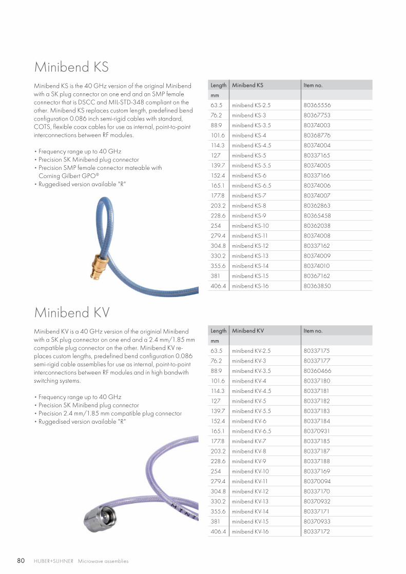
80 HUBER+SUHNER Microwave assemblies
Length Minibend KS Item no.
mm
63.5 minibend KS-2.5 80365556
76.2 minibend KS-3 80367753
88.9 minibend KS-3.5 80374003
101.6 minibend KS-4 80368776
114.3 minibend KS-4.5 80374004
127 minibend KS-5 80337165
139.7 minibend KS-5.5 80374005
152.4 minibend KS-6 80337166
165.1 minibend KS-6.5 80374006
177.8 minibend KS-7 80374007
203.2 minibend KS-8 80362863
228.6 minibend KS-9 80365458
254 minibend KS-10 80362038
279.4 minibend KS-11 80374008
304.8 minibend KS-12 80337162
330.2 minibend KS-13 80374009
355.6 minibend KS-14 80374010
381 minibend KS-15 80367162
406.4 minibend KS-16 80363850
Length Minibend KV Item no.
mm
63.5 minibend KV-2.5 80337175
76.2 minibend KV-3 80337177
88.9 minibend KV-3.5 80360466
101.6 minibend KV-4 80337180
114.3 minibend KV-4.5 80337181
127 minibend KV-5 80337182
139.7 minibend KV-5.5 80337183
152.4 minibend KV-6 80337184
165.1 minibend KV-6.5 80370931
177.8 minibend KV-7 80337185
203.2 minibend KV-8 80337187
228.6 minibend KV-9 80337188
254 minibend KV-10 80337169
279.4 minibend KV-11 80370094
304.8 minibend KV-12 80337170
330.2 minibend KV-13 80370932
355.6 minibend KV-14 80337171
381 minibend KV-15 80370933
406.4 minibend KV-16 80337172
Minibend KSMinibend KS is the 40 GHz version of the original Minibend with a SK plug connector on one end and an SMP female connector that is DSCC and MIL-STD-348 compliant on the other. Minibend KS replaces custom length, predefined bend configuration 0.086 inch semi-rigid cables with standard, COTS, flexible coax cables for use as internal, point-to-point interconnections between RF modules.
• Frequency range up to 40 GHz • Precision SK Minibend plug connector• Precision SMP female connector mateable with
Corning Gilbert GPO® • Ruggedised version available "R"
Minibend KV is a 40 GHz version of the originial Minibend with a SK plug connector on one end and a 2.4 mm/1.85 mm compatible plug connector on the other. Minibend KV re-places custom lengths, predefined bend configuration 0.086 semi-rigid cable assemblies for use as internal, point-to-point interconnections between RF modules and in high bandwith switching systems.
• Frequency range up to 40 GHz • Precision SK Minibend plug connector• Precision 2.4 mm/1.85 mm compatible plug connector• Ruggedised version available "R"
Minibend KV

81HUBER+SUHNER Microwave assembliesAbbreviations see page 176
Low
pro
file
asse
mbl
ies
Length Minibend QG Item no.
mm
63.5 minibend QG-2.5 80370934
76.2 minibend QG-3 80361835
88.9 minibend QG-3.5 80370203
101.6 minibend QG-4 80337502
114.3 minibend QG-4.5 80367704
127 minibend QG-5 80365999
139.7 minibend QG-5.5 80370935
152.4 minibend QG-6 80362867
165.1 minibend QG-6.5 80366000
177.8 minibend QG-7 80371525
203.2 minibend QG-8 80337503
228.6 minibend QG-9 80371780
254 minibend QG-10 80363167
279.4 minibend QG-11 80367645
304.8 minibend QG-12 80362486
330.2 minibend QG-13 80370936
355.6 minibend QG-14 80370937
381 minibend QG-15 80370938
406.4 minibend QG-16 80370939
Length Minibend S Item no. Minibend SR Item no.
mm
63.5 minibend S-2.5 80337655 minibend SR-2.5 80337687
76.2 minibend S-3 80337657 minibend SR-3 80337692
88.9 minibend S-3.5 80370940 minibend SR-3.5 80337693
101.6 minibend S-4 80337658 minibend SR-4 80337698
114.3 minibend S-4.5 80337660 minibend SR-4.5 80337699
127 minibend S-5 80337661 minibend SR-5 80337704
139.7 minibend S-5.5 80337662 minibend SR-5.5 80365201
152.4 minibend S-6 80337663 minibend SR-6 80337707
165.1 minibend S-6.5 80367381 minibend SR-6.5 80370944
177.8 minibend S-7 80337665 minibend SR-7 80337710
203.2 minibend S-8 80337666 minibend SR-8 80337712
228.6 minibend S-9 80337670 minibend SR-9 80362779
254 minibend S-10 80337641 minibend SR-10 80337678
279.4 minibend S-11 80337642 minibend SR-11 80337680
304.8 minibend S-12 80337644 minibend SR-12 80337681
330.2 minibend S-13 80365405 minibend SR-13 80370945
355.6 minibend S-14 80337646 minibend SR-14 80337682
381 minibend S-15 80337647 minibend SR-15 80370946
406.4 minibend S-16 80337649 minibend SR-16 80337683
Minibend QGMinibend QG is a 50 GHz version of the original Minibend with a 2.4 mm plug connector on each end that contains a gold plated BeCu contact for applications that require repea-ted mates/demates of the interface. This flexible coaxial cable assembly is designed for use in low profile, internal point-to-point interconnections between RF modules within communica-tions systems. Minibend QG replaces small custom semi-rigid cables with standard flexible cables, eliminating the need for predefined custom lengths and bend configurations. Minibend QG provides you with a preassembled and tested high perfor-mance, cost-effective alternative in a variety of standard lengths.
• Frequency range up to 50 GHz • Precision 2.4 mm compatible plug connectors • Automatically ruggedised by design
Minibend S is a special version of the original Minibend that provides all the benefits of the original Minibend but with a precision DSCC and MIL-STD-348 compliant SMP female connector on one end and an SMA plug connector on the other. Minibend S replaces custom length, predefined bend configuration cable for use as internal, point-to-point intercon-nections between RF modules within communications and switching systems.
• Frequency range up to 24 GHz • Precision stainless steel SMA plug connectors • Precision SMP female connector mateable with
Corning Gilbert GPO® • Ruggedised version available "R"
Minibend S
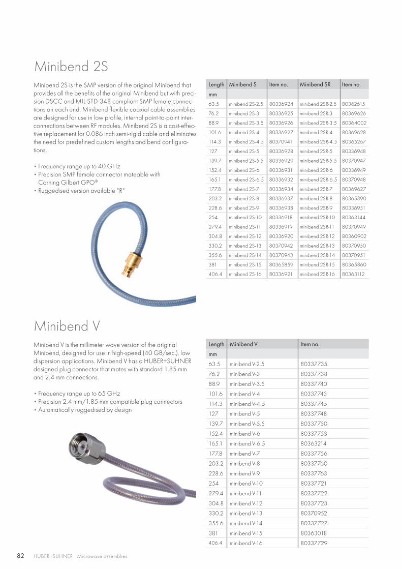
82 HUBER+SUHNER Microwave assemblies
Length Minibend S Item no. Minibend SR Item no.
mm
63.5 minibend 2S-2.5 80336924 minibend 2SR-2.5 80362615
76.2 minibend 2S-3 80336925 minibend 2SR-3 80369626
88.9 minibend 2S-3.5 80336926 minibend 2SR-3.5 80364002
101.6 minibend 2S-4 80336927 minibend 2SR-4 80369628
114.3 minibend 2S-4.5 80370941 minibend 2SR-4.5 80365267
127 minibend 2S-5 80336928 minibend 2SR-5 80336948
139.7 minibend 2S-5.5 80336929 minibend 2SR-5.5 80370947
152.4 minibend 2S-6 80336931 minibend 2SR-6 80336949
165.1 minibend 2S-6.5 80336932 minibend 2SR-6.5 80370948
177.8 minibend 2S-7 80336934 minibend 2SR-7 80369627
203.2 minibend 2S-8 80336937 minibend 2SR-8 80365390
228.6 minibend 2S-9 80336938 minibend 2SR-9 80336951
254 minibend 2S-10 80336918 minibend 2SR-10 80363144
279.4 minibend 2S-11 80336919 minibend 2SR-11 80370949
304.8 minibend 2S-12 80336920 minibend 2SR-12 80360902
330.2 minibend 2S-13 80370942 minibend 2SR-13 80370950
355.6 minibend 2S-14 80370943 minibend 2SR-14 80370951
381 minibend 2S-15 80365859 minibend 2SR-15 80365860
406.4 minibend 2S-16 80336921 minibend 2SR-16 80363112
Length Minibend V Item no.
mm
63.5 minibend V-2.5 80337735
76.2 minibend V-3 80337738
88.9 minibend V-3.5 80337740
101.6 minibend V-4 80337743
114.3 minibend V-4.5 80337745
127 minibend V-5 80337748
139.7 minibend V-5.5 80337750
152.4 minibend V-6 80337753
165.1 minibend V-6.5 80363214
177.8 minibend V-7 80337756
203.2 minibend V-8 80337760
228.6 minibend V-9 80337763
254 minibend V-10 80337721
279.4 minibend V-11 80337722
304.8 minibend V-12 80337723
330.2 minibend V-13 80370952
355.6 minibend V-14 80337727
381 minibend V-15 80363018
406.4 minibend V-16 80337729
Minibend 2SMinibend 2S is the SMP version of the original Minibend that provides all the benefits of the original Minibend but with preci-sion DSCC and MIL-STD-348 compliant SMP female connec-tions on each end. Minibend flexible coaxial cable assemblies are designed for use in low profile, internal point-to-point inter-connections between RF modules. Minibend 2S is a cost-effec-tive replacement for 0.086 inch semi-rigid cable and eliminates the need for predefined custom lengths and bend configura-tions.
• Frequency range up to 40 GHz • Precision SMP female connector mateable with
Corning Gilbert GPO®
• Ruggedised version available "R"
Minibend V is the millimeter wave version of the original Minibend, designed for use in high-speed (40 GB/sec.), low dispersion applications. Minibend V has a HUBER+SUHNER designed plug connector that mates with standard 1.85 mm and 2.4 mm connections.
• Frequency range up to 65 GHz • Precision 2.4 mm/1.85 mm compatible plug connectors • Automatically ruggedised by design
Minibend V
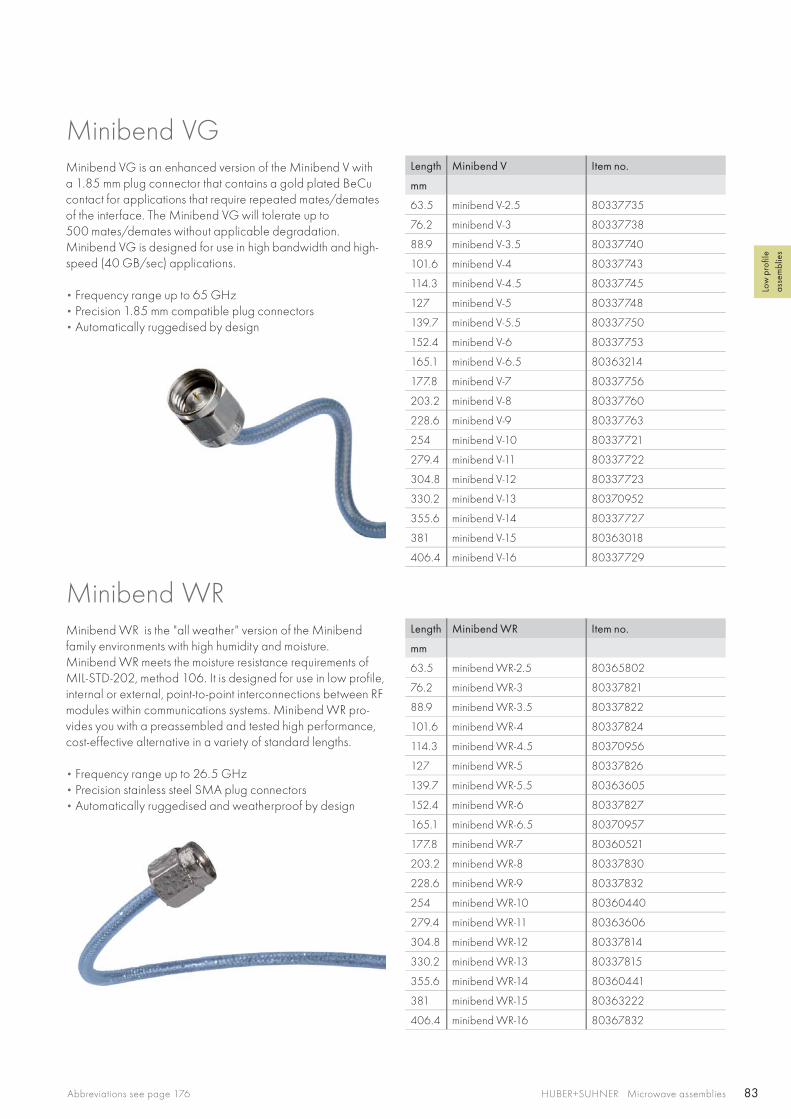
83HUBER+SUHNER Microwave assembliesAbbreviations see page 176
Low
pro
file
asse
mbl
ies
Length Minibend V Item no.
mm
63.5 minibend V-2.5 80337735
76.2 minibend V-3 80337738
88.9 minibend V-3.5 80337740
101.6 minibend V-4 80337743
114.3 minibend V-4.5 80337745
127 minibend V-5 80337748
139.7 minibend V-5.5 80337750
152.4 minibend V-6 80337753
165.1 minibend V-6.5 80363214
177.8 minibend V-7 80337756
203.2 minibend V-8 80337760
228.6 minibend V-9 80337763
254 minibend V-10 80337721
279.4 minibend V-11 80337722
304.8 minibend V-12 80337723
330.2 minibend V-13 80370952
355.6 minibend V-14 80337727
381 minibend V-15 80363018
406.4 minibend V-16 80337729
Length Minibend WR Item no.
mm
63.5 minibend WR-2.5 80365802
76.2 minibend WR-3 80337821
88.9 minibend WR-3.5 80337822
101.6 minibend WR-4 80337824
114.3 minibend WR-4.5 80370956
127 minibend WR-5 80337826
139.7 minibend WR-5.5 80363605
152.4 minibend WR-6 80337827
165.1 minibend WR-6.5 80370957
177.8 minibend WR-7 80360521
203.2 minibend WR-8 80337830
228.6 minibend WR-9 80337832
254 minibend WR-10 80360440
279.4 minibend WR-11 80363606
304.8 minibend WR-12 80337814
330.2 minibend WR-13 80337815
355.6 minibend WR-14 80360441
381 minibend WR-15 80363222
406.4 minibend WR-16 80367832
Minibend VGMinibend VG is an enhanced version of the Minibend V with a 1.85 mm plug connector that contains a gold plated BeCu contact for applications that require repeated mates/demates of the interface. The Minibend VG will tolerate up to 500 mates/demates without applicable degradation. Minibend VG is designed for use in high bandwidth and high-speed (40 GB/sec) applications.
• Frequency range up to 65 GHz• Precision 1.85 mm compatible plug connectors • Automatically ruggedised by design
Minibend WR is the "all weather" version of the Minibend family environments with high humidity and moisture. Minibend WR meets the moisture resistance requirements of MIL-STD-202, method 106. It is designed for use in low profile, internal or external, point-to-point interconnections between RF modules within communications systems. Minibend WR pro-vides you with a preassembled and tested high performance, cost-effective alternative in a variety of standard lengths.
• Frequency range up to 26.5 GHz • Precision stainless steel SMA plug connectors• Automatically ruggedised and weatherproof by design
Minibend WR
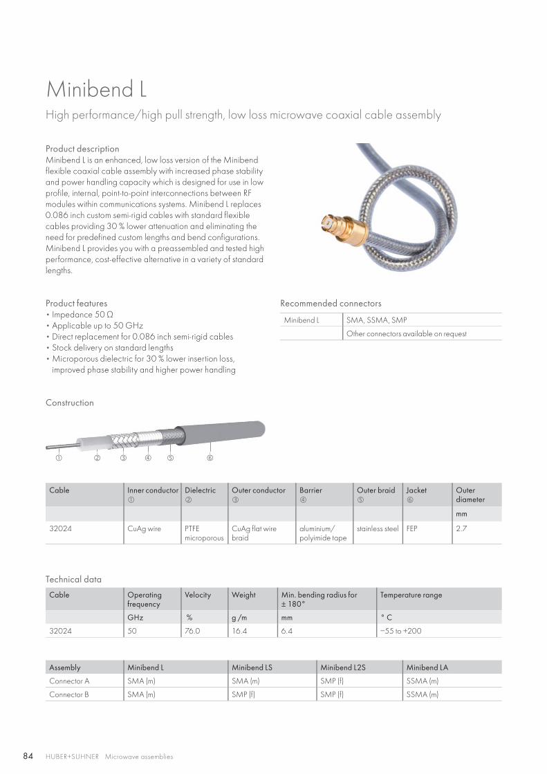
84
HUBER+SUHNER Microwave assemblies
Minibend LHigh performance/high pull strength, low loss microwave coaxial cable assembly
Product descriptionMinibend L is an enhanced, low loss version of the Minibend flexible coaxial cable assembly with increased phase stability and power handling capacity which is designed for use in low profile, internal, point-to-point interconnections between RF modules within communications systems. Minibend L replaces 0.086 inch custom semi-rigid cables with standard flexible cables providing 30 % lower attenuation and eliminating the need for predefined custom lengths and bend configurations. Minibend L provides you with a preassembled and tested high performance, cost-effective alternative in a variety of standard lengths.
Product features• Impedance 50 Ω • Applicable up to 50 GHz• Direct replacement for 0.086 inch semi-rigid cables• Stock delivery on standard lengths• Microporous dielectric for 30 % lower insertion loss,
improved phase stability and higher power handling
Construction
Recommended connectors
Minibend L SMA, SSMA, SMP
Other connectors available on request
Cable Inner conductor
Dielectric
Outer conductor
Barrier
Outer braid
Jacket
Outerdiameter
mm
32024 CuAg wire PTFE microporous
CuAg flat wire braid
aluminium/polyimide tape
stainless steel FEP 2.7
Assembly Minibend L Minibend LS Minibend L2S Minibend LA
Connector A SMA (m) SMA (m) SMP (f) SSMA (m)
Connector B SMA (m) SMP (f) SMP (f) SSMA (m)
Technical data
Cable Operating frequency
Velocity Weight Min. bending radius for± 180°
Temperature range
GHz % g /m mm ° C
32024 50 76.0 16.4 6.4 −55 to +200
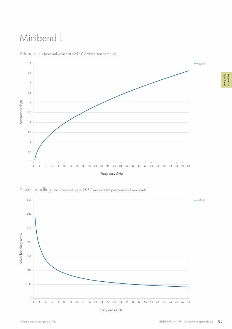
85
0 2 4 6 8 10 12 14 16 18 20 22 24 26 28 30 32 34 36 38 40 42 44 46 48 50
0 2 4 6 8 10 12 14 16 18 20 22 24 26 28 30 32 34 36 38 40 42 44 46 48 50
3
4
5
2
150
200
250
300
350
1
100
50
0
0.5
1.5
2.5
3.5
4.5
0
HUBER+SUHNER Microwave assembliesAbbreviations see page 176
Low
pro
file
asse
mbl
ies
Minibend LAttenuation (nominal values at +25 °C ambient temperature)
Power handling (maximum values at 25 °C ambient temperature and sea level)
Atte
nuat
ion
dB/m
Pow
er h
andl
ing
Wat
ts
Frequency GHz
Frequency GHz
32024
32024
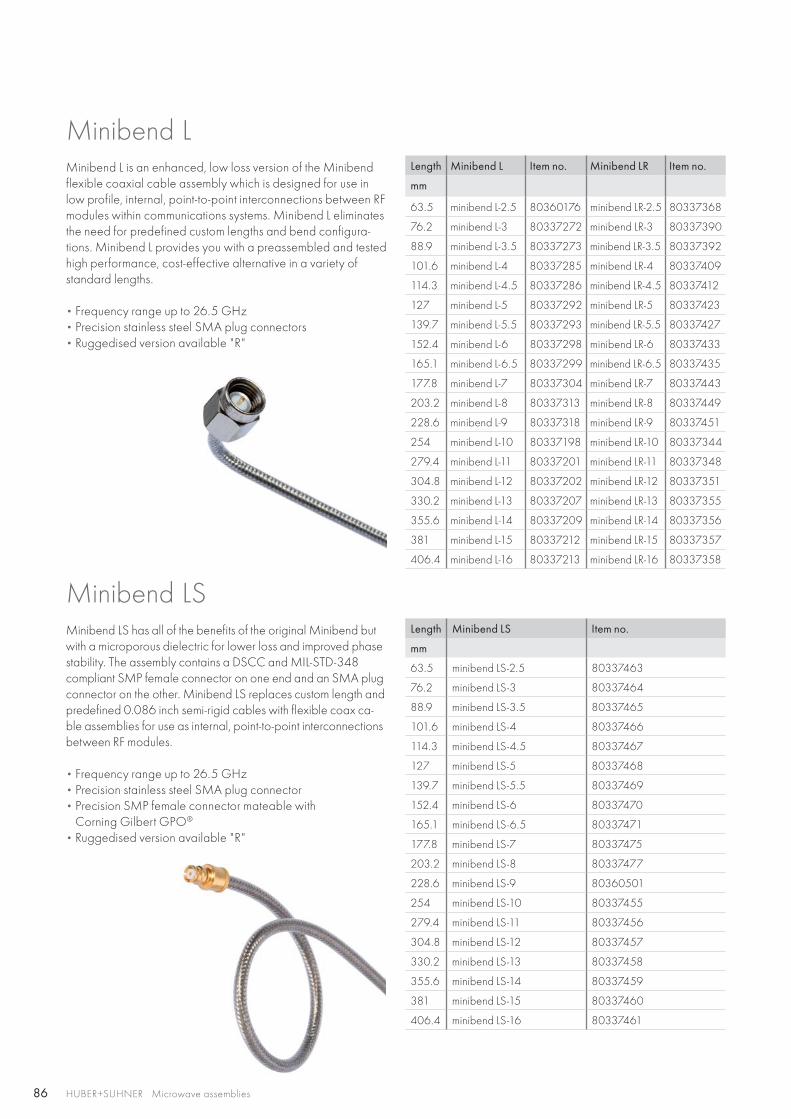
86 HUBER+SUHNER Microwave assemblies
Length Minibend L Item no. Minibend LR Item no.
mm
63.5 minibend L-2.5 80360176 minibend LR-2.5 80337368
76.2 minibend L-3 80337272 minibend LR-3 80337390
88.9 minibend L-3.5 80337273 minibend LR-3.5 80337392
101.6 minibend L-4 80337285 minibend LR-4 80337409
114.3 minibend L-4.5 80337286 minibend LR-4.5 80337412
127 minibend L-5 80337292 minibend LR-5 80337423
139.7 minibend L-5.5 80337293 minibend LR-5.5 80337427
152.4 minibend L-6 80337298 minibend LR-6 80337433
165.1 minibend L-6.5 80337299 minibend LR-6.5 80337435
177.8 minibend L-7 80337304 minibend LR-7 80337443
203.2 minibend L-8 80337313 minibend LR-8 80337449
228.6 minibend L-9 80337318 minibend LR-9 80337451
254 minibend L-10 80337198 minibend LR-10 80337344
279.4 minibend L-11 80337201 minibend LR-11 80337348
304.8 minibend L-12 80337202 minibend LR-12 80337351
330.2 minibend L-13 80337207 minibend LR-13 80337355
355.6 minibend L-14 80337209 minibend LR-14 80337356
381 minibend L-15 80337212 minibend LR-15 80337357
406.4 minibend L-16 80337213 minibend LR-16 80337358
Length Minibend LS Item no.
mm
63.5 minibend LS-2.5 80337463
76.2 minibend LS-3 80337464
88.9 minibend LS-3.5 80337465
101.6 minibend LS-4 80337466
114.3 minibend LS-4.5 80337467
127 minibend LS-5 80337468
139.7 minibend LS-5.5 80337469
152.4 minibend LS-6 80337470
165.1 minibend LS-6.5 80337471
177.8 minibend LS-7 80337475
203.2 minibend LS-8 80337477
228.6 minibend LS-9 80360501
254 minibend LS-10 80337455
279.4 minibend LS-11 80337456
304.8 minibend LS-12 80337457
330.2 minibend LS-13 80337458
355.6 minibend LS-14 80337459
381 minibend LS-15 80337460
406.4 minibend LS-16 80337461
Minibend L is an enhanced, low loss version of the Minibend flexible coaxial cable assembly which is designed for use in low profile, internal, point-to-point interconnections between RF modules within communications systems. Minibend L eliminates the need for predefined custom lengths and bend configura-tions. Minibend L provides you with a preassembled and tested high performance, cost-effective alternative in a variety of standard lengths.
• Frequency range up to 26.5 GHz • Precision stainless steel SMA plug connectors • Ruggedised version available "R"
Minibend LS has all of the benefits of the original Minibend but with a microporous dielectric for lower loss and improved phase stability. The assembly contains a DSCC and MIL-STD-348 compliant SMP female connector on one end and an SMA plug connector on the other. Minibend LS replaces custom length and predefined 0.086 inch semi-rigid cables with flexible coax ca-ble assemblies for use as internal, point-to-point interconnections between RF modules.
• Frequency range up to 26.5 GHz • Precision stainless steel SMA plug connector • Precision SMP female connector mateable with
Corning Gilbert GPO®
• Ruggedised version available "R"
Minibend LS
Minibend L

87HUBER+SUHNER Microwave assembliesAbbreviations see page 176
Low
pro
file
asse
mbl
ies
Length Minibend L2S Item no.
mm
63.5 minibend L2S-2.5 80337249
76.2 minibend L2S-3 80362626
88.9 minibend L2S-3.5 80367351
101.6 minibend L2S-4 80366004
114.3 minibend L2S-4.5 80337250
127 minibend L2S-5 80363891
139.7 minibend L2S-5.5 80337251
152.4 minibend L2S-6 80365111
165.1 minibend L2S-6.5 80367341
177.8 minibend L2S-7 80370924
203.2 minibend L2S-8 80366005
228.6 minibend L2S-9 80361796
254 minibend L2S-10 80362894
279.4 minibend L2S-11 80370911
304.8 minibend L2S-12 80365427
330.2 minibend L2S-13 80366870
355.6 minibend L2S-14 80366871
381 minibend L2S-15 80366872
406.4 minibend L2S-16 80337248
Length Minibend L2S Item no.
mm
63.5 minibend LA-2.5 80370912
76.2 minibend LA-3 80366857
88.9 minibend LA-3.5 80370913
101.6 minibend LA-4 80366135
114.3 minibend LA-4.5 80370914
127 minibend LA-5 80370915
139.7 minibend LA-5.5 80370916
152.4 minibend LA-6 80366858
165.1 minibend LA-6.5 80365398
177.8 minibend LA-7 80370917
203.2 minibend LA-8 80366622
228.6 minibend LA-9 80366841
254 minibend LA-10 80370918
279.4 minibend LA-11 80370919
304.8 minibend LA-12 80370920
330.2 minibend LA-13 80370921
355.6 minibend LA-14 80370922
381 minibend LA-15 80370923
406.4 minibend LA-16 80365399
Minibend L2S is the SMP female version of the original Minibend with a lower loss, microporous dielectric and DSCC and MIL-STD-348 compliant SMP female connectors on each end. Minibend L2S replaces custom length and bend configu-ration 0.086 inch semi-rigid cable with truly flexible coax ca-ble assemblies for use as internal interconnections between RF modules.
• Frequency range up to 40 GHz • Precision SMP female connector mateable with
Corning Gilbert GPO®
• Ruggedised version available "R"
Minibend LA is the SSMA plug version of the original Minibend with a microporous dielectric for lower loss and improved phase stability. Minibend LA replaces custom length and predefined bend configuration 0.086 inch semi-rigid cables with truly flexible coax cable assemblies for use as internal point-to-point interconnections between RF modules.
• Frequency range up to 40 GHz • Precision stainless steel SSMA plug connectors • Ruggedised version available "R"
Minibend LA
Minibend L2S
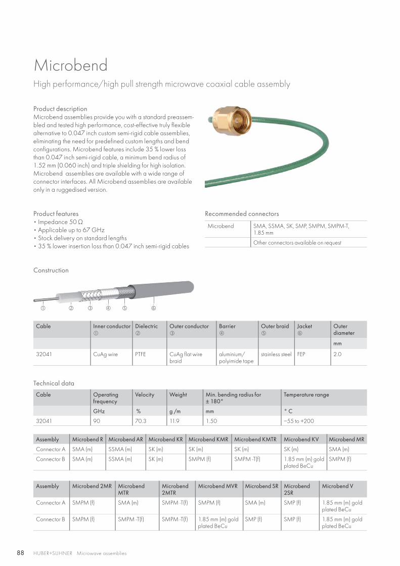
88
HUBER+SUHNER Microwave assemblies
Microbend High performance/high pull strength microwave coaxial cable assembly
Product descriptionMicrobend assemblies provide you with a standard preassem-bled and tested high performance, cost-effective truly flexible alternative to 0.047 inch custom semi-rigid cable assemblies, eliminating the need for predefined custom lengths and bend configurations. Microbend features include 35 % lower loss than 0.047 inch semi-rigid cable, a minimum bend radius of 1.52 mm (0.060 inch) and triple shielding for high isolation. Microbend assemblies are available with a wide range of connector interfaces. All Microbend assemblies are available only in a ruggedised version.
Product features• Impedance 50 Ω • Applicable up to 67 GHz• Stock delivery on standard lengths• 35 % lower insertion loss than 0.047 inch semi-rigid cables
Construction
Recommended connectors
Microbend SMA, SSMA, SK, SMP, SMPM, SMPM-T,1.85 mm
Other connectors available on request
Cable Inner conductor
Dielectric
Outer conductor
Barrier
Outer braid
Jacket
Outerdiameter
mm
32041 CuAg wire PTFE CuAg flat wire braid
aluminium/polyimide tape
stainless steel FEP 2.0
Assembly Microbend R Microbend AR Microbend KR Microbend KMR Microbend KMTR Microbend KV Microbend MR
Connector A SMA (m) SSMA (m) SK (m) SK (m) SK (m) SK (m) SMA (m)
Connector B SMA (m) SSMA (m) SK (m) SMPM (f) SMPM -T(f) 1.85 mm (m) gold plated BeCu
SMPM (f)
Technical data
Cable Operating frequency
Velocity Weight Min. bending radius for± 180°
Temperature range
GHz % g /m mm ° C
32041 90 70.3 11.9 1.50 −55 to +200
Assembly Microbend 2MR Microbend MTR
Microbend2MTR
Microbend MVR Microbend SR Microbend 2SR
Microbend V
Connector A SMPM (f) SMA (m) SMPM -T(f) SMPM (f) SMA (m) SMP (f) 1.85 mm (m) gold plated BeCu
Connector B SMPM (f) SMPM -T(f) SMPM -T(f) 1.85 mm (m) gold plated BeCu
SMP (f) SMP (f) 1.85 mm (m) gold plated BeCu

89
0 2 4 6 8 10 12 14 16 18 20 22 24 26 28 30 32 34 36 38 40 42 44 46 48 50 52 54 56 58 60 62 64 66 68 70 72 74 76 78 80 82 84 86 88 90
0 2 4 6 8 10 12 14 16 18 20 22 24 26 28 30 32 34 36 38 40 42 44 46 48 50 52 54 56 58 60 62 64 66 68 70 72 74 76 78 80 82 84 86 88 90
6
10
12
14
8
4
120
2
100
20
40
60
80
0
0
HUBER+SUHNER Microwave assembliesAbbreviations see page 176
Low
pro
file
asse
mbl
ies
MicrobendAttenuation (nominal values at +25 °C ambient temperature)
Power handling (maximum values at 25 °C ambient temperature and sea level)
Atte
nuat
ion
dB/m
Pow
er h
andl
ing
Wat
ts
Frequency GHz
Frequency GHz
32041
32041

90 HUBER+SUHNER Microwave assemblies
Lengt Microbend R Item no.
mm
63.5 microbend R-2.5 80336652
76.2 microbend R-3 80336654
88.9 microbend R-3.5 80336655
101.6 microbend R-4 80336658
114.3 microbend R-4.5 80336659
127 microbend R-5 80336662
139.7 microbend R-5.5 80336664
152.4 microbend R-6 80336665
165.1 microbend R-6.5 80363961
177.8 microbend R-7 80336667
203.2 microbend R-8 80336668
228.6 microbend R-9 80336669
254 microbend R-10 80336646
279.4 microbend R-11 80336648
304.8 microbend R-12 80336649
Length Microbend AR Item no.
mm
63.5 microbend AR-2.5 80370830
76.2 microbend AR-3 80370831
88.9 microbend AR-3.5 80370832
101.6 microbend AR-4 80336531
114.3 microbend AR-4.5 80370833
127 microbend AR-5 80363838
139.7 microbend AR-5.5 80370834
152.4 microbend AR-6 80336532
165.1 microbend AR-6.5 80370835
177.8 microbend AR-7 80370836
203.2 microbend AR-8 80336533
228.6 microbend AR-9 80370837
254 microbend AR-10 80336529
279.4 microbend AR-11 80370838
304.8 microbend AR-12 80362731
Microbend RMicrobend R eliminates the need for predefined custom lengths and bend configurations. Microbend R was designed for use as internal point-to-point interconnections between modules in microwave and fiber optic switching systems. Microbend R features include lower loss than 0.047 inch semi-rigid cable and a minimum bend radius of 1.52 mm (0.060 inch).
• Frequency range up to 26.5 GHz • Precision stainless steel SMA plug connectors • Automatically ruggedised by design
Microbend ARMicrobend AR is the SSMA plug version of the of the Micro-bend. Microbend AR replaces custom length, predefined bend configuration 0.047 inch semi-rigid cable with truly flexible coax cable in standard lengths.
• Frequency range up to 40 GHz • Precision stainless steel SSMA plug connectors • Automatically ruggedised by design
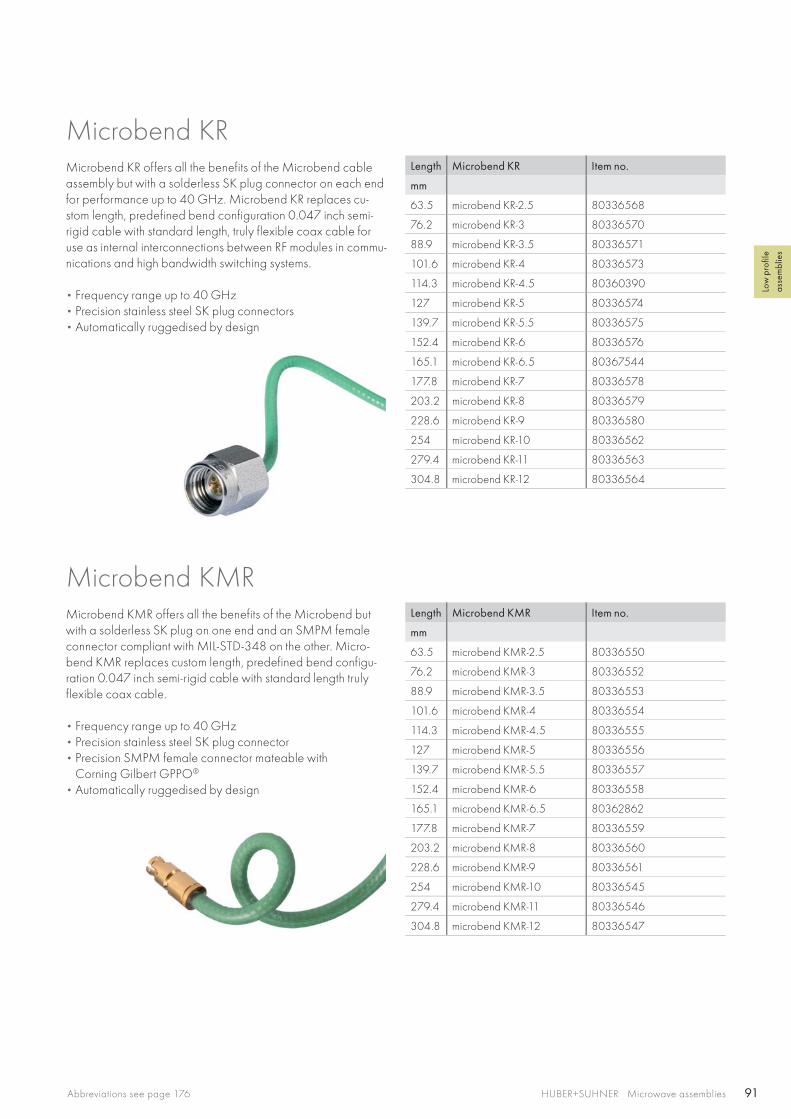
91HUBER+SUHNER Microwave assembliesAbbreviations see page 176
Low
pro
file
asse
mbl
ies
Length Microbend KR Item no.
mm
63.5 microbend KR-2.5 80336568
76.2 microbend KR-3 80336570
88.9 microbend KR-3.5 80336571
101.6 microbend KR-4 80336573
114.3 microbend KR-4.5 80360390
127 microbend KR-5 80336574
139.7 microbend KR-5.5 80336575
152.4 microbend KR-6 80336576
165.1 microbend KR-6.5 80367544
177.8 microbend KR-7 80336578
203.2 microbend KR-8 80336579
228.6 microbend KR-9 80336580
254 microbend KR-10 80336562
279.4 microbend KR-11 80336563
304.8 microbend KR-12 80336564
Length Microbend KMR Item no.
mm
63.5 microbend KMR-2.5 80336550
76.2 microbend KMR-3 80336552
88.9 microbend KMR-3.5 80336553
101.6 microbend KMR-4 80336554
114.3 microbend KMR-4.5 80336555
127 microbend KMR-5 80336556
139.7 microbend KMR-5.5 80336557
152.4 microbend KMR-6 80336558
165.1 microbend KMR-6.5 80362862
177.8 microbend KMR-7 80336559
203.2 microbend KMR-8 80336560
228.6 microbend KMR-9 80336561
254 microbend KMR-10 80336545
279.4 microbend KMR-11 80336546
304.8 microbend KMR-12 80336547
Microbend KR offers all the benefits of the Microbend cable assembly but with a solderless SK plug connector on each end for performance up to 40 GHz. Microbend KR replaces cu-stom length, predefined bend configuration 0.047 inch semi-rigid cable with standard length, truly flexible coax cable for use as internal interconnections between RF modules in commu-nications and high bandwidth switching systems.
• Frequency range up to 40 GHz • Precision stainless steel SK plug connectors • Automatically ruggedised by design
Microbend KR
Microbend KMR offers all the benefits of the Microbend but with a solderless SK plug on one end and an SMPM female connector compliant with MIL-STD-348 on the other. Micro-bend KMR replaces custom length, predefined bend configu-ration 0.047 inch semi-rigid cable with standard length truly flexible coax cable.
• Frequency range up to 40 GHz • Precision stainless steel SK plug connector • Precision SMPM female connector mateable with
Corning Gilbert GPPO®
• Automatically ruggedised by design
Microbend KMR
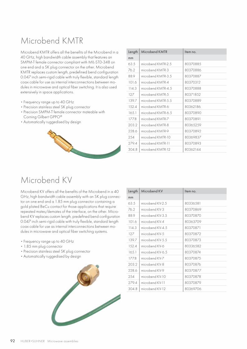
92 HUBER+SUHNER Microwave assemblies
Length Microbend KMTR Item no.
mm
63.5 microbend KMTR-2.5 80370885
76.2 microbend KMTR-3 80370886
88.9 microbend KMTR-3.5 80370887
101.6 microbend KMTR-4 80370312
114.3 microbend KMTR-4.5 80370888
127 microbend KMTR-5 80371852
139.7 microbend KMTR-5.5 80370889
152.4 microbend KMTR-6 80362186
165.1 microbend KMTR-6.5 80370890
177.8 microbend KMTR-7 80370891
203.2 microbend KMTR-8 80365259
228.6 microbend KMTR-9 80370892
254 microbend KMTR-10 80369837
279.4 microbend KMTR-11 80370893
304.8 microbend KMTR-12 80362144
Length Microbend KV Item no.
mm
63.5 microbend KV-2.5 80336581
76.2 microbend KV-3 80370869
88.9 microbend KV-3.5 80370870
101.6 microbend KV-4 80363709
114.3 microbend KV-4.5 80370871
127 microbend KV-5 80370872
139.7 microbend KV-5.5 80370873
152.4 microbend KV-6 80336582
165.1 microbend KV-6.5 80370874
177.8 microbend KV-7 80370875
203.2 microbend KV-8 80370876
228.6 microbend KV-9 80370877
254 microbend KV-10 80370878
279.4 microbend KV-11 80370879
304.8 microbend KV-12 80369706
Microbend KMTRMicrobend KMTR offers all the benefits of the Microbend in a 40 GHz, high bandwidth cable assembly that features an SMPM-T female connector compliant with MIL-STD-348 on one end and a SK plug connector on the other. Microbend KMTR replaces custom length, predefined bend configuration 0.047 inch semi-rigid cable with truly flexible, standard length coax cable for use as internal interconnections between mo-dules in microwave and optical fiber switching. It is also used extensively in space applications.
• Frequency range up to 40 GHz • Precision stainless steel SK plug connector • Precision SMPM-T female connector mateable with
Corning Gilbert GPPO®
• Automatically ruggedised by design
Microbend KVMicrobend KV offers all the benefits of the Microbend in a 40 GHz, high bandwidth cable assembly with an SK plug connec-tor on one end and a 1.85 mm plug connector containing a gold plated BeCu contact for those applications that require repeated mates/demates of the interface, on the other. Micro-bend KV replaces custom length, predefined bend configuration 0.047 inch semi-rigid cable with truly flexible, standard length coax cable for use as internal interconnections between mo-dules in microwave and optical fiber switching systems.
• Frequency range up to 40 GHz • 1.85 mm plug connector • Precision stainless steel SK plug connector• Automatically ruggedised by design
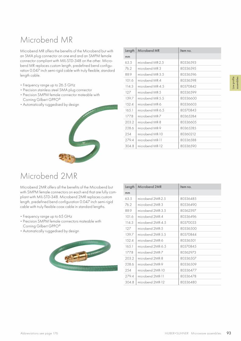
93HUBER+SUHNER Microwave assembliesAbbreviations see page 176
Low
pro
file
asse
mbl
ies
Length Microbend MR Item no.
mm
63.5 microbend MR-2.5 80336593
76.2 microbend MR-3 80336595
88.9 microbend MR-3.5 80336596
101.6 microbend MR-4 80336598
114.3 microbend MR-4.5 80370842
127 microbend MR-5 80336599
139.7 microbend MR-5.5 80336600
152.4 microbend MR-6 80336603
165.1 microbend MR-6.5 80370843
177.8 microbend MR-7 80365284
203.2 microbend MR-8 80336605
228.6 microbend MR-9 80365285
254 microbend MR-10 80360212
279.4 microbend MR-11 80336588
304.8 microbend MR-12 80336590
Length Microbend 2MR Item no.
mm
63.5 microbend 2MR-2.5 80336485
76.2 microbend 2MR-3 80336490
88.9 microbend 2MR-3.5 80362597
101.6 microbend 2MR-4 80336496
114.3 microbend 2MR-4.5 80370033
127 microbend 2MR-5 80336500
139.7 microbend 2MR-5.5 80370844
152.4 microbend 2MR-6 80336501
165.1 microbend 2MR-6.5 80370845
177.8 microbend 2MR-7 80362973
203.2 microbend 2MR-8 80336507
228.6 microbend 2MR-9 80336509
254 microbend 2MR-10 80336477
279.4 microbend 2MR-11 80336478
304.8 microbend 2MR-12 80336480
Microbend MRMicrobend MR offers the benefits of the Microbend but with an SMA plug connector on one end and an SMPM female connector compliant with MIL-STD-348 on the other. Micro-bend MR replaces custom length, predefined bend configu-ration 0.047 inch semi-rigid cable with truly flexible, standard length cable.
• Frequency range up to 26.5 GHz • Precision stainless steel SMA plug connector • Precision SMPM female connector mateable with
Corning Gilbert GPPO® • Automatically ruggedised by design
Microbend 2MR offers all the benefits of the Microbend but with SMPM female connectors on each end that are fully com-pliant with MIL-STD-348. Microbend 2MR replaces custom length, predefined bend configuration 0.047 inch semi-rigid cable with truly flexible coax cable in standard lengths.
• Frequency range up to 65 GHz • Precision SMPM female connectors mateable with
Corning Gilbert GPPO®
• Automatically ruggedised by design
Microbend 2MR

94 HUBER+SUHNER Microwave assemblies
Length Microbend MTR Item no.
mm
63.5 microbend MTR-2.5 80370846
76.2 microbend MTR-3 80371995
88.9 microbend MTR-3.5 80370847
101.6 microbend MTR-4 80366736
114.3 microbend MTR-4.5 80370848
127 microbend MTR-5 80366725
139.7 microbend MTR-5.5 80370849
152.4 microbend MTR-6 80361103
165.1 microbend MTR-6.5 80370850
177.8 microbend MTR-7 80366726
203.2 microbend MTR-8 80396610
228.6 microbend MTR-9 80362047
254 microbend MTR-10 80366737
279.4 microbend MTR-11 80370851
304.8 microbend MTR-12 80362145
Length Microbend 2MTR Item no.
mm
63.5 microbend 2MTR-2.5 80370855
76.2 microbend 2MTR-3 80366641
88.9 microbend 2MTR-3.5 80367802
101.6 microbend 2MTR-4 80370856
114.3 microbend 2MTR-4.5 80366674
127 microbend 2MTR-5 80367803
139.7 microbend 2MTR-5.5 80370857
152.4 microbend 2MTR-6 80365945
165.1 microbend 2MTR-6.5 80370858
177.8 microbend 2MTR-7 80367804
203.2 microbend 2MTR-8 80360654
228.6 microbend 2MTR-9 80367805
254 microbend 2MTR-10 80367172
279.4 microbend 2MTR-11 80370859
304.8 microbend 2MTR-12 80362560
Microbend MTRMicrobend MTR offers all the benefits of the Microbend in a 26.5 GHz, high bandwidth cable assembly that features an SMPM-T female connector compliant with MIL-STD-348 on one end and a SMA plug connector on the other. Microbend MTR replaces custom length, predefined bend configuration 0.047 inch semi-rigid cable with truly flexible, standard length coax cable for use as internal interconnections between mo-dules in microwave and optical fiber switching. It is also used extensively in space applications.
• Frequency range up to 26.5 GHz • Precision stainless steel SMA plug connector• Precision SMPM-T female connector mateable with
Corning Gilbert GPPO®
• Automatically ruggedised by design
Microbend 2MTRMicrobend 2MTR offers all the benefits of the Microbend MTR in a 40 GHz, high bandwidth cable assembly that features an SMPM-T female connector compliant with MIL-STD-348 on each side. Microbend 2MTR replaces custom length, prede-fined bend configuration 0.047 inch semi-rigid cable with truly flexible, standard length coax cable for use as internal intercon-nections between modules in microwave and optical fiber switching. It is also used extensively in space applications.
• Frequency range up to 65 GHz • Precision SMPM-T female connectors mateable with
Corning Gilbert GPPO®
• Automatically ruggedised by design

95HUBER+SUHNER Microwave assembliesAbbreviations see page 176
Low
pro
file
asse
mbl
ies
Length Microbend MVR Item no.
mm
63.5 microbend MVR-2.5 80336620
76.2 microbend MVR-3 80336623
88.9 microbend MVR-3.5 80336626
101.6 microbend MVR-4 80336633
114.3 microbend MVR-4.5 80370862
127 microbend MVR-5 80336638
139.7 microbend MVR-5.5 80370863
152.4 microbend MVR-6 80336640
165.1 microbend MVR-6.5 80370864
177.8 microbend MVR-7 80336641
203.2 microbend MVR-8 80336643
228.6 microbend MVR-9 80336645
254 microbend MVR-10 80336613
279.4 microbend MVR-11 80370865
304.8 microbend MVR-12 80336614
Length Microbend SR Item no.
mm
63.5 microbend SR-2.5 80336674
76.2 microbend SR-3 80366686
88.9 microbend SR-3.5 80336676
101.6 microbend SR-4 80336677
114.3 microbend SR-4.5 80363639
127 microbend SR-5 80336679
139.7 microbend SR-5.5 80363701
152.4 microbend SR-6 80336681
165.1 microbend SR-6.5 80366676
177.8 microbend SR-7 80336684
203.2 microbend SR-8 80336685
228.6 microbend SR-9 80336686
254 microbend SR-10 80370899
279.4 microbend SR-11 80370900
304.8 microbend SR-12 80336671
Microbend MVR offers all the benefits of the Microbend in a 65 GHz, high bandwidth cable assembly that features an SMPM female connector compliant with MIL-STD-348 on one end and a 1.85 mm plug connector containing a gold plated BeCu contact for those applications that require repeated mates/demates of the interface on the other. Microbend MVR replaces custom length, predefined bend configuration 0.047 inch semi-rigid cable with truly flexible, standard length coax cable for use as internal interconnections between modules in microwave and optical fiber switching systems.
• Frequency range up to 65 GHz • 1.85 mm plug connector • Precision SMPM female connector mateable with
Corning Gilbert GPPO®
• Automatically ruggedised by design
Microbend MVR
Microbend SR offers the benefits of the standard Microbend with an SMA plug connector on one end and a DSCC and MIL-STD-348 compliant SMP female connector on the other. Microbend SR replaces custom length, predefined bend confi-guration 0.047 inch semi-rigid cable with truly flexible, cost-effective, standard length coax cables for use as internal inter-connections between RF modules of communications systems.
• Frequency range up to 26.5 GHz • Precision stainless steel SMA plug connector • Precision SMP female connector mateable with
Corning Gilbert GPO®
• Automatically ruggedised by design
Microbend SR
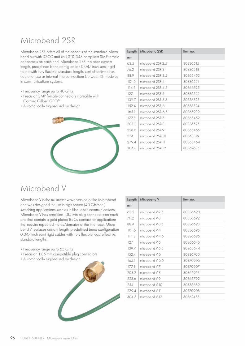
96 HUBER+SUHNER Microwave assemblies
Length Microbend 2SR Item no.
mm
63.5 microbend 2SR-2.5 80336515
76.2 microbend 2SR-3 80336518
88.9 microbend 2SR-3.5 80365453
101.6 microbend 2SR-4 80336521
114.3 microbend 2SR-4.5 80366525
127 microbend 2SR-5 80336522
139.7 microbend 2SR-5.5 80336523
152.4 microbend 2SR-6 80336524
165.1 microbend 2SR-6.5 80365939
177.8 microbend 2SR-7 80365452
203.2 microbend 2SR-8 80336525
228.6 microbend 2SR-9 80365455
254 microbend 2SR-10 80363819
279.4 microbend 2SR-11 80365454
304.8 microbend 2SR-12 80362685
Length Microbend V Item no.
mm
63.5 microbend V-2.5 80336690
76.2 microbend V-3 80336692
88.9 microbend V-3.5 80336693
101.6 microbend V-4 80336695
114.3 microbend V-4.5 80336696
127 microbend V-5 80366545
139.7 microbend V-5.5 80365644
152.4 microbend V-6 80336700
165.1 microbend V-6.5 80370906
177.8 microbend V-7 80370907
203.2 microbend V-8 80366953
228.6 microbend V-9 80365792
254 microbend V-10 80336689
279.4 microbend V-11 80370908
304.8 microbend V-12 80362488
Microbend 2SR offers all of the benefits of the standard Micro-bend but with DSCC and MIL-STD-348 compliant SMP female connectors on each end. Microbend 2SR replaces custom length, predefined bend configuration 0.047 inch semi-rigid cable with truly flexible, standard length, cost-effective coax cable for use as internal interconnections between RF modules in communications systems.
• Frequency range up to 40 GHz • Precision SMP female connectors mateable with
Corning Gilbert GPO®
• Automatically ruggedised by design
Microbend 2SR
Microbend VMicrobend V is the millimeter wave version of the Microbend and was designed for use in high-speed (40 Gb/sec.) switching applications such as in fiber optic communications. Microbend V has precision 1.85 mm plug connectors on each end that contain a gold plated BeCu contact for applications that require repeated mates/demates of the interface. Micro-bend V replaces custom length, predefined bend configuration 0.047 inch semi-rigid cables with truly flexible, cost-effective, standard lengths.
• Frequency range up to 65 GHz • Precision 1.85 mm compatible plug connectors • Automatically ruggedised by design
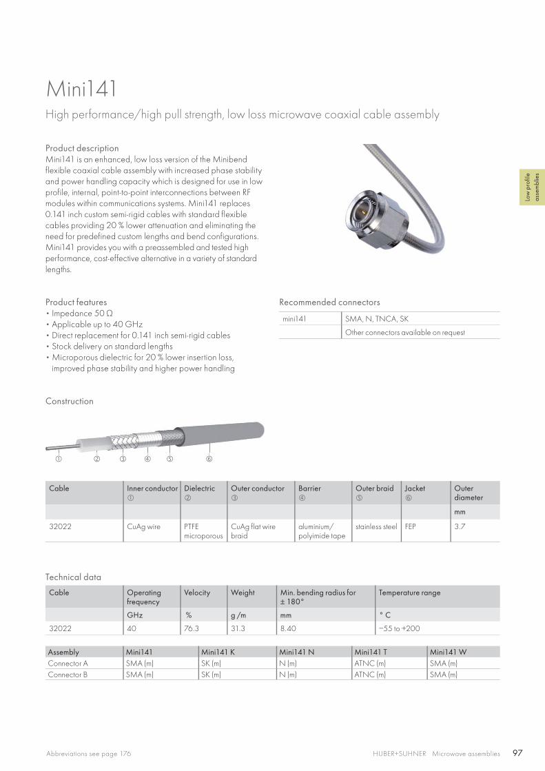
97
HUBER+SUHNER Microwave assembliesAbbreviations see page 176
Low
pro
file
asse
mbl
ies
Mini141 High performance/high pull strength, low loss microwave coaxial cable assembly
Product descriptionMini141 is an enhanced, low loss version of the Minibend flexible coaxial cable assembly with increased phase stability and power handling capacity which is designed for use in low profile, internal, point-to-point interconnections between RF modules within communications systems. Mini141 replaces 0.141 inch custom semi-rigid cables with standard flexible cables providing 20 % lower attenuation and eliminating the need for predefined custom lengths and bend configurations. Mini141 provides you with a preassembled and tested high performance, cost-effective alternative in a variety of standard lengths.
Product features• Impedance 50 Ω • Applicable up to 40 GHz• Direct replacement for 0.141 inch semi-rigid cables• Stock delivery on standard lengths• Microporous dielectric for 20 % lower insertion loss,
improved phase stability and higher power handling
Construction
Cable Inner conductor
Dielectric
Outer conductor
Barrier
Outer braid
Jacket
Outerdiameter
mm
32022 CuAg wire PTFEmicroporous
CuAg flat wire braid
aluminium/polyimide tape
stainless steel FEP 3.7
Recommended connectors
mini141 SMA, N, TNCA, SK
Other connectors available on request
Assembly Mini141 Mini141 K Mini141 N Mini141 T Mini141 WConnector A SMA (m) SK (m) N (m) ATNC (m) SMA (m)Connector B SMA (m) SK (m) N (m) ATNC (m) SMA (m)
Technical data
Cable Operating frequency
Velocity Weight Min. bending radius for± 180°
Temperature range
GHz % g /m mm ° C
32022 40 76.3 31.3 8.40 −55 to +200
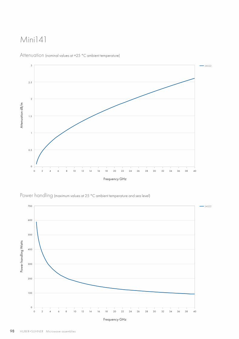
98
0 2 4 6 8 10 12 14 16 18 20 22 24 26 28 30 32 34 36 38 40
0 2 4 6 8 10 12 14 16 18 20 22 24 26 28 30 32 34 36 38 40
3
2.5
2
1.5
200
300
400
500
600
700
1
100
0.5
0
0
HUBER+SUHNER Microwave assemblies
Mini141
Attenuation (nominal values at +25 °C ambient temperature)
Power handling (maximum values at 25 °C ambient temperature and sea level)
Atte
nuat
ion
dB/m
Pow
er h
andl
ing
Wat
ts
Frequency GHz
Frequency GHz
34022
34022
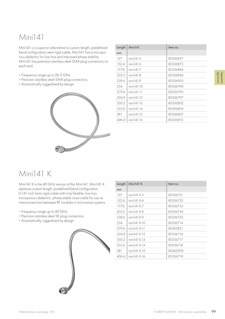
99HUBER+SUHNER Microwave assembliesAbbreviations see page 176
Low
pro
file
asse
mbl
ies
Length Mini141 Item no.
mm
127 mini141-5 80336857
152.4 mini141-6 80336872
177.8 mini141-7 80336884
203.2 mini141-8 80336896
228.6 mini141-9 80336905
254 mini141-10 80336790
279.4 mini141-11 80336793
304.8 mini141-12 80336797
330.2 mini141-13 80336802
355.6 mini141-14 80336804
381 mini141-15 80336807
406.4 mini141-16 80336810
Length Mini141 K Item no.
mm
127 mini141 K-5 80336731
152.4 mini141 K-6 80336732
177.8 mini141 K-7 80336733
203.2 mini141 K-8 80336734
228.6 mini141 K-9 80336735
254 mini141 K-10 80336714
279.4 mini141 K-11 80362851
304.8 mini141 K-12 80336716
330.2 mini141 K-13 80336717
355.6 mini141 K-14 80336718
381 mini141 K-15 80362909
406.4 mini141 K-16 80336719
Mini141Mini141 is a superior alternative to custom length, predefined bend configuration semi-rigid cable. Mini141 has a micropo-rous dielectric for low loss and improved phase stability. Mini141 has precision stainless steel SMA plug connectors on each end.
• Frequency range up to 26.5 GHz • Precision stainless steel SMA plug connectors • Automatically ruggedised by design
Mini141 KMini141 K is the 40 GHz version of the Mini141. Mini141 K replaces custom length, predefined bend configuration 0.141 inch Semi-rigid cable with truly flexible, low loss microporous dielectric, phase stable coax cable for use as interconnections between RF modules in microwave systems.
• Frequency range up to 40 GHz • Precision stainless steel SK plug connectors • Automatically ruggedised by design

100 HUBER+SUHNER Microwave assemblies
Length Mini141 N Item no.
mm
127 mini141 N-5 80336745
152.4 mini141 N-6 80336747
177.8 mini141 N-7 80365109
203.2 mini141 N-8 80336748
228.6 mini141 N-9 80366643
254 mini141 N-10 80363841
279.4 mini141 N-11 80362163
304.8 mini141 N-12 80336736
330.2 mini141 N-13 80366110
355.6 mini141 N-14 80336737
381 mini141 N-15 80361505
406.4 mini141 N-16 80336738
Length Mini141 T Item no.
mm
127 mini141 T-5 80336751
152.4 mini141 T-6 80336752
177.8 mini141 T-7 80366192
203.2 mini141 T-8 80336753
228.6 mini141 T-9 80336912
254 mini141 T-10 80363433
279.4 mini141 T-11 80370800
304.8 mini141 T-12 80336911
330.2 mini141 T-13 80366954
355.6 mini141 T-14 80370801
381 mini141 T-15 80370802
406.4 mini141 T-16 80365426
Mini141 N offers all of the features and benefits of the Mini141 but with N plug connections. Mini141 N replaces custom length, predefined bend configuration 0.141 inch semi-rigid cable with truly flexible, low loss, phase stable microporous dielectric coax cable in standard lengths.
• Frequency range up to 18 GHz • Precision stainless steel N plug connectors • Automatically ruggedised by design
Mini141 N
Mini141 T offers all of the features and benefits of the Mini141 but with ATNC plug connections. Mini141 T replaces custom length, predefined bend configuration 0.141 inch semi-rigid cable with truly flexible, low loss, phase stable microporous dielectric coax cable in standard lengths.
• Frequency range up to 18.5 GHz • Precision stainless steel ATNC plug connectors compatible
with TNC or TNC-A connectors per MIL-STD-348• Automatically ruggedised by design
Mini141 T
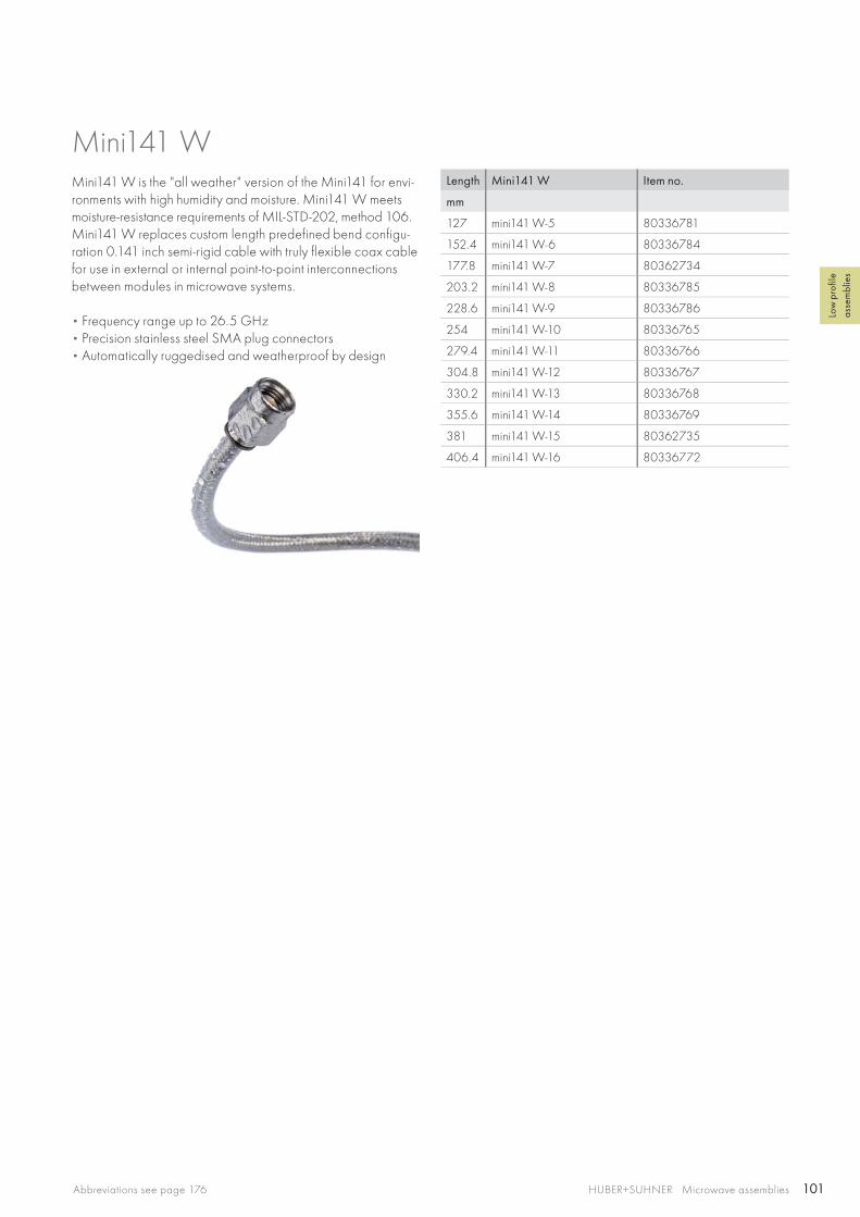
101HUBER+SUHNER Microwave assembliesAbbreviations see page 176
Low
pro
file
asse
mbl
ies
Length Mini141 W Item no.
mm
127 mini141 W-5 80336781
152.4 mini141 W-6 80336784
177.8 mini141 W-7 80362734
203.2 mini141 W-8 80336785
228.6 mini141 W-9 80336786
254 mini141 W-10 80336765
279.4 mini141 W-11 80336766
304.8 mini141 W-12 80336767
330.2 mini141 W-13 80336768
355.6 mini141 W-14 80336769
381 mini141 W-15 80362735
406.4 mini141 W-16 80336772
Mini141 WMini141 W is the "all weather" version of the Mini141 for envi-ronments with high humidity and moisture. Mini141 W meets moisture-resistance requirements of MIL-STD-202, method 106. Mini141 W replaces custom length predefined bend configu-ration 0.141 inch semi-rigid cable with truly flexible coax cable for use in external or internal point-to-point interconnections between modules in microwave systems.
• Frequency range up to 26.5 GHz • Precision stainless steel SMA plug connectors • Automatically ruggedised and weatherproof by design

102 HUBER+SUHNER Microwave assemblies
Test leads for Test+Measurement set-upsThe best measurement set-up is only as good as its weakest link. To obtain reliable and reproduce-able measurement results, particular care must be taken in selecting the components required for the measurement set-up.
HUBER+SUHNER's extensive range of high quality test leads are matched to the various needs in the field of test and measurement. All these products are distinguished by their high performance and stable characteristics – the result of years of experience in the development and production of radio frequency components.

103HUBER+SUHNER Microwave assembliesAbbreviations see page 176
Test
asse
mbl
ies
Sucotest 26/Sucotest 40 page 104
The test lead up to 26/40 GHz
Sucotest 18A page 107
The test lead for harsh environment up to 18 GHz –precision at a constant high level
Sucotest 18 page 110
The test lead up to 18 GHz –for the highest standard of measurement
TL-8A page 112
The test lead for component and equipment testing up to 8 GHz
TL-P page 114
High flexible test lead for passive intermodulation (PIM) andreturn loss for frequency up to 4 GHz
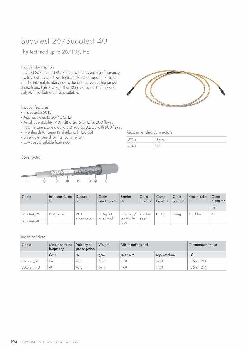
104
HUBER+SUHNER Microwave assemblies
Technical data
Cable Max. operating frequency
Velocity of propagation
Weight Min. bending radii Temperature range
GHz % g/m static mm repeated mm °C
Sucotest_26 26 76.3 62.5 17.8 53.3 −55 to +200
Sucotest_40 40 76.3 62.5 17.8 53.3 −55 to +200
Construction
Cable Inner conductor
Dielectric
Outerconductor
Barrier
Outerbraid
Outerbraid
Outerbraid
Outer jacket
Outerdiameter
mm
Sucotest_26 CuAg wire PTFE microporous
CuAg flat wire braid
aluminum/polyimide tape
stainless steel
CuAg CuAg FEP, blue 4.8
Sucotest_40
Recommended connectors
ST26 SMA
ST40 SK
Product descriptionSucotest 26/Sucotest 40 cable assemblies are high frequency, low loss cables which are triple shielded for superior RF isolati-on. The internal stainless steel outer braid provides higher pull strength and lighter weight than RG style cable. Nomex and polyolefin jackets are also available.
Sucotest 26/Sucotest 40The test lead up to 26/40 GHz
Product features• Impedance 50 Ω• Applicable up to 26/40 GHz• Amplitude stability: < 0.1 dB at 26.5 GHz for 200 flexes
180° in one plane around a 2“ radius, 0.2 dB with 600 flexes• Five shields for super RF shielding (−120 dB)• Steel outer shield for high pull strength• Low cost, available from stock
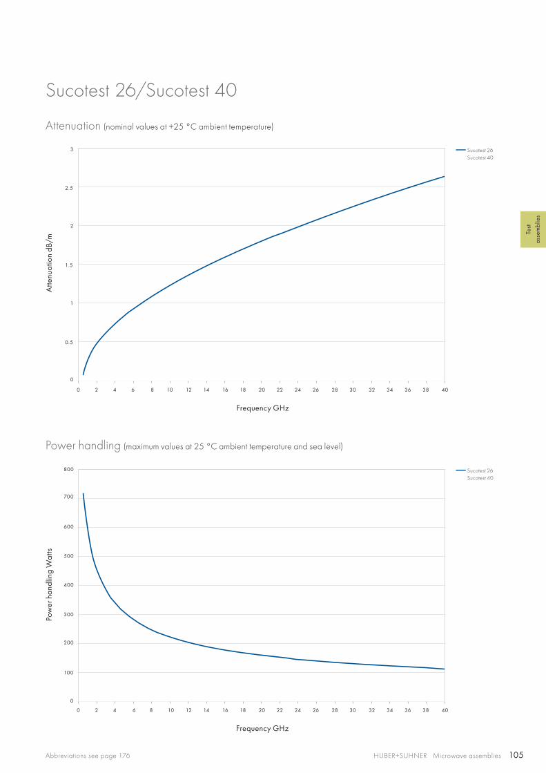
105
0 2 4 6 8 10 12 14 16 18 20 22 24 26 28 30 32 34 36 38 40
0 2 4 6 8 10 12 14 16 18 20 22 24 26 28 30 32 34 36 38 40
3
2.5
2
1.5
200
300
400
500
600
700
800
1
100
0.5
0
0
Sucotest 26Sucotest 40
Sucotest 26Sucotest 40
HUBER+SUHNER Microwave assembliesAbbreviations see page 176
Test
asse
mbl
ies
Sucotest 26/Sucotest 40
Attenuation (nominal values at +25 °C ambient temperature)
Power handling (maximum values at 25 °C ambient temperature and sea level)
Atte
nuat
ion
dB/m
Pow
er h
andl
ing
Wat
ts
Frequency GHz
Frequency GHz
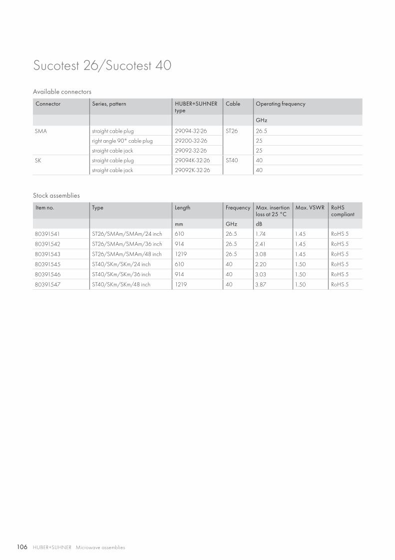
106 HUBER+SUHNER Microwave assemblies
Available connectors
Connector Series, pattern HUBER+SUHNER type
Cable Operating frequency
GHz
SMA straight cable plug 29094-32-26 ST26 26.5
right angle 90° cable plug 29200-32-26 25
straight cable jack 29092-32-26 25
SK straight cable plug 29094K-32-26 ST40 40
straight cable jack 29092K-32-26 40
Stock assemblies
Item no. Type Length Frequency Max. insertion loss at 25 °C
Max. VSWR RoHScompliant
mm GHz dB
80391541 ST26/SMAm/SMAm/24 inch 610 26.5 1.74 1.45 RoHS 5
80391542 ST26/SMAm/SMAm/36 inch 914 26.5 2.41 1.45 RoHS 5
80391543 ST26/SMAm/SMAm/48 inch 1219 26.5 3.08 1.45 RoHS 5
80391545 ST40/SKm/SKm/24 inch 610 40 2.20 1.50 RoHS 5
80391546 ST40/SKm/SKm/36 inch 914 40 3.03 1.50 RoHS 5
80391547 ST40/SKm/SKm/48 inch 1219 40 3.87 1.50 RoHS 5
Sucotest 26/Sucotest 40

107
HUBER+SUHNER Microwave assembliesAbbreviations see page 176
Test
asse
mbl
ies
Product descriptionSucotest 18A armoured test assemblies offer excellent electri-cal performance (low insertion loss combined with unique stability and excellent return loss) for heavy duty, outdoor and harsh environment measurements up to 18 GHz.Sucotest 18A armoured test assemblies are ideal for testing wireless communication infrastructures, defense and ground systems and in daily use in components and assembly shops.
Product features• Impedance 50 Ω • Applicable up to 18 GHz• High flexibility in spite of armouring• Phase and loss stability with flexure• Crush-, torque- and kink-resistant• Waterproof IP68
Recommended connectors
ST_18A N, 7/16
Construction
Cable Inner conductor
Dielectric
Outer conductor
Jacket
Ruggedisation
Outer diameter
mm
Sucotest_18A CuAg strand LD-PTFE CuAg tape/braid FEP stainless steel/PUR, blue
10.3
Available connectors
Connector Series, pattern HUBER+SUHNER type
Cable Operatingfrequency
VSWR per connector
GHz
7/16 straight cable plug 11_716-403 ST_18A 7.5 1.14
straight cable jack 21_716-403 7.5 1.14
N straight cable plug 11_N-468 18 1.14
straight cable jack 21_N-409 18 1.14
Sucotest 18AThe test lead for harsh environment up to 18 GHz – precision at a constant high level
Technical data
Cable Operating frequency
Velocity ofpropagation
Weight Min. bending radius for± 180°
Temperature range
GHz % g /m mm °C
Sucotest_18A 18 77 175.0 50.0 −40 to +85
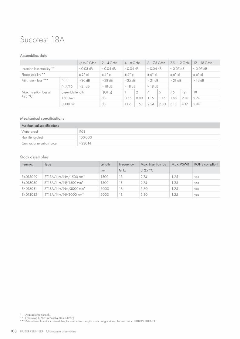
108 HUBER+SUHNER Microwave assemblies
Stock assemblies
Item no. Type Length Frequency Max. insertion los Max. VSWR ROHS compliant
mm GHz at 25 °C
84013029 ST18A/Nm/Nm/1500 mm* 1500 18 2.74 1.25 yes
84013030 ST18A/Nm/Nf/1500 mm* 1500 18 2.74 1.25 yes
84013031 ST18A/Nm/Nm/3000 mm* 3000 18 5.30 1.25 yes
84013032 ST18A/Nm/Nf/3000 mm* 3000 18 5.30 1.25 yes
Mechanical specifications
Mechanical specifications
Waterproof IP68
Flex life (cycles) 100 000
Connector retention force > 230 N
Assemblies data
up to 2 GHz 2 – 4 GHz 4 – 6 GHz 6 – 7.5 GHz 7.5 – 12 GHz 12 – 18 GHz
Insertion loss stability ** < 0.03 dB < 0.04 dB < 0.04 dB < 0.04 dB < 0.05 dB < 0.05 dB
Phase stability ** ± 2° el ± 4° el ± 4° el ± 6° el ± 6° el ± 6° el
Min. return loss *** N-N > 30 dB > 28 dB > 25 dB > 21 dB > 21 dB > 19 dB
N-7/16 > 21 dB > 18 dB > 18 dB > 18 dB
Max. insertion loss at+25 °C
assembly length f (GHz) 1 2 4 6 7.5 12 18
1500 mm dB 0.55 0.80 1.16 1.45 1.65 2.16 2.74
3000 mm dB 1.06 1.53 2.24 2.80 3.18 4.17 5.30
Sucotest 18A
* Available from stock.** One wrap (360°) around a 50 mm (2.0“) *** Return loss of on stock assemblies, for customised lengths and configurations please contact HUBER+SUHNER.
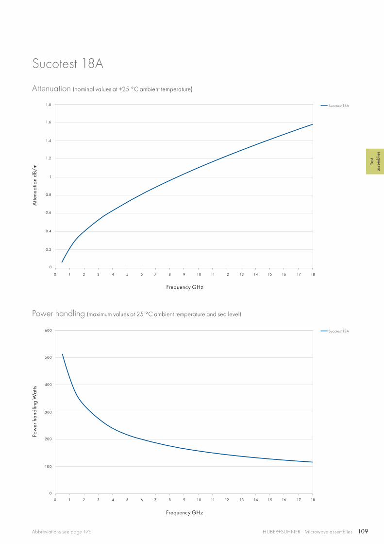
109
0 1 2 3 4 5 6 7 8 9 10 11 12 13 14 15 16 17 18
0 1 2 3 4 5 6 7 8 9 10 11 12 13 14 15 16 17 18
1.2
1.4
1.6
1.8
1
0.4
0.6
0.8
200
300
400
500
600
100
0.2
0
0
Sucotest 18A
Sucotest 18A
HUBER+SUHNER Microwave assembliesAbbreviations see page 176
Test
asse
mbl
ies
Sucotest 18A
Attenuation (nominal values at +25 °C ambient temperature)
Power handling (maximum values at 25 °C ambient temperature and sea level)
Atte
nuat
ion
dB/m
Pow
er h
andl
ing
Wat
ts
Frequency GHz
Frequency GHz
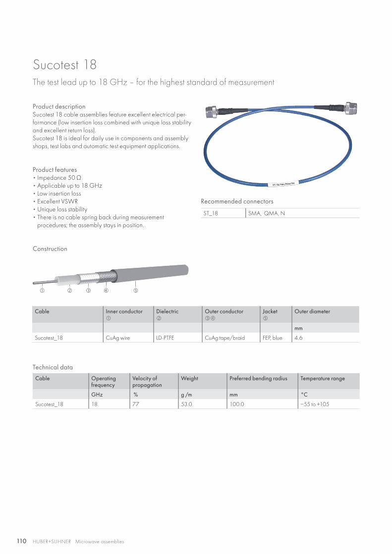
110
HUBER+SUHNER Microwave assemblies
Product descriptionSucotest 18 cable assemblies feature excellent electrical per-formance (low insertion loss combined with unique loss stability and excellent return loss).Sucotest 18 is ideal for daily use in components and assembly shops, test labs and automatic test equipment applications.
Product features• Impedance 50 Ω • Applicable up to 18 GHz• Low insertion loss• Excellent VSWR• Unique loss stability• There is no cable spring back during measurement
procedures; the assembly stays in position.
Recommended connectors
ST_18 SMA, QMA, N
Construction
Cable Inner conductor
Dielectric
Outer conductor
Jacket
Outer diameter
mm
Sucotest_18 CuAg wire LD-PTFE CuAg tape/braid FEP, blue 4.6
Sucotest 18The test lead up to 18 GHz – for the highest standard of measurement
Technical data
Cable Operating frequency
Velocity ofpropagation
Weight Preferred bending radius Temperature range
GHz % g /m mm °C
Sucotest_18 18 77 53.0 100.0 −55 to +105

111HUBER+SUHNER Microwave assembliesAbbreviations see page 176
Test
asse
mbl
ies
Sucotest 18
Specifications
Frequency range 2 GHz 2.01 – 4 GHz 4.01 – 6 GHz 6.01 – 12 GHz 12.01 – 18 GHz
Power handling 25 °C, sea level (W) > 391 > 277 > 225 > 160 > 131
Return loss (dB) > 30 >28 > 25 > 21 > 19
Insertion loss stability vs. shaking (dB) < 0.03 < 0.03 < 0.03 < 0.03 < 0.03
Insertion loss stability vs. bending (dB) < 0.03 < 0.04 < 0.04 < 0.05 < 0.05
Insertion loss stability vs. torsion (dB) < 0.03 < 0.04 < 0.04 < 0.05 < 0.05
HUBER+SUHNERcable type
Item no. Assembly length(ref. – ref. )mm/in
Weightgram
Insertion loss dB
up to2 GHz
2.01 –4 GHz
4.01 –6 GHz
6.01 – 12 GHz
12.01 – 18 GHz
ST-18/SMAm/SMAm/36 inch 84002061 914/36 68 < 0.48 < 0.68 < 0.84 < 1.21 < 1.51
ST-18/Nm/Nm/36 inch 84002060 914/36 110 < 0.48 < 0.68 < 0.84 < 1.21 < 1.51
ST-18/SMAm/Nm/36 inch 84004594 914/36 90 < 0.48 < 0.68 < 0.84 < 1.21 < 1.51
ST-18/SMAm/SMAm/48 inch 84003373 1219/48 80 < 0.61 < 0.88 < 1.09 < 1.57 < 1.95
ST-18/Nm/Nm/48 inch 84003372 1219/48 122 < 0.61 < 0.88 < 1.09 < 1.57 < 1.95
ST-18/SMAm/Nm/48 inch 84004006 1219/48 101 < 0.61 < 0.88 < 1.09 < 1.57 < 1.95
ST-18/SMAm/SMAm/72 inch 84004007 1829/72 108 < 0.89 < 1.28 < 1.58 < 2.29 < 2.85
ST-18/Nm/Nm/72 inch 84004070 1829/72 157 < 0.89 < 1.28 < 1.58 < 2.29 < 2.85
ST-18/SMAm/Nm/72 inch 84004595 1829/72 134 < 0.89 < 1.28 < 1.58 < 2.29 < 2.85
Other lengths on request with minimum order quantity of 50 pcs.
Stock assemblies
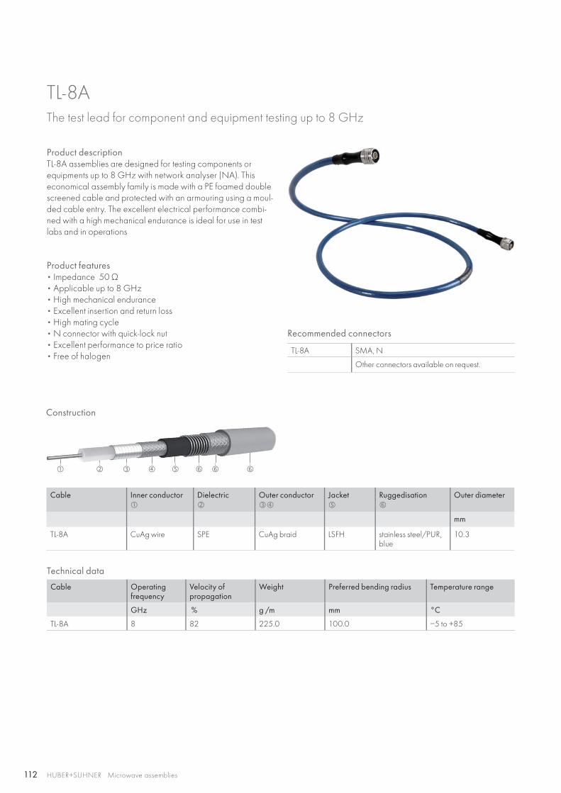
112
HUBER+SUHNER Microwave assemblies
Product descriptionTL-8A assemblies are designed for testing components or equipments up to 8 GHz with network analyser (NA). This economical assembly family is made with a PE foamed double screened cable and protected with an armouring using a moul-ded cable entry. The excellent electrical performance combi-ned with a high mechanical endurance is ideal for use in test labs and in operations
Product features• Impedance 50 Ω• Applicable up to 8 GHz• High mechanical endurance • Excellent insertion and return loss • High mating cycle• N connector with quick-lock nut• Excellent performance to price ratio • Free of halogen
Recommended connectors
TL-8A SMA, N
Other connectors available on request.
Construction
Cable Inner conductor
Dielectric
Outer conductor
Jacket
Ruggedisation
Outer diameter
mm
TL-8A CuAg wire SPE CuAg braid LSFH stainless steel/PUR, blue
10.3
TL-8AThe test lead for component and equipment testing up to 8 GHz
Technical data
Cable Operating frequency
Velocity ofpropagation
Weight Preferred bending radius Temperature range
GHz % g /m mm °C
TL-8A 8 82 225.0 100.0 −5 to +85
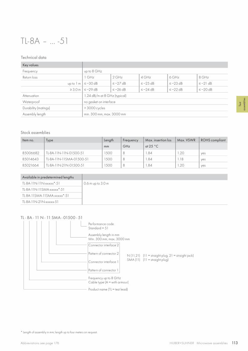
113HUBER+SUHNER Microwave assembliesAbbreviations see page 176
Test
asse
mbl
ies
Stock assemblies
Item no. Type Length Frequency Max. insertion los Max. VSWR ROHS compliant
mm GHz at 25 °C
85006682 TL-8A-11N-11N-01500-51 1500 8 1.84 1.20 yes
85014643 TL-8A-11N-11SMA-01500-51 1500 8 1.84 1.18 yes
85021664 TL-8A-11N-21N-01500-51 1500 8 1.84 1.20 yes
TL-8A – ... -51
Technical data
Key values
Frequency up to 8 GHz
Return loss 1 GHz 2 GHz 4 GHz 6 GHz 8 GHz
up to 1 m ≤ −30 dB ≤ −27 dB ≤ −25 dB ≤ −23 dB ≤ −21 dB
≥ 3.0 m ≤ −29 dB ≤ −26 dB ≤ −24 dB ≤ −22 dB ≤ −20 dB
Attenuation 1.24 dB/m at 8 GHz (typical)
Waterproof no gasket on interface
Durability (matings) > 3000 cycles
Assembly length min. 300 mm, max. 3000 mm
TL - 8A - 11 N - 11 SMA - 01500 - 51Performance codeStandard = 51
Assembly length in mmMin. 300 mm, max. 3000 mm
Frequency up to 8 GHzCable type (A = with armour)
Product name (TL = test lead)
Connector interface 2
Pattern of connector 2
Connector interface 1
Pattern of connector 1
N (11,21)SMA (11)
* Length of assembly in mm; length up to four meters on request.
Available in predetermined lengths
TL-8A-11N-11N-xxxxx*-51 0.6 m up to 3.0 m
TL-8A-11N-11SMA-xxxxx*-51
TL-8A-11SMA-11SMA-xxxxx*-51
TL-8A-11N-21N-xxxxx-51
(11 = straight plug, 21 = straight jack)(11 = straight plug)
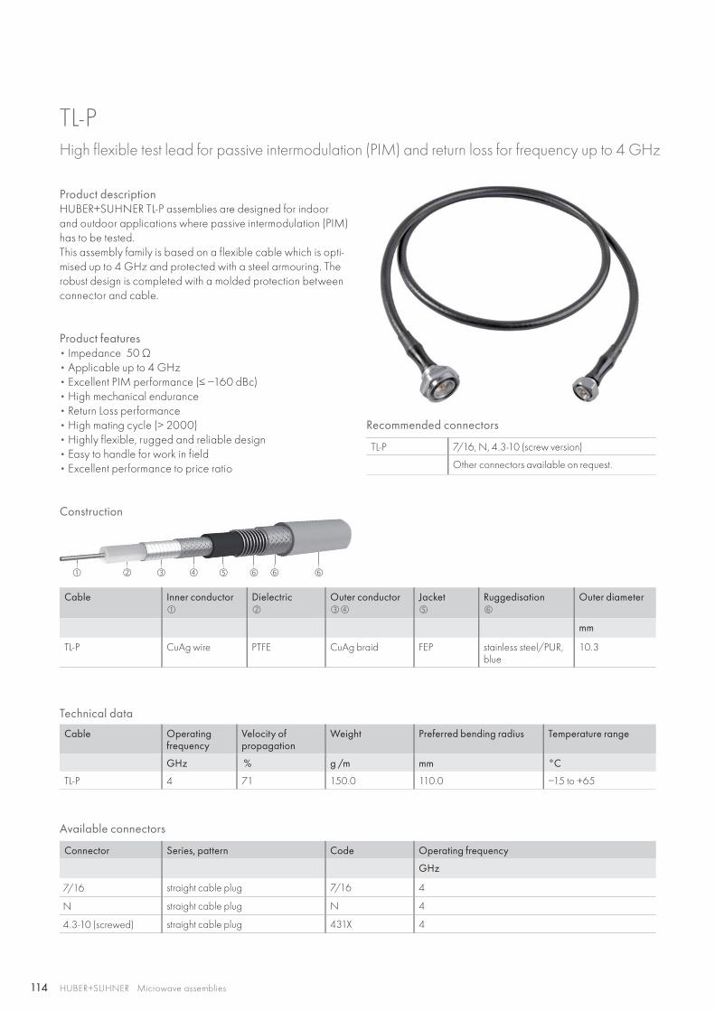
114
HUBER+SUHNER Microwave assemblies
Product descriptionHUBER+SUHNER TL-P assemblies are designed for indoor and outdoor applications where passive intermodulation (PIM) has to be tested.This assembly family is based on a flexible cable which is opti-mised up to 4 GHz and protected with a steel armouring. The robust design is completed with a molded protection between connector and cable.
Product features• Impedance 50 Ω• Applicable up to 4 GHz• Excellent PIM performance (≤ −160 dBc)• High mechanical endurance• Return Loss performance• High mating cycle (> 2000)• Highly flexible, rugged and reliable design• Easy to handle for work in field• Excellent performance to price ratio
Recommended connectors
TL-P 7/16, N, 4.3-10 (screw version)
Other connectors available on request.
Construction
Cable Inner conductor
Dielectric
Outer conductor
Jacket
Ruggedisation
Outer diameter
mm
TL-P CuAg wire PTFE CuAg braid FEP stainless steel/PUR, blue
10.3
Available connectors
Connector Series, pattern Code Operating frequency
GHz
7/16 straight cable plug 7/16 4
N straight cable plug N 4
4.3-10 (screwed) straight cable plug 431X 4
TL-PHigh flexible test lead for passive intermodulation (PIM) and return loss for frequency up to 4 GHz
Technical data
Cable Operating frequency
Velocity ofpropagation
Weight Preferred bending radius Temperature range
GHz % g /m mm °C
TL-P 4 71 150.0 110.0 −15 to +65
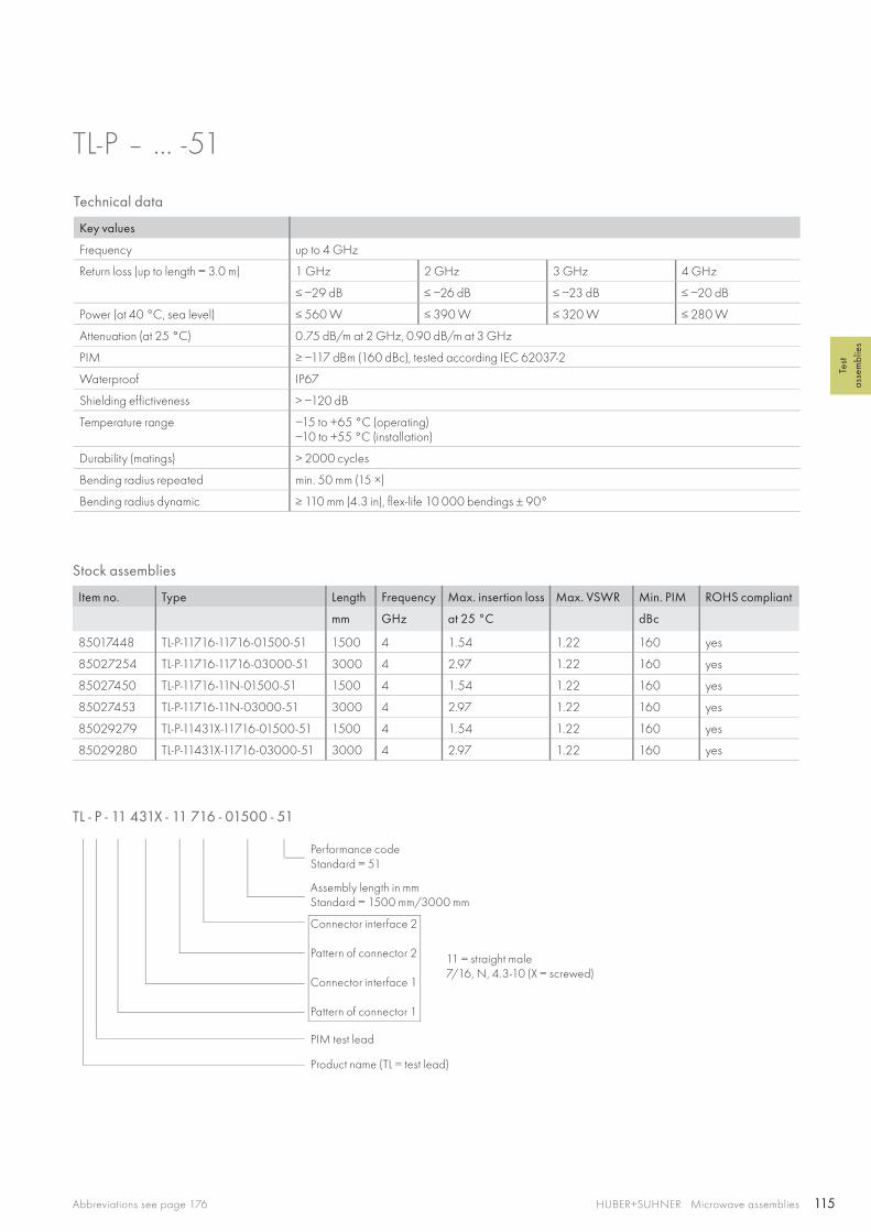
115HUBER+SUHNER Microwave assembliesAbbreviations see page 176
Test
asse
mbl
ies
Stock assemblies
Item no. Type Length Frequency Max. insertion loss Max. VSWR Min. PIM ROHS compliant
mm GHz at 25 °C dBc
85017448 TL-P-11716-11716-01500-51 1500 4 1.54 1.22 160 yes
85027254 TL-P-11716-11716-03000-51 3000 4 2.97 1.22 160 yes
85027450 TL-P-11716-11N-01500-51 1500 4 1.54 1.22 160 yes
85027453 TL-P-11716-11N-03000-51 3000 4 2.97 1.22 160 yes
85029279 TL-P-11431X-11716-01500-51 1500 4 1.54 1.22 160 yes
85029280 TL-P-11431X-11716-03000-51 3000 4 2.97 1.22 160 yes
TL-P – ... -51
Technical data
Key values
Frequency up to 4 GHz
Return loss (up to length = 3.0 m) 1 GHz 2 GHz 3 GHz 4 GHz
≤ −29 dB ≤ −26 dB ≤ −23 dB ≤ −20 dB
Power (at 40 °C, sea level) ≤ 560 W ≤ 390 W ≤ 320 W ≤ 280 W
Attenuation (at 25 °C) 0.75 dB/m at 2 GHz, 0.90 dB/m at 3 GHz
PIM ≥ −117 dBm (160 dBc), tested according IEC 62037-2
Waterproof IP67
Shielding effictiveness > −120 dB
Temperature range −15 to +65 °C (operating)−10 to +55 °C (installation)
Durability (matings) > 2000 cycles
Bending radius repeated min. 50 mm (15 ×)
Bending radius dynamic ≥ 110 mm (4.3 in), flex-life 10 000 bendings ± 90°
TL - P - 11 431X - 11 716 - 01500 - 51
Performance codeStandard = 51
Assembly length in mmStandard = 1500 mm/3000 mm
PIM test lead
Product name (TL = test lead)
Connector interface 2
Pattern of connector 2
Connector interface 1
Pattern of connector 1
11 = straight male 7/16, N, 4.3-10 (X = screwed)
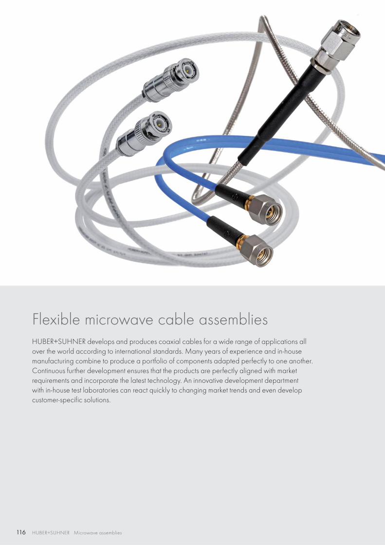
116 HUBER+SUHNER Microwave assemblies
Flexible microwave cable assemblies HUBER+SUHNER develops and produces coaxial cables for a wide range of applications all over the world according to international standards. Many years of experience and in-house manufacturing combine to produce a portfolio of components adapted perfectly to one another. Continuous further development ensures that the products are perfectly aligned with market requirements and incorporate the latest technology. An innovative development department with in-house test laboratories can react quickly to changing market trends and even develop customer-specific solutions.
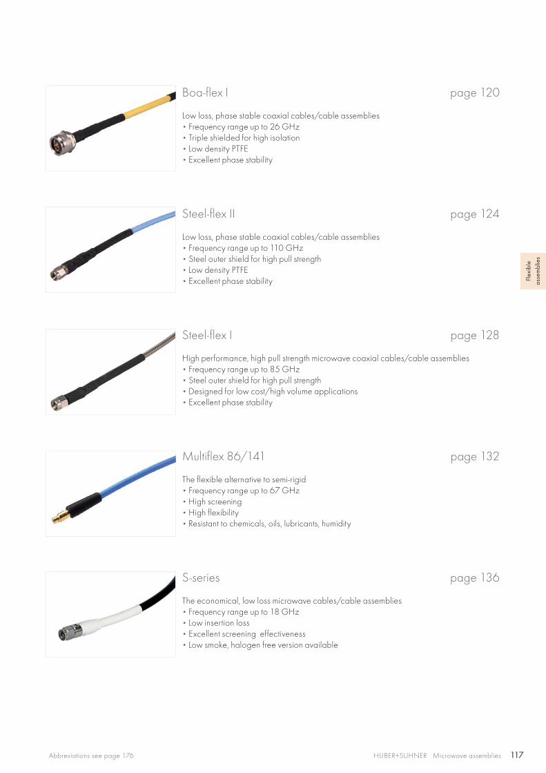
117HUBER+SUHNER Microwave assembliesAbbreviations see page 176
Flex
ible
as
sem
blie
s
Steel-flex I page 128
High performance, high pull strength microwave coaxial cables/cable assemblies• Frequency range up to 85 GHz • Steel outer shield for high pull strength• Designed for low cost/high volume applications• Excellent phase stability
Multiflex 86/141 page 132
The flexible alternative to semi-rigid• Frequency range up to 67 GHz • High screening• High flexibility• Resistant to chemicals, oils, lubricants, humidity
S-series page 136
The economical, low loss microwave cables/cable assemblies• Frequency range up to 18 GHz • Low insertion loss• Excellent screening effectiveness• Low smoke, halogen free version available
Steel-flex II page 124
Low loss, phase stable coaxial cables/cable assemblies• Frequency range up to 110 GHz • Steel outer shield for high pull strength• Low density PTFE • Excellent phase stability
Boa-flex I page 120
Low loss, phase stable coaxial cables/cable assemblies• Frequency range up to 26 GHz • Triple shielded for high isolation• Low density PTFE • Excellent phase stability
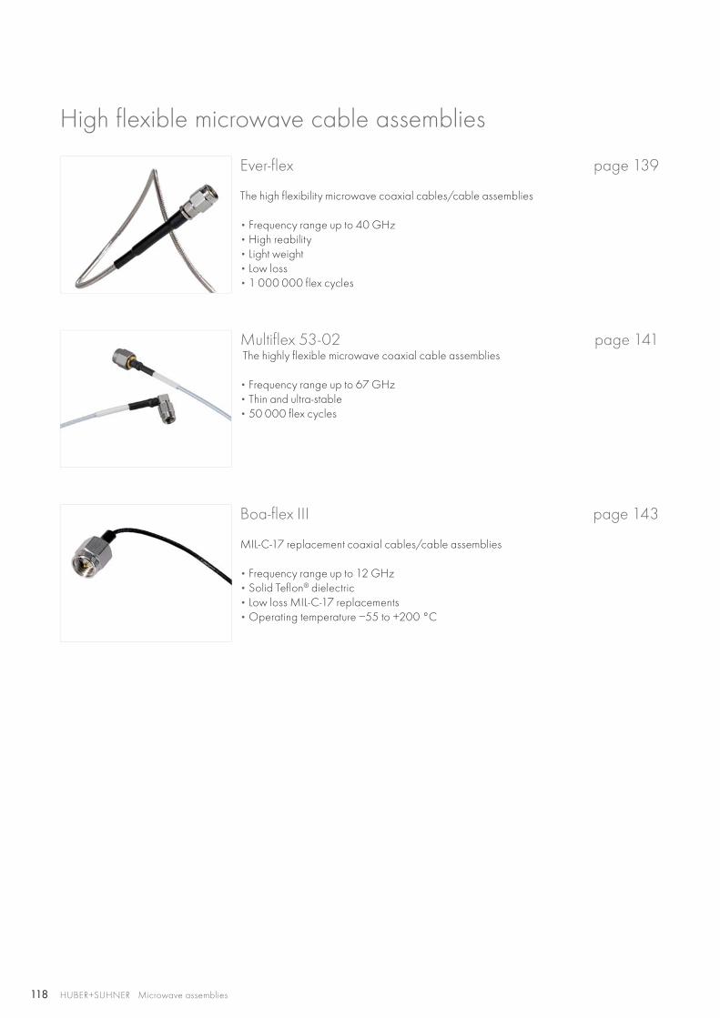
118 HUBER+SUHNER Microwave assemblies
High flexible microwave cable assemblies
Multiflex 53-02 page 141 The highly flexible microwave coaxial cable assemblies
• Frequency range up to 67 GHz • Thin and ultra-stable• 50 000 flex cycles
Boa-flex III page 143
MIL-C-17 replacement coaxial cables/cable assemblies
• Frequency range up to 12 GHz • Solid Teflon® dielectric• Low loss MIL-C-17 replacements• Operating temperature −55 to +200 °C
Ever-flex page 139
The high flexibility microwave coaxial cables/cable assemblies
• Frequency range up to 40 GHz • High reability• Light weight• Low loss• 1 000 000 flex cycles
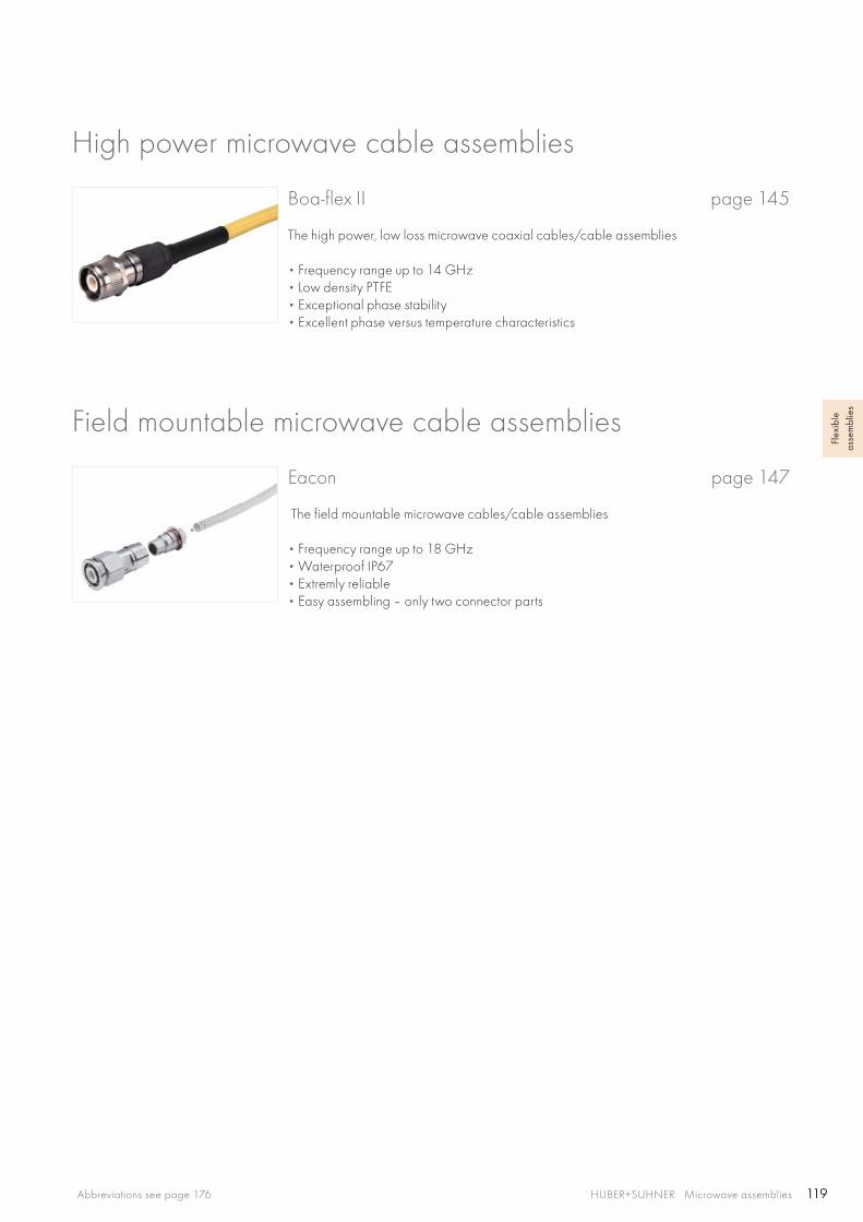
119HUBER+SUHNER Microwave assembliesAbbreviations see page 176
Flex
ible
as
sem
blie
s
High power microwave cable assemblies
Field mountable microwave cable assemblies
Boa-flex II page 145
The high power, low loss microwave coaxial cables/cable assemblies
• Frequency range up to 14 GHz • Low density PTFE• Exceptional phase stability• Excellent phase versus temperature characteristics
Eacon page 147
The field mountable microwave cables/cable assemblies
• Frequency range up to 18 GHz • Waterproof IP67• Extremly reliable • Easy assembling – only two connector parts
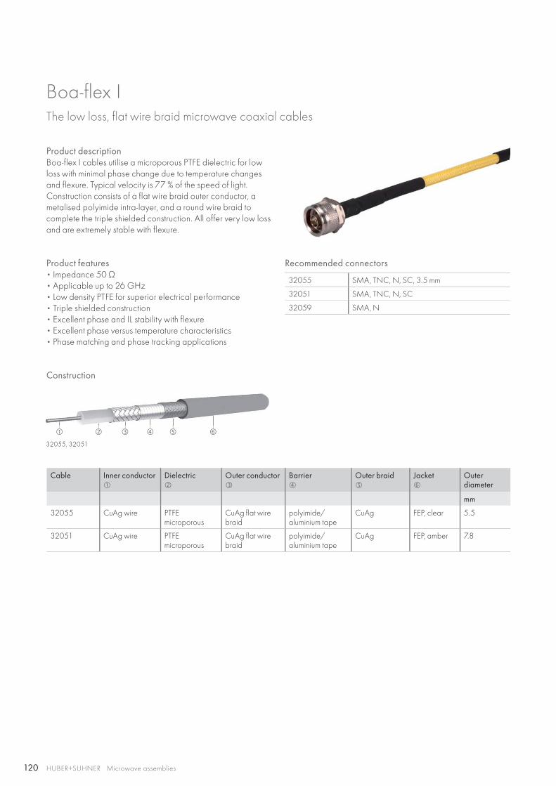
120
32055, 32051
HUBER+SUHNER Microwave assemblies
Construction
Cable Inner conductor
Dielectric
Outer conductor
Barrier
Outer braid
Jacket
Outerdiameter
mm
32055 CuAg wire PTFEmicroporous
CuAg flat wire braid
polyimide/aluminium tape
CuAg FEP, clear 5.5
32051 CuAg wire PTFEmicroporous
CuAg flat wire braid
polyimide/aluminium tape
CuAg FEP, amber 7.8
Recommended connectors
32055 SMA, TNC, N, SC, 3.5 mm
32051 SMA, TNC, N, SC
32059 SMA, N
Product descriptionBoa-flex I cables utilise a microporous PTFE dielectric for low loss with minimal phase change due to temperature changes and flexure. Typical velocity is 77 % of the speed of light. Construction consists of a flat wire braid outer conductor, a metalised polyimide intra-layer, and a round wire braid to complete the triple shielded construction. All offer very low loss and are extremely stable with flexure.
Boa-flex IThe low loss, flat wire braid microwave coaxial cables
Product features• Impedance 50 Ω• Applicable up to 26 GHz • Low density PTFE for superior electrical performance• Triple shielded construction• Excellent phase and IL stability with flexure• Excellent phase versus temperature characteristics• Phase matching and phase tracking applications

121
32059
HUBER+SUHNER Microwave assembliesAbbreviations see page 176
Flex
ible
as
sem
blie
s
Cable Inner conductor
Dielectric
Outerconductor
Barrier
1. Outer braid
2. Outer braid
3. Outer braid
Jacket
Outerdiameter
mm
32059 CuAg strand PTFEmicroporous
CuAg flat wire braid
polyimide/aluminium tape
CuAg CuAg CuAg FEP, clear
7.2
Technical data
Cable Item no. Max. operating frequency
Velocity ofpropagation
Weight Min. bending radii Temperature range
GHz % g/m static mm repeated mm °C
32055 80310948 26 77.3 64.0 22.9 68.6 −55 to +200
32051 80310945 18 77.8 114.6 34.3 102.9
32059 80310951 26 77.3 135.4 25.4 76.2
Construction
Boa-flex IThe low loss, flat wire braid microwave coaxial cables
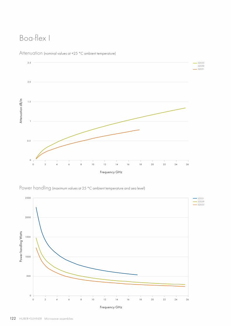
122
0 2 4 6 8 10 12 14 16 18 20 22 24 26
0 2 4 6 8 10 12 14 16 18 20 22 24 26
1.5
2.0
2.5
1
1000
1500
2000
2500
0.5
500
0
0
320553205932051
320513205932055
HUBER+SUHNER Microwave assemblies
Boa-flex I
Attenuation (nominal values at +25 °C ambient temperature)
Power handling (maximum values at 25 °C ambient temperature and sea level)
Atte
nuat
ion
dB/m
Pow
er h
andl
ing
Wat
ts
Frequency GHz
Frequency GHz
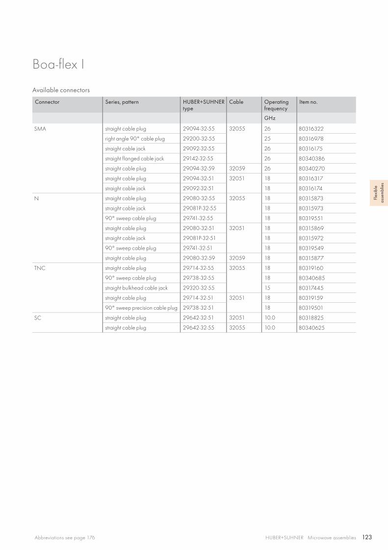
123HUBER+SUHNER Microwave assembliesAbbreviations see page 176
Flex
ible
as
sem
blie
s
Available connectors
Connector Series, pattern HUBER+SUHNER type
Cable Operating frequency
Item no.
GHz
SMA straight cable plug 29094-32-55 32055 26 80316322
right angle 90° cable plug 29200-32-55 25 80316978
straight cable jack 29092-32-55 26 80316175
straight flanged cable jack 29142-32-55 26 80340386
straight cable plug 29094-32-59 32059 26 80340270
straight cable plug 29094-32-51 32051 18 80316317
straight cable jack 29092-32-51 18 80316174
N straight cable plug 29080-32-55 32055 18 80315873
straight cable jack 29081P-32-55 18 80315973
90° sweep cable plug 29741-32-55 18 80319551
straight cable plug 29080-32-51 32051 18 80315869
straight cable jack 29081P-32-51 18 80315972
90° sweep cable plug 29741-32-51 18 80319549
straight cable plug 29080-32-59 32059 18 80315877
TNC straight cable plug 29714-32-55 32055 18 80319160
90° sweep cable plug 29738-32-55 18 80340685
straight bulkhead cable jack 29320-32-55 15 80317445
straight cable plug 29714-32-51 32051 18 80319159
90° sweep precision cable plug 29738-32-51 18 80319501
SC straight cable plug 29642-32-51 32051 10.0 80318825
straight cable plug 29642-32-55 32055 10.0 80340625
Boa-flex I
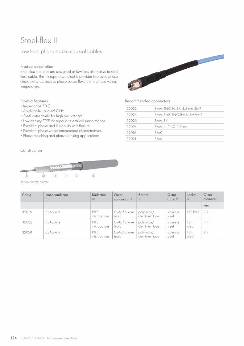
124
32016, 32022, 32024
HUBER+SUHNER Microwave assemblies
Construction
Recommended connectors
32022 SMA, TNC, N, SK, 3.5 mm, SMP
32024 SMA, SMP, TNC, BMA, SMPM-T
32026 SMA, SK
32094 SMA, N, TNC, 3.5 mm
32016 SMK
32021 SMA
Cable Inner conductor
Dielectric
Outerconductor
Barrier
Outer braid
Jacket
Outerdiameter
mm
32016 CuAg wire PTFEmicroporous
CuAg flat wire braid
polyimide/ aluminium tape
stainless steel
FEP, blue 3.2
32022 CuAg wire PTFEmicroporous
CuAg flat wire braid
polyimide/ aluminium tape
stainless steel
FEP, clear
3.7
32024 CuAg wire PTFEmicroporous
CuAg flat wire braid
polyimide/ aluminium tape
stainless steel
FEP, clear
2.7
Product descriptionSteel-flex II cables are designed as low loss alternative to steel-flex I cable. The microporous dielectric provides improved phase characteristics, such as phase versus flexure and phase versus temperature.
Steel-flex IILow loss, phase stable coaxial cables
Product features• Impedance 50 Ω• Applicable up to 45 GHz • Steel outer shield for high pull strength• Low density PTFE for superior electrical performance• Excellent phase and IL stability with flexure• Excellent phase versus temperature characteristics• Phase matching and phase tracking applications

125
32094
32021, 32026
HUBER+SUHNER Microwave assembliesAbbreviations see page 176
Flex
ible
as
sem
blie
s
Cable Inner conductor
Dielectric
Outerconductor
Barrier
1. Outer braid
2. Outer braid
3. Outer braid
Jacket
Outerdiameter
mm
32021 CuAg wire PTFEmicroporous
CuAg flat wire braid
polyimide/aluminium tape
stainless steel
CuAg CuAg FEP, blue 3.7
32026 CuAg wire PTFEmicroporous
CuAg flat wire braid
polyimide/aluminium tape
stainless steel
CuAg CuAg FEP, blue 4.9
Cable Inner conductor
Dielectric
Outerconductor
Barrier
Outer braid
Jacket
Outerdiameter
mm
32094 CuAg strand PTFEmicroporous
CuAg flat wire braid
polyimide / aluminium tape
stainless steel
FEP, clear
5.5
Technical data
Cable Item no. Max. operating frequency
Velocity of propagation
Weight Min. bending radii Temperature range
GHz % g/m static mm repeated mm °C
32016 80376532 45 76.5 26.8 8.4 25.1 −55 to +200
32021 80310919 45 76.5 40.2 8.4 25.1
32022 80310920 40 76.3 31.3 8.4 25.1
32024 80310922 40 76.5 16.4 6.4 19.1
32026 80310924 40 76.3 62.5 17.8 53.3
32094 80310965 26 77 61.0 22.8 68.6
Construction
Steel-flex II
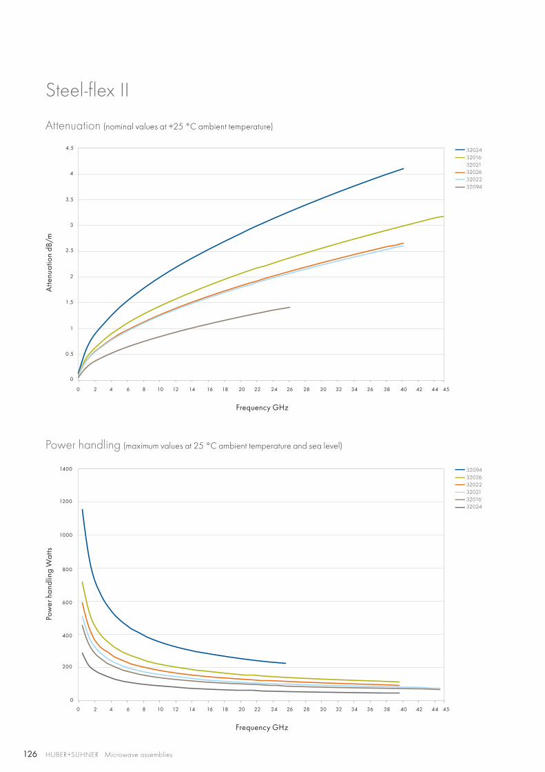
126
0 2 4 6 8 10 12 14 16 18 20 22 24 26 28 30 32 34 36 38 40 42 44 45
0 2 4 6 8 10 12 14 16 18 20 22 24 26 28 30 32 34 36 38 40 42 44 45
1400
1200
1000
1
2
3
4
0.5
1.5
2.5
3.5
4.5
200
400
600
800
0
0
320243201632021320263202232094
320943202632022320213201632024
HUBER+SUHNER Microwave assemblies
Steel-flex II
Attenuation (nominal values at +25 °C ambient temperature)
Power handling (maximum values at 25 °C ambient temperature and sea level)
Atte
nuat
ion
dB/m
Pow
er h
andl
ing
Wat
ts
Frequency GHz
Frequency GHz
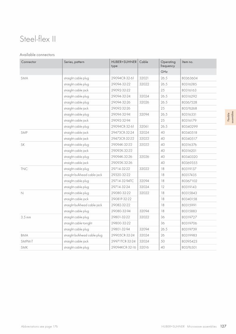
127HUBER+SUHNER Microwave assembliesAbbreviations see page 176
Flex
ible
as
sem
blie
s
Available connectors
Connector Series, pattern HUBER+SUHNER type
Cable Operating frequency
Item no.
GHz
SMA straight cable plug 29094CR-32-61 32021 26.5 80363604
straight cable plug 29094-32-22 32022 26.5 80316285
straight cable jack 29092-32-22 25 80316163
straight cable plug 29094-32-24 32024 26.5 80316292
straight cable plug 29094-32-26 32026 26.5 80367528
straight cable jack 29092-32-26 25 80376268
straight cable plug 29094-32-94 32094 26.5 80316331
straight cable jack 29092-32-94 25 80316179
straight cable plug 29094CR-32-61 32061 26.5 80340299
SMP straight cable jack 29473CR-32-24 32024 40 80340518
straight cable jack 29473CR-32-22 32022 40 80340517
SK straight cable plug 29094K-32-22 32022 40 80316376
straight cable jack 29092K-32-22 40 80316201
straight cable plug 29094K-32-26 32026 40 80340320
straight cable jack 29092K-32-26 40 80369355
TNC straight cable plug 29714-32-22 32022 18 80319137
straight bulkhead cable jack 29320-32-22 18 80317435
straight cable plug 29714-32-94TC 32094 18 80367102
straight cable plug 29714-32-24 32024 12 80319143
N straight cable plug 29080-32-22 32022 18 80315843
straight cable jack 29081P-32-22 18 80340158
straight bulkhead cable jack 29082-32-22 18 80315991
straight cable plug 29080-32-94 32094 18 80315883
3.5 mm straight cable plug 29801-32-22 32022 36 80319727
straight cable tonight 29800-32-22 36 80319706
straight cable plug 29801-32-94 32094 26.5 80319739
BMA straight bulkhead cable plug 29905CR-32-24 32024 26 80319983
SMPM-T straight cable jack 29971TCR-32-24 32024 50 80395423
SMK straight cable plug 29094KCR-32-16 32016 40 80376501
Steel-flex II

128
32041, 32081, 32086, 32061
HUBER+SUHNER Microwave assemblies
Cable Inner conductor
Dielectric
Outerconductor
Barrier
Outer braid
Jacket
Outerdiameter
mm
32041 CuAg wire PTFE CuAg flat wire braid
polyimide/ aluminium tape
stainless steel
FEP, green
2.0
32061 CuAg wire PTFE CuAg flat wire braid
polyimide/ aluminium tape
stainless steel
FEP, grey 1.6
32081 CuAg wire PTFE CuAg flat wire braid
polyimide/ aluminium tape
stainless steel
FEP,blue
2.6
32086 CuAg strand PTFE CuAg flat wire braid
PTFE tape stainless steel
FEP, clear 2.7
Construction
Recommended connectors
32041 SMPM, SMPM-T, BMA, SMP
32061 SMA, 1 mm
32081 SMA, N, SSMA, TNC, SMP
32086 SMA
32091 SMA, SMK
Product descriptionSteel-flex cables are lightweight flexible replacements to semi-rigid cable. All utilise triple shields for superior RF shielding, with a solid TFE dielectric for exceptional crush resistance with-out the need for heavy armor. The flat wire braid outer conduc-tor provides low loss plus excellent insertion loss stability with flexure. The stainless steel outer braid provides improved me-chanical pull strength when compared to cables with a copper wire outer braid.
Steel-flex IHigh performance, high pull strength microwave coaxial cables
Product features• Impedance 50 Ω• Applicable up to 85 GHz • Designed for low cost/high volume applications• Excellent loss stability over flexure• Steel outer shield for high pull strength• UL approved
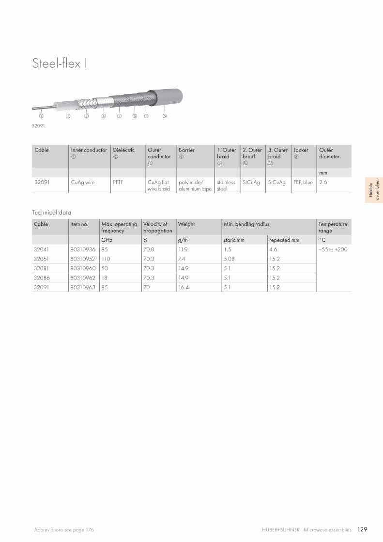
129
32091
HUBER+SUHNER Microwave assembliesAbbreviations see page 176
Flex
ible
as
sem
blie
s
Cable Inner conductor
Dielectric
Outer conductor
Barrier
1. Outer braid
2. Outer braid
3. Outer braid
Jacket
Outerdiameter
mm
32091 CuAg wire PFTF CuAg flat wire braid
polyimide/aluminium tape
stainless steel
StCuAg StCuAg FEP, blue 2.6
Steel-flex I
Technical data
Cable Item no. Max. operating frequency
Velocity of propagation
Weight Min. bending radius Temperature range
GHz % g/m static mm repeated mm °C
32041 80310936 85 70.0 11.9 1.5 4.6 −55 to +200
32061 80310952 110 70.3 7.4 5.08 15.2
32081 80310960 50 70.3 14.9 5.1 15.2
32086 80310962 18 70.3 14.9 5.1 15.2
32091 80310963 85 70 16.4 5.1 15.2
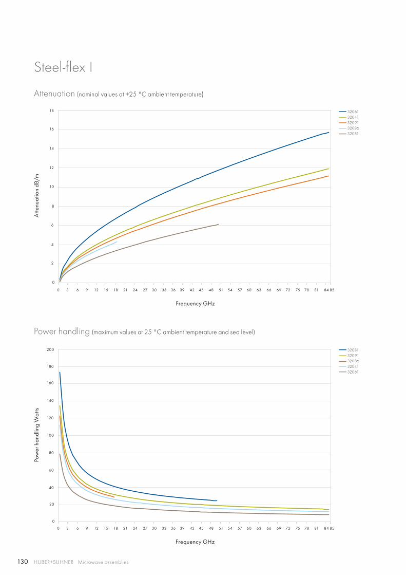
130
12
14
16
18
8
10
40
60
80
100
120
140
160
180
200
4
6
2
20
0
0
0 3 6 9 12 15 18 21 24 27 30 33 36 39 42 45 48 51 54 57 60 63 66 69 72 75 78 81 84 85
0 3 6 9 12 15 18 21 24 27 30 33 36 39 42 45 48 51 54 57 60 63 66 69 72 75 78 81 84 85
3206132041320913208632081
3208132091320863204132061
HUBER+SUHNER Microwave assemblies
Steel-flex I
Attenuation (nominal values at +25 °C ambient temperature)
Power handling (maximum values at 25 °C ambient temperature and sea level)
Atte
nuat
ion
dB/m
Pow
er h
andl
ing
Wat
ts
Frequency GHz
Frequency GHz
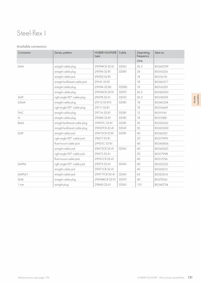
131HUBER+SUHNER Microwave assembliesAbbreviations see page 176
Flex
ible
as
sem
blie
s
Available connectors
Connector Series, pattern HUBER+SUHNER type
Cable Operating frequency
Item no.
GHz
SMA straight cable plug 29094CR-32-61 32061 26.5 80340299
straight cable plug 29094-32-81 32081 24 80316324
straight cable jack 29092-32-81 18 80316176
straight bulkhead cable jack 29141-32-81 18 80340377
straight cable plug 29094-32-86 32086 18 80316329
straight cable plug 29094CR-32-91 32091 26.5 80340300
SMP right angle 90° cable plug 29478-32-41 32041 26.5 80318009
SSMA straight cable plug 29112-32-81S 32081 18 80340358
right angle 90° cable plug 29111-32-81 18 80316669
TNC straight cable plug 29714-32-81 32081 12 80319161
N straight cable plug 29080-32-81 32081 18 80315881
BMA straight bulkhead cable plug 29907C-32-81 32081 26 80320002
straight bulkhead cable plug 29907CR-32-41 32041 26 80320009
SMP straight cable jack 29473CR-32-81 32081 40 80340521
right angle 90° cable jack 29477-32-81 20 80317999
float mount cable jack 29921C-32-81 40 80340806
straight cable jack 29473CR-32-41 32041 40 80340520
right angle 90° cable jack 29473-32-41 20 80317998
float mount cable jack 29921CR-32-41 40 80317036
SMPM right angle 90° cable jack 29973-32-41 32041 40 80320222
straight cable jack 29971CR-32-41 40 80320212
SMPM-T straight cable jack 29971TCR-32-41 32041 65 80320214
SMK straight cable plug 29094KCR-32-91 32091 40 80370561
1 mm straight plug 29840-32-61 32061 110 80340724
Steel-flex I
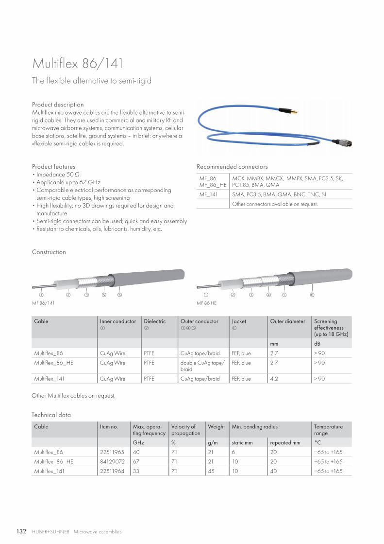
132
MF 86/141 MF 86 HE
HUBER+SUHNER Microwave assemblies
Multiflex 86/141The flexible alternative to semi-rigid
Product descriptionMultiflex microwave cables are the flexible alternative to semi-rigid cables. They are used in commercial and military RF and microwave airborne systems, communication systems, cellular base stations, satellite, ground systems – in brief: anywhere a «flexible semi-rigid cable» is required.
Product features• Impedance 50 Ω• Applicable up to 67 GHz• Comparable electrical performance as corresponding
semi-rigid cable types, high screening• High flexibility: no 3D drawings required for design and
manufacture• Semi-rigid connectors can be used; quick and easy assembly• Resistant to chemicals, oils, lubricants, humidity, etc.
Cable Inner conductor
Dielectric
Outer conductor
Jacket
Outer diameter Screeningeffectiveness(up to 18 GHz)
mm dB
Multiflex_86 CuAg Wire PTFE CuAg tape/braid FEP, blue 2.7 > 90
Multiflex_86_HE CuAg Wire PTFE double CuAg tape/braid
FEP, blue 2.7 > 90
Multiflex_141 CuAg Wire PTFE CuAg tape/braid FEP, blue 4.2 > 90
Other Multiflex cables on request.
Recommended connectors
MF_86MF_86_HE
MCX, MMBX, MMCX, MMPX, SMA, PC3.5, SK, PC1.85, BMA, QMA
MF_141 SMA, PC3.5, BMA, QMA, BNC, TNC, N
Other connectors available on request.
Technical data
Cable Item no. Max. opera-ting frequency
Velocity ofpropagation
Weight Min. bending radius Temperature range
GHz % g/m static mm repeated mm °C
Multiflex_86 22511965 40 71 21 6 20 −65 to +165
Multiflex_86_HE 84129072 67 71 21 10 20 −65 to +165
Multiflex_141 22511964 33 71 45 10 40 −65 to +165
Construction
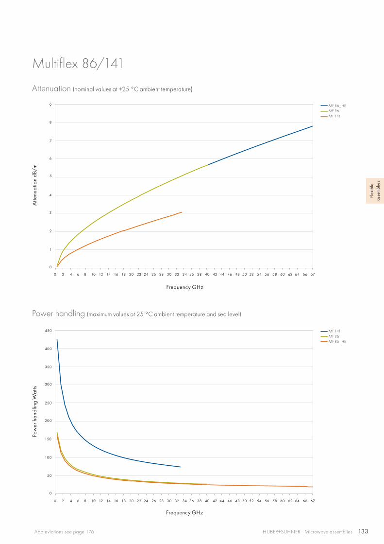
133
5
6
7
8
9
1
2
3
4
0
0
50
100
150
200
250
300
350
400
450
0 2 4 6 8 10 12 14 16 18 20 22 24 26 28 30 32 34 36 38 40 42 44 46 48 50 52 54 56 58 60 62 64 66 67
0 2 4 6 8 10 12 14 16 18 20 22 24 26 28 30 32 34 36 38 40 42 44 46 48 50 52 54 56 58 60 62 64 66 67
MF 86_HEMF 86MF 141
MF 141MF 86MF 86_HE
HUBER+SUHNER Microwave assembliesAbbreviations see page 176
Flex
ible
as
sem
blie
s
Multiflex 86/141
Attenuation (nominal values at +25 °C ambient temperature)
Power handling (maximum values at 25 °C ambient temperature and sea level)
Atte
nuat
ion
dB/m
Pow
er h
andl
ing
Wat
ts
Frequency GHz
Frequency GHz

134 HUBER+SUHNER Microwave assemblies
Multiflex 86/141
Available connectors
Connector Series, pattern HUBER+SUHNER type Cable Operating frequency
Item no.
GHz
MCX straight cable plug 11_MCX-50-2-19/111_NE MF 86 / MF 86_HE 6 23024699
right angle cable plug 16_MCX-50-2-104/111_NH-1 6 23032067
right angle cable plug 16_MCX-50-2-104/111_NH 6 22658277
straight panel bulkhead cable jack 24_MCX-50-2-3/111_NE 6 22543580
MMBX straight cable plug 11_MMBX-50-2-4/111_NE MF 86 / MF 86_HE 12.4 84026769
right angle cable plug 16_MMBX-50-2-4/111_NE 12.4 84026740
straight panel bulkhead cable jack 24_MMBX-50-2-2/111_NH 12.4 23037876
MMCX straight cable plug 11_MMCX-50-2-1/111_OE MF 86 / MF 86_HE 6 22645297
right angle cable plug 16_MMCX-50-2-13/111_OE 6 84032569
straight cable jack 21_MMCX-50-2-1/111_OE 6 22645290
straight panel bulkhead cable jack 24_MMCX-50-2-1/111_OE 6 22645954
MMPX straight cable plug 11_MMPX-50-2-3/111_NE MF 86_HE 67 84089228
right angle cable plug 16_MMPX-50-2-2/111_NE MF 86_HE 67 84067778
N straight cable plug 11_N-50-2-15/113_UE MF 86 / MF 86_HE 18 22660315
right angle cable plug 16_N-50-2-9/13-_UH 11 23013729
straight cable jack 21_N-50-2-14/133_NE 18 22642666
straight panel bulkhead cable jack 24_N-50-2-14/133_NE 18 22544637
straight panel cable jack, flange mount 25_N-50-2-14/133_NE 18 22641303
PC 1.85 straight cable plug 11_PC185-50-2-4/19-_NE MF 86_HE 67 84144282
straight cable jack 21_PC185-50-2-4/19-_NE 67 84144175
PC 3.5 straight cable plug 11_PC35-50-2-5/199_UE MF 86_HE 33 84139219
straight cable jack 21_PC35-50-2-5/199_UE 33 84139085
straight panel bulkhead cable jack 24_PC35-50-2-5/199_UE 33 84139301
QMA straight cable plug 11_QMA-50-2-3/133_NE MF 86 / MF 86_HE 6 23017704
right angle cable plug 16_QMA-50-2-3/133_NE 6 23017666
straight panel bulkhead cable jack 24_QMA-50-2-1/111_NE 6 23017742
SK straight cable plug 11_SK-50-2-60/199_NE MF 86_HE 40 84098644
straight cable jack 21_SK-50-2-61/199_NE 40 84094378
SMA straight cable plug 11_SMA-50-2-65/119_NE MF 86 / MF 86_HE 18 22642315
right angle cable plug 16_SMA-50-2-43/133_NE 18 22641953
straight cable jack 21_SMA-50-2-15/111_NE 18 22544549
straight panel bulkhead cable jack 24_SMA-50-2-15/111_NE 18 22544532
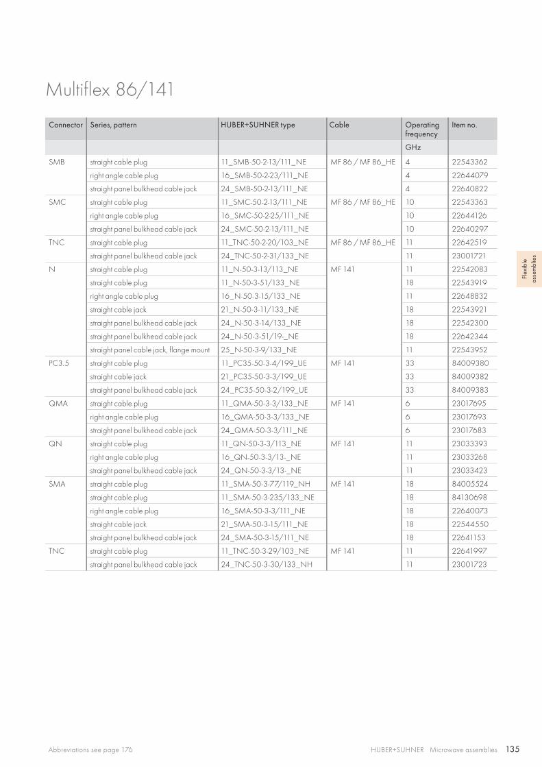
135HUBER+SUHNER Microwave assembliesAbbreviations see page 176
Flex
ible
as
sem
blie
s
Multiflex 86/141
Connector Series, pattern HUBER+SUHNER type Cable Operating frequency
Item no.
GHz
SMB straight cable plug 11_SMB-50-2-13/111_NE MF 86 / MF 86_HE 4 22543362
right angle cable plug 16_SMB-50-2-23/111_NE 4 22644079
straight panel bulkhead cable jack 24_SMB-50-2-13/111_NE 4 22640822
SMC straight cable plug 11_SMC-50-2-13/111_NE MF 86 / MF 86_HE 10 22543363
right angle cable plug 16_SMC-50-2-25/111_NE 10 22644126
straight panel bulkhead cable jack 24_SMC-50-2-13/111_NE 10 22640297
TNC straight cable plug 11_TNC-50-2-20/103_NE MF 86 / MF 86_HE 11 22642519
straight panel bulkhead cable jack 24_TNC-50-2-31/133_NE 11 23001721
N straight cable plug 11_N-50-3-13/113_NE MF 141 11 22542083
straight cable plug 11_N-50-3-51/133_NE 18 22543919
right angle cable plug 16_N-50-3-15/133_NE 11 22648832
straight cable jack 21_N-50-3-11/133_NE 18 22543921
straight panel bulkhead cable jack 24_N-50-3-14/133_NE 18 22542300
straight panel bulkhead cable jack 24_N-50-3-51/19-_NE 18 22642344
straight panel cable jack, flange mount 25_N-50-3-9/133_NE 11 22543952
PC3.5 straight cable plug 11_PC35-50-3-4/199_UE MF 141 33 84009380
straight cable jack 21_PC35-50-3-3/199_UE 33 84009382
straight panel bulkhead cable jack 24_PC35-50-3-2/199_UE 33 84009383
QMA straight cable plug 11_QMA-50-3-3/133_NE MF 141 6 23017695
right angle cable plug 16_QMA-50-3-3/133_NE 6 23017693
straight panel bulkhead cable jack 24_QMA-50-3-3/111_NE 6 23017683
QN straight cable plug 11_QN-50-3-3/113_NE MF 141 11 23033393
right angle cable plug 16_QN-50-3-3/13-_NE 11 23033268
straight panel bulkhead cable jack 24_QN-50-3-3/13-_NE 11 23033423
SMA straight cable plug 11_SMA-50-3-77/119_NH MF 141 18 84005524
straight cable plug 11_SMA-50-3-235/133_NE 18 84130698
right angle cable plug 16_SMA-50-3-3/111_NE 18 22640073
straight cable jack 21_SMA-50-3-15/111_NE 18 22544550
straight panel bulkhead cable jack 24_SMA-50-3-15/111_NE 18 22641153
TNC straight cable plug 11_TNC-50-3-29/103_NE MF 141 11 22641997
straight panel bulkhead cable jack 24_TNC-50-3-30/133_NH 11 23001723

136
HUBER+SUHNER Microwave assemblies
S-series The economical, low loss microwave cable
Product descriptionThe S-series is a line of cost-efficient, low loss microwave ca-bles. It covers technically demanding requirements in a wide range of applications, preferably in fixed installations. These versatile cables are characterised by their very low insertion loss across a wide frequency range. S-series cables are easy to assemble and are made of environmentally friendly, halogen free materials.
Product features• Impedance 50 Ω• Applicable up to 18 GHz• Low insertion loss• Excellent screening effectiveness• Quick and easy to assemble• Low smoke, free of halogen free version available• Cost-efficient, environmentally friendly solution for
a wide range of applications
Cable Inner conductor
Dielectric
Outer conductor
Jacket
Outer diameter Screeningeffectivenessup to 18 GHz
mm dB
S_04272_B CuAg Wire SPE Al tape/CuSn braid PE, blue 5.5 > 90
S_04262_B-01 CuAg Wire SPE Al tape/CuSn braid LSFH, black 5.5 > 90
S_04212_B CuAg Wire SPE Al tape/CuSn braid PUR, black 5.5 > 90
Recommended connectors
S_04272_B SMA, TNC, N
S_04262_B-01 SMA, TNC, N
Other connectors available on request.
Technical data
Cable Item no. Max. opera-ting frequency
Velocity ofpropagation
Weight Min. bending radius Temperature range
GHz % g/m static mm repeated mm °C
S_04272_B 22511622 18 82 44 25 90 −40 to +85
S_04262_B-01 84000918 18 82 41 25 90
S_04212_B 22511855 18 82 41 25 90
Construction
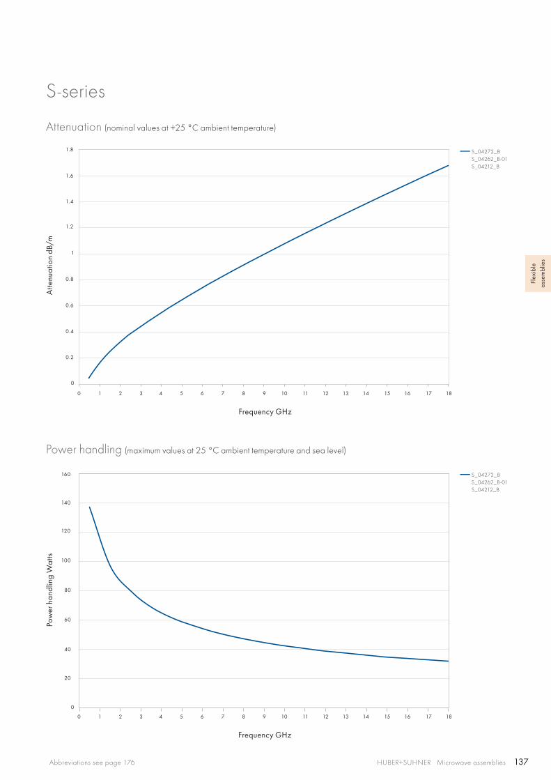
137
0 1 2 3 4 5 6 7 8 9 10 11 12 13 14 15 16 17 18
0 1 2 3 4 5 6 7 8 9 10 11 12 13 14 15 16 17 18
1
1.4
1.6
1.8
1.2
0.2
0.4
0.6
0.8
0
0
20
40
60
80
100
120
140
160
S_04272_BS_04262_B-01S_04212_B
S_04272_BS_04262_B-01S_04212_B
HUBER+SUHNER Microwave assembliesAbbreviations see page 176
Flex
ible
as
sem
blie
s
S-series
Attenuation (nominal values at +25 °C ambient temperature)
Power handling (maximum values at 25 °C ambient temperature and sea level)
Atte
nuat
ion
dB/m
Pow
er h
andl
ing
Wat
ts
Frequency GHz
Frequency GHz
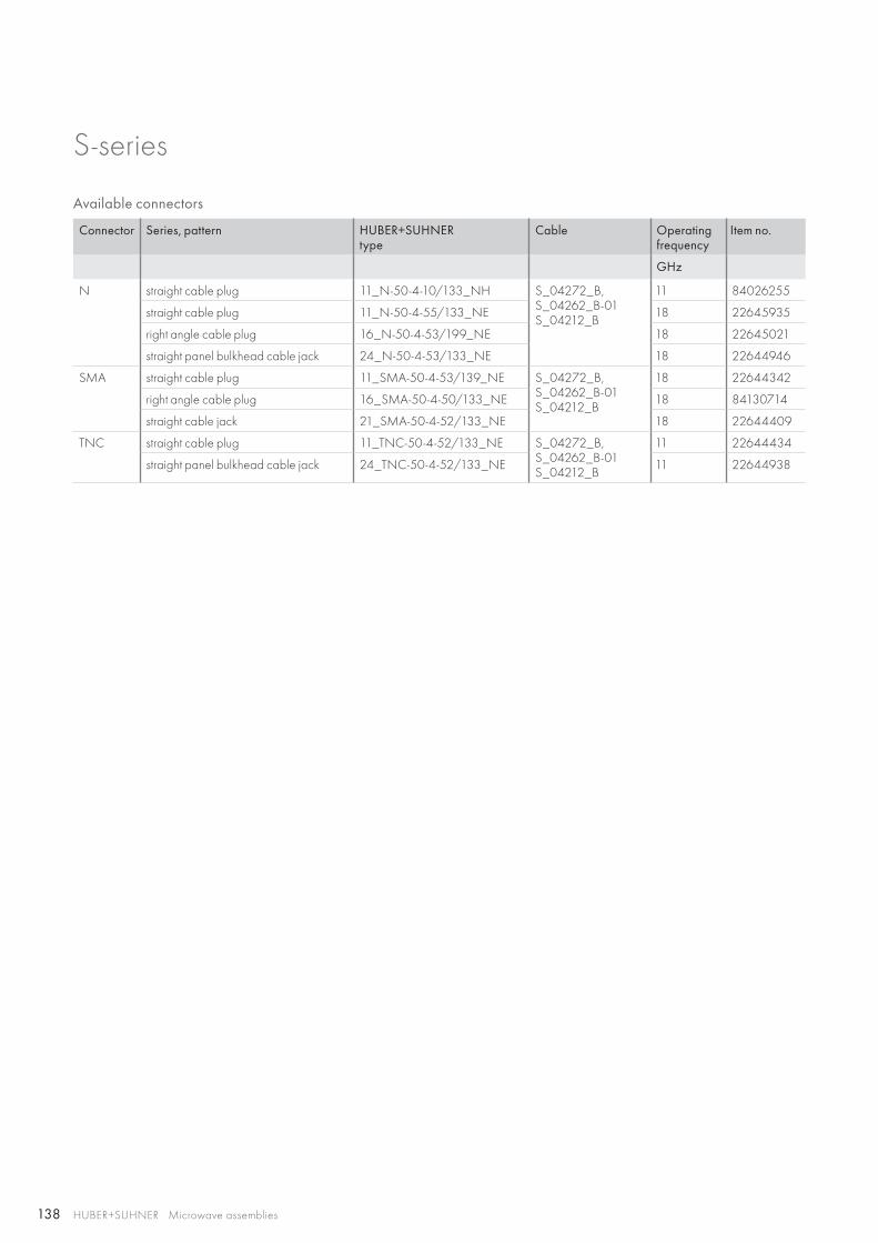
138 HUBER+SUHNER Microwave assemblies
S-series
Available connectors
Connector Series, pattern HUBER+SUHNERtype
Cable Operating frequency
Item no.
GHz
N straight cable plug 11_N-50-4-10/133_NH S_04272_B, S_04262_B-01S_04212_B
11 84026255
straight cable plug 11_N-50-4-55/133_NE 18 22645935
right angle cable plug 16_N-50-4-53/199_NE 18 22645021
straight panel bulkhead cable jack 24_N-50-4-53/133_NE 18 22644946
SMA straight cable plug 11_SMA-50-4-53/139_NE S_04272_B, S_04262_B-01S_04212_B
18 22644342
right angle cable plug 16_SMA-50-4-50/133_NE 18 84130714
straight cable jack 21_SMA-50-4-52/133_NE 18 22644409
TNC straight cable plug 11_TNC-50-4-52/133_NE S_04272_B, S_04262_B-01S_04212_B
11 22644434
straight panel bulkhead cable jack 24_TNC-50-4-52/133_NE 11 22644938

139
HUBER+SUHNER Microwave assembliesAbbreviations see page 176
Flex
ible
as
sem
blie
sTechnical data
Cable Item no. Max. operating frequency
Velocity of propagation
Weight Min. bending radii Temperature range
GHz % g/m static mm repeated mm °C
32084 80310961 40 76 10.4 5.1 15.2 −55 to +200
Construction
Cable Inner conductor
Dielectric
Outer conductor
Outer tape
Jacket
Ruggedisation
Outerdiameter
mm
32084 CuAg strand PTFE,microporous
CuAgflat wire braid
polyimide/aluminium
silicone rubber stainless steel 2.4
Available connectors
Connector Series, pattern HUBER+SUHNER type
Cable Operating frequency
Item no.
GHz
SMA straight cable plug 29094-32-84 32084 18 80316327
right angle 90° cable plug 29200-32-84 18 80316980
SSMA straight cable plug 29112-32-84 18 80316698
right angle 90° cable plug 29111-32-84 12 80340354
SK straight cable plug 29094K-32-84 40 80316384
Product descriptionEver-flex cables were designed for use in ultradurable, high flexure applications such as gimbal assemblies and installa-tions where the cable assembly must endure multiple tight bends and twists. ever-flex cable assemblies have repeatedly endured 1 000 000 flexure cycles with minimal electrical and mechanical degradation. All incorporate a flat wire outer con-ductor and a microporous dielectric for low loss and a tight woven stainless steel outer braid for improved resistance to crushing, bending and kinking.
Ever-flexThe high flexibility microwave coaxial cable assemblies
Product features• Impedance 50 Ω• Applicable up to 40 GHz • High reliability• Light weight• Low loss• Broad bandwidth
Recommended connectors
32084 SMA, SSMA, SK
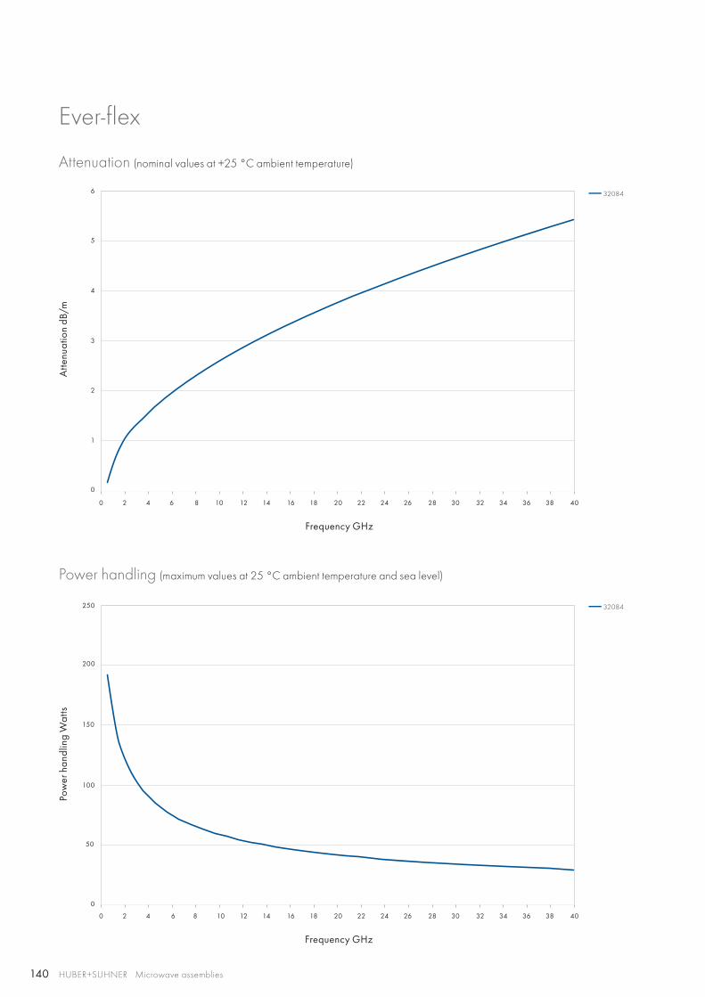
140
0 2 4 6 8 10 12 14 16 18 20 22 24 26 28 30 32 34 36 38 40
0 2 4 6 8 10 12 14 16 18 20 22 24 26 28 30 32 34 36 38 40
6
4
5
100
150
200
250
2
3
1
50
0
0
32084
32084
HUBER+SUHNER Microwave assemblies
Ever-flex
Attenuation (nominal values at +25 °C ambient temperature)
Power handling (maximum values at 25 °C ambient temperature and sea level)
Atte
nuat
ion
dB/m
Pow
er h
andl
ing
Wat
ts
Frequency GHz
Frequency GHz
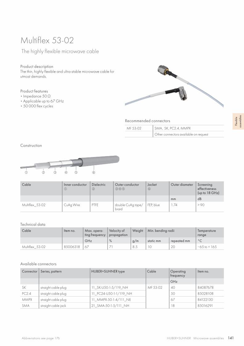
141
HUBER+SUHNER Microwave assembliesAbbreviations see page 176
Flex
ible
as
sem
blie
s
Product descriptionThe thin, highly flexible and ultra-stable microwave cable for utmost demands.
Product features• Impedance 50 Ω• Applicable up to 67 GHz • 50 000 flex cycles
Recommended connectors
MF 53-02 SMA, SK, PC2.4, MMPX
Other connectors available on request
Construction
Cable Inner conductor
Dielectric
Outer conductor
Jacket
Outer diameter Screeningeffectiveness(up to 18 GHz)
mm dB
Multiflex_53-02 CuAg Wire PTFE double CuAg tape/braid
FEP, blue 1.74 > 90
Technical dataCable Item no. Max. opera-
ting frequencyVelocity ofpropagation
Weight Min. bending radii Temperature range
GHz % g/m static mm repeated mm °C
Multiflex_53-02 85006318 67 71 8.5 10 20 −65 to + 165
Multiflex 53-02 The highly flexible microwave cable
Available connectors
Connector Series, pattern HUBER+SUHNER type Cable Operating frequency
Item no.
GHz
SK straight cable plug 11_SK-U50-1-5/119_NH MF 53-02 40 84087678
PC2.4 straight cable plug 11_PC24-U50-1-1/119_NH 50 85028108
MMPX straight cable plug 11_MMPX-50-1-4/111_NE 67 84122130
SMA straight cable jack 21_SMA-50-1-5/111_NH 18 85016291
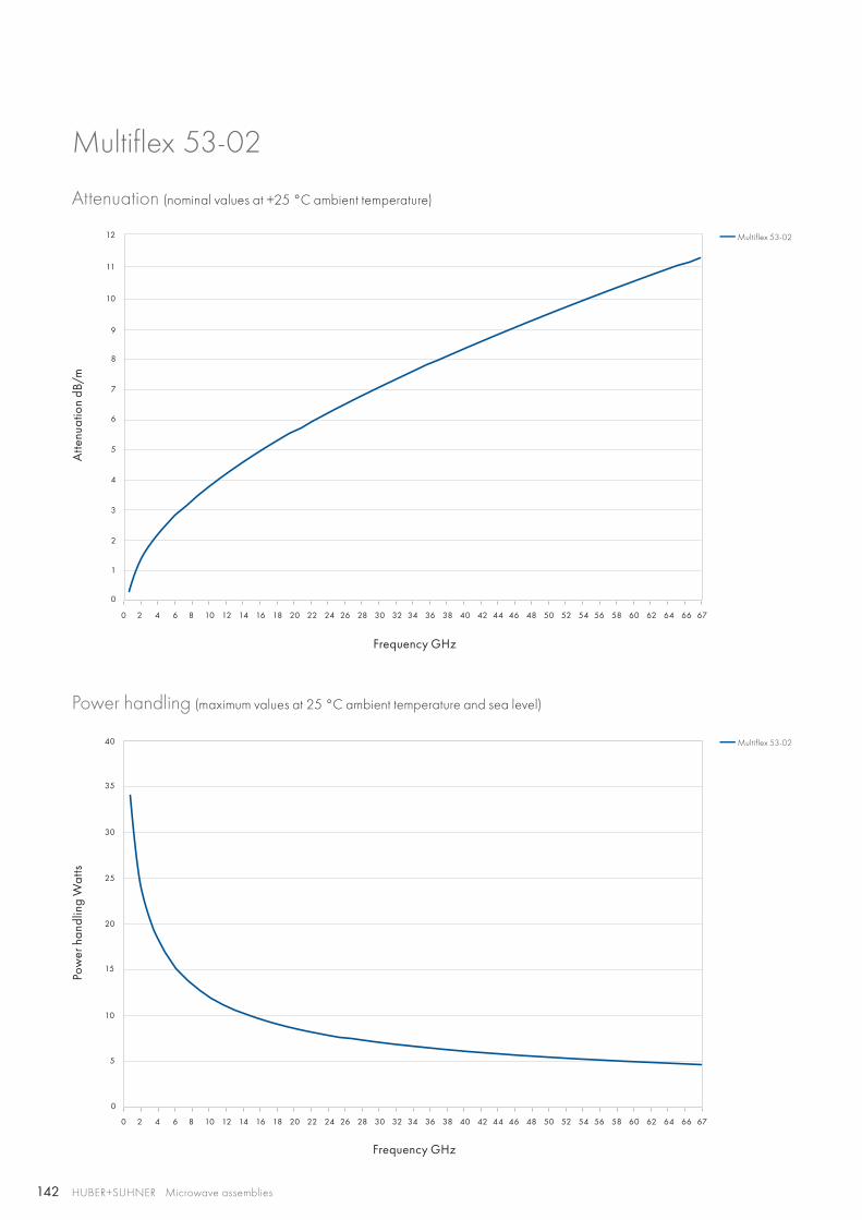
142
0 2 4 6 8 10 12 14 16 18 20 22 24 26 28 30 32 34 36 38 40 42 44 46 48 50 52 54 56 58 60 62 64 66 67
0 2 4 6 8 10 12 14 16 18 20 22 24 26 28 30 32 34 36 38 40 42 44 46 48 50 52 54 56 58 60 62 64 66 67
6
7
8
9
10
5
4
3
15
20
25
30
35
40
2
10
1
5
0
0
Multiflex 53-02
Multiflex 53-02
11
12
HUBER+SUHNER Microwave assemblies
Multiflex 53-02
Attenuation (nominal values at +25 °C ambient temperature)
Power handling (maximum values at 25 °C ambient temperature and sea level)
Atte
nuat
ion
dB/m
Pow
er h
andl
ing
Wat
ts
Frequency GHz
Frequency GHz
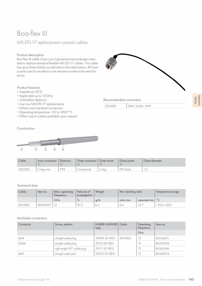
143
HUBER+SUHNER Microwave assembliesAbbreviations see page 176
Flex
ible
as
sem
blie
s
Technical data
Cable Item no. Max. operating frequency
Velocity of propagation
Weight Min. bending radii Temperature range
GHz % g/m static mm repeated mm °C
32018DS 80320957 12 70.3 4.5 4.6 13.7 −55 to +200
Construction
Cable Inner conductor
Dielectric
Outer conductor
Outer braid
Outer jacket
Outer diameter
32018DS CuAg wire PTFE CuAg braid CuAg FEP, black 1.3
Available connectors
Connector Series, pattern HUBER+SUHNER type
Cable Operatingfrequency
Item no.
GHz
SMA straight cable plug 29094-32-18DS 32018DS 12 80316273
SSMA straight cable plug 29112-32-18DS 12 80395393
right angle 90° cable plug 29111-32-18DS 12 80395394
SMP straight cable jack 29473-32-18DS 12 80340514
Recommended connectors
32018DS SMA, SSMA, SMP
Product descriptionBoa-flex III cable is low cost, high performance designs inten-ded to replace standard flexible MIL-DTL-17 cables. This cable has up to three shields as indicated in the table below. All have a solid core for excellent crush resistance without the need for armor.
Boa-flex IIIMIL-DTL-17 replacement coaxial cables
Product features• Impedance 50 Ω• Applicable up to 12 GHz • Solid teflon dielectric• Low loss MIL-DTL-17 replacements• Utilises most standard connectors• Operating temperature −55 to +200 °C• Other custom cables available upon request
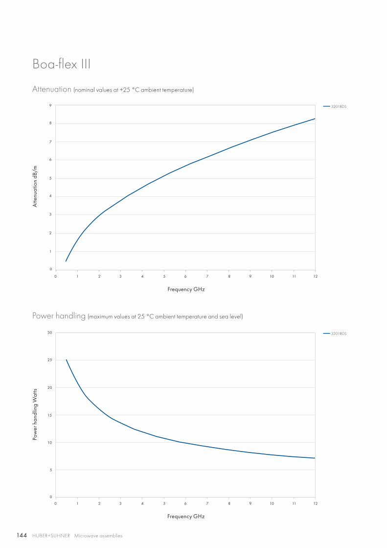
144
0 1 2 3 4 5 6 7 8 9 10 11 12
0 1 2 3 4 5 6 7 8 9 10 11 12
3
4
5
6
7
8
9
10
15
20
25
30
5
1
2
0
0
32018DS
32018DS
HUBER+SUHNER Microwave assemblies
Boa-flex III
Attenuation (nominal values at +25 °C ambient temperature)
Power handling (maximum values at 25 °C ambient temperature and sea level)
Atte
nuat
ion
dB/m
Pow
er h
andl
ing
Wat
ts
Frequency GHz
Frequency GHz
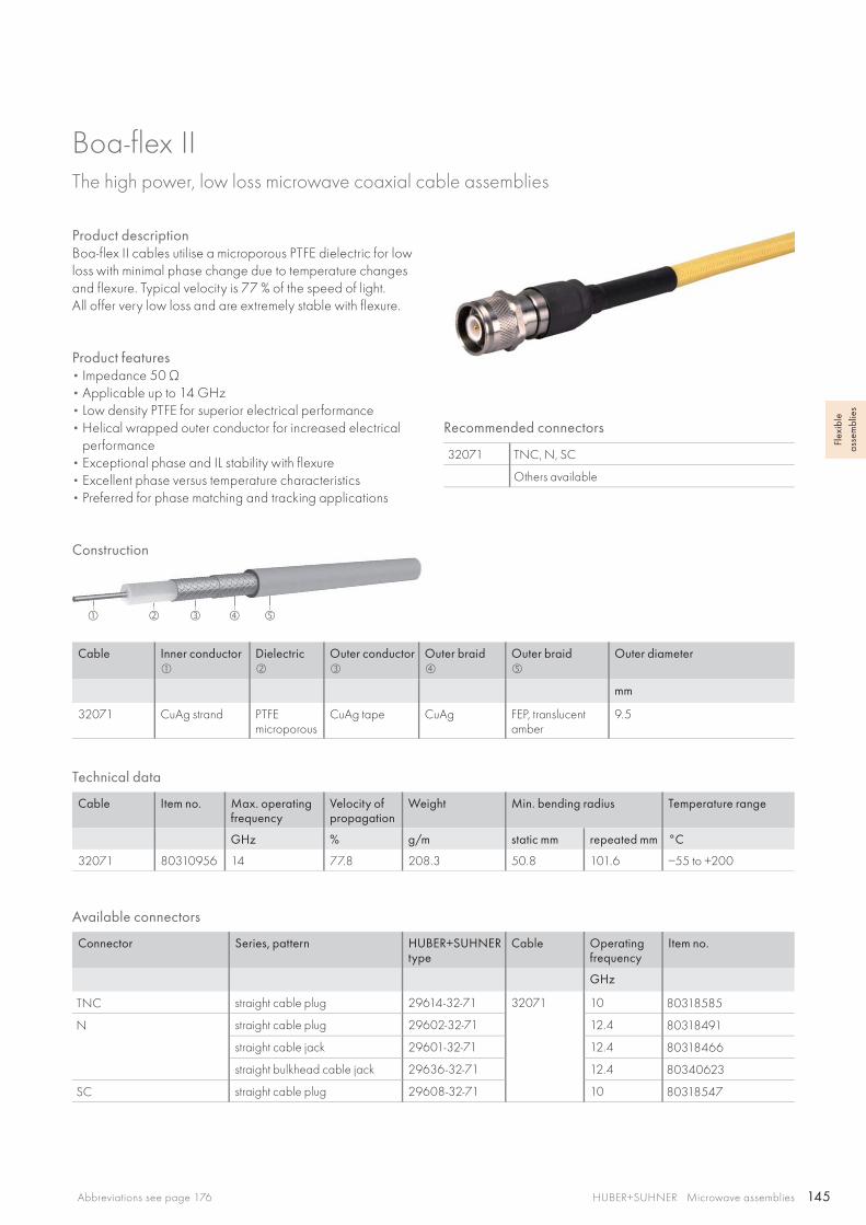
145
HUBER+SUHNER Microwave assembliesAbbreviations see page 176
Flex
ible
as
sem
blie
s
Technical data
Cable Item no. Max. operating frequency
Velocity of propagation
Weight Min. bending radius Temperature range
GHz % g/m static mm repeated mm °C
32071 80310956 14 77.8 208.3 50.8 101.6 −55 to +200
Construction
Cable Inner conductor
Dielectric
Outer conductor
Outer braid
Outer braid
Outer diameter
mm
32071 CuAg strand PTFEmicroporous
CuAg tape CuAg FEP, translucent amber
9.5
Available connectors
Connector Series, pattern HUBER+SUHNER type
Cable Operatingfrequency
Item no.
GHz
TNC straight cable plug 29614-32-71 32071 10 80318585
N straight cable plug 29602-32-71 12.4 80318491
straight cable jack 29601-32-71 12.4 80318466
straight bulkhead cable jack 29636-32-71 12.4 80340623
SC straight cable plug 29608-32-71 10 80318547
Product descriptionBoa-flex II cables utilise a microporous PTFE dielectric for low loss with minimal phase change due to temperature changes and flexure. Typical velocity is 77 % of the speed of light. All offer very low loss and are extremely stable with flexure.
Boa-flex IIThe high power, low loss microwave coaxial cable assemblies
Product features• Impedance 50 Ω• Applicable up to 14 GHz• Low density PTFE for superior electrical performance• Helical wrapped outer conductor for increased electrical
performance• Exceptional phase and IL stability with flexure• Excellent phase versus temperature characteristics• Preferred for phase matching and tracking applications
Recommended connectors
32071 TNC, N, SC
Others available
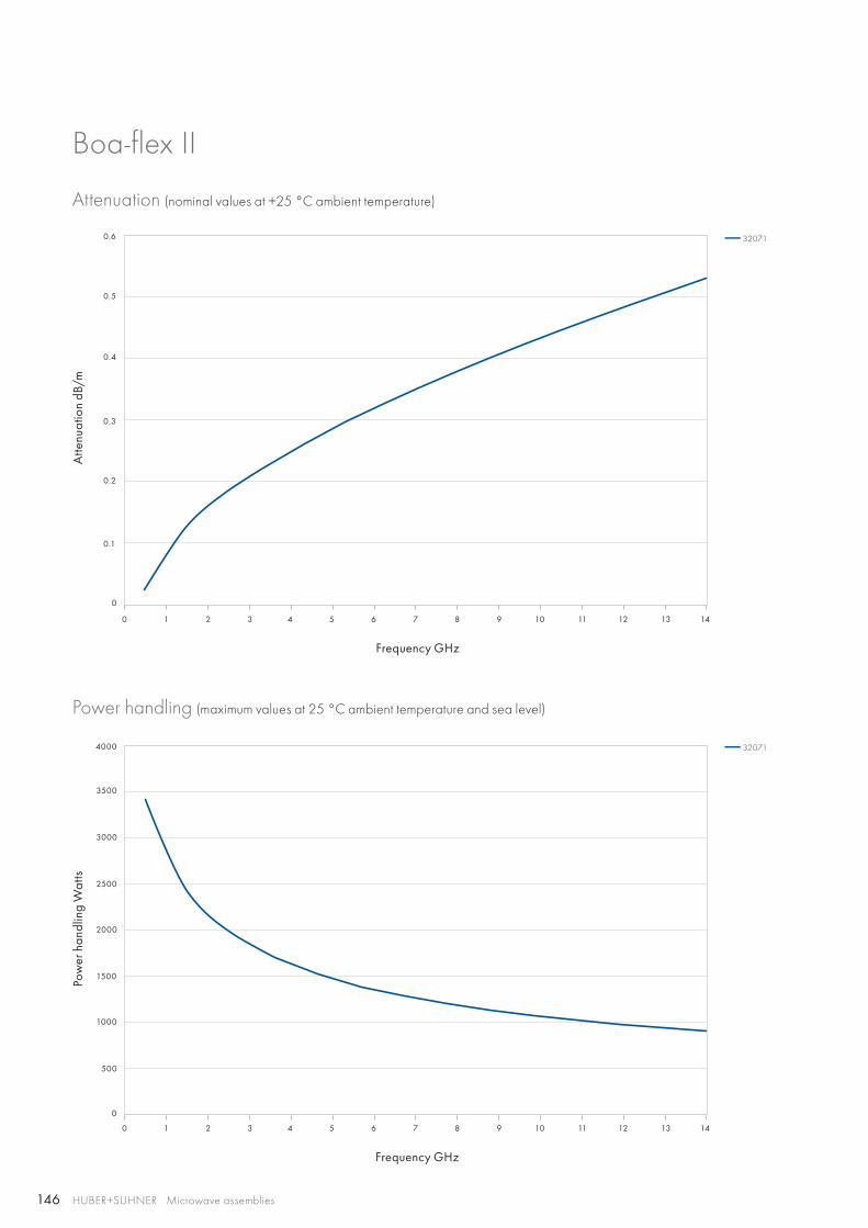
146
0 1 2 3 4 5 6 7 8 9 10 11 12 13 14
0 1 2 3 4 5 6 7 8 9 10 11 12 13 14
0.3
0.4
0.5
0.6
1000
1500
2000
2500
3000
3500
4000
500
0.1
0.2
0
0
32071
32071
HUBER+SUHNER Microwave assemblies
Boa-flex II
Attenuation (nominal values at +25 °C ambient temperature)
Power handling (maximum values at 25 °C ambient temperature and sea level)
Atte
nuat
ion
dB/m
Pow
er h
andl
ing
Wat
ts
Frequency GHz
Frequency GHz

147
HUBER+SUHNER Microwave assembliesAbbreviations see page 176
Flex
ible
as
sem
blie
s
Cable Item no. Inner conductor
Dielectric
Outer conductor
Jacket
Outer Diameter
mm
Eacon_4C 84048293 CuAg Wire LD-PTFE CuAg tape/braid FEP, white 5.5
Eacon_4CI-01 84121275 CuAg Wire LD-PTFE CuAg tape/braid LSFH, black 5.5
Eacon_6CI-010 84145046 CuAg Wire LD-PTFE CuAg tape/braid LSFH, black 8.4
Construction
Product descriptionTo suit to the needs of our customers, HUBER+SUHNER has developed this innovative solution. Eacon stands for a simple, flexible and fast way to assemble microwave cable and con-nectors in the field without compromises to the best perfor-mance. The new field mountable microwave cables and con-nectors are light and waterproofed, built for frequencies up to 18 GHz – ready for use in the defense market as well as gene-rally in the industrial market.
Eacon The field mountable microwave assembly
Product features• Impedance 50 Ω• Applicable up to 18 GHz• Field mountable• Waterproof IP67• Low loss• Extremely reliable• Assembling tool kit available• Easy assembling – only two connector parts• Taking on site decision regarding length and configurations• Narrowest cable feedthrough dimensions (assembling after
installation)• More added value for customers
Recommended connectors
Eacon_4CEacon_4CI-01
BNC, N, QMA, SMA, TNC
Eacon_6CI-010 TNC, SMA, N
Other connectors available on request.

148 HUBER+SUHNER Microwave assemblies
Assembly types
Eacon_4C Eacon_4CI-01 Eacon_6CI-010
Construction
Max. operating frequency GHz 18 18 18
Application static static static
Velocity of propagation % 77 77 77
Weight g/m 73 73 144
Min. bending radius static mm 15 15 24
Min. bending radius repeated mm 25 25 40
Temperature range °C −65 to +200 −40 to +85 −40 to +85
Crush resistance kN/m 8 8 8
Inner conductor solid wire solid wire solid wire
Dielectric LD-PTFE LD-PTFE LD-PTFE
Outer conductor tape/braid tape/braid tape/braid
Jacket FEP LSFH LSFH
Outer diameter mm 5.5 5.5 8.4
Screening effectiveness(up to 18 GHz)
dB > 90 > 90 > 90
Phase stability vs. flexure(360°, diameter 55 mm 4C, 85 mm 6C)
°el/GHz < 1.7 < 1.7 < 2.0
Phase stability vs. temperature (−40 to +85 °C )
ppm < 1500 < 1500 < 1500
Cable attenuation at 25 °C dB/m see graph see graph see graph
Power handling watt see graph see graph see graph
Smoke index naval engineering standard 711 and ASTM-B 622-92 (140 °F for 24 hours, conditioned at 73 °F and 50 % relative humidity)
n/a n/a
Solar radiation MIL-STD-810, method 505, procedure II
n/a n/a
Flammability MIL-C-87104, paragraph 4.6.4.8
n/a n/a
Chemical resistance British standard 3G100, part 2, section 3, class A
n/a n/a
Fungus MIL-STD-810, method 508.3
n/a n/a
RoHS (2002/95/EC) compliant compliant compliant
Eacon

149
0 1 2 3 4 5 6 7 8 9 10 11 12 13 14 15 16 17 18
0 1 2 3 4 5 6 7 8 9 10 11 12 13 14 15 16 17 18
1
1.2
0.2
0.4
0.6
0.8
0
0
200
400
600
800
1000
1200
Eacon_4CEacon_4CI-01Eacon_6CI-010
Eacon_6CI-010Eacon_4CEacon_4CI-01
HUBER+SUHNER Microwave assembliesAbbreviations see page 176
Flex
ible
as
sem
blie
s
Eacon
Attenuation (nominal values at +25 °C ambient temperature)
Power handling (maximum values at 25 °C ambient temperature and sea level)
Atte
nuat
ion
dB/m
Pow
er h
andl
ing
Wat
ts
Frequency GHz
Frequency GHz

150 HUBER+SUHNER Microwave assemblies
Eacon
Eacon 4C assembling tool kitAssembling tool kit for all connectors, used with Eacon 4C/Eacon 4CI-01 cable(with additional space for other auxiliary tools and spare parts).
HUBER + SUHNER type Item no. Content Size
74_Z-0-0-606 84074447 all tools, needed to assemble Eacon 4C/4CI-01 cable
395 × 315 × 100 mm/15.5 × 12.4 × 3.9 in
Pos. HUBER + SUHNER type
Item no. Description Comment
1 74_Z-0-0-12 22642718 metal saw –
2 74_Z-0-0-13 22644241 replacement of saw blade please order separately (not incl. in the toolbox)
3 74_Z-0-0-475 84079191 torque wrench 8 mm (4 Nm) please check the torque from time to time
4 74_Z-0-0-474 84078907 trim tool –
5 74_Z-0-0-473 84079184 stripping tool Eacon 4C / 4CI-01 –
6 74_Z-0-0-563 84079618 blades cartridge for stripping tool 74_Z-0-0-473
please order separately (not incl. in the toolbox)
Eacon 6CI-010 assembling tool kitAssembling tool kit for all connectors, used with Eacon 6CI-010 cable (with additional space for other auxiliary tools and spare parts).
HUBER + SUHNER type Item no. Content Size
74_Z-0-0-609 85002736 all tools, needed to assemble Eacon 6CI-010 cable
395 × 315 × 100 mm/15.5 × 12.4 × 3.9 in
Pos. HUBER + SUHNER type Item no. Description Comment
1 74_Z-0-0-12 22642718 metal saw –
2 74_Z-0-0-13 22644241 replacement of saw blade please order separately (not incl. in the toolbox)
3 74_Z-0-0-480 84079190 torque wrench 12 mm (5 Nm) please check the torque from time to time
4 74_Z-0-0-498 85003793 trim tool –
5 74_Z-0-0-489 85003796 stripping tool Eacon 6CI-010 –
6 74_Z-0-0-563 84079618 blades cartridge for stripping tool 74_Z-0-0-0489
please order separately (not incl. in the toolbox)
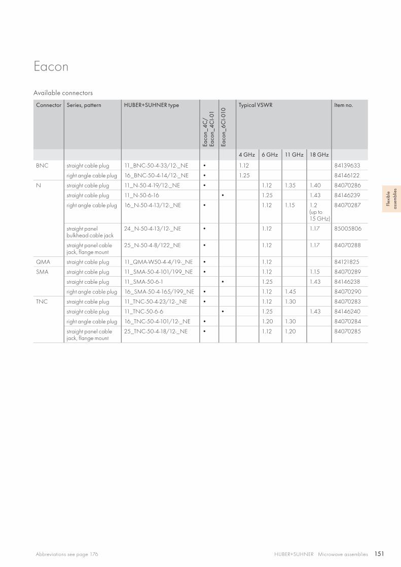
151HUBER+SUHNER Microwave assembliesAbbreviations see page 176
Flex
ible
as
sem
blie
s
Eacon
Available connectors
Connector Series, pattern HUBER+SUHNER type
Eaco
n_4C
/ Ea
con_
4CI-0
1
Eaco
n_6
CI-0
10
Typical VSWR Item no.
4 GHz 6 GHz 11 GHz 18 GHz
BNC straight cable plug 11_BNC-50-4-33/12-_NE • 1.12 84139633
right angle cable plug 16_BNC-50-4-14/12-_NE • 1.25 84146122
N straight cable plug 11_N-50-4-19/12-_NE • 1.12 1.35 1.40 84070286
straight cable plug 11_N-50-6-16 • 1.25 1.43 84146239
right angle cable plug 16_N-50-4-13/12-_NE • 1.12 1.15 1.2(up to15 GHz)
84070287
straight panel bulkhead cable jack
24_N-50-4-13/12-_NE • 1.12 1.17 85005806
straight panel cable jack, flange mount
25_N-50-4-8/122_NE • 1.12 1.17 84070288
QMA straight cable plug 11_QMA-W50-4-4/19-_NE • 1.12 84121825
SMA straight cable plug 11_SMA-50-4-101/199_NE • 1.12 1.15 84070289
straight cable plug 11_SMA-50-6-1 • 1.25 1.43 84146238
right angle cable plug 16_SMA-50-4-165/199_NE • 1.12 1.45 84070290
TNC straight cable plug 11_TNC-50-4-23/12-_NE • 1.12 1.30 84070283
straight cable plug 11_TNC-50-6-6 • 1.25 1.43 84146240
right angle cable plug 16_TNC-50-4-101/12-_NE • 1.20 1.30 84070284
straight panel cable jack, flange mount
25_TNC-50-4-18/12-_NE • 1.12 1.20 84070285
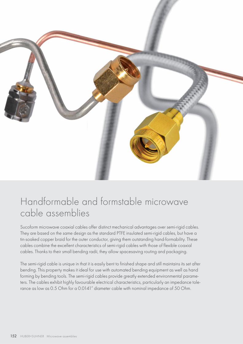
152 HUBER+SUHNER Microwave assemblies
Handformable and formstable microwavecable assemblies Sucoform microwave coaxial cables offer distinct mechanical advantages over semi-rigid cables. They are based on the same design as the standard PTFE insulated semi-rigid cables, but have a tin-soaked copper braid for the outer conductor, giving them outstanding hand-formability. These cables combine the excellent characteristics of semi-rigid cables with those of flexible coaxial cables. Thanks to their small bending radii, they allow spacesaving routing and packaging.
The semi-rigid cable is unique in that it is easily bent to finished shape and still maintains its set after bending. This property makes it ideal for use with automated bending equipment as well as hand forming by bending tools. The semi-rigid cables provide greatly extended environmental parame-ters. The cables exhibit highly favourable electrical characteristics, particularly an impedance tole-rance as low as 0.5 Ohm for a 0.0141“ diameter cable with nominal impedance of 50 Ohm.
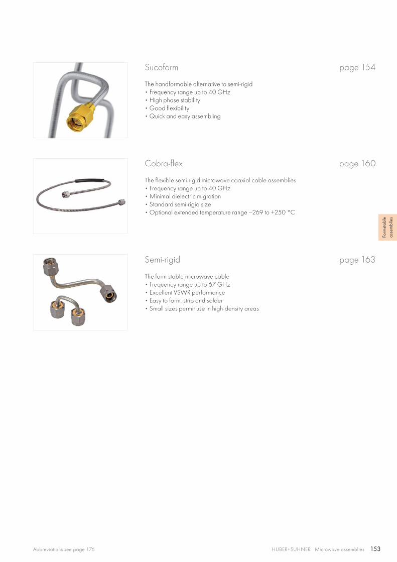
153HUBER+SUHNER Microwave assembliesAbbreviations see page 176
Form
stab
le
asse
mbl
ies
Cobra-flex page 160
The flexible semi-rigid microwave coaxial cable assemblies• Frequency range up to 40 GHz • Minimal dielectric migration• Standard semi-rigid size • Optional extended temperature range −269 to +250 °C
Semi-rigid page 163
The form stable microwave cable• Frequency range up to 67 GHz • Excellent VSWR performance• Easy to form, strip and solder• Small sizes permit use in high-density areas
Sucoform page 154
The handformable alternative to semi-rigid • Frequency range up to 40 GHz • High phase stability• Good flexibility • Quick and easy assembling
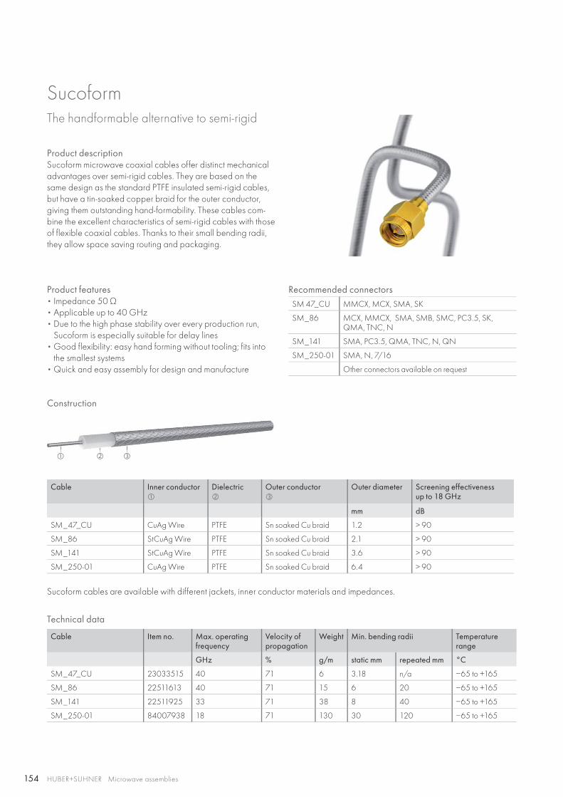
154
HUBER+SUHNER Microwave assemblies
Sucoform The handformable alternative to semi-rigid
Product descriptionSucoform microwave coaxial cables offer distinct mechanical advantages over semi-rigid cables. They are based on the same design as the standard PTFE insulated semi-rigid cables, but have a tin-soaked copper braid for the outer conductor, giving them outstanding hand-formability. These cables com-bine the excellent characteristics of semi-rigid cables with those of flexible coaxial cables. Thanks to their small bending radii, they allow space saving routing and packaging.
Product features• Impedance 50 Ω• Applicable up to 40 GHz• Due to the high phase stability over every production run,
Sucoform is especially suitable for delay lines• Good flexibility: easy hand forming without tooling; fits into
the smallest systems• Quick and easy assembly for design and manufacture
Technical data
Cable Item no. Max. operating frequency
Velocity ofpropagation
Weight Min. bending radii Temperature range
GHz % g/m static mm repeated mm °C
SM_47_CU 23033515 40 71 6 3.18 n/a −65 to +165
SM_86 22511613 40 71 15 6 20 −65 to +165
SM_141 22511925 33 71 38 8 40 −65 to +165
SM_250-01 84007938 18 71 130 30 120 −65 to +165
Recommended connectorsSM 47_CU MMCX, MCX, SMA, SK
SM_86 MCX, MMCX, SMA, SMB, SMC, PC3.5, SK, QMA, TNC, N
SM_141 SMA, PC3.5, QMA, TNC, N, QN
SM_250-01 SMA, N, 7/16
Other connectors available on request
Cable Inner conductor
Dielectric
Outer conductor
Outer diameter Screening effectivenessup to 18 GHz
mm dB
SM_47_CU CuAg Wire PTFE Sn soaked Cu braid 1.2 > 90
SM_86 StCuAg Wire PTFE Sn soaked Cu braid 2.1 > 90
SM_141 StCuAg Wire PTFE Sn soaked Cu braid 3.6 > 90
SM_250-01 CuAg Wire PTFE Sn soaked Cu braid 6.4 > 90
Sucoform cables are available with different jackets, inner conductor materials and impedances.
Construction
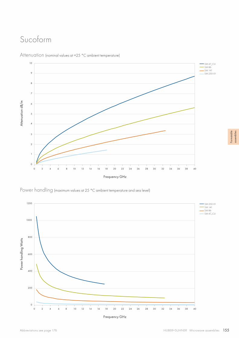
155
0 2 4 6 8 10 12 14 16 18 20 22 24 26 28 30 32 34 36 38 40
0 2 4 6 8 10 12 14 16 18 20 22 24 26 28 30 32 34 36 38 40
7
8
9
10
6
5
4
400
600
800
1000
1200
3
2
1
200
0
0
SM 47_CUSM 86SM 141SM 250-01
SM 250-01SM 141SM 86SM 47_CU
HUBER+SUHNER Microwave assembliesAbbreviations see page 176
Form
stab
le
asse
mbl
ies
Sucoform
Attenuation (nominal values at +25 °C ambient temperature)
Power handling (maximum values at 25 °C ambient temperature and sea level)
Atte
nuat
ion
dB/m
Pow
er h
andl
ing
Wat
ts
Frequency GHz
Frequency GHz

156
HUBER+SUHNER Microwave assemblies
Sucoform – with protective jacket
Technical data
Cable Item no. Max. operating frequency
Velocity ofpropagation
Weight Min. bending radii Temperature range
GHz % g/m static mm repeated mm °C
SM_47_CU_LSFH 23035506 40 71 7 4 n/a −40 to +85
SM_86_PE 22511631 40 71 19 6 20 −40 to +85
SM_86_FEP 22511942 40 71 18 6 20 −65 to +165
SM_141_CU_PE 22511639 33 71 47 8 40 −40 to +85
SM_141_CU_FEP 22512256 33 71 47 8 40 −65 to +165
SM_250-01_FEP 84007941 18 71 138 30 120 −65 to +165
Cable Inner conductor
Dielectric
Outer conductor
Jacket
Outer diameter Screeningeffectivenessup to 18 GHz
mm dB
SM_47_CU_LSFH CuAg Wire PTFE Sn soaked Cu braid LSFH 1.7 > 90
SM_86_PE StCuAg Wire PTFE Sn soaked Cu braid PE 3.2 > 90
SM_86_FEP StCuAg Wire PTFE Sn soaked Cu braid FEP 2.5 > 90
SM_141_CU_PE CuAg Wire PTFE Sn soaked Cu braid PE 4.6 > 90
SM_141_CU_FEP CuAg Wire PTFE Sn soaked Cu braid FEP 4.1 > 90
SM_250-01_FEP CuAg Wire PTFE Sn soaked Cu braid FEP 6.8 > 90
Sucoform cables are available with different inner conductor materials and impedances.
Construction
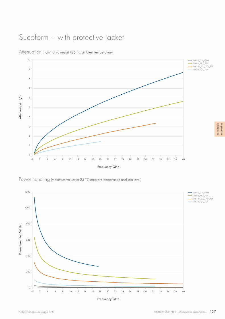
157
0 2 4 6 8 10 12 14 16 18 20 22 24 26 28 30 32 34 36 38 40
0 2 4 6 8 10 12 14 16 18 20 22 24 26 28 30 32 34 36 38 40
7
8
9
10
6
5
4
400
600
800
1000
1200
3
2
1
200
0
0
SM 47_CU_LSFHSM 86_PE/_FEPSM 141_CU_PE/_FEPSM 250-01_FEP
SM 47_CU_LSFHSM 86_PE/_FEPSM 141_CU_PE/_FEPSM 250-01_FEP
HUBER+SUHNER Microwave assembliesAbbreviations see page 176
Form
stab
le
asse
mbl
ies
Sucoform – with protective jacket
Attenuation (nominal values at +25 °C ambient temperature)
Power handling (maximum values at 25 °C ambient temperature and sea level)
Atte
nuat
ion
dB/m
Pow
er h
andl
ing
Wat
ts
Frequency GHz
Frequency GHz
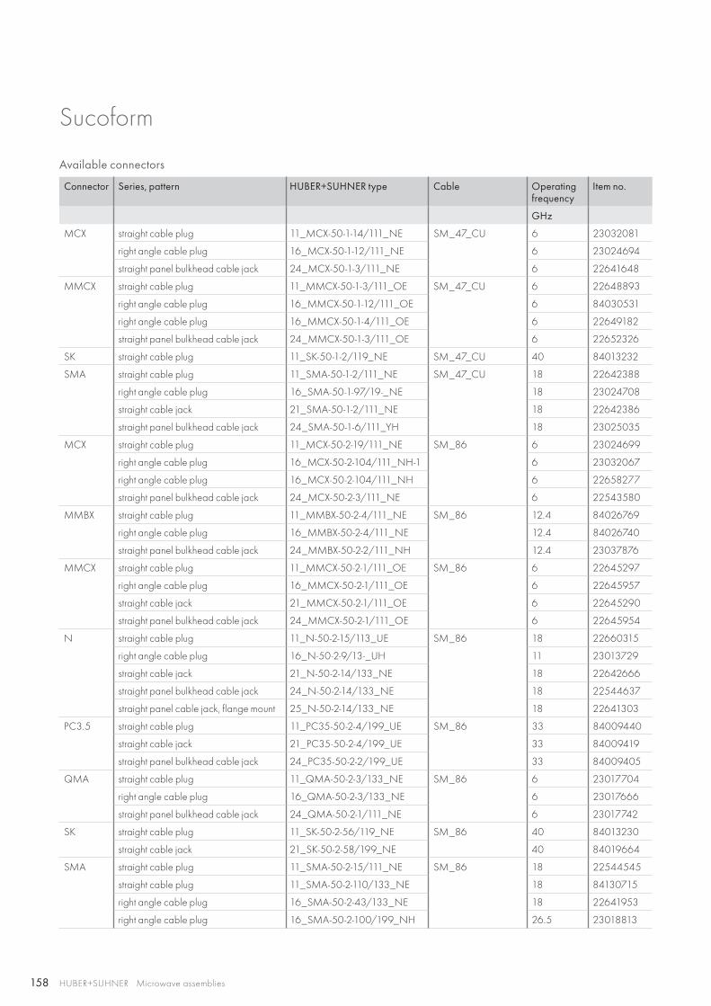
158 HUBER+SUHNER Microwave assemblies
Sucoform
Available connectors
Connector Series, pattern HUBER+SUHNER type Cable Operating frequency
Item no.
GHz
MCX straight cable plug 11_MCX-50-1-14/111_NE SM_47_CU 6 23032081
right angle cable plug 16_MCX-50-1-12/111_NE 6 23024694
straight panel bulkhead cable jack 24_MCX-50-1-3/111_NE 6 22641648
MMCX straight cable plug 11_MMCX-50-1-3/111_OE SM_47_CU 6 22648893
right angle cable plug 16_MMCX-50-1-12/111_OE 6 84030531
right angle cable plug 16_MMCX-50-1-4/111_OE 6 22649182
straight panel bulkhead cable jack 24_MMCX-50-1-3/111_OE 6 22652326
SK straight cable plug 11_SK-50-1-2/119_NE SM_47_CU 40 84013232
SMA straight cable plug 11_SMA-50-1-2/111_NE SM_47_CU 18 22642388
right angle cable plug 16_SMA-50-1-97/19-_NE 18 23024708
straight cable jack 21_SMA-50-1-2/111_NE 18 22642386
straight panel bulkhead cable jack 24_SMA-50-1-6/111_YH 18 23025035
MCX straight cable plug 11_MCX-50-2-19/111_NE SM_86 6 23024699
right angle cable plug 16_MCX-50-2-104/111_NH-1 6 23032067
right angle cable plug 16_MCX-50-2-104/111_NH 6 22658277
straight panel bulkhead cable jack 24_MCX-50-2-3/111_NE 6 22543580
MMBX straight cable plug 11_MMBX-50-2-4/111_NE SM_86 12.4 84026769
right angle cable plug 16_MMBX-50-2-4/111_NE 12.4 84026740
straight panel bulkhead cable jack 24_MMBX-50-2-2/111_NH 12.4 23037876
MMCX straight cable plug 11_MMCX-50-2-1/111_OE SM_86 6 22645297
right angle cable plug 16_MMCX-50-2-1/111_OE 6 22645957
straight cable jack 21_MMCX-50-2-1/111_OE 6 22645290
straight panel bulkhead cable jack 24_MMCX-50-2-1/111_OE 6 22645954
N straight cable plug 11_N-50-2-15/113_UE SM_86 18 22660315
right angle cable plug 16_N-50-2-9/13-_UH 11 23013729
straight cable jack 21_N-50-2-14/133_NE 18 22642666
straight panel bulkhead cable jack 24_N-50-2-14/133_NE 18 22544637
straight panel cable jack, flange mount 25_N-50-2-14/133_NE 18 22641303
PC3.5 straight cable plug 11_PC35-50-2-4/199_UE SM_86 33 84009440
straight cable jack 21_PC35-50-2-4/199_UE 33 84009419
straight panel bulkhead cable jack 24_PC35-50-2-2/199_UE 33 84009405
QMA straight cable plug 11_QMA-50-2-3/133_NE SM_86 6 23017704
right angle cable plug 16_QMA-50-2-3/133_NE 6 23017666
straight panel bulkhead cable jack 24_QMA-50-2-1/111_NE 6 23017742
SK straight cable plug 11_SK-50-2-56/119_NE SM_86 40 84013230
straight cable jack 21_SK-50-2-58/199_NE 40 84019664
SMA straight cable plug 11_SMA-50-2-15/111_NE SM_86 18 22544545
straight cable plug 11_SMA-50-2-110/133_NE 18 84130715
right angle cable plug 16_SMA-50-2-43/133_NE 18 22641953
right angle cable plug 16_SMA-50-2-100/199_NH 26.5 23018813

159HUBER+SUHNER Microwave assembliesAbbreviations see page 176
Form
stab
le
asse
mbl
ies
Sucoform
Connector Series, pattern HUBER+SUHNER type Cable Operating frequency
Item no.
GHz
SMA straight cable jack 21_SMA-50-2-15/111_NE SM_86 18 22544549
straight panel bulkhead cable jack 24_SMA-50-2-15/111_NE 18 22544532
straight panel bulkhead cable jack 24_SMA-50-2-41/133_NE 18 22641381
SMB straight cable plug 11_SMB-50-2-13/111_NE SM_86 4 22543362
right angle cable plug 16_SMB-50-2-23/111_NE 4 22644079
straight panel bulkhead cable jack 24_SMB-50-2-13/111_NE 4 22640822
SMC straight cable plug 11_SMC-50-2-13/111_NE SM_86 10 22543363
right angle cable plug 16_SMC-50-2-25/111_NE 10 22644126
straight panel bulkhead cable jack 24_SMC-50-2-13/111_NE 10 22640297
TNC straight cable plug 11_TNC-50-2-20/103_NE SM_86 11 22642519
straight panel bulkhead cable jack 24_TNC-50-2-31/133_NE 11 23001721
N straight cable plug 11_N-50-3-13/113_NE SM_141 11 22542083
straight cable plug 11_N-50-3-51/133_NE 18 22543919
right angle cable plug 16_N-50-3-15/133_NE 11 22648832
straight cable jack 21_N-50-3-51/19-_NE 18 22543922
straight panel bulkhead cable jack 24_N-50-3-51/19-_NE 18 22642344
straight panel cable jack, flange mount 25_N-50-3-9/133_NE 11 22543952
PC3.5 straight cable plug 11_PC35-50-3-4/199_UE SM_141 33 84009380
straight cable jack 21_PC35-50-3-3/199_UE 33 84009382
straight panel bulkhead cable jack 24_PC35-50-3-2/199_UE 33 84009383
QMA straight cable plug 11_QMA-50-3-3/133_NE SM_141 6 23017695
right angle cable plug 16_QMA-50-3-3/133_NE 6 23017693
straight panel bulkhead cable jack 24_QMA-50-3-3/111_NE 6 23017683
QN straight cable plug 11_QN-50-3-3/113_NE SM_141 11 23033393
right angle cable plug 16_QN-50-3-3/13-_NE 11 23033268
straight panel bulkhead cable jack 24_QN-50-3-3/13-_NE 11 23033423
SMA straight cable plug 11_SMA-50-3-77/119_NH EZ_141 18 84005524
straight cable plug 11_SMA-50-3-235/133_NE 18 84130698
right angle cable plug 16_SMA-50-3-3/111_NE 18 22640073
right angle cable plug 16_SMA-50-3-13/133_NE 18 84130707
straight cable jack 21_SMA-50-3-15/111_NE 18 22544550
straight panel bulkhead cable jack 24_SMA-50-3-15/111_NE 18 22641153
TNC straight cable plug 11_TNC-50-3-29/103_NE EZ_141 11 22641997
right angle cable plug 16_TNC-50-3-24/13-_NE 11 84021420
straight panel bulkhead cable jack 24_TNC-50-3-30/133_NH 11 23001723
7/16 straight cable plug 11_716-50-5-6/003_Y SM_250-01 7.5 84008435
straight panel cable jack, flange mount 25_716-50-5-17/000_Y 7.5 84008881
N straight cable plug 11_N-50-5-18/103_NH SM_250-01 11 84008445
right angle cable plug 16_N-50-5-7/13-_-H 7.5 21000191
SMA straight cable plug 11_SMA-50-5-1/111_NE SM_250-01 18 22642399

160
HUBER+SUHNER Microwave assemblies
Cobra-flexThe flexible semi-rigid microwave coaxial cable assemblies
Product descriptioncobra-flex is high performance semi-rigid cables which utilise a seamless outer conductor to provide excellent RF shielding. The convoluted design gives this cable excellent phase track-ing characteristics over temperature due to minimal dielectric migration. These cables are offered with many options includ-ing tin-plated outer conductor, copper clad steel center con-ductor for low thermal conductivity in cryogenic applications.
Product features• Impedance 50 Ω• Applicable up to 40 GHz • Minimal dielectric migration• Higher flexibility without outer conductor fatiguing• Standard semi-rigid sizes• Optional extended temperature range −269 to +250 °C
for cryogenic applications
Technical data
Cable Item no. Replacement for
Max. operating frequency
Velocity of propagation
Weight Min. bending radii Temperature range
GHz % g/m static mm repeated mm °C
31000 80310897 RG_402 32 70.3 35.7 19.1 57.2 −55 to +200
31000S 80320630 32 70.3 35.7 19.1 57.2
31086 80310901 RG_405 40 70.3 20.8 8.9 26.7
Construction
Cable Inner conductor
Dielectric
Outer conductor
Outer diameter
mm
31000 CuAg wire PTFE StCu tube 3.6
31000S StCuAg wire PTFE StCu tube 3.6
31086 CuAg wire PTFE StCu tube 2.2
Recommended connectors31086 SMA, SK, 3.5 mm, TNC, N
31000 SMA, TNC, N, 3.5 mm
31000S SMA, TNC, N, 3.5 mm
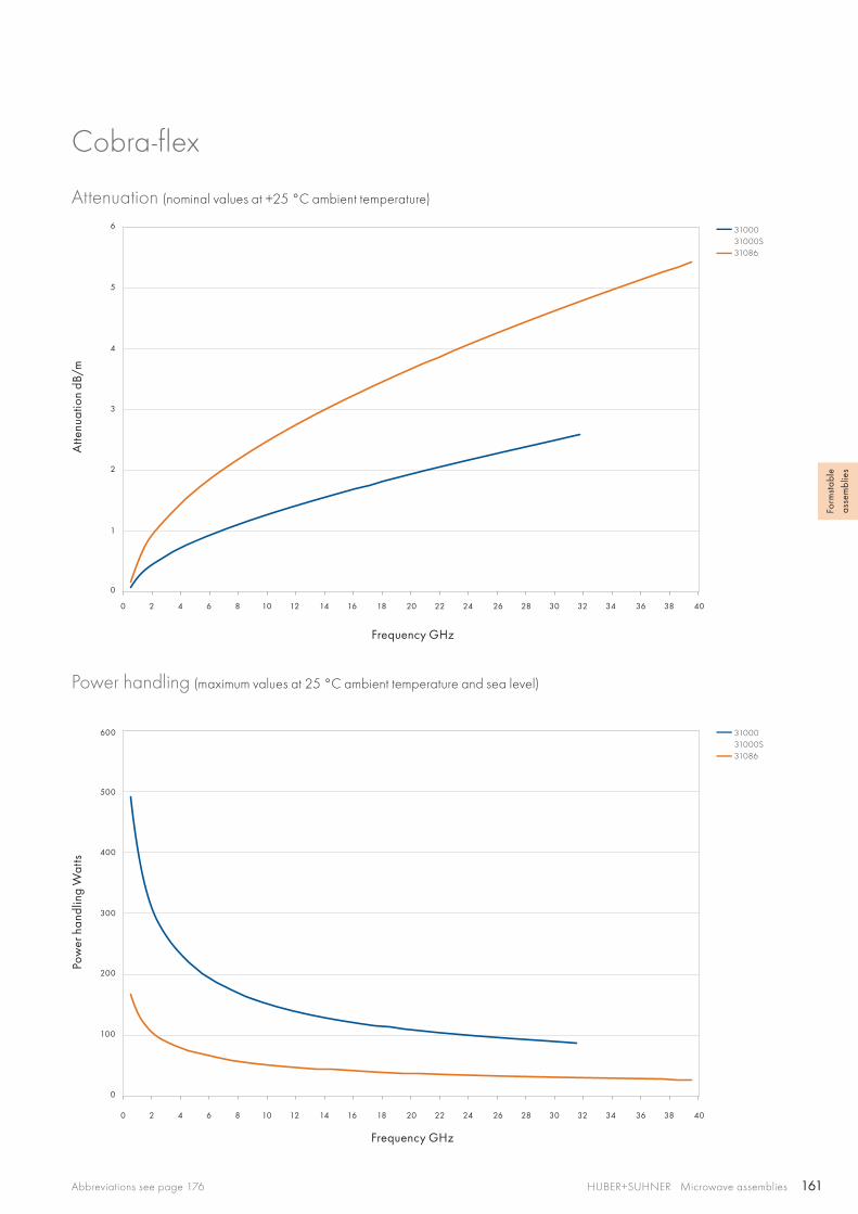
161
0 2 4 6 8 10 12 14 16 18 20 22 24 26 28 30 32 34 36 38 40
0 2 4 6 8 10 12 14 16 18 20 22 24 26 28 30 32 34 36 38 40
6
5
4
200
300
400
500
600
3
2
1
100
0
0
3100031000S 31086
3100031000S31086
HUBER+SUHNER Microwave assembliesAbbreviations see page 176
Form
stab
le
asse
mbl
ies
Cobra-flex
Attenuation (nominal values at +25 °C ambient temperature)
Power handling (maximum values at 25 °C ambient temperature and sea level)
Atte
nuat
ion
dB/m
Pow
er h
andl
ing
Wat
ts
Frequency GHz
Frequency GHz
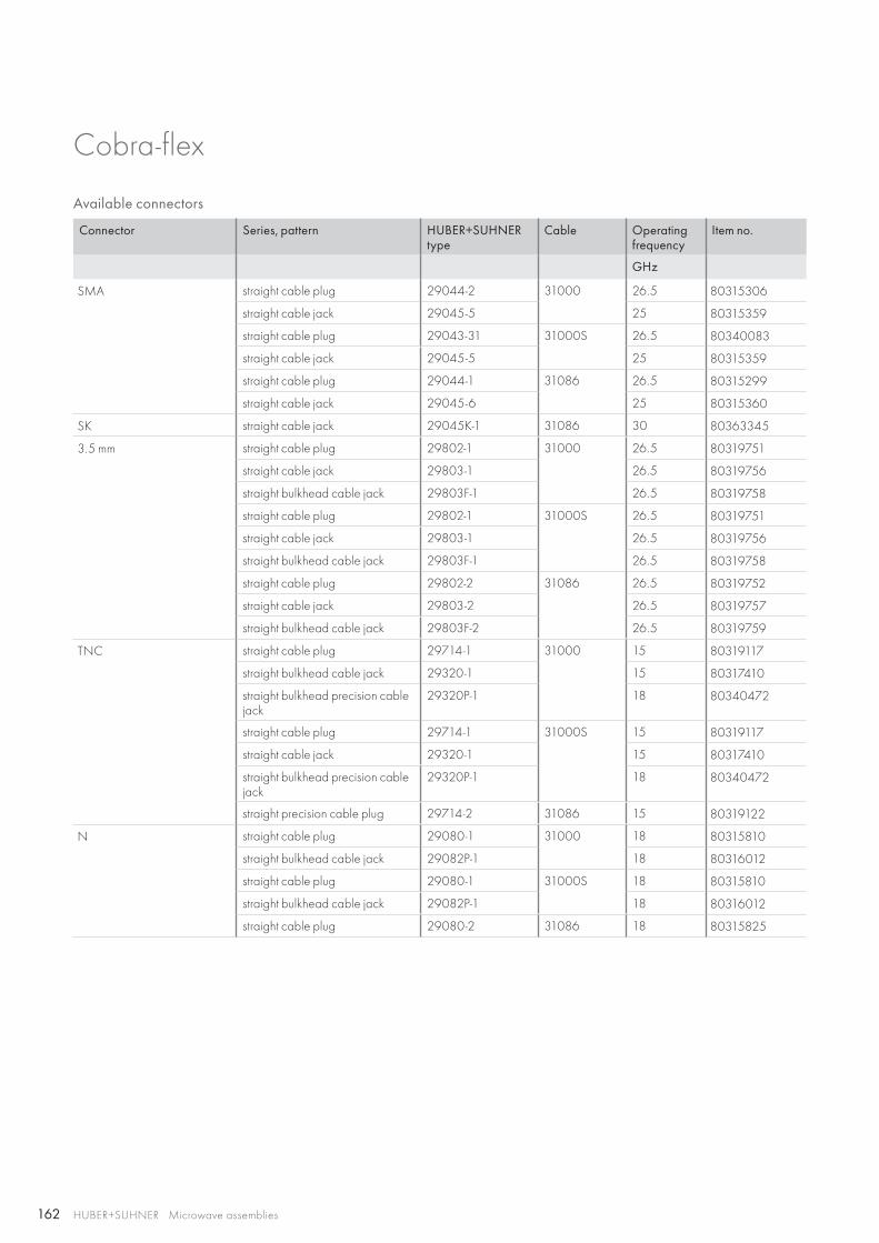
162 HUBER+SUHNER Microwave assemblies
Available connectors
Connector Series, pattern HUBER+SUHNER type
Cable Operating frequency
Item no.
GHz
SMA straight cable plug 29044-2 31000 26.5 80315306
straight cable jack 29045-5 25 80315359
straight cable plug 29043-31 31000S 26.5 80340083
straight cable jack 29045-5 25 80315359
straight cable plug 29044-1 31086 26.5 80315299
straight cable jack 29045-6 25 80315360
SK straight cable jack 29045K-1 31086 30 80363345
3.5 mm straight cable plug 29802-1 31000 26.5 80319751
straight cable jack 29803-1 26.5 80319756
straight bulkhead cable jack 29803F-1 26.5 80319758
straight cable plug 29802-1 31000S 26.5 80319751
straight cable jack 29803-1 26.5 80319756
straight bulkhead cable jack 29803F-1 26.5 80319758
straight cable plug 29802-2 31086 26.5 80319752
straight cable jack 29803-2 26.5 80319757
straight bulkhead cable jack 29803F-2 26.5 80319759
TNC straight cable plug 29714-1 31000 15 80319117
straight bulkhead cable jack 29320-1 15 80317410
straight bulkhead precision cable jack
29320P-1 18 80340472
straight cable plug 29714-1 31000S 15 80319117
straight cable jack 29320-1 15 80317410
straight bulkhead precision cable jack
29320P-1 18 80340472
straight precision cable plug 29714-2 31086 15 80319122
N straight cable plug 29080-1 31000 18 80315810
straight bulkhead cable jack 29082P-1 18 80316012
straight cable plug 29080-1 31000S 18 80315810
straight bulkhead cable jack 29082P-1 18 80316012
straight cable plug 29080-2 31086 18 80315825
Cobra-flex
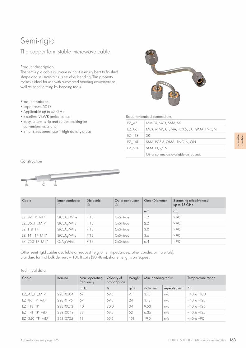
163
HUBER+SUHNER Microwave assembliesAbbreviations see page 176
Form
stab
le
asse
mbl
ies
Semi-rigidThe copper form stable microwave cable
Product descriptionThe semi-rigid cable is unique in that it is easily bent to finished shape and still maintains its set after bending. This property makes it ideal for use with automated bending equipment as well as hand forming by bending tools.
Product features• Impedance 50 Ω• Applicable up to 67 GHz• Excellent VSWR performance• Easy to form, strip and solder, making for
convenient installation• Small sizes permit use in high-density areas
Recommended connectors
EZ_47 MMCX, MCX, SMA, SK
EZ_86 MCX, MMCX, SMA, PC3.5, SK, QMA, TNC, N
EZ_118 SK
EZ_141 SMA, PC3.5, QMA, TNC, N, QN
EZ_250 SMA, N, 7/16
Other connectors available on request.
Technical data
Cable Item no. Max. operating frequency
Velocity ofpropagation
Weight Min. bending radius Temperature range
GHz % g/m static mm repeated mm °C
EZ_47_TP_M17 22810504 67 69.5 7.1 3.18 n/a −40 to +100
EZ_86_TP_M17 22810175 67 69.5 24 3.18 n/a −40 to +125
EZ_118_TP 22810073 40 80.0 34 9.53 n/a −40 to +125
EZ_141_TP_M17 22810043 33 69.5 52 6.35 n/a −40 to +125
EZ_250_TP_M17 22810705 18 69.5 158 19.0 n/a −40 to +90
Cable Inner conductor
Dielectric
Outer conductor
Outer Diameter Screening effectivenessup to 18 GHz
mm dB
EZ_47_TP_M17 StCuAg Wire PTFE CuSn tube 1.2 > 90
EZ_86_TP_M17 StCuAg Wire PTFE CuSn tube 2.2 > 90
EZ_118_TP StCuAg Wire PTFE CuSn tube 3.0 > 90
EZ_141_TP_M17 StCuAg Wire PTFE CuSn tube 3.6 > 90
EZ_250_TP_M17 CuAg Wire PTFE CuSn tube 6.4 > 90
Other semi rigid cables available on request (e.g. other impedances, other conductor materials).Standard form of bulk delivery = 100 ft coils (30.48 m), shorter lengths on request.
Construction

164
HUBER+SUHNER Microwave assemblies
Semi-rigidThe aluminium form stable microwave cable
Product descriptionThe semi-rigid cable is unique in that it is easily bent to finished shape and still maintains its set after bending. This property makes it ideal for use with automated bending equipment as well as hand forming by bending tools.
Product features• Impedance 50 Ω• Applicable up to 67 GHz• Excellent VSWR performance• Easy to form, strip and solder, making for
convenient installation• Small sizes permit use in high-density areas
Recommended connectors
EZ_47 MMCX, MCX, SMA, SK
EZ_86 MCX, MMCX, SMA, PC3.5, SK, QMA, TNC, N
EZ_118 SK
EZ_141 SMA, PC3.5, QMA, TNC, N, QN
EZ_250 SMA, N, 7/16
Other connectors available on request.
Technical data
Cable Item no. Max. operating frequency
Velocity ofpropagation
Weight Min. bending radius Temperature range
GHz % g/m static mm repeated mm °C
EZ_47_AL_TP_M17 22810510 67 69.5 3.1 1.27 n/a −40 to +100
EZ_86_AL_TP_M17 22810167 67 69.5 11.9 1.78 n/a −40 to +125
EZ_141_AL_TP_M17 22810015 33 69.5 30.5 3.18 n/a −40 to +125
EZ_250_AL_TP_M17 22810708 18 69.5 88.6 19.0 n/a −40 to +90
Cable Inner conductor
Dielectric
Outer conductor
Outer diameter Screening effectivenessup to 18 GHz
mm dB
EZ_47_AL_TP_M17 StCuAg Wire PTFE AlSn tube 1.2 > 90
EZ_86_AL_TP_M17 StCuAg Wire PTFE AlSn tube 2.2 > 90
EZ_141_AL_TP_M17 StCuAg Wire PTFE AISn tube 3.6 > 90
EZ_250_AL_TP_M17 CuAg Wire PTFE AISn tube 6.4 > 90
Other semi rigid cables available on request (e.g. other impedances, other conductor materials).Standard form of bulk delivery = 100 ft coils (30.48 m), shorter lengths on request.
Construction
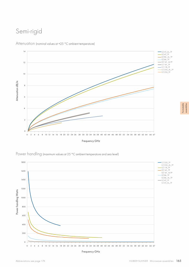
165
0 2 4 6 8 10 12 14 16 18 20 22 24 26 28 30 32 34 36 38 40 42 44 46 48 50 52 54 56 58 60 62 64 66 67
10
14
12
2
4
6
8
0
0
200
400
600
800
1000
1200
1400
1600
1800
0 2 4 6 8 10 12 14 16 18 20 22 24 26 28 30 32 34 36 38 40 42 44 46 48 50 52 54 56 58 60 62 64 66 67
EZ 47_AL_TPEZ 47_TPEZ 86_AL_TPEZ 86_TPEZ 141_AL-TPEZ 141_TPEZ 118_TPEZ 250_AL_TPEZ 250_TP
EZ 250_TPEZ 250_AL_TPEZ 118_TPEZ 141_TPEZ 141_AL-TPEZ 86_TPEZ 86_AL_TPEZ 47_TPEZ 47_AL_TP
HUBER+SUHNER Microwave assembliesAbbreviations see page 176
Form
stab
le
asse
mbl
ies
Semi-rigid
Attenuation (nominal values at +25 °C ambient temperature)
Power handling (maximum values at 25 °C ambient temperature and sea level)
Atte
nuat
ion
dB/m
Pow
er h
andl
ing
Wat
ts
Frequency GHz
Frequency GHz
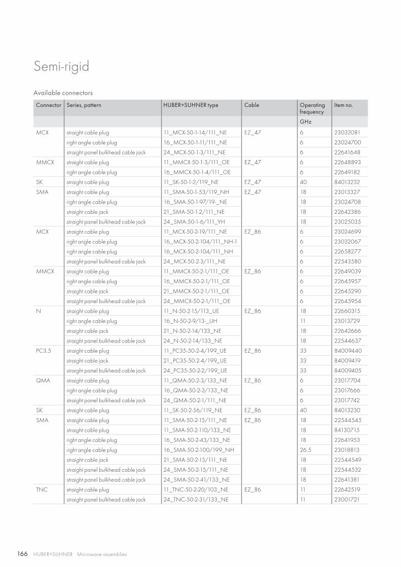
166 HUBER+SUHNER Microwave assemblies
Semi-rigid
Available connectors
Connector Series, pattern HUBER+SUHNER type Cable Operating frequency
Item no.
GHz
MCX straight cable plug 11_MCX-50-1-14/111_NE EZ_47 6 23032081
right angle cable plug 16_MCX-50-1-11/111_NE 6 23024700
straight panel bulkhead cable jack 24_MCX-50-1-3/111_NE 6 22641648
MMCX straight cable plug 11_MMCX-50-1-3/111_OE EZ_47 6 22648893
right angle cable plug 16_MMCX-50-1-4/111_OE 6 22649182
SK straight cable plug 11_SK-50-1-2/119_NE EZ_47 40 84013232
SMA straight cable plug 11_SMA-50-1-53/119_NH EZ_47 18 23013327
right angle cable plug 16_SMA-50-1-97/19-_NE 18 23024708
straight cable jack 21_SMA-50-1-2/111_NE 18 22642386
straight panel bulkhead cable jack 24_SMA-50-1-6/111_YH 18 23025035
MCX straight cable plug 11_MCX-50-2-19/111_NE EZ_86 6 23024699
right angle cable plug 16_MCX-50-2-104/111_NH-1 6 23032067
right angle cable plug 16_MCX-50-2-104/111_NH 6 22658277
straight panel bulkhead cable jack 24_MCX-50-2-3/111_NE 6 22543580
MMCX straight cable plug 11_MMCX-50-2-1/111_OE EZ_86 6 22649039
right angle cable plug 16_MMCX-50-2-1/111_OE 6 22645957
straight cable jack 21_MMCX-50-2-1/111_OE 6 22645290
straight panel bulkhead cable jack 24_MMCX-50-2-1/111_OE 6 22645954
N straight cable plug 11_N-50-2-15/113_UE EZ_86 18 22660315
right angle cable plug 16_N-50-2-9/13-_UH 11 23013729
straight cable jack 21_N-50-2-14/133_NE 18 22642666
straight panel bulkhead cable jack 24_N-50-2-14/133_NE 18 22544637
PC3.5 straight cable plug 11_PC35-50-2-4/199_UE EZ_86 33 84009440
straight cable jack 21_PC35-50-2-4/199_UE 33 84009419
straight panel bulkhead cable jack 24_PC35-50-2-2/199_UE 33 84009405
QMA straight cable plug 11_QMA-50-2-3/133_NE EZ_86 6 23017704
right angle cable plug 16_QMA-50-2-3/133_NE 6 23017666
straight panel bulkhead cable jack 24_QMA-50-2-1/111_NE 6 23017742
SK straight cable plug 11_SK-50-2-56/119_NE EZ_86 40 84013230
SMA straight cable plug 11_SMA-50-2-15/111_NE EZ_86 18 22544545
straight cable plug 11_SMA-50-2-110/133_NE 18 84130715
right angle cable plug 16_SMA-50-2-43/133_NE 18 22641953
right angle cable plug 16_SMA-50-2-100/199_NH 26.5 23018813
straight cable jack 21_SMA-50-2-15/111_NE 18 22544549
straight panel bulkhead cable jack 24_SMA-50-2-15/111_NE 18 22544532
straight panel bulkhead cable jack 24_SMA-50-2-41/133_NE 18 22641381
TNC straight cable plug 11_TNC-50-2-20/103_NE EZ_86 11 22642519
straight panel bulkhead cable jack 24_TNC-50-2-31/133_NE 11 23001721
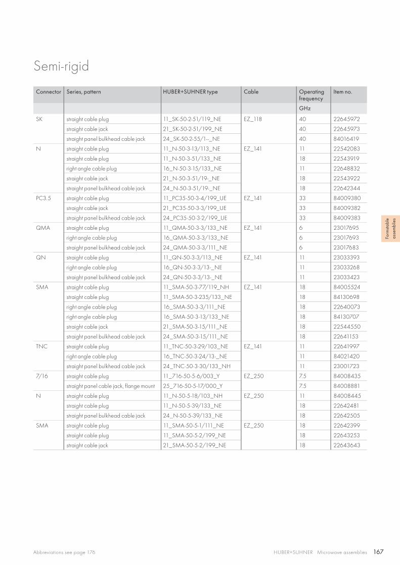
167HUBER+SUHNER Microwave assembliesAbbreviations see page 176
Form
stab
le
asse
mbl
ies
Semi-rigid
Connector Series, pattern HUBER+SUHNER type Cable Operating frequency
Item no.
GHz
SK straight cable plug 11_SK-50-2-51/119_NE EZ_118 40 22645972
straight cable jack 21_SK-50-2-51/199_NE 40 22645973
straight panel bulkhead cable jack 24_SK-50-2-55/1--_NE 40 84016419
N straight cable plug 11_N-50-3-13/113_NE EZ_141 11 22542083
straight cable plug 11_N-50-3-51/133_NE 18 22543919
right angle cable plug 16_N-50-3-15/133_NE 11 22648832
straight cable jack 21_N-50-3-51/19-_NE 18 22543922
straight panel bulkhead cable jack 24_N-50-3-51/19-_NE 18 22642344
PC3.5 straight cable plug 11_PC35-50-3-4/199_UE EZ_141 33 84009380
straight cable jack 21_PC35-50-3-3/199_UE 33 84009382
straight panel bulkhead cable jack 24_PC35-50-3-2/199_UE 33 84009383
QMA straight cable plug 11_QMA-50-3-3/133_NE EZ_141 6 23017695
right angle cable plug 16_QMA-50-3-3/133_NE 6 23017693
straight panel bulkhead cable jack 24_QMA-50-3-3/111_NE 6 23017683
QN straight cable plug 11_QN-50-3-3/113_NE EZ_141 11 23033393
right angle cable plug 16_QN-50-3-3/13-_NE 11 23033268
straight panel bulkhead cable jack 24_QN-50-3-3/13-_NE 11 23033423
SMA straight cable plug 11_SMA-50-3-77/119_NH EZ_141 18 84005524
straight cable plug 11_SMA-50-3-235/133_NE 18 84130698
right angle cable plug 16_SMA-50-3-3/111_NE 18 22640073
right angle cable plug 16_SMA-50-3-13/133_NE 18 84130707
straight cable jack 21_SMA-50-3-15/111_NE 18 22544550
straight panel bulkhead cable jack 24_SMA-50-3-15/111_NE 18 22641153
TNC straight cable plug 11_TNC-50-3-29/103_NE EZ_141 11 22641997
right angle cable plug 16_TNC-50-3-24/13-_NE 11 84021420
straight panel bulkhead cable jack 24_TNC-50-3-30/133_NH 11 23001723
7/16 straight cable plug 11_716-50-5-6/003_Y EZ_250 7.5 84008435
straight panel cable jack, flange mount 25_716-50-5-17/000_Y 7.5 84008881
N straight cable plug 11_N-50-5-18/103_NH EZ_250 11 84008445
straight cable plug 11_N-50-5-39/133_NE 18 22642481
straight panel bulkhead cable jack 24_N-50-5-39/133_NE 18 22642505
SMA straight cable plug 11_SMA-50-5-1/111_NE EZ_250 18 22642399
straight cable plug 11_SMA-50-5-2/199_NE 18 22643253
straight cable jack 21_SMA-50-5-2/199_NE 18 22643643
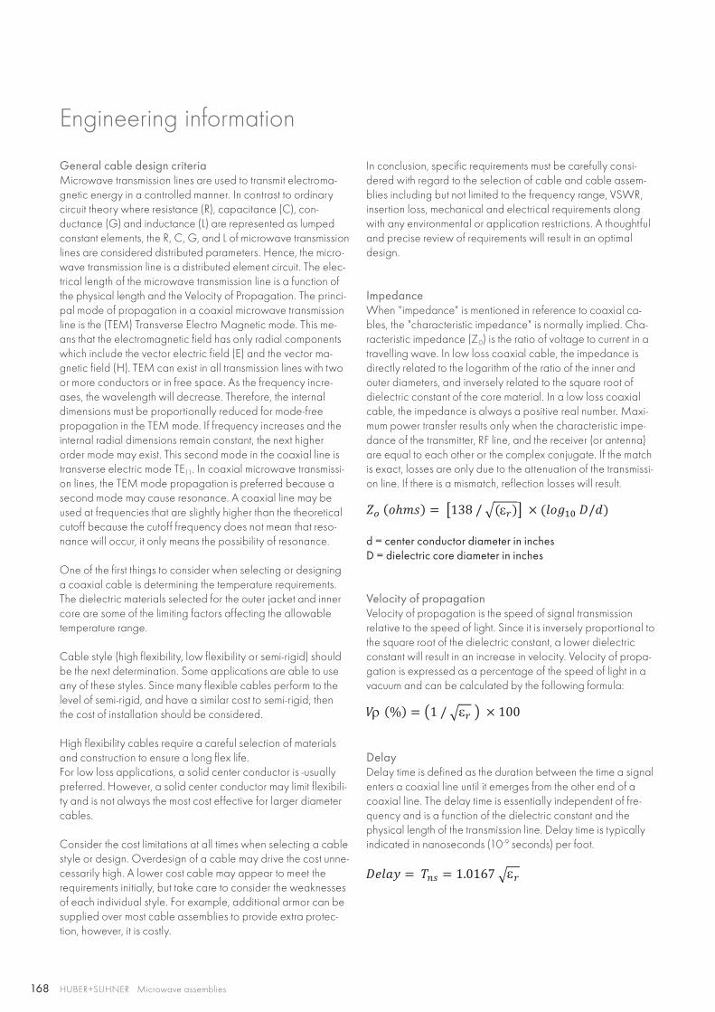
168
ε
% ερ
ε
HUBER+SUHNER Microwave assemblies
Engineering information
General cable design criteriaMicrowave transmission lines are used to transmit electroma-gnetic energy in a controlled manner. In contrast to ordinary circuit theory where resistance (R), capacitance (C), con-ductance (G) and inductance (L) are represented as lumped constant elements, the R, C, G, and L of microwave transmission lines are considered distributed parameters. Hence, the micro-wave transmission line is a distributed element circuit. The elec-trical length of the microwave transmission line is a function of the physical length and the Velocity of Propagation. The princi-pal mode of propagation in a coaxial microwave transmission line is the (TEM) Transverse Electro Magnetic mode. This me-ans that the electromagnetic field has only radial components which include the vector electric field (E) and the vector ma-gnetic field (H). TEM can exist in all transmission lines with two or more conductors or in free space. As the frequency incre-ases, the wavelength will decrease. Therefore, the internal dimensions must be proportionally reduced for mode-free propagation in the TEM mode. If frequency increases and the internal radial dimensions remain constant, the next higher order mode may exist. This second mode in the coaxial line is transverse electric mode TE11. In coaxial microwave transmissi-on lines, the TEM mode propagation is preferred because a second mode may cause resonance. A coaxial line may be used at frequencies that are slightly higher than the theoretical cutoff because the cutoff frequency does not mean that reso-nance will occur, it only means the possibility of resonance.
One of the first things to consider when selecting or designing a coaxial cable is determining the temperature requirements. The dielectric materials selected for the outer jacket and inner core are some of the limiting factors affecting the allowable temperature range.
Cable style (high flexibility, low flexibility or semi-rigid) should be the next determination. Some applications are able to use any of these styles. Since many flexible cables perform to the level of semi-rigid, and have a similar cost to semi-rigid, then the cost of installation should be considered.
High flexibility cables require a careful selection of materials and construction to ensure a long flex life. For low loss applications, a solid center conductor is -usually preferred. However, a solid center conductor may limit flexibili-ty and is not always the most cost effective for larger diameter cables.
Consider the cost limitations at all times when selecting a cable style or design. Overdesign of a cable may drive the cost unne-cessarily high. A lower cost cable may appear to meet the requirements initially, but take care to consider the weaknesses of each individual style. For example, additional armor can be supplied over most cable assemblies to provide extra protec-tion, however, it is costly.
In conclusion, specific requirements must be carefully consi-dered with regard to the selection of cable and cable assem-blies including but not limited to the frequency range, VSWR, insertion loss, mechanical and electrical requirements along with any environmental or application restrictions. A thoughtful and precise review of requirements will result in an optimal design.
ImpedanceWhen "impedance" is mentioned in reference to coaxial ca-bles, the "characteristic impedance" is normally implied. Cha-racteristic impedance (Z0) is the ratio of voltage to current in a travelling wave. In low loss coaxial cable, the impedance is directly related to the logarithm of the ratio of the inner and outer diameters, and inversely related to the square root of dielectric constant of the core material. In a low loss coaxial cable, the impedance is always a positive real number. Maxi-mum power transfer results only when the characteristic impe-dance of the transmitter, RF line, and the receiver (or antenna) are equal to each other or the complex conjugate. If the match is exact, losses are only due to the attenuation of the transmissi-on line. If there is a mismatch, reflection losses will result.
d = center conductor diameter in inchesD = dielectric core diameter in inches
Velocity of propagationVelocity of propagation is the speed of signal transmission relative to the speed of light. Since it is inversely proportional to the square root of the dielectric constant, a lower dielectric constant will result in an increase in velocity. Velocity of propa-gation is expressed as a percentage of the speed of light in a vacuum and can be calculated by the following formula:
DelayDelay time is defined as the duration between the time a signal enters a coaxial line until it emerges from the other end of a coaxial line. The delay time is essentially independent of fre-quency and is a function of the dielectric constant and the physical length of the transmission line. Delay time is typically indicated in nanoseconds (10-9 seconds) per foot.
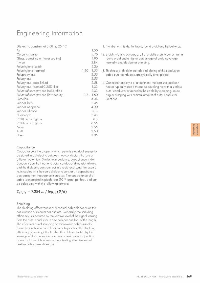
169
Engi
neer
ing
info
rmat
ion
HUBER+SUHNER Microwave assembliesAbbreviations see page 176
Engineering information
Dielectric constant at 3 GHz, 25 °CAir 1.00Ceramic steatite 5.70Glass, borosilicate (Kovar sealing) 4.90Nylon 2.84Polyethylene (solid) 2.26Polyethylene (foamed) 1.20 – 1.55Polypropylene 2.55Polystyrene 2.55Polystyrene, cross-linked 2.58Polystyrene, foamed 0.25% filler 1.03Polytetrafluoroethylene (solid teflon 2.03Polytetrafluoroethylene (low density) 1.2 – 1.60Porcelain 5.04Rubber, butyl 2.35Rubber, neoprene 4.00Rubber, silicone 3.13Fluoroloy H 2.439010 corning glass 6.39013 corning glass 6.65Noryl 2.55K-50 2.60Ultem 3.05
CapacitanceCapacitance is the property which permits electrical energy to be stored in a dielectric between two conductors that are at different potentials. Similar to impedance, capacitance is de-pendent upon the inner and outer conductor dimensional ratio and the dielectric constant, but in a reciprocal way. For examp-le, in cables with the same dielectric constant, if capacitance decreases then impedance increases. The capacitance of a cable is expressed in picofarads (10-12 farad) per foot, and can be calculated with the following formula:
ShieldingThe shielding effectiveness of a coaxial cable depends on the construction of its outer conductors. Generally, the shielding efficiency is measured by the relative level of the signal leaking from the outer conductor in decibels per one foot of the length. The effectiveness of shielding on microwave cables usually diminishes with increased frequency. In practice, the shielding efficiency of semi-rigid (solid sheath) cables is limited by the leakage of the connectors and the cable/connector junction. Some factors which influence the shielding effectiveness of flexible cable assemblies are:
1. Number of shields: flat braid, round braid and helical wrap
2. Braid style and coverage: a flat braid is usually better than a round braid and a higher percentage of braid coverage normally provides better shielding.
3. Thickness of shield materials and plating of the conductor: cable outer conductors are typically silver plated.
4. Connector and style of attachment: the best shielded con-nector typically uses a threaded coupling nut with a slotless outer conductor attached to the cable by clamping, solde-ring or crimping with minimal amount of outer conductor junctions.
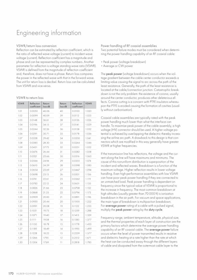
170 HUBER+SUHNER Microwave assemblies
VSWR/return loss conversionReflection can be estimated by reflection coefficient, which is the ratio of reflected wave voltage (current) to incident wave voltage (current). Reflection coefficient has a magnitude and phase and can be represented by complex numbers. Another parameter for reflection is voltage standing wave ratio (VSWR). VSWR is defined from the magnitude of reflection coefficient and, therefore, does not have a phase. Return loss compares the power in the reflected wave with that in the forward wave. The unit for return loss is decibel. Return loss can be calculated from VSWR and vice-versa.
VSWR to return loss
VSWR Reflection coefficient
Return loss dB
Return loss dB
Reflection coefficient
VSWR
1.01 0.0050 46.06 40 0.0100 1.020
1.02 0.0099 40.09 39 0.0112 1.023
1.03 0.0148 36.61 38 0.0126 1.026
1.04 0.0196 34.15 37 0.0141 1.029
1.05 0.0244 32.26 36 0.0158 1.032
1.06 0.0291 30.71 35 0.0178 1.036
1.07 0.0338 29.42 34 0.0200 1.041
1.08 0.0385 28.30 33 0.0244 1.046
1.09 0.0431 27.72 32 0.0251 1.052
1.10 0.0476 26.44 31 0.0282 1.058
1.11 0.0521 25.66 30 0.0316 1.065
1.12 0.0566 24.94 29 0.0355 1.074
1.13 0.0610 24.29 28 0.0398 1.083
1.14 0.0654 23.69 27 0.0447 1.094
1.15 0.0698 23.13 26 0.0501 1.106
1.16 0.0741 22.61 25 0.0562 1.119
1.17 0.0783 22.12 24 0.0631 1.135
1.18 0.0826 21.66 23 0.0708 1.152
1.19 0.0868 21.23 22 0.0794 1.173
1.20 0.0909 20.83 21 0.0891 1.196
1.21 0.0950 20.44 20 0.1000 1.222
1.22 0.0991 20.08 19 0.1122 1.253
1.23 0.1031 19.73 18 0.1259 1.288
1.24 0.1071 19.40 17 0.1413 1.329
1.25 0.1111 19.08 16 0.1585 1.377
1.26 0.1150 18.78 15 0.1778 1.433
1.27 0.1189 18.49 14 0.1995 1.499
1.28 0.1228 18.22 13 0.2239 1.577
1.29 0.1266 17.95 12 0.2512 1.671
1.30 0.1304 17.69 11 0.2818 1.785
Power handling of RF coaxial assembliesTwo potential failure modes must be considered when determi-ning the power handling capability of an RF coaxial cable:
• Peak power (voltage breakdown)• Average or CW power
The peak power (voltage breakdown) occurs when the vol-tage gradient between the cable center conductor exceeds a limiting value causing the signal to arc across the path of the least resistance. Generally, the path of the least resistance is located at the cable/connection junction. Catastrophic break-down is not the only problem: the existence of corona, usually around the center conductor, produces other deleterious ef-fects. Corona cutting is a concern with PTFE insulators whereu-pon the PTFE is eroded causing the formation of cavities (usual-ly without carbonisation).
Coaxial cable assemblies are typically rated with the peak power handling much lower than what the interface can handle. To maximise peak power of the cable assembly, a high voltage (HV) connector should be used. A higher voltage po-tential is achieved by overlapping the dielectric thereby increa-sing the airline arc path. A drawback to this design is that con-nectors which are modified in this way generally have greater VSWR at higher frequencies.
If the transmission line has reflections, the voltage and the cur-rent along the line will have maximums and minimums. The cause of this nonuniform distribution is superposition of the incident and reflected waves. Breakdown is a function of the maximum voltage. Higher reflection results in lower voltage handling. Even high-performance assemblies with low VSWR can have poor peak power handling if they are connected to an unmatched load. Peak power handling is dependent on frequency since the typical value of VSWR is proportional to the increase in frequency. The most common breakdown at high altitudes (usually greater than 70 000 ft) is ionisation breakdown in the air path. For vacuum and space applications, the main type of breakdown is multipaction breakdown. For average power rating of a cable with a pulsed signal, multiply the peak power rating by the duty cycle.
Frequency range, ambient temperature, altitude, physical size, and the thermal properties of each layer of construction are the primary factors which determine the average power handling capability of an RF coaxial cable. The average power failure occurs when the level of power transmitted results in resistive and dielectric heating at a rate higher than the rate at which the heat can be conducted away through the different layers of cable and dissipated from the outermost cable layer to the
Engineering information
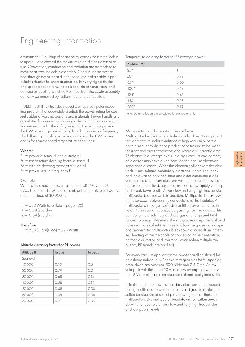
171
Engi
neer
ing
info
rmat
ion
HUBER+SUHNER Microwave assembliesAbbreviations see page 176
environment. A buildup of heat energy causes the internal cable temperature to exceed the maximum rated dielectric tempera-ture. Convection, conduction and radiation are methods to re-move heat from the cable assembly. Conduction transfer of heat through the outer and inner conductors of a cable is parti-cularly effective for short assemblies. For very high altitudes and space applications, the air is too thin or nonexistent and convection cooling is ineffective. Heat from the cable assembly can only be removed by radiant heat and conduction.
HUBER+SUHNER has developed a unique computer-mode-ling program that accurately predicts the power rating for coa-xial cables of varying designs and materials. Power handling is calculated for convection cooling only. Conduction and radia-tion are included in the safety margins. These charts provide the CW or average power rating for all cables versus frequency. The following calculation shows how to use the CW power charts for non-standard temperature conditions:
Where:P = power at temp, t1 and altitude a1Ft = temperature derating factor at temp. t1Fa = altitude derating factor at altitude a1Pf = power level at frequency f1
Example:What is the average power rating for HUBER+SUHNER 32051 cable at 12 GHz at an ambient temperature of 100 °C and an altitude of 30 000 ft?
Pf = 580 Watts (see data – page 122)Ft = 0.58 (see chart)Fa = 0.68 (see chart) Therefore: P = 580 (0.58)(0.68) = 229 Watts
Altitude derating factor for RF power
Altitude ft fa avg fa peak
Sea level 1 1
10 000 0.90 0.5
20 000 0.79 0.2
30 000 0.68 0.14
40 000 0.58 0.10
50 000 0.48 0.08
60 000 0.38 0.06
70 000 0.29 0.05
Engineering information
Temperature derating factor for RF average power
Ambient °C ft
25° 1
50° 0.83
85° 0.66
100° 0.58
125° 0.43
150° 0.28
200° 0.15
Note: Derating factors are calculated for convection only.
Multipaction and ionisation breakdownMultipactor breakdown is a failure mode of an RF component that only occurs under conditions of high vacuum, where a certain frequency distance product condition exists between the inner and outer conductors and where a sufficiently large RF electric field strength exists. In a high vacuum environment, an electron may have a free path longer than the electrode separation distance. When this electron collides with the elec-trode it may release secondary electrons. If both frequency and the distance between inner and outer conductor are fa-vorable, the secondary electrons will be accelerated by the electromagnetic field. Large electron densities rapidly build up and breakdown results. At very low and very high frequencies multipactor breakdown is impossible. Multipactor breakdown can also occur between the conductor and the insulator. A multipactor discharge itself adsorbs little power, but once ini-tiated it can cause increased outgassing from materials within components, which may lead to a gas discharge and total failure. To prevent this event, the microwave components should have vent holes of sufficient size to allow the gasses to escape at a known rate. Multipactor breakdown also results in increa-sed heating within the cable or connector, noise generation, harmonic distortion and intermodulation (when multiple fre-quency RF signals are applied).
For every vacuum application the power handling should be calculated individually. The worst frequencies for multipactor breakdown are between 500 MHz and 2.5 GHz. At low voltage levels (less than 20 V) and low average power (less than 8 W), multipactor breakdown is theoretically impossible.
In ionisation breakdown, secondary electrons are produced through collisions between electrons and gas molecules. Ioni-sation breakdown occurs at pressures higher than those for multipaction. Like multipactor breakdown, ionisation break-down is not possible at very low and very high frequenciesand low power levels.
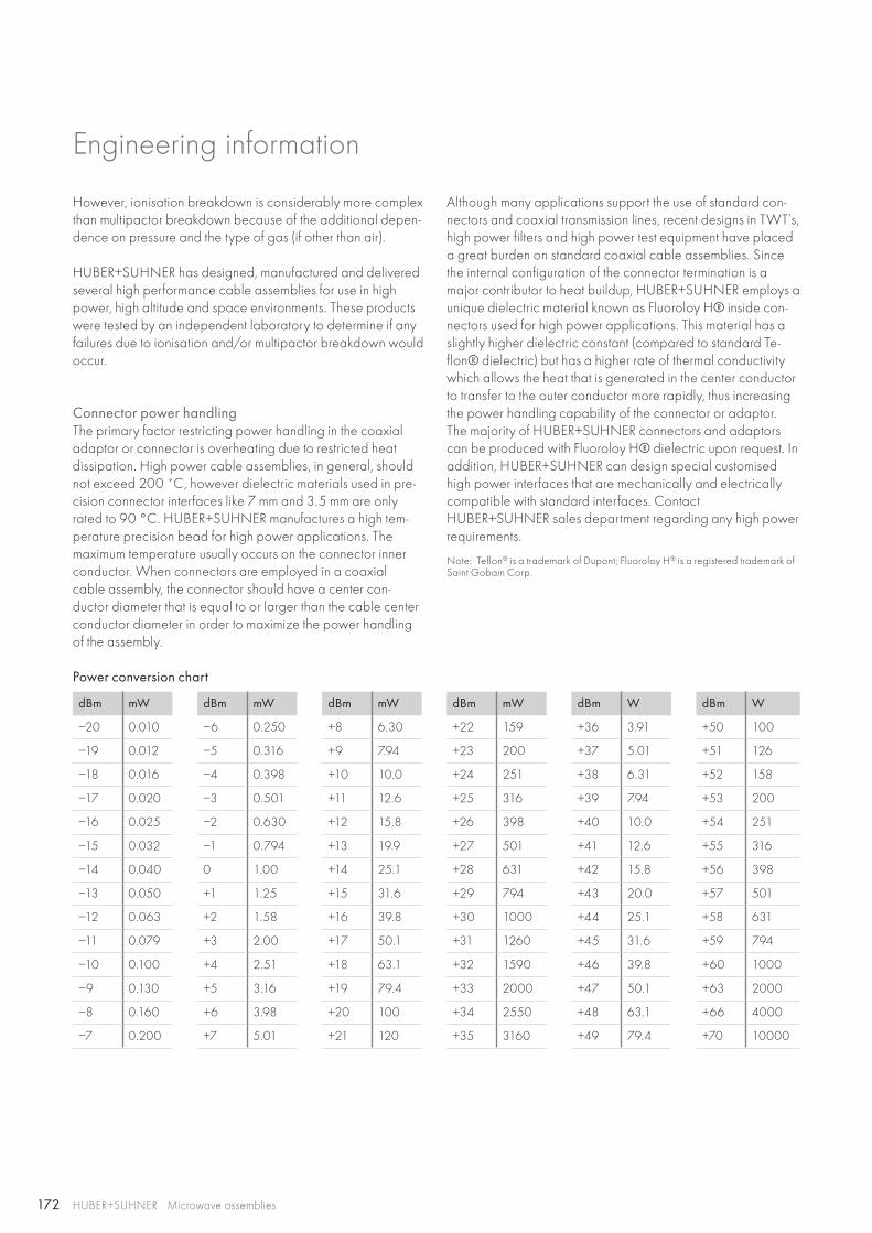
172 HUBER+SUHNER Microwave assemblies
Engineering information
However, ionisation breakdown is considerably more complex than multipactor breakdown because of the additional depen-dence on pressure and the type of gas (if other than air).
HUBER+SUHNER has designed, manufactured and delivered several high performance cable assemblies for use in high power, high altitude and space environments. These products were tested by an independent laboratory to determine if any failures due to ionisation and/or multipactor breakdown would occur.
Connector power handlingThe primary factor restricting power handling in the coaxial adaptor or connector is overheating due to restricted heat dissipation. High power cable assemblies, in general, should not exceed 200 ̊ C, however dielectric materials used in pre-cision connector interfaces like 7 mm and 3.5 mm are only rated to 90 °C. HUBER+SUHNER manufactures a high tem-perature precision bead for high power applications. The maximum temperature usually occurs on the connector inner conductor. When connectors are employed in a coaxialcable assembly, the connector should have a center con-ductor diameter that is equal to or larger than the cable center conductor diameter in order to maximize the power handling of the assembly.
Although many applications support the use of standard con-nectors and coaxial transmission lines, recent designs in TWT’s, high power filters and high power test equipment have placed a great burden on standard coaxial cable assemblies. Since the internal configuration of the connector termination is a major contributor to heat buildup, HUBER+SUHNER employs a unique dielectric material known as Fluoroloy H® inside con-nectors used for high power applications. This material has a slightly higher dielectric constant (compared to standard Te-flon® dielectric) but has a higher rate of thermal conductivity which allows the heat that is generated in the center conductor to transfer to the outer conductor more rapidly, thus increasing the power handling capability of the connector or adaptor. The majority of HUBER+SUHNER connectors and adaptors can be produced with Fluoroloy H® dielectric upon request. In addition, HUBER+SUHNER can design special customised high power interfaces that are mechanically and electrically compatible with standard interfaces. Contact HUBER+SUHNER sales department regarding any high power requirements.
Note: Teflon® is a trademark of Dupont; Fluoroloy H® is a registered trademark of Saint Gobain Corp.
Power conversion chart
dBm mW dBm mW dBm mW dBm mW dBm W dBm W
−20 0.010 −6 0.250 +8 6.30 +22 159 +36 3.91 +50 100
−19 0.012 −5 0.316 +9 7.94 +23 200 +37 5.01 +51 126
−18 0.016 −4 0.398 +10 10.0 +24 251 +38 6.31 +52 158
−17 0.020 −3 0.501 +11 12.6 +25 316 +39 7.94 +53 200
−16 0.025 −2 0.630 +12 15.8 +26 398 +40 10.0 +54 251
−15 0.032 −1 0.794 +13 19.9 +27 501 +41 12.6 +55 316
−14 0.040 0 1.00 +14 25.1 +28 631 +42 15.8 +56 398
−13 0.050 +1 1.25 +15 31.6 +29 794 +43 20.0 +57 501
−12 0.063 +2 1.58 +16 39.8 +30 1000 +44 25.1 +58 631
−11 0.079 +3 2.00 +17 50.1 +31 1260 +45 31.6 +59 794
−10 0.100 +4 2.51 +18 63.1 +32 1590 +46 39.8 +60 1000
−9 0.130 +5 3.16 +19 79.4 +33 2000 +47 50.1 +63 2000
−8 0.160 +6 3.98 +20 100 +34 2550 +48 63.1 +66 4000
−7 0.200 +7 5.01 +21 120 +35 3160 +49 79.4 +70 10000
173
Engi
neer
ing
info
rmat
ion
HUBER+SUHNER Microwave assembliesAbbreviations see page 176
Engineering information
Intermodulation distortion in passive componentsIntermodulation distortion in passive microwave components is caused by internal nonlinearities. In a truly linear system, the output is directly proportional to the input. In a nonlinear system, the output signal is distorted by changes in the amplitude of the input signal. Intermodulation distortion creates new output signals from the nonlinear combinations of two or more input signals mixed together. A nonlinear circuit will create an infinite number of harmonics from two fundamen-tal frequencies (f1 and f2). A particular concern for telecommu-nication systems engineers is the intermodulation product of the third order (such as 2f1 – f2 and 2f2 – f1), especially if f1 and f2 are closely spaced. With certain system designs and band-width allocations, the third order intermodulation products can be generated at the same frequencies as the receive channels of the system. In general, intermodulation products increase system noise and reduce the number of available channels.
Intermodulation distortion is most pronounced in systems where the high power transmission and low power receiver signals are carried simultaneously in the same transmission line, such as in the cable between the duplexer and the antenna in GSM base stations and in certain space applications. For low power levels, the effects of intermodulation distortion are significantly less. HUBER+SUHNER is involved in the research of the inter-modulation problem as a participant in the IEC TC46 WG6 passive intermodulation working group.
Coaxial cable assemblies have often been viewed as linear components. However, pure linear components do not exist. There are small nonlinearities in the connectors and in the ca-ble to connector junctions. Intermodulation distortion in con-nectors is usually caused by thin surface oxide layers at the connector junctions or by insufficient contact pressure whenthe current-carrying contact zones become separated. Sepa-ration is usually microscopic and can be caused by either elec-tron tunneling or microscopic arcing. The presence of ferroma-gnetic materials in the current path may also contribute to intermodulation distortion.
Some simple design rules can help avoid intermodulation dis-tortions in coaxial cable assemblies:
• Use of semi-rigid cable with a seamless outer conductor in place of flexible cable.
• Use of a solid center conductor in place of a strandedcenter conductor.
• Directly attach the outer conductor to the connector bodyby soldering or clamping in lieu of crimping.
• Limit the number of parts in the current path.• Eliminate contaminants in the current path.• Use high quality machining in the connector parts with a
smooth surface finish.• Avoid contaminants in the plating solutions.
• Ensure adequate and uniform plating thickness.• Avoid use of magnetic materials in the current-carrying path.• Ensure adequate contact pressure.• Contact surface of female contact fingers should cover as
close to 360 as possible (i. e. narrow slots or slotless).• Use connector interfaces with radial dimensions as large as
possible (7/16 over N, N over SMA).
Space applicationsEvery space application is unique and requires careful consi-deration before selecting the components to be used. A space environment subjects components and assemblies to severe environmental stress:
• Low earth orbit spacecraft subject solder joints, welds, brazements and mechanical connections to continuous hot/cold thermal cycling every 90 minutes. The manufacturing process must be carefully controlled per NASA STD-8739 requirements to assure consistent, reliable connections and assemblies. Solder connections must be 100 % X-rayed to assure their integrity and reliability.
• There is no atmosphere so convection cooling does not occur. Excess heat must be removed by radiation, which requires the surface of the connectors to be an infrared emitter, or by conduction which requires a secondaryheat sink.
• Certain materials "outgas" in the extreme vacuum of space which requires the designer to select materials and compon-ents that meet NASA requirements for Total Mass Loss (TML) and Collected Volatile Condensable Material (CVCM) to avoid contamination of optics and other sensitive equipment on board the spacecraft.
• Materials must be carefully chosen so that ionising radiation does not destroy the connector or cable dielectric or the cable jacket.
• Multipaction failure (described in more detail herein) is a con-cern for high power applications.
• Intermodulation distortion (described in more detail herein) is a concern within systems where high power transmitting and low power receiving signals need to be carried simultane-ously in the same transmission line.
• The manufacturing environment must be carefully controlled and the packaging materials selected to prevent dust and particles from accumulating on the components and subse-quently contaminating the spacecraft.
Processes and controls used by HUBER+SUHNER for procure-ment, manufacture, assembly, soldering, X-ray, inspection and testing have been certified by NASA for use in spacecraft applications. HUBER+SUHNER has the design, manufacturing, testing and applications experience and expertise to supply your needs for passive microwave devices for use in any space environment.
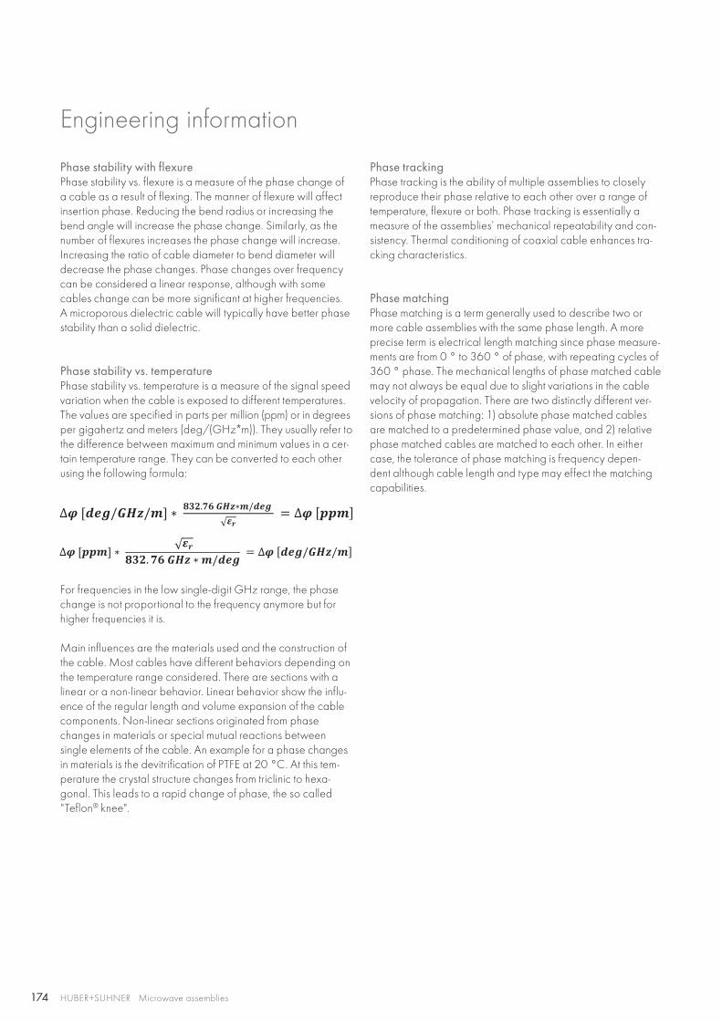
174 HUBER+SUHNER Microwave assemblies
Engineering information
Phase stability with flexurePhase stability vs. flexure is a measure of the phase change of a cable as a result of flexing. The manner of flexure will affect insertion phase. Reducing the bend radius or increasing the bend angle will increase the phase change. Similarly, as the number of flexures increases the phase change will increase. Increasing the ratio of cable diameter to bend diameter will decrease the phase changes. Phase changes over frequency can be considered a linear response, although with some cables change can be more significant at higher frequencies.A microporous dielectric cable will typically have better phase stability than a solid dielectric.
Phase stability vs. temperaturePhase stability vs. temperature is a measure of the signal speed variation when the cable is exposed to different temperatures. The values are specified in parts per million (ppm) or in degrees per gigahertz and meters (deg/(GHz*m)). They usually refer to the difference between maximum and minimum values in a cer-tain temperature range. They can be converted to each other using the following formula:
For frequencies in the low single-digit GHz range, the phase change is not proportional to the frequency anymore but for higher frequencies it is.
Main influences are the materials used and the construction of the cable. Most cables have different behaviors depending on the temperature range considered. There are sections with a linear or a non-linear behavior. Linear behavior show the influ-ence of the regular length and volume expansion of the cable components. Non-linear sections originated from phasechanges in materials or special mutual reactions between single elements of the cable. An example for a phase changes in materials is the devitrification of PTFE at 20 °C. At this tem-perature the crystal structure changes from triclinic to hexa-gonal. This leads to a rapid change of phase, the so called "Teflon® knee".
Phase matchingPhase matching is a term generally used to describe two or more cable assemblies with the same phase length. A more precise term is electrical length matching since phase measure-ments are from 0 ° to 360 ° of phase, with repeating cycles of 360 ° phase. The mechanical lengths of phase matched cable may not always be equal due to slight variations in the cable velocity of propagation. There are two distinctly different ver-sions of phase matching: 1) absolute phase matched cables are matched to a predetermined phase value, and 2) relative phase matched cables are matched to each other. In either case, the tolerance of phase matching is frequency depen-dent although cable length and type may effect the matching capabilities.
Phase trackingPhase tracking is the ability of multiple assemblies to closely reproduce their phase relative to each other over a range of temperature, flexure or both. Phase tracking is essentially a measure of the assemblies’ mechanical repeatability and con-sistency. Thermal conditioning of coaxial cable enhances tra-cking characteristics.

175
0.435 ×0.435
Engi
neer
ing
info
rmat
ion
HUBER+SUHNER Microwave assembliesAbbreviations see page 176
Engineering information
Phase matching of cable assemblies
DefinitionThe term "phase matching" refers to the relative electrical length of an assembly compared with a reference cable ora given electrical length.
Absolute length
Relative length
Guarantee of phase matchingHUBER+SUHNER guarantees phase matching ex-factory. The relevant measurement logs are included in the supply. It is es-sential during installation and service to ensure that all assem-blies of a phase matched set are exposed to the identical ther-mal and mechanical stresses.
Reference cablesUsually, a reference cable is produced for each phase mat-ched assembly set when an initial production run takes place. The absolute electrical length measured is internally saved. The reference cables are stored during 10 to 20 years under con-trolled conditions (temperature, humidity) together with the order data to allow individual assemblies to be replaced whenever the need arises.
Attenuation (insertion loss)Attenuation is a measure of the ability of a component to carry an RF signal efficiently. Coaxial cable loss is the sum of the die-lectric and conductor losses and is a function of the materials used to manufacture the cable. Attenuation stability with flexure will have similar response characteristics as "phase vs. flexure" described previously, as will the "tracking" characteristics. Attenuation matching will not be as dependent upon the diel-ectric style, although for long lengths the insertion loss stability vs. flexure is critical.
Inner conductor loss (where F is the frequency in MHz)
Outer conductor loss
Dielectric loss Where: = power factor (loss tangent)= 0.00016 (
r = 2.1)
= 0.00005 (r = 1.6)

176 HUBER+SUHNER Microwave assemblies
Engineering information
Abbreviations
Al aluminiumAlCuAg siver plated copper clad aluminiumCuAg silver plated copperCuSn tin plated copperECTFE ethylen-chlortrifluorethylenETFE ethylene-tetrafluoroethyleneFEP fluorinated ethylene propyleneLD-PTFE low density PTFELSFH low smoke free of halogenMIL hexagonal nut with safety holesML mounting holePE polyethylenePTFE polytetrafluorethenPUR polyurethaneQL quick lockSn soaked Cu braid tin soaked copper braidSPE foamed polyethyleneStCu copper clad steelStCuAg silver plater copper clad steelTP tin plated TP_M17 tin plated, MIL-C-17_QPLULD-PTFE ultra low density PTFE

177
Engi
neer
ing
info
rmat
ion
HUBER+SUHNER Microwave assembliesAbbreviations see page 176
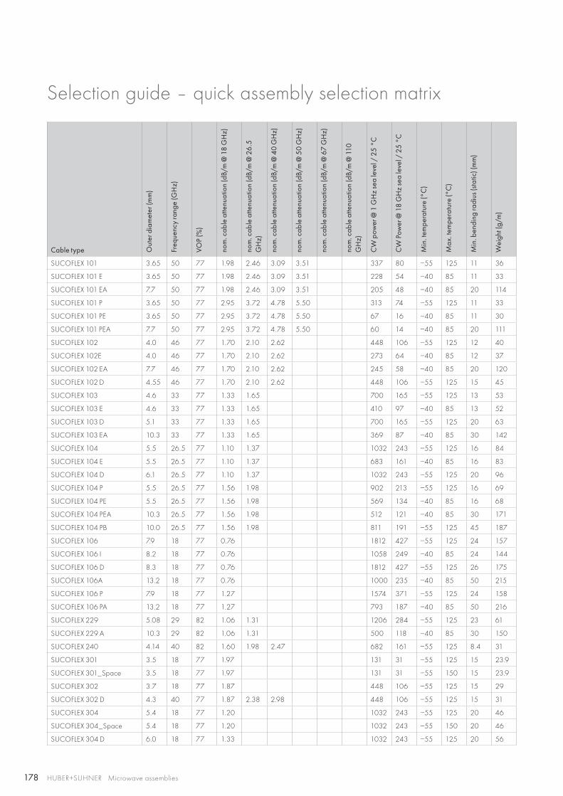
178 HUBER+SUHNER Microwave assemblies
Selection guide – quick assembly selection matrix
Cable type Out
er d
iam
eter
(mm
)
Freq
uenc
y ra
nge
(GH
z)
VOP
(%)
nom
. cab
le a
ttenu
atio
n (d
B/m
@ 1
8 G
Hz)
nom
. cab
le a
ttenu
atio
n (d
B/m
@ 2
6.5
G
Hz)
nom
. cab
le a
ttenu
atio
n (d
B/m
@ 4
0 G
Hz)
nom
. cab
le a
ttenu
atio
n (d
B/m
@ 5
0 G
Hz)
nom
. cab
le a
ttenu
atio
n (d
B/m
@ 6
7 G
Hz)
nom
. cab
le a
ttenu
atio
n (d
B/m
@ 1
10
GH
z)
CW
pow
er @
1 G
Hz
sea
leve
l / 2
5 °C
CW
Pow
er @
18
GH
z se
a le
vel /
25
°C
Min
. tem
pera
ture
(°C
)
Max
. tem
pera
ture
(°C
)
Min
. ben
ding
radi
us (s
tatic
) (m
m)
Wei
ght (
g/m
)
SUCOFLEX 101 3.65 50 77 1.98 2.46 3.09 3.51 337 80 −55 125 11 36
SUCOFLEX 101 E 3.65 50 77 1.98 2.46 3.09 3.51 228 54 −40 85 11 33
SUCOFLEX 101 EA 7.7 50 77 1.98 2.46 3.09 3.51 205 48 −40 85 20 114
SUCOFLEX 101 P 3.65 50 77 2.95 3.72 4.78 5.50 313 74 −55 125 11 33
SUCOFLEX 101 PE 3.65 50 77 2.95 3.72 4.78 5.50 67 16 −40 85 11 30
SUCOFLEX 101 PEA 7.7 50 77 2.95 3.72 4.78 5.50 60 14 −40 85 20 111
SUCOFLEX 102 4.0 46 77 1.70 2.10 2.62 448 106 −55 125 12 40
SUCOFLEX 102E 4.0 46 77 1.70 2.10 2.62 273 64 −40 85 12 37
SUCOFLEX 102 EA 7.7 46 77 1.70 2.10 2.62 245 58 −40 85 20 120
SUCOFLEX 102 D 4.55 46 77 1.70 2.10 2.62 448 106 −55 125 15 45
SUCOFLEX 103 4.6 33 77 1.33 1.65 700 165 −55 125 13 53
SUCOFLEX 103 E 4.6 33 77 1.33 1.65 410 97 −40 85 13 52
SUCOFLEX 103 D 5.1 33 77 1.33 1.65 700 165 −55 125 20 63
SUCOFLEX 103 EA 10.3 33 77 1.33 1.65 369 87 −40 85 30 142
SUCOFLEX 104 5.5 26.5 77 1.10 1.37 1032 243 −55 125 16 84
SUCOFLEX 104 E 5.5 26.5 77 1.10 1.37 683 161 −40 85 16 83
SUCOFLEX 104 D 6.1 26.5 77 1.10 1.37 1032 243 −55 125 20 96
SUCOFLEX 104 P 5.5 26.5 77 1.56 1.98 902 213 −55 125 16 69
SUCOFLEX 104 PE 5.5 26.5 77 1.56 1.98 569 134 −40 85 16 68
SUCOFLEX 104 PEA 10.3 26.5 77 1.56 1.98 512 121 −40 85 30 171
SUCOFLEX 104 PB 10.0 26.5 77 1.56 1.98 811 191 −55 125 45 187
SUCOFLEX 106 7.9 18 77 0.76 1812 427 −55 125 24 157
SUCOFLEX 106 I 8.2 18 77 0.76 1058 249 −40 85 24 144
SUCOFLEX 106 D 8.3 18 77 0.76 1812 427 −55 125 26 175
SUCOFLEX 106A 13.2 18 77 0.76 1000 235 −40 85 50 215
SUCOFLEX 106 P 7.9 18 77 1.27 1574 371 −55 125 24 158
SUCOFLEX 106 PA 13.2 18 77 1.27 793 187 −40 85 50 216
SUCOFLEX 229 5.08 29 82 1.06 1.31 1206 284 −55 125 23 61
SUCOFLEX 229 A 10.3 29 82 1.06 1.31 500 118 −40 85 30 150
SUCOFLEX 240 4.14 40 82 1.60 1.98 2.47 682 161 −55 125 8.4 31
SUCOFLEX 301 3.5 18 77 1.97 131 31 −55 125 15 23.9
SUCOFLEX 301_Space 3.5 18 77 1.97 131 31 −55 150 15 23.9
SUCOFLEX 302 3.7 18 77 1.87 448 106 −55 125 15 29
SUCOFLEX 302 D 4.3 40 77 1.87 2.38 2.98 448 106 −55 125 15 31
SUCOFLEX 304 5.4 18 77 1.20 1032 243 −55 125 20 46
SUCOFLEX 304_Space 5.4 18 77 1.20 1032 243 −55 150 20 46
SUCOFLEX 304 D 6.0 18 77 1.33 1032 243 −55 125 20 56
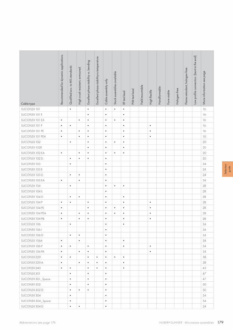
179HUBER+SUHNER Microwave assembliesAbbreviations see page 176
Sele
ctio
n gu
ide
Cable type Reco
mm
ende
d fo
r dyn
amic
app
licat
ions
Qua
lifie
d ac
c. to
MIL
stan
dard
s
Hig
h cr
ush
resi
stan
t, ar
mou
red
Exce
llent
pha
se st
abili
ty v
s. b
endi
ng
Exce
llent
pha
se st
abili
tyvs
.tem
pera
ture
Cab
le a
ssem
bly
only
Stoc
k as
sem
blie
s ava
ilabl
e
RF te
st le
ad
PIM
test
lead
Fiel
d m
ount
able
Hig
h fle
xlife
Han
dfor
mab
le
Form
-sta
ble
Hal
ogen
-free
Flam
e re
tard
ant,
halo
gen-
free
Low
pro
file
conn
ecto
rs (
bent
to th
e en
d)
Mor
e in
form
atio
n se
e pa
ge
SUCOFLEX 101 • • • • • 16
SUCOFLEX 101 E • • • 16
SUCOFLEX 101 EA • • • • • • 16
SUCOFLEX 101 P • • • • • • 16
SUCOFLEX 101 PE • • • • • • 16
SUCOFLEX 101 PEA • • • • • • 16
SUCOFLEX 102 • • • • • 20
SUCOFLEX 102E • • • 20
SUCOFLEX 102 EA • • • • • • 20
SUCOFLEX 102 D • • • • 20
SUCOFLEX 103 • • 24
SUCOFLEX 103 E • 24
SUCOFLEX 103 D • • • 24
SUCOFLEX 103 EA • • • 24
SUCOFLEX 104 • • • • 28
SUCOFLEX 104 E • 28
SUCOFLEX 104 D • • • • 28
SUCOFLEX 104 P • • • • • • 28
SUCOFLEX 104 PE • • • • • • 28
SUCOFLEX 104 PEA • • • • • • • 28
SUCOFLEX 104 PB • • • • • • 28
SUCOFLEX 106 • • • 34
SUCOFLEX 106 I • 34
SUCOFLEX 106 D • • • 34
SUCOFLEX 106A • • • • 34
SUCOFLEX 106 P • • • • • • 34
SUCOFLEX 106 PA • • • • • 34
SUCOFLEX 229 • • • • • • • 38
SUCOFLEX 229 A • • • • • • 38
SUCOFLEX 240 • • • • • • 43
SUCOFLEX 301 • • • 47
SUCOFLEX 301_Space • • • 47
SUCOFLEX 302 • • • 50
SUCOFLEX 302 D • • • • 50
SUCOFLEX 304 • • 54
SUCOFLEX 304_Space • • 54
SUCOFLEX 304 D • • • 54
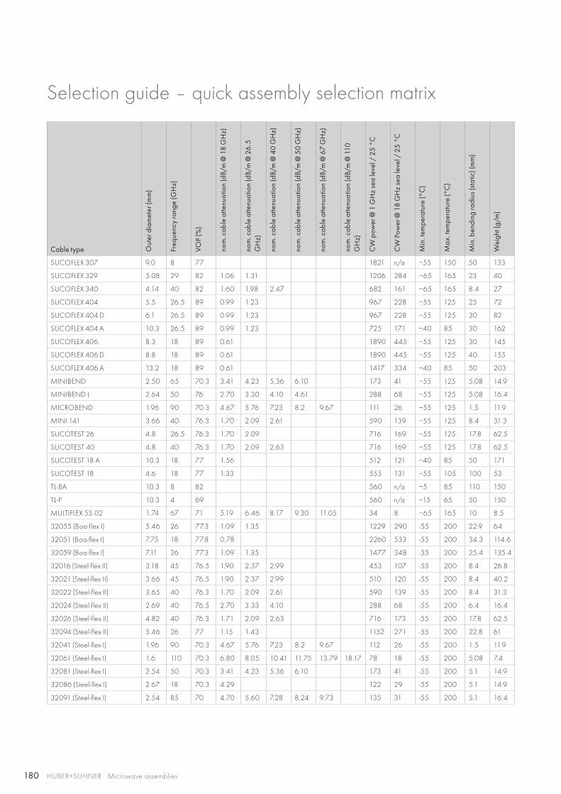
180 HUBER+SUHNER Microwave assemblies
Selection guide – quick assembly selection matrix
Cable type Out
er d
iam
eter
(mm
)
Freq
uenc
y ra
nge
(GH
z)
VOP
(%)
nom
. cab
le a
ttenu
atio
n (d
B/m
@ 1
8 G
Hz)
nom
. cab
le a
ttenu
atio
n (d
B/m
@ 2
6.5
G
Hz)
nom
. cab
le a
ttenu
atio
n (d
B/m
@ 4
0 G
Hz)
nom
. cab
le a
ttenu
atio
n (d
B/m
@ 5
0 G
Hz)
nom
. cab
le a
ttenu
atio
n (d
B/m
@ 6
7 G
Hz)
nom
. cab
le a
ttenu
atio
n (d
B/m
@ 1
10
GH
z)
CW
pow
er @
1 G
Hz
sea
leve
l / 2
5 °C
CW
Pow
er @
18
GH
z se
a le
vel /
25
°C
Min
. tem
pera
ture
(°C
)
Max
. tem
pera
ture
(°C
)
Min
. ben
ding
radi
us (s
tatic
) (m
m)
Wei
ght (
g/m
)
SUCOFLEX 307 9.0 8 77 1821 n/a −55 150 50 133
SUCOFLEX 329 5.08 29 82 1.06 1.31 1206 284 −65 165 23 40
SUCOFLEX 340 4.14 40 82 1.60 1.98 2.47 682 161 −65 165 8.4 27
SUCOFLEX 404 5.5 26.5 89 0.99 1.23 967 228 −55 125 25 72
SUCOFLEX 404 D 6.1 26.5 89 0.99 1.23 967 228 −55 125 30 82
SUCOFLEX 404 A 10.3 26.5 89 0.99 1.23 725 171 −40 85 30 162
SUCOFLEX 406 8.3 18 89 0.61 1890 445 −55 125 30 145
SUCOFLEX 406 D 8.8 18 89 0.61 1890 445 −55 125 40 155
SUCOFLEX 406 A 13.2 18 89 0.61 1417 334 −40 85 50 203
MINIBEND 2.50 65 70.3 3.41 4.23 5.36 6.10 173 41 −55 125 5.08 14.9
MINIBEND L 2.64 50 76 2.70 3.30 4.10 4.61 288 68 −55 125 5.08 16.4
MICROBEND 1.96 90 70.3 4.67 5.76 7.23 8.2 9.67 111 26 −55 125 1.5 11.9
MINI 141 3.66 40 76.3 1.70 2.09 2.61 590 139 −55 125 8.4 31.3
SUCOTEST 26 4.8 26.5 76.3 1.70 2.09 716 169 −55 125 17.8 62.5
SUCOTEST 40 4.8 40 76.3 1.70 2.09 2.63 716 169 −55 125 17.8 62.5
SUCOTEST 18 A 10.3 18 77 1.56 512 121 −40 85 50 171
SUCOTEST 18 4.6 18 77 1.33 555 131 −55 105 100 53
TL-8A 10.3 8 82 560 n/a −5 85 110 150
TL-P 10.3 4 69 560 n/a −15 65 50 150
MULTIFLEX 53-02 1.74 67 71 5.19 6.46 8.17 9.30 11.05 34 8 −65 165 10 8.5
32055 (Boa-flex I) 5.46 26 77.3 1.09 1.35 1229 290 -55 200 22.9 64
32051 (Boa-flex I) 7.75 18 77.8 0.78 2260 533 -55 200 34.3 114.6
32059 (Boa-flex I) 7.11 26 77.3 1.09 1.35 1477 348 -55 200 25.4 135.4
32016 (Steel-flex II) 3.18 45 76.5 1.90 2.37 2.99 453 107 -55 200 8.4 26.8
32021 (Steel-flex II) 3.66 45 76.5 1.90 2.37 2.99 510 120 -55 200 8.4 40.2
32022 (Steel-flex II) 3.65 40 76.3 1.70 2.09 2.61 590 139 -55 200 8.4 31.3
32024 (Steel-flex II) 2.69 40 76.5 2.70 3.33 4.10 288 68 -55 200 6.4 16.4
32026 (Steel-flex II) 4.82 40 76.3 1.71 2.09 2.63 716 173 -55 200 17.8 62.5
32094 (Steel-flex II) 5.46 26 77 1.15 1.43 1152 271 -55 200 22.8 61
32041 (Steel-flex I) 1.96 90 70.3 4.67 5.76 7.23 8.2 9.67 112 26 -55 200 1.5 11.9
32061 (Steel-flex I) 1.6 110 70.3 6.80 8.05 10.41 11.75 13.79 18.17 78 18 -55 200 5.08 7.4
32081 (Steel-flex I) 2.54 50 70.3 3.41 4.23 5.36 6.10 173 41 -55 200 5.1 14.9
32086 (Steel-flex I) 2.67 18 70.3 4.29 122 29 -55 200 5.1 14.9
32091 (Steel-flex I) 2.54 85 70 4.70 5.60 7.28 8.24 9.73 135 31 -55 200 5.1 16.4

181HUBER+SUHNER Microwave assembliesAbbreviations see page 176
Sele
ctio
n gu
ide
Cable type Reco
mm
ende
d fo
r dyn
amic
app
licat
ions
Qua
lifie
d ac
c. to
MIL
stan
dard
s
Hig
h cr
ush
resi
stan
t, ar
mou
red
Exce
llent
pha
se st
abili
ty v
s. b
endi
ng
Exce
llent
pha
se st
abili
tyvs
.tem
pera
ture
Cab
le a
ssem
bly
only
Stoc
k as
sem
blie
s ava
ilabl
e
RF te
st le
ad
PIM
test
lead
Fiel
d m
ount
able
Hig
h fle
xlife
Han
dfor
mab
le
Form
-sta
ble
Hal
ogen
-free
Flam
e re
tard
ant,
halo
gen-
free
Low
pro
file
conn
ecto
rs (
bent
to th
e en
d)
Mor
e in
form
atio
n se
e pa
ge
SUCOFLEX 307 • • 57
SUCOFLEX 329 • • • • 60
SUCOFLEX 340 • • • • 63
SUCOFLEX 404 • • • 67
SUCOFLEX 404 D • • • • 67
SUCOFLEX 404 A • • • 67
SUCOFLEX 406 • • • 70
SUCOFLEX 406 D • • • • 70
SUCOFLEX 406 A • • • 70
MINIBEND • • • • 76
MINIBEND L • • • • 86
MICROBEND • • • • 88
MINI 141 • • • • 97
SUCOTEST 26 • • • 104
SUCOTEST 40 • • • 104
SUCOTEST 18 A • • • • • • 107
SUCOTEST 18 • • • 110
TL-8A • • • • • 112
TL-P • • • • • • 114
MULTIFLEX 53-02 • • • 141
32055 (Boa-flex I) 120
32051 (Boa-flex I) 120
32059 (Boa-flex I) • 120
32016 (Steel-flex II) • • • 124
32021 (Steel-flex II) • • • • 125
32022 (Steel-flex II) • • • 124
32024 (Steel-flex II) • 124
32026 (Steel-flex II) • • 125
32094 (Steel-flex II) • • • • 125
32041 (Steel-flex I) • • 128
32061 (Steel-flex I) 128
32081 (Steel-flex I) • • 128
32086 (Steel-flex I) • • 128
32091 (Steel-flex I) • • 128
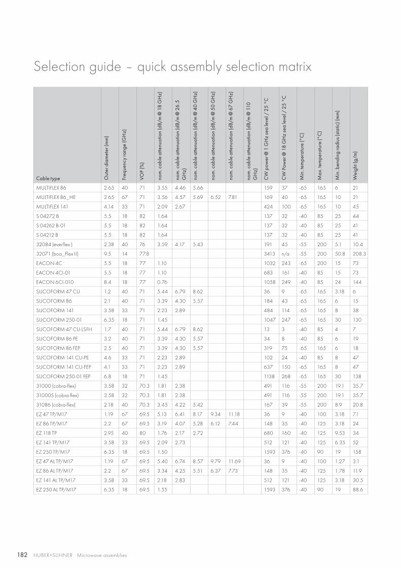
182 HUBER+SUHNER Microwave assemblies
Selection guide – quick assembly selection matrix
Cable type Out
er d
iam
eter
(mm
)
Freq
uenc
y ra
nge
(GH
z)
VOP
(%)
nom
. cab
le a
ttenu
atio
n (d
B/m
@ 1
8 G
Hz)
nom
. cab
le a
ttenu
atio
n (d
B/m
@ 2
6.5
G
Hz)
nom
. cab
le a
ttenu
atio
n (d
B/m
@ 4
0 G
Hz)
nom
. cab
le a
ttenu
atio
n (d
B/m
@ 5
0 G
Hz)
nom
. cab
le a
ttenu
atio
n (d
B/m
@ 6
7 G
Hz)
nom
. cab
le a
ttenu
atio
n (d
B/m
@ 1
10
GH
z)
CW
pow
er @
1 G
Hz
sea
leve
l / 2
5 °C
CW
Pow
er @
18
GH
z se
a le
vel /
25
°C
Min
. tem
pera
ture
(°C
)
Max
. tem
pera
ture
(°C
)
Min
. ben
ding
radi
us (s
tatic
) (m
m)
Wei
ght (
g/m
)
MULTIFLEX 86 2.65 40 71 3.55 4.46 5.66 159 37 -65 165 6 21
MULTIFLEX 86_HE 2.65 67 71 3.56 4.57 5.69 6.52 7.81 169 40 -65 165 10 21
MULTIFLEX 141 4.14 33 71 2.09 2.67 424 100 -65 165 10 45
S 04272 B 5.5 18 82 1.64 137 32 -40 85 25 44
S 04262 B-01 5.5 18 82 1.64 137 32 -40 85 25 41
S 04212 B 5.5 18 82 1.64 137 32 -40 85 25 41
32084 (everflex ) 2.38 40 76 3.59 4.17 5.43 191 45 -55 200 5.1 10.4
32071 (boa_Flex II) 9.5 14 77.8 3413 n/a -55 200 50.8 208.3
EACON 4C 5.5 18 77 1.10 1032 243 -65 200 15 73
EACON 4CI-01 5.5 18 77 1.10 683 161 -40 85 15 73
EACON 6CI-010 8.4 18 77 0.76 1058 249 -40 85 24 144
SUCOFORM 47 CU 1.2 40 71 5.44 6.79 8.62 36 9 -65 165 3.18 6
SUCOFORM 86 2.1 40 71 3.39 4.30 5.57 184 43 -65 165 6 15
SUCOFORM 141 3.58 33 71 2.23 2.89 484 114 -65 165 8 38
SUCOFORM 250-01 6.35 18 71 1.45 1047 247 -65 165 30 130
SUCOFORM 47 CU-LSFH 1.7 40 71 5.44 6.79 8.62 13 3 -40 85 4 7
SUCOFORM 86 PE 3.2 40 71 3.39 4.30 5.57 34 8 -40 85 6 19
SUCOFORM 86 FEP 2.5 40 71 3.39 4.30 5.57 319 75 -65 165 6 18
SUCOFORM 141 CU-PE 4.6 33 71 2.23 2.89 102 24 -40 85 8 47
SUCOFORM 141 CU-FEP 4.1 33 71 2.23 2.89 637 150 -65 165 8 47
SUCOFORM 250-01 FEP 6.8 18 71 1.45 1138 268 -65 165 30 138
31000 (cobra-flex) 3.58 32 70.3 1.81 2.38 491 116 -55 200 19.1 35.7
31000S (cobra-flex) 3.58 32 70.3 1.81 2.38 491 116 -55 200 19.1 35.7
31086 (cobra-flex) 2.18 40 70.3 3.45 4.22 5.42 167 39 -55 200 8.9 20.8
EZ 47 TP/M17 1.19 67 69.5 5.13 6.41 8.17 9.34 11.18 36 9 -40 100 3.18 7.1
EZ 86 TP/M17 2.2 67 69.5 3.19 4.07 5.28 6.12 7.44 148 35 -40 125 3.18 24
EZ 118 TP 2.95 40 80 1.76 2.17 2.72 680 160 -40 125 9.53 34
EZ 141 TP/M17 3.58 33 69.5 2.09 2.73 512 121 -40 125 6.35 52
EZ 250 TP/M17 6.35 18 69.5 1.50 1593 376 -40 90 19 158
EZ 47 AL TP/M17 1.19 67 69.5 5.40 6.74 8.57 9.79 11.69 36 9 -40 100 1.27 3.1
EZ 86 AL TP/M17 2.2 67 69.5 3.34 4.25 5.51 6.37 7.73 148 35 -40 125 1.78 11.9
EZ 141 AL TP/M17 3.58 33 69.5 2.18 2.83 512 121 -40 125 3.18 30.5
EZ 250 AL TP/M17 6.35 18 69.5 1.55 1593 376 -40 90 19 88.6
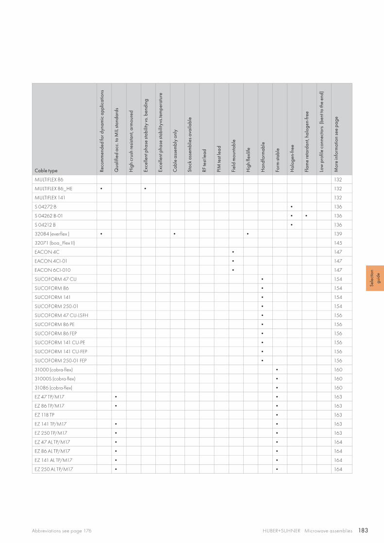
183HUBER+SUHNER Microwave assembliesAbbreviations see page 176
Sele
ctio
n gu
ide
Cable type Reco
mm
ende
d fo
r dyn
amic
app
licat
ions
Qua
lifie
d ac
c. to
MIL
stan
dard
s
Hig
h cr
ush
resi
stan
t, ar
mou
red
Exce
llent
pha
se st
abili
ty v
s. b
endi
ng
Exce
llent
pha
se st
abili
tyvs
.tem
pera
ture
Cab
le a
ssem
bly
only
Stoc
k as
sem
blie
s ava
ilabl
e
RF te
st le
ad
PIM
test
lead
Fiel
d m
ount
able
Hig
h fle
xlife
Han
dfor
mab
le
Form
-sta
ble
Hal
ogen
-free
Flam
e re
tard
ant,
halo
gen-
free
Low
pro
file
conn
ecto
rs (
bent
to th
e en
d)
Mor
e in
form
atio
n se
e pa
ge
MULTIFLEX 86 132
MULTIFLEX 86_HE • • 132
MULTIFLEX 141 132
S 04272 B • 136
S 04262 B-01 • • 136
S 04212 B • 136
32084 (everflex ) • • • 139
32071 (boa_Flex II) 145
EACON 4C • 147
EACON 4CI-01 • 147
EACON 6CI-010 • 147
SUCOFORM 47 CU • 154
SUCOFORM 86 • 154
SUCOFORM 141 • 154
SUCOFORM 250-01 • 154
SUCOFORM 47 CU-LSFH • 156
SUCOFORM 86 PE • 156
SUCOFORM 86 FEP • 156
SUCOFORM 141 CU-PE • 156
SUCOFORM 141 CU-FEP • 156
SUCOFORM 250-01 FEP • 156
31000 (cobra-flex) • 160
31000S (cobra-flex) • 160
31086 (cobra-flex) • 160
EZ 47 TP/M17 • • 163
EZ 86 TP/M17 • • 163
EZ 118 TP • 163
EZ 141 TP/M17 • • 163
EZ 250 TP/M17 • • 163
EZ 47 AL TP/M17 • • 164
EZ 86 AL TP/M17 • • 164
EZ 141 AL TP/M17 • • 164
EZ 250 AL TP/M17 • • 164

184 HUBER+SUHNER Microwave assemblies

Create reliability and high performance

HUBER+SUHNER AG Radio Frequency Division Degersheimerstrasse 14 9100 Herisau Switzerland Phone +41 71 353 4111 Fax +41 71 353 4444 hubersuhner.com
23
012
50
0/0
8.2
015
HUBER+SUHNER is certified according to EN(AS) 9100, ISO 9001, ISO 14001, ISO/TS 16949 and IRIS.
WaiverFact and figures herein are for information only and do not represent any warranty of any kind.
Microwave cable assemblies
(ES) Equipements Scientifiques SA - Département RF & Hyperfréquence - 127 rue de Buzenval BP 26 - 92380 GarchesTél. 01 47 95 99 60 - Fax. 01 47 01 16 22 - e-mail: [email protected] - Site Web: www.es-france.com
Top Related