


Languages
Pages
Legal


Quick Start Guide
DAA038970-1/0004Last Updated: March 26, 2020
MicroStation V8i(SELECTseries 10)V8i (SELECTseries 10)
Notices
Trademark
Bentley and the “B” Bentley logo are either registered or unregistered trademarks or service marks of Bentley Systems, Incorporated. All other marks are the property of their respective owners.
Copyright
Copyright © 2020 Bentley Systems, Incorporated. All Rights Reserved.
MicroStation 2 Quick Start Guide
Table of Contents
Chapter 1: Learning How to Use MicroStation ........................................................................... 5File Open Dialog .................................................................................................................................................................................................. 5Application Window ...........................................................................................................................................................................................6
Menus ...................................................................................................................................................................................................... 6Toolboxes .............................................................................................................................................................................................. 7Tasks ........................................................................................................................................................................................................8View Windows .....................................................................................................................................................................................8Status Bar ...............................................................................................................................................................................................8
New Files ................................................................................................................................................................................................................. 9Quick Start Guide Workflow ........................................................................................................................................................................... 9Chapter 2: Design Models ........................................................................................................10To View a Completed 3D Design Model .................................................................................................................................................. 10To Use the Models Dialog to Open a Model .......................................................................................................................................... 10To Create a Foundation for a House Using the Slab Solid Tool .....................................................................................................11
To Unite the Two Parts of the Foundation Using the Unite Solids Tool ................................................................. 14To Create the Walls for the House ............................................................................................................................................................. 15To Add a Door or a Window to the House ..............................................................................................................................................17Alternative Method to Add Windows to the House ........................................................................................................................... 19To Add a Cell to the House ............................................................................................................................................................................ 21To Create a Roof for the House ................................................................................................................................................................... 23To Attach Materials to a Design ..................................................................................................................................................................25To Get Information About an Element .....................................................................................................................................................27To Attach a Reference to the House Design Model .............................................................................................................................28To Turn Off a Level ...........................................................................................................................................................................................31Chapter 3: Creating Drawing Models and Sheet Models .......................................................... 32To Create a Drawing Model for Complete Design Models ...............................................................................................................32To Create a Drawing Model and a Sheet Model Using Drawing Composition Tools ........................................................... 33
To Attach a Border to a Sheet Model ..................................................................................................................................... 35Chapter 4: Rendering a Completed Design .............................................................................. 38To Set the Camera for a Rendering ........................................................................................................................................................... 38To Create a Rendering of the House ......................................................................................................................................................... 39Chapter 5: Creating Deliverables ..............................................................................................41To Print a 2D Sheet Model ........................................................................................................................................................................... 41To Create a 3D PDF .......................................................................................................................................................................................... 42To Create an i-model ....................................................................................................................................................................................... 42Chapter 6: Additional Resources ...............................................................................................44Key Concepts and Tools ................................................................................................................................................................................ 44
AccuSnap ............................................................................................................................................................................................44Design History ................................................................................................................................................................................. 45
MicroStation 3 Quick Start Guide

Design Plane and Design Cube ...................................................................................................................................................46DGN Libraries ...................................................................................................................................................................................46Element Attributes ........................................................................................................................................................................ 46Levels ...................................................................................................................................................................................................47Project Explorer and Link Sets ................................................................................................................................................. 48Seed Files ........................................................................................................................................................................................... 49Workspaces .......................................................................................................................................................................................50
The Bentley Institute .......................................................................................................................................................................................53Bentley Communities ..................................................................................................................................................................................... 53
MicroStation 4 Quick Start Guide
1Learning How to Use MicroStation
The Quick Start Guide introduces you to commonly used features of MicroStation. If you want to learn moreabout how to use MicroStation, there are additional resources available. The Help document withinMicroStation, available by selecting Help > Contents, contains information about the product and procedures touse the different features.The Bentley Institute offers a variety of training courses for MicroStation.Bentley System, Incorporated has a YouTube channel where you can find videos about MicroStation.
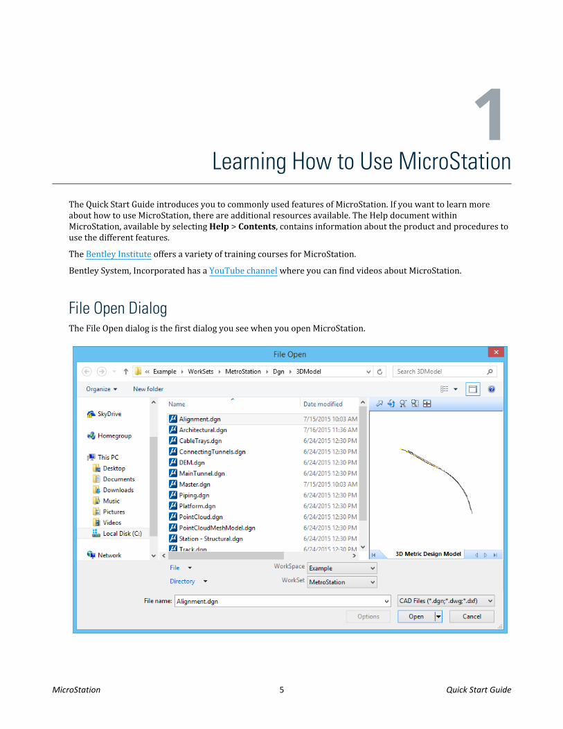
File Open DialogThe File Open dialog is the first dialog you see when you open MicroStation.
MicroStation 5 Quick Start Guide
The New icon, Bentley icon, Folder icon, and Workspace components on the right side of the dialog are notWindows defaults. If you know the Workspace components of the file you want to open, you can navigate to itslocation using User, Project, and Interface. If you do not know details about the file, you can navigate through thefile hierarchy. A DGN file will most likely be found in a DGN folder. Select the QuickStart.dgn file from "...\Workspace\Projects\Examples\General\Dgn". The file displays in the Preview pane; you can see what the filecontains before opening it. Click Open.
Application Window
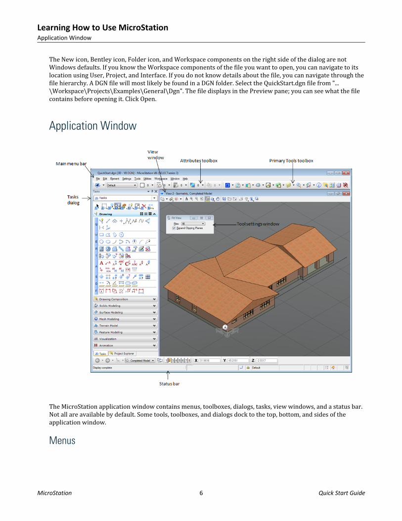
The MicroStation application window contains menus, toolboxes, dialogs, tasks, view windows, and a status bar.Not all are available by default. Some tools, toolboxes, and dialogs dock to the top, bottom, and sides of theapplication window.
Menus
Learning How to Use MicroStationApplication Window
MicroStation 6 Quick Start Guide
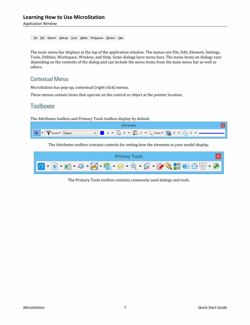
The main menu bar displays at the top of the application window. The menus are File, Edit, Element, Settings,Tools, Utilities, Workspace, Window, and Help. Some dialogs have menu bars. The menu items on dialogs varydepending on the contents of the dialog and can include the menu items from the main menu bar as well asothers.
Contextual MenusMicroStation has pop-up, contextual (right-click) menus.These menus contain items that operate on the control or object at the pointer location.
Toolboxes
The Attributes toolbox and Primary Tools toolbox display by default.
The Attributes toolbox contains controls for setting how the elements in your model display.
The Primary Tools toolbox contains commonly used dialogs and tools.
Learning How to Use MicroStationApplication Window
MicroStation 7 Quick Start Guide
Tasks
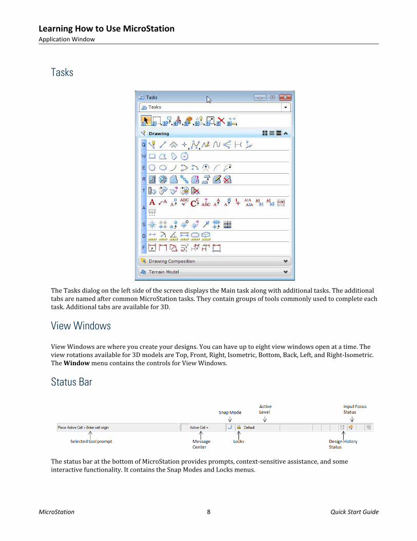
The Tasks dialog on the left side of the screen displays the Main task along with additional tasks. The additionaltabs are named after common MicroStation tasks. They contain groups of tools commonly used to complete eachtask. Additional tabs are available for 3D.
View Windows
View Windows are where you create your designs. You can have up to eight view windows open at a time. Theview rotations available for 3D models are Top, Front, Right, Isometric, Bottom, Back, Left, and Right-Isometric.The Window menu contains the controls for View Windows.
Status Bar
The status bar at the bottom of MicroStation provides prompts, context-sensitive assistance, and someinteractive functionality. It contains the Snap Modes and Locks menus.
Learning How to Use MicroStationApplication Window
MicroStation 8 Quick Start Guide
New FilesNew DGN files are created using seed files. Seed files are DGN file templates that contains preset values such asinitial element parameters, dimensionality (2D or 3D), and working units settings. Several seed files aredelivered with the product. The default seed file is 2D. If you do not set the seed file, the default seed file will beused. When working with MicroStation, units are most likely set in the seed file.
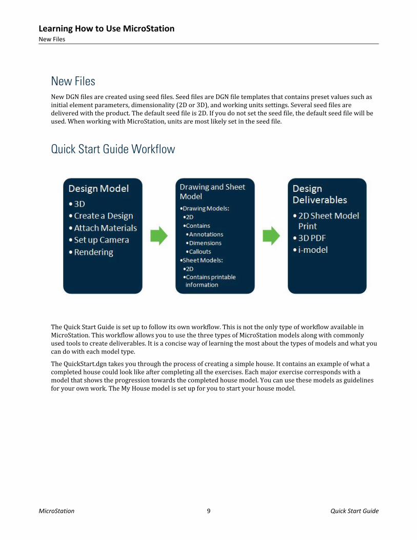
Quick Start Guide Workflow
The Quick Start Guide is set up to follow its own workflow. This is not the only type of workflow available inMicroStation. This workflow allows you to use the three types of MicroStation models along with commonlyused tools to create deliverables. It is a concise way of learning the most about the types of models and what youcan do with each model type.The QuickStart.dgn takes you through the process of creating a simple house. It contains an example of what acompleted house could look like after completing all the exercises. Each major exercise corresponds with amodel that shows the progression towards the completed house model. You can use these models as guidelinesfor your own work. The My House model is set up for you to start your house model.
Learning How to Use MicroStationNew Files
MicroStation 9 Quick Start Guide
2Design Models
A design model consists of design geometry that is added and manipulated using the tools available inMicroStation.
2D or 3D Design ModelsA design model can be either 2D or 3D. Some tools are only available for 3D models.
To View a Completed 3D Design ModelTo correctly create design elements, you must be able to see where they are located within the design model.1. Open QuickStart.dgn.
The model that opens, Completed Model, is a completed 3D design model. One view window is open. You canhave up to eight view windows open at a time. The open view window's view rotation is Isometric.
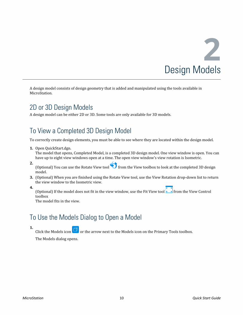
2.(Optional) You can use the Rotate View tool from the View toolbox to look at the completed 3D designmodel.
3. (Optional) When you are finished using the Rotate View tool, use the View Rotation drop-down list to returnthe view window to the Isometric view.
4.(Optional) If the model does not fit in the view window, use the Fit View tool from the View ControltoolboxThe model fits in the view.
To Use the Models Dialog to Open a Model1.
Click the Models icon or the arrow next to the Models icon on the Primary Tools toolbox.The Models dialog opens.
MicroStation 10 Quick Start Guide
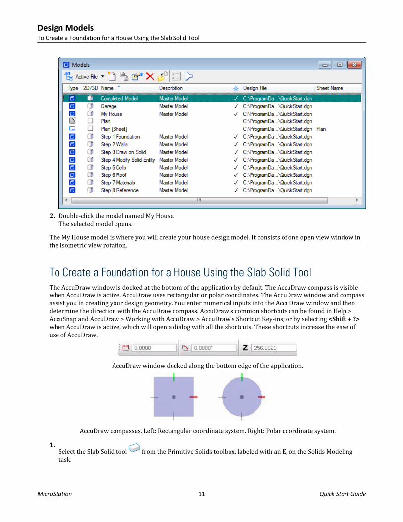
2. Double-click the model named My House.The selected model opens.
The My House model is where you will create your house design model. It consists of one open view window inthe Isometric view rotation.
To Create a Foundation for a House Using the Slab Solid ToolThe AccuDraw window is docked at the bottom of the application by default. The AccuDraw compass is visiblewhen AccuDraw is active. AccuDraw uses rectangular or polar coordinates. The AccuDraw window and compassassist you in creating your design geometry. You enter numerical inputs into the AccuDraw window and thendetermine the direction with the AccuDraw compass. AccuDraw's common shortcuts can be found in Help >AccuSnap and AccuDraw > Working with AccuDraw > AccuDraw's Shortcut Key-ins, or by selecting <Shift + ?>when AccuDraw is active, which will open a dialog with all the shortcuts. These shortcuts increase the ease ofuse of AccuDraw.
AccuDraw window docked along the bottom edge of the application.
AccuDraw compasses. Left: Rectangular coordinate system. Right: Polar coordinate system.1.
Select the Slab Solid tool from the Primitive Solids toolbox, labeled with an E, on the Solids Modelingtask.
Design ModelsTo Create a Foundation for a House Using the Slab Solid Tool
MicroStation 11 Quick Start Guide
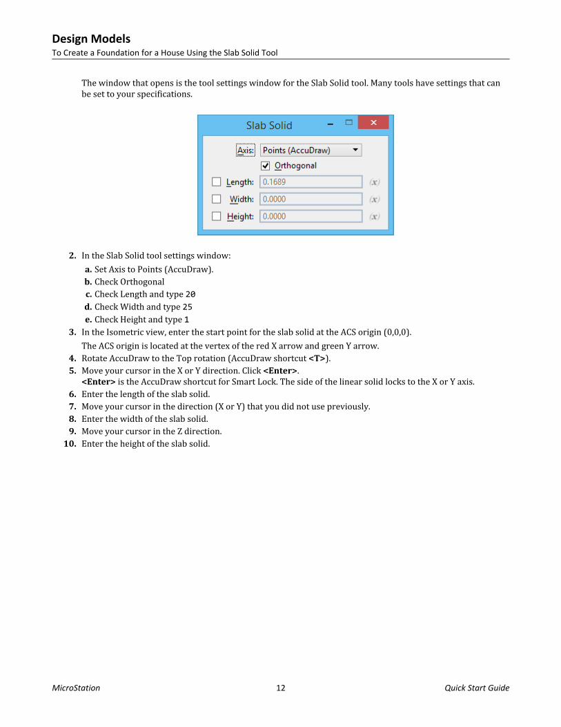
The window that opens is the tool settings window for the Slab Solid tool. Many tools have settings that canbe set to your specifications.
2. In the Slab Solid tool settings window:a. Set Axis to Points (AccuDraw).b. Check Orthogonalc. Check Length and type 20d. Check Width and type 25e. Check Height and type 1
3. In the Isometric view, enter the start point for the slab solid at the ACS origin (0,0,0).The ACS origin is located at the vertex of the red X arrow and green Y arrow.
4. Rotate AccuDraw to the Top rotation (AccuDraw shortcut <T>).5. Move your cursor in the X or Y direction. Click <Enter>.
<Enter> is the AccuDraw shortcut for Smart Lock. The side of the linear solid locks to the X or Y axis.6. Enter the length of the slab solid.7. Move your cursor in the direction (X or Y) that you did not use previously.8. Enter the width of the slab solid.9. Move your cursor in the Z direction.
10. Enter the height of the slab solid.
Design ModelsTo Create a Foundation for a House Using the Slab Solid Tool
MicroStation 12 Quick Start Guide
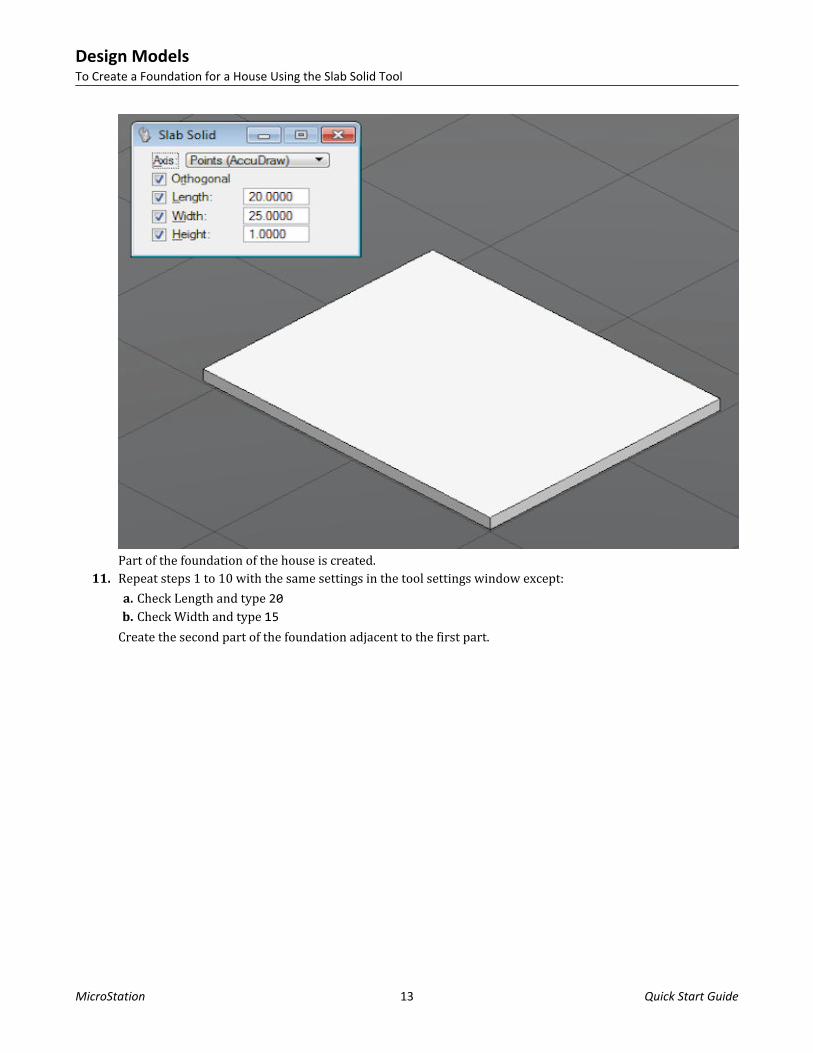
Part of the foundation of the house is created.11. Repeat steps 1 to 10 with the same settings in the tool settings window except:
a. Check Length and type 20b. Check Width and type 15
Create the second part of the foundation adjacent to the first part.
Design ModelsTo Create a Foundation for a House Using the Slab Solid Tool
MicroStation 13 Quick Start Guide
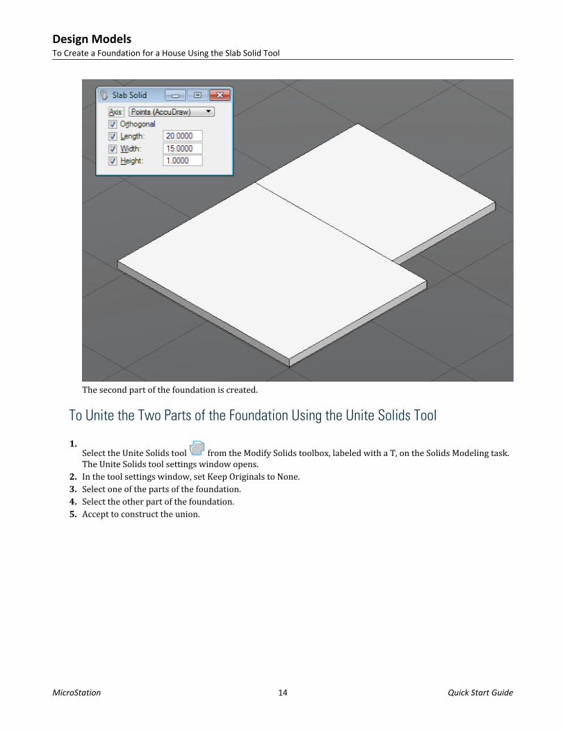
The second part of the foundation is created.
To Unite the Two Parts of the Foundation Using the Unite Solids Tool
1.Select the Unite Solids tool from the Modify Solids toolbox, labeled with a T, on the Solids Modeling task.The Unite Solids tool settings window opens.
2. In the tool settings window, set Keep Originals to None.3. Select one of the parts of the foundation.4. Select the other part of the foundation.5. Accept to construct the union.
Design ModelsTo Create a Foundation for a House Using the Slab Solid Tool
MicroStation 14 Quick Start Guide
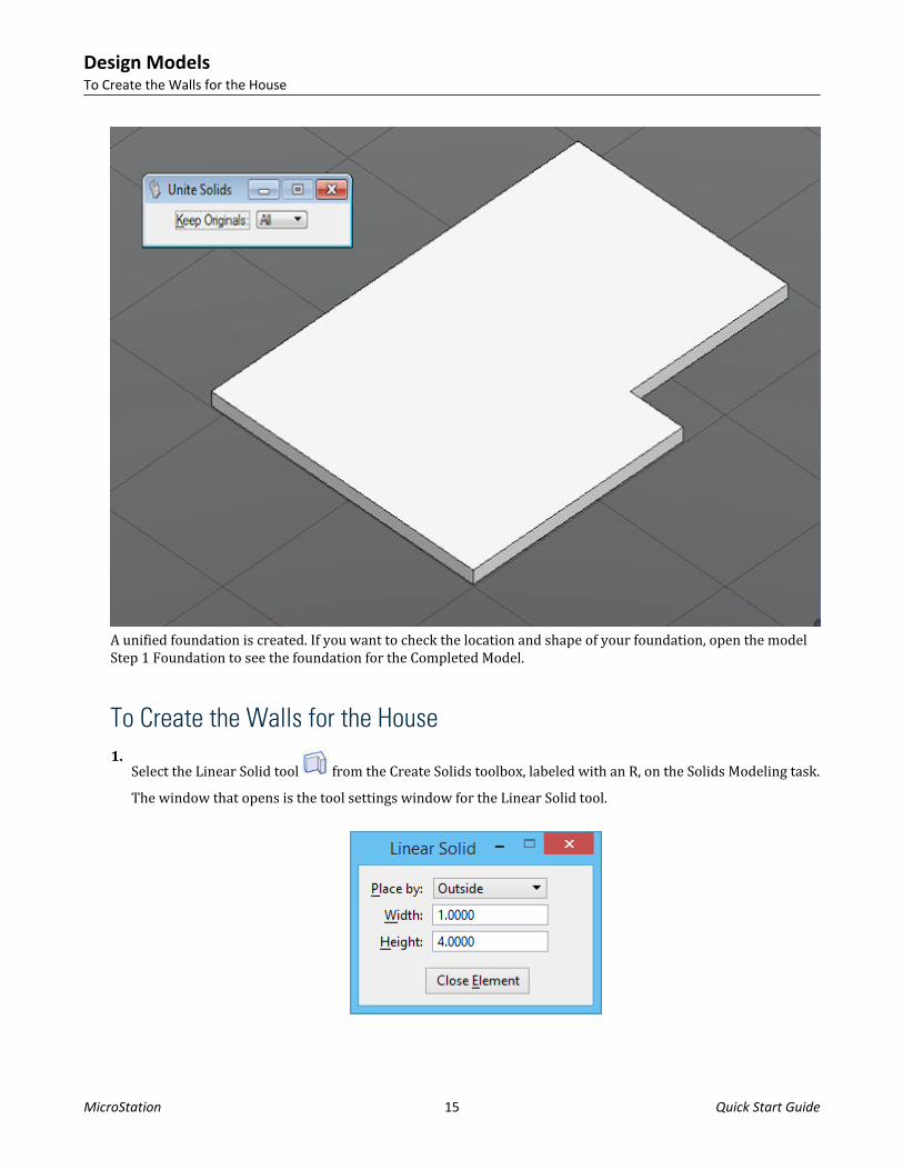
A unified foundation is created. If you want to check the location and shape of your foundation, open the modelStep 1 Foundation to see the foundation for the Completed Model.
To Create the Walls for the House1.
Select the Linear Solid tool from the Create Solids toolbox, labeled with an R, on the Solids Modeling task.The window that opens is the tool settings window for the Linear Solid tool.
Design ModelsTo Create the Walls for the House
MicroStation 15 Quick Start Guide
2. Set the tool settings:a. Place by: Outsideb. Width: 1c. Height: 4
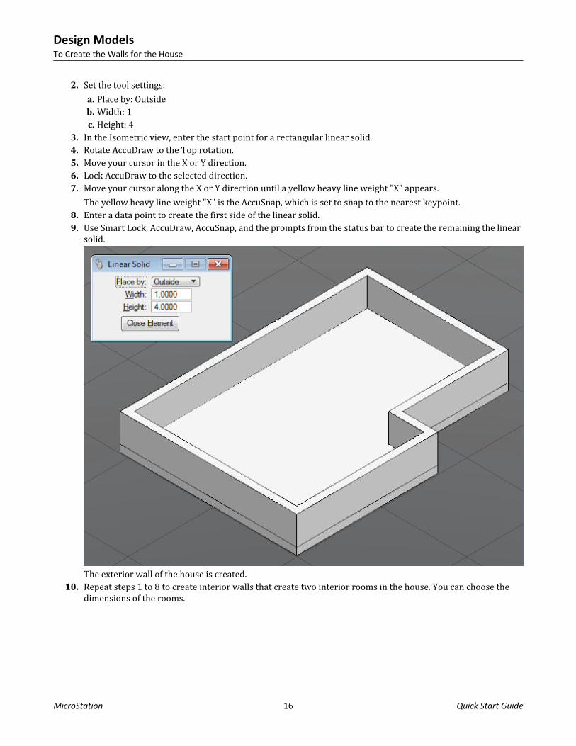
3. In the Isometric view, enter the start point for a rectangular linear solid.4. Rotate AccuDraw to the Top rotation.5. Move your cursor in the X or Y direction.6. Lock AccuDraw to the selected direction.7. Move your cursor along the X or Y direction until a yellow heavy line weight "X" appears.
The yellow heavy line weight "X" is the AccuSnap, which is set to snap to the nearest keypoint.8. Enter a data point to create the first side of the linear solid.9. Use Smart Lock, AccuDraw, AccuSnap, and the prompts from the status bar to create the remaining the linear
solid.
The exterior wall of the house is created.10. Repeat steps 1 to 8 to create interior walls that create two interior rooms in the house. You can choose the
dimensions of the rooms.
Design ModelsTo Create the Walls for the House
MicroStation 16 Quick Start Guide
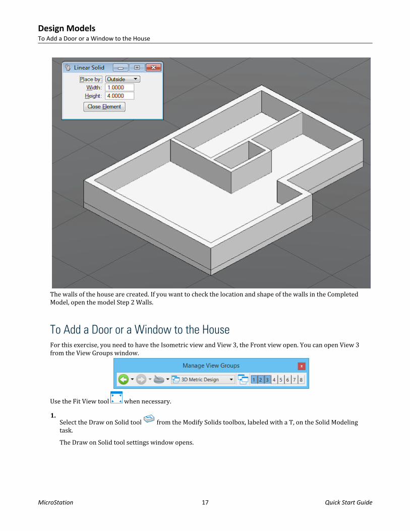
The walls of the house are created. If you want to check the location and shape of the walls in the CompletedModel, open the model Step 2 Walls.
To Add a Door or a Window to the HouseFor this exercise, you need to have the Isometric view and View 3, the Front view open. You can open View 3from the View Groups window.
Use the Fit View tool when necessary.1.
Select the Draw on Solid tool from the Modify Solids toolbox, labeled with a T, on the Solid Modelingtask.The Draw on Solid tool settings window opens.
Design ModelsTo Add a Door or a Window to the House
MicroStation 17 Quick Start Guide
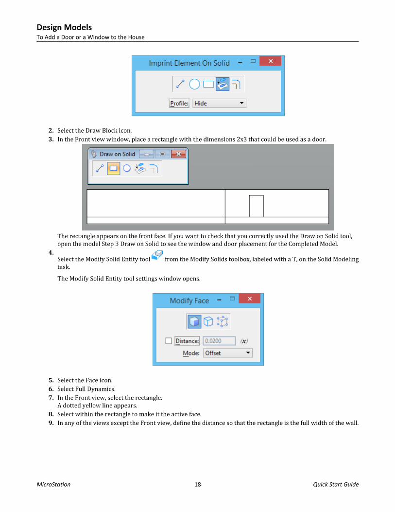
2. Select the Draw Block icon.3. In the Front view window, place a rectangle with the dimensions 2x3 that could be used as a door.
The rectangle appears on the front face. If you want to check that you correctly used the Draw on Solid tool,open the model Step 3 Draw on Solid to see the window and door placement for the Completed Model.
4.Select the Modify Solid Entity tool from the Modify Solids toolbox, labeled with a T, on the Solid Modelingtask.The Modify Solid Entity tool settings window opens.
5. Select the Face icon.6. Select Full Dynamics.7. In the Front view, select the rectangle.
A dotted yellow line appears.8. Select within the rectangle to make it the active face.9. In any of the views except the Front view, define the distance so that the rectangle is the full width of the wall.
Design ModelsTo Add a Door or a Window to the House
MicroStation 18 Quick Start Guide
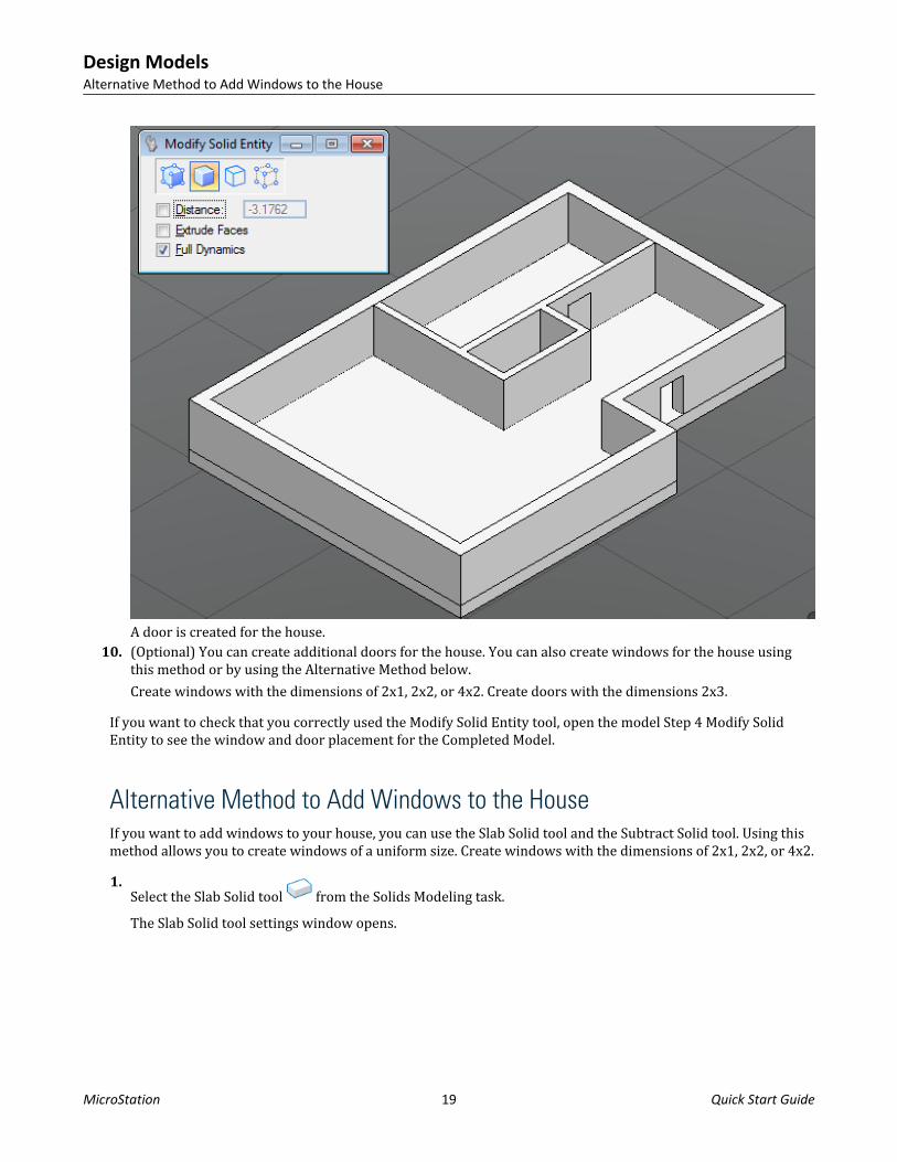
A door is created for the house.10. (Optional) You can create additional doors for the house. You can also create windows for the house using
this method or by using the Alternative Method below.Create windows with the dimensions of 2x1, 2x2, or 4x2. Create doors with the dimensions 2x3.
If you want to check that you correctly used the Modify Solid Entity tool, open the model Step 4 Modify SolidEntity to see the window and door placement for the Completed Model.
Alternative Method to Add Windows to the HouseIf you want to add windows to your house, you can use the Slab Solid tool and the Subtract Solid tool. Using thismethod allows you to create windows of a uniform size. Create windows with the dimensions of 2x1, 2x2, or 4x2.1.
Select the Slab Solid tool from the Solids Modeling task.The Slab Solid tool settings window opens.
Design ModelsAlternative Method to Add Windows to the House
MicroStation 19 Quick Start Guide
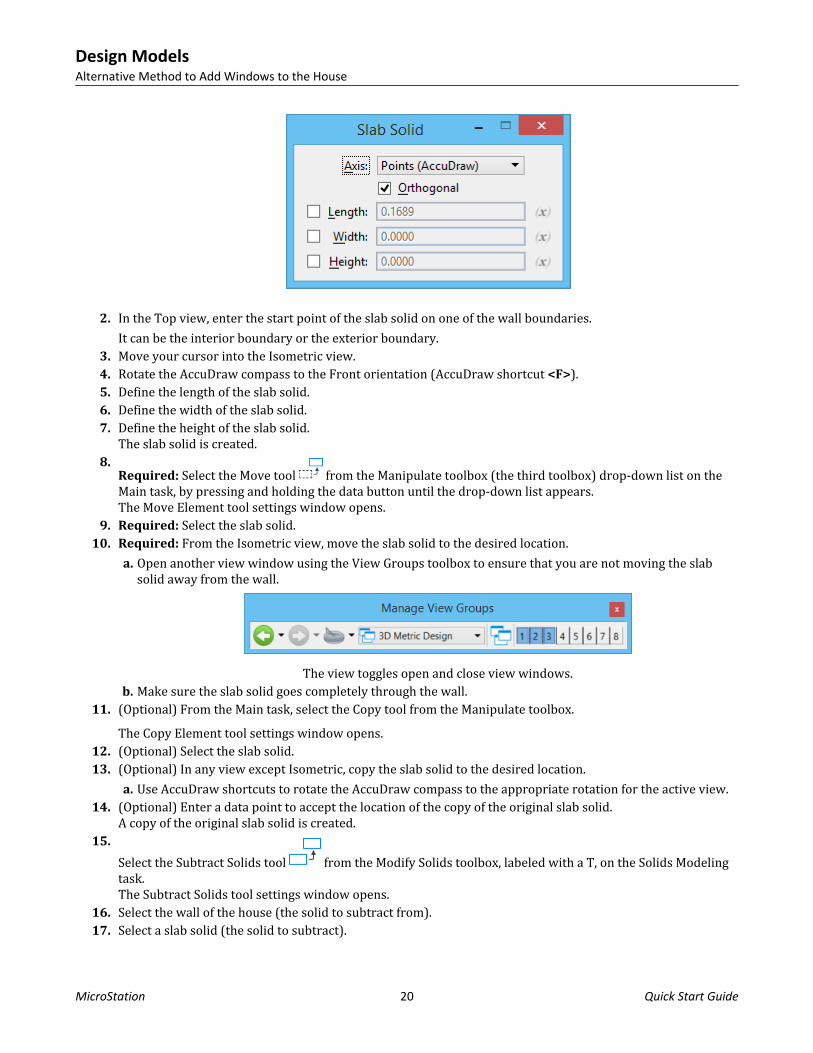
2. In the Top view, enter the start point of the slab solid on one of the wall boundaries.
It can be the interior boundary or the exterior boundary.3. Move your cursor into the Isometric view.4. Rotate the AccuDraw compass to the Front orientation (AccuDraw shortcut <F>).5. Define the length of the slab solid.6. Define the width of the slab solid.7. Define the height of the slab solid.
The slab solid is created.8.
Required: Select the Move tool from the Manipulate toolbox (the third toolbox) drop-down list on theMain task, by pressing and holding the data button until the drop-down list appears.The Move Element tool settings window opens.
9. Required: Select the slab solid.10. Required: From the Isometric view, move the slab solid to the desired location.
a. Open another view window using the View Groups toolbox to ensure that you are not moving the slabsolid away from the wall.
The view toggles open and close view windows.b. Make sure the slab solid goes completely through the wall.
11. (Optional) From the Main task, select the Copy tool from the Manipulate toolbox.The Copy Element tool settings window opens.
12. (Optional) Select the slab solid.13. (Optional) In any view except Isometric, copy the slab solid to the desired location.
a. Use AccuDraw shortcuts to rotate the AccuDraw compass to the appropriate rotation for the active view.14. (Optional) Enter a data point to accept the location of the copy of the original slab solid.
A copy of the original slab solid is created.15.
Select the Subtract Solids tool from the Modify Solids toolbox, labeled with a T, on the Solids Modelingtask.The Subtract Solids tool settings window opens.
16. Select the wall of the house (the solid to subtract from).17. Select a slab solid (the solid to subtract).
Design ModelsAlternative Method to Add Windows to the House
MicroStation 20 Quick Start Guide
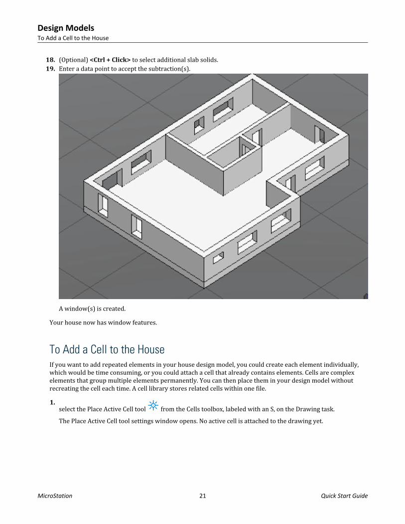
18. (Optional) <Ctrl + Click> to select additional slab solids.19. Enter a data point to accept the subtraction(s).
A window(s) is created.Your house now has window features.
To Add a Cell to the HouseIf you want to add repeated elements in your house design model, you could create each element individually,which would be time consuming, or you could attach a cell that already contains elements. Cells are complexelements that group multiple elements permanently. You can then place them in your design model withoutrecreating the cell each time. A cell library stores related cells within one file.1.
select the Place Active Cell tool from the Cells toolbox, labeled with an S, on the Drawing task.The Place Active Cell tool settings window opens. No active cell is attached to the drawing yet.
Design ModelsTo Add a Cell to the House
MicroStation 21 Quick Start Guide
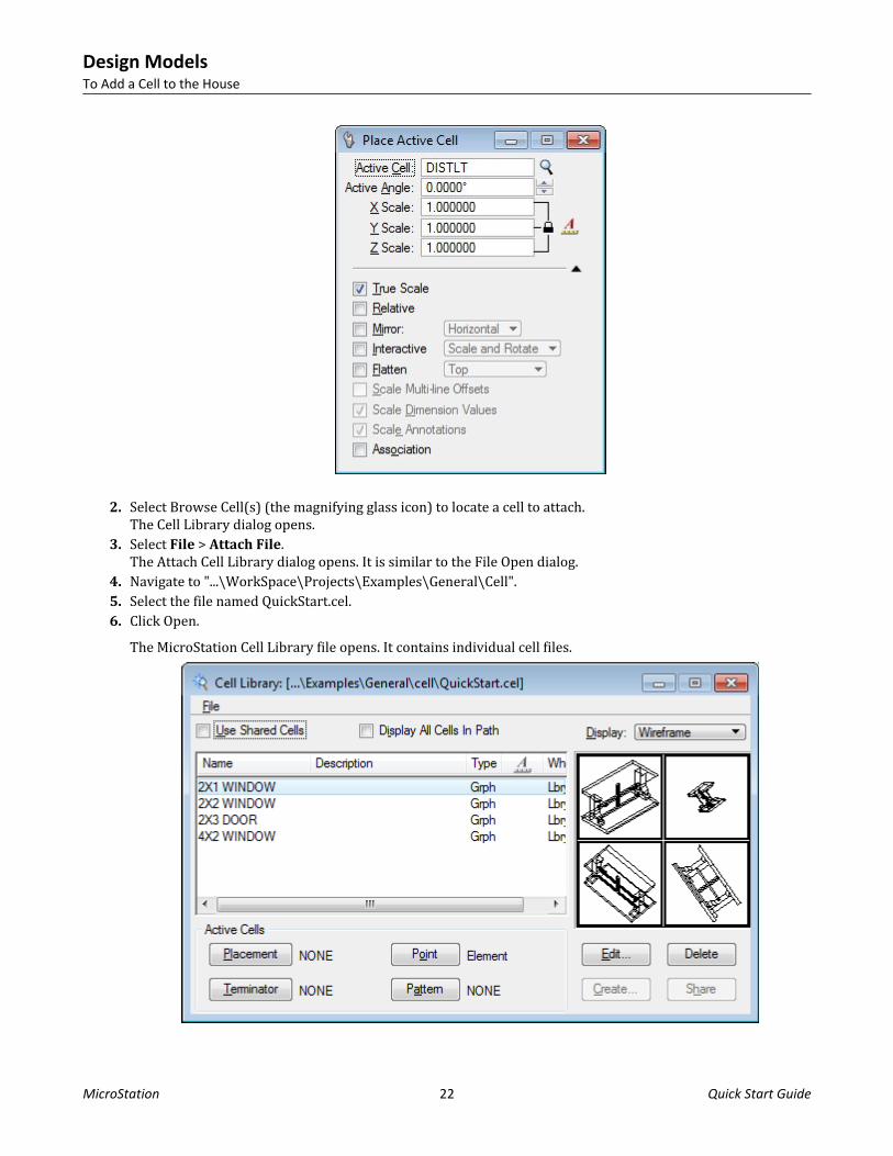
2. Select Browse Cell(s) (the magnifying glass icon) to locate a cell to attach.
The Cell Library dialog opens.3. Select File > Attach File.
The Attach Cell Library dialog opens. It is similar to the File Open dialog.4. Navigate to "...\WorkSpace\Projects\Examples\General\Cell".5. Select the file named QuickStart.cel.6. Click Open.
The MicroStation Cell Library file opens. It contains individual cell files.
Design ModelsTo Add a Cell to the House
MicroStation 22 Quick Start Guide
7. From the list box, select a cell to place in your house design model file.The cells contained in this cell library are windows.
8. In the Active Cells section of the Cell Library dialog, click Placement.The selected cell file name displays next to Placement.
9. Close the Cell Library dialog.10. On the Place Active Cell dialog, turn on the Interactive check box and set it to Scale and Rotate.11. Place the window cell in your house design model.
If you want to check the placement of the cells, open the model Step 5 Cells to see the cells for the CompletedModel.
To Create a Roof for the House1.
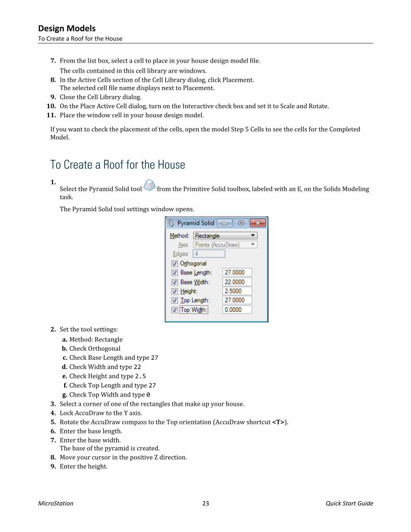
Select the Pyramid Solid tool from the Primitive Solid toolbox, labeled with an E, on the Solids Modelingtask.The Pyramid Solid tool settings window opens.
2. Set the tool settings:a. Method: Rectangleb. Check Orthogonalc. Check Base Length and type 27d. Check Width and type 22e. Check Height and type 2.5f. Check Top Length and type 27g. Check Top Width and type 0
3. Select a corner of one of the rectangles that make up your house.4. Lock AccuDraw to the Y axis.5. Rotate the AccuDraw compass to the Top orientation (AccuDraw shortcut <T>).6. Enter the base length.7. Enter the base width.
The base of the pyramid is created.8. Move your cursor in the positive Z direction.9. Enter the height.
Design ModelsTo Create a Roof for the House
MicroStation 23 Quick Start Guide
10. Enter the top width.A pyramid solid is created.
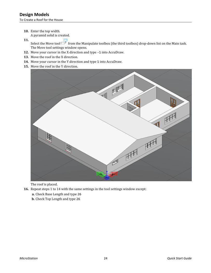
11.Select the Move tool from the Manipulate toolbox (the third toolbox) drop-down list on the Main task.The Move tool settings window opens.
12. Move your cursor in the X direction and type -1 into AccuDraw.13. Move the roof in the X direction.14. Move your cursor in the Y direction and type 1 into AccuDraw.15. Move the roof in the Y direction.
The roof is placed.16. Repeat steps 1 to 14 with the same settings in the tool settings window except:
a. Check Base Length and type 26b. Check Top Length and type 26
Design ModelsTo Create a Roof for the House
MicroStation 24 Quick Start Guide
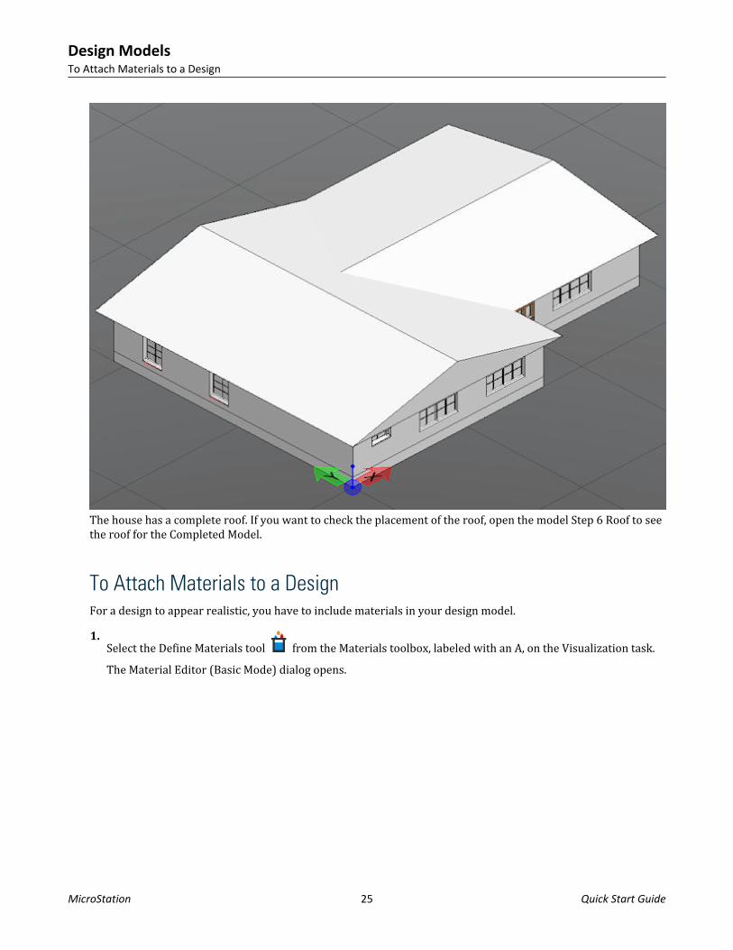
The house has a complete roof. If you want to check the placement of the roof, open the model Step 6 Roof to seethe roof for the Completed Model.
To Attach Materials to a DesignFor a design to appear realistic, you have to include materials in your design model.1.
Select the Define Materials tool from the Materials toolbox, labeled with an A, on the Visualization task.The Material Editor (Basic Mode) dialog opens.
Design ModelsTo Attach Materials to a Design
MicroStation 25 Quick Start Guide
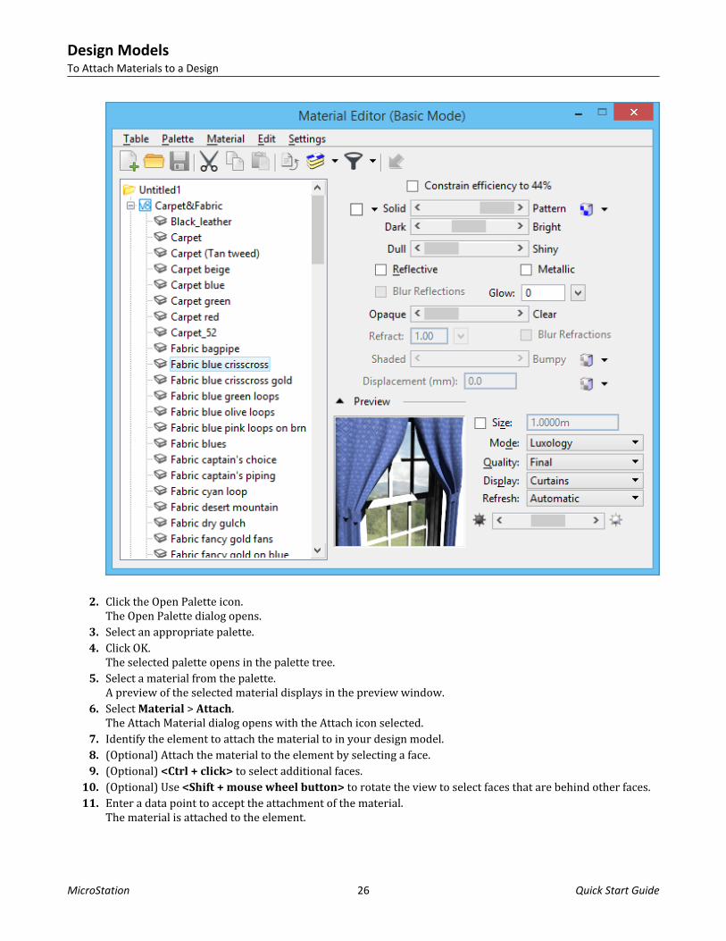
2. Click the Open Palette icon.
The Open Palette dialog opens.3. Select an appropriate palette.4. Click OK.
The selected palette opens in the palette tree.5. Select a material from the palette.
A preview of the selected material displays in the preview window.6. Select Material > Attach.
The Attach Material dialog opens with the Attach icon selected.7. Identify the element to attach the material to in your design model.8. (Optional) Attach the material to the element by selecting a face.9. (Optional) <Ctrl + click> to select additional faces.
10. (Optional) Use <Shift + mouse wheel button> to rotate the view to select faces that are behind other faces.11. Enter a data point to accept the attachment of the material.
The material is attached to the element.
Design ModelsTo Attach Materials to a Design
MicroStation 26 Quick Start Guide
12. Use the Material Editor dialog and the Attach Material dialog to attach materials to the house elementswithout attached materials.
If you want to see the materials used for the Completed Model, open the model Step 7 Materials.
To Get Information About an Element1. Select Element Information from the Primary Tools toolbox.2. Select the Element Selection tool from the Main task.3. Select an element that is part of your house.
The Element Information dialog opens. Information about the selected element displays.
Design ModelsTo Get Information About an Element
MicroStation 27 Quick Start Guide
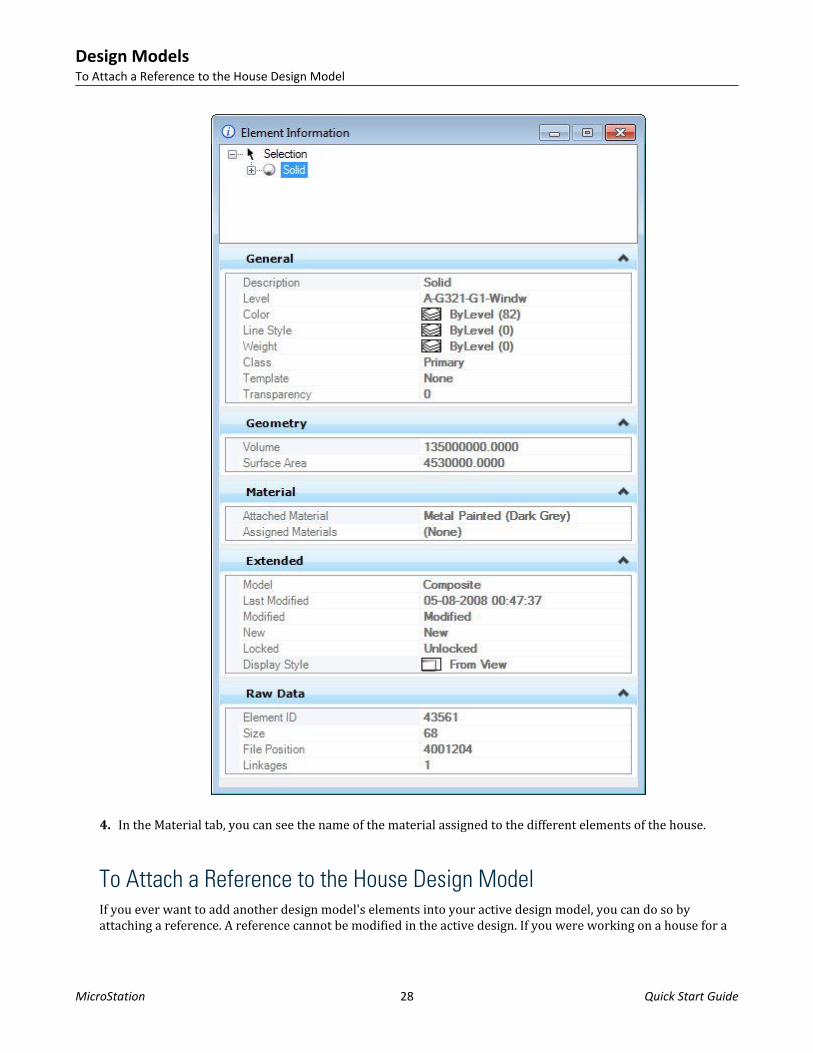
4. In the Material tab, you can see the name of the material assigned to the different elements of the house.
To Attach a Reference to the House Design ModelIf you ever want to add another design model's elements into your active design model, you can do so byattaching a reference. A reference cannot be modified in the active design. If you were working on a house for a
Design ModelsTo Attach a Reference to the House Design Model
MicroStation 28 Quick Start Guide
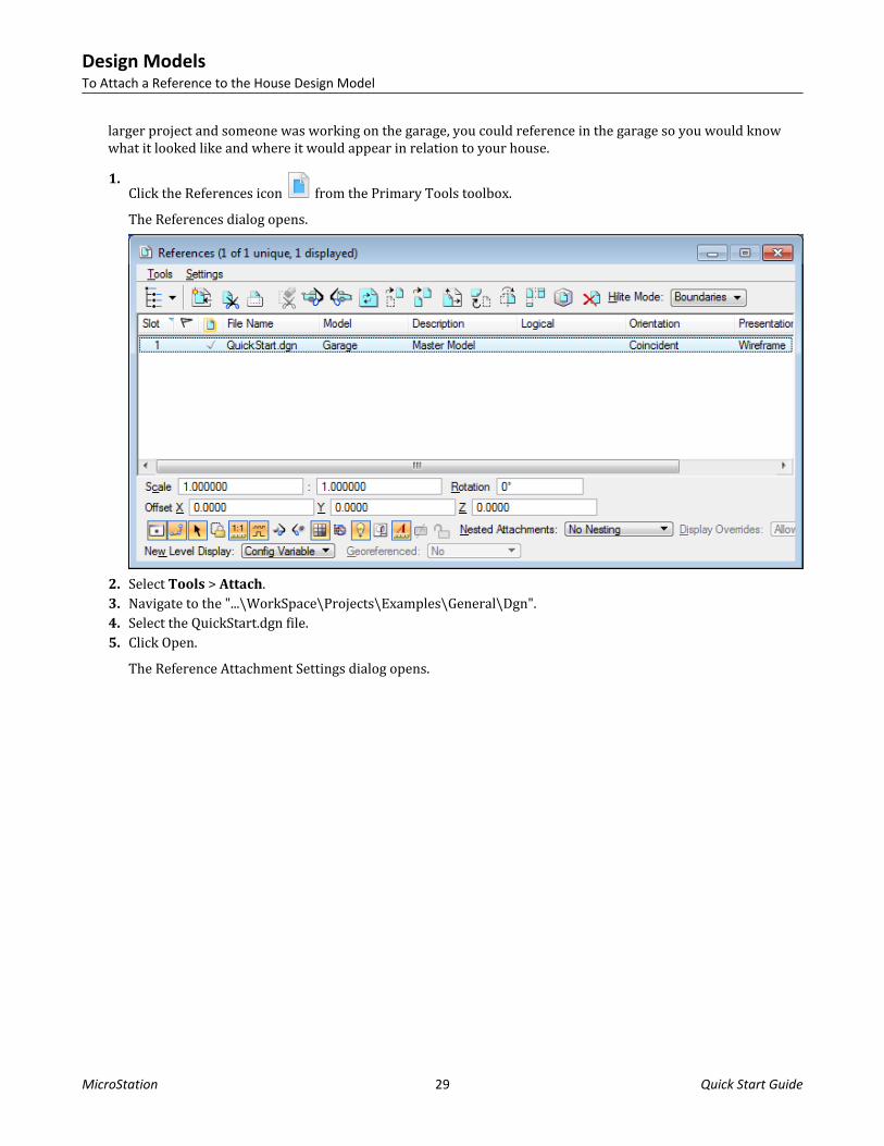
larger project and someone was working on the garage, you could reference in the garage so you would knowwhat it looked like and where it would appear in relation to your house.1.
Click the References icon from the Primary Tools toolbox.The References dialog opens.
2. Select Tools > Attach.3. Navigate to the "...\WorkSpace\Projects\Examples\General\Dgn".4. Select the QuickStart.dgn file.5. Click Open.
The Reference Attachment Settings dialog opens.
Design ModelsTo Attach a Reference to the House Design Model
MicroStation 29 Quick Start Guide
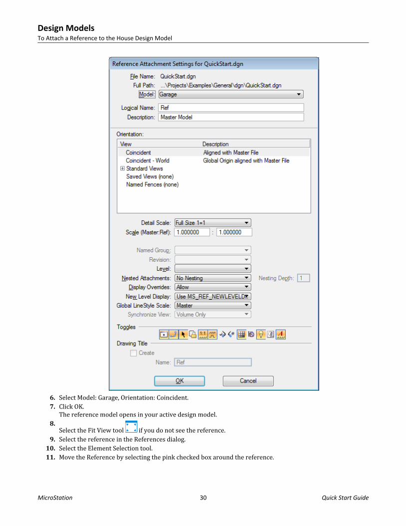
6. Select Model: Garage, Orientation: Coincident.7. Click OK.
The reference model opens in your active design model.8.
Select the Fit View tool if you do not see the reference.9. Select the reference in the References dialog.
10. Select the Element Selection tool.11. Move the Reference by selecting the pink checked box around the reference.
Design ModelsTo Attach a Reference to the House Design Model
MicroStation 30 Quick Start Guide
If there are any changes made to the garage design model, changes will reflect in your house design model.If you need to edit the reference, select Tools > Exchange from the References dialog.
If you want to check the location of the reference, open the model Step 8 Reference to see the reference of thegarage in the Completed Model.
To Turn Off a LevelYour house and the garage reference exist on two levels in the design model. Levels are analogous to transparentoverlays. In different combinations they make it easier to see parts of a model. If you turn off a level, the designelements on that level do not display.Note: It is suggested that you use multiple levels for creating model elements so you do not have an entireproject on the default level.
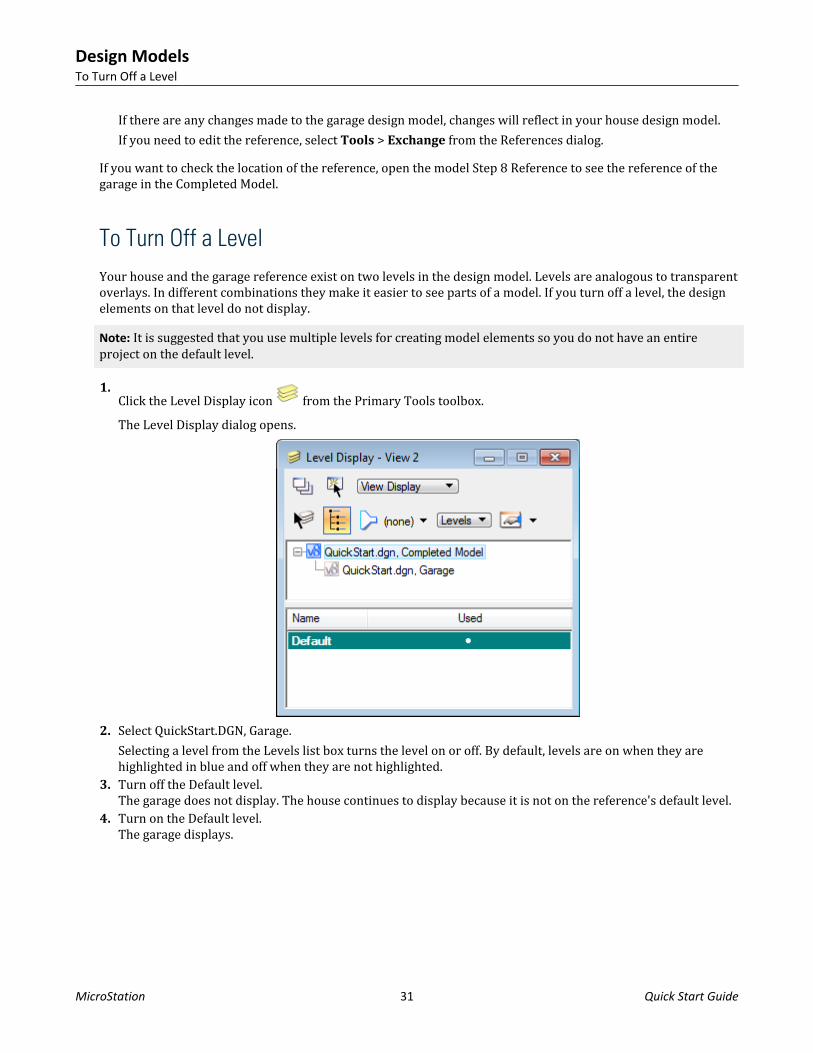
1.Click the Level Display icon from the Primary Tools toolbox.The Level Display dialog opens.
2. Select QuickStart.DGN, Garage.Selecting a level from the Levels list box turns the level on or off. By default, levels are on when they arehighlighted in blue and off when they are not highlighted.
3. Turn off the Default level.The garage does not display. The house continues to display because it is not on the reference's default level.
4. Turn on the Default level.The garage displays.
Design ModelsTo Turn Off a Level
MicroStation 31 Quick Start Guide
3Creating Drawing Models and Sheet Models
A drawing model stores information from different design models in one central location. It is always 2D. Adrawing model is where you would store annotations, dimensions, and callouts. Its default background is gray. Asheet model is like a sheet of drafting paper. It contains printable information for your designs.
Creating a Drawing ModelYou can create a drawing model that references in complete design models or parts of a design model.
Sheet Models and ReferencesSheet models can have references attached containing design and drawing model information. A design can bereferenced by multiple sheet models that use different drawing models; therefore, when the design modelchanges the different sheet models will reflect the change because of the attached references. If you did not usereferences, you would have to have a different design model for each sheet model. Creating multiple copies ofthe same design model and updating each with every change is unnecessary when you use references.
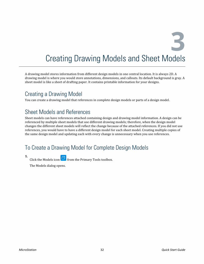
To Create a Drawing Model for Complete Design Models1.
Click the Models icon from the Primary Tools toolbox.The Models dialog opens.
MicroStation 32 Quick Start Guide
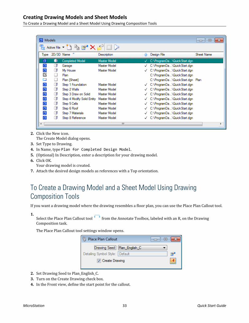
2. Click the New icon.The Create Model dialog opens.
3. Set Type to Drawing.4. In Name, type Plan for Completed Design Model.5. (Optional) In Description, enter a description for your drawing model.6. Click OK.
Your drawing model is created.7. Attach the desired design models as references with a Top orientation.
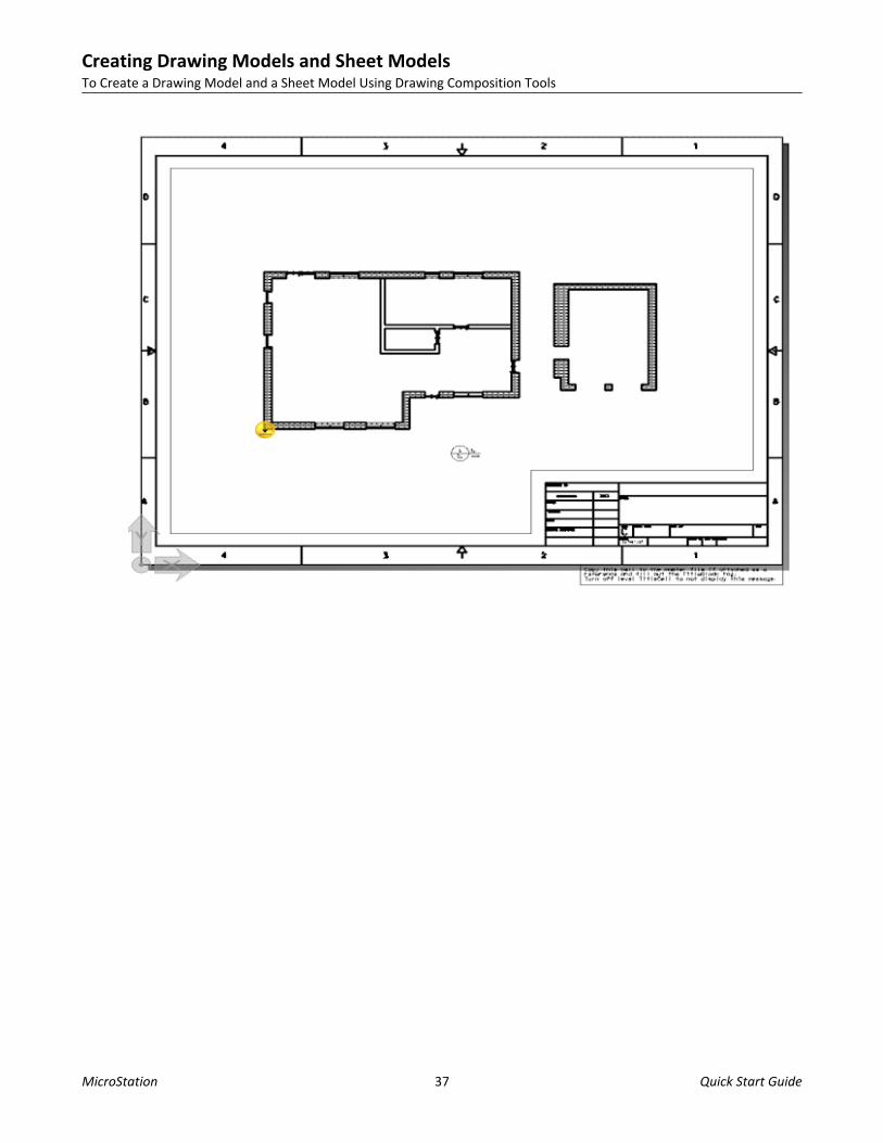
To Create a Drawing Model and a Sheet Model Using DrawingComposition ToolsIf you want a drawing model where the drawing resembles a floor plan, you can use the Place Plan Callout tool.1.
Select the Place Plan Callout tool from the Annotate Toolbox, labeled with an R, on the DrawingComposition task.The Place Plan Callout tool settings window opens.
2. Set Drawing Seed to Plan_English_C.3. Turn on the Create Drawing check box.4. In the Front view, define the start point for the callout.
Creating Drawing Models and Sheet ModelsTo Create a Drawing Model and a Sheet Model Using Drawing Composition Tools
MicroStation 33 Quick Start Guide
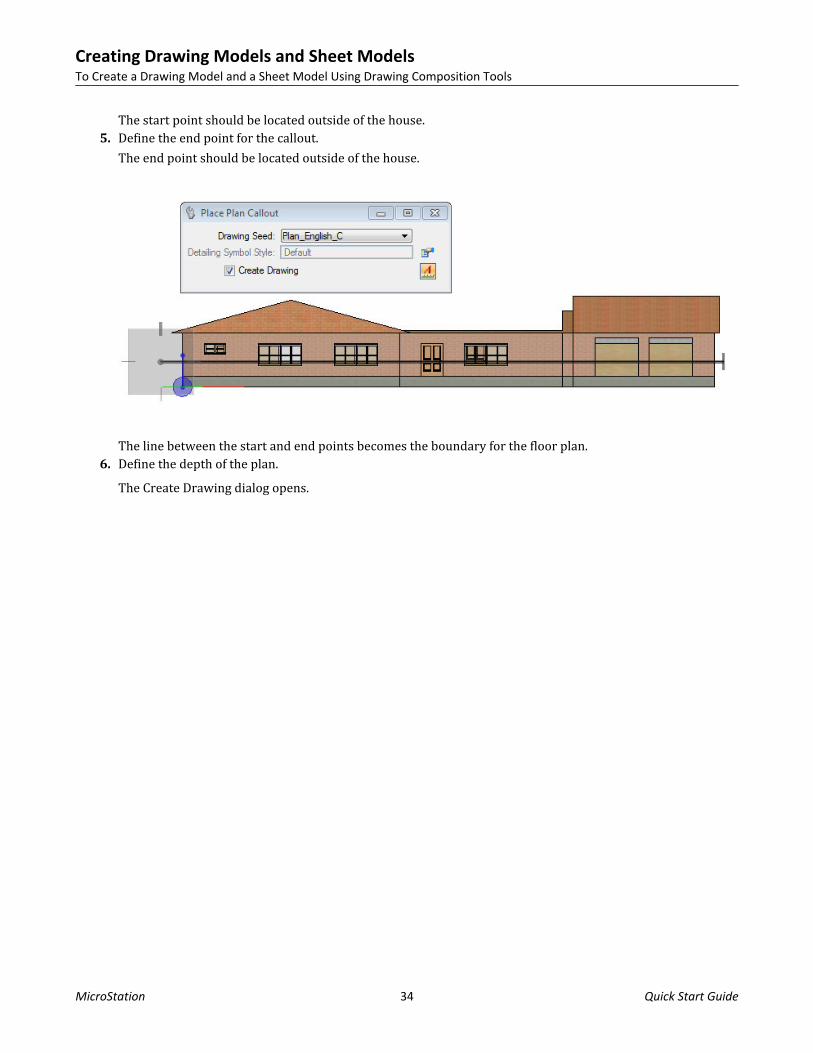
The start point should be located outside of the house.5. Define the end point for the callout.
The end point should be located outside of the house.
The line between the start and end points becomes the boundary for the floor plan.
6. Define the depth of the plan.The Create Drawing dialog opens.
Creating Drawing Models and Sheet ModelsTo Create a Drawing Model and a Sheet Model Using Drawing Composition Tools
MicroStation 34 Quick Start Guide
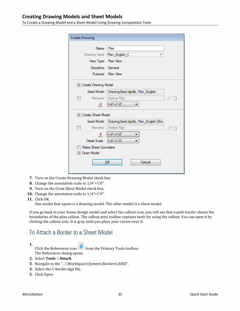
7. Turn on the Create Drawing Model check box.8. Change the annotation scale to 1/4"=1'0".9. Turn on the Creat Sheet Model check box.
10. Change the annotation scale to 1/4"=1'0".11. Click OK.
One model that opens is a drawing model. The other model is a sheet model.If you go back to your house design model and select the callout icon, you will see that a pink border shows theboundaries of the plan callout. The callout mini toolbar contains tools for using the callout. You can open it byclicking the callout icon. It is gray until you place your cursor over it.
To Attach a Border to a Sheet Model
1.Click the References icon from the Primary Tools toolbox.The References dialog opens.
2. Select Tools > Attach.3. Navigate to the "…\WorkSpace\System\Borders\ANSI".4. Select the C-border.dgn file.5. Click Open.
Creating Drawing Models and Sheet ModelsTo Create a Drawing Model and a Sheet Model Using Drawing Composition Tools
MicroStation 35 Quick Start Guide
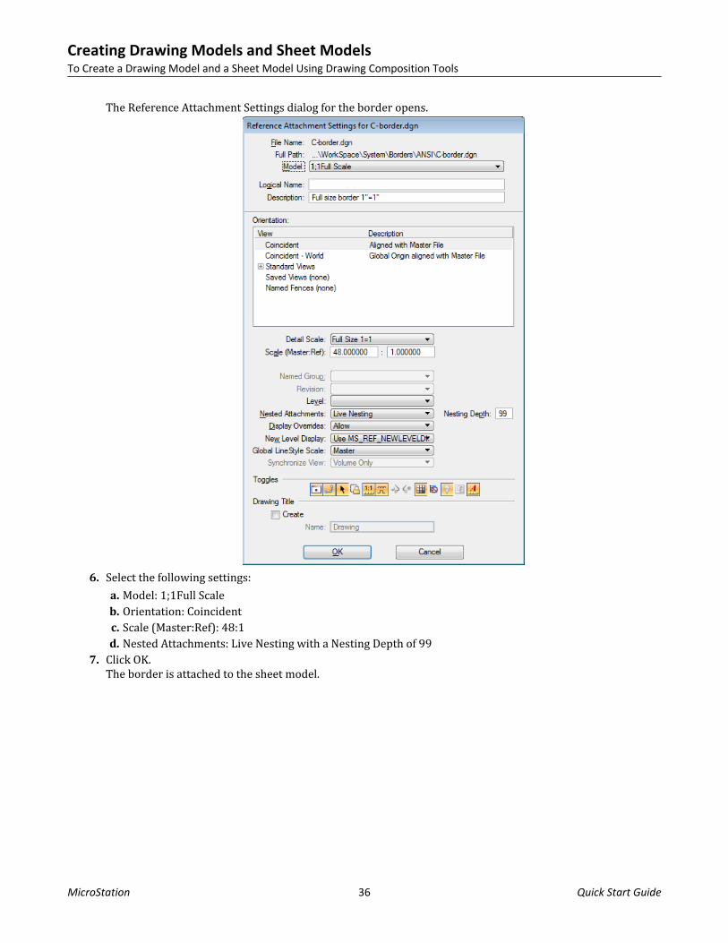
The Reference Attachment Settings dialog for the border opens.
6. Select the following settings:a. Model: 1;1Full Scaleb. Orientation: Coincidentc. Scale (Master:Ref): 48:1d. Nested Attachments: Live Nesting with a Nesting Depth of 99
7. Click OK.The border is attached to the sheet model.
Creating Drawing Models and Sheet ModelsTo Create a Drawing Model and a Sheet Model Using Drawing Composition Tools
MicroStation 36 Quick Start Guide
Creating Drawing Models and Sheet ModelsTo Create a Drawing Model and a Sheet Model Using Drawing Composition Tools
MicroStation 37 Quick Start Guide
4Rendering a Completed Design
Rendering with the Luxology Render DialogA completed design that needs to appear as it actually would in an environment can be rendered to achieve thecorrect real-world look and feel. You can create a rendering of your design using different materials, lighting,and camera settings. Rendering is the process of depicting a 3D model through the display of shaded surfaces.You can render your completed designs to give them a real world appearance or an abstract appearance. TheLuxology Render dialog is where you adjust the settings for your render.
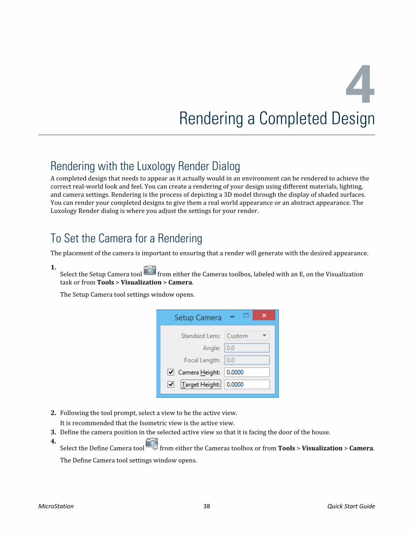
To Set the Camera for a RenderingThe placement of the camera is important to ensuring that a render will generate with the desired appearance.1.
Select the Setup Camera tool from either the Cameras toolbox, labeled with an E, on the Visualizationtask or from Tools > Visualization > Camera.The Setup Camera tool settings window opens.
2. Following the tool prompt, select a view to be the active view.
It is recommended that the Isometric view is the active view.3. Define the camera position in the selected active view so that it is facing the door of the house.4.
Select the Define Camera tool from either the Cameras toolbox or from Tools > Visualization > Camera.The Define Camera tool settings window opens.
MicroStation 38 Quick Start Guide
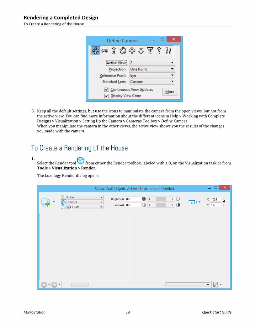
5. Keep all the default settings, but use the icons to manipulate the camera from the open views, but not from
the active view. You can find more information about the different icons in Help > Working with CompleteDesigns > Visualization > Setting Up the Camera > Cameras Toolbox > Define Camera.When you manipulate the camera in the other views, the active view shows you the results of the changesyou made with the camera.
To Create a Rendering of the House1.
Select the Render tool from either the Render toolbox, labeled with a Q, on the Visualization task or fromTools > Visualization > Render.The Luxology Render dialog opens.
Rendering a Completed DesignTo Create a Rendering of the House
MicroStation 39 Quick Start Guide
2. Click the View icon.
The View drop-down menu opens.3. Select the view number for the Isometric view.4. Click the Luxology Render Settings icon drop-down arrow.5. Select Interior Good.6. Click the Luxology Environment Settings icon drop-down arrow.7. Select Physical Sky.8. Click the Begin Luxology Render icon.
The Luxology render starts.When the Luxology render is complete, a realistic rendering of your house design model is created.
Rendering a Completed DesignTo Create a Rendering of the House
MicroStation 40 Quick Start Guide
5Creating Deliverables
Completed designs can be formatted into deliverables that can combine design information with the correctdisplay method. Examples of deliverables you can create in MicroStation are prints of 2D sheet models, 3D PDFsand i-models.
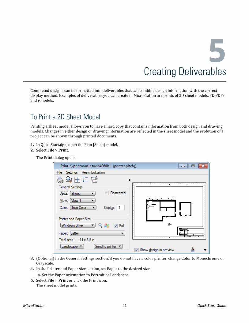
To Print a 2D Sheet ModelPrinting a sheet model allows you to have a hard copy that contains information from both design and drawingmodels. Changes in either design or drawing information are reflected in the sheet model and the evolution of aproject can be shown through printed documents.1. In QuickStart.dgn, open the Plan [Sheet] model.2. Select File > Print.
The Print dialog opens.
3. (Optional) In the General Settings section, if you do not have a color printer, change Color to Monochrome orGrayscale.
4. In the Printer and Paper size section, set Paper to the desired size.a. Set the Paper orientation to Portrait or Landscape.
5. Select File > Print or click the Print icon.The sheet model prints.
MicroStation 41 Quick Start Guide
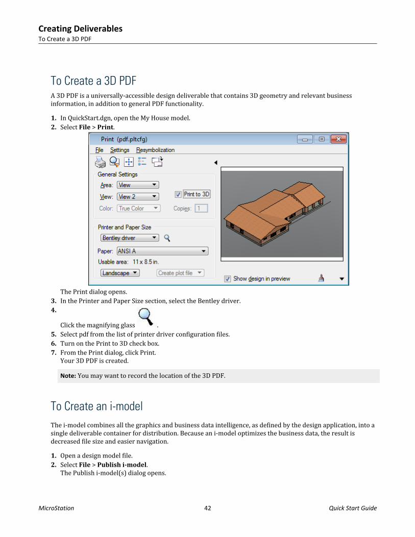
To Create a 3D PDFA 3D PDF is a universally-accessible design deliverable that contains 3D geometry and relevant businessinformation, in addition to general PDF functionality.1. In QuickStart.dgn, open the My House model.2. Select File > Print.
The Print dialog opens.3. In the Printer and Paper Size section, select the Bentley driver.4.
Click the magnifying glass .5. Select pdf from the list of printer driver configuration files.6. Turn on the Print to 3D check box.7. From the Print dialog, click Print.
Your 3D PDF is created.Note: You may want to record the location of the 3D PDF.
To Create an i-modelThe i-model combines all the graphics and business data intelligence, as defined by the design application, into asingle deliverable container for distribution. Because an i-model optimizes the business data, the result isdecreased file size and easier navigation.1. Open a design model file.2. Select File > Publish i-model.
The Publish i-model(s) dialog opens.
Creating DeliverablesTo Create a 3D PDF
MicroStation 42 Quick Start Guide
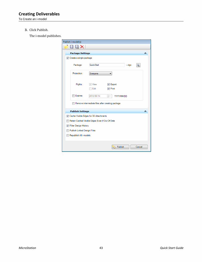
3. Click Publish.The i-model publishes.
Creating DeliverablesTo Create an i-model
MicroStation 43 Quick Start Guide
6Additional Resources
Key Concepts and ToolsThe Key Concepts and Tools resource contains information about important features and tools that were notdiscussed in the body of the Quick Start Guide. For each topic it gives a short description, the location inMicroStation and how to open it, and where to find information about it in the Help.
AccuSnap
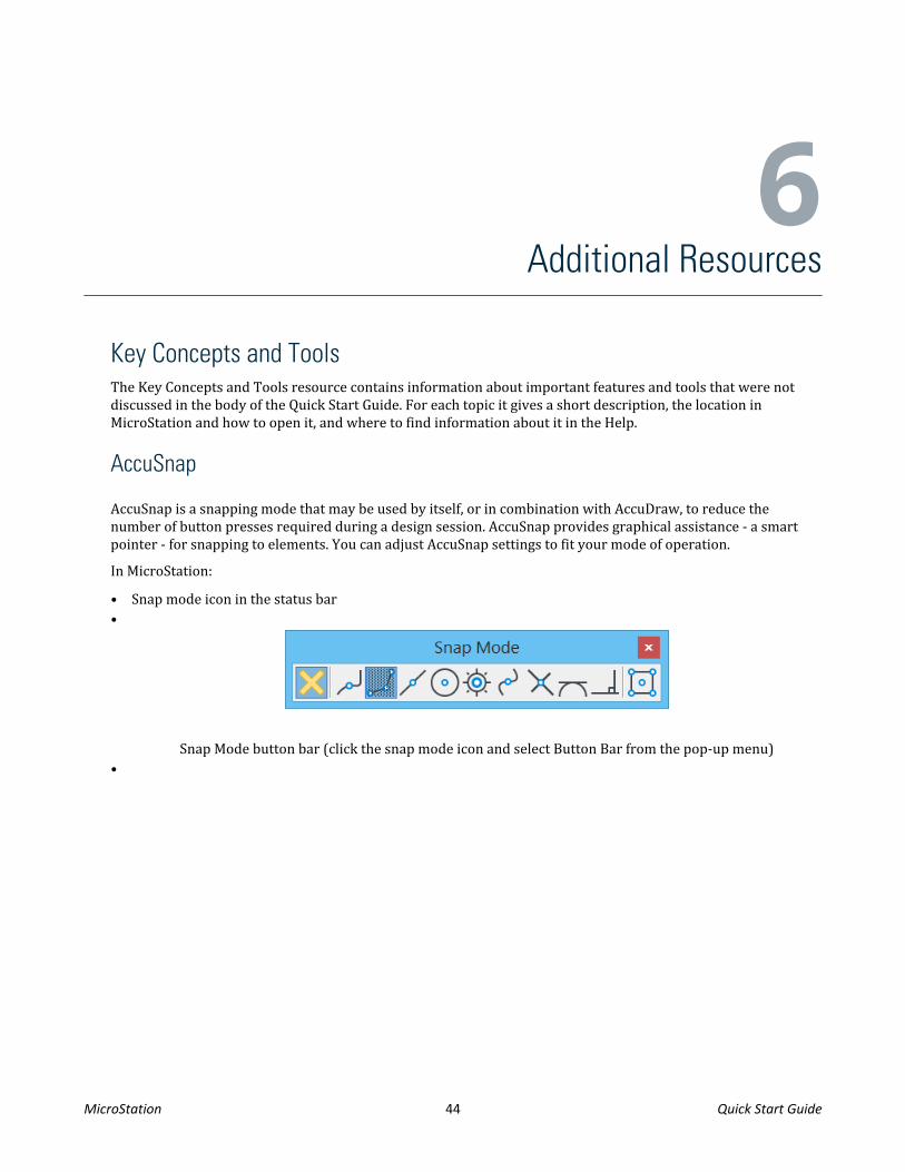
AccuSnap is a snapping mode that may be used by itself, or in combination with AccuDraw, to reduce thenumber of button presses required during a design session. AccuSnap provides graphical assistance - a smartpointer - for snapping to elements. You can adjust AccuSnap settings to fit your mode of operation.In MicroStation:• Snap mode icon in the status bar•
Snap Mode button bar (click the snap mode icon and select Button Bar from the pop-up menu)
•
MicroStation 44 Quick Start Guide
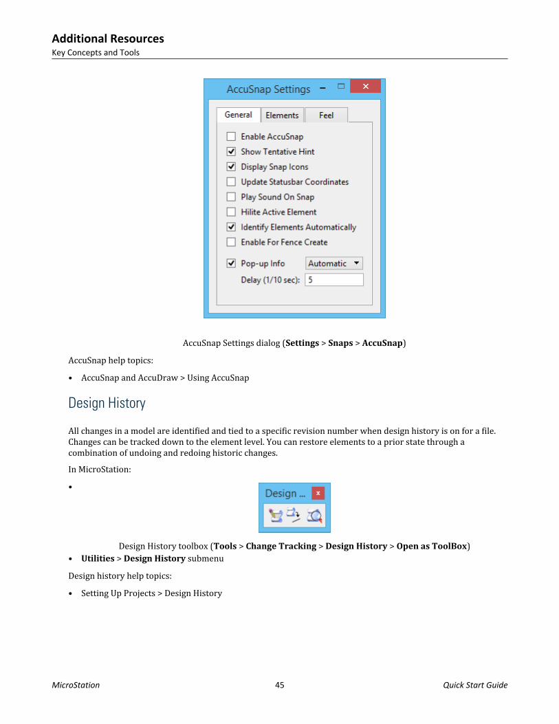
AccuSnap Settings dialog (Settings > Snaps > AccuSnap)
AccuSnap help topics:• AccuSnap and AccuDraw > Using AccuSnap
Design History
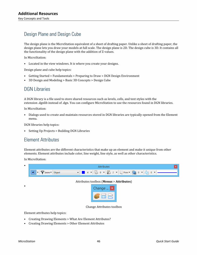
All changes in a model are identified and tied to a specific revision number when design history is on for a file.Changes can be tracked down to the element level. You can restore elements to a prior state through acombination of undoing and redoing historic changes.In MicroStation:•
Design History toolbox (Tools > Change Tracking > Design History > Open as ToolBox)• Utilities > Design History submenuDesign history help topics:• Setting Up Projects > Design History
Additional ResourcesKey Concepts and Tools
MicroStation 45 Quick Start Guide
Design Plane and Design Cube
The design plane is the MicroStation equivalent of a sheet of drafting paper. Unlike a sheet of drafting paper, thedesign plane lets you draw your models at full scale. The design plane is 2D. The design cube is 3D. It contains allthe functionality of the design plane with the addition of Z-values.In MicroStation:• Located in the view windows. It is where you create your designs.Design plane and cube help topics:• Getting Started > Fundamentals > Preparing to Draw > DGN Design Environment• 3D Design and Modeling > Basic 3D Concepts > Design Cube
DGN Libraries
A DGN library is a file used to store shared resources such as levels, cells, and text styles with theextension .dgnlib instead of .dgn. You can configure MicroStation to use the resources found in DGN libraries.In MicroStation:• Dialogs used to create and maintain resources stored in DGN libraries are typically opened from the Element
menu.DGN libraries help topics:• Setting Up Projects > Building DGN Libraries
Element Attributes
Element attributes are the different characteristics that make up an element and make it unique from otherelements. Element attributes include color, line weight, line style, as well as other characteristics.In MicroStation:•
Attributes toolbox (Menus > Attributes)•
Change Attributes toolboxElement attributes help topics:• Creating Drawing Elements > What Are Element Attributes?• Creating Drawing Elements > Other Element Attributes
Additional ResourcesKey Concepts and Tools
MicroStation 46 Quick Start Guide
Levels
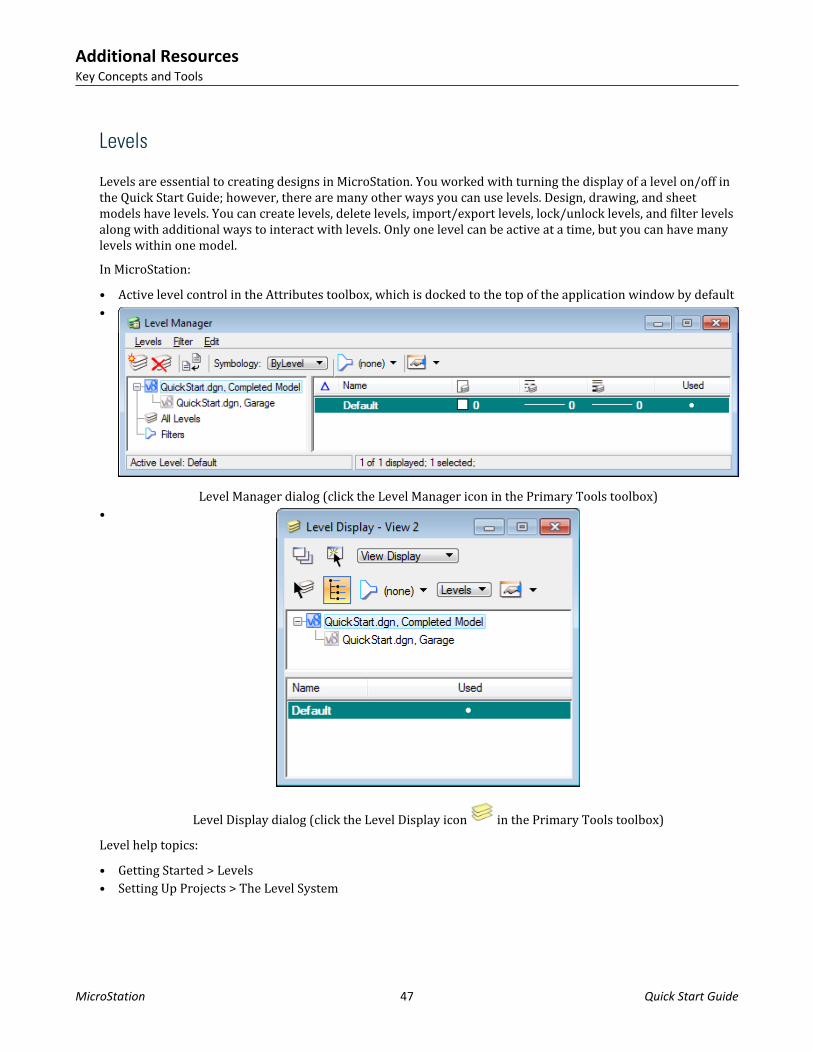
Levels are essential to creating designs in MicroStation. You worked with turning the display of a level on/off inthe Quick Start Guide; however, there are many other ways you can use levels. Design, drawing, and sheetmodels have levels. You can create levels, delete levels, import/export levels, lock/unlock levels, and filter levelsalong with additional ways to interact with levels. Only one level can be active at a time, but you can have manylevels within one model.In MicroStation:• Active level control in the Attributes toolbox, which is docked to the top of the application window by default•
Level Manager dialog (click the Level Manager icon in the Primary Tools toolbox)•
Level Display dialog (click the Level Display icon in the Primary Tools toolbox)Level help topics:• Getting Started > Levels• Setting Up Projects > The Level System
Additional ResourcesKey Concepts and Tools
MicroStation 47 Quick Start Guide
Project Explorer and Link Sets
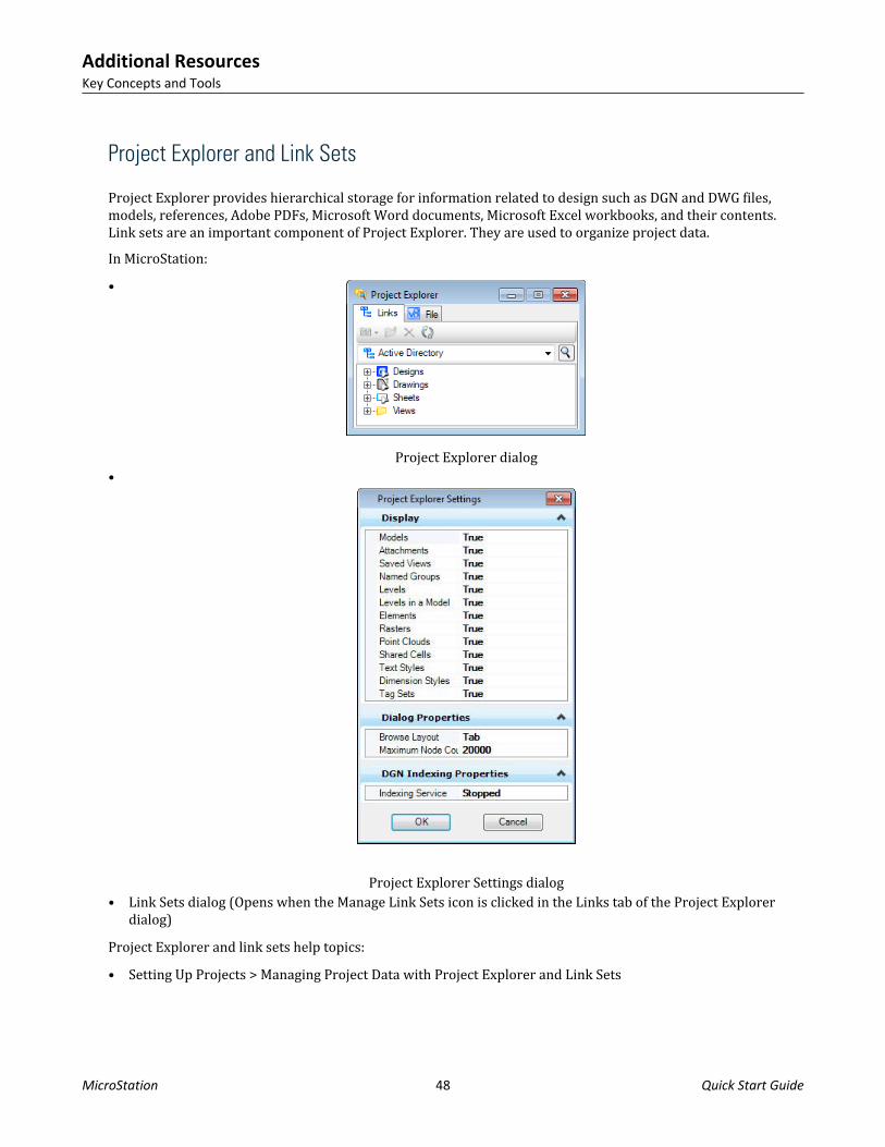
Project Explorer provides hierarchical storage for information related to design such as DGN and DWG files,models, references, Adobe PDFs, Microsoft Word documents, Microsoft Excel workbooks, and their contents.Link sets are an important component of Project Explorer. They are used to organize project data.In MicroStation:•
Project Explorer dialog•
Project Explorer Settings dialog
• Link Sets dialog (Opens when the Manage Link Sets icon is clicked in the Links tab of the Project Explorerdialog)
Project Explorer and link sets help topics:• Setting Up Projects > Managing Project Data with Project Explorer and Link Sets
Additional ResourcesKey Concepts and Tools
MicroStation 48 Quick Start Guide
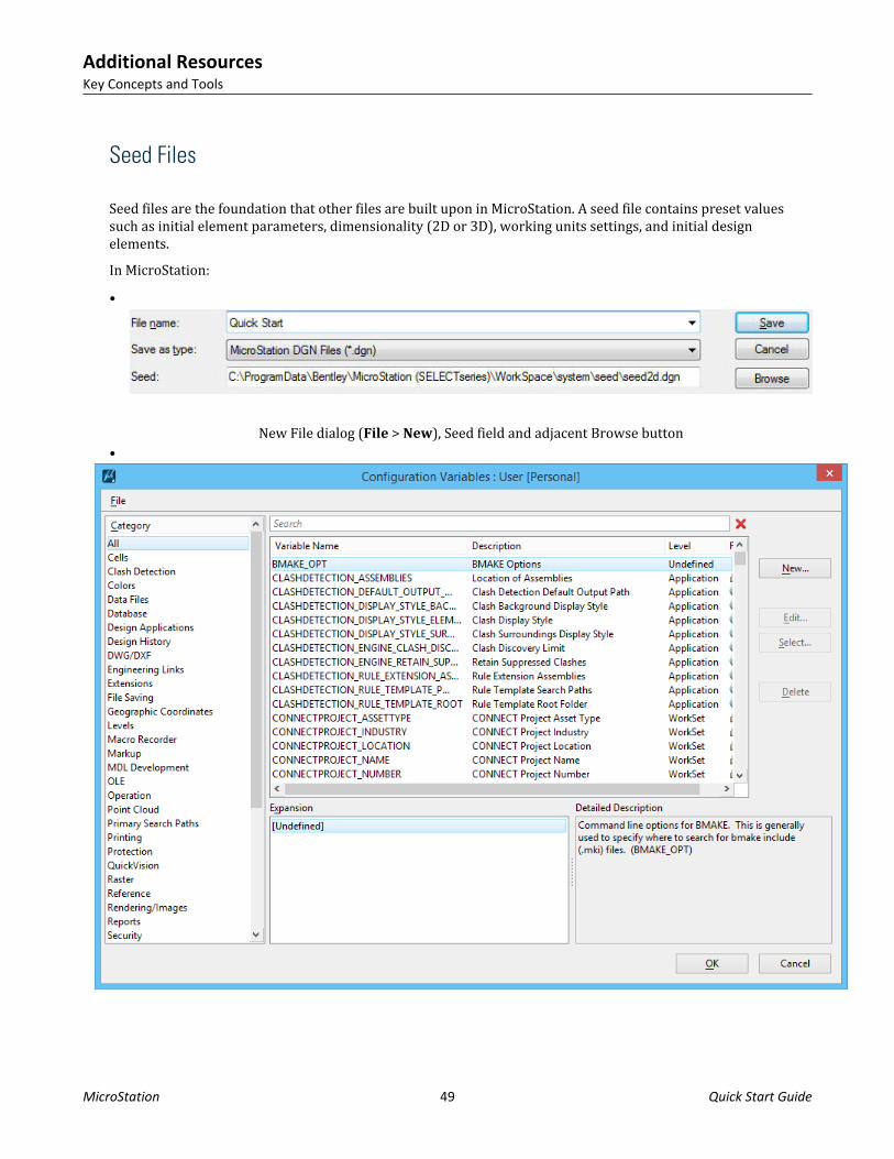
Seed Files
Seed files are the foundation that other files are built upon in MicroStation. A seed file contains preset valuessuch as initial element parameters, dimensionality (2D or 3D), working units settings, and initial designelements.In MicroStation:•
New File dialog (File > New), Seed field and adjacent Browse button
•
Additional ResourcesKey Concepts and Tools
MicroStation 49 Quick Start Guide
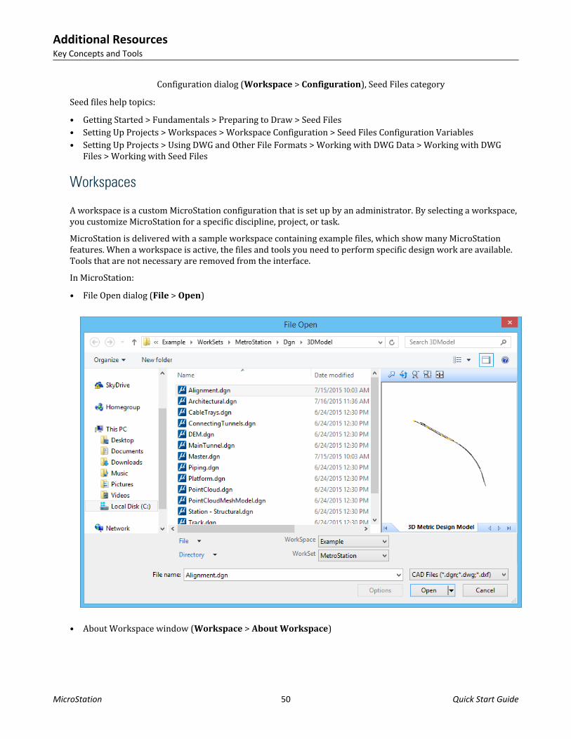
Configuration dialog (Workspace > Configuration), Seed Files categorySeed files help topics:• Getting Started > Fundamentals > Preparing to Draw > Seed Files• Setting Up Projects > Workspaces > Workspace Configuration > Seed Files Configuration Variables• Setting Up Projects > Using DWG and Other File Formats > Working with DWG Data > Working with DWG
Files > Working with Seed Files
Workspaces
A workspace is a custom MicroStation configuration that is set up by an administrator. By selecting a workspace,you customize MicroStation for a specific discipline, project, or task.MicroStation is delivered with a sample workspace containing example files, which show many MicroStationfeatures. When a workspace is active, the files and tools you need to perform specific design work are available.Tools that are not necessary are removed from the interface.In MicroStation:• File Open dialog (File > Open)
• About Workspace window (Workspace > About Workspace)
Additional ResourcesKey Concepts and Tools
MicroStation 50 Quick Start Guide
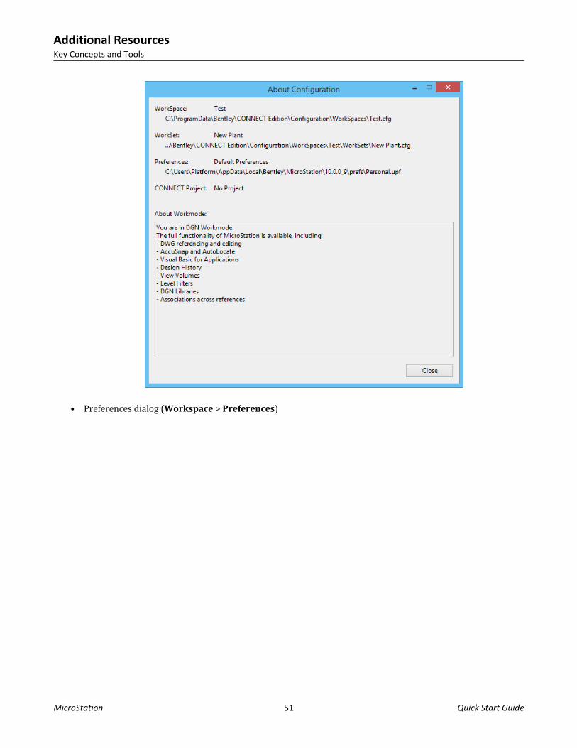
• Preferences dialog (Workspace > Preferences)
Additional ResourcesKey Concepts and Tools
MicroStation 51 Quick Start Guide
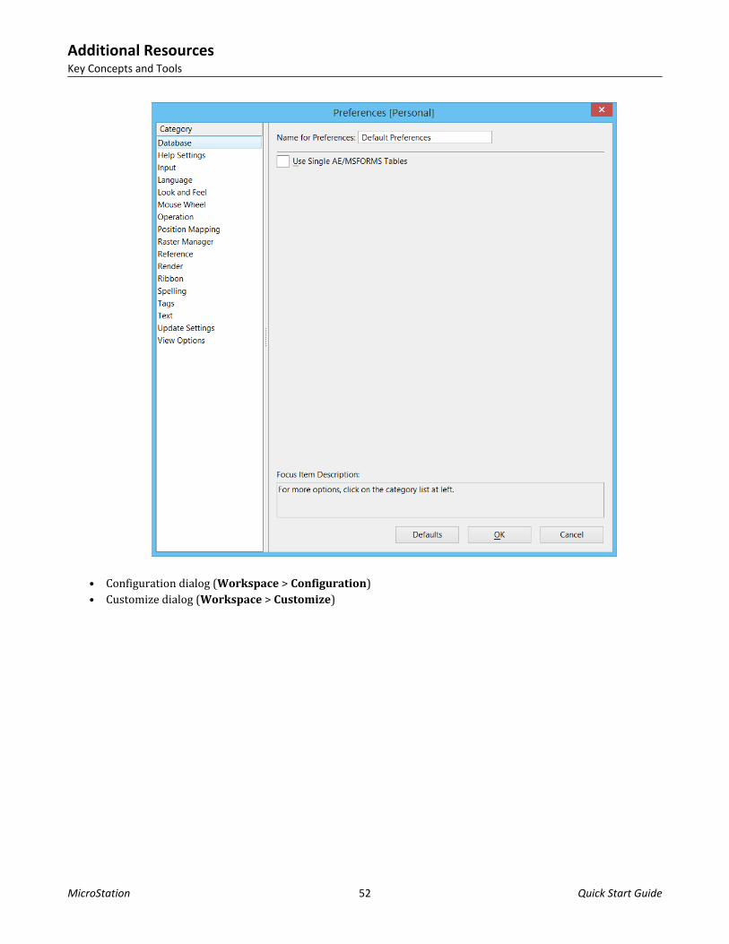
• Configuration dialog (Workspace > Configuration)• Customize dialog (Workspace > Customize)
Additional ResourcesKey Concepts and Tools
MicroStation 52 Quick Start Guide
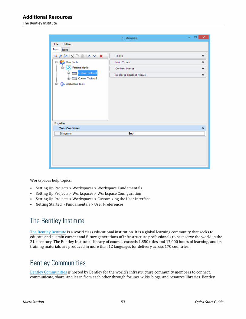
Workspaces help topics:• Setting Up Projects > Workspaces > Workspace Fundamentals• Setting Up Projects > Workspaces > Workspace Configuration• Setting Up Projects > Workspaces > Customizing the User Interface• Getting Started > Fundamentals > User Preferences
The Bentley InstituteThe Bentley Institute is a world class educational institution. It is a global learning community that seeks toeducate and sustain current and future generations of infrastructure professionals to best serve the world in the21st century. The Bentley Institute's library of courses exceeds 1,850 titles and 17,000 hours of learning, and itstraining materials are produced in more than 12 languages for delivery across 170 countries.
Bentley CommunitiesBentley Communities is hosted by Bentley for the world's infrastructure community members to connect,communicate, share, and learn from each other through forums, wikis, blogs, and resource libraries. Bentley
Additional ResourcesThe Bentley Institute
MicroStation 53 Quick Start Guide

Communities is for anyone involved with infrastructure, including current and potential users of Bentley'ssolutions, Bentley colleagues, and others.
Additional ResourcesBentley Communities
MicroStation 54 Quick Start Guide
Top Related