


Languages
Pages
Legal

MicroStation V8i Tips and Tricks and more
September 23, 2013 Page 1 of 10
The following Tips and Tricks include features that are new in the version SELECTSeries 2&3 and some that have been around for a while… enjoy Explorer the File Open dialog. – Let’s take a close look at the File Open dialog.
• Show file details • Add file Properties • Open different file types (Raster, Sketch up etc…)
Switch Interface back – While using the “Use Windows File Open Dialogs” you can toggle back to the old interface by pressing the Shift + ESC keys. It’s a one way trip, not a toggle.
Task Navigation – Note new but very cool.
• Rollup (pushpin) • Turn off totally • Show Main Classic
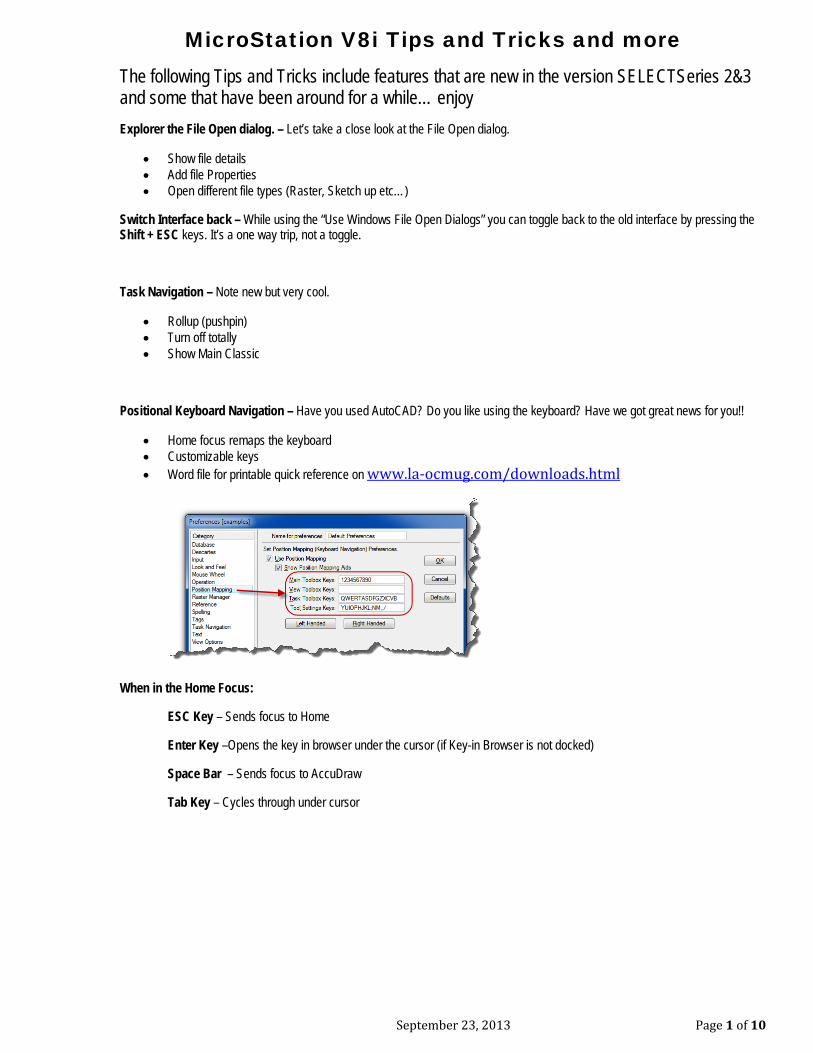
Positional Keyboard Navigation – Have you used AutoCAD? Do you like using the keyboard? Have we got great news for you!!
• Home focus remaps the keyboard • Customizable keys • Word file for printable quick reference on www.la-ocmug.com/downloads.html
When in the Home Focus:
ESC Key – Sends focus to Home
Enter Key –Opens the key in browser under the cursor (if Key-in Browser is not docked)
Space Bar – Sends focus to AccuDraw
Tab Key – Cycles through under cursor
MicroStation V8i Tips and Tricks and more
September 23, 2013 Page 2 of 10
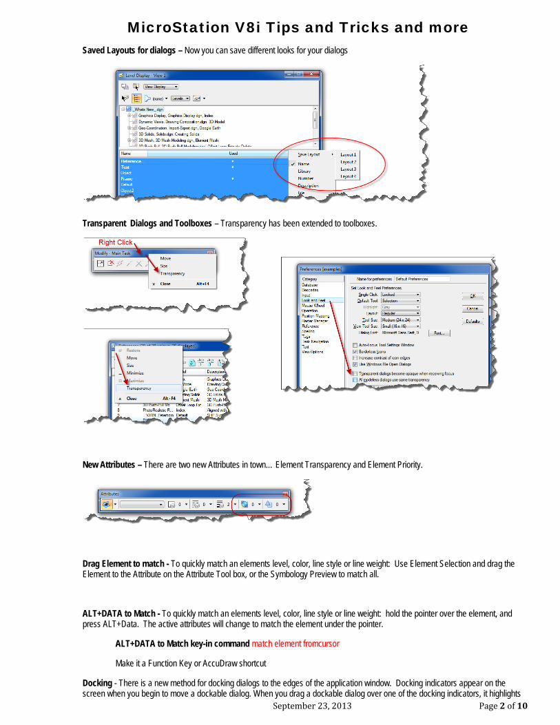
Saved Layouts for dialogs – Now you can save different looks for your dialogs
Transparent Dialogs and Toolboxes – Transparency has been extended to toolboxes.
New Attributes – There are two new Attributes in town… Element Transparency and Element Priority.
Drag Element to match - To quickly match an elements level, color, line style or line weight: Use Element Selection and drag the Element to the Attribute on the Attribute Tool box, or the Symbology Preview to match all.
ALT+DATA to Match - To quickly match an elements level, color, line style or line weight: hold the pointer over the element, and press ALT+Data. The active attributes will change to match the element under the pointer.
ALT+DATA to Match key-in command match element fromcursor
Make it a Function Key or AccuDraw shortcut
Docking - There is a new method for docking dialogs to the edges of the application window. Docking indicators appear on the screen when you begin to move a dockable dialog. When you drag a dockable dialog over one of the docking indicators, it highlights
MicroStation V8i Tips and Tricks and more
September 23, 2013 Page 3 of 10
the available docking region (along the corresponding edge of the application window. Simply release the mouse button, and the dialog becomes docked to the selected edge.
Why is docking cool? Let's look at the Element Information tool.
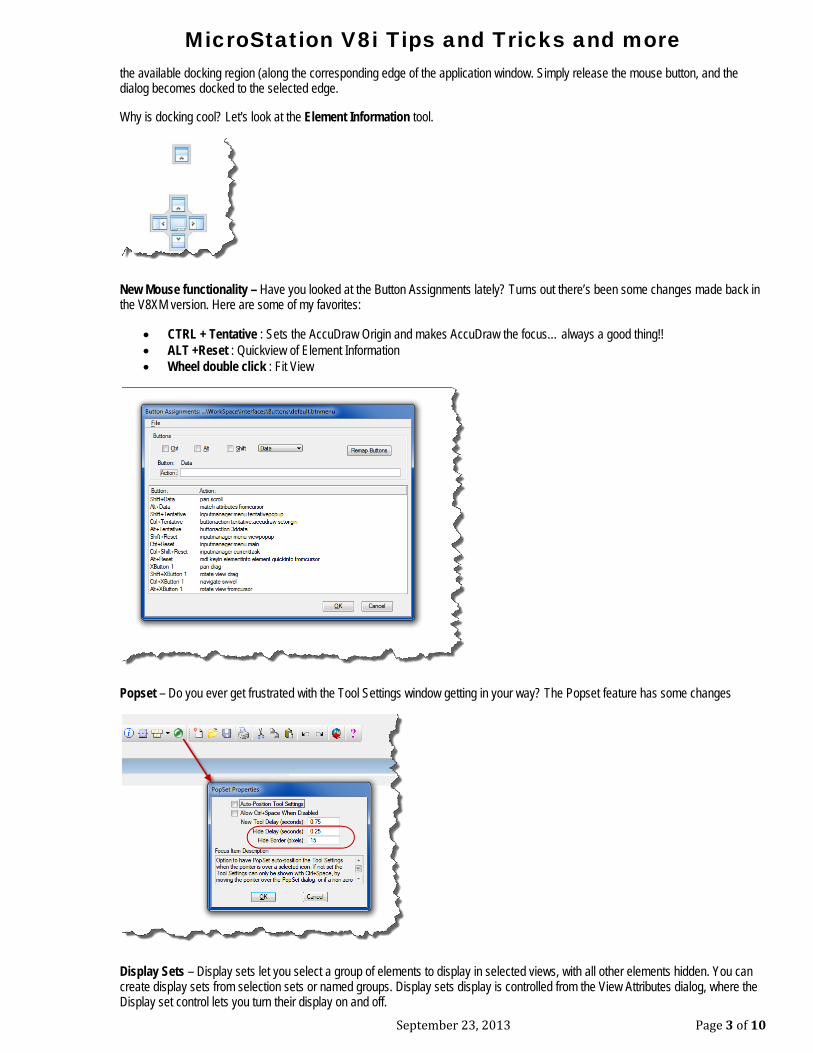
New Mouse functionality – Have you looked at the Button Assignments lately? Turns out there’s been some changes made back in the V8XM version. Here are some of my favorites:
• CTRL + Tentative : Sets the AccuDraw Origin and makes AccuDraw the focus… always a good thing!! • ALT +Reset : Quickview of Element Information • Wheel double click : Fit View
Popset – Do you ever get frustrated with the Tool Settings window getting in your way? The Popset feature has some changes
Display Sets – Display sets let you select a group of elements to display in selected views, with all other elements hidden. You can create display sets from selection sets or named groups. Display sets display is controlled from the View Attributes dialog, where the Display set control lets you turn their display on and off.
MicroStation V8i Tips and Tricks and more
September 23, 2013 Page 4 of 10
With Display sets active, you can use the Named Groups dialog to select a named group and then display only the elements in the group, in the chosen view(s), by clicking the Put Elements into the Display set icon. This lets you quickly switch between different named groups.
Using the view control pop-up menu, you can set selected elements as the display set, or you can clear the display set, so that all elements display. You can also add or remove elements from the display set.
Eye Dropper – In the True Color tab of the Active Color dialog, you can select, hold and drag the eyedropper to anywhere on your monitor to select a color.
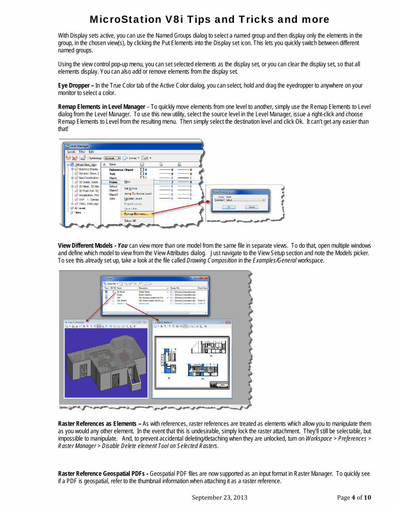
Remap Elements in Level Manager – To quickly move elements from one level to another, simply use the Remap Elements to Level dialog from the Level Manager. To use this new utility, select the source level in the Level Manager, issue a right-click and choose Remap Elements to Level from the resulting menu. Then simply select the destination level and click Ok. It can’t get any easier than that!
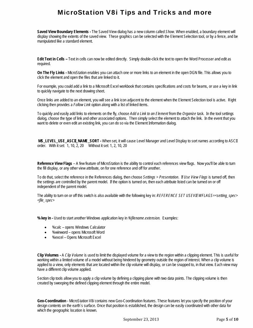
View Different Models - You can view more than one model from the same file in separate views. To do that, open multiple windows and define which model to view from the View Attributes dialog. Just navigate to the View Setup section and note the Models picker. To see this already set up, take a look at the file called Drawing Composition in the Examples/General workspace.
Raster References as Elements – As with references, raster references are treated as elements which allow you to manipulate them as you would any other element. In the event that this is undesirable, simply lock the raster attachment. They’ll still be selectable, but impossible to manipulate. And, to prevent accidental deleting/detaching when they are unlocked, turn on Workspace > Preferences > Raster Manager > Disable Delete element Tool on Selected Rasters.
Raster Reference Geospatial PDFs - Geospatial PDF files are now supported as an input format in Raster Manager. To quickly see if a PDF is geospatial, refer to the thumbnail information when attaching it as a raster reference.
MicroStation V8i Tips and Tricks and more
September 23, 2013 Page 5 of 10
Saved View Boundary Elements - The Saved View dialog has a new column called Show. When enabled, a boundary element will display showing the extents of the saved view. These graphics can be selected with the Element Selection tool, or by a fence, and be manipulated like a standard element.
Edit Text in Cells – Text in cells can now be edited directly. Simply double-click the text to open the Word Processer and edit as required.
On The Fly Links - MicroStation enables you can attach one or more links to an element in the open DGN file. This allows you to click the element and open the files that are linked to it.
For example, you could add a link to a Microsoft Excel workbook that contains specifications and costs for beams, or use a key in link to quickly navigate to the next drawing sheet.
Once links are added to an element, you will see a link icon adjacent to the element when the Element Selection tool is active. Right clicking then provides a Follow Link option along with a list of linked items.
To quickly and easily add links to elements on the fly, choose Add a Link to an Element from the Organize task. In the tool settings dialog, choose the type of link and other associated options. Then simply select the element to attach the link. In the event that you want to delete or even edit an existing link, you can do so via the Element Information dialog.
MS_LEVEL_USE_ASCII_NAME_SORT - When set, it will cause Level Manager and Level Display to sort names according to ASCII order. With it set: 1, 10, 2, 20 Without it set: 1, 2, 10, 20
Reference View Flags – A few feature of MicroStation is the ability to control each references view flags. Now you’ll be able to turn the fill display, or any other view attribute, on for one reference and off for another.
To do that, select the reference in the References dialog, then choose Settings > Presentation. If Use View Flags is turned off, then the settings are controlled by the parent model. If the option is turned on, then each attribute listed can be turned on or off independent of the parent model.
The ability to turn on or off this switch is also available with the following key in: REFERENCE SET USEVIEWFLAGS=<setting_spec> <file_spec>
% key in - Used to start another Windows application key in %filename.extension. Examples:
• %calc – opens Windows Calculator • %winword – opens Microsoft Word • %excel – Opens Microsoft Excel
Clip Volumes - A Clip Volume is used to limit the displayed volume for a view to the region within a clipping element. This is useful for working within a limited volume of a model without being hindered by geometry outside the region of interest. When a clip volume is applied to a view, only elements that are located within the clip volume will display, or can be snapped to, in that view. Each view may have a different clip volume applied.
Section clip tools allow you to apply a clip volume by defining a clipping plane with two data points. The clipping volume is then created by sweeping the defined clipping element through the entire model.
Geo-Coordination - MicroStation V8i contains new Geo-Coordination features. These features let you specify the position of your design contents on the earth´s surface. Once that position is established, the design can be easily coordinated with other data for which the geographic location is known.
MicroStation V8i Tips and Tricks and more
September 23, 2013 Page 6 of 10
Running Coordinates – To enable the display of running coordinates, right-click on the status bar and turn on Running Coordinates from the available options. As you move your cursor, the coordinates of your current position display according to the active Tentative Point Mode. When you left-click, a menu displays six options. When dealing with a Geocoordinate System, such as latitudes and longitudes, choose ACS Position.
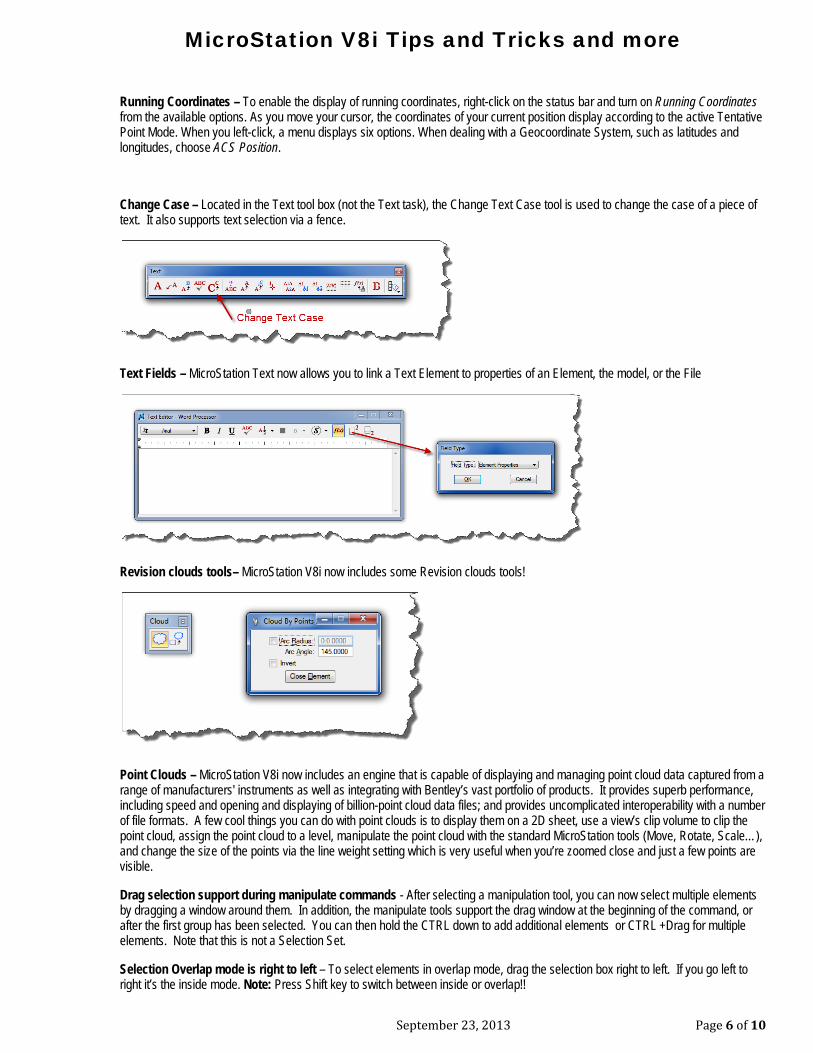
Change Case – Located in the Text tool box (not the Text task), the Change Text Case tool is used to change the case of a piece of text. It also supports text selection via a fence.
Text Fields – MicroStation Text now allows you to link a Text Element to properties of an Element, the model, or the File
Revision clouds tools– MicroStation V8i now includes some Revision clouds tools!
Point Clouds – MicroStation V8i now includes an engine that is capable of displaying and managing point cloud data captured from a range of manufacturers' instruments as well as integrating with Bentley’s vast portfolio of products. It provides superb performance, including speed and opening and displaying of billion-point cloud data files; and provides uncomplicated interoperability with a number of file formats. A few cool things you can do with point clouds is to display them on a 2D sheet, use a view’s clip volume to clip the point cloud, assign the point cloud to a level, manipulate the point cloud with the standard MicroStation tools (Move, Rotate, Scale…), and change the size of the points via the line weight setting which is very useful when you’re zoomed close and just a few points are visible.
Drag selection support during manipulate commands - After selecting a manipulation tool, you can now select multiple elements by dragging a window around them. In addition, the manipulate tools support the drag window at the beginning of the command, or after the first group has been selected. You can then hold the CTRL down to add additional elements or CTRL +Drag for multiple elements. Note that this is not a Selection Set.
Selection Overlap mode is right to left – To select elements in overlap mode, drag the selection box right to left. If you go left to right it’s the inside mode. Note: Press Shift key to switch between inside or overlap!!
MicroStation V8i Tips and Tricks and more
September 23, 2013 Page 7 of 10
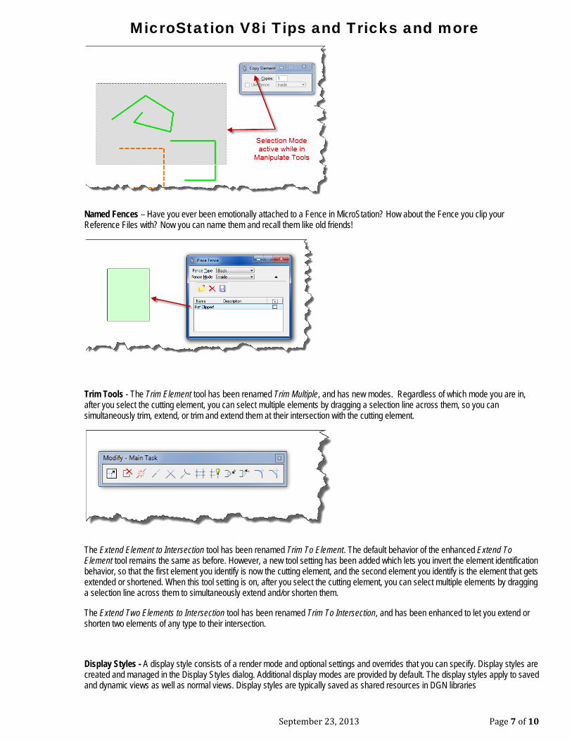
Named Fences – Have you ever been emotionally attached to a Fence in MicroStation? How about the Fence you clip your Reference Files with? Now you can name them and recall them like old friends!
Trim Tools - The Trim Element tool has been renamed Trim Multiple, and has new modes. Regardless of which mode you are in, after you select the cutting element, you can select multiple elements by dragging a selection line across them, so you can simultaneously trim, extend, or trim and extend them at their intersection with the cutting element.
The Extend Element to Intersection tool has been renamed Trim To Element. The default behavior of the enhanced Extend To Element tool remains the same as before. However, a new tool setting has been added which lets you invert the element identification behavior, so that the first element you identify is now the cutting element, and the second element you identify is the element that gets extended or shortened. When this tool setting is on, after you select the cutting element, you can select multiple elements by dragging a selection line across them to simultaneously extend and/or shorten them.
The Extend Two Elements to Intersection tool has been renamed Trim To Intersection, and has been enhanced to let you extend or shorten two elements of any type to their intersection.
Display Styles - A display style consists of a render mode and optional settings and overrides that you can specify. Display styles are created and managed in the Display Styles dialog. Additional display modes are provided by default. The display styles apply to saved and dynamic views as well as normal views. Display styles are typically saved as shared resources in DGN libraries
MicroStation V8i Tips and Tricks and more
September 23, 2013 Page 8 of 10
Change Reference View - In this edition you can change the orientation of the reference attachment by clicking the reference's Orientation column in the References dialog.
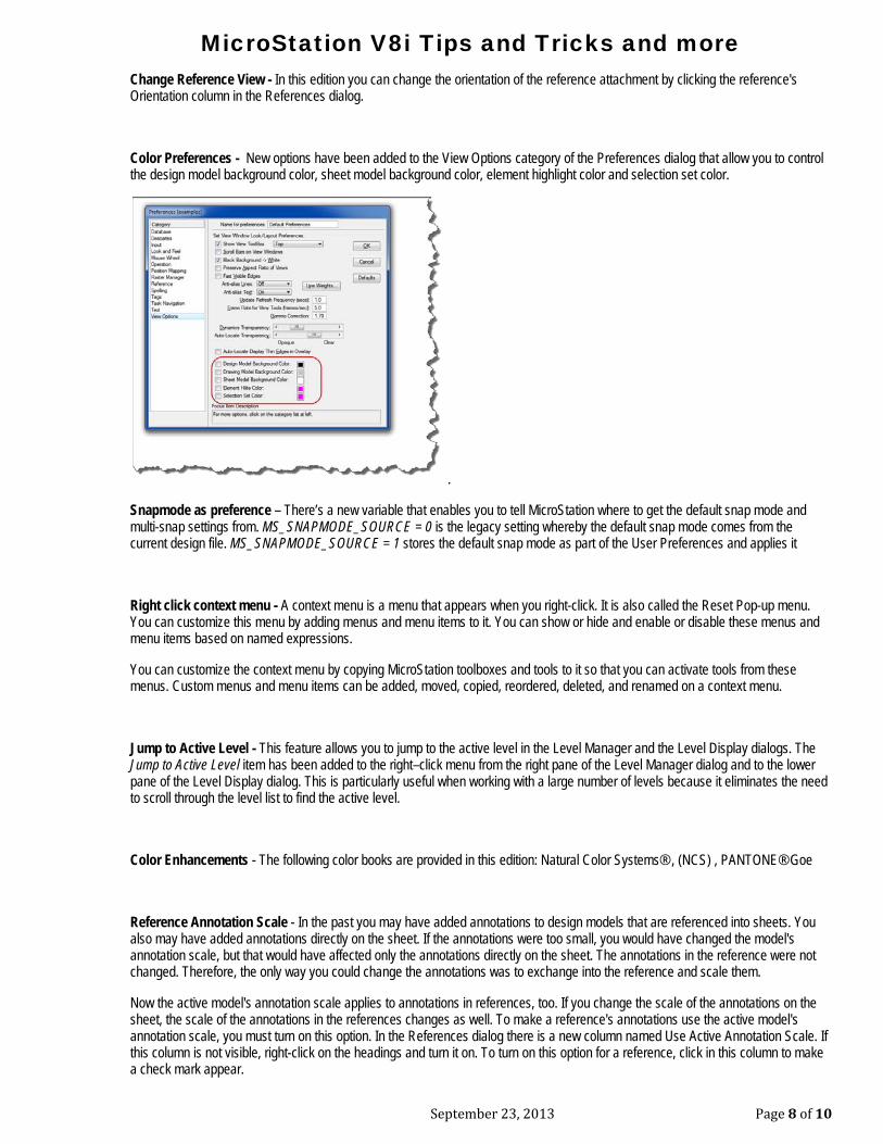
Color Preferences - New options have been added to the View Options category of the Preferences dialog that allow you to control the design model background color, sheet model background color, element highlight color and selection set color.
.
Snapmode as preference – There’s a new variable that enables you to tell MicroStation where to get the default snap mode and multi-snap settings from. MS_SNAPMODE_SOURCE = 0 is the legacy setting whereby the default snap mode comes from the current design file. MS_SNAPMODE_SOURCE = 1 stores the default snap mode as part of the User Preferences and applies it
Right click context menu - A context menu is a menu that appears when you right-click. It is also called the Reset Pop-up menu. You can customize this menu by adding menus and menu items to it. You can show or hide and enable or disable these menus and menu items based on named expressions.
You can customize the context menu by copying MicroStation toolboxes and tools to it so that you can activate tools from these menus. Custom menus and menu items can be added, moved, copied, reordered, deleted, and renamed on a context menu.
Jump to Active Level - This feature allows you to jump to the active level in the Level Manager and the Level Display dialogs. The Jump to Active Level item has been added to the right–click menu from the right pane of the Level Manager dialog and to the lower pane of the Level Display dialog. This is particularly useful when working with a large number of levels because it eliminates the need to scroll through the level list to find the active level.
Color Enhancements - The following color books are provided in this edition: Natural Color Systems® , (NCS) , PANTONE® Goe
Reference Annotation Scale - In the past you may have added annotations to design models that are referenced into sheets. You also may have added annotations directly on the sheet. If the annotations were too small, you would have changed the model's annotation scale, but that would have affected only the annotations directly on the sheet. The annotations in the reference were not changed. Therefore, the only way you could change the annotations was to exchange into the reference and scale them.
Now the active model's annotation scale applies to annotations in references, too. If you change the scale of the annotations on the sheet, the scale of the annotations in the references changes as well. To make a reference's annotations use the active model's annotation scale, you must turn on this option. In the References dialog there is a new column named Use Active Annotation Scale. If this column is not visible, right-click on the headings and turn it on. To turn on this option for a reference, click in this column to make a check mark appear.
MicroStation V8i Tips and Tricks and more
September 23, 2013 Page 9 of 10
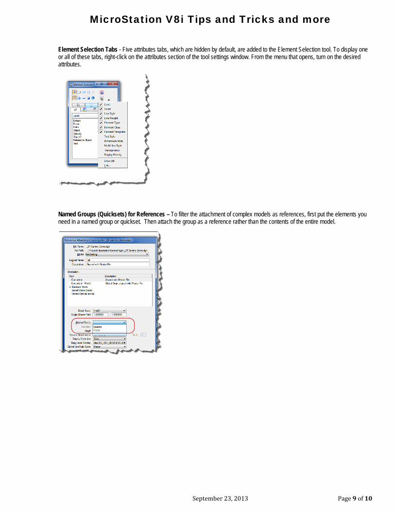
Element Selection Tabs - Five attributes tabs, which are hidden by default, are added to the Element Selection tool. To display one or all of these tabs, right-click on the attributes section of the tool settings window. From the menu that opens, turn on the desired attributes.
Named Groups (Quicksets) for References – To filter the attachment of complex models as references, first put the elements you need in a named group or quickset. Then attach the group as a reference rather than the contents of the entire model.
MicroStation V8i Tips and Tricks and more
September 23, 2013 Page 10 of 10
Reference Activation - A new capability lets you edit a reference in-place. That is, you can edit a reference from within the active model. To do this you first must activate the reference. When you activate a reference, you must open it for write access thus blocking any other users from modifying that file. As you activate references, you acquire their locks and hold them until you either explicitly release them or exit your session. The reason that deactivate doesn't automatically release the lock, is that once the lock is relinquished it is not possible to undo changes. So, if you are actively working on a set of 3 files jumping from one to another via activation, it makes sense to hold the locks until you decide you're ready to release them.
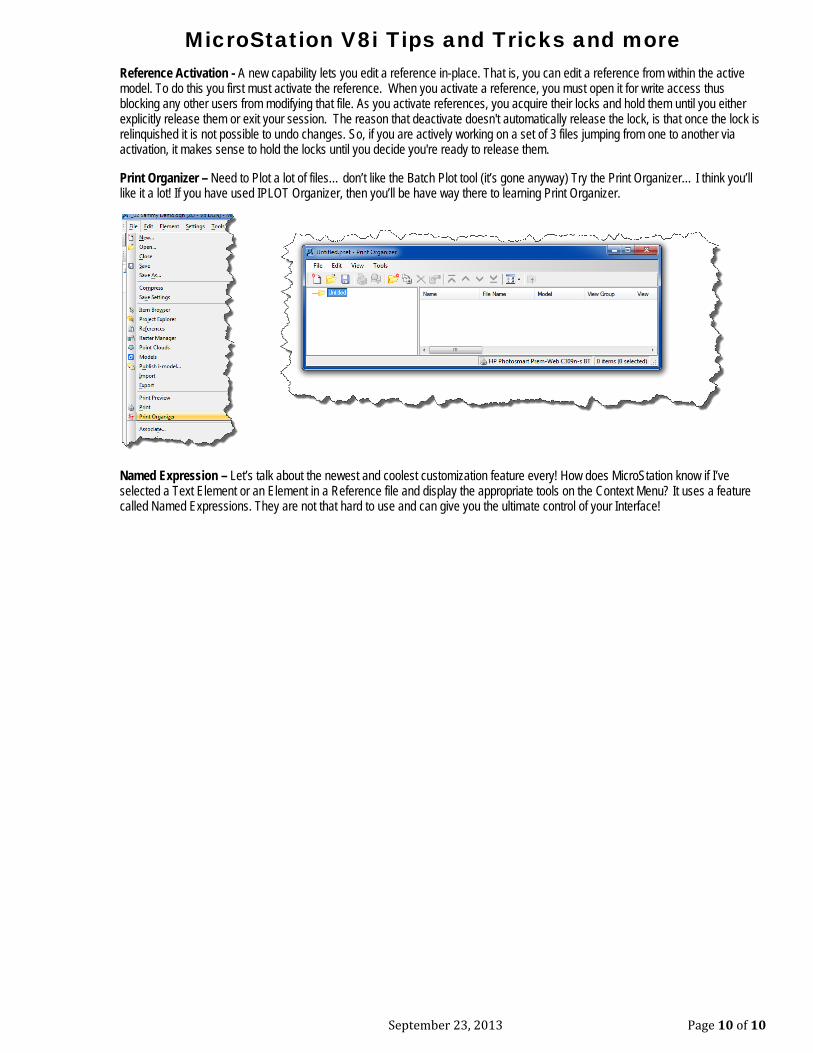
Print Organizer – Need to Plot a lot of files… don’t like the Batch Plot tool (it’s gone anyway) Try the Print Organizer… I think you’ll like it a lot! If you have used IPLOT Organizer, then you’ll be have way there to learning Print Organizer.
Named Expression – Let’s talk about the newest and coolest customization feature every! How does MicroStation know if I’ve selected a Text Element or an Element in a Reference file and display the appropriate tools on the Context Menu? It uses a feature called Named Expressions. They are not that hard to use and can give you the ultimate control of your Interface!
Top Related