


Languages
Pages
Legal


(A2LA Cert. No. 1312.01) 06/12/2017 Page 1 of 22
SCOPE OF ACCREDITATION TO ISO/IEC 17025:2005
& ANSI/NCSL Z540-1-1994
MICRO LABORATORIES INC. 7158 Industrial Park Mentor, OH 44060
Keith Kokal Phone: 440 918 0001
CALIBRATION Valid To: July 31, 2019 Certificate Number: 1312.01 In recognition of the successful completion of the A2LA evaluation process, accreditation is granted to this laboratory to perform the following calibrations1: I. Dimensional
Parameter/Equipment
Range CMC2, 4 ()
Comments
Bore Micrometers3
(0.5 to 12) in 100 µin Ring gages
Calipers3
(0.05 to 60) in (620 + 3.5L) in Gage blocks/height
gage
Chamfer Check Gages3
Up to 4 in 82 in Chamfer check master
Chamfer Set Master
Up to 12 in 29 in Optical comparator and
angle blocks, amp and indicator, splate
Concentricity Gage
Up to 2 in 27 µin Mu checker/pin gage
Dial Bore Gages3
(0.05 to 12) in
67 in Ring gages
Digital Bore Gages3
(0.05 to 12) in 67 in Ring gages
Electronic Indicators and Amplifiers3
Up to 2 in
8 in Optical height gage,
surface plate, gage blocks

(A2LA Cert. No. 1312.01) 06/12/2017 Page 2 of 22
Parameter/Equipment
Range CMC2, 4 ()
Comments
Feeler Gages
Up to 1 in 20 in SupermicrometerTM,
Gage Balls/CMM Sphere
(0.001 through 4) in
17 in SupermicrometerTM
Gage Blocks
(0.01 to 4.0) in (5 to 20) in Up to 20 in
(3.5 + 2L) in (24 + 1.1L) in (14 + 4.5L) µin
Mechanical comparison Mahr ULM
Gear Wires –
Pitch
(1 to 200) pitch
22 in
SupermicrometerTM
Height Gages3
(1 to 60) in (70 + 4L) in Height master
Indicator Calibrators
Up to 1 in (21 + 2L) in Gage blocks/ Mu
checker
Indicators3
(0.00002 to 2) in (30 + 6.5L) in Indicator calibrator
Indicators / LVDT’s3
Up to 2 in
8 in Optical height gage,
surface plate, gage blocks
Laser Micrometer Verification3
Up to 6 in
23 in Master pin standards
Levels
-45° through +45° 150 in Surface plate, gage blocks
Luer Tapered Rings –
Length/Step Small Diameter Large Diameter Taper
Up to 1500 mm Up to 100 mm Up to 100 mm
(14 + 4.5L) µin (80 + 2L) µin (80 + 2L) µin 5 µin
ISO 594/1 3a &3b Height gage IAC MasterScanner IAC MasterScanner IAC MasterScanner

(A2LA Cert. No. 1312.01) 06/12/2017 Page 3 of 22
Parameter/Equipment
Range CMC2, 4 ()
Comments
Luer Tapered Plugs –
Length/Step Small Diameter Large Diameter Taper
Up to 1500 mm Up to 100 mm Up to 100 mm
(14 + 4.5L) µin (80 + 2L) µin (80 + 2L) µin 5 µin
ISO 594/1 3c Optical height gage IAC MasterScanner IAC MasterScanner IAC MasterScanner
Luer Ref Conical Fitting –
Length/Step Diameter Flank Angle
Up to 1500 mm Up to 100 mm Up to 30°
(14 + 4.5L) µin (17 + 3.3L) µin 0°6”0’
ISO 594-2 Figures 5 & 6 Mahr ULM Mahr ULM IAC MasterScanner
Luer Ref Conical Fitting –
Interior Diameter Interior Diameter Angles
Up to 100 mm Up to 100 mm Up to 30°
(40 + 5L) µin (40 + 5L) µin 0°6”0’
ISO 594-2 Figure 7 Mahr ULM Mahr ULM IAC MasterScanner
Luer Ref Conical Fitting –
Interior Diameter Interior Diameter
Angles
Up to 100 mm Up to 100 mm Up to 30°
(40 + 5L) µin (40 + 5L) µin 0°6”0’
ISO 594-2 Figure 8 Mahr ULM Mahr ULM IAC MasterScanner
Luer Ref Steel Male Conical Fitting –
Diameter Length
Up to 100 mm Up to 1500 mm
(80 + 2L) µin (14 + 4.5L) µin
ISO 594-2 Figure 5 IAC MasterScanner Optical height gage
(A2LA Cert. No. 1312.01) 06/12/2017 Page 4 of 22
Parameter/Equipment
Range CMC2, 4 ()
Comments
Luer Ref Steel Female Conical Fitting –
Diameter Length
Up to 100 mm Up to 1500 mm
(80 + 2L) µin (14 + 4.5L) µin
ISO 594-1 Figure 4 IAC MasterScanner Optical height gage
MasterScanner Master Gage (Gauge)
DIN Ring, ID Wires
13 µin 9.4 µin
Mahr ULM
MasterScanner Reference Plane gage (gauge)
(0.0250 to 0.2500) in Wires Height
9.4 µin 7.5 µin
Mahr ULM, Mu checker, surface plate
Micrometers3
(0.05 to 48) in
(94 + 3.5L) in Gage blocks/optical flats
Micrometer Setting Masters and Caliper Setting Masters
(1 to 60) in (40 + 4L) in Height gage, Mu checker,
and surface plate
Micrometer Setting Standards, Length Standards
(1 to 60) in (15 + 4L) in Optical height gage and
Mu checker
Optical Comparators and Optical Measuring Machines3
Magnification-
Up to 8 in (>8 to 16) in (>16 to 36) in
Linear Axis Angularity
5x, 10x, 20x, 30x, 31.25x, 50x, 62.5x X & Y Axis 0° to 360°
0.011 % of magnification 1000 in 1’ 12”
Magnification standards optical linear standards angle blocks Glass scale, magnification checker Glass scale Angle blocks
Optical Flats
Up to 6 in 1.2 in Optical interferometer
Parallels
Up to 36 in (66 + 32L) in Surface plate and indicator

(A2LA Cert. No. 1312.01) 06/12/2017 Page 5 of 22
Parameter/Equipment
Range CMC2, 4 ()
Comments
Pin Gages (OD)
(0.01 to 4) in
Up to 20 in
22 in (15 + 3.2L) µin
SupermicrometerTM
Mahr ULM
Plug Gages (OD) –
Taper Diameter
(0.001 to 4) in (0.001 to 20) in (0.039 to 3.7) in (0.039 to 3.7) in
22 in (15 + 3.2L) µin 5 µin (80 + 2L) µin
SupermicrometerTM
Mahr ULM IAC Masterscanner IAC Masterscanner
Protractors /Digital
0° through 360°
0° 6” 29’
Sine bar / surface plate /gage blocks
Radius Gages
Up to 6 in
2000 in
Optical comparator
Railroad Track Gage/ Geismar Bar –
Linearity Elevation
Up to 62 in Up to 62 in
0.030 in 0.037 in
Rail Gage
Ring Gages (ID) –
Taper Diameter
(0.06 to 12) in (0.118 to 4) in (0.118 to 4) in
(17 + 3.3L) µin 5 µin (40 + 5L) µin
Mahr ULM IAC Masterscanner IAC Masterscanner
Screw Thread Micrometers3
Up to 6 in
150 in Master screw thread
standards
Screw Thread Micrometer Standards
Up to 6 in
200 in Nikon optical comparator
and Supermicrometer

(A2LA Cert. No. 1312.01) 06/12/2017 Page 6 of 22
Parameter/Equipment
Range CMC2, 4 ()
Comments
Sine Bars/Sine Plates Angle Parallelism
Up to 10”
Up to 10 in
0° 5” 40 in
Surface plate electronic indicator/amp, optical height gage
Snap Gages3
(0.125 to 20) in
(120 + 4.8L) in Gage blocks
Square Masters
Up to 0.008 in
50 in Granite square, surface plate,
indicator
Squareness
Up to 0.008 in 45 in Square master
Spline Gages
Up to 12 in 40 in ULM with wires or balls
Stage Micrometer
Up to 4 in Up to 48 in
80 µin 600 µin
Mahr ULM with scope. custom optical vision linear system
Steel Rules/Tapes
Up to 100 ft 600 in Optical vision measuring
system
SupermicrometerTM
Up to 48 in 16 in Gage blocks and force gage
SupermicrometersTM, 3
Up to 48 in 16 µin
Gage blocks and force gage
Surface Finish Testers3
2 to 500 µin
4 in Roughness standards
Surface Roughness Standards
(2 to 500) in
3.5 in
Roughness analyzer
(A2LA Cert. No. 1312.01) 06/12/2017 Page 7 of 22
Parameter/Equipment
Range CMC2, 4 ()
Comments
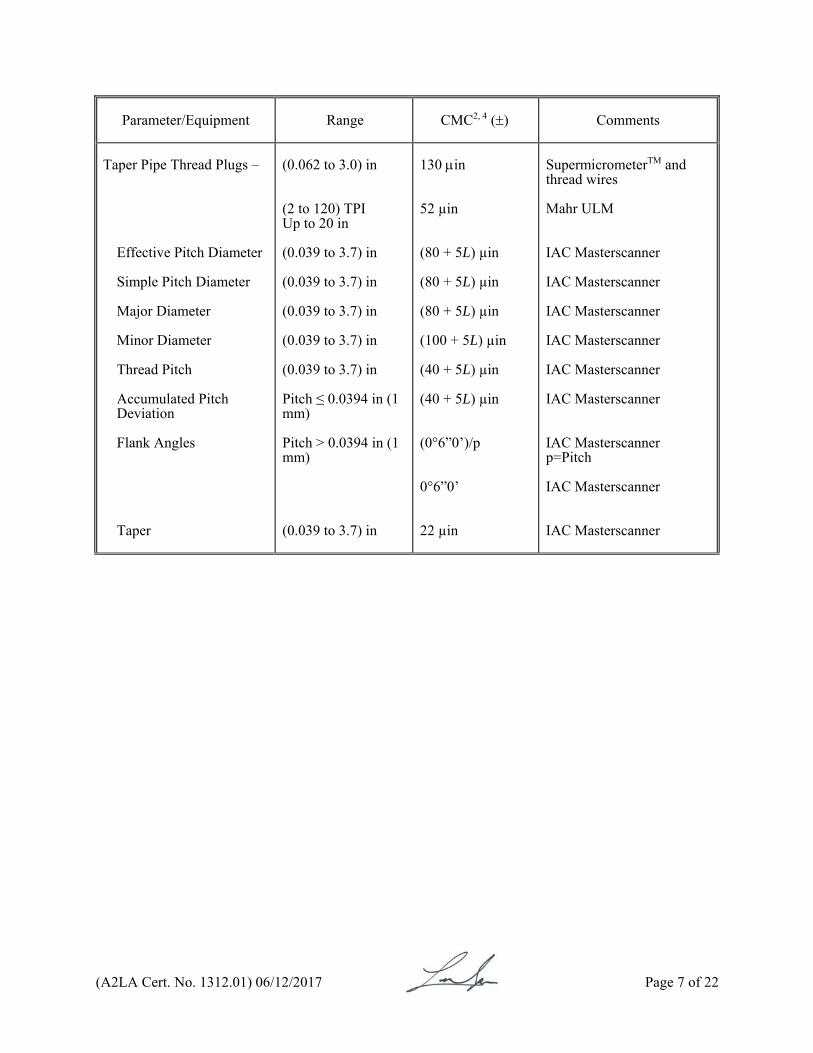
Taper Pipe Thread Plugs –
Effective Pitch Diameter Simple Pitch Diameter Major Diameter Minor Diameter Thread Pitch Accumulated Pitch Deviation Flank Angles Taper
(0.062 to 3.0) in (2 to 120) TPI Up to 20 in (0.039 to 3.7) in
(0.039 to 3.7) in (0.039 to 3.7) in (0.039 to 3.7) in (0.039 to 3.7) in Pitch ≤ 0.0394 in (1 mm) Pitch > 0.0394 in (1 mm) (0.039 to 3.7) in
130 in 52 µin (80 + 5L) µin (80 + 5L) µin (80 + 5L) µin (100 + 5L) µin (40 + 5L) µin (40 + 5L) µin (0°6”0’)/p 0°6”0’ 22 µin
SupermicrometerTM and thread wires Mahr ULM IAC Masterscanner IAC Masterscanner IAC Masterscanner IAC Masterscanner IAC Masterscanner IAC Masterscanner IAC Masterscanner p=Pitch IAC Masterscanner IAC Masterscanner

(A2LA Cert. No. 1312.01) 06/12/2017 Page 8 of 22
Parameter/Equipment
Range CMC2, 4 ()
Comments
Taper Pipe Thread Rings –
Effective Pitch Diameter Simple Pitch Diameter Major Diameter Minor Diameter Thread Pitch Accumulated Pitch Deviation Flank Angles Taper
(0.062 to 3.0) in (2 to 120) TPI Up to 12 in (0.118 to 4) in
(0.118 to 4) in (0.118 to 4) in (0.118 to 4) in (0.118 to 4) in (0.118 to 4) in Pitch ≤ 0.0394 in (1 mm) Pitch > 0.0394 in (1 mm) (0.118 to 4) in
170 in 52 µin (80 + 5L) µin (80 + 5L) µin (80 + 5L) µin (100 + 5L) µin (40 + 5L) µin (40 + 5L) µin (0°6”0’)/p 0°6”0’ 22 µin
Master plugs Mahr ULM IAC Masterscanner IAC Masterscanner IAC Masterscanner IAC Masterscanner IAC Masterscanner IAC Masterscanner IAC Masterscanner p=Pitch IAC Masterscanner IAC Masterscanner
Thickness Gages
Up to 1 in 20 in SupermicrometerTM
Thread Plug Gages –
Effective Pitch Diameter Simple Pitch Diameter Major Diameter Minor Diameter Thread Pitch Accumulated Pitch Deviation
(2 to 120) TPI Up to 36 in (2 to 120) TPI Up to 20 in (0.039 to 3.7) in (0.039 to 3.7) in (0.039 to 3.7) in (0.039 to 3.7) in (0.039 to 3.7) in (0.039 to 3.7) in
85 in 74 µin (80 + 5L) µin (80 + 5L) µin (80 + 5L) µin (100 + 5L) µin (40 + 5L) µin (40 + 5L) µin
SupermicrometerTM and thread wires Mahr ULM IAC Masterscanner IAC Masterscanner IAC Masterscanner IAC Masterscanner IAC Masterscanner IAC Masterscanner
(A2LA Cert. No. 1312.01) 06/12/2017 Page 9 of 22
Parameter/Equipment
Range CMC2, 4 ()
Comments
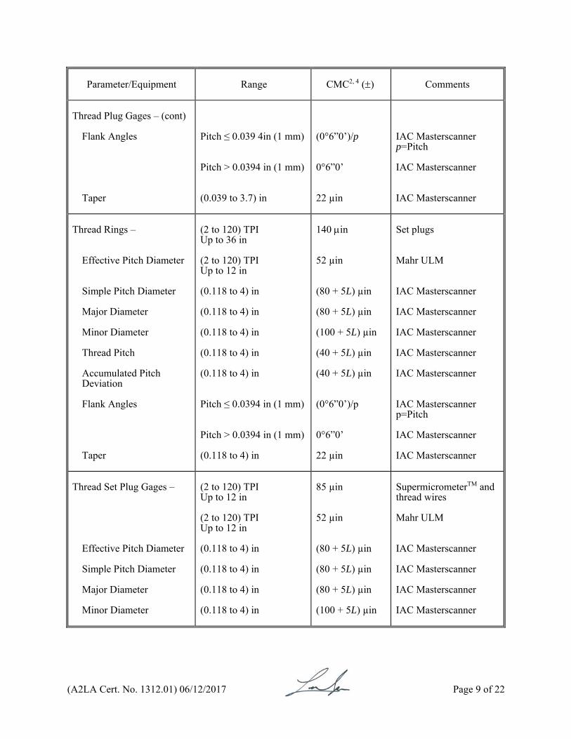
Thread Plug Gages – (cont)
Flank Angles Taper
Pitch ≤ 0.039 4in (1 mm) Pitch > 0.0394 in (1 mm) (0.039 to 3.7) in
(0°6”0’)/p 0°6”0’ 22 µin
IAC Masterscanner p=Pitch IAC Masterscanner IAC Masterscanner
Thread Rings –
Effective Pitch Diameter Simple Pitch Diameter Major Diameter Minor Diameter Thread Pitch Accumulated Pitch Deviation Flank Angles Taper
(2 to 120) TPI Up to 36 in (2 to 120) TPI Up to 12 in (0.118 to 4) in (0.118 to 4) in (0.118 to 4) in (0.118 to 4) in (0.118 to 4) in Pitch ≤ 0.0394 in (1 mm) Pitch > 0.0394 in (1 mm) (0.118 to 4) in
140 in 52 µin (80 + 5L) µin (80 + 5L) µin (100 + 5L) µin (40 + 5L) µin (40 + 5L) µin (0°6”0’)/p 0°6”0’ 22 µin
Set plugs Mahr ULM IAC Masterscanner IAC Masterscanner IAC Masterscanner IAC Masterscanner IAC Masterscanner IAC Masterscanner p=Pitch IAC Masterscanner IAC Masterscanner
Thread Set Plug Gages –
Effective Pitch Diameter Simple Pitch Diameter Major Diameter Minor Diameter
(2 to 120) TPI Up to 12 in (2 to 120) TPI Up to 12 in (0.118 to 4) in
(0.118 to 4) in (0.118 to 4) in (0.118 to 4) in
85 µin 52 µin (80 + 5L) µin (80 + 5L) µin (80 + 5L) µin (100 + 5L) µin
SupermicrometerTM and thread wires Mahr ULM IAC Masterscanner IAC Masterscanner IAC Masterscanner IAC Masterscanner
(A2LA Cert. No. 1312.01) 06/12/2017 Page 10 of 22
Parameter/Equipment
Range CMC2, 4 ()
Comments
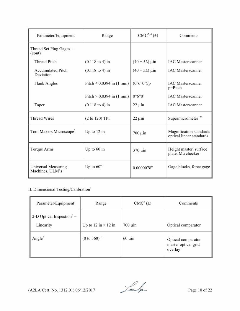
Thread Set Plug Gages – (cont)
Thread Pitch Accumulated Pitch Deviation Flank Angles Taper
(0.118 to 4) in (0.118 to 4) in Pitch ≤ 0.0394 in (1 mm) Pitch > 0.0394 in (1 mm) (0.118 to 4) in
(40 + 5L) µin (40 + 5L) µin (0°6”0’)/p 0°6”0’ 22 µin
IAC Masterscanner IAC Masterscanner IAC Masterscanner p=Pitch IAC Masterscanner IAC Masterscanner
Thread Wires
(2 to 120) TPI 22 in SupermicrometerTM
Tool Makers Microscope3
Up to 12 in
700 in Magnification standards
optical linear standards
Torque Arms
Up to 60 in
370 µin Height master, surface
plate, Mu checker
Universal Measuring Machines, ULM’s
Up to 60”
0.0000078” Gage blocks, force gage
II. Dimensional Testing/Calibration1
Parameter/Equipment
Range CMC2 ()
Comments
2-D Optical Inspection5 –
Linearity
Up to 12 in × 12 in
700 µin
Optical comparator
Angle5
(0 to 360) ° 60 µin
Optical comparator master optical grid overlay
(A2LA Cert. No. 1312.01) 06/12/2017 Page 11 of 22
Parameter/Equipment
Range CMC2, 4 ()
Comments
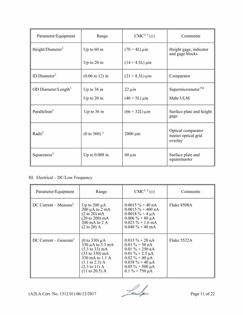
Height/Diameter5
Up to 60 in Up to 20 in
(70 + 4L) in (14 + 4.5L) µin
Height gage, indicator and gage blocks
ID Diameter5
(0.06 to 12) in
(21 + 8.3L) in Comparator
OD Diameter/Length5
Up to 36 in Up to 20 in
22 in (40 + 5L) µin
SupermicrometerTM
Mahr ULM
Parallelism5
Up to 36 in (66 + 32L) in Surface plate and height
gage
Radii5
(0 to 360) °
2000 µin
Optical comparator master optical grid overlay
Squareness5
Up to 0.008 in 60 in Surface plate and
squaremaster
III. Electrical – DC/Low Frequency
Parameter/Equipment
Range CMC2, 6 ()
Comments
DC Current – Measure3
Up to 200 µA 200 µA to 2 mA (2 to 20) mA (20 to 200) mA 200 mA to 2 A (2 to 20) A
0.0015 % + 40 nA 0.0015 % + 400 nA 0.0018 % + 4 µA 0.006 % + 80 µA 0.023 % + 1.6 mA 0.048 % + 40 mA
Fluke 8508A
DC Current – Generate3
(0 to 330) µA 330 µA to 3.3 mA (3.3 to 33) mA (33 to 330) mA 330 mA to 1.1 A (1.1 to 2.3) A (2.3 to 11) A (11 to 20.5) A
0.015 % + 20 nA 0.01 % + 50 nA 0.01 % + 250 nA 0.01 % + 2.5 μA 0.02 % + 40 μA 0.038 % + 40 μA 0.05 % + 500 μA 0.1 % + 750 μA
Fluke 5522A
(A2LA Cert. No. 1312.01) 06/12/2017 Page 12 of 22
Parameter/Equipment
Range CMC2, 6 ()
Comments
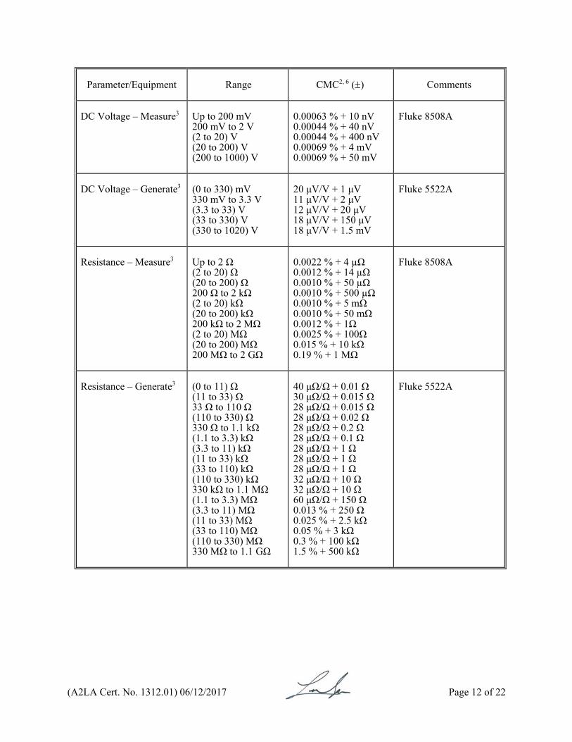
DC Voltage – Measure3
Up to 200 mV 200 mV to 2 V (2 to 20) V (20 to 200) V (200 to 1000) V
0.00063 % + 10 nV 0.00044 % + 40 nV 0.00044 % + 400 nV 0.00069 % + 4 mV 0.00069 % + 50 mV
Fluke 8508A
DC Voltage – Generate3
(0 to 330) mV 330 mV to 3.3 V (3.3 to 33) V (33 to 330) V (330 to 1020) V
20 μV/V + 1 μV 11 μV/V + 2 μV 12 μV/V + 20 μV 18 μV/V + 150 μV 18 μV/V + 1.5 mV
Fluke 5522A
Resistance – Measure3
Up to 2 Ω (2 to 20) Ω (20 to 200) Ω 200 Ω to 2 kΩ (2 to 20) kΩ (20 to 200) kΩ 200 kΩ to 2 MΩ (2 to 20) MΩ (20 to 200) MΩ 200 MΩ to 2 GΩ
0.0022 % + 4 µΩ 0.0012 % + 14 µΩ 0.0010 % + 50 µΩ 0.0010 % + 500 µΩ 0.0010 % + 5 mΩ 0.0010 % + 50 mΩ 0.0012 % + 1Ω 0.0025 % + 100Ω 0.015 % + 10 kΩ 0.19 % + 1 MΩ
Fluke 8508A
Resistance – Generate3
(0 to 11) Ω (11 to 33) Ω 33 Ω to 110 Ω (110 to 330) Ω 330 Ω to 1.1 kΩ (1.1 to 3.3) kΩ (3.3 to 11) kΩ (11 to 33) kΩ (33 to 110) kΩ (110 to 330) kΩ 330 kΩ to 1.1 MΩ (1.1 to 3.3) MΩ (3.3 to 11) MΩ (11 to 33) MΩ (33 to 110) MΩ (110 to 330) MΩ 330 MΩ to 1.1 GΩ
40 μΩ/Ω + 0.01 Ω 30 μΩ/Ω + 0.015 Ω 28 μΩ/Ω + 0.015 Ω 28 μΩ/Ω + 0.02 Ω 28 μΩ/Ω + 0.2 Ω 28 μΩ/Ω + 0.1 Ω 28 μΩ/Ω + 1 Ω 28 μΩ/Ω + 1 Ω 28 μΩ/Ω + 1 Ω 32 μΩ/Ω + 10 Ω 32 μΩ/Ω + 10 Ω 60 μΩ/Ω + 150 Ω 0.013 % + 250 Ω 0.025 % + 2.5 kΩ 0.05 % + 3 kΩ 0.3 % + 100 kΩ 1.5 % + 500 kΩ
Fluke 5522A

(A2LA Cert. No. 1312.01) 06/12/2017 Page 13 of 22
Parameter/Equipment
Range CMC2, 6 ()
Comments
AC Voltage – Measure3 Up to 200 mV 200 mV to 2V (2 to 20) V (20 to 200) V (200 to 1000) V
(1 to 10) Hz (10 to 40) Hz (40 to 100) Hz 100 Hz to 2 kHz (2 to 10) kHz (10 to 30) kHz (30 to 100) kHz (1 to 10) Hz (10 to 40) Hz (40 to 100) Hz 100 Hz to 2 kHz (2 to 10) kHz (10 to 30) kHz (30 to 100) kHz (100 to 300) kHz 300 kHz to 1 MHz (1 to 10) Hz (10 to 40) Hz (40 to 100) Hz 100 Hz to 2 kHz (2 to 10) kHz (10 to 30) kHz (30 to 100) kHz (100 to 300) kHz 300 kHz to 1 MHz (1 to 10) Hz (10 to 40) Hz (40 to 100) Hz 100 Hz to 2 kHz (2 to 10) kHz (10 to 30) kHz (30 to 100) kHz (100 to 300) kHz 300 kHz to 1 MHz (1 to 10) Hz (10 to 40) Hz 40 Hz to 10 kHz (10 to 30) kHz (30 to 100) kHz
0.021 % + 14 µV 0.018 % + 4 µV 0.015 % + 4 µV 0.014 % + 2 µV 0.017 % + 4 µV 0.043 % + 8 µV 0.096 % + 20 µV 0.019 % + 120 µV 0.015 % + 20 µV 0.012 % + 20 µV 0.010 % + 20 µV 0.014 % + 20 µV 0.028 % + 40 µV 0.072 % + 200 µV 0.38 % + 200 µV 1.3 % + 2 mV 0.019 % + 1.2 mV 0.015 % + 200 µV 0.012 % + 200 µV 0.010 % + 200 µV 0.014 % + 200 µV 0.028 % + 400 µV 0.072 % + 2 mV 0.38 % + 2 mV 1.3 % + 20 mV 0.019 % + 12 mV 0.015 % + 2 mV 0.012 % + 2 mV 0.010 % + 2 mV 0.014 % + 2 mV 0.028 % + 4 mV 0.072 % + 20 mV 0.38 % + 20 mV 1.3 % + 200 mV 0.019 % + 73.5 mV 0.015 % + 21 mV 0.014 % + 21 mV 0.028 % + 42 mV 0.073 % + 210 mV
Fluke 8508A
(A2LA Cert. No. 1312.01) 06/12/2017 Page 14 of 22
Parameter/Equipment
Range CMC2, 6 ()
Comments
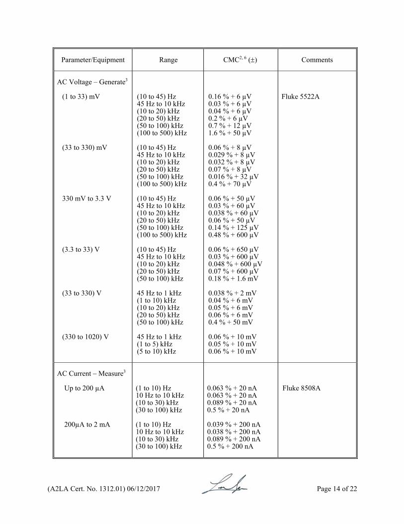
AC Voltage – Generate3
(1 to 33) mV (33 to 330) mV 330 mV to 3.3 V (3.3 to 33) V (33 to 330) V (330 to 1020) V
(10 to 45) Hz 45 Hz to 10 kHz (10 to 20) kHz (20 to 50) kHz (50 to 100) kHz (100 to 500) kHz (10 to 45) Hz 45 Hz to 10 kHz (10 to 20) kHz (20 to 50) kHz (50 to 100) kHz (100 to 500) kHz (10 to 45) Hz 45 Hz to 10 kHz (10 to 20) kHz (20 to 50) kHz (50 to 100) kHz (100 to 500) kHz (10 to 45) Hz 45 Hz to 10 kHz (10 to 20) kHz (20 to 50) kHz (50 to 100) kHz 45 Hz to 1 kHz (1 to 10) kHz (10 to 20) kHz (20 to 50) kHz (50 to 100) kHz 45 Hz to 1 kHz (1 to 5) kHz (5 to 10) kHz
0.16 % + 6 µV 0.03 % + 6 µV 0.04 % + 6 µV 0.2 % + 6 µV 0.7 % + 12 µV 1.6 % + 50 µV 0.06 % + 8 µV 0.029 % + 8 µV 0.032 % + 8 µV 0.07 % + 8 µV 0.016 % + 32 µV 0.4 % + 70 µV 0.06 % + 50 µV 0.03 % + 60 µV 0.038 % + 60 µV 0.06 % + 50 µV 0.14 % + 125 µV 0.48 % + 600 µV 0.06 % + 650 µV 0.03 % + 600 µV 0.048 % + 600 µV 0.07 % + 600 µV 0.18 % + 1.6 mV 0.038 % + 2 mV 0.04 % + 6 mV 0.05 % + 6 mV 0.06 % + 6 mV 0.4 % + 50 mV 0.06 % + 10 mV 0.05 % + 10 mV 0.06 % + 10 mV
Fluke 5522A
AC Current – Measure3 Up to 200 µA 200µA to 2 mA
(1 to 10) Hz 10 Hz to 10 kHz (10 to 30) kHz (30 to 100) kHz (1 to 10) Hz 10 Hz to 10 kHz (10 to 30) kHz (30 to 100) kHz
0.063 % + 20 nA 0.063 % + 20 nA 0.089 % + 20 nA 0.5 % + 20 nA 0.039 % + 200 nA 0.038 % + 200 nA 0.089 % + 200 nA 0.5 % + 200 nA
Fluke 8508A
(A2LA Cert. No. 1312.01) 06/12/2017 Page 15 of 22
Parameter/Equipment
Range CMC2, 6 ()
Comments
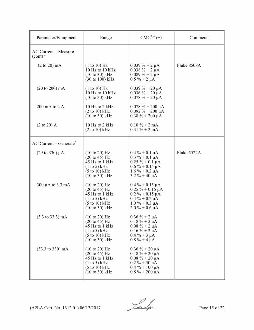
AC Current – Measure (cont) 3 (2 to 20) mA (20 to 200) mA 200 mA to 2 A (2 to 20) A
(1 to 10) Hz 10 Hz to 10 kHz (10 to 30) kHz (30 to 100) kHz (1 to 10) Hz 10 Hz to 10 kHz (10 to 30) kHz 10 Hz to 2 kHz (2 to 10) kHz (10 to 30) kHz 10 Hz to 2 kHz (2 to 10) kHz
0.039 % + 2 µA 0.038 % + 2 µA 0.089 % + 2 µA 0.5 % + 2 µA 0.039 % + 20 µA 0.036 % + 20 µA 0.078 % + 20 µA 0.078 % + 200 µA 0.092 % + 200 µA 0.38 % + 200 µA 0.10 % + 2 mA 0.31 % + 2 mA
Fluke 8508A
AC Current – Generate3 (29 to 330) µA 300 µA to 3.3 mA (3.3 to 33.3) mA (33.3 to 330) mA
(10 to 20) Hz (20 to 45) Hz 45 Hz to 1 kHz (1 to 5) kHz (5 to 10) kHz (10 to 30) kHz (10 to 20) Hz (20 to 45) Hz 45 Hz to 1 kHz (1 to 5) kHz (5 to 10) kHz (10 to 30) kHz (10 to 20) Hz (20 to 45) Hz 45 Hz to 1 kHz (1 to 5) kHz (5 to 10) kHz (10 to 30) kHz (10 to 20) Hz (20 to 45) Hz 45 Hz to 1 kHz (1 to 5) kHz (5 to 10) kHz (10 to 30) kHz
0.4 % + 0.1 μA 0.3 % + 0.1 μA 0.25 % + 0.1 μA 0.6 % + 0.15 μA 1.6 % + 0.2 μA 3.2 % + 40 μA 0.4 % + 0.15 μA 0.25 % + 0.15 μA 0.2 % + 0.15 μA 0.4 % + 0.2 μA 1.0 % + 0.3 μA 2.0 % + 0.6 μA 0.36 % + 2 μA 0.18 % + 2 μA 0.08 % + 2 μA 0.16 % + 2 μA 0.4 % + 3 μA 0.8 % + 4 μA 0.36 % + 20 μA 0.18 % + 20 μA 0.08 % + 20 μA 0.2 % + 50 μA 0.4 % + 100 μA 0.8 % + 200 μA
Fluke 5522A
(A2LA Cert. No. 1312.01) 06/12/2017 Page 16 of 22
Parameter/Equipment
Range CMC2, 6 ()
Comments
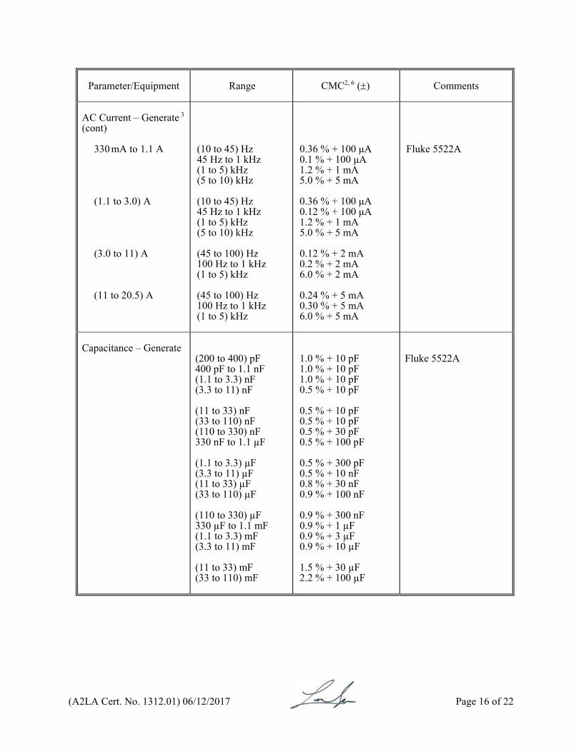
AC Current – Generate 3 (cont)
330 mA to 1.1 A (1.1 to 3.0) A (3.0 to 11) A (11 to 20.5) A
(10 to 45) Hz 45 Hz to 1 kHz (1 to 5) kHz (5 to 10) kHz (10 to 45) Hz 45 Hz to 1 kHz (1 to 5) kHz (5 to 10) kHz (45 to 100) Hz 100 Hz to 1 kHz (1 to 5) kHz (45 to 100) Hz 100 Hz to 1 kHz (1 to 5) kHz
0.36 % + 100 μA 0.1 % + 100 μA 1.2 % + 1 mA 5.0 % + 5 mA 0.36 % + 100 μA 0.12 % + 100 μA 1.2 % + 1 mA 5.0 % + 5 mA 0.12 % + 2 mA 0.2 % + 2 mA 6.0 % + 2 mA 0.24 % + 5 mA 0.30 % + 5 mA 6.0 % + 5 mA
Fluke 5522A
Capacitance – Generate
(200 to 400) pF 400 pF to 1.1 nF
(1.1 to 3.3) nF (3.3 to 11) nF (11 to 33) nF (33 to 110) nF (110 to 330) nF 330 nF to 1.1 µF
(1.1 to 3.3) µF (3.3 to 11) µF (11 to 33) µF (33 to 110) µF (110 to 330) µF 330 µF to 1.1 mF
(1.1 to 3.3) mF (3.3 to 11) mF (11 to 33) mF (33 to 110) mF
1.0 % + 10 pF 1.0 % + 10 pF 1.0 % + 10 pF 0.5 % + 10 pF 0.5 % + 10 pF 0.5 % + 10 pF 0.5 % + 30 pF 0.5 % + 100 pF 0.5 % + 300 pF 0.5 % + 10 nF 0.8 % + 30 nF 0.9 % + 100 nF 0.9 % + 300 nF 0.9 % + 1 µF 0.9 % + 3 µF 0.9 % + 10 µF 1.5 % + 30 µF 2.2 % + 100 µF
Fluke 5522A

(A2LA Cert. No. 1312.01) 06/12/2017 Page 17 of 22
Parameter/Equipment
Range CMC2 ()
Comments
Electrical Calibration of Thermocouples – Generate3 Type B Type C Type E Type J Type K Type L Type N Type R Type S
600 °C to 800 °C 800 °C to 1000 °C 1000 °C to 1550 °C 1550 °C to 1820 °C 0° to 150 °C 150 °C to 650 °C 650 °C to 1000 °C 1000 °C to 1800 °C 1800 °C to 2316 °C -250 °C to -100 °C -100 °C to -25 °C -25 °C to 350 °C 350 °C to 650 °C 650 °C to 1000 °C -210 °C to -100 °C -100 °C to -30 °C -30 °C to 150 °C 150 °C to 760 °C 760 °C to 1200 °C -200 °C to -100 °C -100 °C to -25 °C -25°C to 120 °C 120 °C to 1000 °C 1000 °C to 1372 °C -200 °C to -100 °C -100 °C to 800 °C 800 °C to 900 °C -200 °C to -100 °C -100 °C to -25 °C -25 °C to 120 °C 120 °C to 410 °C 410 °C to 1300 °C 0 °C to 250 °C 250 °C to 400 °C 400 °C to 1000 °C 1000 °C to 1767 °C 0 °C to 250 °C 250 °C to 1000 °C 1000 °C to 1400 °C 1400 °C to 1767 °C
0.55 °C 0.43 °C 0.38 °C 0.42 °C 0.38 °C 0.33 °C 0.39 °C 0.63 °C 1.1 °C 0.63 °C 0.20 °C 0.18 °C 0.20 °C 0.27 °C 0.34 °C 0.20 °C 0.18 °C 0.22 °C 0.29 °C 0.42 °C 0.23 °C 0.20 °C 0.33 °C 0.50 °C 0.47 °C 0.33 °C 0.22 °C 0.50 °C 0.28 °C 0.24 °C 0.23 °C 0.34 °C 0.72 °C 0.44 °C 0.42 °C 0.50 °C 0.59 °C 0.45 °C 0.47 °C 0.58 °C
Fluke 5522A

(A2LA Cert. No. 1312.01) 06/12/2017 Page 18 of 22
Parameter/Equipment
Range CMC2 ()
Comments
Electrical Calibration of Thermocouples - Generate 3 (cont)
Type T Type U
-250 °C to -150 °C -150 °C to 0 °C 0 °C to 120 °C 120 °C to 400 °C -200 °C to 0 °C 0 °C to 600 °C
0.79 °C 0.30 °C 0.20 °C 0.13 °C 0.70 °C 0.34 °C
Fluke 5522A
Electrical Calibration of RTDs – Generate 3
Pt 385 (100 Ω) Pt 3926 (100 Ω) Pt 3916 (100 Ω) Pt 385 (200 Ω)
-200 °C to -80 °C -80 °C to 0 °C 0 °C to 100 °C 100 °C to 300 °C 300 °C to 400 °C 400 °C to 630 °C 630 °C to 800 °C -200 °C to -80 °C -80 °C to 0 °C 0 °C to 100 °C 100 °C to 300 °C 300 °C to 400 °C 400 °C to 630 °C -200 °C to -190 °C -190 °C to -80 °C -80 °C to 0 °C 0 °C to 100 °C 100 °C to 260 °C 260 °C to 300 °C 300 °C to 400 °C 400 °C to 600 °C 600 °C to 630 °C -200 °C to -80 °C -80 °C to 0 °C 0 °C to 100 °C 100 °C to 260 °C 260 °C to 300 °C 300 °C to 400 °C 400 °C to 600 °C 600 °C to 630 °C
0.063 °C 0.063 °C 0.088 °C 0.11 °C 0.13 °C 0.15 °C 0.29 °C 0.063 °C 0.063 °C 0.088 °C 0.11 °C 0.13 °C 0.15 °C 0.31 °C 0.05 °C 0.063 °C 0.075 °C 0.088 °C 0.10 °C 0.11 °C 0.13 °C 0.29 °C 0.05 °C 0.05 °C 0.05 °C 0.063 °C 0.15 °C 0.16 °C 0.18 °C 0.20 °C
Fluke 5522A
(A2LA Cert. No. 1312.01) 06/12/2017 Page 19 of 22
Parameter/Equipment
Range CMC2 ()
Comments
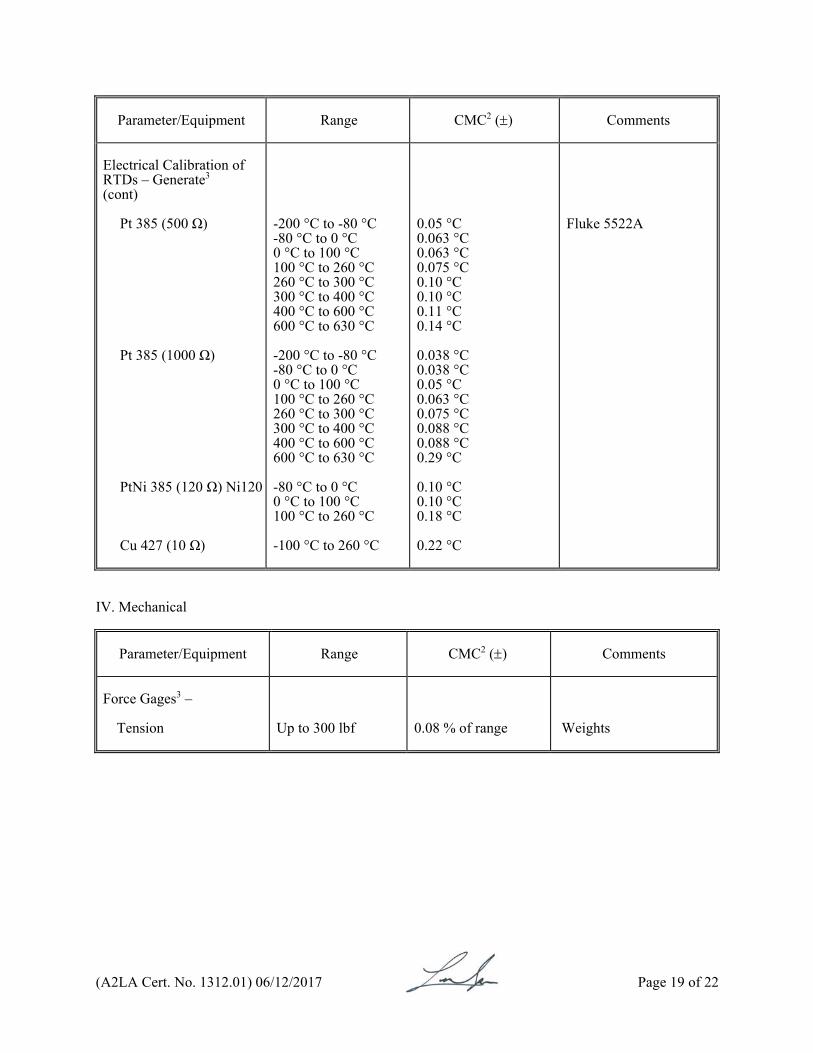
Electrical Calibration of RTDs – Generate3 (cont)
Pt 385 (500 Ω) Pt 385 (1000 Ω) PtNi 385 (120 Ω) Ni120 Cu 427 (10 Ω)
-200 °C to -80 °C -80 °C to 0 °C 0 °C to 100 °C 100 °C to 260 °C 260 °C to 300 °C 300 °C to 400 °C 400 °C to 600 °C 600 °C to 630 °C -200 °C to -80 °C -80 °C to 0 °C 0 °C to 100 °C 100 °C to 260 °C 260 °C to 300 °C 300 °C to 400 °C 400 °C to 600 °C 600 °C to 630 °C -80 °C to 0 °C 0 °C to 100 °C 100 °C to 260 °C -100 °C to 260 °C
0.05 °C 0.063 °C 0.063 °C 0.075 °C 0.10 °C 0.10 °C 0.11 °C 0.14 °C 0.038 °C 0.038 °C 0.05 °C 0.063 °C 0.075 °C 0.088 °C 0.088 °C 0.29 °C 0.10 °C 0.10 °C 0.18 °C 0.22 °C
Fluke 5522A
IV. Mechanical
Parameter/Equipment
Range CMC2 ()
Comments
Force Gages3 –
Tension
Up to 300 lbf
0.08 % of range
Weights
(A2LA Cert. No. 1312.01) 06/12/2017 Page 20 of 22
Parameter/Equipment
Range CMC2 ()
Comments
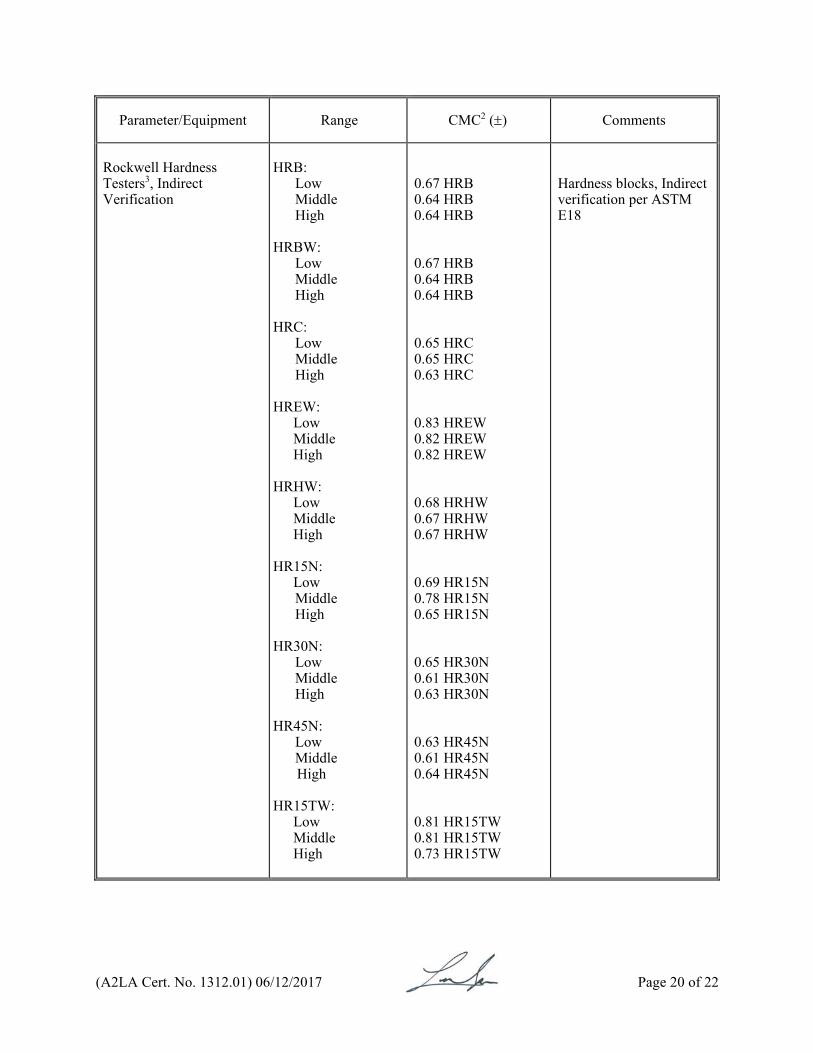
Rockwell Hardness Testers3, Indirect Verification
HRB: Low Middle High HRBW: Low Middle High HRC: Low Middle High HREW:
Low Middle High
HRHW:
Low Middle High
HR15N:
Low Middle High HR30N: Low Middle High HR45N: Low Middle
High HR15TW:
Low Middle High
0.67 HRB 0.64 HRB 0.64 HRB 0.67 HRB 0.64 HRB 0.64 HRB 0.65 HRC 0.65 HRC 0.63 HRC 0.83 HREW 0.82 HREW 0.82 HREW 0.68 HRHW 0.67 HRHW 0.67 HRHW 0.69 HR15N 0.78 HR15N 0.65 HR15N 0.65 HR30N 0.61 HR30N 0.63 HR30N 0.63 HR45N 0.61 HR45N 0.64 HR45N 0.81 HR15TW 0.81 HR15TW 0.73 HR15TW
Hardness blocks, Indirect verification per ASTM E18
(A2LA Cert. No. 1312.01) 06/12/2017 Page 21 of 22
Parameter/Equipment
Range CMC2 ()
Comments
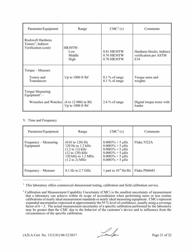
Rockwell Hardness Testers3, Indirect Verification (cont)
HR30TW:
Low Middle High
0.81 HR30TW 0.76 HR30TW 0.70 HR30TW
Hardness blocks, Indirect verification per ASTM E18
Torque – Measure
Testers and Transducers
Up to 1000 ft·lbf
0.1 % of range 0.1 % of range
Torque arms and weights
Torque Measuring Equipment3 –
Wrenches and Watches
(4 to 12 000) in·lbf, Up to 1000 ft·lbf
2.6 % of range
Digital torque tester with loader
V. Time and Frequency
Parameter/Equipment
Range CMC2 ()
Comments
Frequency – Measuring Equipment
(0.01 to 120) Hz 120 Hz to 1.2 kHz (1.2 to 12) kHz (12 to 120) kHz 120 kHz to 1.2 MHz (1.2 to 2) MHz
0.0003% + 5 µHz 0.0003% + 5 µHz 0.0003% + 5 µHz 0.0003% + 5 µHz 0.0003% + 5 µHz 0.0003% + 5 µHz
Fluke 5522A
Frequency – Measure
0.1 Hz to 2.7 GHz 1 part in 10-8 Hz/Hz Fluke PM6681
______________________ 1 This laboratory offers commercial dimensional testing, calibration and field calibration service. 2 Calibration and Measurement Capability Uncertainty (CMC) is the smallest uncertainty of measurement
that a laboratory can achieve within its scope of accreditation when performing more or less routine calibrations of nearly ideal measurement standards or nearly ideal measuring equipment. CMCs represent expanded uncertainties expressed at approximately the 95 % level of confidence, usually using a coverage factor of k = 2. The actual measurement uncertainty of a specific calibration performed by the laboratory may be greater than the CMC due to the behavior of the customer’s device and to influences from the circumstances of the specific calibration.

(A2LA Cert. No. 1312.01) 06/12/2017 Page 22 of 22
3 Field calibration service is available for this calibration and this laboratory meets A2LA R104 – General Requirements: Accreditation of Field Testing and Field Calibration Laboratories for these calibrations. Please note the actual measurement uncertainties achievable on a customer's site can normally be expected to be larger than the CMC found on the A2LA Scope. Allowance must be made for aspects such as the environment at the place of calibration and for other possible adverse effects such as those caused by transportation of the calibration equipment. The usual allowance for the actual uncertainty introduced by the item being calibrated, (e.g. resolution) must also be considered and this, on its own, could result in the actual measurement uncertainty achievable on a customer’s site being larger than the CMC.
4 In the statement of Calibration and Measurement Capabilities, L is the numerical value of the nominal
length of the device measured in inches. 5 This laboratory meets R205 – Specific Requirements: Calibration Laboratory Accreditation Program
for the types of dimensional tests listed above and is considered equivalent to that of a calibration. 6 The measurands stated are generated with the Fluke 5522 or 8500 series of instruments. This capability
is suitable for the calibration of the devices intended to measure the stated measurand in the ranges indicated. CMCs are expressed as either a specific value that covers the full range or as a percentage of the reading plus a fixed floor specification.

For the calibrations to which this accreditation applies, please refer to the laboratory’s Calibration Scope of Accreditation.
Accredited Laboratory
A2LA has accredited
MICRO LABORATORIES, INC. Mentor, OH
for technical competence in the field of
Calibration
This laboratory is accredited in accordance with the recognized International Standard ISO/IEC 17025:2005 General requirements for the competence of testing and calibration laboratories. This laboratory also meets the requirements of ANSI/NCSLI
Z540-1-1994 and R205 – Specific Requirements: Calibration Laboratory Accreditation Program. This accreditation demonstrates technical competence for a defined scope and the operation of a laboratory quality management system
(refer to joint ISO-ILAC-IAF Communiqué dated 8 January 2009).
Presented this 12th day of June 2017. _______________________ President and CEO For the Accreditation Council Certificate Number 1312.01 Valid to July 31, 2019
Top Related