


Languages
Pages
Legal


tools
Mold Finish comparison kitMFK 1200
Expanded version - 12 samples finished to SPI standards
- Eliminates errors or guesswork in achieving desired or specified finishes- Saves time by eliminating over-polishing- Provides a visual and numerical standard for specifying mold/part finishes
Professionally finished to SPI standards, this kit is an invaluable tool for both selection of finishes required and comparison to work in progress. The visual and numerical standards are also helpful in communications between end user, molder and moldmaker.Each finish has been generated on a 25 mm diameter x 9 mm thick piece oh H13 steel. Edges are chamfered and the outside diameter is knurled for safe, easy pick-up and handling.Finish numbers are stamped on the back of each sample for quick reference. A molded plaque in the kit’s lid shows the part finish that result from each mold finish.
Finish Type Description Roughness average Micro-inches
Roughness average Micron
Comments
A1 Grade 3 diamond buff 0-1 0-0,025 • Formirrororopticalfinishes• Most time consuming• Steel grade important to
results• (Steel DME 6 and 7 recom-
mended)
A2 Grade 6 diamond buff 1-2 0,025-0,05
A3 Grade 15 diamond buff 2-3 0,05-0,076
B1 600 grit paper 2-3 0,05-0,076• Removes all tool and
machining marks• Provides good mould release• Lightreflectingfinishon
moulded part, some sheen
B2 400 grit paper 4-5 0,10-0,127
B3 320 grit paper 9-10 0,23-0,25
C1 600 stone 10-12 0,25-0,30• Removes all tool and
machining marks• Provides good mold release• Mutefinishonmoldedpart,
no sheen
C2 400 stone 25-28 0,64-0,71
C3 320 stone 38-42 0,97-1,07
D1 Dry blast glass bead 11200 distance at 0,7Mpa; 5 secs 10-12 0,25-0,30 • Fordecorativefinishes
• Often used for diecast andthermoset tooling
• Helps hide shrink marks andother imperfections
• Dull,non-reflectingfinishonmolded or cast part
D2 Dry blast 240 oxyde125 mm distance at 0,7 Mpa; 5 secs 26-32 0,66-0,81
D3 Dry blast 24 oxyde150 mm distance at 0,7 Mpa; 5 secs 190-230 4,83-5,84
REFMFK 1200
www.diemouldequipment.com.au Tel 1800 224 135
tools
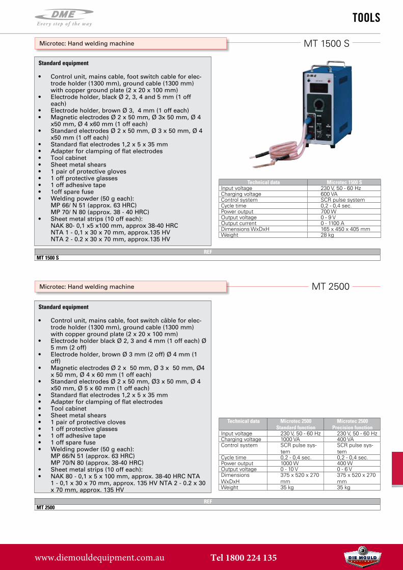
Microtec: Hand welding machine
Microtec: Hand welding machine
MT 1500 S
MT 2500
Standard equipment
• Control unit, mains cable, foot switch cable for elec-trode holder (1300 mm), ground cable (1300 mm)with copper ground plate (2 x 20 x 100 mm)
• Electrode holder, black Ø 2, 3, 4 and 5 mm (1 offeach)
• Electrode holder, brown Ø 3, 4 mm (1 off each)• Magnetic electrodes Ø 2 x 50 mm, Ø 3x 50 mm, Ø 4
x50 mm, Ø 4 x60 mm (1 off each)• Standard electrodes Ø 2 x 50 mm, Ø 3 x 50 mm, Ø 4
x50 mm (1 off each)• Standard flat electrodes 1,2 x 5 x 35 mm• Adapter for clamping of flat electrodes• Tool cabinet• Sheet metal shears• 1 pair of protective gloves• 1 off protective glasses• 1 off adhesive tape• 1off spare fuse• Welding powder (50 g each):
MP 66/ N 51 (approx. 63 HRC)MP 70/ N 80 (approx. 38 - 40 HRC)
• Sheet metal strips (10 off each):NAK 80- 0,1 x5 x100 mm, approx 38-40 HRCNTA 1 - 0,1 x 30 x 70 mm, approx.135 HVNTA 2 - 0.2 x 30 x 70 mm, approx.135 HV
Standard equipment
• Control unit, mains cable, foot switch câble for elec-trode holder (1300 mm), ground cable (1300 mm)with copper ground plate (2 x 20 x 100 mm)
• Electrode holder black Ø 2, 3 and 4 mm (1 off each) Ø5 mm (2 off)
• Electrode holder, brown Ø 3 mm (2 off) Ø 4 mm (1off)
• Magnetic electrodes Ø 2 x 50 mm, Ø 3 x 50 mm, Ø4x 50 mm, Ø 4 x 60 mm (1 off each)
• Standard electrodes Ø 2 x 50 mm, Ø3 x 50 mm, Ø 4x50 mm, Ø 5 x 60 mm (1 off each)
• Standard flat electrodes 1,2 x 5 x 35 mm• Adapter for clamping of flat electrodes• Tool cabinet• Sheet metal shears• 1 pair of protective cloves• 1 off protective glasses• 1 off adhesive tape• 1 off spare fuse• Welding powder (50 g each):
MP 66/N 51 (approx. 63 HRC)MP 70/N 80 (approx. 38-40 HRC)
• Sheet metal strips (10 off each):• NAK 80 - 0,1 x 5 x 100 mm, approx. 38-40 HRC NTA
1 - 0,1 x 30 x 70 mm, approx. 135 HV NTA 2 - 0.2 x 30x 70 mm, approx. 135 HV
Technical data Microtec 1500 SInput voltage 230 V, 50 - 60 HzCharging voltage 600 VAControl system SCR pulse systemCycle time 0,2 - 0,4 sec.Power output 700 WOutput voltage 0 - 9 VOutput current 0 - 1100 ADimensions WxDxH 165 x 450 x 405 mmWeight 28 kg
Technical data Microtec 2500Standard function
Microtec 2500Precision function
Input voltage 230 V, 50 - 60 Hz 230 V, 50 - 60 HzCharging voltage 1000 VA 400 VAControl system SCR pulse sys-
temSCR pulse sys-tem
Cycle time 0,2 - 0,4 sec. 0,2 - 0,4 sec.Power output 1000 W 400 WOutput voltage 0 - 10 V 0 - 6 VDimensions WxDxH
375 x 520 x 270 mm
375 x 520 x 270 mm
Weight 35 kg 35 kg
REFMT 1500 S
REFMT 2500
www.diemouldequipment.com.au Tel 1800 224 135
tools
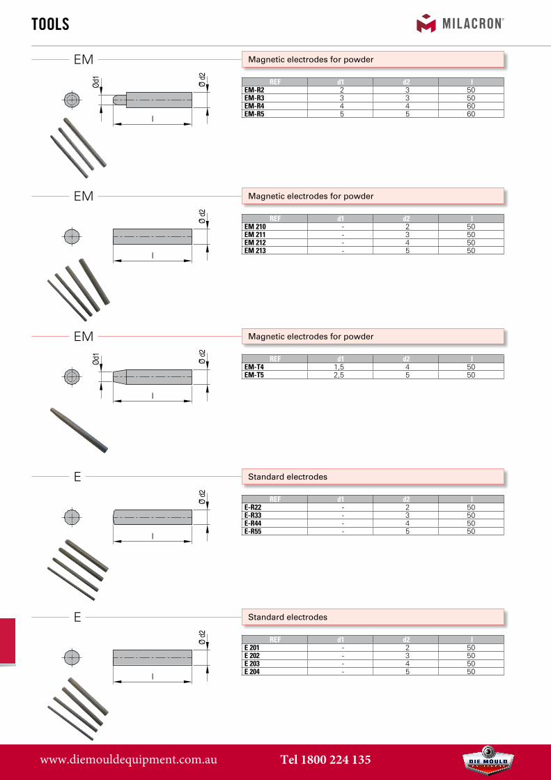
REF d1 d2 lEM-R2 2 3 50EM-R3 3 3 50EM-R4 4 4 60EM-R5 5 5 60
REF d1 d2 lEM 210 - 2 50EM 211 - 3 50EM 212 - 4 50EM 213 - 5 50
REF d1 d2 lEM-T4 1,5 4 50EM-T5 2,5 5 50
REF d1 d2 lE-R22 - 2 50E-R33 - 3 50E-R44 - 4 50E-R55 - 5 50
REF d1 d2 lE 201 - 2 50E 202 - 3 50E 203 - 4 50E 204 - 5 50
Magnetic electrodes for powder
Magnetic electrodes for powder
Magnetic electrodes for powder
Standard electrodes
Standard electrodes
EM
EM
EM
E
E
www.diemouldequipment.com.au Tel 1800 224 135

tools
REF d1 d2 lE 205 1,2 5 35E 206 2,2 5 35
REF d1 d2 lE-SP 2 - 2 45
REF d1 d2 lE-SR2 - 2 45
REF suitable for electrodes REF suitable for electrodesH-301 EM-210, E-R22, E-201,
E-SP2, E-SR2ø 15 mm
A-403 E-205
H-302 EM-R2, EM-R3, EM211, E-R33, E-202
ø 15 mm
A-404 E-206
H-303 EM-R4, EM212, EM-T4, E-R44, E-203
ø 15 mm
H-304 EM-R5, EM213, EM-T5, E-R55, E-204
ø 15 mm
H-306 EM-210, E-R22, E-201, E-SP2, E-SR2
ø 12 mm
H-307 EM-R2, EM-R3, EM211, E-R33, E-202
ø 12 mm
Standard electrodes
Standard electrodes
Standard electrodes
Electrode holder / Adapter
E
E
E
H / A
www.diemouldequipment.com.au Tel 1800 224 135

tools
REF h a iSL 1450 0,5 8 75
1,01,52,0 10 802,53,03,54,0 12 855,06,07,0 14 908,09,0 15 100
10,0
REF h a iSL 1460 0,5 8 75
1,01,52,0 10 802,53,03,54,0 12 855,06,07,0 14 908,09,0 15 100
10,0
REF h a iSL 1455 0,5 8 75
1,01,52,0 10 802,53,03,54,0 12 855,06,07,0 14 908,09,0 15 100
10,0
REF h a iSL 1465 0,5 8 75
1,01,52,0 10 802,53,03,54,0 12 855,06,07,0 14 908,09,0 15 100
10,0
Hand stamp set Mat.: C 105 W1 - 60 ±2 HRC
Hand stamp set Mat.: C 105 W1 - 60 ±2 HRC
Hand stamp set Mat.: C 105 W1 - 60 ±2 HRC
Hand stamp set Mat.: C 105 W1 - 60 ±2 HRC
SL 1450
SL 1460
SL 1455
SL 1465
Plastic box with a set ot 9 digits (legible after mark-ing)
Plastic box with a set ot 9 di gits (mirror inverted after marking)
Plastic box with a set of 26 alphabetic characters (leg-ible after marking)
Plastic box with a set of 26 alphabetic characters (mirror inverted after mark-ing)
www.diemouldequipment.com.au Tel 1800 224 135

tools
REFPZ 7-3
REFPZ 7
REFPZ 8APZ 8B
Pneumatic pliers for cutting off sprues
Pneumatic pliers for cutting off sprues
Pneumatic pliers for cutting off sprues
PZ 7-3
PZ 7
PZ 8A - PZ 8B
Suitable for pliers Inserts allowing cuts up to 3,5 mm pliers opening. Appropriate inserts for pliers are Ze 3, ZeV, Ze 4.
Compr.-air consumption/cut ~78 cm3Pliers opening 3,5 mmHose 1,5 mConnection Nipple R 1/4”Pmax 6 bar
The pneumatic pillers PZ 7, PZ 8A and PZ 8B can be sup-plied with special inserts for handling devices
Suitable for pliers Inserts allowing cuts up to 10 mm pliers opening. Appropriate inserts for pliers are Ze 3, ZeV, Ze 4. With safety-device!
Compr.-air consumption/cut ~300 cm3Pliers opening 10 mmHose 1,5 mConnection Nipple R 1/4”Pmax 6 bar
The pneumatic pillers PZ 7, PZ 8A and PZ 8B can be sup-plied with special inserts for handling devices
Suitable for pliers Inserts allowing cuts up to A: 10 mm / B: 14 mm pliers opening. Appropriate inserts for pliers are Ze 3a, ZeVa, Ze 4a. With safety-device!
Compr.-air consumption/cut ~425 cm3Hose 1,5 mConnection Nipple R 1/4”Pmax 6 bar
The pneumatic pillers PZ 7, PZ 8A and PZ 8B can be sup-plied with special inserts for handling devices
www.diemouldequipment.com.au Tel 1800 224 135

tools
REF forPZ 7-3 PZ 7-3 / PZ 7ZE 3A PZ 8A / PZ 8B
REF forZE 3V PZ 7-3 / PZ 7ZE 3VA PZ 8A / PZ 8B
REF forZE 4 PZ 7-3 / PZ 7ZE 4A PZ 8A / PZ 8B
Plier inserts for pneumatic pliers
Plier inserts for pneumatic pliers
Plier inserts for pneumatic pliers
ZE 3 - ZE 3A
ZE 3V - ZE 3VA
ZE 4 - ZE 4A
Cutting perfor mance of plier inserts when used in pneuma-tic pliers
Plier insert induction har dened to 58 HRC. Cutting perfor-mance of plier inserts when used in pneumatic pliers
REF Plastic Ø Cu Ø Al ØPZ 7-3 3,0 3,0 3,0PZ 7 8,0 4,0 4,0PZ 8A 8,0 5,0 4,0PZ 8B 12,0 4,0 4,0
REF Plastic Ø Cu Ø Al ØPZ 7-3 3,0 3,0 3,0PZ 7 9,0 3,5 3,5PZ 8A 9,0 5,0 4,5PZ 8B 12,0 3,5 3,0
www.diemouldequipment.com.au Tel 1800 224 135

191 mm
Ø 5
6 m
m
124 mm
112 mm
Ø 3
6 m
mØ
20
mm
tools
REFMR30A
REFMR10
REFMR3
Pneumatic cutters - hand held or bracket mounted
Pneumatic cutters - hand held or bracket mounted
Pneumatic cutters - hand held or bracket mounted
MR30A
MR10
MR3
• 2740 N cutting power (blade sold seperately)• Air consumption: 584 cm³/stroke• Air pressure: 0,5~0,6 MPa• Weight: 520 gr• Blade F9P (Standard)
*Different sizes of blades available for these particular mod-els!
• 1/4” NPT fitting• Cutting capacity plastic: 6,5 - 13 mm• Blades see p. 10
• 580 N cutting power (blade sold seperately)• Air consumption: 116 cm³/stroke• Air pressure: 0,4~0,5 MPa• Weight: 200 gr• Blade F3 (Standard)• 1/4” NPT fitting• Cutting capacity plastic: 2,6 - 4 mm• Blades see p. 10
• 265 N cutting power (blade sold seperately)• Air consumption: 35 cm³/stroke• Air pressure: 0,4~0,5 MPa• Weight: 90 gr• Blade F10 (Standard)• 1/4” NPT fitting• Cutting capacity plastic: max 1 mm• Blades see p. 10
Blade not included
Blade not included
Blade not included
www.diemouldequipment.com.au Tel 1800 224 135

286 mm
Ø 5
6 m
mtools
Pneumatic cutters - hand held or bracket mounted
Blades
How to order
MP35A
Info
Info
• Heavy duty• 4410 N cutting power (blade sold seperately)• Air consumption: 956 cm³/stroke• Air pressure: 0,5~0,6 MPa• Weight: 830 gr• 1/4” NPT fitting• Blade F9P* (Standard)
*Different sizes of blades available for these particular mod-els!
• Cutting capacity plastic: 6,5 - 13 mm• Blades see p. 10
REFMP35A
REF Blade REF Cutter a b c fCutting Capacity Ø mm
Soft plastic Hard plastic
Plas
tic C
uttin
g a
c
b f°
F10 MR3 24 12 2,5 15 1,0 -
F3 MR10 27 12 4,5 25 4,0 2,6
F9P MR30A - MR35A 65 38 15 15 10,0 - 13,0 6,5- 6,5
Leve
l Cut
ting
for p
last
ic a
c
b f°
FD10 MR3 24 10 2,5 40 1,0 -
FD3 MR10 27 10 4,5 40 4,0 2,6
FD9P MR30A - MR35A 59 27 14 30 10,0 - 13,0 6,5- 6,5
Flat
sur
face
for p
last
ic
b
c
a
F10S MR3 24 12 2,5 - 1,0 -
F3S MR10 27 13 4,5 - 4,0 2,6
F9PS MR30A - MR35A 65 37 15 - 10,0 - 13,0 6,5- 6,5
n = Standard
Ordering example: MP35A + F9PREF cutter REF blade
Blade not included
www.diemouldequipment.com.au Tel 1800 224 135

C
BA
AB
C
tools
REFMB-AMB-B
REF Weight (g) A (mm) B (mm) C (mm)FB70S 970 110 122 145FV80 600 83 69 48
Mounting Brackets
Foot valves
MB...
FB70S - FV80
• Type A: Mounting Bracket for MR-3 to MR-10 (dia.range =< 46 mm)
• Type B: Mounting Bracket for MR30A to MP35A (dia.range =48 - 56 mm)
• All brackets: Base= 140 x 120 mm• Height: 118 mm
• For use with all pneumatic cutters with one air inlet NPT fittings.
Type A
Type B
FB70S FV80
Foot valve Safety cover
Mounting bracket
Air cutter
www.diemouldequipment.com.au Tel 1800 224 135

L
F
F
Ø
tools
Helicol-Combi® Tool Balancing SystemHEC...
Applications:Balancing and supplying portable pneumatic tools.• On pre-assembly and assembly workstations.• On spot-welding and riveting stations.• On packaging lines: staplers, hoop binders, nailing
heads.2 functions of balancing and supplying the compressed air in one single integrated vertically suspended appara-tus.Fitted with a robust safety chain which prevents the spring from being strained, and a safe platform for sus-pension of larger air driven tools.
Installation:• Determine the attachment point for your balancing
unit after having mounted the air driven tool on thefree end. You will then obtain the effective height.
• Attach the balancing unit to a bracket. Helicol-Combi® can be attached in a number of ways: bydirect thread, with quick-release connectors, flexiblehose, or chain type suspension.
Construction:• Hose in special light protected blue color Polyamid
12.• Model HEC 50 is fitted with the SL type safety chain.
For tools up to For tools from
4.5 lbs. 4.5 to 11 lbs.
Tube ø 1/4” 3/8”
L 10” (254 mm) 15” (381 mm)
max. extension 40” (1016 mm) 70” (1778 mm)
Thread F 1/4” 3/8”
Coil ø 3-1/8” 4”
REF HEC2002 HEC5002
Polyurethane RecoilPU04-...
• Extremely flexible - resists kinking• Impervious to abrasion & heat• Made with pigtails on coil -no need for whip hoses• Less operator fatigue - low tension• Superior elasticity & coil memory• Special full flow fittings
The barb fittings used with our poly ure thane hose are designed with this unique serrated grip ping surface to hold the hose in place, es pe cial ly un der pressure.
REF Hose Size
Male Swivel
HoseLength
PU04-10S 1/4” 1/4” 10’ (3,0 m)
PU04-15S 1/4” 1/4” 15’ (4,6 m)
PU04-20S 1/4” 1/4” 20’ (6,1 m)
PU04-25S 1/4” 1/4” 25’ (7,6 m)
www.diemouldequipment.com.au Tel 1800 224 135
tools
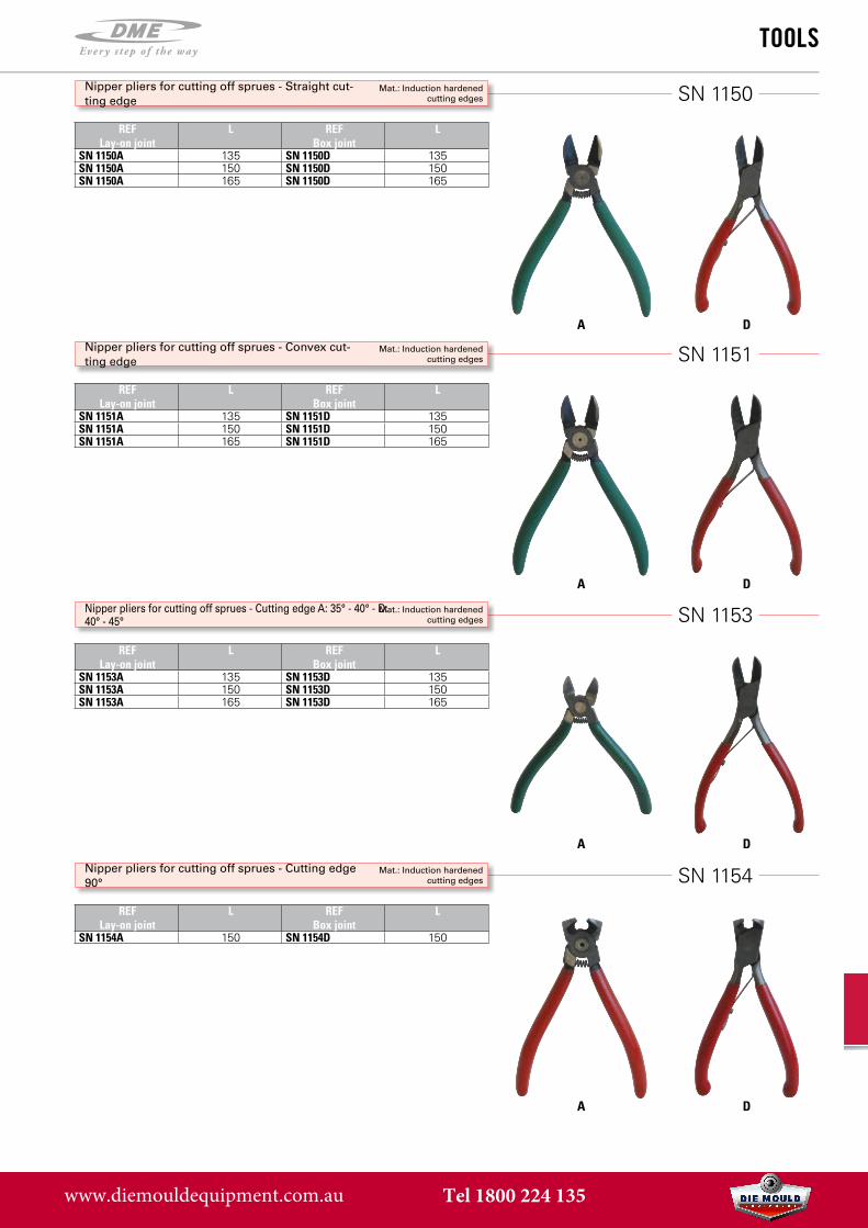
REFLay-on joint
L REF Box joint
L
SN 1150A 135 SN 1150D 135SN 1150A 150 SN 1150D 150SN 1150A 165 SN 1150D 165
REFLay-on joint
L REF Box joint
L
SN 1151A 135 SN 1151D 135SN 1151A 150 SN 1151D 150SN 1151A 165 SN 1151D 165
REFLay-on joint
L REF Box joint
L
SN 1153A 135 SN 1153D 135SN 1153A 150 SN 1153D 150SN 1153A 165 SN 1153D 165
REFLay-on joint
L REF Box joint
L
SN 1154A 150 SN 1154D 150
Nipper pliers for cutting off sprues - Straight cut-ting edge
Mat.: Induction hardened cutting edges
Nipper pliers for cutting off sprues - Convex cut-ting edge
Mat.: Induction hardened cutting edges
Nipper pliers for cutting off sprues - Cutting edge A: 35° - 40° - D: 40° - 45°
Mat.: Induction hardened cutting edges
Nipper pliers for cutting off sprues - Cutting edge 90°
Mat.: Induction hardened cutting edges
SN 1150
SN 1151
SN 1153
SN 1154
A
A
A
A
D
D
D
D
www.diemouldequipment.com.au Tel 1800 224 135

tools
REF LEM 1150 155
REFSpare blade set
Pcs.
EM 1150E 100
REFWF 620
REFWF 1540
Trimming knives for plastic parts / Spare blades set
Deburring tool
Deburring tool
EM 1150 / EM 1150E
WF 620
WF 1540
Safe deburring of hard plastics, non ferrous metals and mold steels.Ceramic blade
Safe deburring of hard plastics, non ferrous metals and mold steels.Ceramic blade
www.diemouldequipment.com.au Tel 1800 224 135

tools
Wax guns
Wax package
Stand for wax gun
REFFA 89-1FA 89-2
REF WeightFA 89-W 5 kg
REFFA 89-S
FA 89
FA 89-W
FA 89-S
Specification FA 89-1 FA 89-23,0 3,0 3,0Volt 220 V 220 V8,0 5,0 4,0Power 240 W 240 WVolume Wax 600 cm2 1800 cm2Operating pressure for air connection
6 - 8 bar 6 - 8 bar
Ø Sprue Nozzle 3 mm 3 mmEmpty weight 3,5 kg 8 kg
www.diemouldequipment.com.au Tel 1800 224 135

tools
OPTIM Service table for molds
Optim Table
Aluminium Tool Plate
Base Platform / Total Height 850 mm
REF Item descriptionOPTIM2515 Optim Table max 1500 kg OPTIM2520 Optim Table max 2000 kg OPTIM2530 Optim Table max 3000 kg OPTIM2515-850 Optim 2515 + Base PlatformOPTIM2515-850AL Optim 2515 + Base Platform + AL ToolplateOPTIM2520-850 Optim 2520 + Base Platform OPTIM2520-850AL Optim 2520 + Base Platform + AL ToolplateOPTIM2530-850 Optim 2530 + Base PlatformOPTIM2530-850AL Optim 2530 + Base Platform + AL ToolplateOPTIM850 Only Base Platform OPTIM850AL Only Base Platform + AL Toolplate
This new generation of platform is specifically conceived for:
• Opening and closing of moulds
• Access to each part of the mould for maintenance
• 90° Rotation of each mould-part for direct accessto the tool
• 3 sizes: 1500 kg / 2000 kg / 3000 kg
• Optional base-platform to raise total height to850 mm
Dimensions:
Standard Table : L 1200mm x W 580 mm x H 275 mm Pivot-piece : L 350 mm x W 550 mm
www.diemouldequipment.com.au Tel 1800 224 135
Top Related